Gallagher Group C30040X Prox Reader T10 Mifare User Manual
Gallagher Group Ltd Prox Reader T10 Mifare Users Manual
Users Manual
Page 1
Part Number: 3E2453 | Edi on 8
November 2012
The Gallagher T10 Mifare Reader
The Gallagher T10 Mifare Reader is a smart card proximity reader. It can be installed
as either an entry reader or exit reader.
The reader can read: Mifare DESFire EV1, Mifare Plus and Mifare Classic cards.
The reader sends informa on to the Gallagher Controller and acts upon informa on
sent from the Gallagher Controller. The reader itself does not make any access
decisions.
The Gallagher T10 Mifare Reader uses the Cardax IV communica ons protocol to
communicate with the Gallagher Controller.
Note: A French transla on of this document can be downloaded from the Gallagher
Support Site: hƩ p://support.gallagher.co
Before you begin
Shipment Contents
Check the shipment contains the following items:
• 1 x Gallagher T10 Reader facia assembly
• 1 x Gallagher T10 Reader base
• 1 x M3 Torx Post (T10) Security screw
• 2 x 25 mm No.6 self tapping, pan head, Phillips drive fi xing screws
• 2 x 40 mm No.6 self tapping, pan head, Phillips drive fi xing screws
InstallaƟ on Note
Gallagher T10 Mifare Reader
ATTENTION: This equipment contains components that can be damaged
by electrosta c discharge. Ensure both you and the equipment are earthed
before beginning any servicing.

Page 2
Gallagher T10 Mifare Reader
Edi on 8 | Part Number: 3E2453
November 2012
Installa on Note
Power Supply
The Gallagher T10 Mifare Reader is designed to operate over a supply voltage range
of 9 - 16 Vdc measured at the reader terminals. The opera ng current draw is
dependent on the supply voltage at the reader. At 12 Vdc the current draw is 82 mA
(standby). During card read, beeper and LED ac vity, the current will momentarily
reach 115 mA (peak).
The power source should be linear or a good quality switched-mode power supply.
The performance of the reader may be aff ected by a low quality, noisy power supply.
Cabling
The Gallagher T10 Mifare Reader requires a minimum cable size of 4 core
24 AWG (0.2 mm2) stranded security cable. This cable allows the transmission of
data (2 wires) and power (2 wires). When using a single cable to carry both power
supply and data, both the power supply voltage drop and data requirements must
be considered. Although the reader is specifi ed to operate at 9 Vdc, for good
engineering design it is recommended that the voltage at the reader should be
approximately 12 Vdc.
Examples of approved cables for connec ng a single Gallagher T10 Mifare Reader
to a Controller and power supply, showing maximum cable lengths for each type of
cable and the associated circuits are:
Manufacturer
reference Cable format*
Combined
power and data
in a single cable
Data only in a
single cable
CAT5E 4 twisted pair
Each 2 x 0.2 mm2 (24 AWG)
100 m (330 ) 300 m (1000 )
SEC472 4 x 0.2 mm2
Not twisted pairs (24 AWG)
100 m (330 ) 250 m (800 )
SEC4142 4 x 0.4 mm2
Not twisted pairs (21 AWG)
150 m (500 ) 150 m (500 )
BELDEN 8723 2 twisted pair
Each 2 x 0.4 mm2 (22 AWG)
100 m (330 ) 150 m (500 )
BELDEN 9842 2 twisted pair
Each 2 x 0.2 mm2 (24 AWG)
100 m (330 ) 200 m (650 )
* The matching of wire sizes to equivalent wire gauges are only approximate.
Grounding shielded cable may reduce the obtainable cable length by 25% to 30%.
Page 3
Gallagher T10 Mifare Reader
Installa on Note
Part Number: 3E2453 | Edi on 8
November 2012
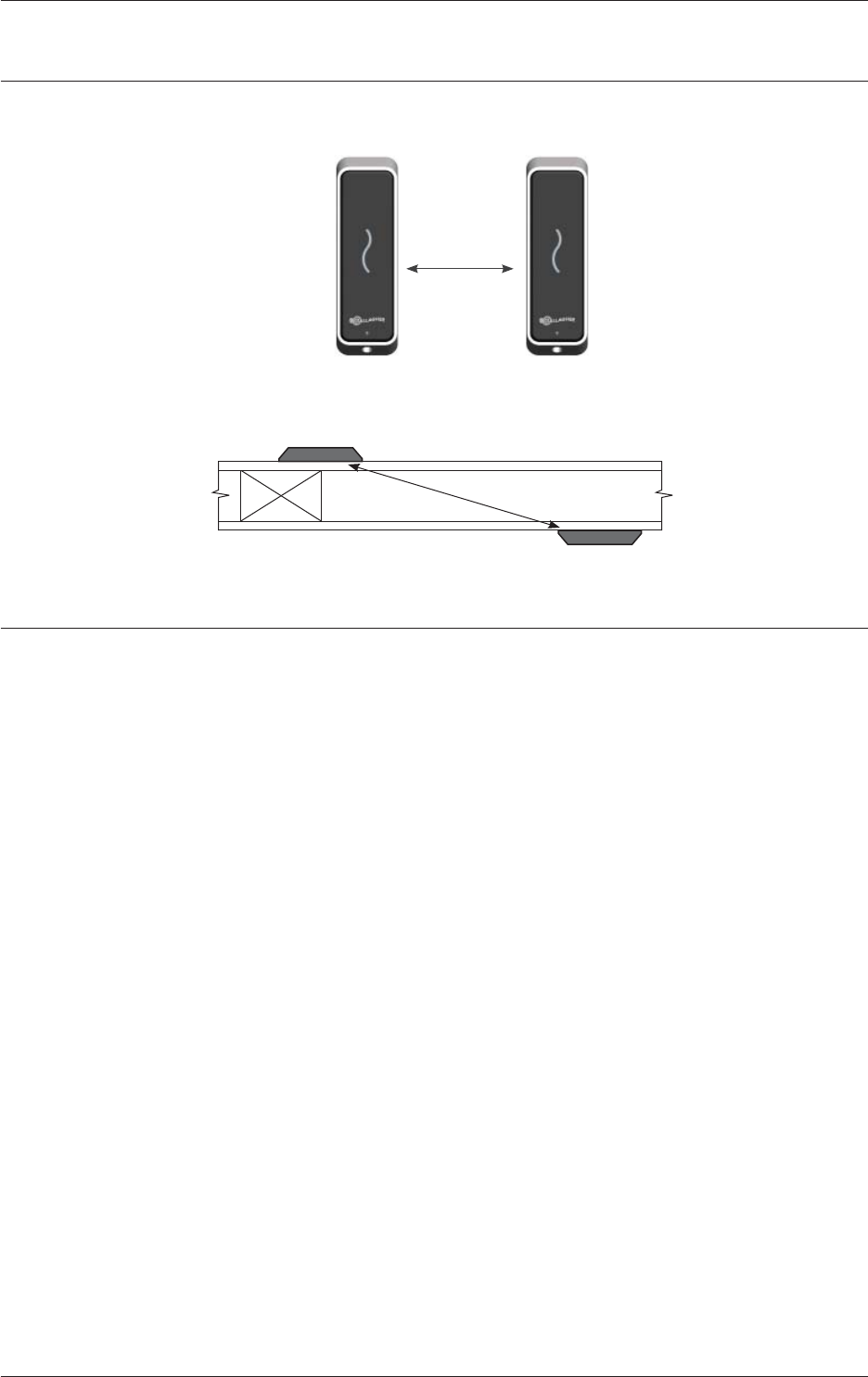
Distance between Proximity Readers
The distance separa ng any two proximity readers must not be less than 200 mm
(8 inches) in all direc ons.
200 mm
When moun ng a proximity reader on an internal wall, check that any reader fi xed
to the other side of the wall is not less than 200 mm (8 inches) away.
200 mm
InstallaƟ on
The Gallagher T10 Mifare Reader is designed to be mounted on any solid fl at
surface. However installa on on metal surfaces, par cularly those with a large
surface area will reduce read range. The extent to which the range is reduced will
depend upon the type of metal surface.
The recommended moun ng height for the reader is 1.1 m (3.6 ) from the fl oor
level to the centre of the reader device. However this may vary in some countries
and you should check local regula ons for varia ons to this height.
1. Using the drill template at the back of this installa on note as a guide, drill all
three holes. Drill the 13 mm (1/2 inch) diameter centre hole (this is the centre
hole for which the building cable will exit the moun ng surface) and the two
fi xing holes.
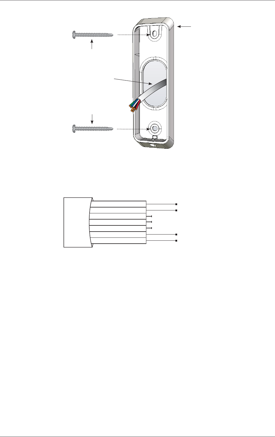
2. Run the building cabling out through the centre hole and through the reader
base.
3. Secure the base to the moun ng surface using the two fi xing screws provided.
It is important the base of the reader is fl ush with and ght against the
moun ng surface.
Note: Ensure the centre hole allows the cable to run freely out through the
moun ng surface, so that the reader facia can clip into the base.
Page 4
Gallagher T10 Mifare Reader
Edi on 8 | Part Number: 3E2453
November 2012
Installa on Note
Base
No. 6 pan head screw
Building cable
No. 6 pan head screw
4. Connect the reader tail extending from the facia assembly to the building
cable. Connect the wires shown below.
Note: Do not cut the “Reserved” wires, as they may be used for future
func ons.
Posi ve Red
Nega ve Black
Reserved Orange
Reserved Green
Reserved Brown
CDXIV TX White
CDXIV RX Blue
Cardax IV Reader
5. Fit the facia assembly into the base by clipping the small lip, into the top of the
base and holding the top, press the bo om of the facia assembly down into
the base.
6. Insert the M3 Torx Post Security screw (using a T10 Torx Post Security
screwdriver) through the hole at the bo om of the base to secure the facia
assembly.
Note: The Torx Post Security screw needs only to be lightly ghtened.
The recommended torque for the security screw is 0.7 Nm (0.5 lb/ ).
It is important not to exceed the maximum torque of 1.5 Nm (1.1 lb/ ).

Page 5
Gallagher T10 Mifare Reader
Installa on Note
Part Number: 3E2453 | Edi on 8
November 2012
Fit screw to secure facia to base
Facia
Building
cable
Reader
tail
Connec on
7. Removal of the facia assembly is a simple reversal of these steps.
ConnecƟ ons
A Gallagher T10 Mifare Reader can connect to one of the following devices using the
Cardax IV communica ons protocol:
• Gallagher Reader Module (for the Controller 6000)
• Gallagher GBUS Universal Reader Interface (Gallagher GBUS URI)
• Gallagher Controller 3000-4R or 3000-8R
• Gallagher Universal Reader Interface (Gallagher URI)
• Gallagher Reader I/O Interface
Page 6
Gallagher T10 Mifare Reader
Edi on 8 | Part Number: 3E2453
November 2012
Installa on Note
ConnecƟ ng to the Gallagher Reader Module (for the Controller 6000)
Connect the wires to the sockets as shown:
-
+
R1 Out
R1 In
C
1
2
3
C
4
5
6
R2 Out
R2 In
Gallagher Reader Module
Nega ve Black
Posi ve Red
Reserved Orange
Reserved Green
Reserved Brown
CDXIV RX Blue
CDXIV TX White
Cardax IV Reader 1
Nega ve Black
Posi ve Red
Reserved Orange
Reserved Green
Reserved Brown
CDXIV RX Blue
CDXIV TX White
Cardax IV Reader 2
ConnecƟ ng to the Gallagher GBUS Universal Reader Interface
Connect the wires to the sockets as shown in either of the following diagrams:
RLY 2 COM
RLY 2 NO
RLY 2 NC
DATA 0
DATA 1
OUT 1
OUT 2
COM A
COM B
TAMPER
GND
VOUT
GND
VIN
GND
Pin 15 Reader Top Row
Pin 1
Gallagher GBUS URI
Posi ve Red
Nega ve Black
Reserved Orange
Reserved Green
Reserved Brown
CDXIV TX White
CDXIV RX Blue
Cardax IV Reader
RLY 2 COM
RLY 2 NO
RLY 2 NC
DATA 0
DATA 1
OUT 1
OUT 2
COM A
COM B
TAMPER
GND
VOUT
GND
VIN
GND
Pin 15 Reader Top Row
Pin 1
Gallagher GBUS URI
Posi ve Red
Nega ve Black
Reserved Orange
Reserved Green
Reserved Brown
CDXIV TX White
CDXIV RX Blue
Cardax IV Reader
Page 7
Gallagher T10 Mifare Reader
Installa on Note
Part Number: 3E2453 | Edi on 8
November 2012
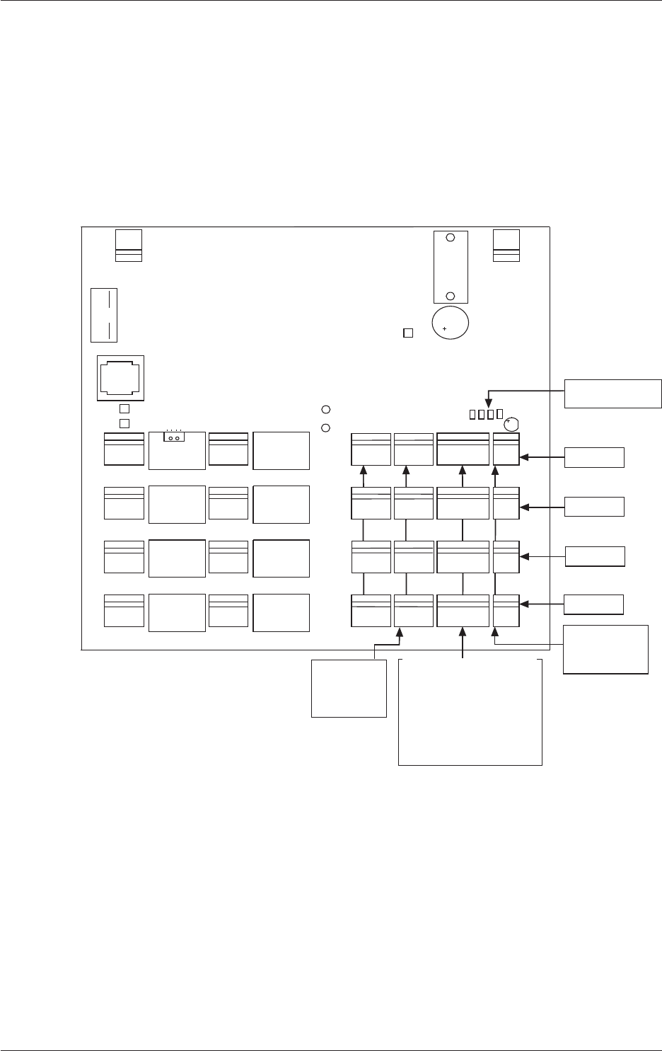
ConnecƟ ng to the Gallagher Controller 3000-4R or 3000-8R
The ports to which the Gallagher T10 Mifare Reader can connect are set up as
groups, as follows:
• Two groups (numbered 1 and 2) on the Controller 3000-4R, and
• Four groups (numbered 1 to 4) on the Controller 3000-8R
Each group provides connec on for two Gallagher T10 Mifare Readers. Refer to the
following diagram for the loca on of the ports on the Gallagher Controller 3000-8R.
81
OPEN
COMM
NCNO
COIL
COMM
NCNO
COIL
COMM
NCNO
COIL
COMM
NCNO
COIL
COMM
NCNO
COIL
COMM
NCNO
COIL
COMM
NCNO
COIL
COMM
NCNO
COIL
96 51
P4
HAMILTON, NEW ZEALAND
GGL ASSY 2A0203
GGL PCB 2M8170-0
CDX PCB 22920 V0 (c)2002 CARDAX (INTERNATIONAL) LTD
P3 P1
COMA
P2
SW
P4
PF4
PF3
PF2
PE4
PE3
PE2
COM COM COMCOM
NO NO NO NO
NC NC NC NC
COM COMCOM COM
NO NO NO NO
NC NC NC NC
PF1 PE1
P1
0V
VIN
COMB
2
3
1
2
3
1
2
3
1
2
3
1
2
3
1
2
3
1
2
3
1
2
3
1
2
1
1
2
DETECTOR
LED
RS485
POWER
IN
J4
J3
J2
J1
0V 0V 0V 0V
VOUT VOUT VOUT VOUT
PA4
PA3
PA2
PA1
2
1
2
1
2
1
2
1
PA4
POWER
OUT
PA3
POWER
OUT
PA2
POWER
OUT
PA1
POWER
OUT
COMB
OUT2
COMA
OUT1
DATA1 DATA1 DATA1 DATA1
DATA0 DATA0 DATA0 DATA0
PB4
PB3
PB2
PB1
2
3
1
4
2
3
1
4
2
3
1
4
2
3
1
4
COMA
OUT1 COMA
OUT1 COMA
OUT1
COMB
OUT2 COMB
OUT2 COMB
OUT2
2
3
1
IN2 IN2 IN2 IN2
GND
IN1 IN1 IN1 IN1
PC4
PC3
PC2
PC1
2
3
1
2
3
1
2
3
1
GND GND GND
IN4 IN4 IN4 IN4
GND
IN1 IN1 IN1 IN1
PD4
PD3
PD2
PD1
2
3
1
2
3
1
2
3
1
GNDGND GND
PC1
PC2
PC3
PC4PD4
PD3
PD2
PD1
PA1 to PA4
Power Out
pin 1 = power out
pin 2 = 0 V
Group 4
Group 3
Group 2
Group 1
PB1 to PB4
2 x Cardax IV Readers
per connector
Reader 1 = pins 1 & 3
Reader 2 = pins 2 & 4
Pin 1 = Reader 1 transmit
Pin 2 = Reader 2 transmit
Pin 3 = Reader 1 receive
Pin 4 = Reader 2 receive
J1 to J4
RS485
terminating resistors
PC1 to PC4
Inputs
pin 1 = Input 1
pin 2 = Ground
pin 3 = Input 2
Page 8
Gallagher T10 Mifare Reader
Edi on 8 | Part Number: 3E2453
November 2012
Installa on Note
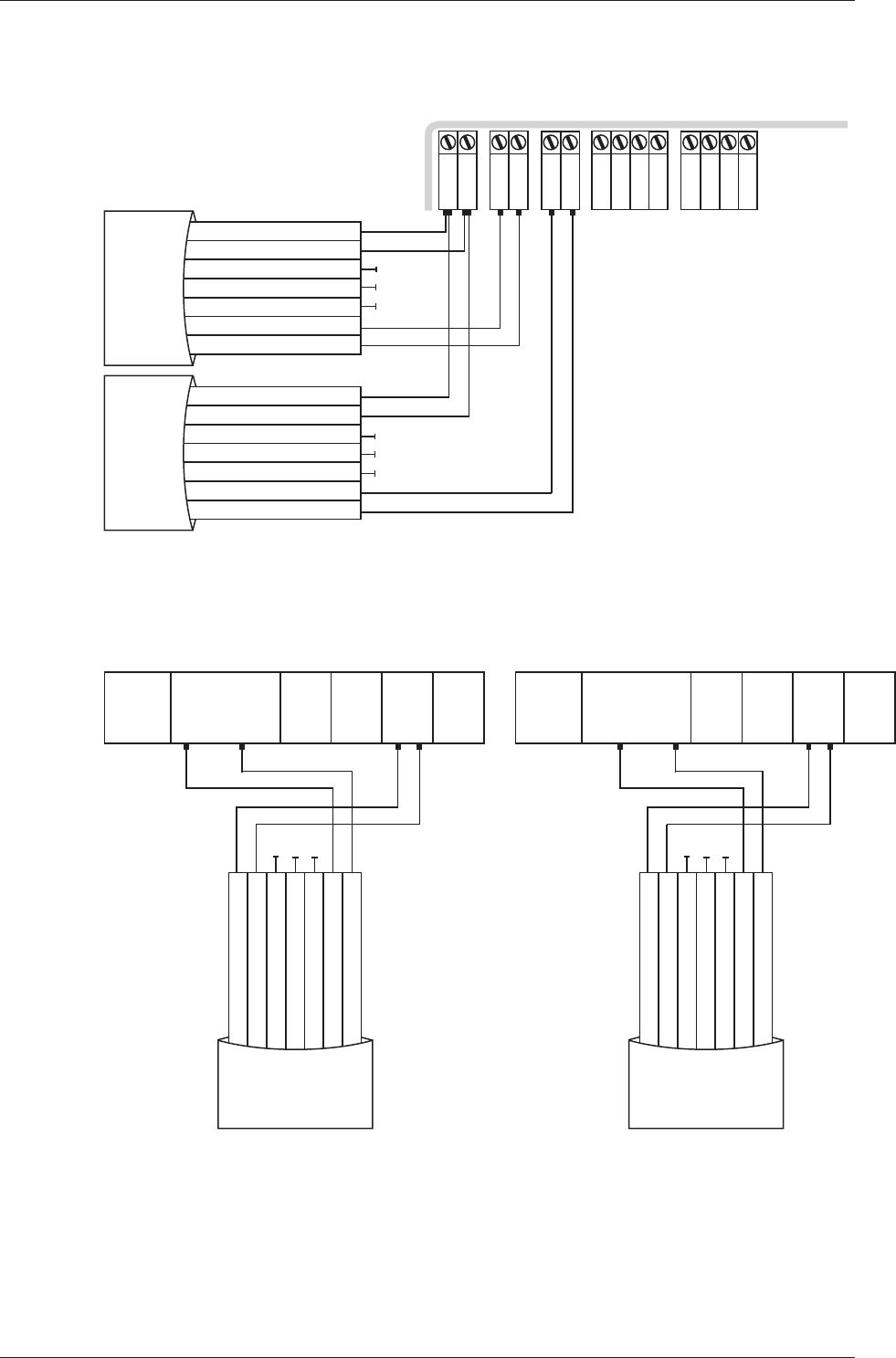
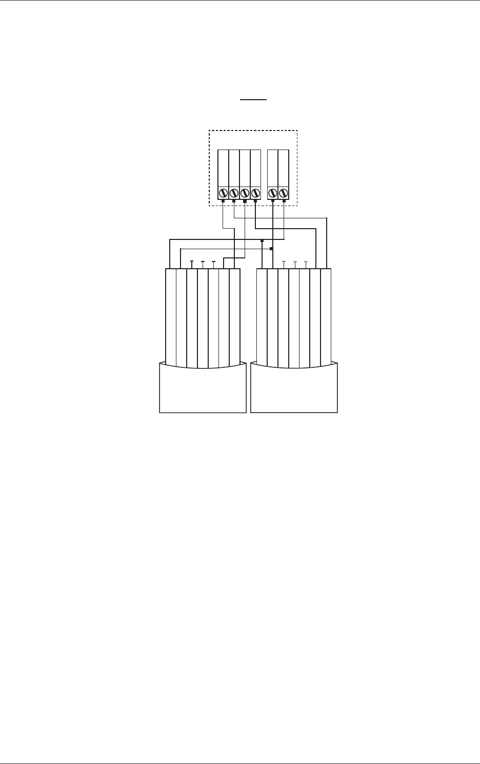
Make the connec ons from the Gallagher T10 Mifare Reader to either the Gallagher
Controller 3000-4R or 3000-8R as shown:
PB1 and PA1... to... PB2 and PA2 (3000-4R)
PB4 and PA4 (3000-8R)
Gallagher Controller 3000-4R or 3000-8R
Group
1 V OUT
2 0 V
1 DATA 0
2 DATA 1
3 OUT 1
4 OUT 2
PB PA
Posi ve Red
Nega ve Black
Reserved Orange
Reserved Green
Reserved Brown
CDXIV TX White
CDXIV RX Blue
Cardax IV Reader
Posi ve Red
Nega ve Black
Reserved Orange
Reserved Green
Reserved Brown
CDXIV TX White
CDXIV RX Blue
Cardax IV Reader
Note: Within each group, you cannot mix Cardax IV Readers with Wiegand Readers.
This is because connec ng one Wiegand Reader requires all four pins on plug PB.
For example, if you connect a Cardax IV Reader to Port 1 of Group 1, Port 2 of Group
1 can only connect to another Cardax IV Reader.
Page 9
Gallagher T10 Mifare Reader
Installa on Note
Part Number: 3E2453 | Edi on 8
November 2012
Technical Specifi caƟ ons
Technical Specifi caƟ ons
Rou ne maintenance: Not applicable for this reader.
Cleaning: This reader should only be cleaned with a clean, lint free,
damp cloth.
Power required: Voltage: 9 Vdc - 16 Vdc
Current (at 12 Vdc): 82 mA (standby)
115 mA (peak)
Environmental: Temperature Range: -35 °C to +70 °C
Note: Direct sunlight may increase the internal reader
temperature above the ambient temperature level.
Humidity: 95% non-condensing
Environmental Protec on: IP68
Impact Ra ng: IK07
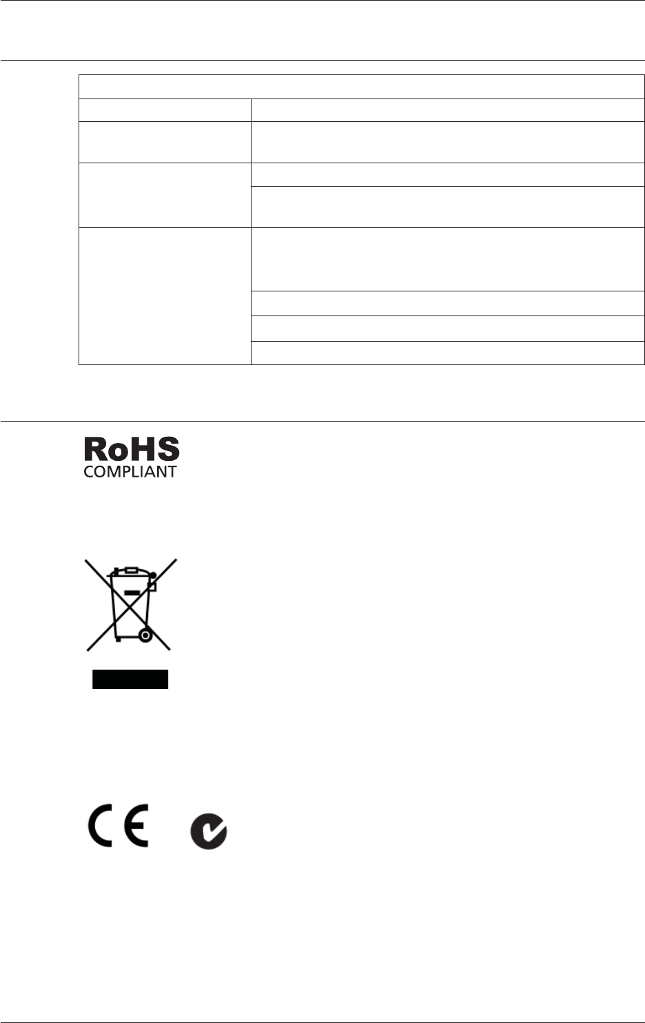
Approvals and Standards
This product complies with the environmental regula ons for the
Restric on of Hazardous Substances in electrical and electronic
equipment (RoHS). The RoHS direc ve prohibits the use of
electronic equipment containing certain hazardous substances in
the European Union.
This symbol on the product or its packaging indicates that this
product must not be disposed of with other waste. Instead, it
is your responsibility to dispose of your waste equipment by
handing it over to a designated collec on point for the recycling
of waste electrical and electronic equipment. The separate
collec on and recycling of your waste equipment at the me of
disposal will help conserve natural resources and ensure that
it is recycled in a manner that protects human health and the
environment. For more informa on about where you can drop
off your waste equipment for recycling, please contact your local
city recycling offi ce or the dealer from whom you purchased the
product.
ACN 002 132 943

Page 10
Gallagher T10 Mifare Reader
Edi on 8 | Part Number: 3E2453
November 2012
Installa on Note
FCC This device complies with part 15 of the FCC Rules. Opera on
is subject to the following two condi ons: (1) This device may
not cause harmful interference, and (2) this device must accept
any interference received, including interference that may cause
undesired opera on.
Note: This equipment has been tested and found to comply
with the limits for a Class B digital device, pursuant to part
15 of the FCC Rules. These limits are designed to provide
reasonable protec on against harmful interference in a
residen al installa on. This equipment generates, uses and can
radiate radio frequency energy and, if not installed and used in
accordance with the instruc ons, may cause harmful interference
to radio communica ons. However, there is no guarantee that
interference will not occur in a par cular installa on. If this
equipment does cause harmful interference to radio or television
recep on, which can be determined by turning the equipment off
and on, the user is encouraged to try to correct the interference
by one or more of the following measures:
- Reorient or relocate the receiving antenna.
- Increase the separa on between the equipment and receiver.
- Connect the equipment into an outlet on a circuit diff erent from
that to which the receiver is connected.
- Consult the dealer or an experienced radio/TV technician for
help.
Industry
Canada
This device complies with Industry Canada licence-exempt RSS
standard(s). Opera on is subject to the following two condi ons:
(1) this device may not cause interference, and (2) this device
must accept any interference, including interference that may
cause undesired opera on of the device.
Note: Changes or modifi ca ons not expressly approved by
Gallagher Group Limited could void the user’s authority to
operate this equipment.
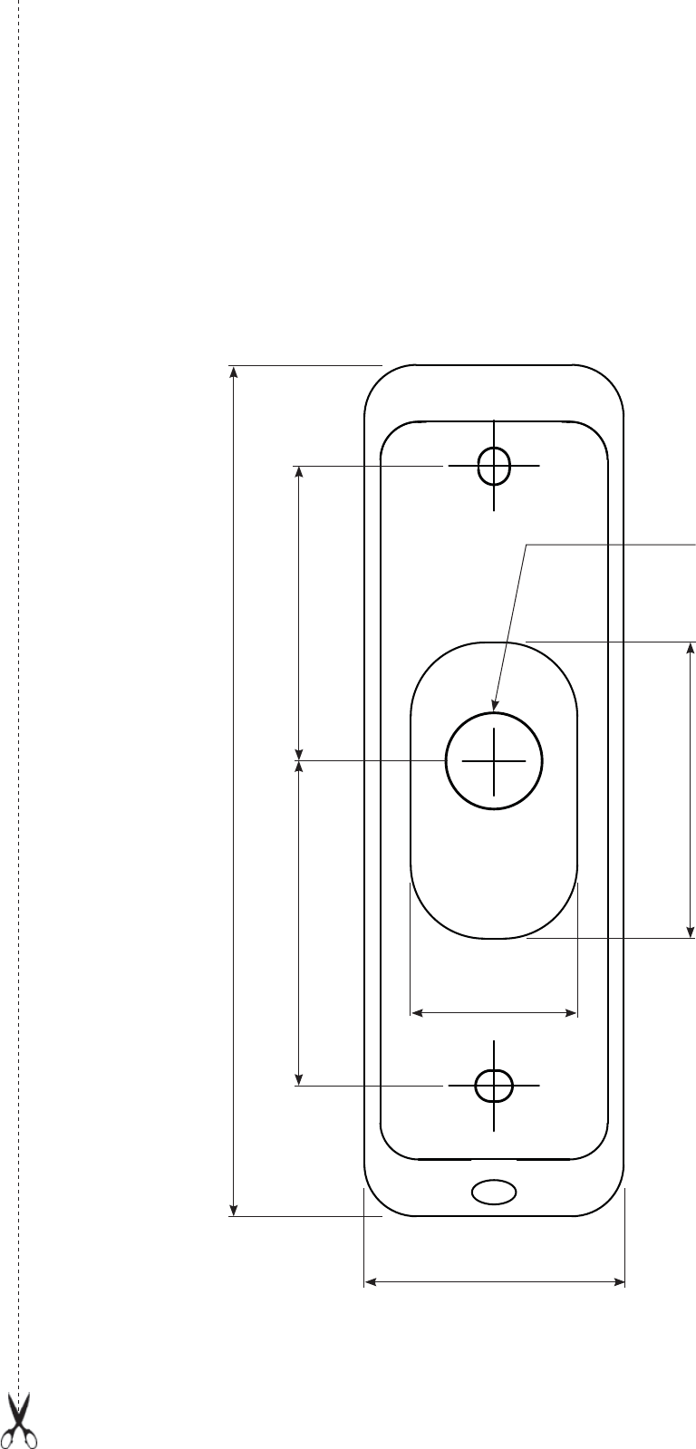
Drill Template
115 mm (4.53 inches)
35 mm (1.38 inches)
44 mm (1.73 inches) 40 mm (1.57 inches)
13 mm (1/2 inch) diameter
hole for cable
22.5 mm
(0.89 inches)
40 mm (1.57 inches)