Gallagher Group C30044X Prox Readers T11 Multi Tech and T12 Multi Tech User Manual 3E2513 Gallagher T11 Reader Ins Note R10 indd
Gallagher Group Ltd Prox Readers T11 Multi Tech and T12 Multi Tech 3E2513 Gallagher T11 Reader Ins Note R10 indd
Contents
- 1. Users Manual T11
- 2. Users Manual T12
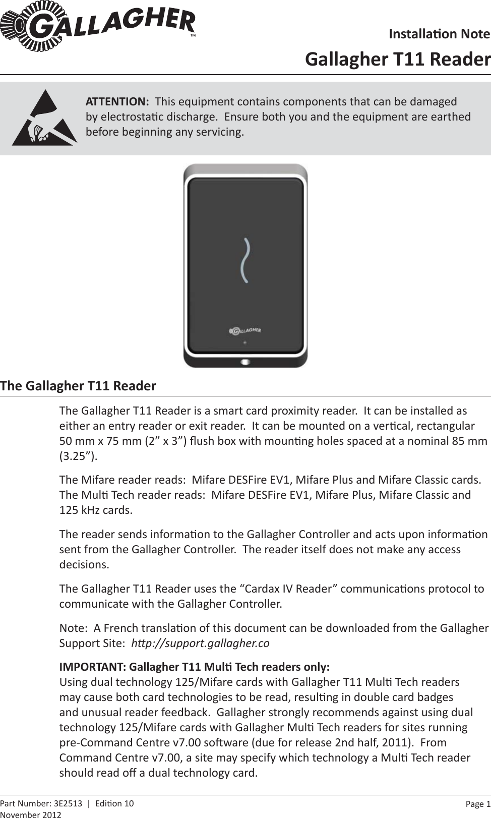
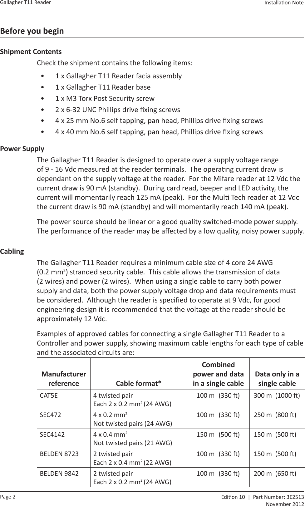
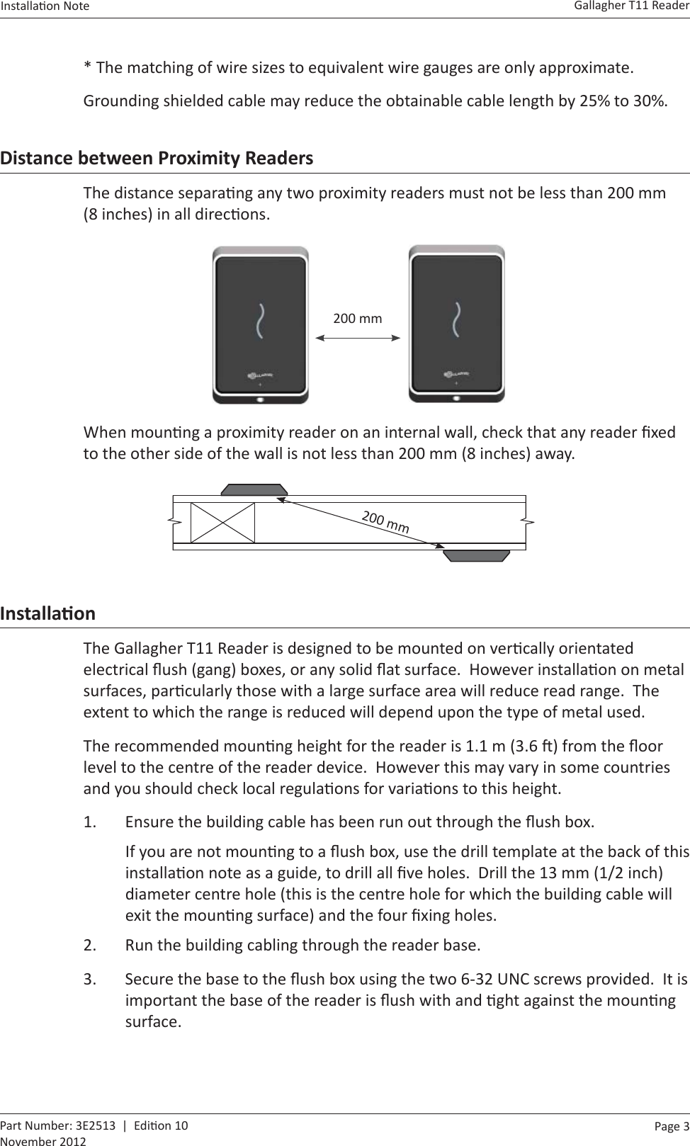
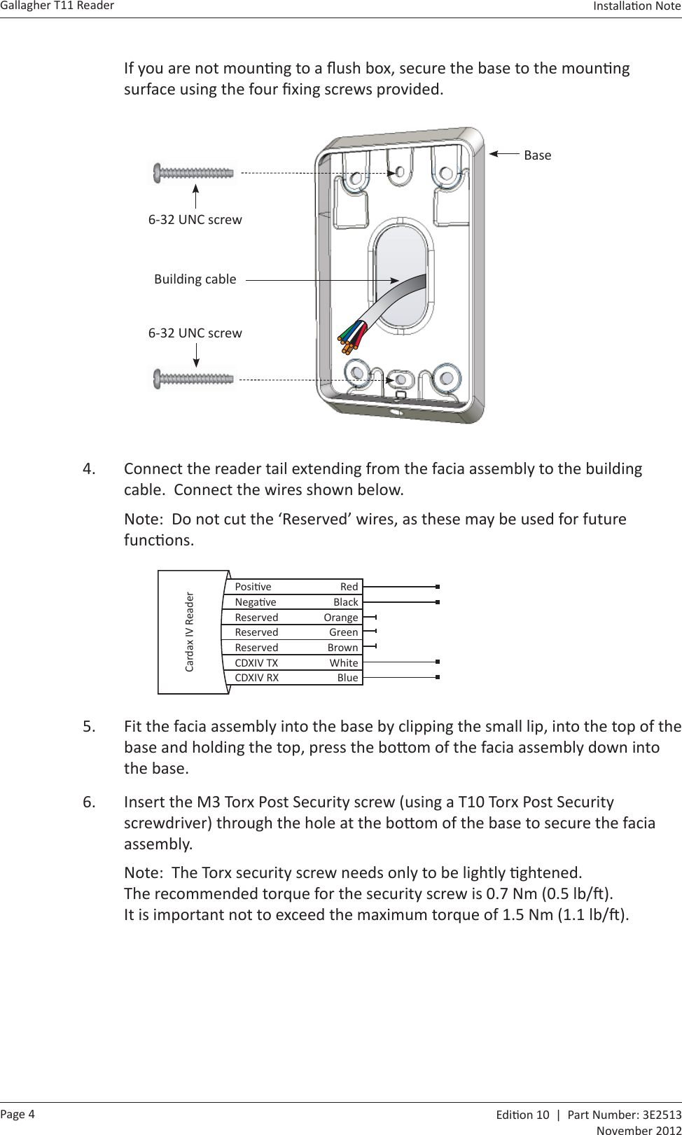
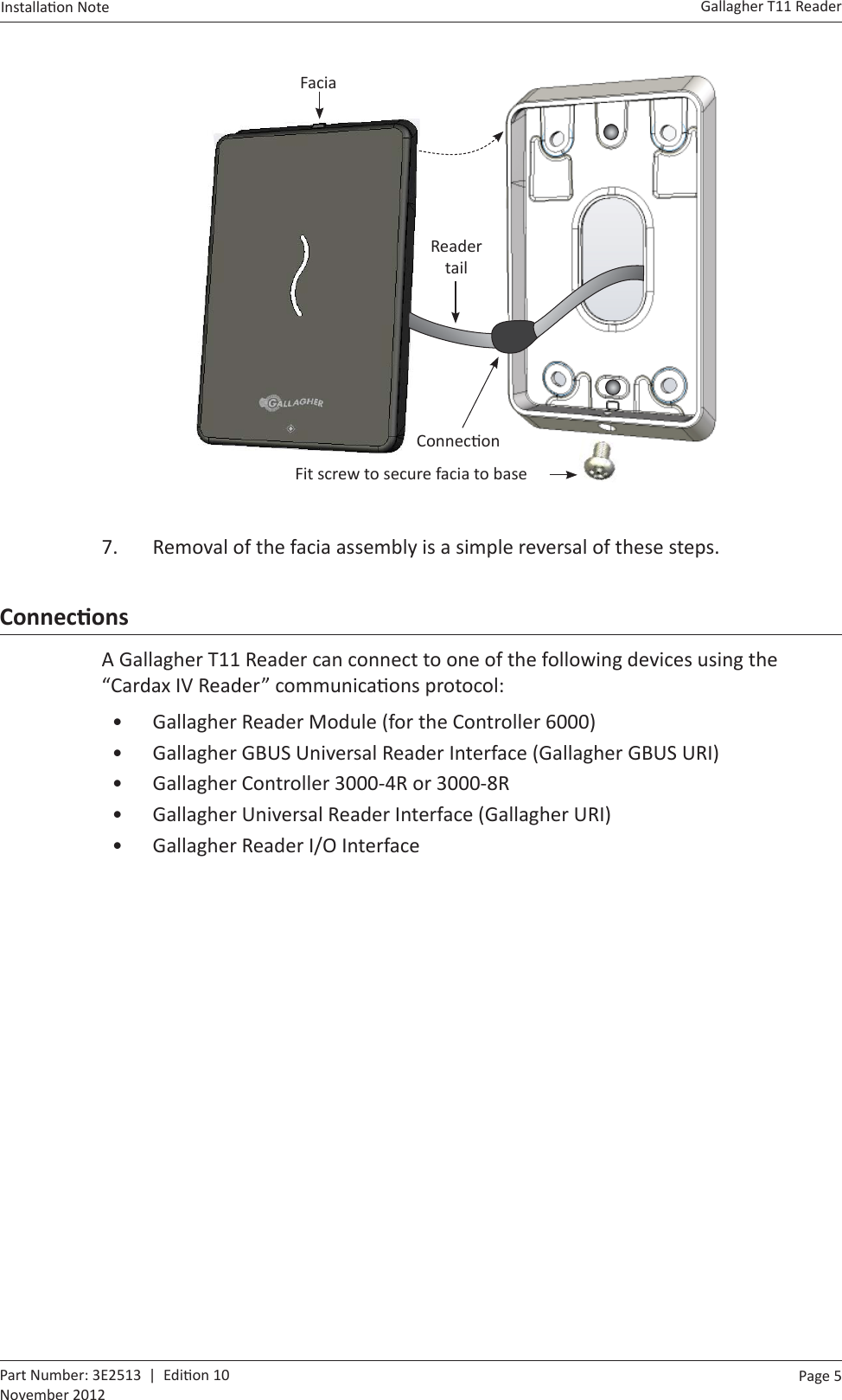
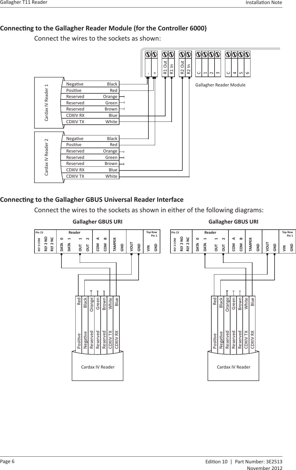
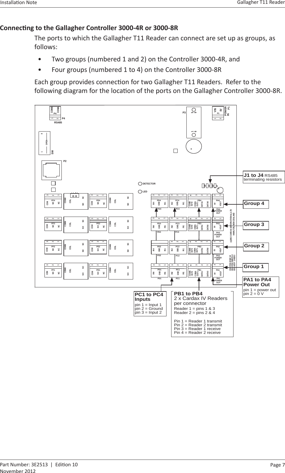
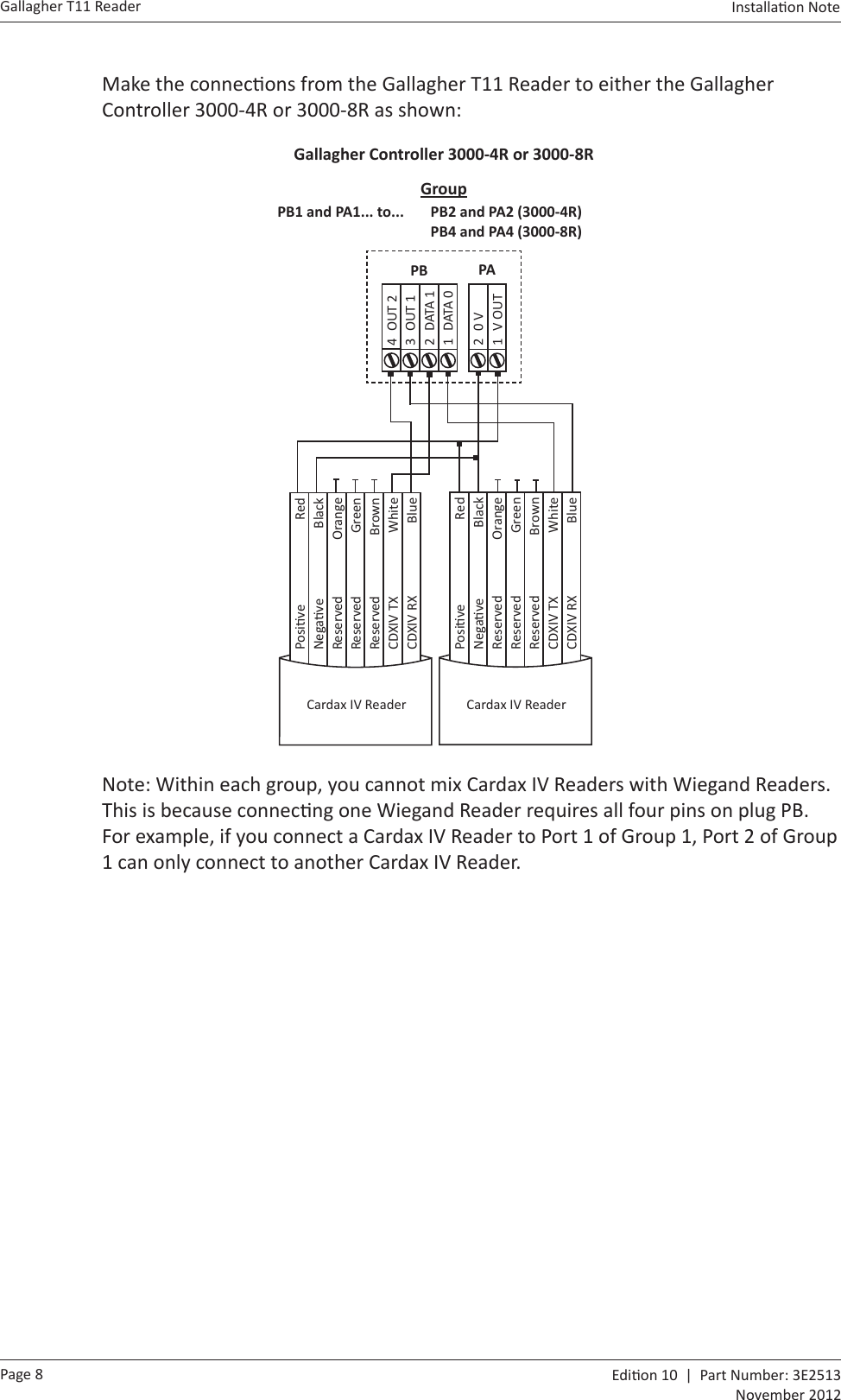
Users Manual T11