Gallagher Group C30046X Prox Reader T20 Multi Tech User Manual
Gallagher Group Ltd Prox Reader T20 Multi Tech Users Manual
Users Manual
Page 1
Document Code: 3E3140
Edion 3, April 2013
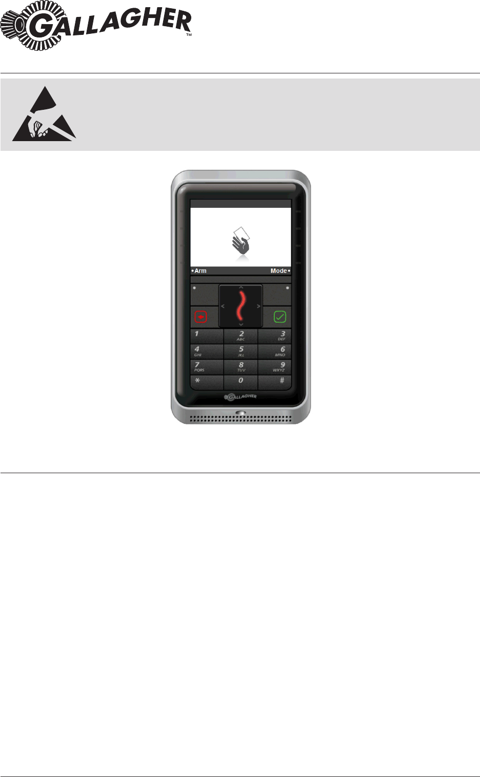
The Gallagher T20 Reader
The Gallagher T20 Reader is a smart card proximity reader. The reader can be
installed as either an entry reader or an exit reader.
The reader can be mounted on a rectangular 50 mm x 75 mm (2” x 3”) ush box, BS
4662 Brish Standard square ush box, or any solid at surface.
The Mifare reader reads: Mifare DESFire EV1, Mifare Plus and Mifare Classic cards.
The Mul Tech reader reads: Mifare DESFire EV1, Mifare Plus, Mifare Classic and 125
KHz cards.
The reader sends informaon to the Gallagher Controller and acts upon informaon
sent from the Gallagher Controller. The reader itself does not make any access
decisions.
The reader uses the Cardax IV communicaons protocol to communicate with the
Gallagher Controller. Refer to the “Connecons” topic later in this note, for details
regarding Cardax IV Reader connecons.
ATTENTION: This equipment contains components that can be damaged
by electrostac discharge. Ensure both you and the equipment are earthed
before beginning any servicing.
Installaon Note
Gallagher T20 Reader

Page 2
Gallagher T20 Reader
Document Code: 3E3140
Edion 3, April 2013
Installaon Note
IMPORTANT: Gallagher T20 Mul Tech readers only:
Using dual technology 125/Mifare cards with Gallagher T20 Mul Tech readers
may cause both card technologies to be read, resulng in double card badges
and unusual reader feedback. Gallagher strongly recommends against using dual
technology 125/Mifare cards with Gallagher Mul Tech readers for sites running
pre-Command Centre v7.00 soware. From Command Centre v7.00, a site may
specify which technology a Mul Tech reader should read o a dual technology
card.
Before you begin
Shipment Contents
Check the shipment contains the following items:
• 1 x Gallagher T20 Reader facia assembly
• 1 x Gallagher T20 Reader base
• 2 x 6-32 UNC Phillips drive xing screws
• 2 x M3.5 Phillips drive xing screws
• 5 x 25 mm No.6 self tapping, pan head, Phillips drive xing screws
• 5 x 40 mm No.6 self tapping, pan head, Phillips drive xing screws
• 1 x M3 Torx Post (T10) Security screw
Power Supply
The Gallagher T20 Reader is designed to operate over a supply voltage range
of 9 - 16 Vdc measured at the reader terminals. The operang current draw is
dependent on the supply voltage at the reader. For the Mifare reader, at 12 Vdc
the current draw is 90 mA (standby). During card read, beeper and LED acvity, the
current will momentarily reach 125 mA (peak). For the Mul Tech reader, at 12 Vdc
the current draw is 90 mA (standby) and will momentarily reach 140 mA (peak).
The power source should be linear or a good quality switched-mode power supply.
The performance of the reader may be aected by a low quality, noisy power supply.
Cabling
The Gallagher T20 Reader requires a minimum cable size of 4 core
24 AWG (0.2 mm2) stranded security cable. This cable allows the transmission of
data (2 wires) and power (2 wires). When using a single cable to carry both power
supply and data, both the power supply voltage drop and data requirements must
be considered. Although the reader is specied to operate at 9 Vdc, for good
engineering design it is recommended that the voltage at the reader should be
approximately 12 Vdc.
Examples of approved cables for connecng a single Gallagher T20 Reader to a
Controller and power supply, showing maximum cable lengths for each type of cable
and the associated circuits are:
Page 3
Gallagher T20 Reader
Installaon Note
Document Code: 3E3140
Edion 3, April 2013
Cable type Cable format*
Single reader
connected
using data only
in a single cable
Single reader
connected using
power and data
in a single cable
CAT 5e or beer 4 twisted pair
Each 2 x 0.2 mm2 (24 AWG)
200 m (650 ) 100 m (330 )
BELDEN 9842
(shielded)
2 twisted pair
Each 2 x 0.2 mm2 (24 AWG)
200 m (650 ) 100 m (330 )
SEC472 4 x 0.2 mm2
Not twisted pairs (24 AWG)
200 m (650 ) 100 m (330 )
SEC4142 4 x 0.4 mm2
Not twisted pairs (21 AWG)
200 m (650 ) 150 m (500 )
* The matching of wire sizes to equivalent wire gauges are only approximate.
Notes:
• Shielded cable may reduce the obtainable cable length. Shielded cable should
be grounded at the Controller end only.
• If other cable types are used, operang distances and performance may be
reduced depending on the cable quality.
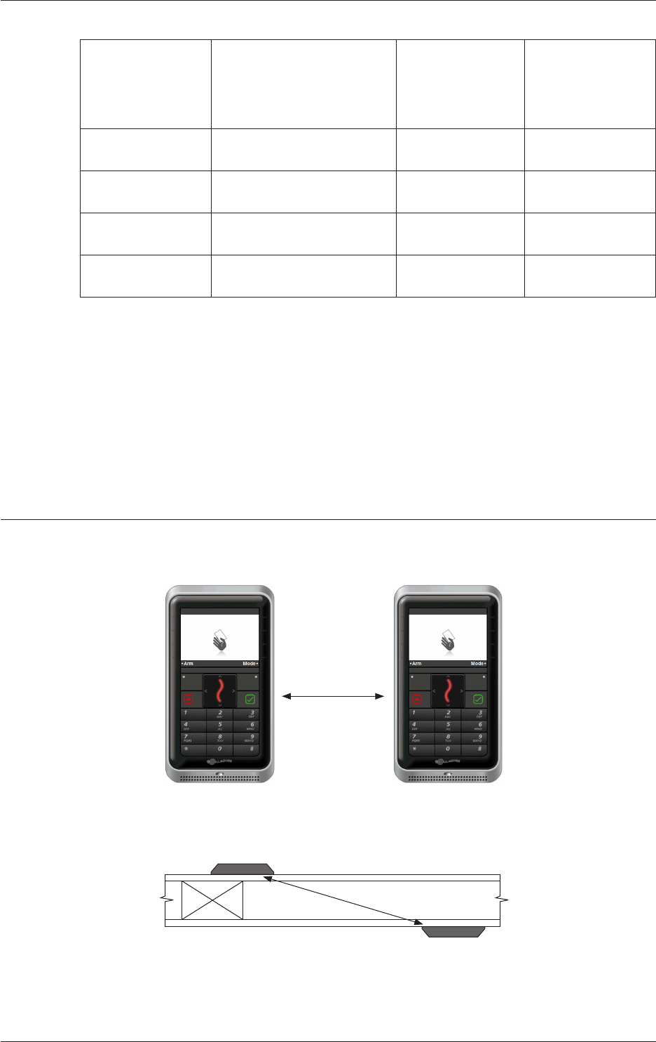
Distance between Proximity Readers
The distance separang any two proximity readers must not be less than 200 mm
(8 inches) in all direcons.
200 mm
When mounng a proximity reader on an internal wall, check that any reader xed
to the other side of the wall is not less than 200 mm (8 inches) away.
200 mm

Page 4
Gallagher T20 Reader
Document Code: 3E3140
Edion 3, April 2013
Installaon Note
Installaon
The Gallagher T20 Reader can be mounted on:
• a vercal, rectangular 50 mm x 75 mm (2” x 3”) ush box
• a BS 4662 Brish Standard square ush box
• any solid at surface
The recommended mounng height for the reader is 1.1 m (3.6 ) from the oor
level to the centre of the reader device. However this may vary in some countries
and you should check local regulaons for variaons to this height.
Notes:
• Installaon on metal surfaces, parcularly those with a large surface area
will reduce read range. The extent to which the range is reduced will depend
upon the type of metal surface.
• When mounng on a ush box, the corner screws must be used as well as the
ush box screws. Without corner screws the top of the product is vulnerable
to seperaon from the wall.
• The reader cannot be mounted on a mounng block.
1. Ensure the building cable has been run out through the ush box.
If you are not mounng to a ush box, use the reader base as a guide, to drill
all ve holes. Drill the 13 mm (1/2 inch) diameter centre hole (this is the
centre hole for which the building cable will exit the mounng surface) and
the four corner xing holes. Ensure the centre hole allows the cable to run
freely out through the mounng surface, so that the reader facia can clip into
the base.
Note: There is no room for the building cable to be scrunched into the reader
base. The building cable must remain within the ush box or wall cavity.
2. Run the building cable through the reader base.
Note: If the reader has already been connected to the building cable, you can
pass the facia through the base. Great care must be taken to avoid scratching
the screen and keypad when passing the facia through the base.
3. Secure the base to the ush box using the two screws provided. When
securing the base to a vercal, rectangular ush box, use the 6-32 UNC screws
provided. When securing the base to a BS 4662 Brish Standard square ush
box, use the M3.5 screws provided.
4. Drill pilot holes for the four corner xing holes. Secure the base to the
mounng surface using the four corner xing screws provided. It is important
the four corner xing screws are used to ensure the reader is ush with and
ght against the mounng surface.
Note: It is strongly recommended that you use the screws provided. If an
alternave screw is used, the head must be no larger nor deeper than that of
the screw provided.
Page 5
Gallagher T20 Reader
Installaon Note
Document Code: 3E3140
Edion 3, April 2013
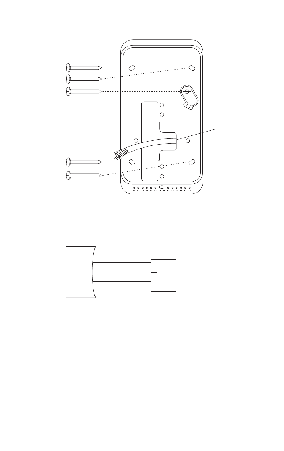
5. Secure the tamper tab (located in the base) to the mounng surface using
remaining xing screw provided.
Base
Building cable
No. 6 pan head screw
Tamper tab
6. Connect the reader tail extending from the facia assembly to the building
cable. Connect the wires, as shown in the following diagram.
Note: Do not cut the “Reserved” wires, as they may be used for future
funcons.
Posive Red
Negave Black
Reserved Orange
Reserved Green
Reserved Brown
CDXIV TX White
CDXIV RX Blue
Cardax IV Reader
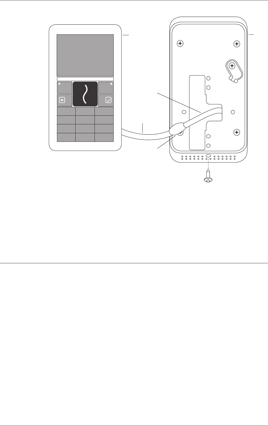
7. Fit the facia assembly into the base by clipping the small lip, into the top of the
base and holding the top, press the boom of the facia assembly down into
the base.
8. Insert the M3 Torx Post Security screw (using a T10 Torx Post Security
screwdriver) through the hole at the boom of the base to secure the facia
assembly.
Note: The Torx Post Security screw needs only to be lightly ghtened.
The recommended torque for the security screw is 0.7 Nm (0.5 lb/). It is
important not to exceed the maximum torque of 1.5 Nm (1.1 lb/).
Page 6
Gallagher T20 Reader
Document Code: 3E3140
Edion 3, April 2013
Installaon Note
Base
Facia
Fit T10 Torx Post screw to
secure facia to base
Building cable
Reader tail
Connecon
9. Removal of the facia assembly is a simple reversal of these steps.
Note: If it is dicult to remove the facia from the base, a tab can be fashioned
using a piece of gaer tape. Sck the tab to the facia (over the Gallagher logo)
and use it to pull the facia out of the base, then remove the tape without
leaving a mark.
Connecons
The Gallagher T20 Reader can be connected as a Cardax IV Reader to one of the
following devices:
• Gallagher Reader Module 8R or 4R (aached to the Controller 6000)
• Gallagher GBUS Universal Reader Interface (Gallagher GBUS URI)
• Gallagher Controller 3000-8R or 3000-4R
• Gallagher Local Bus Universal Reader Interface (Gallagher URI)
• Gallagher Local Bus Reader I/O Interface
Page 7
Gallagher T20 Reader
Installaon Note
Document Code: 3E3140
Edion 3, April 2013
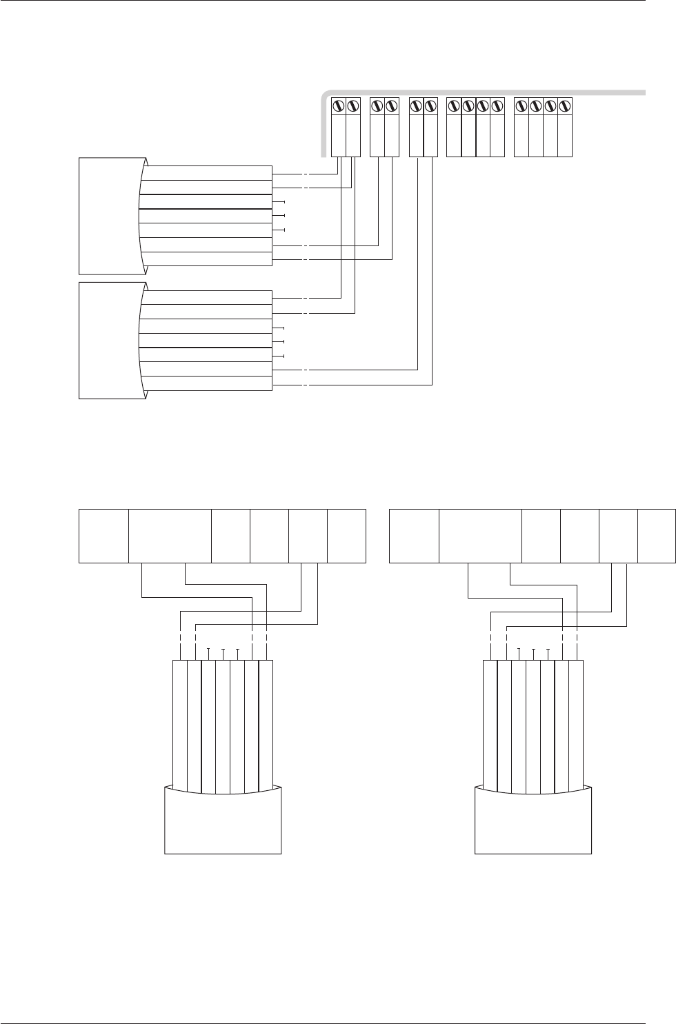
Gallagher Reader Module 8R or 4R (aached to the Controller 6000)
Connect the wires to the sockets as shown:
-
+
R1 Out
R1 In
C
1
2
3
C
4
5
6
R2 Out
R2 In
Gallagher Reader Module
Negave Black
Posive Red
Reserved Orange
Reserved Green
Reserved Brown
CDXIV RX Blue
CDXIV TX White
Cardax IV Reader 1
Negave Black
Posive Red
Reserved Orange
Reserved Green
Reserved Brown
CDXIV RX Blue
CDXIV TX White
Cardax IV Reader 2
Gallagher GBUS Universal Reader Interface (Gallagher GBUS URI)
Connect the wires to the sockets as shown in either of the following diagrams:
RLY 2 COM
RLY 2 NO
RLY 2 NC
DATA 0
DATA 1
OUT 1
OUT 2
COM A
COM B
TAMPER
GND
VOUT
GND
VIN
GND
Pin 15 Reader Top Row
Pin 1
Gallagher GBUS URI
Posive Red
Negave Black
Reserved Orange
Reserved Green
Reserved Brown
CDXIV TX White
CDXIV RX Blue
Cardax IV Reader
RLY 2 COM
RLY 2 NO
RLY 2 NC
DATA 0
DATA 1
OUT 1
OUT 2
COM A
COM B
TAMPER
GND
VOUT
GND
VIN
GND
Pin 15 Reader Top Row
Pin 1
Gallagher GBUS URI
Posive Red
Negave Black
Reserved Orange
Reserved Green
Reserved Brown
CDXIV TX White
CDXIV RX Blue
Cardax IV Reader
Page 8
Gallagher T20 Reader
Document Code: 3E3140
Edion 3, April 2013
Installaon Note
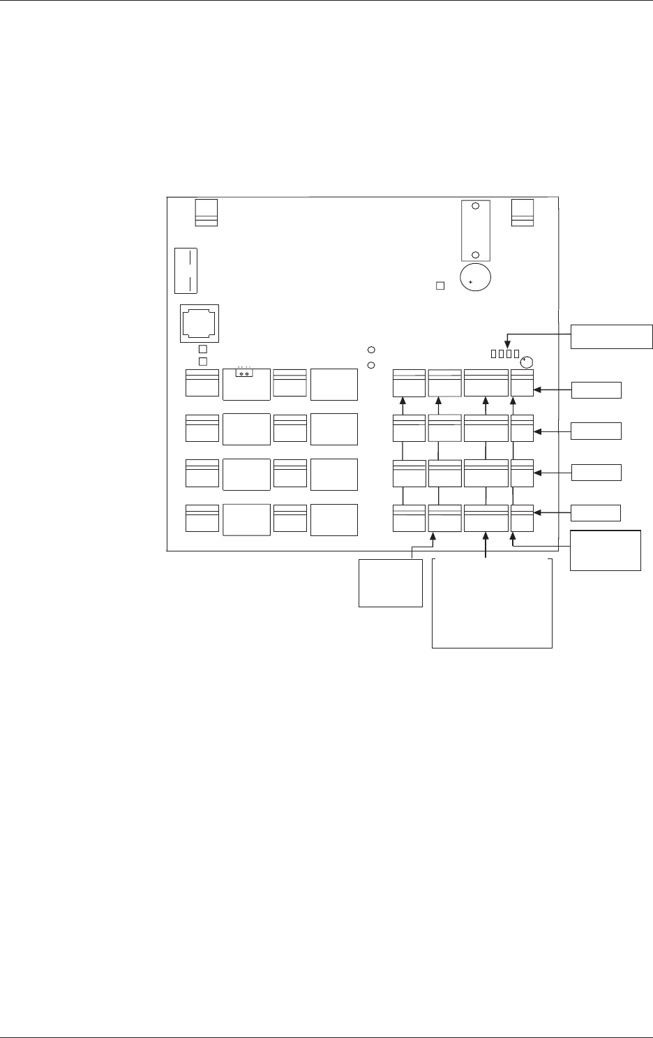
Gallagher Controller 3000-8R or 3000-4R
The ports to which the Gallagher T20 Reader can connect are set up as groups:
• Four groups (numbered 1 to 4) on the Controller 3000-8R, and
• Two groups (numbered 1 and 2) on the Controller 3000-4R
Each group provides connecon for two readers. Refer to the following diagram for
the locaon of the ports on the Controller 3000-8R.
81
OPEN
COMM
NCNO
COIL
COMM
NCNO
COIL
COMM
NCNO
COIL
COMM
NCNO
COIL
COMM
NCNO
COIL
COMM
NCNO
COIL
COMM
NCNO
COIL
COMM
NCNO
COIL
96
51
P4
HAMILTON, NEW ZEALAND
GGL ASSY 2A0203
GGL PCB 2M8170-0
CDX PCB 22920 V0 (c)2002 CARDAX (INTERNATIONAL) LTD
P3
P1
COMA
P2
SW
P4
PF4
PF3
PF2
PE4
PE3
PE2
COMCOMCOMCOM
NO NO NO NO
NC NC NC NC
COMCOMCOMCOM
NO NO NO NO
NC NC NC NC
PF1PE1
P1
0V
VIN
COMB
2
3
1
2
3
1
2
3
1
2
3
1
2
3
1
2
3
1
2
3
1
2
3
1
2
1
1
2
DETECTOR
LED
RS485
POWER
IN
J4
J3
J2
J1
0V 0V 0V 0V
VOUT VOUT VOUT VOUT
PA4
PA3
PA2
PA1
2
1
2
1
2
1
2
1
PA4
POWER
OUT
PA3
POWER
OUT
PA2
POWER
OUT
PA1
POWER
OUT
COMB
OUT2
COMA
OUT1
DATA1DATA1 DATA1DATA1
DATA0DATA0 DATA0DATA0
PB4
PB3
PB2
PB1
2
3
1
4
2
3
1
4
2
3
1
4
2
3
1
4
COMA
OUT1 COMA
OUT1
COMA
OUT1
COMB
OUT2
COMB
OUT2
COMB
OUT2
2
3
1
IN2IN2 IN2IN2
GND
IN1IN1 IN1IN1
PC4
PC3
PC2
PC1
2
3
1
2
3
1
2
3
1
GNDGNDGND
IN4IN4 IN4IN4
GND
IN1IN1 IN1IN1
PD4
PD3
PD2
PD1
2
3
1
2
3
1
2
3
1
GNDGNDGND
PC1
PC2
PC3
PC4PD4
PD3
PD2
PD1
PA1 to PA4
Power Out
pin 1 = power out
pin 2 = 0 V
Group 4
Group 3
Group 2
Group 1
PB1 to PB4
2 x Cardax IV Readers
per connector
Reader 1 = pins 1 & 3
Reader 2 = pins 2 & 4
Pin 1 = Reader 1 transmit
Pin 2 = Reader 2 transmit
Pin 3 = Reader 1 receive
Pin 4 = Reader 2 receive
J1 to J4
RS485
terminating resistors
PC1 to PC4
Inputs
pin 1 = Input 1
pin 2 = Ground
pin 3 = Input 2
Page 9
Gallagher T20 Reader
Installaon Note
Document Code: 3E3140
Edion 3, April 2013
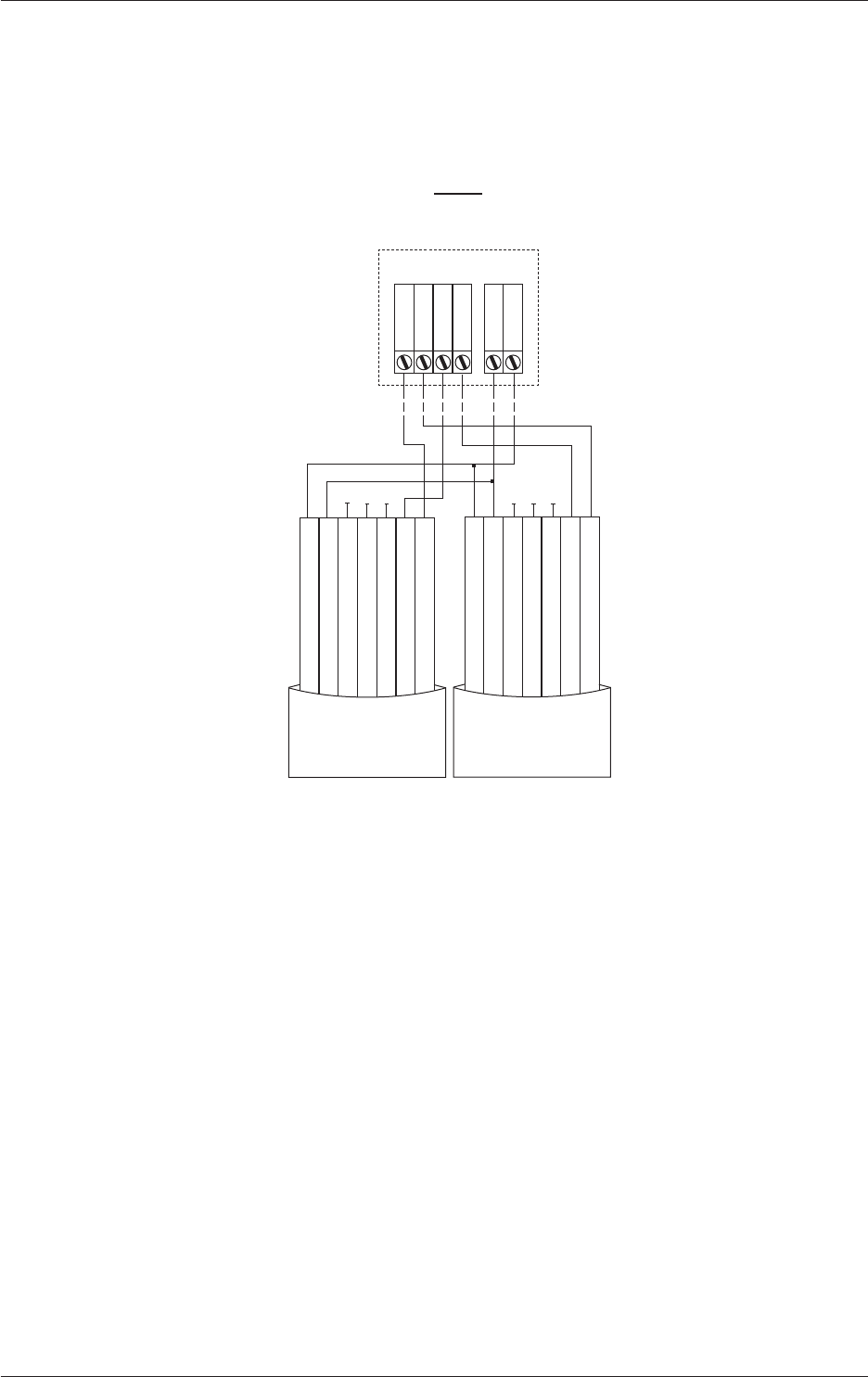
Make the connecons from the reader to either the Controller 3000-8R or 3000-4R
as shown:
PB1 and PA1... to... PB4 and PA4 (3000-8R)
PB2 and PA2 (3000-4R)
Gallagher Controller 3000-8R or 3000-4R
Group
1 V OUT
2 0 V
1 DATA 0
2 DATA 1
3 OUT 1
4 OUT 2
PB PA
Posive Red
Negave Black
Reserved Orange
Reserved Green
Reserved Brown
CDXIV TX White
CDXIV RX Blue
Cardax IV Reader
Posive Red
Negave Black
Reserved Orange
Reserved Green
Reserved Brown
CDXIV TX White
CDXIV RX Blue
Cardax IV Reader
Note: Within each group, you cannot mix Cardax IV Readers with Wiegand Readers.
This is because connecng one Wiegand reader requires all four pins on plug PB.
For example, if you connect a Cardax IV Reader to Port 1 of Group 1, Port 2 of Group
1 can only connect to another Cardax IV Reader.

Page 10
Gallagher T20 Reader
Document Code: 3E3140
Edion 3, April 2013
Installaon Note
HBUS LED Diagnosc Indicaons
LED Diagnosc Indicaon
3 Flash (Amber) No communicaons with the Controller.
On (Green or Red) Fully congured and funconing normally
Green = Access mode is Free
Red = Access mode is Secure
Technical Specicaons
Roune maintenance: Not applicable for this reader.
Cleaning: This reader should only be cleaned with a clean, lint free,
damp cloth.
Voltage: 9 Vdc - 16 Vdc
Current (at 12Vdc): 82 mA (standby) Mifare reader
115 mA (peak) Mifare reader
90 mA (standby) Mul Tech reader
140 mA (peak) Mul Tech reader
Temperature range: -35 °C to +70 °C
Note: Direct sunlight may increase the internal reader
temperature above the ambient temperature level.
Humidity: 85% non-condensing
Environmental protecon: IP55
Impact rang: IK04
Maximum number of
readers on one HBUS cable:
20
Page 11
Gallagher T20 Reader
Installaon Note
Document Code: 3E3140
Edion 3, April 2013
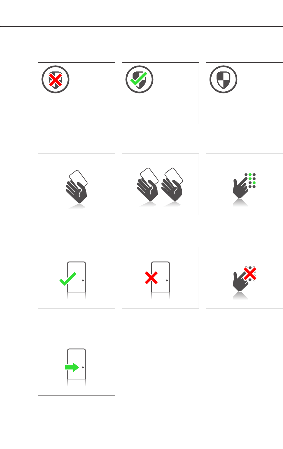
Icons
The Gallagher T20 Reader displays the following icons:
Arming Failed Arming Succeeded Armed
Present Card Present Second Card Enter PIN
Access Granted Access Denied Wrong PIN
Free Access

Page 12
Gallagher T20 Reader
Document Code: 3E3140
Edion 3, April 2013
Installaon Note
Approvals and Standards
FCC This device complies with part 15 of the FCC Rules. Operaon is subject to the
following two condions: (1) This device may not cause harmful interference,
and (2) this device must accept any interference received, including
interference that may cause undesired operaon.
Note: Changes or modicaons not expressly approved by Gallagher Limited
could void the user’s authority to operate this equipment.
Note: This equipment has been tested and found to comply with the limits
for a Class B digital device, pursuant to part 15 of the FCC Rules. These limits
are designed to provide reasonable protecon against harmful interference
in a residenal installaon. This equipment generates, uses and can radiate
radio frequency energy and, if not installed and used in accordance with
the instrucons, may cause harmful interference to radio communicaons.
However, there is no guarantee that interference will not occur in a parcular
installaon. If this equipment does cause harmful interference to radio or
television recepon, which can be determined by turning the equipment o
and on, the user is encouraged to try to correct the interference by one or
more of the following measures:
• Reorient or relocate the receiving antenna.
• Increase the separaon between the equipment and receiver.
• Connect the equipment into an outlet on a circuit dierent from that to
which the receiver is connected.
• Consult the dealer or an experienced radio/TV technician for help.
Industry
Canada
This device complies with Industry Canada licence-exempt RSS standard(s).
Operaon is subject to the following two condions: (1) this device may not
cause interference, and (2) this device must accept any interference, including
interference that may cause undesired operaon of the device.
Industrie
Canada
Le présent appareil est conforme aux CNR d’Industrie Canada applicables
aux appareils radio exempts de licence. L’exploitaon est autorisée aux deux
condions suivantes : (1) l’appareil ne doit pas produire de brouillage, et (2)
l’ulisateur de l’appareil doit accepter tout brouillage radioélectrique subi,
même si le brouillage est suscepble d’en compromere le fonconnement.
This product complies with the environmental regulaons for the Restricon
of Hazardous Substances in electrical and electronic equipment (RoHS). The
RoHS direcve prohibits the use of electronic equipment containing certain
hazardous substances in the European Union.
This symbol on the product or its packaging indicates that this product must
not be disposed of with other waste. Instead, it is your responsibility to
dispose of your waste equipment by handing it over to a designated collecon
point for the recycling of waste electrical and electronic equipment. The
separate collecon and recycling of your waste equipment at the me of
disposal will help conserve natural resources and ensure that it is recycled
in a manner that protects human health and the environment. For more
informaon about where you can drop o your waste equipment for recycling,
please contact your local city recycling oce or the dealer from whom you
purchased the product.
ETSI EN 300 330-2 V1.5.1:2010
EN50130-4:1996
ACN 002 132 943
Lead Free
Page 13
Gallagher T20 Reader
Installaon Note
Document Code: 3E3140
Edion 3, April 2013
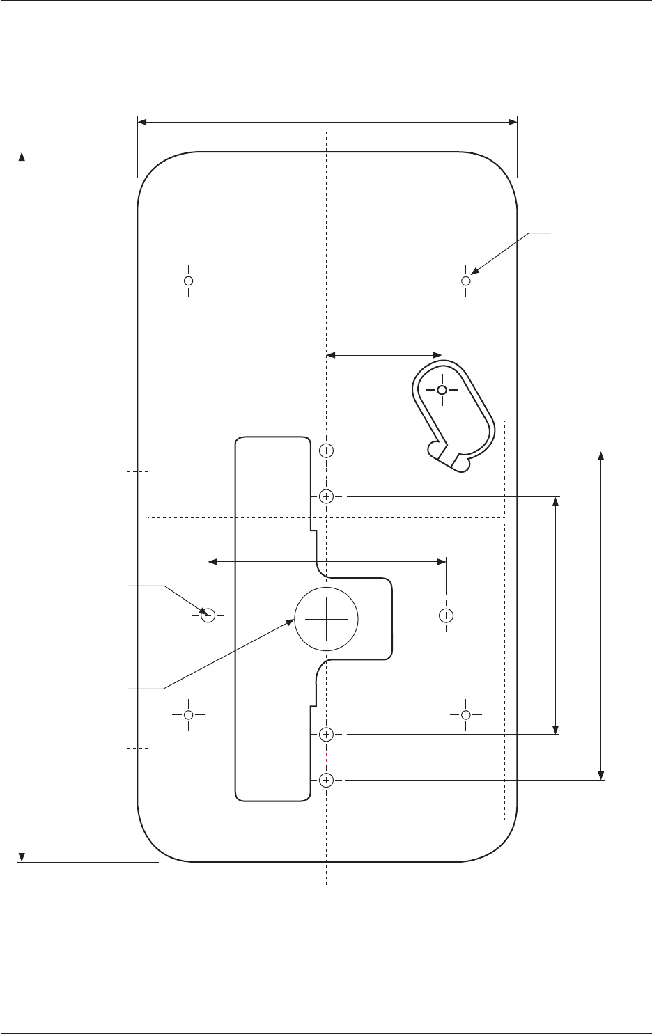
Mounng Dimensions
179.5 mm (7.07 inches)
95.7 mm (3.77 inches)
6G Screw
60.3 mm (2.37 inches)
29.1 mm
(1.14 inches)
60.3 mm (2.37 inches)
83.3 mm (2.78 inches)
Flush Box Screw
Cable Exit
125 card
read area
Mifare card
read area
IMPORTANT
This picture is not to scale, therefore use the measurements provided.