Gallagher Group G031504 Smart Reader R Series User Manual 3E0722 SmartReader R Series
Gallagher Group Ltd Smart Reader R Series 3E0722 SmartReader R Series
UserManual.wiki
>
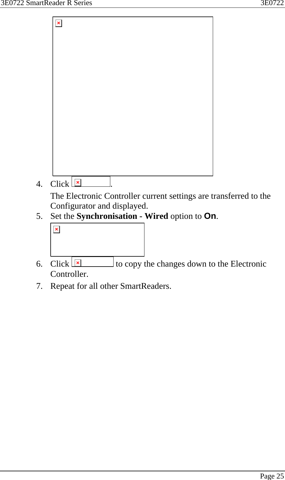
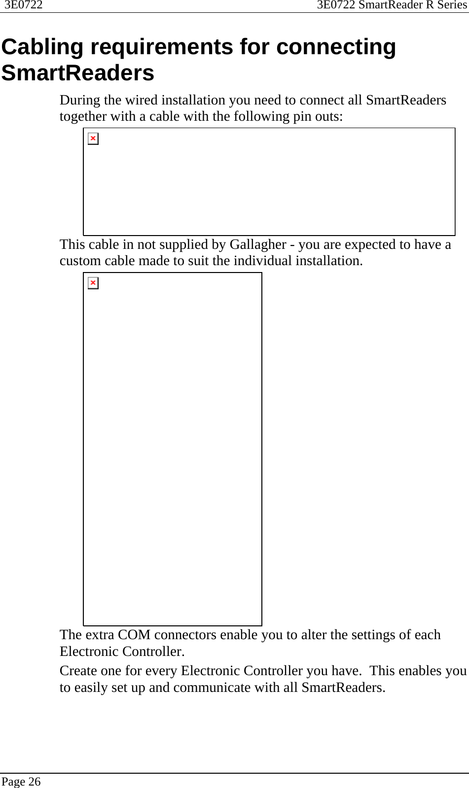
Gallagher Group
>
G031504 User Manual
Users Manual
Navigation menu
Upload a User Manual
Namespaces
Wiki Guide
HTML
PDF
Info
Views
User Manual
Discussion / Help
Navigation