Gallo Technologies GTS20210 GTSTARTER2 User Manual GTS2 Operation manual final
Gallo Technologies GTSTARTER2 GTS2 Operation manual final
Users Manual

© Copyright
Gallo Technologies
. All Right Reserved
-
1
-
10810
Operation & Installation Manual for:
Keyless
Model # GTS
-
2
Keyless RFID
Push Button Start &
Security
System
DISCLAIMER:
This installation manual is designed for the
professional
installer with a
good understanding
of automotive electrica
l
systems,
and if the vehicle is so equipped,
the ability to
disable the steering column locking mechanism.
To ease
in
proper
installation, we
recommend
that
the installer
READ THIS MANUAL
thoroughly
before beginning
the
installation. This manual is provid
ed as a GENERAL GUIDELINE and the information contained herein may differ
from your vehicle. Gallo Technologies and its’ vendors shall not be liable for any accident resulting from the
mis
use
of this product. This
product
is designed to be professionally i
nstalled into a vehicle in which all systems and
associated components are in perfect working condition.
DAMAGE to the
GTStarter
-
2
unit
resulting from incorrect
installation or failure to follow guidelines stated in this manual
,
will not be covered under w
arranty and will be subject
to repair or replacement charges
.
Links to nation
-
wide
Alarm installers can be found on our web site at
www.GalloTech.com
.
Table of Contents
1.1 Introduction
1.2 Remote Key F
OB Operation
1.3 “
PUSH START STOP” BUTTON OPERATION
1.
4
GTStarter
-
2
Function Options
1.
5
Programming Function Set Up Options
1.
6
Installation Instructions
1.
7
Final Installation
1.
8
Troubleshooting
FCC Compliance
This device complies with Part 15 of the FCC Rules. O
peration is subject to the following two conditions: (1) this
device may not cause harmful interference, and (2) this device must accept any interference
received, including
interference that may cause undesired operation.
www
.GalloTech.com

© Copyright
Gallo Technologies
. All Right Reserved
-
2
-
10810
IMPORTANT:
READ ALL INSTRUCTIONS BEFORE INSTALLATION
GTStarter
-
2
has been designed to
eliminat
e the need for an ignition key to unlock, start and stop the
vehicle, and provide a high level of security. GTStarter
-
2 makes use of a sophisticated electronic technology
called Passive RFID (Radio Frequency Identification). This technology allows
all the same functions
to be
done
as an ignition key but completely hands free. Example: just walk up to the vehicle with the RFID key
FOB in your pocket or purse and the doors will unlock automatically. After sitting in the vehicle the driver
can press the
“PUSH START STOP” button one time
momentaril
y
and the accessories will turn ON, OR
Press and hold the “PUSH START STOP” button and the
Ignition
will turn ON
or will
start
if the brake
/clutch
is pressed
. Put it in gear and drive away. To turn the vehicle off simple push the “PUSH START STOP”
button and
the engine will stop. After opening the door and walking away from the vehicle, the doors will
automatically lock and the accessories will turn OFF. Other functions such as trunk release, car locating,
shock sensor, and other security functions are standa
rd with GTStarter
-
2.
GTStarter
-
2 can be installed in any vehicle
(carbureted, fuel injected, diesel, automatic or manual
transmission, and locking or non
-
locking steering column.)
If your vehicle is equipped with a locking
steering column, the installation
requires that the steering column lock be permanently disabled
. Many late
model vehicles (2002
–
present) have electrically locking steering columns. For electrically locking columns
GTStarter
-
2 includes a “
-
“disarm
output that can be used to activate th
e necessary vehicle specific
security
by
-
pa
ss
module
that will release the column lock when the system is in the disarm mode.
If your vehicle has
a factory installed security system with
a key activated
immobilizer, then
GTStarter
-
2
must be
installed with
the u
se of an aftermarket security
key
bypass module
designed for that particular vehicle
.
These vehicle
specific bypass modules should be supplied by the installer, or can be purchased through numerous
aftermarket
car alarm
suppliers.
To ease and reduce
installation time, we suggest you consider the following points before starting:
1.
Check all vehicle manufacturer cautions and warnings regarding electrical service (AIR BAGS, ABS BRAKES,
ENGINE / BODY COMPUTER AND BATTERY).
Use extreme care and do not probe
any wires of the SRS
system.
2.
Additional vehicle specific wiring diagrams and other helpful installation information can be found on our web site
at
www.gallotech.com/support.php
3.
Determine the most suitable locations for all c
omponents to be placed. These components include: The control
module,
“PUSH START STOP”
button, siren or possible extra relays.
4.
GTStarter
-
2 can be installed with or without the ignition switch.
If the ignition switch is left functional then the
vehicle can be started with either the key or th
e
“
Push Start Stop
”
button.
See
Figure 1 Option 1
.
5.
Use a
Digital Multi
-
Meter or 12
-
volt Test Probe (High
-
Impedance)
to test and locate all connections.
Conventional
Test Lights ca
n damage a vehicle’s computer systems.
6.
Record all color codes of vehicle wiring to be used for reference. This will save time by not having to re
-
test the
same wires over again. Mark all vehicle wires with masking tape.
7.
After locating and marking the appro
priate wires DISCONNECT the (+) POS terminal at the battery.
8.
Determin
e the type of
door
locking system the vehicle has before connecting any wires. Incorrect connection can
result in damage to the
GTStarter
-
2
and/or vehicle locking system. There are severa
l types of door lock systems
in vehicles today. Below is listed the many types of common locking systems:
Negative Trigger (
-
): Many Imports; Late model Ford & General Motors
Negative trigger door lock systems send a Negative (Ground) pulse to existing fac
tory relays to lock and
unlock the vehicle doors.
Positive Trigger (+): Many General Motors; Chrysler / Dodge / Plymouth
Positive trigger door lock systems send a Positive (+12V) pulse to existing factory relays to lock and unlock
the vehicle doors.
Revers
e Polarity: Many Ford/Lincoln/Mercury/Dodge/Chrysler/Plymouth and early 90’s GM Trucks
The door lock/unlock motors are controlled directly from the lock and unlock switches in the door. The lock
and unlock wires rest at Negative Ground when not in use. Whe
n the lock or unlock button is pressed, one of
the circuits is “Lifted” and replaced with +12V causing a lock or unlock to occur.
Electric vacuum pump:
Pre
-
‘95 Mercedes
-
Benz and Audi
Single Wire (Dual Voltage): Late model Chrysler/Dodge/Plymouth Vehicles,
some year 2000 and newer
GM vehicles
Dual Voltage systems have lock/unlock switches that send varying levels of Positive voltage OR Negative
ground current to the SAME wire for both lock and unlock. When the vehicle’s Body Computer Module (BCM)
or door lo
ck module senses different voltages on this wire, the system will either lock or unlock. Single wire
1.1
INTRODUCTION

© Copyright
Gallo Technologies
. All Right Reserved
-
3
-
10810
door lock systems require relays and resistors. This type system requires that you have a good working
knowledge of their operation before attempting insta
llation of
GTStarter
-
2
’s alarm functions. “Engine Start”
only function can be easily installed.
Data bus Systems 2003 and newer GM Trucks/SUV’s, ‘96
-
04 Jeep Grand Cherokee
Data bus systems send low current “Data messages” to the door lock controllers on a
network in order to lock
and unlock the vehicle. To install aftermarket systems in these vehicles, an interface module is required that
converts the regular lock/unlock pulses into “Data messages” to allow locking & unlocking. This type system
requires tha
t you have a good working knowledge of their operation before attempting installation
of
GTStarter
-
2
door locking/unlocking functions.
When approaching the vehicle with the RFID FOB in the pocket or purse, the presence of the RFID FOB will be
recog
nized by the control module. The doors will then unlock and the vehicle will be ready to start using only the
“PUSH START STOP”
button.
The green LED on the
“PUSH START STOP”
button will flash rapidly
. An ignition
key is not required. After turning the eng
ine OFF using the
“PUSH START STOP”
button and the driver leaves the
vehicle with the RFID FOB in his/her pocket/purse, the accessories will turn OFF (
equivalent
to turning the key off)
the doors will lock and the ARMED mode will be activated.
The
blue
LED
on the
“PUSH START STOP”
button will
flash
continuously while in the armed mode.
N
OTE: Only
one
of the
two key FOBs can be in the vehicle at the same
time.
The
small
LED
on the key FOB will flash green w
hen the FOB is within detection range of the vehicle.
When
the small LED flashes red, the key
FOB battery should be replaced.
The four buttons on the RFID FOB can be used
to activate/deactivate other functions:
(Lock Button): Arm/Remote
-
Lock/Panic/Siren
-
Stop
a.)
Arms
the system and locks the doors with one press
Siren will chirp once and parking lights flash once
, doors will lock.
The blue LED on the
“PUSH
START STOP”
button will flash slowly.
Shock Sensor will become active after 15 sec.
The alarm will chirp and par
king lights will flash 3 times if all the doors are not closed during arming.
If the alarm siren has been triggered, pressing this button one time will silence the siren and keep the
system in the
armed
mode.
b.)
Panic:
H
olding this button for over 2 seconds
will cause the siren to sound for 30 seconds and the system
will remain in the
armed
mode.
c.)
Lock only (when vehicle occupied)
When the ignition is
ON
, and the system is
disarmed
, pressing this button will lock the doors. The
system will stay in the
disarmed
mode.
NOTE: Siren chirp and light flashing
is
user programmable. See Table 1.
.
(Unlock Button): Disarm/Remote
-
Unlock/
Trunk release
.
a.)
Disarm the system and unlock the doors with one press
Siren will chirp twice and the p
arking lights will flash twice. The doors will unlock and the system will
be in the
disarmed
mode.
Within 30 seconds after pressing the button, if a door is not opened or the ignition is not
ON
, the
system will automatically rearm and relock the doors.
I
f the system has been triggered while in the
armed
mode, the siren will chirp and the parking lights
will flash four times, when the unlock button is pressed.
b.)
Unlock only (when vehicle occupied)
When the ignition is
ON
, and the system is
disarmed
, pressing
this button will unlock the doors. The
system will stay in the
disarmed
mode.
c.)
Trunk Release
:
Press and hold this button for 2 sec. the lamps will flash 4 times the doors will unlock and the trunk
will open.
NOTE: Siren chirp and light flashing
is
user p
rogrammable. See Table 1.
1.2
RFID
KEY
F
OB OPERATION:
© Copyright
Gallo Technologies
. All Right Reserved
-
4
-
10810
M
ute Button:
Silent
-
(Arm/Disarm)/Remote
-
Lock/Siren
-
Stop
a.)
Silent
Arm:
When in
disarmed
mode press
one time, parking lights flash once, Blue L.E.D. on the Engine
Start
button will flash slowly, the siren will not chirp, the doors will lock and system will be in
armed
mode. If a
door is not closed when pushing the
button, the siren will chirp and the parking lights will flash 3
tim
es and the system will stay in the
armed
mode. When the door is closed the system will be in the
armed
mode.
(See “Functions Options” Table 1).
Shock Sensor will become active after 15 sec.
Siren stop: When the alarm siren is triggered, pressing the
button or the
button will stop the siren
sounding and the system will stay in the
armed
mode. Pressing the
button will disarm the system
and unlock the doors.
b.)
Silent
Disarm:
When in the
Silent Armed
mode, press
one time
will unlock the doors and the parking lights will flash
twice.
S
iren Button:
Auto Door Lock/Unlock/
Car
-
Locating/Anti
-
hijack
a.) Auto Door Lock/Unlock enable or disable:
When the
system is in the disarmed mode, pressing and holding
for 2 sec will enable the RFID auto
door lock/unlock function. (parking lights flash 1 time when enabled or parking
lights will flash 3 times
when disabled )
While driving, pressing the
button will only lock the doors.
If the alarm has been triggered
, p
ressing the
button will stop the siren. The system w
ill remain in the
armed mode
.
b.)
Car Locating
:
When the system is
armed
, holding this button for more than 2 seconds, the siren will chirp and the
parking lights will flash five times.
c.)
Anti
-
Hijack
:
When
driving
,
holding
the
button for over 2 seconds, the parking lights will flash twice
and Anti
-
Hijack mode will be
started
.
After 40 seconds,
the system will enter armed mode,
siren will chirp (non
-
continuous)
for
20 seconds.
For
another 60 seconds the siren will sound cont
inuously, the parking lights will flash and
the
Engine will
turn OFF
. At this
time the system will stay armed
and
the siren will stop
chirping.
P
ressing the
button or the valet will release the t
riggered Anti
-
Hijack mode
to the disarmed mode
,
but
will not turn off the anti Hi
-
jack function.
N
OTE:
The Anti Hi
-
Jack function can be turned OFF
(disabled) by resetting the
Anti Hi
-
jacking
p
rogramming option in Table 1
“
Function
Option Chart
”
.
I
n the OFF setting, Anti Hi
-
jacking
can note be invoked.
d.)
Light / Heavy Shock Sensor Programming
Within 3 sec after Arming, press the
button to progra
m light / heavy shock sensor sensitivity.
No. of times to press
button
Function
Description
Remark
1
OFF light shock
Park lights flash 1 time
Siren chirps 1 time
Siren does not chirp if in
MUTE ARM mode
2
OFF light/he
avy shock
Park lights flash 2 times
Siren chirps 2 times
3
ON light/heavy shock
Park lights flash 3 times
Siren chirps 3 times
4
ON light shock
Park lights flash 4 times
Siren chirps 4 times
If the
button is not press
ed within 3 sec of entering the armed mode the program will
automatically enter the light/heavy shock mode.
© Copyright
Gallo Technologies
. All Right Reserved
-
5
-
10810
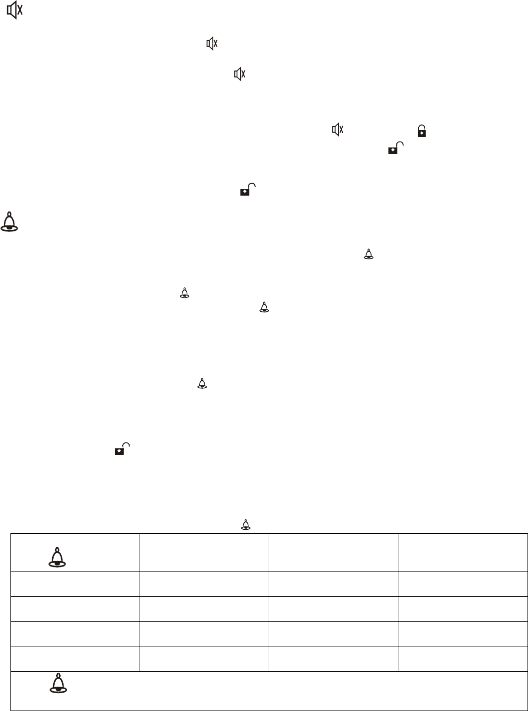
Turning ACC, IGN1, IGN2 ON/OFF and Starting the
Engine:
When in Disarm
mode
and
the RFID key FOB
is
in detection range
.
To
Turn ACC ON/OFF
Pre
ss
“PUSH START STOP”
button once then release, ACC will turn ON; press
“PUSH START STOP”
button once again then release, ACC will turn OFF.
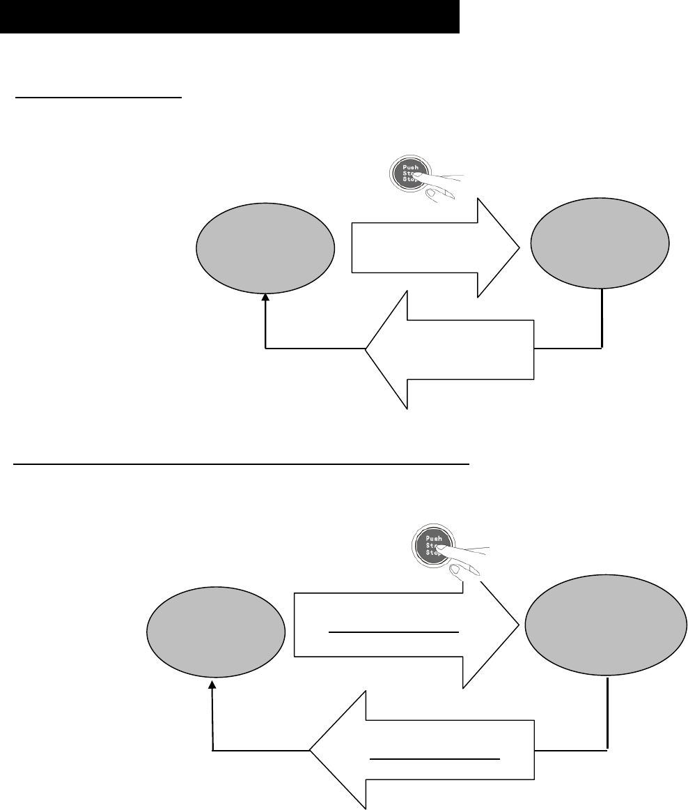
To
Turn ACC, IGN
1
and
IGN
2 ON/OFF with no engine start.
Press
“PUSH START STOP”
bu
tton and hold for 1.5 sec. without pressing the brake/clutch peddle, ACC,
IGN 1 and IGN2 will turn ON and the engine will not start. To turn ACC, IGN1 and IGN2 OFF, press
and hold for 1.
5 sec.
“
PUSH START STOP”
button
,
or
w
hen the RFID key FOB is taken out of range,
ACC,
IGN1 and IGN2 will turn OFF automatically
.
OFF
ACC
, Ign1
& IGN2
ON
Press button
for 1.5 Sec
No brake or clutch
Press button
for 1.5 Sec
No brake or clutch
.
OFF
ACC
ON
Press button once
then release it
Press button once
then release.
1.3
“PUSH START STOP” BUTTON OPERATION
© Copyright
Gallo Technologies
. All Right Reserved
-
6
-
10810
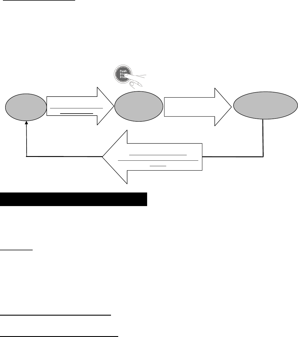
To Start / Stop Engine.
To Start Engine:
While
pressing the brake/clutch peddle
,
Press
“PUSH START STOP”
button and hold
until the engine starts.
IGN 1 will turn ON
,
the starter wi
ll engage
and the engine will start.
After the
engine has started, release the
“
PUSH START STOP”
button
,
ACC, IGN1 and IGN2
will turn ON.
To Stop Engine:
press “
PUSH START STOP”
button
for 1.5 sec. IGN 1 and IGN 2 will turn OFF and the
engine will stop.
ACC will remain ON until (a.) the
“
PUSH START STOP”
button
is pressed one time, or,
(b.) the key FOB is moved out side the vehicle and is out of range.
GTStarter
-
2
has numerous user configurable features that can be
enabled or modified according to user’s
preferences. This section explains each of the user configurable functions. See
Sec.
1.5 “
Programming Function
Set
-
Up Options”
for details on how to modify configurable features.
Valet Mode
: In
DISARM mode
,
Press
ing
valet switch
for
over 5 seconds
will activate valet mode. Siren will chirp 2
times and the green LED will stay ON.
To deactivate valet mode (normal status)
,
press the valet switch for over 5 seconds. The siren will chirp one time
and the green LED
will flash slowly.
In Valet mode all alarm function will be disabled.
The key FOB buttons can
lock and unlock doors
, but not the trunk
.
“Push Start Stop”
button functions will continue as in Normal status. If the
key FOB is in range
,
the vehicle can be
started with the
“Pu
sh Start Stop”
button or the ignition key,
if
an ignition key switch is
also
used.
Transmitter (Key FOB) Code learning:
The Key FOBs must be learned by the
Control M
odule before they will
function.
Automatic Door Lock / Unlock Function:
Enabled:
W
hen the key FOB i
s within range, the doors unlock automatically and the system enters Disarm mode,
the lights flash twice ,
siren
chirps twice (by short tone) (if Silent arm/disarm function is set to OFF). The
“
Push
Start Stop”
is activated when the door is opened, and th
e green LED flashes.
W
hen the key FOB is out of range, the doors lock automatically and the system enters the Arm mode. The lamps
flash once,
siren
chirps once by short tone, (if Silent arm/disarm function is set to OFF). The
“
Push
Start Stop”
b
utton is disable
d and the blue LED flashes.
Disabled:
When the key FOB is within range,
and the system is in disarm
mode
, the lights will flash 2 times. The
“
Push
Start Stop”
b
utton
is activated when the door is opened. The green LED will flash slowly. The siren will no
t
chirp.
OFF
Ign1 ON
Starter
Engaged
Press
and hold
button
While pressing foot brake
or clutch peddle
Press button for 1.5 Sec
No brake or clutch
required
IGN1, IGN2 will turn OFF & ACC will
stay ON
.
Release after engine start
ING2 & ACC
will turn ON
En
gine running
Ign1, IGN2 & ACC
ON
1.
4
GTStarter
-
2
FUNCTION OPTIONS
© Copyright
Gallo Technologies
. All Right Reserved
-
7
-
10810
When the key FOB is out of range, the doors will
not lock
and the system will stay in Disarm mode. The lamps will
flash once when the door is closed and the siren will not sound. ACC will turn OFF and the
“
Push
Start Stop”
b
utton will be disable
d.
NOTE: When the key FOB is out of range and
“A
uto door lock / unlock” function is disabled,
t
he doors can be
locked/unlocked and the system armed/disarmed by pressing either key FOB button
(arm button) or
(disarm
button
)
.
Automatic / Manual Transmission
: Determine if the vehicle
has
an automatic or manual transmission. Set the
“Automatic / Manual Transmission” function accordingly.
S
ee
Figure 1.
Option 4
S
ile
nt
A
rm/Disarm
:
Enabled
:
Siren does not chirp when locking / unlocking the doors.
Disabled:
Siren chirps when locking / unlocking the doors.
Foot
-
Brake lock/unlock
:
Enabled:
15 seconds after starting the engine the doors will automatically lock when the
foot brake is pressed.
Doors will automatically unlock when the engine is turned OFF.
Disabled:
After starting the engine the doors will not automatically lock.
Auto
Rea
rm:
E
nabled:
T
he system will automatically rearm and relock itself within 30 secon
ds after the system is
disarmed
by
pressing
, if the door is not opened
.
Disabled
:
The system will not automatically rearm and
relock itself
after the system is
disarmed
by pressing
, if
the door is not opened
.
Electrical Siren/ Horn:
Electrical Siren:
Set if the 6 tone siren (included) is used.
Horn:
Set if the vehicle’s horn is to be used instead of the 6 tone siren. An additional relay may be required. The
control modu
le siren output is a low current output and must go through a relay to operate a vehicle’s horn.
Central
Locking Time:
When pressing
or
the electrical pulse sent to the door locking/unlocki
ng mechanism
can be set at either 0.
5
seconds or 4 seconds. Most cars will function properly when this option is set to the factory
default of 0.
5
seconds.
Door Open Light Flashing:
Enabled:
The parking lights will flash 2 times when a door is opened.
Di
sabled (default):
The parking lights will not flash when a door is opened.
RFID S
can time
:
Short
(
default):
Sets the interval between the RFID transmitter scans to a shorter period of time.
Shorter b
attery life
& shorter
detection
time.
Long:
Sets the interval between the RFID transmitter scans to a l
onger period of time.
Longer
b
attery life &
longer
detection
time.
Note: If there is no RFID detection activity for 72 hours or more, the RFID scanner will turn OFF. Pressing
any button on the Key FOB will reactivate the RFID scanner.
Anti
-
hijack:
Enabled (default):
Turns ON
Anti
-
Hijack
Function
.
OFF
:
Turns OFF
Anti
-
Hijack
F
unction
.
© Copyright
Gallo Technologies
. All Right Reserved
-
8
-
10810
A.
C
ode learning (code learning mode, for the new transmitter
s
)
1.
System must be in
Disarm mode
(green LED flashing).
2.
Press
the
valet switch 3 times,
then
hold the valet switch for over 5 seconds, it will enter the code lea
rning mode.
The g
reen LED will light up and
the parking lights
will
flash
2 times
.
3.
Immediately (within 5 seconds) p
ress
the
button
on the new key FBO that needs to be code learned.
When
the parking lights flash 4 times,
co
de learning
was successful. Repeat this process if an additional Key FOB
needs to be code learned.
B.
Function Programming
:
1.
System must be in
Disarm mode
(green LED flashing).
2.
Press valet switch 5 times,
then
hold the valet switch for over 5 seconds,
p
arking
lights will flash 2 times
.
3.
According to the
“Function Option Chart” below
, you can set up the required function by pressing
the
Valet
Switch
the
number of times
indicated in Table 1
.
4.
Immediately after pressing the valet switch the number of ti
me indicated press the
button on the key FOB.
If
the
parking lights
flash 3 times,
the default setting for that function has been set. If the parking lights flash 1 time,
the alternate setting has been set.
Note:
After ent
ering
the “Function Programming” mode
,
the
button must be pressed on the key FOB within 5
seconds. If not, the system will exit the “Function Programming” mode and the parking lights will flash 4 times.
Repeat steps 1 thru
4 for each additional programming function.
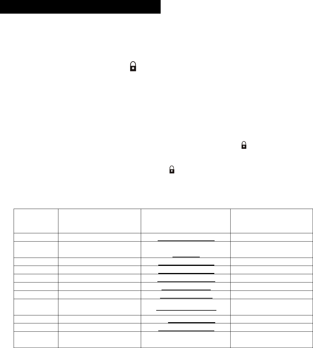
Table 1: FUNCTION OPTION CHART
P
ress Valet
Switch
# of Times
Programmable
function
Function
Default
Lights flash 3 times
Function
Alternate
Light flash 1 time
1
A
uto door lock/unlock
Enabled (Default)
Aut
o lock/unlock OFF
2
Automatic/Manual
transmission
Automatic transmission
(
d
efault)
Manual transmission
3
S
ilent arm/Disarm
Enabled
(
d
efault)
Disabled
4
Foot
-
Brake lock/unlock
Enabled (
d
efault)
Disable
5
Auto
Rea
rm
Disabled
(
d
efault)
Enabled
6
Electrical Siren/ Horn
Electrical siren
Horn
7
Central lock
Time
0.5sec. (default)
4 sec.
8
Door Open Light
Flashing
Disabled
(default
)
Enabled
9
RFID
scan time
Short
(default)
Long
1
0
Anti
-
hi jack
Enabled (
d
efault)
OFF
1
1
Reset to
Factory
Default
s
1.
5
PROGRAMMING FUNCTION SET UP

© Copyright
Gallo Technologies
. All Right Reserved
-
9
-
10810
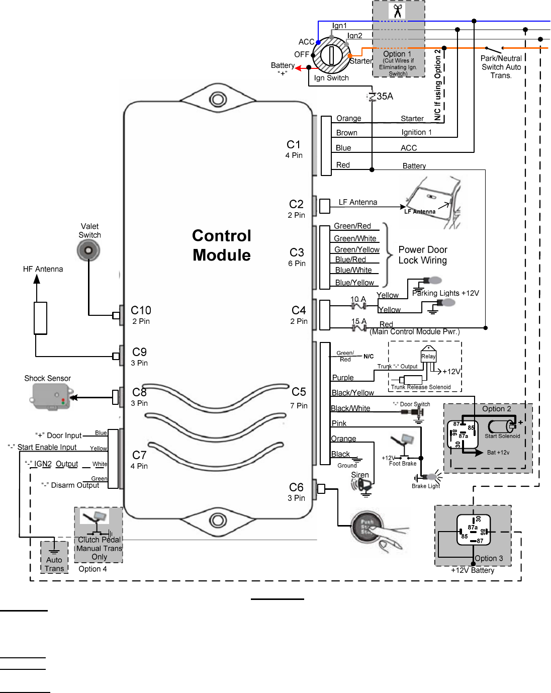
SEE Figure
1
F
or Location and Identification of GTStarter
-
2 Control Module Connectors.
4 Pin Wire Harness (
Battery, Ign1, Starter, ACC
)
IMPORTANT:
Read
Figure 1
.
Option 1
before cutting
any ignition switch wires
.
C1: RED
–
Battery
Supply Power
From Ignition Switch
.
The RED wire is used to power
the GTStarter
-
2
starting circuitry
, Ign1, and ACC
.
Before connecting this wire you
must first find the
BAT
wire com
ing from the ignition switch. The
BAT
wire is used to
supply
+
12v
battery power
to
the
entire vehicle.
Solder connect the C1 RED wire
(w/ 35amp fuse)
to the
BAT
wire coming from the Ignition switch.
At the same time that you connect the C1: RED wire, also
solder connect the PINK
fused
wire from connector
C
4
.
C1: ORANGE
–
Start
er
Output.
Before connecting this wire you must first find the
START
wire coming from the ignition switch. The
START
wire is
used to send +12v through the Park/Neutral safety switch
(automatic transmission) to the starter solenoid. Insure
that you DO NOT by
-
pass the Park / Neutral switch; otherwise the engine could be started while in Drive or
Reverse.
Manual transmission vehicle typically do not have a Park/Neutral switch. S
older co
nnect the C1:
ORANGE wire to
the
START
wire
.
C1: BLUE
–
ACC Power Output
The C1: BLUE wire directly sends a +12 v signal from the
Control M
odule to
power
the
Accessory (ACC)
circuits.
The ACC circuit has power applied to it only when the ignition key or “Pus
h Start Stop” button is in the ACC position
or when the key / “Push Start Stop” button is in the ON position. No power is applied during the engine starting
cycle.
Solder connect the C1: BLUE wire to the
ACC
wire
coming from the ignition switch
.
C1:
B
ROWN
–
IGN 1 Power Output
The
IGN 1
wire is used to send +12v to the ignition system and engine computer when the ignition
key
or “Push
Start Stop” button
is in the
ON
and
START
position. Solder connect the C1
BROWN
wire to the
IGN 1
(ignition/computer) w
ire coming from the Ignition switch.
2
Pin
Low Frequency (LF) Antenna
Wire Harness
.
The LF antenna is used for the RFID circuitry. The antenna should not be placed directly on any metal surface. The
best location is usually on the windshield glass alon
g side the driver’s side
“
A
”
pillar. To optimize the RFID range
other locations on a glass surface can be tested. Before
permanently
attaching the antenna, experiment with
different locations that
may further optimize the key FOB range.
Plug in the 2 pin LF antenna into the
Control M
odule
indicated in
Figure 1
.
Installing Connector C1:
1.
6
INSTALLATION INSTRUCTIONS
Installing Connector C2:
© Copyright
Gallo Technologies
. All Right Reserved
-
10
-
10810
Figure 1
Option 1
–
The user has the option of keeping the original ignition switch or completely removing it.
If the ignition is kept
operational, t
he vehicle can then be started w
ith either the “Push Start/Stop” button or the ignition key. If eliminating the Ignition
Switch, cut all wires as shown. If the Ign
ition
switch is not being eliminated do not cut the wires, the engine can then be started
with either the ignition switch OR
the “Push Start Stop” button.
Option 2
-
Use this wiring when the vehicle’s starter solenoid requires more than 10 Amps. i.e. Heavy duty trucks.
Option 3
-
Use this wiring to energize (Max 150 MA) an optional relay when your vehicle uses both an Ign 1 & Ig
n 2 circuits
during Starting & Run. The relay AMP rating will need to be high enough to carry the load for your vehicle.
Option 4
–
For Automatic transmission connect “Start Enable Input” (yellow) wire to chassis ground “
-
“
For Manual Transmission connect
“Start Enable Input” (yellow) wire to
the clutch peddle switch that grounds “
-
“
when the peddle is depressed.
© Copyright
Gallo Technologies
. All Right Reserved
-
11
-
10810
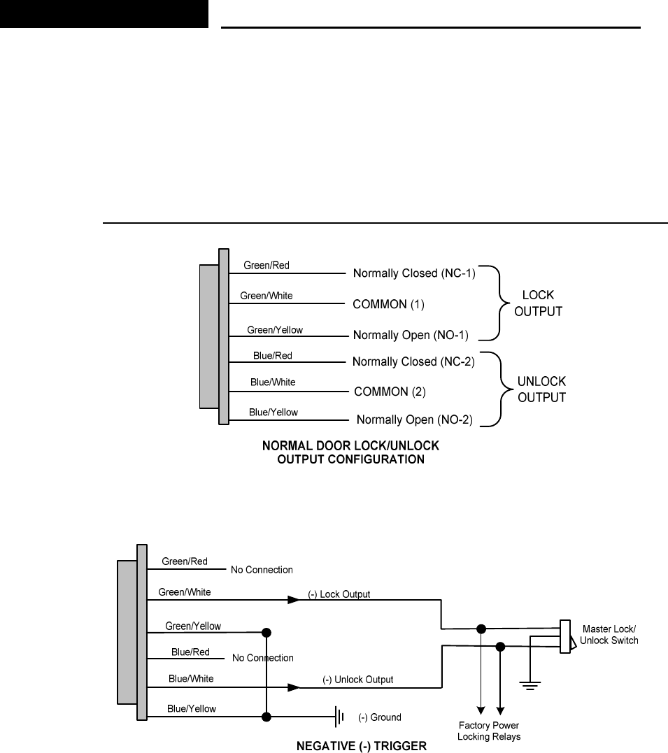
6 Pin Wire Harness (Door Lock/Unlock Circuit)
Determine the Door Locking/Unlocking circuitry that your vehicle is equipped with. Fig.
2
shows the door lock/unlock
output relay configuration of
the Control Module.
The majority of vehicles come equipped with
either
Neg (
-
)
Fig.
3
or
Pos
. (
+) Fig.
4
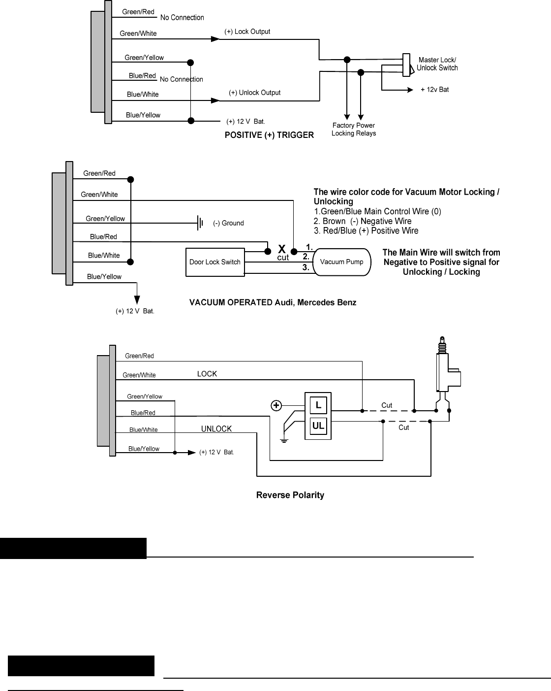
Trigger circuits. Find the location of the appropriate circuitry for your vehicle (Make, Mod
el, Year
Diagrams can be found on our web site at www.GalloTech.com) If the Trigger wire is 0v when the Lock/unlock
switch is depressed then you have a Neg. (
-
) trigger
(Fig.
3
). If the trigger wire is +12v when depressing the
Lock/unlock switch then you
have a Pos
. (
+) Trigger (Fig
4
). For Pre
-
’95 Audi or Mercedes Benz vacuum motor
operation use Fig.
5
. For Reverse Polarity applications, were the
lock and unlock wires rest at Negative Ground,
use
Fig.
6
.
C
3
: 6 PIN WIRE HARNESS DIAGRAMS: Door Locking/Unl
ocking Circuits
Figure
2
Figure
3
Installing Connector C
3
:
© Copyright
Gallo Technologies
. All Right Reserved
-
12
-
10810
Figure
4
Figure
5
Figure
6
2 Pin Wire
Harness (
Control Module Pow
er, Parking lights
)
C
4
: RED
15 Amp
fused wire
–
+ 12v Constant Battery Input (
Control
Module Supply Power)
. This connection
should
have constant
+12v available (
BAT
terminal on ignition switch or equivalent). Solder connect the RED wire.
C
4
: YELLOW
–
Parking Light +12v
output
10
Amps
fused
.
Solder connect
one of the YELLOW wires to the
vehicle’s parking light relay. If parking lights require more than
5
amps use an external
30
Amp relay.
7 Pin Wire Harness
(
Trunk Release
, Door
Trigger Circuit
,
Foot Brake
Switch, Siren and System Ground
)
.
C
5
:
GREEN/RED
–
No Connection.
Installing Connector C
4
:
Installing C
onnector C
5
:

© Copyright
Gallo Technologies
. All Right Reserved
-
13
-
10810
C
5
: P
URPLE
–
Trunk Release Output Neg. (
-
)
.
Connect the PURPLE wire to the trunk release Neg. (
-
) trigger wire
on the vehicle’s trunk release relay. In the eve
nt that a trunk release is to be added to the vehicle,
an
additional relay
and trunk release solenoid will be required.
C5:BLACK/YELLOW
–
Optional high current starter solenoid relay
. See
Figure 1
.
“Option 2”
above for
connection.
C
5
: BLACK/WHITE
–
N
eg. (
-
) Door Trigger switch Input.
Connect the
BLACK/WHITE wire
to the Neg. (
-
) Door
Trigger switch. If
the
vehicle has “+” Pos Door Trigger input use
the BLUE wire from connector
C7
.
C5: PINK
-
(
+12v
)
Foot Brake Switch Input Used for door lock
and Star
ter enable
input
.
Connect to Foot brake
switch terminal that has +12v only when foot brake is depressed.
C5:
ORANGE:
-
Siren +12v Output.
Connect to the RED
Siren wire
. Connect the second siren input (BLACK wire)
to a good chassis ground.
C
5
: BLACK
–
Ne
g. (
-
) Ground Connection
.
Connect the BLACK wire to a good chassis ground in a convenient
location.
3 PIN Wire Harness
(
“
Push Start Stop
”
Button)
The
“PUSH START STOP”
button can be surface mounted in a
convenient location on the dash or can be mounted
using the supplied adjustable bracket for mounting under the dash or on the console. The high strength double stick
adhesive disk is to be used on the back side of the switch with both mounting methods. Mak
e certain that the back
of the button and the mounting surface is thoroughly cleaned with
isopropyl alcohol
to remove any dirt, grease or
vinyl dressing materials.
DO NOT use acetone, MEK, lacquer thinner or any other harsh chemicals as they will
destroy p
aint, vinyl and plastic
. The adhesive will not come loose or degrade as long as the surface has been
cleaned thoroughly. Attach the adhesive disk to the back of the button first.
If you choose to mount the button on the dash with the wire hidden behind the
button then drill a 3/8” dia. hole in a
location where the small wire and connector can be fed through the dash. Rout the
“PUSH START STOP”
button
wire to the module. Connect the White 3 terminal connector to the module. The connector is indexed so that it can
only be installed in one direction.
4 Pin Wire Harness ( Start enable & Disarm Output)
C7: BLUE
–
Pos. (+) Door Switch Input.
Connect the
BLUE
wire
to the
Pos.
(
+
) Door Trigger switch. If
the
vehicle
has “
-
”
Neg.
Door Trigger input use
the
BLACK/WHITE
wire from connector
C5
.
C7: YELLOW
–
Start Enable Input.
For
A
utomatic
T
ransmission
:
Connect the YELLOW wire to a good chassis ground (
-
).
For Manual Transmission:
Connect the YELLOW wire to a clutc
h peddle switch that has a neg. (
-
) output when the
clutch peddle is depressed.
C7: GREEN
–
Neg (
-
) Disarm Output to enable security bypass devices.
Connect the GREEN wire to the Neg (
-
)
input of a security bypass device. These devices are used in the eve
nt that the vehicle has an OEM security system
that prevents starting the vehicle without the security key. The proper security by
-
pass module for the specific
vehicle can be found at
www.gallotech.com/support.php
.
Follow the instruction that came with the
by
-
pass
modu
le.
-
3 Pin Shock Sensor Wire Harness
C8: Shock Sensor
–
The shock sensor should be mounted on a rigid member of the vehicle. Typically it is best
attached to the steering column. The shock sensor should never be mounted on the outside of
the vehicle where it is
not protected from exposure to moisture.
Connect the 3 Pin connector to both the shock sensor and the Control
Module as shown in
Figure 1
.
Installing Connector C
6
:
Installing Connector C
7
:
Installing Connector C
8
:

© Copyright
Gallo Technologies
. All Right Reserved
-
14
-
10810
-
3 Pin HF Antenna
wire harness
C
9
:
-
HF Antenna
–
The HF antenna is used for the high frequency receiver that operates the remote access
functions such as remote door locking, car locating, and anti hi
-
jack. The location is not all that critical because of
the type of antenna that we use
, therefore the antenna can be placed anywhere under the dash and out of sight.
Caution should be taken as the antenna wip is metal and the installer should insure that the wip will not interfere /
short out any under
-
dash wiring. Connect the 3 Pin connec
tor to the
Control Module
as shown in
Figure 1
.
-
2 Pin Valet Switch wire harness
C10: Valet Switch
–
The Valet Switch should be mounted under the dash or in the glove box so that it can be
accessed
from time to time to change or modify the programmable functions of GTStarter 2. Connect the 2 pin
connector to the Control Module as shown in
Figure 1.
1.
Recheck all electrical connections to be certain they are connected in the proper locations and
check that
all connections are wrapped with a good quality electrical tape or shrink tubing.
2.
Connect all
10
module connectors to the
Control M
odule. The
Control M
odule
should be secured under
the dash using cable ties or equivalent.
3.
If the vehicle is equipped with a locking steering column, it must be
permanently
disabled before
attempting to d
rive the vehicle.
4.
Reconnect the battery and thoro
ughly test all starting functions.
Code learn the key FOBs first.
None of the Control Module functions
will
operate
until the key
FOBs have been taught to the
Control M
odule.
See Sec. 1.5 for code learning i
nstructions.
Make certain that the vehicle can not be started while it is in any gear except Neutral and/or
Park (automatic transmission).
Test the starting function
:
Automatic transmission:
Press and hold the “
Push Start Stop
” button
without pressing the brake peddle,
making certain that the vehicle will not start. The engine should only start when the brake is pressed and
the vehicle is in Park or Neutral.
If the engine starts without the brake peddle being depressed, then the
wiring connections to the Control Module and the connections to the Park Neutral switch must be
rechecked per Figure 1.
Manual Transmiss
ion:
Press and hold the “
Push Start Stop
” button without pressing the clutch peddle,
making certain that the vehicle will not start. The engine should only start when the clutch peddle is
pressed. If the engine starts without the clutch peddle being depres
sed, then the wiring connections to the
Control Module must be rechecked per Figure 1.
5.
Program the module to the functions that you desire following Sec. 1.
5
“Program Function Set Up”
and
Table 1
“
Function Option Chart”
.
ENGINE CRANKS BUT WILL NOT START:
1.
Check Ignition switch wiring.
See Sec. 1.6
“Installing Connecto
r C1
.
Some vehicles require 2 separate
ignition wires
Ign 1
and
Ign 2
for the vehicle’s ignition system to function properly.
If the vehicle requires both
Ign 1 & Ign 2 then follow the instructions in
Figure 1. Option 3.
2.
If the vehicle has a secur
ity key, check that the security by
-
pass module is installed properly.
See connector
C7: GREEN wire installation in
structions on page
13.
1.6 FINAL INSTALLATION
1.7 TROUBLESHOOTING
Installing Connector C
9
:
Installing Connector C
10
:

© Copyright
Gallo Technologies
. All Right Reserved
-
15
-
10810
ENGINE STARTS IN DRIVE OR REVERSE
GEAR (AUTOMATIC TRANSMISSION).
Check the location of
C1:
ORANGE (
Starter
output)
wire.
It
MUST be connected to the vehicles start
er
wire close to
the ignition switch, making certain that the Park/Neutral lockout is not bypassed.
A
lso check
Table 1
for correct
transmission selection
.
ENGINE STARTS
WHEN THE CLUT
CH IS NOT PRESSED (MANUAL
TRANSMISSION).
Check the
connection
of
C7: “Start Enable
Input” (Yellow) wire. It must be connected to a clutch switch that grounds
Neg. (
-
) when the clutch is pressed. If the clutch peddle switch is Pos. (+) when the clutch is pr
essed then a relay is
required to reverse the input to Neg. (
-
).
A
lso check
Table 1
for correct
transmission selection
.
AN ACCESSORY (RADIO, HEATER FAN, ETC.) DOES NOT TURN OFF DURING ENGINE CRANKING AND/OR
TURN BACK ON AFTER CRANKING:
a.)
Check the connections of C1: wire harness for the correct connection points
. See
Figure 1
.
There are
usually only two positions on the ignition switch which disconnect power to the accessories during engine
cranking.
ACC and/or IGN 2. In some vehicles IGN 2 is used for either accessories like the heater fan, or is
some times use
d as an additional ignition system wire.
Check the specific wiring diagrams for your Make,
Model, and Year vehicle.
These can be found at
www.gallotech.com/support.php
.
b.)
Check
all fuses connected to the Control
Module wire harnesses.
If
any are
blown then there must be a short
in the system. Check all wiring thoroughly.
DOORS LOCK/UNLOCK WHEN THEY SHOULD UNLOCK/LOCK:
Connector C
3
: 6 Pin Wire Harness wires have been incorrectly connected to the vehicles Master Lo
ck switch.
Revers
ing
the
Lock and unlock wires
at the C3 connector of the Control Module
will correct the problem.
INSTALLATION NOTES