GameTech 99-00002-0000 900 MHz transmitter User Manual RF
Gametech International 900 MHz transmitter RF
UserManual.wiki
>
GameTech
>
99-00002-0000 User Manual
>
final manual
Contents
1.
draft manual1
2.
draft manual2
3.
final manual
final manual
Navigation menu
Upload a User Manual
Namespaces
Wiki Guide
HTML
PDF
Info
Views
User Manual
Discussion / Help
Navigation


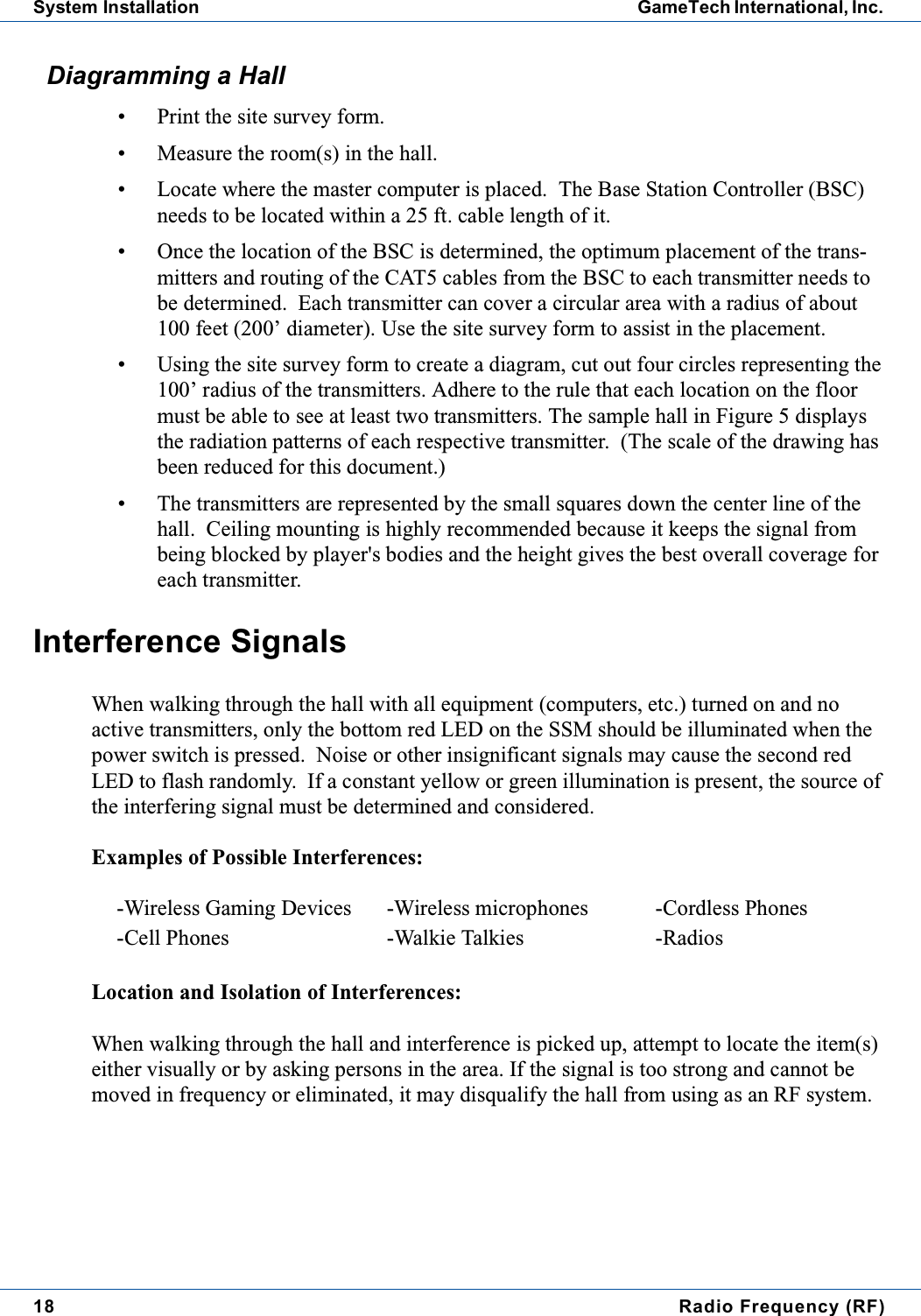
![Radio Frequency (RF) 19GameTech International, Inc. System InstallationCoverage• Position the standalone battery-powered transmitters in locations determined by thepaper survey.• The SSM is then used to determine the adequacy of coverage of the transmitterplacement.• With the system active at least one green LED should illuminate in all locationswithin the circle defined by the paper survey. Remember with one transmitteronly, you may see the "dead spots" from location to location as you movethrough the area. This is normal. The SSM's receiver is calibrated to respondlike those in the TED®and TED2C™.• One green LED illuminated is sufficient signal for essentially error free datatransmission. When the entire system is installed it's expected for the top greenLEDs to blink during normal system operation. Each transmitter is turned onsequentially by the BSC. No two transmitters are ever on at the same time.Consequently, the signal strength indicated by the green LEDs will vary caus-ing the top LEDs to blink on and off at the scan rate of the system. This phe-nomenon is caused by the SSM picking up transmitters close by (large signal)and those farther away (small signal).• If the signal strength, as indicated by the SSM, is adequate throughout the hall, thehall can be considered a good candidate for the RF system.MASTER.INI SettingsMake the following changes to the [GENERAL] section of the MASTER.INI:(\TXT directory)RFENABLED=0.........................0=Off or 1, 2, 3 or 4 for appropriate com port.CHH.INI SettingsMake the following changes to the [GENERAL] section of the CHH.INI: (\CHH directory)USE_RF=1 .................................................... This setting should always be one.](https://usermanual.wiki/GameTech/99-00002-0000.final-manual/User-Guide-282775-Page-27.png)