Garland 200 Users Manual
200 to the manual 241424dc-a468-4d4b-a8bb-ee8bcdc00370
2015-02-09
: Garland Garland-200-Users-Manual-559123 garland-200-users-manual-559123 garland pdf
Open the PDF directly: View PDF ![]() .
.
Page Count: 124 [warning: Documents this large are best viewed by clicking the View PDF Link!]
GARLAND COMMERCIAL INDUSTRIES
185 East South Street
Freeland, Pennsylvania 18224
Phone: (570) 636-1000
Fax: (570) 636-3903
GARLAND COMMERCIAL RANGES, LTD.
1177 Kamato Road, Mississauga, Ontario L4W 1X4
CANADA
Phone: 905-624-0260
Fax: 905-624-5669
Enodis UK LTD.
Swalloweld Way, Hayes, Middlesex UB3 1DQ ENGLAND
Telephone: 081-561-0433
Fax: 081-848-0041
Part # MCOSM06 Rev 1(11/03/08) © 2006 Garland Commercial Industries, Inc.
Service Manual For MCO GS/GD
Full Size "Gas" Convection Ovens
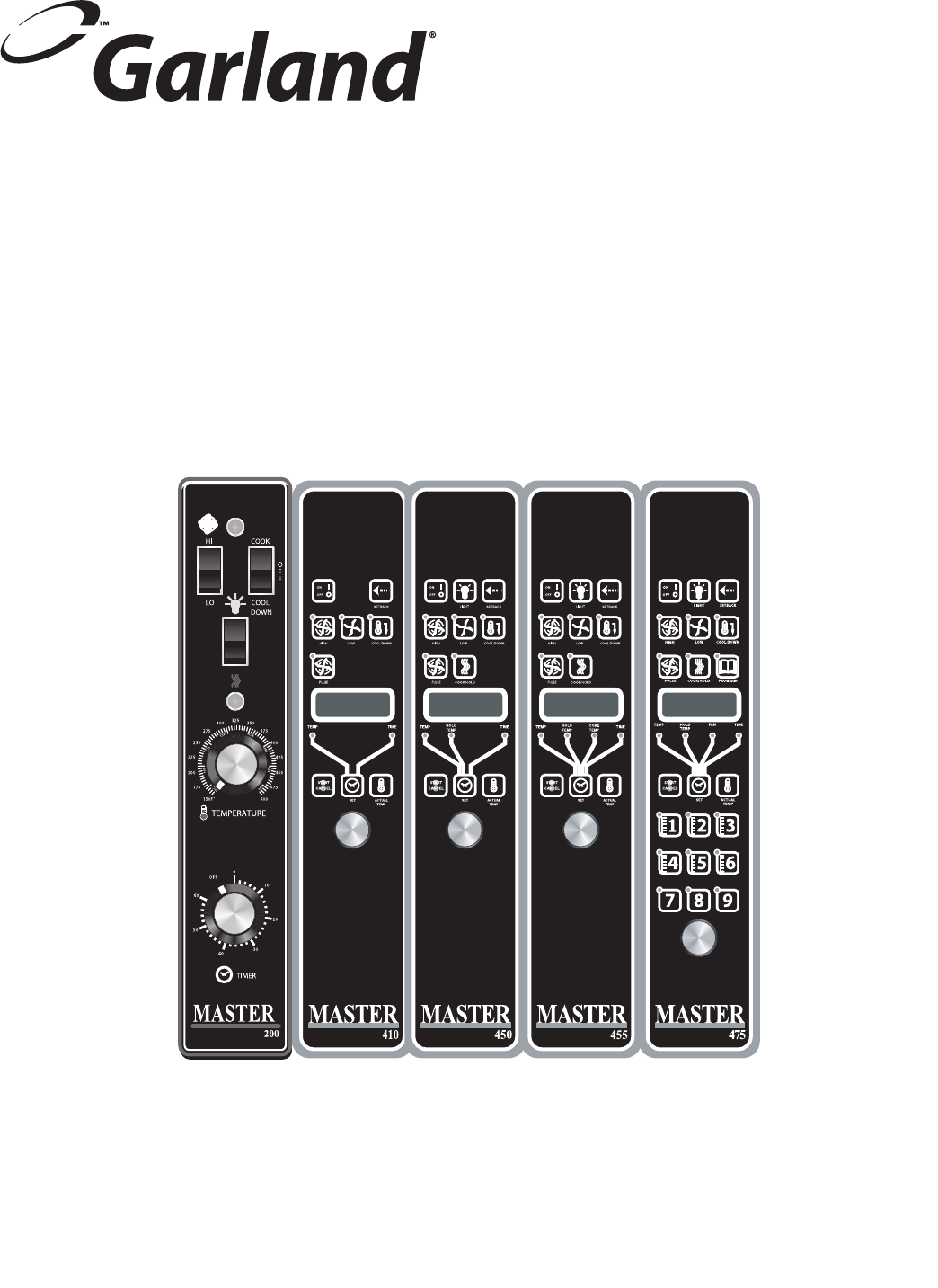
With 200, 410, 450, 455, 470, 475 Series
Controllers

Page 2 Part # MCOSM06 Rev 1 (11/03/08)

Part # MCOSM06 Rev 1 (11/03/08) Page 3
TABLE OF CONTENTS
Section One Operation Manual .................................................5
Contents....................................................................................6
Dimensions & Specications .................................................................7
Installation..................................................................................8
Operation .................................................................................12
Performance Recommendations ............................................................21
Cooking Guide .............................................................................22
Cook And Hold.............................................................................23
Problems / Solutions .......................................................................24
Cleaning & Maintenance....................................................................25
Motor Care.................................................................................26
Section Two Electronic Pilot & Main Burner .....................................27
Ignition Sequence..........................................................................28
Trouble Shooting Table.....................................................................29
Service ....................................................................................30
G77x Intermittent Pilot Controls.............................................................32
G76x Direct Spark Ignition Controls .........................................................35
Section Three Temperature Calibration.........................................39
General Calibration.........................................................................40
200 & 300 Series Controllers Calibration .....................................................41
Section Four Convection Oven Components ....................................43
Doors......................................................................................44
Door Latch Mechanism .....................................................................47
Motor .....................................................................................48
Door Microswitch ..........................................................................50
Probes.....................................................................................51
Key Pad Test ...............................................................................52
Mco Convection Oven Gas Valve ............................................................53
Relay Boards . . . . . . . . . . . . . . . . . . . . . . . . . . . . . . . . . . . . . . . . . . . . . . . . . . . . . . . . . . . . . . . . . . . . . . . . . . . . . . . 54
Controls ...................................................................................57
Section Five Trouble Shooting .................................................59
Controller Operational Tests ................................................................60
Controller Fault Finding ....................................................................61
Additional Notes ...........................................................................63
General Trouble Shooting Guide ............................................................64
Section Six Service Bulletins ...................................................67
Section Seven Wiring Diagrams ...............................................101

Page 4 Part # MCOSM06 Rev 1 (11/03/08)

Part # MCOSM06 Rev 1 (11/03/08) Page 5
Section One
Operation
Manual

Page 6 Part # MCOSM06 Rev 1 (11/03/08)
CONGRATULATIONS! You have just purchased the nest commercial cooking equipment available anywhere.
Like any other ne, precision built appliance, it should be given regular care and maintenance. Periodic inspections by your
dealer or a qualied service agency is recommended. When corresponding with the factory or your local authorized factory
service center regarding service problems or replacement parts, be sure to refer to the particular unit by the correct model
number (including the prex and sux letters and numbers) and the warranty serial number. The rating plate axed to the
unit contains this information.
CONTENTS
DIMENSIONS & SPECIFICATIONS ...............7
INSTALLATION ................................8
Installation Notes: .....................................8
Installation Of Ovens Equipped With Casters ...........8
Installation Of Double Deck Models . . . . . . . . . . . . . . . . . . . 8
Gas Connection .......................................9
Electrical Connection .................................9
Ventilation & Air Supply ...............................9
Testing & Lighting Instructions . . . . . . . . . . . . . . . . . . . . . . . 11
OPERATION..................................12
Master 200 Mechanical Control with Timer ............12
In O Mode: ..................................... 12
Start Up:......................................... 12
Fan Speed:....................................... 12
Lights: ........................................... 12
Cool Down: ...................................... 12
Temperature: .................................... 12
Timer: ........................................... 12
MASTER 300 Solid State Control ......................13
In O Mode: ..................................... 13
On Start Up: ..................................... 13
Controller Keys .................................. 13
MASTER 410,450, 455 CONTROLS .....................14
In O Mode: ..................................... 14
On Start Up: ..................................... 14
Operating the Controls........................... 15
Cook-N-Hold Operation.......................... 15
Core Probe Operation............................ 16
CHANGING FACTORY SETBACK PROGRAM ........ 16
MASTER 470/475 CONTROLS ..........................17
Manual cooking: ................................. 17
Manual cooking using Cook-N-Hold: ............. 17
Programming Product Keys (Master 475): ......... 17
Programming Product Keys (Master 470): ......... 19
Cooking Using The Product Keys(475 and r 470): .. 19
Verifying hold time (475 and 470): ................ 19
Cooking with the Shelf Timer (475 and 470): ......20
PERFORMANCE RECOMMENDATIONS .........21
COOKING GUIDE .............................22
COOK AND HOLD ............................23
PROBLEMS / SOLUTIONS .....................24
CLEANING & MAINTENANCE ..................25
Break-In Period ......................................25
Exterior Cleaning ....................................25
Interior Cleaning .....................................25
Fan Area Maintenance. . . . . . . . . . . . . . . . . . . . . . . . . . . . . . . .25
MOTOR CARE ................................26
Part # MCOSM06 Rev 1 (11/03/08) Page 7
Gas Input ratings shown here are for installations up to 2,000-ft. (610m) above sea level. Specify altitudes over 2,000 ft.
Commercial cooking equipment requires an adequate ventilation system. For additional information, refer to the National Fire
Protection Association’s standard NFPA96, "Vapor Removal from Cooking Equipment." (NOTE: For North America only)
Please specify gas type when ordering.
7-3/4"
[197mm]
38-1/4"
[972mm]
3/4"
[19mm]
17-3/4"
[451mm]
TOP VIEW
2"
[51mm]
FLUE: 2-3/8" x 5"
[60mm x 127mm]
3/4" N.PT.
GAS INLET
11-1/2"
[292mm]
38"
[965mm]
32-1/8"
[816mm]
25-3/8"
[645mm]
SINGLE DECK
FR ONT VIEW
1-1/4"
[32mm]
34"
[864mm]
54-9/16"
[1386mm]
3/4" REAR
GAS INLET
32-1/8"
[816mm]
32-1/8"
[816mm]
6-1/4"
[159mm]
14-3/4"
[375mm]
32-1/8"
[816mm]
35-7/16”
[900mm]
32-1/8"
[816mm]
1-1/4"
[32mm]
DOUBLE DECK
FR ONT VIEW
D
H
H
1" REAR
GAS INLET
Single-Deck
Models
Int. Dimensions :In (mm) Ext. Dimensions: In (mm) Ship Wt Ship Dim.
W H D W H * D Lbs/kg Cubic Ft.
Standard Depth 29 (736) 24 (610) 24 (610) 38 (965) 57-1/2 (1461) 41-1/4(1048) 600/273 64
Deep Depth 29 (736) 24 (610) 28 (711) 38 (965) 57-1/2 (1461) 44-1/2(1130) 600/273 64
Double-Deck
Models
Int. Dimensions: In (mm) Ext. Dimensions: In (mm) Ship Wt. Ship Dim.
W H D W H * D 2@Lbs/kg Cubic Ft.
Standard Depth 29 (736) 24 (610) 24 (610) 38 (965) 70-1/2 (1791) 41-1/4(1048) 1150/523 128
Deep Depth 29 (736) 24 (610) 28 (711) 38 (965) 70-1/2 (1791) 44-1/2(1130) 1150/523 128
*Height with or without standard casters. Height with low prole casters (double deck) is 68-1/2" (1740mm).
Models Input Ratings, Nat & Pro Electrical Specications
BTU/hr kW Equiv. Gas Inlet 120V/1Ph. 240V/1Ph.
Single Deck 60,000 17. 6 (1 )@ 3/4" NPT (1)@9.4A (1)@ 5.2A
Double Deck 120,000 35.2 (1 )@1" NPT (2)@9.4A (2)@ 5.2A
Installation Notes:
Combustible Wall Clearances:
Sides: 1" (25mm)
Back: 3" (76mm)
Entry Clearance:
Crated: 47" (1194mm)
Uncrated: 32-1/2" (826mm)
Operating Pressure:
Natural: 4.5" WC (11 mbar)
Propane: 10" WC (25 mbar)
Max 13.8" WC @ 70°F (21°C)
NOTE: Data applies only to
North America
Notes:
1. Standard electrical specications include motor requirements.
2. (120V units) 115V 3/4 HP, 2-speed motor; 1140 and 1725 rpm 60Hz
3. (240V units) 200-240V, 3/4 HP, 2-speed motor; 1140 and 1725 rpm, 60Hz
4. A 6 ft. line cord is provided for each 120V deck with a (NEMA #5-15P) plug.
5. Garland recommends a separate 15 AMP circuit for each 120V unit.
(Includes
fan motor)
DIMENSIONS & SPECIFICATIONS

Page 8 Part # MCOSM06 Rev 1 (11/03/08)
INSTALLATION
Installation Notes:
Combustible and Non-Combustible Wall Clearance: Side:
1.0" (25 mm) Rear: 3.0" (76 mm)
NOTE: Adequate clearance must be provided for servicing
and proper operation.
The importance of the proper installation of Commercial
Gas Cooking Equipment cannot be over stressed. Proper
performance of the equipment is dependent, in great part,
on the compliance of the installation with the manufacturer's
specications. Installation must conform to local codes or,
in the absence of local codes, with the National Fuel Code,
ANSI Z223.1, Natural Gas Installation Code, CAN/CGA-B149.1,
or the Propane Installation Code, CAN/CGA-B149.2, as
applicable.
Before assembly and connection, check gas supply.
A. The type of gas for which the unit is equipped is stamped
on the data plate located behind lower front panel.
Connect a unit stamped "NAT" only to natural gas;
connect a unit stamped "PRO" only to propane.
B. If it is a new installation, have gas authorities check meter
size and piping to assure that the unit is supplied with
sucient amount of gas pressure required to operate the
unit.
C. If it is additional or replacement equipment, have gas
authorities check pressure to make certain that existing
meter and piping will supply fuel at the unit with not
more that 1/2" water column pressure drop.
NOTE: When checking pressure be sure that all other
equipment on the same gas line is on. A pressure regulator
is supplied with GARLAND Convection Ovens. Regulator is
preset to deliver gas at pressure shown on the rating plate.
The appliance and its individual shut-o valve must be
disconnected from the gas supply piping system during
any pressure testing of that system at test pressures in
excess of 1/2 PSI (3.45 kPa).
The appliance must be isolated from the gas supply
piping system by closing its individual manual shut-o
valve during any pressure testing of the gas supply piping
system at test pressures equal to or less than 1/2 PSI
(3.45 kPa).
Installation Of Ovens Equipped With Casters
A. For an appliance equipped with casters, the installation
shall be made with a connector that complies with the
Standard for Connectors for Movable Appliances, ANSI
Z21.69 or Connectors for Moveable Gas Appliances,
CAN/CGA-6.16, and a quick-disconnect device that
complies with the Standard for Quick-Disconnect Devices
for Use With Gas Fuel, ANSI Z21.41, or Quick-Disconnect
Devices for Use with Gas Fuel, CAN1-6.9, and adequate
means must be provided to limit the movement of the
appliance without depending on the connector and the
quick-disconnect device or its associated piping to limit
the appliance movement and the location(s) where the
restraining means may be attached to the appliance shall
be specied.
B. The front casters of the unit are equipped with brakes
to limit the movement of the oven without depending
on the connector and any quick-disconnect device or its
associated piping to limit the appliance movement.
C. The restraint can be attached to the unit near the gas inlet.
If the restraint is disconnected, be sure to reconnect the
restraint after the oven has been returned to its originally
installed position.
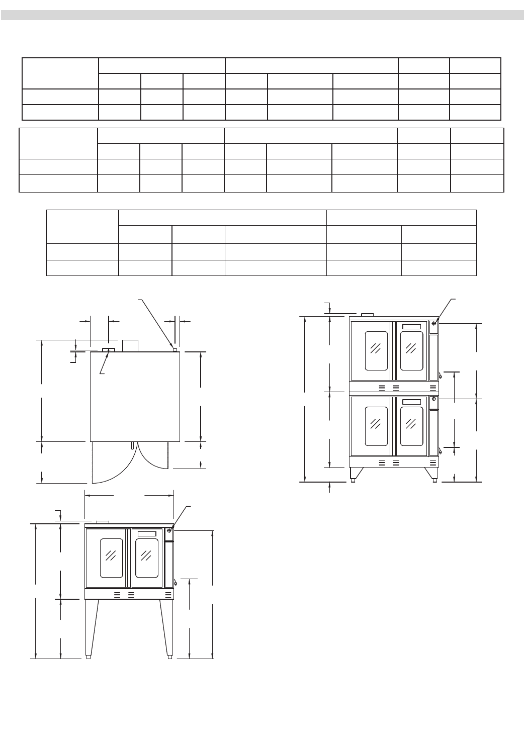
Installation Of Double Deck Models
A. Position insert in bottom leg opening and tap insert up
into leg till it seats at collar. Attach six inch (6") legs to
lower oven section. Raise unit or lay on its left side. Place
the front legs on the oven so as to line up with four (4)
attaching bolt holes. Secure leg to oven frame using (4)
3/8-16 x 3/4 bolts and washers provided. Repeat at rear of
unit.
B. Remove lower front cover of top deck (located under oven
doors). Raise top deck into place and line up body sides
and back of the unit. Fasten the rear of the units together,
with the stacking bracket, as shown, using (6) 1/4-20
machine screws, lock washers and nuts, (provided).
C. Install the interconnecting ue parts, carefully following
the instructions contained in the stacking kit. Pay
particular attention to the type of ovens you are stacking
and be sure to follow the corresponding instructions.
Part # MCOSM06 Rev 1 (11/03/08) Page 9
D. Assemble the stacking pipes provided in the stacking
kit as shown in the diagram at the top of this page. This
allows both ovens to be supplied by a single gas line. The
minimum recommended size of a single supply line for
two stacked ovens is 1 inch. Use a pipe thread compound
that is intended for use on propane gas piping and be sure
to check for leaks before nalizing the installation.
E. Check leveling of unit four (4) ways (using a common
carpenter's level on the rack inside the oven).
F. Plug the cord set of each unit into a 115-Volt power supply
outlet.
G. Maintain clearance from combustibles.
Each gas appliance shall be located with respect to building
construction and other equipment so as to permit access to
the appliance. Such access and clearance may be necessary
for servicing and cleaning.
3/4" Union
3" Nipple
3" Nipple
90 Degree Street Elbow
90 Degree Street Elbow
20-1/2" Nipple
3/4" to 1" Bell Reducer
CAUTION:
DISCONNECT BOTH UNITS FROM
ELECTRICAL SUPPLY BEFORE SERVICING.
POWER FAILURE
In the event of a power failure, no attempt
should be made to operate this oven.
IMPORTANT
All gas burners and pilots need sufficient
air to operate and large objects should not
be placed in front of this oven, which would
obstruct the airflow through the front.
Objects should not be placed on main top rear
of oven while in use. This could obstruct the
venting system of the unit's flue products.
Gas Connection
The 1" NPT inlet at the rear must be considered in piping the
gas supply for double stack units or 3/4" NPT for individual (or
single deck) connections. Undersized gas supply line(s) may
restrict the gas supply and aect performance. If other gas
appliances are supplied by the same supply line, the supply
line must be sized to carry the combined volume without
causing more than 1/2" pressure drop at the manifold of each
appliance on the line at full rate.
Recommended supply pressures are 7" WC, (NAT), and
11" WC, (PRO); ± 5%. (Must not exceed 13.8" WC [NAT], and
15" WC [PRO]).
Electrical Connection
A 15 AMP service must be provided for each oven. For 115
VAC usage, a cord and plug (NEMA #5-15P) is provided but
connection to the electrical service must be electrically
grounded in accordance with local codes, or in the absence of
local codes, with the National Electrical Code, ANSI/NFPA 70,
or the Canadian Electrical Code, CSA C22.2, as applicable.
This appliance is equipped with a three-prong (grounding)
plug for your protection against shock hazard and should
be plugged directly into a properly grounded three-prong
receptacle.
DO NOT CUT OR REMOVE THE
GROUNDING PRONG FROM THIS PLUG.
A wire diagram is axed to the rear of the unit.
Ventilation & Air Supply
Proper ventilation is highly important for good operation.
There are only two choices for properly venting an oven: 1)
canopy hood style or 2) direct venting. The ideal method
of venting a GAS Convection Oven is through the use of a
properly designed canopy, which should extend 6" (150 mm),
beyond all sides of the appliance and 6'6" (1950 mm) from the
oor.
Page 10 Part # MCOSM06 Rev 1 (11/03/08)
A strong exhaust fan will create a vacuum in the room. For an
exhaust system vent to work properly, exhaust and make-up
air must be balanced properly. For proper air balance contact
your local H.V.A.C. contractor.
All gas burners and pilots need sucient air to operate and
large objects should not be placed in rear and bottom of this
oven, which would obstruct the airow through the front.
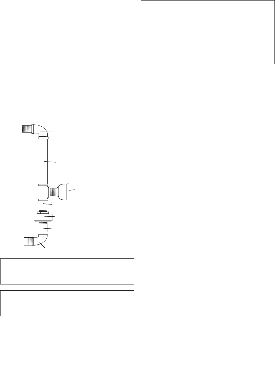
INSTALLATION OF A DIRECT FLUE.
When the installation of a canopy type exhaust hood is
impossible the oven may be direct vented. Before direct
venting check your local codes on ventilation, in the absence
of local codes, refer to the National Fuel Code NFPA 54, ANSI
Z223.1 (latest revision).
If the unit is to be connected directly to a direct ue, it is
necessary that draft diverter be installed to insure proper
ventilation.
DRAFT DIVERTER
Direct venting as described above, should be positioned
on the main top and fastened with sheet metal screws
provided. All parts described above are available from the
manufacturer.
NOTE: Each oven has been factory tested and adjusted prior
to shipment. It may be necessary to further adjust the oven
as part of a proper installation. Such adjustments are the
responsibility of the installer. Adjustments are not considered
defects in material and workmanship, and they are not
covered under the original equipment warranty.
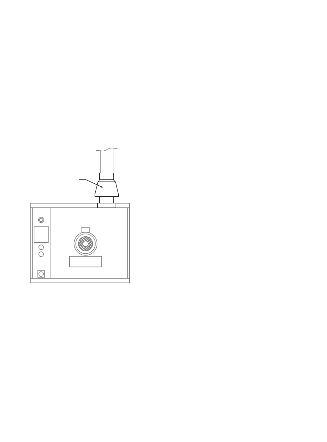
DO NOT UNDERSIZE VENT PIPE!
This can cause resistance to ow and impede good venting.
We suggest that if a horizontal run must be used it should
rise no less than 1/4" (6.25mm) for each linear foot of run, and
after a total of 180° of bends you should increase the size of
stove pipe by two (2") inches. The ue should rise 2' (60cm) to
3' (90cm) above the roof line or 2' (60cm) to 3' (90cm) above
any portion of a building within a horizontal distance of 10 (3
meters) feet.
The following diagram is only one example from the National
Fuel Gas Code Book NFPA 54, ANSI Z223.1, 7.5.3:

Part # MCOSM06 Rev 1 (11/03/08) Page 11
Termination Less than 10 feet (3 meters) from ridge Termination More than 10 feet (3 meters) from ridge
Less than 10 feet (3 meters)
More than 10' (3 meters)
2' (60cm)
Min. 3' (90cm) Min.
3' (90cm) Min.
Testing & Lighting Instructions
1. Turn on main gas valve. Remove the lower front cover
and the service panel above the control panel. Drop the
control panel and leak test all ttings and connections
upstream from the service valve located on the redundant
combination gas valve. Should any gas leaks be detected,
turn OFF main gas valve, correct the problem and retest.
2. Open shuto valve located on the redundant combination
gas valve. Activate control panel and set to desired
temperature. The pilot and burner is now ignited by direct
spark. Check all ttings again and correct any leaks and
recheck.
Replace all service panels and covers before operation.
NOTE: All electronic ignition systems are supplied with a
redundant gas valve. Therefore, the unit is not supplied with
an external pressure regulator.
NOTE: During installation there will be air in the gas line, this
air will have to bleed o before ignition can be established.
The electronic ignition system has a ninety second lock-out
as a safety device on all units. Therefore, several attempts
may be required before pilot ignition is established, wait ve
minutes after each attempt.
FOR YOUR SAFETY: KEEP YOUR APPLIANCE AREA FREE FROM
COMBUSTIBLES.
TO CONSERVE ENERGY:
Do not waste energy by leaving controls at high temperature
settings during idle periods. Lower settings will keep
oven warm and ready for next use period. Master 400
Series controls have an auto setback feature that is user
programmable to help with these applications.
Page 12 Part # MCOSM06 Rev 1 (11/03/08)
OPERATION
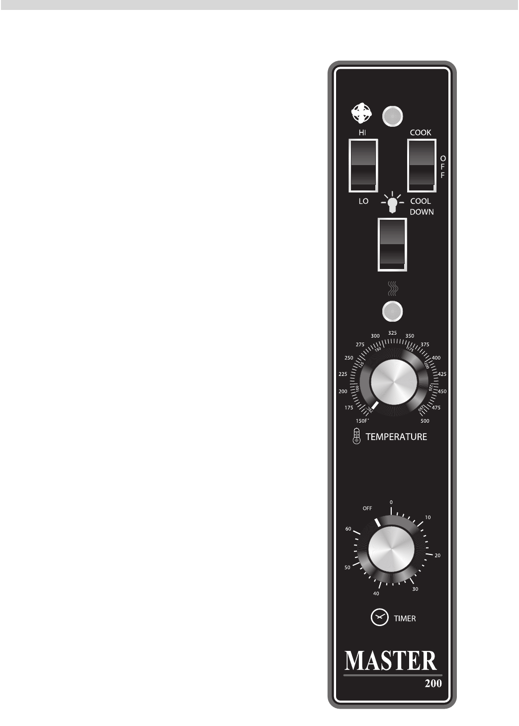
Master 200 Mechanical Control with Timer
In O Mode:
When the oven is o, there are no lights or indicators.
Start Up:
Press the Cook/O/Cool Down rocker switch to the "Cook"
position. The green lamp will light indicating the oven is
powered in cook mode.
The oven will begin to heat to the temperature set on the
thermostat dial. The amber lamp will light indicating the heat
is active. As the heat cycles on and o to maintain the set
temperature this light will go on and o accordingly.
The door must be closed for the oven to operate in cook
mode. Opening the door will cause the heat to stop. The
motor and fan will shut o. This is a safety feature.
Fan Speed:
The fan speed can be either high (1725 RPM) or (1150 RPM).
The fan speed is controlled by the left rocker switch marked
high and low.
Lights:
The oven lights are activated by pressing the light switch on
the control panel. This is a momentary switch and the lights
will stay lit as long as this button is held in the on position.
Lights will work whenever there is electrical power connected
to the oven.
Cool Down:
Pressing the Cook/O/Cool Down rocker switch to the Cool
Down position activates the fan and motor to cool the oven
cavity. The door must be open slightly for the fan and motor
to start. The heat is not active in this mode.
Optimal cool down will be achieved with the door open
slightly. Opening the door too far will shut the fan and motor
o. This is a patented safety feature.
Pressing the button to the OFF position cancels the cool
down and turns the oven o.
Temperature:
The temperature range is from 150°F to 500°F (66°C to 250°C)
is controlled by rotating the temperature dial and aligning the
indicator to the desired temperature.
Timer:
The timer is set by rotating the dial clockwise aligning the
indicator to the desired time cycle. The timer will count down
from 2 minutes to 60 minutes. At the end of the timing cycle
the buzzer will sound. The buzzer is turned o by rotating the
dial counter-clockwise to the o position as shown on the
control panel.
Part # MCOSM06 Rev 1 (11/03/08) Page 13
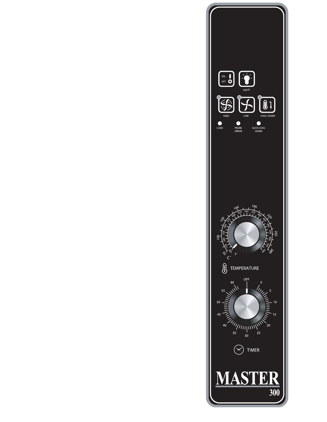
MASTER 300 Solid State Control
with Mechanical Timer
In O Mode:
When the controller is o, the unit will have no active
prompts. Pressing the ON/OFF key will activate the controller
into Start Up mode.
On Start Up:
In Start Up mode, the controller will heat to the temperature
indicated on the temperature control. The fan speed will
be that which was most recently set. When the oven cavity
reaches the set temperature and is ready for operation the
"LOAD" LED will light.
Controller Keys
Pressing the ON/OFF key will activate the oven.
Pressing the LIGHT key will turn the lights on for 30 seconds.
The lights will work if the controller is in the O mode. When
the door is opened, the light will come on and stay on for 30
seconds.
Pressing the FAN HIGH key will activate the higher speed fan
and light its LED.
Pressing the FAN LOW key will activate the lower speed fan
and light its LED.
Pressing the COOL DOWN key will deactivate the heat, turn
the fan on high and light its LED. The Cool Down will operate
when the door is closed or opened slightly. When the door
opens wider, the Cool Down mode will deactivate and the
LED will ash. This is a patented safety feature. Optimal cool-
down will be achieved with the door open slightly. If the
doors are closed, the LED will ash. Pressing the COOL DOWN
key again will turn the LED o and stop this mode. Pressing
the ON/OFF key will also cancel Cool Down.
When the door is opened the fan and heat will stop until the
door is closed. This is a patented safety feature.
When the ON/OFF key is pressed to turn the oven o and the
oven is above 200°F (93°C), the oven will go into an Auto Cool
Down mode. In Auto Cool Down, the oven will run the fan on
high until the oven cavity drops below 150°F (66°C). During
this time the "AUTO COOL DOWN" LED will light. When the
oven temperature drops below 150°F (66°C) the oven turns
o. This feature protects the oven motor from pre-mature
failure. Optimal cool-down will be achieved with the door
open slightly. Controller Dials.
Cooking TEMPERATURE is set by rotating the TEMPERATURE
dial to the desired temperature, 150°F (66°C) to 550°F (288°C).
Cooking TIME is set by rotating the TIMER dial to the desired
cooking time, up to 60 minutes.
Page 14 Part # MCOSM06 Rev 1 (11/03/08)
NOTE: The "PROBE ERROR" LED will light if the oven
temperature probe is malfunctioning or has become
damaged or disconnected. Call for service if this occurs.
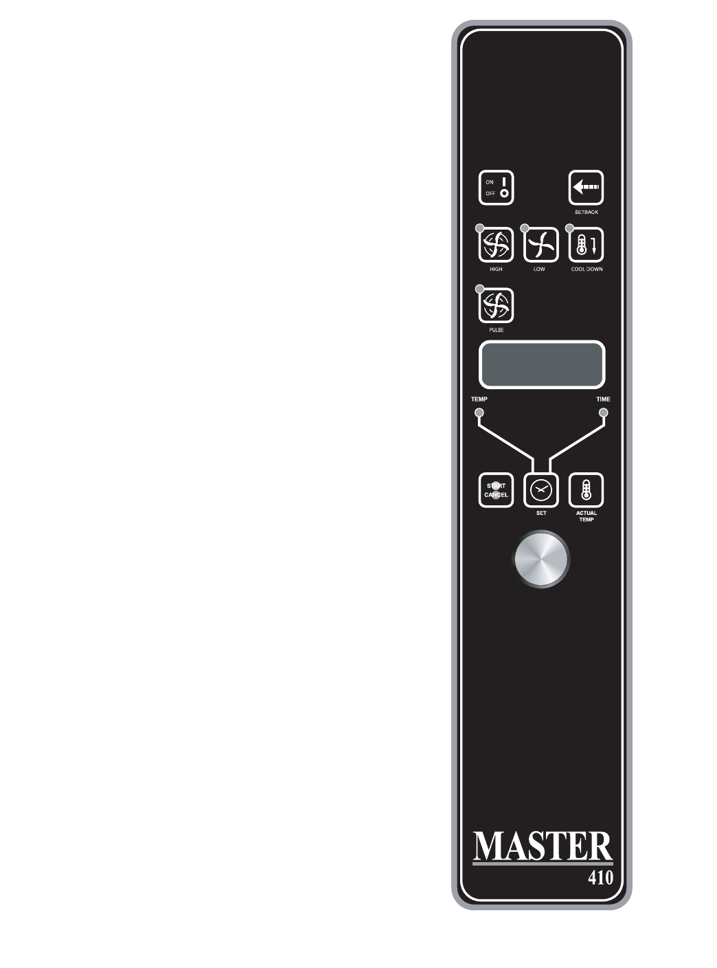
MASTER 410 ELECTRONIC CONTROL
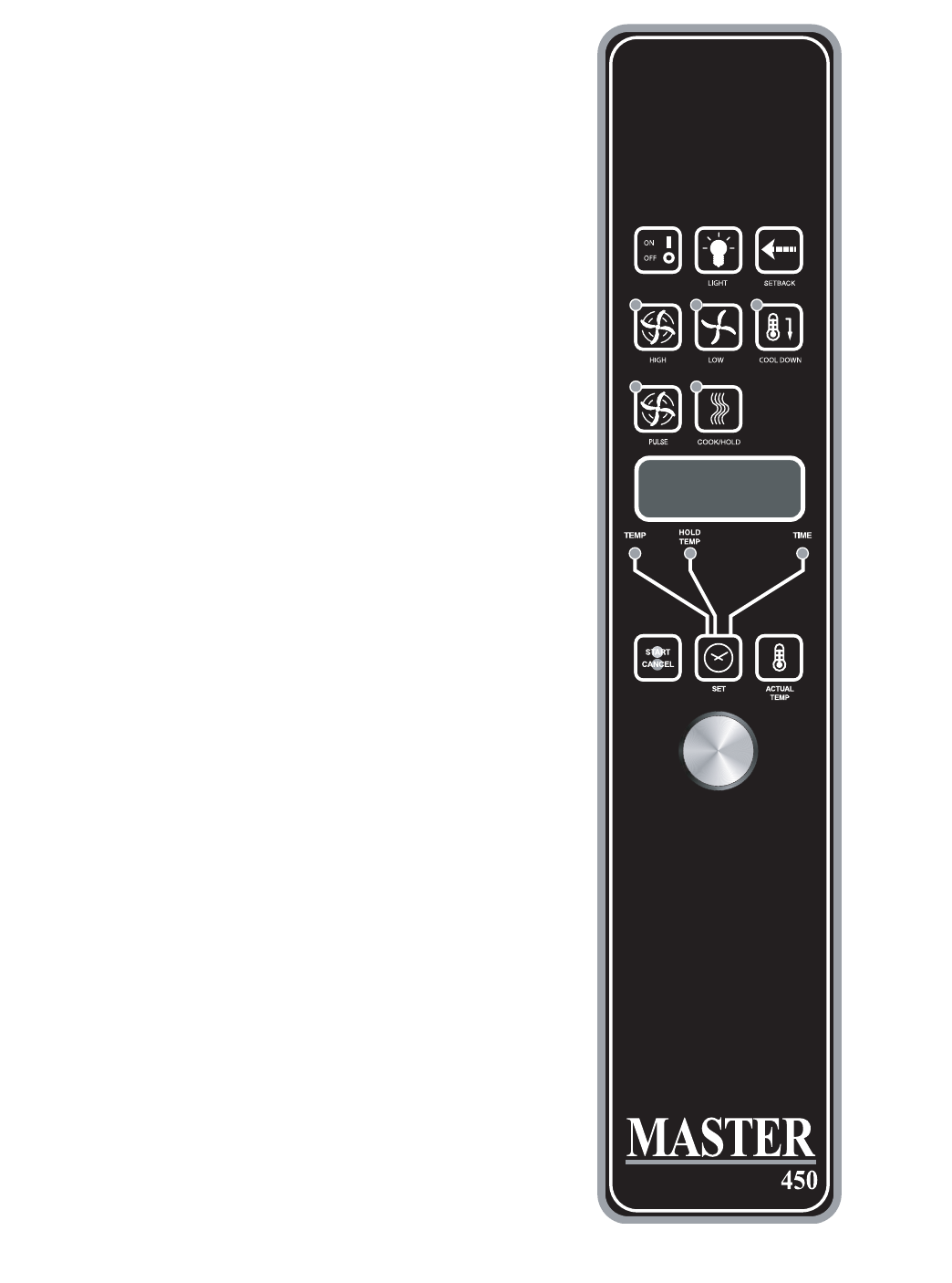
MASTER 450 ELECTRONIC CONTROL
WITH COOK-N-HOLD
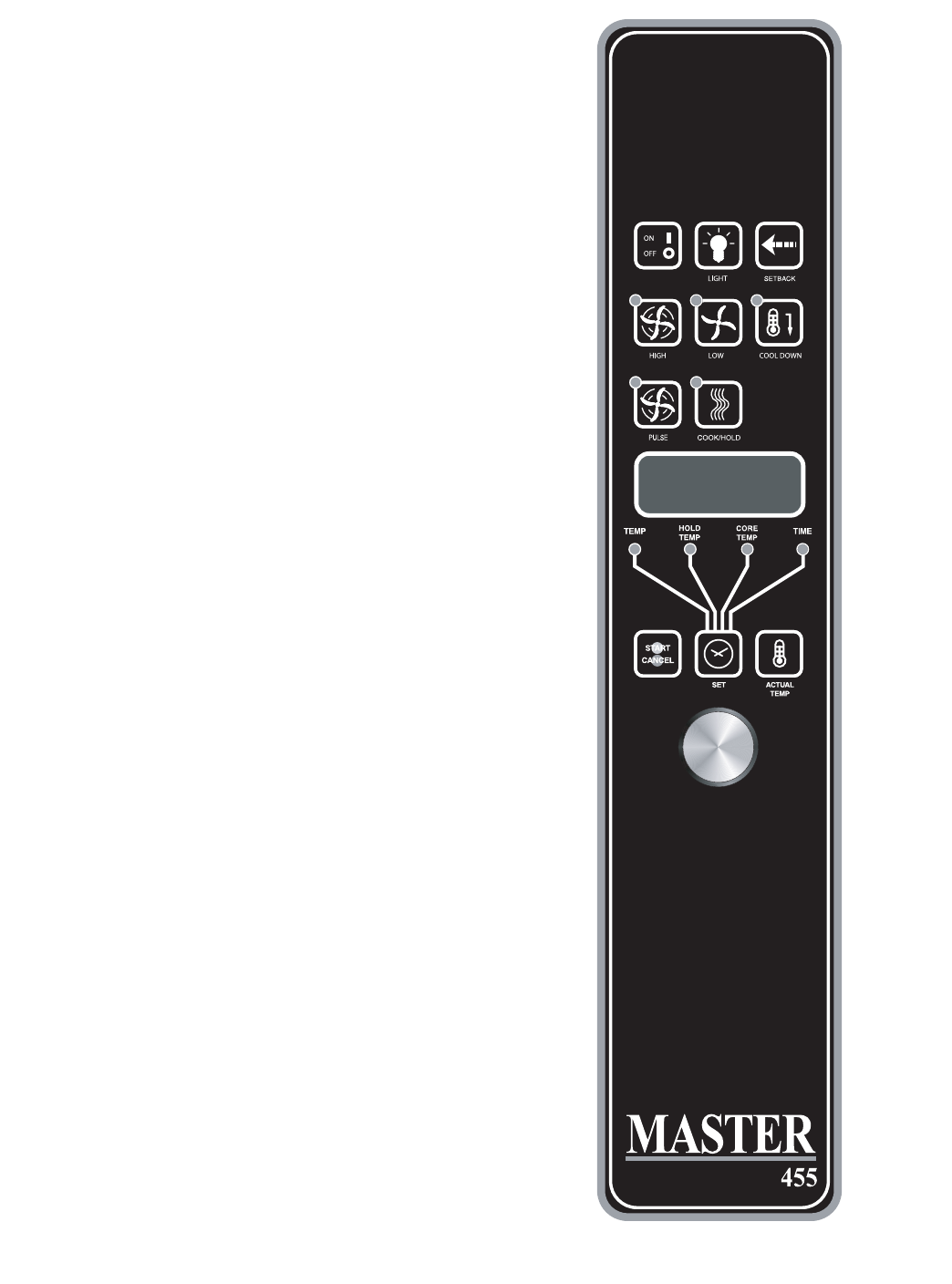
MASTER 455 ELECTRONIC CONTROL WITH
COOK-N-HOLD & CORE PROBE
In O Mode:
When the controller is o, the display will show "OFF".
Pressing the ON/OFF key will activate the controller into Start
Up mode.
On Start Up:
In Start Up mode, the controller will heat to the last set
temperature, time and fan speed. The factory defaults are
350°F (177°C), 30 minutes and low fan speed. The display will
indicate "LO" when the oven is below the set temperature.
When the oven cavity reaches the set temperature and is
ready for operation the display will indicate "LOAD".
NOTE: If the oven temperature goes above the requested
temperature the display will indicate "HI". If the oven
temperature goes above 575°F (302°C) the display will
indicate "HELP" and an audible signal will sound. This is a
safety feature.
If the door is opened during a Cooking mode, the fan and
heat will stop, and the display will indicate "DOOR" until the
door is closed. This is a patented safety feature.
Pressing the ACTUAL TEMP key will display the actual oven
temperature in 5° increments. Controller Keys.
Pressing the ON/OFF key will activate the oven.
Pressing the LIGHT key will turn the lights on for 30 seconds.
The lights will work if the controller is in the O mode. When
the door is opened, the light will come on and stay on for 30
seconds.
Pressing the FAN HIGH key will activate the higher fan speed
and light its LED.
Pressing the FAN LOW key will activate the lower fan speed
and light its LED.
Pressing the FAN PULSE key will activate the lower fan speed
and light its LED. The fan will be active for 30 seconds then o
for 30 seconds, and continues this cycle.
Part # MCOSM06 Rev 1 (11/03/08) Page 15
Pressing the SETBACK key will cool the oven cavity to a
preprogrammed temperature (factory set at 250°F [121°C]).
The oven will automatically go into Setback mode after the
pre-programmed non-usage time, (see 'Changing Factory
Setback Program'). The display will indicate "SETB". This is an
energy-saving feature.
Pressing the COOL DOWN key will deactivate the heat, turn
the fan on high and light its LED. The display will indicate
"OPEN DOOR" if the door is closed, prompting the user to
open the door slightly. With the door open slightly the display
will indicate "COOL". The Cool Down will operate when the
door is closed or opened slightly. Optimal cool-down will be
achieved with the door open slightly. When the door opens
wider, the Cool Down mode will deactivate and the display
will indicate "DOOR". This is a patented safety feature. Pressing
the COOL DOWN key again will turn the LED o and stop this
mode. Pressing the ON/OFF key will also cancel Cool Down.
Cool Down is not active during a cook.
When the ON/OFF switch is pressed to turn the oven o and
the oven was above 200°F (93°C), the oven will go into an
Auto Cool Down mode. In Auto Cool Down, the oven will
run the fan on high until the oven cavity drops below 150°F
(66°C). During this time the display will indicate "AUTO".
When the oven temperature drops below 150°F (66°C) the
oven turns o. This feature protects the oven motor from pre-
mature failure. Optimal cool-down will be achieved with the
door open slightly.
Operating the Controls
Setting the cook temperature and time are done in the same
manner. Pressing the SET key will light the TEMP LED. The
operator then sets the temperature by rotating the dial on
the controller until the desired temperature is shown on the
display. Pressing the SET key a second time lights the TIME
LED and allows the operator to select the desired cook time as
shown on the display. Pressing the SET key a third time ends
the programming.
Pressing the START/CANCEL key will start the timing cycle.
The display will count down from the Set time in minutes and
seconds (solid colon) or hours and minutes (blinking colon)
the minutes and seconds. When the cycle is completed,
processing this key will also cancel the "DONE" prompt. To
cancel a timing cycle in progress, press and hold the START/
CANCEL key for 3 seconds.
Cook-N-Hold Operation
Pressing the COOK/HOLD (450 and 455 Controllers Only) key
activates the Cook-N-Hold mode and lights its LED. To verify
the proper hold temperature has been selected, press the SET
key twice. The display will show the hold temperature. At the
end of the cook cycle, an audible alarm will sound, the display
will ash "DONE" and change to count "UP" the hold time.
The oven will switch to the programmed hold temperature.
Page 16 Part # MCOSM06 Rev 1 (11/03/08)
Setting the cook temperature, hold temperature and time
are done in the same manner. Pressing the SET key will
light the TEMP LED. The operator then sets the temperature
by rotating the dial on the controller until the desired
temperature is shown on the display. Pressing the SET key a
second time will light the HOLD LED and allows the operator
to select the desired hold temperature as shown on the
display. Pressing the SET key a third time lights the TIME LED
and allows the operator to select the desired cook time as
shown on the display. Pressing the SET key a fourth time ends
the programming.
Pressing the START/CANCEL key will start the timing cycle.
When the cycle is completed, pressing this key will also cancel
the "DONE" prompt. To cancel a timing cycle in progress press
and hold the START/CANCEL key for 3 seconds.
Core Probe Operation
The Core Probe option (455 Controller Only) is only active
when the core probe is plugged into its connector. To set the
core temperature, rst plug the core probe into its connector.
The display will indicate "100" and the CORE TEMP LED will
be on. The operator then sets the temperature by rotating
the dial on the controller until the desired temperature is
shown on the display. Pressing the SET key stores the core
temperature and starts the cooking process.
To set the oven temperature, press the SET key again. The
TEMP LED will light and the oven temperature can be
set by rotating the dial on the controller until the desired
temperature is displayed. Pressing the SET key again will
light the HOLD LED allowing the operator to set the hold
temperature in the same manner.
NOTE: If the hold temperature is not set, the default hold
temperature is 150°F (66°C) or the last programmed
temperature. (Hold temperature range is 140°F (60°C) to
210°F (99°C).
When the core temperature is reached, the display will sound
and ash "DONE" for 3 seconds. Automatically, the display
will switch to count "UP" the time the oven is on hold.
CHANGING FACTORY SETBACK PROGRAM
To change the factory setback settings, press and hold the
SETBACK key for two seconds. The TEMP LED will light and
a temperature will be displayed (factory preset at 250°F
[121°C]). Set the temperature using the dial, then press the
SET key. The TEMP LED will go out and the TIME LED will light.
Set the time using the dial, then press the SET key. Press the
SET key one more time to exit programming.
Note: To disable the setback function, set the temperature to
250º F (121ºC) and the time to zero..
Part # MCOSM06 Rev 1 (11/03/08) Page 17
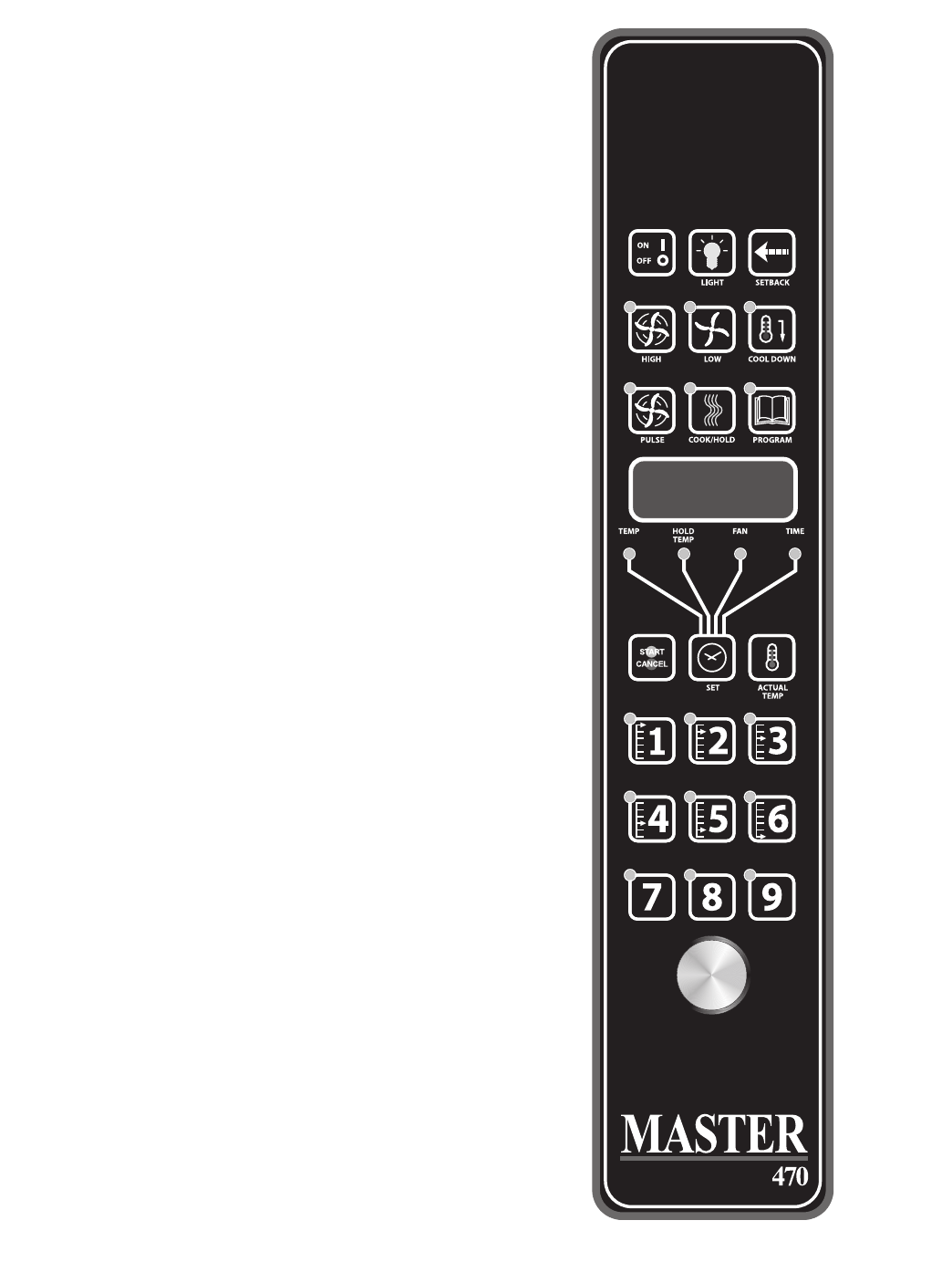
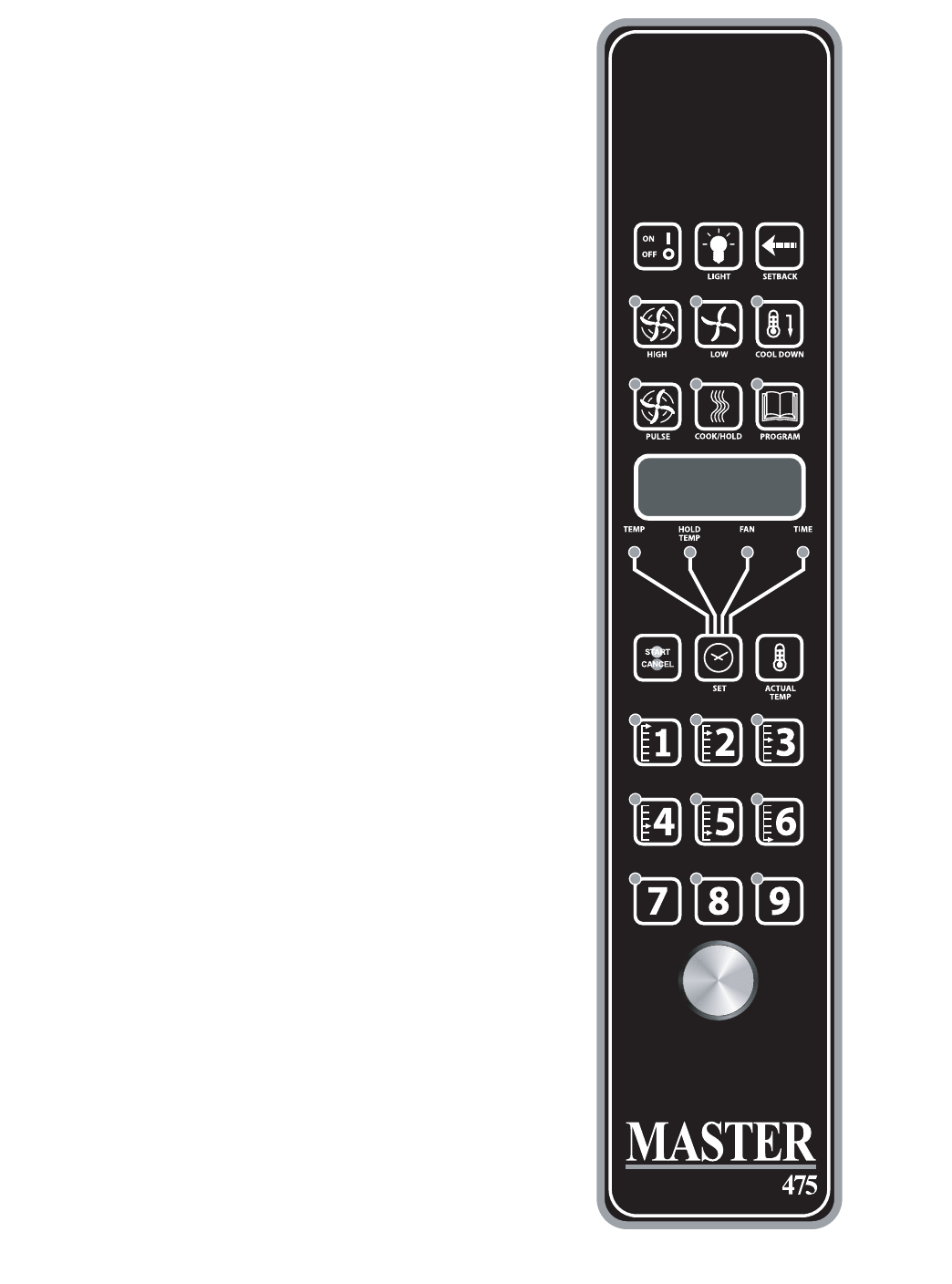
MASTER 470/475 ELECTRONIC
PROGRAMMABLE CONTROL
Manual cooking:
1. Press SET key - TEMP LED will light.
2. Set temperature using the dial (factory preset at 350°F).
3. Press SET key - FAN LED will light.
4. Select fan mode using one of the three (3) fan keys
(HIGH, LOW, PULSE) - the selected fan LED will light.
5. Press SET key - TIME LED will light.
6. Set cook time using the dial (factory preset at 30:00).
7. Press SET key - ready to cook.
8. Press START/CANCEL to begin manual cooking.
Manual cooking using Cook-N-Hold:
1. Press the COOK/HOLD key, that key's LED will light.
2. Press SET key - TEMP LED will light.
3. Set cook temperature using the dial (factory preset at
350°F).
4. Press SET key - HOLD LED will light.
5. Set hold temperature using the dial (factory preset at
200°F).
6. Press SET key - FAN LED will light.
7. Select fan mode using one of the three (3) fan keys
( HIGH, LOW, PULSE ) - the selected fan LED will light.
8. Press SET key - TIME LED will light.
9. Set cook time using the dial (factory preset at 30:00).
10. Press SET key - ready to cook.
11. Press START/CANCEL to begin manual cooking.
Programming Product Keys (Master ):
NOTE: Cooking time(s) is the element of the program that tells
the controller that other information (temperature, fan
speed, etc.) will be inputted into the controller. The rst
step is to enter all the time periods required, followed by
the addition of the other cooking elements.
Page 18 Part # MCOSM06 Rev 1 (11/03/08)
1. Press and hold PROG key for three (3) seconds - all the
product key LEDs light.
2. CODE will be displayed. The controller is asking for the
access code. Press 4-2-7-5 and the START/CANCEL key.
PROD will be displayed indicating you have gained access
to Product Programming.
3. Press the product key (1 - 9) into which you want to store
a cooking program. SHLF will be displayed. The control is
asking if you want to program the key as a shelf timer or
with a cooking prole. Select your answer by pressing the
START/CANCEL key. When the correct answer is displayed,
press the SET key. The TIME LED will light. 30:00 will be
displayed.
4. Set rst cook time using dial. If more than one cooking
prole is desired:
•presstheproductkeywheretheprogramistobestored
(1 - 9) - PR-2 will be displayed.
•setthesecondcooktimeusingthedial(factorypresets
for PR-2 through PR-5 are :00).
•pressthesameproductkey(1-9)again-PR-3willbe
displayed.
•Repeatthisprocessforallproles.Whenthelastprole
time has been entered, press the SET key, OR
If less than ve (5) proles are desired press the SET key
after the last required prole - PRE will be displayed,
followed by :00. The controller is asking if you would like a
reminder alarm (pre-alarm) to sound during the cooking
process. (factory preset is :00).
5. If a pre-alarm signal is desired - dial in the time that the
alarm is to sound. (Ex. If the product is to be turned
halfway through the 60 minute cooking cycle, set the
pre-alarm to 30 minutes). If pre-alarm is not desired verify
that ":00" is displayed. Press the SET key - TEMP Led will
light, and the display will show the rst prole cooking
temperature. (factory preset at 350°F).
6. Set the rst cooking temperature using the dial.
Press the product key - PR-2 will be displayed followed by
the second temperature.
Set the second cooking time using the dial.
Repeat as you did for cooking time, for all the proles
desired.
NOTE: The controller will only accept cooking temperatures
for the number of proles for which a cooking time
has been set. If the product key is pressed after the
last programmed prole, the rst temperature will be
displayed.

Part # MCOSM06 Rev 1 (11/03/08) Page 19
Press SET after the last cooking temperatures has been
entered, HOLD will be displayed.
7. Use the START/CANCEL key to select yes or no. Press the
SET key.
8. If yes was selected, the HOLD LED will light. Enter the hold
temperature using the dial. (factory preset at 200°F) Press
the SET key. FAN will be displayed and the FAN LED will
light.
Set the fan speed desired for the rst cooking prole using
the individual fan keys (HIGH, LOW or PULSE), press the
product key and set the fan speed for the second cooking
prole. Continue until all the proles have been assigned
a fan speed. Press the SET key when complete. As with the
temperature, if the product key is pressed after the last
programmed prole, the rst fan speed will be displayed.
9. FL or St will be displayed (for ex time or straight time)
(factory preset for ex time). Select ex or straight time
using the START/CANCEL key for the rst prole. Press
the product key and select straight time or ex time for
the second prole. Continue until all the proles have
been assigned straight or ex time. Press the SET key
when complete. If the product key is pressed after the last
programmed prole, the rst prole will be displayed.
10. Programming for that product key is complete.
Programming Product Keys (Master ):
NOTE: The Master 470 controller will only accept a single
cooking prole per product key (one cooking time, one
cook temperature, one fan speed, and one choice for
straight or ex time).
Press and hold PROG key for three (3) seconds - all the
product key LEDs light.
1. CODE will be displayed. The controller is asking for the
access code. Press 4-2-7-5 and the START/CANCEL key.
PROD will be displayed indicating you have gained access
to Product Programming.
2. Press the product key (1 - 9) into which you want to store
a cooking program. SHLF will be displayed. The control
is asking if you want to program the key as a shelf timer
or a cooking prole. Select your answer by pressing the
START/CANCEL key. When the correct answer is displayed,
press the SET key. The TIME LED will light. 30:00 will be
displayed.
3. Set the cook time using dial.
Press the SET key - PRE will be displayed, followed by :00.
The controller is asking if you would like a reminder alarm
(pre-alarm) to sound during the cooking process. (factory
preset is :00).
4. If a pre-alarm signal is desired - dial in the time that
the alarm is to sound. (Ex. If the product is to be turned
halfway through the 60 minute cooking cycle, set the pre-
alarm to 30 minutes). If pre-alarm is not desired verify that
":00" is displayed.
•PresstheSETkey-TEMPLedwilllight,andthedisplay
will show the cooking temperature. (factory preset at
350°F).
5. Set the cooking temperature using the dial.
Press the SET key. - FAN will be displayed and the FAN LED
will light.
6. Set the fan speed desired using the individual fan keys
(HIGH, LOW or PULSE).
Press the SET key. - FL or St will be displayed (for ex time
or straight time) (factory preset for ex time).
7. Select ex or straight time using the START/CANCEL key.
Press the SET key when complete.
8. Programming for that product key is complete.
Cooking Using The Product Keys
(Master and Master ):
1. On initial start-up, press the product key for the menu
item to be cooked. Wait until LOAD is displayed.
2. Load the oven.
3. Press the product key for the loaded menu item.
4. Press the START/CANCEL key.
5. To cancel the alarm or the hold, press the START/CANCEL
key followed by the product key.
Verifying hold time (Master and Master ):
While a product is being held, press and hold the product
key. The actual hold time will be displayed.
Selecting Fahrenheit or Celsius (Master 475 and Master
470):
Press PROG and ACTUAL TEMP keys at the same time, F or
C will be displayed. (factory preset for F)
Press the START/CANCEL key to switch between F and C,
When the desired setting is displayed press the PROG and
ACTUAL TEMP keys at the same time.

Page 20 Part # MCOSM06 Rev 1 (11/03/08)
Cooking with the Shelf Timer
(Master and Master ):
The shelf timer option is used to independently time each of
the up to six dierent shelves or racks within the oven.
NOTE: To use the shelf timer option, at least one product
key must be programmed with a cooking prole
(temperature, time, fan speed, ex or straight time). The
program key must be limited to a single cooking prole
to be used with the shelf timing option. If more than one
product key is to be used, all product keys to be used must
feature the same cooking temperature and fan speed. Flex
or straight time and cooking time can de dierent. The
Cook-N-Hold option can not be used with the shelf timer
operation.
Pressing the desired product key will bring the oven to the
desired cooking temperature, once the oven has reached
the proper cooking temperature as indicated by LOAD in the
display.
1. Press the product key containing the desired cooking
prole (1 - 9).
2. Press the shelf key for the shelf location to be timed (1 - 6).
NOTE: product keys and shelf keys are the same keys.
3. Press the START/CANCEL key to begin the cooking/timing
process.
4. When the cooking/timing process is complete for each
shelf, an audible "done" signal will sound and the display
will indicate which shelf is nished. Example: SH-1
5. To turn o the alarm press the product key with the
ashing LED.
Example: Two product proles contain the same cooking
temperature, fan speed and are both programmed for ex
time - keys 1 and 6.
Two trays of product are going to be cooked in the oven at
the same time. The rst tray will use product key 1 and will be
placed in rack position 2. The second tray will use product key
6 and will be placed in rack position 4. Once the oven display
indicates LOAD:
1. Load food product into oven on shelf 2.
2. Press product key 1, then shelf key 2.
3. Press the START/CANCEL key to start cooking on shelf 2.
4. Load food product into oven on shelf 4.
5. Press product key 6, then shelf key 4.
6. Press the START/CANCEL key to start cooking on shelf 4.
7. When product on shelf 2 is nished cooking, an audible
alarm will sound and the display will ash DONE, then
SH-2, and the product key 1 LED will be ashing.
8. To turn o the alarm, press product key 1.
9. When product on shelf 4 is nished cooking, an audible
alarm will sound and the display will ash DONE, then
SH-4, and the product key 6 LED will be ashing.
10. To turn o the alarm, press product key 6.

Part # MCOSM06 Rev 1 (11/03/08) Page 21
1. Preheat oven thoroughly (approximately. 20 minutes)
before use.
2. As a general rule, temperature should be reduced 25°
to 50° from that used in a standard/conventional oven.
Cooking time may also be shorter, so we suggest closely
checking the rst batch of each product prepared.
3. Use the chart of suggested times and temperatures as a
guide. These will vary depending upon such factors as size
of load, temperature and mixture of product (particularly
moisture) and density of product.
4. Keep a record of the times, temperature and load sizes you
establish for various products. Once you have determined
these, they will be similar for succeeding loads.
5. When practical, start cooking the lowest temperature
product rst and gradually work up to higher
temperatures.
6. If you nd that your previous temperature setting is more
that 10° higher than needed for succeeding loads, press
the COOL DOWN key to reach the desired temperature
before setting a new cooking temperature.
7. When loading oven, work as quickly as possible to prevent
loss of heat.
8. Oven will continue to heat even though the timer goes
o. Product should be removed from the oven as soon as
possible to avoid over cooking.
9. Center pans on racks and load each shelf evenly to allow
for proper air circulation within the cavity.
10. When baking, weigh or measure the product in each pan
to assure even cooking.
11. When cooking six pans, use rack positions 2, 4, 6, 8, 10 and
12, starting from the top.
12. Do not overload the oven. Six pans are suggested for most
items, i.e., cakes, cookies, rolls, etc. However, the maximum
(13 pans) may be used for sh sticks, chicken nuggets and
hamburgers. Cooking times will have to be adjusted.
13. Mun pans should be placed in the oven back to front or
with the short side of the pans facing the front. This results
in the most evenly baked product.
14. When re-thermalizing frozen casseroles, preheat the oven
100° over the suggested temperature. Return to cooking
temperature when the oven is loaded. This will help
compensate for the introduction of a large frozen mass
into the cavity.
15. Use pan extenders or two inch deep 18"x26" pans for
batter type products which weigh more than eight
pounds, i.e., Pineapple Upside Down Cake.
16. Never place anything directly on the bottom of the oven
cavity. This obstructs the airow and will cause uneven
results.
NOTE: Moisture will escape around the doors when baking
products with heavy moisture content, such as: chicken,
potatoes, etc.
PERFORMANCE RECOMMENDATIONS
Page 22 Part # MCOSM06 Rev 1 (11/03/08)
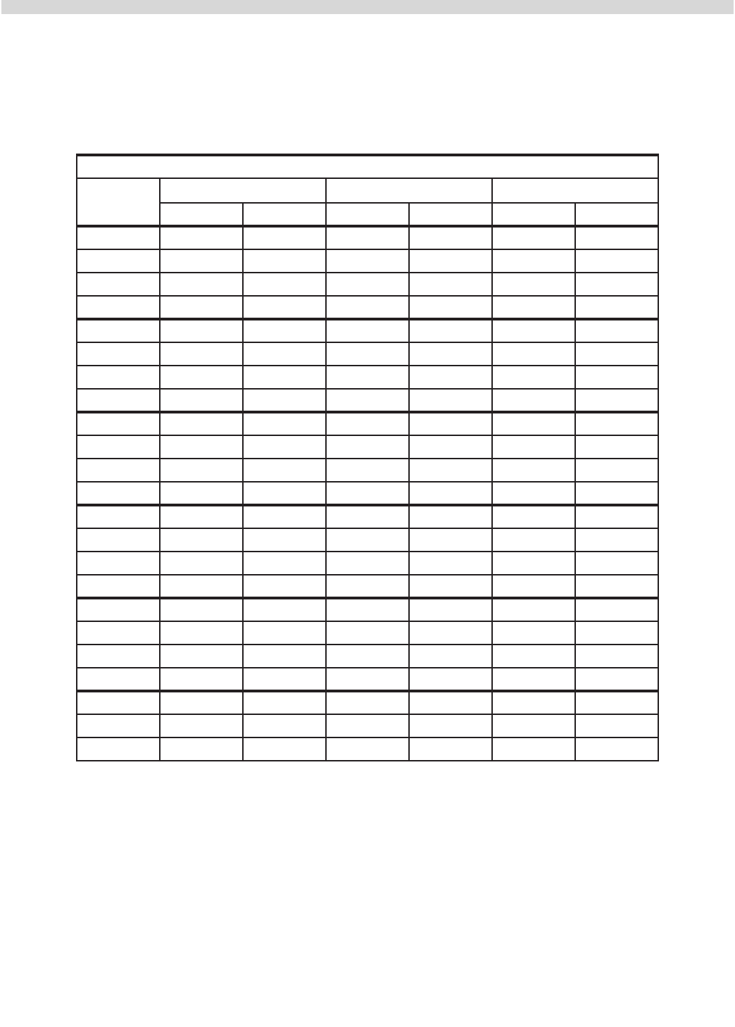
The following suggested times and temperatures are provided as a starting guide. Elevation, atmospheric conditions, gas
supply, recipe, cooking pans and oven loading may aect your actual results.
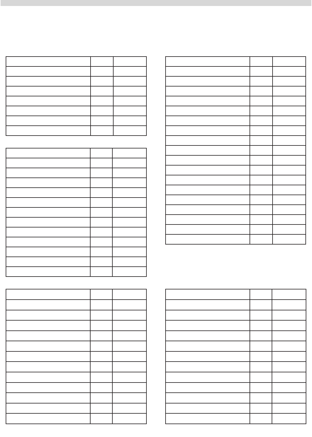
COOKING GUIDE
Product °F Time
White Sheet Cakes – 5 lb 300° 20 min
White Sheet Cakes – 6 lb 300°
Yellow Layer Cake – 21 oz 325° 15 min
Yellow Sheet Cake – 5 lb 300° 22 min
Chocolate Layer Cake – 21 oz 300° 22 min
Angel Food Cake 375° 22 min
Brownies 350° 15 min
Product °F Time
Chicken Parts 350° 45 min
Hamburger Patties, 10/lb fzn 350° 8 min
Hamburger Patties, 10/lb fresh 350° 5 min
Hamburger Patties, 4/lb fzn 350° 12 min
Hamburger Patties, 4/lb fresh 350° 8 min
Meatloaf – 4# 325° 45 min
Bacon 350° 10 min
Roast Beef - 20# 325° 3 hr 15 min
Prime Rib - 10# 300° 1 hr 45 min
Stued Pork Chops 350° 45 min
Lamb Chops 375° 40 min
Boneless Veal Roast 300° 3 Hr
Product °F Time
Soda Biscuits 400° 6 min
Yeast Rolls 325° 24 min
Sweet Bread 325° 24 min
Corn Bread 350° 22 min
Gingerbread 300° 24 min
Apple Turnovers 350° 25 min
Cream Pus 300° 25 min
Sugar Cookies 325° 12 min
Chocolate Chip Cookies 375° 8 min
Apple Pie (Fresh) 375° 25 min
Blueberry Pie (Fresh) 350° 30 min
Blueberry Pie (Frozen) 300° 56 min
Pumpkin Pie (Frozen) 300° 50 min
Frozen Pizza 300° 6 min
Macaroni & Cheese 350° 15 min
Fish Sticks 350° 16 min
Stued Peppers 350° 45 min
Baked Potatoes 350° 60 min
Product °F Time Product °F Time
Part # MCOSM06 Rev 1 (11/03/08) Page 23
Please refer to the operating instructions to program the 450 and 455 control units for cook and hold feature. The times and
temperatures listed below are to be used as a starting guide. Your actual results may vary greatly depending on your elevation,
gas supply, atmospheric conditions and other items being cooked at the same time.
COOK AND HOLD
Time in Hours
Weight in
lbs
Temperature: 200°F Temperature: 250°F Temperature: 300°F
Rare Medium Rare Medium Rare Medium
8 2.5 3.5 1.5 2 1.25 1.5
9 2.75 3.75 1.75 2.25 1.25 1.75
10 3 4.25 2 2.5 1.5 1.75
11 3.25 4.5 2 2.75 1.5 1.75
12 3.5 5 2.25 3 1.5 2
13 3.75 5 2.5 3.25 1.5 2.25
14 4 5.75 2.5 3.5 1.75 2.5
15 4.25 6 2.75 3.5 2 2.5
16 4.5 6.25 2.75 3.75 2 2.75
17 4.75 6.5 3 4 2.25 2.75
18 4.75 6.75 3.25 4.25 2.25 3
19 5 7.25 3.25 4.25 2.25 3
20 5.25 7.5 3.5 4.5 2.5 3.25
21 5.5 7.75 3.5 4.75 2.75 3.5
22 5.75 7.75 3.5 4.75 2.75 3.5
23 6 8.25 3.75 5 2.75 3.75
24 6 8.75 3.75 5 2.75 3.75
25 6.25 9 4.25 5.5 3 4
26 6.5 9.25 4.25 5.5 3.25 4.25
27 6.75 9.5 4.25 5.75 3.25 4.25
28 7 9.75 4.5 6 3.25 4.25
29 7.25 10 4.75 6.25 3.5 4.5
30 7.25 10.25 4.75 6.25 3.5 4.5
Page 24 Part # MCOSM06 Rev 1 (11/03/08)
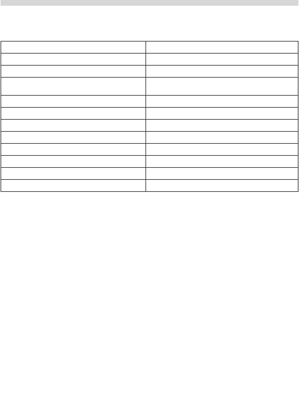
Problem Solution
If cakes are dark on the sides and not done in the center Lower oven temperature.
If cakes edges are too brown Reduce number of pans or lower oven temperature.
If cakes have light outer color Raise temperature.
If cake settles slightly in the center Bake longer or raise oven temperature slightly.
Do not open doors too often or for long periods.
If cake ripples Overloading pans or batter is too thin.
If cakes are too coarse Lower oven temperature.
If pies have uneven color Reduce number of pies per rack or eliminate use of bake pans.
If cupcakes crack on top Lower oven temperature.
If meats are browned and not done in center Lower temperature and roast longer.
If meats are well done and browned Reduce time. Limit amount of moisture.
If meats develop hard crust Reduce temperature or place pan of water in oven.
If rolls have uneven color Reduce number or size of pans.
PROBLEMS / SOLUTIONS

Part # MCOSM06 Rev 1 (11/03/08) Page 25
CLEANING & MAINTENANCE
NOTE: Disconnect line cord from power supply before
cleaning or servicing.
Break-In Period
When oven is new, operate it for one hour at 450°F before you
begin your normal cooking operation. After cooling, wipe the
interior, including the racks, with a clean damp cloth.
Exterior Cleaning
Establish a regular schedule. Any spills should be wiped o
immediately.
1. The oven should always be allowed to cool suciently
before any cleaning is attempted.
2. Wipe exposed, cleanable surface when cool with a mild
detergent and hot water. Stubborn residue spots may be
removed with a lightweight non-metallic scouring pad.
Dry thoroughly with a clean cloth.
3. Painted surfaces should be cleaned using a mild soap
and warm water solution on a sponge or soft Cloth. Dry
thoroughly.
4. Stainless Steel surfaces can often be cleaned adequately
with the same method. Stubborn stains may be removed
by using a non-metallic abrasive pad, rubbing in the
direction of the metal's grain. If necessary, for particularly
heavy deposits, you may mix a thin paste of water and
scouring powder, and apply it with a sponge. Be careful
to apply light pressure and remember to rub only in the
direction of the grain in the metal.
5. The control panel surface is easily cleaned with hot water,
soap and a soft cloth. Do not use hard abrasives, solvent
type materials or metallic scouring pads since these will
scratch or cloud the surface.
6. Never spray the perforated areas or control panel with
steam or water, as this will allow moisture into the control
cavity, which could damage electrical components.
Interior Cleaning
Establish a regular cleaning schedule or wipe o on the same
day when spillovers occur.
1. Cool down oven.
2. Remove oven racks.
3. Lift rack guides on either side of oven o of holders. Racks
and guides may be run through dishwasher while oven
cavity is being cleaned.
4. Clean with soap and water using a non-metallic scouring
pad, if necessary. If dirt and grease have accumulated, a
mild ammonia solution or commercial oven cleaner such
as Easy-O or Dow may be used.
5. To reinstall, reverse procedure. Place the bottom of the
rack guide against the cavity wall. Keeping the top pulled
away from the wall lift up. Push the top of the rack guide
against the wall and push down locking it into place.
Fan Area Maintenance
If aluminum foil is routinely used to wrap food or cooking
vessels during oven operation, the following preventive
maintenance must be performed:
1. Turn power switch to "OFF" position.
2. Remove oven racks and rack guides.
3. Remove air bae and clean any stains or deposits.
4. Check blower wheel and air bae for particles of
aluminum foil or food deposits. Clean ns of blower
wheel. (Caution: edges of blower wheel ns may be
sharp).
5. Reinstall the air bae, rack guides and oven racks.
This simple practice, if performed on a regular basis will
keep your Garland oven operating at peak performance.

Page 26 Part # MCOSM06 Rev 1 (11/03/08)
MOTOR CARE
The motor on your convection oven is maintenance free since
it is constructed with self-lubricating sealed ball bearings.
It is designed to provide durable service when treated with
ordinary care. We have a few suggestions to follow on the
care of your motor. When the motor is operating, it cools
itself internally by air entering at the rear of the motor case,
provided proper clearance has been allowed.
Since the blower wheel is in the oven cavity it is at the same
temperature as the oven. If the motor is stopped while the
oven is hot, the heat from the blower wheel is conducted
down the shaft and into the armature of the motor. This
action could shorten the life of the motor.
We recommend, at the end of the bake or roasting period,
when the oven will be idle for any period of time, or before
shutting down completely, that the doors be left open
slightly, and press the COOL DOWN key on the control panel.
The fan will continue to run until the oven cools down to
150°F (66°C). At the end of the day, press the ON/OFF key to
activate the Auto Cool Down feature. The fan will run on high
until the oven cavity drops below 150°F (66°C). During this
time the "AUTO COOL DOWN" LED will light. When the oven
temperature drops below 150°F (66°C) the oven turns o.
This feature protects the oven motor from pre-mature failure.
Optimal cool-down will be achieved with the door open
slightly.

Part # MCOSM06 Rev 1 (11/03/08) Page 27
Section Two
Electronic Pilot
& Main Burner
Page 28 Part # MCOSM06 Rev 1 (11/03/08)
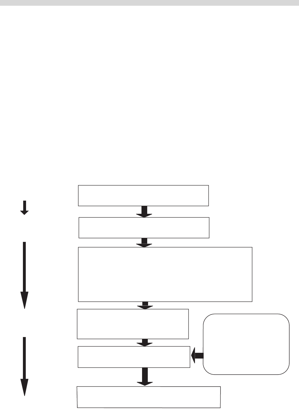
IGNITION SEQUENCE
First Stage – Trial For Pilot Ignition
On every call for heat (system start), the S86 performs an
internal safe-start check and shows that a ame-simulating
condition is present. During a normal start, the S86 opens the
pilot valve in the gas control. This allows gas to ow to the
pilot burner. Simultaneously the electronic spark generator
in the S86 produces a 30,000 volt pulse output. This voltage
produces a spark at the pilot burner igniter/sensor rod,
igniting the gas ow around the electrode. If the pilot ame
is not detected during the trial for pilot ignition, the S86H
contains a safety lockout timer (90 Seconds) to limit the
ignition period.
Second Stage – Main Burner Operation
When the Pilot ame is established, a ame rectication
circuit is complete to the burner ground. The S86 ame
sensing circuit detects the ame circuit and shuts the spark
generator o. At the same time the second operator (main
gas valve) is opened in the gas control, allowing gas ow
to the burners. This pilot ame ignites the main burner
conventionally.
Safety Lock Out Time.
The safety lockout timer circuit starts timing the moment the
trail for the pilot ignition starts. When the timing periods runs
out, the trial for ignition ends, and the control module goes
into lockout. Before another attempt to start can be made,
the S86 must be reset. Reset by adjusting the thermostat or
controller below room temperature, or to its "OFF" position.
An alternate method is to shut the system power "OFF". If
normal ignition does not occur, use the trouble shooting
table to determine the problem.
START
STAGE 1
TRIAL FOR
IGNITION
STAGE 2
MAIN BURNER
OPERATION
END
1. CONTROLLER CALLS FOR HEAT
2. SPARK GENERATOR POWERED
First valve (Pilot) operator opens
3. PILOT BURNER OPERATION
Pilot burner lights.
Module senses
ame current.
OR Pilot burner does not light.
After 90 seconds system
locks out: must be
manually reset.
4. FLAME CURRENT SENSED
• Spark generator o.
• Second valve operation (main) opens
POWER INTERRUPTION
System shuts o, restarts
when power is restored
PILOT FLAME FAILURE
Main valve closed.
Module start trail for ignition.
5. MAIN BURNER OPERATION
Module monitors pilot ame current
6. CONTROLLER SATISFIED
Valves close, pilot and main burners are o
Part # MCOSM06 Rev 1 (11/03/08) Page 29
NO
NO
NO
NO
NO
NO
NO
NO
START
YES
YES
YES
YES
YES
YES
YES
YES
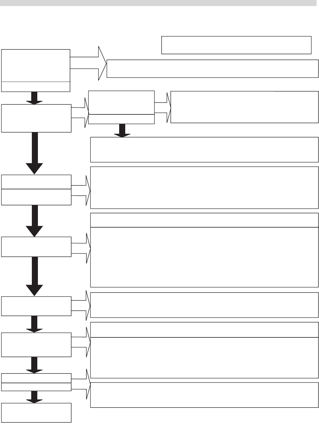
Note: Before trouble shooting familiarize yourself with
the startup procedure.
TURN GAS SUPPLY OFF.
TURN CONTROLLER TO
CALL FOR HEAT POWER
TO MODULE
(24V NOMINAL)
SPARK ACROSS IGNITER/
SENSOR GAP
TURN GAS SUPPLY ON
PILOT BURNER LIGHTS?
SPARK STOPS WHEN
PILOT IS LIT?
MAIN BURNER LIGHTS?
SYSTEM RUNS UNTIL
CALL FOR HEAT LOSS?
TROUBLE SHOOTING
ENDS
CALL FOR HEAT ENDS
SYSTEM SHUTS OFF?
Check line voltage power, low voltage transformer, limit controlled and wiring.
• Checkignitioncable,groundwire,ceramicinsulatorandgapandcorrect.
• Checkbootoftheignitioncableforsignsofmeltingorbuckling.Takeprotectiveactiontoshield
cable and boot from excess temperature.
•Onmodelswithventdamperplug,makesureventdamper
had not be installed, the remove. Replace vent damper if
necessary.
•Onothermodels,replacemodule
Pull ignition lead
and check spark and
module.
Spark okay?
• Checkthatallmanualgasvalvesareopen,supplytubingandpressurearegood,andpilotburner
orice is not blocked.
• Checkelectricconnectionsbetweenmoduleandpilotoperatorongascontrol.
• Checkfor24VACacrossPV-MV/PVterminalsonmodule.Ifvoltageisokay,replacegascontrol;if
not, replace module.
Note: If S5800B, H; S6810B, H goes into lockout, reset system. For S6800M, wait 6 minutes nominal
for retry or reset system
• Checkcontinuityofignitioncabletogroundwire.
• Cleanamerod.
• Checkelectricalconnectionbetweenamerodandmodule.
• Checkforcrackedceramicamerodinsulator.
• Checkthatthepilotamecoverstheroadandissteadyandblue.
• Adjustpilotame.
• Ifproblempersists,replacemodule.
Note: If S8600B, H; S6810B, H goes into lockout, reset system. For S6800M, wait 6 minutes, nominally
for retry or reset system.
• Checkcontinuityofignitioncableandgroundwire.
Note. If ground is poor or erratic, shutdowns may occur occasionally even though operation is
normal at the time of checkout.
• Checkthatthepilotamecoversamerodandissteadyandblue.
• Ifchecksareokay,replacethemodule.
• Checkfor24VACacrossMV-MV\PVterminals.Ifnovoltage,replacemodule.
• Checkelectricalconnectionsbetweenmoduleandgascontrol.Ifokay,replacegascontrolorgas
control operator.
• Checkforpropercontrolleroperation
• RemoveMVleadatmodule;ifvalvecloses,recheckthetemperaturecontrollerandwiring;ifnot,
replace gas control.
Repeat procedure until trouble free operation is obtained.
TROUBLE SHOOTING TABLE

Page 30 Part # MCOSM06 Rev 1 (11/03/08)
SERVICE
Preliminary Check
The following visual checks should be made before trouble
shooting and after installation or maintenance.
1. Check power to the appliance and S86.
2. Manual shuto cocks in the gas line must be open.
3. Make certain all wiring connections are clean and tight.
4. First de-energize the system and wait at least one (1)
minute. This resets the module allowing a return to the
start condition.
5. Review the S86 system normal sequence of operation.
System Trouble Shooting
Start the system by setting the controller above the required
temperature. Observe the system response. Establish the type
of malfunction or deviation from the normal operation. Use
the S286 Intermittent Pilot system trouble shooting table to
check for normal system operation.
Use the table by following the instruction questions in the
box. If the conditions is true or okay (answers yes), go down
to the next box underneath. If the condition is not true of
not okay (answer no), go right to the next box alongside.
Continue checking and answering conditions in each box
encountered, until a problem and/or the repair is explained.
After any maintenance or repair, the trouble shooting
sequence should be repeated until the trouble shooting
procedure ends with a normal system operation.
Check Grounding
A common ground is required for the pilot burner, the
igniter-sensor, the GND terminal of the S86, and the main
burner. The main burner generally serves as the common
ground. If the ground it poor or erratic, safety shutdowns may
occur occasionally even though operation is normal at time
of check out. Therefore, if nuisance shutdowns have been
reported, be sure to check the grounding.
Note: If the ground circuit path is incomplete, the S86H
system control will allow one trial for ignition before going
into safety lock out.
Electric grounding connections at the pilot burner,
igniter/sensor and S86 must be clean and tight. If a lead
wire is damaged or deteriorated, use only No. 14 or 18
gauge moisture resistant thermoplastic insulated wire
with 105°C (221°F) minimum ratings as replacement.
Excessive temperature at the ceramic ame rod can also
permit electrical leak to ground. Examine the ame rod and
mounting bracket, and correct if bent out of position. Replace
igniter/sensor if insulator is cracked.
Check Spark Ignition Circuit
The electronic module and step-up transformer in the S86
provides a spark ignition at 30,000 volts (open circuit). This
circuit can be checked at the S86 module as follows:
1. Turn o the manual gas cock to prevent the ow of gas.
2. Disconnect the ignition cable at the S86 stud terminal to
isolate the circuit from the pilot burner/igniter/sensor, and
prepare a shot jumper lead using heavily insulated wire,
such as ignition cable.
3. Energize the S86 touch one of the jumper rmly to the S86
ground terminal (GND). Do not disconnect the existing
ground lead. Move the free end slowly toward the stud
terminal to establish a spark and then pull the lead wire
slowly away from the stud. Not the length of the gap at
which the arching stops.
CAUTION: Do not touch either the stripped end of the jumper
or stud terminal. This is a very high voltage circuit and
electrical shock can result. Perform the test immediately upon
energizing the system – before the S86H goes into safety lock
out and interrupts the spark circuit.
4. An arch length of 1/8" (3.2mm) or more indicates a
satisfactory voltage output. Replace the S86 if not arc
can be established or the maximum gap is less then 1/8"
(3.2mm), and the fuse and power to the S86 input terminal
was okay.
Part # MCOSM06 Rev 1 (11/03/08) Page 31
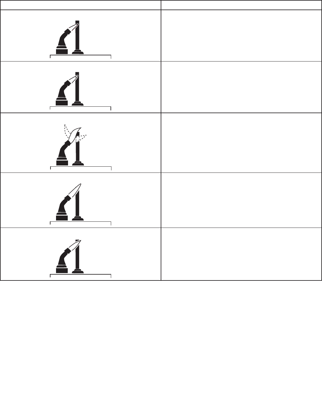
Examples Of Unsatisfactory Pilot Flames.
APPEARANCE CAUSE
SMALL BLUE FLAME Check for lack of gas from:
•Cloggedoricelter
•Cloggedpilotlter
•Lowgassupplypressure
•Pilotadjustedattheminimum
LAZY YELLOW FLAME Check for lack of air from:
•Largeorice
•Dirtylintscreen,ifused
•Dirtyprimaryairopening,ifthereisone
•Pilotadjustedatminimum
WAVING BLUE FLAME
Check for:
•Excessivedraftatpilotlocations
•Recirculatingproductsofcombustion
NOISY LIFTING BLOWING FLAME
Check for:
•Highgaspressure
HARD SHARP FLAME
This ame is characteristic of manufactured gas
Check for:
•Highgaspressure
•Oricetoosmall
Control Module Flame Sensor Circuit.
The control module provides AC power to theigniter/sensor
that the pilot burner ame recties to a direct current. If the
ame signal back the control module is not at least 1.0 μA
DC, the system will lockout. The output of the ame sensing
circuit cannot be checked directly, so check the ame sensing
circuit indirectly by checking the ame sensing current from
the igniter/sensor to the control module as follows:
1. Connect a meter (DC micrometer scale) in a series with
the ame signal ground wire (Burner Ground Terminal).
Disconnect the ground wire at the control module. Connect
the red (positive) lead of the meter to the free end of the
ground wire. Connect the black (negative) meter lead to the
quick-connect ground terminal on the control module.
2. Restart the system and read the meter. The ame sensor
currant must be at least 1.0 μA, and the reading must be
steady. If the reading is below the value designated or the
reading is unsteady, check the pilot ame and electrical
connection. Also, replace the igniter/sensor if the ceramic
insulator is cracked.
Page 32 Part # MCOSM06 Rev 1 (11/03/08)
G77x INTERMITTENT PILOT CONTROLS
Application Requirements
The following are the application requirements of the G77x
control.
• TheG77xcanbeusedongas-redequipmentwitha
maximum ring rate of 117kW (400,000 BTU/Hr). Any
application over 117kW (40,000 BTU/Hr) must have written
approval in advance from the Johnson Controls Heating
Products Engineering Department.
• AllG77xapplicationsmustusearedundantgasvalve
system where the pilot and main valve seats are in series
and opened in sequence for intermittent pilot ignition.
Operating Mode Denitions
The following denitions describe operating conditions.
• Prepurge: Initial time delay between thermostat contact
closure and trial for ignition.
• Trial for Ignition: Period during which the pilot valve and
spark are activated, attempting to ignite gas at the pilot
burner. The control attempts to prove ame at the pilot
burner within the trial-for-ignition time.
• Run: Pilot and main gas valves remain energized and spark
is turned o after successful ignition.
• 100% Shuto: For controls with automatic recycle, pilot
gas did not ignite within the trial-for-ignition time. The
control de-energizes the spark circuit and pilot valve.
• Automatic Recycle: If shuto occurs, the control delays for
a specic recycle delay period before beginning another
trial for ignition (models with recycle only).
• Interpurge: Period between trials for ignition when both
the gas valve and spark are deactivated to allow unburned
gas to escape before the next trial. Interpurge occurs
between unsuccessful trials on a multi-trial control or after
a ameout (if the control has an interpurge).
• Ignition Lockout: Pilot gas did not ignite within the nal
trial-for-ignition time. Open thermostat contacts for 30
seconds, then close to restart the sequence of operation.
(Models with an optional LED will ash the LED to indicate
ignition lockout.)
• Flameout: Loss of proven ame.
• Hard Lockout: The control detected a fault. Open
thermostat contacts for 30 seconds, then close to restart
the sequence of operation. (Models with an optional LED
will turn o the LED to indicate a hard lockout.)
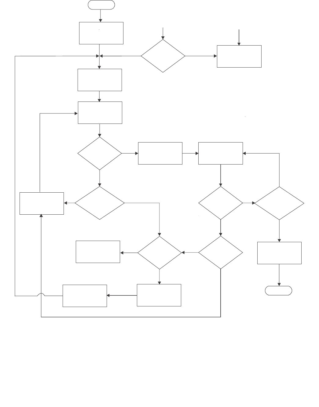
Sequence of Operation
Figure 2 illustrates the sequence of operation of the G77x
control.
The control is energized on a call for heat from the system
thermostat. (Models with an optional LED will turn on the
LED [steady on] until the call for heat is satised.) The vent
damper, if used, is energized and when fully opened, also
energizes the ignition control. If the control is equipped with
the optional prepurge, the appliance prepurge fan or relay
is also energized through the thermostat contacts. In the
prepurge mode, the control will delay for the time selected
(e.g., 15 seconds) before simultaneously opening the pilot
valve and supplying a continual spark at the pilot burner. If
prepurge is not selected, the pilot valve is opened and spark
initiated within one second after the call for heat.
Under normal conditions, the pilot burner gas ignites within
the trial-for-ignition time (e.g., 8 seconds), the pilot ame
sensor detects pilot ame and signals the control to energize
the main valve. The main gas valve will not be energized until
the ame sensor detects the presence of pilot ame. The
spark will continue until ame is sensed at the pilot burner or
the trial-for-ignition time has elapsed, whichever occurs rst.
If the pilot ame is not sensed before the end of the trial-for-
ignition time, the control may:
• proceedtointerpurge,followedbyanothertrial(three
trial models whose rst two trials produced no ame).
• proceedtoalockout(noautomaticrecyclemodelswhose
nal trial produced no ame).
• proceedtoarecycledelayperiodfollowedbyanothertrial
(automatic recycle models whose nal trial produced no
ame).
Part # MCOSM06 Rev 1 (11/03/08) Page 33
Figure 2
No Yes
Yes
No Maximum
number of trials
attempted?
Yes
No
YesNo
Yes
No
Yes
De-energize
control and valves
No
Sixteenth
ameout?
Control with
ignition
recycle?
Ignition lockout
(optional LED
ashes)
Yes
No
Recycle delay
period Shuto
Flame present when
not expected
Hard Lockout
(optional LED
turns o)
Start
Thermostat
call forheat
Prepurge
Flame
present for
30 seconds?
Detected fault
Trial for
ignition
Pilot
ame
sensed?
Energize
main valveRun
Thermostat
calling for heat?
Flameout?
Interpurge
End
Page 34 Part # MCOSM06 Rev 1 (11/03/08)
If the pilot burner ame extinguishes during the run state
(ameout), the control de-energizes the pilot and main gas
valve for the interpurge period. After this period, another
trial for ignition is initiated. If the ameout cycle repeats for a
total of 16 times (pilot burner ame established then lost), the
control will:
• EnterthelockoutmodeifthecontrolisaG770/G777.The
thermostat contacts must be opened for 30 seconds and
then closed to escape the lockout condition.
• Entertheshutomodeandrecycleperiod(5minute
recycle delay for the G775/G779 and 60 minute recycle
for the G776/G778) before beginning another trial for
ignition, starting with prepurge.
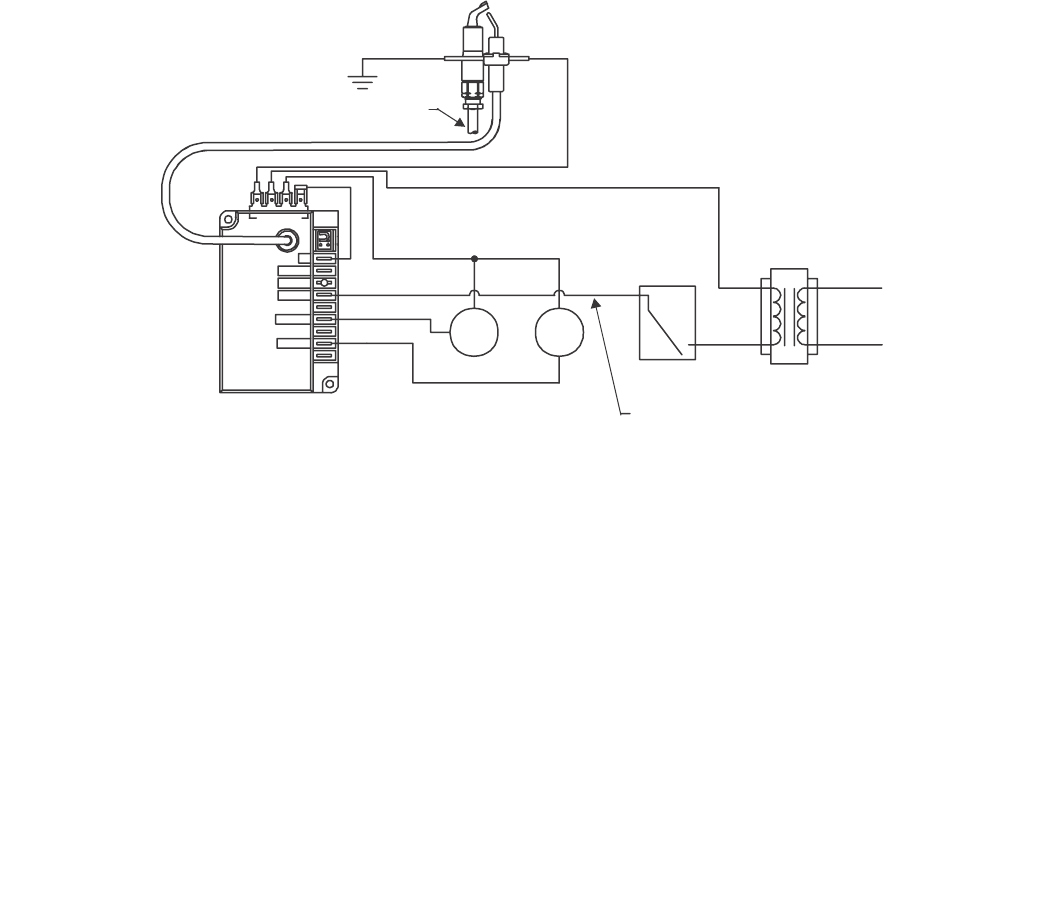
Wiring Diagram For Integral Spark/Sense Without Vent Damper
GROUND
5
24 V
LED
THS 2
PV 1
MV 3
Transformer
Pilot Burner
Assembly Integral
Igniter/Sensor
Main Burner
Ground
Pilot
Gas Supply
Pilot
Valve
Main
Valve
Ignition ControlLimits in Thermostat
Line Only
Part # MCOSM06 Rev 1 (11/03/08) Page 35
G76X DIRECT SPARK IGNITION CONTROLS
Application Requirements
Following are the application requirements of the
G76xcontrol.
• TheG76xcanbeusedongas-redequipmentwitha
maximum ring rate of 117 kW (400,000 Btu/hr). Any
application greater than117 kW (400,000 Btu/hr) must
have written approval in advance from the Johnson
Controls Heating Products Engineering Department.
• AllG76xapplicationsmustusearedundantgasvalve
system where the main valve seats are in series and open
simultaneous for direct spark burner ignition.
Operating Mode Denitions
The following denitions describe operating conditions:
• Prepurge: Initial time delay between thermostat contact
closure and trial for ignition.
• Trial for Ignition: Period during which the main valve and
spark are energized in an attempt to ignite gas at the main
burner. The control attempts to prove ame at the main
burner within the trial-for-ignition time.
• Run: Main gas valve remains energized and the spark is
turned o after successful ignition.
• 100% Shuto: For controls with automatic recycle, main
gas did not ignite within the trial-for-ignition time. The
control de-energizes the spark circuit and main valve.
• Automatic Recycle: If 100% shuto occurs, the control
delays for a specic recycle delay period before beginning
another trial for ignition. (Modelswith recycle only.)
• Interpurge: Period between trials for ignition when both
the gas valve and spark are deactivated to allow unburned
gas to escape before the next trial. Interpurge occurs
between unsuccessful trials on a multi-trial control or after
a loss of proven ame (ameout).
• Ignition Lockout: Main gas did not ignite within the nal
trial-for-ignition time. Open the thermostat contacts for 30
seconds, then close to restart the sequence of operation.
(Models with an optional LED will ash the LED to indicate
ignition lockout.)
• Flameout: Loss of proven ame.
• Hard Lockout: The control detected a fault. Open the
thermostat contacts for 30 seconds, then close to restart
the sequence of operation. (Models with an optional LED
will turn o the LED to indicate a hard lockout.)
Sequence Of Operation
Figure 3 illustrates the sequence of operation of the G76x
control.
The control is energized on a call for heat from the system
thermostat. (Models with an optional LED will turn on the LED
[steady on] until the call for heat is satised.) If the control is
equipped with the optional prepurge, the control will delay
for the time selected before initiating a trial for ignition.
During the trial for ignition, the control attempts to light the
main burner by simultaneously energizing the main gas valve
and supplying a continuous spark at the igniter electrode.
If the optional prepurge is not selected, then the trial for
ignition begins within one second after the call for heat.
The spark is deactivated immediately following the trial for
ignition.
Under normal conditions, the main burner gas ignites within
the trial-for-ignition time. If the control senses main burner
ame by the end of the trial, the control proceeds to a run
condition. During the run state, the control energizes the
main valve until the call for heat ends, or until a ameout
occurs. If main burner ame is not sensed by the end of the
trial-for-ignition time, the control may:
• Proceedtoa30-secondinterpurgefollowedbyanother
trial (three trial models whose rst two trials produced no
ame)
• Proceedtoalockout(noautomaticrecyclemodelswhose
nal trial produced no ame)
• Proceedtoarecycledelayperiodfollowedbyanothertrial
(automatic recycle models whose nal trial produced no
ame)
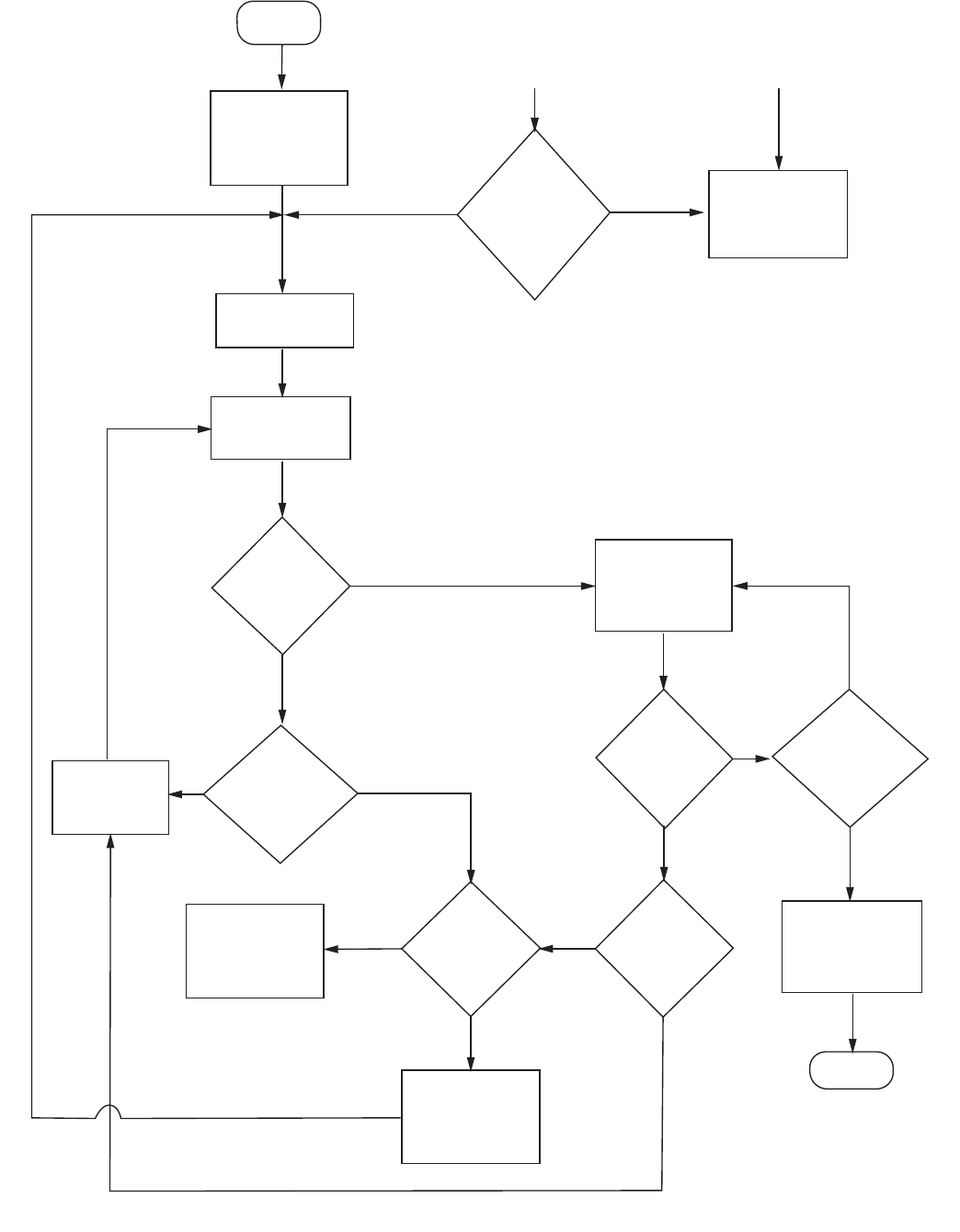
Page 36 Part # MCOSM06 Rev 1 (11/03/08)
Fig 3 Sequence of Operation
Start
Thermostat
call for heat
Prepurge
Trial for
ignition
Main valve
ame sensed?
Yes
No
Interpurge
Maximum
number of trials
attempted?
No Yes
Ignition lookout
(optinal LED
ashes)
No Control
with ignition
recycle?
Yes
Yes
Recycle delay
period
Flame present when
not expected
No Yes
Flame
present for
30 seconds?
Detected fault
Hard Lockout
(optional LED
turns o)
Run
Flameout?
Yes
Sixteenth
ameout?
No
No
Yes
Thermostat
callin for heat?
No
De-energize
control and valves
End
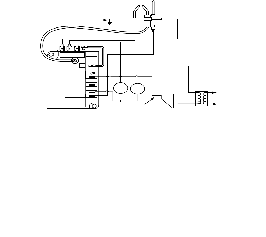
Part # MCOSM06 Rev 1 (11/03/08) Page 37
If the main burner ame extinguishes during the run state,
the control de-energizes the main gas valve for an interpurge
of 30 seconds. After this period, another trial for ignition is
initiated. If this ameout cycle repeats for a total of 16 times
(main burner ame established, then lost), the control will:
• EnterthelockoutmodeifthecontrolisaG760.The
thermostat contacts must be opened for 30 seconds and
then closed to escape the lockout condition.
• Enterthe100%shutomodeandrecycleperiod(5
minute recycle delay for the G765 and 60 minute recycle
delay for the G766) before beginning another trial for
ignition, starting with prepurge.
Wiring Diagram for G76x Ignniton Control
Main Burner
Ground
Spark Electrode/
Sensor Assembly
G76x Ignition Control
Limits In
Thermostat
Line Only Thermostat Transformer
Power
Supply
MAIN
VALVE
MAIN
VALVE
GROUND
5
LED
THS 2
M.V. 3
SENSE 4

Page 38 Part # MCOSM06 Rev 1 (11/03/08)

Part # MCOSM06 Rev 1 (11/03/08) Page 39
Section Three
Temperature
Calibration
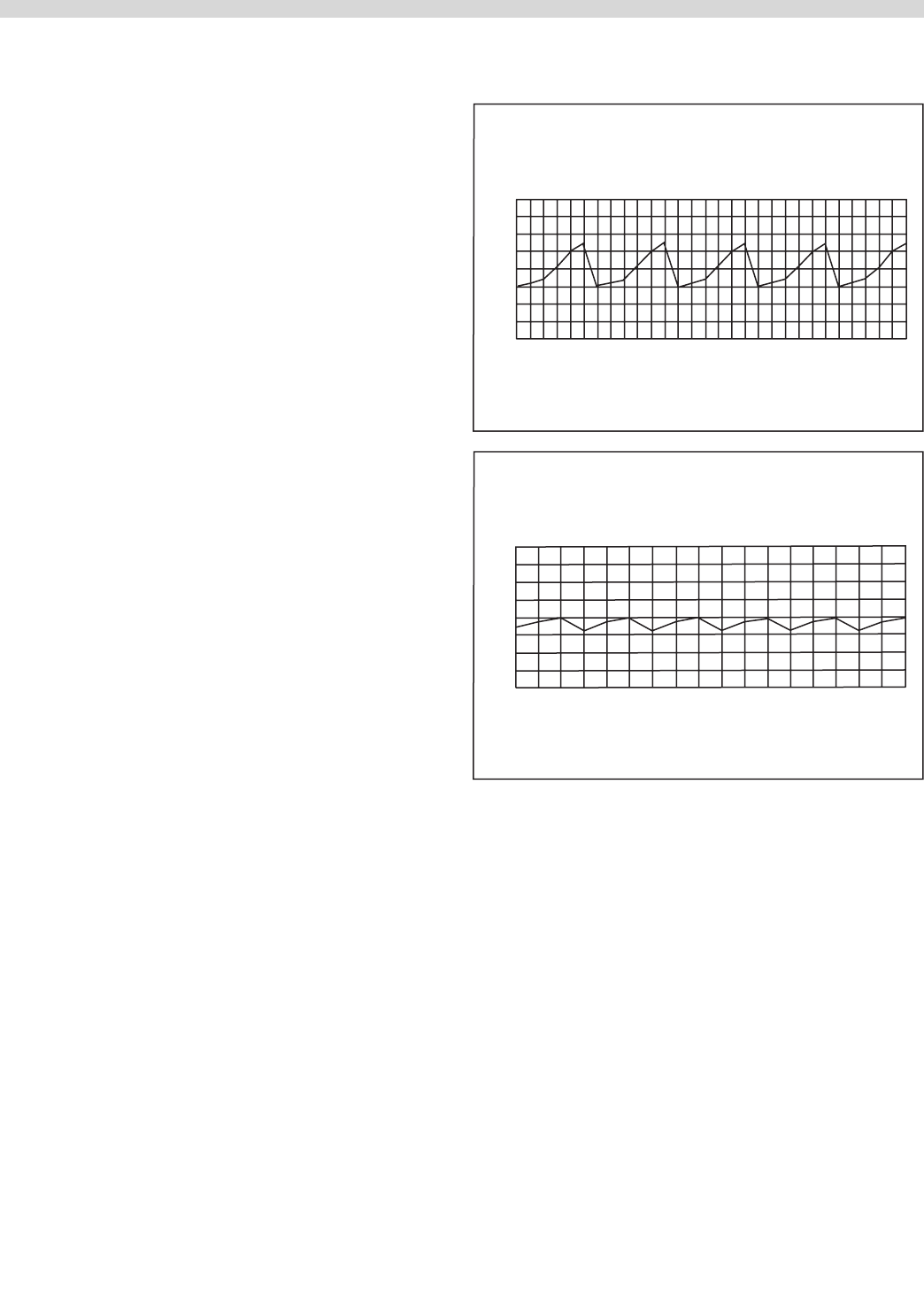
Page 40 Part # MCOSM06 Rev 1 (11/03/08)
GENERAL CALIBRATION
Instrumentation
A thermocouple type test instrument is preferred for
measuring oven temperatures accurately. Mercury
thermometers are acceptable providing they can be proven
accurate.
Regardless of the type instrument used, it is most desirable
to double-check it just before making an oven temperature
check. This can be done simply and quickly by placing
the thermocouple tip (or immersing the entire mercury
thermometer) in boiling water. Note: Mercury oven
thermometers should be the "Total immersion type." The
resulting reading should be within several degrees of 212°F,
depending on the altitude.
Generally, a mercury thermometer can drop and excess of
25° F when the doors are opened to check oven temperature.
This condition makes it extremely dicult to get a true
temperature reading.
Almost all convection ovens today have oven burners which
cycle "on and o" The high and low points of the resulting
temperature "swing" (dierential) in the oven must be
measured- and averaged-to determine the true operating
temperature. A thermocouple type test instrument is best
suited to measure these temperature changes quickly and
accurately, and without opening the oven door.
With an accurate, thermocouple test instrument or mercury
thermometer, it is still dicult to measure these changing
oven temperatures and then, average correctly. This is why
we recommend that the thermocouple tip or the bulb of the
thermometer be "weighed" Weighing (adding mass) to the
test instrument compensates for oven temperature changes
making the test instrument less sensitive to these constant
changes in temperature. Note: How this weighting can be
done is discussed later.
Measuring these changing high and low temperature points
in an oven is possible with either type of test device with out
weighing, but is subject to possible inaccuracies. This is most
true at a low temperature setting because, in this area, the
function of "time" becomes a factor. The simple averaging
of temperatures then may not produce the true operating
temperature. "Weighing" provides the compensation for both
time and temperature that is necessary. We produced test
curved showing actual results in the low temperature area
showing the dierence in results when using an unweighted
and weighted thermocouple or thermometer. Tests were
made with the same control, same oven and dial set at 170°
mark (not moved).
260
240
220
200
180
160
140
120
100
Chart No.1
Unweighted Thermocouple dial setting 170 F
260
240
220
200
180
160
140
120
100
Chart No.2
Weighted Thermocouple Dial Setting 170F
From the above, it can be seen that an error of 15°F is
possible. Chart #1, unweighted thermocouple indicates
an erroneous average oven temperature of 185°F, Chart
#2 weighted thermocouple indicates the "average" or true
temperature to be 170°F.
Weighing of Thermocouple
A thermocouple can be weighted by clamping the tip
between two one inch square 1/16" inch thick aluminum. The
thermocouple can also be weighted (just as successfully) by
using a letter sized sheet of aluminum foil. Fold the foil ve
times doubling the thickness each fold. After the fth fold,
place the thermocouple tip in the center of the aluminum
piece and fold once more. Finally fold in the sides so that the
foil clings to the thermocouple tip. A mercury thermometer
can be weighted in much the same way by wrapping several
layers of aluminum foil around the bulb end thus creating the
necessary mass. This procedure is a must if you open the door
to check the temperature.
Part # MCOSM06 Rev 1 (11/03/08) Page 41
Resistance Vs. Temperature Chart
For Internal Oven Temperature Sensor
The Chart below will provide the Ohms at various
temperatures. This will enable you to determine if the
temperature probe is operable.
The chart is in degrees Fahrenheit.
TEMP 0° 10° 20° 30° 40° 50° 60° 70° 80° 90°
0° 932 953 974 995 1016 1038 1059 1080 1101 1122
100° 1143 1163 1184 1205 1226 1247 1267 1288 1309 1329
200° 1350 1370 1391 1411 1432 1452 1472 1493 1513 1533
300° 1553 1574 1594 1614 1634 1654 1674 1694 1714 1733
400° 1753 1773 1793 1813 1832 1852 1871 1891 1911 1930
500° 1949 1969 1988 2008 2027 2046 2065 2085 2104 2123
200 & 300 SERIES CONTROLLERS CALIBRATION
Both the 200 & 300 series controllers use a 0 to 10.25k OHM
potentiometer. First check the sweep on the potentiometer
between the middle wire and one of the outside wires
for a gradual increase or decrease in the resistance as the
potentiometer stem is turned.
Gas Units – Calibration 300 Series
1. Remove the temperature dial from the potentiometer.
2. Turn the potentiometer to its lowest setting (fully counter
clock-wise).
3. Place the temperature dial back on the potentiometer.
4. Align the mark on the temperature dial to the top left
edge of the 'F': on the left of the temperature dial and
sung down one of the set screws. DO NOT fully tighten
yet.
5. Set the temperature dial to 150°F and allow the oven
cavity for reach set temperature.
6. Conrm the temperature inside the oven cavity with you
meter and that shown on the temperature dial.
7. If an adjustment is required, loosen the set screw
and position the mark on the temperature dial to the
temperature shown on your meter.
8. Tighten set screw down.
9. Repeat as required (once is usually enough).
10. Fully tighten both set screws.
Gas Units – Calibration 200 Series
1. Remove the temperature dial from the potentiometer.
2. Turn the potentiometer to its highest setting (fully clock-
wise).
3. Place the temperature dial back onto the potentiometer.
4. Align the mark on the temperature dial 1/4" PAST the
500°F marking on the overlay and snug down one of the
set screws. Do NOT fully tighten yet.
5. Set the temperature dial to 159°F and allow the oven
cavity to reach set temperature.

Page 42 Part # MCOSM06 Rev 1 (11/03/08)
6. Conrm the temperature inside the oven cavity with your
meter and that shown on the temperature dial.
7. If an adjustment is required, loosen the set screw
and position the mark on the temperature dial to the
temperature shown on your meter.
8. Tighten set screw down.
9. Repeat as required (once is usually enough).
10. Fully tighten both set screws.
Electric Units – Calibration 300 Series
1. Remove the temperature dial from the potentiometer.
2. Turn the potentiometer to its lowest setting (fully counter
clock-wise).
3. Place the temperature dial back on the potentiometer.
4. Align the mark on the temperature dial to the top left
edge of the "F": on the left of the temperature dial and
sung down one of the set screws. Do Not fully tighten yet.
5. Set the temperature to 300°F and allow the unit to cycle 3
times.
6 Conrm the temperature inside the oven cavity with your
meter and that on the temperature dial.
7. If adjustment is required, loosen the set screw and
position the mark on the temperature dial to the
temperature shown on your meter.
8. Tighten set screw down.
9. Repeat as required (once is usually enough).
10. Fully tighten both set screws.
Electric Units – 200 series
1. Remove the temperature dial from the potentiometer.
2. Turn the potentiometer to its highest setting (fully clock
wise).
3. Place the temperature dial back on the potentiometer.
4. Align the mark on the temperature dial 1/4" PAST the
500°F marking on the overlay and snug down one of the
set screws. Do NOT fully tighten yet.
5. Set the temperature to 300°F and allow to cycle 3-times.
6. Conrm the temperature inside the oven cavity with your
meter and that on the temperature dial.
7. If adjustment is required, loosen the set screw and
position the mark on the temperature dial to the
temperature shown on your meter.
8. Tighten set screw down.
9. Repeat as required (once is usually enough).
10. Fully tighten both set screws.

Part # MCOSM06 Rev 1 (11/03/08) Page 43
Section Four
Convection Oven
Components
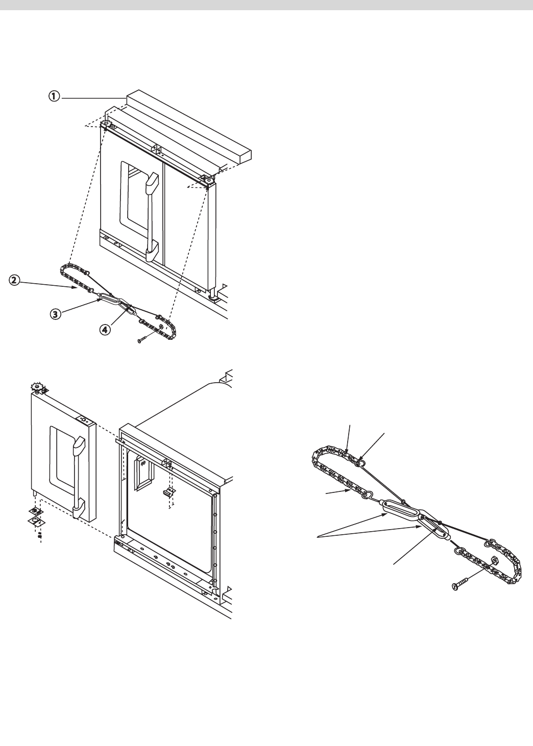
Page 44 Part # MCOSM06 Rev 1 (11/03/08)
DOORS
To Remove Doors From Oven
1
2
3
4
1. Remove top front cap veneer.
2 Remove door change assembly (Note: The "A" model does
not come equipped with door chain).
3. Remove at head metal screw 1/4"-2-x1/2" from bearing
retainer.
4. Push the door toward the hinge and lift up. NOTE: The
bottom bearing retainer will stay in place.
5. Remove the right door in the same manner.
To Reinstall Doors onto Convection Oven
1. Reverse procedure above.
2. Close doors.
3. Reinstall the door chain.
Installing and Adjusting Door Chain
1. Make sure two links are between sprocket and door rod,
and there should be 8 regular links plus one master link on
the forward side of each chain.
2. Tighten up the buckles, the right door should close
approximately 1/2" before the left door.
3. Secure the turnbuckles by tightening the lock nuts.
T
urnbuckles
Locking Nuts
Door Stop Bolt
2 Links
8 Links
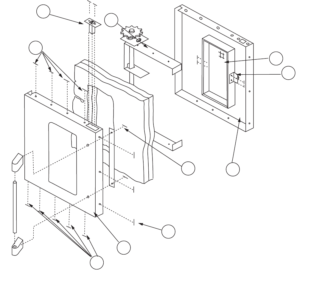
Part # MCOSM06 Rev 1 (11/03/08) Page 45
Disassembly Of The Left Door
1. Once the door has been removed from the oven (refer to
previous instructions), remove the 12 truss head 10 x 1/2
Phillips screws.
2. Remove 2 allen head cop screws from the door handle.
3. Carefully pry o the door panel from the door window
bezel.
4. Remove 2 hex head m.s. 1/4-20x1/2 from the door liner
that attach hold down straps to the door liner.
5. Lift out the door frame.
6. Carefully pry o the door window for the door liner.
7. To remove the door catch remove 2 pan head Phillips
screws.
8. To reassemble – reverse the above procedure.
NOTE: There is a seam on one side of the bezel that is part of
the door window, reinstall working from the opposite side
of that the seam is on and work around the window towards
that seam.
1
7
7
7
6
3
4
5
2
8
NOTICE: DEPENDENT DOOR SHOWN
Disassembly of the Left Door
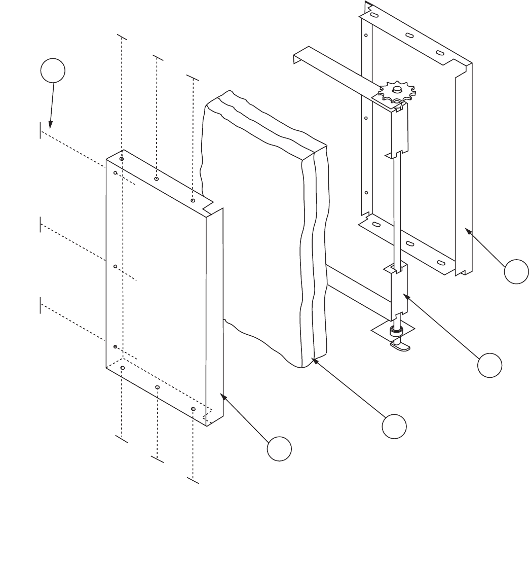
Page 46 Part # MCOSM06 Rev 1 (11/03/08)
Disassembly of the Right Door (w/o window)
1. Once the door has been removed from the oven (See
previous section), remove 9 truss head s.m.s. 10 x 1/2 from
the top, bottom and left side (as shown) from the door
panel.
2. Pry the door liner apart from the door panel. This will
expose the door frame.
3. To reassemble, reverse the above procedure.
4
3
2
1
5
Disassembly of the Right Door (w/o window)
NOTICE; DEPENDENT RIGHT HAND DOOR SHOWN.
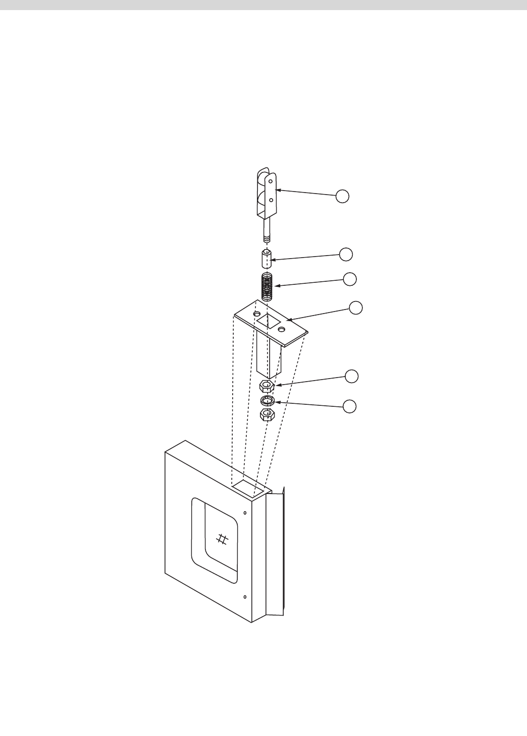
Part # MCOSM06 Rev 1 (11/03/08) Page 47
To Replace Or Adjust
The Door Latch Mechanism
1. Open the oven doors.
2. Remove 2 pan head Phillips screws.
DOOR LATCH MECHANISM
5
4
2
6
3
1
3. Lift door latch mechanism up and out of the door
assembly.
4. To adjust the latch mechanism, loosen lock nut & adjust by
tightening or loosening the adjustment nut.
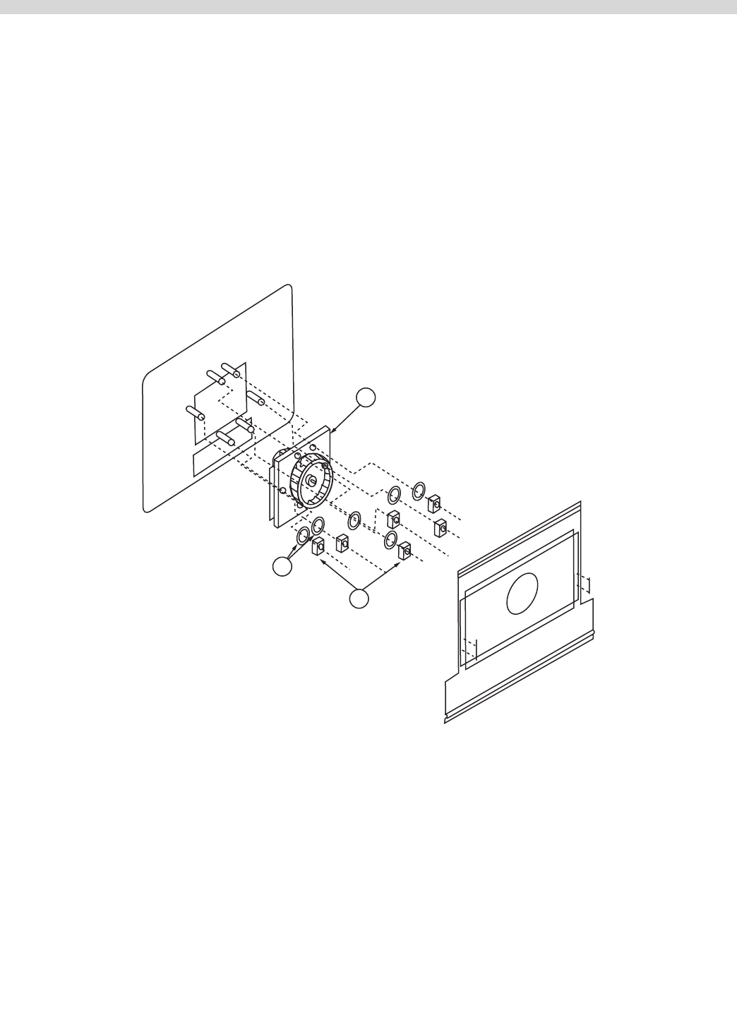
Page 48 Part # MCOSM06 Rev 1 (11/03/08)
MOTOR
To Replace Convection Oven
Motor Assembly
1. Open doors and remove all oven racks.
2. Remove 4 #10 sheet metal screws (that secure the air
bae) and remove air bae.
3. Remove six hex nut 1/4-20x7/16" (2A) and lock washers
(4A) from the motor mounting studs.
4. Place a piece of cardboard on the oven oor to protect
from scratching or chipping.
5. Pull the entire motor assembly (1A) away from the rear
oven wall into the oven cavity and place on cardboard.
6. Disconnect wiring, be sure to note wire locations.
7. To reinstall reverse the above procedure.
1A
4A
2A
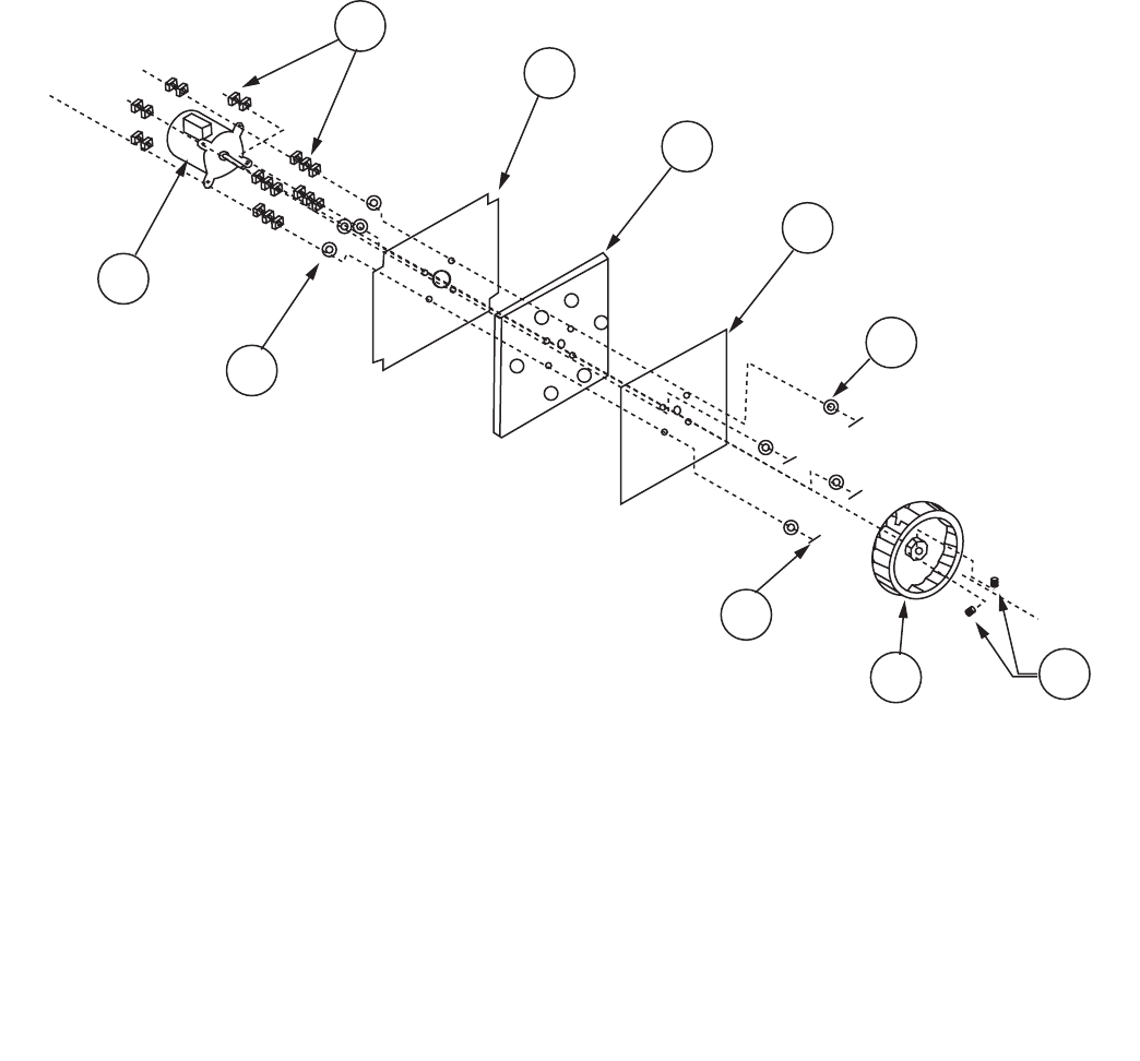
Part # MCOSM06 Rev 1 (11/03/08) Page 49
Convection Oven Motor Assembly
1. Assemble the motor mount plate, insulation, and motor
mount plate inner together by fastening four at head
m.s. 1/4-20x21/2" into the four holes noted on the above
drawing.
2. Secure each at head m/s/ 1/4-20x21/2" with a at washer
and three hex nuts 1/4-20.
3. Attach the motor mounting plate to the motor. Insert the
four at head m.s. 1/4-20x21/2" though the mounting tabs
on the motor as shown. Secure with two hex nuts 1/4-20.
4. Insert the shaft of the motor though the hub of the blower
wheel. Space the wheel 1/4" away from the inner motor
mounting plate.
5. Secure the blower wheel to the shaft of the motor by
tightening the two set screws on the blower wheel hub.
Use a torque wrench and tighten to 180 inch pounds for
proper securing.
6
2
1
3
5
9
8
4
5
7
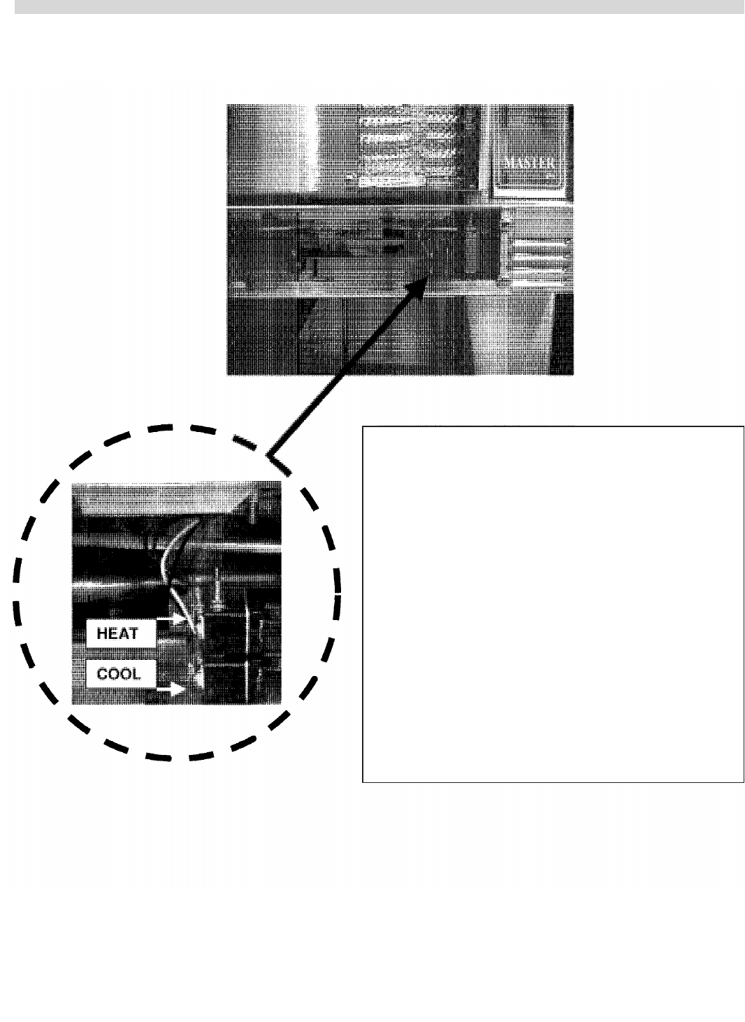
Page 50 Part # MCOSM06 Rev 1 (11/03/08)
DOOR MICROSWITCH
Upper micro switch "Heat"
•BROWNwiregoesfromnormallyopendoorswitch
to terminal T3 on the relay board.
•BLUEwiregoesfromthecommononthedoorswitch
to terminal T4 on the relay board.
Lower micro switch "Cool"
•BLACKwiregoesfromnormallyopendoorswitchto
terminal T6 on the relay board.
•WHITEwiregoesfromcommononthedoorswitch
to terminal T5 on the relay board.
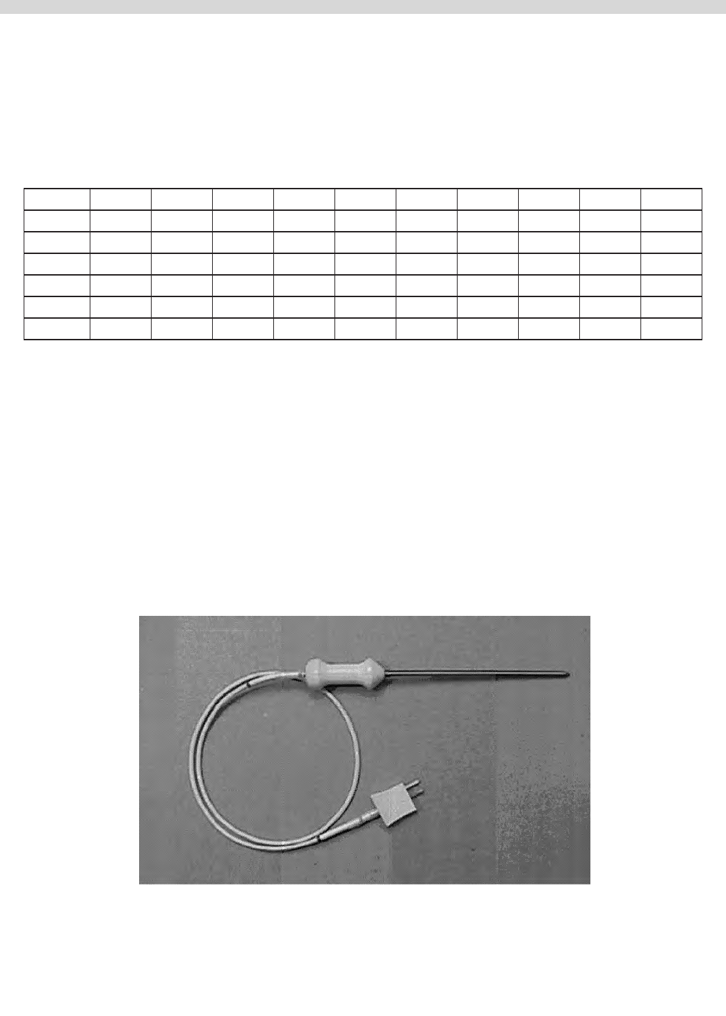
Part # MCOSM06 Rev 1 (11/03/08) Page 51
PROBES
Oven Cavity Probe
Resistance vs. Temperature Chart For Internal Oven Cavity
Temperature Sensor.
The chart below will provide the Ohms at various
temperatures. This will enable you to determine if the
temperature probe is operable.
The chart is degrees Fahrenheit.
TEMP 0° 10° 20° 30° 40° 50° 60° 70° 80° 90°
0° 932 953 974 995 1016 1038 1059 1080 1101 1122
100° 1143 1163 1184 1205 1226 1247 1267 1288 1309 1329
200° 1350 1370 1391 1411 1432 1452 1472 1493 1513 1533
300° 1553 1574 1594 1614 1634 1654 1674 1694 1714 1733
400° 1753 1773 1793 1813 1832 1852 1871 1891 1911 1930
500° 1949 1969 1988 2008 2027 2046 2065 2085 2104 2123
Resistance Readings
77°F =1000 ohms
100°F =1103 ohms
200°F =1350 ohms
300°F =1554 ohms
350°F =1654 ohms
400°F =1753 ohms
NOTE: If the cavity core probe is used, the core probe Led will
be lit on the control panel, the temperature of the product
will be displayed if the product is about 32°F.
The programmed range for the core probe is 100°F to 200°F.
Cavity Core Probe (455 Only)
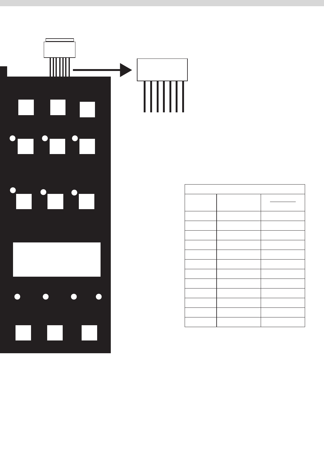
Page 52 Part # MCOSM06 Rev 1 (11/03/08)
KEY PAD TEST
Key
#9
Key
#5 Key
#1
Key
#10
Key
#6
Key
#2
Key
#12
Key
#8
Key
#4
Key
#11
Key
#7
Key
#3
DISPLAY
Ribbon
Connector PIN DETAIL
VIEWED FRON FRONT PIN NUMBERS
On Ribbon
Connector
7 6 5 4 3 2 1
KEYPAD & TEST
POINTS VIEWED
FRON FRONT
PIN- OUT TEST POINTS
Key # PIN-OUTS OVERLAY
MARKINGS
1 1 & 4 SET BACK
2 1 & 5 COOL DOWN
3 1 & 6 PROGRAM
4 1 & 7 ACTUAL TEMP
5 2 & 4 CAVITY LIGHT
6 2 & 5 FAN LOW
7 2 & 6 COOK / HOLD
8 2 & 7 SET
9 3 & 4 ON / OFF
10 3 & 5 FAN HIGH
11 3 & 6 PULSE
12 3 & 7 START/CANCEL
Between the above pin test points on the ribbon connector,
there should be continunty when the corresponding key is
pressed.
EXAMPLE: When Key # 1 is pressed and held, there should be
continunity between pins 1 & 4 at the ribbon cable.
NOTE: The keypad must be attached to the control panel
bezel when tested. The keypad is grounded to the panel to
complete the circuit. Disconnec the ribbon connector from
the SMART BOARD / CONTROLLER to gain better access to
teest points.
Not all overlays will have the above-indicated markings.
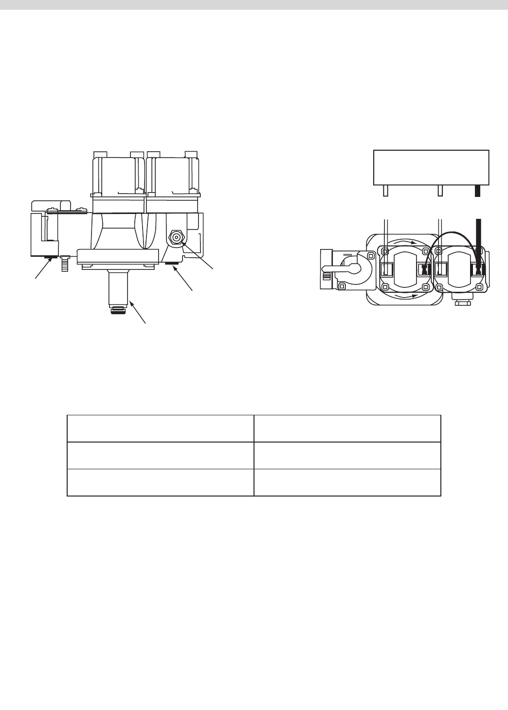
Part # MCOSM06 Rev 1 (11/03/08) Page 53
MCO CONVECTION OVEN GAS VALVE
SIDE VIEW TOP VIEW
PILOT
VALVE
MAIN
VALVE
Manual
'A' Valve
Inlet
Inlet
Pressure
Tap
Regulator
Outlet
Pressure
Tap
Pilot
Outlet
Outlet
Pilot Valve
Connection
Main Valve
Connection
Common
Connection
Intermittent Pilot
Ignition Control
Specications
Regulator Adjustment Range 3 to 6" WC natural gas
5 to 12" WC propane gas
Maximum Operating Pressure 14" WC both natural & propane gas
Minimum Incoming Pressure 7" WC natural gas
14" WC propane gas
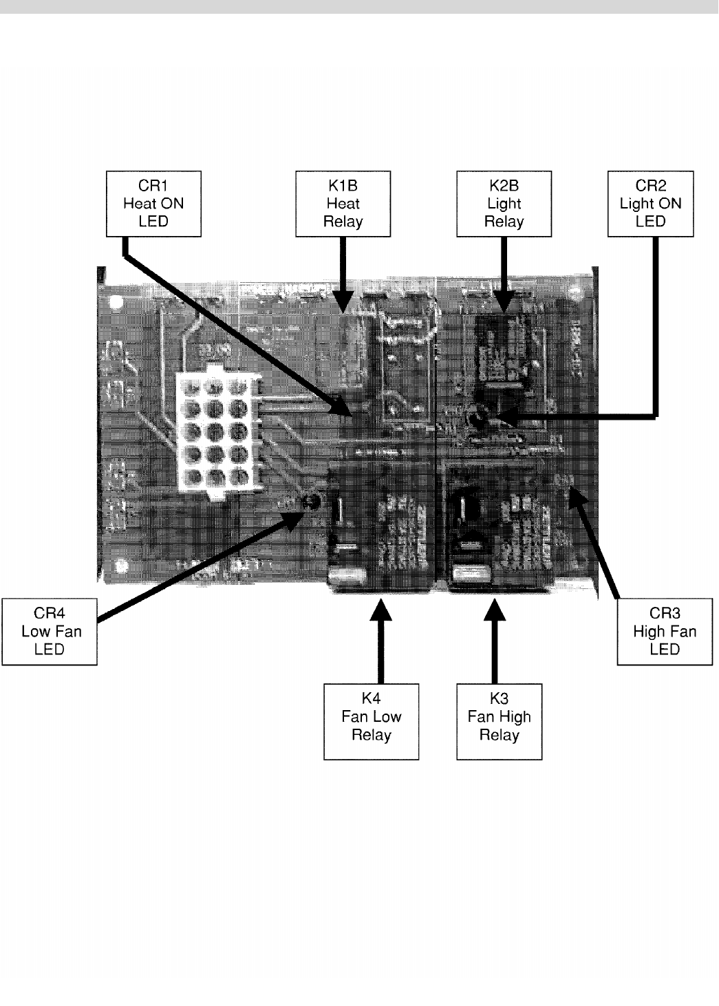
Page 54 Part # MCOSM06 Rev 1 (11/03/08)
RELAY BOARDS
Part # MCOSM06 Rev 1 (11/03/08) Page 55
Testing
Test Points at 15 Pin Molex Connection
Through the back side of the Molex Connection with both the controller and the Relay
board connected:
Power to Controller Pin 1 (white) & Pin 3 (white) 24 v.a.c. ±10%
Door Switch
SW1 for HEAT
(Upper Switch)
Pin 9 (black) & Pin 10 (white/gray) 5 v. a..c. ±10%
Door Switch SW2
for COOL
(Lower Switch)
Pin 9 (black) & Pin 12 (grey) 5 v. a..c. ±10%
The Next Pin Tests are Key Function Specic
(Criteria: You must activate the switch you are testing)
Fan High Pin 5 (red) & Pin 7 (orange/white) 24 v.a.c. ±10%
Fan Low Pin 5 (red) & Pin 8 (orange) 24 v.a.c. ±10%
Heat Demand Pin 5 (red) & Pen 4 (white/violet) 24 v.a.c. ±10%
Oven Light Pin 5 (red) & Pin 6 (violet) 24 v.a.c. ±10%
The Next tests are Ohm Readings
Criteria: You must disconnect the probes and test probes only.
Cavity probe open (oven) See RTD chart under Probes this section
Core Probe (meat) See chart under Probes, this section
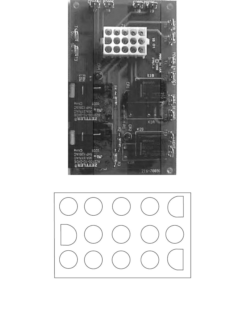
Page 56 Part # MCOSM06 Rev 1 (11/03/08)
Motor Relay Board
15 12 96
3
14 11 852
13 10 7 41

Part # MCOSM06 Rev 1 (11/03/08) Page 57
CONTROLS
Display Codes – Prompts
OFF Oven is in the OFF mode.
Lo Oven cavity temperature is below set point.
Hi Oven cavity temperature is above set point.
LOAd Oven cavity has reached set temperature - prompt for operator to load oven.
SETb Oven has defaulted to factory set back temperature.
Auto Oven is in 'auto cool down' mode and will remain in auto until cavity temp is below 150°F.
OPEn
Display will toggle from 'OPEN' to 'DOOR' to prompt for operator to open door when unit is in cool down.
Door
Door In auto cool down mode, door is open past 30° or in cooking mode, door is opened.
Prob Open or shorted cavity sensing probe.
HELP Oven cavity has exceeded 560°F.
CodE 475 controllers, prompt for operator to enter access code from programming 4-2-7-5.
SHLF 475 controllers, prompt for operator to select shelf to be programmed.
PR- 475 controllers, prompt for operator to program the prole for the second cook time if required.
PRE 475 controllers, prompt for operator to set pre-alarm if required.
HoLd 475 controllers, prompt for operator set the hold temperature the oven is in programmed HOLD
temperature.
FAn 475 controller, prompt for operator to se fan speed.
DonE Oven has completed its cooking cycle.
CooL Door is open less then 30° in cool down mode.

Page 58 Part # MCOSM06 Rev 1 (11/03/08)

Part # MCOSM06 Rev 1 (11/03/08) Page 59
Section Five
Trouble Shooting

Page 60 Part # MCOSM06 Rev 1 (11/03/08)
CONTROLLER OPERATIONAL TESTS
For the Garland (US Range) 200(20) – 300(30) – 410(41)
– 450(45) – 455(45+) – 470 – 4712 – 475 FAST convection oven
controls.
200 Series Controller (Thermostat only)
Turn the oven on, the oven should heat to set temperature
within 30 minutes. If the oven does not heat, ohm out the
probe, at room temperature the probe should read about
1,000 ohms. Ohm the probe at the faston connection. See
the chart for other resistance readings. If the probe reads
an open or short, replace the defective probe. Check the
probe interconnect harness to make sure the circuit is good,
connections etc.
The heat relay K1 should be energized when heating the oven
and opened if it is not calling for heat.
The fan is not controlled by the controller.
300 Series Controller
(Thermostat and relay board)
Turn the oven on, the oven should heat to set temperature
within 30 minutes. If the oven does not heat, ohm out the
probe, at room temperature the probe should read about
1,000 ohms. Ohm the probe at the faston connection. See
chart for other resistance readings. If the probe reads an
open or short replace the defective probe. Check the probe
interconnect harness to make sure the circuit is good,
connections, etc.
The heat demand rely K1B should be energized then heating
the oven and opened if it is not calling for heat. Look at the
heat LED CR1 on the relay board, the LED will be lit when the
controller calls for heat. Check the door switch if the heat
does not activate. Upper door switch is for HEAT.
The fan can switch from low to high speed. Look at the fan
LED on the relay board (there is a low CR4 and a high fan
CR30, the LED will be lit when the controller calls for either
fan. If the operator cannot switch from one fan speed to
another check the keypad. If the light switched on the display
from one fan speed to another but the fan did not change
speeds check the relay board. If the display switched and the
fan went o, check the fan itself.
If the keypad does not respond, check the keypad as outlined
in bulletin B-107-2001.
If the potentiometer does not adjust the temperature, check
the potentiometer. Pot is a 0 to 10.25K Ohm pot.
410 Series Controller
(Thermostat, display and relay board)
Turn the oven on, the oven should heat to set temperature
within 30 minutes. Press the temperature icon and the
temperature can be viewed above 100 degrees F. If the oven
does not heat, ohm out the probe, at room temperature the
probe should read about 1,000 ohms. Ohm the probe at the
faston connection. See chart under Probes in section four for
other resistance readings. If the probe reads an open or short
replace the defective probe.
The heat demand relay K1F should be energized when
heating the oven and opened if it is not calling for heat.
Look at the heat LED CR1 on the relay board, the LED will be
lit when the controller calls for heat. Check the upper door
switch if the heat does not activate.
The fan can switch from low to high speed. Look at the fan
LED on the relay board (CR3 LED for high and CR4 for low
speed), the LED will be lit when the controller calls for either
fan. If the operator cannot switch from one fan speed to
another, check the keypad. If the light switched on the display
from one fan speed to another but the fan did not change
speeds check the relay board. If the display switched and the
fan went o, check the fan itself.
If the keypad does not respond, check the keypad as outlined
in bulletin B-107-2001 If the encoder does not adjust the
temperature, check from idle; press the set function key and
adjust the encoder; the display should change accordingly. If
it does not, change the encoder.
450 Series Controller
(Thermostat, display and relay board)
Follow the steps for the 410 controller.
If the display shows a temperature only and the function keys
do not operate, check to see if the hold LED is active. Press
cancel to deactivate the hold feature and return to the idle
mode.
455 Series Controller
(Thermostat, display and relay board)
Follow the steps for the 410 controller.
If the display shows a temperature only and the function keys
do not operate, check to see if the hold or core temp LED is
active. Press cancel to deactivate the hold feature and return
to the idle mode or remove the core probe to return to idle
mode.

Part # MCOSM06 Rev 1 (11/03/08) Page 61
470 Series Controller
(Thermostat, display and relay board)
Turn the oven on, oven should heat to set temperature within
30 minutes. Press the temperature icon and the temperature
can be viewed above 100 degrees F. If the oven does not
heat, ohm out the probe, at room temperature the probe
should read about 1,000 ohms. Ohm the probe at the faston
connection. See chart under Probes in section four for other
resistance readings. If the probe reads an open or short,
replace the defective probe.
The heat demand relay K1B should be energized when
heating the oven and opened if it is not calling for heat. Look
at the heat LED CR1 on the relay board, the LED will be lit
when the controller calls for heat. Check the door switch if the
heat does not activate. Upper door switch is for heat.
The fan can switch from low to high speed. Look at the fan
LED on the relay board (CR3 LED for high and CR4 for low
speed), the LED will be lit when the controller calls for either
fan. If the operator cannot switch from one fan speed to
another, check the keypad. If the light switched on the display
from one fan speed to another but the fan did not change
speeds, check the relay board. If the display switched and the
fan went o, check the fan itself.
If the keypad does not respond, check the keypad. As
outlined in bulletin B-107-2201
If the encoder does not adjust the temperature check, from
idle press the set function key and adjust the encoder,
the display should change accordingly. If not, change the
encoder.
471 Series Controller
(Custom conguration of the 470 series)
Follow the steps for the 470 controller.
475 Series Controller
(470 version controller with proles)
Follow the steps for the 470 controller.
CONTROLLER FAULT FINDING
Unless otherwise stated the faults and trouble shooting are
the same for all controllers.
DISPLAY FAULT
Does not apply to 200 and 300 series.
Display does not light up
Check the incoming voltage to the oven
Check for 24 volts AC voltage on pins 1 and 3 of the 15-pin
connector
If both check out ne the control board is defective
Display does not change.
Is the colon ashing? If yes, the controller is in hours and
minutes not minutes and seconds. Enter programming to
change the time. If no, disconnect the power for 2 minutes
and reapply power and try to change the time.
If the display still does not change the control board is
defective.
Display reads….
"Auto" The controller is in auto cool. The fan will continue to
operate until the cavity temperature cools to below 150°F.
Then the control will turn o.
"Cool" The controller is in cool. This will happen if the cool
down key is depressed and the door is opened to the rst
door switch only.

Page 62 Part # MCOSM06 Rev 1 (11/03/08)
"HELP" cavity in excess of 560Deg. F
"Door" 1 of 2 door switches has opened -which one?
"oPEn" prompt for operator to open door during cool down.
"Prob" The controller cannot read the probe. Check to verify
the probe is connected, if connected ohm the probe out
- see temperature readings.
"Setb" The controller is in setback. This will happen if the
setback key is pressed or if setback is active and there as
been a non-usage time key. Setback is not active in a cook.
Press setback to cancel setbacks.
Keypad Fault
Does not apply to 200 series.
If the oven will not turn on when the On/O button is pressed
check to verify that the connection to the keypad connector is
properly attached to the control board.
If the connector is attached the keypad is defective.
No Sound Fault
Does not apply to 200 and 300 series
If the oven operates normally but the sound is dierent,
adjust the piezo so that it is not touching any other
component. If the oven operates properly but there is no
sound, the piezo is defective and replace the control board.
Door Switch Fault
Does not apply to 200 series.
If Cool down, the fans continuing to work when the door is
opened, or the oven does not heat check the door switches.
Upper door switch for HEAT, Lower door switch for COOL.
Fan Fault
Does not apply to 200 series.
If the fan does not operate check the door switches, and the
LEDs on the relay board. On the relay board next to the low
and high fan relay is an LED that is lit when the fan is engaged
(CR3 LED for high and CR4 for low speed). The controller will
call for either low or high fan at all times. The pulse fan is the
low fan speed that will pulse on for 30 seconds, o for 30
seconds. The heat will always be o when the fan is in the
o cycle. If the control is calling for a fan speed and neither
fan LED is lit, check the harness and the pins in the harness
to verify that neither has been pushed out of it's connector.
Check the motor or the fan if the rest of the system seems
operating satisfactory.
No Heat
Does not apply to 200 series.
If the oven does not heat check the door switches, the set
temperature and the LED on the relay board. On the relay
board next to the heat relay is an LED that is lit when the relay
is engaged. If the controller is calling for heat and the, heat
LED is not lit, check the harness and the pins in the harness
to ensure that neither has been pushed out of it's connector.
Check the contactor or gas valve if the rest of the system
seems operating satisfactory.
Potentiometer Or Encoder Fault
Potentiometer- 200 and 300 series. The potentiometer can
turn 3/4 of a complete rotation. If the temperature does
not change when the potentiometer is turned, (this will
take 5 minutes or more) check to see if the potentiometer is
connected to the control board. Pot is a 0 to 10.25K ohm.
If the oven only maintains one temperature and the
potentiometer is connected the potentiometer is defective.
Encoder series 410,450,455,470,471 and 475 series. The
encoder can turn indenitely. If the temperature display
does not change when the encoder is turned, check to see if
the encoder is connected to the control board. If the display
does not change when a manual temperature is entered the
encoder is defective.
Core Probe Failures
Applies to 455 only.
If the core probe is used, the core probe LED will be lit and the
temperature of the product will be displayed if the product is
above 32°F. The programmed range for the core probe is 100
to 200 °F.
Temperature Readings
Room Temperature: 77 °F = 1000 ohms
100°F =1103 ohms
200°F =1350 ohms
300°F =1554 ohms
350°F =1654 ohms
400°F =1753 ohms

Part # MCOSM06 Rev 1 (11/03/08) Page 63
ADDITIONAL NOTES
• Notethepinsandvoltagesforthe15pinconnectorfromcontroltorelayboard
Pins 1 & 3 is the power (24 volts-AC ± 10%)
Pins 4 & 5 is the heat demand (24 volt DC coil)
Pins 6 & 5 is the oven light (24 volt DC coil)
Pins 8 & 5 is the low fan (24 volt DC coil)
Pins 7 & 5 is the high fan (24 volt DC coil)
Pins 9 & 10 are Door Switch 1 (dry contact)
Pins 9 & 12 are Door Switch 2 (dry contact)
Pins 13 & 14 are cavity probe (1654 ohms at 350 F)
Pins 14 & 15 are Core probe (1000 ohms at room temperature)
Note: pin 11 is tied to pin 14
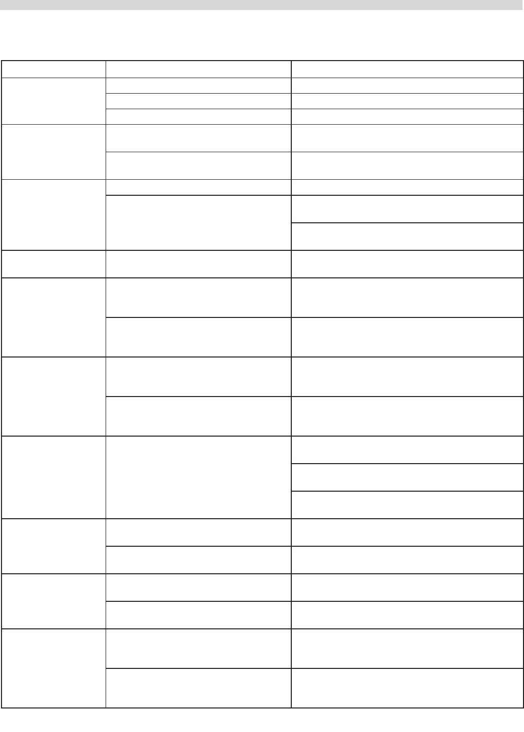
Page 64 Part # MCOSM06 Rev 1 (11/03/08)
GENERAL TROUBLE SHOOTING GUIDE
Problem Possible Cause Corrective Action
Fan will not run A. No Power to Unit A. Turn Power on
B. No power to motor from relay board B. Check for voltage from relay board to motor
C. Micro Switch Not closing C. Check micro switches
Button on key pad not
responding
A. Loose ribbon connection between
key pad and smart board
A. Check that ribbon connection from key pad is
attached to smart board
B. Faulty key pad B. Refer to key pad testing procedure on bulletin
#B-107-2001
'Prob' in display A. Probe disconnected A. Reattach probe
B. Probe has failed B. Conrm ohm resistance of probe. Refer to cavity
probe chart for readings.
C. Check for continuity between probe connection
at relay board, probe harness & probe
Unit will not shut o A. Cavity temperature above 150°F A. Normal operation. Unit will not go to O until
cavity temperature is below 150°F
No HIGH speed but
HIGH speed LED is
illuminated on key pad
A. Bad relay board A. CR3 on relay board should be on, if not check
for 24VDC ±10% at pins 5 & 7 at relay board. If
voltage present replace relay board
B. Bad smart board B. Check for 24VDC ±10% at pins 5 & 7 at relay
board. If voltage is not present replace smart
board
No LOW speed but
LOW speed LED is
illuminated on key pad
A. Bad relay board A. CR4 on relay board should be on, if not check
for 24VDC ±10% at pins 5 & 8 at relay board. If
voltage present replace relay board
B. Bad smart board B. Check for 24VDC ±10% at pins 5 & 8 at relay
board. If voltage is not present replace smart
board
Unit will not heat.
DOOR shown in
display
A. Open circuit on upper door switch A. Unplug unit from supply. With door closed
between NO and COM switch should be open.
B. With door open to 30° angle switch should be
closed
C. With door open all the way switch should be
closed.
Ignition - Lighting
problems
A. Incorrect gas pressure or gas turned
o
A. Check incoming gas pressure
B. Various faults possible B. Refer to trial and ignition ow chart in Section
Two of this manual
Unit will not turn
ON when button is
pushed, display reads
OFF
A. Loose ribbon connection between
key pad and smart board
A. Check connection
B. Faulty key pad B. Refer to key pad testing procedure on bulletin
#B-107-2001
No Display A. No power to smart board A. Check for 24 VAC between pins 1 and 3 on smart
board. If voltage present check for 24 VAC at pins
1 and 3 at relay board.
B. No power to relay board B. Check for 24 VAC into relay board and 24 VAC
out of relay board between pins 1 and 3 on relay
board
Part # MCOSM06 Rev 1 (11/03/08) Page 65
Problem Possible Cause Corrective Action
Burners and fan stay
on when door is open
past 30° opening
A. Loose wire from upper door switch A. Check connections at door switch and relay
board
B. Shorted upper door switch B. Replace upper door switch
Fan runs for a period of
time, shuts down then
comes back on after
several minutes
A. Motor has tripped on internal
overload
A. Check for a minimum 6" clearance at rear of the
unit to a wall or heat source
B. Check air intake vents on back of motor for
obstructions
C. If problem persists and above have been
corrected replace motor assy
Timer slow counting
down
A. Timer is in hours/min A. Refer to operations manual or bulletin
#B-19-2001 on how to change from hour/min to
min/sec
Temperature out of
calibration
A. 400 series controllers A. Conrm oven cavity temp with resistance
change. If out more than 20 OHMs replace probe
B. 200 & 300 series controllers B. Calibration can be performed by repositioning
temperature dial. See Temperature calibration in
manual
C. Potentiometer defective C. Check for proper 'sweep' on potentiometer 0.0 to
10.25 KOHMS

Page 66 Part # MCOSM06 Rev 1 (11/03/08)

Part # MCOSM06 Rev 1 (11/03/08) Page 67
Section Six
Service Bulletins
Page 68 Part # MCOSM06 Rev 1 (11/03/08)
Convection Oven Bulletins
Bulletin # Bulletin Subject Date Issued
B-02-2001 Procedure to Return Parts Jan 11/2001
B-19-2001 410, 450, 455 Controllers Feb 15/2001
B-50-2001 Full Size Convection Oven Door Bushings May 08/2001
B-59-2001 US Range Control Panel Service Kits May 28/2001
B-60-2001 Garland 1/2 Size Control Panel Service Kits May 28/2001
B-61-2001 Garland Control Panel Service Kits May 28/2001
B-107-2001 Convection Oven Keypad Test Points Sep 25/2001
B-110-2001 Full Size Convection Oven Motor Assy Kits Sep 28/2001
B-148-2001 Convection Oven Keypads Nov 22/2001
B-18-2002 Convection Oven Controller Troulbeshooting Feb 14/2002
B-20-2004 Minual Control Panel Conversion Kits Mar 11/2004
B-26-2004 Convection Oven Thermostats Apr 05/2004
B-73-2007-S Rating Plate Motor Return Aug 21/2007
"A" = American
"C" = Canadian
"B" = Both
Part # MCOSM06 Rev 1 (11/03/08) Page 69
Page 70 Part # MCOSM06 Rev 1 (11/03/08)
Part # MCOSM06 Rev 1 (11/03/08) Page 71
Part Number Description Invoice No. Qty Reason for Return Approval Receiver
Customer : _____________________________
Requested By: __________________________
Complete the following details for each item requested to be returned. Fax to 1-800-361-7745
Request For Parts Return Authorization
RGA#
________________________
Request Date:
_______________________
Restocking – Yes
No
Osetting Order – Yes
No
Page 72 Part # MCOSM06 Rev 1 (11/03/08)

Part # MCOSM06 Rev 1 (11/03/08) Page 73
Page 74 Part # MCOSM06 Rev 1 (11/03/08)
Part # MCOSM06 Rev 1 (11/03/08) Page 75
Page 76 Part # MCOSM06 Rev 1 (11/03/08)
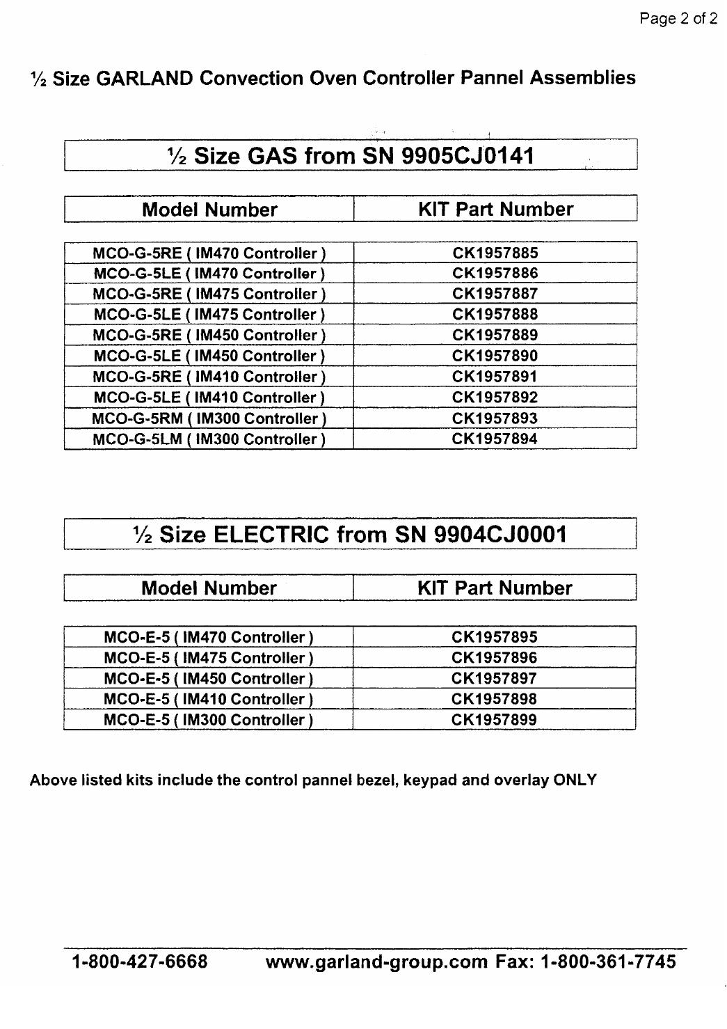
Part # MCOSM06 Rev 1 (11/03/08) Page 77
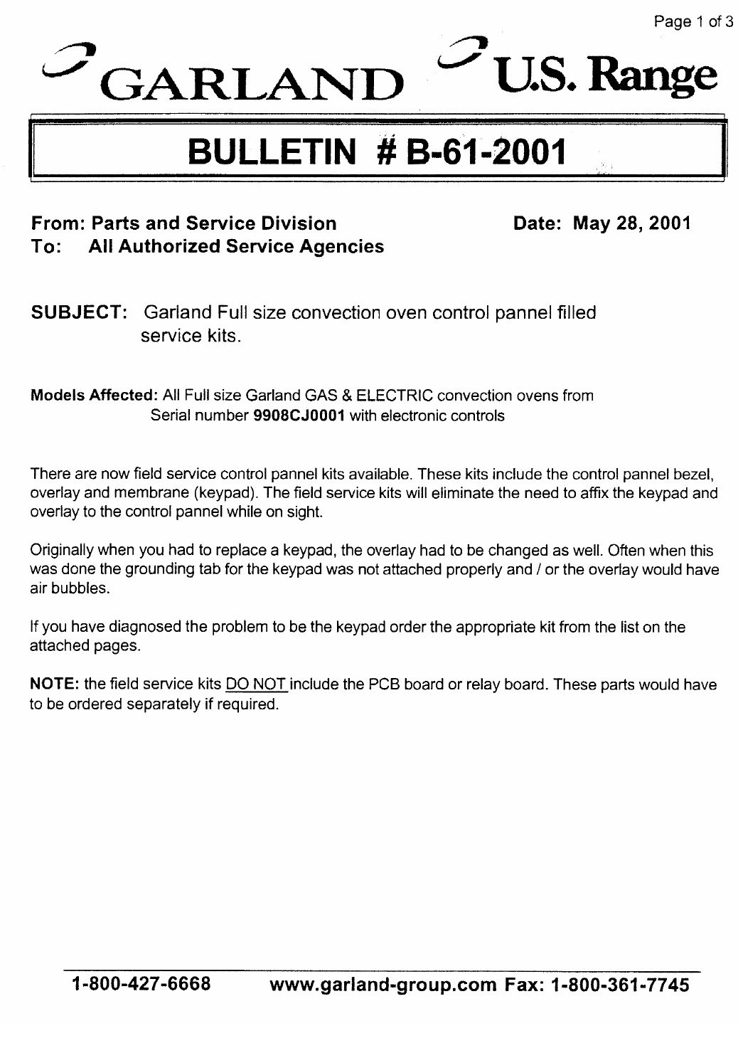
Page 78 Part # MCOSM06 Rev 1 (11/03/08)
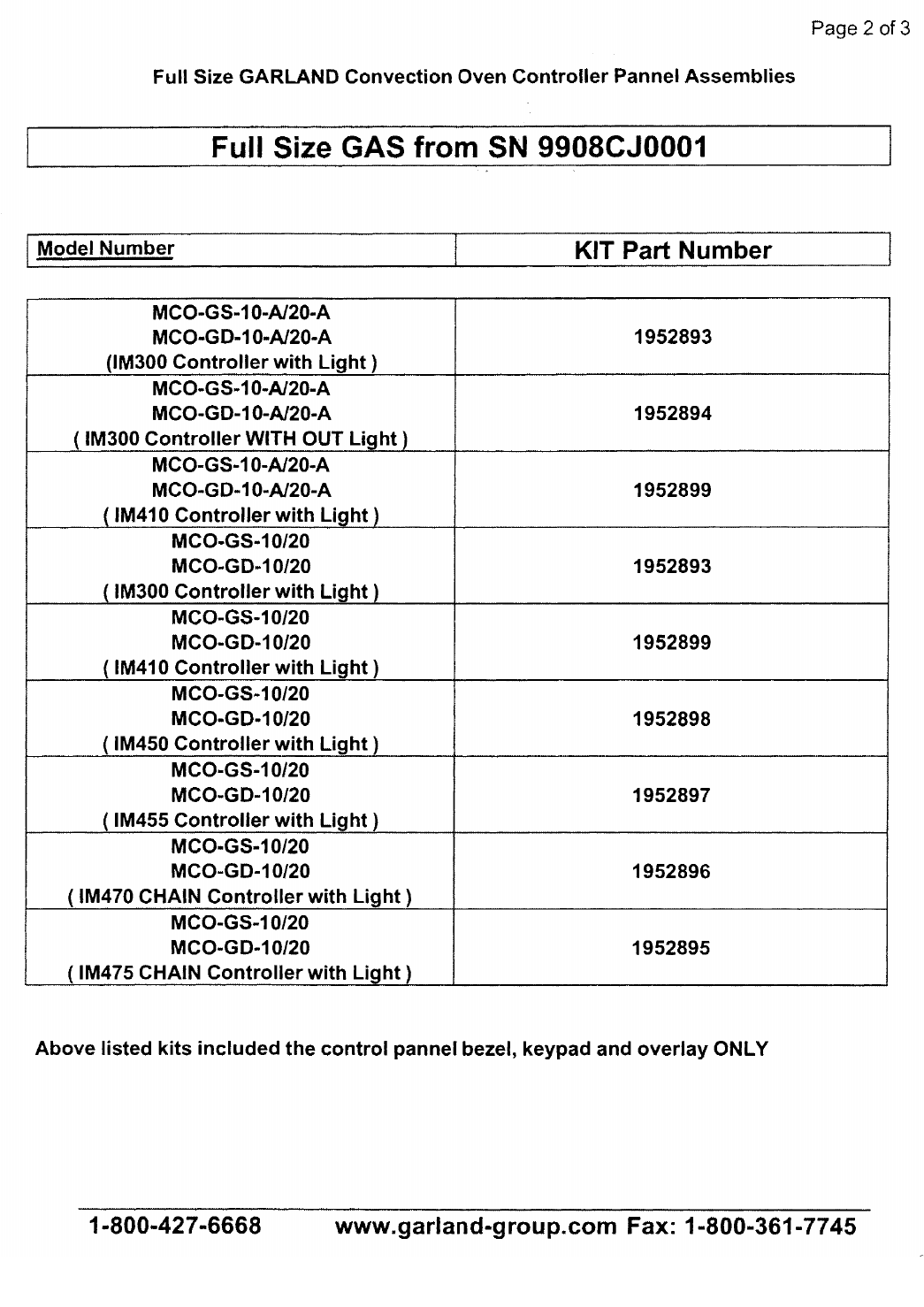
Part # MCOSM06 Rev 1 (11/03/08) Page 79
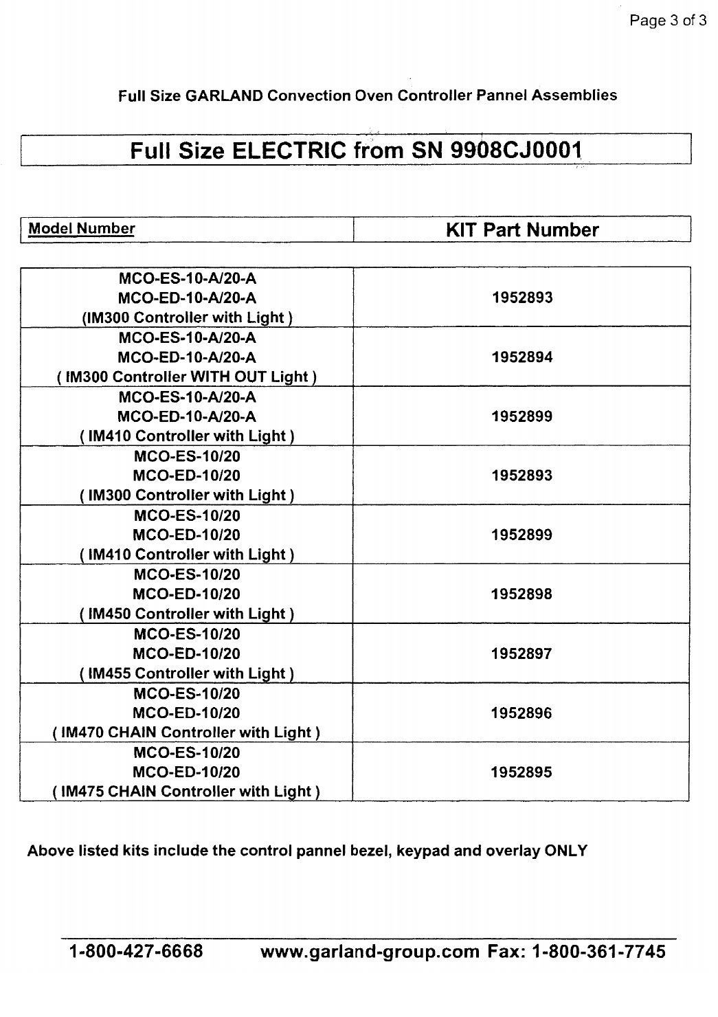
Page 80 Part # MCOSM06 Rev 1 (11/03/08)

Part # MCOSM06 Rev 1 (11/03/08) Page 81
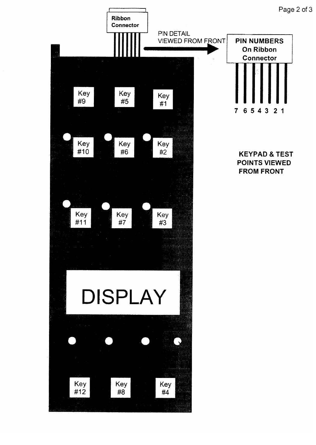
Page 82 Part # MCOSM06 Rev 1 (11/03/08)
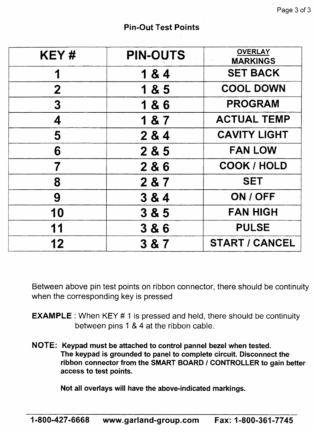
Part # MCOSM06 Rev 1 (11/03/08) Page 83
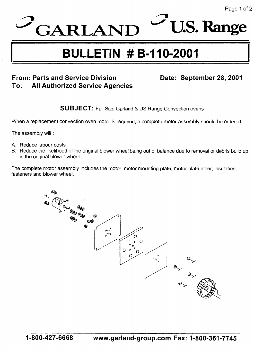
Page 84 Part # MCOSM06 Rev 1 (11/03/08)

Part # MCOSM06 Rev 1 (11/03/08) Page 85
Page 2 of 2
1-800-427-6668 www.garland-group.com Fax 1800-361-7775
Garland
Model #
US Range
Model # Voltage Speed Horsepower Motor Assy.
CK# Motor ONLY
MCOGS
MCOGD
SGE100
SGM100
P1-G-100
115V 2SPD 3/4 hp CK1003090 1686711
MCOGS
MCOGD
SGE100
SGM100 208V/240V 2 SPD 3/4 hp CK1003091 1686712
MCOGS
MCOGD
SGE100
SGM100
P1-G-100
115V/230V 1 SPD 1/2 hp CK1003092 1686703
MCOES
MCOED
SEE100
SEM100 208V/240V 2 SPD 3/4 hp CK1003091 1686712
MCOES
MCOED
SEE100
SEM100 115V/230V 1 SPD 1/2 hp CK1003092 1686703
Garland
Model #
US Range
Model # Voltage Speed Horsepower Motor Assy.
CK# Motor ONLY
ICOG
ECOG
CG100 115V/230V 1 SPD 1/2 hp CK1003099 1686703
ICOG
ECOG
CG100
SDG115V 2 SPD 3/4 hp CK1003095 1686711
ICOG
TIM HORTON’S
‘spritzer’
115V 2 SPD 3/4 hp CK00-011 1686711
ICOE
ECOE
CE100 208V/240V 2 SPD 3/4 hp CK1003094 1686712
Page 86 Part # MCOSM06 Rev 1 (11/03/08)

Part # MCOSM06 Rev 1 (11/03/08) Page 87
Page 1 of 9
1-800-427-6668 www.garland-group.com Fax: 1-800-361-7745
From: Parts and Service Division Date: February 14, 2002
To: All Authorized Service Agencies
SUBJECT: Convection Oven Controller Troubleshooting
MODELS AFFECTED: All Garland & US Range convection ovens
Garland / US Range has been receiving a high level of warranty claims for failed controllers,
Part Numbers 1905701 1905702 1905703 1905704 & 1905705,
that are used on our convection ovens. Analysis of the returned controllers proved that greater
than 70% were without any defects.
In order to reduce the percentage of faulty diagnosis, we have formatted the attached
troubleshooting guide that must be used during future service calls where a controller is suspected
of being faulty.
Be sure to follow the key pad testing procedures as outline in Bulletin # B-107-2001 prior to
performing any testing on the rest of the controller circuit so as to eliminate a potential key pad
problem.
If you do not use this guide and your returned controller is found to be functional, then your claim
will be rejected.
Please contact the Garland / US Range Technical Service Department at (800) 427-6668 with any
questions
BULLETIN # B-18-2002
Page 88 Part # MCOSM06 Rev 1 (11/03/08)
Trouble Shooting Guide
PROBLEM POSSIBLE CAUSE CORRECTIVE ACTION
Fan will not run A. No power to unit
B. No power to motor from
relay board
C. Micro switch no closing
A. Turn power on
B. Check for voltage from relay board
to motor
C. Check micro switches
Button on key pad
not responding A. Loose ribbon
connection between key
pad and smart board
B. Faulty key pad
A. Check that ribbon connection from
key pad is attached to smart board
B. Refer to key pad testing procedure
on bulletin # B-107-2001
‘Prob’ in display A. Probe disconnected
B. Probe has failed A. Re attach probe
B. Confirm ohm resistance of probe.
Refer to cavity probe chart for
readings
C. Check for continuity between probe
connection at relay board, probe
harness & probe
Unit will not shut off A. Cavity temperature
above 150°FA. Normal operation. Unit will not go
to OFF until cavity temperature is
below 150°F
No HIGH speed
BUT HIGH speed
LED is illuminated
on key pad
A. Bad relay board
B. Bad smart board
A. CR3 on relay board should be on, if
not check for 24VDC +/- 10% at
pins 5 & 7 at relay board. If voltage
present replace relay board
B. Check for 24VDC +/- 10%between
pins 5 & 7 at relay board. If voltage
is not present replace smart board
No LOW speed BUT
LOW speed LED is
illuminated on key
pad
A. Bad relay board
B. Bad smart board
A. CR4 on relay board should be on, if
not check for 24VDC +/- 10% at
pins 5 & 8 at relay board. If voltage
is present replace relay board
B. Check for 24VDC +/- 10% at pins 5
& 8 at relay board. If voltage is not
present replace smart board.
Unit will not heat.
DOOR shown in
display
A. Open circuit on upper
door switch A. Unplug unit from supply. With door
closed between NO and COM
switch should be open.
B. With door open to 30° angle switch
should be closed
C. With door open all the way switch
should be closed
Unit will not turn ON
when button pushed,
display reads OFF
A. Loose ribbon
connection between key
pad and smart board
B. Faulty key pad
A. Check connection
B. Refer to key pad testing procedure
on bulletin # B-107-2001
Page 2 of 9
1-800-427-6668 www.garland-group.com Fax: 1-800-361-7745
Part # MCOSM06 Rev 1 (11/03/08) Page 89
Problem Possible Cause Corrective Action
No display A. No power to smart
board
B. No power to relay board
A. Check for 24VAC between pins 1
and 3 on smart board. If voltage
present check for 24VAC at pins 1
and 3 at relay board
B. Check for 24VAC into relay board
and 24VAC out of relay board
between pins 1 and 3 on relay
board
Fan runs for a period
of time, shuts down
then comes back on
after several minutes
A. motor has tripped on
internal thermal
overload
A. check for a minimum 6” clearance
at rear of unit to a wall or heat
source
B. Check air intake vents on back of
motor for obstructions
C. If problem persists and above have
been corrected replace motor assy
Timer slow counting
down A. Timer is in hours / min A. Refer to operations manual or
bulletin # B-19-2001 on how to
change from hour / min to min /
seconds
Temperature out of
calibration A. 400 series controllers
B. 200 & 300 series
controllers
C. Potentiometer defective
A. Confirm oven cavity temp with
resistance chart. If out by more
than 20 Ohms replace probe
B. Calibration can be performed by
repositioning temperature dial.
C. Check for proper ‘sweep’ on
potentiometer. 0 to 10.25KOHMS
RESISTANCE vs. TEMPERATURE CHART FOR INTERNAL OVEN
TEMPERATURE SENSOR
The chart below will provide the Ohms at various temperatures. This will enable
you to determine if the temperature probe is operable.
The chart is degrees Fahrenheit.
TEMP 0° 10° 20° 30° 40° 50° 60° 70° 80° 90°
0° 932 953 974 995 1016 1038 1059 1080 1101 1122
100° 1143 1163 1184 1205 1226 1247 1267 1288 1309 1329
200° 1350 1370 1391 1411 1432 1452 1472 1493 1513 1533
300° 1553 1574 1594 1614 1634 1654 1674 1694 1714 1733
400° 1753 1773 1793 1813 1832 1852 1871 1981 1911 1930
500° 1949 1969 1988 2008 2027 2046 2065 2085 2104 2123
Page 3 of 9
1-800-427-6668 www.garland-group.com Fax: 1-800-361-7745

Page 90 Part # MCOSM06 Rev 1 (11/03/08)
Temperature Calibration
200 & 300 Series Controllers ONLY
Both the 200 & 300 series controllers use a 0 to 10.25K OHM potentiometer.
First check the sweep on the potentiometer between the middle wire and one of
the outside wires for a gradual increase or decrease in the resistance as the
potentiometer stem is turned.
GAS Units – Calibration 300 Series
1. Remove the temperature dial from the potentiometer
2. Turn potentiometer to its lowest setting ( fully counter clock-wise )
3. Place the temperature dial back onto the potentiometer
4. Align the mark on the temperature dial to the top left edge of the ‘F’ on the left
of the temperature dial and snug down one of the set screws. Do NOT fully
tighten yet.
5. Set temperature dial to 150°F and allow oven cavity to reach set temperature
6. Confirm temperature inside the oven cavity with your meter and that shown
on the temperature dial
7. If adjustment is required, loosen set screw and position mark on temperature
dial to temperature shown on your meter.
8. Tighten set screw down
9. Repeat as required (once is usually enough)
10.Fully tighten both set screws
GAS Units – Calibration 200 Series
1. Remove the temperature dial from the potentiometer
2. Turn potentiometer to its highest setting ( fully clock-wise )
3. Place the temperature dial back onto the potentiometer
4. Align the mark on the temperature dial ¼” PAST the 500°F marking on the
overlay and snug down one of the set screws. Do NOT fully tighten yet.
5. Set temperature dial to 150°F and allow oven cavity to reach set temperature
6. Confirm temperature inside the oven cavity with your meter and that shown
on the temperature dial
7. If adjustment is required, loosen set screw and position mark on temperature
dial to temperature shown on your meter
8. Tighten set screw down
9. Repeat as required ( once is usually enough )
10.Fully tighten both set screws
Page 4 of 9
1-800-427-6668 www.garland-group.com Fax: 1-800-361-7745

Part # MCOSM06 Rev 1 (11/03/08) Page 91
ELECTRIC Units – Calibration 300 Series
1. Remove the temperature dial from the potentiometer
2. Turn potentiometer to its lowest setting ( fully counter clock-wise
3. Place the temperature dial back onto the potentiometer
4. Align the mark on the temperature dial to the top left edge of the “F” on the
left of the temperature dial and snug down one of the set screw s. Do NOT
fully tighten yet.
5. Set temperature to 300°F and allow unit to cycle 3-times
6. Confirm temperature inside the oven cavity with your meter and that on the
temperature dial
7. If adjustment is required, loosen the set -screw and position the mark on the
temperature dial to temperature shown on your meter.
8. Tighten set screw down
9. Repeat as required (once is usually enough)
10.Fully tighten both set screws
ELECTRIC Units – 200 Series
1. Remove the temperature dial from the potentiometer
2. Turn potentiometer to its highest setting ( fully clock wise )
3. Place the temperature dial back onto the potentiometer
4. Align the mark on the temperature dial ¼” PAST the 500°F marking on the
overlay and snug down one of the set screws. Do NOT fully tighten yet.
5. Set temperature to 300°F and allow to cycle 3-times
6. Confirm temperature inside the oven cavity with your meter and that on the
temperature dial
7. If adjustment is required, loosen the set-screw and position the mark on the
temperature dial to temperature shown on your meter
8. Tighten set screw down
9. Repeat as required ( once is usually enough )
10.Fully tighten both set screws
Page 5 of 9
1-800-427-6668 www.garland-group.com Fax: 1-800-361-7745

Page 92 Part # MCOSM06 Rev 1 (11/03/08)
Page 6 of 9
1-800-427-6668 www.garland-group.com Fax: 1-800-361-7745
From: Parts and Service Division Date: February 15, 2001
To: All Authorized Service Agencies
SUBJECT: 410, 450, 455 CONTROLLERS
(USED ON GARLAND AND U.S. RANGE CONVECTION OVENS)
CUSTOMER COMPLAINT: Timer will not count down.
We have had a number of calls on this and a lot of controllers have been replaced thinking that there is
a problem with the controller. In most cases, there is nothing wrong with the controller.
They are programmable with a cooking time of up to 99 hours and 59 minutes which means the timer
will count down by minutes when programmed for more than 1 hour.
The timer will count down by seconds if a cooking time of less than 1 hour has been programmed.
A common operator error is to set a time of 5 hours and 30 minutes (for example) when what they
intended to program was a time of 5 minutes and 30 seconds. In this example, the timer will then count
down in minutes instead of seconds and the complaint will be that the timer will not count down or it
counts down too slowly.
If the operator has programmed a time of more than 1 hour, the colon between the numbers will flash
constantly until it drops below 1 hour, after that the colon will remain solid.
COLON FLASHING – Hours/Minutes
COLON SOLID – Minutes/Seconds
To switch from Hours/Minutes to Minutes/Seconds the encoder knob is turned counter-clockwise until
passing the 1 hour mark.
To switch from Minutes/Seconds to Hours/Minutes, the encoder is turned clockwise until passing the 1
hour mark.
Contact a Technical Service Representative for additional information or instructions.
BULLETIN # B-19-2001
Part # MCOSM06 Rev 1 (11/03/08) Page 93
Page 7 of 9
1-800-427-6668 www.garland-group.com Fax: 1-800-361-7745
From: Parts and Service Division Date: September 25, 2001
To: All Authorized Service Agencies
SUBJECT: Convection Oven Keypad Test Points
Models Affected: Garland convection ovens with 300, 410, 450, 455, 470,
475 Controls.
US Range convection ovens with 30, 41, 45, 45+ controls.
There have been a large number of keypads returned as failed to Garland under warranty. A large
number of those returned and tested showed no faults.
The attached test points are a useful service tool to better determine if the problem is with the keypad,
controller, relay board assembly or other.
The attached pages shows the PIN-OUT test points for the keypad used on the above Garland & US
Range convection ovens.
When servicing a unit with reported erratic or non-responsive controls, test the keypad first.
NOTE: Consult operations manual to confirm unit is in normal operations mode.
I.e. “unit will not turn off”. Unit will not go to OFF mode until oven cavity temperature
drops below 150°F. This is a normal operation of the controller in the auto cool down
mode.
BULLETIN B-107-2001
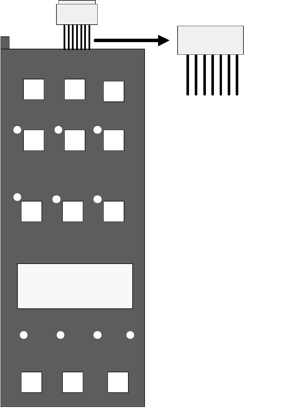
Page 94 Part # MCOSM06 Rev 1 (11/03/08)
Page 8 of 9
PIN DETAIL
VIEWED FROM FRONT
KEYPAD & TEST
POINTS VIEWED
FROM FRONT
Key
#8
Key
#12 Key
#4
Key
#99Key
#5 Key
#1
Key
#10 Key
#6 Key
#2
Key
#11 Key
#7 Key
#3
DISPLAY
X
7 6 5 4 3 2 1
PIN NUMBERS
On Ribbon
Connecto
r
Ribbon
Connector
Part # MCOSM06 Rev 1 (11/03/08) Page 95
Page 9 of 9
1-800-427-6668 www.garland-group.com Fax: 1-800-361-7745
Pin-Out Test Points
KEY # PIN-OUTS OVERLAY
MARKINGS
11 & 4 SET BACK
21 & 5 COOL DOWN
31 & 6 PROGRAM
41 & 7 ACTUAL TEMP
52 & 4 CAVITY LIGHT
62 & 5 FAN LOW
72 & 6 COOK / HOLD
82 & 7 SET
93 & 4 ON / OFF
10 3 & 5 FAN HIGH
11 3 & 6 PULSE
12 3 & 7 START / CANCEL
Between above pin test points on ribbon connector, there should be continuity
when the corresponding key is pressed
EXAMPLE : When KEY # 1 is pressed and held, there should be continuity
between pins 1 & 4 at the ribbon cable.
NOTE: Keypad must be attached to control pannel bezel when tested.
The keypad is grounded to panel to complete circuit. Disconnect the
ribbon connector from the SMART BOARD / CONTROLLER to gain better
access to test points.
Not all overlays will have the above-indicated markings.

Page 96 Part # MCOSM06 Rev 1 (11/03/08)
Page 1 of 1
1-800-427-6668 www.garland-group.com Fax: 1-800-361-7745
From: Parts and Service Division Date: March 11, 2004
To: All Authorized Service Agencies
PRODUCT: Half-Size Garland Gas Convection Ovens
SUBJECT: Manual Control Panel Conversion Kits
Model Affected: Half-Size Garland Gas convection oven models, MCO-G-5LE and MCO-G-
5RE with 300/400 series electronic control panels.
There are now new field service manual control panel kits available for the Garland gas half-size
convection ovens. These two kits include the complete control panel assembly and will convert an
existing 300/400 series electronic control panel to the 200 series manual control panel.
Please make note of the following part numbers for these two kits.
1. Part number 4512251 designed to convert Garland gas models MCO-G-5LE from 300/400
electronic to 200 series manual controls.
2. Part number 4512253 designed to convert Garland gas models MCO-G-5RE from 300/400
electronic to 200 series manual controls.
If you have any questions, please contact the Garland/ US Range Service Department at 1-800-
427-6668.
BULLETIN # B-20-2004

Part # MCOSM06 Rev 1 (11/03/08) Page 97
Page 1 of 1
1-800-427-6668 www.garland-group.com Fax: 1-800-361-7745
From: Parts and Service Division Date: April 5, 2004
To: All Authorized Service Agencies
SUBJECT: Convection Oven Thermostats
Models Affected: Garland ICO & US Range SDG series ovens
We have noticed that the incorrect thermostats are being installed as replacement parts in the
Garland ICO ELECTRIC convection ovens.
Reference Garland bulletin B-66-2002.
The Garland ICO ELECTRIC convection oven requires the use of pn 1032400 thermostat. This
thermostat is rated for 30 AMPS.
The GAS thermostat, pn G02902-01 is rated at 1 AMP. If it is installed in an ELECTRIC
convection oven it will not operate accurately / fail prematurely.
Ensure that the correct thermostat is being installed as a replacement part.
PART NUMBER USED ON MODELS
G02902-01 GAS MCO,ICO, ECO & SDG series convection ovens
with mechanical thermostats
1032400 ELECTRIC MCO, ICO, ECO series convection ovens
with mechanical thermostats
BULLETIN # B-26-2004
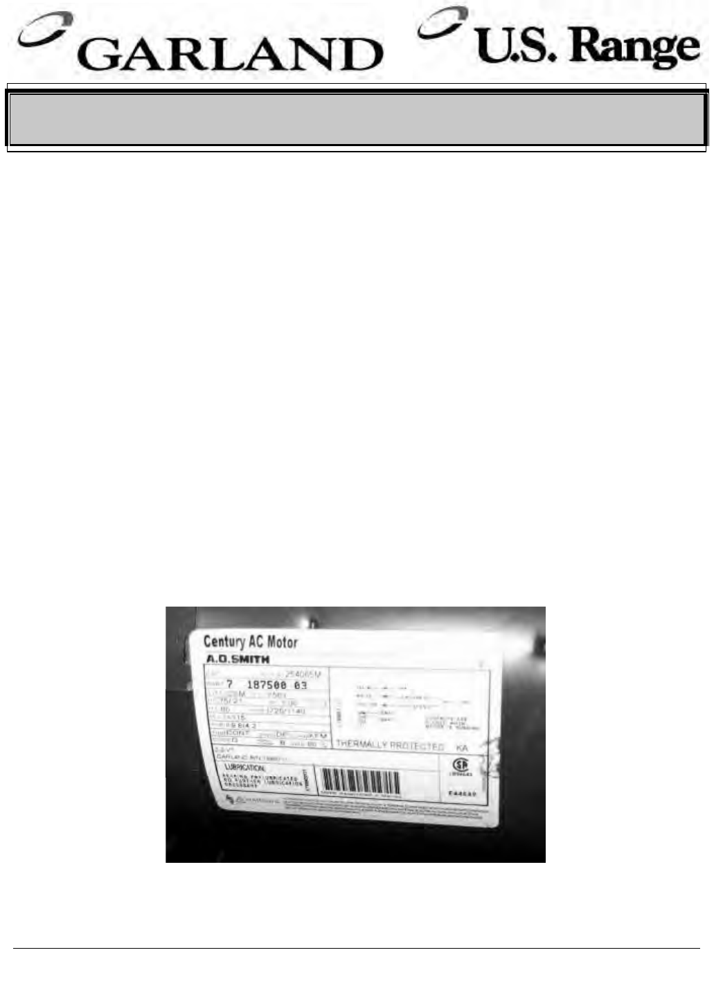
Page 98 Part # MCOSM06 Rev 1 (11/03/08)
Page 1 of 2
A:US C:Canada B:Canada/US I:International S: Service P: Parts W: Warranty G: General
1-800-427-6668 www.garland-group.com Fax: 1-800-361-7745
From: Parts and Service Division Date: August 21, 2007
To: All Authorized Service Agencies
Subject: Rating Plate Motor Return
Model Affected: Garland Convection or Moisture Plus Oven
Effective immediately, when replacing a failed motor for a convection oven or
Moisture Plus oven, it will be necessary for you to return the rating plate label from
the motor along with your warranty claim report and packing slip. If the rating plate
label is not received, credit will not be issued.
Though ServiceBench will treat these parts as mandatory returns, it is no longer
necessary to return the entire motor to the factory; you need only return the rating
plate label from the motor along with the ServiceBench pack list. You can remove
the rating plate label by peeling off the label as shown below. The rating plate label
can be found on the body of the motor. Returns are to be packed and returned
separately from any other component returns.
BULLETIN # B-73-2007-S
Part # MCOSM06 Rev 1 (11/03/08) Page 99
Page 2 of 2
A:US C:Canada B:Canada/US I:International S: Service P: Parts W: Warranty G: General
1-800-427-6668 www.garland-group.com Fax: 1-800-361-7745
The following part numbers are affected by this bulletin on Garland convection and
Moisture Plus ovens:
Part # Description
1686711 Motor 3/4 HP, 115V, 2 Speed
1686712 Motor 3/4 HP, 208/240V, 2 Speed
1686703 Motor 1/2 HP, 115/230V, 1 Speed
1773802 Motor 208/240V 2 Speed
1951501 Motor 110V 1/3HP 2SP 5/8 SHAFT
1951502 Motor 208/240 1/3HP 2SP
CK1003090 Motor Ass'y - 2 Speed - 115V
CK1003091 Motor Ass'y - 2 Speed - 208/240V
Ck1003094 Motor Assembly 2 Speed 208/240
CK1003095 Motor Assembly 2 Speed 115V
CK1003099 Motor Assembly 1 Speed
CK00-011 Motor Kit Tim Hortons
4518320 Kit, Motor Assembly - 240V M+
4518319 Kit, Motor Assembly - 120V
1615001 Motor - 3/4 Hp 115/240V 1725rpm CW/CCW
Please contact The Garland/US Range Technical Service Department with any
question.

Page 100 Part # MCOSM06 Rev 1 (11/03/08)
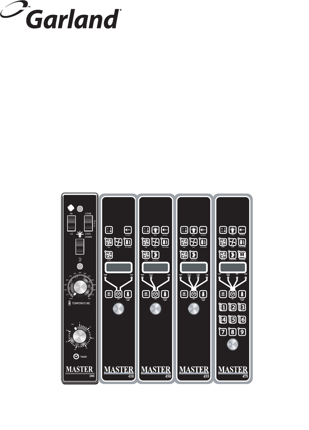
Part # MCOSM06 Rev 1 (11/03/08) Page 101
Section Seven
Wiring Diagrams
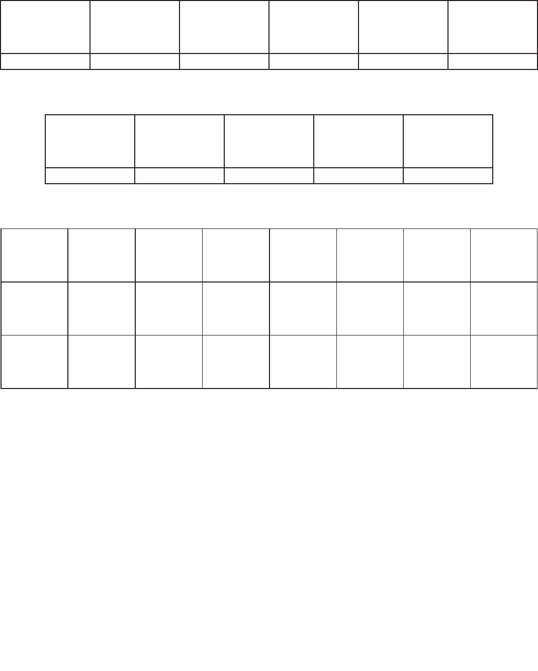
Page 102 Part # MCOSM06 Rev 1 (11/03/08)
Master Convection Ovens Wiring Diagrams
GAS MODELS HoneyWell Ignition Modules
Voltage
200 Controller
(Honeywell
Ignition Module)
300 Controller
(Honeywell
Ignition Module)
400 Controller
(Honeywell
Ignition Module)
200 Controller
(Johnson Ignition
Module)
300 & 400
Controller
(Johnson ignition
Module)
120V 1949511-R02 1807833 1807824 1949511-R03 1949501
GAS MODELS Johnson Ignition Modules
Voltage
200 Controller
(Johnson Ignition
Module)
300 & 400
Controller
(Johnson ignition
Module)
200 Controller
(Johnson Direct
Spark Ignition
Module)
400 Controller
(Johnson Direct
Spark ignition
Module)
120V 1949511-R03 1949501 1949511-R07 1949501-R04
ELECTRIC MODELS
Voltage
Mechanical
Control
1 speed
Mechanical
Control
2 speed
Robershaw
Electronic
Controller
1 Speed
Robershaw
Electronic
Controller
2 speed
200
Controller
300
Controller
400
Controller
208V/240V 1807804 1807803 1807802 1807801 1949514 1807829 1807820
460V 1807812 1807811 1807810 1807809 1949515 1807830 1807830
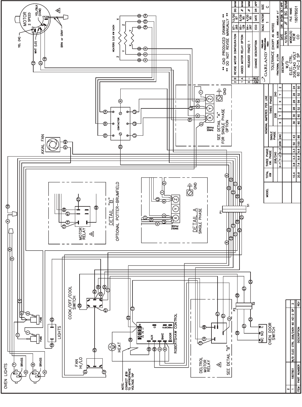
Part # MCOSM06 Rev 1 (11/03/08) Page 103
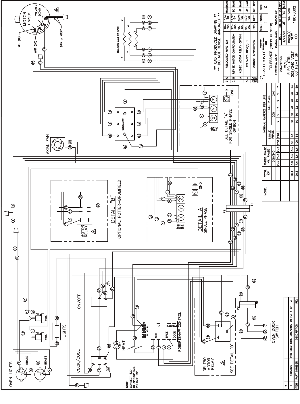
Page 104 Part # MCOSM06 Rev 1 (11/03/08)
Part # MCOSM06 Rev 1 (11/03/08) Page 105
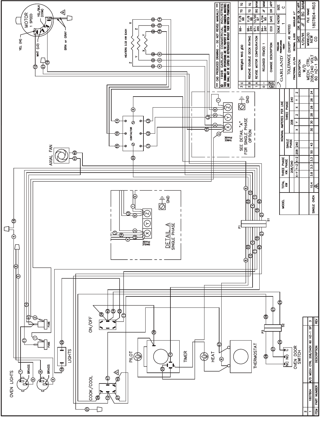
Page 106 Part # MCOSM06 Rev 1 (11/03/08)
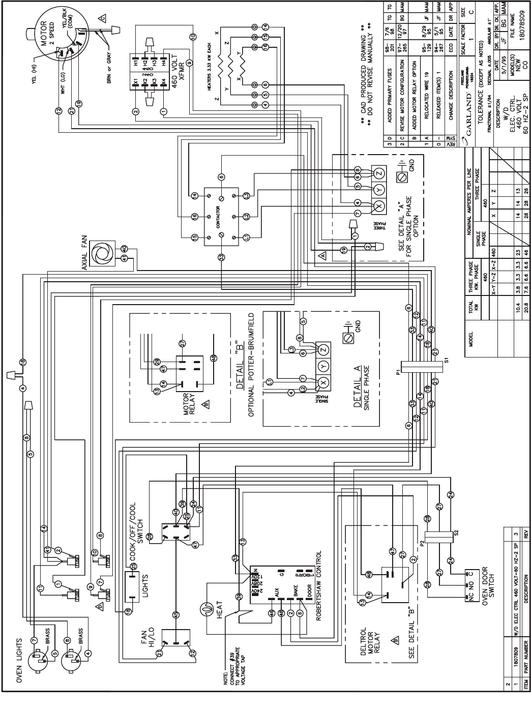
Part # MCOSM06 Rev 1 (11/03/08) Page 107
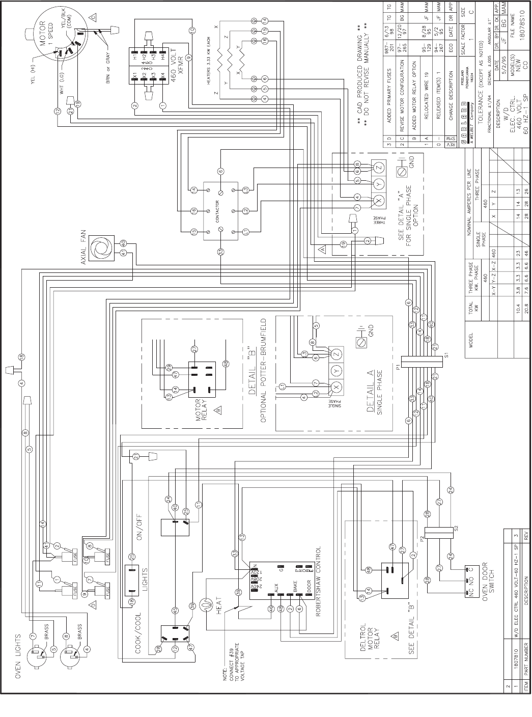
Page 108 Part # MCOSM06 Rev 1 (11/03/08)
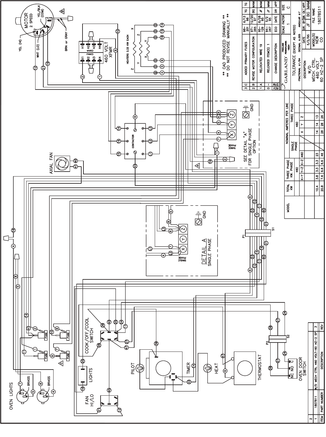
Part # MCOSM06 Rev 1 (11/03/08) Page 109
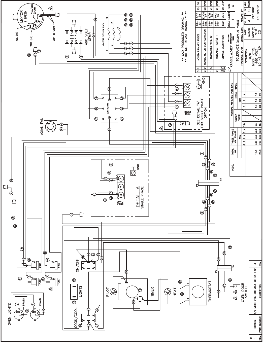
Page 110 Part # MCOSM06 Rev 1 (11/03/08)
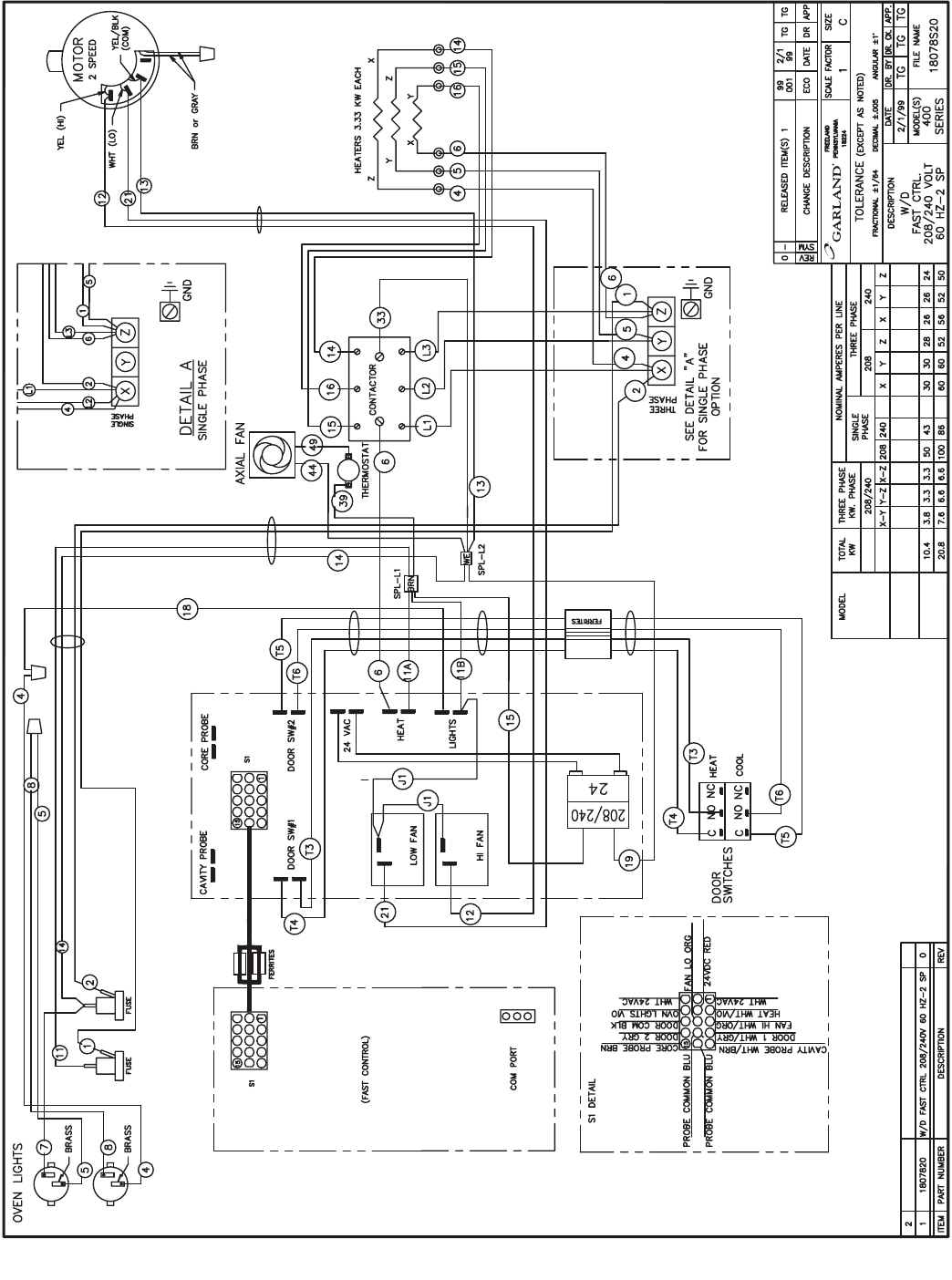
Part # MCOSM06 Rev 1 (11/03/08) Page 111
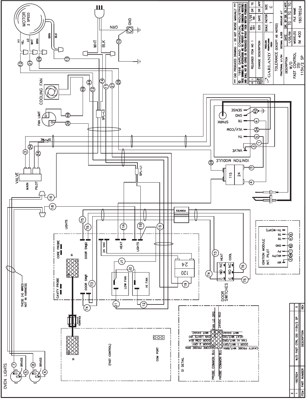
Page 112 Part # MCOSM06 Rev 1 (11/03/08)
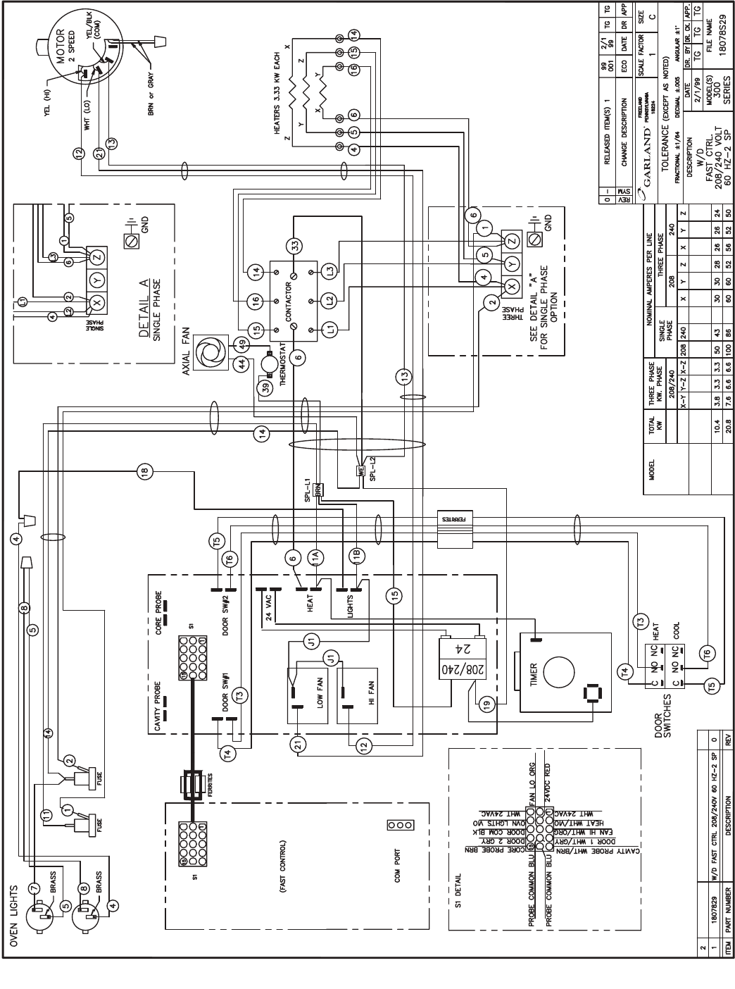
Part # MCOSM06 Rev 1 (11/03/08) Page 113
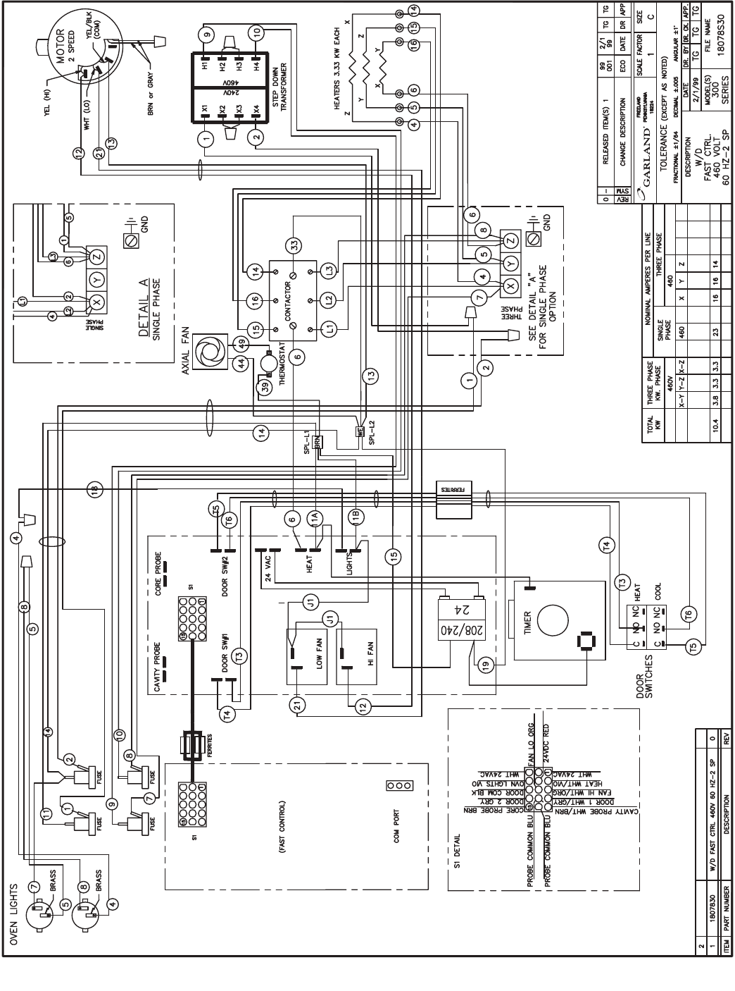
Page 114 Part # MCOSM06 Rev 1 (11/03/08)
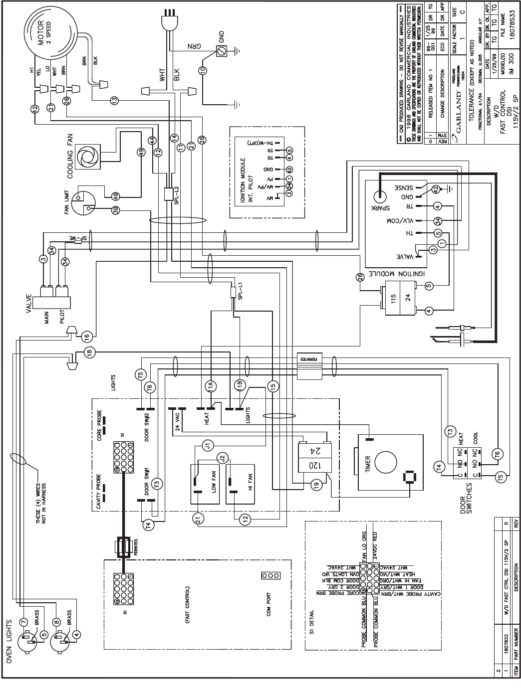
Part # MCOSM06 Rev 1 (11/03/08) Page 115
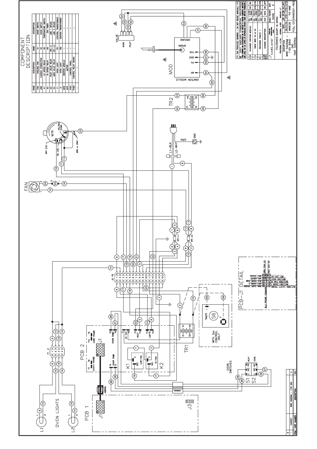
Page 116 Part # MCOSM06 Rev 1 (11/03/08)
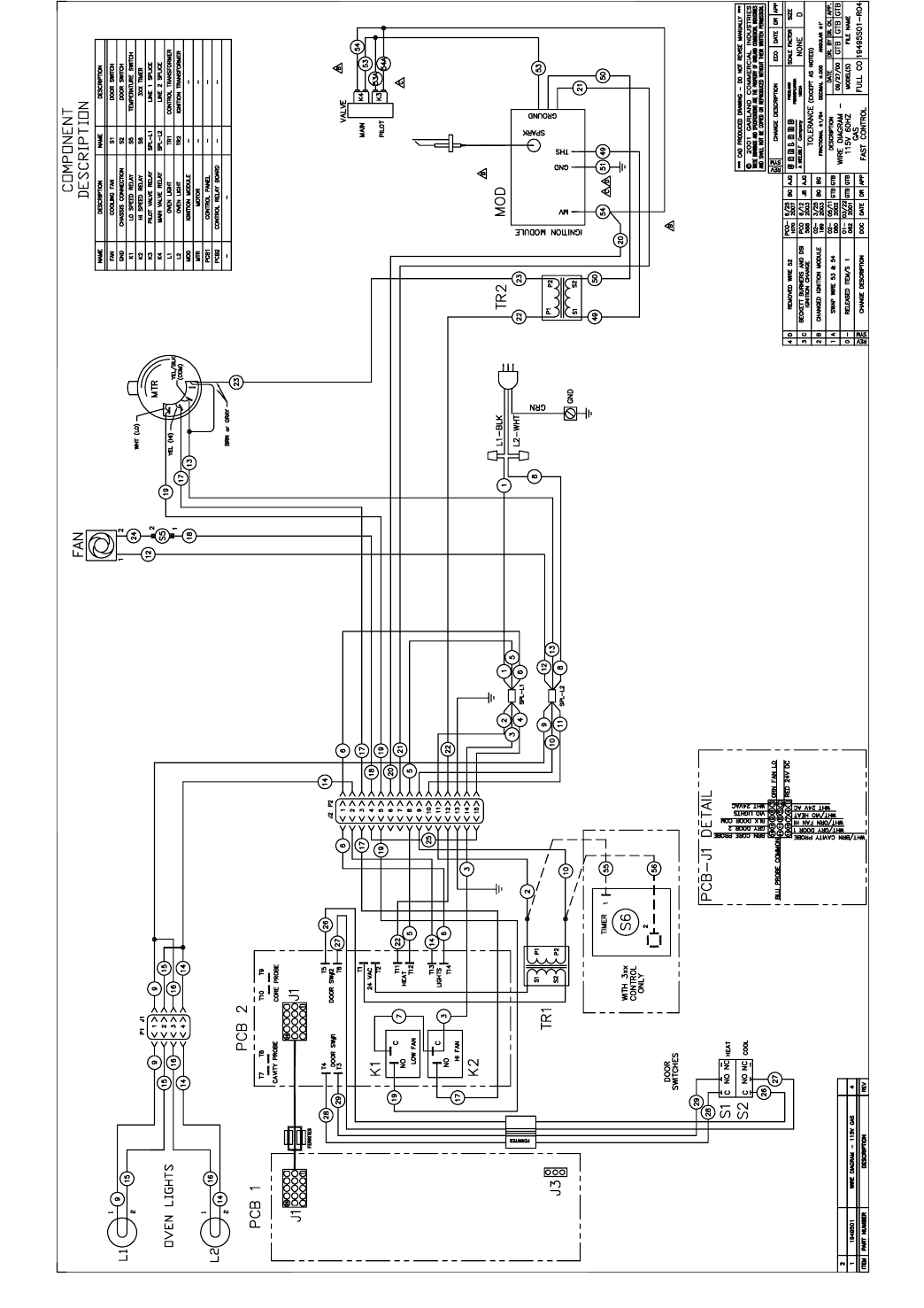
Part # MCOSM06 Rev 1 (11/03/08) Page 117
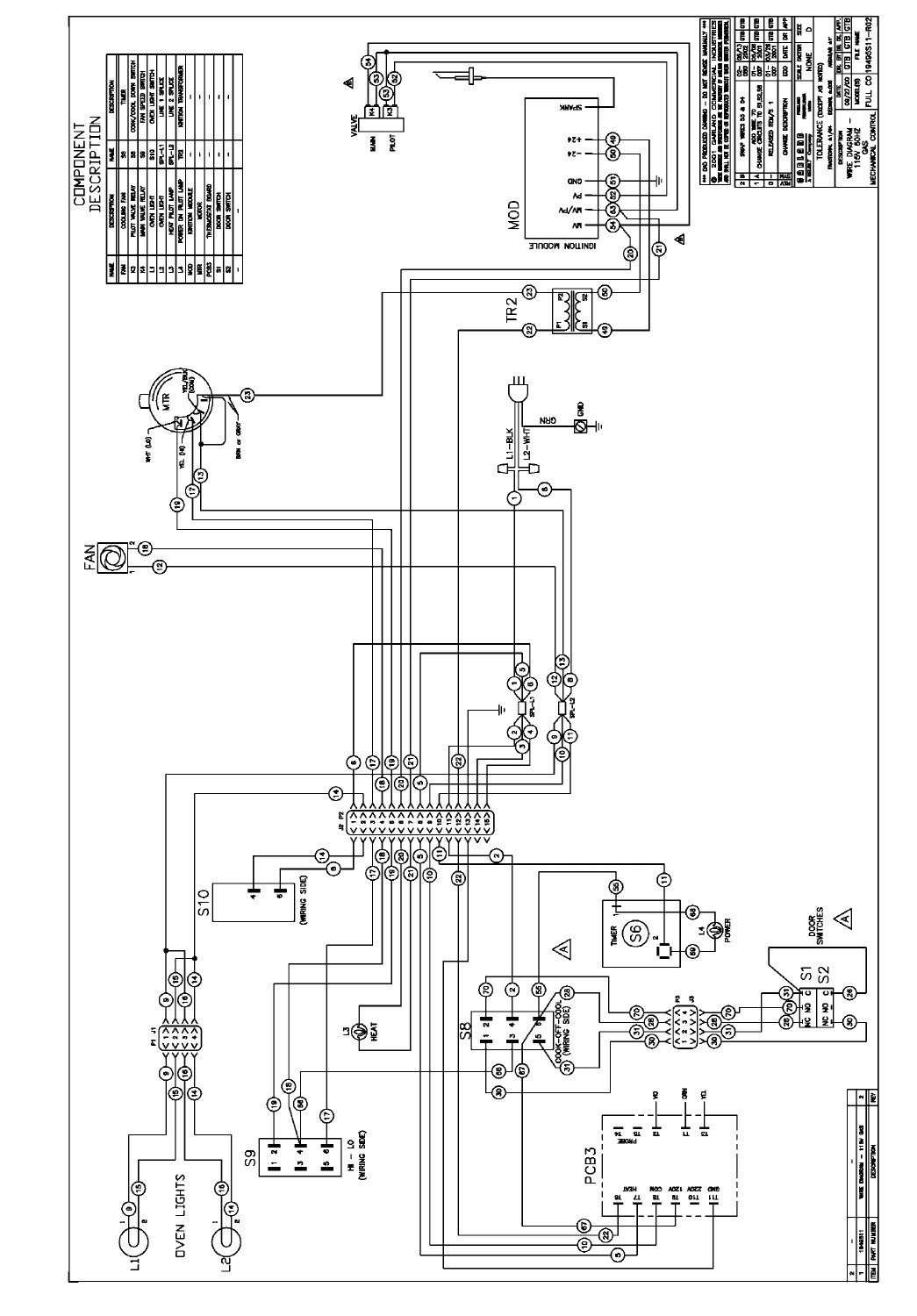
Page 118 Part # MCOSM06 Rev 1 (11/03/08)
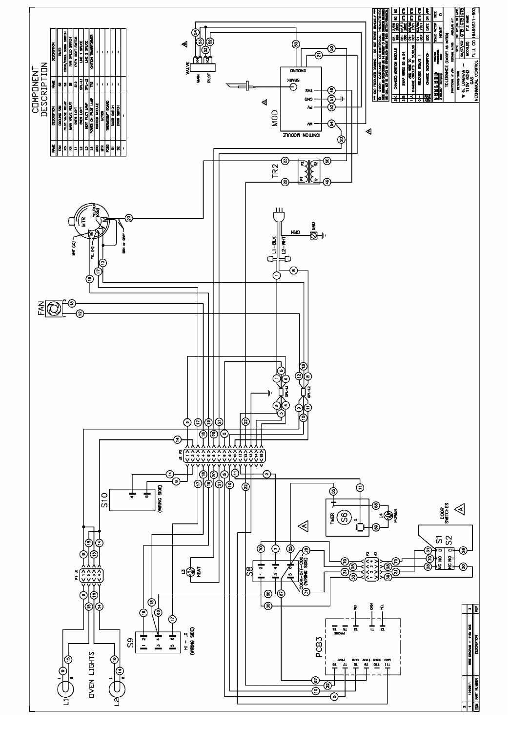
Part # MCOSM06 Rev 1 (11/03/08) Page 119
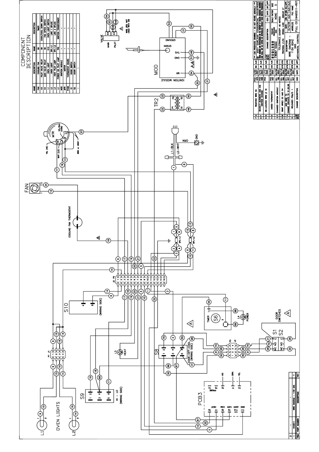
Page 120 Part # MCOSM06 Rev 1 (11/03/08)
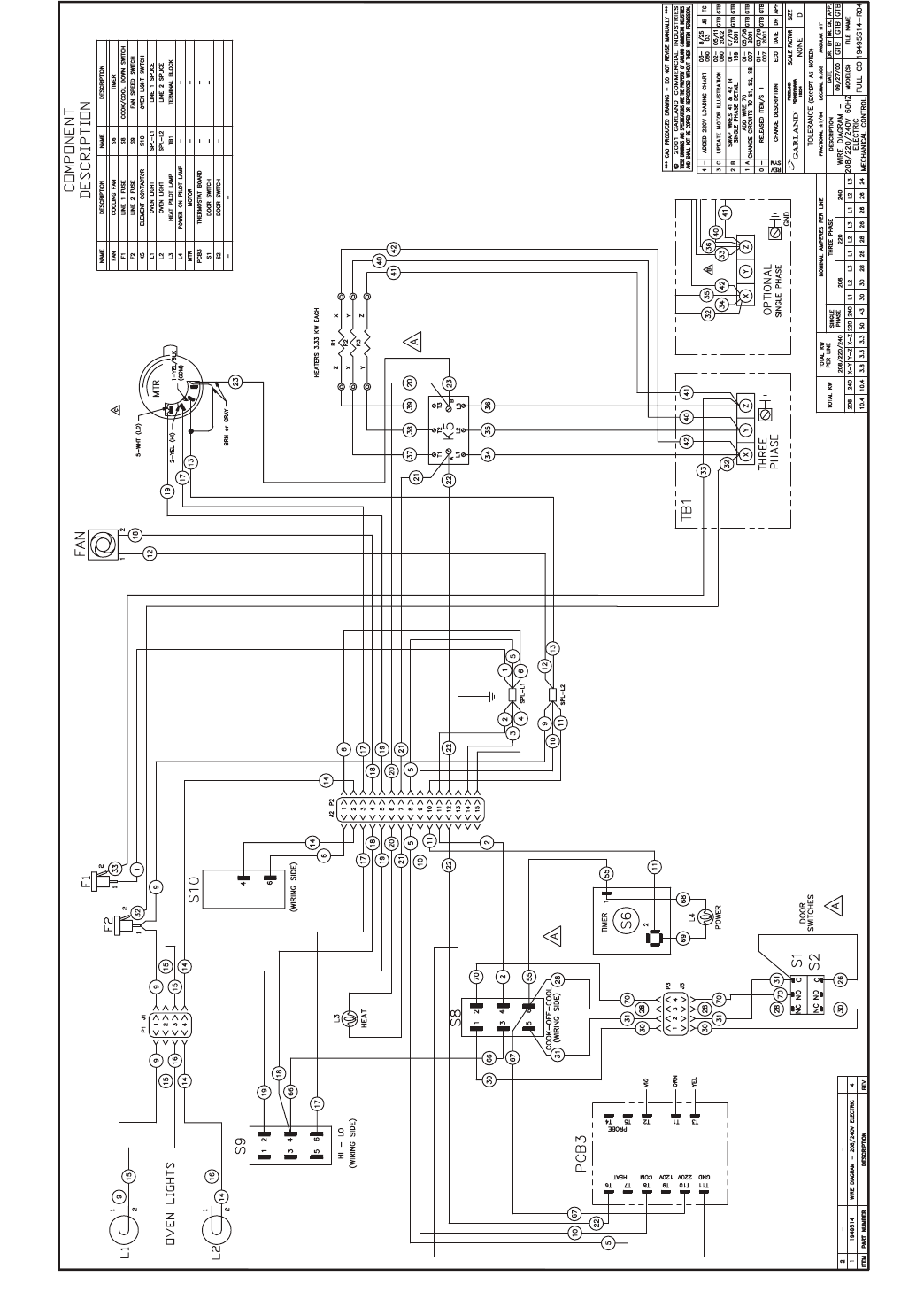
Part # MCOSM06 Rev 1 (11/03/08) Page 121
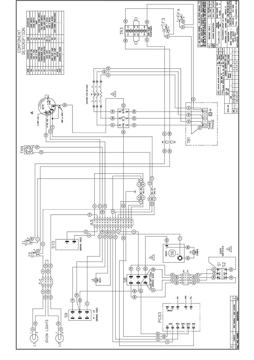
Page 122 Part # MCOSM06 Rev 1 (11/03/08)

Part # MCOSM06 Rev 1 (11/03/08) Page 123

