Garmin AT AT7000 Mode S Datalink Transponder User Manual 560 0405 00 AT7000 Installation Manual Rev
Garmin AT, Inc. Mode S Datalink Transponder 560 0405 00 AT7000 Installation Manual Rev
Manual

AT7000
Mode S Transponder
Installation Manual
December 14, 2001
560-0405-00 Rev. --

Installation Manual AT7000 Mode S Transponder
560-0405-00 Rev –
December 14, 2001
2001 by UPS Aviation Technologies All rights reserved.
Printed in the USA
UPS Aviation Technologies CAGE Number 0XCJ6
No part of this document may be transmitted, reproduced, or copied in any form or by any means
without the prior written consent of UPS Aviation Technologies.
UPS Aviation Technologies and Aviation Technologies are registered trademarks of UPS Avia-
tion Technologies
UPS Aviation Technologies 2345 Turner Rd., SE
PO Box 13549 Salem, OR 97302
Salem, OR 97309 USA
Phone: 503.581.8101
800.525.6726
Fax: 503.364.2138
In Canada: 800.654.3415

Installation Manual AT7000 Mode S Transponder
560-0405-00 Rev –
December 14, 2001
HISTORY OF REVISIONS
Revision EN Date Description
-- EN7149 Dec 14/01 Initial Release
ORDERING INFORMATION
To receive additional copies of this publication, order part # 560-0405-00, AT7000 Mode S
Transponder Installation Manual.
RELATED DOCUMENTS
AT7000 Mode S Transponder Factory Service Manual 560-7016-000

Installation Manual AT7000 Mode S Transponder
560-0405-00 Rev –
December 14, 2001
NOTES

Installation Manual AT7000 Mode S Transponder
560-0405-00 Rev –
December 14, 2001 Page i
© 2001 by UPS Aviation Technologies Inc.
Record of Revisions
For each revision, insert the revised pages into your manual and discard the replaced
pages. On this record page, note the revision number and date, date pages were inserted
into the manual, and the initials of the person inserting the pages.
Revision
Number Revision
Date Date
Inserted By Revision
Number Revision
Date Date In-
serted By

AT7000 Mode S Transponder Installation Manual
Page ii 560-0405-00 Rev –
December 14, 2001
© 2001 by UPS Aviation Technologies Inc.
List of Effective Pages
Section and Page Revision
Title 00
Copyright page 00
History of Revisions 00
List of Effective Pages 00
Table of Contents 00
Sec. 1. Introduction 00
Page 1 00
Page 2 00
Page 3 00
Page 4 00
Sec. 2. System Description 00
Page 5 00
Page 6 00
Page 7 00
Page 8 00
Page 9 00
Page 10 00
Page 11 00
Page 12 00
Sec. 3. Installation
Page 13 00
Page 14 00
Page 15 00
Page 16 00
Page 17 00
Page 18 00
Page 19 00
Page 20 00
Page 22 00
Page 23 00
Page 24 00
Page 25 00
Page 26 00
Page 27 00
Page 28 00
Page 29 00
Page 30 00
Page 31 00
Page 32 00
Page 33 00
Page 34 00
Page 35 00
Page 36 00
Section and Page Revision
Page 37 00
Sec. 4. Post-Install Checkout
Page 38 00
Page 39 00
Sec. 5. Equipment Rem. and Rep.
Page 40 00
Page 41 00
Sec. 6. Operation
Page 42 00
Page 43 00
Sec. 7. Specifications
Page 44 00
Page 45 00
Page 46 00
Page 47 00
Sec. 8. Limitations
Page 48 00
Page 49 00
Sec. 9. Troubleshooting
Page 50 00
Page 51 00
Page 52 00
Page 53 00
Page 54 00
Page 55 00
Page 56 00
Page 57 00
Page 58 00
Page 59 00
Page 60 00
Page 61 00
Page 62 00
Page 63 00
Page 64 00
Page 65 00
Page 66 00
Page 67 00
Sec. 10. Periodic Maintenance
Page 68 00
Page 69 00
Sec. 11. Environmental Qualifications
Page 70 00
Page 71 00

Installation Manual AT7000 Mode S Transponder
560-0405-00 Rev –
December 14, 2001 Page iii
© 2001 by UPS Aviation Technologies Inc.
TABLE OF CONTENTS
SECTION 1 - INTRODUCTION ................................................................................................................ 1
1.1 ABOUT THIS MANUAL .......................................................................................................................1
1.2 SYSTEM DESCRIPTION........................................................................................................................1
1.2.1 System Overview ........................................................................................................................1
1.2.2 AT7000 Mode S Transponder ....................................................................................................2
1.2.3 Control Panel.............................................................................................................................2
1.2.4 Antenna ......................................................................................................................................2
1.2.5 Altitude Source...........................................................................................................................2
1.2.6 Data Link Processor ..................................................................................................................2
1.2.7 TCAS ..........................................................................................................................................2
1.3 FUNCTIONAL OPERATION...................................................................................................................3
1.4 REGULATORY COMPLIANCE...............................................................................................................3
1.4.1 CFR 47, Part 87 (FCC)..............................................................................................................3
1.4.2 TSO C112...................................................................................................................................3
1.4.3 ARINC 718-4 and ARINC 718A.................................................................................................3
SECTION 2 - TRANSPONDER DESCRIPTION ..................................................................................... 5
2.1 GENERAL ...........................................................................................................................................5
2.2 OVERVIEW .........................................................................................................................................5
2.3 AT7000 PRODUCT SUMMARY............................................................................................................6
2.3.1 Gillham to A429 Serial Data Converter.....................................................................................7
2.3.2 Inputs to the AT7000 for Extended Squitter Position Reports....................................................7
2.4 DISPLAY / CONTROL ..........................................................................................................................8
2.5 DATA LOADER INTERFACE.................................................................................................................8
2.6 BUILT-IN TEST EQUIPMENT (BITE) AND DIAGNOSTICS.....................................................................8
2.6.1 Self-Tests ....................................................................................................................................8
2.6.2 Status Indicators.........................................................................................................................9
2.6.3 Maintenance and BITE Data......................................................................................................9
SECTION 3 - INSTALLATION................................................................................................................ 11
3.1 PRE-INSTALLATION INFORMATION ..................................................................................................11
3.2 EQUIPMENT REQUIRED.....................................................................................................................11
3.3 MECHANICAL INSTALLATION...........................................................................................................11
3.3.1 Location of LRUs .....................................................................................................................11
3.3.2 AT7000 Provisions...................................................................................................................11
3.3.3 Antenna Provisions ..................................................................................................................12
3.4 ELECTRICAL INSTALLATION.............................................................................................................13
3.4.1 Middle Plug..............................................................................................................................17
3.4.2 Bottom Plug..............................................................................................................................21
3.4.3 Program Pin Inputs..................................................................................................................23
3.4.4 SDI Program............................................................................................................................23
3.4.5 Max Airspeed Program............................................................................................................23
3.4.6 Antenna Delay Program ..........................................................................................................24
3.4.7 Antenna Program.....................................................................................................................25
3.4.8 Antenna BITE Program............................................................................................................25
3.4.9 Altitude Type Selection.............................................................................................................25
3.5 INTERFACE CONNECTIONS ...............................................................................................................25
3.5.1 Discrete I/O Levels...................................................................................................................25
3.5.2 Gillham Code Altitude Input ....................................................................................................26
3.5.3 Synchro Altitude Input..............................................................................................................26
3.5.4 ARINC 706 Air Data Inputs .....................................................................................................26
3.5.5 Control Panel Input..................................................................................................................26
3.5.6 Standby Input ...........................................................................................................................27
3.5.7 Air/Ground Discrete Inputs......................................................................................................27
3.5.8 Functional Test Discrete Input.................................................................................................27
3.5.9 Altitude Input Selection............................................................................................................28

AT7000 Mode S Transponder Installation Manual
Page iv 560-0405-00 Rev –
December 14, 2001
© 2001 by UPS Aviation Technologies Inc.
3.5.10 Altitude Compare .....................................................................................................................28
3.5.11 Transponder Fail Outputs........................................................................................................28
3.5.12 Flight ID Input .........................................................................................................................29
3.5.13 Data Link Interface ..................................................................................................................29
3.5.14 Downlinked Aircraft Parameters (DAPS)................................................................................29
3.5.15 TX / XT Coord TCAS Interface ................................................................................................29
3.6 DATA LOADER INTERFACE...............................................................................................................30
SECTION 4 - POST-INSTALLATION CHECKOUT............................................................................ 33
4.1 KEY PIN ORIENTATION ....................................................................................................................33
PRE-INSTALLATION CHECKOUT PROCEDURES...........................................................................................33
SECTION 5 - EQUIPMENT REMOVAL AND REPLACEMENT....................................................... 35
5.1 REMOVAL.........................................................................................................................................35
5.1.1 Transponder.............................................................................................................................35
5.2 REPLACEMENT.................................................................................................................................35
5.2.1 Transponder.............................................................................................................................35
SECTION 6 - OPERATION...................................................................................................................... 37
SECTION 7 - SPECIFICATIONS ............................................................................................................ 39
7.1 ELECTRICAL.....................................................................................................................................39
7.2 PHYSICAL.........................................................................................................................................39
7.3 ENVIRONMENTAL.............................................................................................................................40
7.4 TRANSPONDER PERFORMANCE ........................................................................................................40
SECTION 8 - LIMITATIONS................................................................................................................... 43
8.1 INSTALLATION .................................................................................................................................43
SECTION 9 - TROUBLESHOOTING..................................................................................................... 45
9.1 INTRODUCTION AND OVERVIEW.......................................................................................................45
9.1.1 Introduction..............................................................................................................................45
9.1.2 Overview ..................................................................................................................................45
9.2 INTERFACES .....................................................................................................................................46
9.2.1 Buttons .....................................................................................................................................46
9.2.2 Test Status LEDs ......................................................................................................................46
9.2.3 Maintenance Display Pages.....................................................................................................46
9.2.4 Normal Mode ...........................................................................................................................51
9.2.5 Discrete Inputs .........................................................................................................................54
9.2.6 External Interfaces...................................................................................................................55
9.3 TROUBLESHOOTING .........................................................................................................................59
9.3.1 System Test...............................................................................................................................59
SECTION 10 - PERIODIC MAINTENANCE...................................................................................... 61
10.1 MAINTENANCE.................................................................................................................................61
SECTION 11 - ENVIRONMENTAL QUALIFICATIONS ................................................................. 63

Installation Manual AT7000 Mode S Transponder
560-0405-00 Rev –
December 14, 2001 Page v
© 2001 by UPS Aviation Technologies Inc.
LIST OF ILLUSTRATIONS
FIGURE 1 -- AT7000 SYSTEM BLOCK DIAGRAM ............................................................................................. 1
FIGURE 2 – FRONT PANEL OF AT7000............................................................................................................ 6
FIGURE 3 – POTENTIAL EQUIPMENT LOCATIONS........................................................................................... 11
FIGURE 4 - ARINC 600 4 MCU MOUNTING TRAY....................................................................................... 12
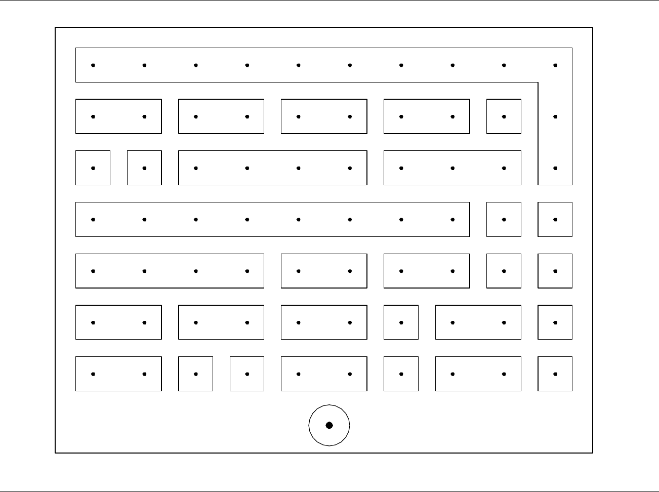
FIGURE 5 – TOP PLUG INTERCONNECT DESCRIPTION (SHEET 1) ................................................................... 13
FIGURE 6 –TOP PLUG CONNECTOR LAYOUT ................................................................................................. 15
FIGURE 7 – MIDDLE PLUG INTERCONNECT DESCRIPTION (SHEET 1)............................................................. 17
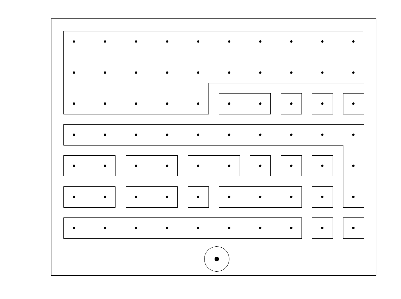
FIGURE 8 – MIDDLE PLUG CONNECTOR LAYOUT ......................................................................................... 19
FIGURE 9 – BOTTOM PLUG INTERCONNECT DESCRIPTION ............................................................................ 21
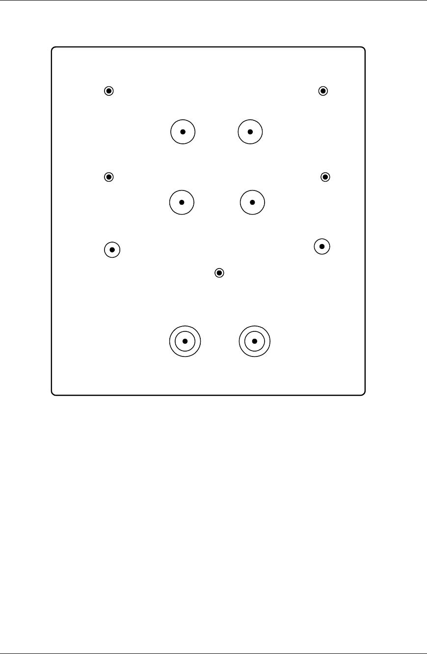
FIGURE 10 – BOTTOM PLUG CONNECTOR LAYOUT....................................................................................... 22
FIGURE 11 – DATA LOADER.......................................................................................................................... 32
FIGURE 12 – REMOVAL OF UNIT FROM TRAY................................................................................................ 35
FIGURE 13 – AT7000 DIMENSIONS............................................................................................................... 40
FIGURE 14. AT7000 MODE S TRANSPONDER .............................................................................................. 45
FIGURE 15. MAINTENANCE DISPLAYS.......................................................................................................... 47
LIST OF TABLES
TABLE 1 - EQUIPMENT FOR INSTALLATION ................................................................................................... 11
TABLE 2 - ANTENNA MINIMUM SPACING...................................................................................................... 12
TABLE 3 - SDI PROGRAM PINS..................................................................................................................... 23
TABLE 4 - MAX AIRSPEED PROGRAM........................................................................................................... 24
TABLE 5 - ANTENNA DELAY PROGRAM ....................................................................................................... 24
TABLE 6 - ALTITUDE TYPE SELECTION ........................................................................................................ 25
TABLE 7 - DATA LOADER PLUG ................................................................................................................... 30
TABLE 8 - STATUS LEDS SUMMARY............................................................................................................ 46
TABLE 9 - TROUBLESHOOTING GUIDE.......................................................................................................... 60
TABLE 10 - ENVIRONMENTAL REQUIREMENTS ............................................................................................. 63

AT7000 Mode S Transponder Installation Manual
Page vi 560-0405-00 Rev –
December 14, 2001
© 2001 by UPS Aviation Technologies Inc.
NOTES
Introduction AT7000 Mode S Transponder
560-0405-00 Rev –
December 14, 2001 Page 1
© 2001 by UPS Aviation Technologies Inc.
Section 1 - Introduction
The AT7000 is a Mode S Data Link Transponder that provides surveillance functions to
ground-based and airborne interrogators. It responds to ATCRBS interrogations as well.
1.1 About This Manual
This manual describes the installation of the UPS Aviation Technologies AT7000 Mode
S Transponder along with a description of the other units that connect to the transponder.
This manual is intended for use by persons certified by the Federal Aviation Administra-
tion (FAA) to install avionics devices. It includes installation and checkout procedures
for the UPS Aviation Technologies AT7000 Mode S Transponder.
1.2 System Description
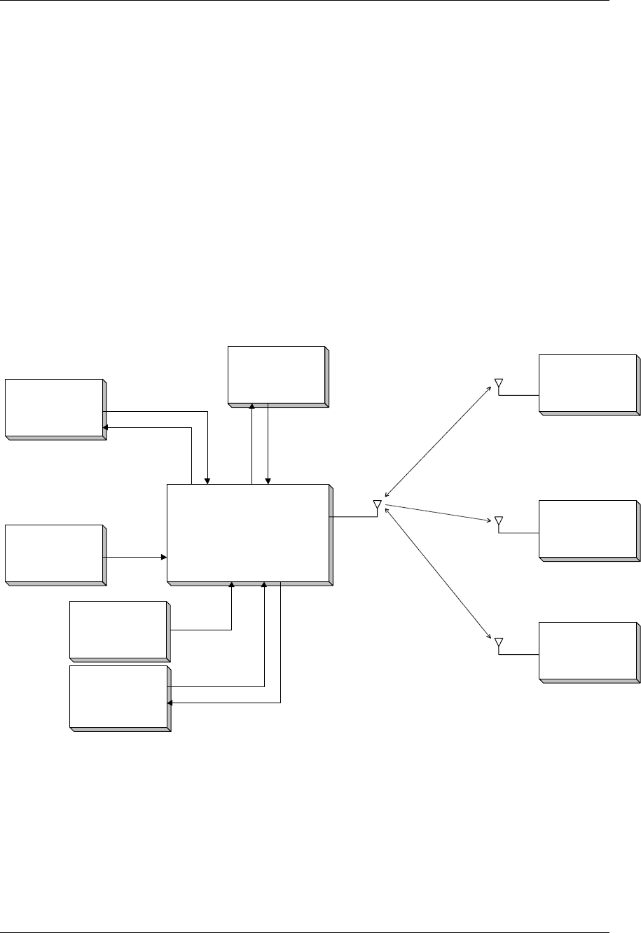
1.2.1 System Overview
Figure 1 -- AT7000 System Block Diagram
AT7000 System Block Diagram
AT7000
Mode S Transponder
TCAS
ATC Radar
Interrogator
Control Panel
TCAS*
Central
Maintenance
Computer
(CMC)*
*Optional (Not
supported in initial
release)
*Optional
Airborne System
1090 Receiver
(ADSB)
ADSB
Airborne Data
Link Processor
(ADLP)*
*Optional
Air Data
Computer
(ADC)

AT7000 Mode S Transponder Introduction
Page 2560-0405-00 Rev –
December 14, 2001
© 2001 by UPS Aviation Technologies Inc.
1.2.2 AT7000 Mode S Transponder
The AT7000 transponder is packaged in a 4-MCU (Modular Concept Unit) outlined as
defined in ARINC Characteristic 600-7. The basic mechanical chassis is constructed of
lightweight aluminum alloy sheet metal. The unit uses forced air cooling per ARINC 404
or 600. ARINC standard LRU restraints are used as means of holding the transponder in
the mounting rack or tray. The maximum weight of the transponder is 11.5 pounds (5.2
kilograms). The rear connector receptacle is a size 2-shell assembly with inserts and
contacts as defined in ARINC Characteristic 718-4/718A. The unit features a fixed car-
rying handle, self-test switch with discrete LED STATUS annunciators, and a LCD dis-
play for system setup and verification.
1.2.3 Control Panel
The control panel for the Mode S System provides for mode control of the ATC Trans-
ponders. Communication with the Mode S Transponders is accomplished via an ARINC
429 bus as defined in ARINC Characteristic 718. Control panel functions includes a
4096-ident code selection and display, altitude source and mode control switch, and se-
lection between two onboard transponders. The control panel also input FID into the
transponder.
1.2.4 Antenna
When installing the transponder antennas, a TSO’d antenna should be selected. Two an-
tennas are required. Having two antennas (one on top of the aircraft and one on the bot-
tom) provides the best coverage for receiving interrogations from ground radar, planes
above, and below. L-Band type recommended antennas are P/N S65-5366-7L, manu-
factured by Sensor Systems and P/N DM N150-2, manufactured by DM Antenna Tech-
nologies.
1.2.5 Altitude Source
The transponder contains dual inputs for acceptable types of altitude sources. The pin
configuration selection specifies which of the two inputs are used for obtaining altitude
information. Altitude sources are ADC (429), Synchro, or Gillham. The input uses a
ground/open logic level, where a ‘ground’ logic level specifies altitude source #2, and an
‘open’ logic level specifies altitude source #1.
1.2.6 Data Link Processor
Four high speed ARINC 429 busses are provided for interfacing to a Mode S Airborne
Data Link Processor (ADLP). The Comm A/B input and Comm A/B output busses are
used for transferring messages to and from the ADLP.
1.2.7 TCAS
The AT7000 contains an interface that allows it to work with an onboard TCAS II sys-
tem. The interface consists of two ARINC 429 high speed data busses, an XT Coordina-
tion bus that is an output from the transponder to TCAS, and a TX Coordination bus that
is an output from TCAS to the transponder.

Introduction AT7000 Mode S Transponder
560-0405-00 Rev –
December 14, 2001 Page 3
© 2001 by UPS Aviation Technologies Inc.
1.3 Functional Operation
Mode S System operation begins when aircraft power is applied. An initial self-test is
performed automatically upon power-up and is completed in approximately one second.
Self-testing of the transponder occurs continuously while powered on. If a transponder
failure occurs, it is indicated on the control panel. Other failures are indicated via front
panel mounted LEDs on the transponder, however, these failure indications are not avail-
able to the pilot. All failures, whether hard or intermittent, are recorded in the trans-
ponder maintenance memory for analysis by maintenance personnel.
1.4 Regulatory Compliance
The following standards are described in relationship to the functioning and certification
of the AT7000.
1.4.1 CFR 47, Part 87 (FCC)
Aviation Services, Subpart D, Technical Requirements
1.4.2 TSO C112
The AT7000 complies with TSO C112, Air Traffic Control Radar Beacon System/Mode
Select (ATCRBS/Mode S) Airborne Equipment.
1.4.3 ARINC 718-4 and ARINC 718A
The AT7000 complies with ARINC Characteristic 718-4 and 718A, Mark 3 Air Traffic
Control Transponder. The AT7000 meets the minimum subset of ARINC 718A and is
software upgradeable for most DAPS parameters. See Transponder Description, Section
2.

AT7000 Mode S Transponder Introduction
Page 4560-0405-00 Rev –
December 14, 2001
© 2001 by UPS Aviation Technologies Inc.
NOTES

Installation Manual System Description
560-0405-00 Rev –
December 14, 2001 Page 5
© 2001 by UPS Aviation Technologies Inc.
Section 2 - Transponder Description
2.1 General
This section defines the system functionality for the AT7000 Mode S transponder. It is a
Level 2es transponder indicating that it performs basic Mode S functions, and is also ca-
pable of transmitting extended squitters with encoded aircraft information to support
ADS-B functions. The unit is also upgradeable to ICAO Level 5 (Downlinked Aircraft
Parameters, (DAPS)) capability through software upgrades.
2.2 Overview
The AT7000 transponder is a full-featured Mode S transponder in an ARINC 600 form
factor that has been designed with a built-in capability for future growth. This trans-
ponder is compatible with Change 7 TCAS systems, as well as UPS AT ADS-B systems.
When utilized with a UPS AT Link and Display Processing Unit (LDPU), the unit serves
as an integral part of a complete ADS-B system. ADS-B is currently certified for use as a
traffic surveillance system.
The AT7000 responds to both the Air Traffic Control Radar Beacon System (ATCRBS),
and Mode S (Mode Select) interrogations. The AT7000 meets all requirements described
in DO-181B and EUROCAE ED-73A. This also meets Eurocae elementary surveillance
requirements including SI capability (six bit Mode S sensor interrogator codes) and flight
ID transmission. Flight ID (FID) may be input to the AT7000 for extended squitter
transmission by either external serial data interface or by using a Gables transponder
control panel capable of accepting and transmitting FID information.
TCAS is fully supported with antenna diversity (top and bottom) antenna ports. The
AT7000 is designed to operate with all ARINC 718/735 and conforming TCAS II com-
puters.
To provide maximum reliability, the unit has extensive built in test and evaluation (BITE)
capabilities. This is further augmented by a LCD display on the front panel allowing for
display of descriptive messages allowing for far greater comprehensive testing and trou-
bleshooting capabilities on aircraft.
Software on board the AT7000 is certified to DO-178B Level B. Software updates can
be completed via an RS232 serial data and will be upgraded to interface with an ARINC
615 data loader. The data loader port is located on the front panel of the unit.
System Description Installation Manual
Page 6560-0405-00 Rev –
December 14, 2001
© 2001 by UPS Aviation Technologies Inc.
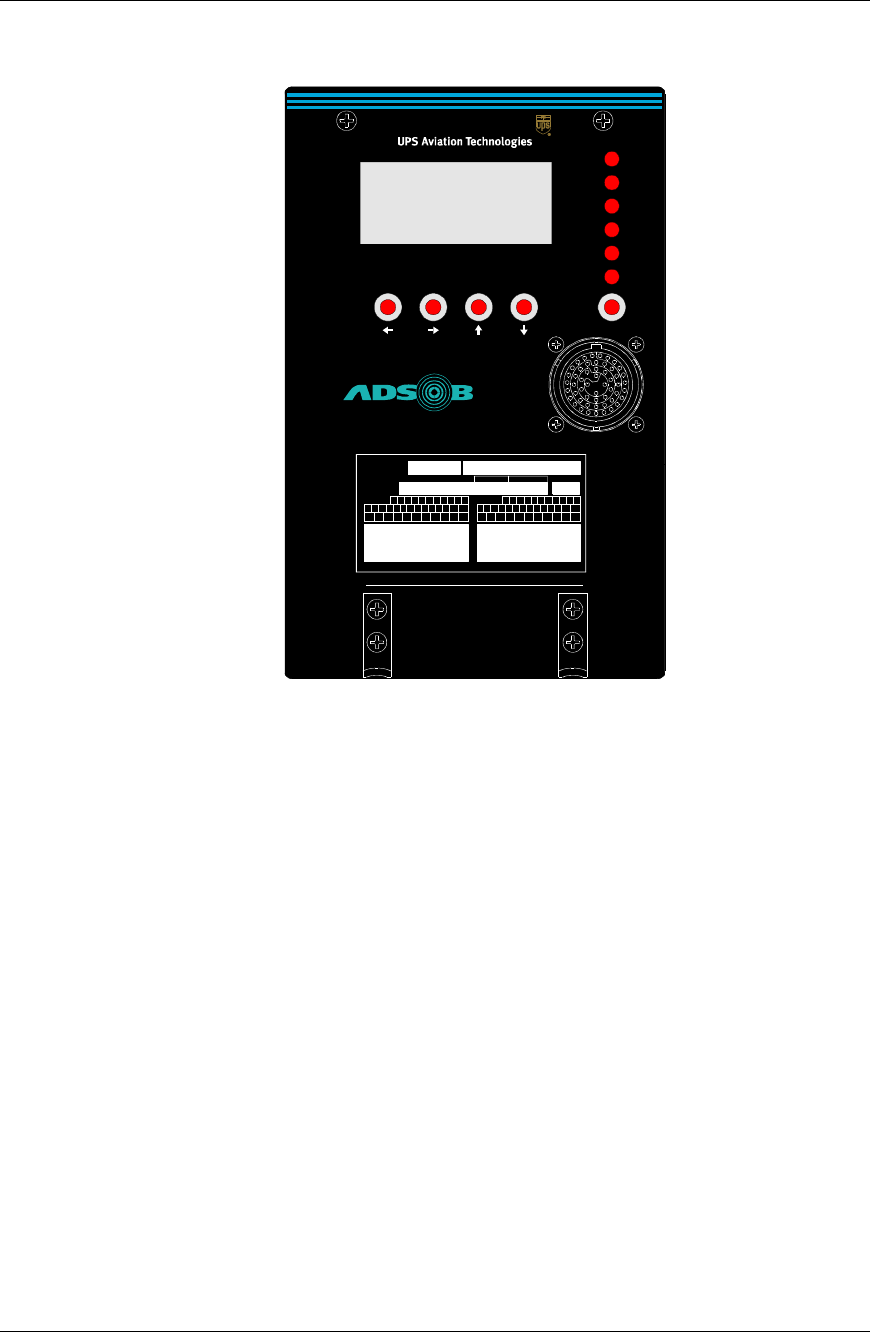
Figure 2 – Front Panel of AT7000
2.3 AT7000 Product Summary
The transponder is an ARINC 718-4/718A mode S transponder.
General features of the transponder includes:
• ARINC 718-4/718A compliant, ARINC 600 format and interconnect, with 4
MCU size form factor
• ATCRBS and Mode S operation
• TSO-C112 certification
• Includes Comm A and Comm B operation, (Comm C, Comm D, and DAPS
capable.)
• Includes extended squitter capability
• Supports Mode S services
• Operates from 115 volts AC, 400Hz, or 28 volts DC
• Transmit power of 400 watts typical
• Includes built-in self-test and diagnostics
MAINTENANCE DISPLAY
XPDR PASS
XPDR FAIL
CTRL PNL
ALT
TOP ANT
BOT ANT
TEST
DATA LOADER
AT7000
Mode S Data Link Transponder
barcode of serial number
SN '1234567'
UPS Aviation Technologies, Salem OR USA
Model:
AT7000
PN:
430-6091 - 00 - 00
SW Mod
TSO-C112 Class 2A7, 121, 011
RTCA/DO-178B Software Level B
RTCA/DO-160D Env. Cat.
FCC ID xxxxxxx
Mode S Transponder
C
AA
D
E
AB
AC
B
A
F
G
H
J
K
L
Z
Y
X
W
V
U
T
S
R
P
N
M
AD
AE
AF
AG
AH
AJ
AK
AL
AM
AN
HW Mod
C
AA
DE
AB
AC
BA FGHJKL
ZYXWVUTSRPNM
AD
AE
AF
AG
AH
AJ
AK
AL
AM
AN
Software
Map/Database
Weight
10.0 lbs.

Installation Manual System Description
560-0405-00 Rev –
December 14, 2001 Page 7
© 2001 by UPS Aviation Technologies Inc.
2.3.1 Gillham to A429 Serial Data Converter
The AT7000 includes a Gillham code to ARINC 429 serial data converter integral to the
unit to support installation in non-ADC equipped aircraft needing serial altitude data.
This is compliant to ARINC 706-4 output.
2.3.2 Inputs to the AT7000 for Extended Squitter Position Reports
Some users of the AT7000 may not wish to install an ADLP concurrently with the trans-
ponder, but wish to output basic position reports to comply with future European re-
quirements. This may be accomplished by inputting the required ARINC labels to the
transponder. The minimum label set is as follows for airborne position squittering:
Minimal Necessary Labels
Label # Description Minimum Rate Alternate Labels
110 (120) Latitude (Fine) 5 Hz 310
111 (121) Longitude (Fine) 5 Hz 311
150 Time Word 5 Hz
140 Fractional Seconds
(should be last word of
data block)
5 Hz
130 HPL 5 Hz 247
377 Equipment ID – must be
142 0.5 Hz

System Description Installation Manual
Page 8560-0405-00 Rev –
December 14, 2001
© 2001 by UPS Aviation Technologies Inc.
Minimal Necessary Labels (Only Type 1&2 or Type 3&4 Required)
Label # Description Minimum Rate Alternate Labels
174 NS Velocity – Type Code
1&2 5 Hz 103 and 112
(or 311 and 312)
166 EW Velocity – Type
Code 1&2 5 Hz 103 and 112
(or 311 and 312)
OR
320 Magnetic Heading – Type
Code 3&4 5 Hz
210 True Airspeed – Type
Code 3&4 (from ADC) 5 Hz 206
2.4 Display / Control
The transponder is designed to work with a standard transponder control panel. The
control panel may output FID for transmissions.
2.5 Data Loader Interface
The transponder includes a front panel mounted data loader interface connector. The in-
terface connector will include an RS-232 serial interface for use with a PC. An ARINC
615 input is provisioned, but not implemented in the software for the initial product re-
lease.
2.6 Built-In Test Equipment (BITE) and Diagnostics
The transponder includes a built-in test and diagnostics to automatically test the trans-
ponder functions at system power up and monitor the operation performance during nor-
mal operation.
2.6.1 Self-Tests
The built-in tests include the following and are completed at power up of the transponder.
a) power supply voltages
b) memory checks
c) transmitter (monitor replies)
d) synthesizers
e) transponder interfaces
f) top and bottom antenna test

Installation Manual System Description
560-0405-00 Rev –
December 14, 2001 Page 9
© 2001 by UPS Aviation Technologies Inc.
2.6.2 Status Indicators
The transponder includes status indicators on the front panel of the unit that can be easily
viewed with the unit installed in its standard mounting. The purpose of the status indica-
tors is to help determine the source of a potential failure to determine the fault condition.
The status indicators includes status for the following conditions:
a) transponder pass/fail
b) control panel failure
c) top antenna failure
d) bottom antenna failure
e) altitude compare failure
The unit also has a LCD front panel display that allows for descriptive text messages to
be displayed for the purpose of determining aircraft system faults, as well as transponder
faults.
2.6.3 Maintenance and BITE Data
The transponder is capable of outputting maintenance data using the data loader interface.
An RS-232 interface is supported.
The transponder includes maintenance data that can be output on the test data interfaces.
The data includes the following:
a. aircraft system power On/Off times, aircraft Airborne/Ground times.
b. power on cycle count
c. airframe cycle count (air/ground cycle count)
d. fault identification (if applicable)

System Description Installation Manual
Page 10 560-0405-00 Rev –
December 14, 2001
© 2001 by UPS Aviation Technologies Inc.
NOTES
Installation Manual Installation
560-0405-00 Rev –
December 14, 2001 Page 11
© 2001 by UPS Aviation Technologies Inc.
Section 3 - Installation
This section describes the installation of the AT7000 Mode S Transponder.
3.1 Pre-Installation Information
The transponder can be mounted in any convenient location in the E/E bay; however, it
should be mounted within 50 feet of the antenna unless a low-loss coaxial cable is used to
maintain a worst case loss of 3 dB per ARINC 718-4/718A. Top and bottom coaxial run
length differences can be compensated for by use of the antenna delay program pins. See
Figure 4, TP3C through TP3F The unit can utilize external cooling air in accordance
with ARINC 600, ARINC 404, or operate in convection cooled environments. However
cooled, the airflow rate provided to the transponder should be 13 kg/hr and the pressure
drop of the coolant air flow through the equipment should be 5 + 3mm of water.
3.2 Equipment Required
Table 1 - Equipment for Installation
LRU Mating Connector Qty/System
AT7000 NSXN2P203X0105 1
3.3 Mechanical Installation
3.3.1 Location of LRUs
The AT7000 is located in the E/E bay. The Control Panel is located in the cockpit.
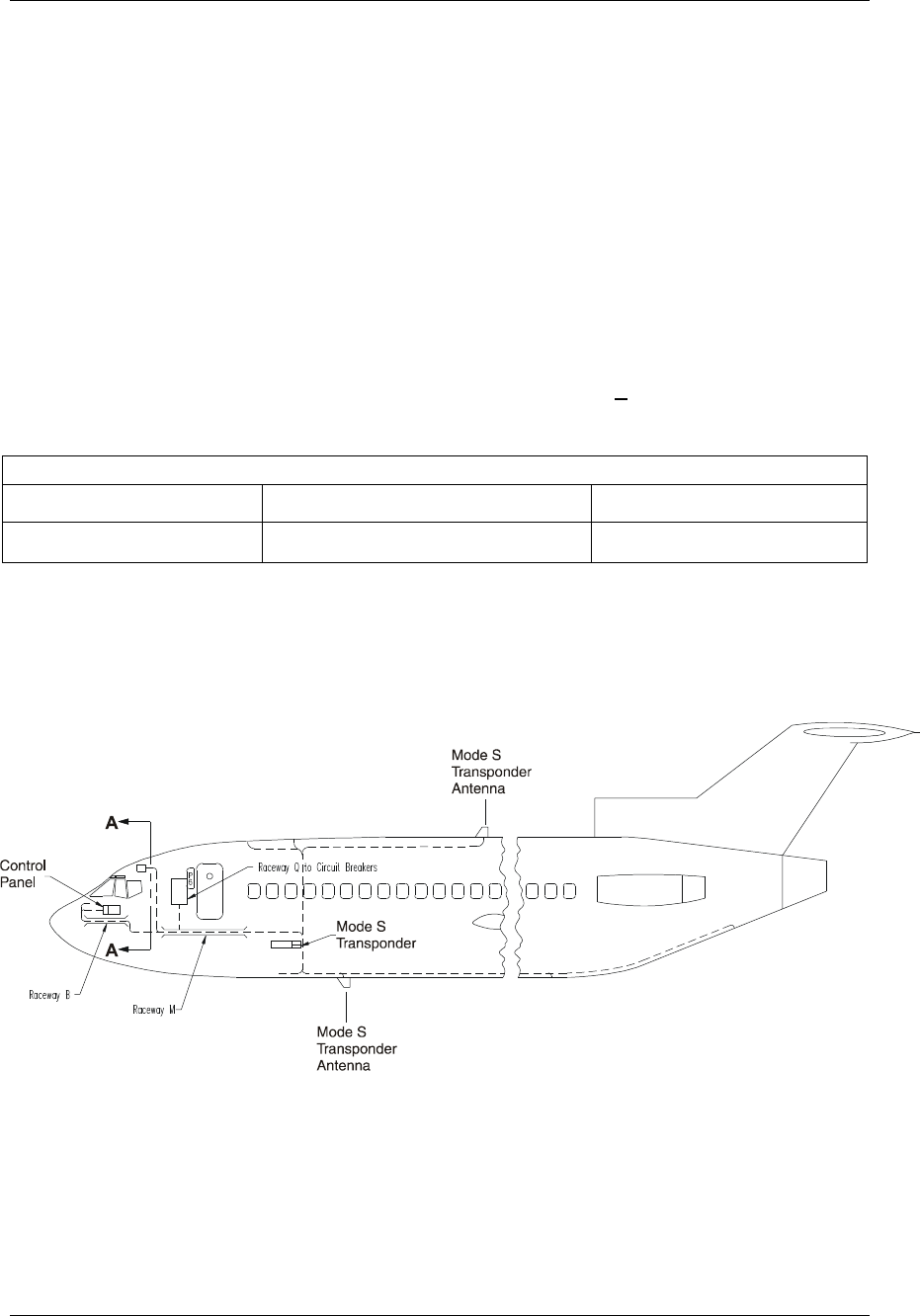
Figure 3 – Potential Equipment Locations
3.3.2 AT7000 Provisions
The AT7000 is mounted in a 4 MCU mounting tray per ARINC 600. See Figure 3.
Installation Installation Manual
Page 12 560-0405-00 Rev –
December 14, 2001
© 2001 by UPS Aviation Technologies Inc.
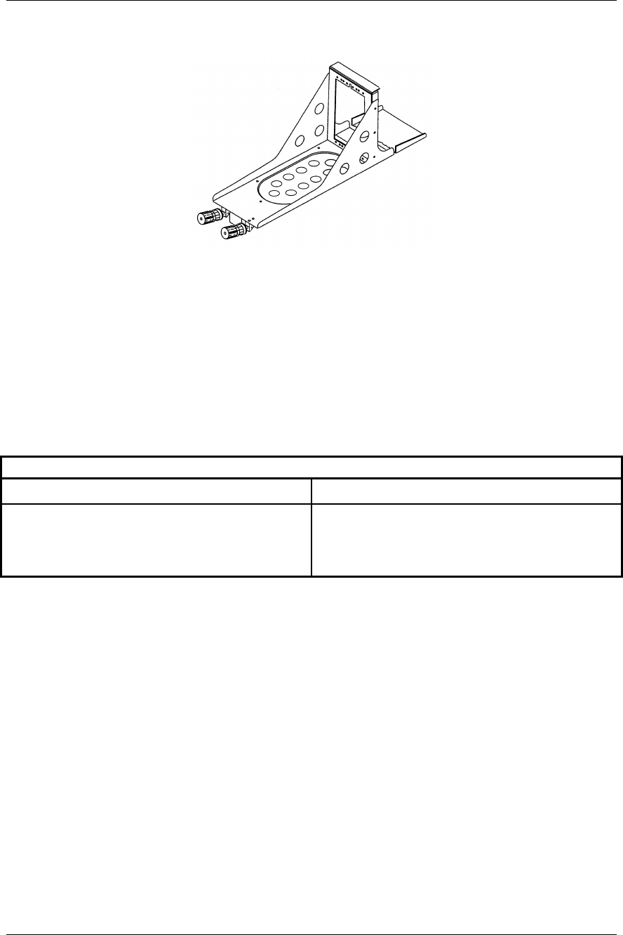
3.3.2.1 Mounting Tray
Figure 4 - ARINC 600 4 MCU Mounting Tray
3.3.3 Antenna Provisions
Install antenna in accordance with manufacturer specifications.
Sealant should be applied as required to the antenna base to prevent leakage of water and
condensation while also preventing corrosion. Any sealant or aerodynamic smoother used
around the edge of the antenna base must be applied only after the antenna has been
bolted and secured to the aircraft. Each antenna should have a maximum of 2.5 milli-ohm
ground bond resistance.
Table 2 - Antenna Minimum Spacing
Antenna Minimum Spacing
DM-N150-2 (Dorne-Margolin P/N)
S65-5366-7L (Sensor Systems P/N)
Or equivalent L-Band Antenna
20” from other L-band antennas in same
range.

Installation Manual Installation
560-0405-00 Rev –
December 14, 2001 Page 13
© 2001 by UPS Aviation Technologies Inc.
3.4 Electrical Installation
Reference
Section Signal Name Pin No. Equipment Connection
3.5.2
Gillham Code Altitude Input #2
A1
A2
A4
B1
B2
B4
C1
C2
C4
D2
TP 1A
TP 1B
TP 1C
TP 1D
TP 1E
TP 1F
TP 1G
TP 1H
TP 1J
TP 1K
*MSP Bus Input ARINC 429
A
B
TP 2A
TP 2B From Airborne Data Link Processor Unit (LDPU)
3.5.14
DAPS Input ARINC 429
A
B
TP 2C
TP 2D
Hardware Provisioned
Output ARINC 429
A
B
TP 2E
TP 2F
Reserved #1 Output ARINC 429
A
B
TP 2G
TP 2H
Reserved Discrete Input #1
TP 2J
3.5.2
Gillham Code Altitude Input #2
D4 TP 2K From Encoding Altimeter #2
Reserved Discrete Output
TP 3A
3.5.11.2
Transponder Fail Output #2
TP 3B To Mode S Control Panel J1-12
3.4.6
Antenna Cable Delay Program
Top/Bot
B
A
Common
TP 3C
TP 3D
TP 3E
TP 3F
3.4.4
SDI Program
B
A
Common
TP 3G
TP 3H
TP 3J
3.5.2
Gillham Code Altitude Input #2
Common TP 3K
3.5.3
Synchro Altitude Input #1
X course
Y course
Z course
Ref H
Ref C
X fine
Y fine
Z fine
flag
TP 4A
TP 4B
TP 4C
TP 4D
TP 4E
TP 4F
TP 4G
TP 4H
TP 4J
From Air Data Computer #1
*Optional
Figure 5 – Top Plug Interconnect Description (Sheet 1)

Installation Installation Manual
Page 14 560-0405-00 Rev –
December 14, 2001
© 2001 by UPS Aviation Technologies Inc.
Reference
Section Signal Name Pin No. Equipment Connection
3.4.5
Max Airspeed Program
A
B
C
COM
TP 5A
TP 5B
TP 5C
TP 5D
3.5.15
TX Coordination TCAS 429
A
B
TP 5E
TP 5F
To Pin 12D of TCAS Computer
To Pin 12E of TCAS Computer
3.5.15
XT Coordination TCAS 429
A
B
TP 5G
TP 5H
To Pin 14F of TCAS Computer
To Pin 14G of TCAS Computer
3.5.7
Air/Ground Discrete Inputs
#2
#1
TP 5J
TP 5K
To Air/Ground Relay
3.5.12
NAV Data/Flight ID 429 Input Bus
A
B
TP 6A
TP 6B From LDPU (ADLP)
Reserved
A
B
TP 6C
TP 6D
Reserved
A
B
TP 6E
TP 6F
Reserved
TP 6G
Reserved
A
B
TP 6H
TP 6J
3.4.7
Antenna Program
TP 6K
3.5.5
Control Panel Input Bus #1
A
B
TP 7A
TP 7B
To Pin 22 of Control Panel (Optional)
To Pin 23 of Control Panel (Optional)
Reserved
TP 7C
3.5.5.1
Control Panel Data Port Select
TP 7D
3.5.5
Control Panel Input Bus #2
A
B
TP 7E
TP 7F
To Pin 22 of Control Panel
To Pin 23 of Control Panel
3.5.6
Standby
TP 7G
3.5.4
Air Data #1 ARINC 429 Input
A
B
TP 7H
TP 7J To #1 Air Data Computer
Reserved
TP 7K
Figure 4 – Top Plug Interconnect Description (Sheet 2)
Installation Manual Installation
560-0405-00 Rev –
December 14, 2001 Page 15
© 2001 by UPS Aviation Technologies Inc.
Figure 6 –Top Plug Connector Layout
SDI
B A
Gillham Altitude Input #2
A1 A2 A4 B1 B2 B4 C1 C2 C4 D2
D4
ABCDEFGHJK
1
2
3
4
5
6
7
com
Data Link Input
A B
(429 ip)
RSVD #1 Output
A B
(429)
XPDR Fail
#2
(disc op)
Antenna Delay Program
comB ATop/Btm com
Synchro Altitude #1----------------------- Course ------------------
----
X Y Z
------------------------ Fine ---------------------
--
X Y ZH C
26VAC
Ref
Synchro
Flag #1
(disc ip)
RSVD
IP #2
(disc ip)
Max Airspeed Program
A B Ccom
TX COORD
A B
(429 ip)
XT COORD
A B
(429 pp)
Air/Gnd
#2
(disc ip)
Air/Gnd
#1
(disc ip)
Flight ID / FMS
A B
(429 ip)
ADL Input
A B
(429 ip)
ADL Output
A B
(429 op)
ADL IP
Sel
(disc ip)
Reserved
A B
Antenna
Program
(prgm ip)
Control Panel IP #1
A B
(429 ip)
RSVD
IP #3
(disc ip)
Cntl Pnl
Select
(disc ip)
Control Panel IP #2
A B
(429 ip)
Standby
(disc ip)
Air Data #1 Input
A B
(429 ip)
RSVD
IP #4
(disc ip)
Comm C/D Input
A B
(429 ip)
Comm C/D Output
A B
(429 op)
RSVD
IP #1
(disc ip)
RSVD
Output
(disc op)
Top Antenna
1-23-01 RAS
TP

Installation Installation Manual
Page 16 560-0405-00 Rev – December 14, 2001
© 2001 by UPS Aviation Technologies Inc.
THIS PAGE INTENTIONALLY LEFT BLANK

Installation Manual Installation
560-0405-00 Rev –
December 14, 2001 Page 17
© 2001 by UPS Aviation Technologies Inc.
3.4.1 Middle Plug
Reference
Section Signal Name Pin No. Equipment Connection
3.4.3.1
Reserved Mode S Address
Address 1
Address 2
Address 3
Address 4
Address 5
Address 6
Address 7
Address 8
Address 9
Address 10
Address 11
Address 12
Address 13
Address 14
Address 15
Address 16
Address 17
Address 18
Address 19
Address 20
Address 21
Address 22
Address 23
Address 24
Address Com
MP 1A
MP 1B
MP 1C
MP 1D
MP 1E
MP 1F
MP 1G
MP 1H
MP 1J
MP 1K
MP 2A
MP 2B
MP 2C
MP 2D
MP 2E
MP 2F
MP 2G
MP 2H
MP 2J
MP 2K
MP 3A
MP 3B
MP 3C
MP 3D
MP 3E
Reserved #1 ARINC 429 Input A
B
MP 3F
MP 3G
Reserved for mode control panel or other
DAPS inputs.
3.5.1.1 Functional Test Discrete Input MP 3H
3.5.10.2 Altitude Compare Fail Output MP 3J
3.5.11.1 XPDR Fail #1 Output MP 3K
3.5.2 Gillham Code Altitude Input #1
A1
A2
A4
B1
B2
B4
C1
C2
C4
D2
MP 4A
MP 4B
MP 4C
MP 4D
MP 4E
MP 4F
MP 4G
MP 4H
MP 4J
MP 4K
From Altimeter
3.5.4 Air Data #2 ARINC 429 Input A
B
MP 5A
MP 5B From #2 Air Data Computer
Reserved MP 5C
MP 5D Reserved for inputs for DAPS
Data Link 429 Output A
B
MP 5E
MP 5F MSP Bus to LDPU
Figure 7 – Middle Plug Interconnect Description (Sheet 1)

Installation Installation Manual
Page 18 560-0405-00 Rev –
December 14, 2001
© 2001 by UPS Aviation Technologies Inc.
Reference
Section Signal Name Pin No. Equipment Connection
3.5.10.1
Altitude Compare Input
MP 5G To Pin 17 of Control Panel
3.6
DL/DHL
Program Pin MP 5H
3.4.8
Antenna BITE Enable Program
Program Pin MP 5J
3.5.2
Gillham Code Altitude Input #1
D4 MP 5K
Maintenance Data 429 Input
A
B
MP 6A
MP 6B Hardware Provisions
Maintenance Data 429 Output
A
B
MP 6C
MP 6D Hardware Provisions
3.5.9
Altitude Input Source Selection
MP 6E To Pin 16 of Control Panel
3.4.9
Altitude Type Selection Program
B
A
COM
MP 6F
MP 6G
MP 6H
Reserved #2 ARINC 429 Input
MP 6J Tied to MP 7K
3.5.2
Gillham Code Altitude Input #1
COM MP 6K
3.5.3
Synchro Altitude Input #2
X Course
Y Course
Z Course
Ref H
Ref C
X Fine
Y Fine
Z Fine
Synchro #2
MP 7A
MP 7B
MP 7C
MP 7D
MP 7E
MP 7F
MP 7G
MP 7H
MP 7J Discrete Input
Reserved #2 IP 429
BMP 7K Tied to MP 6J
Figure 6 – Middle Plug Interconnect Description (Sheet 2)
Installation Manual Installation
560-0405-00 Rev –
December 14, 2001 Page 19
© 2001 by UPS Aviation Technologies Inc.
Figure 8 – Middle Plug Connector Layout
Mode S Address Input
12345678910
20
A B C D EFGHJK
1
2
3
4
5
6
7
Gillham Altitude Input #1
A1
Data Link Output
A B
(429 op)
Ant BITE
(prgrm ip)
Maint Data Input
A B
(429 ip)
Maint Data Output
A B
(429 op)
Synchro Altitude #2
X Y CX
Bottom Antenna
1-23-01 RAS
MP
11 12 13 14 15 16 17 18 19
21 22 23 24 com
Rsrvd #1 IP
A B
(429 ip)
Func Test
(disc ip)
Alt Cmpar
Fail
(disc op)
XPDR
Fail #1
(disc op)
A2 A4 B1 B2 B4 C1 C2 C4 D2
D4
com
Air Data #2
A B
(429 ip)
Reserved
A B
Alt Cmpar
En
(disc ip)
DL / DLP
(prgm ip)
Alt Src
Select
(disc ip)
Altitude Type Select
B A com
Rsrvd #2
429 IP
A
Rsrvd #2
429 IP
BZHYZ
26VAC
Ref
---------------------- Course --------------------- ------------------------ Fine -----------------------
Syncrho
Flag #2
(disc ip)

Installation Installation Manual
Page 20 560-0405-00 Rev – December 14, 2001
© 2001 by UPS Aviation Technologies Inc.
THIS PAGE INTENTIONALLY LEFT BLANK

Installation Manual Installation
560-0405-00 Rev –
December 14, 2001 Page 21
© 2001 by UPS Aviation Technologies Inc.
3.4.2 Bottom Plug
Signal Name Pin No. Equipment Connection
115 VAC Input HOT BP 1
Future Spare BP 2
28 VDC Input Return BP 3
Future Spare BP 4
Future Spare BP 5
Future Spare BP 6
115 VAC Input Return BP 7
Signal Ground BP 8
Future Spare BP 9
28 VDC BP 10
Chassis Ground BP 11
Suppression BP 12
Suppression BP 13
Figure 9 – Bottom Plug Interconnect Description
Installation Installation Manual
Page 22 560-0405-00 Rev –
December 14, 2001
© 2001 by UPS Aviation Technologies Inc.
Figure 10 – Bottom Plug Connector Layout
Bottom
Plug
12
Suppression
Pulse Input
13
(int. conx
to pin 12)
Suppression
Pulse Input
11
Chassis
Ground
(Aircraft DC
Ground)
9
Not Used
1
115 v AC
power input
Hot
2
Not Used
3
28VDC
Power Input
Return
(-)
7
115 vac
Power
Input
Return
8
Signal
Ground
(Aircraft DC
Ground)
6
Not Used
5
Not Used
4
Not Used
10
28 VDC
Power Input
(+)

Installation Manual Installation
560-0405-00 Rev –
December 14, 2001 Page 23
© 2001 by UPS Aviation Technologies Inc.
3.4.3 Program Pin Inputs
The transponder will require program pin connections defined by the particular installa-
tion. The transponder is programmed by connecting the appropriate input pins to com-
mon (ground) as defined in this section.
3.4.3.1 Mode S Address
The Mode S address is a unique 24-bit code assigned to each aircraft.
The 24-bit address is programmed by making the appropriate connections to the address
input pins. For each “1” bit in the address, connect the corresponding address input to the
address common pin (MP 3E), leave the pin open for a “0” bit.
Address 1 input (MP 1A) is the MSB (most significant bit) address, 24-input (MP 3D) is
the LSB (least significant bit). The address is normally defined as an eight character octal
code.
In the United States, the Mode S address can be obtained from:
Federal Aviation Administration
FAA Aircraft Registry
PO Box 25504
Oklahoma City, OK 73125
Telephone: (405) 954-3116
Fax: (405) 954-3548
3.4.4 SDI Program
The SDI program inputs are used to identify the transponder system number. The trans-
ponder number is made by connecting the defined SDI inputs to the SDI common pin (TP
3J) as follows:
Table 3 - SDI Program Pins
Transponder # SDI Prgm B
TP 3G
SDI Prgm A
TP 3H
Not Applicable Open Open
1Open Common
2Common Open
3Common Common
Common pin TP 3J
3.4.5 Max Airspeed Program
The maximum (max) airspeed program pins are used to identify the aircraft’s maximum
cruise airspeed capability. The maximum airspeed is programmed by connecting the
maximum airspeed program pins to the common pin (TP 5D) as follows:

Installation Installation Manual
Page 24 560-0405-00 Rev –
December 14, 2001
© 2001 by UPS Aviation Technologies Inc.
Table 4 - Max Airspeed Program
Max airspeed connections
Max Airspeed Prgm C
TP 5C
Prgm B
TP 5B
Prgm A
TP 5A
Not available Open Open Open
Up to 75 knots Open Open Common
75 to 150 knots Open Common Open
150 to 300 knots Open Common Common
300 to 600 knots Common Open Open
600 to 1200 knots Common Open Common
Above 1200 knots Common Common Open
Not assigned Common Common Common
Common pin TP 5D
3.4.6 Antenna Delay Program
The antenna cables from the transponder to the top and bottom antennas may vary in
length. The transponder must be programmed for the cable delay if the difference be-
tween the top and bottom antennas is greater than 50 nsec. This is accomplished by con-
necting the appropriate pins to the common pin as defined in the following table.
Table 5 - Antenna Delay Program
Delay Program Connections
Differential Delay (nsec) Delay B
TP 3D
Delay A
TP 3E
Programmed Delay
(nsec)
0 to 50 Open Open 0
51 to 150 Open Common 100
151 to 250 Common Open 200
251 to 350 Common Common 300
Open Common
TP 3C Add delay to top
antenna Add delay to
bottom antenna
Common Pin TP 3F
3.4.6.1 Antenna Delay Calculation
The antenna cable delay is defined as the round trip propagation delay between the trans-
ponder and the antenna. Typical cable delay is 1.54 nsec/ft.

Installation Manual Installation
560-0405-00 Rev –
December 14, 2001 Page 25
© 2001 by UPS Aviation Technologies Inc.
To compute the cable delay:
1. Calculate the difference in cable lengths between the top and bottom antennas in
feet.
2. Determine the cable delay: difference in length x 2 x 1.54 nsec/ft.
3. Select the coding and make the connections to the antenna delay program pins.
4. Select the top or bottom code: connect TP 3C to common if the top antenna coax is
longer than the bottom.
3.4.7 Antenna Program
This program pin is used to identify installations in which only the bottom antenna is
used.
Ground single bottom mount antenna installation
Open dual antenna installation
3.4.8 Antenna BITE Program
This program pin is used to enable the antenna BITE test. Antennas capable of the BITE
test will have a DC path to ground. If enabled, the transponder will perform a continuity
test to verify the antenna is connected.
Ground enable antenna BITE test
Open disable antenna BITE test
3.4.9 Altitude Type Selection
The transponder is capable of using altitude data from one of four types. The altitude type
used is programmed by making the connections as defined in the following table.
Table 6 - Altitude Type Selection
Program Pins
Data Source MP 6F MP 6G
429 Data Open Open
Synchro Data Open Common
Gillham Data Common Common
Common Pin MP 6H
3.5 Interface Connections
3.5.1 Discrete I/O Levels
3.5.1.1 Discrete Inputs
The discrete inputs have the following logic level thresholds:
Ground .................. < 3.5 volts DC or a resistance of < 10 ohms to ground
Open...................... > 18 volts DC or a resistance of > 100K to ground

Installation Installation Manual
Page 26 560-0405-00 Rev –
December 14, 2001
© 2001 by UPS Aviation Technologies Inc.
Series isolation diodes are included on all discrete inputs.
3.5.1.2 Discrete Outputs
The discrete outputs, unless otherwise defined, are open drain outputs. When active,
the output will be pulled low to ground. When inactive, the output be open (or pulled
high to 28 volts with 100K ohm).
Active.................... pulled low to ground
Inactive.................. open (100k pull-up)
3.5.1.3 Valid Flag Inputs
The valid flag inputs are intended for connection to valid superflag outputs on con-
nected equipment. The levels for these inputs are as follows:
Valid...................... > 18 volts DC input relative to ground
Invalid ................... < 3.5 volts DC input relative to ground
3.5.2 Gillham Code Altitude Input
The transponder allows connection to an altitude source using the 11 wire Gillham
code interface. Two inputs are provided, and the source can be selected with the alti-
tude source discrete input, see 3.5.9.
3.5.3 Synchro Altitude Input
The altitude information for the transponder may be obtained from an analog synchro
altitude interface.
3.5.3.1 Synchro Valid Flag Input
The synchro valid flag inputs are used to indicate the validity of the corresponding
synchro input. The transponder will not use the synchro altitude if the valid flag input
indicates an invalid condition. The synchro valid flag is a high level input.
3.5.4 ARINC 706 Air Data Inputs
The altitude information for the transponder may be obtained from an ARINC 706 air
data system via two low speed ARINC 429 data busses.
3.5.5 Control Panel Input
The control panel data may be entered into the transponder on either of two low speed
ARINC 429 data busses (Ports A and B). The port is selected by the control data port
select discrete input. See paragraph 3.5.5.1.
3.5.5.1 Control Panel Port Selection
The control port selection input is used to select which control panel port the trans-
ponder will use:
Ground ..................uses control panel port A
Open......................used control panel port B

Installation Manual Installation
560-0405-00 Rev –
December 14, 2001 Page 27
© 2001 by UPS Aviation Technologies Inc.
This input is a discrete input as defined in 3.5.1.1.
3.5.6 Standby Input
The standby discrete input is used to place the transponder in either the standby or ac-
tive modes and is normally connected to the transponder control panel. In the standby
mode, the transponder will not respond to any interrogations or generate squitters.
BITE will continue to operate in the standby mode. In the active mode, the trans-
ponder will respond to valid interrogations and generate squitters.
Ground ..................standby
Open......................active
This input is a discrete input as defined in 3.5.1.1.
3.5.7 Air/Ground Discrete Inputs
The air/ground discrete inputs are used by the transponder to determine air / ground
status of the aircraft. This is used to control or inhibit replies and to indicate whether
the aircraft is on the ground or airborne for Mode S replies.
3.5.7.1 Air/Ground #1
This input is used to not inhibit ATCRBS replies when on the ground, and is typically
used for ramp test functions so that the transponder can reply to all types of interroga-
tions.
Ground ..................aircraft on the ground
Open......................aircraft airborne
This input is a discrete input as defined in 3.5.1.1.
3.5.7.2 Air/Ground #2
This input is used to indicate that the aircraft is on the ground, and is normally con-
nected to the air/ground switch. When on the ground, the transponder will inhibit re-
plies to ATCRBS interrogations.
Ground ..................aircraft on the ground
Open......................aircraft airborne
This input is a discrete input as defined in 3.5.1.1.
3.5.8 Functional Test Discrete Input
The functional test input is used to place the transponder in a functional test mode.
Ground ..................enable functional test
Open......................normal operation
This input is a discrete input as defined in 3.5.1.1.

Installation Installation Manual
Page 28 560-0405-00 Rev –
December 14, 2001
© 2001 by UPS Aviation Technologies Inc.
3.5.9 Altitude Input Selection
This input is used to select the active port used for the altitude data input.
Ground ..................uses altitude input #2
Open......................uses altitude input #1
This input is a discrete input as defined in 3.5.1.1.
3.5.10 Altitude Compare
3.5.10.1 Altitude Compare Enable
The altitude compare enable discrete input is used to enable the altitude compare
function. Both altitude inputs must be valid. This feature works with Gillham, syn-
chro, or ADC inputs, as selected.
Ground .................. altitude compare enabled
Open...................... altitude compare inhibited
This input is a discrete input as defined in 3.5.1.1.
3.5.10.2 Altitude Compare Fail Output
The altitude fail discrete output is used to indicate invalid altitude input data, and is
normally connected to an indicator on the control panel.
Ground ..................valid data, or altitude compare normal
Open......................invalid, or altitude compare failure
The function of the altitude fail output is dependent on the altitude source selected as
follows:
Gillham data..........when the altitude compare is enabled, the output will indicate
failed when the two Gillham inputs are not within 500 feet
ARINC 429 data ...output will indicate failed when the ARINC 429 input is inva-
lid or ADC altitude inputs differ by more than 200 feet.
Synchro data..........output will indicate failed when the Synchro input is invalid
3.5.11 Transponder Fail Outputs
3.5.11.1 Transponder Fail Discrete Output #1
This output will supply 5 volts DC (capable of 25 mA) when the transponder has
failed, and will be open when the transponder is operating normally.
3.5.11.2 Transponder Fail Discrete Output #2
This output is open when the transponder has failed and is pulled low to ground when
the transponder is operating normally.
Valid...................... pulled low to ground
Failed..................... open

Installation Manual Installation
560-0405-00 Rev –
December 14, 2001 Page 29
© 2001 by UPS Aviation Technologies Inc.
This output is a discrete output as defined in 3.5.1.2.
3.5.12 Flight ID Input
The flight ID may be input to the transponder from multiple serial inputs, depending
upon installation requirements. The transponder will accept flight identification from any
of these inputs, which is contained within four ARINC 429 data words.
3.5.13 Data Link Interface
Four high speed ARINC 429 busses are provided for interfacing to a Mode S Airborne
Data Link Processor (ADLP). The input and output busses are used for transferring mes-
sages to and from the ADLP.
3.5.14 Downlinked Aircraft Parameters (DAPS)
The DAPS input busses and DAPS output busses are used for transferring aircraft spe-
cific parameters to the requesting ground station. Enabling this feature requires a soft-
ware upgrade. See ARINC 718A.
3.5.15 TX / XT Coord TCAS Interface
The TCAS/Transponder interface consists of two high-speed ARINC 429 busses. Inter-
face standards are listed in ARINC 735 and DO-185b. The transponder is operable with
both Collins and ACSS TCAS units.

Installation Installation Manual
Page 30 560-0405-00 Rev –
December 14, 2001
© 2001 by UPS Aviation Technologies Inc.
3.6 Data Loader Interface
Table 7 - Data Loader Plug
Reference
Section Signal Name Pin No. Equipment Connection
2.5
Portable Data Loader (PDL) ARINC 615 Input Bus
A
B
1
2
429 Input (Provisions Only)
429 Input (Provisions Only)
Spare
3
Spare
4
Chassis Ground (429 Input Bus Shield)
GND 5Shield Ground
Spare
6
Spare
7
PDL ARINC 615 Output Bus
A
B
8
9
429 Output (Provisions Only)
429 Output (Provisions Only)
Spare
10
Spare
11
Spare
12
Spare
13
Spare
14
Spare
15
Chassis Ground (429 Output Bus Shield)
GND 16 Shield Ground
Spare
17
Spare
18
Spare
19
115 Volt AC Power Input HOT
20
Chassis Ground
GND 21
115 Volt AC Power Input COMMON
22
Spare
23
Spare
24
Spare
25
Spare
26
Spare
27
Spare
28
Spare
29
Spare
30
Spare
31
Spare
32
Spare
33

Installation Manual Installation
560-0405-00 Rev –
December 14, 2001 Page 31
© 2001 by UPS Aviation Technologies Inc.
Table 7 - Data Loader Plug (Continued)
Reference
Section Signal Name Pin
No. Equipment Connection
Spare
34
Spare
35
Spare
36
28 Volt DC Power Input
POS 37
28 Volt DC Power Return
NEG 38
Spare
39
RS-232 Input
40 Maintenance Data/Software Update Port
RS-232 Output
41 Maintenance Data/Software Update Port
PDL CTS Input
42
PDL RTS Output
43
Spare
44
Spare
45
Spare
46
Spare
47
Chassis Ground
GND 48
Chassis Ground
GND 49
PDL Function Discrete
#1 50
PDL Function Discrete
#2 51
PDL Function Discrete
#3 52
PDL Function Discrete
#4 53

Installation Installation Manual
Page 32 560-0405-00 Rev –
December 14, 2001
© 2001 by UPS Aviation Technologies Inc.
VIEW OF MATING CONNECTOR ON AIRCRAFT
VIEW OF CONNECTOR ON UNIT
Figure 11 – Data Loader

Installation Manual Post-Installation Checkout
560-0405-00 Rev –
December 14, 2001 Page 33
© 2001 by UPS Aviation Technologies Inc.
Section 4 - Post-Installation Checkout
The Post Installation System Checkout verifies the wiring in the aircraft after installation.
The AT7000 includes Built-In Test Equipment (BITE) software functions. The BITE
software is used in the post-installation wiring checkout. The actual tests conducted will
be determined by the selected installation options.
4.1 Key Pin Orientation
Verify the key pin orientation on the ARINC connector is correct in the mounting tray.
Pin orientation is ARINC polarization index code 5. The view of the figure below is from
the back of the unit, and the dark areas are the solid part of the key. This is specifically
keyed for a Mark 3 transponder.
4.2 Pre-Installation Checkout Procedures
Prior to installing the equipment, perform power check as outlined below.
Power Check Transponder
115 VAC BP1 (see note below)
115 Return BP7
28 VDC BP10 (see note below)
28 Return BP 3
Note: The unit is able to accept either 28 VDC or 115 VAC.

Post-Installation Checkout Installation Manual
Page 34 560-0405-00 Rev –
December 14, 2001
© 2001 by UPS Aviation Technologies Inc.
NOTES

Installation Manual Equipment Removal and Replacement
560-0405-00 Rev –
December 14, 2001 Page 35
© 2001 by UPS Aviation Technologies Inc.
Section 5 - Equipment Removal and Re-
placement
5.1 Removal
5.1.1 Transponder
Remove the transponder from the tray with ARINC 600 hold-downs as follows:
1. Loosen unit hold-down knobs.
Figure 12 – Removal of Unit from Tray
2. Pull out and down to release the knob from the hook of component.
3. Slowly pull forward on unit handle to separate unit and tray connectors. Transponder
is now free to be removed from mounting tray. Place electrostatic protective covers
over transponder connector and aircraft mating electrical connector.
5.2 Replacement
5.2.1 Transponder
Replace the transponder in mounting tray as follows:
1. Remove protective plastic covers from aircraft connectors. Remove electrostatic
protective covers from transponder connectors.
2. Slide transponder into mounting tray.
CAUTION: DO NOT FORCE FIT. IF MATING IS DIFFICULT, REMOVE THE
TRANSPONDER AND CHECK FOR CONNECTOR PINS THAT
MAY BE BENT OR OUT OF ALIGNMENT. ALSO, CHECK THE
ALIGNMENT OF THE RECEPTACLE IN MOUNTING TRAY.

Equipment Removal and Replacement Installation Manual
Page 36 560-0405-00 Rev –
December 14, 2001
© 2001 by UPS Aviation Technologies Inc.
3. Carefully apply firm pressure until transponder connector is mated with connector
receptacle on mounting tray.
4. Pull knobs of mounting tray over hooks on the component and tighten unit hold-down
knobs, ensuring proper engagement is made.

Installation Manual Specifications
560-0405-00 Rev –
December 14, 2001 Page 37
© 2001 by UPS Aviation Technologies Inc.
Section 6 - Operation
The Mode S Data Link System can be configured in the following ways: two Mode S
Transponders or one Mode S Transponder and one ATCRBS Transponder. Single trans-
ponder installations are acceptable. The function of the Mode S System is to provide air
traffic information to Mode S and ATCRBS ground stations to aid in the air traffic con-
trol. The Mode S System receives ATCRBS interrogations (ground to air) and transmits
ATCRBS replies (air to ground); receives Mode S interrogations (ground to air) and
transmits Mode S replies (air to ground); receives TCAS interrogations (air to air) and
transmits Mode S replies (air to air).

Specifications Installation Manual
Page 38 560-0405-00 Rev –
December 14, 2001
© 2001 by UPS Aviation Technologies Inc.
NOTES

Installation Manual Specifications
560-0405-00 Rev –
December 14, 2001 Page 39
© 2001 by UPS Aviation Technologies Inc.
Section 7 - Specifications
This section includes detailed electrical, physical, environmental, and performance speci-
fications for the AT7000.
7.1 Electrical
Power Requirements (28VDC)
Operating Voltage ....................18 to 32.2VDC; 28 VDC typical
Power Consumption:
Standby Mode..........................................20 Watts
Active Mode (typical load)......................30 Watts
Active Mode (maximum load..................60 Watts
Power Requirements (115V, 400 Hz):
Operating Voltage.....................90 to 135VAC, 400 Hz; 115VAC, 400 Hz typical
Power Consumption:
Standby Mode..........................................24 Watts
Active Mode (typical load)......................36 Watts
Active Mode (maximum load..................65 Watts
7.2 Physical
ARINC 600 4MCU Type 2 Connector; (Polarization code “05”)
Height...................................................7.64"
Width....................................................5.04"
Depth ....................................................14.107"
AT7000 Weight ...................................9.6 lbs.

Specifications Installation Manual
Page 40 560-0405-00 Rev –
December 14, 2001
© 2001 by UPS Aviation Technologies Inc.
14.107”
5.04”
7.64”
Figure 13 – AT7000 Dimensions
7.3 Environmental
The AT7000 Mode S Transponder is designed and tested to meet appropriate categories
of RTCA/DO-xxx. The Environmental Qualification Form is included in Section 10.
Operating temperature...............................-20°C to +70°C
Storage temperature ..................................-55°C to +85°C
Temperature variation...............................5°C per minute (minimum)
Humidity ...................................................95% RH at 65°C for 6 hours (10 day cycle)
Maximum altitude.....................................55,000 feet
Cooling......................................................The unit can utilize external cooling air in
accordance with ARINC 600, ARINC 404
or operate in convection cooled environ-
ments.
7.4 Transponder Performance
TSO................................................................TSO-C112
TSO Class ......................................................CL 2A7, 121, 011
Warm-up ........................................................None required
Receiver Frequency........................................1030 MHz
Sensitivity (MTL) ..........................................-72 dBm +/- 1 dB
Dynamic Range..............................................>50 dB
Side Lobe Suppression...................................2 pulse (P1, P2), -60 dBm
Transmitter Frequency...................................1090 MHz +/- 120 kHz

Installation Manual Specifications
560-0405-00 Rev –
December 14, 2001 Page 41
© 2001 by UPS Aviation Technologies Inc.
Transmitter Power..........................................250 watts minimum, 400 watts typical, 600
watts maximum
Mode A Capability.........................................4096 codes plus SPI ident pulse
Mode C Capability.........................................-1000 to 126,700 feet, 100 foot increments.
Mode S Capability .........................................-1000 to 126,700 feet, 25 foot increments.

Specifications Installation Manual
Page 42 560-0405-00 Rev –
December 14, 2001
© 2001 by UPS Aviation Technologies Inc.
NOTES

Installation Manual Limitations
560-0405-00 Rev –
December 14, 2001 Page 43
© 2001 by UPS Aviation Technologies Inc.
Section 8 - Limitations
8.1 Installation
Installations are to be made in accordance with all appropriate FAA approved guidelines
for each given installation. It is the responsibility of the installer to ensure that aircraft
installation conditions meet the appropriate standards for the specific type and class and
operation of aircraft involved.

Limitations Installation Manual
Page 44 560-0405-00 Rev –
December 14, 2001
© 2001 by UPS Aviation Technologies Inc.
NOTES
Installation Manual Troubleshooting
560-0405-00 Rev –
December 14, 2001 Page 45
© 2001 by UPS Aviation Technologies Inc.
Section 9 - Troubleshooting
9.1 Introduction and Overview
9.1.1 Introduction
The AT7000 includes a status display located on the unit front panel which provides ad-
ditional information from the status LEDs. The display is used to display the mainte-
nance information. The four buttons located below the display are used to scroll through
the available display information.
The maintenance display includes an LED backlight. The backlight turns on when a but-
ton is pushed and remains on for five minutes after the last button is pressed.
9.1.2 Overview
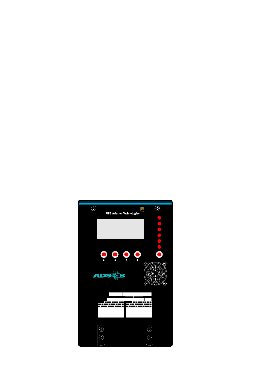
The AT7000 consists of the following interfaces for the user. On the front panel is a four
line by 16-character LCD display with backlight, five push buttons, and six status LEDs.
These interfaces are used to provide information useful for unit diagnostics, installation
checkout and verifying of aircraft interface inputs.
The maintenance display provides information about the unit, including: software version
number, system failure information, configuration pin inputs, discrete inputs, external
interfaces, and receiver/transmitter enable status.
Figure 14. AT7000 Mode S Transponder
MAINTENANCE DISPLAY
XPDR PASS
XPDR FAIL
CTRL PNL
ALT
TOP ANT
BOT ANT
TEST
DATA LOADER
AT7000
Mode S Data Link Transponder
barcode of serial number
SN '1234567'
UPS Aviation Technologies, Salem OR USA
Model:
AT7000
PN:
430-6091 - 00 - 00
SW Mod
TSO-C112 Class 2A7, 121, 011
RTCA/DO-178B Software Level B
RTCA/DO-160D Env. Cat.
FCC ID xxxxxxx
Mode S Transponder
C
AA
D
E
AB
AC
B
A
F
G
H
J
K
L
Z
Y
X
W
V
U
T
S
R
P
N
M
AD
AE
AF
AG
AH
AJ
AK
AL
AM
AN
HW Mod
C
AA
DE
AB
AC
BA FGHJKL
ZYXWVUTSRPNM
AD
AE
AF
AG
AH
AJ
AK
AL
AM
AN
Software
Map/Database
Weight
10.0 lbs.

Troubleshooting Installation Manual
Page 46 560-0405-00 Rev –
December 14, 2001
© 2001 by UPS Aviation Technologies Inc.
9.2 Interfaces
9.2.1 Buttons
The TEST button located under the front panel fault status LEDs is pushed to initiate the
‘Self Test’ and ‘Leg Fault’ status information.
The front panel buttons under the display are used for navigating display pages as fol-
lows:
← and → These buttons are used to select the column. When pressing one of these
buttons, the top page of either the previous (←) or next (→) group will be
displayed.
↑ and ↓These buttons are used to scroll through the pages within a column.
Pressing the ↑ button will move the previous page, the ↓ button will move
to the next page.
Note: The pages wrap around. The display is used only for displaying trans-
ponder information. No configuration or data can be input using the front
panel display and buttons.
9.2.2 Test Status LEDs
The AT7000 includes six test status LEDs on the front panel. These LEDs are used to
provide transponder test results and are generally used by aircraft mechanics. Failure
lights will stay illuminated for 3 seconds after powering up. Once in the self test mode
the fail light will stay illuminated for 10 seconds. When in this mode, pressing any but-
ton will illuminate the failure for 30 seconds.
Table 8 - Status LEDs Summary
LED Color Description
XPDR PASS Green Transponder pass, turned on if B.I.T.E. passes and the transponder is able
to operate.
XPDR FAIL Red Transponder fail, turned on if B.I.T.E. fails and the transponder is not able
to receive interrogations or generate replies.
CTRL PNL Red Control panel fail, turned on if the transponder is not receiving valid con-
trol information on the selected control panel ARINC 429 input port.
TOP ANT Red Top antenna fail, turned on if the top antenna B.I.T.E. test fails.
BOT ANT Red Bottom antenna fail, turned on if the bottom antenna B.I.T.E. test fails.
ALT Red Altitude fail, turned on if a valid altitude is not available from the selected
altitude input or if the altitude compare fails (when enabled).
9.2.3 Maintenance Display Pages
The diagram on the next page illustrates the operating modes and access matrix. The
software version page is displayed only once at power up and is only displayed until the
self-test starts.
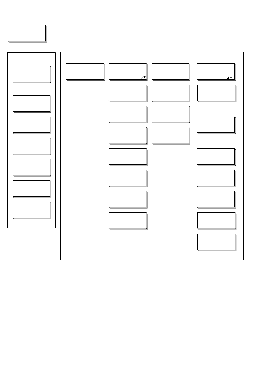
Installation Manual Troubleshooting
560-0405-00 Rev –
December 14, 2001 Page 47
© 2001 by UPS Aviation Technologies Inc.
Startup Display
SW Version
Self Test Status
PROGRAM
INPUTS
EXTERNAL
INTERFACES
Mode S Address
SDI Program
Max Airspeed
Altitude Type
Antenna Delay
Antenna BITE
Antenna Program
Self Test Mode Normal Mode
Gillham Altitude
Inputs*
Synchro
Altitude Inputs*
ADC (429)
Altitude Inputs*
Control Panel
Inputs
Flight ID Input
DataLink
Interface
TCAS Interface
Control Panel
Transponder
Fail Status
Control Panel
Fail Status
Top Antenna
Fail Status
Bottom Antenna
Fail Status
Altitude
Fail Status
(x2)
(x2)
(x2)
(x2)
UPS Aviation
Technologies
Power Up
DISCRETE
INPUTS
AT7000 Self
Test
Running
Altitude Select
Air/Ground
OR
OR
*Program Pin Dependent
*Program Pin Dependent
*Program Pin Dependent
Figure 15. Maintenance Displays
9.2.3.1 Page Descriptions
9.2.3.2 Display Functions
The front panel status display is used to display information useful for:
a. aircraft installation checkout
b. isolating aircraft system/wiring problems
c. displaying B.I.T.E. test results
d. transponder maintenance

Troubleshooting Installation Manual
Page 48 560-0405-00 Rev –
December 14, 2001
© 2001 by UPS Aviation Technologies Inc.
9.2.3.3 Startup Page
When the transponder is turned on, the following page is displayed for a moment (during
boot up), then the display changes to the ‘AT7000 Self Test Running’ display.
The start up display is used to display the unit model number and main application soft-
ware version.
9.2.3.4 Self Test Running Page
The AT7000 Self Test page is displayed for three seconds every time ‘Self Test’ mode is
initiated.
9.2.3.5 Self Test Status Pages
The ‘Self Test Status’ page displays the number of currently active fault types.
9.2.3.6 Flight Legs Fault Status Page
The ‘Flight Legs Fault Status’ page displays the number fault types for the leg defined as
current leg – 0 to 9. '0' being the current leg and '9' being nine legs prior to the current.
In the event an EEPROM log failure occurs, LOG FAILURE appears on the second line.
The log failure only pertains to the leg attempting to be viewed.
9.2.3.7 Transponder Fail Status
The Transponder Fail Status page is used to display the failure status of the transponder
when the transponder fail LED is turned on.
Trnspndr Failure
1) ICAO Address
2) Transmitter
3) Top Rcvr
UPS AVIATION
TECHNOLOGIES
AT7000 Mode S
SW Ver: 1.XX
AT7000 Self Test
Running
Self Test Result
0 Faults
Press TEST to
View Legs Info

Installation Manual Troubleshooting
560-0405-00 Rev –
December 14, 2001 Page 49
© 2001 by UPS Aviation Technologies Inc.
If internal failures are detected (causing the XPDR FAIL LED to illuminate), then the
cause of the failure will be displayed. Only one page will be displayed, with the three
most significant internal failures displayed.
a. ICAO Address
b. Internal component of Transponder
c. Top Transmitter
d. Bottom Transmitter
e. Tx Synth Lock
f. Rx Synth Lock
g. Top Receiver
h. Bottom Receiver
i. Squitter Mon
9.2.3.8 Control Panel Fail Status
This display is used to display the failure status of the selected control panel input if a
failure is detected and the control panel fail LED is illuminated.
The first line is used to display which of the control panels is selected, either A or B. The
failure is displayed on the second line, either “Invalid”, “Rate Failed”, or “No Data”.
For flight leg results all three faults can be displayed one per line starting on the second
line. Both Control Panel A and B pages can be displayed if failures occurred on each
while they were selected.
Control Panel A
No Data

Troubleshooting Installation Manual
Page 50 560-0405-00 Rev –
December 14, 2001
© 2001 by UPS Aviation Technologies Inc.
9.2.3.9 Top Antenna Fail Status
This display is used to display the top antenna BITE failure if a failure is detected and the
top antenna fail LED is illuminated.
9.2.3.10 Bottom Antenna Fail Status
This display is used to display the bottom antenna BITE failure if a failure is detected and
the bottom antenna fail LED is illuminated.
9.2.3.11 Altitude Fail Status
This display is used to display the altitude failure. The failure displayed is dependent
upon the selection of the altitude type program input.
The altitude source, either 1 or 2, is displayed on the first line.
The altitude type is displayed on the second line: ADC (429), Gillham, or Synchro.
The failure is displayed on the third line, depending on the type.
If ADC (429) is selected, then the failures will be “Invalid” or “No data”.
If Gillham is selected, then the failure will be “Invalid” if an invalid code is input, or
“Compare Fail” if the altitude compare is enabled and the compare fails.
If synchro is selected, then the failures will be “Invalid” if an invalid synchro or reference
input is detected or “Flagged” if the synchro flag input indicates an invalid condition.
For flight leg results all two faults can be displayed one per line starting on the second
line. Both Altitude Source 1 and Altitude Source 2 pages can be displayed if failures oc-
curred for each while they were selected.
Top Antenna
BITE Test Fail
Bottom Antenna
BITE Test Fail
Altitude SRC #1
Type: ADC (429)
Invalid

Installation Manual Troubleshooting
560-0405-00 Rev –
December 14, 2001 Page 51
© 2001 by UPS Aviation Technologies Inc.
9.2.4 Normal Mode
In normal mode the pages are intended for system checkout or fault isolation when the
aircraft is on the ground.
9.2.4.1 Default Page
The transponder will always return to the default page. This occurs when test mode times
out, or if any other page is displayed in Normal Mode and a button has not been pressed
in five minutes.
9.2.4.2 Program Inputs
The program inputs group is used to display the settings of each of the transponder’s rear
panel program inputs.
9.2.4.3 Mode S Address
This display is for decoding the 24-bit mode S address, displayed in octal and hexadeci-
mal.
PROGRAM INPUTS
PRESS ←→↑↓ TEST
UPS AVIATION TEC
H
-
NOLOGIES
AT7000 Mode S
PRESS ←→ or TEST
Mode S Address:
OCT 12345670
HEX 053977

Troubleshooting Installation Manual
Page 52 560-0405-00 Rev –
December 14, 2001
© 2001 by UPS Aviation Technologies Inc.
9.2.4.4 SDI Program Input
This display is SDI program input as 2 bits binary.
Possible numbers are 00, 01, 10 and 11.
If 00 is displayed, then also display “Invalid” on the bottom line.
9.2.4.5 Max Airspeed Program
This display is for the max airspeed program input.
The airspeed displays are:
0) invalid (0 is not available)
1) up to 75 knots
2) 75 to 150 knots
3) 150 to 300 knots
4) 300 to 600 knots
5) 600 to 1200 knots
6) above 1200 knots
7) invalid (7 is not assigned)
9.2.4.6 Altitude Type Program
This is used to display the current altitude input type selected by the program pin inputs.
The altitude selection displays are:
0) ADC (429) ARINC 429 air data input
1) Synchro
SDI Program:
00
Invalid
Altitude Type:
ADC (429)
Max Airspeed:
150 to 300 knots

Installation Manual Troubleshooting
560-0405-00 Rev –
December 14, 2001 Page 53
© 2001 by UPS Aviation Technologies Inc.
2) Gillham
3) Invalid
9.2.4.7 Antenna Delay Program
This display is for the antenna delay program input.
The delay selection displays are:
0) 0 to 50 nsec
1) 51 to 150 nsec
2) 151 to 250 nsec
3) 251 to 350 nsec
The antenna is either the bottom or top.
9.2.4.8 Antenna BITE Program
This page is for the antenna BITE program input.
The possible displayed antenna BITE selections are:
0) Disabled
1) Enabled
9.2.4.9 Antenna Program
This page displays the antenna program input.
Antenna Delay:
Delay:
51 to 150 nsec
Ant: bottom
Antenna BITE:
Enabled

Troubleshooting Installation Manual
Page 54 560-0405-00 Rev –
December 14, 2001
© 2001 by UPS Aviation Technologies Inc.
The antenna program selections are:
0) Dual antenna
1) Bottom only
9.2.5 Discrete Inputs
The Discrete Input group is used to display the status of the rear panel discrete inputs,
such as the altitude select and control panel select.
These displays are used to display the state of each of the discrete inputs, grouped in the
following pages.
Discrete Inputs Page 1:
The top line is used to display the control panel selected, either A or B.
The second line is used to display the current mode of the standby input, either “Standby”
or “Active”.
The third line is used to display the state of the functional test input, either “Test” or
“Norm”
Discrete Inputs Page 2:
The top line is used to display the altitude source selection, either 1 or 2.
Antenna Program:
Dual Antenna
DISCRETE INPUTS
Press ←→↑↓ TEST
Cntrl Panel:
A
Mode: Standby
Func Test: Test
Alt Select:
1
Alt Compare: on
Sync #1: Valid
Sync #2: Invalid

Installation Manual Troubleshooting
560-0405-00 Rev –
December 14, 2001 Page 55
© 2001 by UPS Aviation Technologies Inc.
The second line is used to display the state of the altitude compare input, either “on” or
“off”.
The third line is used to display the state of the synchro #1 valid flag input, either “valid”
or “Invalid”.
The fourth line is used to display the state of the synchro #2 valid flag input, either
“valid” or “Invalid”.
Discrete Inputs Page 3:
The top line is used to display the state of the air/ground #1 input, either “air” or “gnd”.
The second line is used to display the state of the air/ground #2 input, either “air” or
“gnd”.
9.2.6 External Interfaces
The external interfaces group is used to display the status of the rear panel interface in-
puts, such as the altitude and control panel inputs.
9.2.6.1 ADC Altitude Inputs
This page is used to display the altitude and status from the air data computer inputs.
The data is displayed for both the #1 and #2 inputs.
The altitude is displayed in feet, with 1 foot resolution.
The status of the input is displayed on the bottom line as:
• Valid
• Invalid (invalid status on 429 input data)
• No data (no 429 altitude input data)
Air/Gnd #1:
air
Air/Gnd #2: gnd
EXTERNAL INTE
R
-
FACES
Press ←→↑↓ TEST
429 Alt #1
15,475 feet
Valid

Troubleshooting Installation Manual
Page 56 560-0405-00 Rev –
December 14, 2001
© 2001 by UPS Aviation Technologies Inc.
Note: During aircraft ground maintenance operation, only the selected altitude input
needs to be displayed. During bench maintenance operation, all four altitude inputs will
be displayed.
9.2.6.2 Gillham Altitude Inputs
This page is used to display the altitude from the two Gillham altitude inputs.
The data is displayed for both the #1 and #2 inputs.
The altitude is displayed in feet, with a 100 foot resolution.
The status of the input is displayed on the bottom line as:
• Valid
• Invalid (for an invalid Gillham code input)
• Compare Fail (if the altitude compare is enabled and the compare fails)
9.2.6.3 Synchro Altitude Inputs
This page is used to display the altitude and status from the two synchro altitude inputs
The data is displayed for both the #1 and #2 inputs.
The altitude is displayed in feet, with a 1 foot resolution.
The status of the input is displayed on the 3rd line as:
• Valid
• Bad Ref (reference out of tolerance)
• Bad Input (XYZ inputs out of tolerance… sig level, …)
The status of the corresponding valid flag input is displayed on the bottom line as:
• Valid
• Invalid
Gillham Alt #1
15,500 feet
Valid
Synchro Alt #1
15,475 feet
Input: Valid
Flag: Valid

Installation Manual Troubleshooting
560-0405-00 Rev –
December 14, 2001 Page 57
© 2001 by UPS Aviation Technologies Inc.
9.2.6.4 Control Panel Inputs
These pages are used to display the info and status from the two control panel inputs.
The data is displayed for both A and B control panel inputs.
On the second line, the ident code displayed as four character octal, followed by “ident”
if SPI is enabled.
The operation mode is displayed on the third line as follows:
• Standby
• AltOff (active, altitude reporting is off)
• Active (active, altitude reporting is enabled)
• NotSelected
The status of the input is displayed on the bottom line as:
• Valid
• Invalid (invalid status on the 429 input data)
• No data (no 429 control panel data)
9.2.6.5 Flight ID Input
This page is used to display the status of the flight ID input.
The third line is used to display the current setting of the input:
• Flight ID (if the input is set to the flight ID function)
• Nav Data (if the input is set to the Nav data input function)
The status of the input is displayed on the bottom line as:
• Valid
• Invalid (invalid status on the input data)
• No data (no input data)
Control Panel
A
Ident: 1200ident
Mode: Active
Valid
Flight ID Input
Flight ID
Valid

Troubleshooting Installation Manual
Page 58 560-0405-00 Rev –
December 14, 2001
© 2001 by UPS Aviation Technologies Inc.
9.2.6.6 DataLink Interface
This page is used to display the status of the ARINC 429 data link interface.
The status of the input is displayed on the bottom line as:
• Valid
• Invalid (invalid status on the input data)
• No data (no input data)
9.2.6.7 TCAS Interface
This page is used to display the status of the ARINC 429 TCAS interface.
The third line is used to display the current setting of the input:
• Standby
• TA Only
• TA/RA
• TCAS IV
• (BLANK when No Data)
The status of the input is displayed on the bottom line as:
• Valid
• Invalid (invalid status on the input data)
• No data (no input data)
Datalink
Interface
Valid
TCAS Interface
Mode: Standby
Status: Valid

Installation Manual Troubleshooting
560-0405-00 Rev –
December 14, 2001 Page 59
© 2001 by UPS Aviation Technologies Inc.
9.3 Troubleshooting
The transponder has several system checks that can assist in troubleshooting. A self-test
can be conducted from the transponder front panel and from the control panel.
9.3.1 System Test
Before conducting this test, verify the following:
• Air data computer breaker(s) are closed and the unit(s) function
• Mode S transponder breaker is closed
• Transponder control panel breaker is closed
The table on the following page offers some troubleshooting information. The screens
are accessed in the ‘Self Test Mode’. To enter the ‘Self Test Mode’, at power up, press
the test button on the front panel. The start of ‘Self Test Mode’ turns all six front panel
lights ON for 3 seconds and displays the ‘Self Test Running’ page.
The panel lamps and display indicates the current faults until the test mode ends. Press-
ing the test button while in test mode displays faults beginning with current flight leg.
Subsequent presses of the test button cycles through the flight leg faults for up to ten
flight legs.
At the end of the ‘Self Test Mode’, the lamps all turn off and the user interface changes
to the normal mode.

Troubleshooting Installation Manual
Page 60 560-0405-00 Rev –
December 14, 2001
© 2001 by UPS Aviation Technologies Inc.
Table 9 - Troubleshooting Guide
Problem Cause Corrective Action
XPDR PASS LED is illumi-
nated. Normal operation. No action necessary.
XPDR FAIL LED is illumi-
nated. The ‘Trnspndr Failure’ page will show
up to three most significant failures:
1. ICAO Address
2. Internal component of Transponder
3. Top Transmitter
4. Bottom Transmitter
5. Tx Synth Lock
6. Rx Synth Lock
7. Top Receiver
8. Bottom Receiver
9. Squitter Mon
CTRL PNL failure light is il-
luminated and the ‘Control
Panel Fail Status’ page reads
‘Invalid’, ‘Rate Failed’ or ‘No
Data’.
Control panel not connected. Check wiring. Re-
place faulty control
panel.
TOP ANT failure light is illu-
minated and ‘Top Antenna’
page reads ‘BITE Test Fail’.
Top antenna not connected correctly.
BOT ANT failure light is il-
luminated and ‘Bottom An-
tenna’ page reads ‘BITE Test
Fail’.
Bottom antenna not connected correctly.
ALT SIG failure light is illu-
minated. The ‘Altitude Fail
Status’ will read ‘Invalid’ or
‘No Data’ if the type of alti-
tude source is ADC (429). If
Gillham is selected as the
source the display will read
‘Invalid’ or ‘Compare Fail’. If
Synchro is selected as the
source, the failures will be ‘In-
valid’ or ‘Flagged’.

Installation Manual Periodic Maintenance
560-0405-00 Rev –
December 14, 2001 Page 61
© 2001 by UPS Aviation Technologies Inc.
Section 10 - Periodic Maintenance
10.1 Maintenance
There are no internal manual adjustments needed.

Periodic Maintenance Installation Manual
Page 62 560-0405-00 Rev –
December 14, 2001
© 2001 by UPS Aviation Technologies Inc.
NOTES

Installation Manual Environmental Qualifications
560-0405-00 Rev –
December 14, 2001 Page 63
© 2001 by UPS Aviation Technologies Inc.
Section 11 - Environmental Qualifications
The AT7000 has been tested to the following environmental categories per procedures
defined in RTCA/DO-160D.
Table 10 - Environmental Requirements
Nomenclature: AT7000
Part No.: 430-6091-100
TSO No.: TSO C112
Manufacturer:
UPS Aviation Technologies
2345 Turner Road SE
Salem, Oregon 97302
Environment Section Category Comment
Temperature and Altitude 4A2 Operating Temp ............ -20°C to +70°C
Short Time Hi Temp ..... to +70°C
Cooling .........................Required
Ground survival temp ... -55°C to +85°C
Altitude ......................... 55,000 feet
Overpressure ................. –15,000 feet
Decompression ............. 55,000 feet
Temperature Variation 5BMinimum 5°C per minute
Humidity 6BSevere humidity environment.
Operational Shocks and Crash
Safety 7BTested for operational shock and crash safety.
Aircraft type 5, test type R
Vibration 8S & T S (curves B and M), T (curves B, B1 and R)
Explosion Proofness 9XNot applicable, no test required
Waterproofness 10 XNot applicable, no test required
Fluids Susceptibility 11 XNot applicable, no test required
Sand and Dust 12 XNot applicable, no test required
Fungus Resistance 13 XNot applicable, no test required
Salt Spray 14 XNot applicable, no test required
Magnetic Effect 15 Z< 0.3 meter
Power Input 16 A & E 28 volt DC and 115 volt 400 Hz AC
Voltage Spike 17 A
Audio Frequency Conducted Sus-
ceptibility - Power Inputs 18 A & E
Induced Signal Susceptibility 19 CZ is minimum requirement, C is the goal
Radio Frequency Susceptibility
(Radiated and Conducted) 20 VU is minimum requirement, V is the goal
Emission of Radio Frequency En-
ergy 21 M
Lightning Induced Transient Sus-
ceptibility 22 A3
C2
E2
Pin injection
Unshielded cables
Shielded cables
Lightning Direct Effects 23 XNot applicable, no test required
Icing 24 XNot applicable, no test required
Electrostatic Discharge (ESD) 25 A

Environmental Qualifications Installation Manual
Page 64 560-0405-00 Rev –
December 14, 2001
© 2001 by UPS Aviation Technologies Inc.
NOTES