Garmin AT COMM25-10 25 kHz VHF Comm User Manual SL40 Install 560 0956 03 Rev A
Garmin AT, Inc. 25 kHz VHF Comm SL40 Install 560 0956 03 Rev A
UserManual.wiki
>
Garmin AT
>
COMM25-10 User Manual
>
Installation Manual
Contents
1.
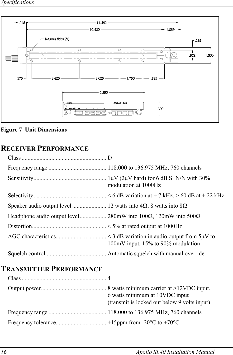
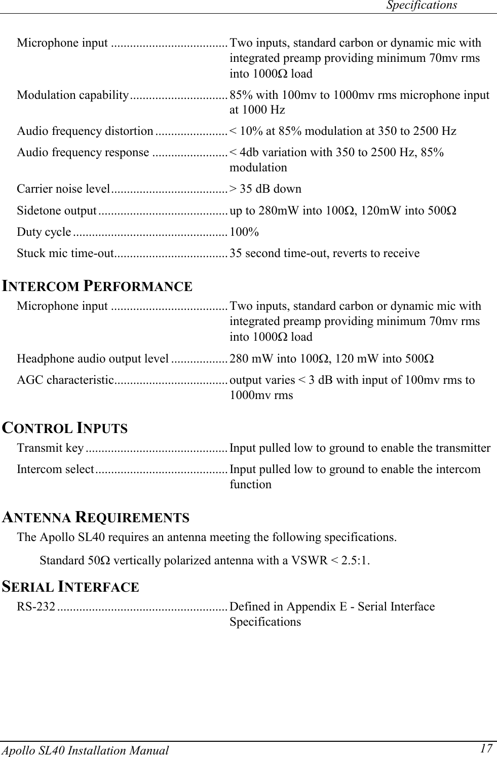
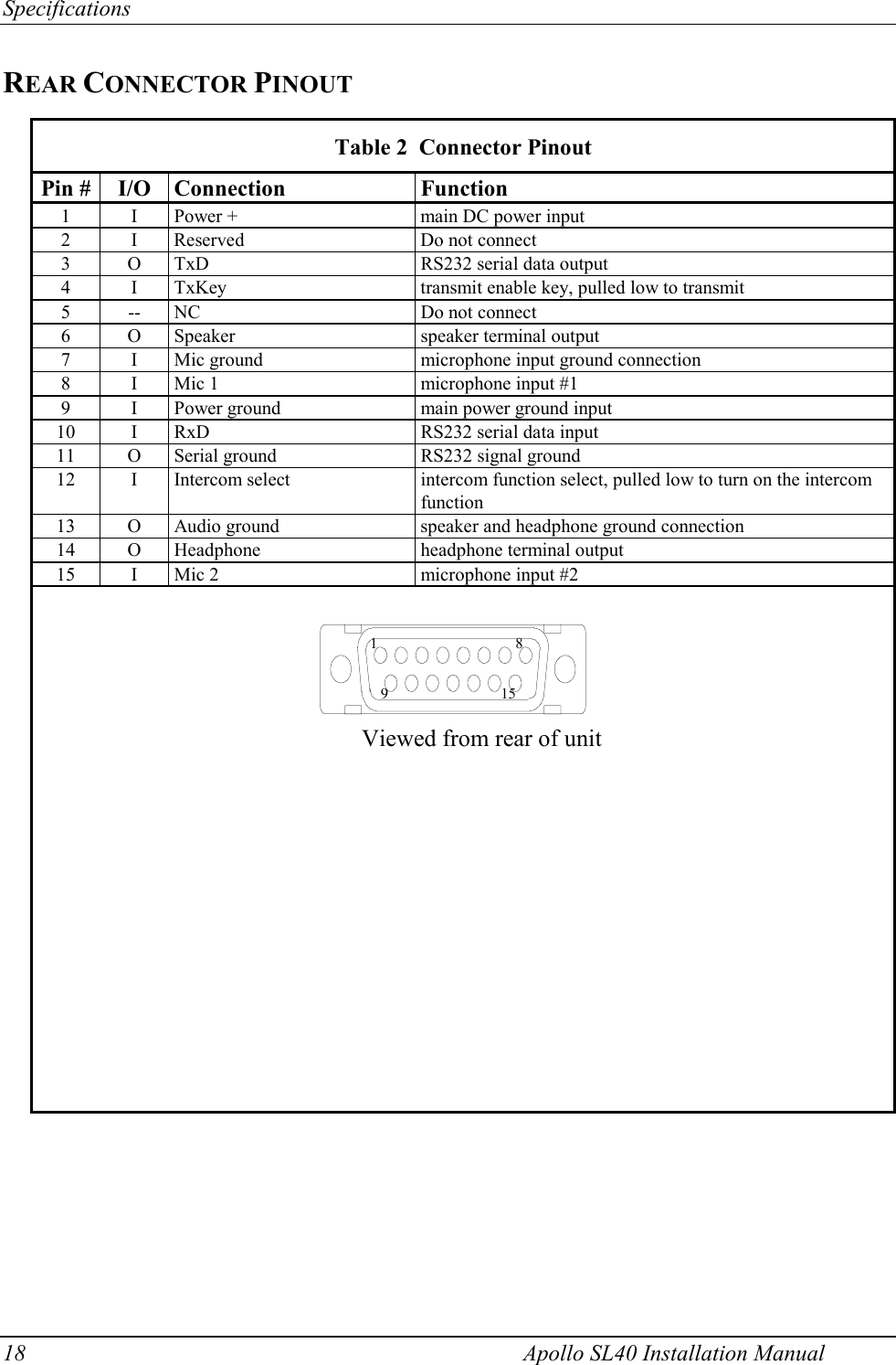
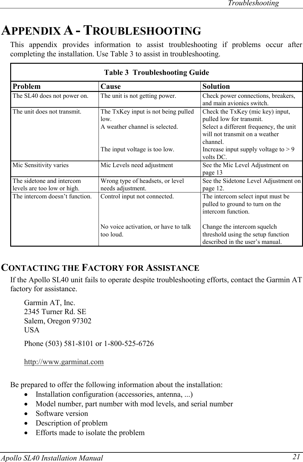
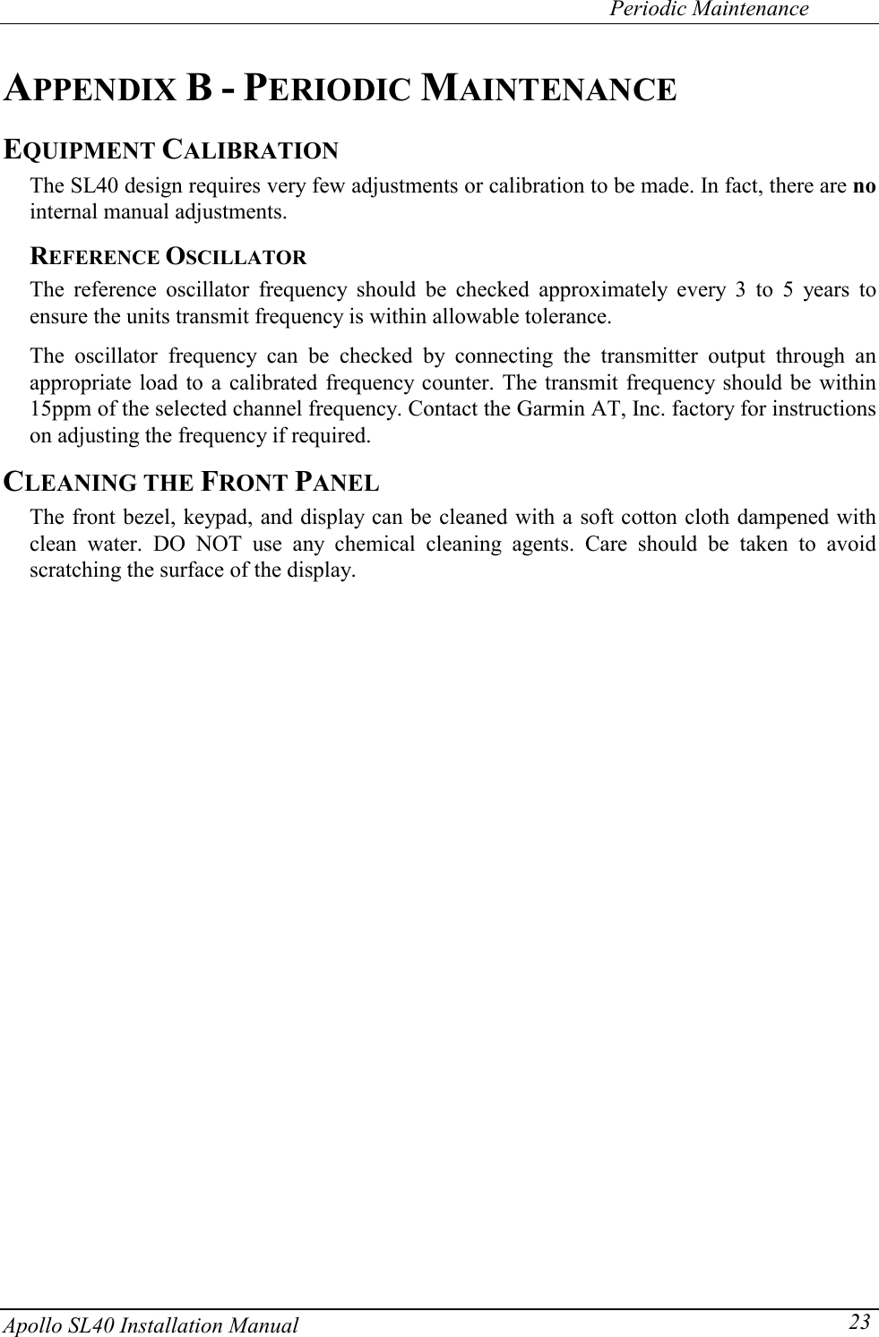
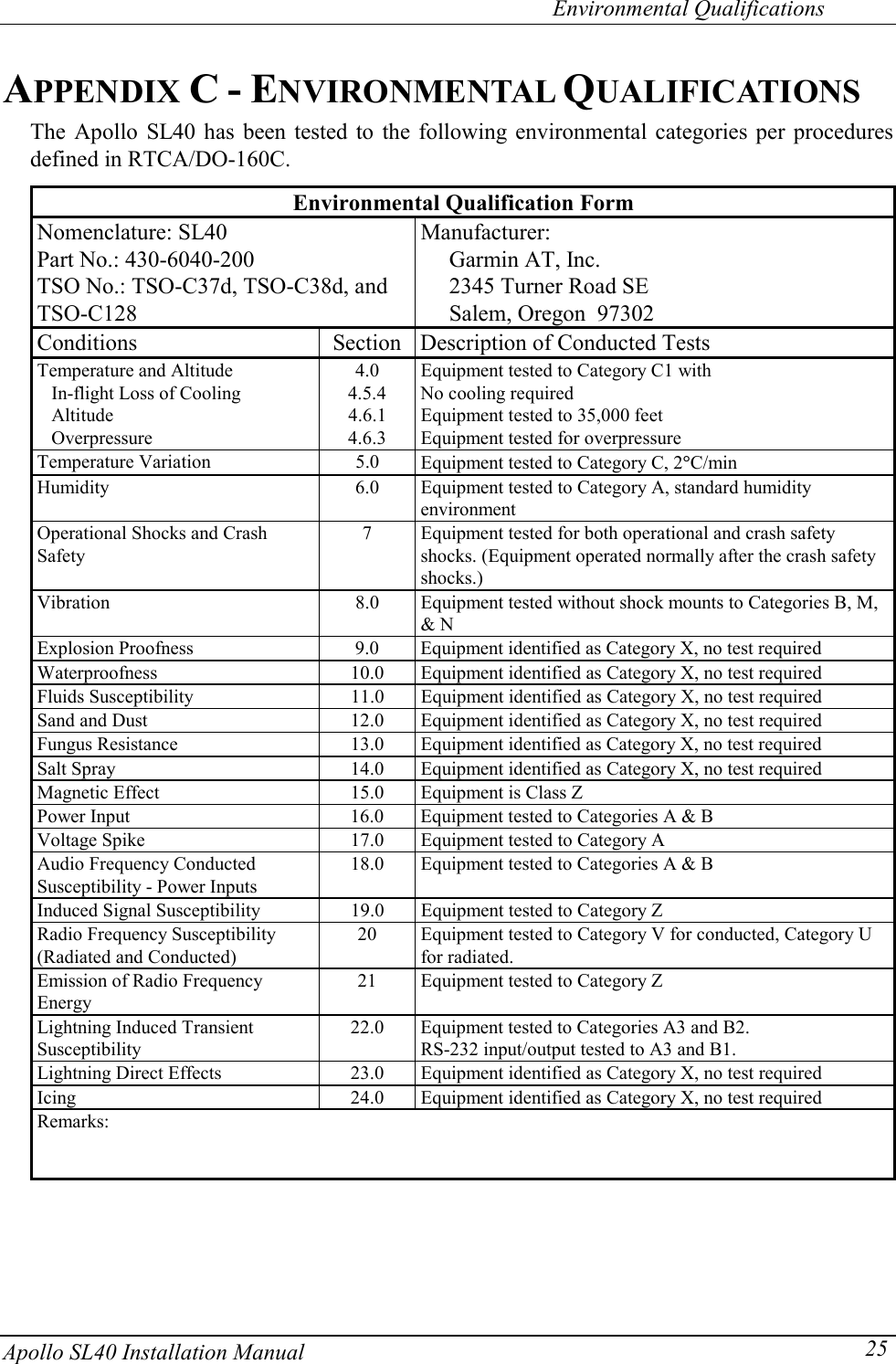
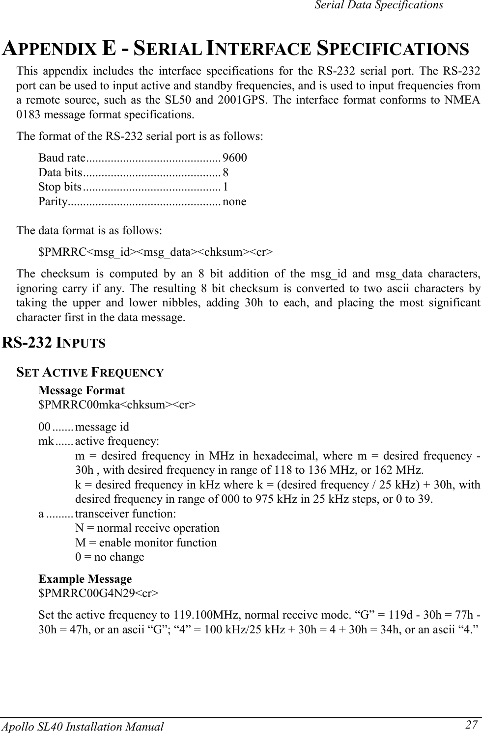
Installation Manual
2.
Users Guide
Installation Manual
Navigation menu
Upload a User Manual
Namespaces
Wiki Guide
HTML
PDF
Info
Views
User Manual
Discussion / Help
Navigation