Garmin AT GDL90A1H GDL 90 Universal Access Transceiver User Manual 560 1049 00 Rev B GDL90 Install Manual
Garmin AT, Inc. GDL 90 Universal Access Transceiver 560 1049 00 Rev B GDL90 Install Manual
UserManual.wiki
>
Garmin AT
>
GDL90A1H User Manual
Installation Manual
Navigation menu
Upload a User Manual
Namespaces
Wiki Guide
HTML
PDF
Info
Views
User Manual
Discussion / Help
Navigation
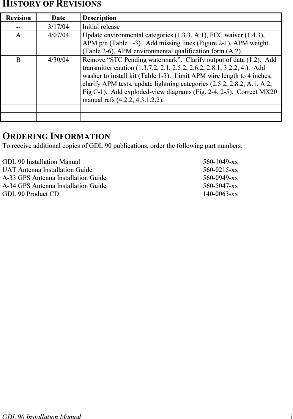
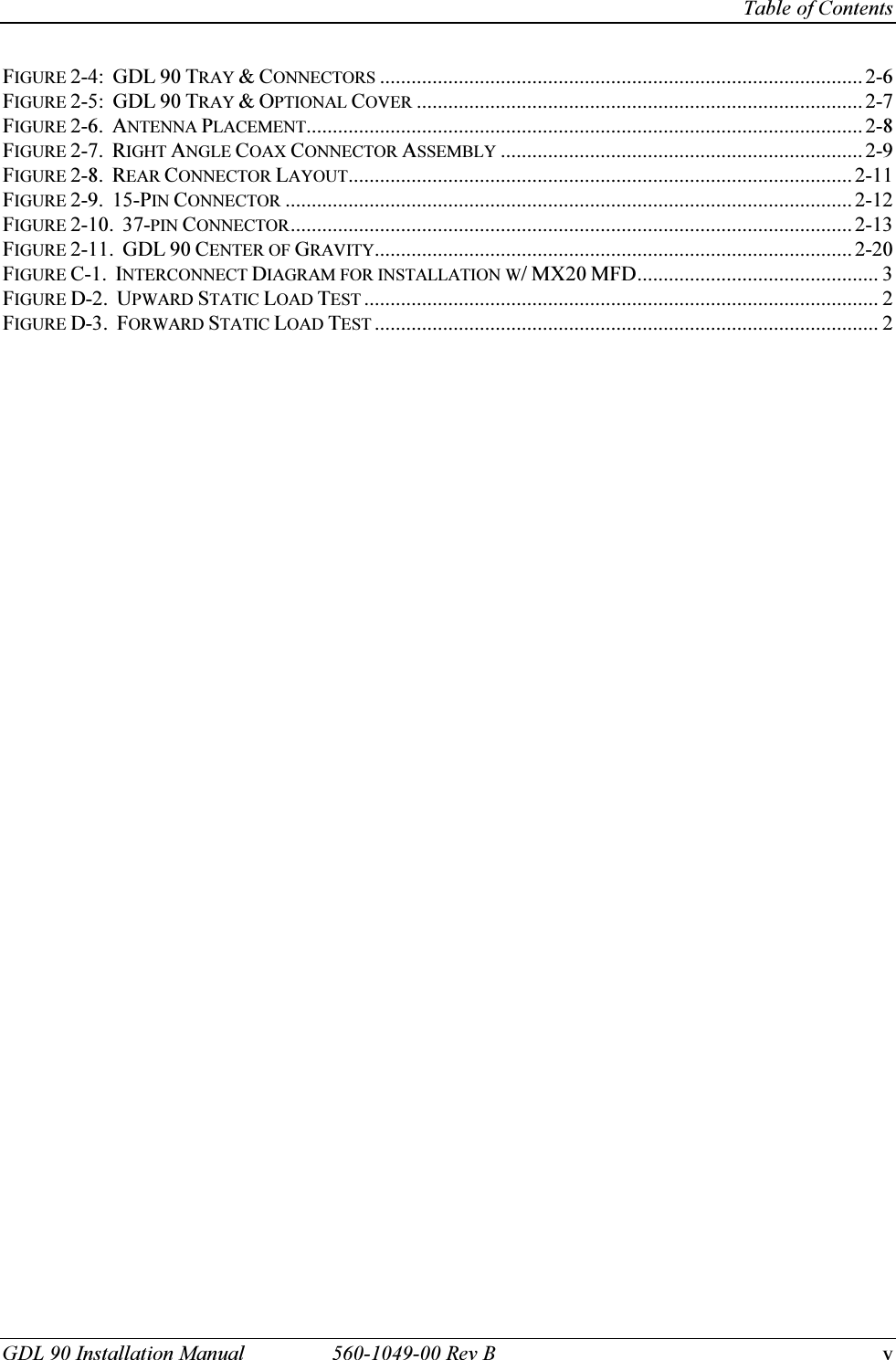
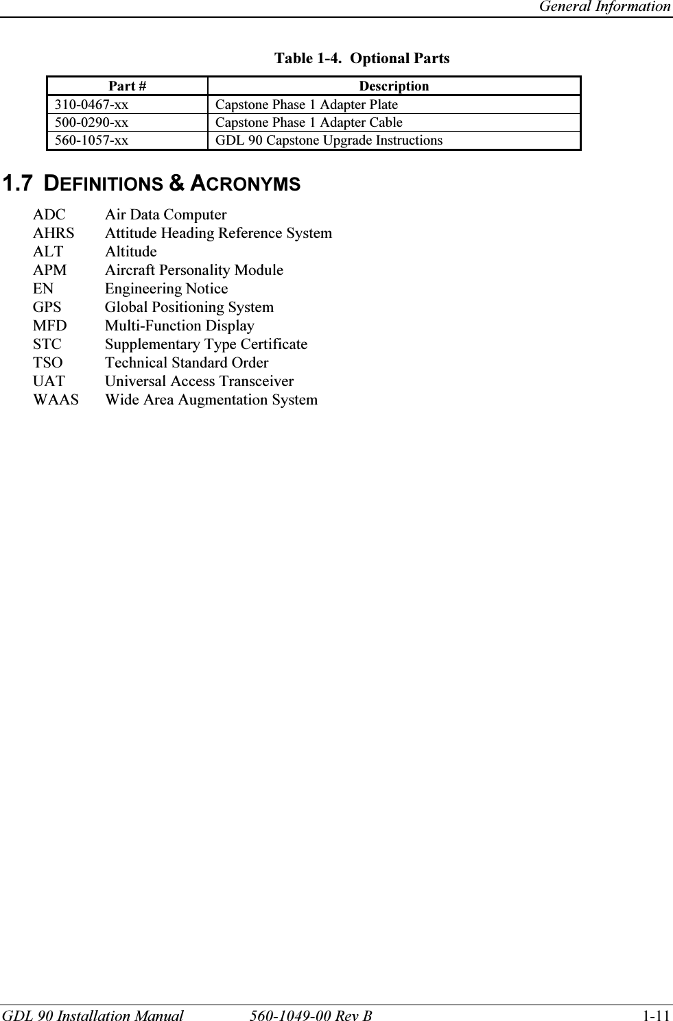
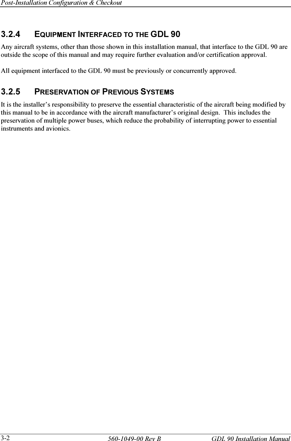
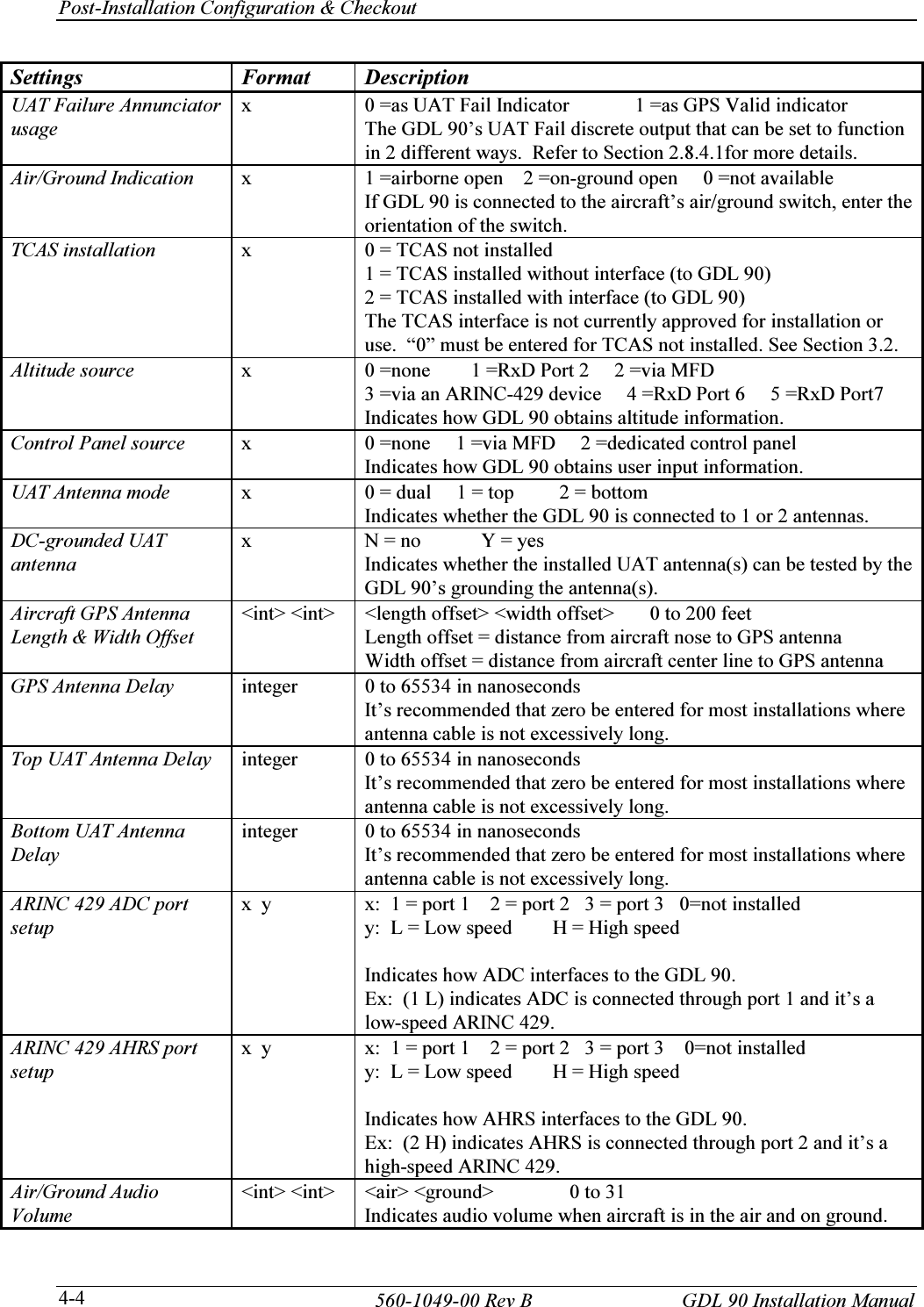
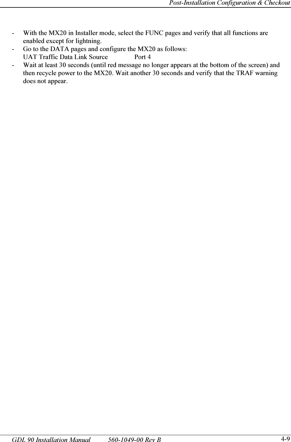
![Post-Installation Configuration & Checkout 560-1049-00 Rev B GDL 90 Installation Manual 4-8 3. Check the position using the GPSstatus command. The displayed lat/lon should agree with a known reference position. 4. Turn on other avionics one at a time and verify that the GPS LED remains steady on. 5. Check for VHF comm transmitter interference. NOTE The interference check must be completed on all IFR installations. a) Tune the Com 1 radio to 121.125 MHz. Listen on the frequency to ensure it is not in use, and then transmit for 30 seconds. b) While transmitting, observe the ‘GPS’ LED. Verify that the GPS LED remains steady on. If not, additional isolation measures will have to be taken. c) Repeat steps a) and b) for additional frequencies as follows. 121.150 MHz 131.225 MHz 121.175 MHz 131.250 MHz 121.185 MHz [1] 131.275 MHz 121.190 MHz [1] 130.285 MHz [1] 121.200 MHz 131.290 MHz [1] 121.225 MHz 131.300 MHz 121.250 MHz 131.325 MHz 131.200 MHz 131.350 MHz [1] frequency is only applicable to VHF radios with 8.33 kHz channel spacing d) Repeat for each com transmitter installed in the aircraft. e) If aircraft is TCAS-equipped, turn on the TCAS system and verify that GPS LED remains steady on. f) If aircraft is SATCOM-equipped, use the SATCOM system and verify that GPS LED remains steady on. g) If the GDL 90 is susceptible to VHF Com transmitter interference, then better isolation (or greater separation) may be required between the GPS and VHF (or other offending system) antennas. With some com transmitters, a 1575.42 MHz notch filter (such as Garmin AT P/N 162-1059) may be required in series with the VHF Com antenna coax at the rear of the com unit. ELT’s may re-radiate harmonics of the VHF Com signal into the GPS band. A 1575.42 MHz notch filter on the ELT will solve this. NOTE Older VHF Com transmitters may emit higher levels of harmonic interference. 4.3.1.2 Interface Checkout This section describes checks that can be carried out to verify that systems interfacing to the CNX80 are communicating properly. 4.3.1.2.1 Air Data Computer and Altitude Encoder Verify that the Ext LED on the front of the GDL 90 is not illuminated. 4.3.1.2.2 MX20 Display Checkout Refer to the MX20 installation manual (P/N 560-1025-08 or later FAA approved revision) for the following checks.](https://usermanual.wiki/Garmin-AT/GDL90A1H/User-Guide-445962-Page-52.png)
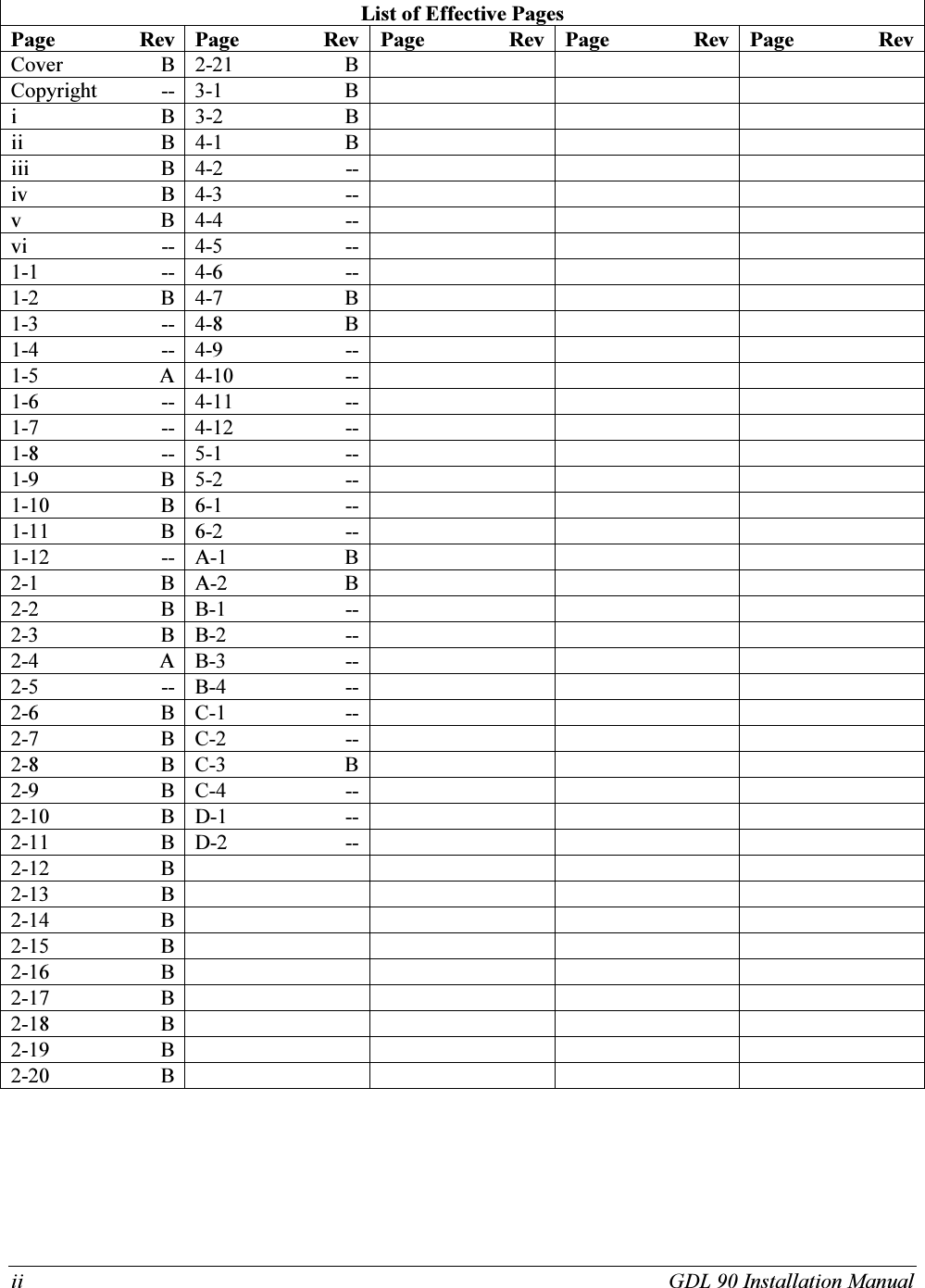
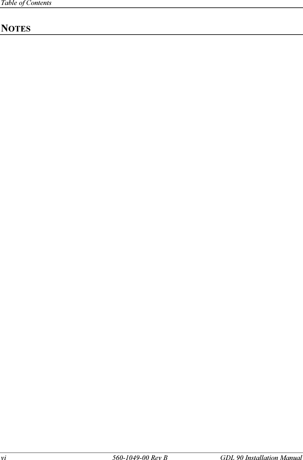
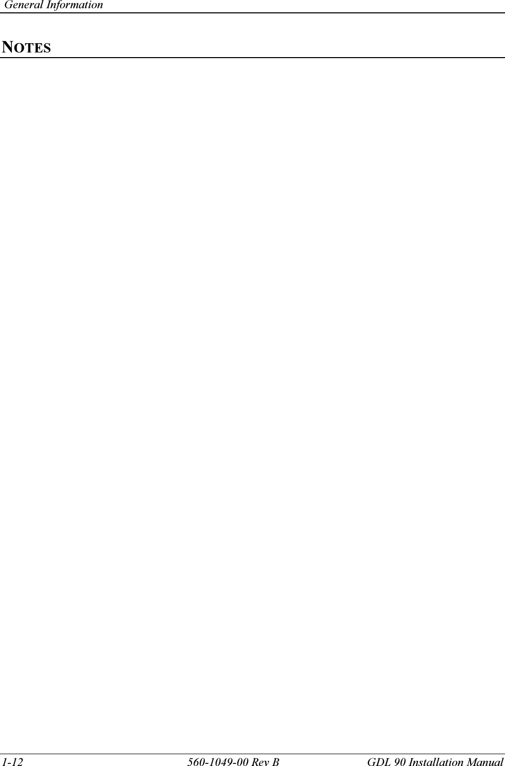
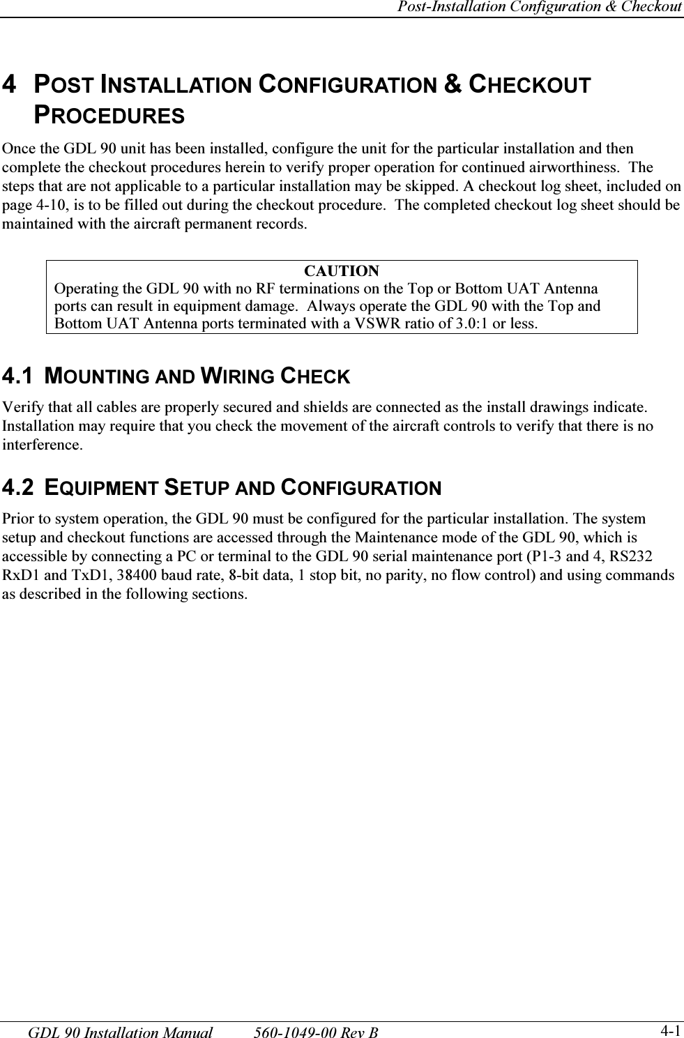
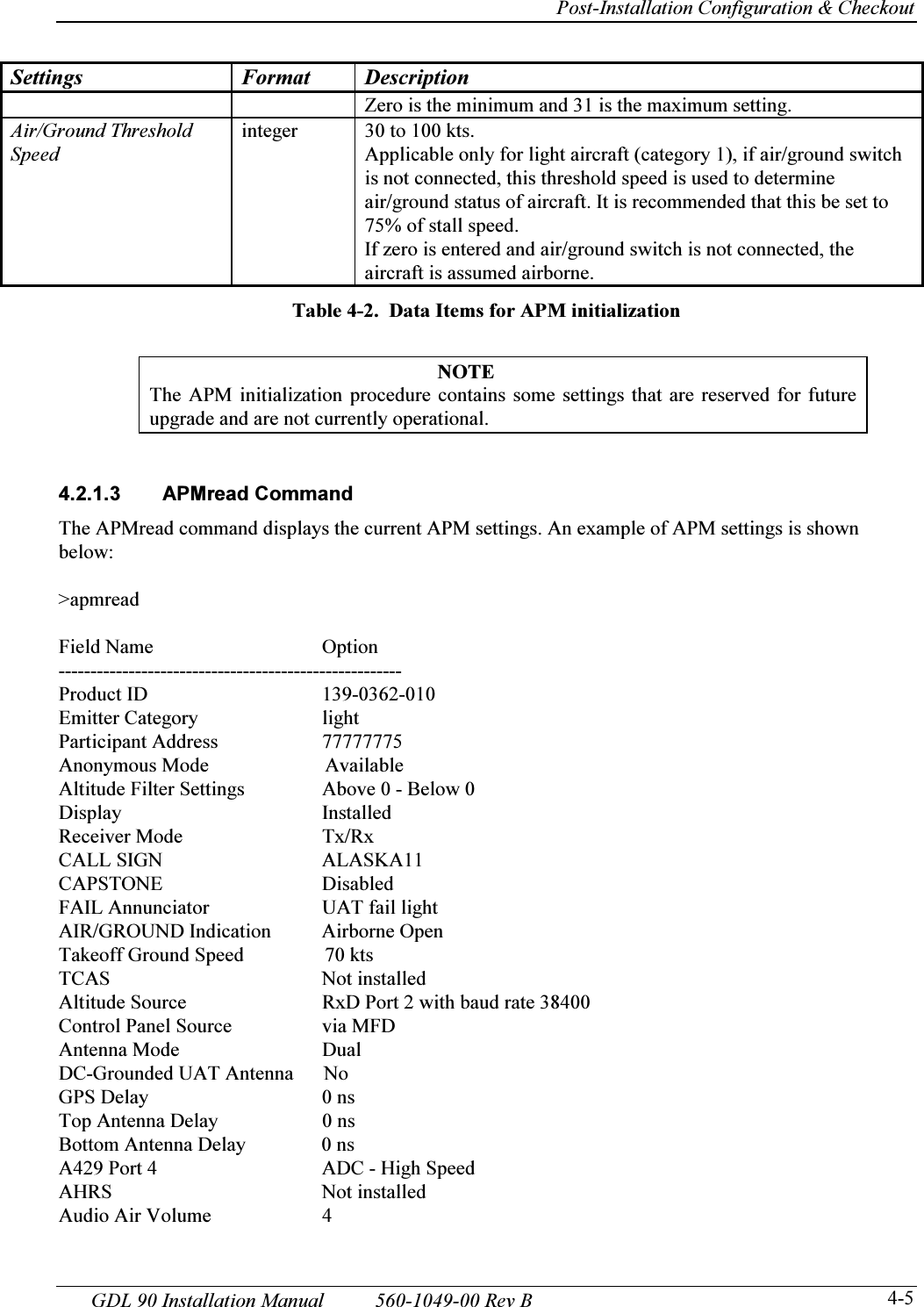
![Post-Installation Configuration & Checkout 560-1049-00 Rev B GDL 90 Installation Manual 4-10 Table 4-3. GDL 90 Post-Installation Checkout Log GDL 90 Post-Installation Checkout Log Date: ___/___/___ By: _____________ 430-6081-1_____-______ HW Mod ____ Serial # ___________ SW Mod ____ SETUP ITEMS: Serial Interface Configuration (RX/TX): ARINC 429 Input Configuration: Reserved for maintenance PC (Port 1) _____________ Hi Low (Channel 1 In) ______________/_____________ (Port 2) _____________ Hi Low (Channel 2 In) MX20 MFD interface (Port 3) _____________ Hi Low (Channel 3 In) ______________/_____________ (Rx Port 6) _____________ Hi Low (Channel 4 In) ______________/_____________ (Rx Port 7) ANNUNCIATOR OUTPUTS CHECKOUT: DISCRETE INPUTS CHECKOUT: UAT Fail Annunciator: [ N/A] Air / Ground Switch UAT Fail; GPS Indicator Suppression Out: connected to transponder GPS NAVIGATION CHECKOUT Position checked Interference from other avionics checked Signal reception checked VHF com interference checked INTERFACE CHECKOUT [ N/A] Transponder [ N/A] Altitude Encoder [ N/A] MX20 Display FLIGHT CHECKS: FINAL SYSTEM CHECK: COMMENTS:](https://usermanual.wiki/Garmin-AT/GDL90A1H/User-Guide-445962-Page-54.png)
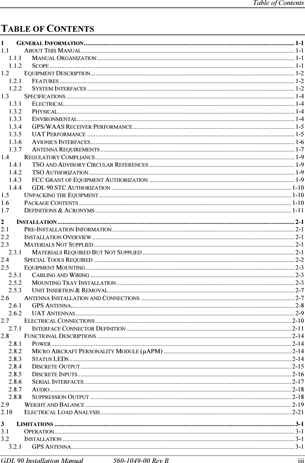
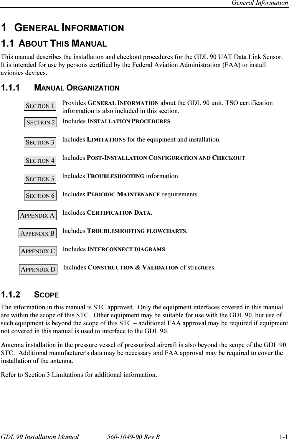
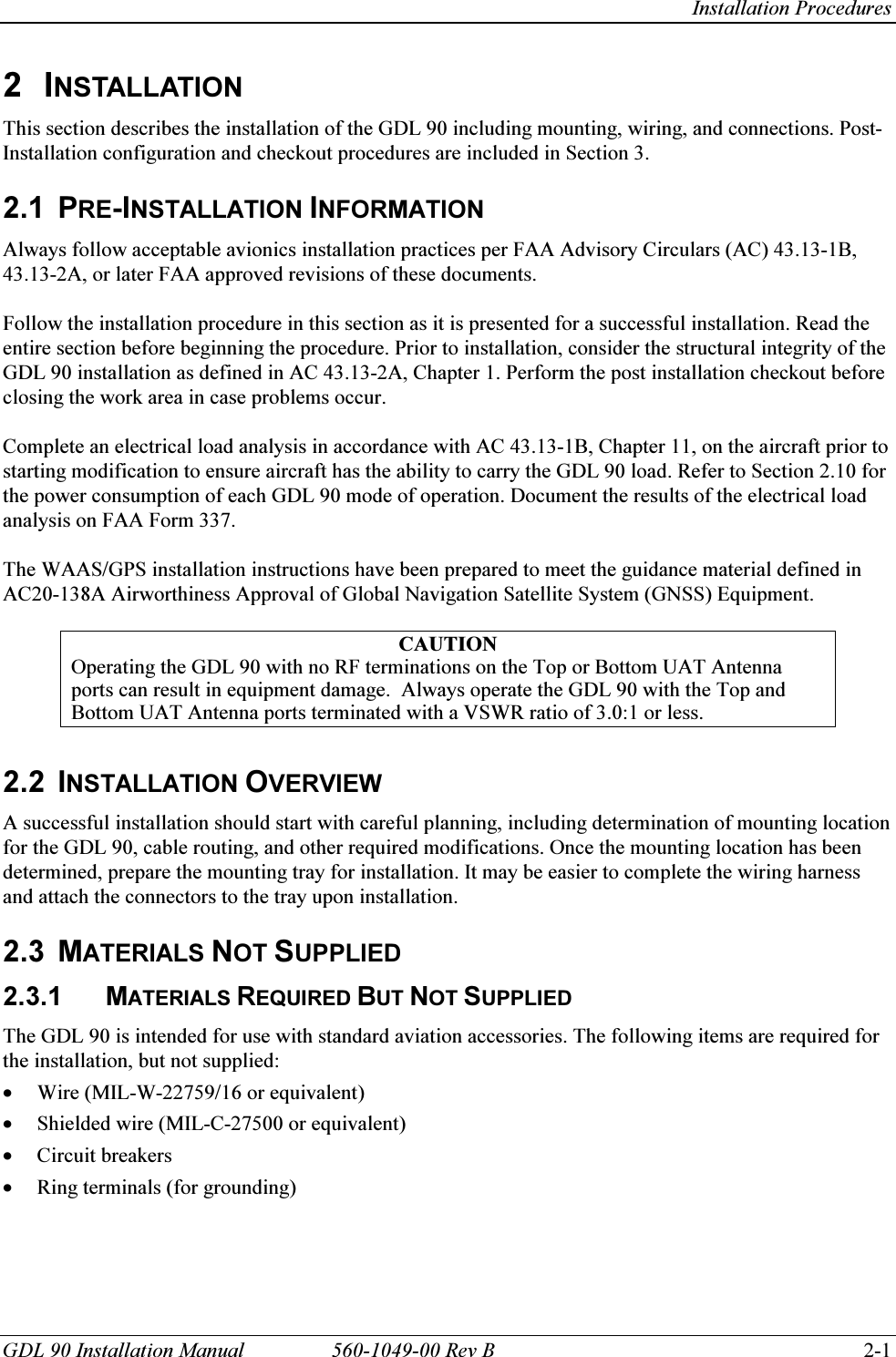
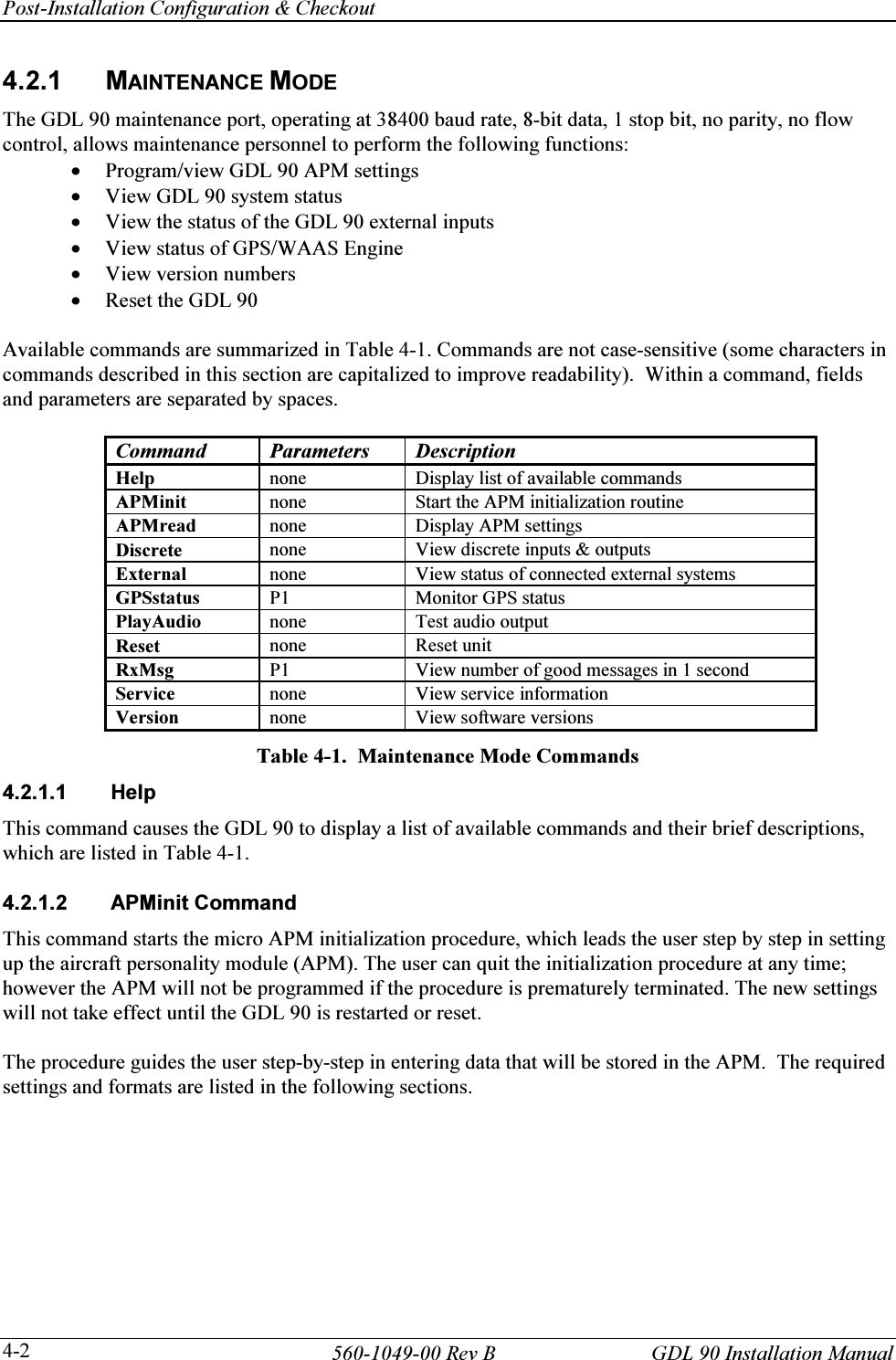
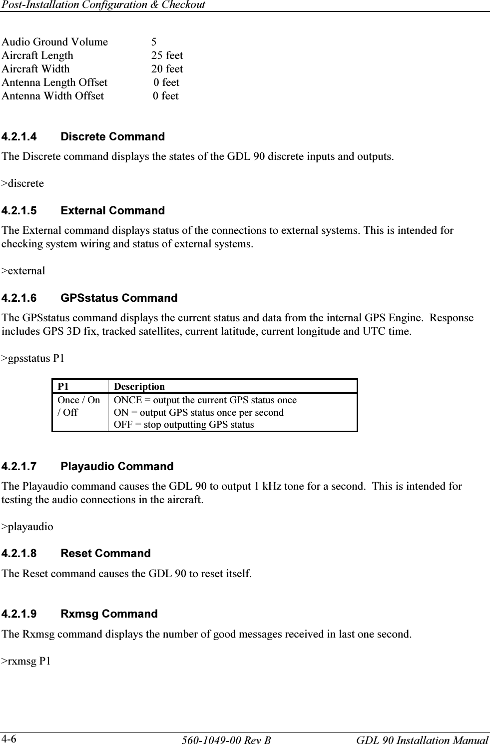
![Appendix A - Certification Data GDL 90 Installation Manual 560-1049-00 Rev B A-1 APPENDIX A - CERTIFICATION DATA A.1 GDL 90 ENVIRONMENTAL QUALIFICATION The GDL 90 has been tested to the following environmental categories per procedures defined in RTCA/DO-160D. Tests were conducted in February to April 2004 using the original 1997 revision of DO-160D and the specification defined in PD3536. Environmental Qualification Form Nomenclature: GDL 90 Part No.: 430-6081-1xx-xxx TSO No.: C145a, C154 Manufacturer: Garmin AT 2345 Turner Road SE Salem, Oregon 97302 Environment Section Category Comment Temperature and Altitude 4 F1 & A1 Operating temp ........ –20°C to +55°C Short time hi temp .... to +70°C Ground survival temp –55°C to +85°C Altitude .................... 55,000 feet Decompression 55,000 feet Overpressure Loss of cooling test -- not required No external cooling required provided internal fans are unobstructed and operating Temperature Variation 5 B Minimum 5°C per minute Humidity 6 B Severe humidity environment. Operational Shocks and Crash Safety 7 B5R meets operational and crash safety shock tests 20 Gs at 11 ms. Vibration 8 S(M & B) Standard vibration. Meets without shock mounts. Explosion Proofness 9 X not applicable, no test required Waterproofness 10 X not applicable, no test required Fluids Susceptibility 11 X not applicable, no test required Sand and Dust 12 X not applicable, no test required Fungus Resistance 13 X not applicable, no test required Salt Spray 14 X not applicable, no test required Magnetic Effect 15 Z < 0.3 meter Power Input 16 A & B for 28 and 14 volt systems Voltage Spike 17 A Audio Frequency Conducted Susceptibility - Power Inputs 18 Z Induced Signal Susceptibility 19 C Radio Frequency Susceptibility (Radiated and Conducted) 20 UV- [1] Equipment tested to Category U (Conducted) Equipment tested to Category V (Radiated) No Pulse tests performed. Emission of Radio Frequency Energy 21 M Lightning Induced Transient Susceptibility 22 A3XX Equipment tested to pin test waveform set A, level 3. No cable bundle test required. Lightning Direct Effects 23 X not applicable, no test required Icing 24 X not applicable, no test required Electrostatic Discharge (ESD) 25 A [1] The GDL 90 passes Category V (Radiated) for all TSO functions except temporary degraded receiver sensitivity at one frequency in the 2 to 3 GHz band.](https://usermanual.wiki/Garmin-AT/GDL90A1H/User-Guide-445962-Page-59.png)
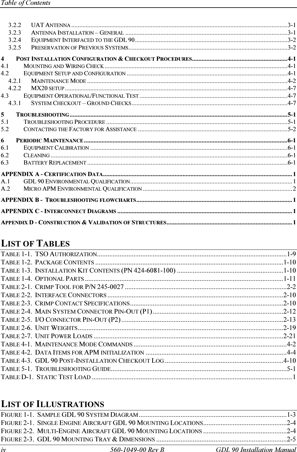
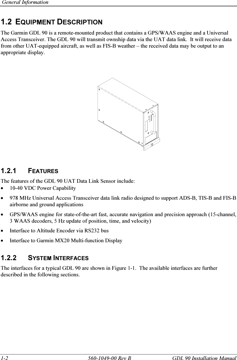
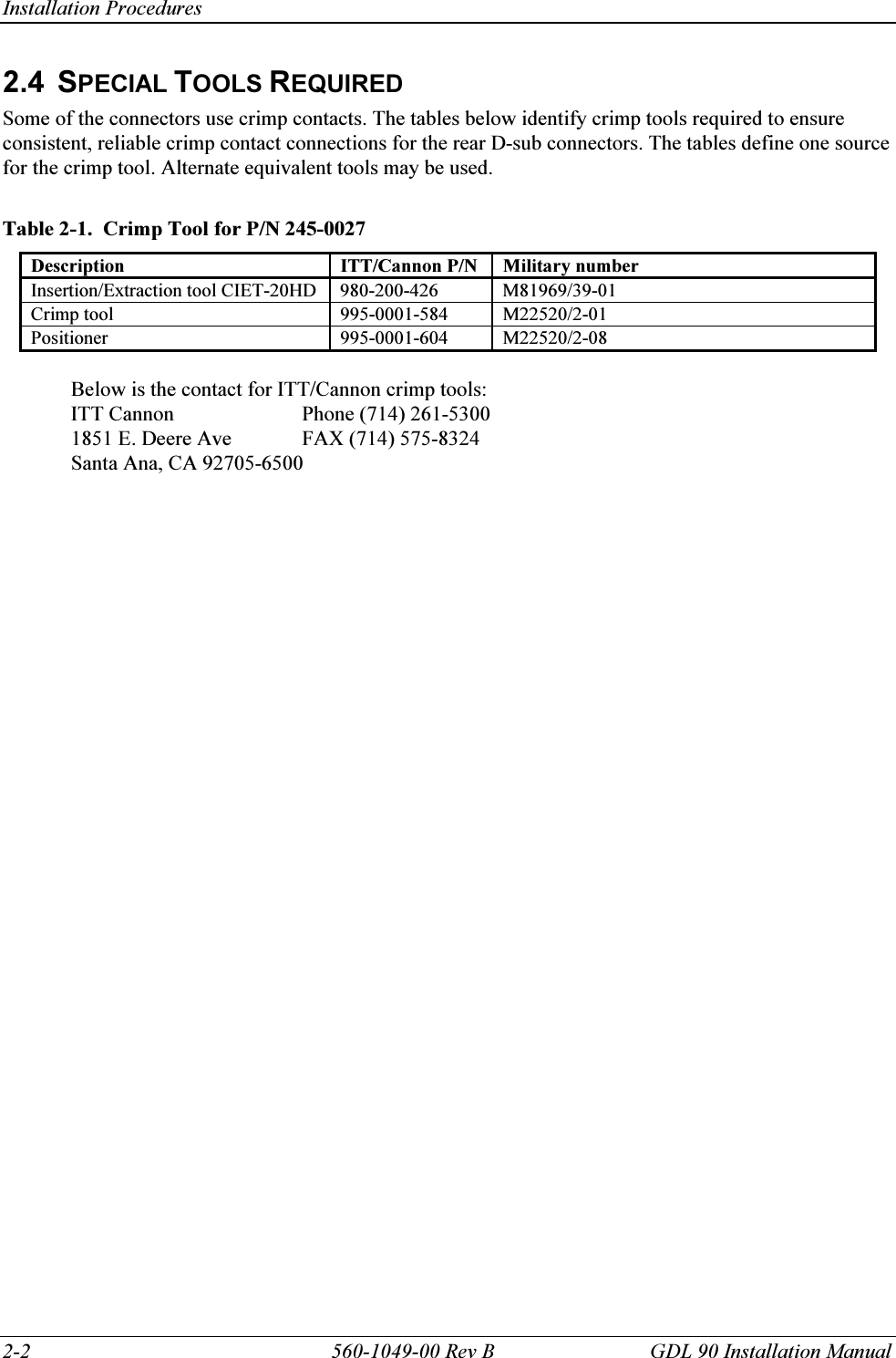
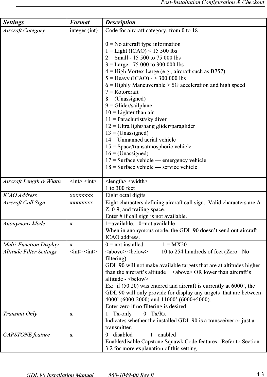
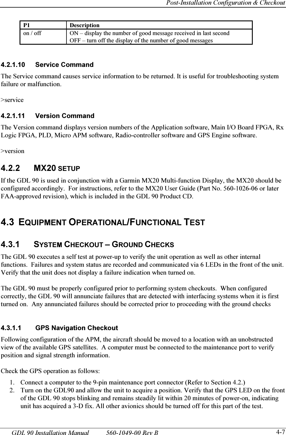
![Appendix A - Certification Data A-2 560-1049-00 Rev B GDL 90 Installation Manual A.2 MICRO APM ENVIRONMENTAL QUALIFICATION The Micro APM has been tested with the GDL 90 to the following environmental categories per procedures defined in RTCA/DO-160D. Tests were conducted in February to April 2004 using the original 1997 revision of DO-160D and the specification defined in PD3536. Environmental Qualification Form Nomenclature: Micro APM Part No.: 430-6200-xxx TSO No.: C154 Manufacturer: Garmin AT 2345 Turner Road SE Salem, Oregon 97302 Environment Section Category Comment Temperature and Altitude 4 F1 & A1 Operating temp ........ –20°C to +55°C Short time hi temp .... to +70°C Ground survival temp –55°C to +85°C Altitude .................... 55,000 feet Decompression 55,000 feet Overpressure Loss of cooling test -- not required Temperature Variation 5 B Minimum 5°C per minute Humidity 6 B Severe humidity environment. Operational Shocks and Crash Safety 7 B5R meets operational and crash safety shock tests 20 Gs at 11 ms. Vibration 8 S(M & B) Standard vibration. Meets without shock mounts. Explosion Proofness 9 X not applicable, no test required Waterproofness 10 X not applicable, no test required Fluids Susceptibility 11 X not applicable, no test required Sand and Dust 12 X not applicable, no test required Fungus Resistance 13 X not applicable, no test required Salt Spray 14 X not applicable, no test required Magnetic Effect 15 Z < 0.3 meter Power Input 16 A & B [1] for 28 and 14 volt systems Voltage Spike 17 A [1] Audio Frequency Conducted Susceptibility - Power Inputs 18 Z [1] Induced Signal Susceptibility 19 C Radio Frequency Susceptibility (Radiated and Conducted) 20 UV- Equipment tested to Category U (Conducted) Equipment tested to Category V (Radiated) No Pulse tests performed. Emission of Radio Frequency Energy 21 M [2] Lightning Induced Transient Susceptibility 22 XXXX [2] not applicable, no test required Lightning Direct Effects 23 X not applicable, no test required Icing 24 X not applicable, no test required Electrostatic Discharge (ESD) 25 A [1] APM powered by GDL 90. APM not directly exposed to this condition. [2] Maximum APM wire length 4 inches.](https://usermanual.wiki/Garmin-AT/GDL90A1H/User-Guide-445962-Page-60.png)