Garmin AT SL-70 Mode C Transponder User Manual Install manual
Garmin AT, Inc. Mode C Transponder Install manual
UserManual.wiki
>
Garmin AT
>
SL-70 User Manual
>
Install manual
Contents
1.
Operation manual
2.
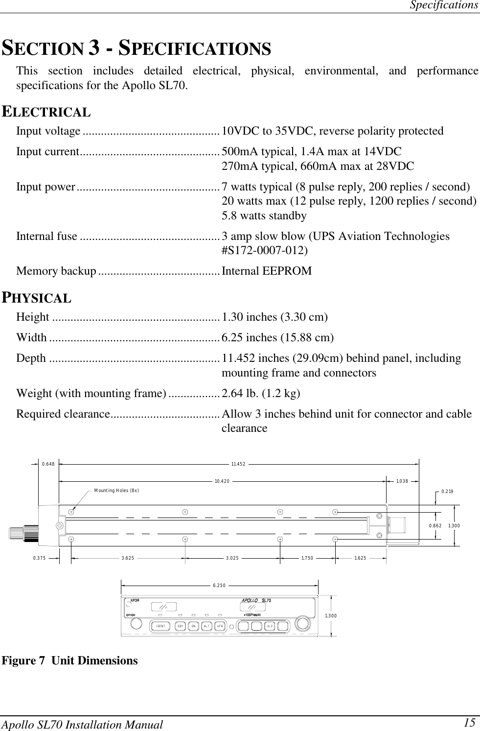
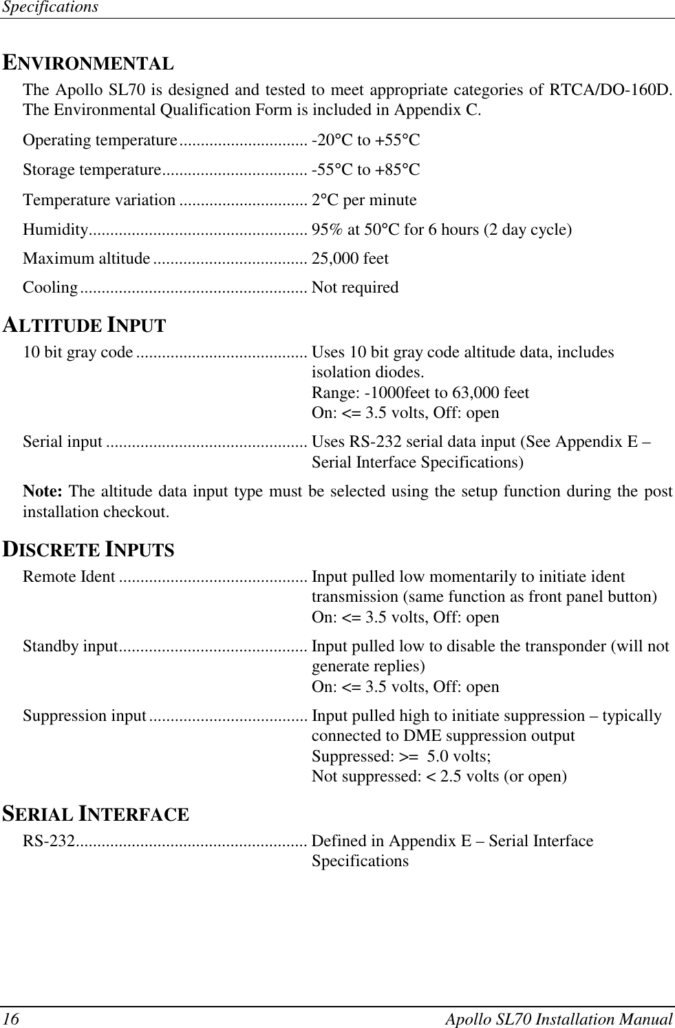
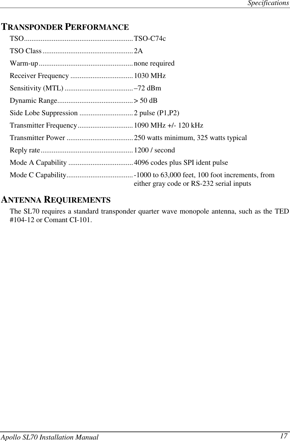
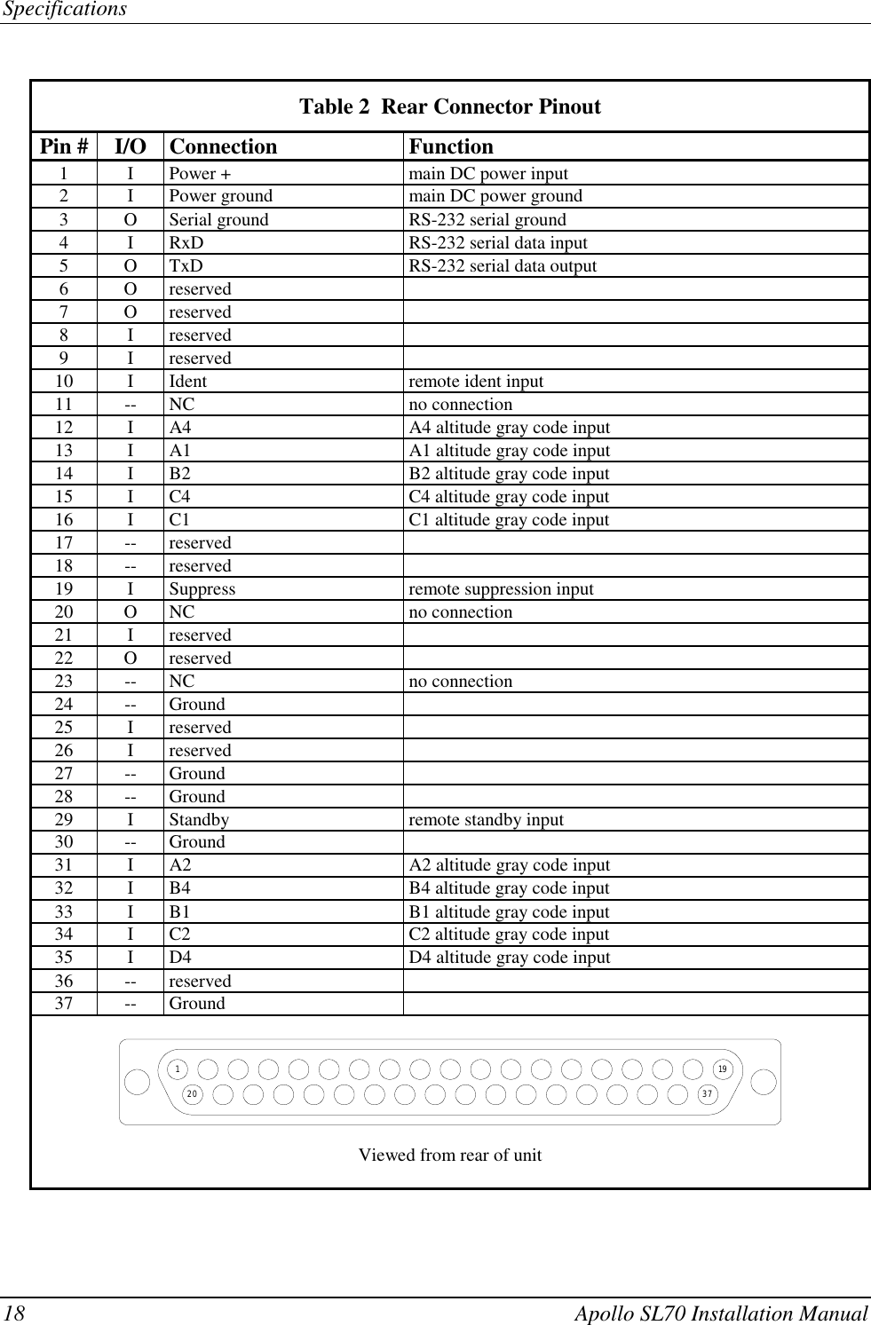
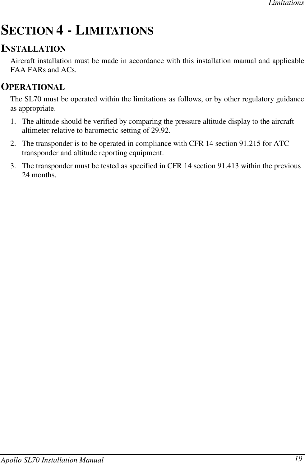
Install manual
Install manual
Navigation menu
Upload a User Manual
Namespaces
Wiki Guide
HTML
PDF
Info
Views
User Manual
Discussion / Help
Navigation

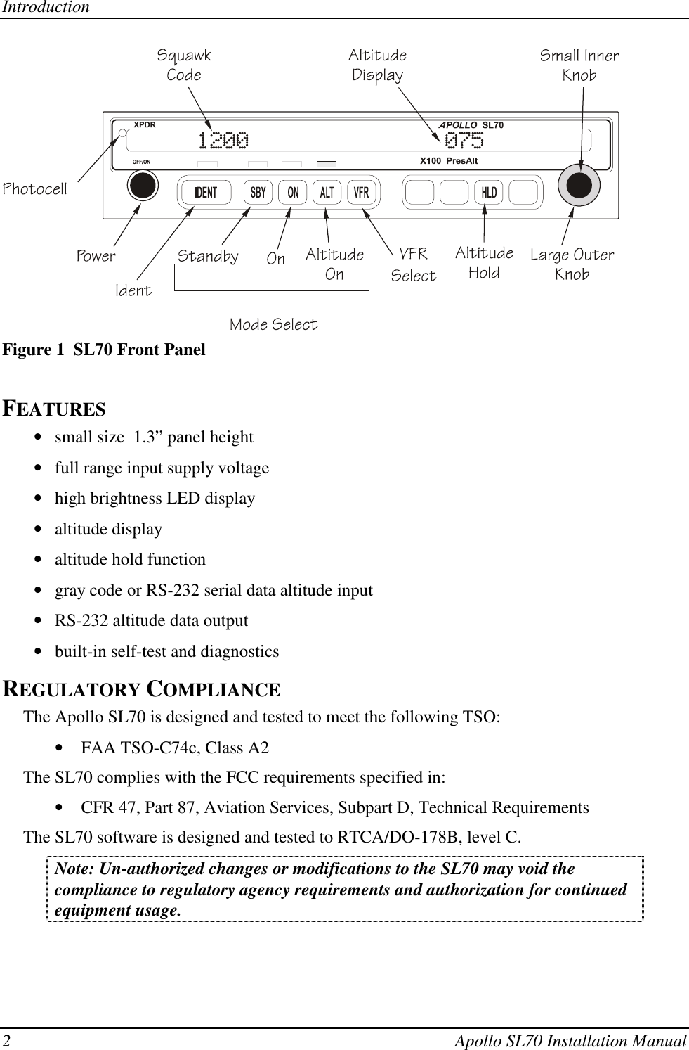
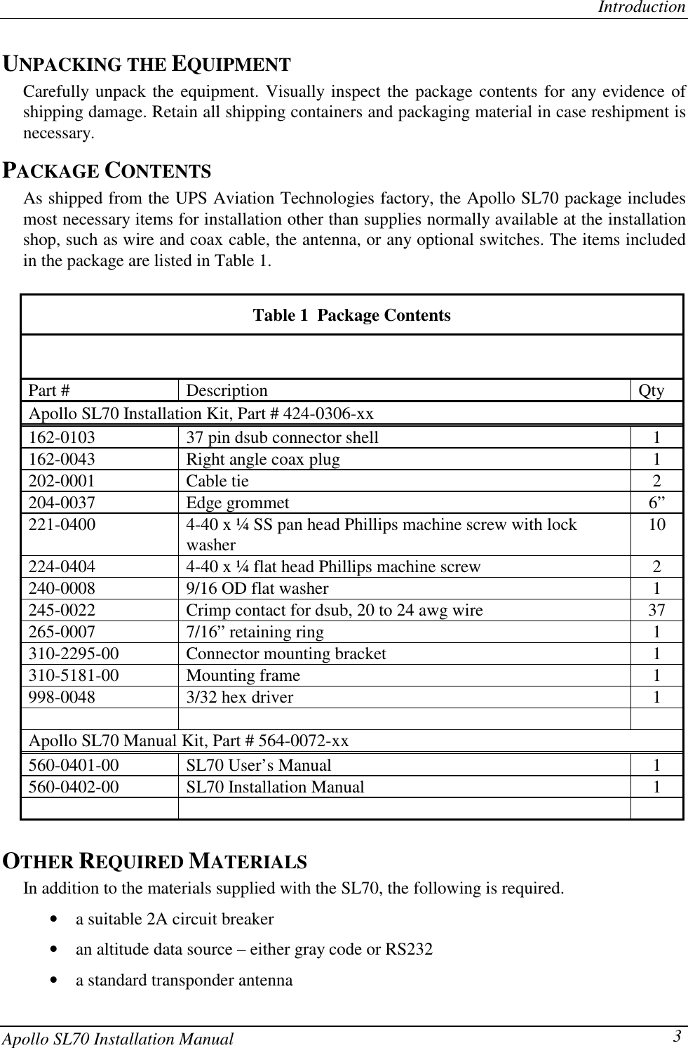
![Installation14 Apollo SL70 Installation ManualAPOLLO SL70 POST-INSTALLATION CHECKOUT LOG Date: ___/___/___By: _______________CONFIGURATION INFORMATION:Apollo SL70 430-6090-____ Mod ___Serial #_______________TEST MODE CHECKOUT AND SETUP:Self Test: [ ] Pass [ ] FailAltitude source: RS-232 baud rate: _________ [ ] Gray code (GRAY)VFR Code: ________ [ ] Serial RS-232 (SER)OPERATION / PERFORMANCE CHECK:Altitude data (on display): Performance verification: [ ] Pass [ ] PassExternal inputs: [ ] Remote ident checked [ ] N/A [ ] External standby [ ] N/ACOMMENTS:](https://usermanual.wiki/Garmin-AT/SL-70.Install-manual/User-Guide-55335-Page-20.png)