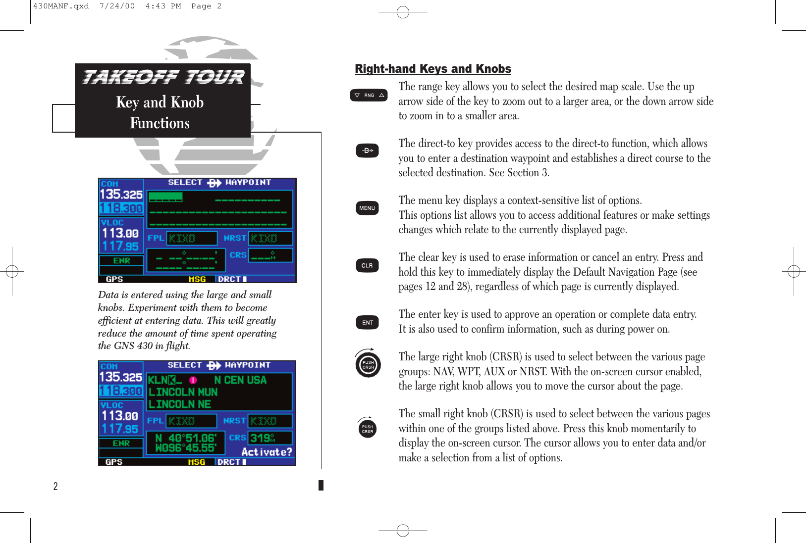
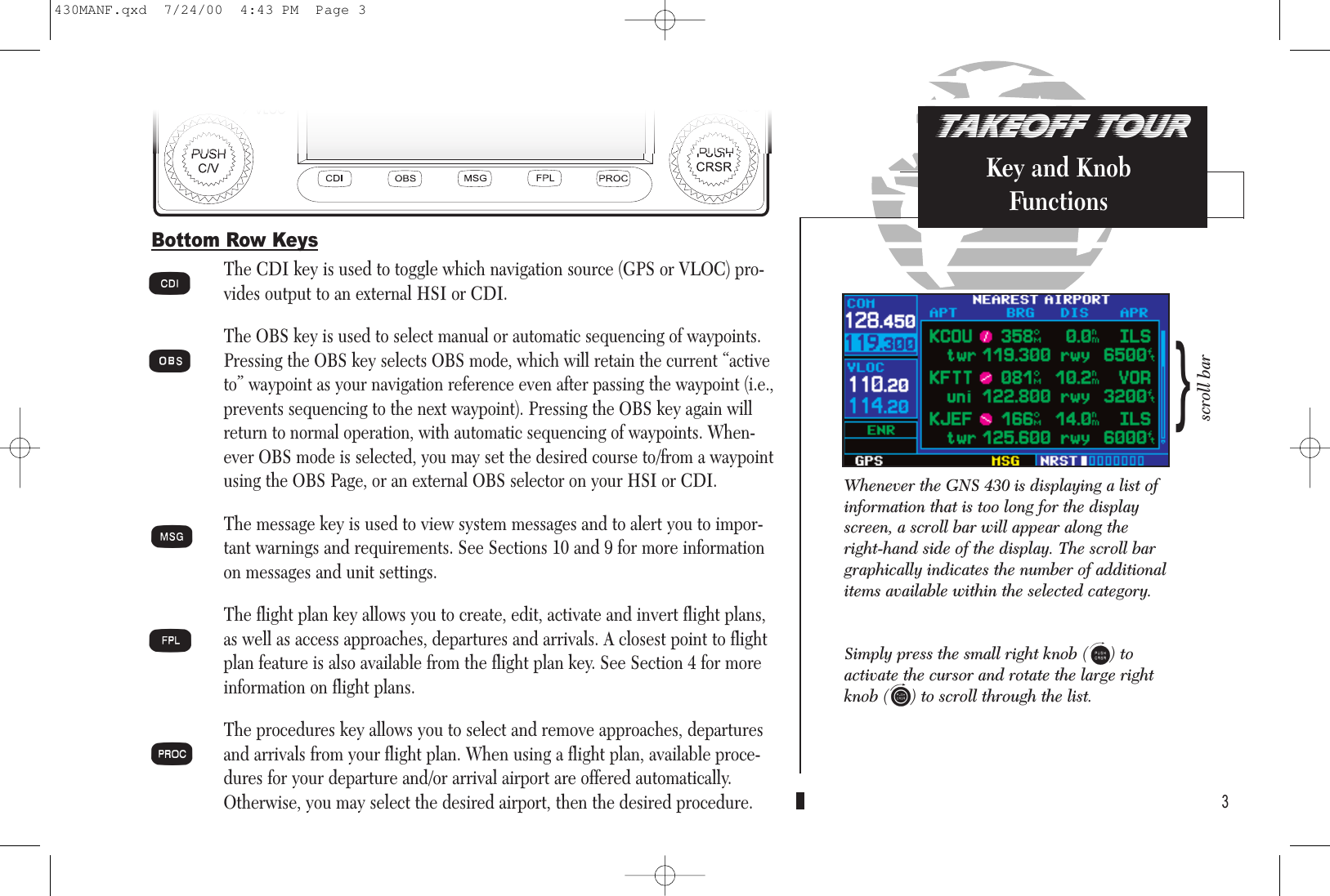
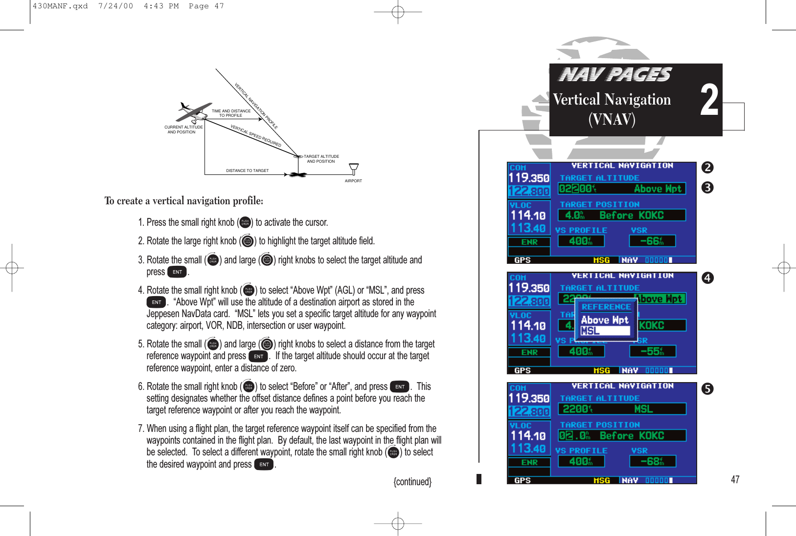
Garmin 0061100 Airborne Communications Transceiver operated under User Manual 430MANF
Garmin International Inc Airborne Communications Transceiver operated under 430MANF
UserManual.wiki
>
Garmin
>
0061100 User Manual
Users Manual
Navigation menu
Upload a User Manual
Namespaces
Wiki Guide
HTML
PDF
Info
Views
User Manual
Discussion / Help
Navigation

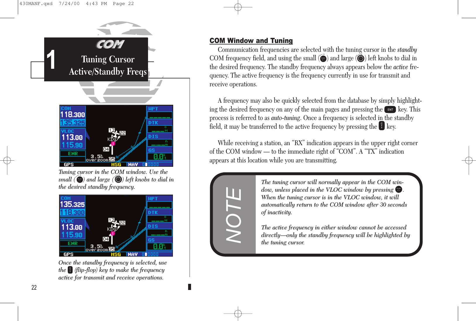

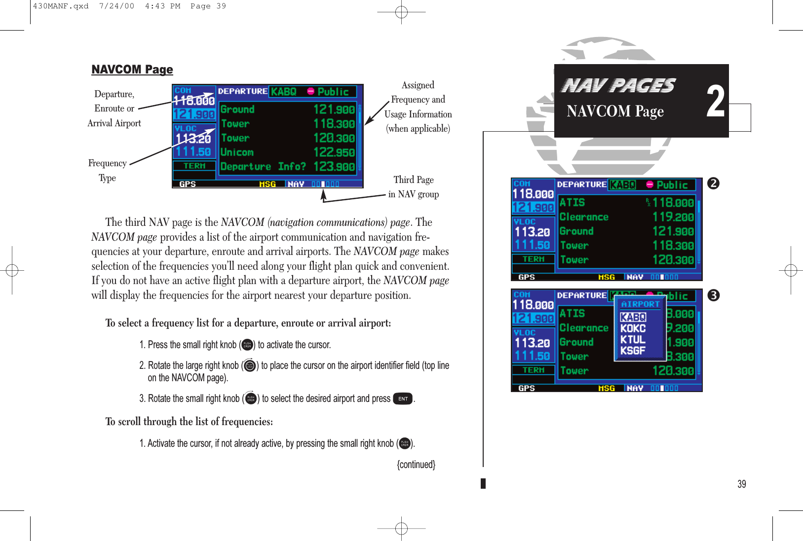
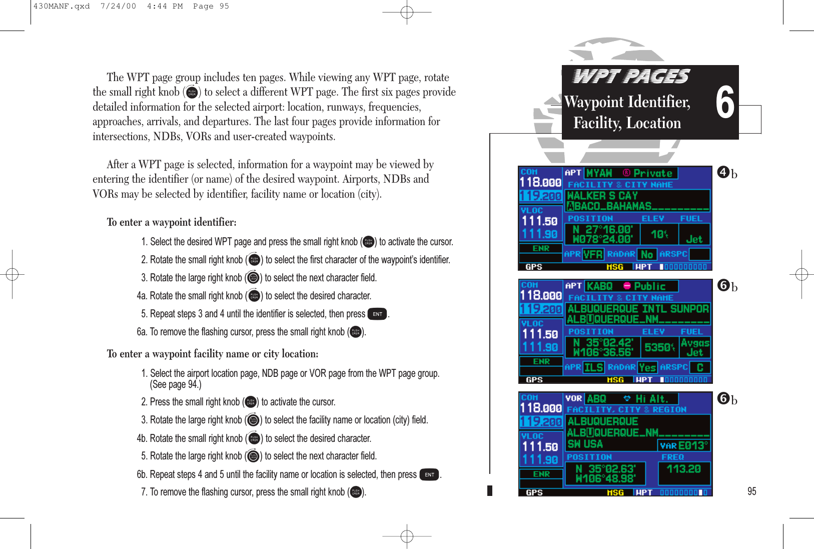
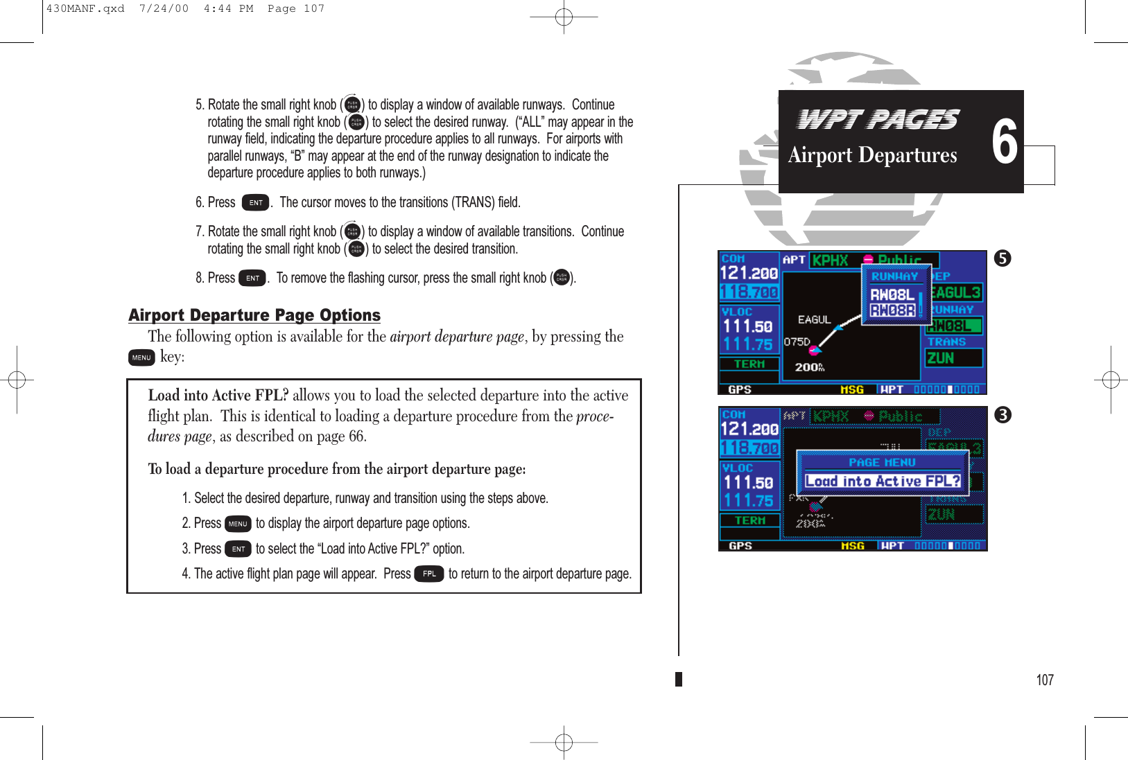
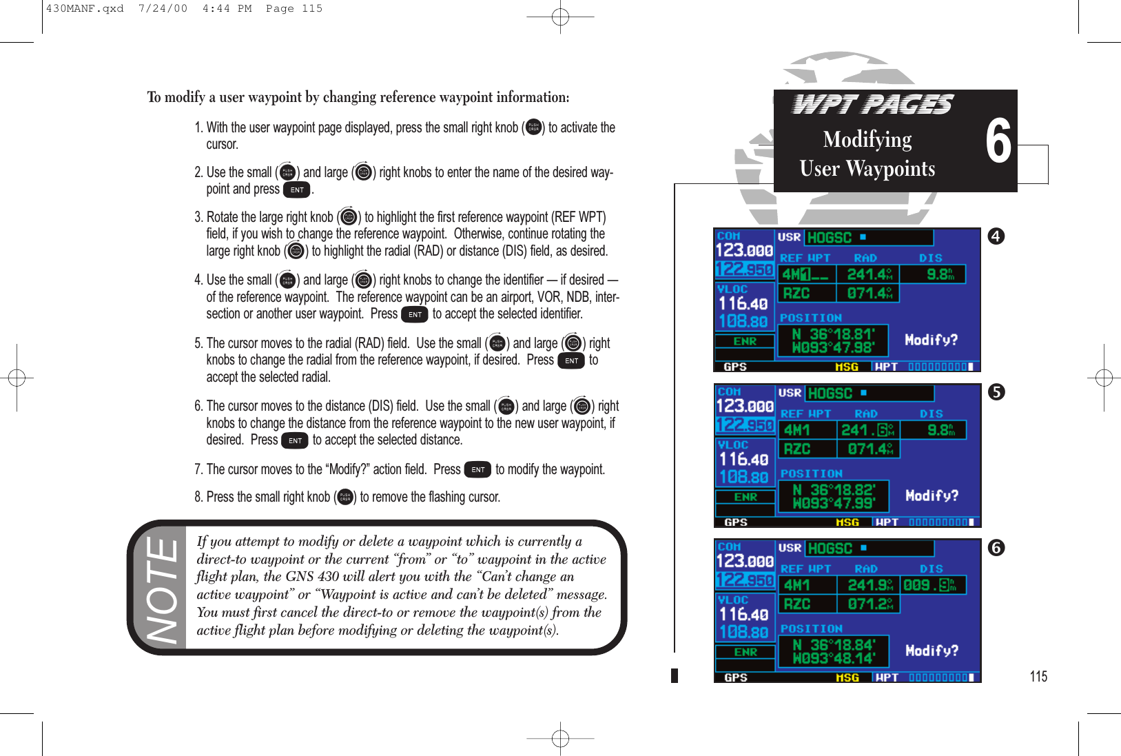

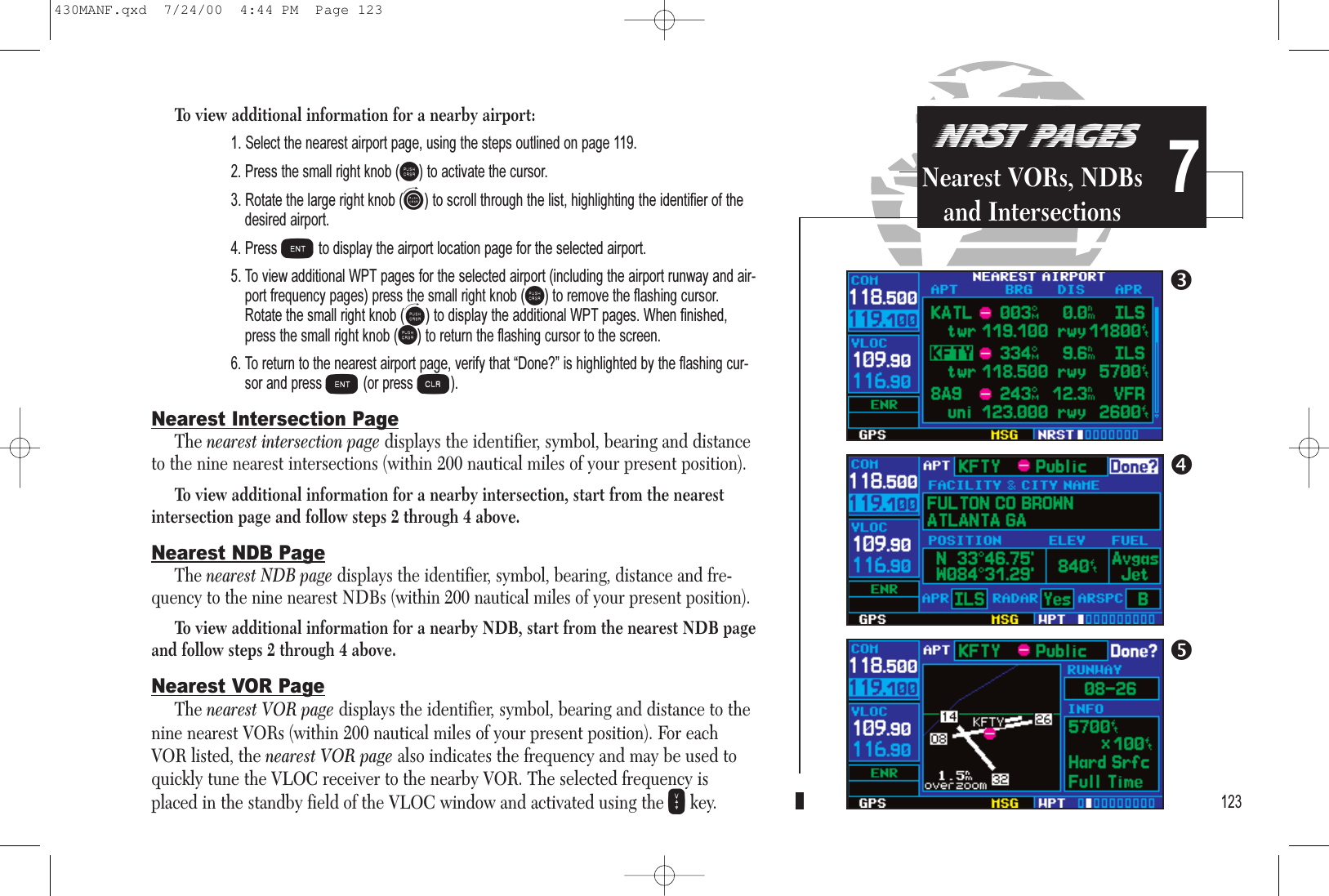
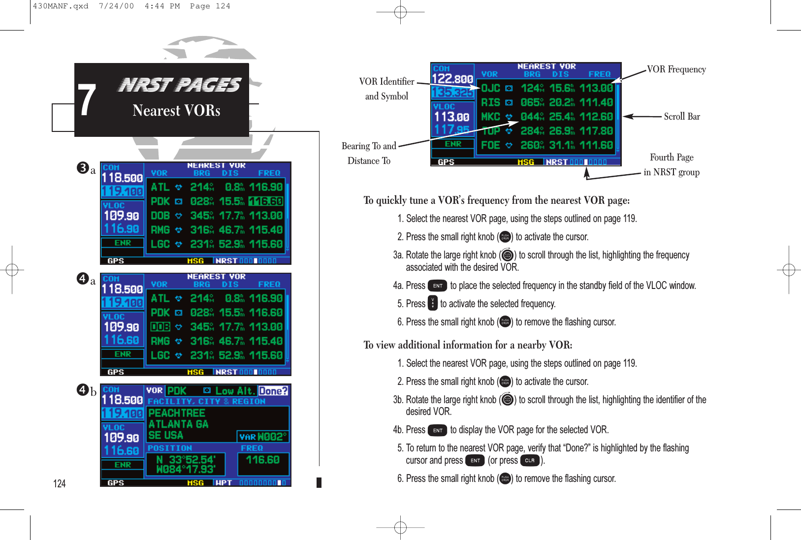
![Nearest Flight Service Station (FSS) PageThe nearest flight service station page displays the facility name, bearing to anddistance to the five nearest FSS points of communication (within 200 nautical milesof your present position). For each FSS listed, the nearest flight service station pagealso indicates the frequency(s) and may be used to quickly tune the COM trans-ceiver to the FSS’s frequency. The selected frequency is placed in the standby fieldof the COM window and activated using the Wkey.For duplex operations, “RX” and “TX” indications will appear beside the listedfrequencies—indicating “receive only” or “transmit only” frequencies. The associ-ated VOR is also provided for reference. To quickly tune an FSS’s frequency from the nearest flight service station page:1. Select the nearest flight service station page, using the steps outlined on page 119.2. Press the small right knob (r) to activate the cursor.3. Rotate the small right knob (a) to scroll through the list, selecting the desired FSS.4. Rotate the large right knob (d) to scroll down the page, highlighting the desired frequency (COM frequency[s] or VOR frequency for duplex operation).{continued}126NRST PAGESNearest FSS7FSS NameSeventh Pagein NRST groupFrequency(s)Bearing To andDistance ToVOR Identifier(for duplex operation)430MANF.qxd 7/24/00 4:44 PM Page 126](https://usermanual.wiki/Garmin/0061100/User-Guide-183064-Page-134.png)
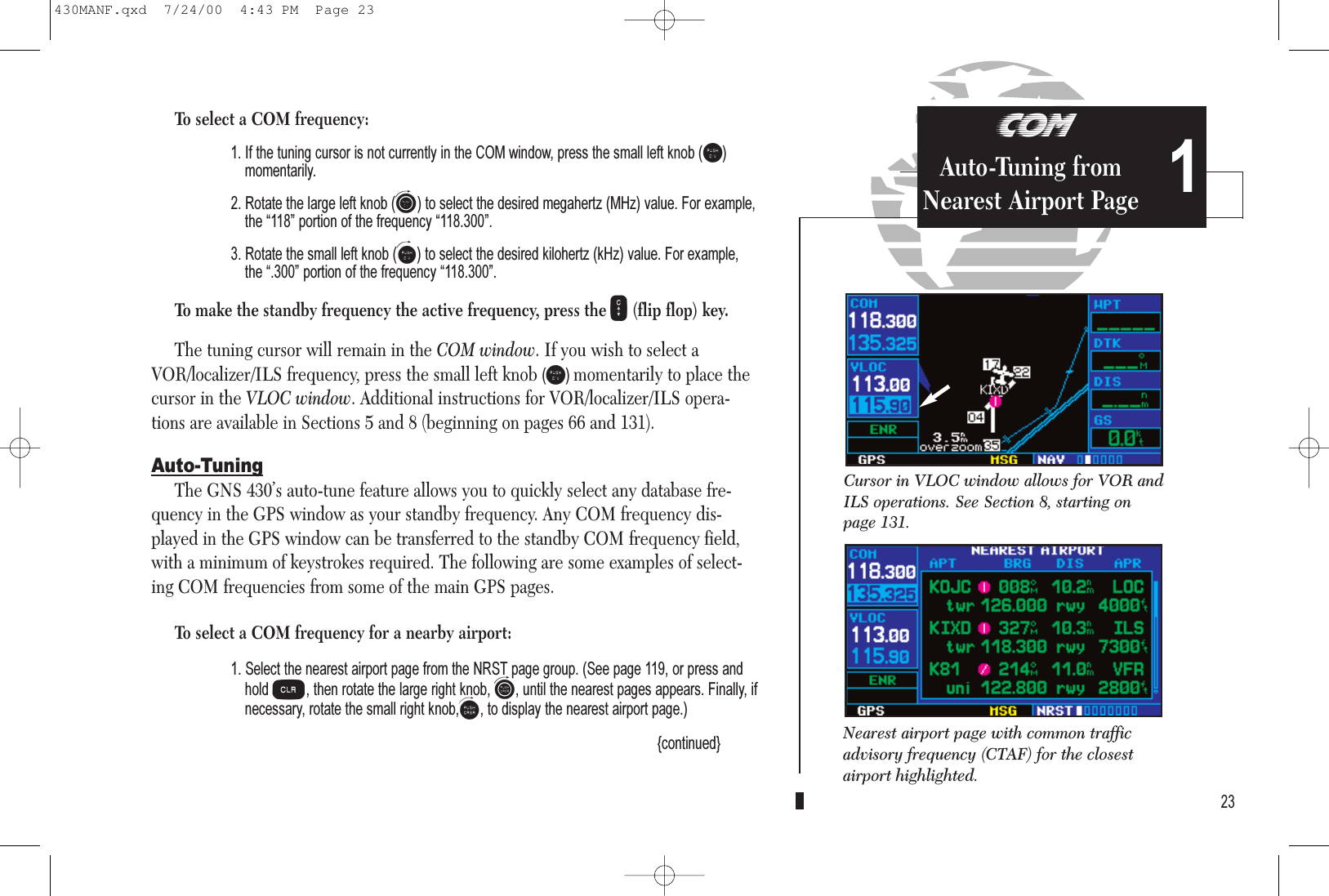
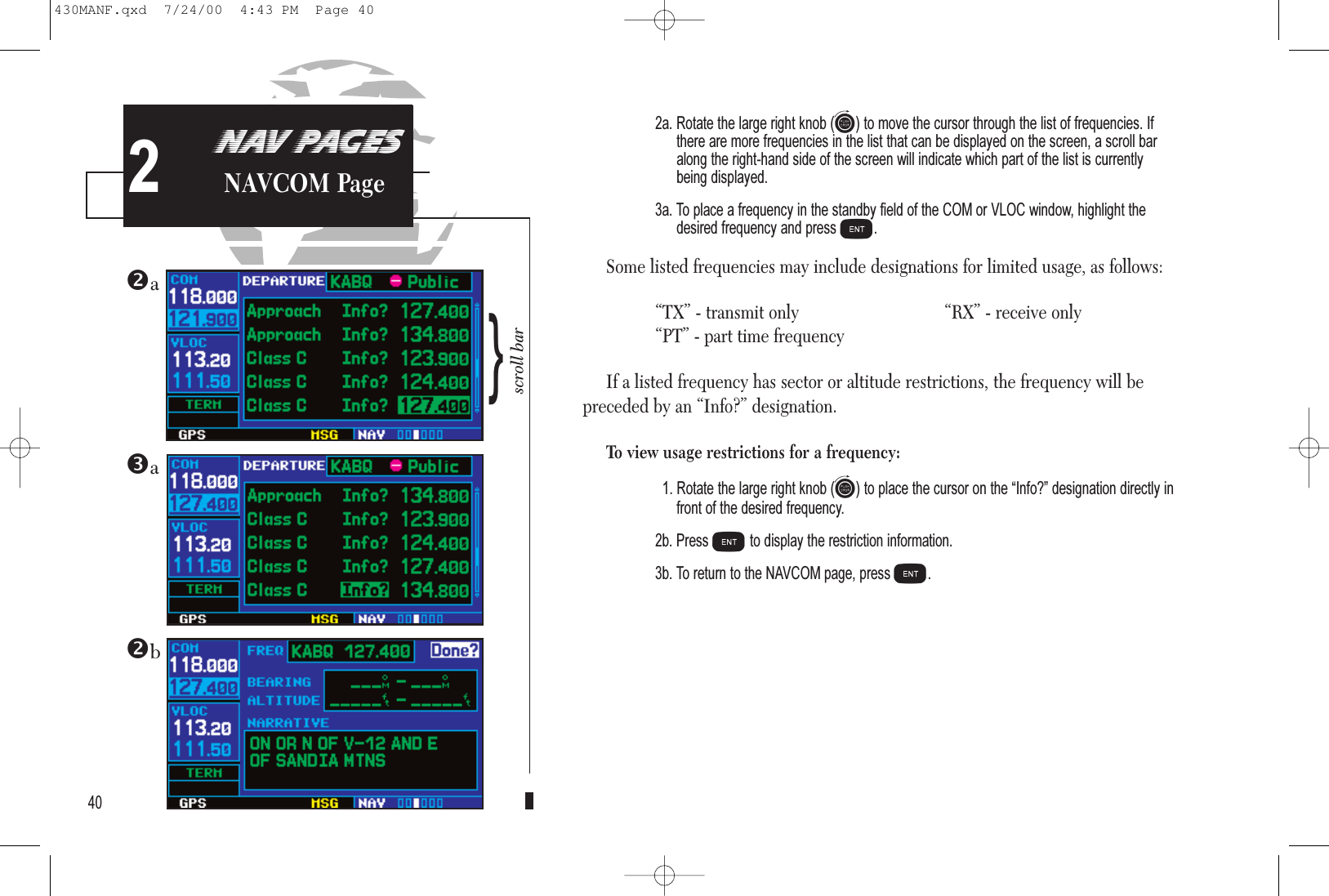
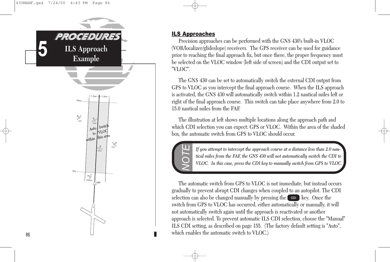
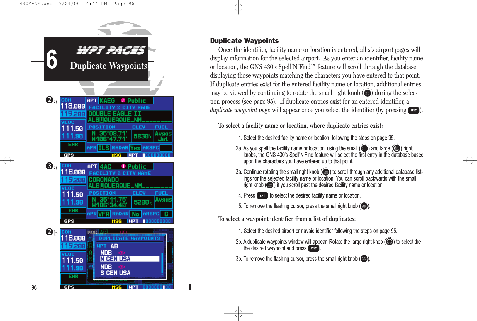
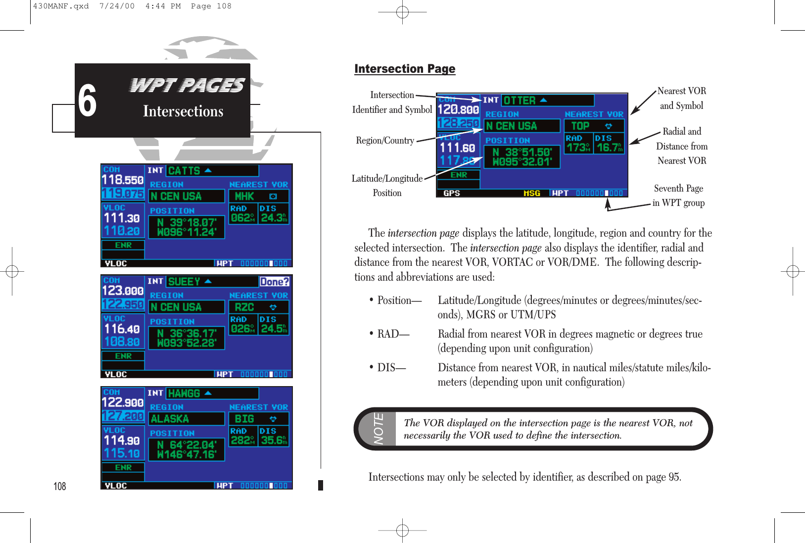
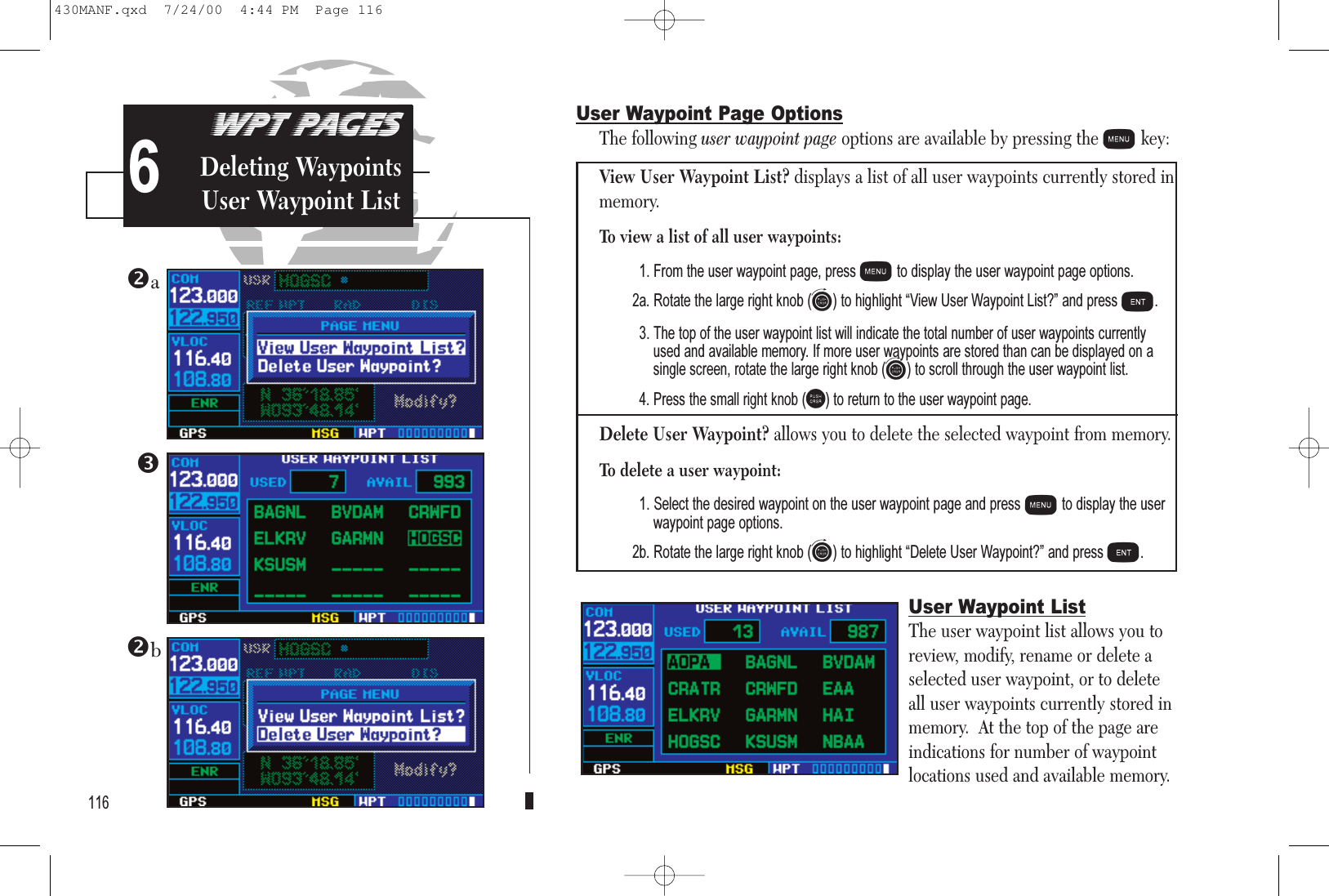
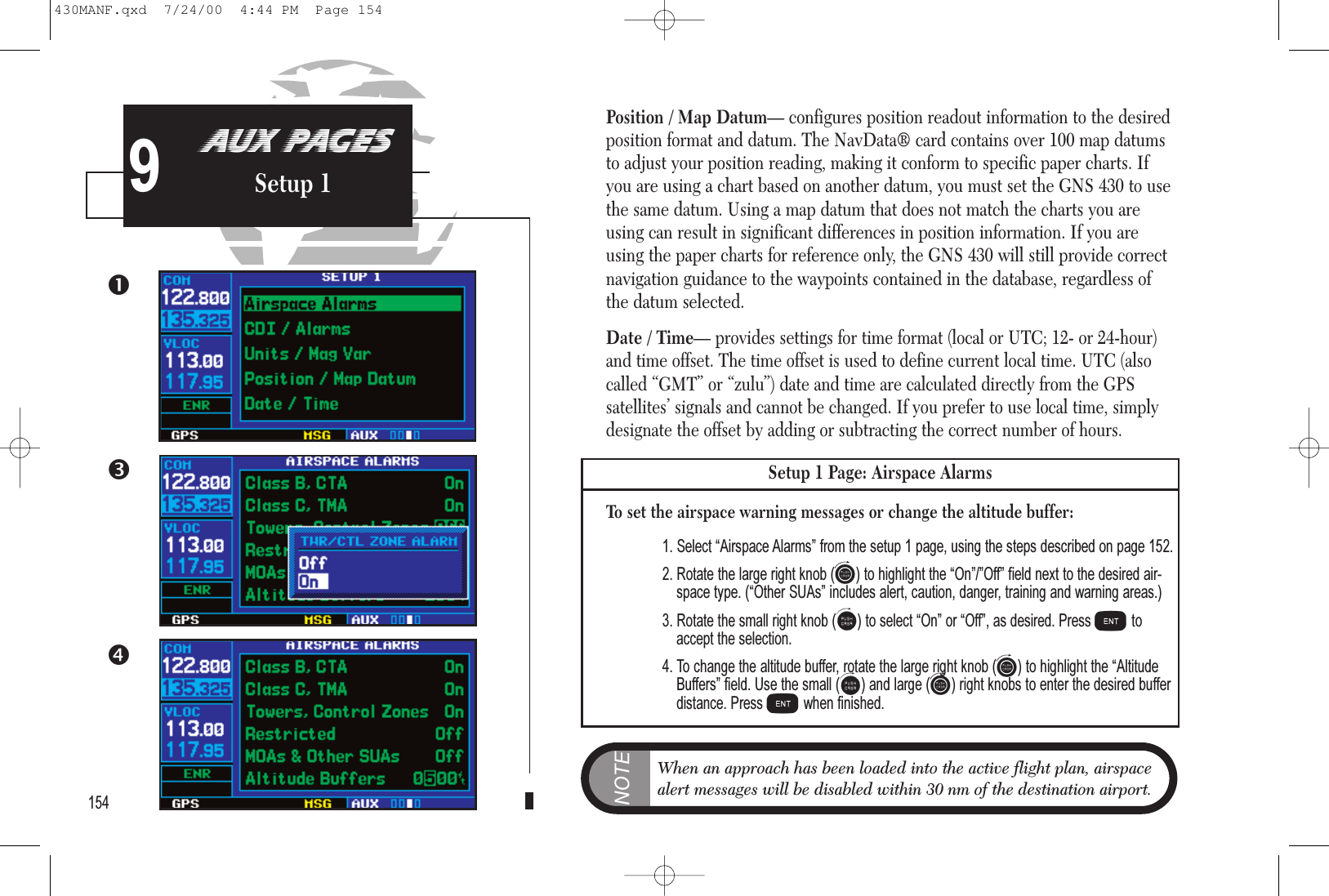
![153AUX PAGESSetup 1 9CDI / Alarms— allows you to define the scale for the GNS 430’s on-screen course devia-tion indicator. The scale values represent full scale deflection for the CDI to either side.The default setting is “5.0 nm”. At this setting, the CDI scale is set to 5 nm during theenroute phase of flight. Within 30 nm of your destination airport the CDI scale graduallyramps down to 1.0 nm (terminal area). Likewise when leaving your departure airport theCDI scale is set to 1.0 nm and gradually ramps UP to 5 nm beyond 30 nm (from thedeparture airport).During approach operations the CDI scale gradually ramps down even further, to 0.3 nm.This transition normally occurs within 2.0 nm of the final approach fix (FAF). If a lowerCDI scale setting is selected (i.e., 1.0 nm or 0.3 nm) the higher scale settings will not beselected during ANY phase of flight. For example, if 1.0 nm is selected, the GNS 430 willuse this for the enroute and terminal phase and ramp down to 0.3 nm during anapproach. Note that the Receiver Autonomous Integrity Monitoring (RAIM) protectionlimits listed below follow the selected CDI scale and corresponding modes:CDI Scale RAIM Protection+/-5.0 nm or Auto (en route) 2.0 nm+/-1.0 nm or Auto (terminal) 1.0 nm+/-0.3 nm or Auto (approach) 0.3 nmAn “auto” ILS CDI selection allows the GNS 430 to automatically switch the externalCDI from the GPS receiver to the VLOC receiver, when established on the finalapproach course. (See page 86.) Or, select “manual” to manually switch the external CDIconnection, as needed.An arrival alarm, provided on the CDI / alarms page, may be set to notify you with a mes-sage when you have reached a user-defined distance to the final destination (the direct-towaypoint or the last waypoint in a flight plan). Once you have reached the set distance(up to 99.9 units), an “Arrival at [waypoint]” message will be displayed.Units / Mag Var— allows you to configure the displayed data to standard or metric unitsof measure. This setting applies to distance, speed, altitude, fuel, pressure and tempera-ture. Also provides three magnetic variation (heading) options: True, Auto or User-defined. If “Auto” is selected, all track, course and heading information will be correctedto the magnetic variation computed by the GPS receiver. The “True” setting will refer-ence all information to true north, and the “User” setting will correct information to anuser-entered value.CDI scales and corresponding modes:EnrouteTerminalApproach430MANF.qxd 7/24/00 4:44 PM Page 153](https://usermanual.wiki/Garmin/0061100/User-Guide-183064-Page-161.png)
![Arrival at waypoint [waypoint name]—You are within the arrivalalarm circle for the indicated waypoint. The size of the arrival alarmcircle is defined from the “CDI / alarms” menu option on the setup 1page.Cannot navigate locked FPL—You have attempted to navigate aflight plan (FPL) with one or more locked waypoints. A waypoint canbe “locked” when the NavData® card is replaced and thewaypoint(s) does not exist in the new database.Can’t change an active waypoint—An attempt has been made tomodify the position of the active “to” or “from” waypoint. The GNS430 will not allow modifications to user waypoints currently being utilized for navigation guidance.Can’t delete an active or FPL waypoint—An attempt has beenmade to delete the active “to” or “from” waypoint. The GNS 430 willnot allow you to delete user waypoints currently being utilized for navigation guidance.CDI key stuck—TheCkey is stuck in the enabled (or pressed”)state. Try pressing theCkey again to cycle its operation. If themessage persists, contact your GARMIN dealer for assistance.Check unit cooling—The GNS 430 has detected excessive displaybacklighting temperature. The backlighting has been automaticallydimmed to reduce the temperature. Check for adequate ventilation orcheck cooling air flow. Contact your GARMIN dealer for assistance.COM has failed—The GNS 430 has detected a failure in its com-munications transceiver. The COM transceiver is not available andthe unit should be returned to your GARMIN dealer for service.COM is not responding—Internal system-to-system communica-tion between the main processor and the COM transceiver hasfailed. Operational status of the COM transceiver is unknown andthe unit should be returned to your GARMIN dealer for service.COM needs service—The GNS 430 has detected a failure in itscommunications transceiver. The COM transceiver may still beusable, but the unit should be returned (at your earliest convenience)to your GARMIN dealer for service.COM push-to-talk key stuck—The external push-to-talk (PTT)switch is stuck in the enabled (or “pressed”) state. Try pressing thePTT switch again to cycle its operation. If the message persists, con-tact your GARMIN dealer for assistance.COM remote transfer key is stuck—The remote COM transferswitch is stuck in the enabled (or “pressed”) state. Try pressing theswitch again to cycle its operation. If the message persists, contactyour GARMIN dealer for assistance.COM transfer key stuck—The Wkey is stuck in the enabled (or“pressed”) state. Try pressing the Wkey again to cycle its operation.If the message persists, contact your GARMIN dealer for assistance.164MESSAGES,aBBREVIATIONS& nav tERMS10430MANF.qxd 7/24/00 4:44 PM Page 164](https://usermanual.wiki/Garmin/0061100/User-Guide-183064-Page-172.png)
![RAIM position warning—Although sufficient GPS satellite cover-age may exist, Receiver Autonomous Integrity Monitoring (RAIM)has determined the information from one or more GPS satellites maybe in error. The resulting GPS position may be in error beyond the limits allowed for your current phase of flight. Cross-check your posi-tion with an alternate navigation source. If the warning occurs duringa final approach segment (FAF to MAP), execute the publishedmissed approach.Scheduler message -- [user entered text]—The user-enteredscheduler message time has expired, and the scheduler message isdisplayed.Searching the sky—The GNS 430 is searching the sky for GPS satellite almanac data or the GPS receiver is in AutoLocate Mode.Allow the unit to complete data collection (approximately 5 minutes)before turning it off.Select appropriate frequency for approach—You are inboundand within 3 nautical miles of the FAF; and the active VLOC fre-quency does not match the published frequency for the approach.Tune the standby VLOC frequency to the proper frequency andpress the Vkey to “activate” the frequency.Select auto sequence mode—The Okey was pressed, dis-abling auto sequencing of waypoints (in a flight plan or instrument procedure). The Okey should be pressed again to enable autosequencing, because 1) no destination waypoint has been selected, or2) the GPS receiver cannot currently determine its position.Select VLOC on CDI for approach—You are inbound and within 3 nautical miles of the FAF; and the active approach is not aGPS-approved approach. Verify that the VLOC receiver is tuned tothe proper frequency and press the Ckey to display “VLOC”(directly above the Ckey).Set course to [###]°—The course select for the external CDI (orHSI) should be set to the specified course. The message will onlyoccur when the current selected course is greater than 10° differentfrom the desired track.Steep turn ahead—This message appears approximately oneminute prior to a turn in one of the following three conditions: 1) theturn requires a bank angle in excess of 25° in order to stay on course,2) the turn requires a course change greater than 175°, or 3) during a DME arc approach the turn anticipation distance exceeds90 seconds.Stored data was lost—All user waypoints, flight plans and system settings have been lost due to a memory battery failure or systemreset. 169MESSAGES,aBBREVIATIONS& nav tERMS10430MANF.qxd 7/24/00 4:44 PM Page 169](https://usermanual.wiki/Garmin/0061100/User-Guide-183064-Page-177.png)