Garmin 00855 GPS 10; GPS10 DELUXE User Manual INTRODUCTION
Garmin International Inc GPS 10; GPS10 DELUXE INTRODUCTION
UserManual.wiki
>
Garmin
>
00855 User Manual
USERS MANUAL
Navigation menu
Upload a User Manual
Namespaces
Wiki Guide
HTML
PDF
Info
Views
User Manual
Discussion / Help
Navigation
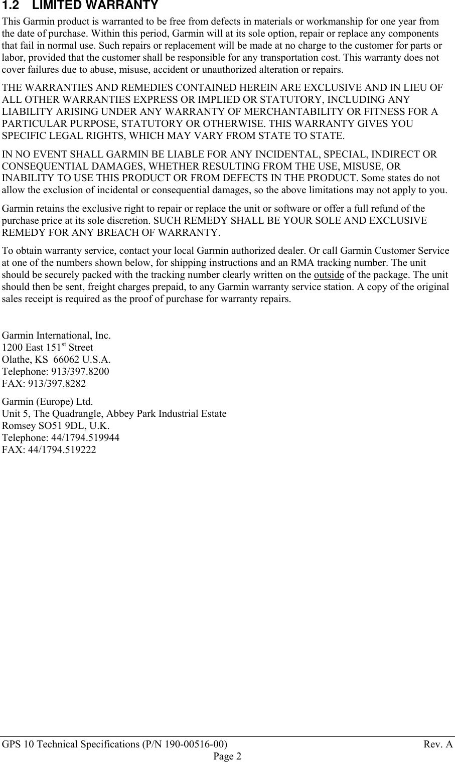
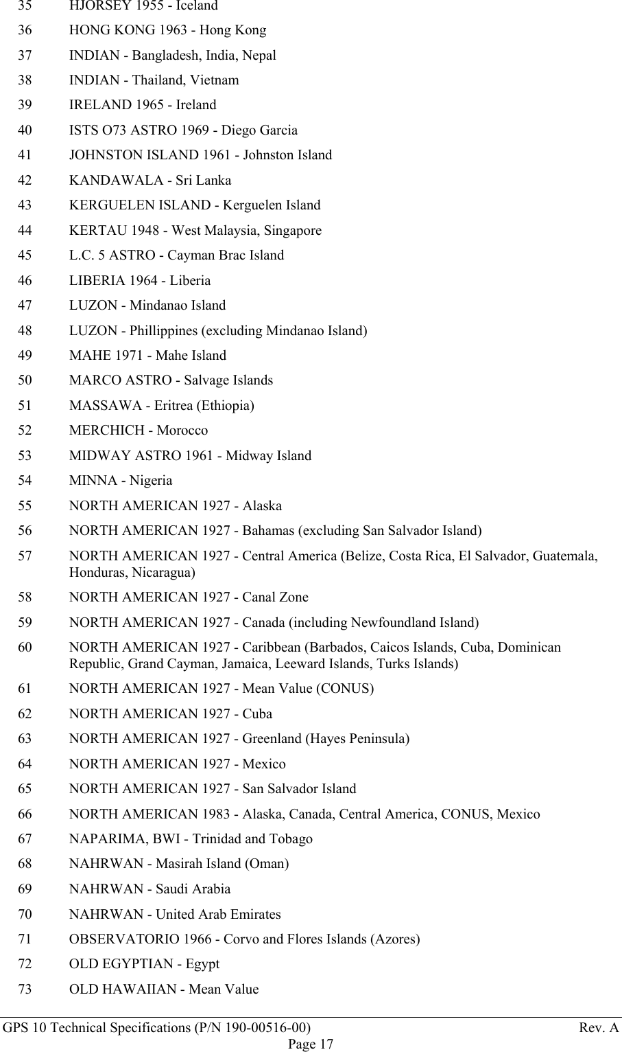
![GPS 10 Technical Specifications (P/N 190-00516-00) Rev. APage 21Position RecordThe Position Record has a record identifier of typedef struct{float alt;float epe;float eph;float epv;int fix;double gps_tow;double lat;double lon;float lon_vel;float lat_vel;float alt_vel;float msl_hght;int leap_sec;long grmn_days;} cpo_pvt_data;alt Ellipsoid altitude (meters)epe Est pos error (meters)eph Pos err, horizontal (meters)epv Pos err, vertical (meters)fix 0 = no fix; 1 = no fix; 2 = 2D; 3 = 3D; 4 = 2D differential; 5 = 3D differential;6 and greater - not definedgps_tow GPS time of week (sec)lat Latitude (radians)lon Longitude (radians)lon_vel Longitude velocity (meters/second)lat_vel Latitude velocity (meters/second)alt_vel Altitude velocity (meters/second)msl_hght Mean sea level height (meters)leap_sec UTC leap secondsgrmn_days Garmin days (days since December 31, 1989)Receiver Measurement Recordtypedef struct { unsigned long cycles; double pr; unsigned int phase; char slp_dtct; unsigned char snr_dbhz; char svid; char valid;} cpo_rcv_sv_data;typedef struct { double rcvr_tow; int rcvr_wn; cpo_rcv_sv_data sv[ 12 ];} cpo_rcv_data;rcvr_tow Receiver time of week (seconds)rcvr_wn Receiver week numbercycles Number of accumulated cyclespr Pseudorange (meters)phase To convert to (0 -359.999) multiply by 360.0 and divide by 2048.0slp_dtct 0 = no cycle slip detected; non-zero = cycle slip detected](https://usermanual.wiki/Garmin/00855/User-Guide-501436-Page-27.png)
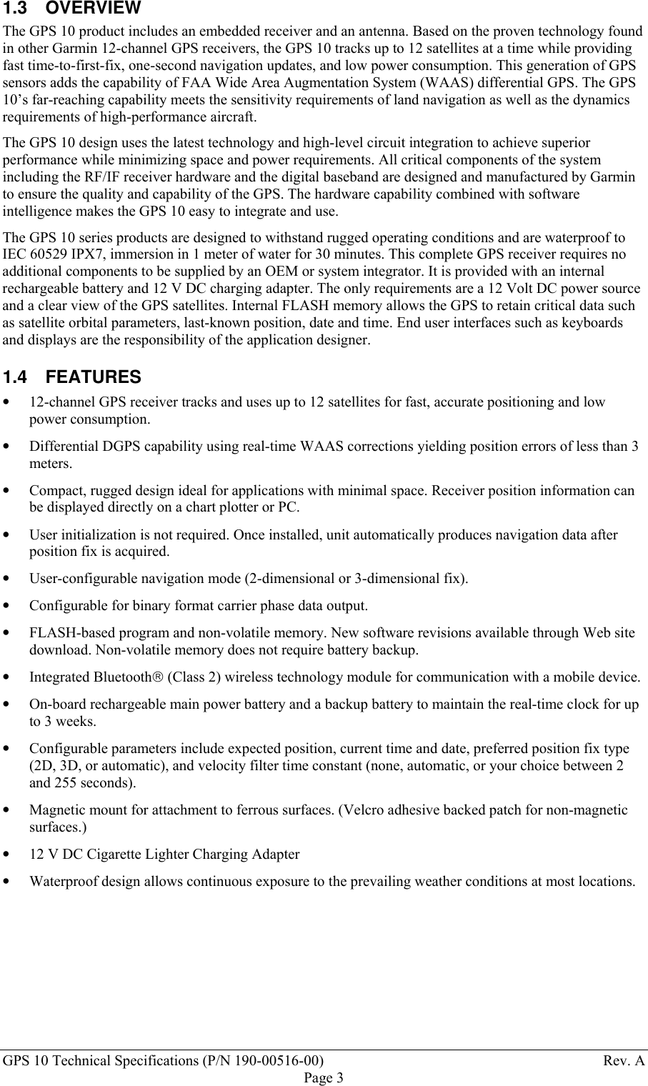
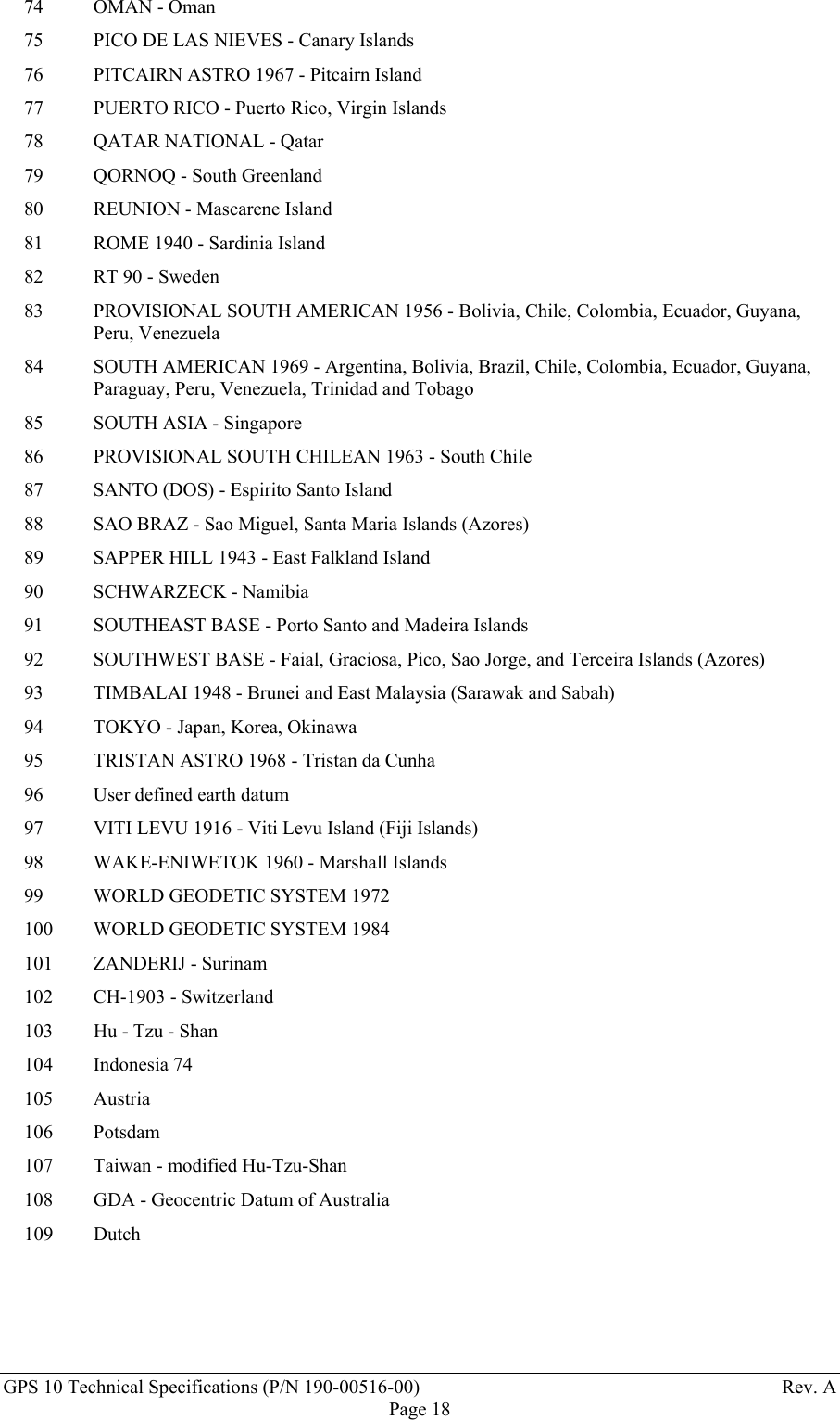
![GPS 10 Technical Specifications (P/N 190-00516-00) Rev. APage 22snr_dbhz Signal strength - db Hzsvid Satellite number (0-31 and 119-138 for WAAS) Note - add 1 to offset to current svidnumbers. valid 0 = information not valid; non-zero = information validDLE and ETX bytes:Sample C code to receive the two records should filter DLE and ETX bytes as described below:typedef enum { DAT, DLE, ETX } rx_state_type;/* Declare and initialize static variables */static char in_que[ 256 ];static int in_que_ptr = 0;static rx_state_type rx_state = DAT;...void add_to_que( char data ){#define DLE_BYTE 0x10#define ETX_BYTE 0x03if ( rx_state == DAT ) { if ( data == DLE_BYTE ) { rx_state = DLE; } else { in_que[ in_que_ptr++ ] = data; } }else if ( rx_state == DLE ) { if ( data == ETX_BYTE ) { rx_state = ETX; } else { rx_state = DAT; in_que[ in_que_ptr++ ] = data; } }else if ( rx_state == ETX ) { if ( data == DLE_BYTE ) { rx_state = DLE; } }if ( in_que_ptr > 255 ) { in_que_ptr = 0; }](https://usermanual.wiki/Garmin/00855/User-Guide-501436-Page-28.png)