Garmin 0104450 LICENSED NON-BROADCAST TRANSMITTER (TAS) AND TRAFFIC ALERT & COLLISION AVOIDANCE SYSTEM (TCAS) PROCESSOR User Manual 1
Garmin International Inc LICENSED NON-BROADCAST TRANSMITTER (TAS) AND TRAFFIC ALERT & COLLISION AVOIDANCE SYSTEM (TCAS) PROCESSOR Users Manual 1
Garmin >
Contents
- 1. Users Manual 1
- 2. Users Manual 2
Users Manual 1
GNS 430(A) Pilot’s Guide and Reference
190-00140-00 Rev. P 12-11
SECTION 12
ADDITIONAL FEATURES
12.2 TRAFFIC ADVISORY SYSTEMS (TAS)
Introduction
All information in this section pertains to the display
and control of the Garmin GNS 430/GTS 800 interface.
NOTE: This section assumes the user has
experience operating the GNS 430 and the
GTS 800.
NOTE: References to the GTS 800 throughout
this document refer equally to the GTS 820 and
GTS 850 unless otherwise noted.
System Description
The GNS 430 provides an optional display interface for
the GTS 800 Trafc Advisory System (TAS). The GTS 800
monitors the airspace surrounding an aircraft, and advises
the ight crew where to look for transponder-equipped
aircraft that may pose a collision threat.
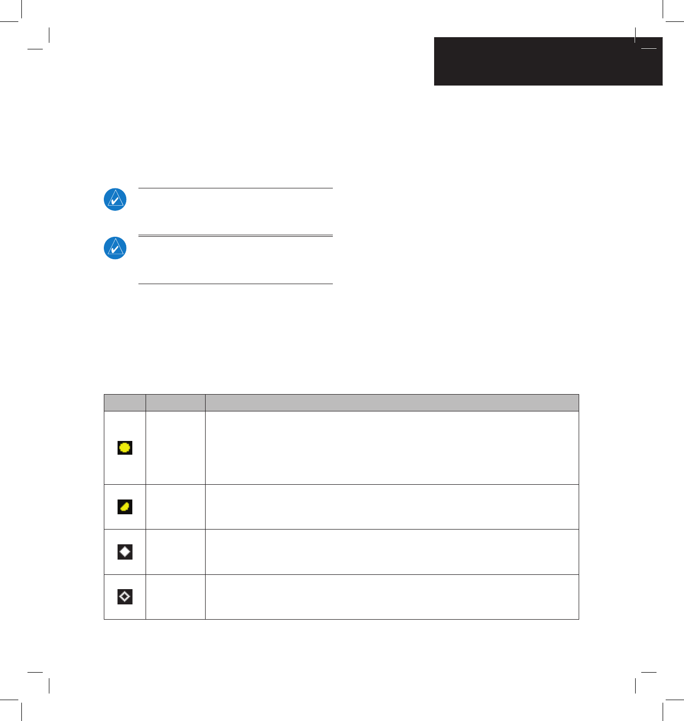
Symbol Traffic Type Description
Traffic
Advisory (TA)
A TA (Traffic Advisory) is generated when the GTS 800 predicts that an intruder aircraft may
pose a collision threat. A solid yellow circle represents an intruder aircraft that is on a course
that projects to intercept (defined by a 0.5 nm horizontal radius and a relative altitude of
± 500 ft) the pilot’s current course within 34 seconds. A TA consists of the traffic symbol and
an aural alert (e.g., “traffic, 12 o’clock, high, 3 miles”).
Out-of-
Range Traffic
Advisory
This solid yellow half circle appears (on the outer range ring) under the same conditions and
has the same urgency as a TA. Its appearance differs from the TA only to signify that the
intruder is outside of the current range of the Traffic Page.
Proximity
Advisory (PA)
Proximity Advisories (PA) are displayed as solid white diamonds. PAs are defined as traffic
within the 6.0-nm range, within ±1200 ft. of altitude separation, and are not a traffic advisory
(TA).
Other Traffic
Symbol
This symbol (hollow white diamond) represents traffic detected within the selected display
range that does not meet the criteria for a TA or a PA and does not pose an immediate collision
threat.
Table 12-4 TAS Symbology
The GTS 800 is an active trafc advisory system that
operates as an aircraft-to-aircraft interrogation device.
When the GTS 800 receives replies to its interrrogations, it
computes the responding aircraft’s range, bearing, relative
altitude, and closure rate; it then plots the traffic location
and predicts collision threats.
Traffic Symbology
Trafc information from the GTS 800 is displayed on
the GNS 430 unit using TAS symbology (Table 12-4) on
a dedicated Trafc page, and on the moving Map Page.
The displayed traffic information generally includes the
relative range, bearing, and altitude of intruder aircraft.
The GTS 800 also generates aural announcements heard
on the cockpit audio system.
GNS 430(A) Pilot’s Guide and Reference 190-00140-00 Rev. P
12-12
SECTION 12
ADDITIONAL FEATURES
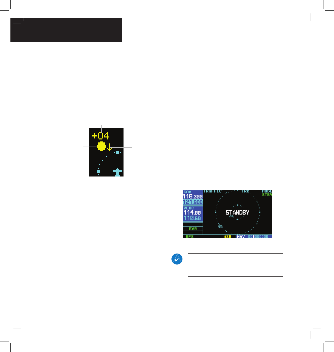
Altitude deviation (Figure 12-20) from own aircraft
altitude is displayed (in hundreds of feet) for each target
symbol. If traffic is above own aircraft altitude the
deviation is shown above the target next to a ‘+’ symbol.
If traffic is below own aircraft altitude the deviation is
shown below the target next to a ‘-’ symbol.
Altitude trend (Figure 12-20) is displayed as an up
arrow (> +500 fpm), down arrow (< -500 fpm), or no
symbol if less than 500 fpm rate in either direction.
Figure 12-20 Traffic Symbol Components
Altitude
Deviation
Altitude
Trend
Traffic
Type
Aural Alerts
A TA consists of a displayed trafc symbol (solid yellow
circle) and an aural alert. The aural alert announces
“traffic”, followed by the intruder aircraft’s position,
altitude relative to own aircraft (“high”, “low”, or “same
altitude”), and distance from own aircraft; e.g. “trafc, 12
o’clock, high, 3 miles”.
Power-up Self-Test
Check for the following test criteria on the Trafc Page
during power-up:
• If the GTS 800 passes the power-up test; and
the aircraft both has a squat switch and is on the
ground, the Standby Screen is displayed (Figure
12-21).
• If the GTS 800 passes the power-up test and the
aircraft both has a squat switch and is airborne,
the Trafc Page is displayed on the 6-nm display
range and in the normal altitude display mode.
• If the GTS 800 passes the power-up test and the
aircraft does not have a squat switch, the Standby
Screen is displayed (Figure 12-21).
• If the GTS 800 fails the power-up test (as
indicated by a FAILED screen), the GTS 800 is
inoperable, see the GTS 800 Installation Manual
for detailed information on Failure Response.
Figure 12-21 Standby Mode
NOTE: When the system is in standby, the
GTS 800 does not transmit, interrogate, or track
intruder aircraft.

GNS 430(A) Pilot’s Guide and Reference
190-00140-00 Rev. P 12-13
SECTION 12
ADDITIONAL FEATURES
Tracking intruder aircraft
1) Press the small right knob to activate the
cursor and highlight ‘STBY’.
2) Turn the small right knob to select ‘OPER’.
3) Press the ENT Key to confirm operating mode
and begin tracking intruder aircraft.
NOTE: The FAILED message is displayed when
the system detects an error that prohibits further
traffic display operation.
User-initiated Test
In addition to the power-up test, the GTS 800
performs self-tests during normal operation. A self-test
is performed once per minute to verify that the antenna
is connected. Also, a calibration is performed at varying
intervals based on time and temperature. A user-initiated
test of the GTS 800 interface can also be performed.
NOTE: A user-initiated test can only be performed
when in standby or failed mode.
Performing a user-initiated test:
1) Turn the small right knob to select the Traffic
Page.
2) From the Traffic Page, press the MENU Key to
display the Page Menu.
3) Turn the small right knob to select ‘Self
Test?’.
4) Press the ENT Key.
Switching Between Standby and Operating
Modes
The unit must be in operating mode for traffic to be
displayed. The ability to switch out of standby into operating
mode on the ground is especially useful for scanning the
airspace around the airport before takeoff. Operating Mode
is conrmed by the display of ‘OPER’ in the upper right-
hand corner of the Trafc Page (Figure 12-22).
Switching to Operating Mode from Standby
Mode:
1) Press the small right knob to activate the
cursor and highlight ‘STBY’.
2) Turn the small right knob to select ‘OPER?’.
3) Press the ENT Key to confirm and place the
GTS 800 in operating mode, the GTS 800
switches out of standby into the 6-nm display
range.
NOTE: If the aircraft has a squat switch and the
pilot does not manually switch out of standby, the
GTS 800 will automatically switch out of standby
8 to 10 seconds after takeoff.
Switching to Standby Mode from the Traffic
Page:
1) Press the small right knob to activate the
cursor and highlight ‘OPER’.
2) Turn the small right knob to select ‘STBY?’.
3) Press the ENT Key to confirm and place the
GTS 800 in standby mode.
NOTE: If the aircraft has a squat switch, STBY is
not displayed while the aircraft is airborne but
will go into standby 24 seconds after landing.
This delay allows the GTS 800 to remain out of
standby during a touch-and-go maneuver.
GNS 430(A) Pilot’s Guide and Reference 190-00140-00 Rev. P
12-14
SECTION 12
ADDITIONAL FEATURES
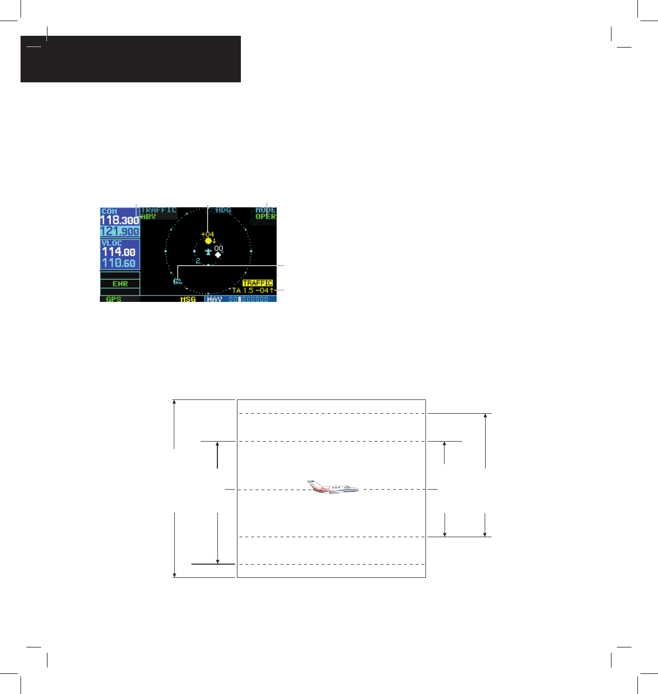
Traffic Page
Trafc can be displayed both on the Map Page (only
if heading is available) and on the Trafc Page (Figure
12-22). See the Garmin 400/500 Series Installation
Manual available at authorized Garmin service centers for
details.
Figure 12-22 Traffic Page
Altitude Display Mode Traffic
Display
Range
Traffic Advisory
(with no bearing
information)
Operating Mode
Traffic Page Display Range
The display range on the Trafc Page can be changed
at any time.
Figure 12-23 Altitude Display Modes
+2,700 ft
Not to Scale
Normal (NRM)
Below (BLW)
+2,700 ft
-9,900 ft
Above (ABV)
0 ft
+9,900 ft
Unrestricted (UNR)
0 ft
-2,700 ft
-9,000 ft
+9,000 ft
Changing the display range on the Traffic
Page:
Press the RNG Key to step through the following
range options:
• 2 nm
• 2 and 6 nm
• 6 and 12 nm
• 12 and 24 nm
Altitude Display Mode
The GTS 800 has four altitude display modes (Figure
12-23); Normal (±2,700 ft), Above (-2,700 ft to +9,000 ft),
Below (-9,000 ft to +2,700 ft), and Unrestricted (±9,900 ft).
The GTS 800 continues to track up to 30 intruder aircraft
within its maximum surveillance range, regardless of the
altitude display mode selected.
GNS 430(A) Pilot’s Guide and Reference
190-00140-00 Rev. P 12-15
SECTION 12
ADDITIONAL FEATURES
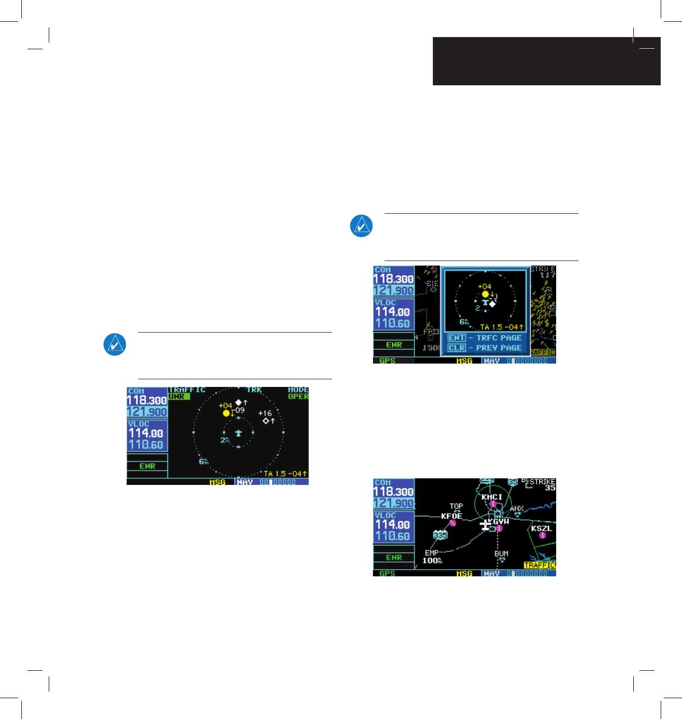
The selected altitude display mode (Figure 12-24) is
displayed in the upper left-hand corner of the Trafc Page.
The GTS 800 continues to track up to 30 intruder aircraft
within its maximum surveillance range, regardless of the
altitude display mode selected.
Changing the Altitude Display Mode:
1) From the Traffic Page, press the small right
knob to activate the cursor and highlight the
current mode (Figure 12-24).
2) Turn the small right knob to cycle through
the options. The screen changes to display
the traffic detected within the selected
altitude display range. Refer to Figure 12-23
for information regarding altitude display
ranges.
NOTE: Confirmation is not required, the mode is
changed immediately when using the small right
knob.
Figure 12-24 “UNR” Selected
3) Press the small right knob to turn the cursor
off after the selection is made.
Traffic Warning Window
When the unit is not on the trafc page and a trafc
threat is imminent, the Trafc Warning Window (Figure
12-25) is displayed, which shows a small thumbnail map.
When the Trafc Warning Window is displayed, press the
ENT Key to display the Trafc Page, or press the CLR Key
to return to the previous page.
NOTE: The Traffic Warning Window is disabled
when the aircraft ground speed is less than 30
knots or when an approach is active.
Figure 12-25 Traffic Warning Window
Map Page Traffic Banner
When a Trafc Advisory is active, the ‘Trafc’ banner
is displayed in the lower right corner of the Map Page
(Figure 12-26)
Figure 12-26 Traffic Banner
GNS 430(A) Pilot’s Guide and Reference 190-00140-00 Rev. P
12-16
SECTION 12
ADDITIONAL FEATURES
Configuring Traffic Data on the Map Page
Trafc is only displayed on the Map Page if aircraft
heading data is available. When heading is not available,
Trafc Advisories are displayed as non-bearing banners on
the Map Page. See the Garmin 400/500 Series Installation
Manual available at authorized Garmin service centers for
details.
Traffic mode allows the operator to choose which
trafc type is displayed (all trafc, trafc and proximity
advisories, or trafc advisories only). The trafc symbol
(Table 12-4) is used to depict the type of trafc.
Configuring traffic on the Map Page:
1) Turn the small right knob to select the Map
Page.
2) Press the MENU Key to display the Page
Menu.
3) Turn the small right knob to select ‘Setup
Map?’.
4) Press the ENT Key. The flashing cursor
highlights the GROUP field.
5) Turn the small right knob to select ‘Traffic’.
6) Press the ENT Key (Figure 12-27).
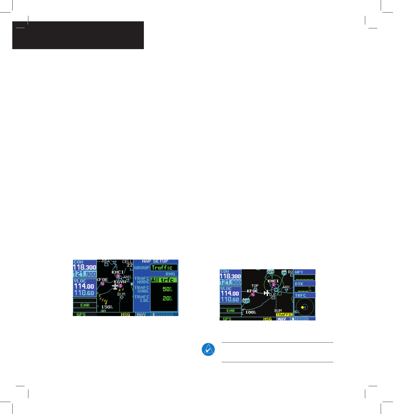
Figure 12-27 Map Setup Menu
7) Turn the large right knob to select the desired
Traffic Mode option.
8) Turn the small right knob to select the desired
option
9) Press the ENT Key. Repeat steps 7-9 for Traffic
Symbol and Traffic Label.
10) Return to the Map Page by pressing the CLR
Key.
Thumbnail Traffic on Map Page
Traffic in a thumbnail format can be displayed in any
of the three data elds on the right side of the Map Page
(Figure 12-28).
Displaying Thumbnail Traffic on the Map
Page
1) Turn the small right knob to select the Map
Page.
2) Press the MENU Key to display the Page
Menu.
3) Turn the small right knob to select ‘Change
Fields?’.
4) Press the ENT Key.
5) Turn the large right knob to select one of the
three fields.
6) Turn the small right knob to select ‘TRFC’ from
the Select Field Type List.
7) Press the ENT Key. (Figure 12-28)
Figure 12-28 Thumbnail Traffic on Map Page
NOTE: The thumbnail range defaults to 6 nm and
cannot be changed.

GNS 430(A) Pilot’s Guide and Reference
190-00140-00 Rev. P 12-17
SECTION 12
ADDITIONAL FEATURES
Highlighting Traffic Data Using Map Panning
Another map page function is panning, which allows
changing the map beyond its current limits without
adjusting the map scale. Select the panning function by
pressing the small right knob, a target pointer ashes on
the map display (Figure 12-29). Also a window appears at
the top of the map display showing the latitude/longitude
position of the pointer, and the bearing and distance to
the pointer from the present position.
Selecting the panning function and panning
the map display:
1) Press the small right knob to activate the
panning target pointer (Figure 12-29).
Figure 12-29 Panning the Map Display
2) Turn the small right knob clockwise to move
up, or counterclockwise to move down.
3) Turn the large right knob clockwise to move
right, or counterclockwise to move left.
4) To cancel the panning function and return to
the present position, press the small right
knob.
When the target pointer is placed on trafc, the trafc
range and altitude deviation are displayed (Figure 12-29).
The traffic is identified as:
• TA: Trafc Advisory
• PA: Proximity Advisory
• TRFC: Other Trafc