Garmin 0104450 LICENSED NON-BROADCAST TRANSMITTER (TAS) AND TRAFFIC ALERT & COLLISION AVOIDANCE SYSTEM (TCAS) PROCESSOR User Manual coverRev4TP
Garmin International Inc LICENSED NON-BROADCAST TRANSMITTER (TAS) AND TRAFFIC ALERT & COLLISION AVOIDANCE SYSTEM (TCAS) PROCESSOR coverRev4TP
Garmin >
Contents
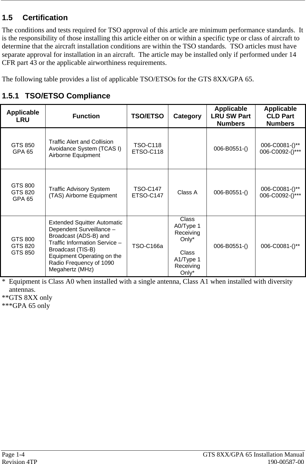
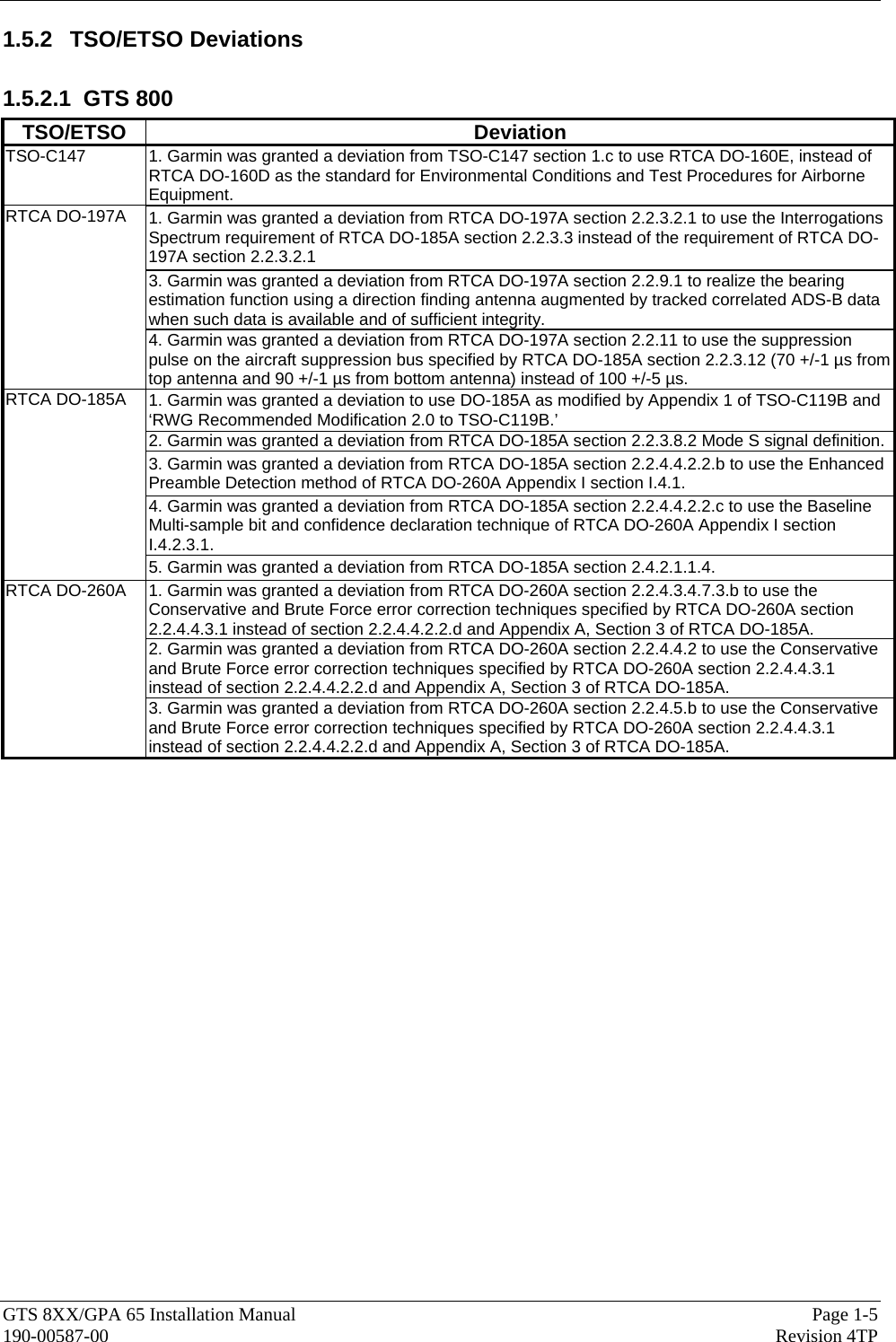
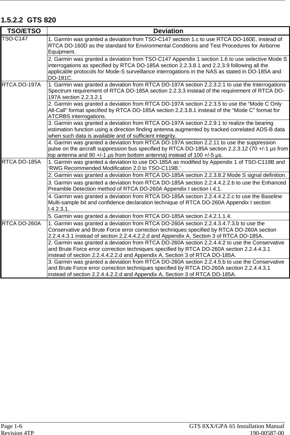
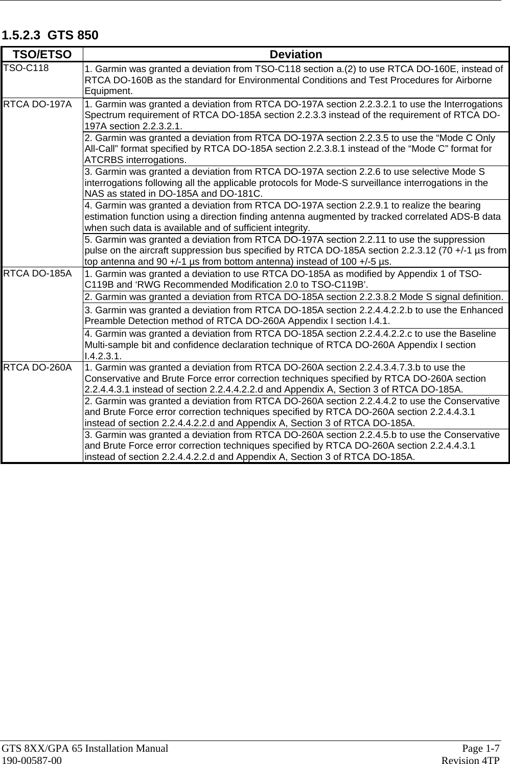
- 1. Users Manual 1
- 2. Users Manual 2
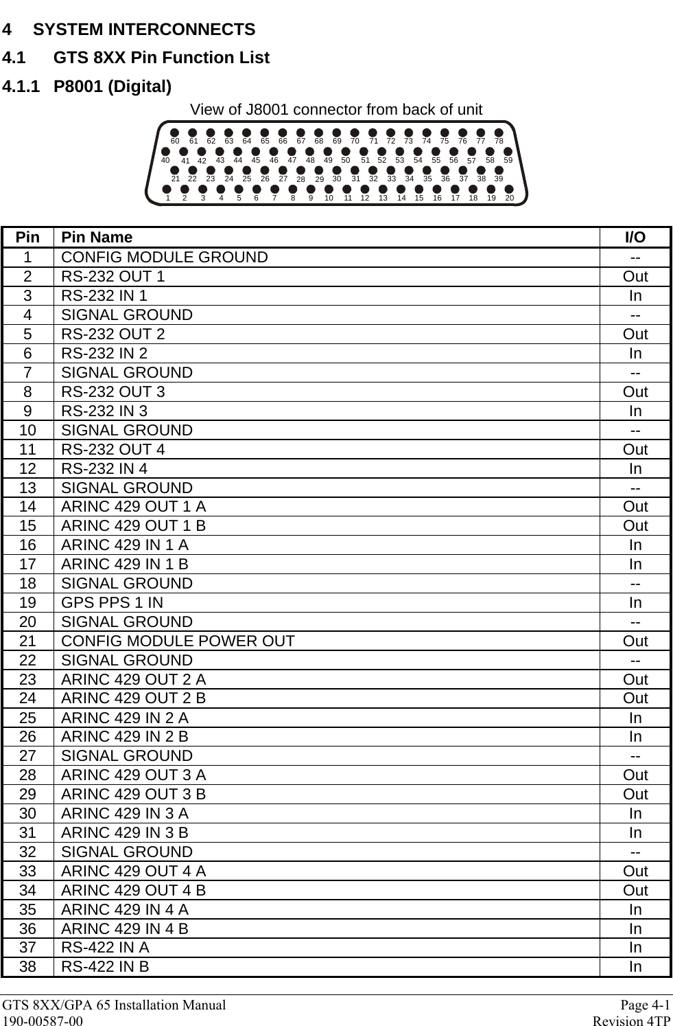
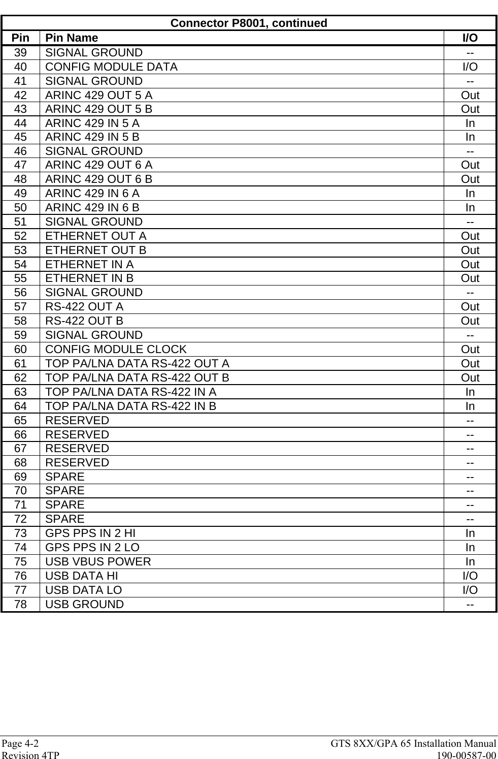
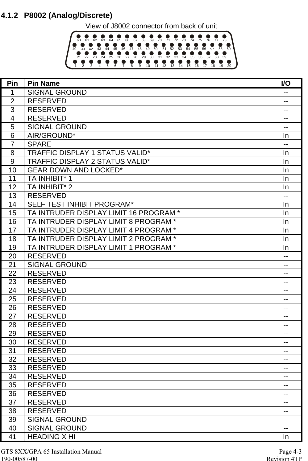
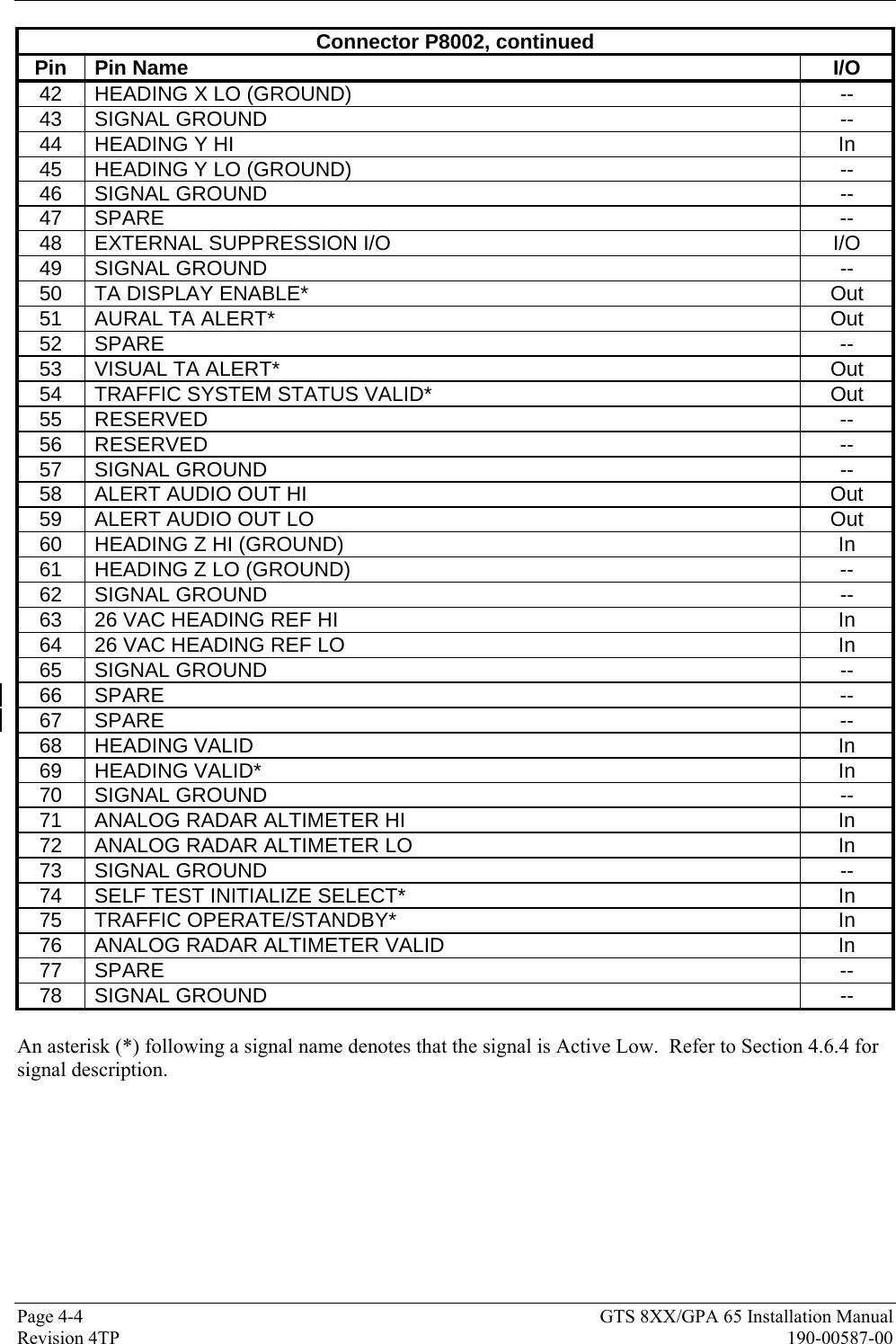
Users Manual 2

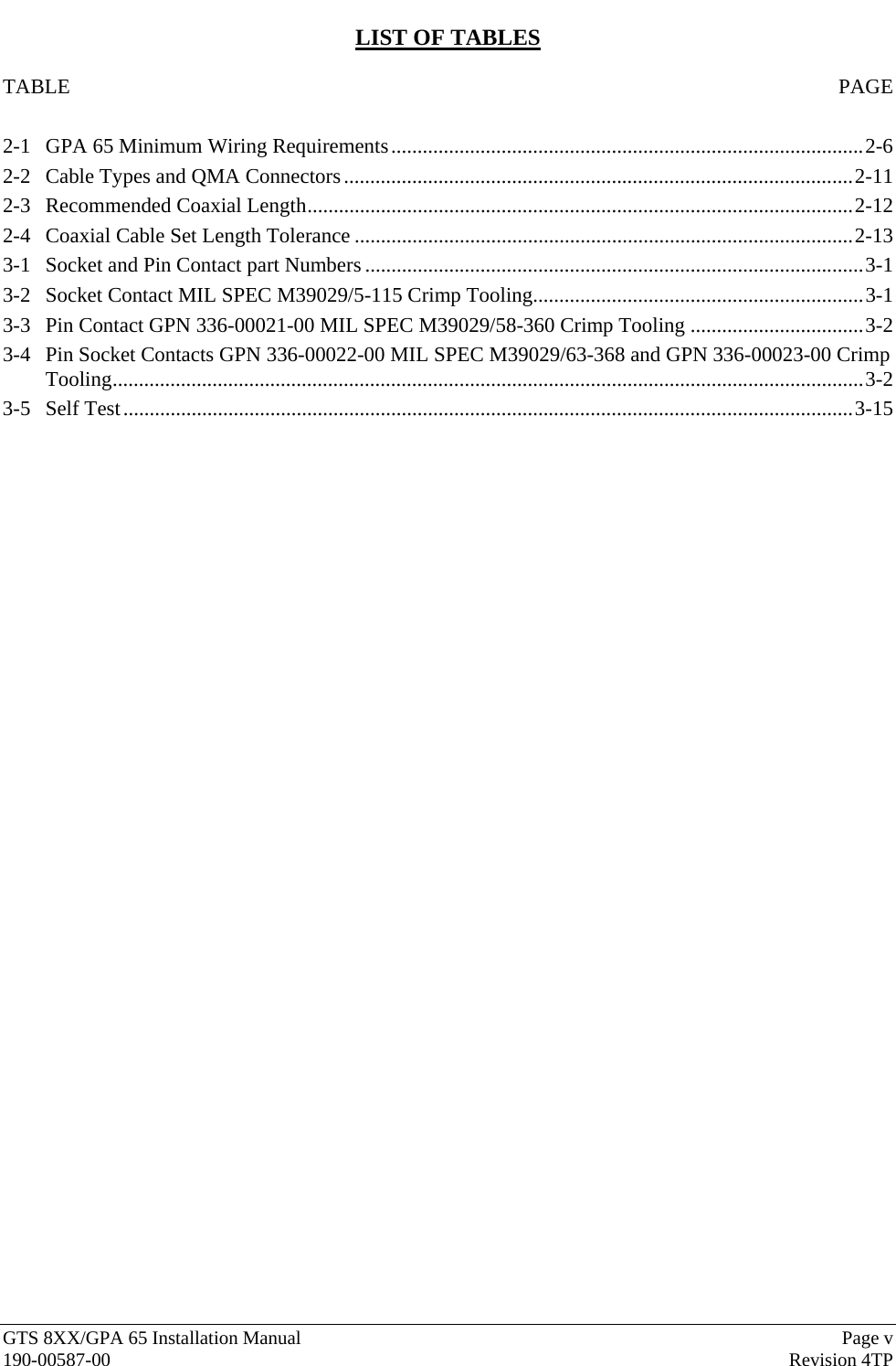
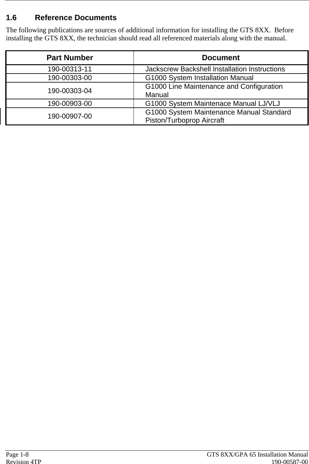

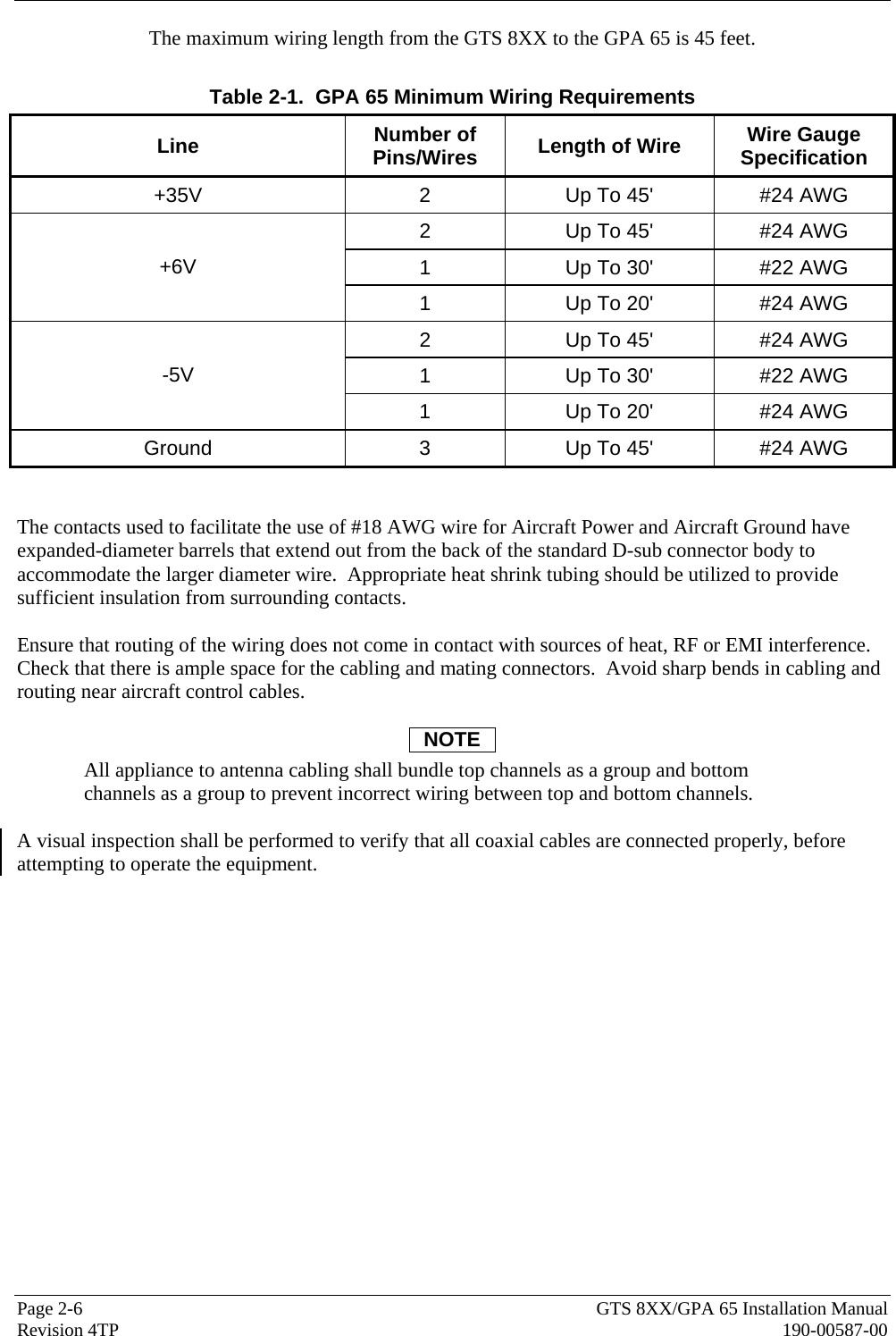
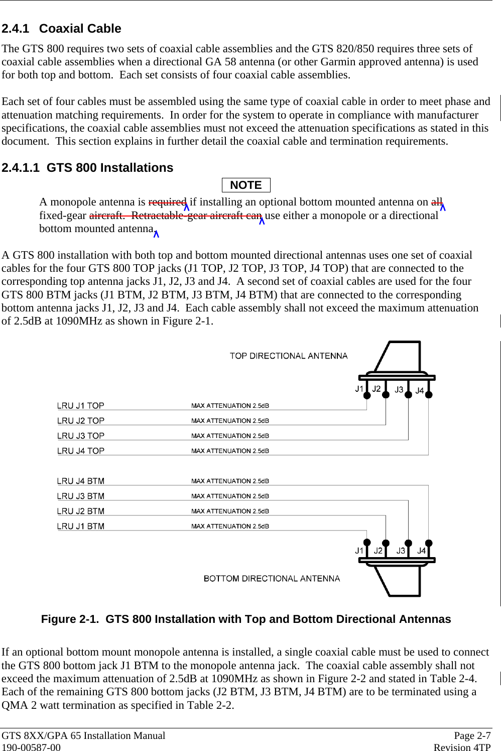
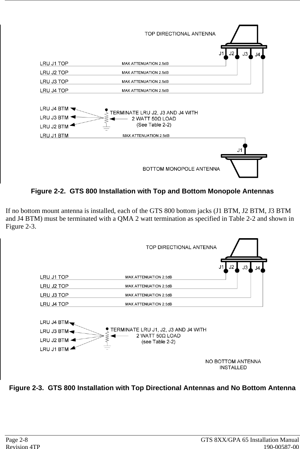
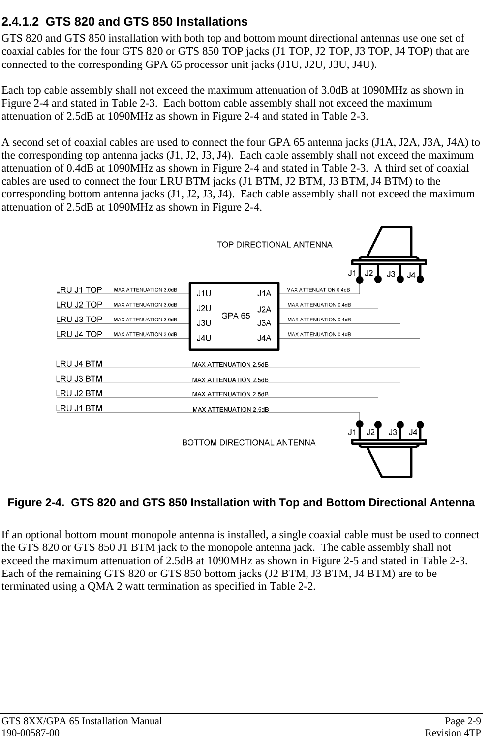
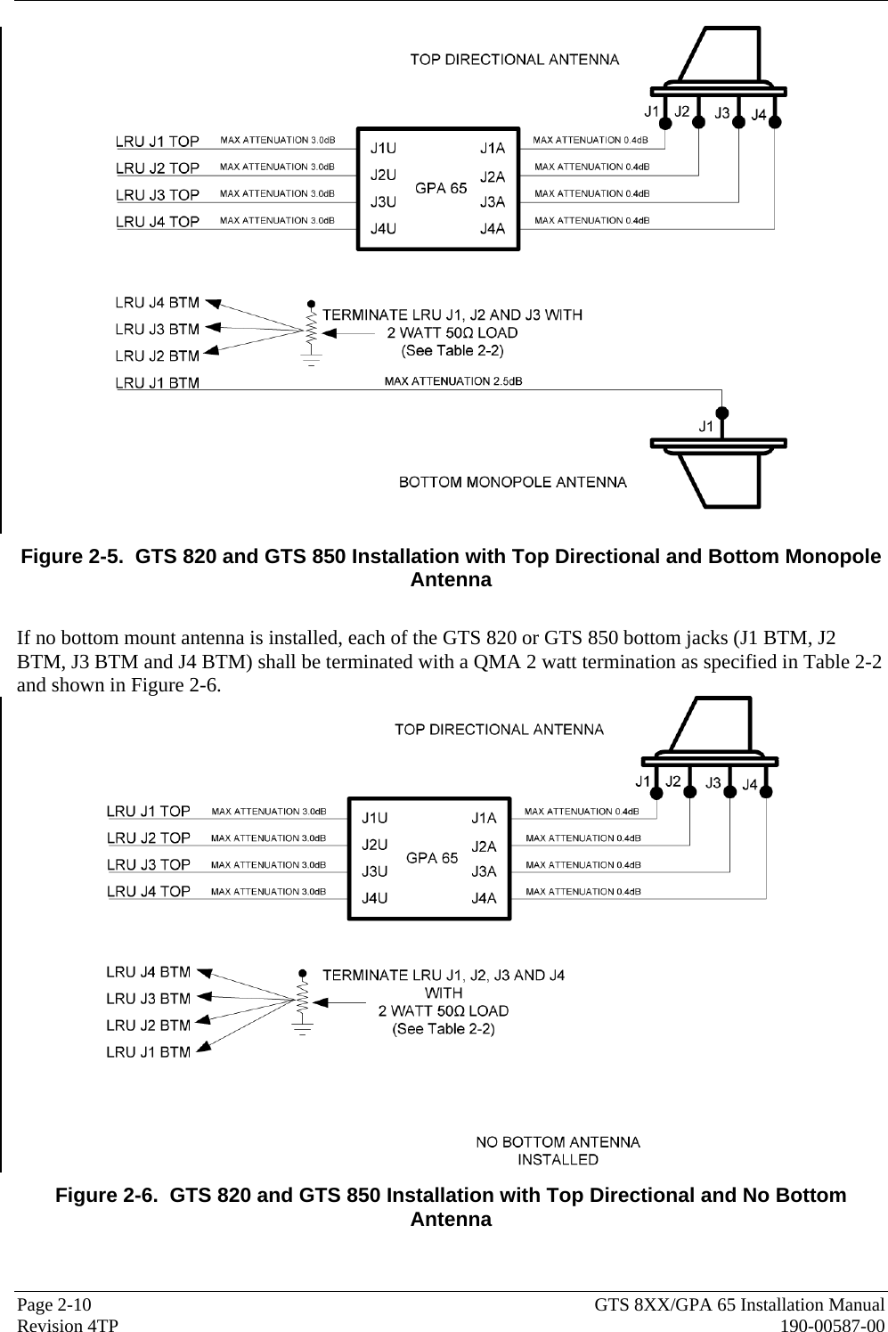
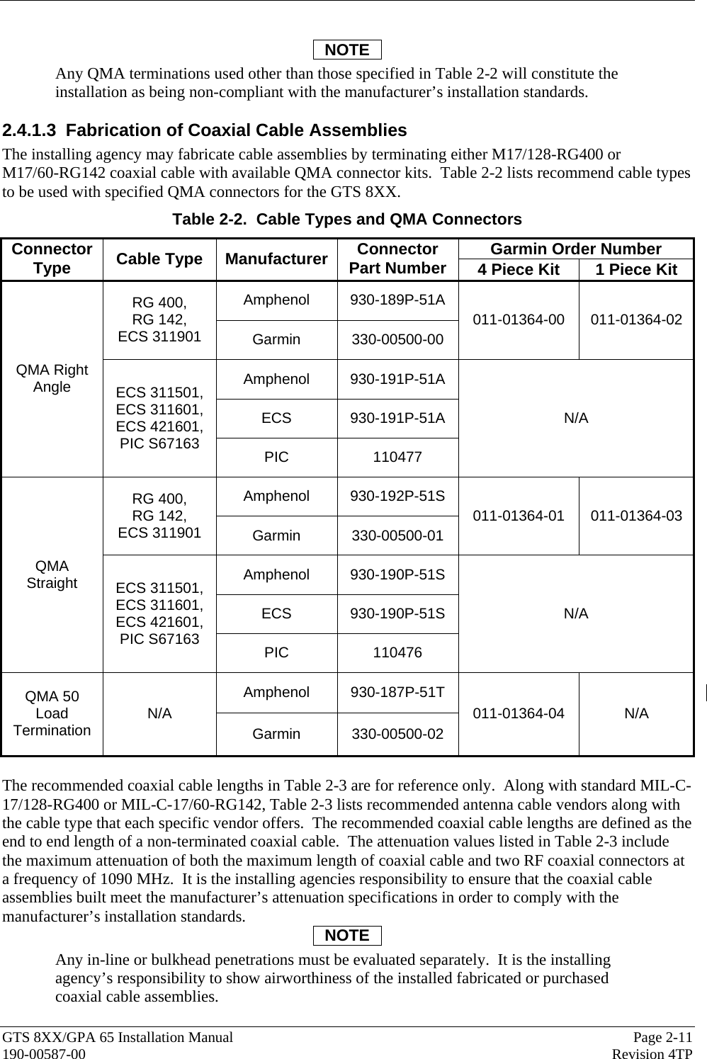
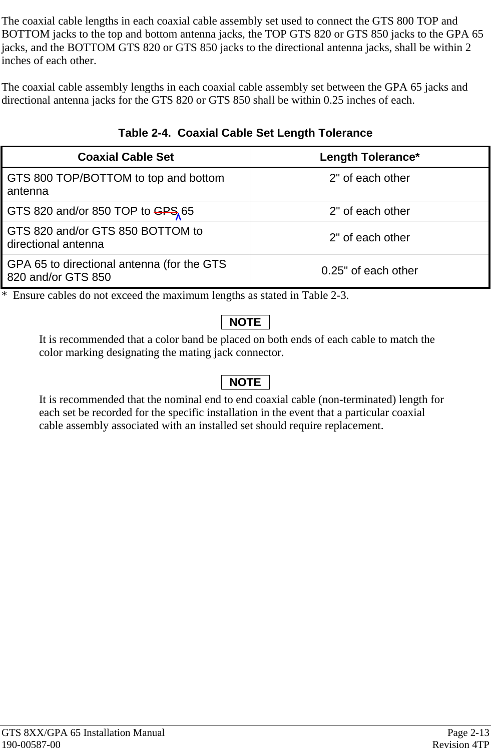
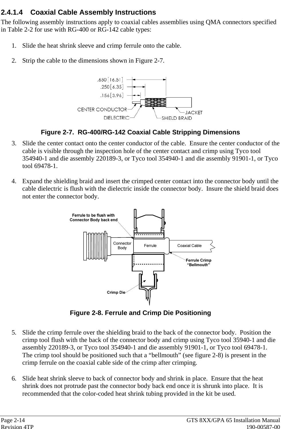
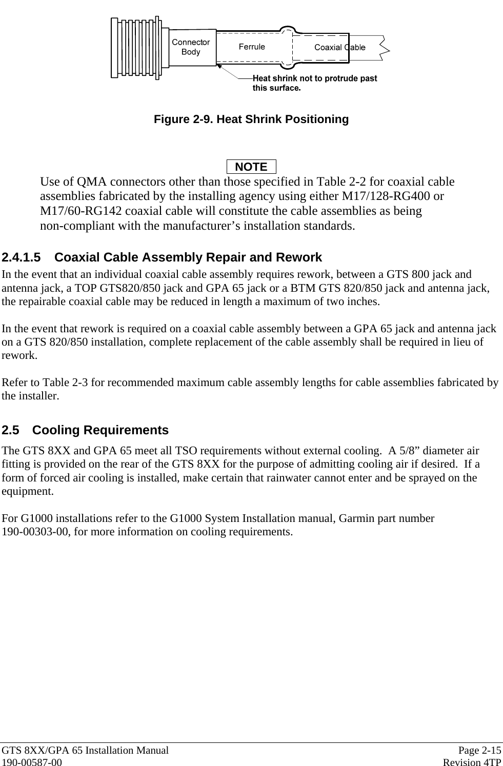
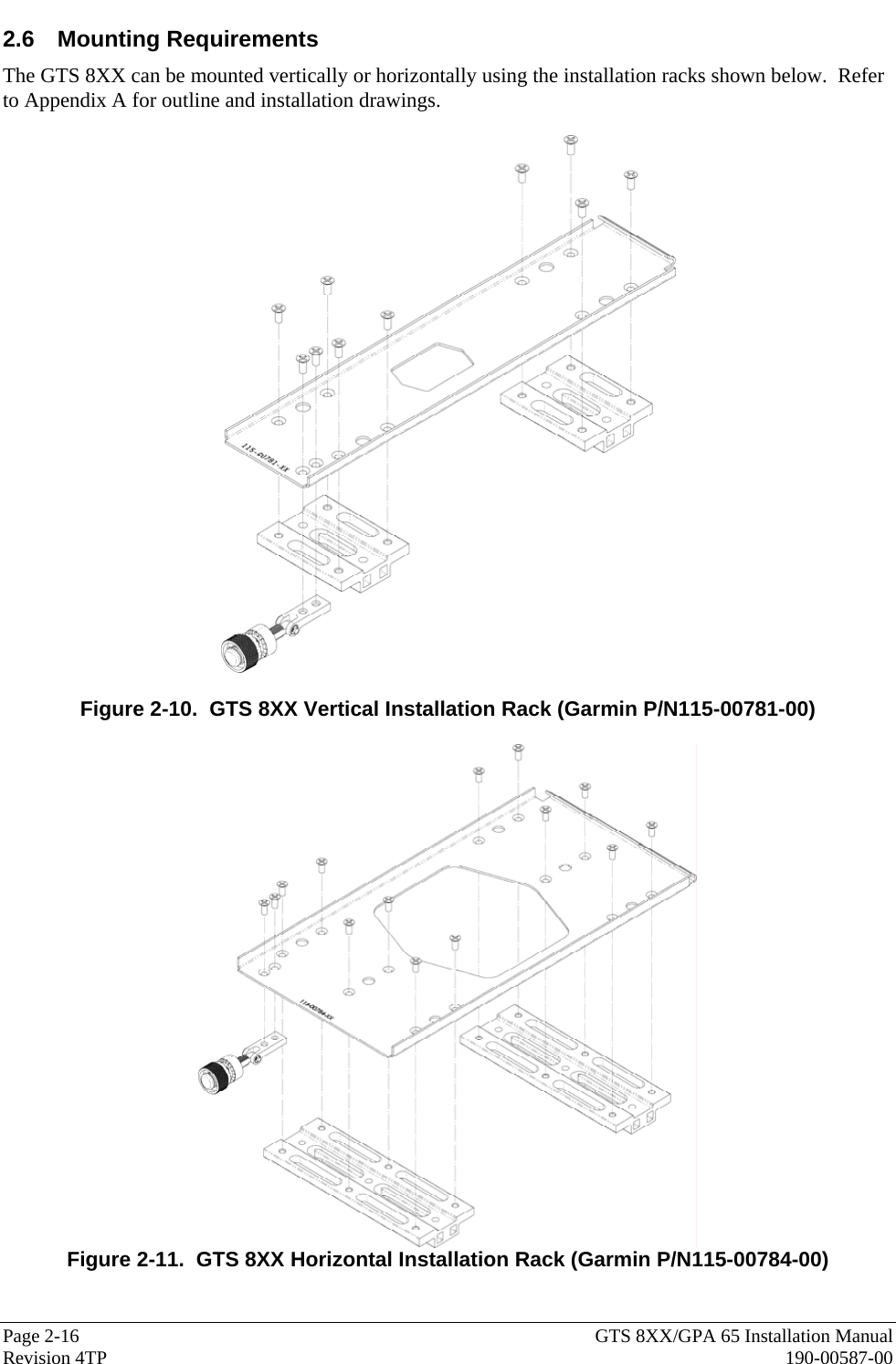
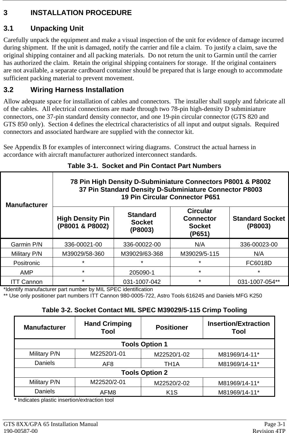
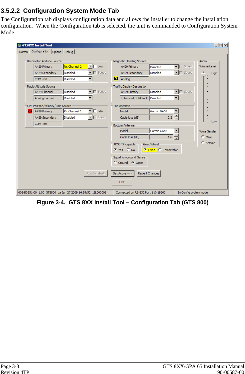
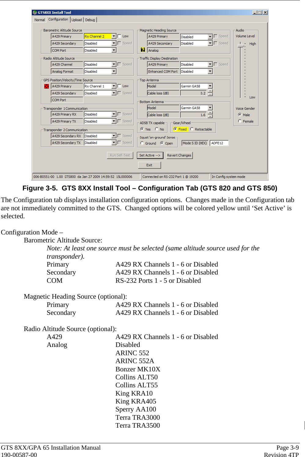
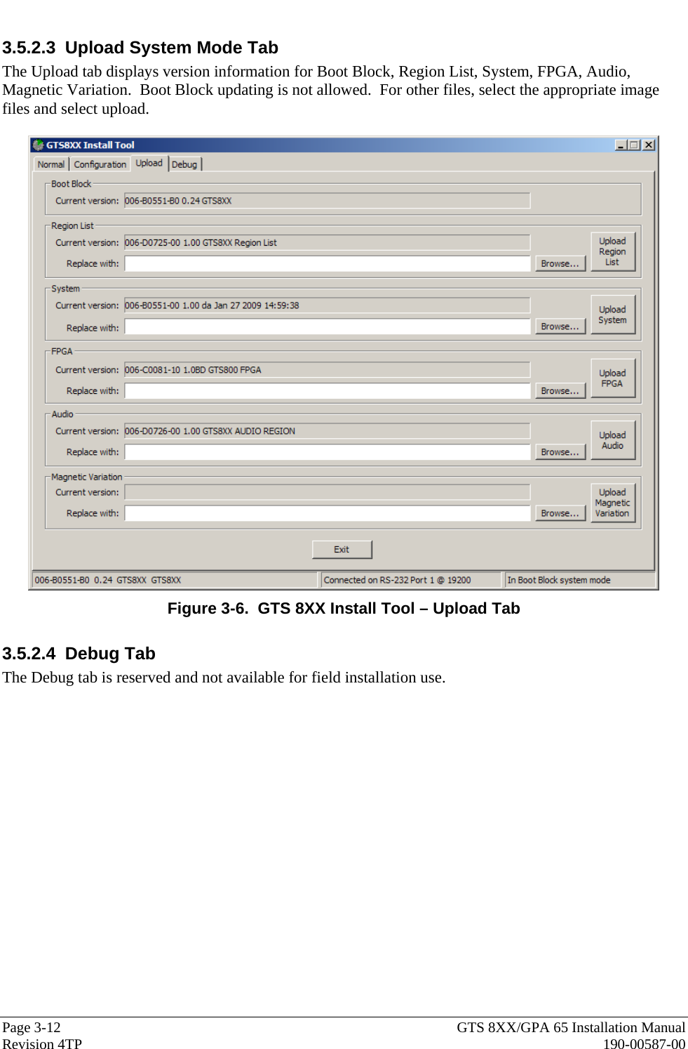
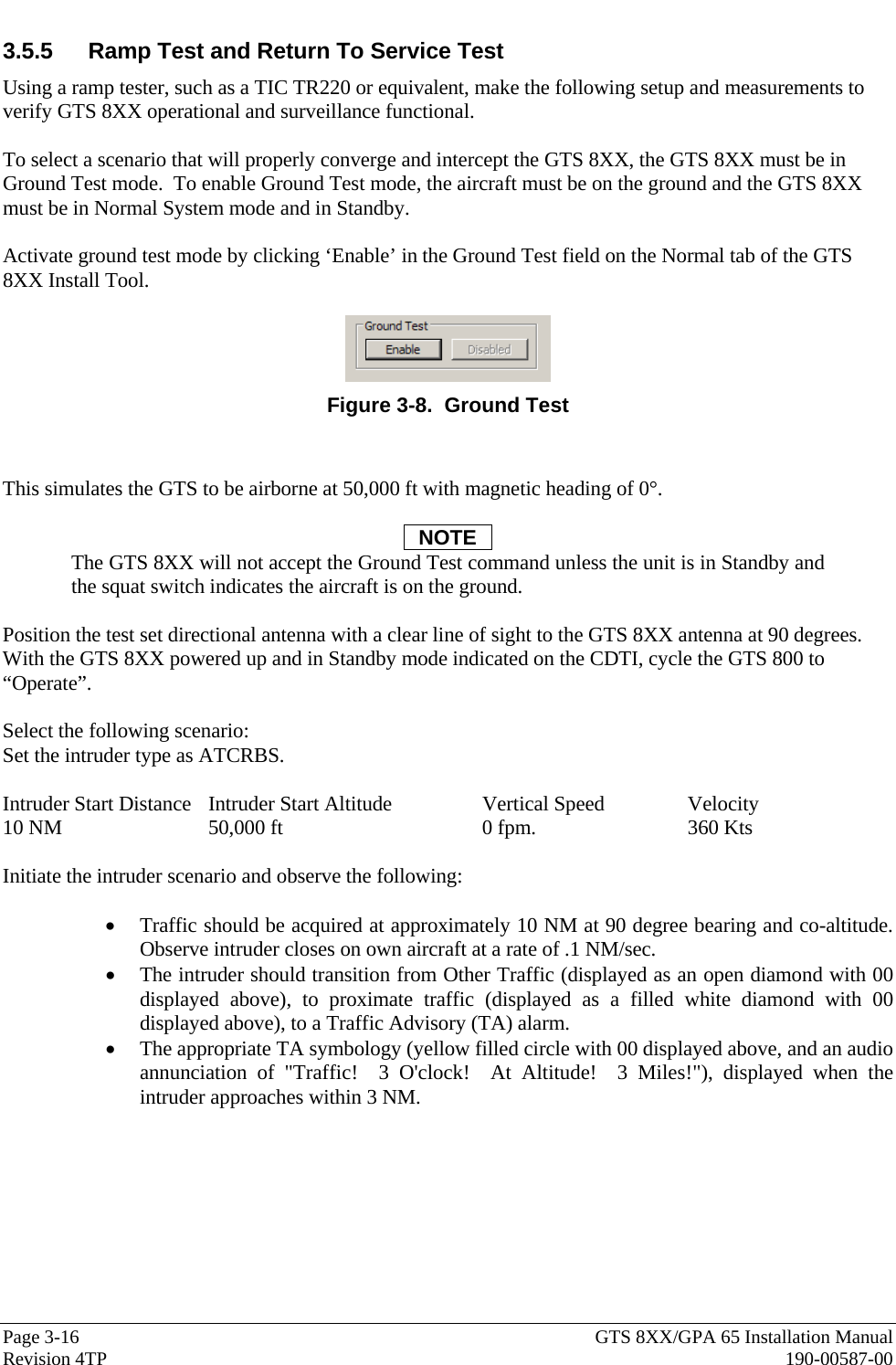
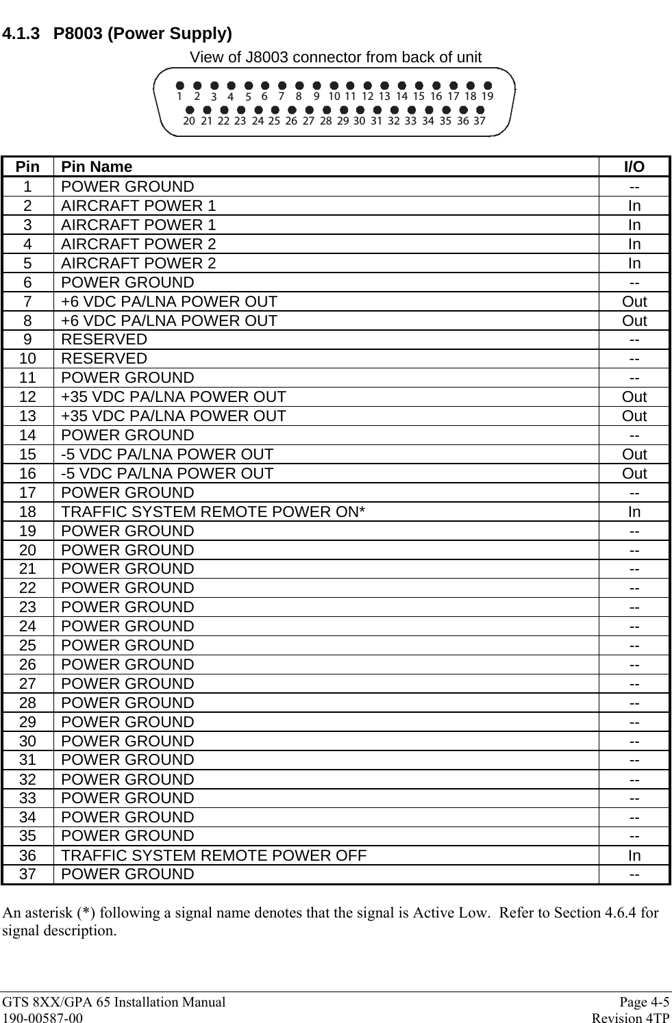
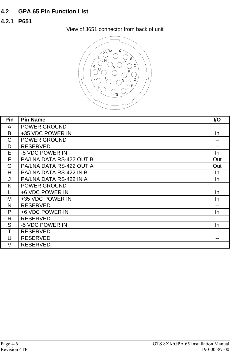
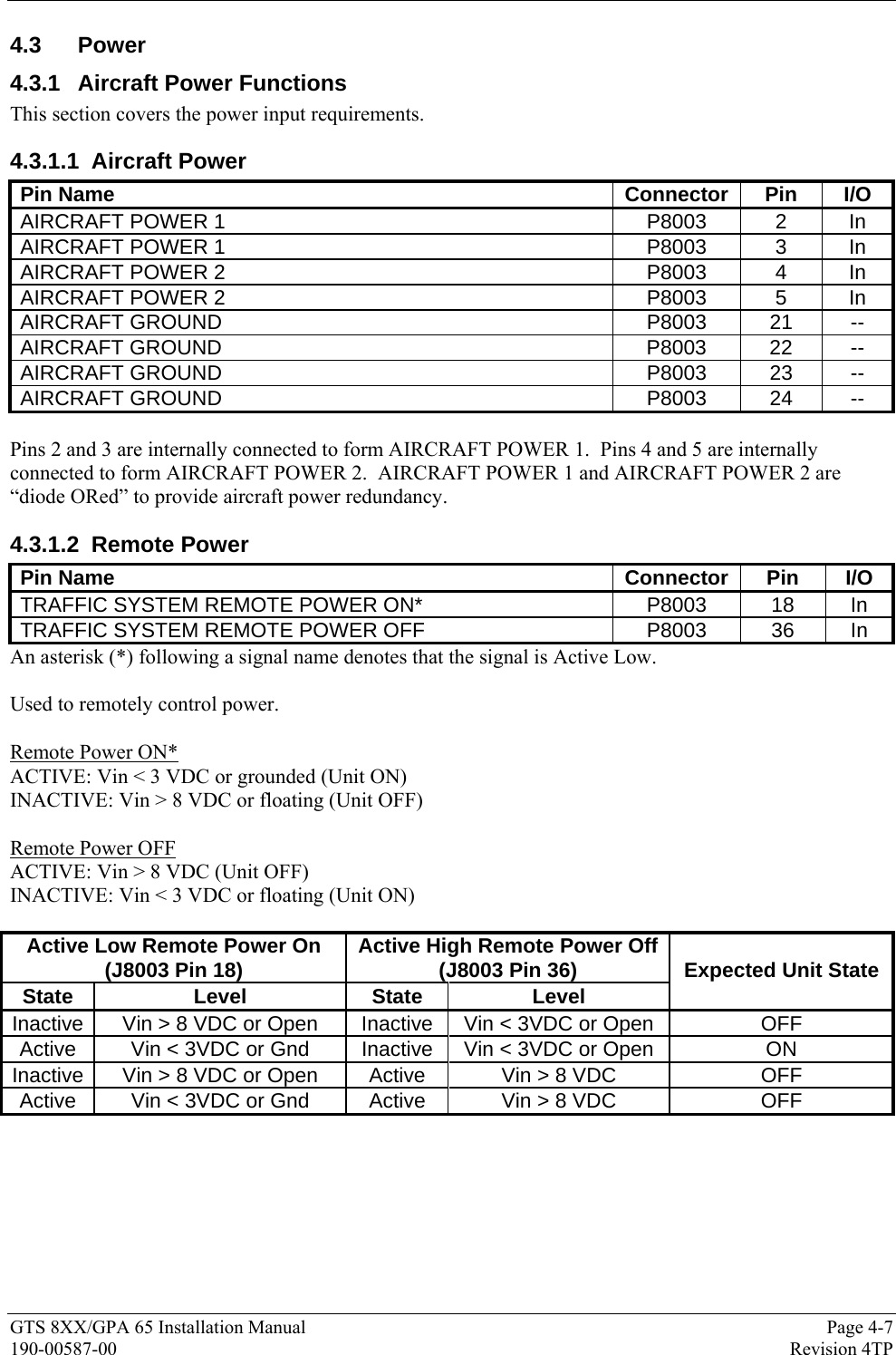
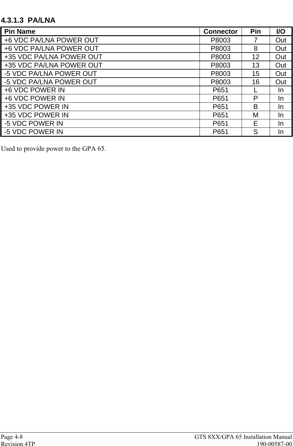
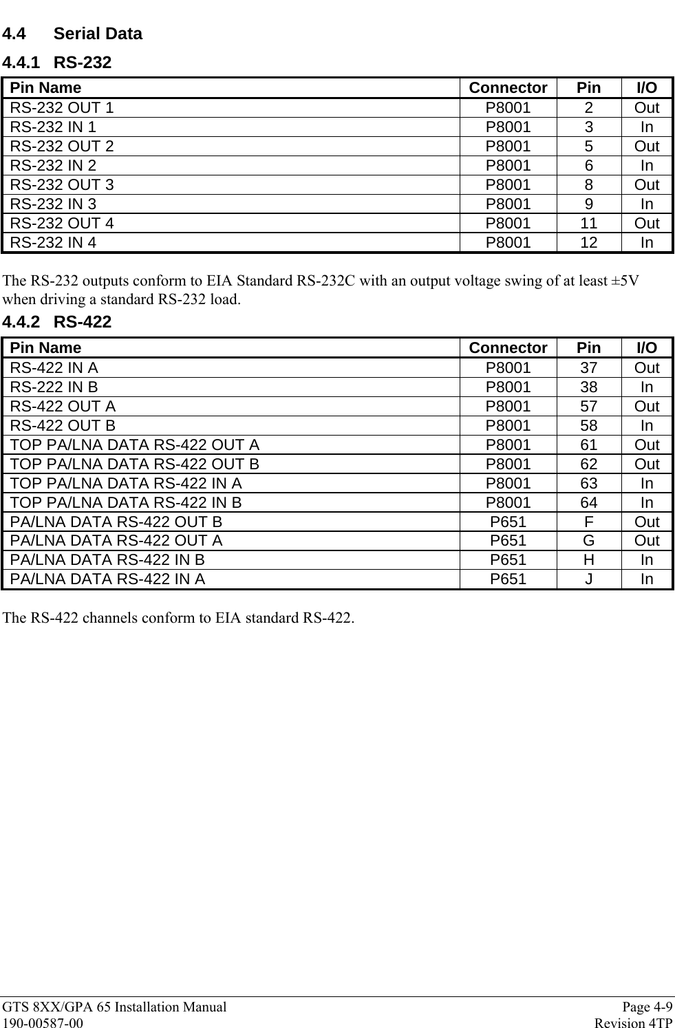
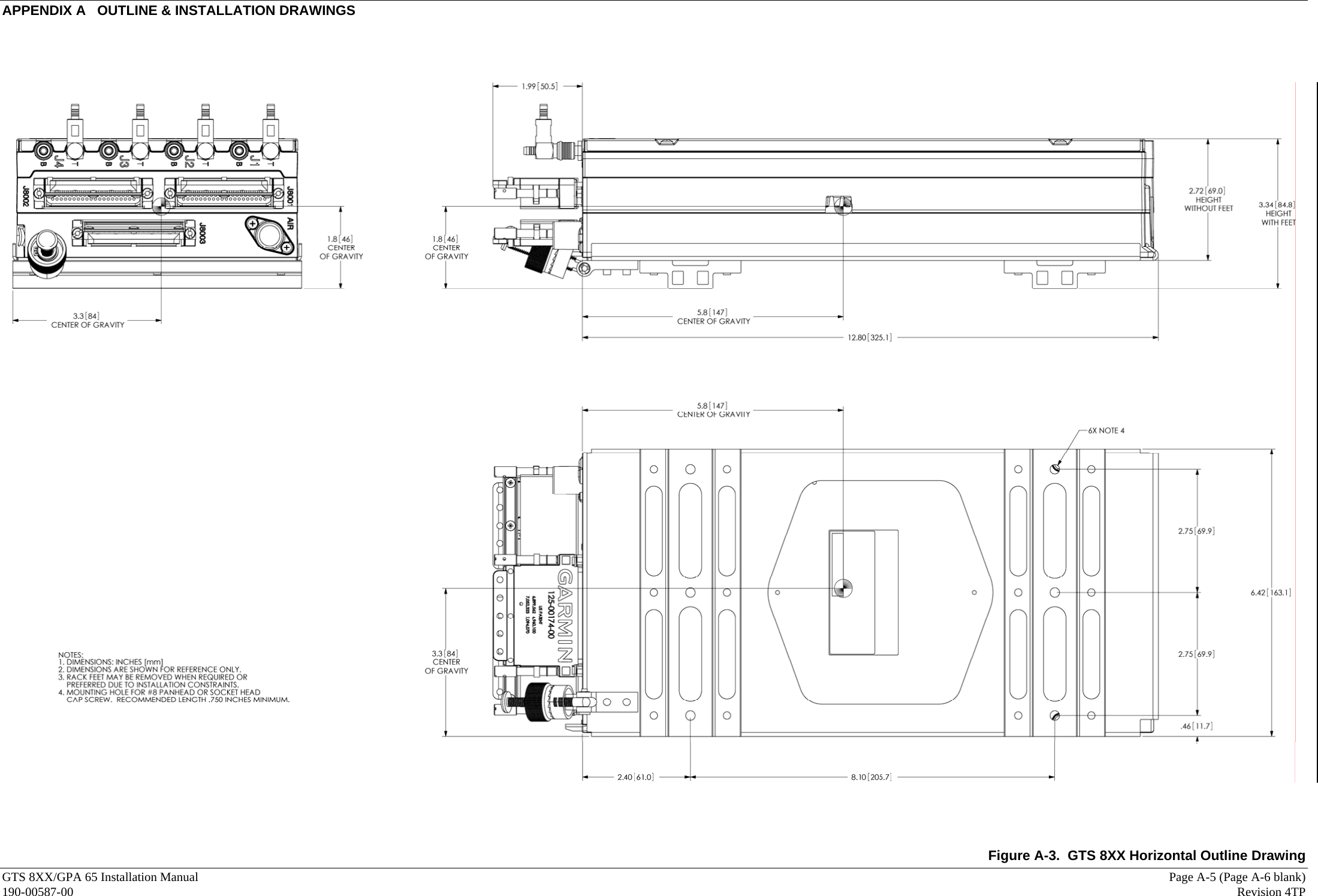
![Page 2-12 GTS 8XX/GPA 65 Installation Manual Revision 4TP 190-00587-00 Table 2-3. Recommended Coaxial Length Attenuation Loss of 0.4 dB Loss of 0.5 dB Loss of 1.5 dB Loss of 2.0 dB Loss of 2.5 dB Loss of 3.0 dB Attenuation (dB/100ft) ECS Type PIC Type MIL-C-17 Type RG Type 1' 10" [0.55m] 2' 7" [0.79m] 9' 0" [2.74m] 12' 0" [3.66m] 15' 5" [4.70m] 18' 8" [5.68m] 15.5 M17/128-RG400 RG-400 2' 0" [0.60m] 2' 9" [0.84m] 10' 5" [2.94m] 13' 0" [3.96m] 16' 6" [5.03m] 20' 1" [6.12m] 14.45 M17/60-RG142 RG-142 2' 5" [0.74m] 3' 4" [1.02m] 11' 6" [3.50m] 15' 5" [4.70m] 19' 6" [5.94m] 23' 10" [7.26m] 12.16 311901 3' 3" [0.99m] 4' 6" [1.37m] 15' 8" [4.77m] 21' 0" [6.40m] 26' 8" [8.13m] 32' 7" [9.93m] 8.93 421601 3' 5" [1.04m] 4' 6" [1.37m] 16' 1" [4.90m] 21' 5" [6.55m] 27' 6" [8.38m] 33' 6" [10.21m] 8.7 311601 M17/127-RG393 RG-393 4' 2" [1.27m] 5' 7" [1.70m] 19' 8" [5.99m] 26' 5" [8.05m] 33' 5" [10.19m] 40' 10" [12.44m] 7.12 311501 4' 0" [1.21m] 5' 5" [1.60m] 18' 5" [5.61m] 25' 0" [7.62m] 31' 6" [9.60m] 38' 3" [11.65m] 7.5 S67163 Vendor: Electronic Cable Specialists Vendor: PIC Wire and Cable 5300 W. Franklin Drive Franklin, WI 53132 Tel: 800-327-9473 414-421-5300 Fax: 414-421-5301 N53 W24747 S Corporate Circle Sussex, WI 53089-0330 Tel: 800-742-3191 262-246-0500 Fax: 262-246-0450 Supplier Information www.ecsdirect.com www.picwire.com See current issue of Qualified Products List QPL-17. RG types are obsolete and are shown for reference only; replaced by M17 type numbers.](https://usermanual.wiki/Garmin/0104450.Users-Manual-2/User-Guide-1159318-Page-30.png)