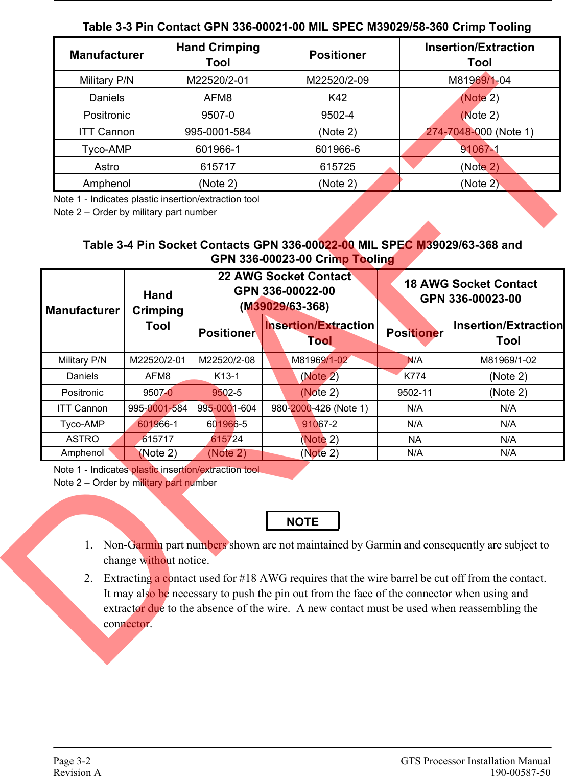
Garmin 0104455 LICENSED NON-BROADCAST TRANSMITTER (TAS) AND TRAFFIC ALERT & COLLISION AVOIDANCE SYSTEM (TCAS) PROCESSOR MHz User Manual 190 00587 50
Garmin International Inc LICENSED NON-BROADCAST TRANSMITTER (TAS) AND TRAFFIC ALERT & COLLISION AVOIDANCE SYSTEM (TCAS) PROCESSOR MHz 190 00587 50
Garmin >
Users Manual


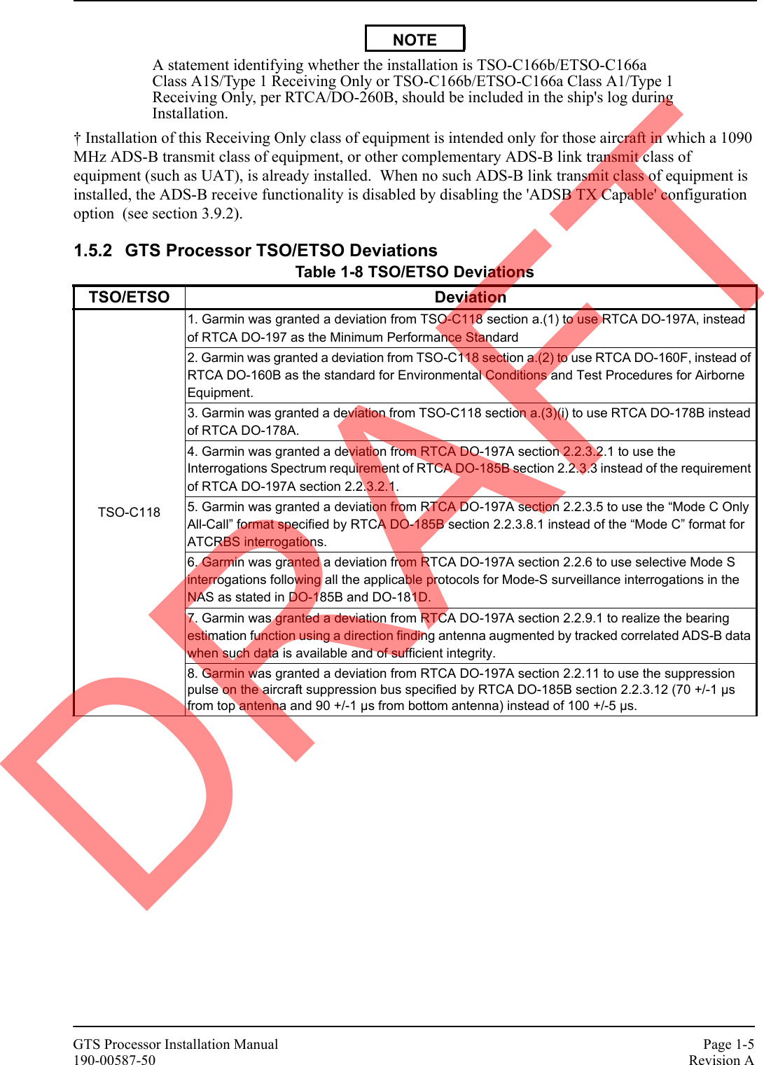


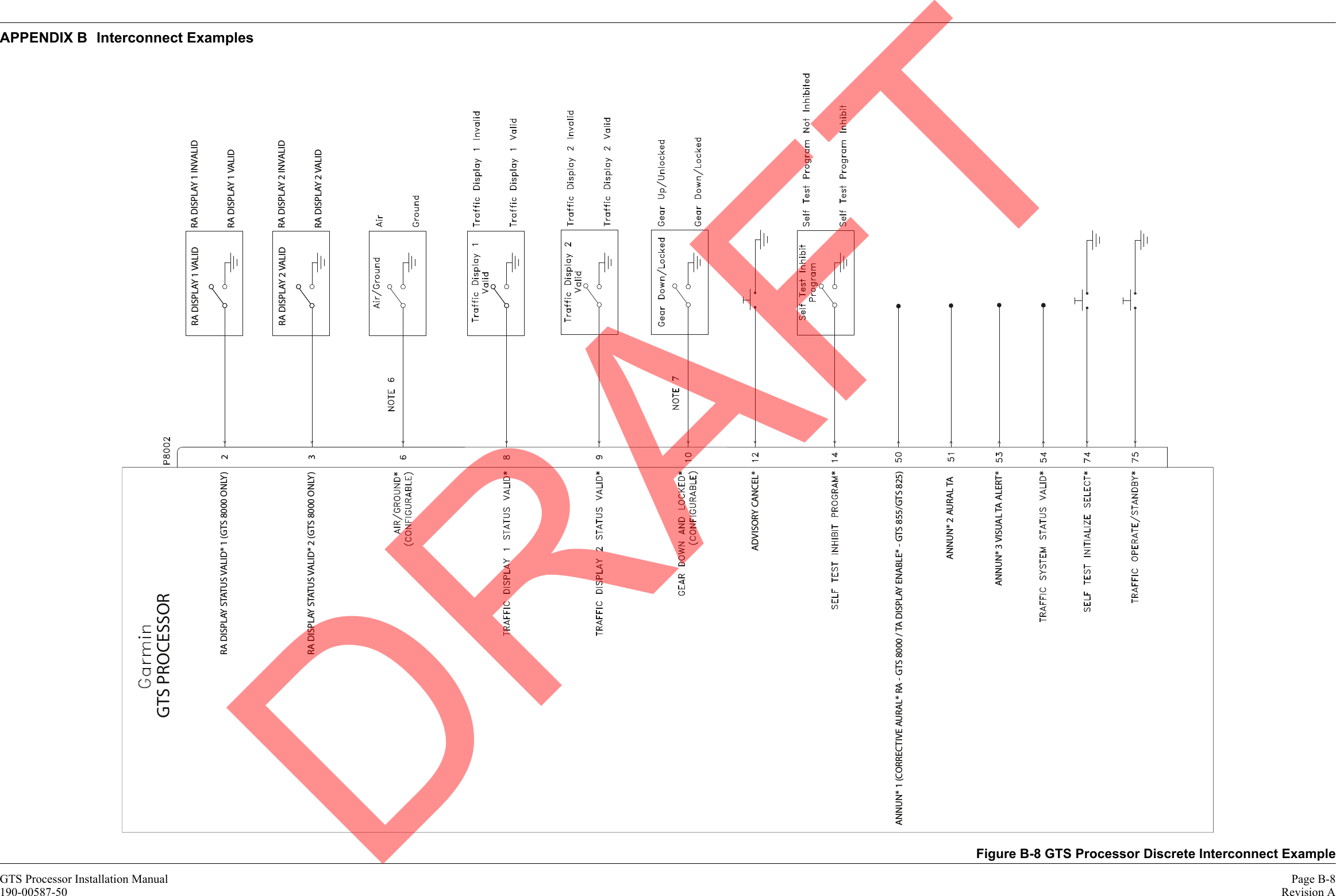
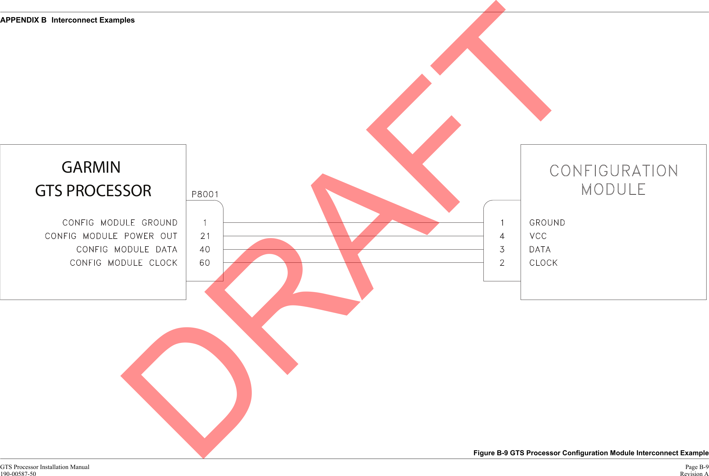
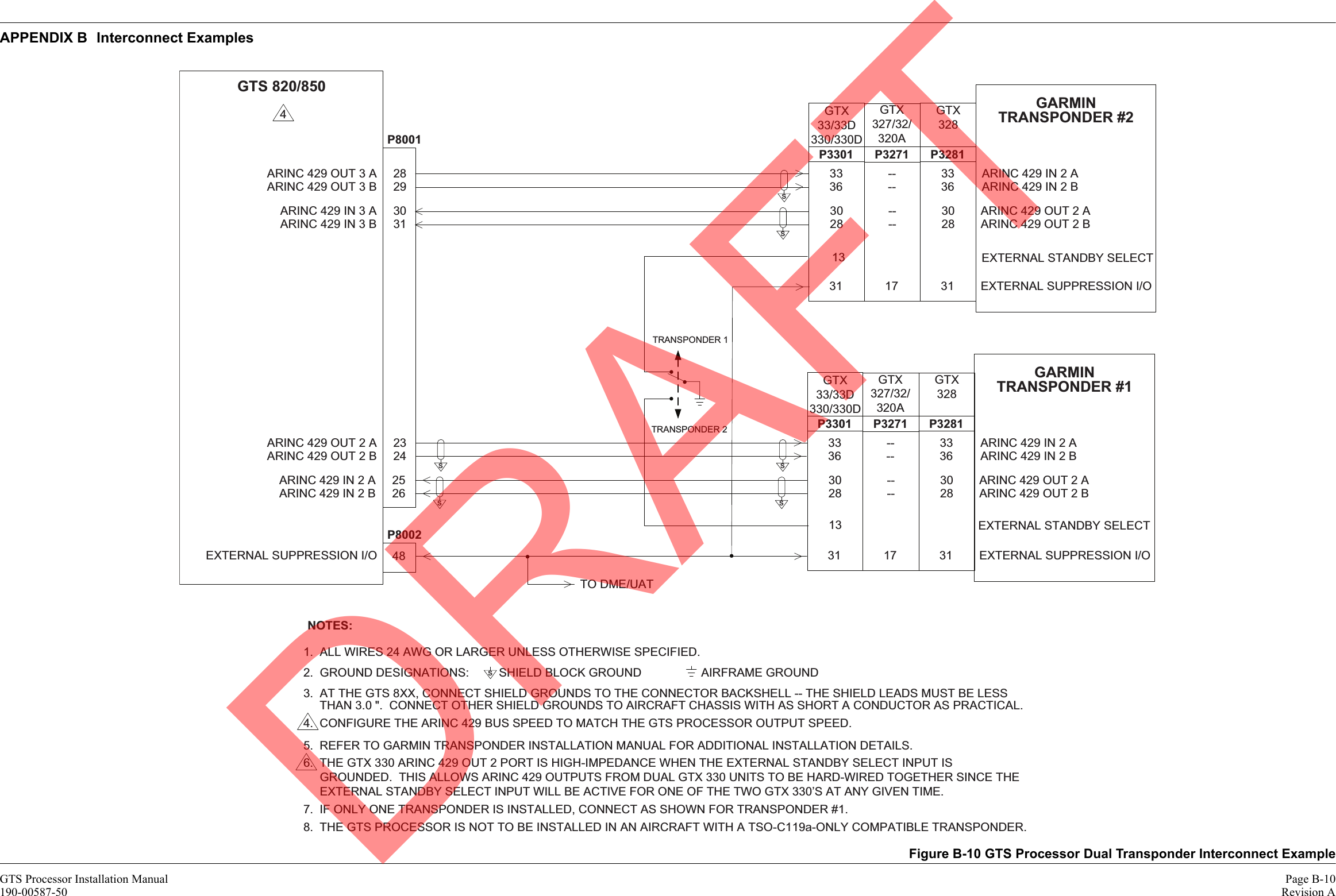
![GTS Processor Installation Manual Page 2-7190-00587-50 Revision A*The “Max Terminated Cable Attenuation” values listed include the maximum attenuation of both the maximum length of coaxial cable and two RF coaxial connectors at a frequency of 1090 MHz.**Actual cable lengths may vary depending on manufacturer’s cable attenuation and connector specifications.Table 2-7 Recommended Coaxial LengthMax Terminated Cable Attenuation(including connector loss)*Max Cable Attenuation(dB/100ft)ECS Type [1]PIC Type [2]MIL-C-17 Type [3]RG Type [4]Loss of 0.5 dBLoss of 1.5 dBLoss of 2.0 dBLoss of 2.5 dBLoss of 3.0 dBMax Coaxial Cable Lengths**2' 2"[0.66m]7' 8"[2.34m]10' 7"[3.23m]13' 6"[4.11m]16' 5"[5.00m] 17.2 M17/128-RG400 RG-4002' 3"[0.69m]8' 0"[2.44m]11' 0"[3.35m]14' 0"[4.27m]17' 0"[5.18m] 16.7 S832042' 5"[0.74m]8' 6"[2.59m]11' 9"[3.58m]15' 0"[4.57m]18' 3"[5.56m] 15.5 M17/60-RG142 RG-1423' 0"[0.91m]10' 7"[3.23m]14' 7"[4.45m]18' 7"[5.66m]22' 7"[6.88m] 12.5 3119013' 2"[0.97m]10' 11"[3.33m]15' 0"[4.57m]19' 2"[5.84m]23' 3"[7.09m] 12.2 S441913' 3"[0.99m]11' 4"[3.45m]15' 6"[4.72m]19' 9"[6.02m]24' 0"[7.32m] 11.8 S441934' 3"[1.30m]15' 0"[4.57m]20' 6"[6.25m]26' 2"[7.98m]31' 9"[9.68m] 8.9 3116015' 0"[1.52m]17' 9"[5.41m]24' 5"[7.44m]31' 0"[9.45m]37' 10"[11.53m] 7.5 S671635' 1"[1.55m]18' 0"[5.49m]24' 8"[7.52m]31' 6"[9.60m]38' 3"[11.66m] 7.4 311501[1] Vendor: Electronic Cable Specialists 5300 W Franklin Drive, Franklin, WI 53132 Telephone: 800.327.9473 or 414.421.5300 Fax: 414.421.5301 Website: www.ecsdirect.com[2] Vendor: PIC Wire and Cable N53 W24747 S Corporate Circle, Sussex, WI 53089-0330 Telephone 800.742.3191 or 262.246.0500 Fax: 262.246.0450 Website: www.picwire.com[3] See current issue of Qualified Products List, QPL-17.[4] RG types are obsolete and are shown for reference only; replaced by M17 type numbers.DRAFT](https://usermanual.wiki/Garmin/0104455/User-Guide-1616455-Page-27.png)


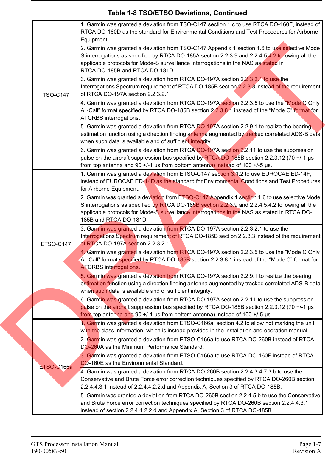
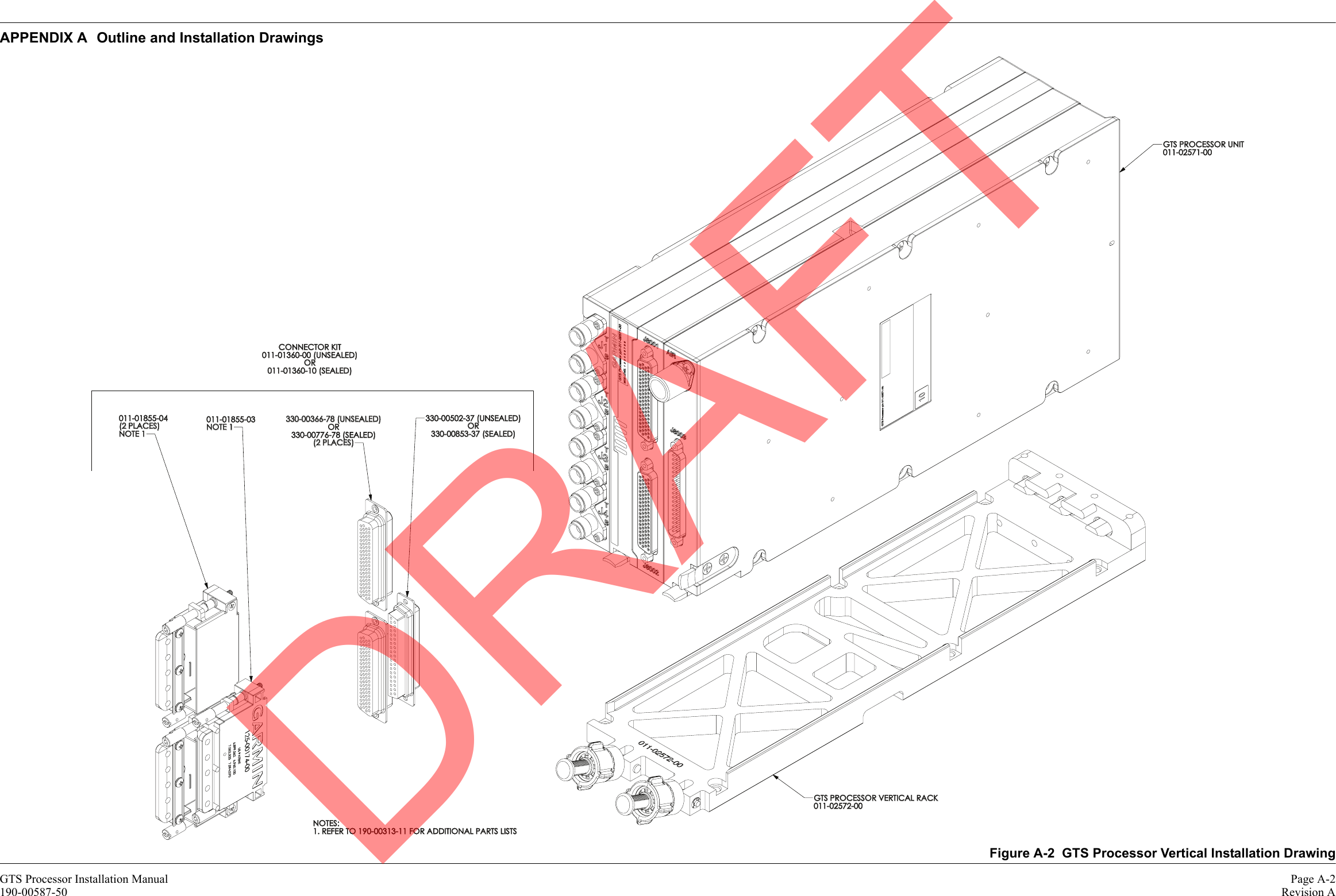
![GTS Processor Installation Manual Page A-1190-00587-50 Revision AAPPENDIX A Outline and Installation DrawingsFigure A-1 GTS Processor Vertical Outline Drawing1.99 50.56.74171.113.49 342.5CENTER OF GRAVITYTBDGRAVITYTBDCENTER OF.62515.887.00177.8 4.375111.133.32 84.23.67 93.1.18 4.4CENTER OF GRAVITYTBDGRAVITYTBDCENTER OF6X NOTE 3GRAVITYTBDCENTER OFGRAVITYTBDCENTER OFNOTES:DIMENSIONS: INCHES [mm]1.DIMENSIONS ARE SHOWN FOR REFERENCE ONLY.2.MOUNTING HOLE FOR FOR #8 PANHEAD SCREW.3.DRAFT](https://usermanual.wiki/Garmin/0104455/User-Guide-1616455-Page-69.png)
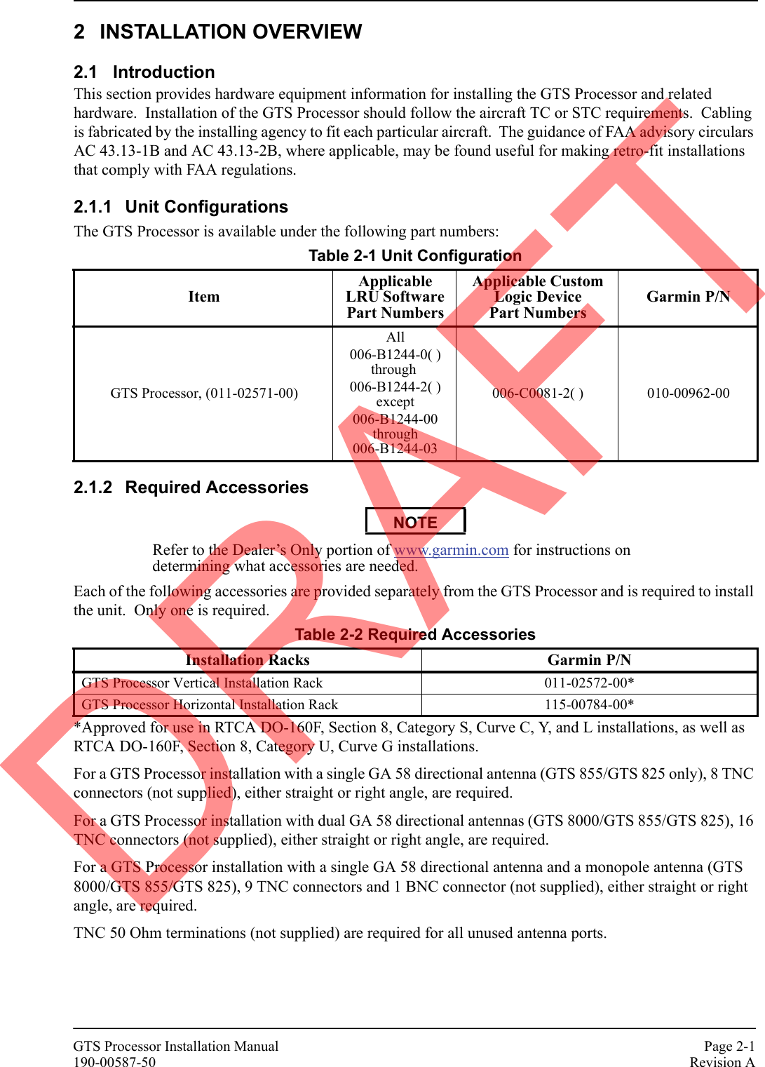
![GTS Processor Installation Manual Page A-3190-00587-50 Revision AAPPENDIX A Outline and Installation DrawingsFigure A-3 GTS Processor Horizontal Outline Drawing1.99 50.53.48 88.3HEIGHTWITHOUT FEET4.10104.1HEIGHTWITH FEET12.80 325.1CENTER OF GRAVITYTBDOF GRAVITYTBDCENTEROF GRAVITYTBDCENTERCENTER OF GRAVITYTBD1.59 40.3 9.73247.02.40 61.0 8.10205.7.4611.72.75 69.92.75 69.96.42163.1OF GRAVITYTBDCENTERCENTER OF GRAVITYTBD6X NOTE 3NOTES:DIMENSIONS: INCHES [mm]1.DIMENSIONS ARE SHOWN FOR REFERENCE ONLY.2.MOUNTING HOLE FOR #8 PANHEAD OR SOCKET HEAD3. CAP SCREW. RECOMMENDED LENGTH .750 INCHES MINIMUM.MOUNTING FEET MAY BE REMOVED WHEN DESIRED FOR INSTALLATION.4. SEE FIGURE A-?? FOR DETAILS OF REUSE OF SCREWS AND MOUNTING HOLES IN A FOOTLESS INSTALLATION.DRAFT](https://usermanual.wiki/Garmin/0104455/User-Guide-1616455-Page-71.png)