Garmin 01097 LOW POWER COMMUNICATIONS TRANSMITTER User Manual USERS MANUAL
Garmin International Inc LOW POWER COMMUNICATIONS TRANSMITTER USERS MANUAL
Garmin >
USERS MANUAL
Tracking System
P/N 012-01097-00 Receiver
P/N 012-01113-00 Transmitter
owner’s manual
DRAFT
Not for reproduction
Tracking System Owner's Manual F1 1 1/16/2007 1:51:36 PM
All rights reserved. Except as expressly provided herein, no part of this manual may be reproduced, copied, transmitted,
disseminated, downloaded or stored in any storage medium, for any purpose without the express prior written consent of Garmin.
Garmin hereby grants permission to download a single copy of this manual onto a hard drive or other electronic storage medium
to be viewed and to print one copy of this manual or of any revision hereto, provided that such electronic or printed copy of this
manual must contain the complete text of this copyright notice and provided further that any unauthorized commercial distribution
of this manual or any revision hereto is strictly prohibited.
Information in this document is subject to change without notice. Garmin reserves the right to change or improve its products and
to make changes in the content without obligation to notify any person or organization of such changes or improvements. Visit the
Garmin Web site (www.garmin.com) for current updates and supplemental information concerning the use and operation of this
and other Garmin products.
Garmin
®
, AutoLocate
®
, TracBack
®
, BlueChart
®
, and MapSource
®
are registered trademarks of Garmin Ltd. or its subsidiaries and
may not be used without the express permission of Garmin.
This product includes technology owned by SiRF Technology, Inc. SiRF’s technology is protected by U.S. and foreign
patents pending and issued. SiRF, SiRFstar and the SiRF logo are registered trademarks of SiRF Technology, Inc.
SiRFstarIII and SiRF Powered are trademarks of SiRF Technology, Inc.
miroSD
™
is a trademark of The SD Card Association. TransFlash
™
is a trademark of the SanDisk Corporation
January 2007 Part Number 190-00714-00 Draft Rev B Printed in Taiwan
© 2007 Garmin Ltd. or its subsidiaries
Garmin International, Inc.
1200 East 151
st
Street,
Olathe, Kansas 66062, U.S.A.
Tel. 913/397.8200 or 800/800.1020
Fax 913/397.8282
Garmin (Europe) Ltd.
Unit 5, The Quadrangle, Abbey Park
Industrial Estate, Romsey, SO51 9DL,
U.K.
Tel. 44/0870.8501241
Fax 44/0870.8501251
Garmin Corporation
No. 68, Jangshu 2
nd
Road, Shijr, Taipei
County, Taiwan
Tel. 886/2.2642.9199
Fax 886/2.2642.9099
Tracking System Owner's Manual F2 2 1/16/2007 1:51:36 PM

Tracking System Owner’s Manual - Draft i
IntroductIon >
IntroductIon
Thank you for choosing the Garmin® 010-001097-
00 Receiver/010-01113-00 Transmitter Tracking
System. This system uses the proven performance of
Garmin GPS and full-featured mapping to create an
unsurpassed portable GPS receiver. When the receiver
is in communication with the transmitter it becomes a
highly accurate tracking device, capable of monitoring
up to ten transmitters at a time.
Compare the contents of this package with the
packing list on the box. If any pieces are missing,
contact your Garmin dealer immediately.
To get the most out of your new navigation/tracker
system, take time to read this manual and learn the
operating procedures for your unit in detail. This
manual is organized into the following sections.
The Introduction contains manual conventions, the
Table of Contents, the software license agreement,
product registration, and product care information.
The Getting Started section provides an overview of
the unit, how to turn the unit on, and acquire satellites.
The Basic Operation section provides information
about setting up waypoints, routes, and tracks.
The Main Pages section contains an overview of
the Satellite, Trip Computer, Map, Compass and
Altimeter Pages.
The Main Menu section describes features found on
the Main Menu and information about settings.
The Appendix contains information such as
specications, optional accessories, and maintenance
information. You can also nd warranty and FCC
information in the Appendix.
An Index is provided at the end of the manual.
Manual Conventions
This manual uses the term Warning to indicate a
potentially hazardous situation, which, if not avoided,
could result in death or serious injury.
This manual uses the term Caution to indicate a
potentially hazardous situation, which, if not avoided,
may result in minor injury or property damage. It may
also be used without the symbol to alert you to avoid
unsafe practices.
Tracking System Owner's Manual F1 1 1/16/2007 1:51:37 PM

ii Tracking System Owner’s Manual - Draft
IntroductIon >
Table of Contents
Introduction ....................................................... i
Manual Conventions ................................................ i
Software License Agreement ............................v
Product Registration ..........................................v
Contact Garmin ........................................................v
Caring for the Tracking System .....................viii
Cleaning the Cases .............................................. viii
Cleaning the Screen ............................................. viii
Storage ................................................................. viii
Water Immersion .................................................viii
Warning ..............................................................ix
Caution ................................................................x
Getting Started ................................................. 1
Receiver Overview .............................................1
Installing the Batteries .............................................2
Using the Keypad ...............................................3
Charging the Transmitter battery .............................4
Transmitter Overview .........................................4
Turning on the Receiver.....................................5
Adjusting the Backlight ...........................................5
Initializing the GPS Receiver .............................6
Using the Receiver .............................................7
Understanding Terms ...............................................7
Selecting Options and Entering Data .......................8
Using the Status Bar ................................................8
On-Screen Messages ................................................9
Using the Mapping Databases .................................9
Transferring Data to a microSD Card ....................10
Overview of the Main Pages ............................ 11
The Home Page .....................................................11
The Map Page ........................................................12
The Tracker Page ...................................................13
GPS Operation ............................................... 14
Creating and Using Waypoints .......................14
Marking Your Current Location ............................14
Creating Waypoints Using the Map .......................14
Creating a Waypoint Using Coordinates ...............14
Editing Waypoints..................................................14
Deleting Waypoints................................................14
Averaging the Waypoint’s Location.......................14
Projecting a Waypoint ............................................15
Proximity Waypoints .............................................15
Using the Find Menu .............................................15
Recent Finds ..........................................................16
Using the Find Item Information Page ..................16
Find Information Page Options Menu ...................16
Finding a Waypoint ................................................16
Finding a Geocache ...............................................16
Tracking System Owner's Manual F2 2 1/16/2007 1:51:37 PM

Tracking System Owner’s Manual - Draft iii
IntroductIon >
Finding a City ........................................................16
Finding an Interstate Exit ......................................16
Finding an Address ................................................17
Finding an Intersection ..........................................17
Searching for a Point of Interest ............................17
Custom Points of Interest ......................................17
Using Tracks .....................................................17
Track Proles .........................................................18
Navigating a Saved Track ......................................18
Creating a Route ....................................................18
Navigating a Route ................................................19
Editing a Route ......................................................19
Using the Route Page Options ...............................20
Main Pages ..................................................... 20
Satellite Page ....................................................20
Using the Satellite Page Options Menu .................21
Using Additional Map Data ...................................22
Changing the Zoom Range ....................................22
Map Orientation .....................................................23
Map Page Options .................................................23
Guidance Text ........................................................23
Measuring Distance ...............................................25
Restoring Defaults .................................................26
Compass Page ..................................................26
Using the Electronic Compass ...............................26
Compass Page Options ..........................................27
Sight ‘N Go Navigation .........................................28
Using the Course Pointer or Bearing Pointer ........28
Data Fields .............................................................28
Altimeter Page ..................................................28
Altimeter Page Options .........................................29
Plot Over Time or Distance ...................................29
View Pressure or Elevation Plots ..........................29
Zoom Ranges .........................................................30
View Points ............................................................30
View Points on Map ..............................................30
Calibrating the Altimeter .......................................30
Changing the Data Fields ......................................30
Trip Computer Page .........................................31
Trip Computer Page Options Menu .......................31
Main Menu ...................................................... 32
Tracks ................................................................32
Track Page Options ................................................32
Highway Page ...................................................33
Setup Menu Page .............................................33
System Setup .........................................................33
Display Setup .........................................................34
Interface Setup .......................................................34
Tones Setup ............................................................35
Page Sequence Setup .............................................35
Tracking System Owner's Manual F3 3 1/16/2007 1:51:37 PM

iv Tracking System Owner’s Manual - Draft
IntroductIon >
Map Page Setup ....................................................35
Routing Setup ........................................................35
Geocache Setup .....................................................36
Marine Setup ..........................................................36
Time Setup .............................................................37
Units Setup ............................................................37
Heading Setup ........................................................38
Calibration Setup ...................................................38
Altimeter Setup ......................................................38
Welcome Setup ......................................................38
Jumpmaster ............................................................39
Proximity Waypoints ........................................41
Calendar ............................................................41
Calculator ..........................................................41
Stopwatch .........................................................41
Sun and Moon ...................................................41
Hunt and Fish ...................................................42
Games Menu .....................................................42
Appendix ........................................................ 42
Radio Receiver Specications ........................42
Interfacing .........................................................44
Data Field Denitions .......................................45
Optional Accessories .......................................47
Connecting Your Receiver to a Computer .....48
What Is WAAS/EGNOS? ...................................49
Map Datums and Location Formats ...............50
What Are Map Datums? ........................................50
What Is a Location Format? ..................................50
FCC Compliance ...............................................51
Limited Warranty ..............................................52
Index ............................................................... 54
Tracking System Owner's Manual F4 4 1/16/2007 1:51:37 PM

Tracking System Owner’s Manual - Draft v
IntroductIon >
Software License Agreement
BY USING THE 010-01097-00/010-01113-00 TRACKING
SYSTEM, YOU AGREE TO BE BOUND BY THE TERMS
AND CONDITIONS OF THE FOLLOWING SOFTWARE
LICENSE AGREEMENT. PLEASE READ THIS
AGREEMENT CAREFULLY.
Garmin grants you a limited license to use the software
embedded in this device (the “Software”) in binary
executable form in the normal operation of the product.
Title, ownership rights, and intellectual property rights
in and to the Software remain in Garmin.
You acknowledge that the Software is the property of
Garmin and is protected under the United States of
America copyright laws and international copyright
treaties. You further acknowledge that the structure,
organization, and code of the Software are valuable trade
secrets of Garmin and that the Software in source code
form remains a valuable trade secret of Garmin. You agree
not to decompile, disassemble, modify, reverse assemble,
reverse engineer, or reduce to human readable form the
Software or any part thereof or create any derivative
works based on the Software. You agree not to export or
re-export the Software to any country in violation of the
export control laws of the United States
of America.
Product Registration
Help us better support you by completing our online
registration today! Have the serial number of your
Receiver handy and connect to our Web site (http://
www.garmin.com). Look for the Product Registration
link on our Home page.
Use this area to record the serial number in case your
Receiver is lost, stolen, or needs service. Be sure
to keep your original sales receipt in a safe place or
attach a photocopy inside the manual.
Serial Number: ___ ___ ___ ___ ___ ___ ___ ___
Contact Garmin
If you encounter any difculty while using
your Receiver, or if you have any questions, in the
U.S.A. contact Garmin Product Support by phone:
913/397.8200 or 800/800.1020, Monday–Friday, 8
AM–5 PM Central Time; or go to www.garmin.com
and select Technical Support.
In Europe, contact Garmin (Europe) Ltd. at
44/0870.8501241.
Tracking System Owner's Manual F5 5 1/16/2007 1:51:37 PM

vi Tracking System Owner’s Manual - Draft
IntroductIon >
IMPORTANT: READ THIS INFORMATION BEFORE
USING YOUR 010-01097-00/010-01113-00 System:
Exposure to Radio Frequency Signals—Your wireless handheld
tracking system is a low power radio transmitter and receiver.
When it is on, it receives and also sends out radio frequency
(RF) signals. In August 1996, The Federal Communications
Commissions (FCC) adopted RF exposure guidelines with
safety levels for handheld wireless radios. Those guidelines are
consistent with safety standards previously set by both U.S. and
international standards bodies: American National Standards
Institute (ANSI) IEEE. C95.1-1992; National Council on
Radiation Protection and Measurements (NCRP) Report 86;
International Commission on Non-Ionizing Radiation Protection
(ICNIRP) 1996. Those standards were based on comprehensive
and periodic evaluations of the relevant scientic literature. For
example, over 130 scientists, engineers, and physicians from
universities, government health agencies, and industry reviewed
the available body of research to develop the ANSI Standard
(C95.1). The design of your radio complies with the FCC
guidelines (and those standards).
For body-worn and face-held operation, this radio
demonstrates compliance and meets the FCC RF exposure
guidelines for uncontrolled exposure (general population)
when used with approved accessories supplied with or
designed for this product. Use of other accessories may not
ensure compliance with FCC RF exposure guidelines.
Antenna Care—Use only the supplied antenna. Unauthorized
antennas, modications, or attachments could damage the
radio and may violate FCC regulations. Do not use any radio
that has a damaged antenna, because if it comes into
contact with your skin, a minor burn can result.
Electronic Devices—Most modern electronic equipment is
shielded from RF signals. However, certain equipment may
not be shielded against the RF signals from your wireless
radio.
Pacemakers—The Health Industry Manufacturers Association
(HIMA) recommends that a minimum separation of six inches
(6”) be maintained between a handheld wireless radio and a
pacemaker to avoid potential interference with the pacemaker.
These recommendations are consistent with the independent
research by and recommendations of Wireless Technology
Research. Persons with pacemakers should ALWAYS keep
the radio more than six inches from their pacemaker when
the radio is turned on, should not carry the radio in a breast
pocket, should use the ear opposite the pacemaker to minimize
the potential for interference, and should turn the radio off
immediately if you have any reason to suspect that interference
is taking place.
Hearing Aids—Some digital wireless radios may interfere
with some hearing aids. In the event of such interference, you
may want to consult your hearing aid manufacturer to discuss
alternatives.
Tracking System Owner's Manual F6 6 1/16/2007 1:51:37 PM

Tracking System Owner’s Manual - Draft vii
IntroductIon >
Other Medical Devices—If you use any other personal
medical device, consult the manufacturer of your device to
determine if it is adequately shielded from external RF energy.
Your physician may be able to assist you in obtaining this
information.
Turn your radio OFF in health care facilities when any
regulations posted in these areas instruct you to do so.
Hospitals or health care facilities may be using equipment that
could be sensitive to external RF energy.
Vehicles—RF signals may affect improperly installed or
inadequately shielded electronic systems in motor vehicles.
Check with the manufacturer or its representative regarding
your vehicle. You should also consult the manufacturer of any
equipment that has been added to your vehicle.
Posted Facilities—Turn your radio OFF in any facility where
posted notices so require.
Commercial Aircraft—Many commercial airlines prohibit
the use of radios on board. Switch OFF your radio before
boarding an aircraft or check the airline rules.
Blasting Areas—To avoid interfering with blasting operations,
turn your radio OFF when in a “blasting area” or in areas
posted: “Turn off two-way radio.” Obey all signs and
instructions.
Potentially Explosive Atmospheres—Turn your radio OFF
and do not remove your battery when you are in any area
with a potentially explosive atmosphere. Obey all signs and
instructions. Sparks from your battery in such areas could
cause an explosion or re resulting in bodily injury or even
death.
Areas with a potentially explosive atmosphere are often, but
not always clearly marked. They include fueling areas such
as gasoline stations, below deck on boats, fuel or chemical
transfer or storage facilities; vehicles using liqueed petroleum
gas (such as propane or butane); areas where the air contains
chemicals or particles, such as grain, dust, or metal powders;
and any other area where you would normally be advised to
turn off your vehicle engine.
Tracking System Owner's Manual F7 7 1/16/2007 1:51:37 PM

viii Tracking System Owner’s Manual - Draft
IntroductIon >
Caring for the Tracking System
The cases are constructed of high-quality materials
and does not require user maintenance except
cleaning.
Cleaning the Cases
Clean both unit’s outer casing (except for the
receiver’s screen) using a cloth dampened with a mild
detergent solution and then wipe dry. Avoid chemical
cleaners and solvents that may damage plastic
components.
Cleaning the Screen
Clean the Receiver’s screen using a soft, clean, lint-
free cloth. Use water, isopropyl alcohol, or eyeglass
cleaner if needed. If these are used, apply the liquid
to the cloth, and then gently wipe the screen with the
moistened cloth.
Storage
Do not store the Tracking System where prolonged
exposure to temperature extremes may occur (such as
in the trunk of a car) as permanent damage may result.
User information, such as waypoints and routes, are
retained in the unit’s memory without the need for
external power. It is always a good practice to back
up important user data by manually recording it or
downloading it to a PC (transferring it to MapSource
software).
Water Immersion
The Tracking System is waterproof to IEC Standard
60529 IPX7. It can withstand immersion in 1 meter
of water for 30 minutes. Prolonged submersion can
cause damage to the unit. After submersion, be certain
to wipe and air dry the unit before reuse or charging.
Tracking System Owner's Manual F8 8 1/16/2007 1:51:38 PM
Tracking System Owner’s Manual - Draft ix
IntroductIon >
Warning
Failure to avoid the following potentially hazardous situations
could result in an accident or collision resulting in death or
serious injury.
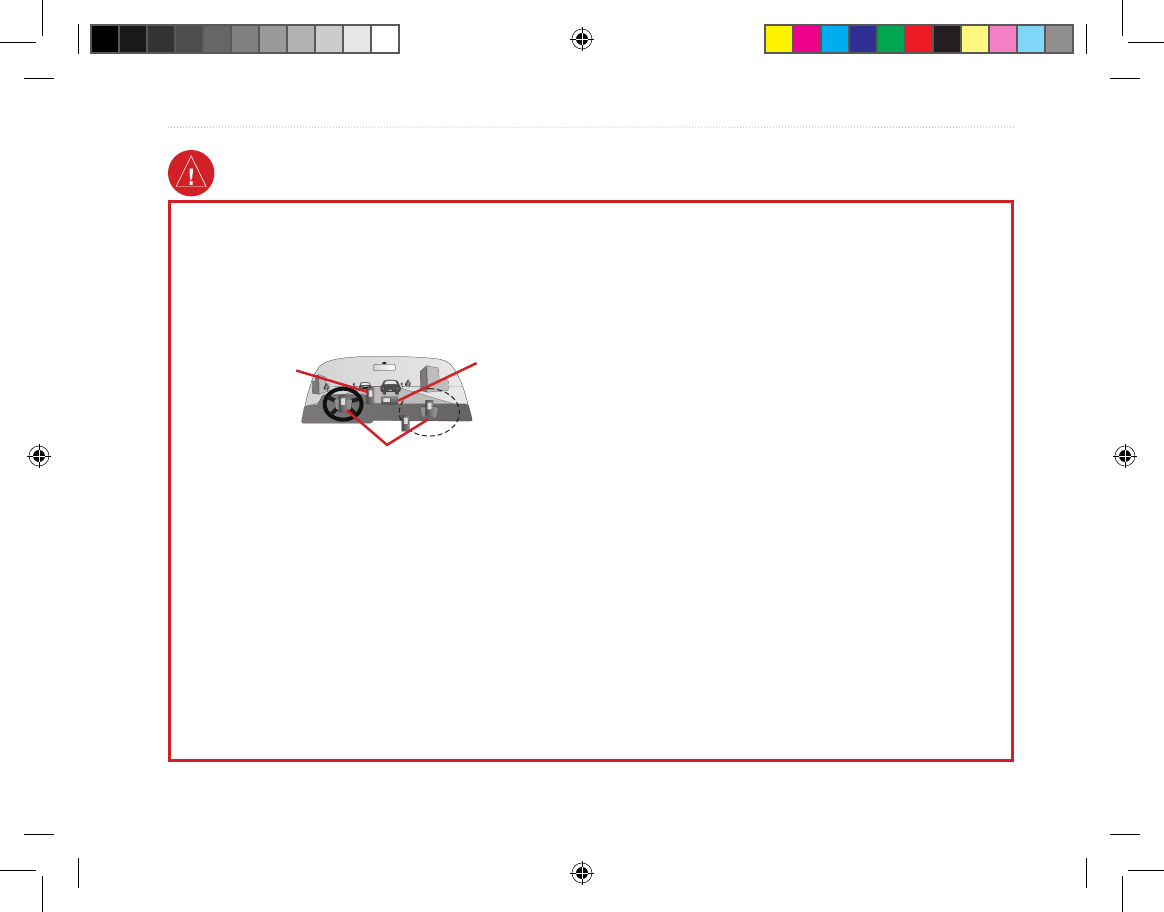
When installing the Receiver in a vehicle, place the unit securely
so that it does not interfere with vehicle operating controls or
obstruct the driver’s view of the road (see diagram).
Always operate the vehicle in a safe manner. Do not become
distracted by the Receiver while driving, and always be fully
aware of all driving conditions. Minimize the amount of time
spent viewing the screen of the Receiver while driving and use
voice prompts when possible. Do not enter destinations, change
settings, or access any functions requiring prolonged use of
the unit’s controls while driving. Pull over in a safe and legal
manner before attempting such operations.
When navigating, carefully compare information shown on
the Receiver to all available navigation sources, including
information
from street signs, visual sightings, and maps.
For safety, always resolve any discrepancies or questions
before continuing navigation. The Transmitter contains a
replaceable, rechargeable lithium-ion battery. The battery
may present a risk of re or chemical burn if mistreated.
• Do not disassemble, heat above 140°F (60°C), or
incinerate.
• Keep used battery away from children.
• Only replace with Garmin Lithium-ion Battery
Pack (Garmin Part Number 010-10XXX-00). No
other lithium-ion battery is compatible with the
unit.
• Dispose of used battery or unit properly. Contact
your local waste disposal department for
information on properly disposing of lithium-ion
batteries.
Use the electronic chart in the Receiver only to facilitate,
not to replace, the use of authorized government charts.
Ofcial government charts and notices to mariners contain all
information needed to navigate safely.
When navigating in an aircraft, use the Receiver only as an
aid for VFR navigation. Use terrain and obstacle data only
as an aid to situational awareness.
Do not mount
where driver’s
eld of vision is
blocked.
Do not place
unsecured on
the vehicle
dash.
Do not mount in front of an airbag
eld of deployment.
Tracking System Owner's Manual F9 9 1/16/2007 1:51:38 PM
x Tracking System Owner’s Manual - Draft
IntroductIon >
Failure to avoid the following potentially hazardous
situations may result in injury or property damage.
Use the GPS functionality of the Receiver only as a
navigational aid. Do not attempt to use the Receiver for
any purpose requiring precise measurement of direction,
distance, location, or topography. This product should
not be used to determine ground proximity for aircraft
navigation.
The Global Positioning System (GPS) is operated by the
United States government, which is solely responsible for
its accuracy and maintenance. The government’s system
is subject to changes which could affect the accuracy and
performance of all GPS equipment, including the Receiver.
Although the Receiver is a precision navigation device, any
navigation device can be misused or misinterpreted and,
therefore, become unsafe.
Map Data Information: One of the goals of Garmin is to provide customers with the most complete and accurate cartography
that is available to us at a reasonable cost. We use a combination of governmental and private data sources, which we identify in
product literature and copyright messages displayed to the consumer. Virtually all data sources contain inaccurate or incomplete
data to some extent. This is particularly true outside the United States, where complete and accurate digital data is either not
available or prohibitively expensive.
Caution
NOTICE TO DRIVERS IN CALIFORNIA AND MINNESOTA: State law prohibits drivers in California and Minnesota from
using suction mounts on their windshields while operating motor vehicles. Other Garmin dashboard or friction mounting options
should be used. Garmin does not take any responsibility for any nes, penalties, or damages that may be incurred as a result of
disregarding this notice. (See California Vehicle Code Section 26708(a); Minnesota Statutes 2005, Section 169.71.)
The California Electronic Waste Recycling Act of 2003 requires recycling. Refer to www.erecycle.org.
WARNING: This product, its packaging, and its components contain chemicals known to the State of California to cause cancer,
birth defects, or reproductive harm. This Notice is being provided in accordance with California’s Proposition 65. If you have any
questions or would like additional information, please refer to our Web site at http://www.garmin.com/prop65.
Tracking System Owner's Manual F10 10 1/16/2007 1:51:38 PM
Tracking System Owner’s Manual - Draft 1
GettInG Started >
GettInG Started
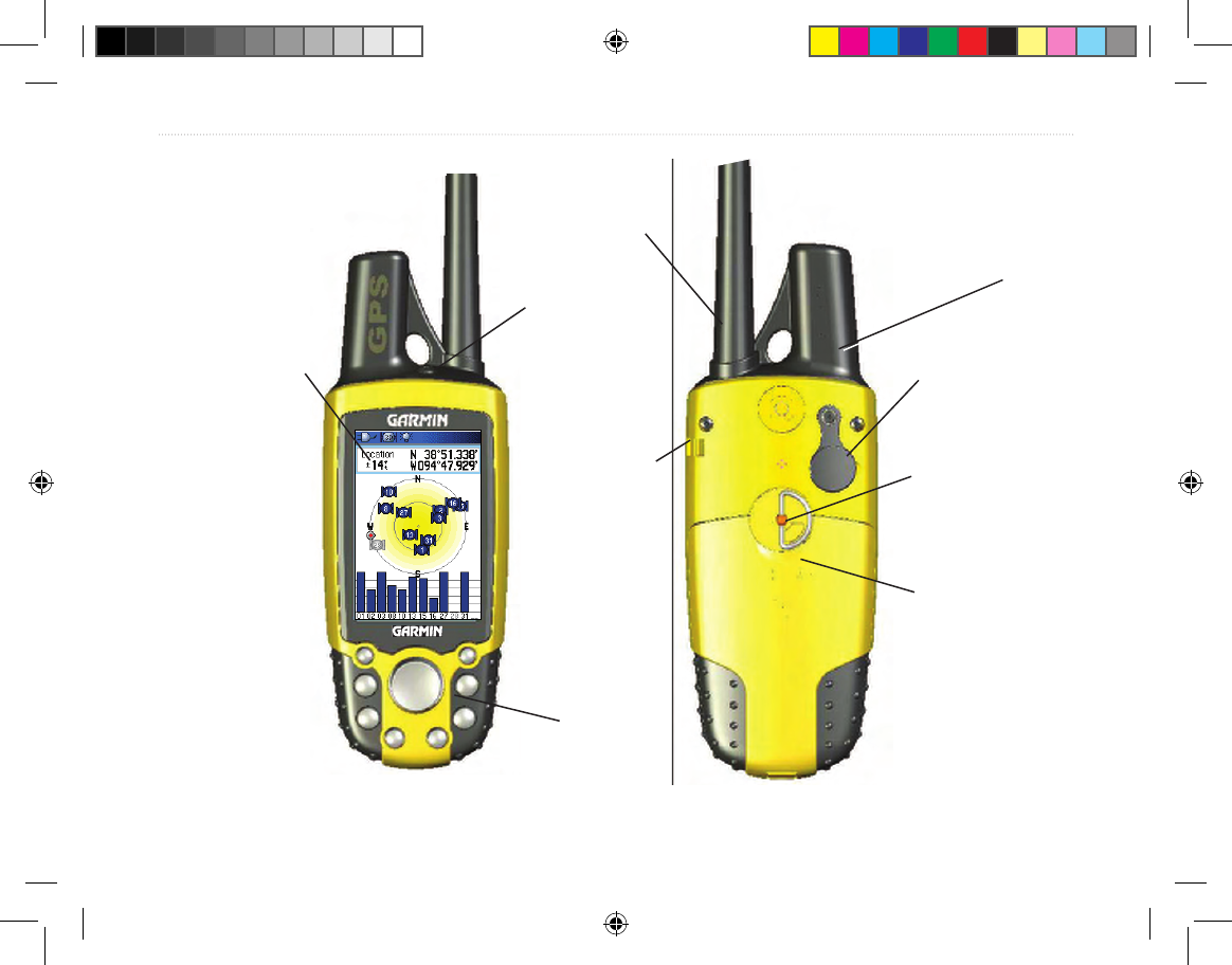
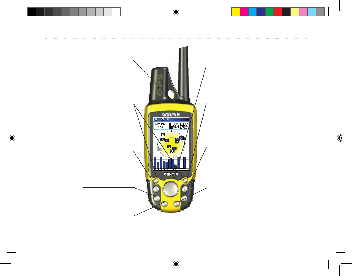
Receiver Overview
Carry lanyard
attachment slot
Battery
compartment cover
USB External Data/
Auxilary Power Port
(under weather cap)
Internal
GPS
antenna
Battery
compartment
locking D-Ring
Radio Receiver
Antenna
Keypad
LCD
display
screen
Power key
Tracking System Owner's Manual F1 1 1/16/2007 1:51:39 PM
2 Tracking System Owner’s Manual - Draft
GettInG Started >
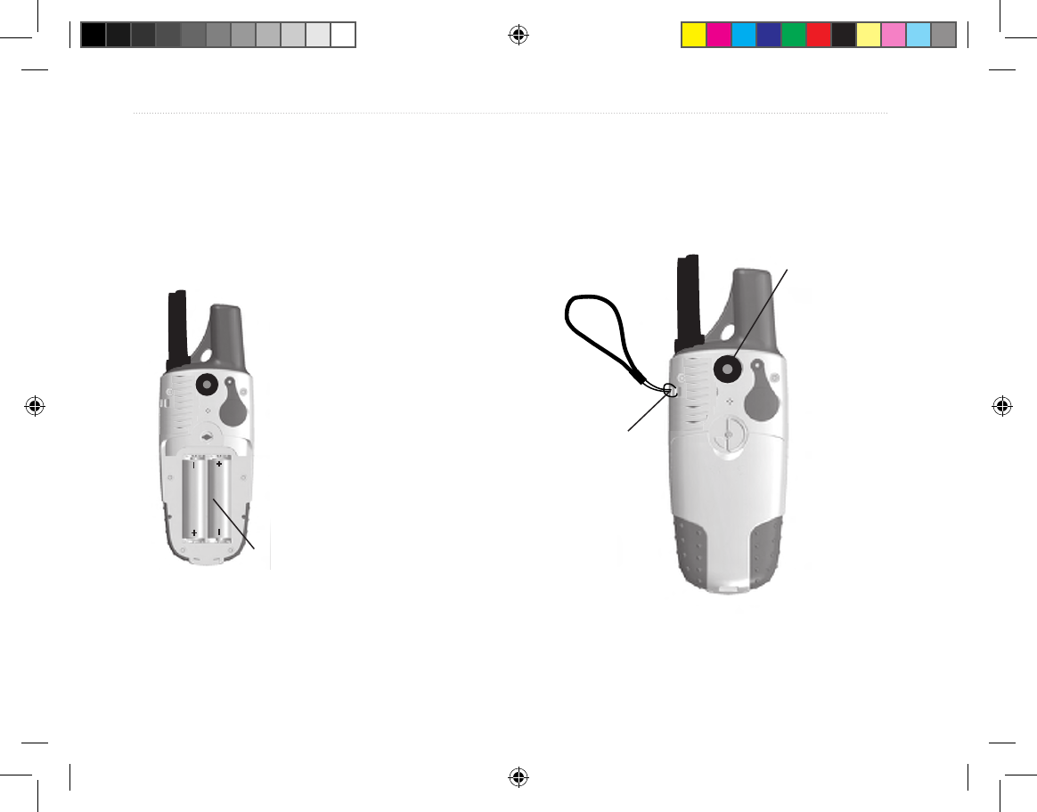
Installing the Batteries
The Receiver operates on two AA batteries (not
included), which are located in the back of the unit.
You can use Alkaline or NiMH batteries. See page 67
for information on setting the battery type.
To install the batteries:
1. Remove the battery cover
by turning the D-Ring 1/4
turn counter-clockwise and
pulling the cover loose.
2. Insert the batteries,
observing the proper
polarity. A polarity diagram
is molded into the battery
compartment.
3. Reinstall the battery cover
by aligning the back cover
with the unit and turning the
D-Ring 1/4 turn clockwise.
Remove the batteries from the Receiver when you do
not expect to use the unit for several months. Stored
data is not lost when batteries are removed.
To install the Lanyard:
1. Place the loop of the Lanyard through the slot
at the at the upper left side on the back of the
unit.
2 Route the strap through the loop and pull tight.
Refer to page 9 for information on accessing the
microSD data card in the battery compartment.
USE BY 2009
USE BY 2009
Battery
Compartment
Wrist Strap
Installation
Belt Clip Button
attaches here.
(Be certain to fully
engage threads and
tighten snug)
Tracking System Owner's Manual F2 2 1/16/2007 1:51:41 PM
Tracking System Owner’s Manual - Draft 3
GettInG Started >
Using the Keypad
BACK Key
• Press and release to cancel data entry or exit a page.
ENTER Key
• Press and release to enter highlighted
options, data or conrm on-screen
messages.
IN/OUT Zoom Keys
• Press to zoom in or out on the
Map Page.
• Press to scroll up or down a
list on any other page.
Track Key
• Press and release at any time
to view the Tracker Page.
POWER Key
• Press and hold to turn the unit
on or off.
• Press and release to adjust the
backlighting.
ROCKER Key
• Press up, down, left, or right to
highlight options and to enter data, or
move the map panning arrow.
MAP Key
• Press and release to go directly to the
Map Page.
• Press and hold to turn the compass
on or off
MENU Key
• Press and release to view page
options.
• Press twice to view the Main Menu.
MARK Key
• Press and release at any time
to mark your current location.
Tracking System Owner's Manual F3 3 1/16/2007 1:51:41 PM
4 Tracking System Owner’s Manual - Draft
GettInG Started >
Charging the Transmitter battery
The Transmitter operates on a rechargeable Lithium-
ion battery, which is located in the unit. The battery
can be charged using either the AC or DC charging
accessory. The battery has been partially charged at
the factory, but should be fully charged before use.
To charge the battery:
1. Insert the small plug on the charger into the
charging port on the Transmitter.
2. Connect the power plug on the charger to a 12
VDC cigarette lighter if using the DC charger
or a 115-120 VAC wall outlet id using a the AC
charger.
3. Observe the ashing LED on the Transmitter
indicating that charging is in process. When
fully charged the LED remains steady A
fully charged Transmitter should provide
approximately 10 hours of operation..
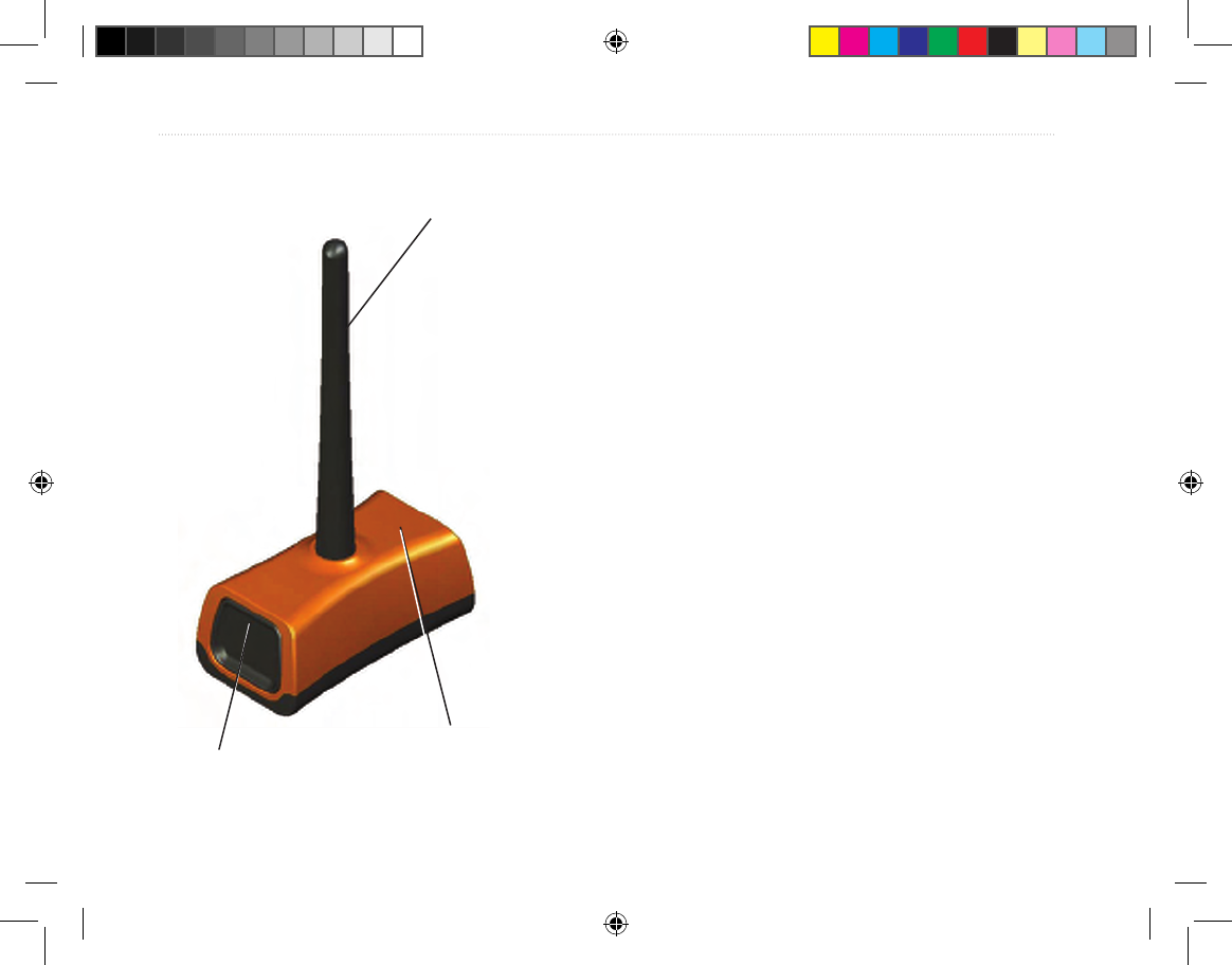
Internal
GPS
antenna
Radio Transmitter Antenna
Power key
Transmitter Overview
Tracking System Owner's Manual F4 4 1/16/2007 1:51:41 PM
Tracking System Owner’s Manual - Draft 5
GettInG Started >
Turning on the Receiver
When the Receiver is turned on, the Introduction Page
appears, followed by the Satellite Page. The unit must
collect satellite data and establish its current location.
To turn the Receiver on and off:
1. Press and hold the POWER key. When
the unit turns on, a tone sounds and the
Introduction Page appears, followed by the
Satellite Page.
2. To turn off the unit, press and hold the POWER
key again.
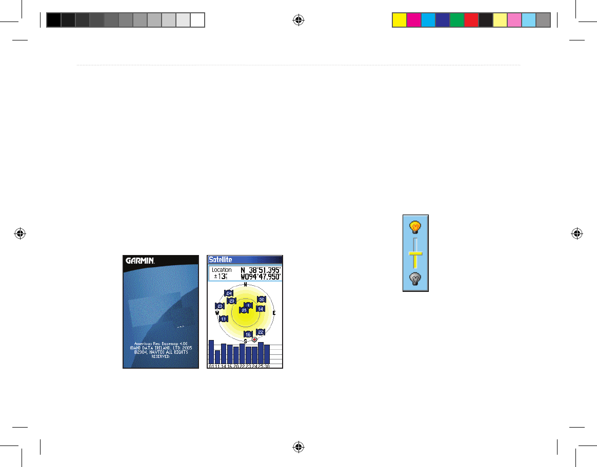
Adjusting the Backlight
You may want to adjust the backlight to see the
display better.
To adjust the backlight level:
1. Press and quickly release the POWER key.
2. Press up on the ROCKER to increase the
brightness, or press down to decrease.
3. Press ENTER or QUIT to close the Backlight
adjustment window.
Backlight Adjustment Slider
Welcome Page Satellite Page
Tracking System Owner's Manual F5 5 1/16/2007 1:51:41 PM
6 Tracking System Owner’s Manual - Draft
GettInG Started >
Initializing the GPS Receiver
The rst time you turn on your Receiver, the GPS
receiver must collect satellite data and establish its
current location. To ensure proper initialization,
the GPS receiver is shipped from the factory in
AutoLocate mode, which allows the receiver to “nd
itself” anywhere on Earth. To receive satellite signals,
you must be outdoors and have a clear view of the
sky.
To initialize your Receiver:
1. Press and hold the POWER key to turn on the
Receiver.
2. Hold the unit in front of you with the top tilted
upward. While the GPS receiver is searching
for the satellite signals, a “Locating Satellites”
message is replaced by an “Acquiring
Satellites” message until enough signals are
acquired to x its location.
When the receiver has signals from at least
three satellites, the display at the top of the
page changes to indicate position accuracy
and location coordinates.
3. Press and release the PAGE key until the Map
Page appears. You are now ready to begin
GPS aided navigation.
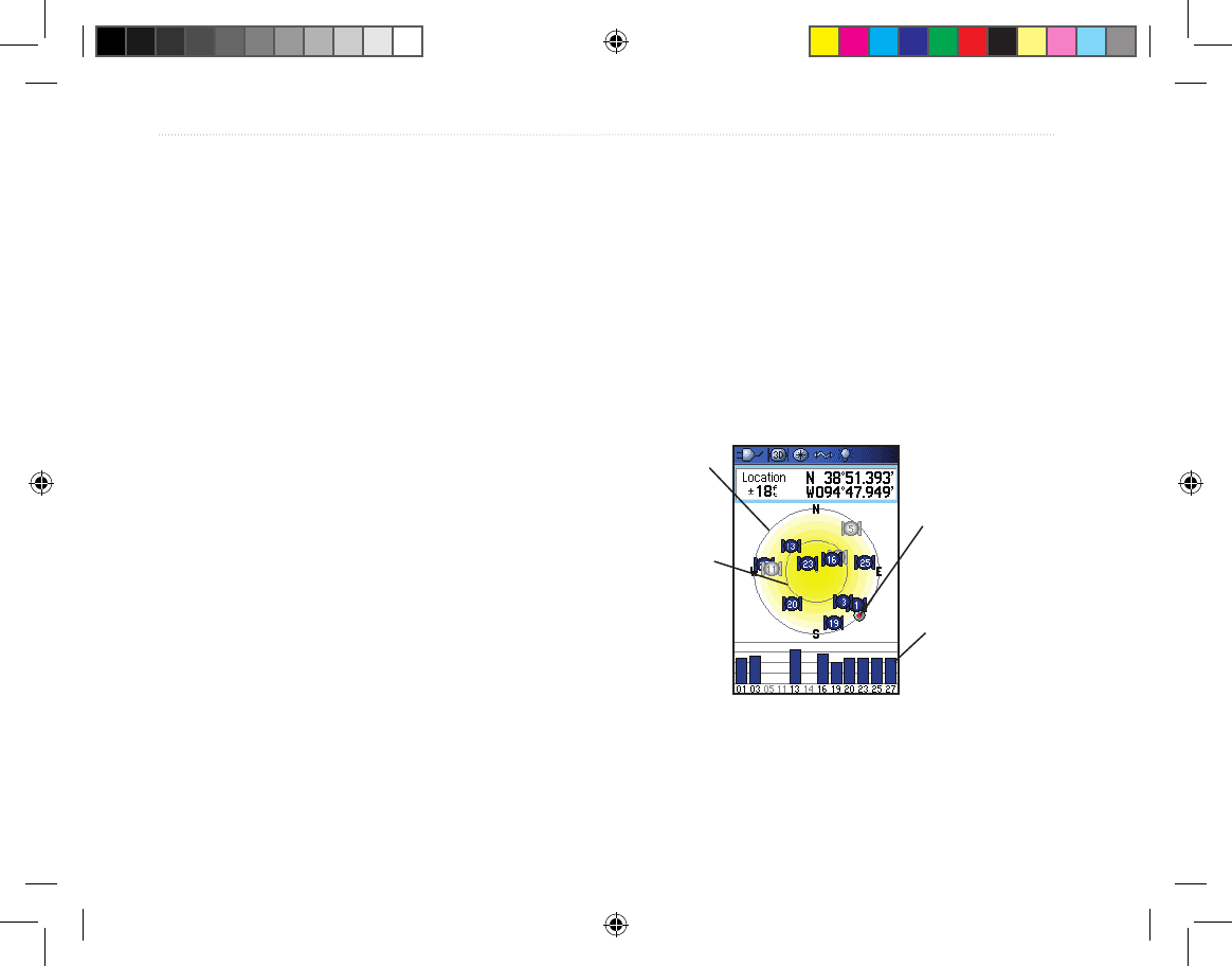
You can also observe a sky view array of the satellites
overhead with your location centered in the array. The
outer circle represents the horizon and the inner circle
a position 45 degrees from the horizon. The numbers
shown indicate the number assigned to each satellite.
A bar graph at the bottom of the page shows the
strength of signals from each satellite.
Strength of
each satellite
signal
The outer
circle
represents
the horizon.
The inner
circle is a
location 45
degrees from
the horizon.
Heading bug
indicates your
direction of
movement
If the unit cannot get a satellite x, a list of solutions
appears. Select an appropriate solution and press
ENTER to continue.
Tracking System Owner's Manual F6 6 1/16/2007 1:51:42 PM
Tracking System Owner’s Manual - Draft 7
GettInG Started >
Using the Receiver
This section explains how to enter and select
information with the Receiver.
Understanding Terms
As you progress through this owner’s manual, you are
directed to press a specic key or highlight a eld on
the screen. When you are directed to press a key, you
should press and quickly release the key. A key may
need to be held down for a period of time to start a
secondary function, when the instructions tell you to,
do so. When a eld is highlighted on the screen, it is
highlighted in yellow. The position of the highlight is
controlled by the ROCKER.
The following terms are used throughout this manual:
Highlight—move the highlighted area on the screen
up, down, left, or right with the ROCKER to select
individual elds.
Field—the location on a page where data or an
option can be shown and entered. Select (highlight)
a eld using the ROCKER to begin entering data or
selecting options.
On-screen button—use the ROCKER to highlight a
button, and press ENTER to select the button.
Scroll bar—when viewing a list of items too long to
appear on the screen, a scroll bar appears along the
right side of the list. To scroll through a list, press up
or down on the ROCKER or use Zoom In to scroll a
set of items and Zoom Out to scroll the entire screen.
Default—the factory setting saved in the unit’s
memory. You can change the settings, but you can
also revert to the factory (default) settings when you
select Restore Defaults when offered as an option.
Highlighted
eld
On-screen buttons
Field
Tracking System Owner's Manual F7 7 1/16/2007 1:51:42 PM
8 Tracking System Owner’s Manual - Draft
GettInG Started >
Selecting Options and Entering Data
To enter data and select options, use the ROCKER to
highlight, select, or choose an item in a list or a eld
on the screen.
To select and activate an option:
1. From any page, press MENU. An Options
Menu appears with a list of additional options
for that page.
2. Use the ROCKER to move the highlight up,
down, right, or left on the menu to highlight the
option you want, and press ENTER to select it.
To exit a menu or return to the previous
setting:
Press QUIT. The QUIT key moves backward
through your steps. Press QUIT repeatedly to
return to the starting page.
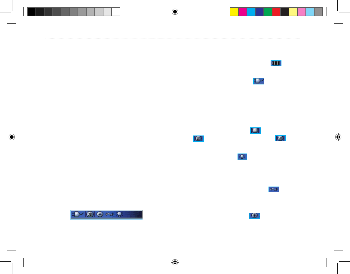
Using the Status Bar
At the top of each page, the status bar provides status
information for several unit features.
Status Bar
• Power to the unit is provided by either batteries
or from an auxiliary source (AC, DC or USB
Adapter). The Battery Power icon ( ) shows
the remaining power as the battery is depleted.
• The Auxiliary Power icon ( ) appears when
the unit is powered by an external source such
as the USB Data Cable provided with the unit
or optional Serial Port Data/Power Cable or
Cigarette Lighter Adapter.
• Satellite signal status is shown when searching
for or acquiring satellites ( ), when a 2D x
() is attained and when a 3D x ( ) is
attained (four or more satellites are received.)
• The Backlight icon ( ) appears when the
backlight is on. Backlighting is off when
you turn the unit on. The Backlight uses a
signicant amount of battery power.
• The USB Cable Connection icon ( )
appears when the unit is in communication with
a PC Universal Serial Bus.
• Electronic compass icon ( ) appears when
the electronic compass is turned on.
Tracking System Owner's Manual F8 8 1/16/2007 1:51:42 PM
Tracking System Owner’s Manual - Draft 9
GettInG Started >
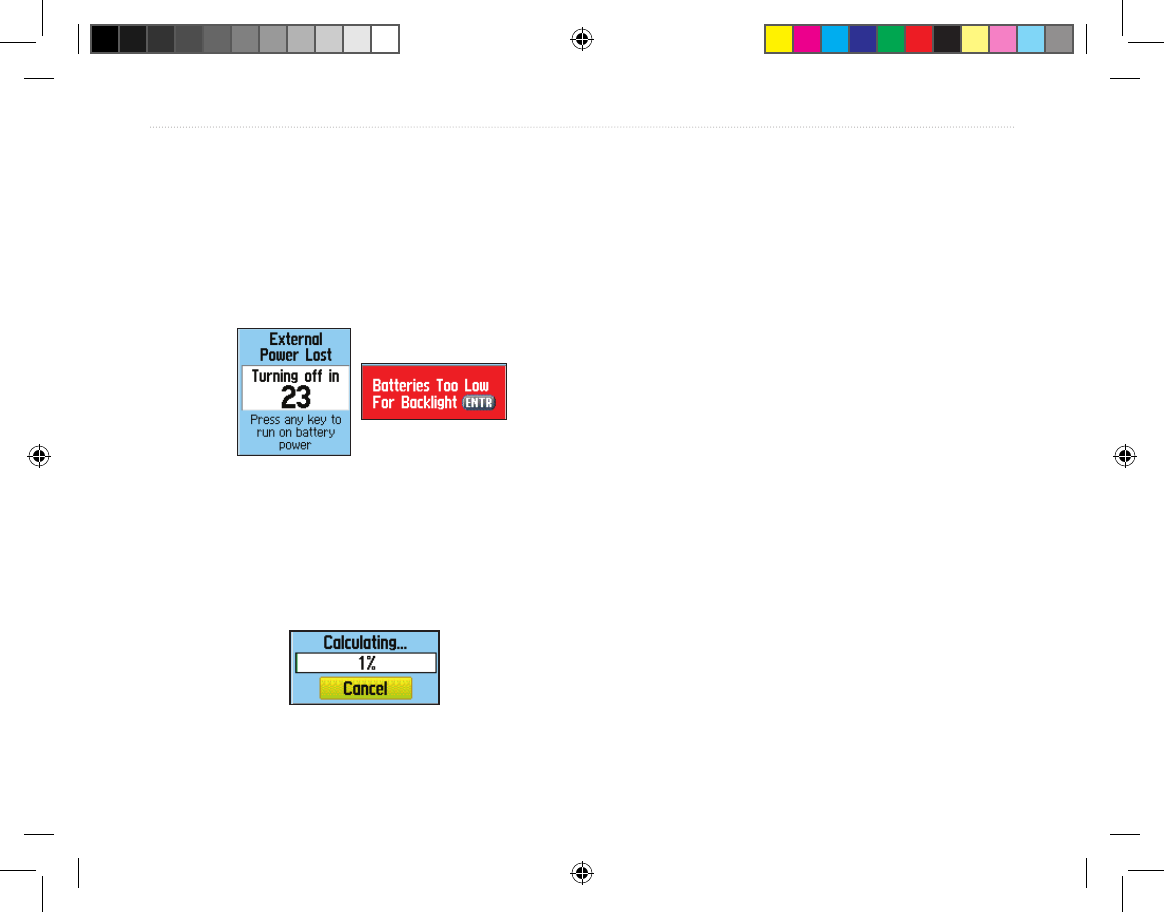
On-Screen Messages
When a signicant event in the operation of the unit
occurs, an on-screen message appears to advise you of
the occurrence. In each case the condition is described
and often a remedy provided. Press ENTER to
acknowledge the message and close the window.
On-Screen Messages
In some instances the message may indicate a
temporary condition such as the “Calculating
Route” message and close as soon as calculation is
completed.
Using the Mapping Databases
Many of the Receiver features require detailed
mapping data in order to be fully operational, so you
may want to transfer maps before using the unit. The
microSD card (provided with some units) can be
loaded with detailed maps from optional MapSource
disks for your PC to enhance the versatility of your
unit. With selected MapSource detailed mapping data,
you can view listings of nearby restaurants, lodging,
shopping centers, attractions and entertainment, and
even retrieve addresses and phone numbers for any
listed location. The amount of data transferable is
limited to the capacity printed on the microSD card.
Map data transfer requires the USB Interface Cable
provided with the unit to transfer MapSource data
from a PC to the microSD card in the Receiver. To
transfer data to the microSD card you can also use the
USB Mass Storage feature on page 69.
You can purchase high capacity microSD cards
at your local electronics supplier. See the Garmin
Web site (http://www.garmin.com/cartography/) for
compatible MapSource products.
Calculating Route
Message
Tracking System Owner's Manual F9 9 1/16/2007 1:51:42 PM
10 Tracking System Owner’s Manual - Draft
GettInG Started >
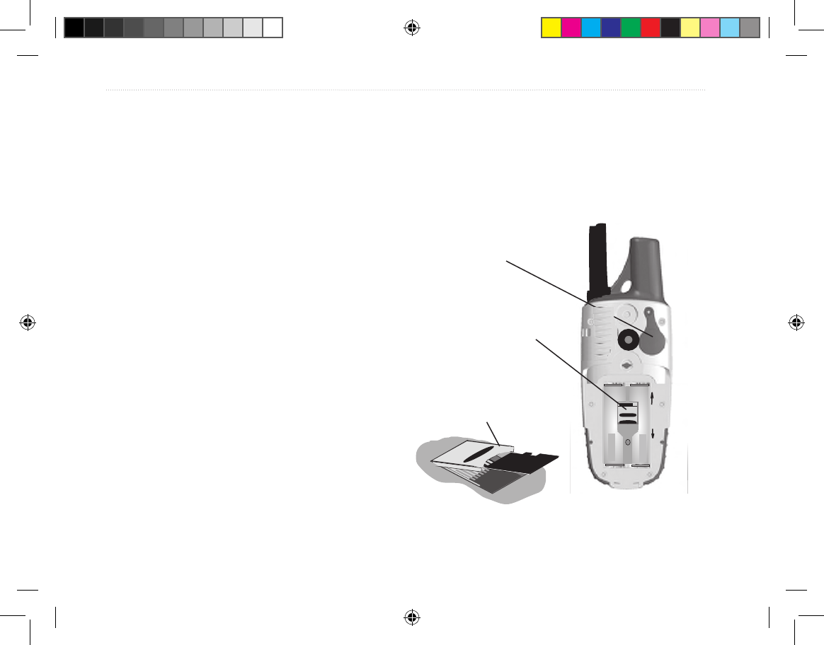
Transferring Data to a microSD Card
Some units are equipped with a pre-installed microSD
card.
To install or remove the microSD card:
1. Remove the Battery Compartment Cover
from the back of the unit and remove the two
batteries.
2. Locate the card tray at the center of the
battery tray and check to be certain the card is
installed in the tray.
3. If you desire to remove the card, slide the tray
cover up, then lift it toward you to remove the
card from the tray.
4. To re-insert the card, lay the card in the tray,
close the tray, and replace the batteries and
cover when nished.
To transfer map data to the microSD card:
1. Lift the weather cover from the USB port on
the upper back of the unit. It recommended
that you use the USB port rather than the
Serial Connection port for faster data transfer.
2. Connect the USB cable provided with the unit
to the USB port on your PC and to the mini-
USB port on the back of the unit.
3. Follow instructions for selecting and
downloading maps provided with the
MapSource map data disk.
USB Port
- under weather
cover
Back of Receiver with
Battery Cover removed
Slide the tray cover back to
OPEN, then lift to remove
or insert the microSD card.
Close and slide forward to
LOCK.
Detail of microSD card tray
in Battery Compartment
microSD card tray
is located beneath
the batteries in the
battery compartment.
Unlock
Lock
Tracking System Owner's Manual F10 10 1/16/2007 1:51:43 PM
Tracking System Owner’s Manual - Draft 11
BaSIc operatIon >
Overview of the Main Pages
The Receiver has three main pages: the Home Page
(Main Menu), the Map Page and the Tracker Page.
You can cycle through these pages by pressing the
Back key. An Active Route Page appears only when
you are navigating a route.
Each page (except the Home Page) has an options
menu, which contains the page setup options and
features that apply to that page. To view the options
menu for a page, press the Menu key, then use the
Rocker key to scroll the list and press Enter to select
the desired option.
The Home Page
The Home Page or Main Menu is the directory to
accessing the unit features. The Main Menu lists the
pages for:
• The Find Feature
• The Accessories Menu
• The Setup Menu
• The Navigation Utilities Page
• The Hunt & Fish Page
• The Sun & Moon Page
• The Satellite Page
• The Transmitter List
The Find Menu
The Find Menu is a list of categories for item
locations. The list contains items marked and recorded
by the user such as waypoints and geocaches,
Transmitter locations which are updated each time
the transmitter communicates with the Receiver, and
cities, interstate exits, and points of interest contained
in the map database or in downloaded Garmin
MapSource detailed mapping data.
The Accessories Menu
This page lists the operating system features that
accent the main functional software of the unit.
These consist of items such as a calender, calculator,
stopwatch, etc.
Tracking System Owner's Manual F11 11 1/16/2007 1:51:43 PM

12 Tracking System Owner’s Manual - Draft
BaSIc operatIon >
The Setup Menu
This Setup Menu provides a method for customizing
the Tracking System to meet your personal needs.
You can setup the System, Display, Alert Tones, the
page sequence, the Map Page, Routes, Time, Units of
Measure, etc.
The Navigation Utilities Page
This page allows to access utilities used to enhance
navigation capabilities. They include; Trip Computer,
Compass, Altimeter, Tracks, Routes, Highway,
Proximity Alarms, Turn Previews, and Active Routes.
The Hunt & Fish Page
The Hunt & Fish page is an almanac of the best times
for hunting or shing for any given location.
The Sun & Moon Page
The Sun & Moon page provides a graphic
representation of sun and moon positions for any
time., annual date, and location on Earth. It also
shows sunrise, sunset, moonrise and moonset times
for a selected time, date, and location.
The Satellite Page
The Satellite page shows the GPS receiver status,
satellite locations, satellite signal strength and
receiver’s current location.
The Transmitter List
The Transmitter List keeps track of all transmitters
being monitored by the Receiver. Data pages for each
transmitter can be accessed from this list.
The Map Page
The Map Page is the main navigation page. This
page consists of a map dening the area around your
current location. The map displays your current
location as a triangular arrow point and the location
of transmitters as a named or numbered point with
a dotted track line to indicate its path of travel. The
Map Page also indicates direction of travel and moves
the map with you as you travel.
Tracking System Owner's Manual F12 12 1/16/2007 1:51:43 PM

Tracking System Owner’s Manual - Draft 13
BaSIc operatIon >
The Tracker Page
The Tracker Page provides distance and direction
information for each transmitter being tracked. Up
to three transmitters can be displayed on the Tracker
page at one time with a compass indicating the
direction of each and a scrollable list indicating the
distance from the receiver.
The rst time you use the Receiver and Transmitter
together you must setup the Tracker Page. The
Tracking System uses a low-power, 2.4 GHz,
wireless link for short range (approx. 20 feet)
two-way communication to set Transmitter identity
conguration. It uses radio one-way communication
allowing the Transmitter to report GPS position data
to the Receiver. You can track up to ten different
transmitters using one Receiver.
Touching the Receiver to the Transmitter ensures a
clear path of wireless communication and allows the
Receiver to communicate with the Transmitter.
Once recognized by the Receiver, the Transmitter is
placed on the Transmitter List where it can be viewed
on an Info page where it can be renamed and data
about its current state, distance, distance traveled,
and average speed can be viewed. Update rates
for position reporting can be set, battery capacity,
communication and GPS signal strength can also be
viewed.
Each additional transmitter added to the Transmitter
list must be synched to the receiver and given a
specic identity to avoid conicts in position and data
reporting.
Tracking System Owner's Manual F13 13 1/16/2007 1:51:43 PM

14 Tracking System Owner’s Manual - Draft
BaSIc operatIon >
GPS oPeratIon
This section explains some of the more common
operations you can perform with your Receiver
including creating and using waypoints, using the
Find Menu, and how to create and use tracks and
routes.
Creating and Using Waypoints
Waypoints are locations or landmarks you record and
store in your GPS. They are locations you might want
to return to later. You can add waypoints to routes and
even create a Go To directly to the selected waypoint.
Waypoints can be created using three methods. You
can press the MARK key while at a location, create a
waypoint on the Map Page, or enter coordinates for a
waypoint manually.
Marking Your Current Location
Use the MARK key to quickly capture your current
location to create a new waypoint. You must have a
valid position (2D or 3D) x to mark your current
location.
Creating Waypoints Using the Map
You can quickly create a waypoint using the Map
Page. When you pan the map and move the arrow
over a map item, you see a highlighted description of
the item.
Creating a Waypoint Using Coordinates
You can manually enter location coordinates to create
a waypoint. This method is useful for creating a
waypoint at a specic latitude/longitude position from
a chart.
Editing Waypoints
You can edit waypoints when created or at a later
date. You can change the symbol, name, note,
location, elevation, and depth.
Deleting Waypoints
You can delete waypoints from the Waypoint Page.
Averaging the Waypoint’s Location
You can average a new waypoint location over time to
produce a more accurate location.
Tracking System Owner's Manual F14 14 1/16/2007 1:51:43 PM
Tracking System Owner’s Manual - Draft 15
BaSIc operatIon >
NOTE: You must have a GPS Satellite x before
you can average a waypoint’s location. You
cannot average a waypoint after it has been
saved to the waypoints list and Mark Waypoint
page closed.
Projecting a Waypoint
You can create a new waypoint by projecting the
distance and bearing from a specic location to a new
location.
Proximity Waypoints
Use the Proximity Waypoints Page to dene an alarm
circle around a stored waypoint location.
Use Proximity Waypoints to dene the
boundaries of a hunting area.
Prior to hunting a parcel of land, mark the a perimeter
boundary with proximity waypoints on the Map Page.
Set the alarm to sound when you near the boundary
to prevent encroachment onto to posted land. Use
the Map Page panning arrow to scroll to the general
area you plan to hunt, then zoom in to view the area
in detail. Place the panning arrow on a boundary and
press ENTER to mark it as a waypoint. Continue
placing boundary markers (waypoints) until you have
dened a perimeter. Use the Set Proximity option
from each waypoint to activate the boundary alarm.
Using the Find Menu
Use the Find Menu to search for waypoints, cities,
and exits included in the Receiver basemap. You
can also nd saved waypoint and geocache points.
Additional icons appear depending on the optional
BlueChart or MapSource data loaded to the unit. Press
FIND to open the Find Menu.
When you access a Find group list, it contains only those
items near your current location or the pointer (if active).
The options menu for each category contains a
submenu of search options, such as Find By Name,
Find Nearest (near your current location), Select
Symbol (for waypoints), Change Reference (by moving
the pointer to a new location), Nearest Containing (a
keyword you enter), Select Category (for those groups,
such as Food & Drink and Lodging). Use these
options to shorten your
search.
Tracking System Owner's Manual F15 15 1/16/2007 1:51:44 PM

16 Tracking System Owner’s Manual - Draft
BaSIc operatIon >
Recent Finds
The Recent Finds Page shows a list of the last 50
items you have searched for or gone to recently.
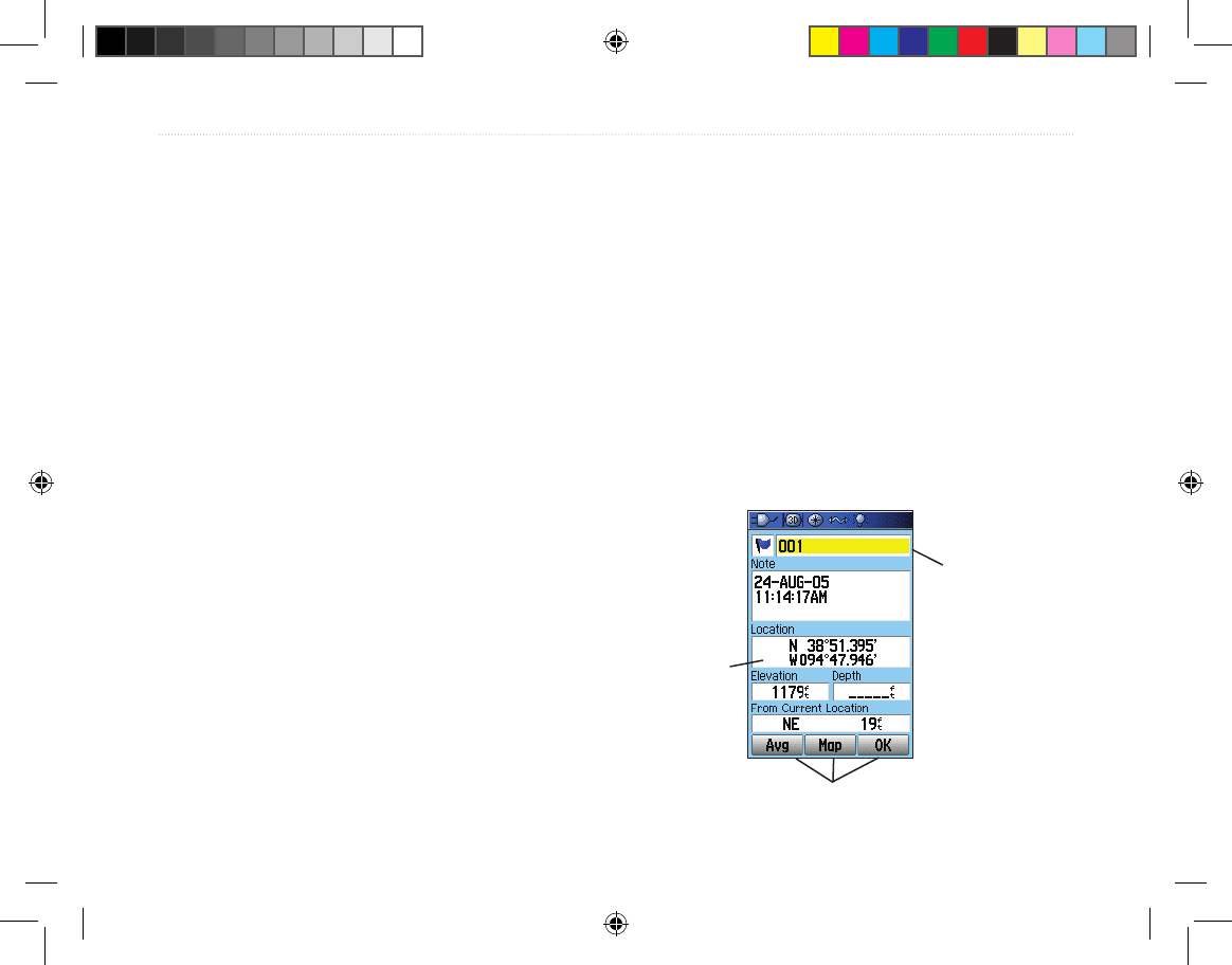
Using the Find Item Information Page
When you select an item from the Find item list and
press ENTER, an information page shows detailed
information about the item. Each information page
contains three on-screen buttons. Different buttons
appear depending on whether you are selecting a Find
item to navigate to or adding a Find item to a route list.
Find Information Page Options Menu
The Options Menu for each information page contains
options for using a Find item as a tool for navigation.
Finding a Waypoint
The Waypoints Page contains a list of all saved
waypoints. Waypoints are stored in alphanumeric
order and are also identied by a symbol assigned
from a list of symbol types.
Finding a Geocache
Use the Geocache icon to view the list of geocache
locations created using your Receiver or downloaded
from your computer. A geocache location is a
waypoint with a special geocache symbol assigned
to give special signicance and to allow it to be
separated from others on the waypoints list.
For more information about creating a geocache
point, see Geocache Setup instructions on page 72 and
www.garmin.com/products/gpsmap60csx/.
When a geocache is found, the unit marks the cache
as found, logs an entry into the calendar, and provide
an option that, when activated, shows the nearest
cache.
Finding a City
Use the Cities icon on the Find Menu to nd any city
listed in the mapping database (either in the basemap
or from downloaded detailed mapping data).
Finding an Interstate Exit
Use the Exits icon on the Find Menu to nd an
interstate exit.
Tracking System Owner's Manual F16 16 1/16/2007 1:51:44 PM

Tracking System Owner’s Manual - Draft 17
BaSIc operatIon >
Finding an Address
If you downloaded detailed mapping data, use the Addresses
icon on the Find Menu to nd an address. When you enter
the street number, street name, and city, the nd feature
matches that data with addresses in the map database.
Finding an Intersection
If you downloaded detailed mapping data, use the
Intersections icon on the Find Menu to search
for an intersection. When you enter the two street
names and a city, the Find feature matches them with
intersections in the map database.
Searching for a Point of Interest
If you downloaded MapSource detailed mapping,
you can use the All Points of Interest icon on the
Find Menu to locate a nearby restaurant, lodging,
landmark, public building, and so on.
If you are searching for a restaurant that is part of
a national chain, only the restaurant nearest to your
location is shown when you search using the Find
Nearest option. If you search using the By Name
option, all of the locations for that chain in the
mapping database are shown with the closest to your
current location listed rst.
Custom Points of Interest
You can create your own category for points of interest
by using the Garmin POI Loader utility available from
the Garmin Web site:
www.garmin.com/products/poiloader/. Follow the
instructions for use
on the Web site.
Using Tracks
The Tracks feature creates an electronic breadcrumb
trail or “track log” on the Map Page as you travel. The
track log contains information about points along its
path, including time, location, elevation, and depth for
each point (depth requires NMEA input, see page 92).
The track log starts recording as soon as the unit gets
a location x. The percentage of memory used by the
current track log appears at the top of the Tracks Page.
After you clear the track log, it shows 0%.
Use the Saved Track page to rename the track, view
the track distance and calculated area, and specify a
color for the track on the Map Page.
Tracking System Owner's Manual F17 17 1/16/2007 1:51:44 PM

18 Tracking System Owner’s Manual - Draft
BaSIc operatIon >
Track Proles
After you save a track, you have a record of the path
you traveled and a track altitude prole.
You can create a Track Elevation Prole
from Digital Elevation Models (DEM) maps
(MapSource U.S. Topo 24K), which include
elevation data contained in the map. When these
types of maps are available, a Use Map Data
- Use Track Data option menu appears when
you select Prole. Refer to the Garmin Web site,
www.garmin.com/cartography/ontheTrail/, for
more information about MapSource U.S. Topo
24K maps.
Navigating a Saved Track
You can save your track log to use later as a
TracBack. When initiated, a TracBack route takes you
back to the oldest stored track log point.
Creating and Using Routes
Route navigation allows you to create a sequence of
intermediate waypoints that lead you to your nal
destination. The Receiver lets you store 50 routes with
up to 250 points each.
Creating a Route
You can create or modify a route using the Routes
Page, and you can add waypoints to a route from
the Find Menu. You can create more complex routes
using a PC and MapSource mapping programs and
then transfer them to the unit memory. Auto-Routes,
which are generated when you select Go To for a
Find item, map item, or waypoint, cannot be saved.
Saved routes with more than 50 waypoints cannot be
navigated using the Follow Roads option.
Methods of navigating to a destination
• If you select the Go To button on the Waypoint
Page or other Find Menu items, the Receiver
creates a straight path (point to point) from
your current location to that location.
• If you select the Navigate button on a Route
Tracking System Owner's Manual F18 18 1/16/2007 1:51:44 PM

Tracking System Owner’s Manual - Draft 19
BaSIc operatIon >
Page, the Receiver creates a route composed
of several user waypoints or Find Menu items,
with the last being your destination. It navigates
directly from point to point. Before each turn
in the route, a turn page shows a guidance
message and graphic of the turn. You can view
the turns at any time by pressing up or down on
the ROCKER while the route is active.
• Both navigation methods change when you
select the Follow Roads option on the Routing
Setup Page. Both Go To navigation and point to
point routing become routes that allow you to
navigate using roads.
The routes use existing roadways (either those
in the basemap or from downloaded detailed
mapping) to automatically calculate a route to
your destination. Turns on roadways are added
to the Active Route Page and are preceded by a
guidance message with a graphic of the turn. If
there are not enough roads at your location to
calculate a route, a message appears.
Navigating a Route
After you create a route, you can begin navigation
immediately or save it to the Saved Routes list.
When navigating a route, a guidance message and
a graphic view of turns in the route appear as you
approach each one. Using the Follow Roads option
on the Routing Setup Page increases the number of
turns and shows an Active Route Page with a list of
turns. If you selected the Off Road option, you can
view only the list of points for a route from the Active
Route Page. See Routing Setup on page 71.
Editing a Route
After you create a route, use the Route Page to edit,
change the route name, and review route points.
Select Distance to enter a radius so that when you are
within the entered distance, the Receiver leads you to
the next point on your route.
Select Manual to transition to the next waypoint
anytime while navigating a route.
Tracking System Owner's Manual F19 19 1/16/2007 1:51:44 PM

20 Tracking System Owner’s Manual - Draft
MaIn paGeS >
Using the Route Page Options
The Route Page shows all points stored in memory for
the route selected on the Routes Page. Press MENU
to open the Route Page Options Menu.
• Remove All—removes all waypoints from the
saved route.
• Route—reverses the order of the route points in
the saved route.
•
Prole—creates a vertical prole of the route
when MapSource U.S. Topo 24k map data is used.
• Copy Route—makes a copy of the saved route
with the same name followed by a number.
• Delete Route—deletes the saved route.
• Change Data Fields—select different values
for the two data elds at the bottom of the page.
• Restore Defaults—restore route settings to the
factory default setting
MaIn PaGeS
The Tracking System has six main pages: Satellite
Page, Trip Computer Page, Map Page, Compass Page,
Altimeter Page, and the Main Menu. You can cycle
through these pages by pressing the PAGE key to
move forward or pressing the QUIT key to reverse.
Add more pages using the Page Sequence option on
the Main Menu. The Active Route Page appears only
when you are actively navigating.
Each page has an Options Menu, which contains the
setup options and functions that apply to the page. To
view the Options Menu for a page, press the MENU
key.
Satellite Page
The Satellite Page shows the receiver status, satellite
locations, satellite signal strength, and the receiver’s
current location when the unit receives signals from at
least three satellites.
Tracking System Owner's Manual F20 20 1/16/2007 1:51:44 PM
Tracking System Owner’s Manual - Draft 21
MaIn paGeS >
Using the Satellite Page Options Menu-
Press MENU to open the Options Menu.
Use With GPS Off/On —enables you to turn the GPS
receiver on or off.
Track Up/North Up—indicates whether satellites are
shown with the rings oriented with North toward the
top of the display or your current track toward the top
of the display
Multicolor/Single Color—indicates whether each
satellite is shown in a different color or the same
color.
New Location—use if you have moved the unit more
than 600 miles and you are having trouble locking
onto satellite signals.
GPS Elevation— your GPS determined elevation.
Map Page
The Receiver comes with a built-in basemap that
includes a database of cities, interstates, state and
county highways, exit information, and lake and river
outlines. The standard basemap can be enhanced
using MapSource or BlueChart data.
Two map operating modes, position mode and pan
mode, determine what cartography is shown on the
map display. Position mode pans the map to keep
your present location in the display area. The position
marker shows your travel on the Map Page. When
you press the ROCKER, the Receiver enters pan
mode, which moves the map to keep the white arrow
(map pointer) within the display area.
When you are in panning mode, you can move the
map pointer about the page to highlight and identify
map items. If there is more than one map item under
the pointer, a list appears with the item highlighted on
the map, also highlighted on the list.
Tracking System Owner's Manual F21 21 1/16/2007 1:51:44 PM

22 Tracking System Owner’s Manual - Draft
MaIn paGeS >
You can add and congure up to four optional data
elds to the top of the page to provide a variety of
travel and navigational information.
Using Additional Map Data
Optional MapSource mapping data disks enhance
the versatility of your Tracking System. With
MapSource data, you can view listings of nearby
restaurants, lodging, shopping centers, attractions,
and entertainment, and you can retrieve addresses and
phone numbers for any listed location. With additional
BlueChart data, you can access information, such as
marine navaids, wrecks, obstructions, and anchorage
locations.
You can view the data currently loaded on your unit
and microSD card.
Changing the Zoom Range
You can change the zoom range on the Map Page to
view a smaller area in greater detail or view a larger
area with less detail. Press IN to decrease the zoom
range and show an area with greater detail; press
OUT to increase the zoom range and show a larger
area with less detail.
The current zoom range setting is shown in the
lower-left corner of the Map Page. If no further map
information is available, “overzoom” appears under
the zoom range. When using MapSource maps,
“mapsource” appears below the scale.
Tracking System Owner's Manual F22 22 1/16/2007 1:51:44 PM

Tracking System Owner’s Manual - Draft 23
MaIn paGeS >
Map Orientation
There are two map orientation options: North Up
orients the map like a paper map. Track Up orients the
map in the direction of travel. When using Track Up,
the North arrow indicates the orientation. Set the map
orientation using the Setup Map option.
Map Page Options
Use the Map Page Options Menu to customize the
Map Page. With the Map Page open, press MENU. To
select an option, highlight it, and press ENTER.
The following options are available:
• Stop (Resume) Navigation—stops navigation
and is disabled when there is no active navigation.
• Recalculate—recalculates a route and is
disabled when there is no active navigation.
• Data Fields—opens the Show sub-menu so
you can select the number of data elds to show
at the top of the Map Page: Map Only, 2, 3, or 4
data elds.
• Change Data Fields—allows you to select the
type of data you want to show in the data elds.
This option is available only if the 2, 3, or 4
data elds option have been selected.
• Guidance Text—shows messages on the screen
advising you of your next navigation move
when navigating to a destination.
• Setup Map—accesses six pages of Map
display settings so you can customize the map
to your preferences.
• Measure Distance (Stop Measuring)—
measures the distance from your current
location to the map pointer.
• Turn Declutter On (Off)—eliminates the
display of items on the map that can block road
details when the map is zoomed out.
• Restore Defaults—returns the map display to
the factory set defaults.
Guidance Text
When navigating, guidance text appears above the
map. Guidance Text shows useful information when
navigating to a destination.
Tracking System Owner's Manual F23 23 1/16/2007 1:51:44 PM

24 Tracking System Owner’s Manual - Draft
MaIn paGeS >
If you select Always Show, a guidance message
always appears whether or not you are navigating.
If you select Show When Navigating, a guidance
message appears until you select Stop Navigation
from the Options Menu.
Setting up the Map Page
Use the Setup Map option to adjust how items are
shown on the Map Page.
Map Setup – General Page
The Map Setup – General Page contains the settings
for Orientation, Below, Auto Zoom, Detail, and Lock
On Road.
• Orientation—selects how the map is shown.
North Up always shows north at the top of
the page. Track Up shows your current track
toward the top of the page.
• Below—sets the map scale at which the Track
Up feature displays. All scales above that revert
to the North Up map orientation.
• Auto Zoom—zooms the map scale to include
the beginning and ending points of a route.
• Detail—selects the degree of map detail shown.
• Lock On Road—locks the current position
pointer to show on the nearest road,
compensating for variances in map position
accuracy.
Map Setup – Tracks Page
The Map Setup – Tracks Page contains settings for
Saved Tracks, Track Log, Track Points, and the Go To
Line.
• Saved Tracks—sets the maximum zoom range
at which saved tracks are shown on the map.
• Track Log—sets the maximum zoom range at
which active track logs are shown.
• Track Points—sets the maximum number of
track points used to record a track.
• Go To Line—selects either a bearing or course
line for navigating a track.
Tracking System Owner's Manual F24 24 1/16/2007 1:51:45 PM

Tracking System Owner’s Manual - Draft 25
MaIn paGeS >
Map Setup – Points Page
Us the Map Setup – Points Page to set the map scale
at which Map Points, User Waypoints, Street Label,
and Land Cover appear on the Map Page. Select
Auto, Off, or a specic zoom level.
Map Setup – Text Page
Use the Map Setup – Text Page to select the text size
for descriptions of map items on the Map Page. You
can select from None, Small, Medium, or Large.
Map Setup – Information Page
The Map Setup – Text Page shows a list of
downloaded detailed maps such as topographic,
marine charts, and MapSource maps with auto-routing
capability. Use the ROCKER to highlight a map, and
press ENTER to show it on the map display or turn
it off.
Press MENU to view the options for displaying maps.
Map Setup – Marine Page
Use the Map Setup – Marine Page to customize settings
for marine colors, spot soundings, light sectors, and
symbol sets when using downloaded marine charts
(MapSource BlueChart marine mapping data).
• Marine Colors—toggles marine colors on or
off on the Map Page.
• Spot Soundings—toggles spot soundings on
or off on the Map Page. (Depth measurements
shown on the map)
• Light Sectors—select Off, Auto, or ON.
(Navigational light locations)
• Symbol Set—select the symbol set to use
(Auto, GARMIN, NOAA, International).
Measuring Distance
You can measure the distance between two map items.
Turning Declutter On or O
You can remove
unwanted items from the Map Page display (declutter
the display) such as map item titles and icons. This
is useful when the map is zoomed to a scale that is
partially obscured by titles and icons that remain the
same size regardless of the map scale.
Tracking System Owner's Manual F25 25 1/16/2007 1:51:45 PM
26 Tracking System Owner’s Manual - Draft
MaIn paGeS >
Restoring Defaults
Use the Restore Defaults option to return the map
settings to factory settings.
Compass Page
During active navigation, the Compass Page guides
you to your destination with a graphic compass
display and a bearing or course pointer.
When navigating, the Compass Page provides
navigation data and directions. It uses a graphic
compass ring, a bearing or course pointer and digital
data elds to show information such as current speed,
distance to the next point on the route, and estimated
arrival time.
The rotating compass ring indicates the direction you
are heading. The Bearing and Course Pointer indicate
the direction (bearing) to your destination, relative to
your current heading direction. The compass ring and
bearing or course pointer work independently to show
your direction of movement and the direction to your
destination. You can choose the Bearing Pointer or
Course Pointer for guidance.
The compass ring is an electronic compass that
functions like a magnetic compass when you are
stationary. When you are moving and reach a pre-set
speed, it uses data from the GPS receiver to maintain
your heading. When you stop (after a pre-set time), it
again operates like a magnetic compass. The compass
ring is especially helpful when using a paper map or
chart with your Receiver for navigation. When the
electronic compass is on, a compass icon appears
in the status bar.
Using the Electronic Compass
When you turn the electronic compass off, it stays off
until you turn it on again. However, sometimes when
you turn the electronic compass on, the Receiver
overrides the compass and uses the GPS receiver to
track your heading. In fact, when you are moving at
a steady rate, the GPS receiver operates the compass.
When stationary, the electronic compass is active to
provide you accurate headings. You can customize the
criteria for switching between the electronic compass
and the GPS as explained in the Heading setup section
on page 75.
Tracking System Owner's Manual F26 26 1/16/2007 1:51:45 PM
Tracking System Owner’s Manual - Draft 27
MaIn paGeS >
To turn the electronic compass on or off:
1. Press and hold the PAGE key to turn the
electronic compass on or off. The Compass
Icon appears in the status bar when the
electronic compass is on. When you are not
using the electronic compass, turn it off to
conserve batteries. When it is turned off, the
unit uses the GPS receiver for navigation.
2. Hold the Receiver level to get an accurate
electronic compass reading. You can obtain
the most accurate reading if it is calibrated.
(See the following page for calibration
instructions.)
Calibrating the Electronic Compass
When you rst use the Receiver or after you install
new batteries, you have to calibrate the electronic
compass outdoors. The accuracy of the electronic
compass is adversely affected if the unit is not held
level or you are near objects that generate magnetic
elds, such as cars or buildings.
Compass Page Options
Use the options menu to customize the Compass
Page. With the Compass Page open, press MENU. To
select an option, highlight it, and press ENTER.
The following options are available:
•
Sight ‘N Go—allows you to navigate to an
object within your sight by pointing the unit at it.
• Stop or Resume Navigation—turns active
navigation for a route or a Go To on or off.
• Recalculate— recalculates the path to a
destination.
• Course or Bearing Pointer—toggles between
the course pointer and the bearing pointer.
• Data Fields—allows you to select the number
of data elds that appear on the Compass Page.
• Change Data Fields—allows you to select the
type of data you want to show in the data elds.
See page 93 for denitions of each option.
• Calibrate Compass—accesses the Compass
Calibration Page for calibrating the compass.
•
Restore Defaults—returns to the factory
settings.
Tracking System Owner's Manual F27 27 1/16/2007 1:51:45 PM

28 Tracking System Owner’s Manual - Draft
MaIn paGeS >
Sight ‘N Go Navigation
Sight ‘N Go allows you to set a course to a point you
can see in the distance.
Using the Course Pointer or Bearing
Pointer
The bearing pointer and course pointer work
independently of each other. The bearing pointer
indicates the direction to your destination, and the
course pointer indicates your relationship to a course
line leading to the destination.
If the bearing pointer arrow is pointing straight up, for
example, you are going directly to your destination.
If it points any direction other than up, turn toward
that direction until the arrow is pointing up and then
continue in that direction. The bearing pointer always
points to the destination, regardless of the direction you
are moving. Most efcient if you must move around
obstacles (lakes, private property, etc.) in your path.
If you are using the course pointer option, and you
drift away from the line of travel from your original
location to your destination, the course deviation
indicator (an arrow with horizontal dotted line)
provides graphic indication of drift (right or left)
according to the scale shown at the edge of the
compass ring.
Move to the right or left to get back on course. This is
most efcient if you are navigating on water or where
there are no major obstacles in your path. It also helps
you avoid hazards to either side of the course, such as
shoals or submerged rocks.
Data Fields
You can show 3 or 4 data elds on the Compass Page.
Altimeter Page
The Altimeter Page shows you the current elevation,
rate of ascent or descent, a prole of elevation
changes over distance or time, or a prole of pressure
changes over time.
The Status eld at the bottom of the page shows the
current elevation and your current rate of ascent or
descent when moving. It can also show the ambient
pressure and time of measurement.
Tracking System Owner's Manual F28 28 1/16/2007 1:51:45 PM

Tracking System Owner’s Manual - Draft 29
MaIn paGeS >
You can congure the Prole eld in the center of the
page to show either elevation or ambient pressure plots
as selected from the Altimeter Page Options Menu.
Data elds at the top of the page are user selectable
and show a variety of recorded or current data.
Altimeter Page Options
Use the Altimeter Page Options Menu to customize
the Altimeter Page. With the Altimeter Page open,
press MENU to open the Options Menu.
The following options are available:
• Plot Over Time or Plot Over Distance—plots
the elevation over a period of time or plots the
elevation over a distance.
• View Elevation Plot (View Pressure Plot)—
shows the elevation or the pressure plot.
• Zoom Ranges—allows you to the Zoom
Ranges for elevation, distance, or time when
you show the View Elevation Plot over distance
or time.
• Reset—allows you to reset the elevation data
and the maximum elevation data.
• Calibrate Altimeter—If you know the correct
elevation for your location, you can increase the
accuracy of the altimeter using the “Calibrate
Altimeter” option.
• Restore Defaults—clears recorded data from
the page and begins recording new data.
You can customize the “View” option displays
using the ”Zoom Ranges” option to determine time,
distance, pressure, and elevation parameters.
Plot Over Time or Distance
These two measurement options (changes over a set
period of time or changes over a set distance) apply
only to the View Elevation Plot option. The View
Pressure Plot option is measured by time and pressure
only. When one option is active, the other is shown on
the Altimeter Page Options menu.
View Pressure or Elevation Plots
Select the View Elevation Plot option to plot a prole
of elevation changes that occur as you navigate over
a set distance or period of time. Select View Pressure
Tracking System Owner's Manual F29 29 1/16/2007 1:51:45 PM

30 Tracking System Owner’s Manual - Draft
MaIn paGeS >
Plot to view a record of changes in barometric
pressure for a set period of time. When one option
is active, the other option is shown on the Options
Menu.
Zoom Ranges
You can set the zoom ranges for elevation, distance,
or time when you show the View Elevation Plot.
• Ranges for vertical distance are shown as you
press up or down on the ROCKER.
• Ranges for linear distance are shown as you
press left or right on the ROCKER.
• Ranges for time are shown for a time plot when
you press left or right on the ROCKER.
Ranges for View Pressure Plot pressure values are
shown when you press up or down on the ROCKER.
Values for time are shown in the same manner as for
elevation plots.
View Points
You can scroll through a recorded elevation or
pressure prole to view data for any point along the
prole. When the red vertical and horizontal cross
hairs are stopped at a location along the prole, the
screen shows the elevation or pressure, time of day,
and date when the point was recorded.
View Points on Map
You can view the location of points on the Map Page.
Resetting Data
You can reset the elevation data and the maximum
elevation data by selecting these options from the
Reset Page.
Calibrating the Altimeter
Because the Receiver relies on the barometric
pressure to determine the elevation and the pressure
at any given elevation can uctuate, you can calibrate
the altimeter to increase its accuracy. You must know
the elevation or pressure at your current location.
Changing the Data Fields
The Altimeter Page has two data elds that you can
customize. (For denitions, see page 84.)
Tracking System Owner's Manual F30 30 1/16/2007 1:51:45 PM

Tracking System Owner’s Manual - Draft 31
MaIn paGeS >
Trip Computer Page
The Trip Computer Page provides you with a
wide variety of travel data that can be useful when
navigating a long distance. It indicates your current
speed, average speed, trip odometer, and many other
helpful statistics useful for navigation.
You can customize the trip computer screen to meet
your personal requirements. Selecting the type of
data to display is done in the same manner as for the
similar data elds on the Map Page. (See page 40 for
details.) This page can be added to the Main Page
sequence using the Page Sequence Setup.
Trip Computer Page Options Menu
The following options are available:
• Reset—because you want to record new data
for each trip, a Reset option is available.
Reset the trip information by highlighting Reset
and pressing ENTER.
The Reset Page offers options for resetting
trip computer data, clearing the track log and
deleting saved tracks, waypoints and routes. This
page allows you select individual items, select
all and unselect all. When you make selections,
highlight the Apply button and press ENTER.
Answer OK to the “The Data You Have Selected
Will Be Permanently Deleted” prompt and press
ENTER to complete the reset.
• Big Numbers—allows you to view signicant
trip data at a glance by showing fewer data
elds with larger numbers.
• Change Data Fields—allows you to select the
type of data you want to show in the data elds.
• Restore Defaults—allows you to return the
data elds to factory settings.
Tracking System Owner's Manual F31 31 1/16/2007 1:51:45 PM
32 Tracking System Owner’s Manual - Draft
MaIn Menu >
MaIn Menu
The Main Menu contains settings and features not
found on the main pages and sub-menus. The time
and date are shown at the bottom of this page. The
Main Menu is accessible from any page by pressing
MENU twice. To select an item on the Main Menu,
highlight the menu item, and press ENTER.
NOTE: If a page from the menu is added to the
Main Page sequence, the icon does not appear
on the Main Menu. (See page sequence setup).
Tracks
The Tracks Page shows the percentage of track
memory used and a list of saved tracks. Use the
Tracks Page to set up, clear, or save a track log, or
enable the TracBack feature for the current track log.
For more information, see page 31.
Track Page Options
The Track Log Setup Page contains the following
options:
• Wrap When Full—sets the track log to record
over the oldest data with new data when the
track log is full
• Record Method—sets the method to use to
record track points. Distance records track
points after a specic distance is traveled. Time
creates track points after the specied time has
elapsed. Auto allows you to choose from ve
different intervals.
• Interval—records a track according to
distance and time interval. Enter a specic
distance or time. The interval eld can be set
to compliment Auto, Distance, or Time record
methods. Auto allows for preset intervals of
Most Often through Least Often. You must
enter a value for Time or Distance when they
are selected.
• Color—selects a color for the track when it
appears on the map.
MaIn Menu >
Tracking System Owner's Manual F32 32 1/16/2007 1:51:46 PM

Tracking System Owner’s Manual - Draft 33
MaIn Menu >
Route Page
Use the Routes page to create a route to a destination.
For more information, see Routes on page 32.
Highway Page
When navigating a route, the Highway Page guides
you to the destination using data elds and a graphic
highway. Up to four user-selectable data elds show
information such as speed, distance, time to next point
on the route, etc. The list of data to display and the
method of selection is the same as for the Compass
Page and is explained in detail on page 30.
The Highway graphic provides visual guidance,
taking you point by point to your nal destination.
Your course is represented by a center line down the
middle of the graphic. As you move toward each point
on your route, the graphic shows the direction you
should move to stay on course to the next point. Use
the In and Out keys to change the ve scale settings
for zooming in or out on the highway.
Setup Menu Page
Use the Setup Menu Page to customize your Receiver
to your personal preferences.
Each feature is explained in the following pages.
System Setup
Use the System Setup Page to control settings for
GPS, WAAS, battery type, language, external power,
and proximity alarms.
• GPS—sets the unit to operate in Normal mode,
Battery Saver mode, GPS Off, or Demo
Mode.
• WAAS—allows you to enable or disable
WAAS (see page 97 for WAAS information).
• Battery Type—allows you to select the
battery type you are using (Alkaline, NiMH, or
Lithium Ion).
• Text Language—sets the unit’s on-screen
language.
• External Power Lost—indicates whether the
unit remains on (Stay On) or turns off (Turn
Tracking System Owner's Manual F33 33 1/16/2007 1:51:46 PM

34 Tracking System Owner’s Manual - Draft
MaIn Menu >
Off) when external power is removed from the
unit.
• Proximity Alarms—indicates whether custom
points of interest (POI’s) proximity alarms are
on or off.
System Setup Menu
The System Setup Menu contains Restore Defaults
and Software Version. Use Restore Defaults to
return the System Setup elds to their original values.
Software Version shows the software version and
unit identication number.
Display Setup
Use the Display Setup Page to select a screen display
color scheme for day and night viewing. You can set
the backlight timeout and the level of brightness by
reducing the timeout to save on battery power.
Display Mode—sets the display to Day, Night, or
Auto mode. Select Auto to automatically switch
from day to night at sunset and change back at
sunrise.
• Daytime Color Scheme/Nighttime Color
Scheme—sets the color scheme to use when
operating in Day or Night mode.
• Backlight Timeout—sets the backlight to stay
on when it is turned on, or to time out after a
selected period of time has elapsed when using
the battery. The backlight stays on regardless of
this setting when external power is used.
• Backlight Level—turns the backlight up or
down. Press up on the ROCKER to increase
the intensity or down to decrease.
Interface Setup
Use the Interface Setup Page to control the input/
output format used when connecting your unit to
external devices.
Serial Data Format—sets the data format to one of
the following:
• GARMIN—selects the proprietary format used
to exchange waypoint, route, track log and
MapSource data with a PC.
•
NMEA In/NMEA Out—supports input and
output of standard NMEA 0183 version 3.01
data.
Tracking System Owner's Manual F34 34 1/16/2007 1:51:46 PM
Tracking System Owner’s Manual - Draft 35
MaIn Menu >
• TEXT OUT—allows ASCII text output of
location and velocity information. No input.
• NONE—provides no interfacing capabilities.
If you select NMEA In/NMEA Out or Text Out,
additional elds appear. The baud rate for NMEA
In/NMEA Out is locked at 4800. If selecting Text Out
highlight the Baud Rate eld, and press ENTER.
Use the ROCKER key to highlight the desired setting
and press ENTER.
USB Mass Storage—allows the microSD card to be
used as a USB Mass Storage device. It also allows
transfer of Track Log Data to Garmin MapSource.
Tones Setup
Use the Tones Setup Page to customize sound tones
made by the unit for a variety of unit features.
Page Sequence Setup
Use the Page Sequence Setup Page to change the order
of the main pages, or add additional pages to the main
page sequence.
NOTE: If you add a page to the main page sequence,
it no longer appears on the Main Menu.
Map Page Setup
The Map Page Setup information is located on page 43.
Routing Setup
Use the Routing Setup Page to customize the manner
in which routing functions behave.
• Guidance Method—allows the unit to
calculate routes using the preferences below:
Prompted—prompts you to select a preference
before the route is calculated.
Follow Road—creates a route that overlays the
roads shown on the map.
Off Road—creates a direct line from your
current location to your destination. This is
useful when traveling outside of the detailed
map coverage area or where no roads exist.
• Follow Road Method—sets how the unit
calculates follow road routes based on one of
the following preferences:
Prompted—you are prompts you to select a
preference before the route is calculated.
Tracking System Owner's Manual F35 35 1/16/2007 1:51:46 PM
36 Tracking System Owner’s Manual - Draft
MaIn Menu >
Faster Time—calculates routes that are faster
to drive but might be longer in distance.
Shorter Distance—calculates routes that are
shorter in distance but take more time to drive.
• Next Turn Pop-up—turns the Next Turn pop-
up window on or off.
Follow Road Options
• Off Route Recalculation—allows you to
set whether the unit prompts you when it
is recalculating your route (Prompted) or
recalculates automatically or Off.
• Calculation Method—sets how the unit
searches for the route using the criteria below.
Quickest Calculation—calculates the route the
quickest, but it might not produce the best route.
Quick Calculation—takes more time to
calculate but generates a better quality route.
Better Route—generates an even better quality
route but uses a longer calculation time.
Best Route—generates the optimal route but
takes the longest time to calculate.
• Calculate Routes For—sets route calculation
for the vehicle you are operating to optimize
the route for your vehicle type, because some
roads have vehicle-based restrictions.
• Avoid—allows you to avoid certain road types
and maneuvers on your route.
Geocache Setup
Use the Geocache Setup Page to nd and record
items hidden at geographic locations. See the Garmin
Web site (www.garmin.com) for details and how to
download geocache locations from the Internet.
NOTE: Before setting up and placing physical
geocache stations on public or private land, be
certain you are not in violation of ordinances or
laws governing use of these properties.
Marine Setup
Use the Marine Setup Page to dene alarm settings.
• Anchor Drag Alarm—sets an alarm to sound
when you exceed a specied drift distance.
Tracking System Owner's Manual F36 36 1/16/2007 1:51:46 PM

Tracking System Owner’s Manual - Draft 37
MaIn Menu >
• Off Course Alarm—sets an alarm to sound
when you are off your chosen course.
• Deep Water Alarm/Shallow Water Alarm—
sets an alarm to sound when you enter an area
of water that is too deep or too shallow.
Time Setup
Use the Time Setup Page to set the time format and
zone and to set the unit to conform to Daylight Saving
Time. The time and date appear at the base of the page
.
• Time Format—sets 12 or 24 hour format.
• Time Zone—sets the time zone for your
city so the Receiver shows the correct local
time. Select Other to enter a Universal Time
Coordinate offset in the eld below.
Units Setup
Use the Units Setup to customize measurement units.
• Position Format—sets the coordinate system
in which a particular location is shown. The
default format is latitude and longitude in
degrees, minutes, and thousandths of a minute
(hddd
o
mm.mmm).
• Map Datum— sets the description for
geographic location for surveying, mapping,
and navigation and is not an actual map built
into the unit. The default setting is WGS 84.
The unit automatically chooses the best datum
based on your chosen format.
For more information about selecting Position
Formats and Map Datums, see page 99.
• Distance/Speed—sets the unit of measurement
to show your speed and distance traveled.
• Elevation (Vert. Speed)—sets the unit of
measurement (Feet (ft/min), Meters (m/min),
or Meters (m/sec)) to show your rate of ascent.
• Depth—sets the unit of measurement (Feet,
Fathoms, or Meters) to show the depth.
• Temperature—sets the unit of measurement
(Fahrenheit or Celsius) to show temperature.
• Pressure—sets the unit of measurement
(Inches, Millibars, or Hectopascals) to show
pressure.
Tracking System Owner's Manual F37 37 1/16/2007 1:51:46 PM
38 Tracking System Owner’s Manual - Draft
MaIn Menu >
Heading Setup
Use the Heading Setup Page to specify the type of
heading display and the type of North reference used
to calculate your heading.
NOTE: Unless you have a working knowledge
of headings and North referencing, it is
recommended that you use the default values.
• Display—sets the value (Cardinal Letters,
Degrees, or Mils) to show your heading.
• North Reference—provides headings based
on a true, magnetic, grid, or specic user value
north reference.
• Switch to compass heading when below (for
more than)—sets speed and time delay for
electronic compass switching. See page 49.
Calibration Setup
The Calibration Setup Page allows you to calibrate
the compass and altimeter for increased accuracy in
navigation.
Altimeter Setup
The Altimeter Setup Page allows you to setup the
altimeter to self-calibrate each time you turn on
the unit, to function as a barometer, or to manually
calibrate when you have accurate elevation or
pressure data.
Welcome Setup
Use the Welcome Setup Page to insert a message,
such as ownership information, that appears when you
turn on your Receiver.
Tracking System Owner's Manual F38 38 1/16/2007 1:51:46 PM

Tracking System Owner’s Manual - Draft 39
MaIn Menu >
Jumpmaster
Jumpmaster is an accessory designed for
experienced skydivers. A jumpmaster is the
individual in charge of a group of skydivers
coordinating a group or cargo drop. A list of
abbreviations and acronyms for Jumpmaster
settings can be found on page 81.
The Jumpmaster follows military guidelines for
calculating a jumpmaster’s high altitude release point
(HARP). This accessory can auto-detect when you
have jumped to begin navigating toward the desired
impact point (DIP) using the barometer and electronic
compass.
You can set the Jumpmaster to one of three types of
jumps: HAHO, HALO, or Static. The jump type
selected determines what additional setup information is
required. For all jump types, altitudes (drop or opening)
are measured in feet above ground level (AGL).
A desired impact point (DIP) must be set for all
jumps. This is a waypoint that you have previously
marked or another location from the Find Menu where
you want to land.
For HAHO and HALO jumps, wind speeds and
directions can be entered for every 1,000 feet of canopy
drift (CD) and every 2,000 feet of free fall drift (FFD).
The wind setup must be completed before entering
values for forward throw and course to HARP.
Tracking System Owner's Manual F39 39 1/16/2007 1:51:46 PM

40 Tracking System Owner’s Manual - Draft
MaIn Menu >
The following is a list of abbreviations and acronyms
commonly used and relate specically to this feature:
AGL—(Above Ground Level) indicates the altitude
measurement.
CD—(Canopy Drift) measured while the parachute is
open.
DIP—(Desired Impact Point) describes the location
where landing should occur.
Drop Altitude—measures the altitude when the
jumpmaster exits the aircraft, measured in AGL.
DZ—(Drop Zone) describes the area where the
landing should occur.
DZSTL—(Drop Zone Support Team Leader) denes
the individual in charge at the drop zone.
FFD—(Free Fall Drift) denes the distance traveled
before the parachute is open.
Forward Throw Horizontal—describes the distance
traveled forward due to aircraft speed.
K values—denes the wind drag values for
parachutes.
HAHO—(High Altitude High Opening) describes a
type of jump.
HALO—(High Altitude Low Opening) describes a
type of jump.
HARP—(High Altitude Release Point) describes the
location at which the jumper exits from aircraft.
MSL—(Mean Sea Level) denes the basis for altitude
measure.
Opening Altitude—describes the altitude when the
jumpmaster opens his chute, measured in AGL.
PRP—(Primary Release Point) denes the
combination of HARP plus the forward throw of
aircraft.
Static Jump—describes a type of jump in which
wind speed and direction are assumed constant for the
duration of the jump.
Tracking System Owner's Manual F40 40 1/16/2007 1:51:46 PM

Tracking System Owner’s Manual - Draft 41
MaIn Menu >
Proximity Waypoints
Use the Proximity Waypoints Page to dene an alarm
circle around a stored waypoint location. The alarm
circle can help you avoid restricted locations.
For more information on proximity waypoints, see the
“Proximity Waypoints” section on page 15.
Calendar
Use the calendar to view sunrise and sunset times,
moon phases, hunt and sh probabilities, and archived
waypoints for activities you want to navigate to for
any given day and location.
Calculator
Select the Calculator icon to use your Receiver
as a calculator. You can select either a standard or
scientic calculator and degrees or radians from the
Options Menu.
Stopwatch
Select the Stopwatch icon to use the Receiver as a
stopwatch, which includes a lap timer. You can also
have the unit record the lap time based on distance.
Sun and Moon
The Sun and Moon Page provides you with a graphic
depiction of the sun and moon relative to Earth. Sun
and moon positions can be shown for any time, annual
date, and location on Earth.
The Sun and Moon Page also shows sunrise, sunset,
moonrise, and moonset times for a selected time, date,
and location. Use the on-screen buttons to animate
the movement of the sun and moon and to stop at a
given time or date. The button to the left animates
the display of the sun and moon. The center button
animates more rapidly, showing the phases of the
moon. The right button stops animation.
Tracking System Owner's Manual F41 41 1/16/2007 1:51:46 PM
Hunt and Fish
The Hunt and Fish Tables provide you with a listing
of predicted best times for hunting and shing for a
chosen date and location.
Games Menu
The Games Menu contains six games (Memory Race,
Virtua Maze, GekoSmak, Nibbons, Gekoids, and
Beast Hunt) for entertainment. Some games use GPS
as a virtual component during play.
WARNING: When playing any of the virtual
games (where you are moving on a real
playing eld), use caution in selecting an area
free of hazards, such as holes, obstructions,
or proximity to vehicular trafc. Playing
these games may distract your attention from
observing objects in your path.
aPPendIx
Radio Receiver Specications
Physical
Size: 6.1" H x 2.4" W x 1.3" D
Weight: 7.5 ounces (213 g) w/batteries installed.
Display: 1.5" W x 2.2" H, 256-color, high resolution,
transreective (160 x 240 pixels) with backlighting.
Case: Rugged, fully gasketed, water resistant, IEC-529, IPX7
Temp Range: 5 to 158
o
F (-20 to 70
o
C)*
*The temperature rating of the Receiver may exceed the usable range of some
batteries. Some batteries can rupture at high temperatures.
Radio Receiver Performance
Channels: 1) 151.82 MHz - Rx
2) 151.88 MHz - Rx
3) 151.94 MHz - Rx
4) 154.51 MHz - Rx
5) 154.60 MHz - Rx
State: “MURS Frequency Band”
Short Range Wireless Link: 2.4 GHz
Radio Antenna:
Removeable helical spring
42 Tracking System Owner’s Manual
MaIn Menu > appendIx
Tracking System Owner's Manual F42 42 1/16/2007 1:51:46 PM

Tracking System Owner’s Manual - Draft 43
appendIx >
Power
Source: Two 1.5 volt AA batteries, USB Data Cable, 12
Volt DC Adapter Cable
Battery Life: Up to 18 hours (typical use)*
*Alkaline batteries lose a signicant amount of their capacity as the
temperature decreases. Use Lithium batteries when operating the Receiver in
below-freezing conditions. Extensive use of screen backlighting, electronic
compass, and audible tones signicantly reduce battery life.
Radio Transmitter Specications
Physical
Size: 1.5" H x 3.5" W x 1.5" D
Weight: 6.0 ounces (170 g)
Case: Rugged, fully gasketed, water resistant, IEC-529, IPX7
Temp Range: 5 to 158
o
F (-20 to 70
o
C)*
Radio Transmitter Performance
Channels: Identical to the Radio Receiver except - Tx
Radio Antenna:
Removeable helical spring
”
Radio Output Power: 2.0 W
Short Range Wireless Link: 2.4 GHz
Power
Source: Lithium-ion rechargeable battery, 12 Volt DC
or 115-120 Volt AC Charger
GPS Performance
(Applicable for both Receiver and Transmitter) with noted exceptions)
GPS Receiver: WAAS enabled
Acquisition Times*:
Approx. 1 second (warm start)
Approx. 38 seconds (cold start)
Approx. 45 seconds (factory reset)
*On average for a stationary receiver with an open sky view.
Update Rate: 1/second, continuous
GPS Antenna: Receiver -Built-in quad helix, remote antenna
capability.
Transmitter - Built-in patch
Compass*:
Accuracy; +/- 5 degrees**, resolution; 1 degree
Altimeter*: Accuracy; +/- 10 feet**, resolution; 1 ft.
* Available on Receiver only. **Subject to proper user calibration.
Accuracy
GPS: <10 meters (33 feet) 95% typical*
*Subject to accuracy degradation to 100m 2DRMS under the U.S. DoD
imposed Selective Availability (SA) Program when activated.
DGPS: 3-5 meters (10-16 feet) 95% typical*
*
WAAS accuracy in North America.
Velocity: 0.05 meter/sec steady state
Interfaces: NMEA 0183 version 2.3, and RS-232 and USB
for PC interface
Data Storage Life: Indenite; no memory battery required
Map Storage: Dependant on capacity of the microSD card.
(A small portion of the card capacity has been used in formatting the card for use.)
Tracking System Owner's Manual F43 43 1/16/2007 1:51:47 PM
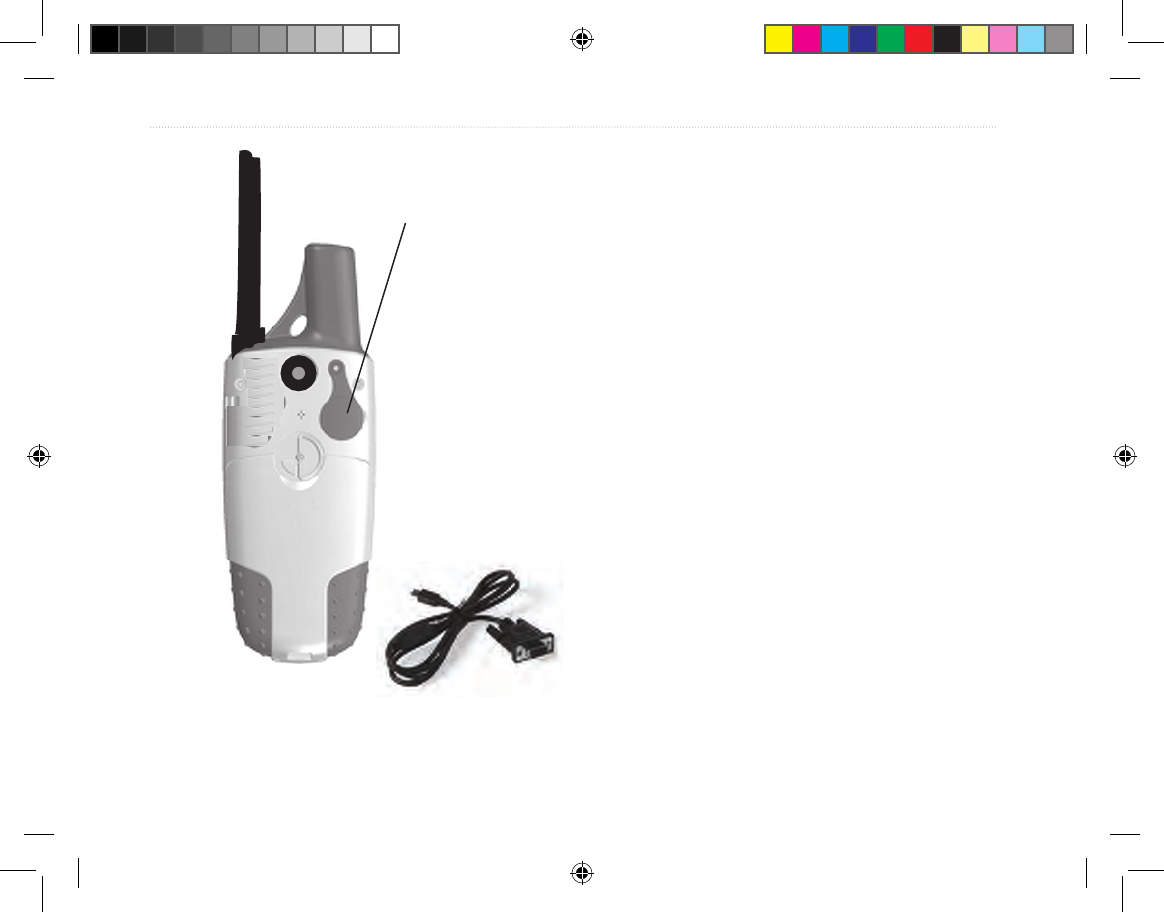
44 Tracking System Owner’s Manual - Draft
appendIx >
Interfacing
The following formats are supported for connection of
external devices.
Garmin Proprietary Sentences—PGRME (estimated
error), PGRMM (datum string), and PGRMZ
(altitude).
The NMEA 0183 version 3.01 interface format is
supported by the Receiver and enables the unit to
drive up to three NMEA devices.
The following are the sentences for NMEA 0183,
version 3.01 output:
Approved sentences—GPGGA, GPGLL, GPGSA,
GPGSV, GPRMB, GPRMC, GPRTE, GPVTG,
GPWPL, GPBOD, and GPAPB.
Data transfer is enabled by using the USB to RS232
Serial Port Cable accessory shown to the left.
USB port under
weather cover
USB to RS232 Serial Port
Data Cable
Tracking System Owner's Manual F44 44 1/16/2007 1:51:49 PM

Tracking System Owner’s Manual - Draft 45
appendIx >
Data Field Denitions
The following list provides a brief denition of each
data eld option.
Accuracy Of GPS—the current accuracy of your GPS-
determined location.
Ambient Pressure—the uncalibrated current pressure.
Ascent - Average—the average vertical distance of ascent.
Ascent - Maximum—the maximum rate in feet per minute.
Ascent - Total—the total distance ascended.
Barometer—the calibrated current pressure.
Bearing—the compass direction from your current position
to a destination point.
Course—
the desired path of travel from your starting point to
your destination point.
Descent - Average—the average vertical distance of descent.
Descent - Maximum—the maximum descent rate in feet
per minute.
Descent - Total—the total distance descended.
Distance - To Next—the distance to the next point on a route.
Distance - To Destination—the entire distance to the end
of a route.
ETA - At Next—the estimated time that you will arrive at
the next point on your route, at current speed and course.
ETA - At Destination—the estimated time that you will
arrive at your destination, at current speed and course.
Elevation—the distance above or below mean sea level.
Elevation - Maximum—the highest elevation reached.
Elevation - Minimum—the lowest elevation reached.
Glide Ratio—the ratio of horizontal distance traveled to
vertical distance.
Glide Ratio To Dest—the glide ratio required to descend
from your position and elevation to the destination’s
elevation.
Heading—your direction of travel as indicated by a
compass, in degrees or cardinal letters (N, S, E, W).
Location (lat/lon)—your current location as latitude and
longitude coordinates.
Location (selected)—your current location described in the
selected units of measure (other than latitude and longitude).
Odometer
—
the total distance you have traveled for all trips.
Tracking System Owner's Manual F45 45 1/16/2007 1:51:49 PM

46 Tracking System Owner’s Manual - Draft
appendIx >
Off Course—the distance off your direct course line.
Pointer—the arrow that indicates the direction to travel to
the next point on a route.
Speed—your current vehicle speed measured in miles per
hour, kilometers per hour, or knots.
Speed - Maximum—the maximum speed you have
attained since the trip computer was reset.
Speed - Moving Avg.—the average speed while your
vehicle was moving.
Speed—Overall Avg.—the average speed determined by
both the moving and stopped time and speed.
Sunrise
—the time of
sunrise for the current date and location.
Sunset—the time of sunset for the current date and location.
Time To Destination
—
the estimated time enroute to your final
destination, if you maintain your current speed and course.
Time To Next
—
the estimated time enroute to the next point
on your route, if you maintain your current speed and course.
Time of Day—the current time and date. It can be
displayed in 12- or 24-hour format in local time or
universal (UTC) time.
To Course—your direction of travel to get back on course.
Trip Odometer—the running total of distance traveled
since the Trip Computer was reset.
Trip Time - Moving—the length of time your vehicle has
been in motion, since the trip computer was reset.
Trip Time - Stopped—the length of time that the vehicle has
been stopped (stationary) while the unit was powered on and
tracking your location (since the trip computer was reset).
Trip Time - Total—the total time the unit has been track-
ing since the trip computer was reset.
Turn—the direction of, and distance to, the next turn on an
active route.
Velocity Made Good—the rate of closure on a destination,
based upon your current speed and course of travel.
Vertical Speed—the rate of altitude gain or loss over time.
Vertical Speed Dest—the measurement of your rate of
ascent or descent to a predetermined altitude.
Water Speed—the measurement of speed over water from
interfaced devices.
Water Temperature—the measurement of water tempera-
ture from interfaced devices.
Waypoint—At Destination—the last point on a route;
your destination.
Waypoint—At Next—the next point on your route.
Tracking System Owner's Manual F46 46 1/16/2007 1:51:49 PM

Tracking System Owner’s Manual - Draft 47
appendIx >
Optional Accessories
Several optional accessories are available to enhance
the operation of the Tracking System.
To obtain replacement parts and optional accessories,
contact your Garmin Dealer, or Garmin Product
Support in the U.S.A. at 800/800.1020, or Garmin
Europe at 44/0870.8501241.
WARNING: Garmin accessories are designed
and tested specically for use with Garmin
products. Accessories offered by other
manufacturers have not been tested or approved
for use with Garmin products. Use of such
accessories could cause damage to the Tracking
System and void the terms of the warranty.
Auto Navigation Kit—provides the accessories and
map data for use in an automobile.
12 Volt DC Adapter—provides auxiliary power from
an automobile cigarette lighter.
GA 25MCX Remote GPS Antenna—allows
enhanced satellite acquisition. Includes magnetic
mount and cable.
MapSource Software Data Disks and Pre-Loaded
microSD Cards—offer several detailed mapping
options that are compatible with the Tracking System.
Visit to Garmin Web site at www.garmin.com for a
list of compatible MapSource products.
Marine Mount Kit—allows installation on a boat.
Automotive Mount Kit—allows installation on an
automobile dash. (Does not include mapping data).
Automotive Windshield Suction Mount Kit—
allows installation on an automobile windshield.
For a complete list of available accessories for use
with the Trackiing System, refer to the Garmin Web
site: http://garmin.com/products/gpsmap60csx/.
Tracking System Owner's Manual F47 47 1/16/2007 1:51:49 PM

48 Tracking System Owner’s Manual - Draft
appendIx >
Connecting Your Receiver to a Com-
puter
You can connect your Receiver to your computer
using either a serial port or USB connector cable.
NOTE: Fully install the supplied MapSource
Trip & Waypoint Manager software on your
computer before connecting the USB cable to the
computer. Follow the instructions for installation
and operation provided with the software.
To connect your Receiver to your
computer:
1. Lift the USB protective cover from the back of
the Receiver, and insert the smaller connector
on the USB cable into the matching port.
2. Connect the remaining cable end to your
computer's USB port.
To connect to your computer using a Serial
Port connector:
1. Lift the Serial Port protective cover from the
back of the Receiver, and insert the round
indexed connector on the cable into the
matching port.
2. Connect the remaining cable end to your PC
Serial port or other appropriate device.
3. Set your Receiver interface setting to the
appropriate interface format. Refer to Interface
Setup on page 68.
Information about USB Drivers
The USB drivers are automatically installed when you
install the MapSource Trip and Waypoint Manager
software that came with your Receiver. When you
initially connect the Receiver to a USB port, your
computer might prompt you to locate the destination
of the drivers for the device. You only need to install
the drivers once. After the drivers are installed,
your computer always detects your Receiver when
it is connected. USB drivers might be updated
periodically. You can nd updates at www.garmin.
com.
Tracking System Owner's Manual F48 48 1/16/2007 1:51:49 PM

Tracking System Owner’s Manual - Draft 49
appendIx >
What Is WAAS/EGNOS?
The Wide Area Augmentation System (WAAS) is an
FAA funded service to improve the overall integrity
of the GPS signal for users in North America. The
European Geostationary Navigation Overlay Service
(EGNOS) is the European version of WAAS and
operates in the same manner.
WAAS is made up of satellites and ground reference
stations positioned across the United States that
monitor GPS satellite data. Master stations, located on
either coast, collect data from the reference stations
and create a GPS data correction message. Master
station uplinks the correction message to the WAAS
GEO satellites using a ground uplink station. Then
WAAS GEO satellites broadcast the WAAS corrected
signal to user in the service area.
According to the FAA’s Web site, testing of WAAS in
September 2002 confirmed an accuracy performance
of 1-2 meters horizontal and 2-3 meters vertical
throughout the majority of the continental United
States and portions of Alaska.
WAAS and EGNOS are just two service providers
that adhere to the MOPS (Minimum Operational
Performance Standard) for global satellite based
augmentation systems (SBAS). Eventually there
are to be several more services of worldwide
geostationary communication satellites that broadcast
integrity information and differential correction data
as transmitted by ground reference stations.
All SBAS systems use the same receiver frequency;
therefore, any operational SBAS system should be
capable of providing your GPS unit with increased
accuracy at any location in the world.
Currently, enabling WAAS on your Receiver in
regions that are not supported by ground stations, may
not improve accuracy, even when receiving signals
from an SBAS satellite. In fact, it can degrade the
accuracy to less than that provided by GPS satellites
alone. For this reason, when you enable WAAS on
your Garmin GPS receiver, the receiver automatically
uses the method that achieves the best accuracy. For
more information, go to http://gps.faa.
gov/Programs/WAAS/waas.htm.
Tracking System Owner's Manual F49 49 1/16/2007 1:51:49 PM
50 Tracking System Owner’s Manual - Draft
appendIx >
Map Datums and Location
Formats
What Are Map Datums?
A datum is a mathematical model of the Earth that
approximates the shape of the Earth, and enables
calculations to be carried out in a consistent and
accurate manner. The datum is physically represented
by a framework of ground monuments whose
positions have been accurately measured and
calculated on this reference surface. Lines of latitude
and longitude on a map or chart are referenced to a
speci c map datum. Every chart has a map datum
reference and the Receiver can be set to match most
of those commonly used.
If you are navigating and comparing the GPS
coordinates to a map, chart, or other reference, set the
map datum in the GPS unit to the same datum as the
map to ensure the most accurate navigation.
What Is a Location Format?
Your current location is viewed on the GPS in the
form of coordinates. Because different maps and
charts use different location formats, Garmin GPS
units allow you to choose the correct coordinate
system for the type of map you are using. The most
common format is latitude and longitude, which is
used by all Garmin units.
You can choose to change the location format for other
coordinate systems. UTM/UPS (Universal Transverse
Mercator/Universal Polar Stereographic) projection
formats are easy-to-use metric grids that are found on
most USGS topographic quadrangle maps. You can
also select one of several other grids, including a user-
de nable grid (for the advanced user).
Map Datums are based on a
mathematical model of the Earth.
Tracking System Owner's Manual F50 50 1/16/2007 1:51:50 PM
Tracking System Owner’s Manual - Draft 51
appendIx >
FCC Compliance
This device complies with Part 15 of the FCC rules.
Operation is subject to the following two conditions:
(1) this device may not cause harmful interference,
and (2) this device must accept any interference
received, including interference that may cause
undesired operation.
This equipment generates, uses, and can radiate radio
frequency energy and may cause harmful interference
to radio communications if not installed and used
in accordance with the instructions. However, there
is no guarantee that interference will not occur in a
particular installation. If this equipment does cause
harmful interference to radio or television reception,
which can be determined by turning the equipment
off and on, the user is encouraged to try to correct the
interference by one of the following measures:
• Reorient or relocate the receiving antenna.
• Increase the separation between the equipment
and the receiver.
• Connect the equipment into an outlet on a
circuit different from that to which the receiver
is connected.
• Consult the dealer or an experienced radio/TV
technician for help.
NOTE: THE MANUFACTURER IS NOT
RESPONSIBLE FOR ANY RADIO OR TV
INTERFERENCE CAUSED BY UNAUTHORIZED
MODIFICATIONS TO THIS EQUIPMENT. SUCH
MODIFICATIONS COULD VOID THE USER’S
AUTHORITY TO OPERATE THE EQUIPMENT.
Tracking System Owner's Manual F51 51 1/16/2007 1:51:50 PM

52 Tracking System Owner’s Manual - Draft
appendIx >
Limited Warranty
This Garmin product is warranted to be free from
defects in materials or workmanship for one year from
the date of purchase. Within this period, Garmin will
at its sole option repair or replace any components
that fail in normal use. Such repairs or replacement
will be made at no charge to the customer for parts or
labor, provided that the customer shall be responsible
for any transportation cost. This warranty does not
cover failures due to abuse, misuse, accident or
unauthorized alteration or repairs.
THE WARRANTIES AND REMEDIES
CONTAINED HEREIN ARE EXCLUSIVE AND IN
LIEU OF ALL OTHER WARRANTIES EXPRESS
OR IMPLIED OR STATUTORY, INCLUDING ANY
LIABILITY ARISING UNDER ANY WARRANTY
OF MERCHANTABILITY OR FITNESS FOR
A PARTICULAR PURPOSE, STATUTORY OR
OTHERWISE. THIS WARRANTY GIVES YOU
SPECIFIC LEGAL RIGHTS, WHICH MAY VARY
FROM STATE TO STATE.
I
N NO EVENT SHALL GARMIN BE LIABLE
FOR ANY INCIDENTAL, SPECIAL, INDIRECT
OR CONSEQUENTIAL DAMAGES, WHETHER
RESULTING FROM THE USE, MISUSE, OR
INABILITY TO USE THIS PRODUCT OR FROM
DEFECTS IN THE PRODUCT. Some states do not
allow the exclusion of incidental or consequential
damages, so the above limitations may not apply to you.
Garmin retains the exclusive right to repair or replace
the unit or software or offer a full refund of the
purchase price at its sole discretion. SUCH REMEDY
SHALL BE YOUR SOLE AND EXCLUSIVE
REMEDY FOR ANY BREACH OF WARRANTY.
To obtain warranty service, contact your local Garmin
authorized dealer or call Garmin Product Support for
shipping instructions and an RMA tracking number.
The unit should be securely packed with the tracking
number clearly written on the outside of the package.
The unit should then be sent, freight charges prepaid,
to any Garmin warranty service station. A copy of
the original sales receipt is required as the proof of
purchase for warranty repairs.
Tracking System Owner's Manual F52 52 1/16/2007 1:51:50 PM

Tracking System Owner’s Manual - Draft 53
appendIx >
Garmin International, Inc.
1200 E 151st Street, Olathe, Kansas 66062 U.S.A.
Tel. 913/397.8200
Fax. 913/397.8282
Garmin (Europe) Ltd.
Unit 5, The Quadrangle, Abbey Park Industrial Estate,
Romsey, SO51 9DL U.K.
Tel. 44/0870.8501241
Fax 44/0870.8501251
Online Auction Purchases: Products sold through
online auctions are not eligible for rebates or
other special offers from Garmin. Online auction
conrmations are not accepted for warranty
verication. To obtain warranty service, an original or
copy of the sales receipt from the original retailer is
required. Garmin will not replace missing components
from any package purchased through an online
auction.
International Purchases: A separate warranty
is provided by international distributors for units
purchased outside the United States. This warranty
is provided by the local in-country distributor and
this distributor provides local service for your unit.
Distributor warranties are only valid in the area of
intended distribution. Units purchased in the United
States or Canada must be returned to the Garmin
service center in the United Kingdom, the United
States, Canada, or Taiwan for service.
The Garmin Receiver has no user-serviceable parts.
Should you ever encounter a problem with your unit,
please take it to an authorized Garmin dealer for
repairs.
The Receiver is fastened shut with screws. Any
attempt to open the case to change or modify the unit
in any way will void your warranty and may result in
permanent damage to the equipment.
Tracking System Owner's Manual F53 53 1/16/2007 1:51:50 PM

54 Tracking System Owner’s Manual - Draft
Index
Index
A
accessories 46
altimeter 28–32
altimeter page 28
calibration 30
data elds 30
options menu 29
pressure/elevation plots 29
reset options 30
view points 30
zoom ranges 30
altitude 28–32
appendix 43
B
backlight 5
battery installation 2, 4
bearing pointer 28
C
calendar 41
calibrate
electronic compass 27
calibration setup 38
cautions x
cleaning viii
compass
calibration 27
compass page 26
electronic compass 26
options menu 27
Course Deviation Indicator (CDI)
28
course pointer 28
creating and using waypoints 14
creating a waypoint using coordi-
nates 14
creating waypoints using the
map 14
D
data eld denitions 44
deleting waypoints 14
display setup 34
E
editing waypoints 14
elevation, GPS 21
entering data 8
ENTER key 3
F
elds, data 29
nd 16
by name 16
information pages 16
recent nds 16
FIND/MOB key 3
nding
an address 17
an intersection 17
an interstate exit 16
a city 16
a geocache 16
a point of interest 17
a waypoint 16
FIND key 3
nd menu 15
G
geocache setup 36
guidance text 23
H
highway page 33
I
IN/OUT Zoom keys 3
initializing the GPS receiver 6
installing the lanyard 2
J
jumpmaster 38
L
lanyard installation 2
location formats 50
M
main menu 32
calendar 41
highway page 33
proximity waypoints 41
set up menu
calibration setup 38
display setup 34
geocache setup 36
heading setup 37
Jumpmaster 38
Tracking System Owner's Manual F54 54 1/16/2007 1:51:50 PM

Tracking System Owner’s Manual - Draft 55
Index
marine setup 36
page sequence setup 35
system setup 33
time setup 37
tones setup 35
units setup 37
sun and moon 41
tracks page 32
main pages 20
manual conventions i
MapSource 48
map datums 50
map page 21
additional map data 22
declutter 25
options menu 23
orientation 23
setup 24
zoom range 22
map setup 24
marine setup 36
marking your current location 14
MARK key 3
measure distance 23, 25
MENU key 3
N
north up/track up 21
O
on-screen messages 9
P
PAGE/COMPASS key 3
page sequence setup 35
POWER key 3, 5
pressure plots, view 29
product registration v
prole eld 29
proximity waypoints 41
Q
QUIT key 3
R
ROCKER key 3
routes 18
copying 20
creating 18
editing 19
navigating 19
routing setup 35
S
satellite page 20
selecting options 8
Sight ‘N Go 28
software license agreement v
status bar 8
stop (resume) navigation 23
storage viii
sun and moon 41
system setup 33
T
terminology 7
time setup 37
tones setup 35
tracks 17, 32
navigating 18
proles 18
track up/north up 21
transferring data to a microSD
card 10
trip & waypoint manager 48
trip computer page 31
U
units setup 37
unit overview 1, 4
USB mass storage 35
using the keypad 3
W
WAAS/EGNOS 49
warnings ix
warranty 52
waypoints 14
Averaging a location 14
Creating 14
Editing 14
Man Overboard 15
Projecting 15
Z
zooming in and out 22
zoom range 22
Tracking System Owner's Manual F55 55 1/16/2007 1:51:50 PM

Tracking System Owner's Manual F56 56 1/16/2007 1:51:50 PM

Tracking System Owner's Manual F57 57 1/16/2007 1:51:51 PM
For the latest free software updates (excluding map data) throughout the life of your
Garmin products, visit the Garmin Web site at www.garmin.com.
© 2007 Garmin Ltd. or its subsidiaries
Garmin International, Inc.
1200 East 151st Street, Olathe, Kansas 66062, U.S.A.
Garmin (Europe) Ltd.
Unit 5, The Quadrangle, Abbey Park Industrial Estate, Romsey, SO51 9DL, U.K.
Garmin Corporation
No. 68, Jangshu 2nd Road, Shijr, Taipei County, Taiwan
www.garmin.com
Part Number 190-00714-00 Draft Rev B
Tracking System Owner's Manual F58 58 1/16/2007 1:51:51 PM