Garmin 01179 Remote Transceiver User Manual 190 00355 02 0F
Garmin International Inc Remote Transceiver 190 00355 02 0F
Garmin >
Contents
- 1. Install Manual Cover and Info
- 2. Install Manual Sect 1
- 3. Install Manual Sect 2
- 4. Install Manual Sect 3 and 4
Install Manual Sect 1

GDL 69/69A Installation Manual Page 1-1
190-00355-02 Rev. F
1 GENERAL DESCRIPTION
1.1 Scope
The information in this manual is STC approved (STC #SA01487SE). Only the equipment interfaces
covered in this manual are within the scope of this STC. Other equipment may be suitable for use with
the GDL 69/69A, but use of such equipment is beyond the scope of this STC. Additional FAA approval
may be required if equipment not covered in this manual is used to interface to the GDL 69/69A.
This document describes the GDL 69/69A operating with software version 2.13 or later, and the optional
GRT 10/GRC 10 wireless remote system.
Refer to Section 6, Limitations for additional information.
It is possible for installers to seek evaluation and approval of an alternate installation by means of the
field approval process. This manual and all the data contained within may be used by the installer in
pursuit of a field approval.
1.2 Introduction
This manual presents mechanical and electrical installation requirements for installing the datalink
equipment used to deliver XM WX Satellite Weather™ to a variety of Garmin navigation systems. For
audio entertainment in the cockpit, the GDL 69A also provides XM Satellite Radio. If equipped with the
optional GRT 10/GRC 10 wireless remote system, passengers are able to remotely control the audio
functions of the GDL 69A datalink receiver using the GRC 10 wireless remote.
Equipment needed for receiving XM weather and radio:
GDL 69/69A – (datalink receiver)
GA37, GA 55, or GA55A (XM antenna)
GRT 10 (transceiver) –optional
GRC 10 (remote control) – optional
The datalink equipment will operate with any of the following systems or displays. For a complete list of
equipment see Table 1-1.
400W/500W series displays
400/500 series displays
MX20 Multi-Function Display (MFD)
GMX 200 MFD
G1000 Integrated Cockpit System (GDU 104x)
The GDL 69/69A can be integrated into a variety of airframes under an appropriate TC or STC. Each
airframe installation may vary. Interconnect drawings and procedures that are approved by the aircraft-
manufacturer should be used during actual installation.
1.3 Equipment Description
The GDL 69/69A is an XM Satellite Radio data link receiver. The XM Satellite Radio antenna receives
the XM satellite signal and passes it to the GDL 69/69A. The GDL 69 is a weather data receiver and the
GDL 69A is a weather receiver with the addition of XM Satellite Radio audio entertainment. For display
of weather information and control of audio channel and volume, the GDL 69/69A may be interfaced to
the GMX 200 or MX20 MFD or 400/500, 400W/500W series units via an RS-232 bus or the GDU104x
via an Ethernet link. Audio volume and channel changes may also be controlled with mounted optional
switches located in the cabin or by remotely using the GRC 10 wireless remote. The GDL 69A may also
be interfaced to a Garmin audio panel for amplification and distribution of the audio signal.
General Description
Page 1-2 GDL 69/69A Installation Manual
Rev. F 190-00355-02
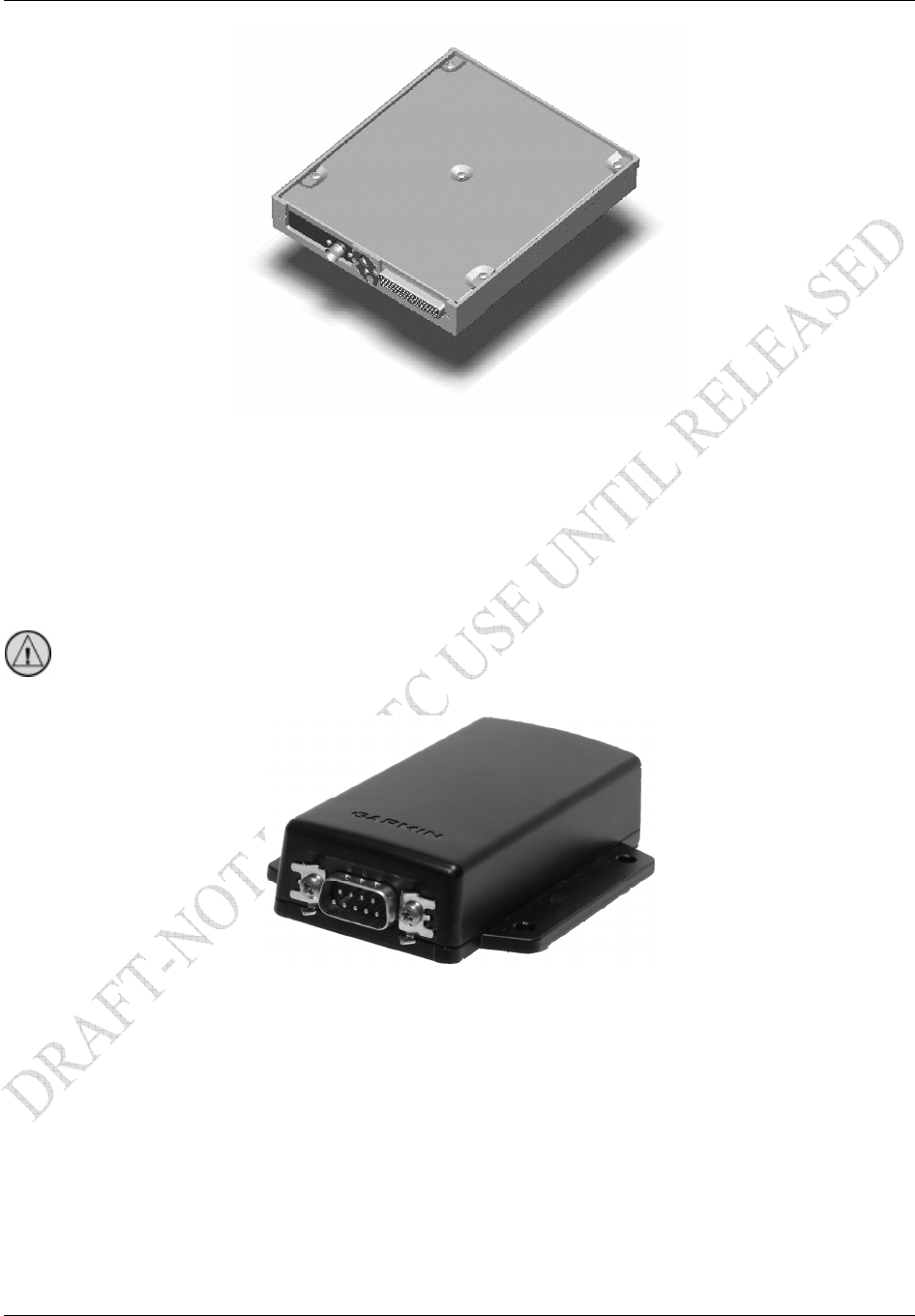
Figure 1-1. GDL 69/69A Unit View
The optional GRT 10/GRC 10 wireless remote system is for use by passengers in the aircraft to control
the audio functions of the Garmin GDL 69A Datalink Receiver. The system consists of two components:
(1) The GRT 10 Wireless Transceiver installed in the aircraft and connected to the GDL 69A serial port,
and (2) the GRC 10 Wireless Remote with an LCD display.
CAUTION
Other transmitting systems which may exist in the aircraft:
Bluetooth and other non-aviation transmitters require separate authorization for use in an
aircraft. If they are present, note that interference from such devices may degrade the
performance of the GRT 10/GRC 10 wireless remote system.
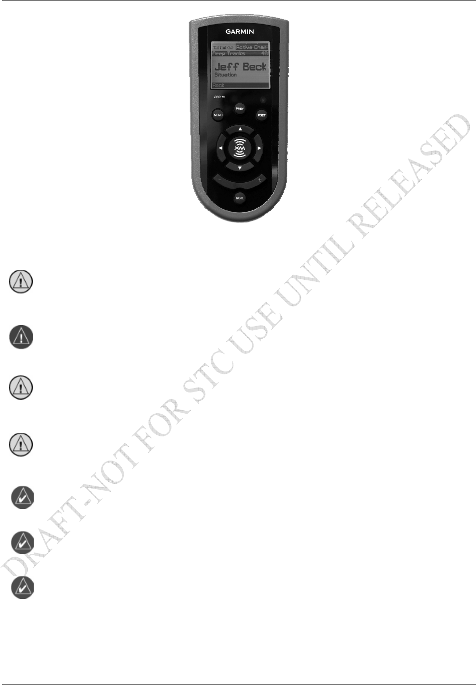
Figure 1-2. GRT 10 Transceiver Unit View
General Description
GDL 69/69A Installation Manual Page 1-3
190-00355-02 Rev. F
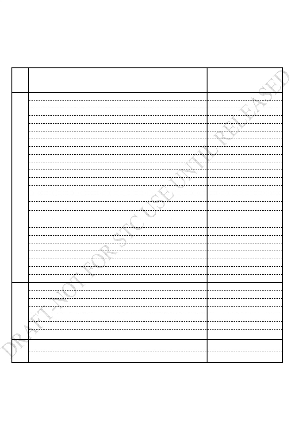
Figure 1-3. GRC 10 Remote Control Unit View
CAUTION
Stow the GRC 10 in a secure location (i.e. glove box, seat back pocket, etc.) when not in
use to prevent damage to the aircraft interior or injury to occupants caused by aircraft
maneuvers.
WARNING
Do not use lithium batteries in the GRC 10.
CAUTION
When replacing batteries, use only new or fully charged batteries. Do not mix new and
old batteries as this can cause battery leakage and damage to the unit. Do not mix battery
types (i.e. rechargeable with non-rechargeable).
CAUTION
Remove batteries if the unit will not be in use for several months. Storing batteries in the
unit for prolonged periods may result in leakage and damage to the battery compartment.
NOTE
Failure of the GRC 10 (i.e. dead batteries) has no impact on normal aircraft operations
and is only used for passengers to control audio entertainment.
NOTE
The USB Port on the GRC 10 is for factory use only.
NOTE
The GRC 10 is paired to the aircraft’s GRT 10 at installation. The GRC 10 will not
control the XM audio functions of another aircraft.
General Description
Page 1-4 GDL 69/69A Installation Manual
Rev. F 190-00355-02
1.4 Interfaced Equipment
Accomplishment of installation of the GDL 69/69A under this STC requires previous or concurrent
installation of the following equipment. If installing the model GDL 69, a control display unit is required.
If installing a GDL 69A, a control display unit and audio panel is required; the GRT 10/GRC 10 wireless
remote system is optional.
Table 1-1. GDL 69/69A Interfaced Equipment List
Description
Software Version
(Or later FAA
approved version)
GMX 200 MFD Control Display Unit Ver. 2.0
MX20 MFD Control Display Unit 5.5
GDU 1040 MFD Control Display Unit 4.01
GDU 1042 MFD Control Display Unit 5.00
GDU 1043 MFD Control Display Unit 5.00
GPS 400* 4.04
GPS 400W 2.00
GNC 420* 4.04
GNC 420W 2.00
GNC 420A* 4.04
GNC 420AW 2.00
GNS 430* 4.04
GNS 430W 2.00
GNS 430A* 4.04
GNS 430AW 2.00
GPS 500* 5.04
GPS 500W 2.00
GPS 500W with TAWS 2.00
GNS 530* 5.04
GNS 530W 2.00
GNS 530W with TAWS 2.00
GNS 530A* 5.04
GNS 530AW 2.00
OR
GNS 530AW with TAWS 2.00
SL15 Audio Panel Unit N/A
SL15M Audio Panel Unit N/A
SL10 Audio Panel Unit N/A
SL10S Audio Panel Unit N/A
SL10MS Audio Panel Unit N/A
GMA 340 Audio Panel Unit N/A
OR
GMA 1347 Audio Panel Unit N/A
GRC 10 Remote 2.00
OR
GRT 10 Transceiver 2.00
*400/500 series units must use Pilot Guide Addendum 190-00140-13 Revision D, or
later. 400/500 series units may be connected to a GDL 69A. The 400/500 series units do
not have audio control capabilities, but the aircraft may be provisioned with a GDL 69A
and wiring for future 400W/500W series upgrade that will provide audio control and
display.

General Description
GDL 69/69A Installation Manual Page 1-5
190-00355-02 Rev. F
1.5 Audio Entertainment Installation Limitations
The GDL 69A XM Satellite Radio audio entertainment and optional GRT 10/GRC 10 wireless remote
system may be installed to all passenger locations for all aircraft on the STC Approved Model List
(AML). XM audio entertainment to crew locations depends on aircraft installation, which must meet
requirements of 14 CFR §23.1431(e).
For purpose of this STC, 14 CFR §23.1431(e) requires that each pilot station must be able to hear the
aircraft’s stall warning horn with the entertainment system audio set to the maximum pilot controllable
setting. This also applies to aircraft with a gear extension warning horn. Aircraft which have electric
stall/gear warning may utilize the GDL 69A audio suppression discrete input to turn off the music during
an event. For these installations, the XM audio may be provided to the crew locations.
For aircraft installations with non-electric stall/gear warning horns, this STC does not provide data for
installation of audio entertainment to crew locations. The GDL 69A audio entertainment may not be
wired to crew locations without a separate evaluation that is beyond the scope of this STC. It is possible
for installers to seek evaluation and approval of an alternate installation by means of the field approval
process. Each installation or aircraft type must be evaluated for compliance with 14 CFR §23.1431(e).
This evaluation may determine that the required horns can be heard satisfactorily without disabling the
GDL 69A audio entertainment to the crew.
The optional GRT 10/GRC 10 wireless remote system has been tested for interference as part of the STC.
Its operation must not interfere with the proper operation of any required aircraft equipment or systems.
STC installation requires that the installer verify that there is no interference using the post-installation
check-out procedure detailed in Section 4. Operators may use the STC qualification of the device as a
basis for showing compliance with 14 CFR Part 91.21.

General Description
Page 1-6 GDL 69/69A Installation Manual
Rev. F 190-00355-02
1.6 XM Satellite Radio
Welcome to the Next Generation of Radio. America’s most popular satellite radio service gives you the
power to choose what you want to hear - wherever and whenever you want it around the Continental
United States.
XM Satellite Radio provides commercial-free music channels, channels of news, sports, talk and
entertainment, dedicated channels of instant traffic and weather, the deepest play list in the industry with
access to over 2 million titles, and coast-to-coast coverage. XM features digital quality audio.
Subscriptions to XM Satellite Radio weather and audio entertainment services are required before the
GDL 69/69A can be activated for the first use. Refer to Section 4.8 for instructions for activating your
unit.
NOTE
It is prohibited to copy, decompile, disassemble, reverse engineer, or manipulate any
technology incorporated in receivers compatible with the XM Satellite Radio system.
Furthermore, the AMBE(R) voice compression software included in this product is
protected by intellectual property rights including patent rights, copyrights, and trade
secrets of Digital Voice Systems, Inc. The user of this or any other software contained in
an XM Satellite Radio is explicitly prohibited from attempting to copy, decompile,
reverse engineer, or disassemble the object code, or in any other way convert the object
code into human-readable form. The software is licensed solely for use within this
product.
1.7 Interface Summary
The following list is an interface summary for the GDL 69/69A units. Note that the GDL 69 does not
have the audio interface.
3 RS-232 Inputs/Outputs
4 Ethernet Inputs/Outputs
5 Audio Discrete Control Inputs (Volume Up, Volume Down, Channel/Preset Up, Channel/Preset
Down, Mute)
6 Audio Suppression Inputs (3 Active High, 3 Active Low)
1 Stereo Audio Output (Left Audio, Right Audio with internal volume control and audio
suppression)
1 Stereo Monitor Output (Line Out Left, Line Out Right with fixed volume level and no audio
suppression)
1 Remote Power On/Off Discrete Input
2 Discrete Inputs (Reserved for Manufacturing Use – Test, Debug Port Enable)
1 Discrete Input (Configures audio channel control inputs)
Configuration Module (for storing aircraft configuration data)
Aircraft Power Input (Power-on controlled by aircraft avionics power bus)
The following list is an interface summary for the GRT 10 Wireless Transceiver:
1 RS-232 Input/Output
1 Discrete Input (Volume Lock Enable)
Aircraft Power Input (Power-on controlled by aircraft avionics power bus)
General Description
GDL 69/69A Installation Manual Page 1-7
190-00355-02 Rev. F
1.8 Technical Specifications
The GDL 69/69A, GA 55, and GA55A antenna, and optional GRT 10/GRC 10 wireless remote system
are PMA approved and there is no applicable TSO. The GA 37 and GA 57 GPS/WAAS – XM antennas
are TSO authorized under TSO-C144, but the GA 57 is not recommended for new installations. It is the
responsibility of those desiring to install this equipment either on or within a specific type of class of
aircraft to determine that the aircraft installation standards are within the prescribed standards. The
following table presents general environmental specifications. For detailed specifications, see the
Environmental Qualification form in Appendix B.
Table 1-2. GDL 69/69A Specifications
GDL 69/69A Characteristics Specification
Operating Temperature Range -45° C to +70° C
Input Voltage Range 9.0 to 33.0 VDC
Software Compliance RTCA DO-178B Level D
Environmental Compliance RTCA DO-160D
Table 1-3. GA 37, GA 55, GA 55A, and GA 57 Specifications
GA 37, GA 55, GA 55A Characteristics Specification
Operating Temperature Range -55° C to +85° C
Input Voltage Range Power provided by GDL 69/69A.
Software Compliance None
Environmental Compliance RTCA DO-160D
Table 1-4. GRC 10 Remote Control Specifications
GRC 10 Remote Control Characteristics Specification
Operating Temperature Range -20° C to +55° C
Input Voltage Range Power provided by 2 AA batteries
Software Compliance RTCA DO-178B Level D
Environmental Compliance RTCA DO-160E
Table 1-5. GRT 10 Transceiver Specifications
GRT 10 Transceiver Characteristics Specification
Operating Temperature Range -30° C to +70° C
Input Voltage Range 9.0 to 33.0 VDC
Software Compliance RTCA DO-178B Level D
Environmental Compliance RTCA DO-160E
General Description
Page 1-8 GDL 69/69A Installation Manual
Rev. F 190-00355-02
NOTE
See Table 2-12 outlining weights for the GDL 69, GDL 69A, remote rack, modular rack,
GRT 10 transceiver, and GRC 10 remote control.
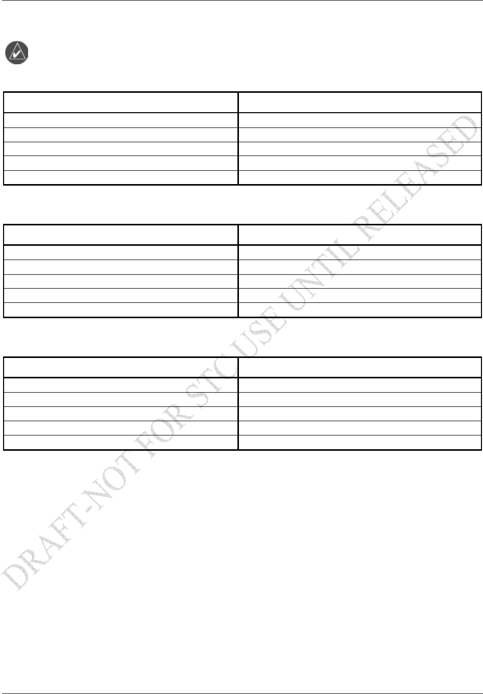
Table 1-6. GDL 69/69A Unit Dimensions
Characteristic Specification
Width 1.05 inches (2.66 cm)
Height 6.15 inches (15.62 cm)
Depth (Rack w/ Connectors) 7.20 inches (18.26 cm)
Unit Weight (GDL 69A) 1.86 lbs (0.84 kg)
Unit (GDL 69A) and Remote Rack Weight 2.83 lbs (1.27 kg)
Table 1-7. GRT 10 Transceiver Dimensions
Characteristic Specification
Width 2.74 inches (7.0 cm)
Height 0.92 inches (2.3 cm)
Length 3.93 inches (10.0 cm)
Unit Weight (excluding connector kit) 0.15 lbs (0.07 kg)
Unit Weight (including connector kit) 0.27 lbs (0.12 kg)
Table 1-8. GRC 10 Remote Control Dimensions
Characteristic Specification
Width 2.46 inches (6.2 cm)
Height 1.16 inches (2.9 cm)
Length 5.00 inches (12.7 cm)
Unit Weight (with batteries) 0.34 lbs (0.15 kg)
Unit Weight (without batteries) 0.23 lbs (0.11 kg)
General Description
GDL 69/69A Installation Manual Page 1-9
190-00355-02 Rev. F
0.49 [12.4]
8.74 [221.9]
8.26 [209.8]
6.91 [175.6]
0.73 [18.49]
4.46 [113.22]
1.60
[40.53]
0.37
[9.40]
1.48
[37.7]
ANTENNA
6.43
[163.2]
7.9 [200.9]
3.98 [101.1]
CENTER OF GRAVITY
3.57 [90.7]
CENTER OF
GRAVITY
0.73 [18.6]
J1100
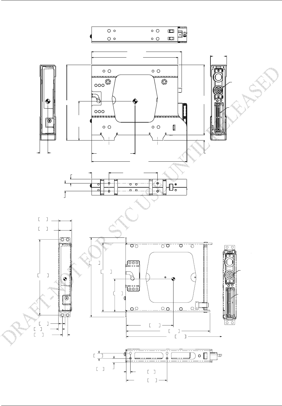
Figure 1-4. GDL 69/69A Remote Rack Unit Dimensions
6.30 160.0
7.26 184.4
7.65 194.3
8.73 221.8
4.30 109.2
3.00 76.2
6.90 175.3
TYP
.36 TYP9.1
.48 TYP12.2
1.20 30.5
WITHOUT DIMPLES
1.23 31.1
WITH DIMPLES
.60 15.2
.48 TYP12.2
.36 TYP9.1
4X .38 9.6
4X 3.73 94.7
J10001
A
NTENNA
Figure 1-5. GDL 69/69A Modular Rack Unit Dimensions
General Description
Page 1-10 GDL 69/69A Installation Manual
Rev. F 190-00355-02
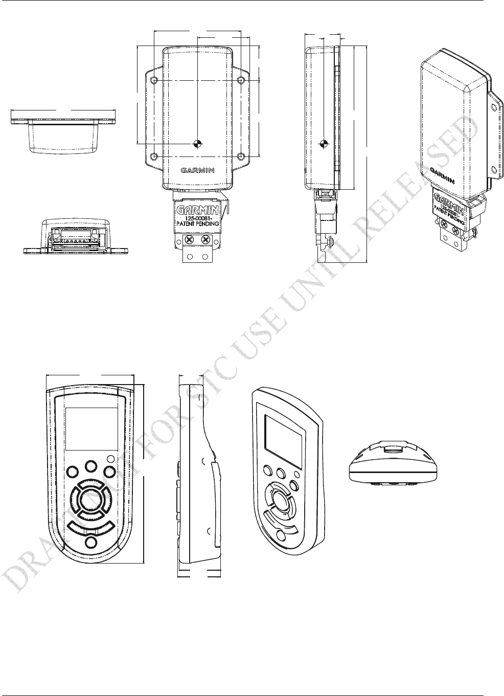
2.74
2.28 0.92
0.43
3.77
5.68
2.00
0.91
1.37
2.57
Figure 1-6. GRT 10 Transceiver Dimensions
2.46
0.68
5.00
1.16
1.20
Figure 1-7. GRC 10 Remote Control Dimensions
General Description
GDL 69/69A Installation Manual Page 1-11
190-00355-02 Rev. F
General Antenna Requirements
Garmin recommends the Garmin XM antenna shown in the Table 1-9 below. These antennas are
approved with the certification of the GDL 69/69A. However, any equivalent XM antenna with
specifications listed in Table 1-10 should work with the GDL 69/69A. Antennas must provide protection
from direct lightning strikes. This STC does not support installations of equivalent antennas.
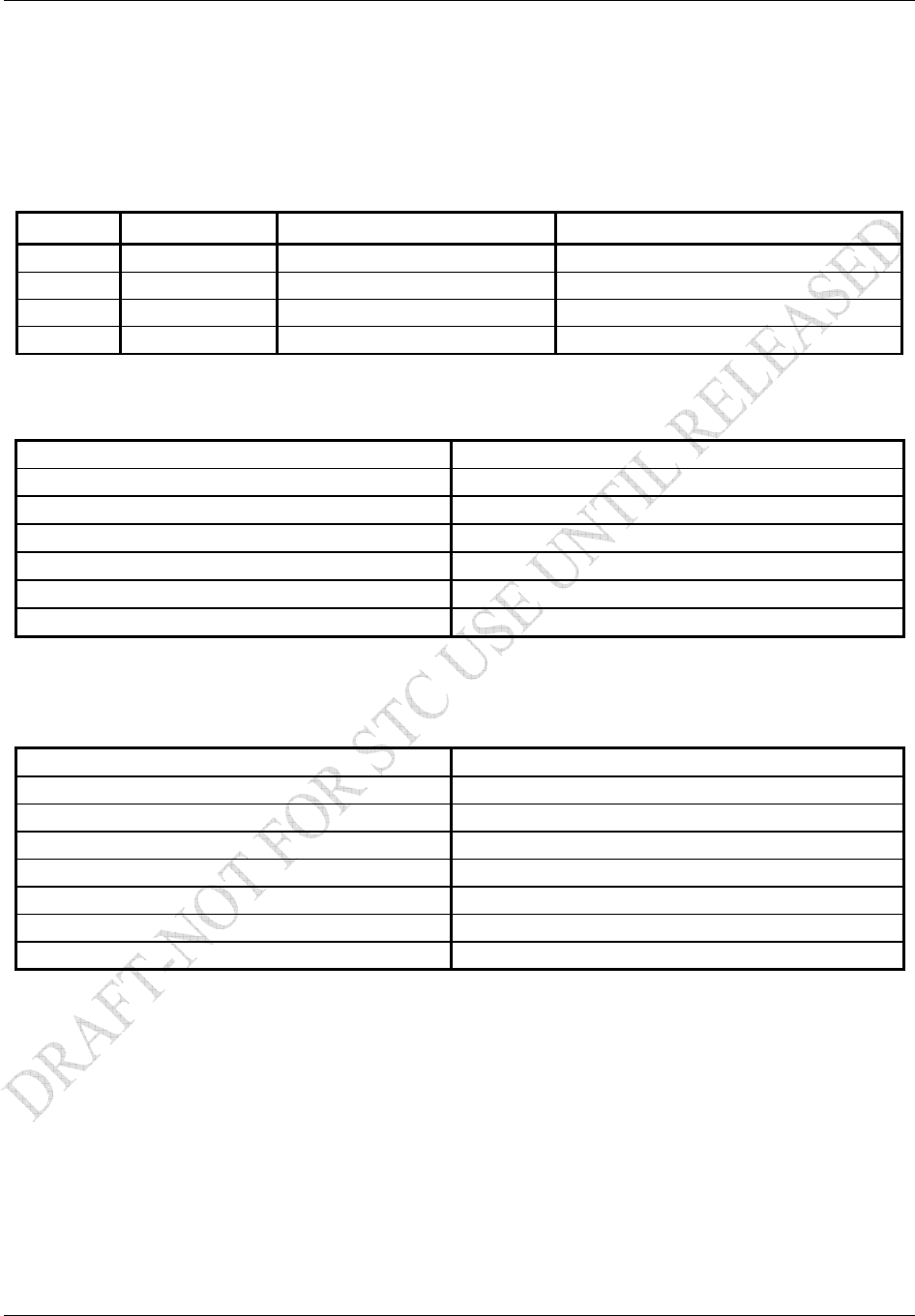
Table 1-9. XM Antennas
Model Part Number Description Mounting Configuration
GA 37 013-00245-00 GPS/WAAS Tear-drop
GA 55 011-01033-00 XM Antenna Stud mount Tear-drop form factor
GA 55A 011-01153-00 XM Antenna Thru-mount (ARINC 743 style mount)
GA 57* 011-01032-00 GPS/WAAS + XM Antenna Thru-mount (ARINC 743 style mount)
* Not recommended for new installations
Table 1-10. XM Satellite Radio Antenna Minimum Requirements
Frequency Range 2332.5 to 2345 MHz
Gain (Typical) 24 dB ± 1 dB**
Noise Figure <1.2 dB
Nominal Output Impedance 50 ohms
Supply Voltage 3.6 to 5.5 VDC
Supply Current (maximum) 55 mA
Operating Temperature Gain -50 to +85°C
** For each 1 dB gain over 24 dB, add 1 dB of attenuation into the antenna cable path
between the antenna and the GDL 69/69A.
Table 1-11. GA 37, GA 55, and GA 55A XM Antenna Specifications
Frequency Range 2332.5 to 2345 MHz
Gain 25 ± 2 dB
Noise Figure <1.2 dB
Nominal Output Impedance 50 ohms
Supply Voltage 3.6 to 5.5 VDC
Supply Current 40 to 55 mA
Operating Temperature Range -50 to +85 ° C
Output Connector TNC
General Description
Page 1-12 GDL 69/69A Installation Manual
Rev. F 190-00355-02
1.9 Reference Documents
The following publications are sources of additional information for installing the GDL 69/69A and
optional GRT 10/GRC 10 wireless remote system. Before installing the GDL 69/69A, the technician
should read all referenced materials applicable to the installation along with this manual.
Table 1-12. Referenced Publications
Part Number Document
190-00149-01 GMA 340 Audio Panel Installation Manual
190-00303-20 GMA 1347 Audio Panel Installation Manual
190-00181-02 500 Series Installation Manual
190-00140-02 400 Series Installation Manual
190-00140-13 400/500 Series Garmin Optional Displays
190-00356-02 400W Series Installation Manual
190-00357-02 500W Series Installation Manual
190-00303-01 GDU 1040 Installation Manual
190-00522-01 GA 55A, GA 56A and GA 57 Antenna Installation Manual
190-00848-00 GA 35, GA 36, and GA 37 Antenna Installation Manual
190-00355-04 XM™ Satellite Radio Activation Instructions
190-00607-04 GMX 200 Installation Manual
560-1025-( ) MX20 Installation Manual
560-0979-( ) SL15 Audio Panel Installation Manual
560-0978-( ) SL10 Audio Panel Installation Manual
1.10 Certification
The GDL 69/69A XM Satellite Radios, XM Satellite Radio Antenna and optional GRT 10/GRC 10
wireless remote system have Parts Manufacturing Approval (PMA) for the aircraft listed on the STC
Approved Mode List (AML).
TSO/ETSO Compliance
The GA 37 and GA 57 are TSO-C144 authorized. The GA 57 is not recommended for new installations.
There are no other applicable TSO standards.
Other Regulatory Criteria
1.10.2.1 FCC Compliance Information
The GRT 10 complies with Part 15 of the FCC regulations and with Canada RSS-210.
NOTE
The GRT 10 and GRC 10 have been approved for use in the United States and Canada.

General Description
GDL 69/69A Installation Manual Page 1-13
190-00355-02 Rev. F
1.10.2.2 FCC Grant of Equipment Authorization
GRT 10: FCC ID: IPH-01179
IC: 1792A-01179
NOTE
This device complies with Part 15 of the FCC Rules. Operation is subject to the following
conditions: (1) This device may not cause harmful interference, and (2) this device must accept
any interference received, including interference that may cause undesired operation.
NOTE
This device does not contain any user-serviceable parts. Repairs should only be made by
an authorized Garmin service center. Unauthorized repairs or modifications could result
in permanent damage to the equipment, and void your warranty and your authority to
operate this device under Part 15 regulations.
GRC 10: FCC ID: IPH-01178
IC: 1792A-01178
NOTE
This device complies with Part 15 of the FCC Rules. Operation is subject to the following
conditions: (1) This device may not cause harmful interference, and (2) this device must accept
any interference received, including interference that may cause undesired operation.
NOTE
This device does not contain any user-serviceable parts. Repairs should only be made by
an authorized Garmin service center. Unauthorized repairs or modifications could result
in permanent damage to the equipment, and void your warranty and your authority to
operate this device under Part 15 regulations.
1.11 Unpacking Unit
Carefully unpack the equipment and make a visual inspection of the unit for evidence of damage incurred
during shipment. If the unit is damaged, notify the carrier and file a claim. To justify a claim, save the
original shipping container and all packing materials. Do not return the unit to Garmin until the carrier has
authorized the claim.
Retain the original shipping containers for return shipments. If the original containers are not available, a
separate cardboard container should be prepared that is large enough to accommodate sufficient packing
material to prevent movement.
NOTE
For GRC 10 Users: Record the GRC 10 serial number for installation purposes. See
Section 4.5.

General Description
Page 1-14 GDL 69/69A Installation Manual
Rev. F 190-00355-02
1.12 Warranty Statement
Limited Warranty
This Garmin product is warranted to be free from defects in materials or workmanship for two years (one
year for GRC 10) from the date of purchase. Within this period, Garmin will at its sole option, repair or
replace any components that fail in normal use. Such repairs or replacement will be made at no charge to
the customer for parts or labor, provided that the customer shall be responsible for any transportation cost.
This warranty does not cover failures due to abuse, misuse, accident or unauthorized alteration or repairs.
THE WARRANTIES AND REMEDIES CONTAINED HEREIN ARE EXCLUSIVE AND IN LIEU OF
ALL OTHER WARRANTIES EXPRESS OR IMPLIED OR STATUTORY, INCLUDING ANY
LIABILITY ARISING UNDER ANY WARRANTY OF MERCHANTABILITY OR FITNESS FOR A
PARTICULAR PURPOSE, STATUTORY OR OTHERWISE. THIS WARRANTY GIVES YOU
SPECIFIC LEGAL RIGHTS, WHICH MAY VARY FROM STATE TO STATE.
IN NO EVENT SHALL GARMIN BE LIABLE FOR ANY INCIDENTAL, SPECIAL, INDIRECT OR
CONSEQUENTIAL DAMAGES, WHETHER RESULTING FROM THE USE, MISUSE, OR
INABILITY TO USE THIS PRODUCT OR FROM DEFECTS IN THE PRODUCT. Some states do not
allow the exclusion of incidental or consequential damages, so the above limitations may not apply to
you.
Garmin retains the exclusive right to repair or replace the unit or software or offer a full refund of the
purchase price at its sole discretion. SUCH REMEDY SHALL BE YOUR SOLE AND EXCLUSIVE
REMEDY FOR ANY BREACH OF WARRANTY.
To obtain warranty service, contact your local Garmin Authorized Service Center. For assistance in
locating a Service Center near you, call Garmin Customer Service at one of the numbers shown below.
Products sold through online auctions are not eligible for rebates or other special offers from Garmin.
Online auction confirmations are not accepted for warranty verification. To obtain warranty service, an
original or copy of the sales receipt from the original retailer is required. Garmin will not replace missing
components from any package purchased through an online auction.
Garmin International, Inc. Garmin (Europe) Ltd.
1200 East 151st Street Liberty House,
Olathe, Kansas 66062, U.S.A. Bull Copse Road
Phone: 913.397.8200 Hounsdown Business Park
FAX: 913.397.0836 Southampton, SO40 9RB, UK
Telephone: +44 (0) 870 850 1243
Fax: +44 (0) 238 052 4004