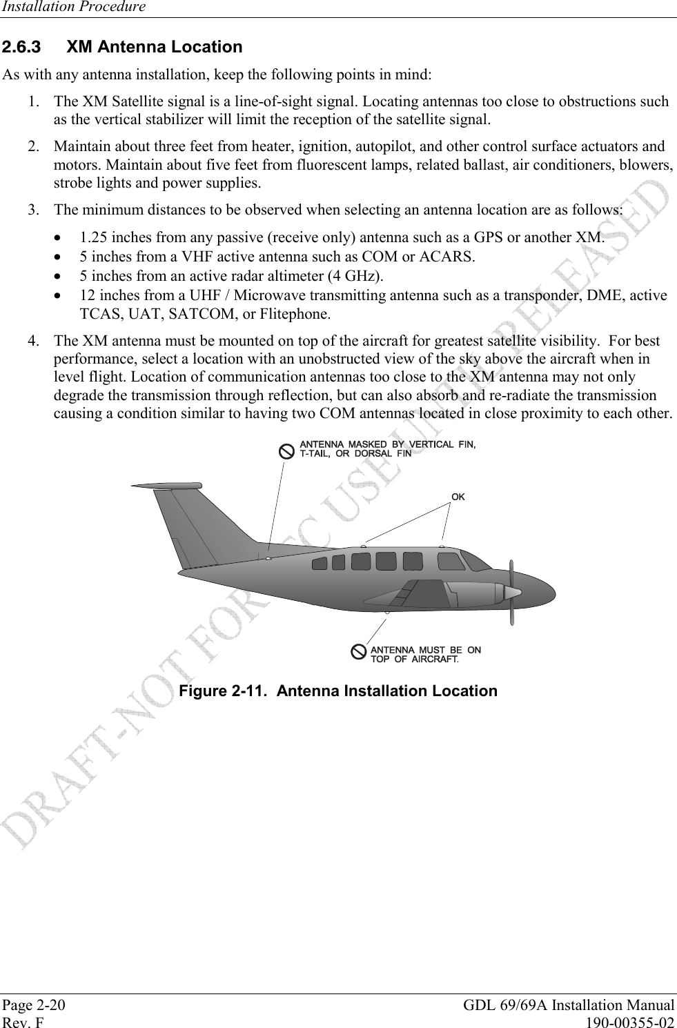
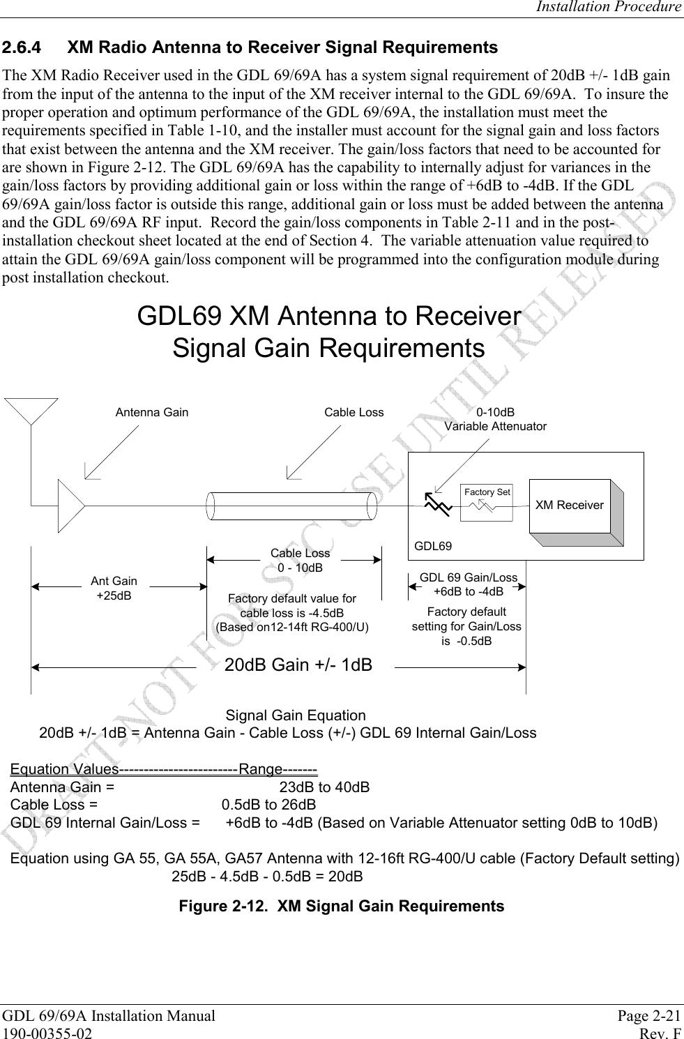
Garmin 01179 Remote Transceiver User Manual 190 00355 02 0F
Garmin International Inc Remote Transceiver 190 00355 02 0F
Garmin >
Contents
- 1. Install Manual Cover and Info
- 2. Install Manual Sect 1
- 3. Install Manual Sect 2
- 4. Install Manual Sect 3 and 4
Install Manual Sect 2
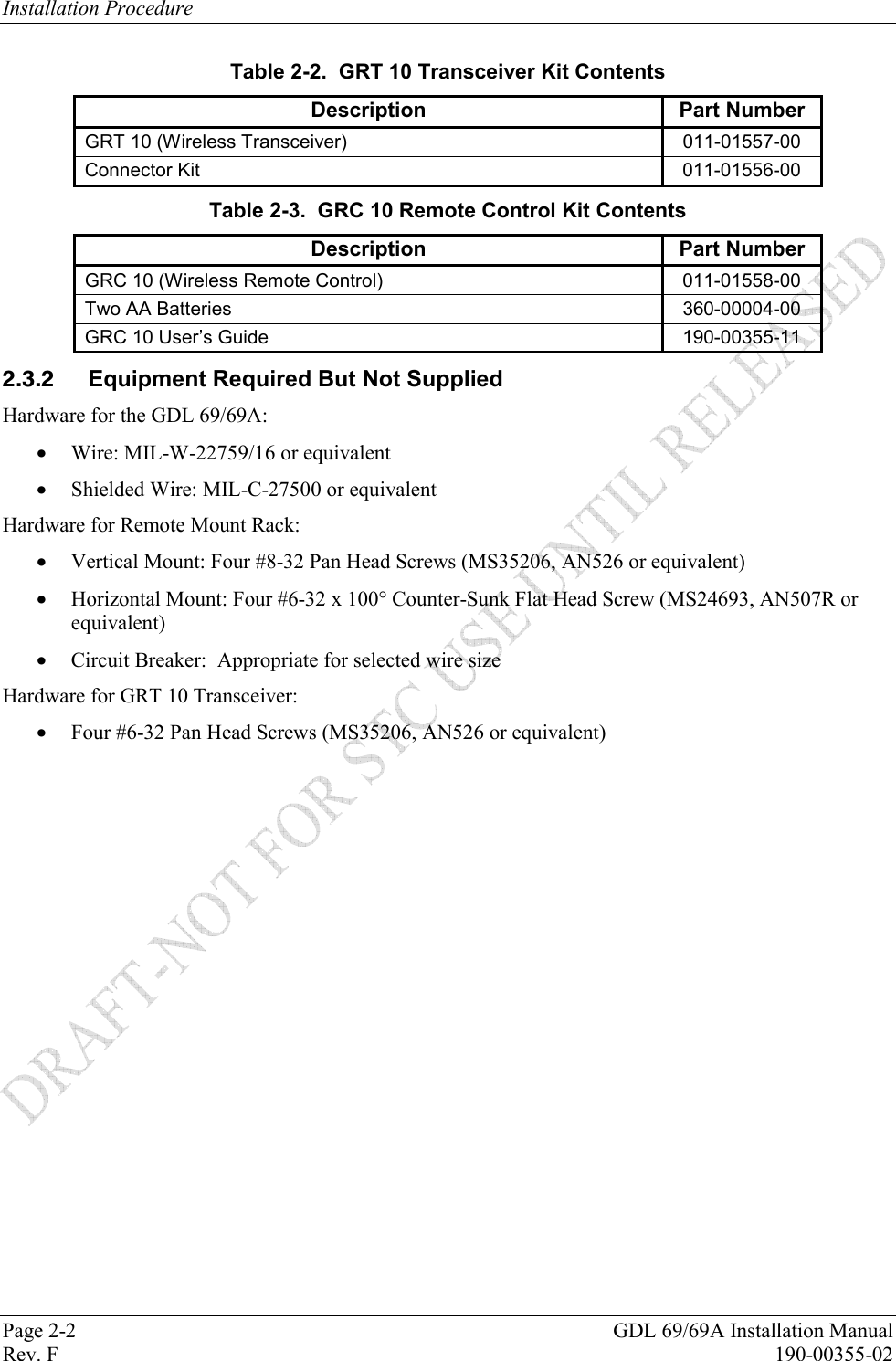
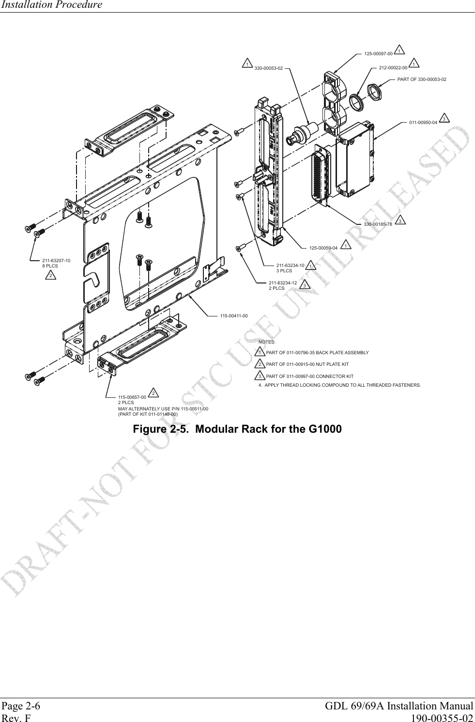
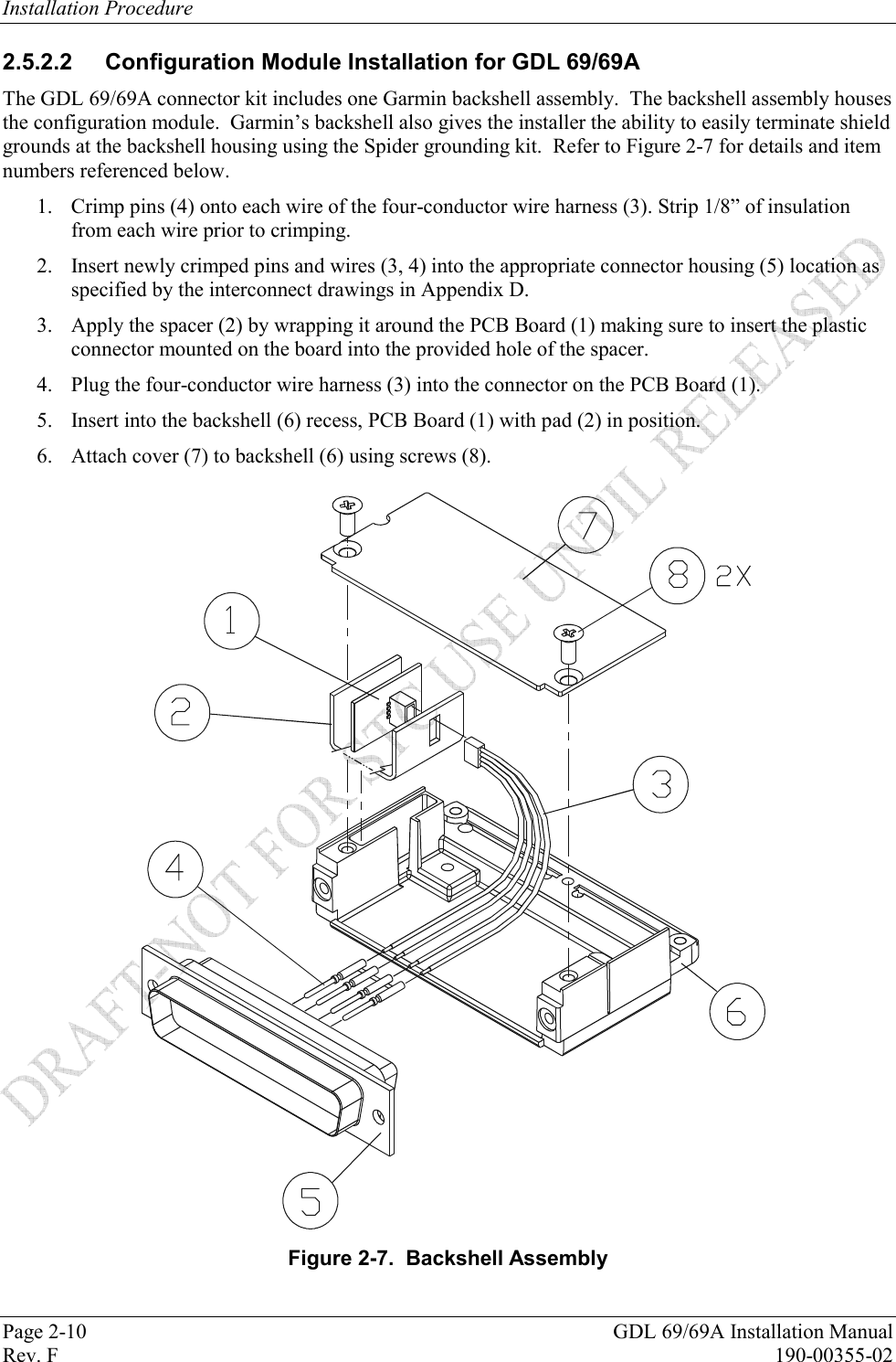
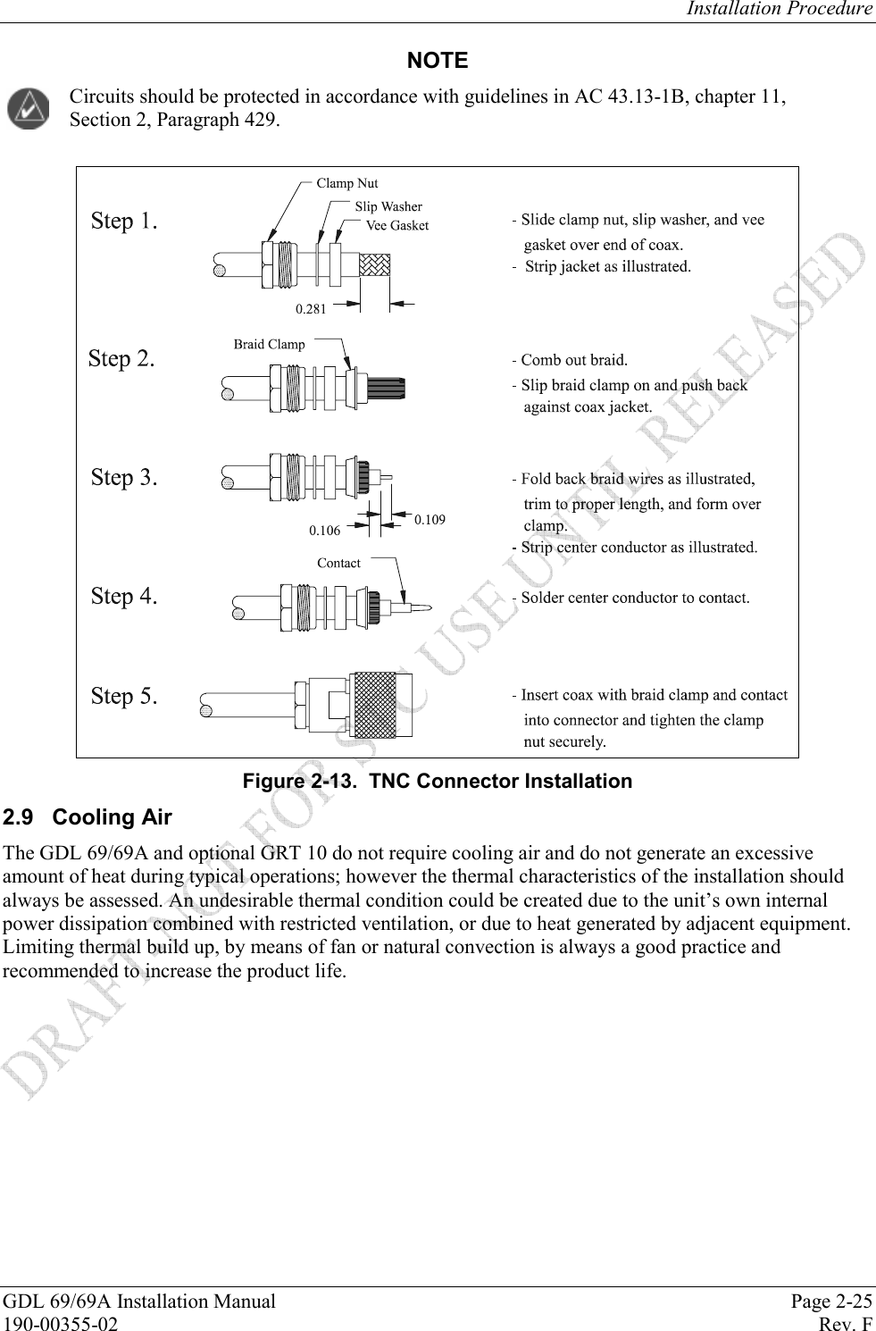
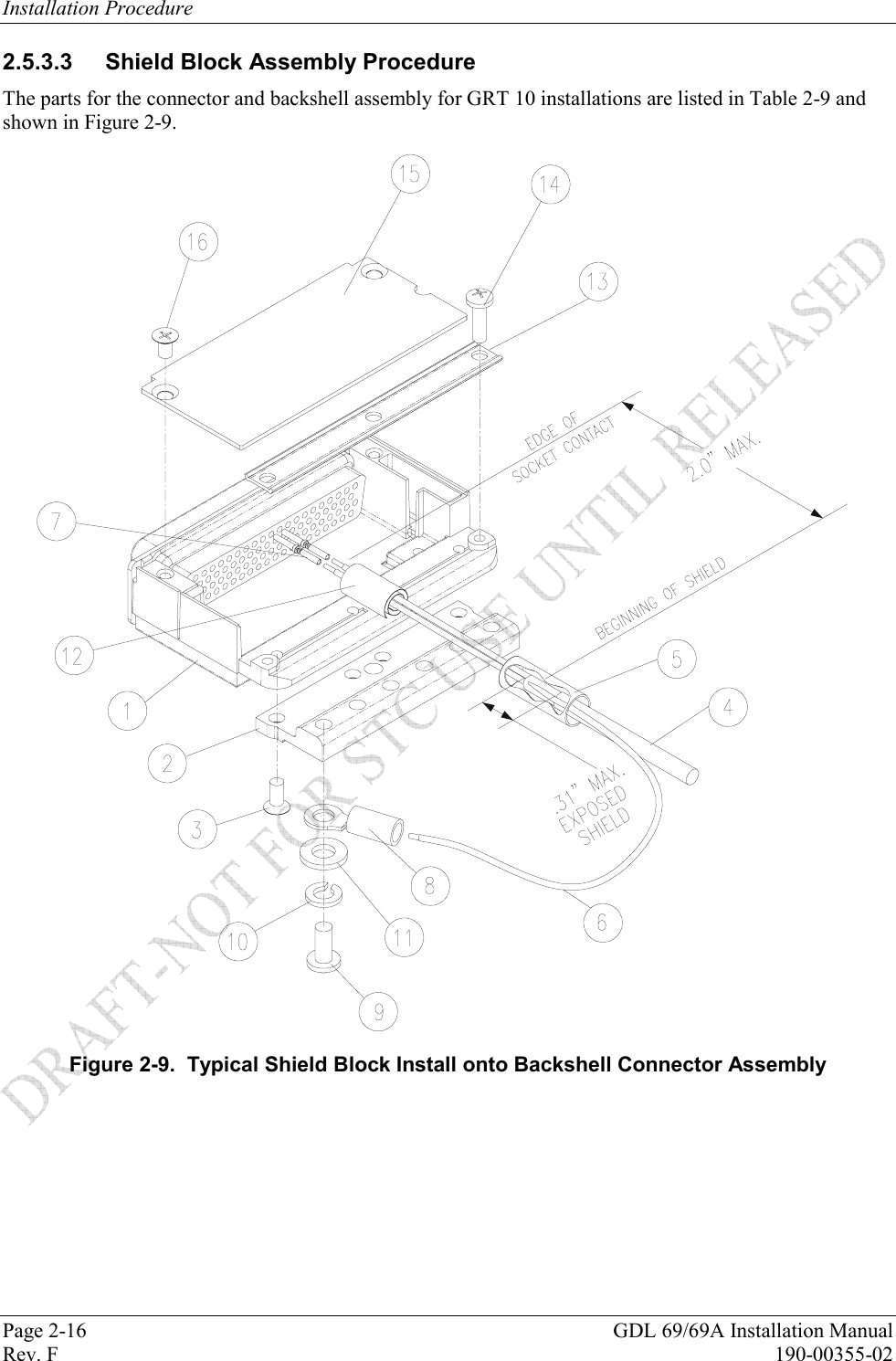
![Installation Procedure Page 2-14 GDL 69/69A Installation Manual Rev. F 190-00355-02 GRT 10 Backshell Assembly and D-sub Connector 2.5.3.1 GRT 10 Connector Assembly 1. Backshell Cast Housing: Provides a mounting point for all other connector accessories. 2. D-sub Connector: Installation details provided in Section 2.4.4. 3. Shield Block Ground Kit: Allows shield grounds to be made to the backshell housing. Installation details provided in Section 2.5.3.3. 4. Strain Relief Tab: Provides strength and support to wiring bundles. 5. Backshell Lid: Provides easy access when servicing connector. Table 2-9. GRT 10 Backshell Assembly Reference Figure 2-9 Description Garmin P/N Notes 1 Cast Housing (From Garmin Backshell Kit) 125-00081-00 [2] 2 Shield block 117-00147-00 [3] 3 Screw, 4-40 x.250, FLHP100, SS/P, Nylon 211-63234-08 [3] 4 Multiple Conductor Shielded Cable (See Interconnect Diagrams, Appendix D As Required [4] 5 Shield Terminator As Required [4], [5] 6 Wire, Insulated (20 – 22 AWG) As Required [4], [5] 7 Socket Contacts 336-00022-00 [1] 8 Ring terminal, #8, insulated, 18-22 AWG, 14-16 AWG MS25036-149, MS25036-153, MS25036-156 [4] 9 Screw, PHP, 8-32x.312", Stainless or Cad Plated Steel MS51957-42, MS35206-242 [4] 10 Split Washer, #8, (.045" compressed thickness) Stainless or Cad-plated steel MS35338-137, MS35338-42 [4] 11 Flat Washer, #8, .032" thick, .174"ID, .375" OD, Stainless or Cad Plated Steel NAS1149CN832R, NAS1149FN832P [4] 12 Silicon Fusion Tape 249-00114-00 [4] 13 Strain Relief 115-00499-00 [2] 14 Screw,4-40x.375, PHP, SS/P, with Nylon 211-60234-10 [2] 15 Cover 115-00500-00 [2] 16 Screw, 4-40x.187, FLHP100, SS/P, with Nylon 211-63234-06 [2] [1] Supplied as part of GRT 10 Connector Kit P/N 011-01556-00. [2] Supplied as part of Backshell Kit P/N 011-00950-00 (included in kit 011-01556-00). [3] Supplied as part of Ground Adapter Kit P/N 011-01169-00 (included in kit 011-01556-00). [4] Not supplied – must be purchased separately. [5] Solder sleeve with pre-installed lead may be used instead of items 5 and 6.](https://usermanual.wiki/Garmin/01179.Install-Manual-Sect-2/User-Guide-905393-Page-14.png)
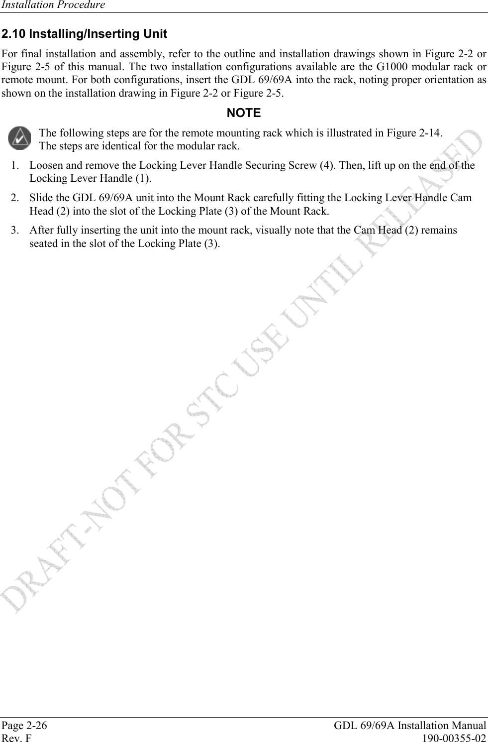
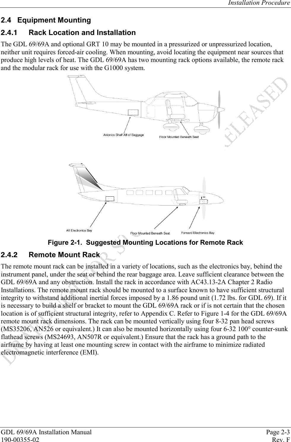
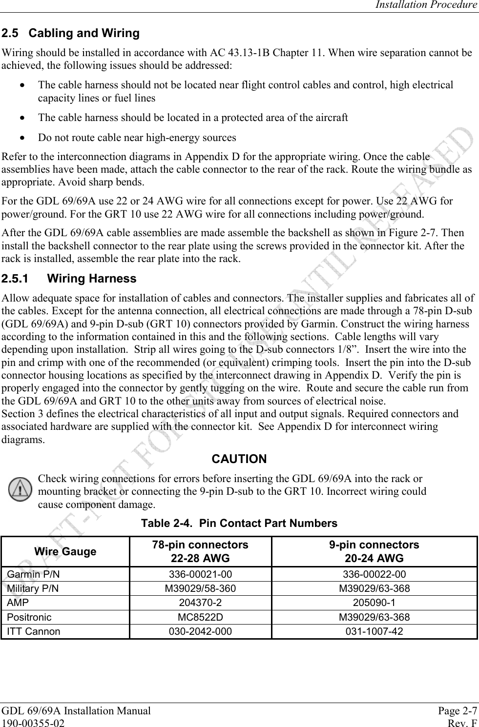
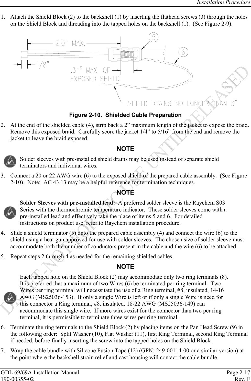
![Installation Procedure GDL 69/69A Installation Manual Page 2-15 190-00355-02 Rev. F 2.5.3.2 D-Sub Connector and Mounting Hardware Table 2-10. D-Sub Connector and Hardware Item Description Garmin P/N Notes 9-Pin Housing (Female) D-Sub, Standard Density, Mil Crimp, 9 ckt 330-00383-09 [1], [2] Spring-loaded Slidelock D-Sub, Slide Lock Kit, 9/15 Pin 330-90006-00 [1] Screw Screw, 4-40 x .375, PHP, SS/P, Nylon 211-60234-10 [1] [1] Supplied as part of the GRT 10 Connector Kit P/N 011-01556-00. [2] Tabless backshell (330-00383-09) is required for use with the slidelock mount CAUTION When mounting the slidelock, use only the specified screws (211-60234-10). Do not attempt to use self-tapping screws, as these damage the backshell housing.](https://usermanual.wiki/Garmin/01179.Install-Manual-Sect-2/User-Guide-905393-Page-15.png)
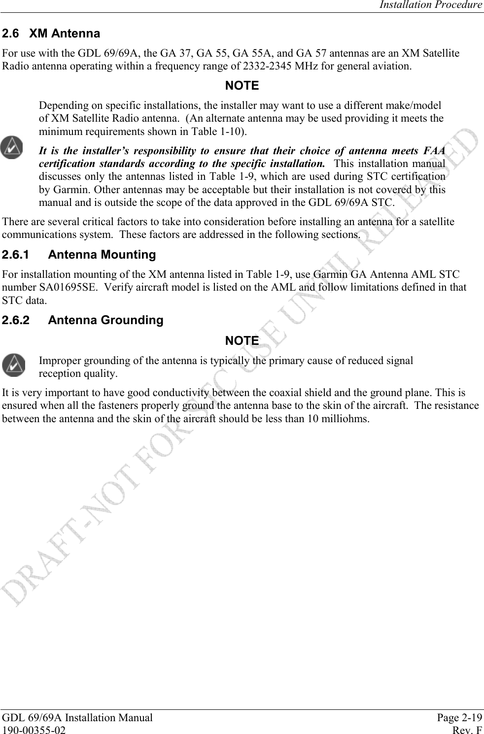
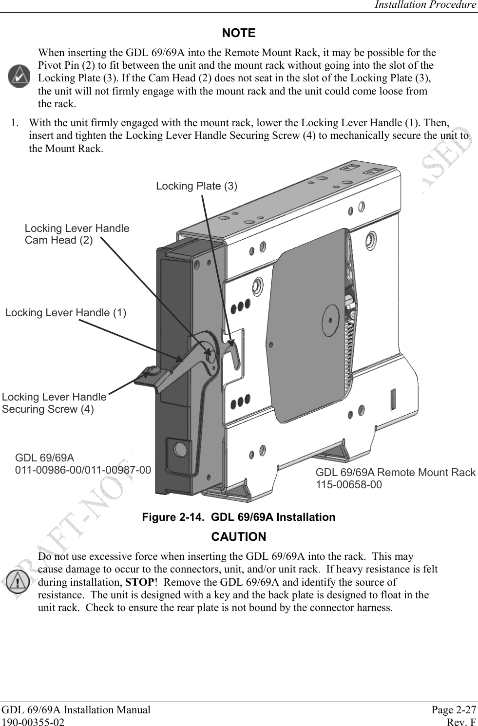
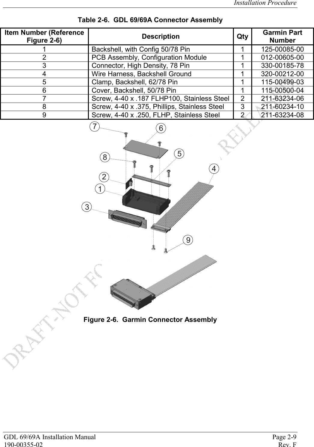
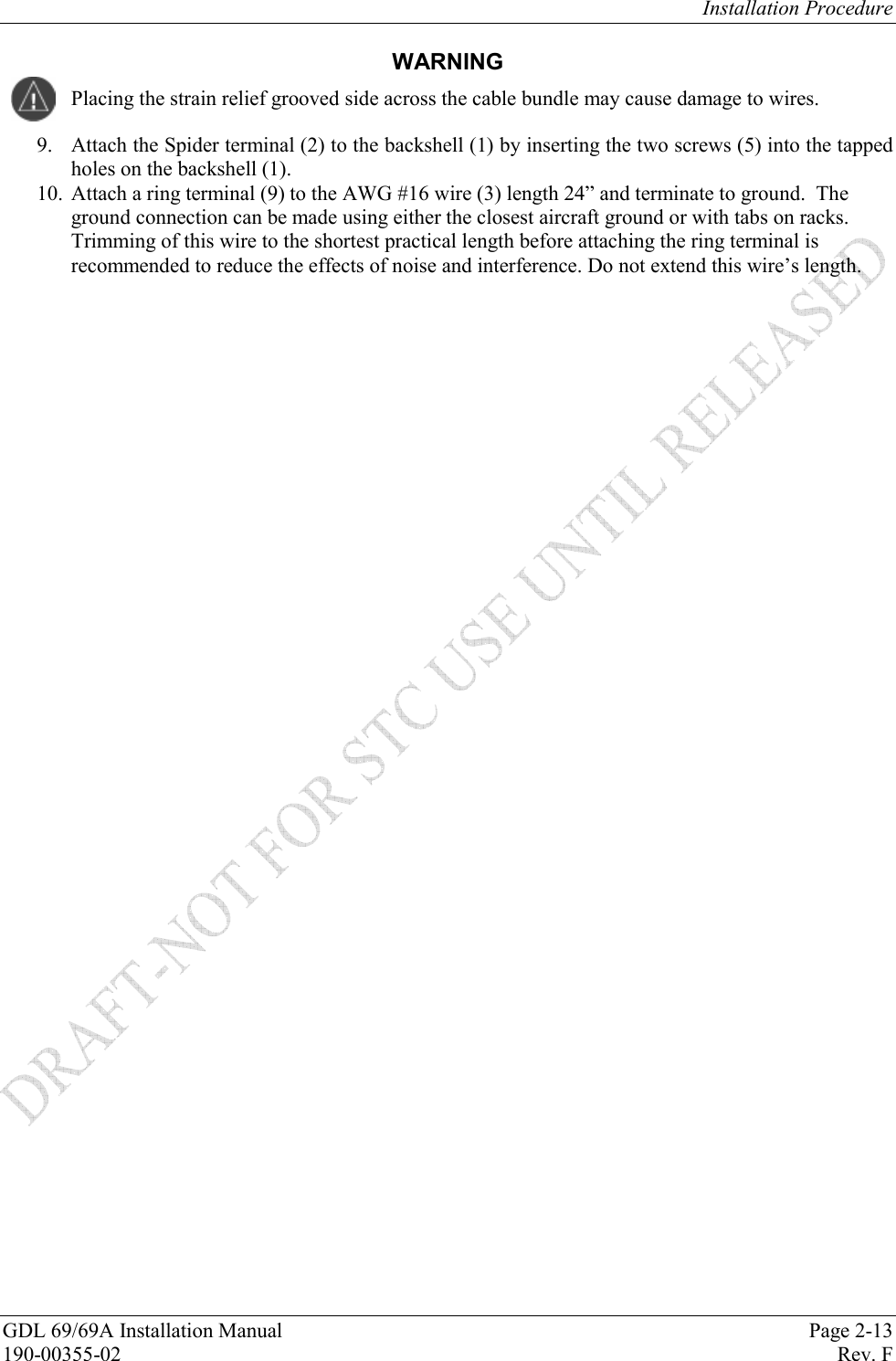
![Installation Procedure Page 2-24 GDL 69/69A Installation Manual Rev. F 190-00355-02 2.7 Weight and Balance Weight and balance computation is required after the installation of the GDL 69/69A and optional GRT 10. Follow the guidelines as established in AC 43.13-1B, Chapter 10, Section 2. Make appropriate entries in the equipment list indicating items added, removed, or relocated along with the date accomplished. Include your name and certificate number in the aircraft records. Table 2-12 identifies the weight of the new GDL 69/69A and optional GRT 10 and GRC 10 equipment. Figure 1-4, Figure 1-5, and Figure 1-6 show the center of gravity. Table 2-12. Unit Weights Item Weight Notes GDL 69 Weight 1.72 lbs (0.78 kg) GDL 69 and Remote Rack Weight 2.69 lbs (1.22 kg) GDL 69 and Modular Rack Weight 2.67 lbs (1.21 kg) GDL 69A Weight 1.86 lbs (0.84 kg) GDL 69A and Remote Rack Weight 2.83 lbs (1.29 kg) GDL 69A and Modular Rack Weight 2.81 lbs (1.27 kg) GA 37 Antenna 0.50 lbs (0.23kg) GA 55 Antenna 0.25 lbs (0.11 kg) GA 55A Antenna 0.43 lbs (0.20 kg) GA 57 Antenna 0.47 lbs (0.21 kg) GRT 10 Transceiver Weight (excluding connector kit) 0.15 lbs (0.07 kg) GRT 10 Transceiver Weight (including connector kit) 0.27 lbs (0.12 kg) GRC 10 Remote Control Weight (without batteries) 0.23 lbs (0.11 kg) [1] GRC 10 Remote Control Weight (with batteries) 0.34 lbs (0.15 kg) [1] [1] The GRC 10 is a portable unit whose weight is negligible and does not need to be included in the weight and balance computation. 2.8 Electrical Load Analysis An electrical load analysis should be completed on each aircraft prior to installation in accordance with AC 43.13-1B, Chapter 11 and recorded on FAA Form 337. Use the following values for computation: GDL 69 Unit Status Max Current @ 28 VDC Max Current @ 14 VDC Off 0.01 A 0.01 A On 0.28 A 0.425 A GDL 69A Unit Status Max Current @ 28 VDC Max Current @ 14 VDC Off 0.01 A 0.01 A On 0.35 A 0.65 A Note: Unit OFF is defined as the unit has power but is turned off with the remote power control signal. GRT 10 Transceiver Unit Status Max Current @ 28 VDC Max Current @ 14 VDC On 36 mA 36 mA GRC 10 Remote Control The GRC 10 Remote Control is a portable battery-powered unit.](https://usermanual.wiki/Garmin/01179.Install-Manual-Sect-2/User-Guide-905393-Page-24.png)