Garmin 01246 LICENSED NON-BROADCAST UAT TRANSMITTER User Manual USERS MANUAL
Garmin International Inc LICENSED NON-BROADCAST UAT TRANSMITTER USERS MANUAL
UserManual.wiki
>
Garmin
>
01246 User Manual
USERS MANUAL
Navigation menu
Upload a User Manual
Namespaces
Wiki Guide
HTML
PDF
Info
Views
User Manual
Discussion / Help
Navigation
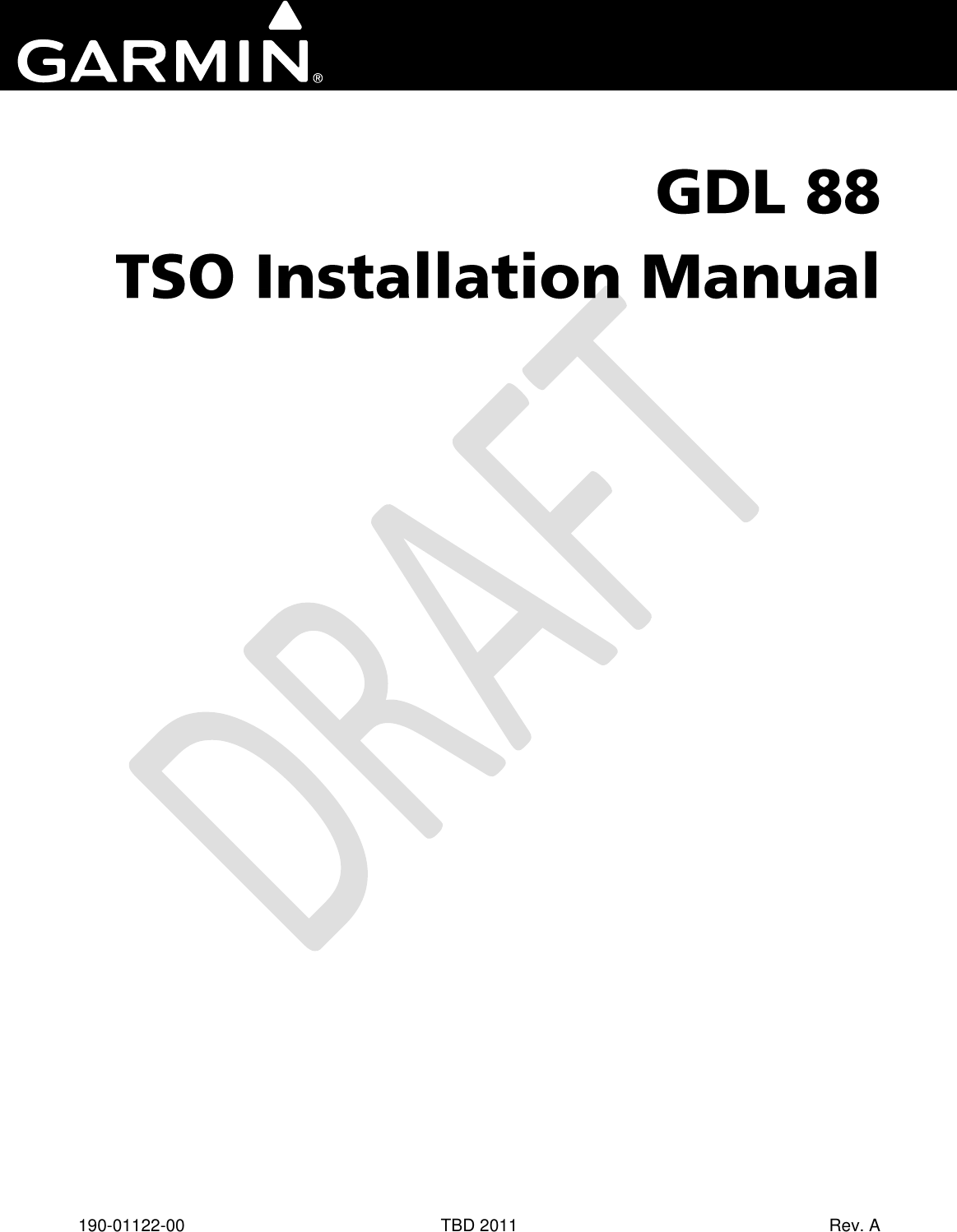
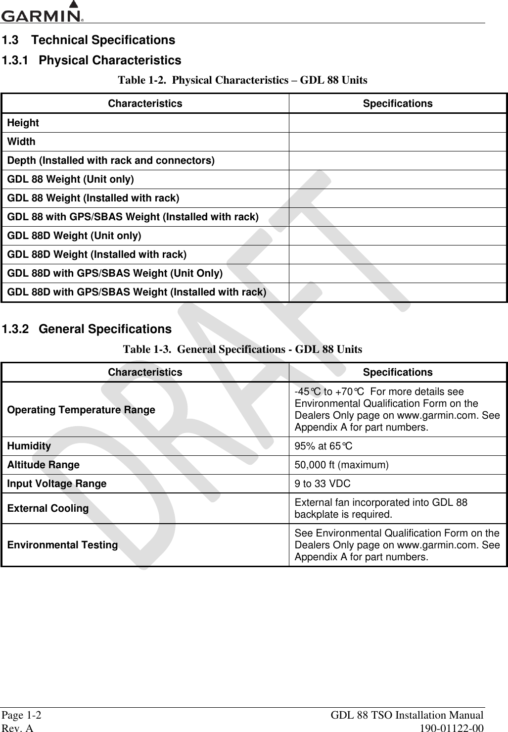
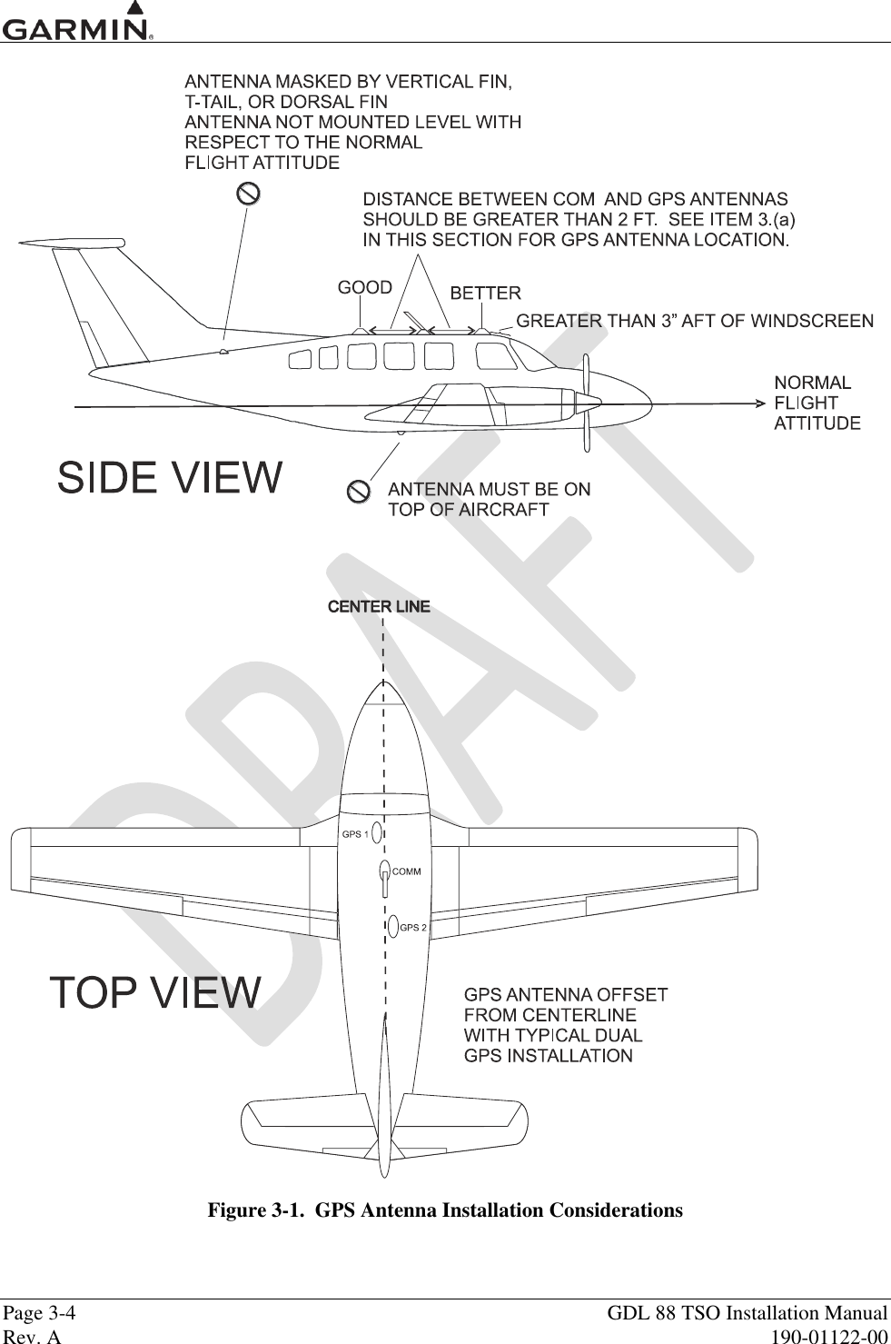
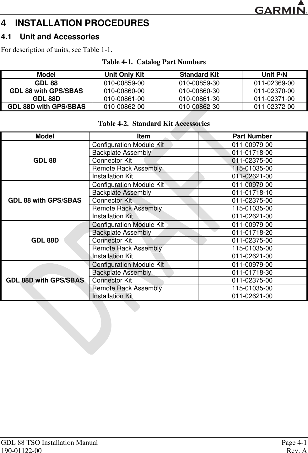
![GDL 88 TSO Installation Manual Page 1-5 190-01122-00 Rev. A 1.3.7 UAT/1090 Requirements The GDL 88 requires UHF antenna(s) meeting the following specifications: Vertically polarized The VSWR produced by the antenna does not exceed 1.7:1 at 978 MHz and 1.5:1 at 1090 MHz. TSO-C66, TSO-C74, or TSO-C112 antennas that also meet the VSWR specification. NOTE Certain types of transponder antennas that utilize very thin radiator elements are only intended for use at 1030 and 1090 MHz. These types of antennas should be evaluated on a model-by-model basis to determine their suitability as UAT data link antennas. CAUTION Operating the GDL 88 without RF terminations on the top or bottom UAT antenna ports can result in equipment damage. Always operate the GDL 88 with the top and bottom UAT antenna ports terminated with a VSWR ration of 3.0:1 or less. 1.3.8 GPS Antenna Requirements Antenna performance is critical to the GPS/SBAS operation. The antennas listed in Table 1-8 provide acceptable performance with the GDL 88. Table 1-8. Approved GPS/SBAS Antennas Model/Description Conn Type Mfr Part Number Garmin Order Number GA 35, GPS/WAAS [1] TNC Garmin 013-00235-( ) 013-00235-( ) Aero Antenna AT575-93G( )-TNCF-000-RG-27-NM GA 36, GPS/WAAS TNC Garmin 013-00244-( ) 013-00244-( ) Aero Antenna AT575-126G( )-TNCF-000-RG-27-NM GA 37, GPS/WAAS/XM TNC Garmin 013-00245-( ) 013-00245-( ) Aero Antenna AT2300-126G( )-TNCF-000-RG-27-NM A33W, WAAS Antenna TNC Garmin 013-00261-( ) 013-00261-( ) Aero Antenna AT575-332G( )- TNCF-000-RG-27-NM GPS/VHF Antenna TNC/BNC [2] Comant CI-2580-200 N/A GPS/VHF Antenna TNC/BNC [2] Comant CI-2728-200 N/A GPS/XM/VHF Antenna TNC/TNC/BNC [3] Comant CI-2580-410 N/A GPS/XM/VHF Antenna TNC/TNC/BNC [3] Comant CI-2728-410 N/A GPS/WAAS Antenna TNC Comant CI-428-200 N/A GPS/XM Antenna TNC/TNC Comant CI-428-410 N/A [1] Same mounting hole pattern as GA 56, but GA 35 antenna has a physically larger footprint. [2] The antenna connector is a TNC type. The VHF connector is a BNC type. [3] The antenna connector is a TNC type. The XM connector is a TNC type. The VHF connector is a BNC type.](https://usermanual.wiki/Garmin/01246/User-Guide-1692338-Page-13.png)
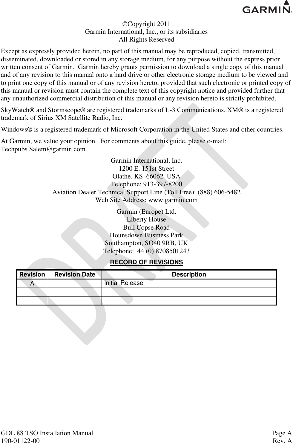
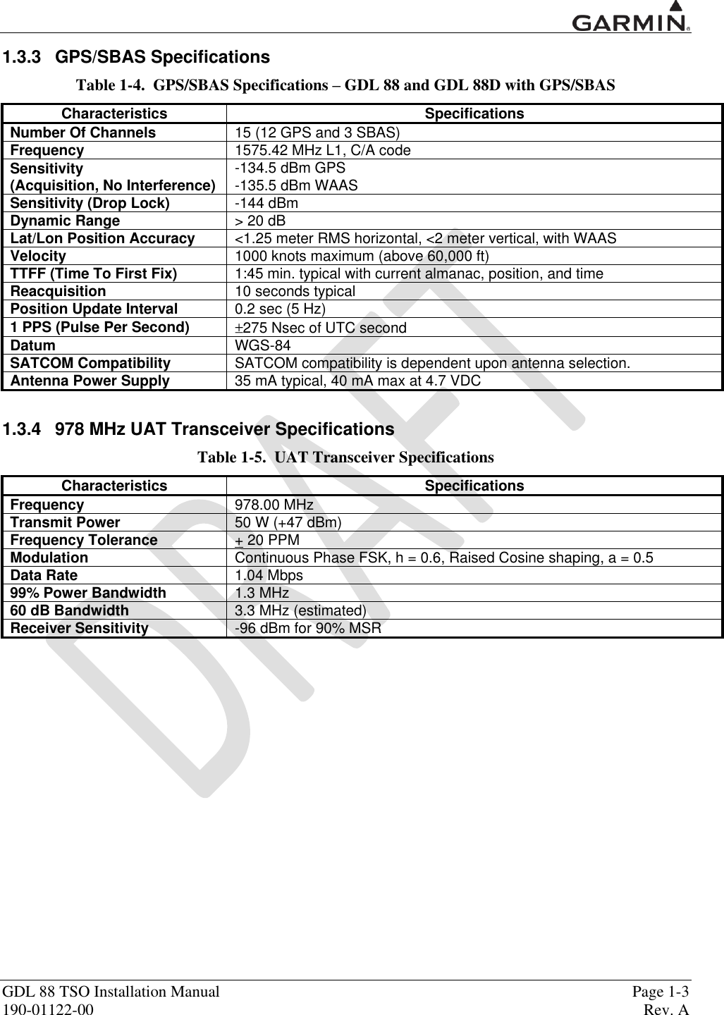
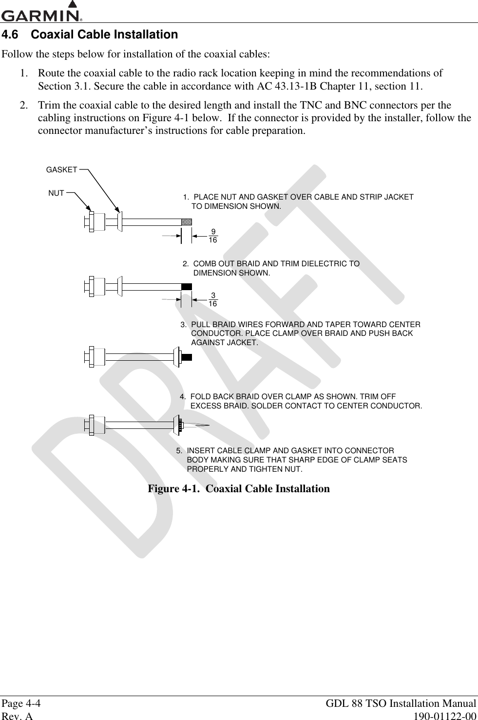
![Page 4-2 GDL 88 TSO Installation Manual Rev. A 190-01122-00 4.2 Optional Accessories 4.2.1 GPS Antenna Options For details regarding antenna selection, refer to Section 1.3.8. Once the antenna type is decided upon, refer to the information below for detailed parts information for antennas available directly from Garmin. Contact the manufacturer directly for information on other antennas. GA 35 Antenna: GA 35 Antenna Garmin P/N 013-00235-00 contains the following items: Item Part Number Qty GA 35 GPS/ WAAS Antenna [1] 013-00235-00 (Garmin) 1 AT575-93G (Aero Antenna) [1] Antenna includes 8-32 UNC-2A x 1.00” SS 303 mounting screws (qty 4) and O-ring (qty 1). An antenna doubler may also be required. Refer to the appropriate antenna installation data. To secure the antenna #8 washers (qty 4) and #8 (qty 4) self-locking nuts are required in addition to the antenna, or suitable nutplates may be installed on the doubler. To connect the GPS antenna coaxial cable to the antenna a TNC plug is required. GA 36 Antenna: GA 36 Antenna Garmin P/N 013-00244-00 contains the following items: Item Part Number Qty GA 36 GPS/WAAS Antenna [1] 013-00244-00 (Garmin) 1 AT575-126G (Aero Antenna) [1] Antenna includes 8-32 UNC-2A x 1.00” SS 303 mounting screws (qty 4) and O-ring (qty 1). An antenna doubler may also be required. Refer to the appropriate antenna installation data. To secure the antenna #8 washers (qty 4) and #8 (qty 4) self-locking nuts are required in addition to the antenna, or suitable nutplates may be installed on the doubler. To connect the GPS antenna coaxial cable to the antenna a TNC plug is required. GA 37 Antenna: GA 37 Antenna Garmin P/N 013-00245-00 contains the following items: Item Part Number Qty GA 37 GPS/WAAS + XM Antenna [1] 013-00245-00 (Garmin) 1 AT2300-126G (Aero Antenna) [1] Antenna includes 8-32 UNC-2A x 1.00” SS 303 mounting screws (qty 4) and O-ring (qty 1). An antenna doubler may also be required. Refer to the appropriate antenna installation data. To secure the antenna #8 washers (qty 4) and #8 (qty 4) self-locking nuts are required in addition to the antenna, or suitable nutplates may be installed on the doubler. To connect the GPS antenna coaxial cable to the antenna a TNC plug is required. A33W Antenna: A33W Antenna Garmin P/N 013-00261-00 contains the following items: Item Part Number Qty A33W, WAAS [1] 013-00261-00 (Garmin) 1 [1] Antenna includes 6-32 UNC-2A x 1.00” SS 303 mounting screws (qty 4) and O-ring (qty 1). An antenna doubler may also be required. To secure the antenna, #6 washers (qty 4) and #6 (qty 4) self-locking nuts are required in addition to the antenna, or suitable nutplates may be installed on the doubler that is used. To connect the GPS antenna coaxial cable to the antenna a TNC plug is required.](https://usermanual.wiki/Garmin/01246/User-Guide-1692338-Page-24.png)
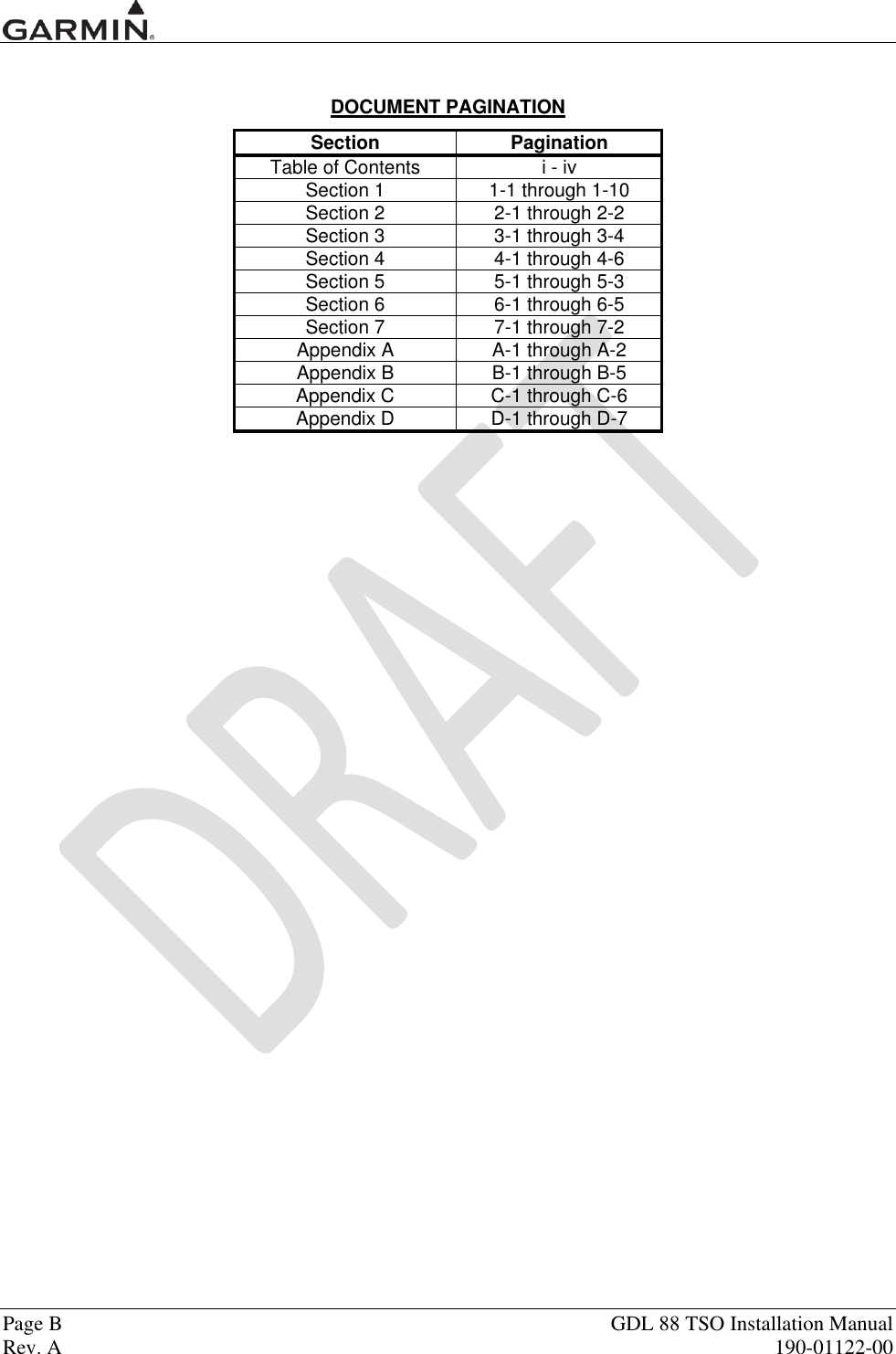
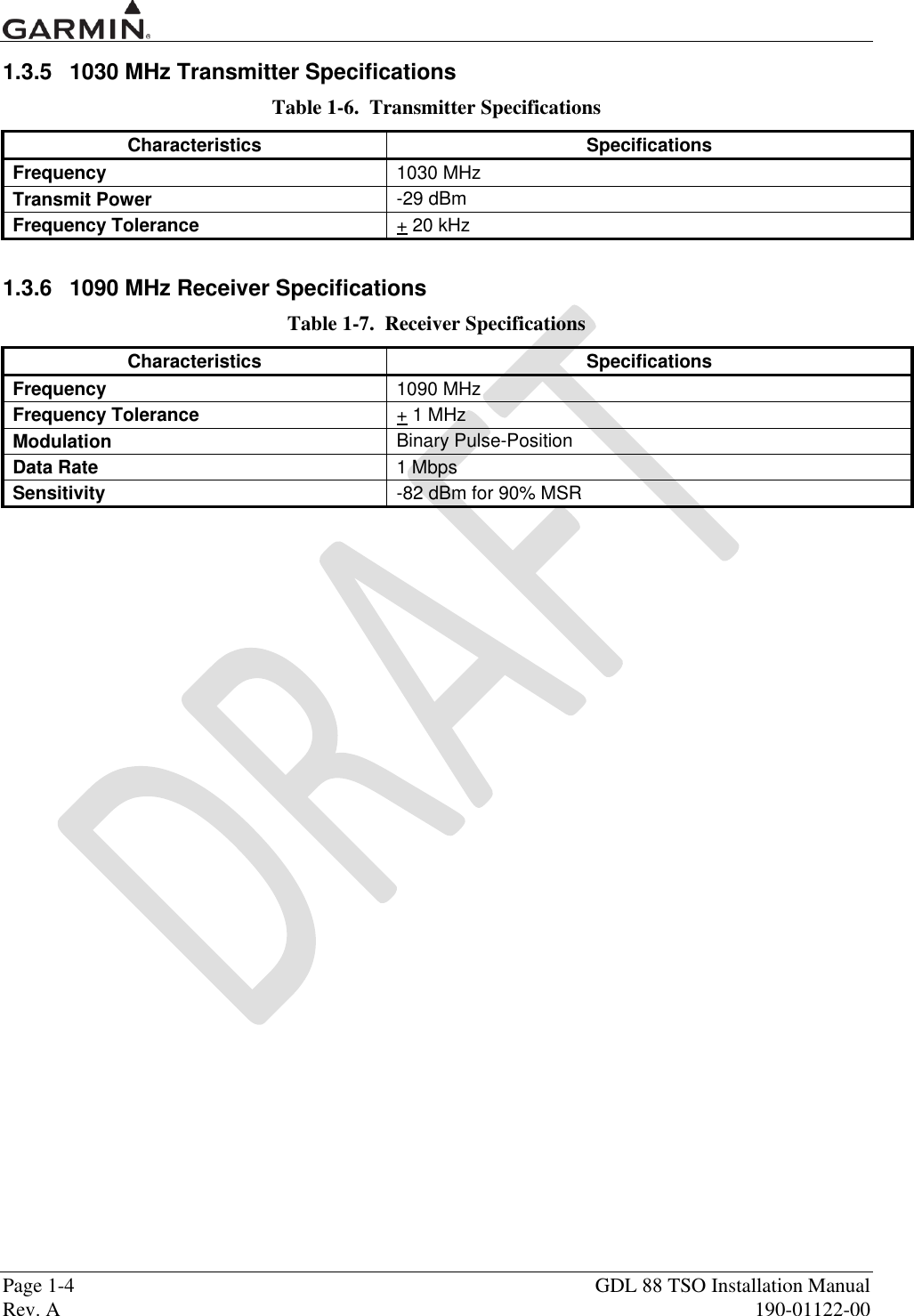
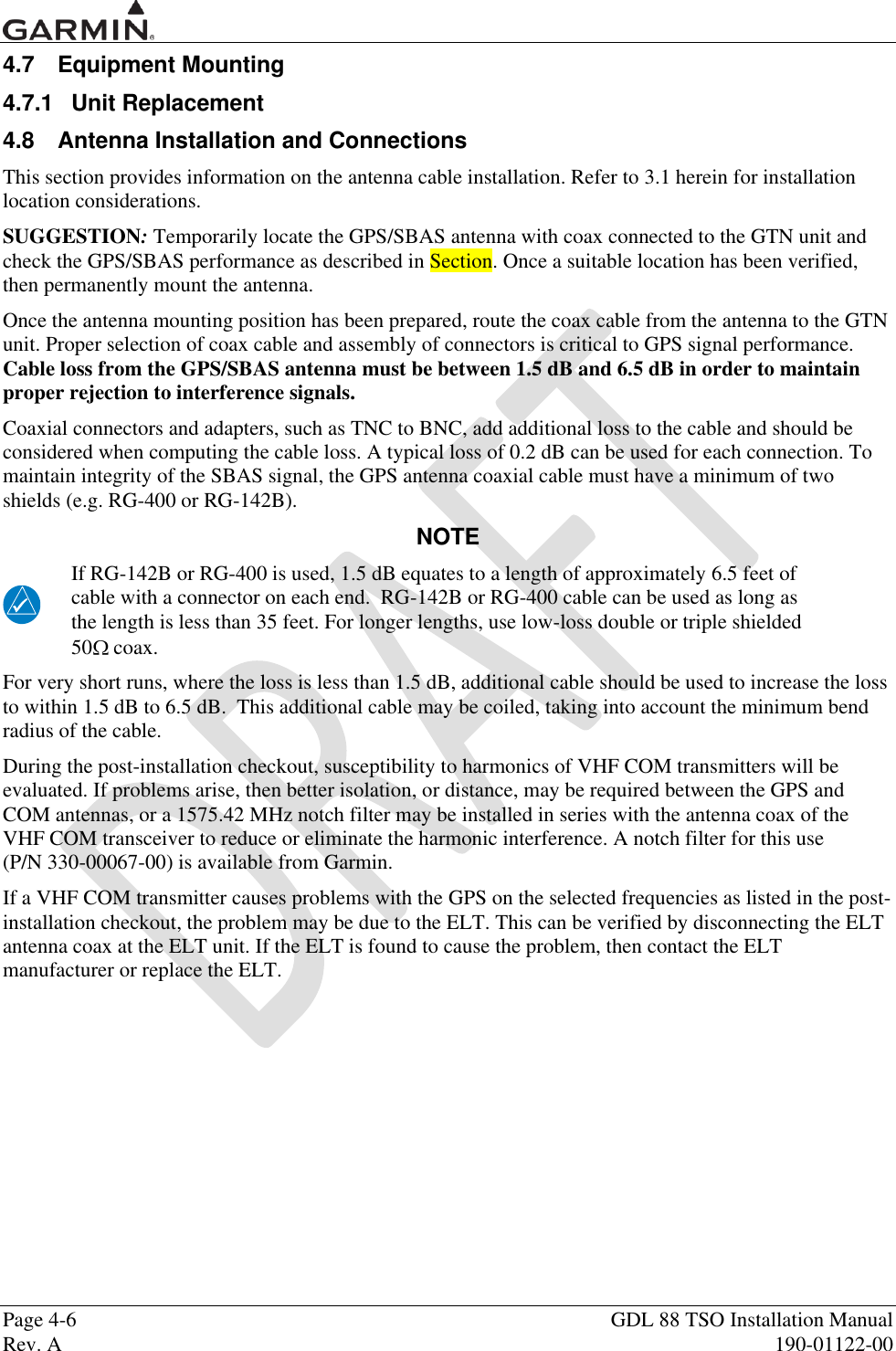
![GDL 88 TSO Installation Manual Page 4-3 190-01122-00 Rev. A 4.2.2 UAT Antenna Options 4.3 Miscellaneous Options Item Garmin P/N Mfg P/N Connector, BNC, Male, Clamp 330-00087-00 N/A GPS 1.57542 GHz Notch Filter 330-00067-00 N/A Connector, TNC, Male, Clamp N/A 031-4452 [1] [1] This part is not available from Garmin. Vendor Contact Information (provided for convenience only): Amphenol RF, Four Old Newtown Road, Danbury, CT 06810 Phone: 800-627-7100 4.4 Installation Materials not Supplied 4.4.1 Installation Materials Required but not Supplied The GDL 88 is intended for use with the standard aviation accessories. The following items are required for installation, but not supplied. Wire (MIL-W-22759/16 or equivalent) Shielded Wire (MIL-C-27500 or equivalent) Mounting Screws (8 minimum – MS24693 Screw, Machine, Flat Countersunk Head 100°, Cross-recessed with .1380-32 UNC-2A Thread, Corrosion Resistant Steel) Push/Pull (manually resettable) Circuit Breakers Tie Wraps or Lacing Cord Ring Terminals (for grounding) Coaxial Cable (RG-400, RG-142B or equivalent – Refer to Section 4.11 for additional information). 4.5 Special Tools Required Some of the connectors use crimp contacts. The table below identifies crimp tools required to ensure consistent, reliable crimp contact connections for the rear D-sub connectors. Table 4-3. Recommended Crimp Tools (or Equivalent) Manufacturer Hand Crimping Tool 22 – 28 AWG (P1001 – P1005) Positioner Insertion/ Extraction Tool Military P/N M22520/2-01 M22520/2-09 M81969/14-01 M81969/1-04 Positronic 9507-0-0-0 9502-4-0-0 M81969/1-04 ITT Cannon 995-0001-584 995-0001-739 000849490 274-7048-000MIL AMP 601966-1 601966-6 91067-1 2031838-1 Daniels AFM8 K42 M81969/14-01 M81969/1-04 Astro 615717 615725 M81969/14-01 M81969/1-04 NOTE Insertion/extraction tools from ITT Cannon are all plastic; others are plastic with metal tip.](https://usermanual.wiki/Garmin/01246/User-Guide-1692338-Page-25.png)
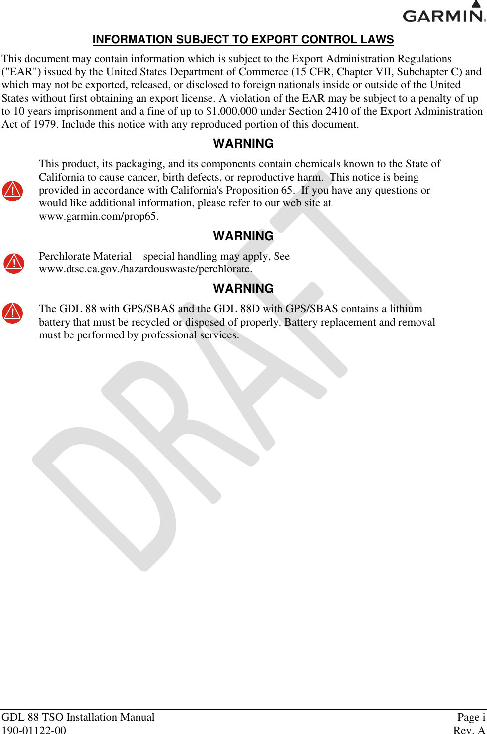
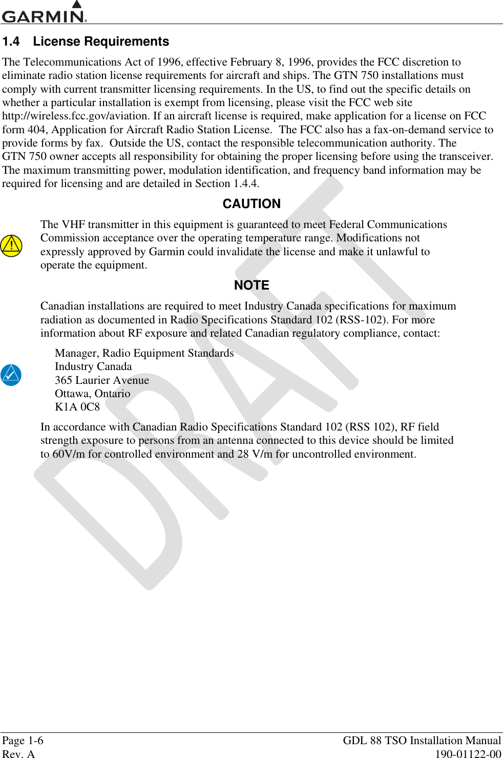
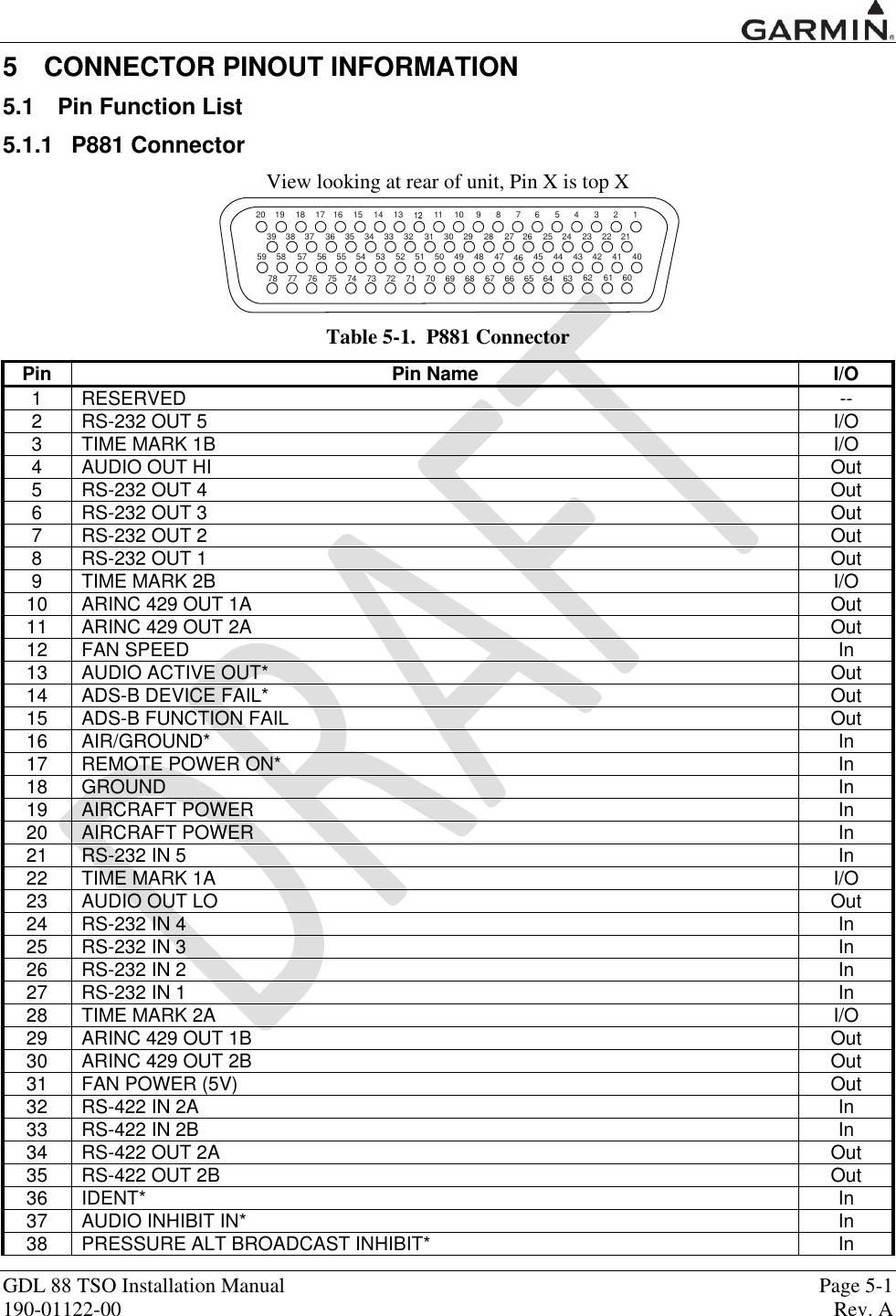
![GDL 88 TSO Installation Manual Page 4-5 190-01122-00 Rev. A Table 4-4. Socket Contact Part Numbers Wire Gauge Configuration Module 78-pin Connector (P1001) P1001-P1005 28 AWG [1] 22-28 AWG [2] Garmin P/N 336-00021-00 336-00021-00 Military P/N N/A M39029/58-360 AMP N/A 204370-2 Positronic N/A MC8522D ITT Cannon N/A 010-2042-000 [1] For configuration module pins, ensure that the crimp tool is set to crimp 28 AWG wire (indenter setting of „4‟). [2] Contacts listed are not to be used for configuration module wiring. Use the contacts supplied with the configuration module when installing configuration module wires in P1001. [3] Non-Garmin part numbers shown are not maintained by Garmin and are subject to change without notice.](https://usermanual.wiki/Garmin/01246/User-Guide-1692338-Page-27.png)

![Page B-2 GDL 88 TSO Installation Manual Rev. A 190-01122-00 Appendix B GDL 88 DATA FORMAT B.1 GDL 88 RS-232 Fuel/Air Data Input Format B.1.1 Electrical Interface The input signals are compatible with RS-232C. Data input at 9600 baud (1200 baud for Apollo Altitude Encoder) with a word length of 8 bits, one stop bit, and no parity. One message is received per second. B.1.2 Icarus Altitude Sentence The GDL 88 is capable of receiving the following 10-byte message from the Icarus Altitude Serializer: ALT <sp>12345<CR> Where: ALT ASCII characters <sp> space (0x20) 12345 altitude in feet <CR> carriage return (0x0d) B.1.3 Apollo Altitude Sentence The GDL 88 is capable of receiving the following 17-byte message from an Apollo Altitude Encoder: #AL<sp><+/->ddul<CR> Where: #AL ASCII characters <sp> space (0x20) <+/-> sign indicator (0x2B[“+”] or 0x2D[“-“]) ddddd altitude in feet (-1000 feet to 35,000 feet) T ASCII characters <+/-> sign indicator dd sensor temperature ul checksum of bytes 1 through 14 in hex ASCII (i.e. “FA”) <CR> carriage return (0x0D)](https://usermanual.wiki/Garmin/01246/User-Guide-1692338-Page-38.png)
![GDL 88 TSO Installation Manual Page B-3 190-01122-00 Rev. A B.1.4 Shadin Altitude Sentence The GDL 88 is capable of receiving the following 17-byte message from Shadin Altitude Encoders, Altitude Serializers, and Altitude Converters: RMS<sp><+/->12345T<+/->12ul<CR> Where: RMS ASCII characters <sp> space (0x20) <+/-> sign indicator (0x2b["+"] or 0x2d["-"]) 12345 altitude in feet T ASCII character <+/-> sign indicator 12 sensor temperature ul checksum of bytes 1 through 14 in hex ASCII (i.e., "FA") <CR> carriage return (0x0d) Note: Checksum is calculated by adding each byte in the message (1 through 14).](https://usermanual.wiki/Garmin/01246/User-Guide-1692338-Page-39.png)
![Page B-4 GDL 88 TSO Installation Manual Rev. A 190-01122-00 B.1.5 Shadin Fuel/Air Data Computer The GDL 88 is capable of receiving the following message strings from the Shadin Fuel/Air Data or Air Data Computer: SHADIN “z” FORMAT <STX> ZA012<CR><LF> "ZA" (ASCII characters); "012" represents indicated Air Speed (knots) ZB345<CR><LF> "ZB" (ASCII characters); "345" represents true Air Speed (knots) ZC678<CR><LF> "ZC" (ASCII characters); "678" represents Mach Speed (thousandths) ZD<+/->9012<CR><LF> "ZD" (ASCII characters); sign; "9012" represents pressure altitude (tens of feet) ZE<+/->3456<CR><LF> "ZE" (ASCII characters); sign; "3456" represents density altitude (tens of feet) ZF<+/->78<CR><LF> "ZF" (ASCII characters); sign; "78" represents outside air temperature (Celsius) ZG<+/->90<CR><LF> "ZG" (ASCII characters); sign; "90" represents true air temperature (Celsius) ZH123<CR><LF> "ZH" (ASCII characters); "123" represents wind direction (degrees from north) ZI456<CR><LF> "ZI" (ASCII characters); "456" represents wind speed (knots) ZJ<+/->78<CR><LF> "ZJ" (ASCII characters); sign; "78" represents rate of turn (degrees per second) ZK<+/->901<CR><LF> "ZK" (ASCII characters); sign; "901" represents vertical speed (tens of ft/minute) ZL234<CR><LF> "ZL" (ASCII characters); "234" represents heading (degrees from north) ZM5678<CR><LF>† "ZM" (ASCII characters); "5678" represents fuel flow, right (tenths gallons/hour) ZN90123<CR><LF>† "ZN" (ASCII characters); "90123" represents fuel used, right (tenths gallons) ZO4567<CR><LF>† "ZO" (ASCII characters); "4567" represents fuel flow, left (tenths gallons/hour) ZP89012<CR><LF>† "ZP" (ASCII characters); "89012" represents fuel used, left (tenths gallons) ZQ345<CR><LF> "ZQ" (ASCII characters); "345" represents error log/reason indicator ZR678<CR><LF> "ZR" (ASCII characters); "678" represents checksum <ETX> Where: <STX> start-transmit character (0x02) <CR> carriage-return character (0x0d) <LF> line-feed character (0x0a) <+/-> sign indicator (0x2b["+"] or 0x2d["-"]) <ETX> end-transmit character (0x03) † Not available from Air Data Computer Note: Checksum is calculated by adding each byte in the message (including all characters from <STX> up to and including the error log/reason indicator), such that carries are discarded to give a one byte result. The ASCII-coded decimal representation of that byte is given, ranging from 0 (0x30, 0x30, 0x30) to 255 (0x32, 0x35, 0x35).](https://usermanual.wiki/Garmin/01246/User-Guide-1692338-Page-40.png)