Garmin 01594 AIRBORNE COMMUNICATIONS TRANSCEIVER User Manual 190 01007 02 0A
Garmin International Inc AIRBORNE COMMUNICATIONS TRANSCEIVER 190 01007 02 0A
UserManual.wiki
>
Garmin
>
01594 User Manual
Users Manual
Navigation menu
Upload a User Manual
Namespaces
Wiki Guide
HTML
PDF
Info
Views
User Manual
Discussion / Help
Navigation

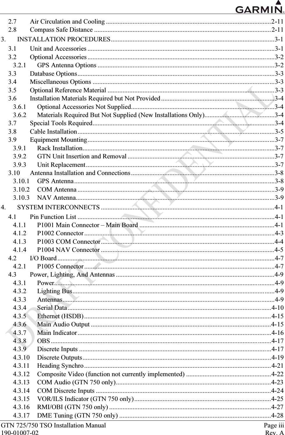
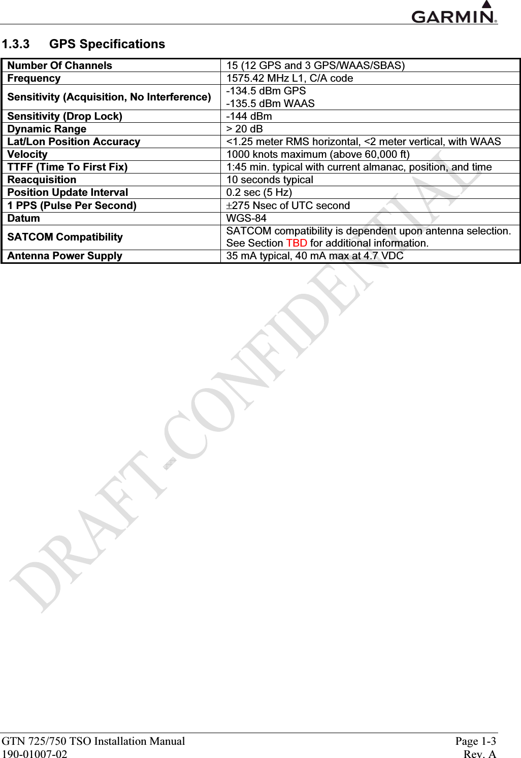
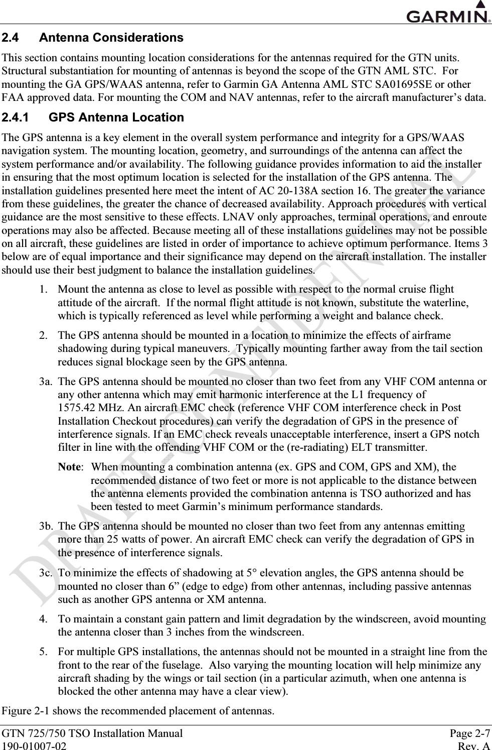
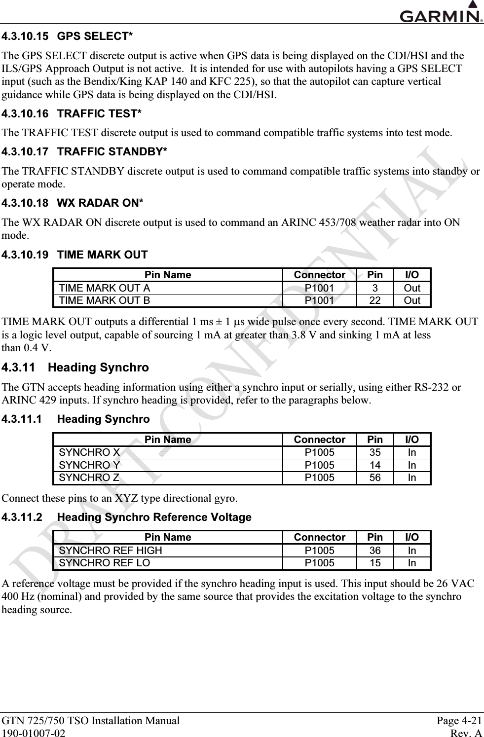
![GTN 725/750 TSO Installation Manual Page 1-7 190-01007-02 Rev. A 1.3.8 GPS Antenna Requirements Antenna performance is critical to the GPS/WAAS operation. The antennas listed in Table 1-3 are approved for installation with the GTNs. Table 1-3. Approved GPS Antennas Model/Description Conn Type Mfr Part Number Garmin Order Number Garmin 013-00235-( ) GA 35, GPS/WAAS [1] TNC Aero Antenna AT575-93G( )-TNCF-000-RG-27-NM 013-00235-( ) Garmin 013-00244-( ) GA 36, GPS/WAAS TNC Aero Antenna AT575-126G( )-TNCF-000-RG-27-NM 013-00244-( ) Garmin 013-00245-( ) GA 37, GPS/WAAS/XM TNC Aero Antenna AT2300-126G( )-TNCF-000-RG-27-NM 013-00245-( ) Garmin 013-00261-( ) A33W, WAAS Antenna [3] TNC Aero Antenna AT575-332G( )- TNCF-000-RG-27-NM 013-00261-( ) GPS/VHF Antenna TNC/BNC [2] Comant [3] CI-2580-200 N/A GPS/VHF Antenna TNC/BNC [2] Comant [3] CI-2728-200 N/A GPS/XM/VHF Antenna TNC/TNC/BNC [4] Comant [3] CI-2580-410 N/A GPS/XM/VHF Antenna TNC/TNC/BNC [4] Comant [3] CI-2728-410 N/A GPS Antenna TNC Comant [3] CI-428-200 N/A GPS/XM Antenna TNC/TNC Comant [3] CI-428-410 N/A [1] Same mounting hole pattern as GA 56, but GA 35 antenna has a physically larger footprint. [2] The GPS/WAAS connector is a TNC type. The VHF connector is a BNC type. [3] Installation of this antenna is not covered by the Garmin GA Antenna AML STC SA01695SE. [4] The GPS/WAAS connector is a TNC type. The XM connector is a TNC type. The VHF connector is a BNC type.](https://usermanual.wiki/Garmin/01594/User-Guide-1434717-Page-19.png)

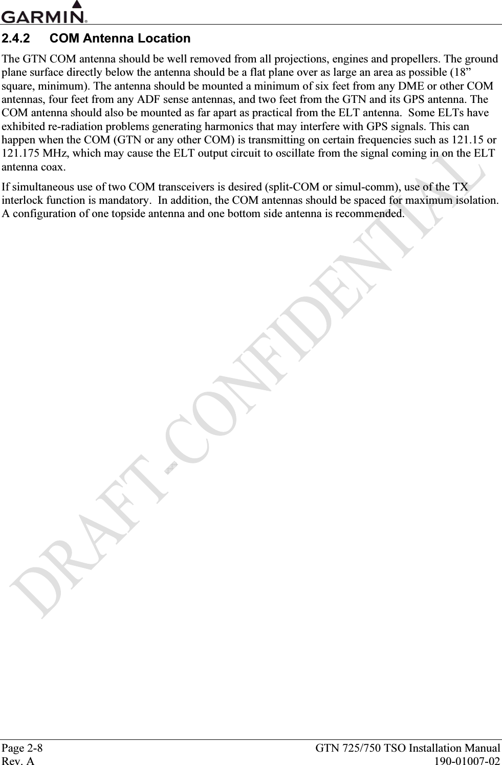

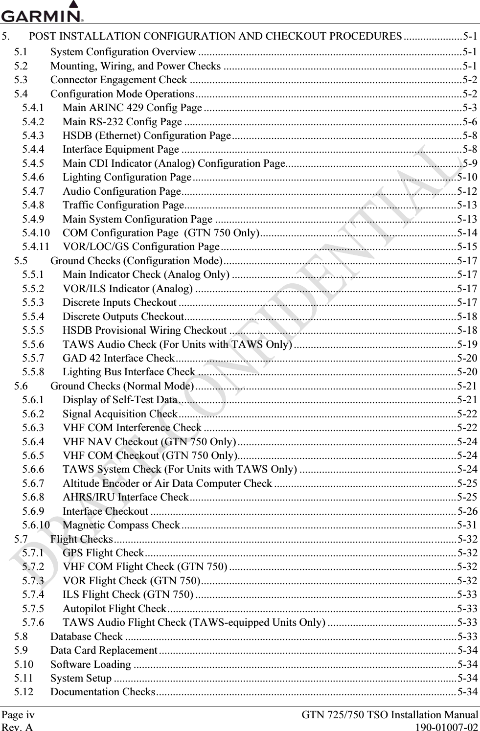
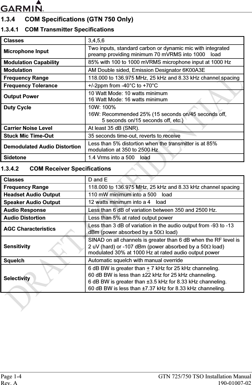
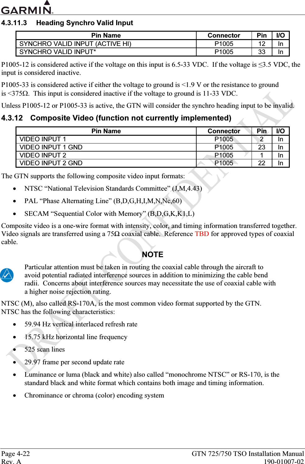
![GTN 725/750 TSO Installation Manual Page 3-1 190-01007-02 Rev. A 3. INSTALLATION PROCEDURES 3.1 Unit and Accessories For description of units see Table 1-1. Table 3-1. Catalog Part Numbers Model Unit Only Kit Standard Kit Unit P/N Color COM GTN 725 010-00819-00 010-00819-50 011-02281-00 BLK 010-00820-00 010-00820-50 011-02282-00 BLK 10W [1] GTN 750 010-00890-00 010-00890-50 011-02282-50 GRY [1] Unit is available with COM and is calibrated for both 10W and 16W COM; 16W COM is a software enablement feature using an enablement card. Table 3-2. Standard Kit Accessories Model Item Part Number Mounting Rack 115-01294-00 Connector Kit 011-02326-00 Back Plate Assembly 011-02246-00 GTN 725 Product Information Kit K00-00488-00 Mounting Rack 115-01294-00 Connector Kit 011-02326-02 Back Plate Assembly 011-02246-02 GTN 750 Product Information Kit K00-00488-00](https://usermanual.wiki/Garmin/01594/User-Guide-1434717-Page-39.png)
![Page 3-2 GTN 725/750 TSO Installation Manual Rev. A 190-01007-02 3.2 Optional Accessories 3.2.1 GPS Antenna Options For details regarding antenna selection, refer to Section 1.3.8. Once the antenna type is decided upon, refer to the information below for detailed parts information for antennas available directly from Garmin. Contact manufacturer directly for information on other antennas. GA 35 Antenna: GA 35 Antenna Garmin P/N 013-00235-00 contains the following items: ITEM PART NUMBER QTY 013-00235-00 (Garmin) GA 35 GPS/WAAS Antenna [1] AT575-93G (Aero Antenna) 1 [1] Antenna includes 8-32 UNC-2A x 1.00” SS 303 mounting screws (qty 4) and O-ring (qty 1). An antenna doubler may also be required. Refer to the appropriate antenna installation data. To secure the antenna #8 washers (qty 4) and #8 (qty 4) self-locking nuts are required in addition to the antenna, or suitable nutplates may be installed on the doubler. To connect the GPS antenna coaxial cable to the antenna a TNC plug is required. GA 36 Antenna: GA 36 Antenna Garmin P/N 013-00244-00 contains the following items: ITEM PART NUMBER QTY 013-00244-00 (Garmin) GA 36 GPS/WAAS Antenna [1] AT575-126G (Aero Antenna) 1 [1] Antenna includes 8-32 UNC-2A x 1.00” SS 303 mounting screws (qty 4) and O-ring (qty 1). An antenna doubler may also be required. Refer to the appropriate antenna installation data. To secure the antenna #8 washers (qty 4) and #8 (qty 4) self-locking nuts are required in addition to the antenna, or suitable nutplates may be installed on the doubler. To connect the GPS antenna coaxial cable to the antenna a TNC plug is required. GA 37 Antenna: GA 37 Antenna Garmin P/N 013-00245-00 contains the following items: ITEM PART NUMBER QTY 013-00245-00 (Garmin) GA 37 GPS/WAAS + XM Antenna [1] AT2300-126G (Aero Antenna) 1 [1] Antenna includes 8-32 UNC-2A x 1.00” SS 303 mounting screws (qty 4) and O-ring (qty 1). An antenna doubler may also be required. Refer to the appropriate antenna installation data. To secure the antenna #8 washers (qty 4) and #8 (qty 4) self-locking nuts are required in addition to the antenna, or suitable nutplates may be installed on the doubler. To connect the GPS antenna coaxial cable to the antenna a TNC plug is required. A33W Antenna: ITEM PART NUMBER QTY A33W, WAAS [1] 013-00261-00 (Garmin) 1 [1] Antenna includes 6-32 UNC-2A x 1.00” SS 303 mounting screws (qty 4) and O-ring (qty 1). An antenna doubler may also be required. To secure the antenna, #6 washers (qty 4) and #6 (qty 4) self-locking nuts are required in addition to the antenna, or suitable nutplates may be installed on the doubler that is used. To connect the GPS antenna coaxial cable to the antenna a TNC plug is required.](https://usermanual.wiki/Garmin/01594/User-Guide-1434717-Page-40.png)
![Page 3-6 GTN 725/750 TSO Installation Manual Rev. A 190-01007-02 Table 3-4. Socket Contact Part Numbers Configuration Module 78-pin Connector (P1001) P1001-P1005 Wire Gauge 28 AWG [1] 22-28 AWG [2] Garmin P/N 336-00021-00 336-00021-00 Military P/N N/A M39029/58-360 AMP N/A 204370-2 Positronic N/A MC8522D ITT Cannon N/A 010-2042-000 Notes: [1] For configuration module pins, ensure that the crimp tool is set to crimp 28 AWG wire (indenter setting of ‘4’). [2] Contacts listed are not to be used for configuration module wiring. Use the contacts supplied with the configuration module when installing configuration module wires in P1001.](https://usermanual.wiki/Garmin/01594/User-Guide-1434717-Page-44.png)

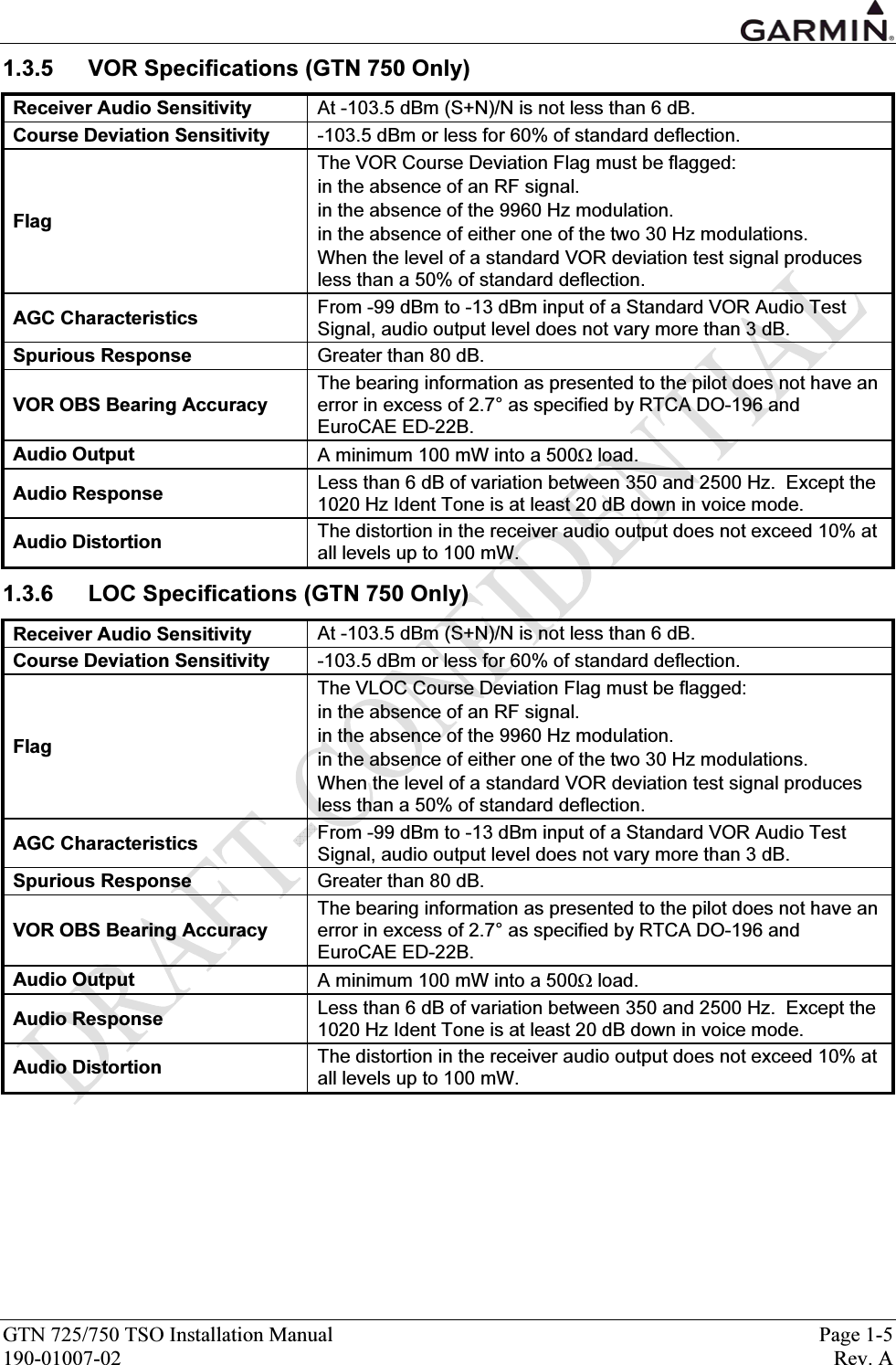
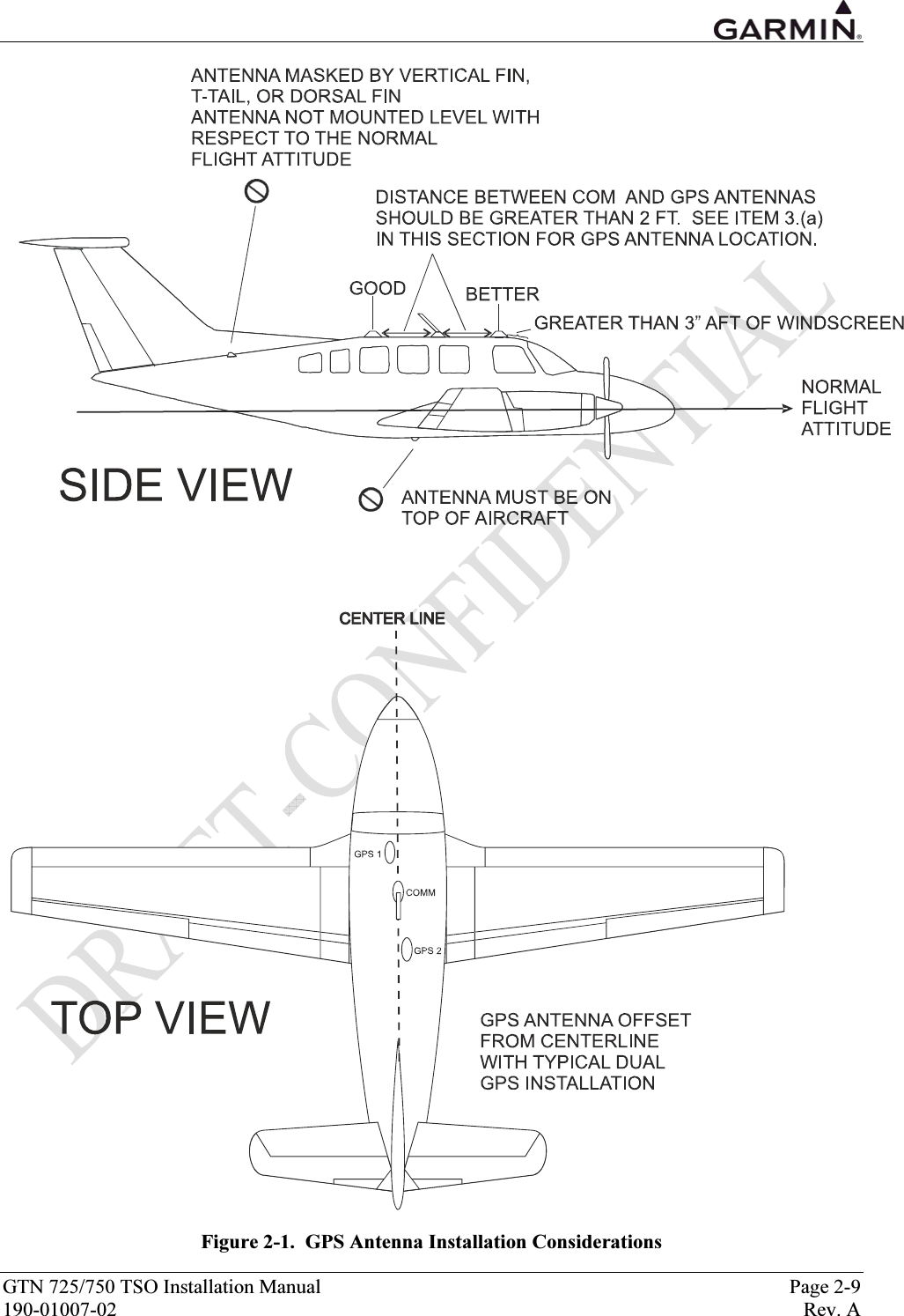
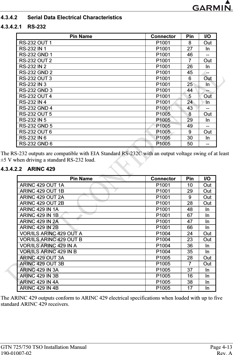
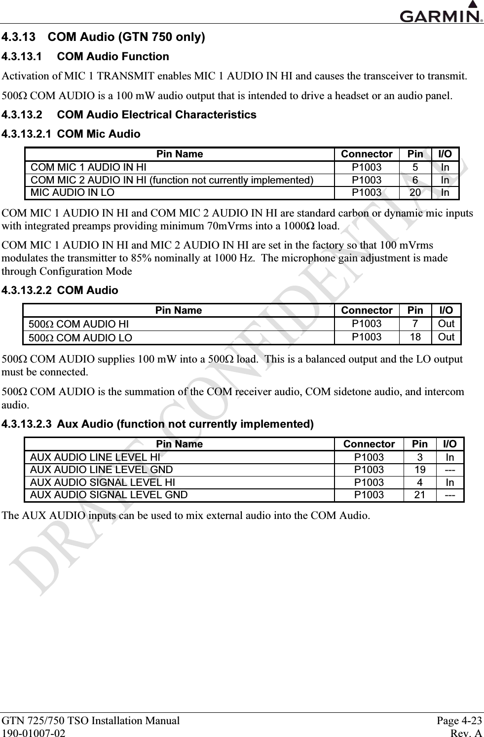
![GTN 725/750 TSO Installation Manual Page 4-11 190-01007-02 Rev. A 4.3.4.1.2 ARINC 429 The data output on the ARINC 429 OUT ports depends on the configuration (see Section TBD). Below is a list of the configurations and the labels output for each one: • ARINC 429 • GAMA 429 • GAMA 429 Graphics • GAMA 429 Graphics w/Int • GAMA 429 Pro Line 21 • GAMA 429 Sextant • GAMA 429 Bendix King Label # Parameter Name 1 2 3 4 5 6 7001 Distance to Go (BCD) ● ● ● ● ● ● ●002 Time to Go (BCD) ● ● ● ● ● ● ●012 Ground Speed (BCD) ● ● ● ● ● ● ●074G Data Record Header ● ● ● ● ● ●075G Active Wpt From/To Data ● ● ● ● ● ●100 Selected Course 1 ● 100P Selected Course 1 ● ● ● ● ● ●113G Message Checksum ● ● ● ● ● ●114 Desired Track (True) ● ● ● ● ● ● ●115 Waypoint Bearing (True) ● ● ● ● ● ● ●116 Cross Track Distance ● 116G [1] Cross Track Distance ● ● ● ● ● ●117G Vertical Deviation ● ● ● ● ● 117P Vertical Deviation ●121 Horizontal Command (to Autopilot) ● ● ● ● ● ● ●125 Greenwich Mean Time (BCD) ● ● ● ● ● ● ●147G Magnetic Variation ● ● ● ● ● ●251 Distance to Go ● 251G Distance to Go ● ● ● ● ● ●252 Time to Go ● ● ● ● ● ● ●260G Date (BCD) ● ● ● ● ● ●261G GPS Discrete Word 1 ● ● ● ● ● ●275G LRN Status Word ● ● ● ● ● ●300G Station Declination, Type, and Class ● ● ● ● ● ●303 Message Length/Type/Number ● ● ● ● ● ●304G Message Characters 1-3 ● ● ● ● ● ●305G Message Characters 4-6 ● ● ● ● ● ●306G NAV/Waypoint/Airport Latitude ● ● ● ● ● ●307G NAV/Waypoint/Airport Longitude ● ● ● ● ● ●310 Present Position Latitude ● ● ● ● ● ● ●311 Present Position Longitude ● ● ● ● ● ● ●312 Ground Speed ● ● ● ● ● ● ●313 Track Angle (True) ● ● ● ● ● ● ●314 True Heading ● ● ● ● ● ● ●315 Wind Speed ● ● ● ● ● ● ●316 Wind Angle (True) ● ● ● ● ● ● ●320 Magnetic Heading ● ● ● ● ● ● ●](https://usermanual.wiki/Garmin/01594/User-Guide-1434717-Page-59.png)
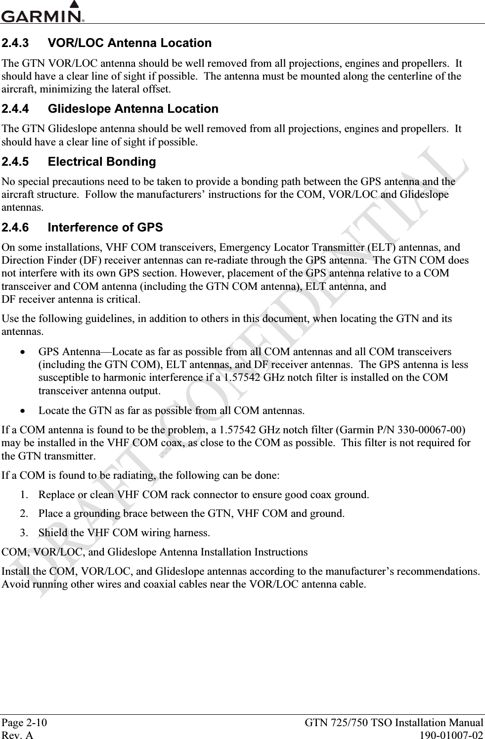
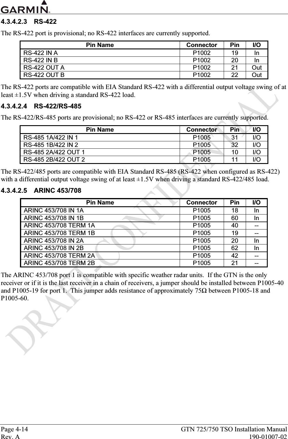
![Page 4-12 GTN 725/750 TSO Installation Manual Rev. A 190-01007-02 Label # Parameter Name 1 2 3 4 5 6 7321 Drift Angle ● ● ● ● ● ● ●326G [1] Lateral Scale Factor ● ● ● ● ● ●327G Vertical Scale Factor ● ● ● ● ● 330 Conic Arc Inbound Course ● ● 331 Conic Arc Radius ● ● 332 Conic Arc Course Change Angle ● ● 333 Airport Runway Azimuth ● ● 334 Airport Runway Length in Feet ● ● 335 Left/Right Hand Holding Pattern Azimuth ● ● 340 Left/Right Hand Procedure Turn Azimuth ● ● 351G Distance to Destination (Via Flight Plan) ● ● ● ● ● ●352G Estimated Time to Destination (Via Flight Plan) ● ● ● ● ● ●371G Specific Equipment ID ● ● ● ● ● ●377 Equipment Hex ID Code ● ● ● ● ● ● ●[1] Label 116G and 326G utilize the optional resolution extension bits (bits 11-13). The following labels are output on the VOR/ILS ARINC 429 OUT port: Label # Parameter Name 034G VOR/ILS Frequency (BCD) 035G DME Frequency (BCD) 100G Selected Course #1 173 Localizer Deviation 174 Glideslope Deviation 222 VOR Omnibearing 371G Specific Equipment ID 377 Equipment Hex ID Code The labels recognized on the ARINC 429 IN ports depend on the configuration (see Section TBD). 4.3.4.1.3 ARINC 453/708 The GTN can receive ARINC 453/708 weather radar data from specific weather radars. For more information, refer to Section TBD.](https://usermanual.wiki/Garmin/01594/User-Guide-1434717-Page-60.png)
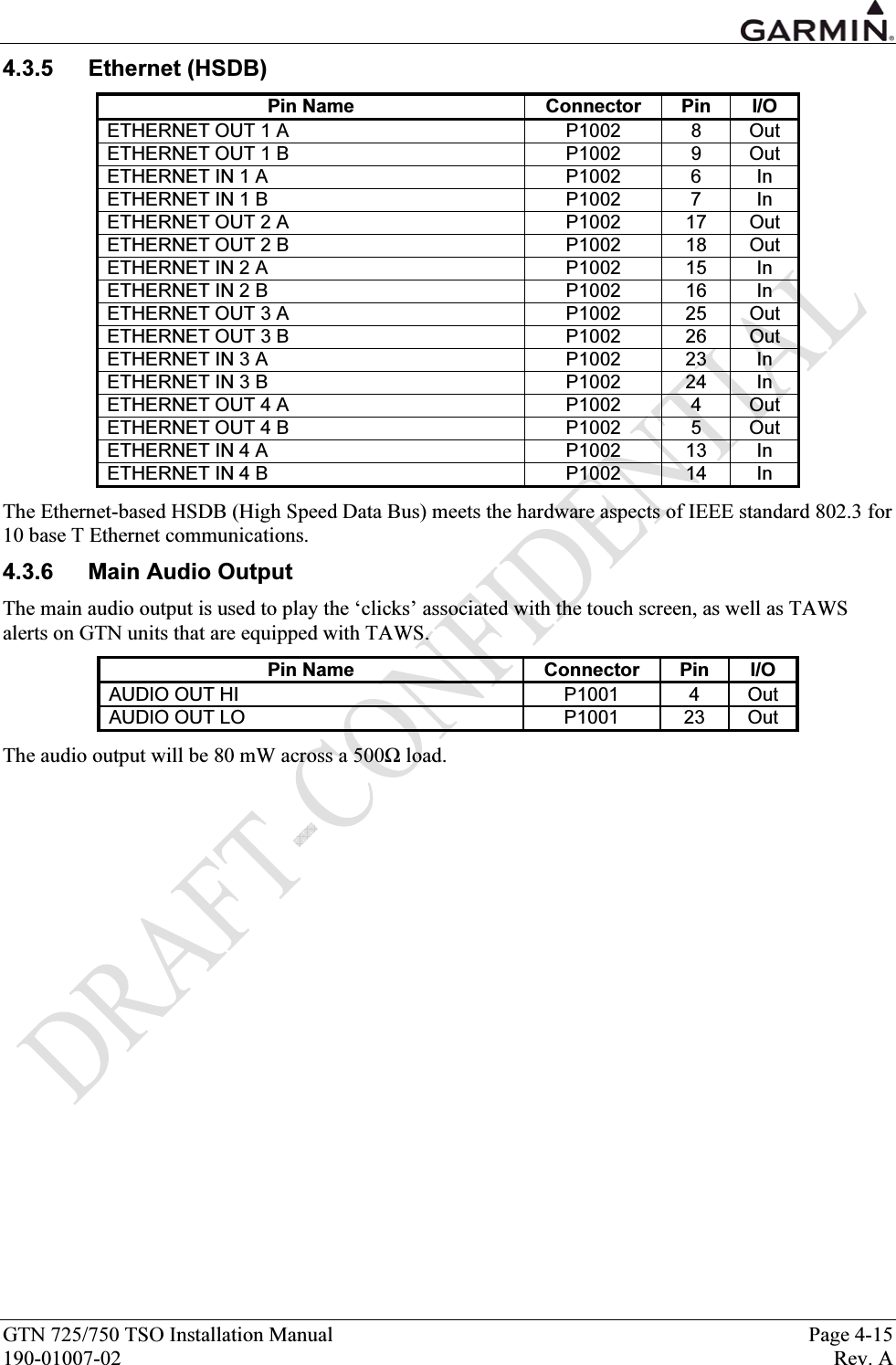
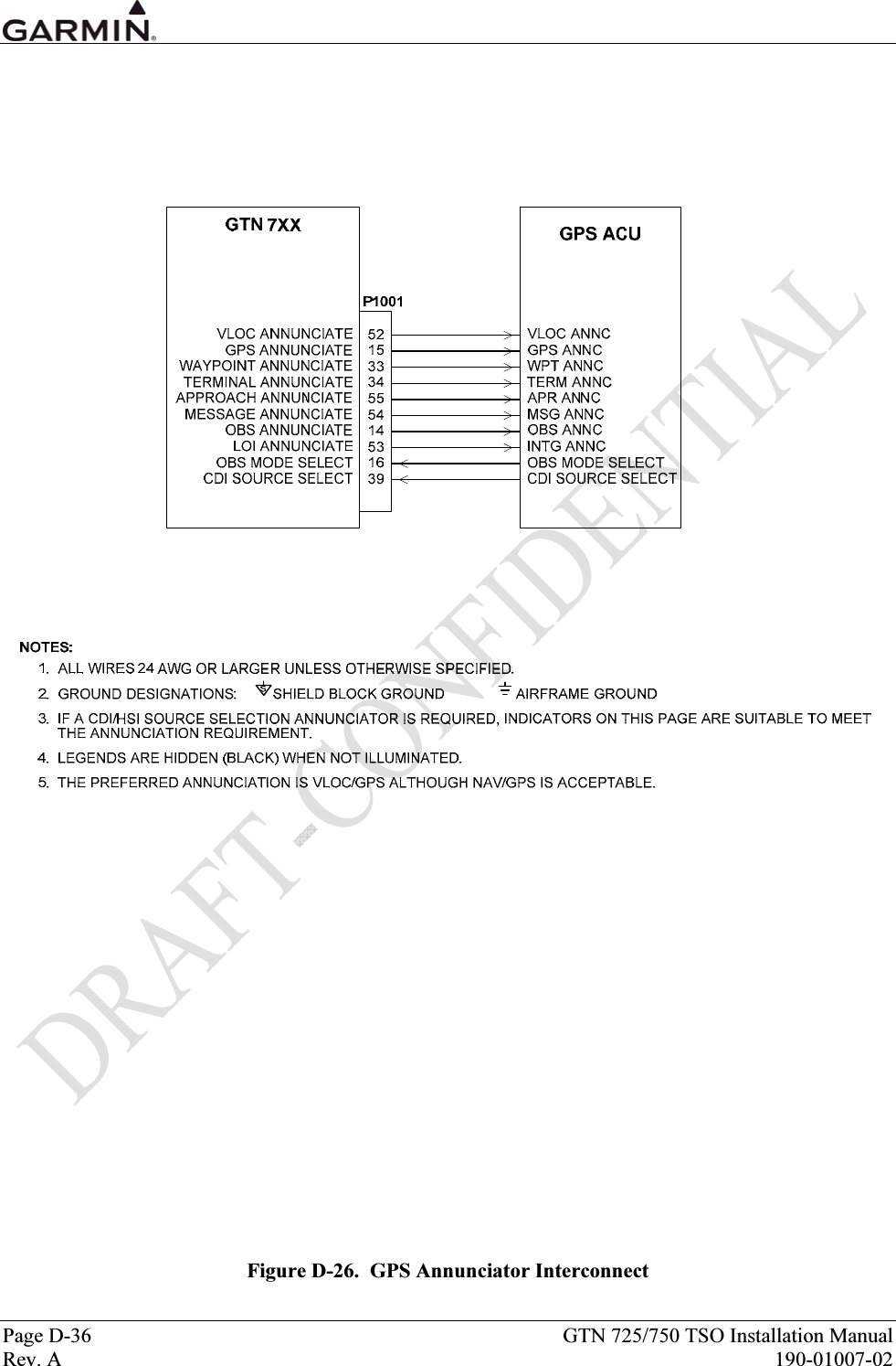
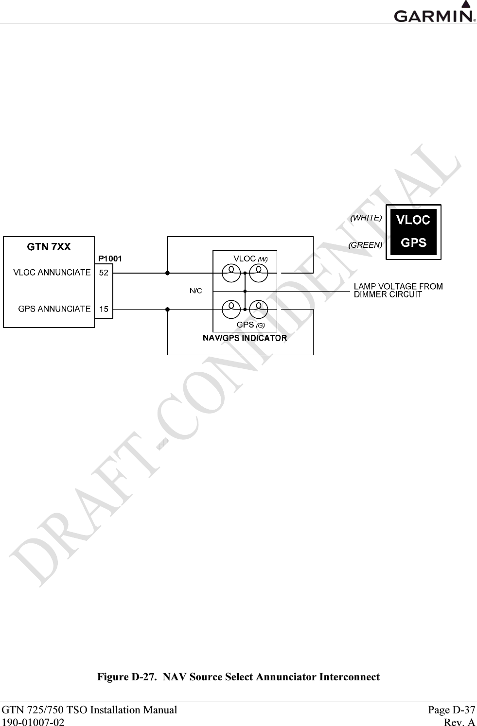
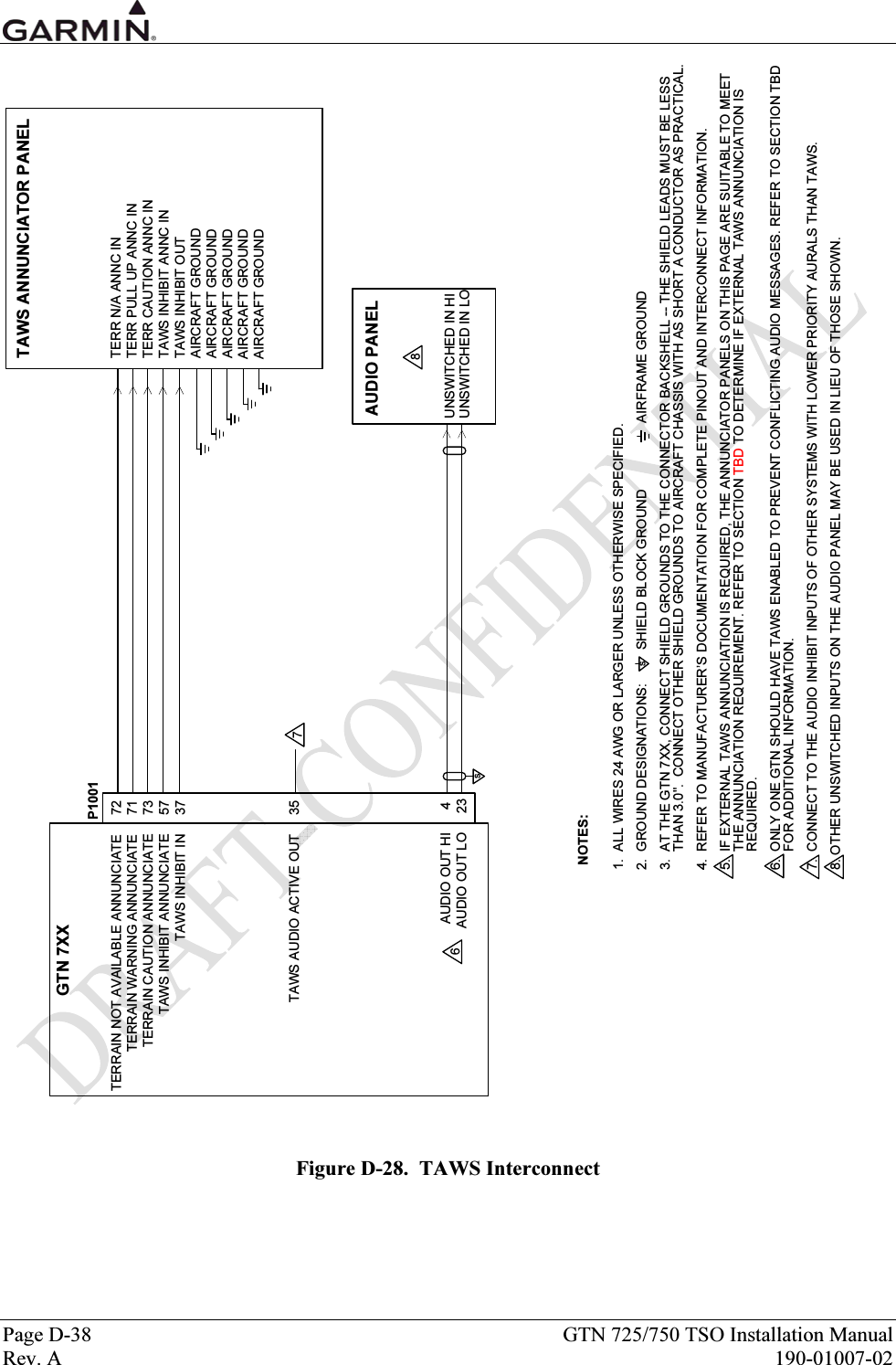
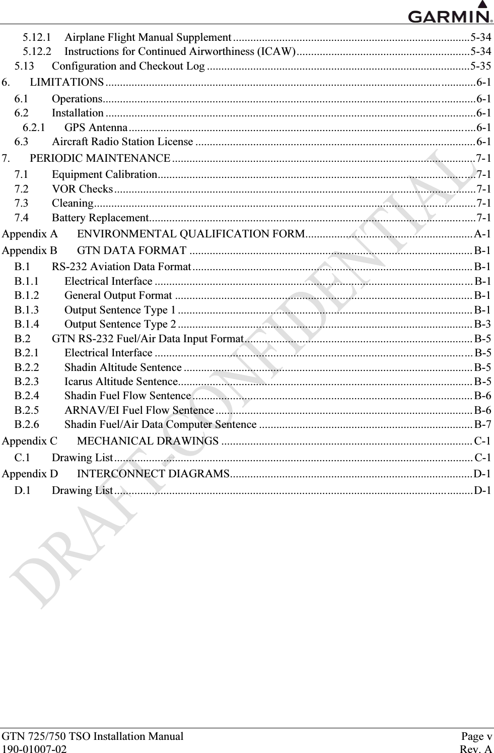
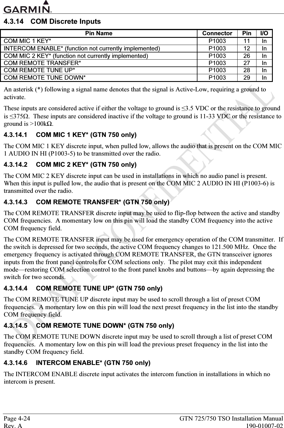
![GTN 725/750 TSO Installation Manual Page 4-19 190-01007-02 Rev. A 4.3.10 Discrete Outputs Pin Name Connector Pin I/O OBS ANNUNCIATE* P1001 14 Out GPS ANNUNCIATE* P1001 15 Out WAYPOINT ANNUNCIATE* P1001 33 Out TERMINAL ANNUNCIATE* P1001 34 Out TAWS AUDIO ACTIVE OUT P1001 35 Out VLOC ANNUNCIATE* P1001 52 Out LOI ANNUNCIATE* P1001 53 Out MESSAGE ANNUNCIATE* P1001 54 Out APPROACH ANNUNCIATE* P1001 55 Out ILS/GPS APPROACH* P1001 56 Out TAWS INHIBIT ANNUNCIATE* P1001 57 Out TERRAIN WARNING ANNUNCIATE* P1001 71 Out TERRAIN NOT AVAILABLE ANNUNCIATE* P1001 72 Out TERRAIN CAUTION ANNUNCIATE* P1001 73 Out GPS SELECT* [1] P1001 74 Out TRAFFIC TEST* P1001 75 Out TRAFFIC STANDBY* P1001 76 Out SPARE DISC OUT A* P1002 3 Out SPARE DISC OUT B* P1002 12 Out WX RADAR ON* (function not currently implemented) P1005 13 Out SPARE OUTPUT C* P1005 34 Out [1] The operation of the GPS SELECT can be configured. An asterisk (*) following a signal name denotes that the signal is Active-Low, producing a low (ground) on the output when active. All discrete outputs from the GTN are Active-Low. Each is an “open drain” output capable of sinking 500 mA when active. 4.3.10.1 OBS ANNUNCIATE* The OBS ANNUNCIATE output is driven to indicate GPS OBS mode of operation. This output is active when the OBS or SUSP annunciation is on the display. 4.3.10.2 GPS ANNUNCIATE* (GTN 750 Only) The GPS ANNUNCIATE output is driven when the unit is configured with a single CDI/HSI and the GPS data is being displayed on the CDI/HSI. This output parallels the GPS annunciation on the display. 4.3.10.3 WAYPOINT ANNUNCIATE* The WAYPOINT ANNUNCIATE output is driven in the following manner: 1. When the aircraft is within 10 seconds of reaching the turning point for a course change, the waypoint annunciator flashes. 2. When the aircraft is in a turn, the waypoint annunciator illuminates and remains illuminated until the turn is completed. 3. When a user arrival alarm is set and the aircraft is within the circle defined by the arrival alarm radius at the arrival waypoint, the waypoint annunciator flashes for 10 seconds. 4. When a user arrival alarm is not set and the aircraft is within 10 seconds of reaching the arrival waypoint, the waypoint annunciator flashes.](https://usermanual.wiki/Garmin/01594/User-Guide-1434717-Page-67.png)
![GTN 725/750 TSO Installation Manual Page 5-5 190-01007-02 Rev. A DATA OUT SELECTIONS Selection [1] Description Off No unit(s) connected to ARINC 429 output ARINC 429 Standard ARINC 429 output data (non-GAMA). GAMA 429 Bendix King ARINC 429 data as defined by the GAMA General Aviation Subset, 2nd Edition. The output data includes navigation, flight plan and GPS vertical guidance information to the following systems: Bendix/King EFS 40/50 (GPS vertical guidance provided on EFIS) GAMA 429 ARINC 429 data as defined by the General Aviation Manufacturers’ Association (GAMA) General Aviation Subset, 2nd Edition. The output data includes navigation and flight plan information to the following systems: Garmin GAD 42 Interface Adapter Bendix/King EFS 40/50 (No GPS vertical guidance provided) Collins EFIS 84 Certain other versions of Collins EFIS may also be compatible with this format. GAMA 429 Graphics ARINC 429 data as defined by the GAMA General Aviation Subset, 2nd Edition including GAMA Graphics Protocol ‘A’. This format outputs intersection symbols as generic waypoint symbols. The output data includes navigation and flight plan information (including graphical representation of flight plan procedures) to the following EFIS systems: Honeywell Primus 1000 GAMA 429 Grph w/Int ARINC 429 data as defined by the GAMA General Aviation Subset, 2nd Edition including GAMA Graphics Protocol ‘A’. The output data includes navigation and flight plan information (including graphical representation of flight plan procedures) to the following systems: Sandel SN3308 Sandel SN3500/4500 GAMA 429 Pro Line 21 ARINC 429 data as defined by the GAMA General Aviation Subset, 2nd Edition. The output data includes navigation and flight plan information to the following EFIS systems: Collins Pro Line 21 GAMA 429 Sextant ARINC 429 data as defined by the GAMA General Aviation Subset, 2nd Edition. The output data includes navigation and flight plan information to the following EFIS systems: Sextant SMD 45 [1] Garmin GTX 330 will work with any output setting SDI Selection Description Common RX: Accepts all 429 inputs TX: Generates all 429 outputs with SDI = 0. LNAV 1 Number 1 (Pilot) long-range navigator RX: Accepts 429 inputs with SDI = 0 or 1. TX: Generates all 429 outputs with SDI = 1. LNAV 2 Number 2 (Copilot) long-range navigator RX: Accepts 429 inputs with SDI = 0 or 2. TX: Generates all 429 outputs with SDI = 2.](https://usermanual.wiki/Garmin/01594/User-Guide-1434717-Page-81.png)
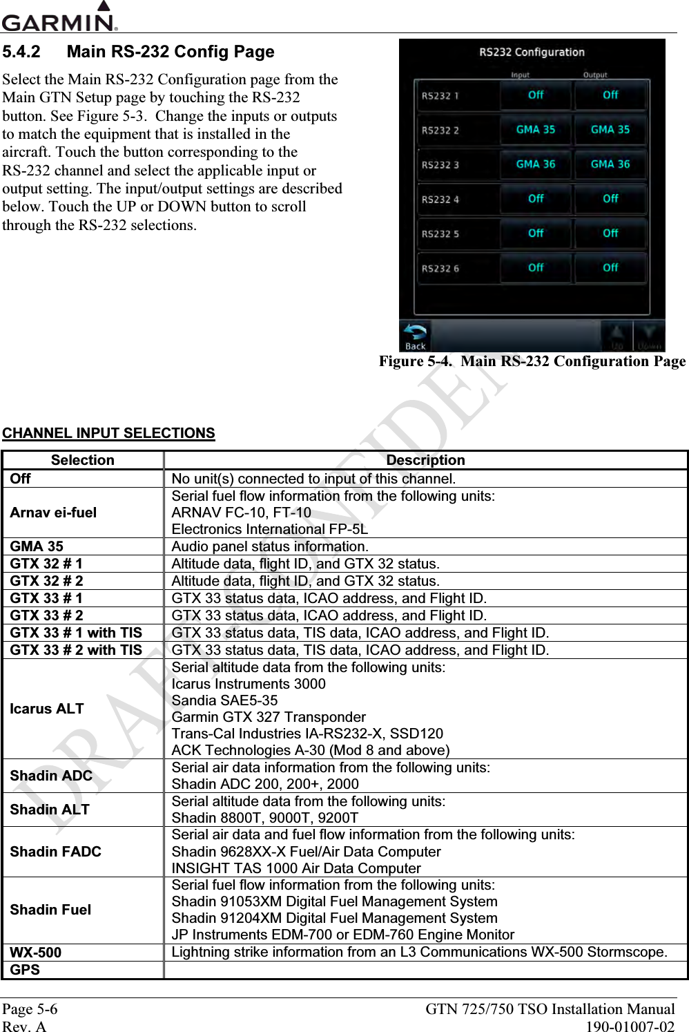
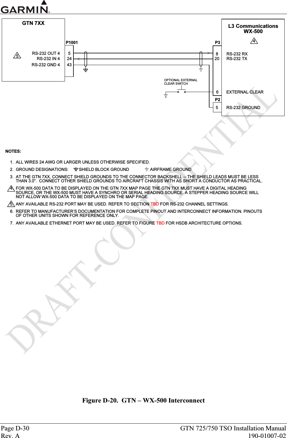
![GTN 725/750 TSO Installation Manual Page 5-7 190-01007-02 Rev. A CHANNEL OUTPUT SELECTIONS Selection Description Off No unit(s) connected to output of this channel. ADS-B Serial communication to Garmin GTX 33/330 ES or 33D/330D ES Transponders. Aviation Output Serial position, altitude, velocity, and navigation data to the following units: Argus 3000, 5000, or 7000 Moving Map Electronics International FP-5L Fuel Flow Computer (non-TSO’d) Garmin MX20 (V5.6 or later), GMX 200 [1] Garmin GPSMAP 195, GPSMAP 295 or GPS III Pilot Garmin GPSMAP 196, GPSMAP 296, and GPSMAP 396 Garmin GTX 327 Transponder JP Instruments EDM-700 or EDM-760 Engine Monitor Shadin 91204XM Digital Fuel Management System Shadin 91053XM Digital Fuel Management System Shadin 9628XX-X Fuel/Air Data Computer Stormscope Series II (with NAVAID) Moving Map Aviation (no Altitude) Serial position, velocity, and navigation data to the following units: Garmin MX20 (V5.5 or earlier) Horizon DDMP INSIGHT TAS 1000 Air Data Computer Honeywell EGPWS Serial communication to a Bendix/King (Honeywell) KGP 560 EGPWS. GMA 35 Control of GMA 35 Audio Panel functions. GTX 32 # 1 Control of GTX 32 transponder functions, pressure altitude data, and groundspeed data. GTX 32 # 2 Control of GTX 32 transponder functions, pressure altitude data, and groundspeed data. GTX 33 # 1 with TIS Control of GTX 33 transponder functions, pressure altitude data, and groundspeed data. GTX 33 # 2 with TIS Control of GTX 33 transponder functions, pressure altitude data, and groundspeed data. MapMX Serial position, altitude, velocity, and navigation data to the following units: Garmin MX20 (V5.7 or later), GMX 200 WX-500 Serial communication to an L3 Communications WX-500 Stormscope. GPS](https://usermanual.wiki/Garmin/01594/User-Guide-1434717-Page-83.png)
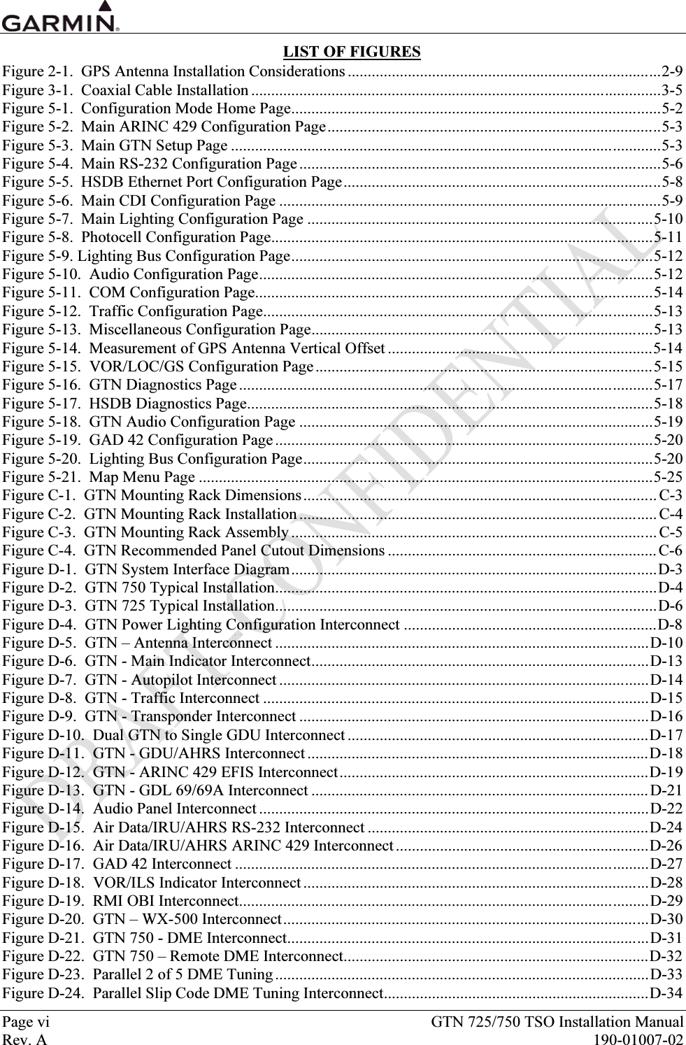
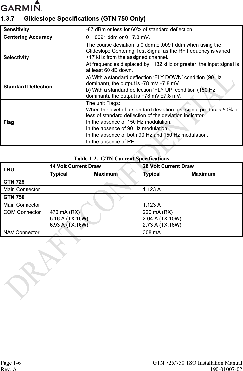
![GTN 725/750 TSO Installation Manual Page 5-35 190-01007-02 Rev. A 5.13 Configuration and Checkout Log The completed checkout log sheet should be maintained with the aircraft permanent records. If a dual GTN installation is being done, a checkout log for each system must be completed. Table 5-1. GTN Post-Installation Checkout Log GTN Post-Installation Checkout Log Date: ____ /____ /____ By: ________________ INSTALLATION INFORMATION: Aircraft Model: _________________________ Unit P/N: ______________________________ Unit Model: ____________________________ GPS Antenna P/N:_______________________ Aircraft S/N: ________________Mod Level: _________________S/N:_______________________GPS Ant Model _____________EXTERNAL ANNUNCIATION REQUIREMENT CDI/HSI SOURCE SELECTION ANNUNCIATION: GPS NAVIGATION ANNUNCIATION: Annunciation: Required Not Required Annunciation: Required Not Required [ N/A] Annunciator Installed [ N/A] Annunciators Installed CONNECTOR ENGAGEMENT CHECK Connector engagement checked CONFIGURATION ITEMS MAIN ARINC 429 CONFIGURATION MAIN LIGHTING In 1: High Low ____________________ Display Keys In 2: High Low ____________________ Source: ___________ __________ In 3: High Low ____________________ Resp Time / Min: ____ / _____ ____ / _____ In 4: High Low ____________________ Slope / Offset: ____ / _____ ____ / _____ Out 1: High Low ____________________ Photo Transition: ___________ [ N/A] Out 2: High Low ____________________ Photo Slp/Ofst: ____ / _____ [ N/A] Out 3: High Low ____________________ SDI: Common LNAV 1 LNAV 2 MAIN CDI/OBS CONFIG OBI Source: Always GPS Track CDI [ N/A] MAIN RS-232 CONFIGURATION (RX/TX) V-Flag State: Normal Declutter Chnl 1 _____________ / ________________ SEL CRS for GPS: Allow Ignore Chnl 2 _____________ / _________________ SEL CRS for VLOC: Allow Ignore Chnl 3 _____________ / _________________ CDI Key: Allow Ignore Chnl 4 _____________ / _________________ Chnl 5 _____________ / _________________ GPS VERTICAL OFFSET Chnl 6 _____________ / _________________ GPS Antenna Height Above Ground: _______ ft MAIN SYSTEM CONFIGURATION GAD 42 CONFIGURATION [ N/A] Fuel Type: ________________________ Main RMI/OBI: _____ Roll Steering: _____ Terrain Type: None TERRAIN TAWS NAV RMI/OBI: _____ Remote Crs Sel: _____ DISCRETES Sel Crs Drive: _____ TAS Input: _____ GPS SELECT: Auto Prompt Main RMI/OBI: _____ GPS/NAV 429 L/H: _____ COM PRESETS [ N/A]: Enabled Disabled Heading 429 L/H: _____ GAD SW Ver: _____________](https://usermanual.wiki/Garmin/01594/User-Guide-1434717-Page-111.png)
![Page 5-36 GTN 725/750 TSO Installation Manual Rev. A 190-01007-02 CONFIGURATION ITEMS (cont’d): TAWS AUDIO CONFIG 1 [ N/A] TAWS AUDIO CONFIG 2 (CONT’D) Voice: Female Male IOI – Caution: Caution, Obstacle (2x) Volume: ___________% Obstacle Ahead (2x) PDA – Caution: Too Low – Terrain IOI – Warning: Obstacle (2x); Pull Up (2x) EDR – Caution: Sink Rate Obstacle Ahead; Pull Up (2x) EDR – Warning: Pull Up VOR/LOC/GS CDI (GTN 750 only) NCR – Caution: Don’t Sink NAV Radio: Enabled Disabled VCO – Info Five Hundred TAWS AUDIO CONFIG 2 [ N/A] VOR/LOC/GS ARINC 429 CONFIGURATION RTC – Caution: Caution Terrain (2x) RX Speed: High Low Terrain Ahead (2x) TX Speed: High Low RTC – Warning: Terrain (2x); Pull Up (2x) SDI: Common VOR/ILS 1 VOR/ILS 2 Terrain Ahead, Pull Up (2x) ROC – Caution: Caution, Obstacle (2x) DME Mode: Directed freq 1 Directed freq 2 Obstacle Ahead (2x) DME Channel Mode: ___________________ ROC – Warning: Obstacle (2x); Pull Up (2x) Obstacle Ahead, Pull Up (2x) GDL Configuration [ N/A] ITI – Caution: Caution, Terrain (2x) Attenuation: ______________ Terrain Ahead (2x) Model: GDL 69A GDL 69 ITI– Warning: Terrain (2x), Pull Up (2x) Terrain Ahead, Pull Up (2x) After completing configuration and prior to checkout, restart unit for changes to take effect SYSTEM CHECKOUT GROUND CHECKS (CONFIGURATION MODE) MAIN ANALOG INDICATOR [ N/A] ANNUNCIATOR OUTPUTS CDI (left, centered, right) [ N/A] Approach (APR) VDI (down, centered, up) [ N/A] GPS Indicator (GPS) TO/FROM flag (OFF, TO, FROM) [ N/A] Integrity (INTEG) Valid flags [ N/A] Message (MSG) OBS (Selected Course) [ N/A] OBS Mode (OBS) [ N/A] Terminal Mode (TERM) VOR/ILS INDICATOR [ N/A] [ N/A] VLOC Indicator (VLOC) CDI (left, centered, right) [ N/A] Waypoint (WPT) VDI (down, centered, up) [ N/A] ILS/GPS Approach (ILS/GPS APR) TO/FROM flag (OFF, TO, FROM) [ N/A] GPS Select (GPS SELECT) Valid flags [ N/A] Terrain Caution (TER CAUT) [ N/A] Terrain Inhibit (TER INHB) DISCRETE INPUTS [ N/A] Terrain Not Available (TER N/A) [ N/A] Remote CDI Select [ N/A] Terrain Test (TER TEST) [ N/A] Remote OBS Select [ N/A] Terrain Warning (TER WARN) [ N/A] Terrain Inhibit [ N/A] COM Remote Recall](https://usermanual.wiki/Garmin/01594/User-Guide-1434717-Page-112.png)
![GTN 725/750 TSO Installation Manual Page 5-37 190-01007-02 Rev. A GROUND CHECKS (CONFIGURATION MODE) (CONT’D) ADC/ENCODER/FUEL/F/ADC AHRS/IRU/ADC [ N/A] Air Data Computer [ N/A] Air Data Computer [ N/A] Altitude Encoder (serial) [ N/A] AHRS/IRU [ N/A] Fuel Sensor [ N/A] Fuel / Air Data Computer TAWS AUDIO [ N/A] Audio checked ALTITUDE ENCODER Audio level adjusted [ N/A] Altitude Encoder (Gray code) [ N/A] Altitude Encoder (serial) GAD 42 [ N/A]GAD 42 Interface Adapter LIGHTING BUS [ N/A] Aircraft Lighting Bus GROUND CHECKS (NORMAL MODE) SIGNAL ACQUISITION CHECK TAWS SYSTEM [ N/A] Position checked TAWS System Test OK Signal reception checked Interference from other avionics checked INTERFACE CHECKS [ N/A] Honeywell EFS 40/50 VHF COM INTERFERENCE [ N/A] Sandel SN3308 VHF COM interference checked [ N/A] Sandel SN3500/4500 [ N/A] ARINC 429 Traffic System VHF NAV CHECKOUT (GTN 750 ONLY) [ N/A] Ryan TCAD VOR reception checked [ N/A] L-3 Communications Stormscope Localizer reception checked [ N/A] Garmin GMX 200 / MX20 Deviation needle and flag checked [ N/A] Garmin GDL 69/69A [ N/A] Crossfill check VHF COM CHECKOUT (GTN 750 ONLY) [ N/A] External RMI Receiver / Transmitter operation checked [ N/A] DME Tuning [ N/A] G600 System Antenna checked VSWR __________ MAGNETIC COMPASS CHECK [ N/A] Compass swing performed FLIGHT CHECKS GPS checked ILS checked (GTN 750 Only) COM checked (GTN 750 Only) Autopilot checked VOR checked (GTN 750 Only) TAWS aural level checked DATABASE CHECKS Database checked AFMS CHECKS Antenna type checked Autopilot coupling limitations checked Autopilot Mode transitions checked Completed AFMS inserted in AFM/POH COMMENTS:](https://usermanual.wiki/Garmin/01594/User-Guide-1434717-Page-113.png)


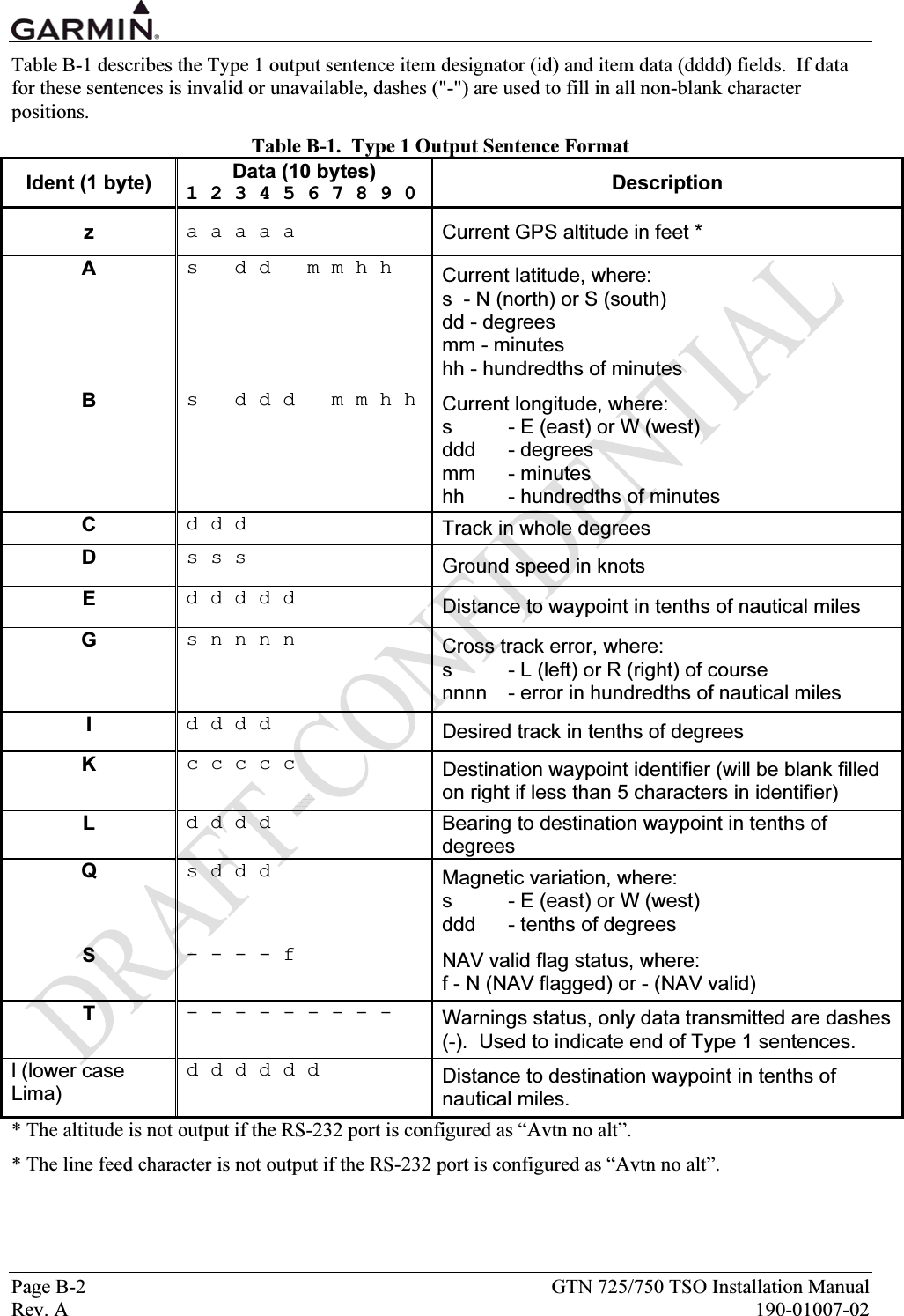
![GTN 725/750 TSO Installation Manual Page B-5 190-01007-02 Rev. A B.2 GTN RS-232 Fuel/Air Data Input Format B.2.1 Electrical Interface The input signals are compatible with RS-232C. Data is input at 9600 baud with a word length of 8 bits, one stop bit, and no parity. One message is received per second. B.2.2 Shadin Altitude Sentence The Garmin GTN is capable of receiving the following 17-byte message from Shadin Altitude Encoders, Altitude Serializers, and Altitude Converters: RMS<sp><+/->12345T<+/->12ul<CR> Where: RMS ASCII characters <sp> space (0x20) <+/-> sign indicator (0x2b["+"] or 0x2d["-"]) 12345 altitude in feet T ASCII character <+/-> sign indicator 12 sensor temperature ul checksum of bytes 1 through 14 in hex ASCII (i.e., "FA") <CR> carriage return (0x0d) Note: Checksum is calculated by adding each byte in the message (1 through 14). B.2.3 Icarus Altitude Sentence The Garmin GTN is capable of receiving the following 10-byte message from the Icarus Altitude Serializer: ALT<sp>12345<CR> Where: ALT ASCII characters <sp> space (0x20) 12345 altitude in feet <CR> carriage return (0x0d)](https://usermanual.wiki/Garmin/01594/User-Guide-1434717-Page-125.png)
![Page B-6 GTN 725/750 TSO Installation Manual Rev. A 190-01007-02 B.2.4 Shadin Fuel Flow Sentence The Garmin GTN is capable of receiving the following 55-byte message from the Shadin Fuel Flow Indicator: <STX>K0543.2<sp>0100.0<sp>0040.0<sp>0060.0<sp>0123.4<sp>0045.4<sp>0078.0<sp>123<ETX> Where: <STX> start-transmit character (0x02) K units designation (i.e., Gallons, Liters, Kilograms, B[pounds]) 0543.2 total fuel remaining (i.e., ASCII-coded decimal format: 0x30, 0x35, 0x34, 0x33, 0x2e, 0x32) <sp> space (0x20) 0100.0 fuel flow rate, total (formatted as for total fuel remaining) 0040.0 fuel flow rate, engine one (or asterisks["∗∗∗∗∗∗"], in the case of single engine aircraft) 0060.0 fuel flow rate, engine two (asterisks, in the case of single engine aircraft) 0123.4 fuel used, total 0045.4 fuel used, engine one (asterisks, in the case of single engine aircraft) 0078.0 fuel used, engine two (asterisks, in the case of single engine aircraft) 123 checksum (of bytes 2 through 51) <ETX> end-transmit character (0x03) Note: Checksum is calculated by adding each byte in the message (2 through 51), such that carries are discarded to give a one byte result. The ASCII-coded decimal representation of that byte is given, ranging from 0 (0x30, 0x30, 0x30) to 255 (0x32, 0x35, 0x35). B.2.5 ARNAV/EI Fuel Flow Sentence The Garmin GTN is capable of receiving the following 13-byte message from the ARNAV or Electronics International (“EI”) Fuel Flow Indicators: <STX>G0245100550<ETX> Where: <STX> start-transmit character (0x02 hex) G units designation (i.e., Gallons, Imperial gallons, Liters, Kilograms, B[pounds]) 0245 total fuel remaining in reverse order (i.e., ASCII-coded decimal format: 0x30, 0x32, 0x34, 0x35) 1 fuel remaining checksum (modulo 10 sum of four "total fuel remaining" digits) 0055 total fuel flow rate in reverse order 0 fuel flow checksum <ETX> end-transmit character (0x03) Note: Fuel remaining and fuel flow are [∗ 10] when units designation is gallons or imperial gallons. For example, 0245 gallons indicates 542 gallons; 0245 liters indicates 5420 liters. Checksum is the modulo 10 sum of the four fuel flow decimal digits, converted to an ASCII numerical character (e.g., checksum for "5678" would be ASCII "6").](https://usermanual.wiki/Garmin/01594/User-Guide-1434717-Page-126.png)
![GTN 725/750 TSO Installation Manual Page B-7 190-01007-02 Rev. A B.2.6 Shadin Fuel/Air Data Computer Sentence The Garmin GTN is capable of receiving the following message strings from the Shadin Fuel/Air Data or Air Data Computer: SHADIN “z” FORMAT <STX> ZA012<CR><LF> "ZA" (ASCII characters); "012" represents indicated Air Speed (knots) ZB345<CR><LF> "ZB" (ASCII characters); "345" represents true Air Speed (knots) ZC678<CR><LF> "ZC" (ASCII characters); "678" represents Mach Speed (thousandths) ZD<+/->9012<CR><LF> "ZD" (ASCII characters); sign; "9012" represents pressure altitude (tens of feet) ZE<+/->3456<CR><LF> "ZE" (ASCII characters); sign; "3456" represents density altitude (tens of feet) ZF<+/->78<CR><LF> "ZF" (ASCII characters); sign; "78" represents outside air temperature (Celsius) ZG<+/->90<CR><LF> "ZG" (ASCII characters); sign; "90" represents true air temperature (Celsius) ZH123<CR><LF> "ZH" (ASCII characters); "123" represents wind direction (degrees from north) ZI456<CR><LF> "ZI" (ASCII characters); "456" represents wind speed (knots) ZJ<+/->78<CR><LF> "ZJ" (ASCII characters); sign; "78" represents rate of turn (degrees per second) ZK<+/->901<CR><LF> "ZK" (ASCII characters); sign; "901" represents vertical speed (tens of ft/minute) ZL234<CR><LF> "ZL" (ASCII characters); "234" represents heading (degrees from north) ZM5678<CR><LF>† "ZM" (ASCII characters); "5678" represents fuel flow, right (tenths gallons/hour) ZN90123<CR><LF>† "ZN" (ASCII characters); "90123" represents fuel used, right (tenths gallons) ZO4567<CR><LF>† "ZO" (ASCII characters); "4567" represents fuel flow, left (tenths gallons/hour) ZP89012<CR><LF>† "ZP" (ASCII characters); "89012" represents fuel used, left (tenths gallons) ZQ345<CR><LF> "ZQ" (ASCII characters); "345" represents error log/reason indicator ZR678<CR><LF> "ZR" (ASCII characters); "678" represents checksum <ETX> Where: <STX> start-transmit character (0x02) <CR> carriage-return character (0x0d) <LF> line-feed character (0x0a) <+/-> sign indicator (0x2b["+"] or 0x2d["-"]) <ETX> end-transmit character (0x03) † Not available from Air Data Computer Note: Checksum is calculated by adding each byte in the message (including all characters from <STX> up to and including the error log/reason indicator), such that carries are discarded to give a one byte result. The ASCII-coded decimal representation of that byte is given, ranging from 0 (0x30, 0x30, 0x30) to 255 (0x32, 0x35, 0x35).](https://usermanual.wiki/Garmin/01594/User-Guide-1434717-Page-127.png)
![Page B-8 GTN 725/750 TSO Installation Manual Rev. A 190-01007-02 SHADIN “G” FORMAT <STX> GA012<CR><LF> "GA" (ASCII characters); "012" represents indicated Air Speed (knots) GB345<CR><LF> "GB" (ASCII characters); "345" represents true Air Speed (knots) GC678<CR><LF> "GC" (ASCII characters); "678" represents Mach Speed (thousandths) GD<+/->9012<CR><LF> "GD" (ASCII characters); sign; "9012" represents pressure altitude (tens of feet) GE<+/->3456<CR><LF> "GE" (ASCII characters); sign; "3456" represents density altitude (tens of feet) GF<+/->78<CR><LF> "GF" (ASCII characters); sign; "78" represents outside air temperature (Celsius) GG<+/->90<CR><LF> "GG" (ASCII characters); sign; "90" represents true air temperature (Celsius) GH123<CR><LF> "GH" (ASCII characters); "123" represents wind direction (degrees from north) GI456<CR><LF> "GI" (ASCII characters); "456" represents wind speed (knots) GJ<+/->78<CR><LF> "GJ" (ASCII characters); sign; "78" represents rate of turn (degrees per second) GK<+/->901<CR><LF> "GK" (ASCII characters); sign; "901" represents vertical speed (tens of ft/minute) GL234<CR><LF> "GL" (ASCII characters); "234" represents heading (degrees from north) GM5678<CR><LF>† "GM" (ASCII characters); "5678" represents fuel flow, right (Twin only) (tenths gallons/hour) GN90123<CR><LF>† "GN" (ASCII characters); "90123" represents fuel used, right (Twin only) (tenths gallons) GO4567<CR><LF> "GO" (ASCII characters); "4567" represents fuel flow, left (or Single) (tenths gallons/hour) GP89012<CR><LF> "GP" (ASCII characters); "89012" represents fuel used, left (or Single) (tenths gallons) GQ001<CR><LF> "GQ" (ASCII characters); "001" represents error log/reason indicator (001 = temp. sensor error, 000 = no errors) GR6789.0<CR><LF>† "GR" (ASCII characters); "6789.0" represents fuel remaining (gallons) Ga<+/->1234<CR><LF> "Ga" (ASCII characters); sign; "12.34" represents barometric corrected altitude (tens of feet) Gb56.78<CR><LF> "Gb" (ASCII characters); "56.78" represents current barometric pressure setting (inches Hg) G*901<CR><LF> "G*" (ASCII characters); "901" represents checksum <ETX> Where: <STX> start-transmit character (0x02) <CR> carriage-return character (0x0d) <LF> line-feed character (0x0a) <+/-> sign indicator (0x2b["+"] or 0x2d["-"]) <ETX> end-transmit character (0x03) † Not available from Airdata Computer Note: Checksum is calculated by adding each byte in the message (including all characters from <STX> up to and including the error log/reason indicator), such that carries are discarded to give a one byte result. The ASCII-coded decimal representation of that byte is given, ranging from 0 (0x30, 0x30, 0x30) to 255 (0x32, 0x35, 0x35).](https://usermanual.wiki/Garmin/01594/User-Guide-1434717-Page-128.png)
![GTN 725/750 TSO Installation Manual Page B-9 190-01007-02 Rev. A SHADIN “S” FORMAT <STX> SA012<CR><LF> "SA" (ASCII characters); "012" represents indicated Air Speed (knots) SB345<CR><LF> "SB" (ASCII characters); "345" represents true Air Speed (knots) SC678<CR><LF> "SC" (ASCII characters); "678" represents Mach Speed (thousandths) SD<+/->9012<CR><LF> "SD" (ASCII characters); sign; "9012" represents pressure altitude (tens of feet) SE<+/->3456<CR><LF> "SE" (ASCII characters); sign; "3456" represents density altitude (tens of feet) SF<+/->78<CR><LF> "SF" (ASCII characters); sign; "78" represents outside air temperature (Celsius) SG<+/->90<CR><LF> "SG" (ASCII characters); sign; "90" represents true air temperature (Celsius) SH123<CR><LF> "SH" (ASCII characters); "123" represents wind direction (degrees from north) SI456<CR><LF> "SI" (ASCII characters); "456" represents wind speed (knots) SJ<+/->78<CR><LF> "SJ" (ASCII characters); sign; "78" represents rate of turn (degrees per second) SK<+/->901<CR><LF> "SK" (ASCII characters); sign; "901" represents vertical speed (tens of ft/minute) SL234<CR><LF> "SL" (ASCII characters); "234" represents heading (degrees from north) SM5678<CR><LF> "SM" (ASCII characters); "5678" represents fuel flow, right (tenths gallons/hour) SN90123<CR><LF> "SN" (ASCII characters); "90123" represents fuel used, right (tenths gallons) SO4567<CR><LF> "SO" (ASCII characters); "4567" represents fuel flow, left (tenths gallons/hour) SP89012<CR><LF> "SP" (ASCII characters); "89012" represents fuel used, left (tenths gallons) SQ345<CR><LF> "SQ" (ASCII characters); "345" represents error log/reason indicator SR67890<CR><LF> "SR" (ASCII characters); "67890" represents fuel remaining (tenths gallons) SS123<CR><LF> "SS" (ASCII character); "123" represents ground speed (knots) ST456<CR>LF> "ST" (ASCII character); "456" represents track (degrees) SU789012<CR><LF> "SU" (ASCII character); "789012" represents distance to waypoint (hundredths nautical miles) SV<E/W>345<CR><LF> "SV" (ASCII character); “E” represents East, “W” represents West; "345" represents magnetic variation (tenths degrees) SW<N/S>67 8901<CR><LF>"SW" (ASCII character); “N” represents North, “S” represents South; "67 8910" represents current latitude (degrees, minutes, hundredths of minutes) SX<E/W>234 5678<CR><LF>"SX" (ASCII character); “E” represents East, “W” represents West; "234 5678" represents current longitude (degrees, minutes, hundredths of minutes) SY<L/R>90<CR><LF> "SY" (ASCII character); “L” represents Left, “R” represents Right; "90" represents drift angle (degrees) Sa<+/->1234<CR><LF> "Sa" (ASCII character); sign; "1234" represents barometric corrected altitude (tens of feet) Sb56.78<CR><LF> "Sb" (ASCII character); "56.78" represents current barometric pressure setting (inches Hg) S*901<CR><LF> “S*” (ASCII character); "901" represents checksum <ETX> Where: <STX> start-transmit character (0x02) <CR> carriage-return character (0x0d) <LF> line-feed character (0x0a) <+/-> sign indicator (0x2b["+"] or 0x2d["-"]) <ETX> end-transmit character (0x03) Note: Checksum is calculated by adding each byte in the message (including all characters from <STX> up to and including the error log/reason indicator), such that carries are discarded to give a one byte result. The ASCII-coded decimal representation of that byte is given, ranging from 0 (0x30, 0x30, 0x30) to 255 (0x32, 0x35, 0x35).](https://usermanual.wiki/Garmin/01594/User-Guide-1434717-Page-129.png)