Garmin 01641 MARINE RADAR TRANSMITTER User Manual USERS MANUAL
Garmin International Inc MARINE RADAR TRANSMITTER USERS MANUAL
Garmin >
USERS MANUAL
GMR™ 600/1200 Series Radar Installation Instructions
Properly install your GMR 600/1200 series radar according to the following instructions.
®
Before installing your GMR 600/1200 series radar, conrm that the package contains the items listed on the box. If any parts are missing,
contact your Garmin dealer immediately.
See the Important Safety and Product Information guide in the product box for product warnings and other important information.
Always wear safety goggles, ear protection, and a dust mask when drilling, cutting, or sanding.
The selected radar mounting location must be able to hold the weight of the radar and withstand any inertial forces.
The radar transmits electromagnetic energy. It is important that the radar is turned off or the DC power input is disconnected when
personnel are required to come close to the radar to perform work on the radar assembly or associated equipment. Electromagnetic energy is harmful.
When the radar is transmitting, do not look directly at the antenna at close range, because the eyes are the most sensitive part of the body to
electromagnetic energy.
When drilling or cutting, always check the opposite side of the drilling or cutting surface.
Product Registration
Help us better support you by completing our online registration today. Go to http://my.garmin.com. Keep the original sales receipt, or a
photocopy, in a safe place.
Contact Garmin
Contact Garmin Product Support if you have any questions while installing your GMR 600/1200 series radar. In the USA, go to www.garmin
.com/support, or contact Garmin USA by phone at (913) 397.8200 or (800) 800.1020.
In the UK, contact Garmin (Europe) Ltd. by phone at 0808 2380000.
In Europe, go to www.garmin.com/support and click for in-country support information, or contact Garmin (Europe) Ltd. by
phone at +44 (0) 870.8501241.
Needed Tools
For Installing the Radar:
#2 Phillips screwdriver
5 mm Allen wrench
Drill and drill bits
Wrench and socket set
For Installing the Optional Field-Installable RJ-45 Network Connector:
Knife
Pliers
15 mm wrench
AMP modular-plug hand tool and die set or compatible equivalent
•
•
•
•
•
•
•
•
May, 2009 190-01067-02 Rev. A Printed in Taiwan
2 GMR 600/1200 Series Installation Instructions
Selecting a Location
When selecting a location to install the GMR 600/1200 series radar, consider the following:
An ideal mounting location is high above the keel line of the ship with a minimal part of the structure or rigging blocking the radar beam.
Obstructions in the path of the radar beam may cause blind and shadow sectors, or generate false echoes. The higher the installation position,
the farther the radar can detect targets.
Avoid mounting on the same level as smoke stacks, horizontal spreaders, or crosstrees on a mast.
Do not install the radar near heat sources where it may be exposed to smoke or hot air from smoke stacks or heat from lights.
The mounting surface or platform should be sturdy enough to support the weight of the radar and any inertial forces, as at as possible, and
parallel with the water line.
Garmin recommends mounting the radar out of range of personnel (horizontal beam width above head height). When properly installed and
operated, the use of this radar conforms to the requirements of ANSI/IEEE C95.1-1992 Standard for Safety Levels with Respect to Human
Exposure to Radio Frequency Electromagnetic Fields.
IEC 60936-1 clause 3-27.1 states maximum distances from the antenna at which Radio Frequency (RF) levels can be expected.
GMR 604 (100W/m squared = 67 in. [1.7 m]) (10W/m squared = 217 in. [5.5 m])
GMR 606 (100W/m squared = 79 in. [2 m]) (10W/m squared = 244 in. [6.2 m])
GMR 1204 (100W/m squared = 99 in. [2.5 m]) (10W/m squared = 307 in. [7.8 m])
GMR 1206 (100W/m squared = 111 in. [2.8 m]) (10W/m squared = 343 in. [8.7 m])
When the radar is transmitting, do not look directly at the antenna at close range (the eyes are the most sensitive part of the body to
electromagnetic energy).
A compass safe distance must be maintained between the compass and the radar. The compass safe distance is measured from the center
point of the compass to the nearest point on the radar.
Standard compass = 35
7
/
15
in. (90 cm)
Standby Steering and Emergency compasses = 31
1
/
2
in. (80 cm)
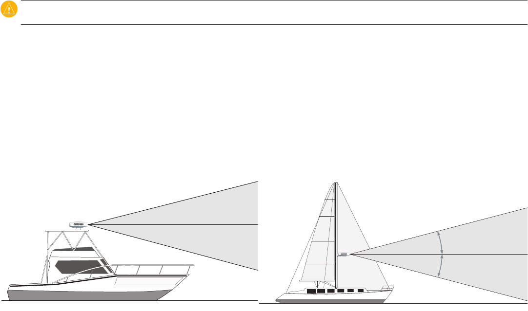
Mount other electronics and cables more than 7 ft. (2 m) from the path of a radar beam. A radar beam can spread 25° vertically above and
below the radiating element of the radar. For vessels with higher bow angles at cruise speed,you can lower the angle so that the beam points
slightly downward to the waterline while at rest. Shims may be used as necessary.
Install the radar away from antennas or other electronics. GPS antennas should be located above or below the radar beam path of the radar.
Mount at least 3 ft. (1 m) from any equipment transmitting or cables carrying radio signals, such as VHF radios, cables, and antennas. In the
case of SSB radios, the distance should be increased to 7 ft. (2 m).
12.5°
12.5°
12.5°
12.5°
•
•
•
•
•
◦
◦
◦
◦
•
◦
◦
•
•
GMR 600/1200 Series Installation Instructions 3
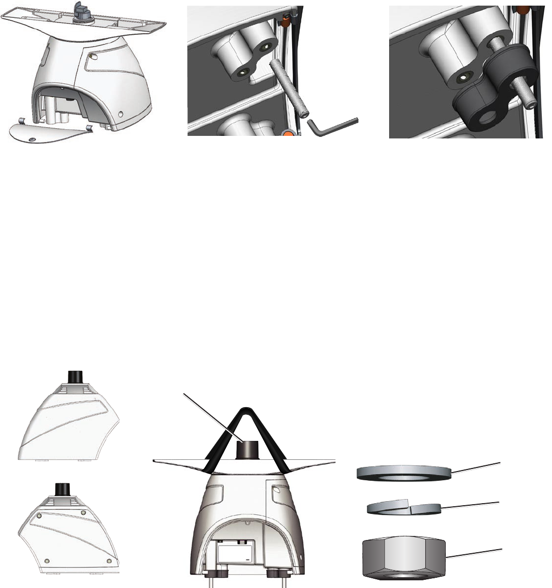
Installing the Mounting Studs and Seals
1. Remove the hatch on the front of pedestal by loosening the screw and lifting the hatch off of the hinges as shown in Figure 1.
2. Use a 5 mm Allen wrench, to install the M10 x 71 mounting studs (Figure 2) in the pedestal matching the hole pattern that was selected.
Tighten the mounting studs until they bottom out in the pedestal. Do not overtighten the studs to avoid damaging the pedestal. The mounting
studs have a thread-locking patch applied at the factory.
Optional: Apply moisture-inhibitive grease or paste to the four studs prior to installation.
3. Install the seals onto the pedestal (Figure 3).
Figure 1 Figure 2 Figure 3
Mounting the Radar
Mount the radar with either end pointed toward the bow. Ensure it is mounted along the Bow-Stern Axis line indicated on the GMR
400/600/1200 Series Mounting Template. If the end with the hatch is pointed toward the bow, the Front of Boat Offset setting on the chartplotter
must be set to 180° (Figure 4). To adjust the Front of Boat Offset on the chartplotter, see page 7.
To mount the radar:
1. (Skip to step two if you are using a pre-drilled Garmin compatible Furuno® or Raymarine® mount.) Determine a suitable mounting location
and tape the Mounting Template in place. The Mounting Template has two hole patterns: Option A and Option B. Determine the most
appropriate patterns from the two patterns available on the Mounting Template (Option A or Option B). Use a 1/2 in. (13 mm) bit to drill the
four mounting holes.
2. Hoist the radar into position using the supplied strap. Position the strap over the ends of the antenna mount as shown in Figure 5. Ensure
that you position the strap as close to the radar as possible.
3. FastentheradartothemountingsurfaceusingtheM10hexnuts,springwashers,andatwashersintheordershowninFigure6.TheM10
nuts should be torqued to 130 lbf-in (11 lbf-ft) (1.5 kgf-m).
Figure 5 Figure 6
at washer
spring washer
M10 hex nut
Figure 4
Bow
Stern
Bearing Offset = 0°
Bearing Offset = 180°
Waveguide protective cover
4 GMR 600/1200 Series Installation Instructions
Mounting the Antenna
1. Remove the protective cover from the pedestal wave guide.
2. Verify that the antenna wave guide is aligned with the pedestal wave
guide. Slide the antenna onto the pedestal.
3. Secure the antenna to the pedestal using the 8 mm hex bolts and
spring washers. The 8 mm bolts should be torqued to 70 lbf-in
(6 lbf-ft) (.81 kgf-m).
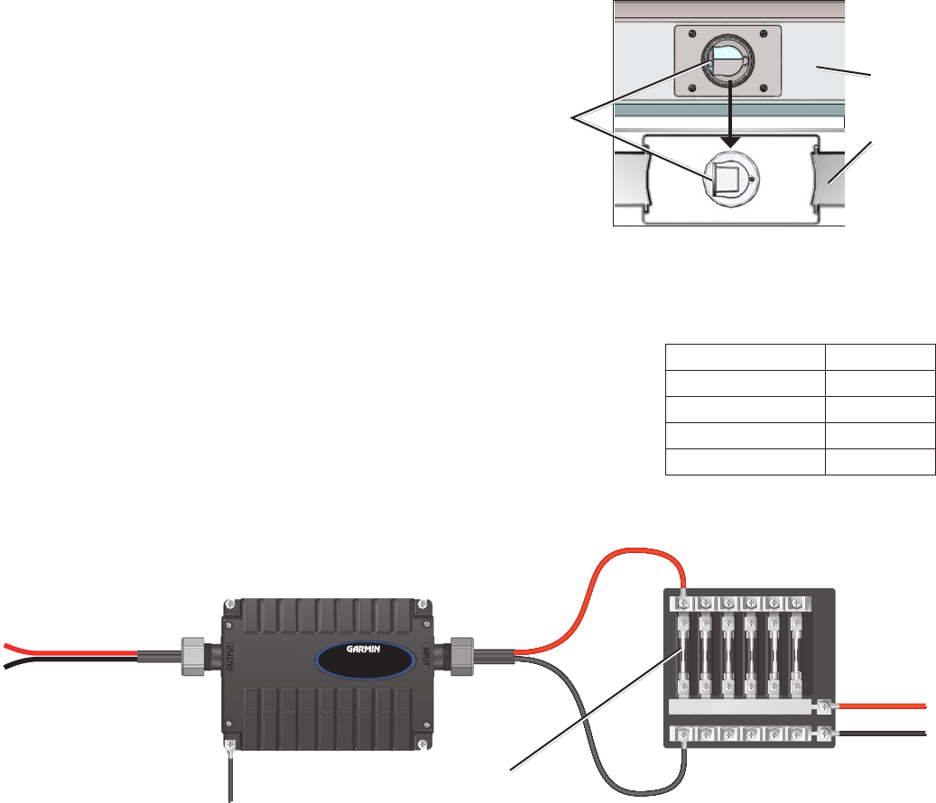
Installing the Voltage Converter Unit
The included voltage converter unit is needed to supply a specic constant voltage to the radar. When installing the voltage converter unit,
consider the following:
The voltage converter requires an input voltage of 10–40 Vdc (20–40 Vdc for the GMR 1204 and GMR 1206).
You must connect the converter to the boat battery through a 15 A slow-blow fuse.
Garmin recommends that you install the voltage converter as close as possible to the selected
power source.
For optimal performance, connect the voltage converter housing to the RF ground of the vessel.
If the input wires need to be extended, follow the recommendations in the wire gauge table.
If the wires are extended, use the supplied heat-shrink butt connectors.
After the connector is crimped, heat the connector to shrink it and provide a water resistant t.
Voltage Converter Unit
+
-
15 A slow-blow fuse
To radar
To RF ground
To power
10–40 Vdc
(20–40 Vdc for
the GMR 1204
and 1206)
GMR 600/1200 series
Voltage Converter Unit Sample boat fuse block
Connecting the Voltage Converter to a Boat Fuse Block
Installing the Power and Network Cables
Route the cable as needed, based on the type of mount you are using.
When installing the power and network cables, consider the following:
To ensure safety, use the appropriate tie-wraps, fasteners, and sealant to secure the cable along a route and through any bulkhead or deck.
Avoid running the cable near moving objects, high-heat sources, or through doorways and bilges.
Avoid installing the cable next to or parallel to other cables, such as radio antenna lines or power cables. This is essential to avoid
interference to or from other equipment. If this is not possible, shield the cable with metal conduit or a form of EMI shielding.
You may need to drill a 1
1
/
4
in. (31.7 mm) hole for routing the power/network cable. Garmin provides a rubber cable grommet to cover the
cable installation hole.
The grommet does NOT provide a waterproof seal. To waterproof the grommet, apply a marine sealant.
You can purchase additional cable grommets through Garmin or a Garmin dealer.
Use the optional eld-installable RJ-45 network connector (included) to create a custom-length Garmin Marine Network cable if needed
(see page 8).
•
•
•
•
•
◦
◦
•
•
•
◦
◦
•
Align the
waveguide faces
Antenna
Pedestal
Align the
waveguide faces
Antenna
Pedestal
Wire Gauge Table
Distance Gauge
9 ft. 10 in. (3 m) 12 AWG
16 ft. 4 in. (5 m) 10 AWG
21 ft. 3 in. (6.5 m) 9 AWG
26 ft. 2 in. (8 m) 8 AWG
Wire Gauge Table
Distance Gauge
9 ft. 10 in. (3 m) 12 AWG
16 ft. 4 in. (5 m) 10 AWG
21 ft. 3 in. (6.5 m) 9 AWG
26 ft. 2 in. (8 m) 8 AWG
GMR 600/1200 Series Installation Instructions 5
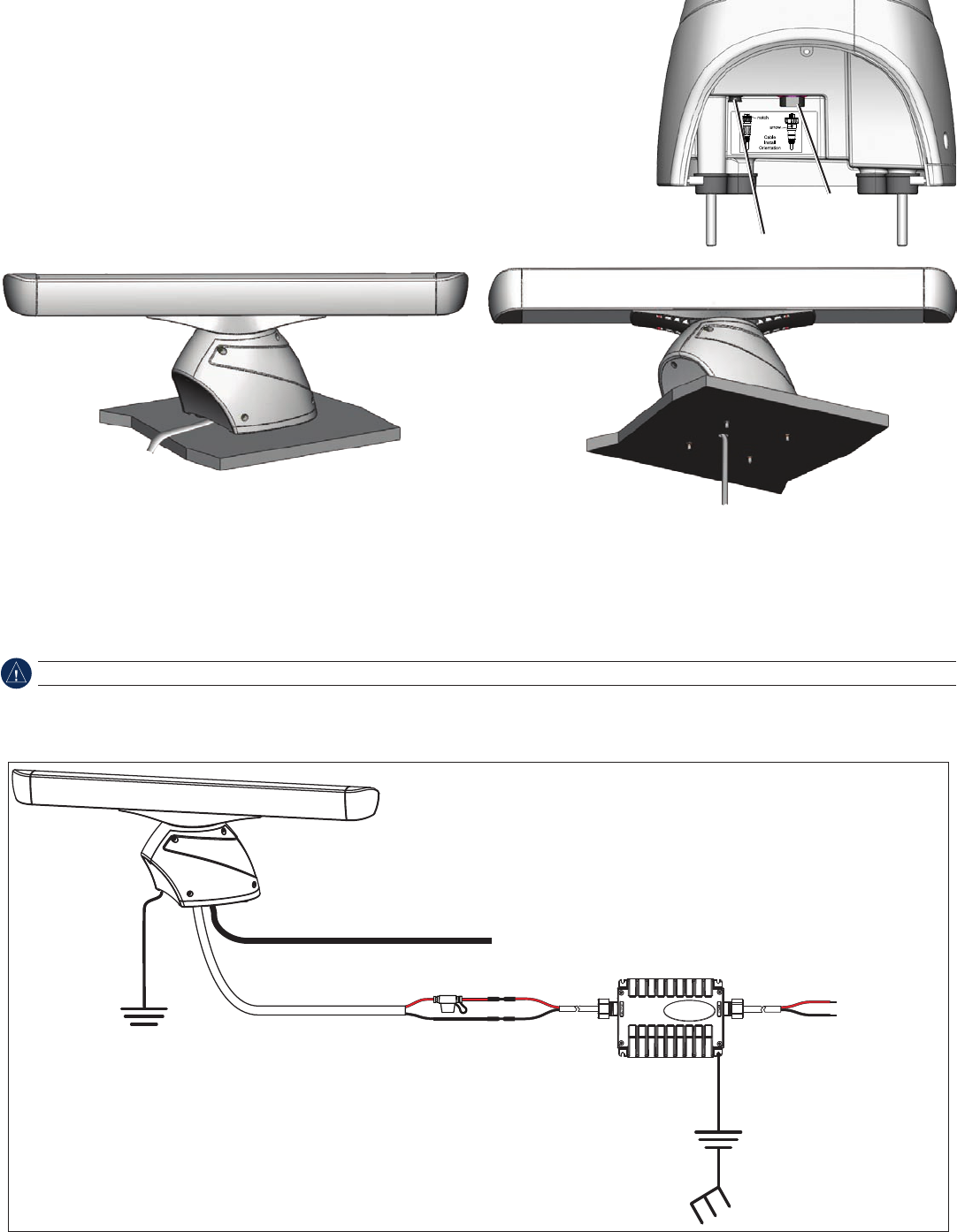
To install the cable assembly:
1. Align the notch and locking ring on the power cable to the power connector. Press the 2-pin
power cable to the power connector. Tighten the power-cable locking ring clockwise until it is
rmlysealed..
2. Press the RJ-45 marine network cable to the RJ-45 socket. Tighten the RJ-45 locking ring
clockwiseuntilitisrmlysealed.
3. Route the power and network cables through the front of the radar (Figure 7), or through a
hole drilled through the mounting surface (Figure 8). Avoid excessively bending or twisting the
cables.
4. Install the hatch on the front of the radar.
Figure 7 Figure 8
Connecting the Radar to Power Through the Voltage Converter
Connect the radar power cable (red and black) to the voltage converter output cable (red and black) using the supplied heat-shrink crimp
connectors. After crimping the connections, heat the connectors to shrink the housing for a water resistant t.
If you choose to cut the radar power cable, you must reconnect the in-line fuse holder.
Connect the radar to the water ground of the vessel using an 8 gauge copper cable (not included). Secure the ground wire to the radar housing
using one of the four mounting studs, an M10 nut, and at washer.
Power Wiring Diagram
10–40 Vdc
(20–40 Vdc for
the GMR 1204
and 1206)
+
-
Garmin marine network cable
Radar power cable
GMR 600/1200 series radar
Power converter
To RF ground
To water ground
7.5 A fuse
Power connector
RJ-45 network
cable connector
Power connector
RJ-45 network
cable connector
6 GMR 600/1200 Series Installation Instructions
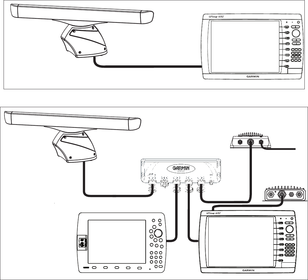
Connecting the Radar to the Garmin Marine Network
For a stand-alone network (chartplotter and radar only), attach the RJ-45 marine network cable to the RJ-45 socket on the back of the
chartplotter. For an expanded network (including a chartplotter, radar, a GMS 10, etc.), attach the RJ-45 marine network cable to an open RJ-45
socket on the GMS 10 network expander. Tighten the RJ-45 locking ring clockwise until it is rmly sealed.
GMR 600/1200 series
radar Garmin Marine Network-
compatible chartplotter
Stand-Alone Garmin Marine Network Example
Expanded Garmin Marine Network Example
x
x
x
x
x
x
x
x
xxx xxx xxx xxxxxx xxxx
Garmin
GPSMAP 4000/5000
series chartplotter
GSD 22 sounder unit
To transducer
Garmin
GPSMAP 3000 series
chartplotter
GMS 10 marine network port expander
GDL 30/30A
XM weather receiver
GMR 600/1200 series
radar
Each component of the expanded network must be installed according to its installation instructions. These diagrams only show how a
GMR 404/406 radar interacts with a network and do not show proper wiring for other network components.
Every device connected to the Garmin Marine Network must be connected to the power supply for the boat. These diagrams show the
network connections; however, they do not show the power connections. Wire each device according to the appropriate installation instructions.
GMR 600/1200 Series Installation Instructions 7
Conguring the Radar
After you install the radar, you must prepare the chartplotter or the Garmin Marine network to properly use the radar.
1. Update the chartplotter or Garmin Marine Network software.
2. Enter the radar antenna size.
3. Set the Front of Boat Offset if necessary.
Updating the Chartplotter or the Garmin Marine Network
If you have a GPSMAP 4000 or 5000 series chartplotter, use a blank SD card to update the chartplotter or the network according to the
instructions in the chartplotter owner’s manual.
If you have a GPSMAP 3000 series chartplotter, use a blank Garmin Data Card to update the chartplotter or the network according to the
instructions in the chartplotter owner’s manual.
Download the latest software from www.garmin.com.
Entering the Radar Antenna Size
Using a chartplotter, specify the size of your radar antenna (4 foot or 6 foot). Until you specify the antenna size, the warning “Radar Needs
Congured” appears on the chartplotter.
Ensure you specify the correct antenna size on your chartplotter to obtain optimum performance.
To enter the radar antenna size on a GPSMAP 4000 or 5000 series chartplotter:
1. From the Home screen, select Radar > Harbor (or Offshore).
2 From the Radar screen, select Menu > Radar Setup > Antenna Size.
3. Select the correct antenna size, 4 foot or 6 foot.
To enter the radar antenna size on a GPSMAP 3000 series chartplotter:
1. Press the PAGE key to switch to the Radar page.
2. Press the Setup softkey to open the setup page.
2. Using the ROCKER, highlight the Advanced tab, then the Antenna Sizeeld,andpressENTER.
3. Select the correct antenna size, 4 foot or 6 foot, and press ENTER.
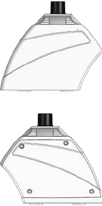
Changing the Front of Boat Offset
Depending on the radar installation, you may need to change the Front of Boat Offset. If the radar installation
requires a 180° offset, change the Front of Boat Offset to 180° and test the radar. If the Front of Boat Offset
needs further adjustment, measure the radar offset and change the offset using the following procedures.
To measure potential radar offset:
1. Using a magnetic compass, take an optical bearing of a stationary target located within viewable range.
2. Measure the target bearing on the radar.
3. If the bearing deviation is more than +/- 1°, further correct the Front of Boat Offset.
To change the Front of Boat Offset on a GPSMAP 4000 or 5000 series chartplotter:
1. From the Home screen, select Radar > Harbor (or Offshore).
2. From the Radar screen, select Radar Setup > Front of Boat.
3. Enter an offset value, then select Back.
To change the Front of Boat Offset:
1. From the Radar page, press the Setup softkey to open the setup page.
2. From the Setup page, using the ROCKER, select the Advanced tab.
3. Highlight the Front of Boat Offset slider, and press ENTER.
4. Adjust the value accordingly. The preview window changes as you adjust the slider.
5. After an offset is determined, press ENTER to save, and press QUIT to return to the Radar page.
bow
stern
Front of Boat Offset = 0°
Front of boat Offset = 180°
bow
stern
Front of Boat Offset = 0°
Front of boat Offset = 180°
8 GMR 600/1200 Series Installation Instructions
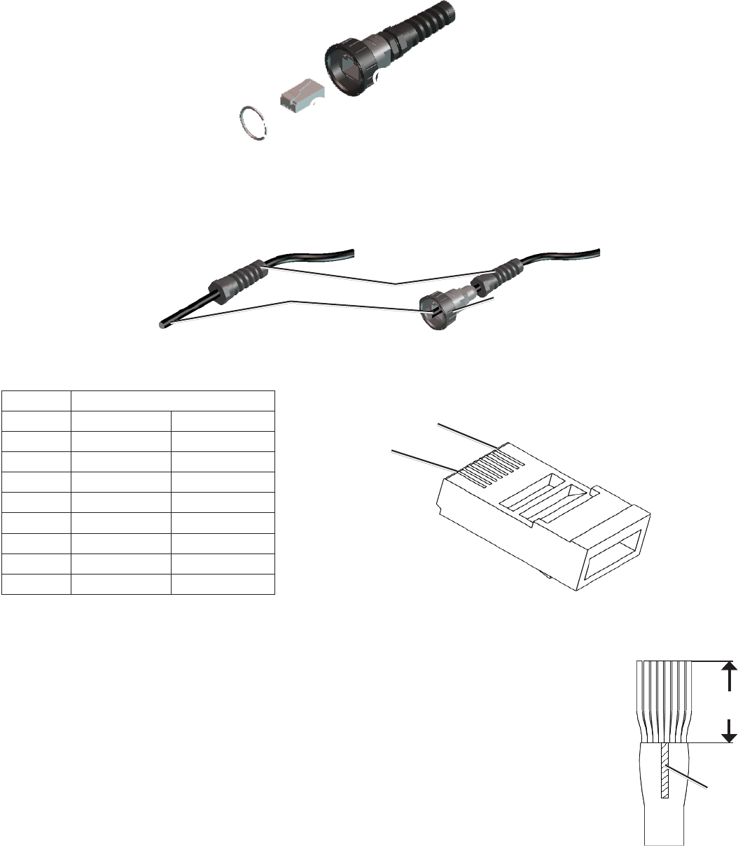
Installing the Field-Installable RJ-45 Network Connector (Optional)
A eld-installable RJ-45 network connector is provided for you to create a network cable that is the correct length for your installation.
➊
O-Ring
➋
RJ-45 modular plug
➌
Ethernet cable termination
Copper tape strip (not shown)
➊
➋
➌
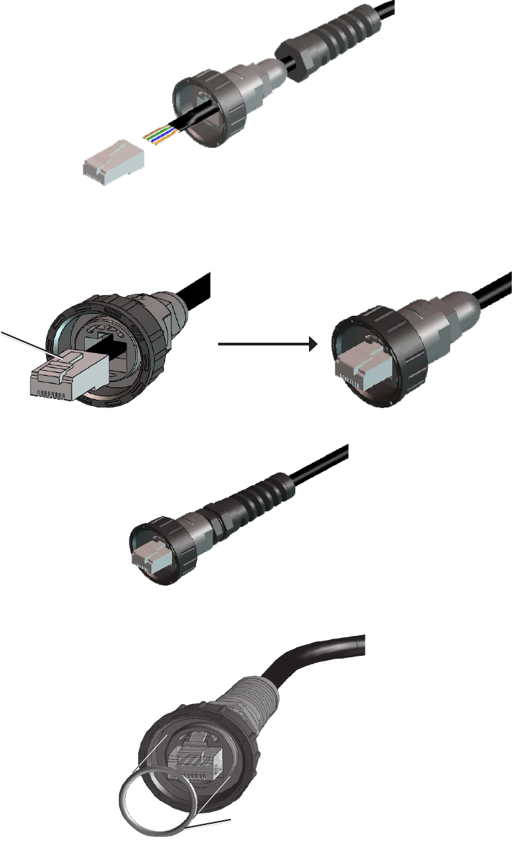
Preparing the Network Cable
1. Cleanly cut your Ethernet cable to the desired length. Retain the cut RJ-45 connector for Step 4.
2. Remove the strain-relief nut from the cable-connection housing and slide it onto the cut end of the cable as shown.
3. Feed the cut cable end through the connection housing as shown.
Strain relief
Cut end of cable Connection
housing
4. Examine the RJ-45 connector removed in Step 1 and compare it to the wire positions in the table below. Note which cable side, A or B, was
removed in Step 1.
Position Wire Color—Main/Stripe
Side A Side B
1 White/Orange White/Green
2 Orange Green
3 White/Green White/Orange
4 Blue Blue
5 White/Blue White/Blue
6 Green Orange
7 White/Brown White/Brown
8 Brown Brown
The Garmin Marine Network requires cross-over cables not exceeding 100 meters between devices. When constructing a custom cable
from bulk wire, you must create both a Side A and Side B.
5. Prepare the cable for plug installation:
Using a sharp knife, insert the blade between the cable shield and jacket. Slit the jacket 5/8" back from the
trimmed end of the cable.
Peel the jacket back and remove the slit portion.
TrimtheshieldandMylarlmawayfromwires.Becarefulnottocutanyofthewires.
Fold the drain wire back over the jacket and trim to approximately 9/16 iin. (14 mm).
Untwist the wire pairs enough to ensure a proper connection.
Arrangeindividualwiresinproperorderaccordingtothetableshownabove.Forexample,ifyouhaveidentied
the end of the cable in Step 4 as Side A, arrange the wires for Side A. If you are constructing a custom cable
from bulk wire, you need to make both a Side A and a Side B connection.
Trim the wire ends to an even length, leaving approximately 9/16 in. (14 mm) from the ends to the jacket edge.
Place the drain wire on the jacket. Wrap the supplied copper tape around cable as close to the edge of the jacket as possible.
Using a pair of pliers, squeeze the copper tape to pre-form the cable jacket end for easier insertion into the plug. Use caution to avoid
damaging the copper tape.
•
•
•
•
•
•
•
•
•
Position 1
Position 8
Position 1
Position 8
9
/
16
in.
(14 mm)
Drain
wire
9
/
16
in.
(14 mm)
Drain
wire
GMR 600/1200 Series Installation Instructions 9
Installing the Network Connector
1. Keeping the wires in proper sequence, insert them into the modular plug until the ends bottom out inside the plug. Visually inspect the wires
to verify proper order before continuing. If any wires are not in the correct position, remove the plug and rearrange the wires.
2. Using an AMP Modular Plug Hand Tool and Die Set (or compatible equivalent), crimp the plug onto the wires following the recommended
procedure of the crimp-tool manufacturer.
3. After the plug is crimped, align the release tab on the plug with the corresponding notch in the cable-connection housing. Depress the tab
and push the cable through the connection housing until the plug is securely seated in the plug cavity.
Release tab
4. Screw the strain relief nut onto the housing and tighten it snugly with a 15 mm wrench. Be careful not to overtighten the nut.
5. Install the O-ring onto the housing. The cable is now ready to use.
O-Ring
10 GMR 600/1200 Series Installation Instructions
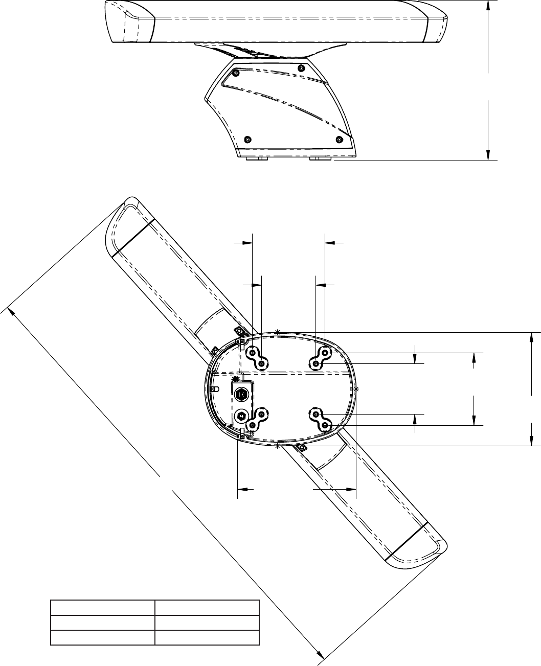
Unit Dimensions
Model L
GMR 604/1204 51
19
/
32
in. (1310 mm)
GMR 606/1206 75
45
/
64
in. (1923 mm)
17
11
/
32
in.
(440.8 mm)
7
7
/
8
in.
(200 mm)
5
29
/
32
in.
(150 mm)
5
33
/
64
in.
(140 mm)
7
7
/
8
in.
(200 mm)
12
11
/
32
in.
(313.5 mm)
12
7
/
8
in.
(326.8 mm)
L
GMR 600/1200 Series Installation Instructions 11
Specications
Pedestal (Physical)
42 lb. (19 kg)
49 ft. 2 35/64 in. (15 m) long
49 ft. 2 35/64 in. (15 m) long
600 Series
6 kW
9410 ±30 MHz
10–40 Vdc (with the Voltage
Converter Unit)
55 W
145 W max
0.125 – 0.5/75/3980
0.750 - 1/185/3975
1.5/235/3200
2.0/283/2750
3.0/370/1970
4.0/440/1736
6.0 – 12/535/1407
16 – 36/1032/800
48 – 72/1032/500
24 rpm and 48 rpm
100 kts
Less than 4 dB
from 14 to 140ºF
(from -10 to +60ºC)
95% at 95 ºF (35 ºC)
100 kn
Waterproof to IEC 60529 IPX6
65.5 ft. (20 m) mini, 72 nm max
65.5 ft. (20 m)
Anti-jamming algorithm
Sea clutter and rain clutter
1200 Series
12 kW
9410 ±30 MHz
20–40 Vdc (with the Voltage
Converter Unit)
65 W
155 W max
0.125 – 0.5/75/3980
0.750 - 1/185/3975
1.5/235/3200
2.0/283/2750
3.0/370/1970
4.0/440/1736
6.0 – 12/535/1407
16 – 36/1032/800
48 – 72/1032/500
24 rpm and 48 rpm
100 kts
Less than 4 dB
from 14 to 140ºF
(from -10 to +60ºC)
95% at 95 ºF (35 ºC)
100 kn
Waterproof to IEC 60529 IPX6
65.5 ft. (20 m) min, 72 nm max
65.5 ft. (20 m)
Anti-jamming algorithm
Sea clutter and rain
clutter
4 ft Open-Array Antenna
End-fed slotted waveguide
1.8 degrees
-23 dB within ±10 degrees of main
-30 dB outside ±10 degrees of main
24 degrees
29 dB
Horizontal
Better than -20 dB
12 lb. (5.4 kg)
6 ft. Open-Array Antenna
End-fed slotted waveguide
1.1 degrees
-25 dB within ±10 degrees of main
-30 dB outside ±10 degrees of main
24 degrees
30 dB
Horizontal
Better than -20 dB
16 lb. (7.3 kg)
Radar Display Features
North up, Course up,
Heading up
1 user adjustable (GPSMAP
4000/5000 series chartplotters)
2 user adjustable, capable of oating
(GPSMAP 3000 series chartplotters)
1 degree
65.5 ft. (20 m) or ±1.5%
of range scale, whichever is greater
Auto & manual gain adjust; manual or
auto (AFC) receiver tuning;
manual adjust for rain clutter and for sea
clutter.
Overlay mode is
supported. Also has split overlay with
standard radar presentation
Optimized radar performance in
the harbor
Optimized radar performance
offshore
Simultaneous operation of
two ranges displayed in split screen format
User selectable ranges of 1/8 nm to 3 nm on
left side and 1/8 nm to 72 nm on right side
(GPSMAP 3000 series
chartplotters) user-specied transmission and
standby time.
(GPSMAP 4000/5000 series
chartplotters) user-adjustable timed-transmit
mode
2x, 4x (GPSMAP 3000 series
chartplotters only)
Short, Medium, Long (GPSMAP
3000 series chartplotters only)
2 guard zones—user
adjustable
Look ahead (GPSMAP
4000/5000 series chartplotters)
Look ahead, Auto Shift and Manual
(GPSMAP 3000 series chartplotters)
Selectable to 24 or 48 rpm
Tracks up to 10 MARPA targets for
radar plotting and collision avoidance
(Heading sensor is required)

For the latest free software updates (excluding map data) throughout the life of your
Garmin products, visit the Garmin Web site at www.garmin.com.
© 2009 Garmin Ltd. or its subsidiaries
Garmin International, Inc.
1200 East 151st Street, Olathe, Kansas 66062, USA
Garmin (Europe) Ltd.
Liberty House, Hounsdown Business Park, Southampton, Hampshire, SO40 9LR UK
Garmin Corporation
No. 68, Jangshu 2nd Road, Shijr, Taipei County, Taiwan
www.garmin.com
May 2009 Part Number 190-01067-02 Rev. A Printed in Taiwan
All rights reserved. Except as expressly provided herein, no part of this manual may be reproduced, copied, transmitted, disseminated, downloaded or stored in any storage
medium, for any purpose without the express prior written consent of Garmin. Garmin hereby grants permission to download a single copy of this manual onto a hard drive or
other electronic storage medium to be viewed and to print one copy of this manual or of any revision hereto, provided that such electronic or printed copy of this manual must
contain the complete text of this copyright notice and provided further that any unauthorized commercial distribution of this manual or any revision hereto is strictly prohibited.
Information in this document is subject to change without notice. Garmin reserves the right to change or improve its products and to make changes in the content without
obligation to notify any person or organization of such changes or improvements. Visit the Garmin Web site (www.garmin.com) for current updates and supplemental
information concerning the use and operation of this and other Garmin products.
Garmin
®
, the Garmin logo, and GPSMAP
®
are trademarks of Garmin Ltd. or its subsidiaries, registered in the USA and other countries. GMR™ and myGarmin™ are
trademarks of Garmin Ltd. or its subsidiaries. These trademarks may not be used without the express permission of Garmin.
Furuno
®
is a registered trademark of Furuno Electric Co., Ltd. Raymarine
®
is a registered trademark of Raymarine Limited.