Garmin 01675 Marine Location Device User Manual
Garmin International Inc Marine Location Device
Garmin >
User Manual
®
February 2011 190-01243-02 Rev. B Printed in Taiwan
GDL 40–0110233910
The GDL 40 antenna provides GSM weather
data to compatible Garmin chartplotters on
your NMEA 2000 network. The GDL 40
communicates with nearby cellular towers
to receive weather data, purchased directly
from a Garmin chartplotter on a day-to-day
basis, as needed.
Contact Garmin Product Support if you have
any questions about this product.
• Go to www.garmin.com/support.
• Call (913) 397.8200 or (800) 800.1020.
Before installing the GDL 40 on your
boat, you must activate it online. During
the activation process, you must provide a
credit card that will be charged each time
you purchase a day-pass directly from the
chartplotter.
1. Record the unit ID and the serial number
(S/N) from your GDL 40 below.
The numbers are located on a sticker on
the antenna, and on the outside of the
package.
2. Go to http://my.garmin.com.
3. Complete an action:
• Sign in to your myGarmin account.
• If you do not have an existing
myGarmin account, create an
account.
4. Click the link to register your product.
5. Follow the on-screen instructions.
After you successfully register and
activate the antenna, you then purchase
a day-pass directly from the chartplotter
as needed.
Always wear safety goggles, ear protection,
and a dust mask when drilling, cutting, or
sanding. When drilling or cutting, always
check what is on the opposite side of the
surface.
Before installing your device, conrm
that your package includes the following
items. If any parts are missing, contact your
Garmin dealer immediately.
• GDL 40 antenna
• Surface-mount bracket
• Pole-mount bracket
• Under-deck-mount bracket
• Three M4 self-tapping screws
• M3 set screw
• NMEA 2000 T-connector
• NMEA 2000 drop cable
• Installation instructions, surface-mount
template, and registration sheet.
• Drill and drill bits
• Countersink bit—when mounting on
berglass
• Jigsaw—surface-mount hole
• Screwdriver—surface mount screws
• Marine sealant
• M4 self-tapping screws, shorter than 1 in.
(25 mm)—dependent on the thickness of
the surface in some under-deck-mounting
situations (page 4)
• Additional NMEA 2000 network
components (page 5)
• External cellular antenna, antenna cable,
and connector converter (page 5)
®
2 GDL 40 Installation Instructions
You can surface mount the GDL 40 antenna
(page 2), attach it to a standard marine pole
mount (page 3), or install the antenna under
berglass (page 4).
To ensure the best reception, keep these
considerations in mind while selecting a
mounting location.
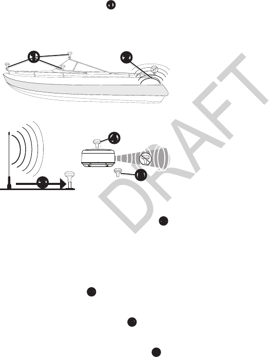
• Mount the antenna in a location that has
a clear, unobstructed view of the sky in
all directions.
• Mount the antenna where it is not
covered by the superstructure of the boat,
a radar device, or a mast
➊
.
• Higher mounting locations provide better
reception.
➎
➍
➌
➊➋
• Do not install the antenna near sources
of electromagnetic interference (EMI)
➋
,
such as the motor or other large marine
electronics.
• Install the antenna at least 3 ft. (1 m)
away from the path of a radar beam or
VHF radio antenna
➌
.
◦ It is best to install the antenna above
the path of the radar beam
➍
.
◦ It is acceptable to install the antenna
under the path of the radar beam
➎
.
• Install the antenna at least 5.9 in. (15 cm)
from a magnetic compass to avoid
interfering with the compass.
1. Select a mounting location (page 2).
2. Temporarily secure the antenna in the
selected location.
3. Test the antenna for correct operation on
the chartplotter.
4. If you experience interference with other
electronics, try a different location.
5. Repeat steps 3 and 4 until you nd a
mounting location where the antenna
operates correctly.
After you verify correct operation at the
mounting location, permanently mount the
antenna.
1. Select a mounting location for the
antenna, and verify correct operation at
the mounting location (page 2).
2. Trim the surface-mount template,
and make sure the antenna ts in the
mounting location you selected (page 2).
3. Remove the protective liner on the back
of the template, and apply the template
to the mounting location.
4. Use a
1
/
8
in. (3.2 mm) bit to drill the
three pilot holes indicated on the
template.
If you are mounting the antenna
on berglass, it is recommended to use
a countersink bit to drill a clearance
counterbore through the top gelcoat
layer (but no deeper). This helps to
avoid cracking in the gelcoat layer when
the screws are tightened.
5. Use a
3
/
8
in. (10 mm) bit to drill a starter
hole for the jigsaw blade, as indicated
on the template.
6. Use a jigsaw to cut the center hole as
indicated on the template.
GDL 40 Installation Instructions 3
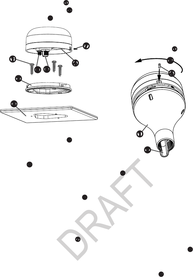
7. Use the three M4 screws
➊
to secure
the surface-mount bracket
➋
to the
mounting surface
➌
.
➏
➍
➎
➌
➊
➋
➐
8. Make sure the large gasket is in place on
the bottom of the antenna.
➍
9. Route a NMEA 2000 drop cable through
the center hole, and connect it to the
antenna
➎
.
10. If you are using an external cellular
antenna (page 5), route the antenna
cable through the center hole, and
connect it to the GDL 40 antenna
➏
.
11. Place the antenna on the surface-mount
bracket, and twist it clockwise to lock it
in place.
12. Secure the antenna to the mounting
bracket with the M3 set screw
➐
.
13. Route the NMEA 2000 drop cable away
from sources of electronic interference.
14. Connect the antenna to your NMEA
2000 network (page 5).
Using the pole-mount bracket, you can
install the antenna on a standard marine pole
mount (not included). A standard threaded
marine pole mount has the following
characteristics:
• An outer diameter (OD) of 1 inch
• Threads that measure 14 threads per inch
An external cellular antenna is not
compatible with the pole-mount bracket
(page 5).
1. Select a mounting location for the
antenna, and verify correct operation at
the mounting location (page 2).
2. Route a NMEA 2000 drop cable through
the pole-mount bracket
➊
.
➌
➊
➋
➍
3. Place the cable in the vertical slot
➋
along the base of the pole-mount
bracket.
4. Thread the pole-mount bracket onto
a standard marine pole mount (not
included).
Do not overtighten the bracket.
5.Connect the NMEA 2000 drop cable to
the antenna.
6. Place the antenna on the pole-mount
bracket, and twist it clockwise
➌
to lock
it in place.
7. Secure the antenna to the bracket with
the M3 set screw
➍
.
8. Fasten the marine pole mount to the boat
if it is not already attached.
9. Route the NMEA 2000 drop cable away
from sources of electronic interference.
10. Connect the antenna to your NMEA
2000 network (page 5).
11. After the antenna has been installed on
the pole mount, ll the remaining gap
in the vertical cable slot with a marine
sealant (optional).
4 GDL 40 Installation Instructions
1. Select a mounting location for the
antenna, and verify correct operation at
the mounting location (page 2).
2. Temporarily position a standard marine
pole mount (not included) in the
mounting location you selected (page 2).
3. Mark the approximate center of the pole.
4. At the marked location, use a
3
/
4
in.
(19 mm) bit to drill a hole for the cable
to pass through.
5. Fasten the marine pole mount to the boat
(hardware not included).
6. Thread the pole-mount bracket
➊
onto
the marine pole mount.
Do not overtighten the bracket.
7. Route a NMEA 2000 drop cable through
the pole-mount bracket and the pole, and
connect the cable to the antenna.
8. Place the antenna on the pole-mount
bracket, and twist it clockwise
➌
to lock
it in place.
9. Secure the antenna to the bracket with
the included M3 set screw
➍
.
10. Route the NMEA 2000 drop cable away
from sources of electronic interference.
11. Connect the antenna to your NMEA
2000 network (page 5).
12. After the antenna is installed on the pole
mount, ll the vertical cable slot with a
marine sealant (optional).
NOTICE
When choosing a location to install the
under-deck-mounting bracket, make sure
the included screws are not too long for
the surface thickness. If the screws are not
appropriate for the surface, you must supply
the correct length of M4 screws to avoid
damage to the top of the mounting surface.
The antenna can be mounted under a
berglass surface. Because the antenna has
difculty acquiring cellular signals through
metal, it is recommended that you use the
under-deck mount under a berglass surface.
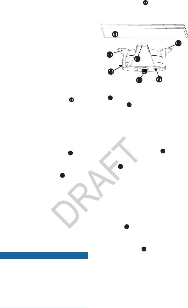
1. Identify the mounting location on the
berglass surface
➊
, and verify correct
operation at the mounting location
(page 2).
➌
➊
➋
➐
➎
➏
➍
2. Using the under-deck-mounting bracket
➋
as a template, mark three pilot-hole
locations
➌
on the surface.
3. Use a
1
/
8
in. (3.2 mm) bit to drill the
three marked pilot holes.
4. Place the antenna in the bracket, and
twist it clockwise to lock it in place.
6. Secure the antenna to the bracket with
the included M3 set screw
➍
.
7. Remove the backing from the adhesive
pads
➎
on the under-deck mounting
bracket.
8. Make sure that the bracket aligns with
the pilot holes, and adhere the under-
deck mounting bracket to the surface.
9. Using screws of the appropriate length,
fasten the bracket to the surface.
10. Connect a NMEA 2000 drop cable to the
antenna
➏
.
11. If you are using an external cellular
antenna (page 5), connect it to the
GDL 40 antenna
➐
.
12. Route the NMEA 2000 drop cable away
from sources of electronic interference.
13. Connect the antenna to your
NMEA 2000 network (page 5).

GDL 40 Installation Instructions 5
If you are unfamiliar with NMEA 2000, see
the “NMEA 2000 Network Fundamentals”
chapter of the Technical Reference for
Garmin NMEA 2000 Products for more
information. Go to www.garmin.com
/garmin/cms/us/onthewater/nmea2000, and
click .
1. Create a NMEA 2000 network on your
boat, if you do not have one.
You can purchase required cables and
connectors from www.garmin.com
/marine or your local marine dealer.
2. Connect the antenna to your
NMEA 2000 network using the
NMEA 2000 drop cable and a
T-connector.
If the included 19.5 ft. (6 m) drop cable
is not long enough, add an extension to
your NMEA 2000 backbone, based on
the NMEA 2000 guidelines.
NOTE: If you have not already
registered your GDL 40 (page 1),
you must power-cycle the NMEA
2000 network after you complete the
registration process.
In some instances, you can increase the
reception range of your GDL 40 antenna
by connecting a certied external cellular
antenna (sold separately).
An external cellular antenna is not
compatible with the pole-mount bracket
(page 3).
• Digital Antenna 295-PW (18" white
multiband antenna)
• Digital Antenna 861-CW (30" white
multiband antenna)
• Digital Antenna 861-CB (30" black
multiband antenna)
• Digital Antenna PowerMax™ cable, part
number DA240-30NM
• SubMiniature version A (SMA) male to
Mini UHF female RF connector adapter
◦ Bomar Interconnect part number
9316505
◦ Amphenol
®
Connex part number
242116
1. Mount the cellular antenna according to
the manufacturer’s instructions.
2. Connect the antenna cable to the
cellular antenna using the male Type N
connector.
3. Connect the SMA to Mini UHF adapter
to the Mini-UHF connector on the
antenna cable.
4 Connect the antenna cable (with the
adapter installed) to the SMA connector
on the bottom of the GDL 40.
After installing the GDL 40 antenna,
upgrade your Garmin chartplotter with the
latest software.
1. Go to www.garmin.com/support
/software/marine.html.
2. Select the update package that applies to
your network setup.
3. Follow the on-screen instructions.

6 GDL 40 Installation Instructions
Size Diameter × Height: 3
19
/
32
×
1
15
/
16
in. (91.6 × 49.5 mm)
Case Fully gasketed, high-impact
plastic alloy, waterproof to IEC
529 IPX7 standards
Temp. Range From 5°F to 151°F (from -15°C
to 70°C)
Compass Safe
Distance
5.9 in. (15 cm)
Power input
source
9–16 Vdc
Power usage 2.25 W max
NMEA
2000 Load
Equivalency
Number (LEN)
3 (150 mA)
059392 ISO Acknowledgment
060928 ISO Address Claim
126208 NMEA - Command/Request/
Acknowledge Group Function
126464 Transmit/Receive PGN List
Group Function
126992 System Time and Date
126996 Product Information
059392 ISO Acknowledgment
059904 ISO Request
060928 ISO Address Claim
126208 NMEA - Command/Request/
Acknowledge Group Function
The GDL 40 receives following weather
features, and provides them for display
on compatible Garmin chartplotters. The
weather features are broadcast in set
intervals, listed in the table.
City Forecasts Every 15 minutes
Satellite IR (Cloud Tops) Every 30 minutes
County Warnings Every 15 minutes
Hurricane Warnings Every 15 minutes
Lightning Every 15 minutes
Marine Warnings Every 15 minutes
Offshore Warnings Every 15 minutes
METARs Every 15 minutes
Weather Radar
(NEXRAD)
Every 15 minutes
Sea Surface Every 30 minutes
Weather Buoys Every 15 minutes
Winds Every 30 minutes
GDL 40 Installation Instructions 7
This product, its packaging, and its
components contain chemicals known to
the State of California to cause cancer,
birth defects, or reproductive harm. This
Notice is being provided in accordance
with California’s Proposition 65. If you
have any questions or would like additional
information, please refer to our Web site at
www.garmin.com/prop65.
NOTICE
The NMEA 2000 BUS that powers this
device must be protected by a 3A fuse to
avoid damage to the device.
This device complies with part 15 of the
FCC Rules. Operation is subject to the
following two conditions: (1) this device
may not cause harmful interference, and
(2) this device must accept any interference
received, including interference that may
cause undesired operation.
This product does not contain any user-
serviceable parts. Repairs should only
be made by an authorized service center.
Unauthorized repairs or modications
could result in permanent damage to the
equipment, and void your warranty and your
authority to operate this device under Part
15 regulations.
Category I radiocommunication devices
comply with Industry Canada Standard
RSS-210. Category II radiocommunication
devices comply with Industry Canada
Standard RSS-310.
This device complies with Industry Canada
licence-exempt RSS standard(s). Operation
is subject to the following two conditions:
(1) this device may not cause interference,
and (2) this device must accept any
interference, including interference that may
cause undesired operation of the device.
Le présent appareil est conforme aux CNR
d’Industrie Canada applicables aux appareils
radio exempts de licence. L’exploitation est
autorisée aux deux conditions suivantes: (1)
l’appareil ne doit pas produire de brouillage,
et (2) l’utilisateur de l’appareil doit accepter
tout brouillage radioélectrique subi,
même si le brouillage est susceptible d’en
compromettre le fonctionnement.
This equipment complies with FCC
radiation exposure limits set forth for an
uncontrolled environment. This equipment
should be installed and operated with
minimum distance of 7.9 in. (20 cm)
between the radiator and your body.
This transmitter must not be co-located or
operating in conjunction with any other
antenna or transmitter.
Hereby, Garmin, declares that this product is
in compliance with the essential
requirements and other
relevant provisions of
Directive 1999/5/EC. To view
the full Declaration of
Conformity, go to
www.garmin.com/compliance.
BY USING THE GDL 40, YOU AGREE
TO BE BOUND BY THE TERMS AND
CONDITIONS OF THE FOLLOWING
END USER SOFTWARE LICENSE
AGREEMENT. PLEASE READ
THIS AGREEMENT CAREFULLY
AND IF YOU DO NOT AGREE TO
THESE TERMS AND CONDITIONS,
RETURN THE COMPLETE PRODUCT
WITHIN 7 DAYS OF THE DATE YOU
ACQUIRED IT FOR A FULL REFUND
(IF PURCHASED NEW) TO THE ENTITY
FROM WHICH YOU PURCHASED THE
PRODUCT.
Garmin Ltd. and its subsidiaries (“Garmin”)
grant you a limited license to use the
software embedded in this device (the
“Software”) in binary executable form in
the normal operation of the product. Title,
ownership rights, and intellectual property
rights in and to the Software remain in
Garmin and/or its third-party providers.
You acknowledge that the Software is the
property of Garmin and/or its third-party
providers and is protected under the United
States of America copyright laws and

8 GDL 40 Installation Instructions
international copyright treaties. You further
acknowledge that the structure, organization,
and code of the Software, for which source
code is not provided, are valuable trade
secrets of Garmin and/or its third-party
providers and that the Software in source
code form remains a valuable trade secret
of Garmin and/or its third-party providers.
You agree not to decompile, disassemble,
modify, reverse assemble, reverse engineer,
or reduce to human readable form the
Software or any part thereof or create any
derivative works based on the Software. You
agree not to export or re-export the Software
to any country in violation of the export
control laws of the United States of America
or the export control laws of any other
applicable country.
Garmin licenses the weather data (“Weather
Data”) from Meteo France (“Meteo France”)
and provides you a license to the Weather
Data under this Agreement. The Weather
Data only indicates the measurement or
the most probable evolution of a set of
elements. You therefore acknowledge that
Garmin and Meteo France shall not be
liable for (i) the accuracy of the Weather
Data, whether the Weather Data is produced
by Meteo France or any of its third-party
providers, (ii) events that may result from
your interpretation and/or utilization,
directly or indirectly, of the Weather Data,
and/or (iii) the absence of observation data
in the case of absence or delay in availability
of Weather Data produced and owned by
national meteorological services (NMS), via
ECOMET or EUMETSAT, or via the Global
Transmission System (GTS). Accordingly,
you agree to refrain from pursuing claims
against Garmin, Meteo France or its third-
party providers for events relating to any
interpretation of the information contained
in the Weather Data or for missing data.
You acknowledge that you have been
fully informed of the restrictions of use of
the Weather Data, of the exclusions and/
or of the limitations of liability regarding
such Weather Data and of the date of
validity of the Weather Data provided and/
or displayed to you. The Weather Data is
provided on an “as is” basis, without any
warranties or conditions, express or implied,
including, but not limited to, any implied
warranty arising by law, statute, usage of
trade, or course of dealing. You assume all
responsibility and risk for the use of the
Software and the Weather Data and Garmin
and Meteo France disclaim all liability for
any loss, injury or damage, resulting from
the use of the Software and/or Weather
Data, whether direct or indirect, and whether
or not Garmin and/or Meteo France have
been advised of or has knowledge of the
possibility of such loss, injury or damage.
In no event shall Garmin or Meteo France
have any liability to you or any other
person or entity for any compensatory,
indirect, incidental, special, consequential or
exemplary damages whatsoever, including,
but not limited to, loss of revenue or prot,
or other commercial or economic loss,
even if Garmin or Meteo France have been
advised of the possibility of such damages,
or they are foreseeable. Specically
excluded from the license set forth in
this Agreement are uses or operations of
the Weather Data in connection with any
products, systems, applications or hardware
other than devices manufactured by or for
Garmin.
This Garmin product is warranted to be free
from defects in materials or workmanship
for one year from the date of purchase.
Within this period, Garmin will, at its sole
option, repair or replace any components
that fail in normal use. Such repairs or
replacement will be made at no charge to
the customer for parts or labor, provided
that the customer shall be responsible for
any transportation cost. This warranty
does not apply to: (i) cosmetic damage,
such as scratches, nicks and dents; (ii)
consumable parts, such as batteries, unless
product damage has occurred due to a
defect in materials or workmanship; (iii)
damage caused by accident, abuse, misuse,
water, ood, re, or other acts of nature
or external causes; (iv) damage caused by
service performed by anyone who is not
an authorized service provider of Garmin;
or (v) damage to a product that has been
modied or altered without the written
permission of Garmin. In addition, Garmin
reserves the right to refuse warranty claims
against products or services that are obtained
and/or used in contravention of the laws of
any country.

GDL 40 Installation Instructions 9
This product is intended to be used only as
a travel aid and must not be used for any
purpose requiring precise measurement of
direction, distance, location or topography.
Garmin makes no warranty as to the
accuracy or completeness of map data in this
product.
THE WARRANTIES AND REMEDIES
CONTAINED HEREIN ARE EXCLUSIVE
AND IN LIEU OF ALL OTHER
WARRANTIES EXPRESS, IMPLIED,
OR STATUTORY, INCLUDING ANY
LIABILITY ARISING UNDER ANY
WARRANTY OF MERCHANTABILITY
OR FITNESS FOR A PARTICULAR
PURPOSE, STATUTORY OR
OTHERWISE. THIS WARRANTY GIVES
YOU SPECIFIC LEGAL RIGHTS, WHICH
MAY VARY FROM STATE TO STATE.
IN NO EVENT SHALL GARMIN BE
LIABLE FOR ANY INCIDENTAL,
SPECIAL, INDIRECT, OR
CONSEQUENTIAL DAMAGES,
WHETHER RESULTING FROM THE
USE, MISUSE, OR INABILITY TO USE
THIS PRODUCT OR FROM DEFECTS
IN THE PRODUCT. SOME STATES DO
NOT ALLOW THE EXCLUSION OF
INCIDENTAL OR CONSEQUENTIAL
DAMAGES, SO THE ABOVE
LIMITATIONS MAY NOT APPLY TO
YOU.
Garmin retains the exclusive right to
repair or replace (with a new or newly-
overhauled replacement product) the device
or software or offer a full refund of the
purchase price at its sole discretion. SUCH
REMEDY SHALL BE YOUR SOLE
AND EXCLUSIVE REMEDY FOR ANY
BREACH OF WARRANTY.
To obtain warranty service, contact your
local Garmin authorized dealer or call
Garmin Product Support for shipping
instructions and an RMA tracking number.
Securely pack the device and a copy of the
original sales receipt, which is required as
the proof of purchase for warranty repairs.
Write the tracking number clearly on the
outside of the package. Send the device,
freight charges prepaid, to any Garmin
warranty service station.
Products
purchased through online auctions are not
eligible for rebates or other special offers
from Garmin warranty coverage. Online
auction conrmations are not accepted for
warranty verication. To obtain warranty
service, an original or copy of the sales
receipt from the original retailer is required.
Garmin will not replace missing components
from any package purchased through an
online auction.
A separate
warranty may be provided by international
distributors for devices purchased outside
the United States depending on the country.
If applicable, this warranty is provided by
the local in-country distributor and this
distributor provides local service for your
device. Distributor warranties are only valid
in the area of intended distribution. Devices
purchased in the United States or Canada
must be returned to the Garmin service
center in the United Kingdom, the United
States, Canada, or Taiwan for service.
Garmin
®
, the Garmin logo, and GDL
®
are trademarks
of Garmin Ltd. or its subsidiaries, registered in the
USA and other countries. These trademarks may not
be used without the express permission of Garmin.
NMEA 2000
®
is a registered trademark of the National
Marine Electronics Association.
PowerMax™ is a trademark of Digital Antenna, Inc.
Amphenol
®
is a registered trademark of Amphenol
Corporation.

© 2011 Garmin Ltd. or its subsidiaries
Garmin International, Inc.
1200 East 151st Street, Olathe, Kansas 66062, USA
Garmin (Europe) Ltd.
Liberty House, Hounsdown Business Park, Southampton, Hampshire, SO40 9LR UK
Garmin Corporation
No. 68, Jangshu 2nd Road, Sijhih, Taipei County, Taiwan
www.garmin.com