Garmin 0181200 LICENSED NON-BROADCAST AERONAUTICAL TRANSMITTER User Manual 190 01277 00
Garmin International Inc LICENSED NON-BROADCAST AERONAUTICAL TRANSMITTER 190 01277 00
UserManual.wiki
>
Garmin
>
0181200 User Manual
User Manual
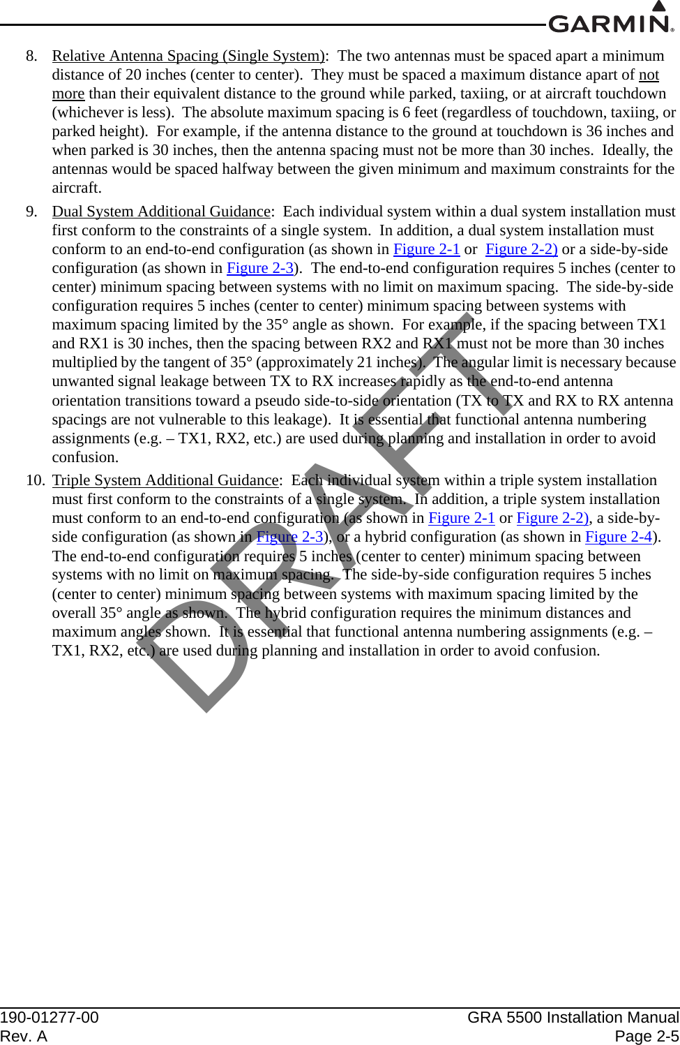
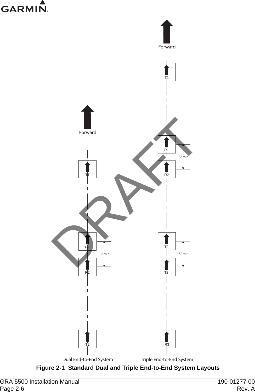
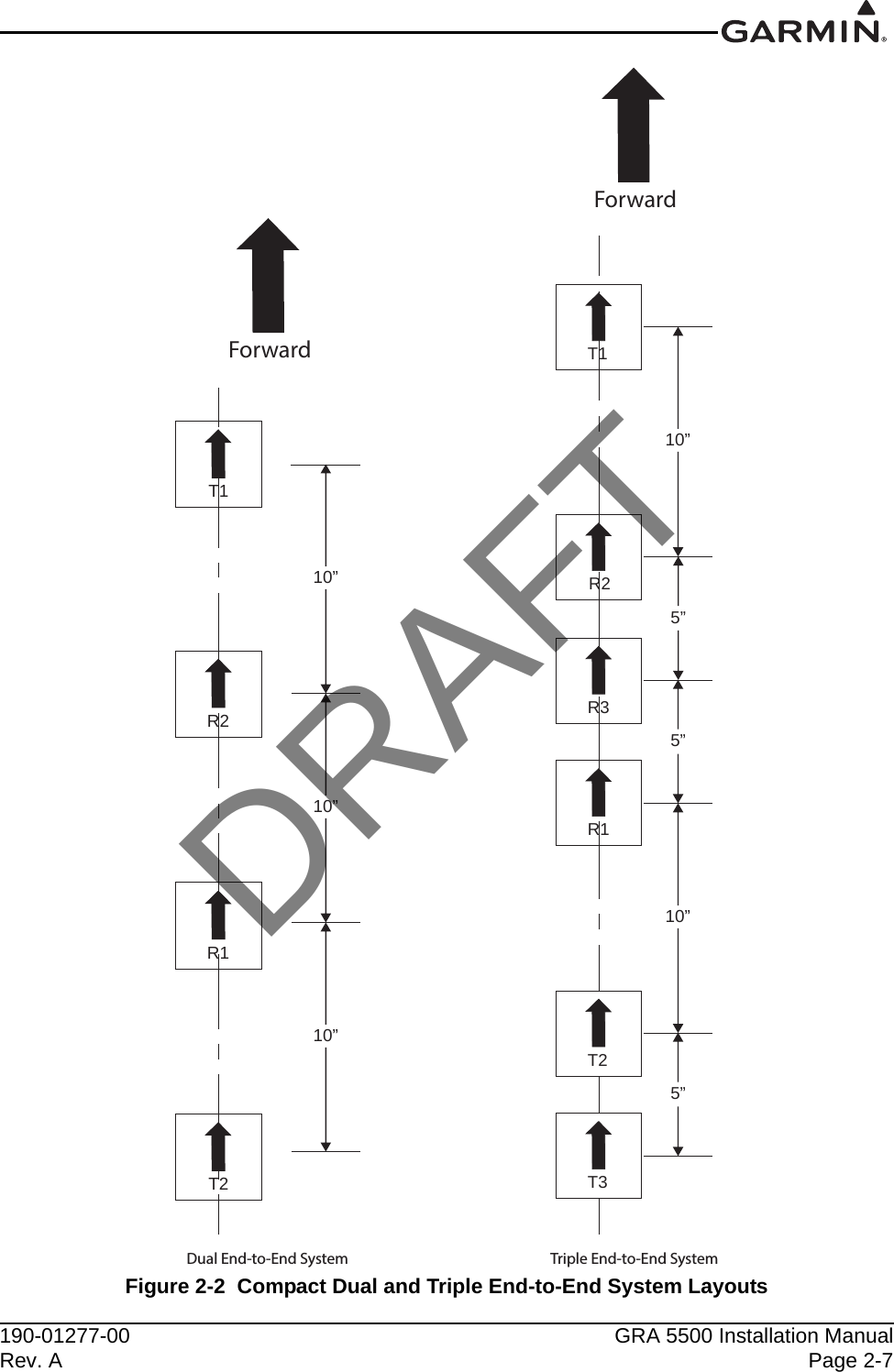
Navigation menu
Upload a User Manual
Namespaces
Wiki Guide
HTML
PDF
Info
Views
User Manual
Discussion / Help
Navigation
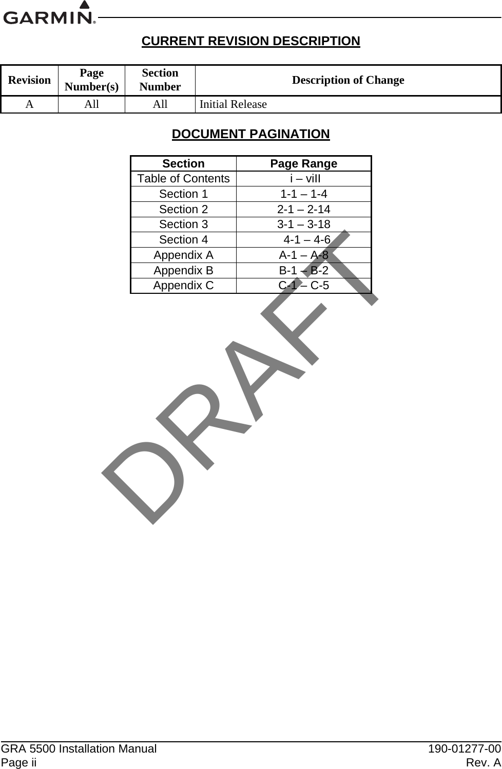

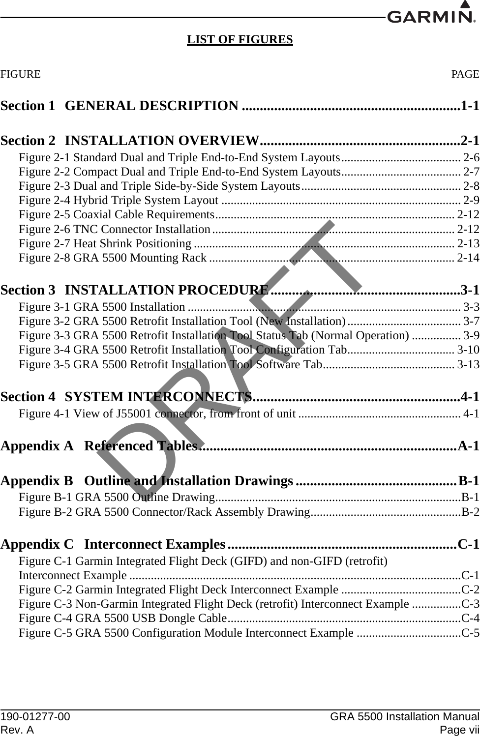
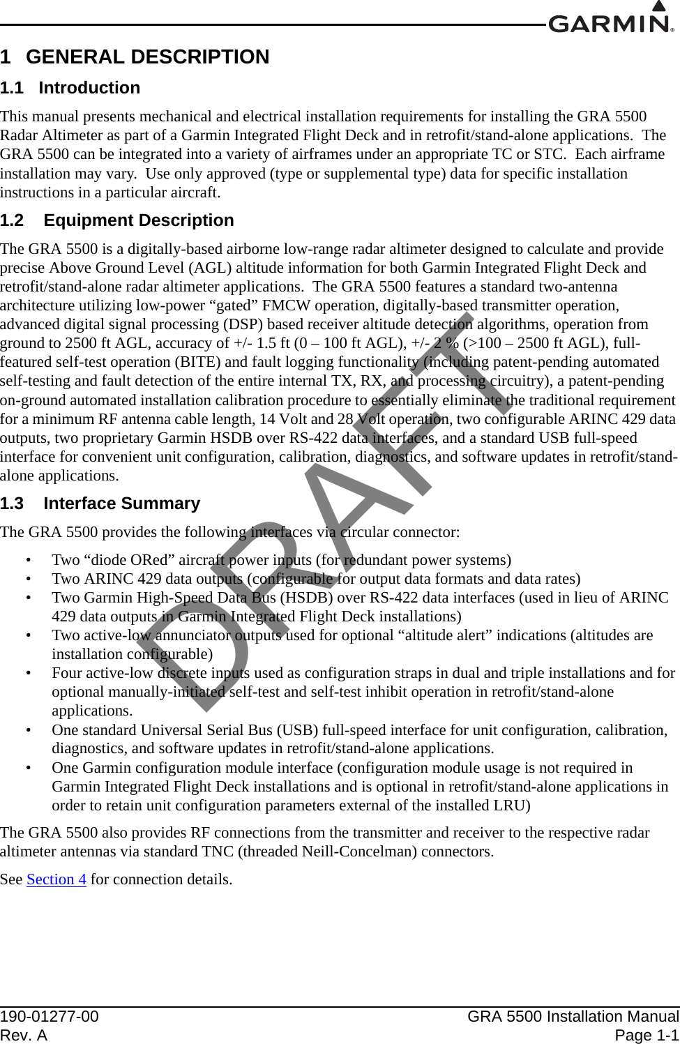
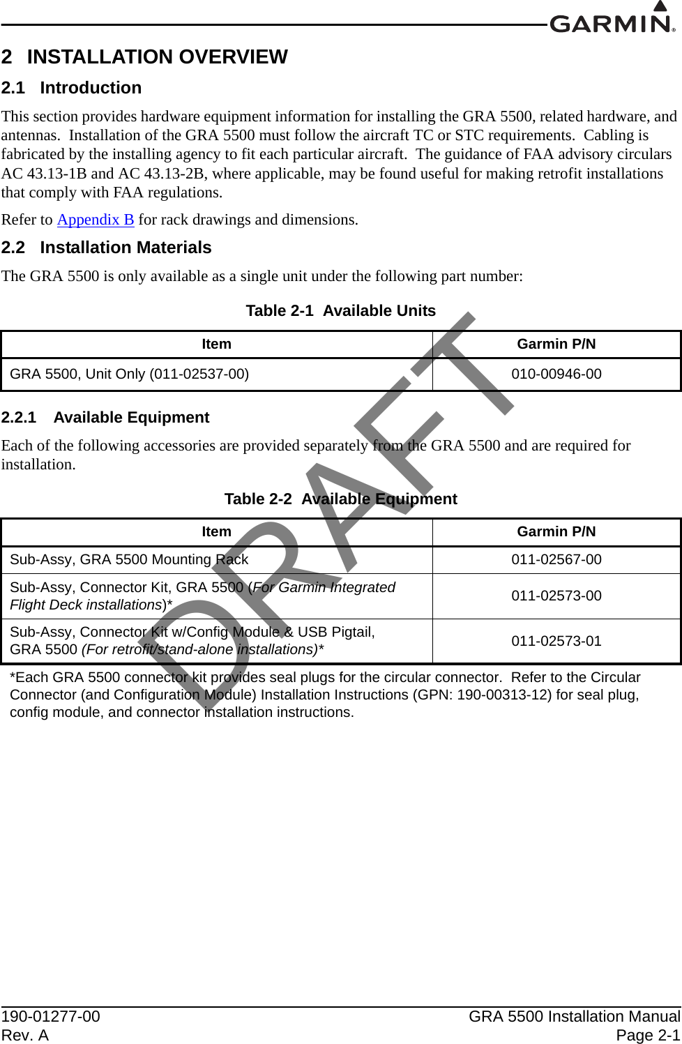
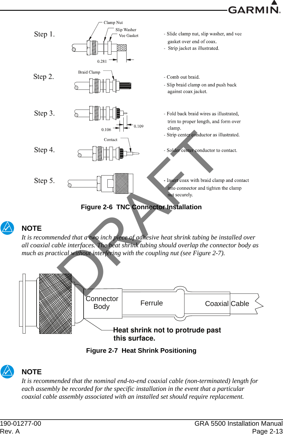
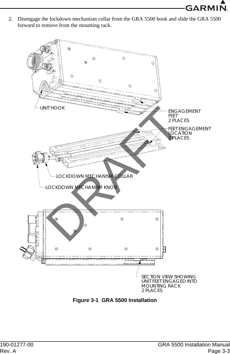
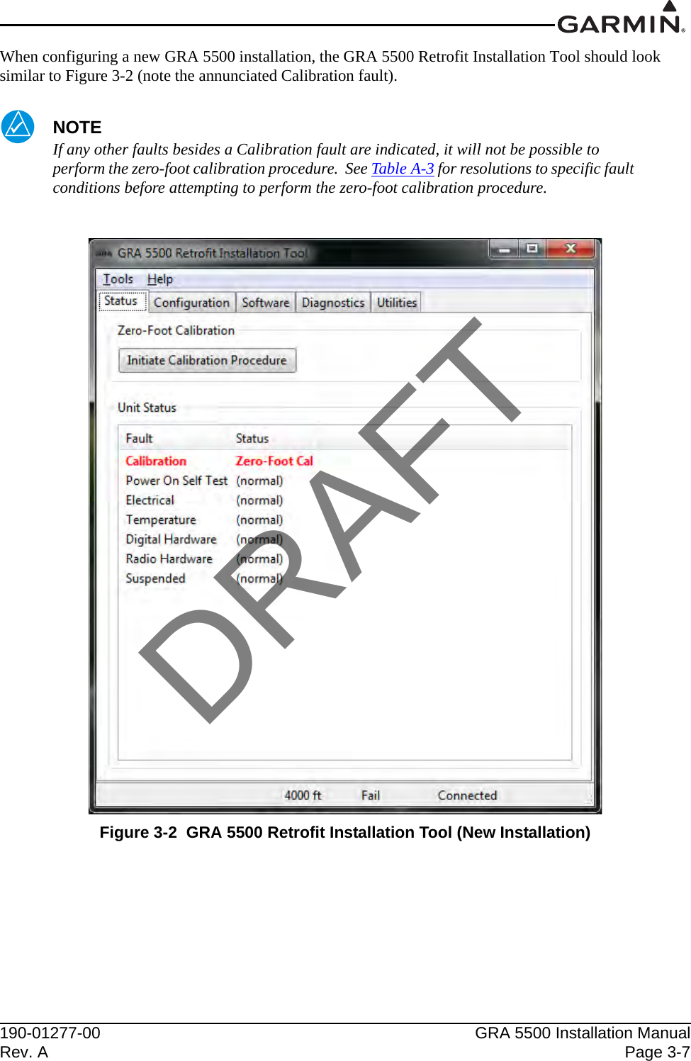
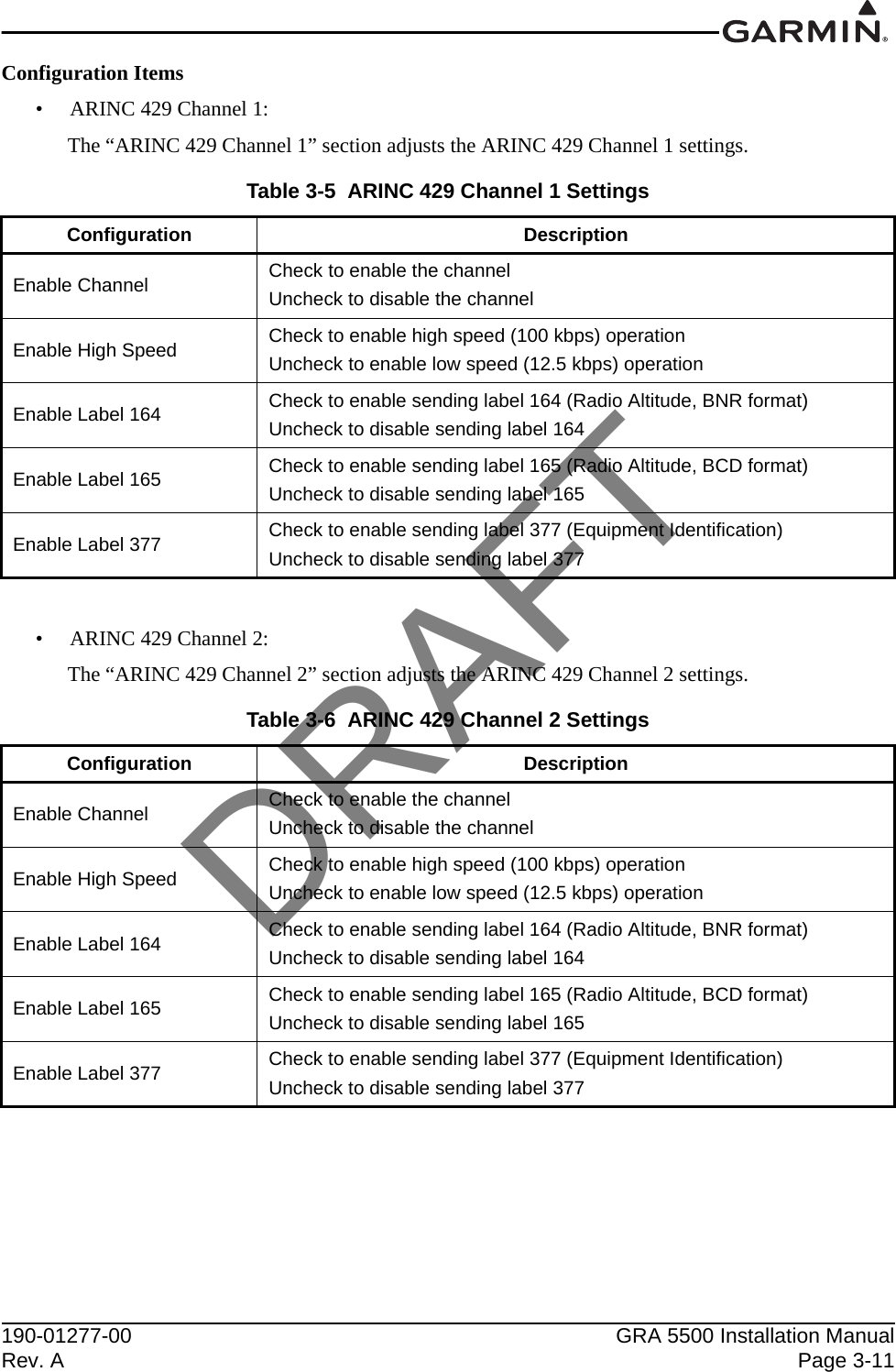
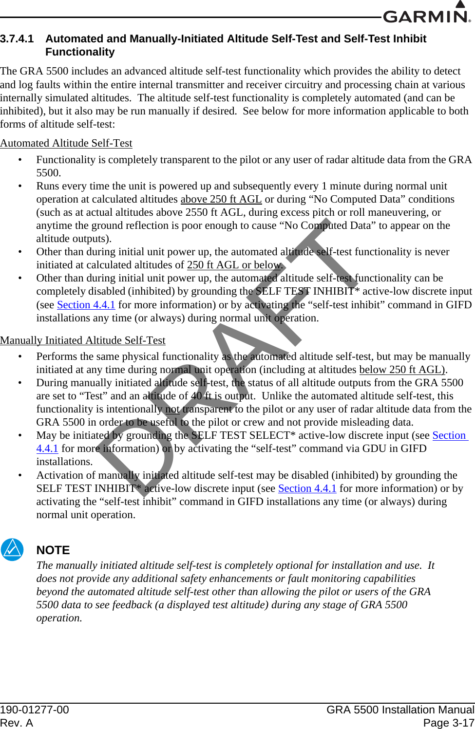
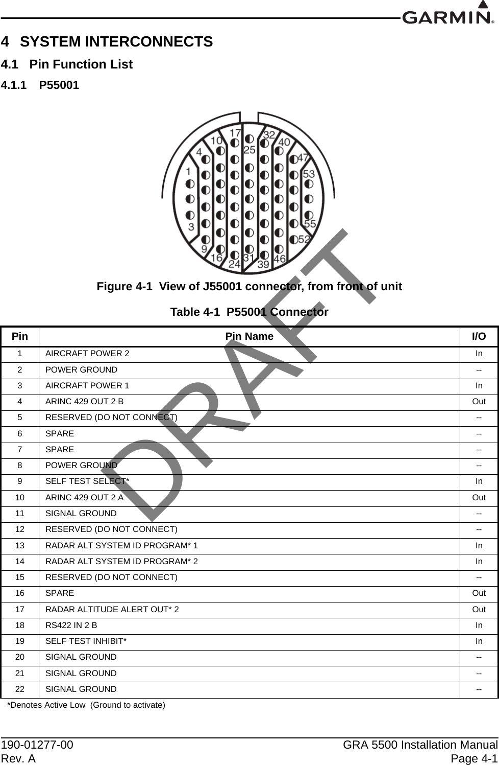
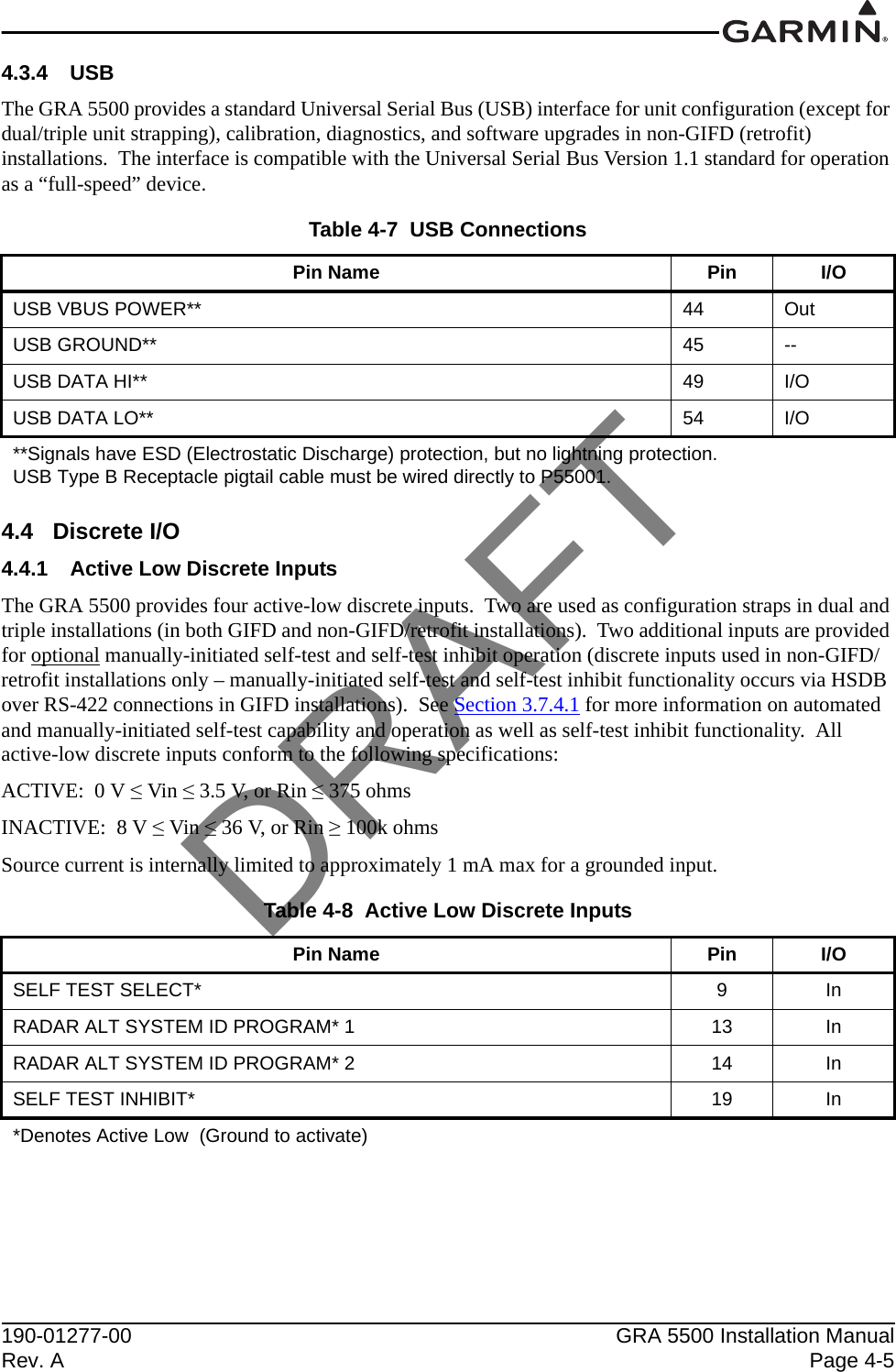
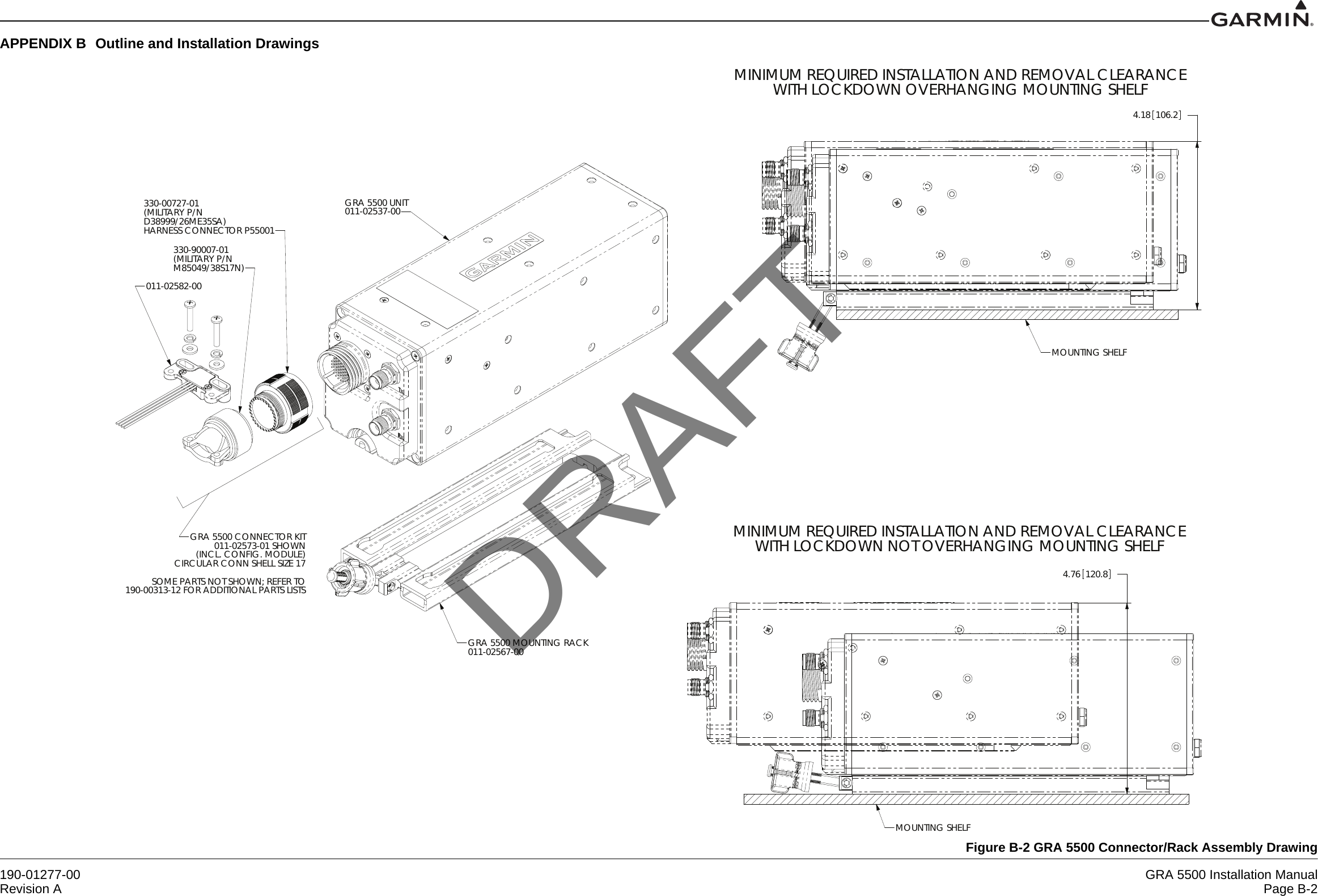
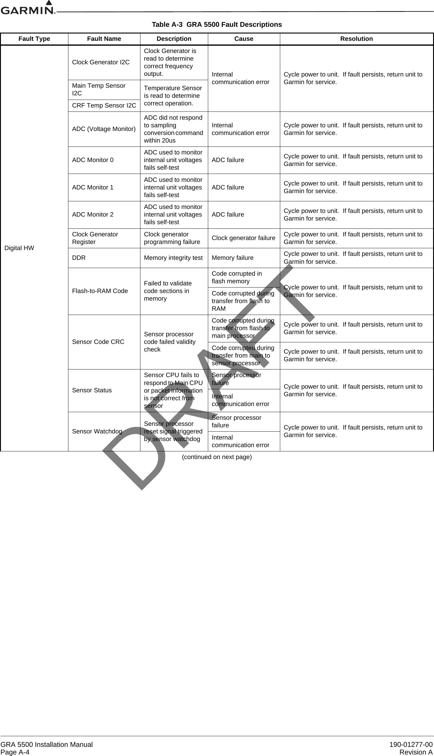
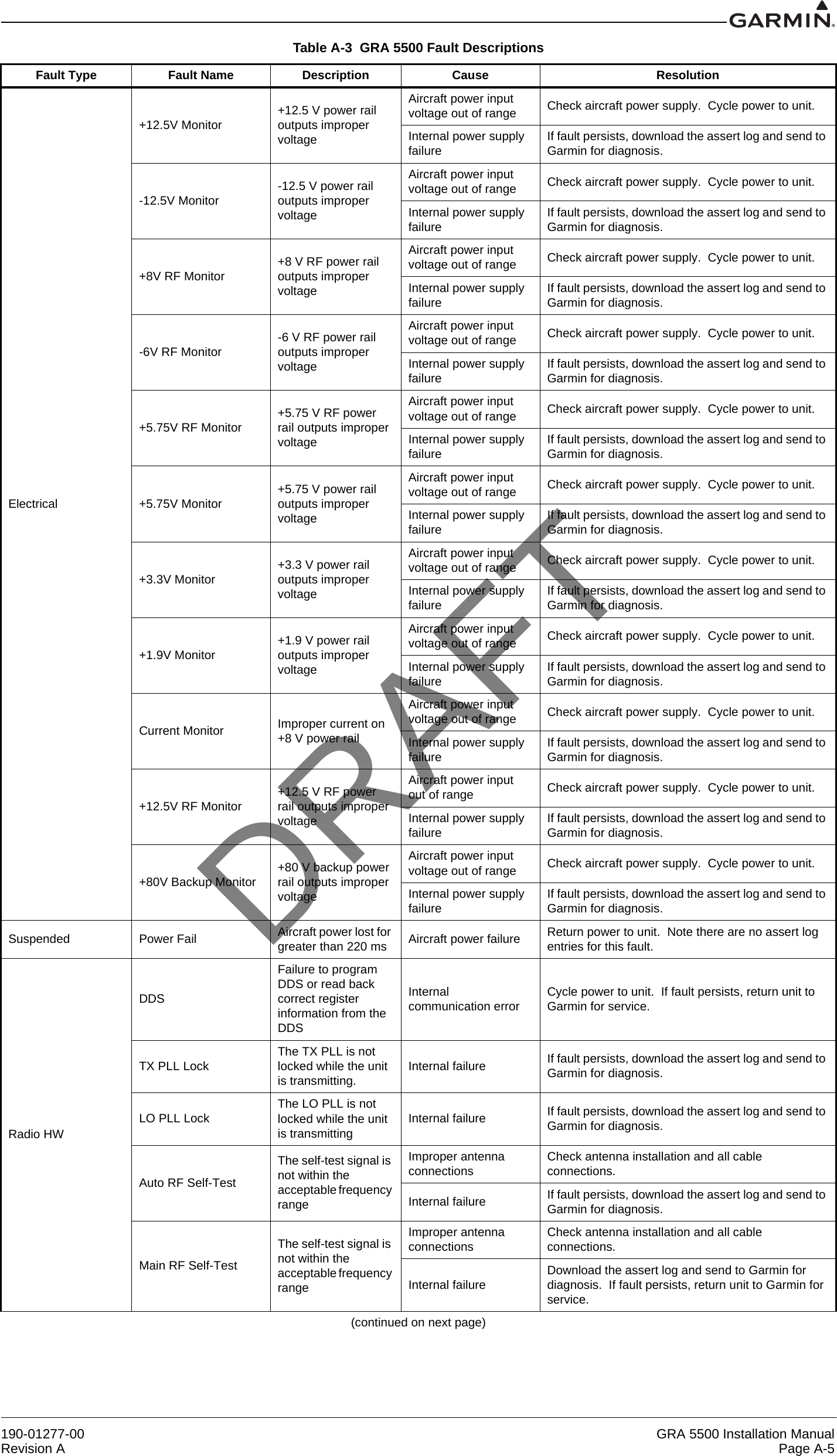
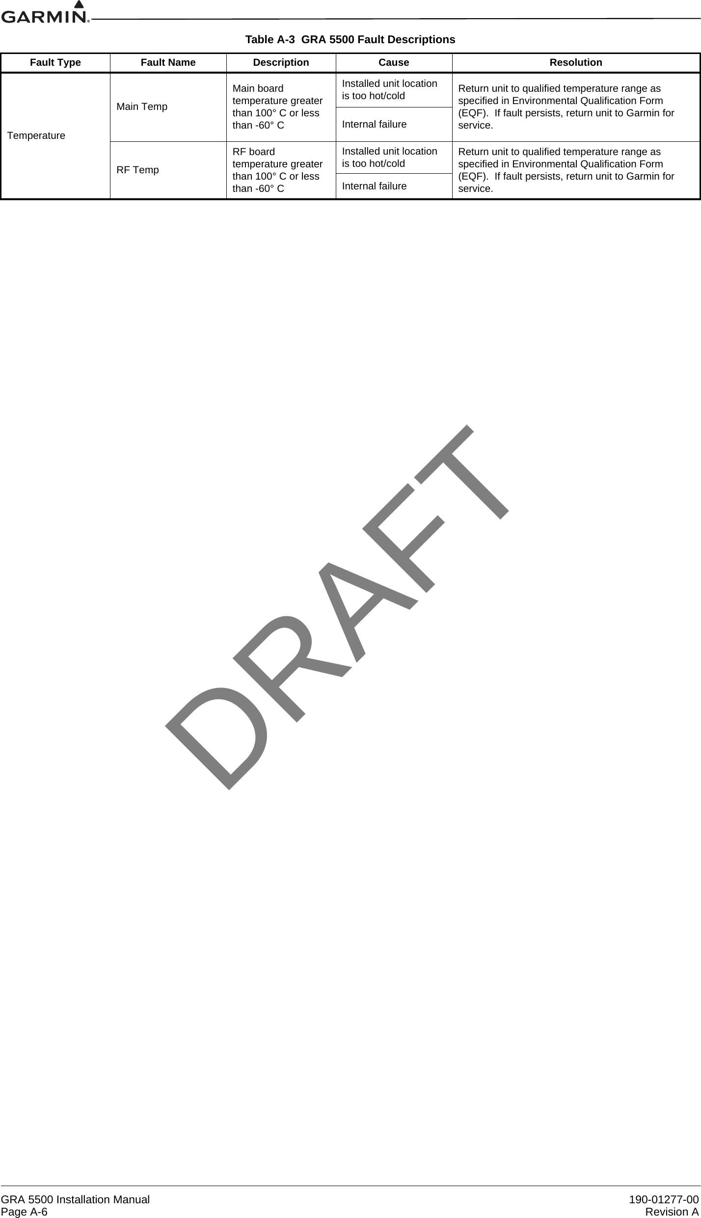
![190-01277-00 GRA 5500 Installation ManualRevision A Page A-1APPENDIX A Referenced TablesTable A-1 Recommended Coaxial LengthMin. & Max. Lengths (max. loss includes cable and connector loss combined) Max Cable Attenuation (dB/100ft) Carlisle IT Type1PIC Type2MIL-C-17 Type3RG Type4Minimum Maximum (loss of 5.0 dB)1' 0" [0.30m] 10' 0" [3.05m] 45.7 M17/128-RG400 RG-4001' 0" [0.30m] 10' 0" [3.05m] 45.6 M17/60-RG142 RG-1421' 0" [0.30m] 20' 0" [6.09m] 22.8 M17/127-RG3935RG-39351' 0" [0.30m] 14' 9" [4.49m]727.9 S882071' 0" [0.30m] 15' 3" [4.65m]731.8 3C142B1' 0" [0.30m] 15' 4" [4.76m]730.7 4321011' 0" [0.30m] 16' 7" [5.05m]727.5 S441911' 0" [0.30m] 17' 8" [5.38m]725.8 S441931' 0" [0.30m] 18' 0" [5.46m]726.4 3119011' 0" [0.30m] 18' 2" [5.54m]724.4 3520011' 0" [0.30m] 25' 6" [7.77m]718.4 3116011' 0" [0.30m] 26' 3" [7.62m]718.3 4216011' 0" [0.30m] 27' 3" [8.35m]716.3 S671631' 0" [0.30m] 29' 5" [8.96m]715.5 S331411' 0" [0.30m] 30' 0"6 [9.14m]714.7 3115011' 0" [0.30m] 30' 0"6 [9.14m] 13.0 4212011' 0" [0.30m] 30' 0"6 [9.14m] 11.8 S551221' 0" [0.30m] 30' 0"6 [9.14m] 11.8 3112011' 0" [0.30m] 30' 0"6 [9.14m] 8.3 S220891' 0" [0.30m] 30' 0"6 [9.14m] 7.8 3108011Vendor: Carlisle IT (Electronic Cable Specialists) 5300 W Franklin Drive, Franklin, WI 53132Telephone: 800.327.9473 or 414.421.5300, Fax: 414.421.5301 Website: www.carlisleit.com2Vendor: PIC Wire and Cable N53 W24747 S Corporate Circle, Sussex, WI 53089-0330 Telephone 800.742.3191 or 262.246.0500, Fax: 262.246.0450 Website: www.picwire.com3Except for RG393, see current issue of Qualified Products List, QPL-17.4RG types are obsolete and are shown for reference only; replaced by M17 type numbers.5RG393 is listed only for the purpose of re-using existing RG393 cable for retrofits.6Antenna cable length shall not exceed 30 feet per cable.7Calculation provided by cable manufacturerDRAFT](https://usermanual.wiki/Garmin/0181200/User-Guide-1885115-Page-54.png)
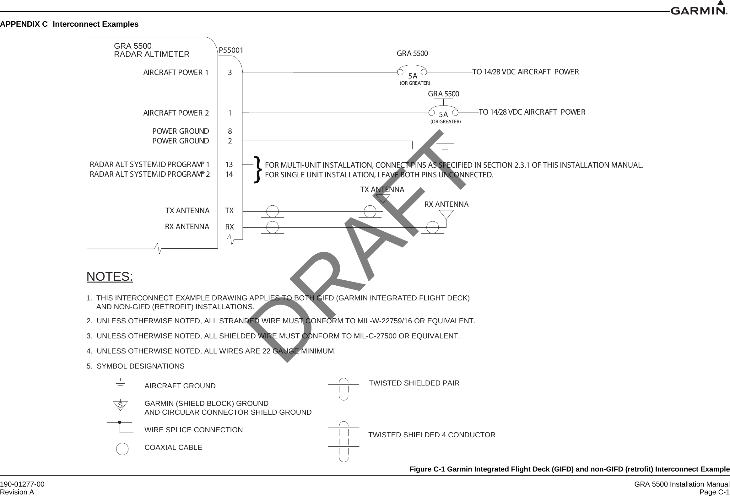
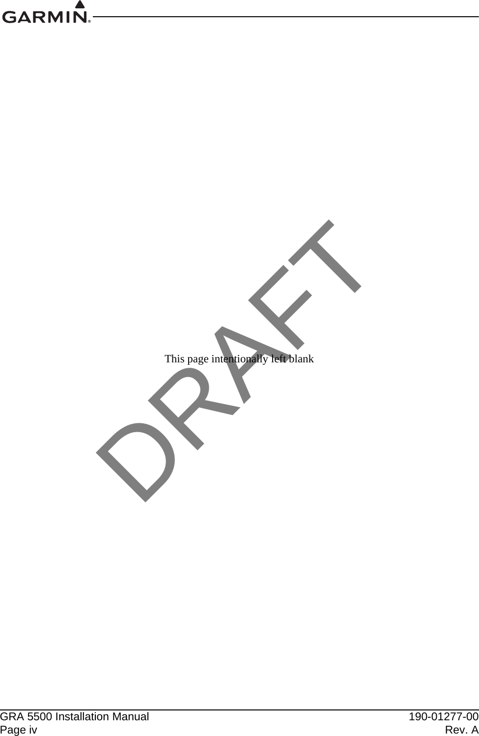
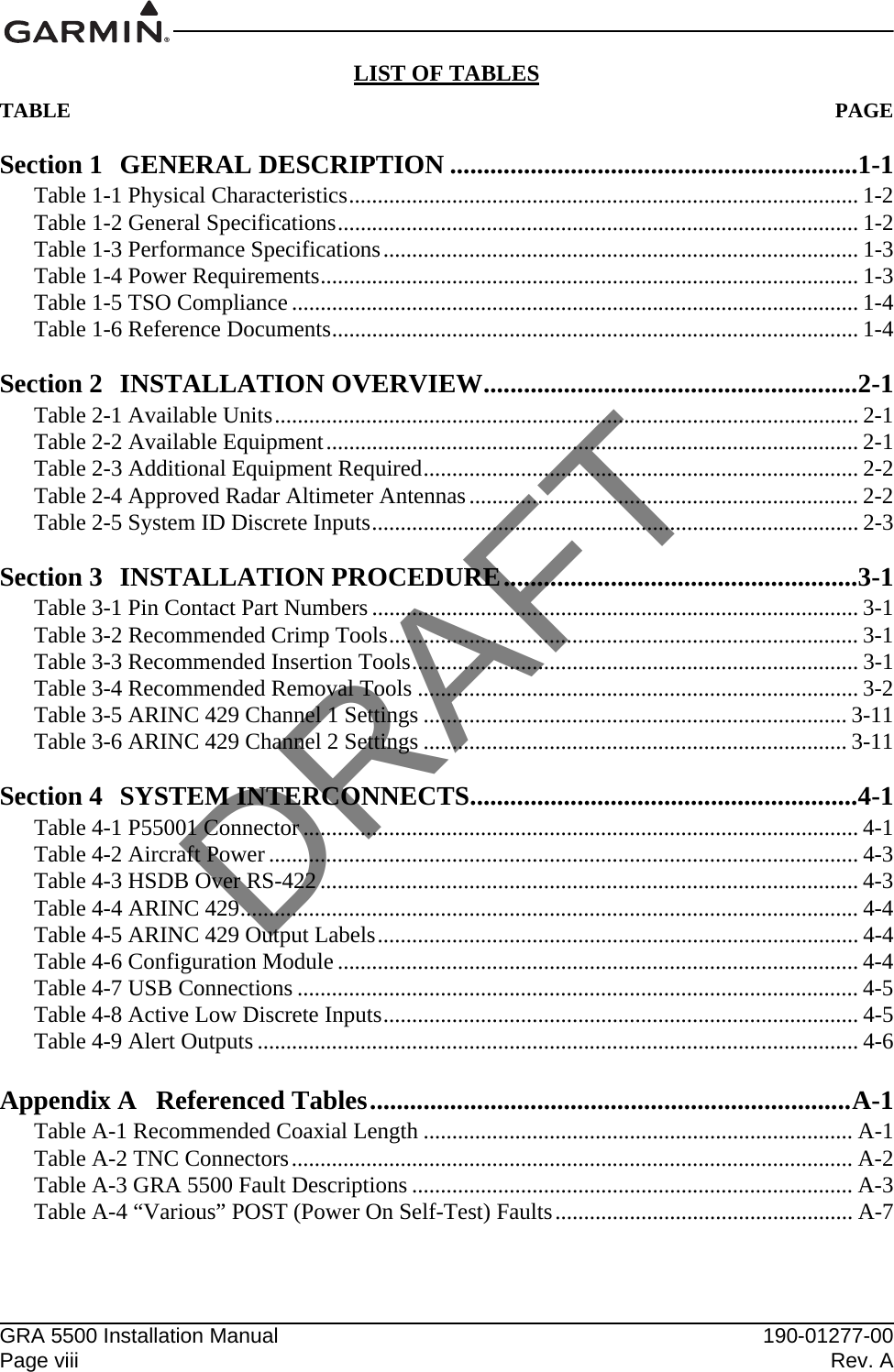
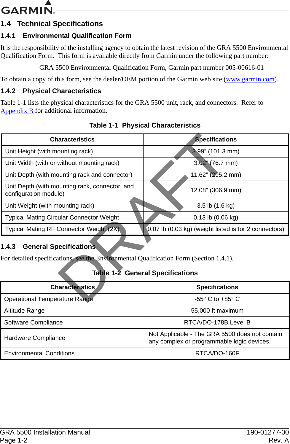
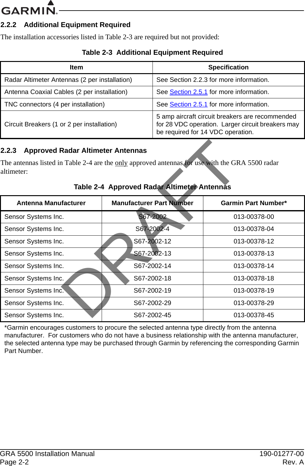
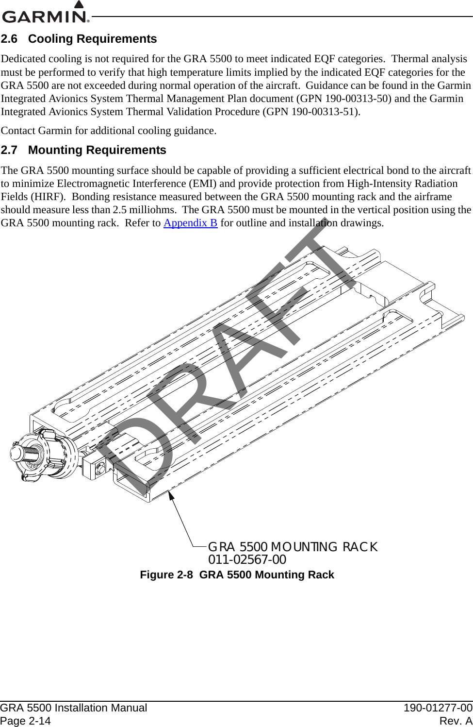
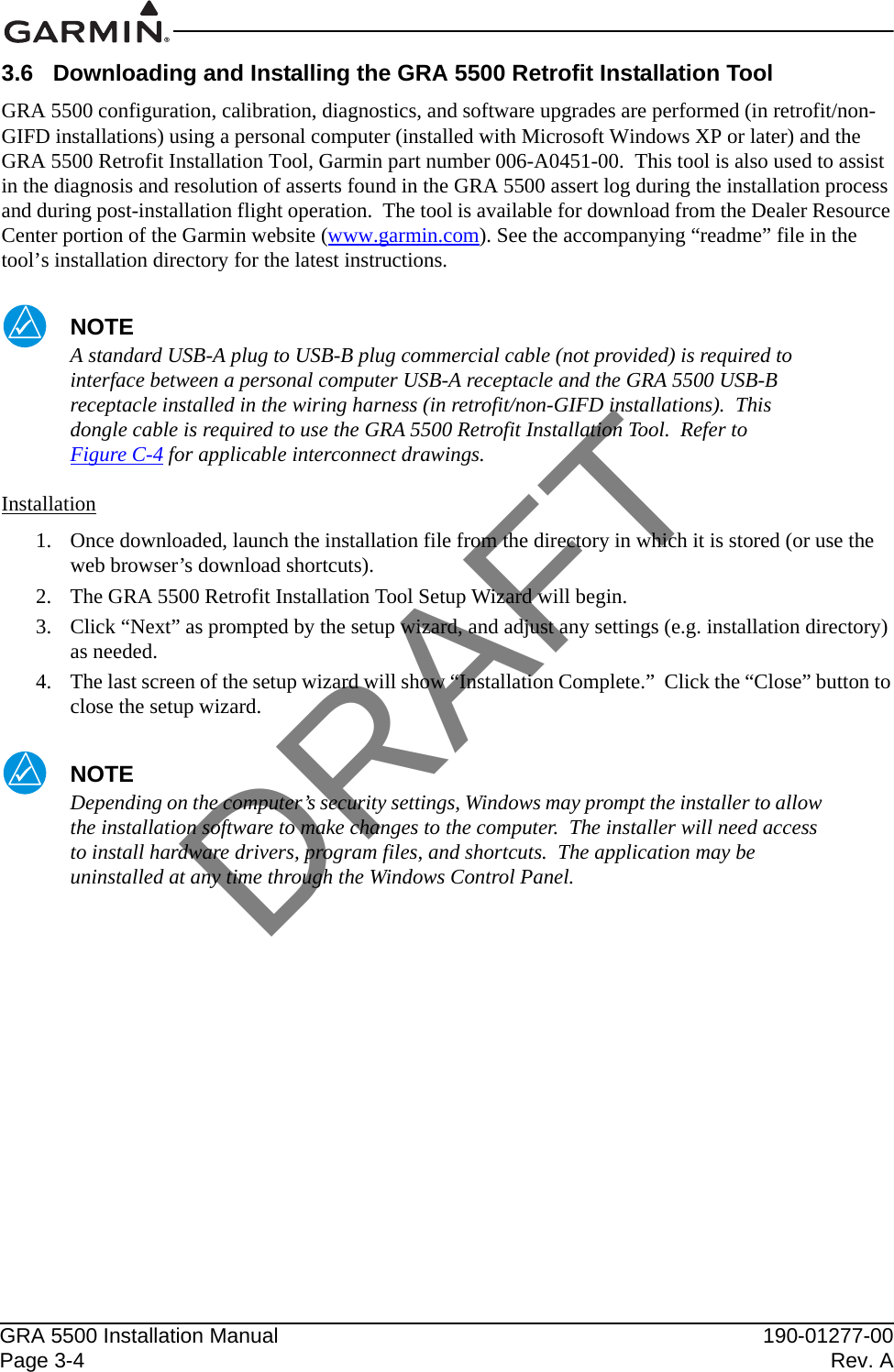
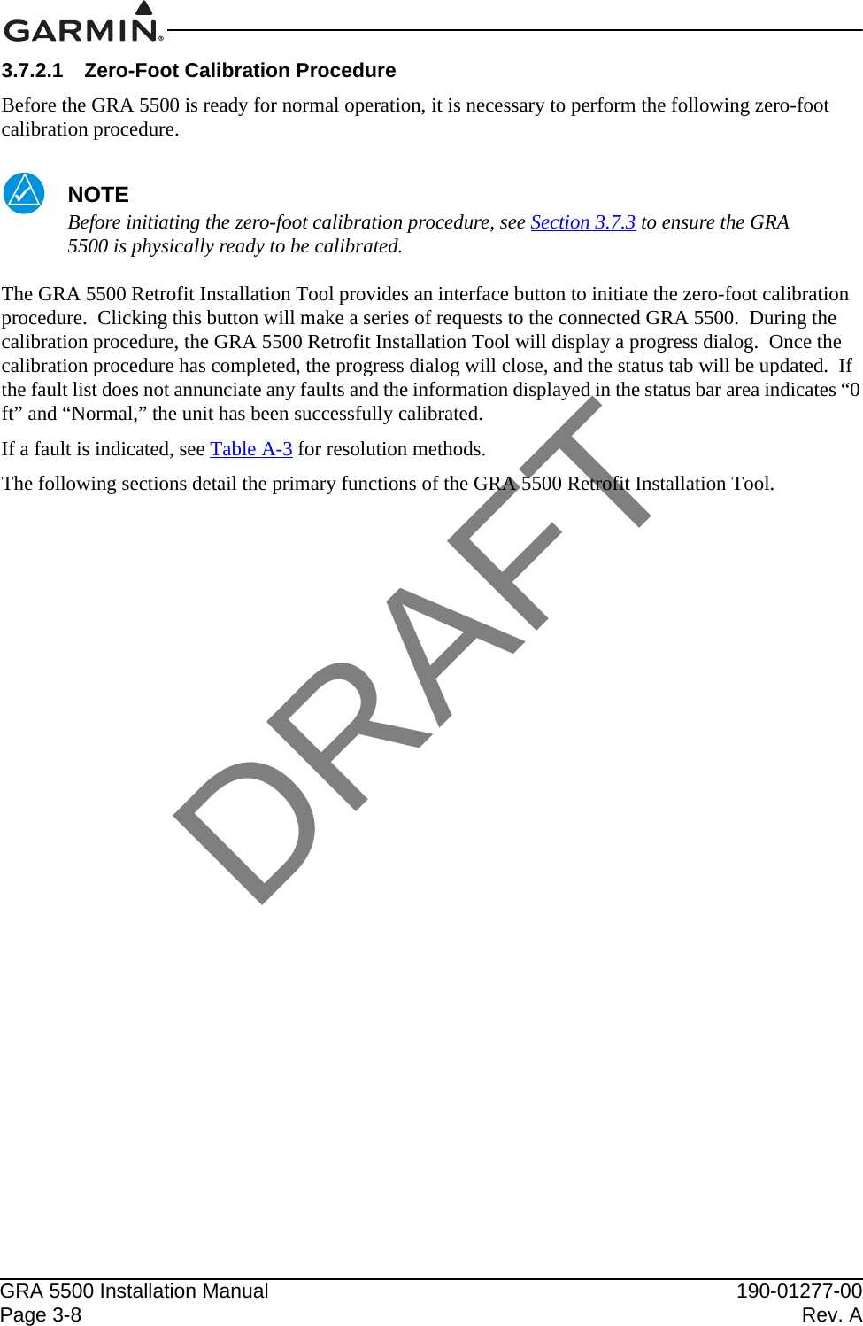
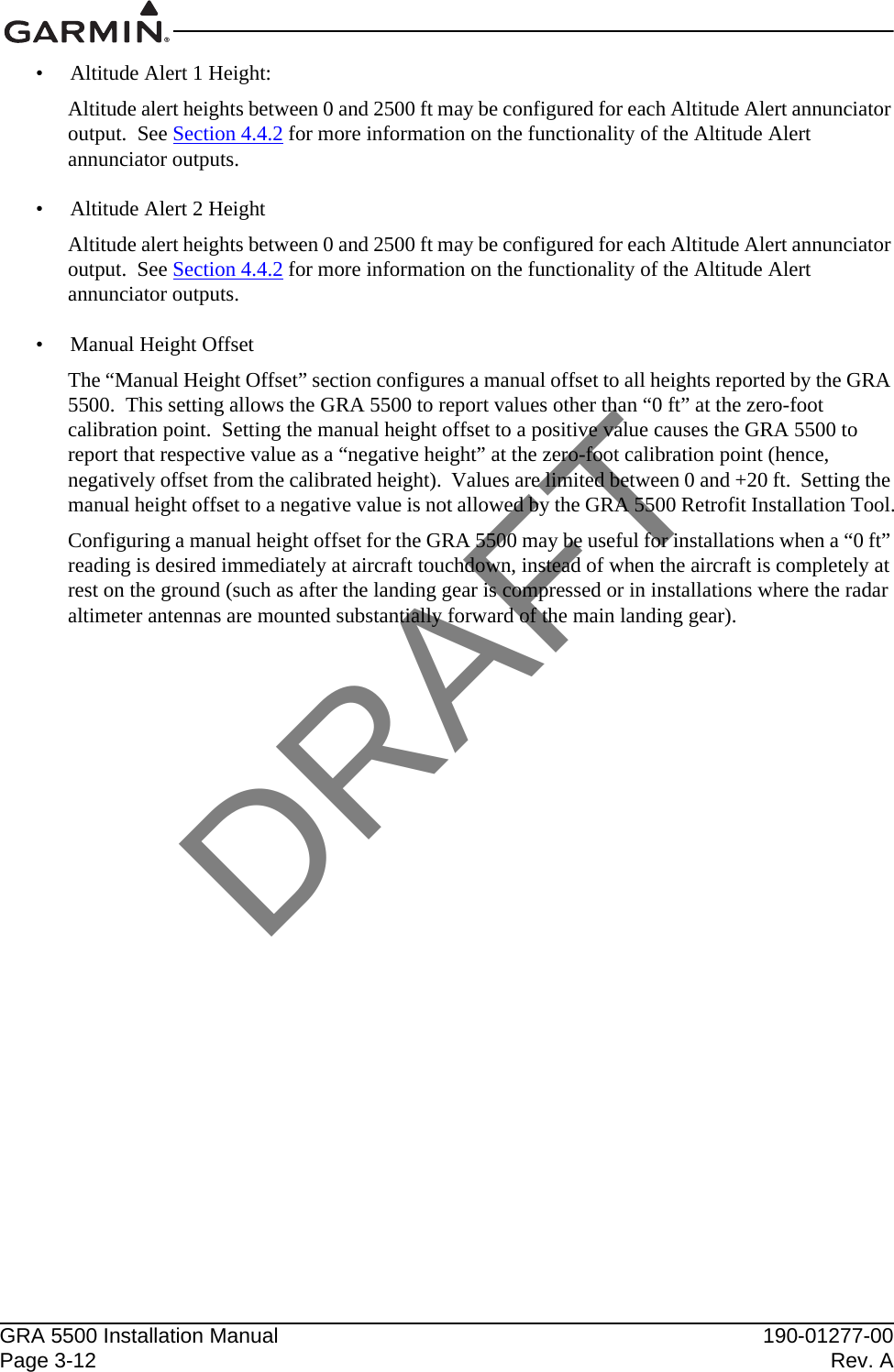
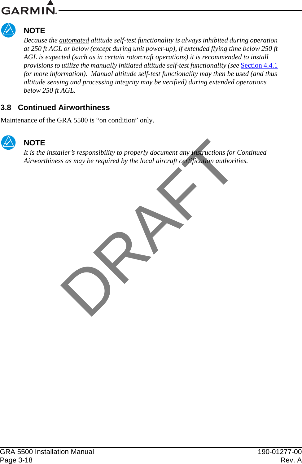
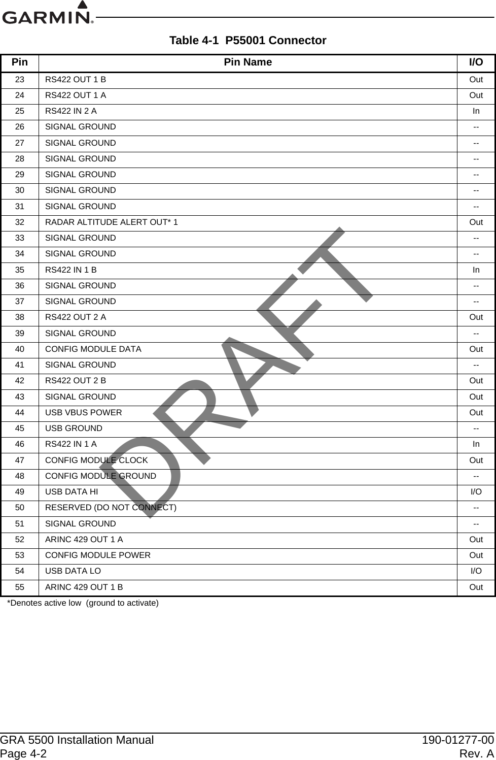
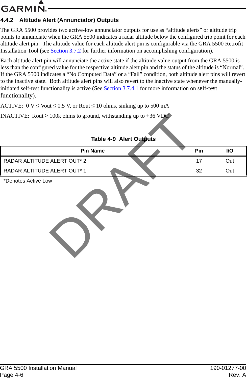
![190-01277-00 GRA 5500 Installation ManualRevision A Page B-1APPENDIX B Outline and Installation DrawingsFigure B-1 GRA 5500 Outline Drawing3.00 76.23.02 76.73.99101.3TNC CONNECTOR2X7.88200.211.62 (NO CONFIGURATION MODULE)295.2.20 5.1.6115.510.40 264.212.08 306.9 (WITH CONFIGURATION MODULE)2.2564.91252X 7.000±.005177.80±0.132X 2.150±.00554.61±0.132X .42510.802X .63016.004X .210±.003 5.33±0.08SEE NOTE 31.538NOTES:DIMENSIONS: INCHES[mm].1.DIMENSIONS ARE SHOWN FOR REFERENCE ONLY.2.MOUNTING HOLES FOR #10 PAN HEAD OR HEX HEAD FASTENERS.3.DRAFT](https://usermanual.wiki/Garmin/0181200/User-Guide-1885115-Page-62.png)