Garmin 0183700 LICENSED NON-BROADCAST AERONAUTICAL TRANSMITTER User Manual 190 00303 24 01
Garmin International Inc LICENSED NON-BROADCAST AERONAUTICAL TRANSMITTER 190 00303 24 01
UserManual.wiki
>
Garmin
>
0183700 User Manual
Users Manual
Navigation menu
Upload a User Manual
Namespaces
Wiki Guide
HTML
PDF
Info
Views
User Manual
Discussion / Help
Navigation

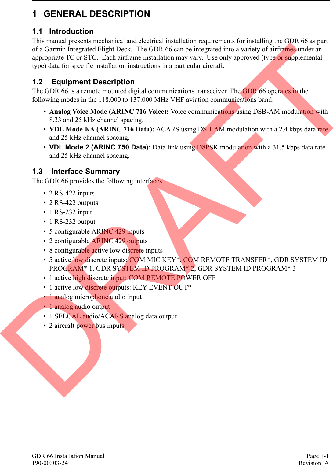
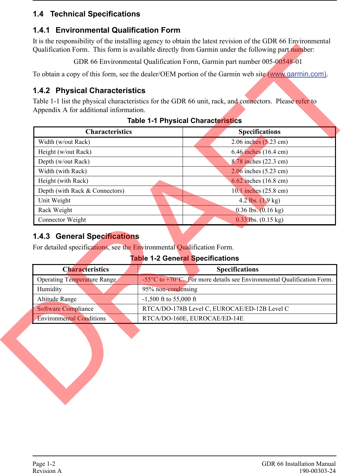
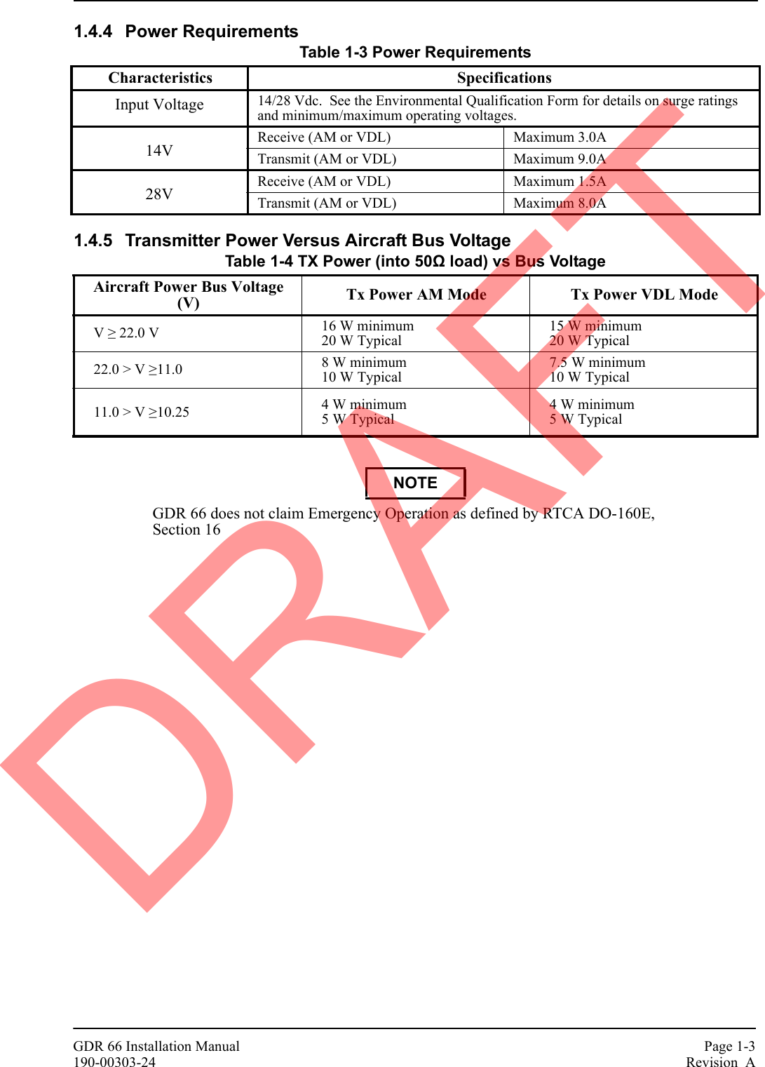
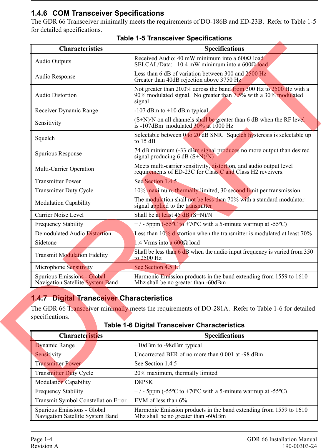
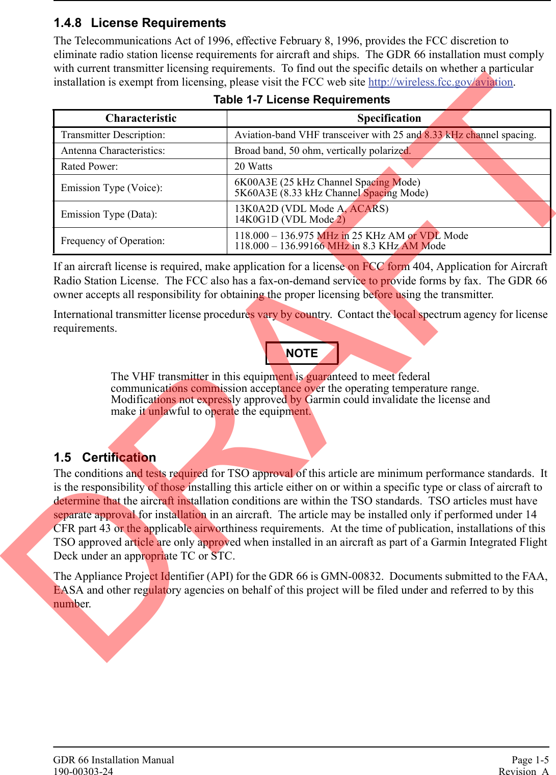


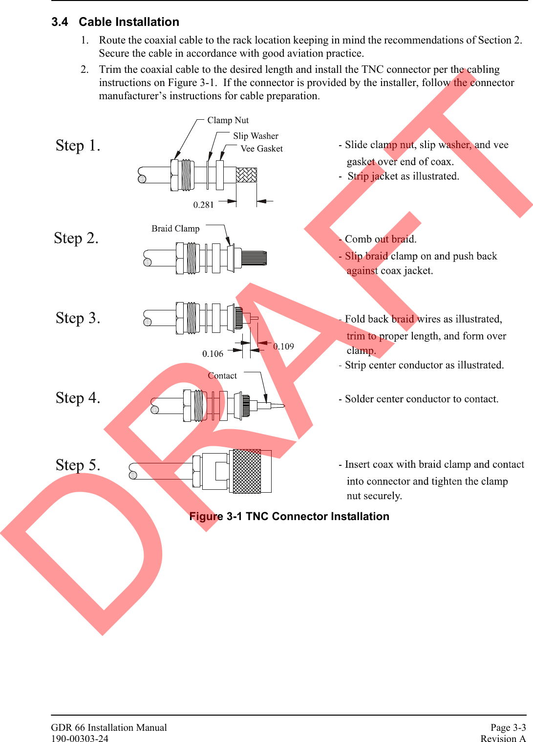

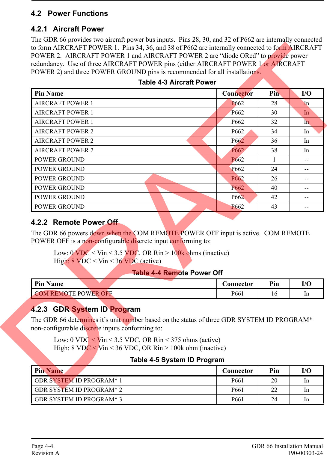
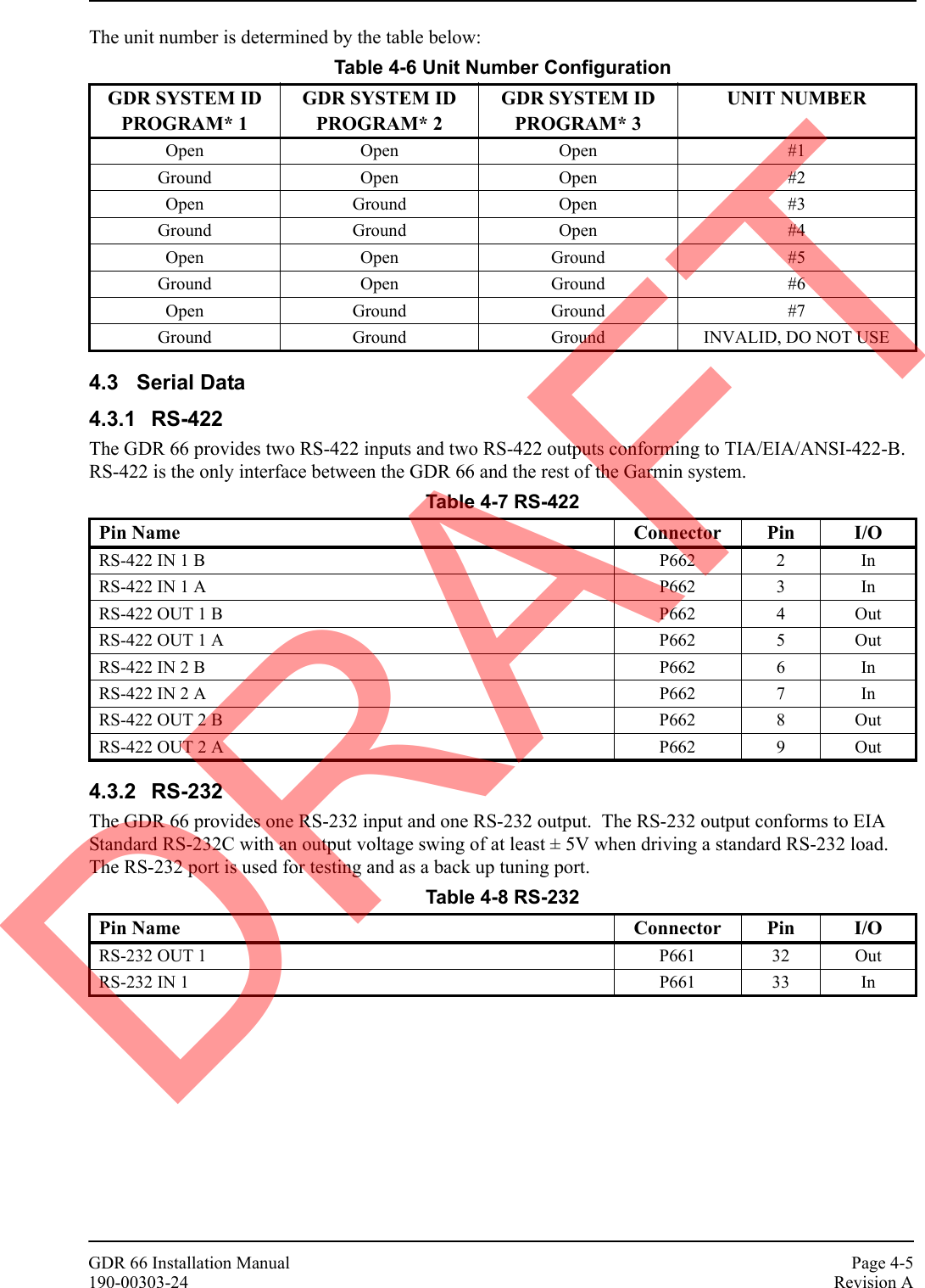
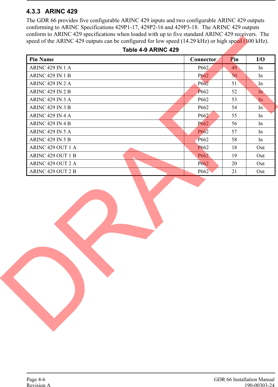
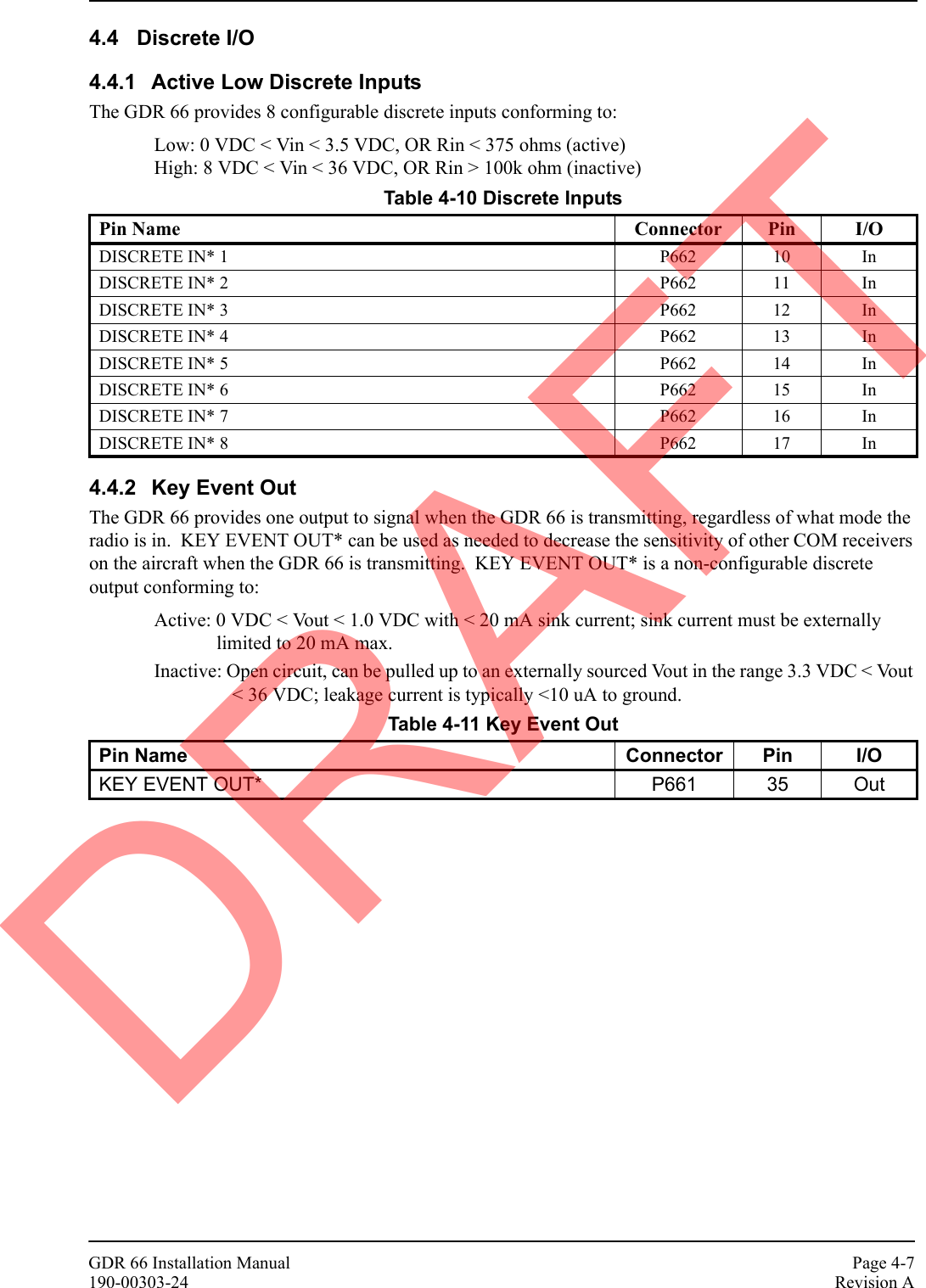

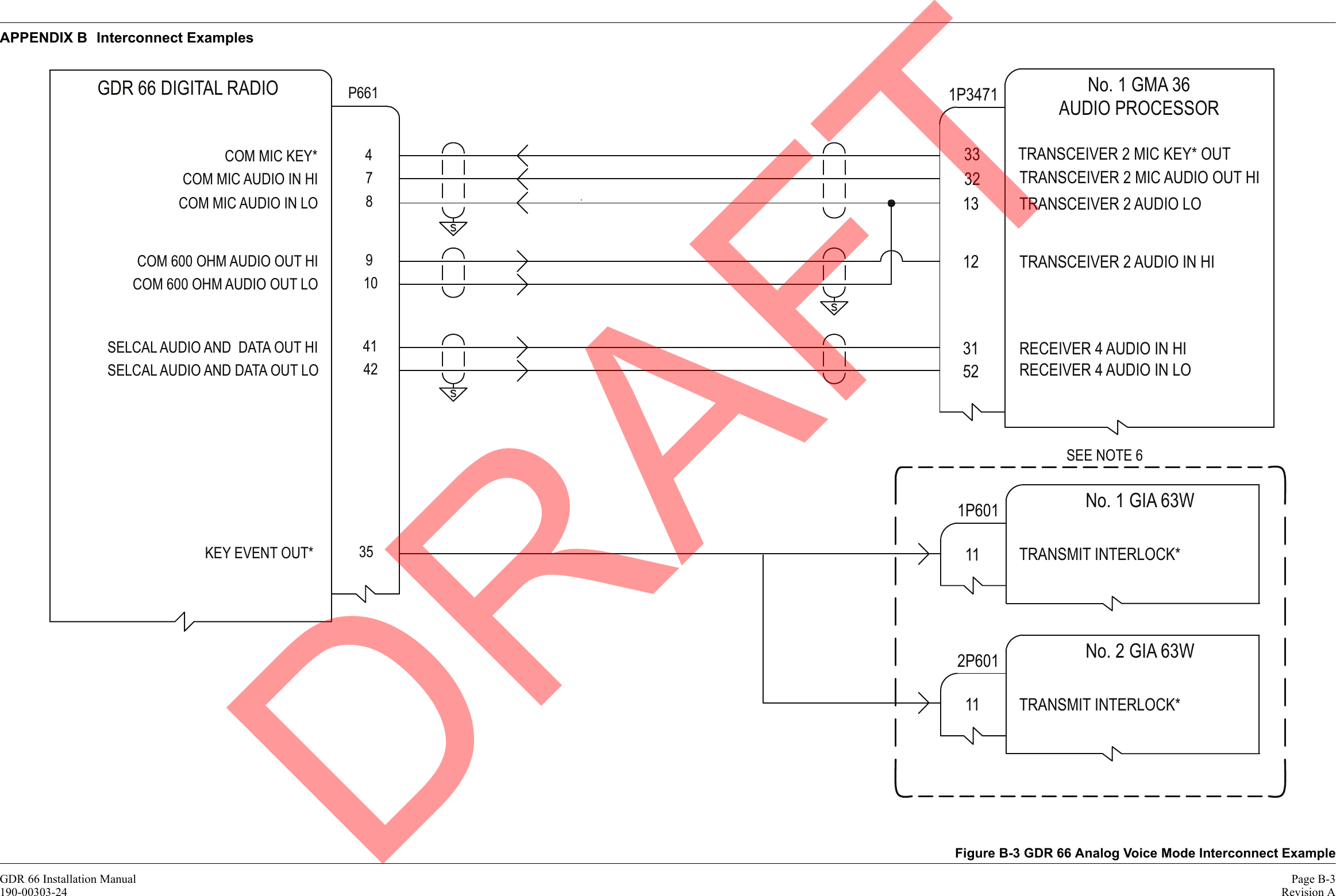
![GDR 66 Installation Manual Page A-1190-00303-24 Revision AAPPENDIX A Outline and Installation DrawingsFigure A-1 GDR 66 Outline Drawing.8 20CG81CG3.21174.6CGP662P661COM(TNC CONNECTOR)NOTES:DIMENSIONS: INCHES[mm]1.DIMENSIONS ARE SHOWN FOR REFERENCE ONLY2.MOUNTING HOLES FOR #10 PAN HEAD OR HEX HEAD FASTENERS (4 PLACES)3.SEE NOTE 3±.005±0.25±0.13±.010 177.82X7.002X5.331.2652.3.21010.22.06±.010.4032.0±0.254X2X2X .85 21.610.14 257.66.62 168.18.17 207.5DRAFT](https://usermanual.wiki/Garmin/0183700/User-Guide-1663874-Page-35.png)