Garmin 01853 LOW POWER TRANSMITTER (2400-2483.5 MHz) User Manual
Garmin International Inc LOW POWER TRANSMITTER (2400-2483.5 MHz) Users Manual
Garmin >
Contents
- 1. Users Manual Vector ISPI
- 2. Users Manual
Users Manual

Quick Start Manual (EN)
Quick Start Manual (FR)
Quick Start Manual (IT)
Quick Start Manual (DE)
Quick Start Manual (ES)
Quick Start Manual (PT)
Draft_190-01450-90_QSM.indd 1 2/1/2012 1:36:39 PM

2
Getting Started
WARNING
Read all instructions carefully before
installing and using Vector. Improper use
could result in serious injury.
See the Important Safety and Product
Information guide in the product box for
product warnings and other important
information.
NOTICE
Go to www.garmin.com/vector for the
latest bike compatibility information.
Tools Needed
• 15 mm pedal wrench
• Bike grease
• 4 mm hex key (allen wrench)
Installing the Vector
Components
Preparing the Crank Arms
1 Remove the existing pedals.
2 Clean the threads and remove old
grease.
3 Apply a thin layer of grease on the
threads.
Draft_190-01450-90_QSM.indd 2 2/1/2012 1:36:39 PM
3
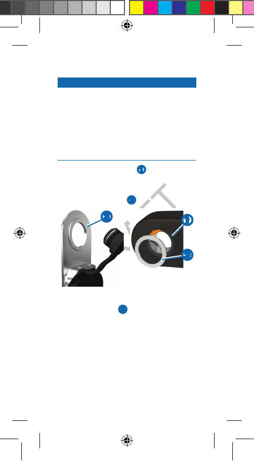
Determining Pedal Pod Clearance
NOTICE
The pedal pod should only contact the
crank arm at its mounting face (see
below), because this is a load-bearing
connection. If the pedal pod contacts the
crank arm anywhere else, the pedal pod
may fracture or break when the pedal is
tightened.
• If the mounting face ➊ surrounding
the threaded hole in the crank arm is
recessed more than ½ mm, use one
or more washers ➋ to ll the recess.
➋
➊
➌
• Make sure that the pedal pod
mounting face ➌ contacts the crank
arm at its mounting face. If it touches
anywhere else, use another washer to
provide the necessary clearance.
• If the mounting face of the crank arm
is protruding, do not use washers.
Draft_190-01450-90_QSM.indd 3 2/1/2012 1:36:52 PM
4
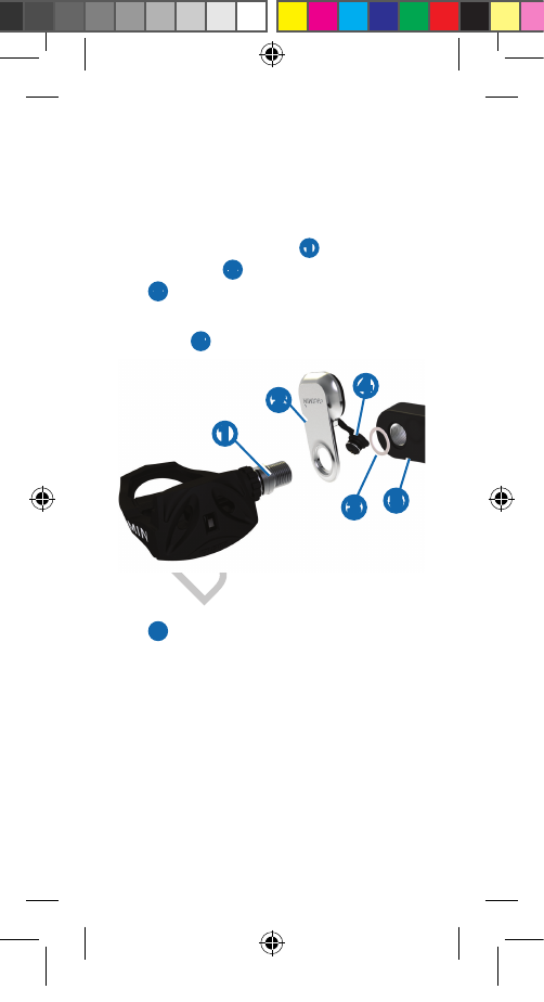
Installing the Pedal Pod and Pedal
NOTE: Left and right pedal pods are the
same.
1 Install the left pedal rst.
2 On the pedal spindle ➊, stack the
pedal pod ➋, and optional washers
➌.
TIP: You must carefully bend the
cable ➍ out of the way.
➊
➋➍
➌➎
3 Insert the spindle into the crank arm
➎.
4 Hand tighten the spindle.
NOTE: The left pedal tightens counter
clockwise. The right pedal tightens
clockwise.
TIP: It does not matter which way the
pedal pod hangs from the pedal. You
should rotate the crank arm a few
times to check for clearance.
Draft_190-01450-90_QSM.indd 4 2/1/2012 1:36:56 PM
5
Installing the Pedal Pod and Pedal
NOTE: Left and right pedal pods are the
same.
1 Install the left pedal rst.
2 On the pedal spindle ➊, stack the
pedal pod ➋, and optional washers
➌.
TIP: You must carefully bend the
cable ➍ out of the way.
3 Insert the spindle into the crank arm
➎.
4 Hand tighten the spindle.
NOTE: The left pedal tightens counter
clockwise. The right pedal tightens
clockwise.
TIP: It does not matter which way the
pedal pod hangs from the pedal. You
should rotate the crank arm a few
times to check for clearance.
5 Use the pedal wrench to tighten the
nut on the spindle.
NOTE: Garmin recommends torque of
25 to 30 lbf-ft. (34 to 40 N-m).
6 Firmly plug the cable into the spindle.
7 Rotate the crank arm to check for
clearance.
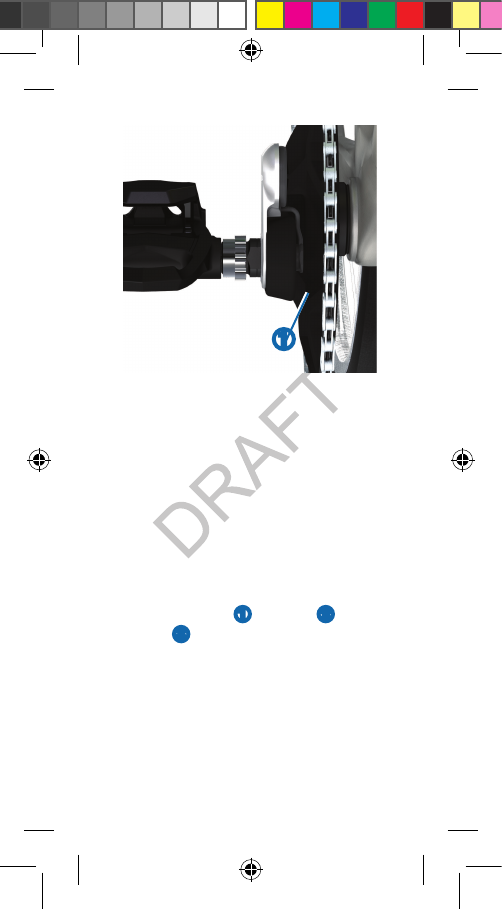
Determining the Bicycle Chain
Clearance
Before you can install the right pedal, you
must determine bicycle chain clearance.
1 Move your bike chain to the largest
crank gear and the smallest cassette
gear.
The bike chain should be in the
outermost position to determine
proper clearance between the pedal
pod cable and the chain.
NOTE: There must be at least 3 mm
clearance ➊ between the chain and
the crank arm.
Draft_190-01450-90_QSM.indd 5 2/1/2012 1:37:00 PM
6
➊
2 Repeat steps 2–7 from “Installing the
Pedal Pod and Pedal.”
NOTE: If the pedal pod cable rubs the
chain, you can add washers between
the pedal pod and the crank arm to
increase clearance.
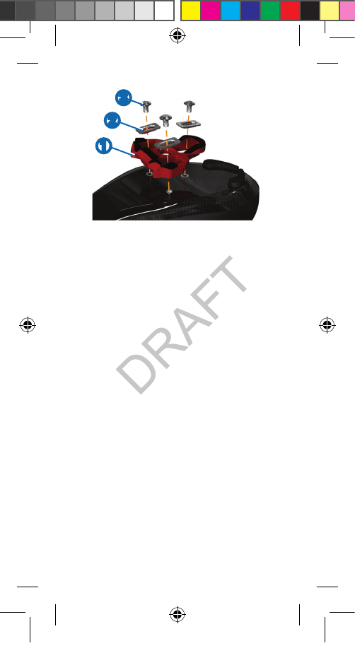
Installing the Shoe Cleats
NOTE: Left and right cleats are the same.
1 Lightly grease the cleat bolt threads.
2 Align the cleat ➊, washers ➋, and
bolts ➌.
Draft_190-01450-90_QSM.indd 6 2/1/2012 1:37:07 PM
7
➊
➋
➌
3 Use the hex key to loosely attach
each bolt to the sole of the shoe.
4 Adjust the cleat to the shoe in your
preferred position.
This can be adjusted after a trial ride.
5 Tighten the cleat rmly to the shoe.
NOTE: Garmin recommends torque of
4 to 6 lbf-ft. (5 to 8 N-m).
Pairing
Before you can view power data on the
Edge, you must pair the devices.
This procedure contains instructions
for the Edge 800. If you have another
compatible device, see your owner’s
manual.
1 Turn on the Edge.
2 Bring the Edge within range (9.8 ft. or
3 m) of the Vector.
Draft_190-01450-90_QSM.indd 7 2/1/2012 1:37:11 PM

8
3 Select MENU > > Bike Settings >
Bike Proles.
4 Select a bike.
5 Select ANT+ Power > Power Meter
> Yes.
6 Press .
When the Vector is paired, a message
appears, and appears solid on
the status page.
Troubleshooting
Getting the Owner’s Manual
You can get the latest owner’s manual
from the web.
1 Go to www.garmin.com/vector.
2 Click Manuals.
Vector Storage
If you are transporting your bicycle or
not using the Vector for a period of time,
Garmin recommends removing the Vector
components and storing them in the
product box.
Draft_190-01450-90_QSM.indd 8 2/1/2012 1:37:11 PM

10
© 2012 Garmin Ltd. or its subsidiaries
Garmin International, Inc.
1200 East 151st Street,
Olathe, Kansas 66062, USA
Garmin (Europe) Ltd.
Liberty House, Hounsdown Business Park,
Southampton, Hampshire, SO40 9LR UK
Garmin Corporation
No. 68, Zhangshu 2nd Road, Xizhi Dist.
New Taipei City, 221, Taiwan (R.O.C.)
www.garmin.com/support
190-01371-90_0A
March 2012
Printed in Taiwan
Garmin® and the Garmin logo are trademarks of
Garmin Ltd. or its subsidiaries, registered in the USA
and other countries. Vector™ is a trademark of Garmin
Ltd. or its subsidiaries. These trademarks may not be
used without the express permission of Garmin.
Draft_190-01450-90_QSM.indd 10 2/1/2012 1:37:14 PM