Garmin 02136 Low Power Transmitter (2400-2483.5 MHz) User Manual 190 00303 91 0A
Garmin International Inc Low Power Transmitter (2400-2483.5 MHz) 190 00303 91 0A
UserManual.wiki
>
Garmin
>
02136 User Manual
>
USERS MANUAL 1
Contents
1.
USERS MANUAL 1
2.
USERS MANUAL 2
USERS MANUAL 1
Navigation menu
Upload a User Manual
Namespaces
Wiki Guide
HTML
PDF
Info
Views
User Manual
Discussion / Help
Navigation

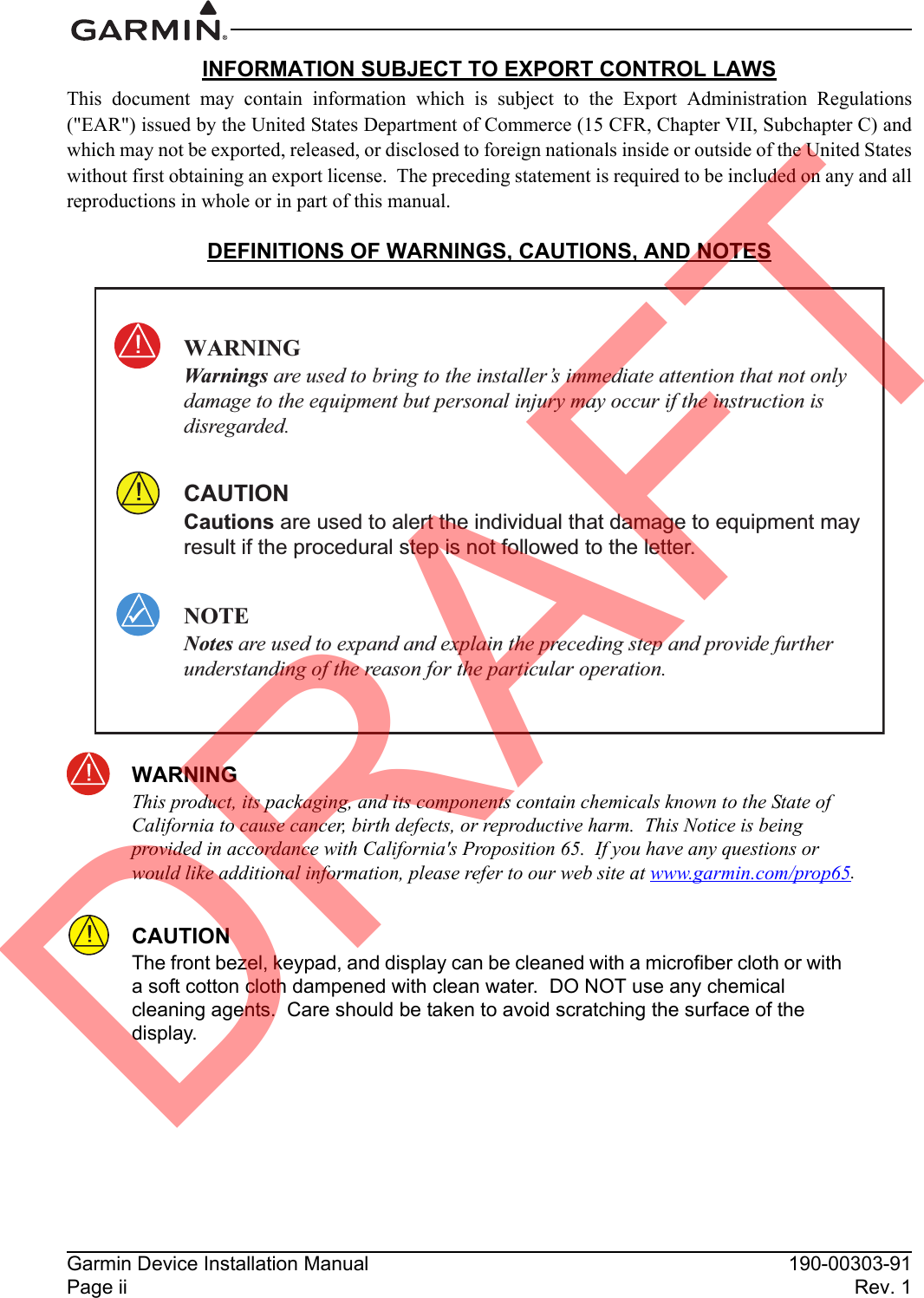
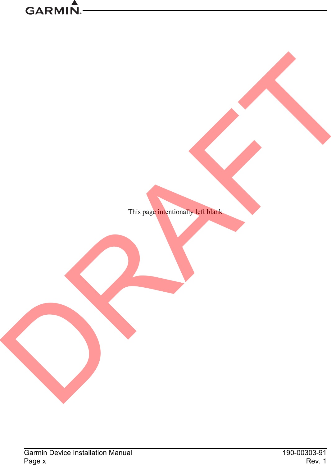
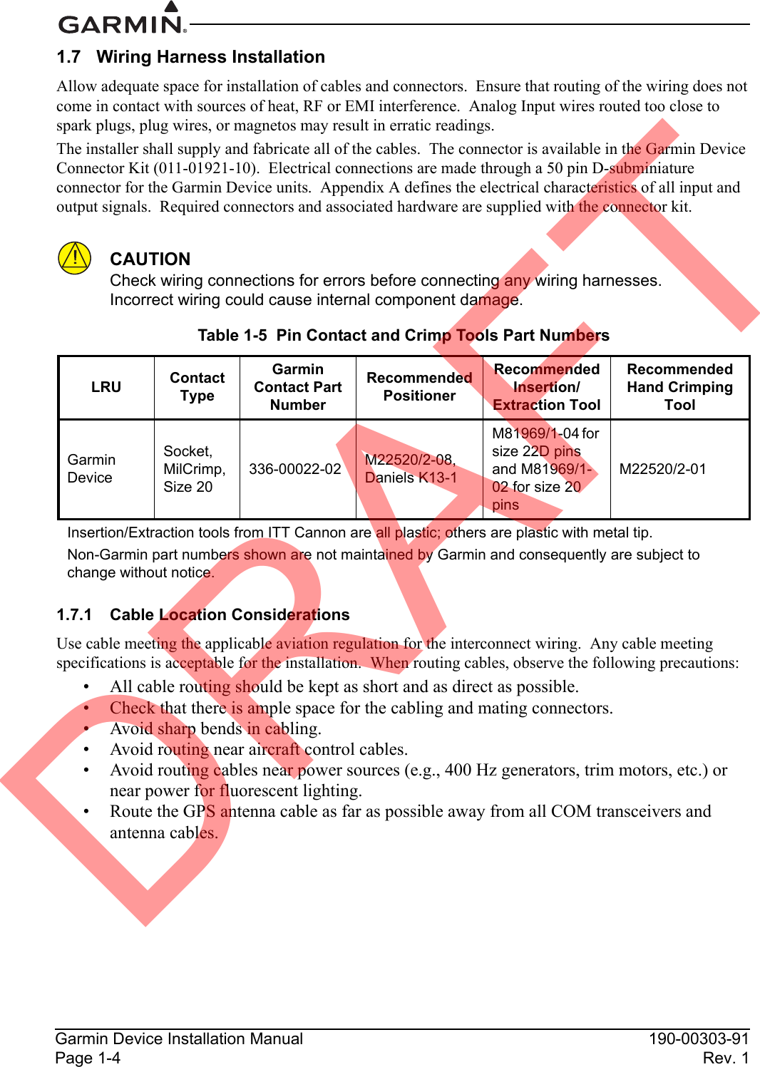
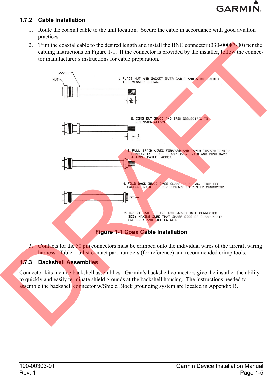

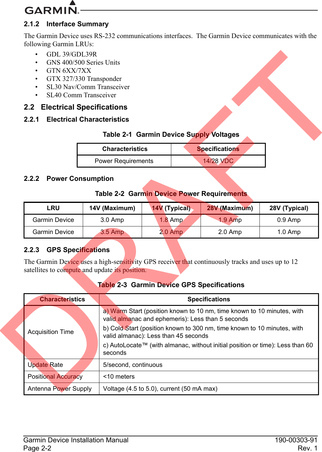
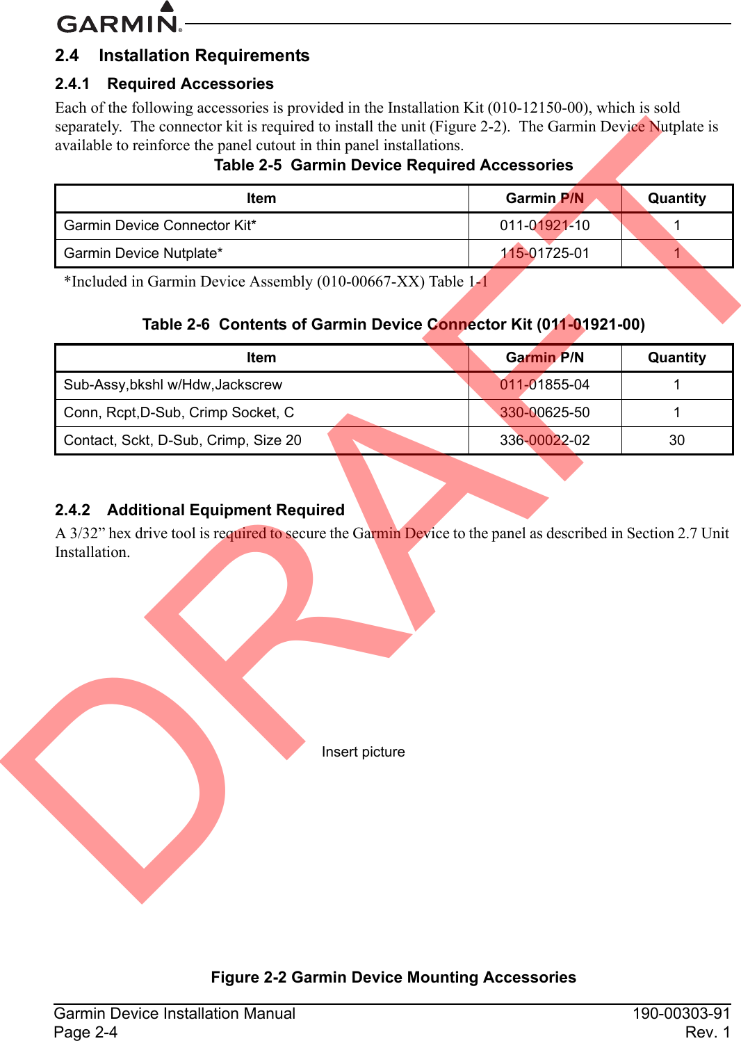
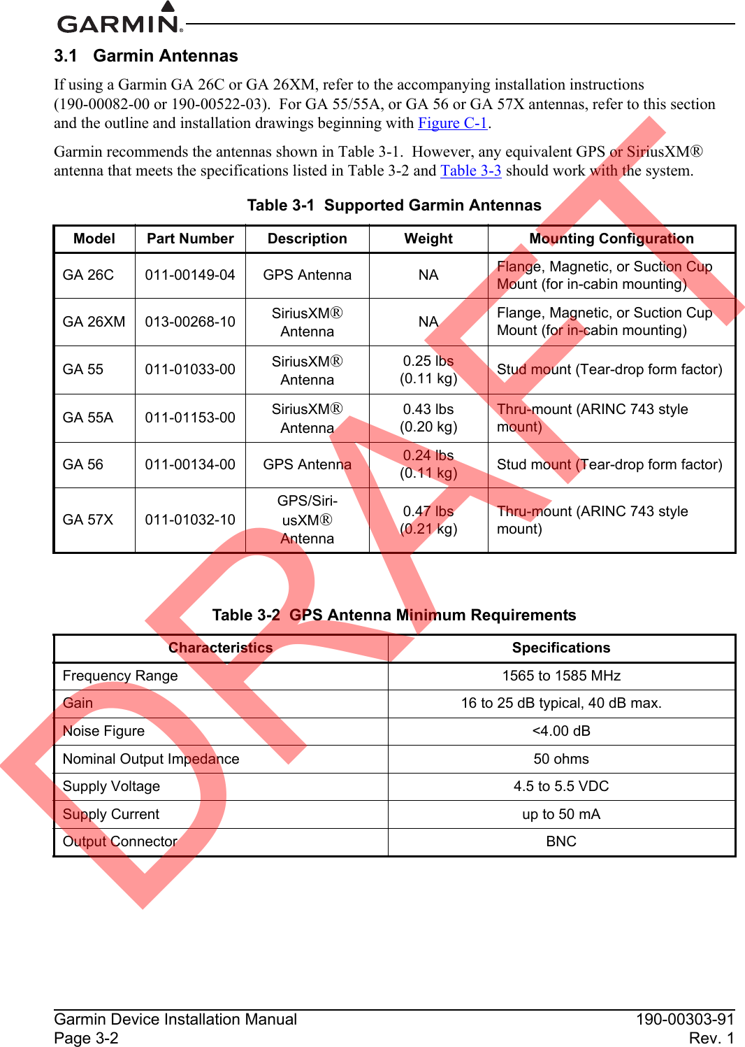
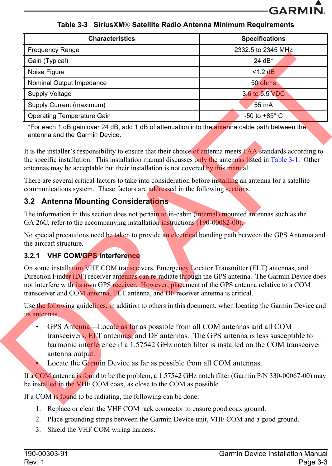
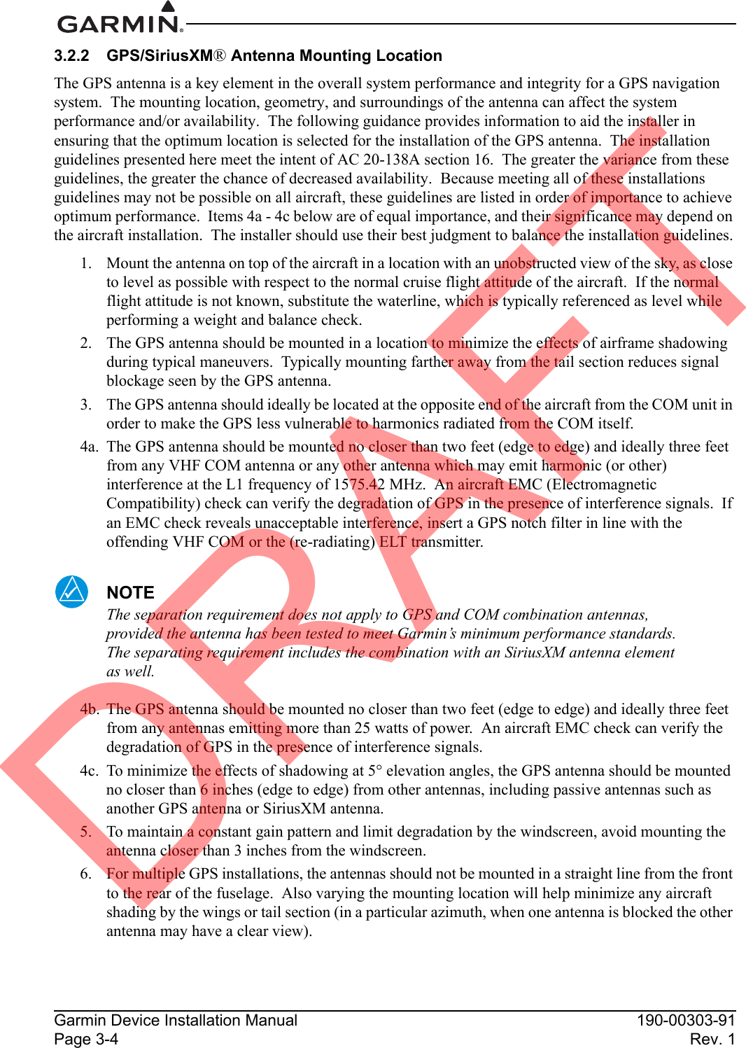
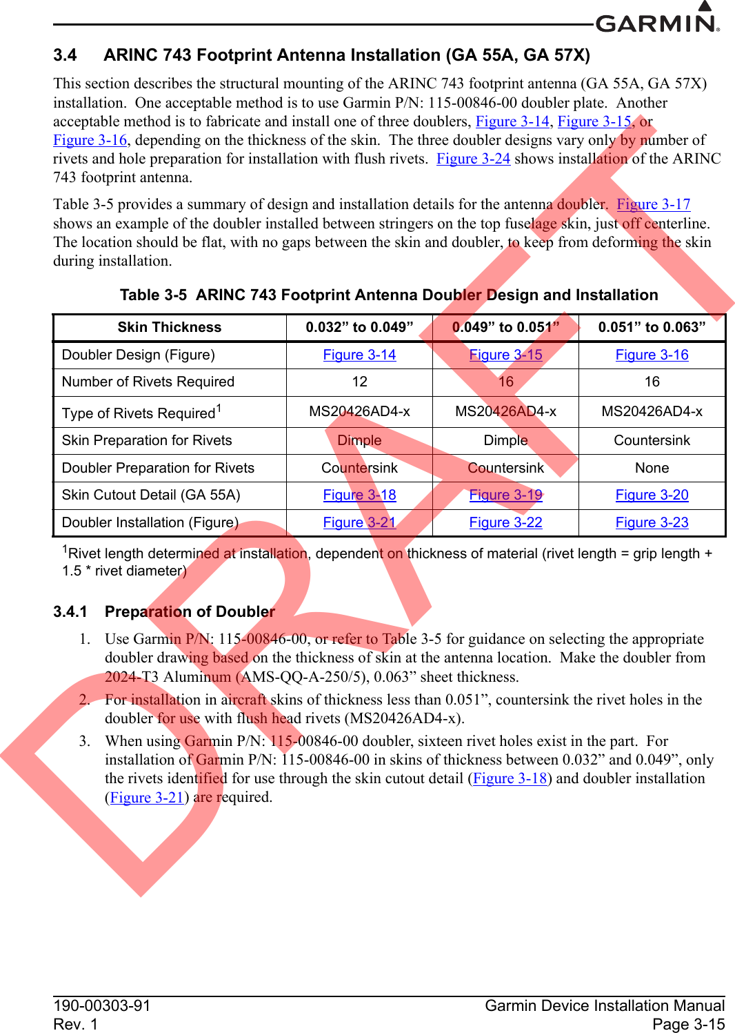
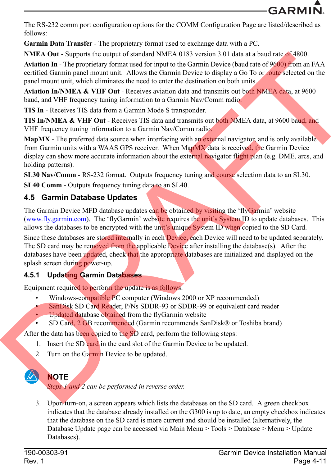
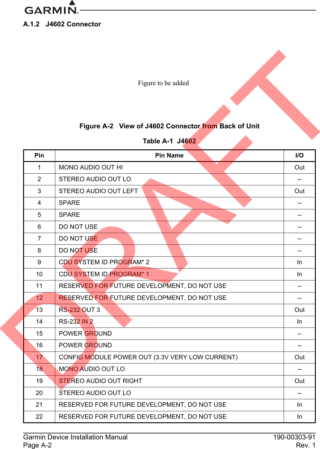
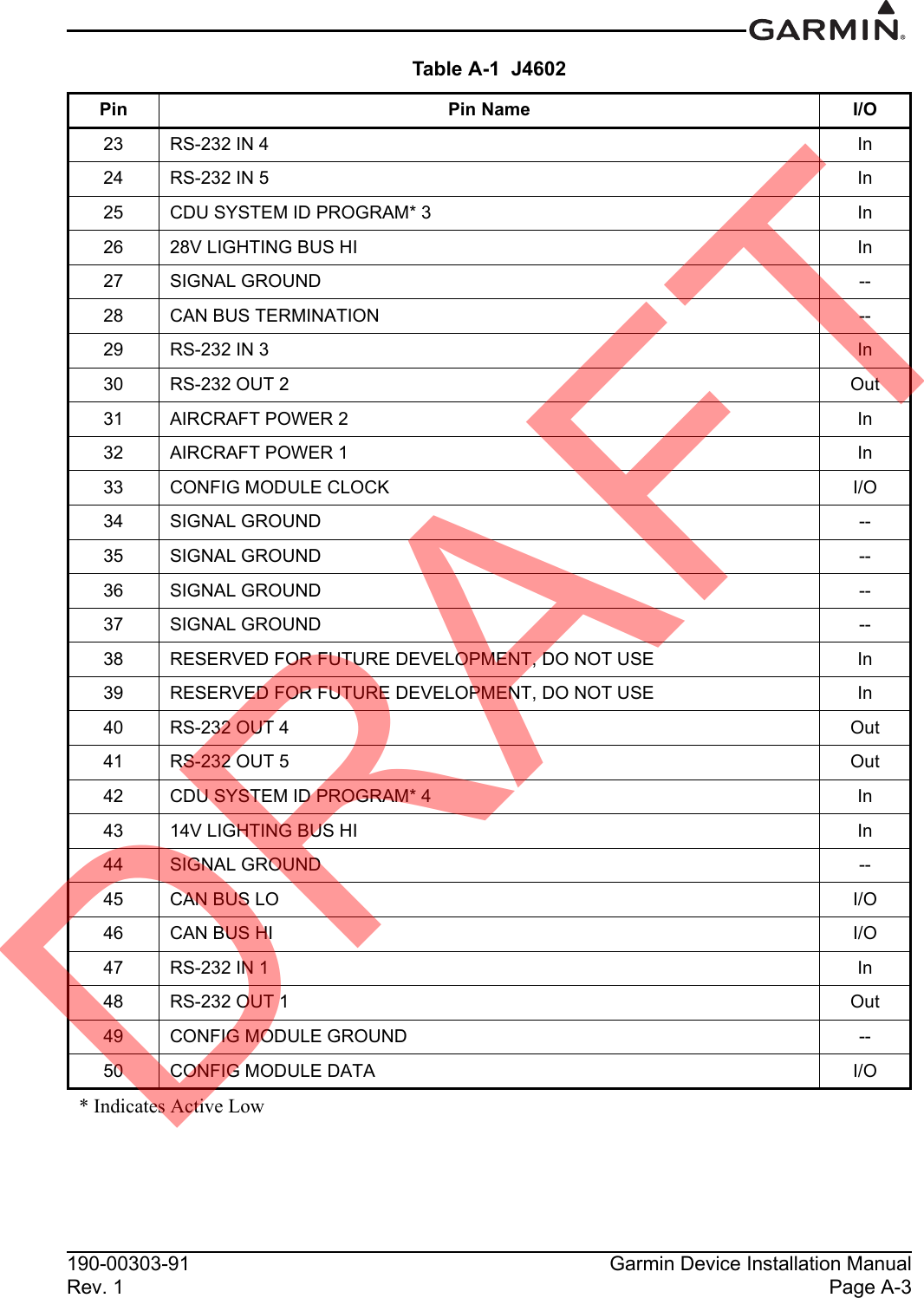
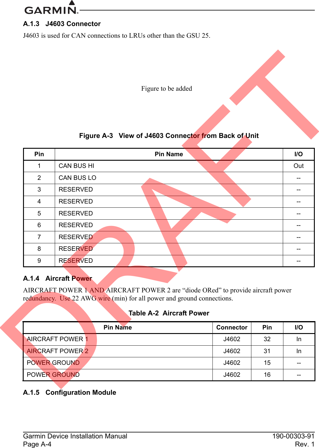
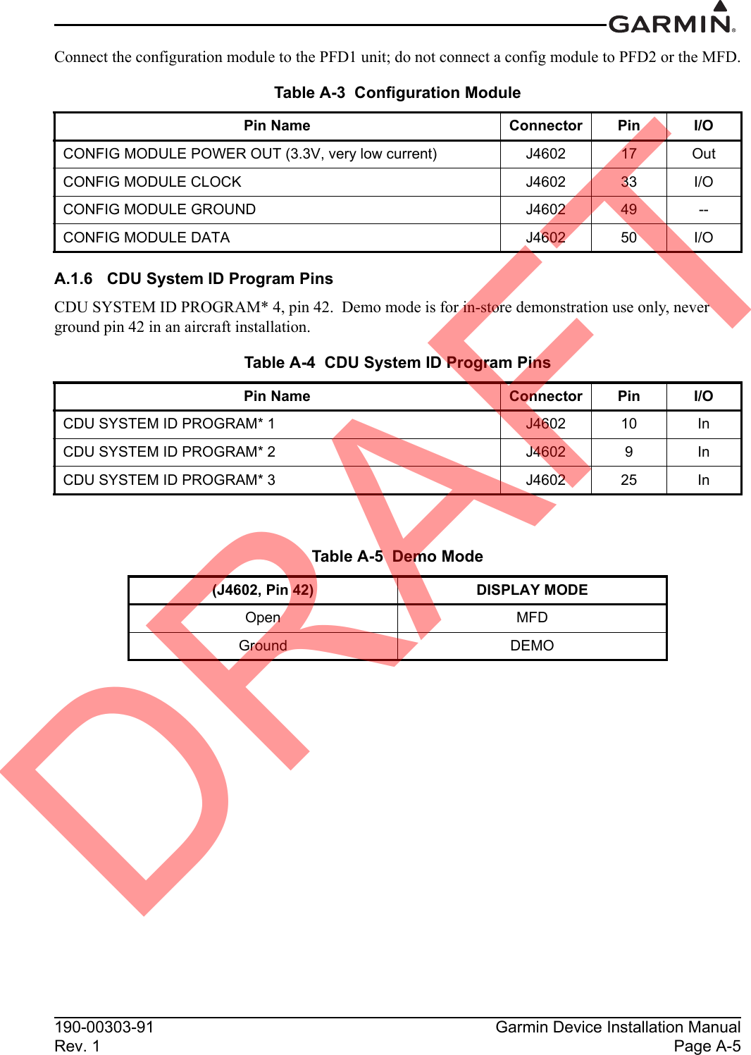
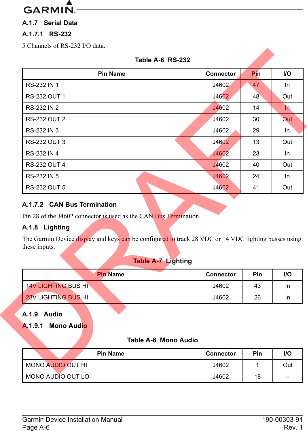
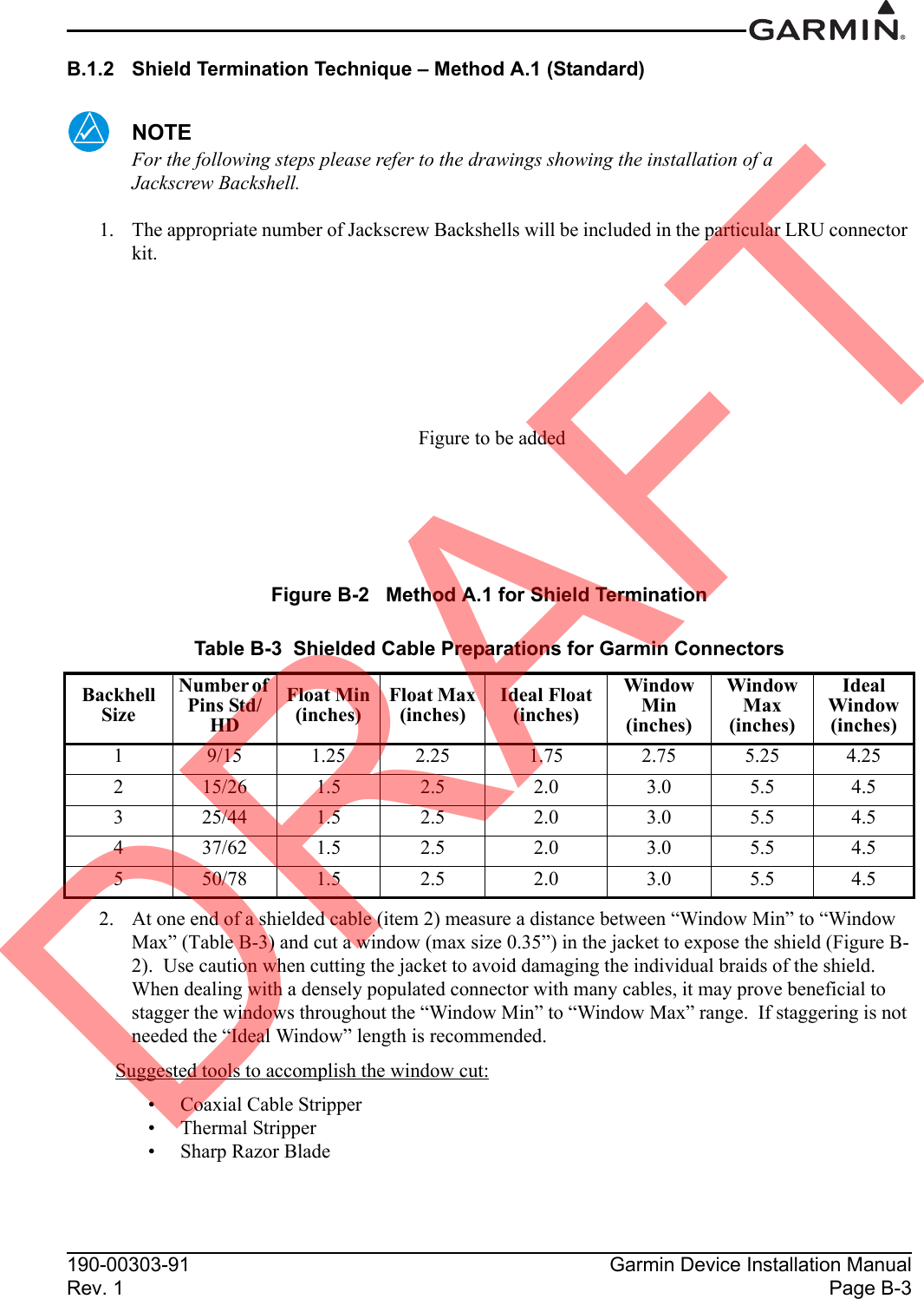
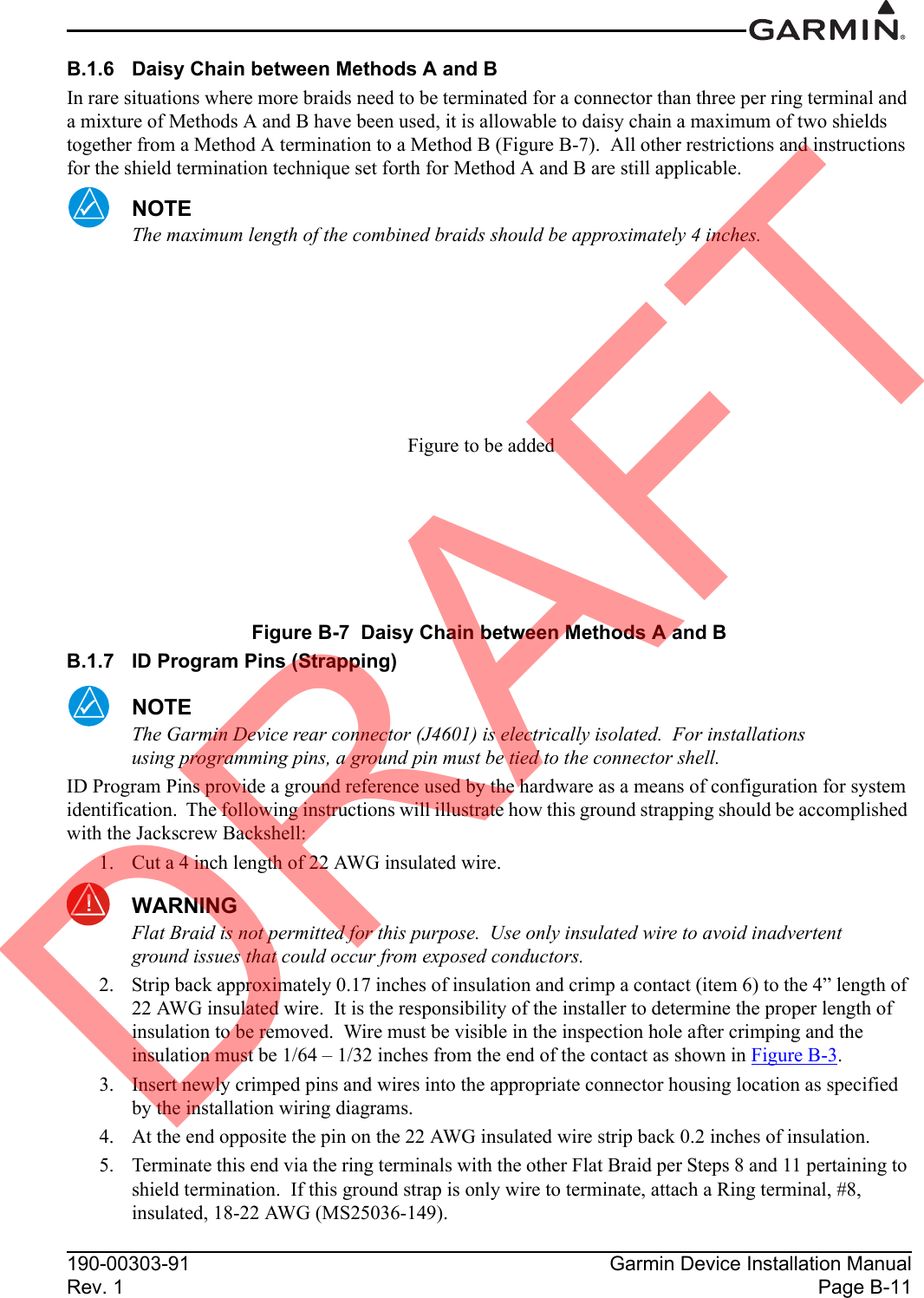
![190-00303-91 Garmin Device Installation ManualRev. 1 Page 2-32.2.4 AntennasTable 2-4 lists Garmin and non-Garmin antennas currently supported by the Garmin Device. Refer to Section 3 for Garmin antenna installation information. For non-Garmin antennas, follow the manufacturer’s installation instructions.NOTEThe GPS antenna should provide a gain of 16 to 25dB, and requires a 4.5V to 5V supply voltage that can provide 50mA max.2.3 Environmental Specifications The Garmin Device has an Operating Temperature Range of -20°C to +60°C. Table 2-4 Garmin Device Supported AntennasModel Mount Style Conn Type Antenna Type Mfr Antenna Part NumberGarmin Order NumberGA 26CSuction Cup, Magnetic or Flange MtBNC GPS Garmin 011-00149-04 010-10052-04GA 26XM Ground Plane Mt TNC SiriusXM®Garmin 013-00268-10 010-11373-00GA 55 Stud Mount TNC SiriusXM®Garmin 011-01033-00 010-10600-01GA 55A ARINC 743 TNC SiriusXM®Garmin 011-01153-00 010-10598-00GA 56 Stud Mount BNC GPS Garmin 011-00134-00 010-10040-01GA 57X [1]Screw Mount, ARINC 743 FootprintBNC TNCGPS SiriusXM®Garmin 011-01032-10 010-11370-10[1] The GPS antenna connector is BNC type. The SiriusXM® antenna connector is TNC type.DRAFT](https://usermanual.wiki/Garmin/02136.USERS-MANUAL-1/User-Guide-2213591-Page-21.png)