Garmin 02552 Marine Radar Transmitter User Manual 1
Garmin International Inc Marine Radar Transmitter 1
UserManual.wiki
>
Garmin
>
02552 User Manual
>
User Manual 1
Contents
1.
User Manual 1
2.
User Manual 2
3.
User Manual
4.
User Manual Install Guide
User Manual 1
Navigation menu
Upload a User Manual
Namespaces
Wiki Guide
HTML
PDF
Info
Views
User Manual
Discussion / Help
Navigation
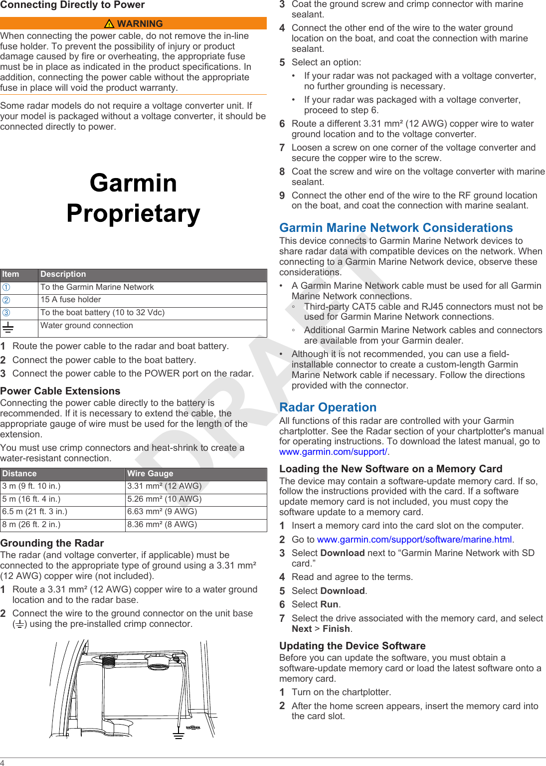
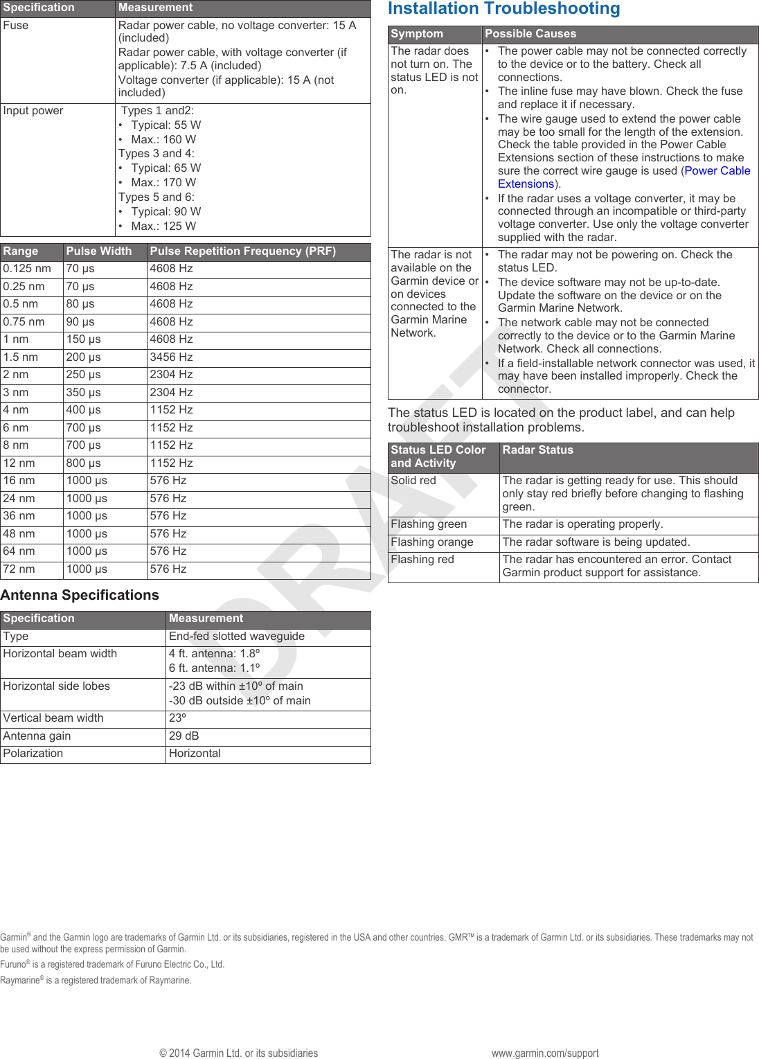
![DRAFT• Secure the included mounting template to the surface at the chosen mounting location, along the bow-stern axis as indicated on the template.2Determine which of the two mounting-hole patterns indicated on the template are appropriate for the mounting surface and drill the four mounting holes using a 15 mm (19/32 in.) drill bit.3Remove the hatch on the front of the unit by loosening the screw and lifting it off of the hinges.4Apply the included Petrolatum Primer to one half of the threads of the four threaded rods.5Insert the ends of the threaded rods coated in Petrolatum Primer into the unit base, matching the hole pattern chosen in step 2.6Tighten the threaded rods À using a 5 mm hex wrench Á.To avoid damaging the unit base, you should stop tightening the threaded rods when they no longer turn easily.7Install the isolators  over the threaded rods, and push them securely onto the four raised locations on the bottom of the base. Ã.Mounting the RadarBefore you can mount the radar, you must first select a mounting location, and prepare the mounting surface and the radar (Preparing the Surface and the Radar for Mounting).1Take note of which end of the unit you plan to mount facing the bow along the bow-stern axis.If the hatch side is facing the bow, you must adjust the front-of-boat offset on the chartplotter to receive an accurate radar reading (Front-of-Boat Offset).2Position the included strap over the unit top, as close to the unitbase as possible À.3Hoist the radar into position, and carefully lower it onto the mounting surface, feeding the threaded rods through the holes.4From under the mounting surface, place the shoulder washers Á on the threaded rods and feed them into the mounting surface so they fit securely.5Place the flat washers Â, lock washers Ã, and hex nuts Ä on the threaded rods.6Torque the hex nuts to 1.5 kgf-m (130 lbf-in. [11 lbf-ft.]) to securely fasten the radar to the surface without damaging the radar or the mounting hardware.Installing the unit topBefore you can install the unit top on the radar, you must securely mount the base ( Mounting the Radar).1Remove the protective cover from the waveguide on the top of the base.2Align the waveguide À on the base with the socket on the bottom of the unit top Á, and slide the unit top onto the base.2](https://usermanual.wiki/Garmin/02552.User-Manual-1/User-Guide-2428226-Page-2.png)
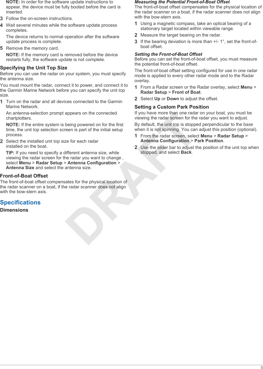
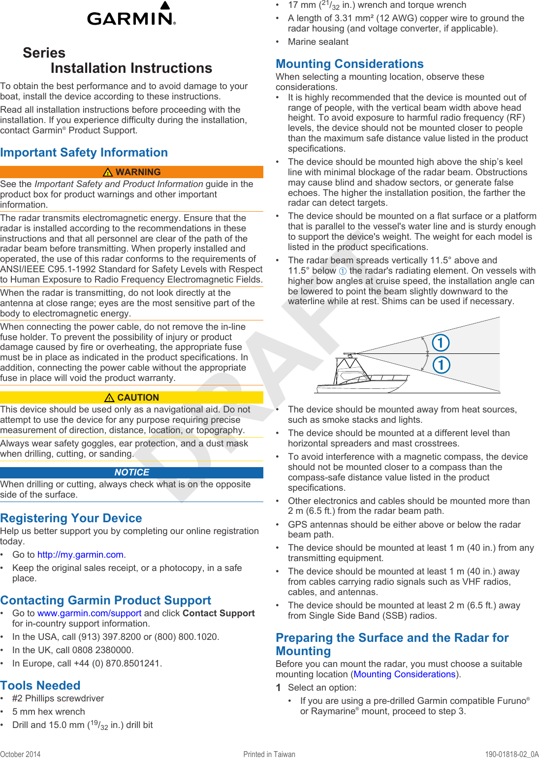
![DRAFT3Secure the antenna to the unit base using the included hex bolts  and spring washers Ã.4Torque the hex bolts to 0.81 kgf-m (70 lfb-in. [6 lbf-ft.]) to fasten the antenna to the unit base without damaging the antenna or the mounting hardware.Cable ConsiderationsIt may be necessary to drill 31.7 mm (1 ¼ in.) holes for routing the power or network cable. The provided rubber cable grommet can be used to cover a cable installation hole.• The grommet does NOT provide a waterproof seal. To make the grommet waterproof, marine sealant must be applied.• If needed, the grommet can be trimmed to route both the power and the network cable through the same hole.• Additional cable grommets can be purchased from Garmin or a Garmin dealer.When installing the power and network cables, you should observe these considerations.• Cutting the Garmin Marine Network cable is not recommended, but a field install kit can be purchased from Garmin or a Garmin dealer if cutting the network cable is necessary.• To ensure safety, appropriate tie-wraps, fasteners, and sealant should be used to secure the cable along the route and through any bulkheads or the deck.• Cables should not be run near moving objects and high-heat sources or through doorways and bilges.• To avoid interference with other equipment, power and network cables should not be run next to or parallel to other cables, such as radio antenna lines or power cables. If this is not possible, the cables should be shielded with metal conduit or a form of EMI shielding.• The power cable should be installed as close to the battery source as possible.◦ If it is necessary to extend the power cable, the appropriate gauge of wire must be used (Power Cable Extensions).◦ Incorrectly extended runs of cable may cause the radar to malfunction due to insufficient power transmission.Connecting to Power Through the Voltage Converter WARNINGWhen connecting the power cable, do not remove the in-line fuse holder. To prevent the possibility of injury or product damage caused by fire or overheating, the appropriate fuse must be in place as indicated in the product specifications. In addition, connecting the power cable without the appropriate fuse in place will void the product warranty.NOTICEDo not reuse any voltage converters from previous Garmin radar models, or third party voltage converters. Using any converter other than one included with the radar may damage the radar or prevent it from turning on.Some radar models require a voltage converter unit to properly power the device. If your model is packaged with a voltage converter, it must be installed in order for your radar to function. If your model is not packaged with a voltage converter, connect the power cable directly to the boat battery (Connecting Directly to Power).When installing the voltage converter for an applicable radar model, observe these considerations.• The voltage converter requires an input voltage of 10 to 32 Vdc.• It is recommended to install the voltage converter as close as possible to the power source.• Connecting the power cable for the voltage converter directly to the battery is recommended. If it is necessary to extend the cable, the appropriate gauge of wire must be used for the length of the extension (Power Cable Extensions).Item DescriptionÀTo the Garmin Marine NetworkÁ7.5 A fuse holderÂRed (+)ÃBlack (-)ÄTo the boat battery (10 to 32 Vdc)Water ground connection1Route the power cable to the radar and the voltage converter.2Use crimp connectors and heat-shrink tubing to connect the power cable to the voltage converter.The radar power cable contains a 7.5 A fuse which should not be removed when connecting to the voltage converter.3Connect the voltage converter to the boat battery through a 15 A, slow-blow fuse (not included).The 15 A fuse (not included) between the voltage converter and battery is in addition to the 7.5 A fuse included in the radar power cable. Both fuses must be in place for the radar to function properly.4Connect the power cable to the POWER port on the radar.3](https://usermanual.wiki/Garmin/02552.User-Manual-1/User-Guide-2428226-Page-3.png)