Contents
- 1. Users Manual-statements
- 2. Users Manual
Users Manual
CONFIDENTIAL
This drawing and the specifications contained herein a
re the property of
GARMIN Ltd. or its subsidiaries and may not be reproduced or used in whole or
in part as the basis for manufacture or sale of products without
written
permission.
Garmin Ltd. or its subsidiaries
C/O Garmin International, Inc.
1200 E. 151st Street
Olathe, Kansas 66062 USA
Sheet 1 of 1
Specification Control Document
Drawing Number:
190-02003-90
Description:
GNX Wind Owner's Manual (ML)
Revision:
A
Drawn By:
NCS 12/23/15
Revision History
Rev.
Date
Description of Change
ECO No.
A
12/23/15
Production Release
----
Printing Specifications
Tolerance:
±0.0787" (±2 mm)
Material:
70-lb woodfree. Approved equivalents allowed.
Color:
Black ink.
Bindery:
Saddle stitch. Approved equivalents allowed.
Folds:
Not applicable
Finished Dimensions:
8.3x5.5 in.
Notes:
This part shall comply with Garmin Banned & Restricted Substances (GPN 001-00211-00).
Content Management System (CMS) Details
GUID:
GUID-6A13DE9A-5914-44D6-ACBB-3A1F90360E86
Version:
1
Language(s):
EN-US, FR-FR, IT-IT, DE-DE, ES-XM, PT-BR, DA-DK, NB-NO, SV-SE
Notes
GNX™ Wind
Owner’s Manual
December 2015 Printed in Taiwan 190-02003-02_0A
Getting Started
WARNING
See the Important Safety and Product Information guide in the product box for
product warnings and other important information.
Keys
The keys on this instrument allow you to move through data screens, navigate
menus, and turn the device on and off. The functions of the keys depend on the
device screen you are viewing.
Key Function
Press to turn the instrument on.
Press to change the backlight level.
Hold to turn the instrument off.
Press to move through the instrument screens and menu items.
Press to adjust the values of submenu settings.
Press to enter the menu when viewing an instrument screen.
Press to enter a submenu when viewing a menu item.
Press to select a value to adjust when viewing a submenu.
Press to confirm a setting after adjusting the value in a submenu.
Hold to enter the steer pilot mode (page 4).
Press to return to the instrument screens when viewing the menu.
Press to return to the menu when viewing a submenu.
Press to cancel a setting when adjusting the value in a submenu.
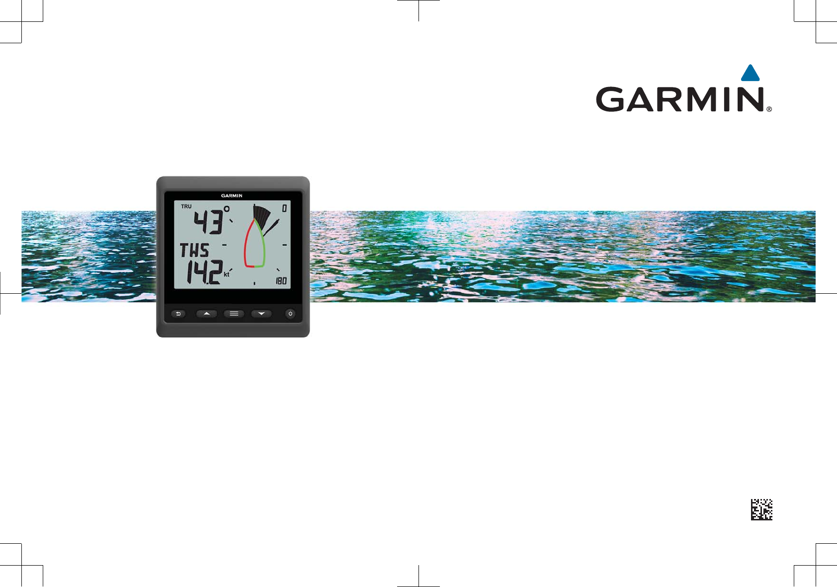
Instrument Screen
Item Description Notes
➀Upper data field Instrument screen: shows numeric wind angle or direction
information (page 6).
Menu screen: shows the decimal value of the menu category and
sub-menu item.
➁Wind rose Shows wind direction or angle information on the boat diagram.
(page 3)
➂Wind rose span Shows the scope of the wind rose, which changes when
configured for close-hauled sailing (page 3).
➃Lower data field Instrument screen: shows sensor speed information (page 6).
Menu screen: shows the name of the menu category or name and
value of the sub-menu item.
Viewing Sensor Information
The instrument shows sensor information using up to four instrument screens.
You can customize the number of instrument screens (page 6), and you can
customize the data shown on each instrument screen (page 6).
1When MENU or SUBMENU is shown, press repeatedly until you view an
instrument screen.
2Press and to move through the available instrument screens.
2Getting Started
Wind Rose
The wind rose shows a visual representation of the wind angle or direction
provided by the connected wind sensor.
You can configure the wind rose to show three types of wind information on an
instrument screen:
• Both the true wind angle and apparent wind angle at the same time
• A focused view for close-hauled sailing
• The true wind direction
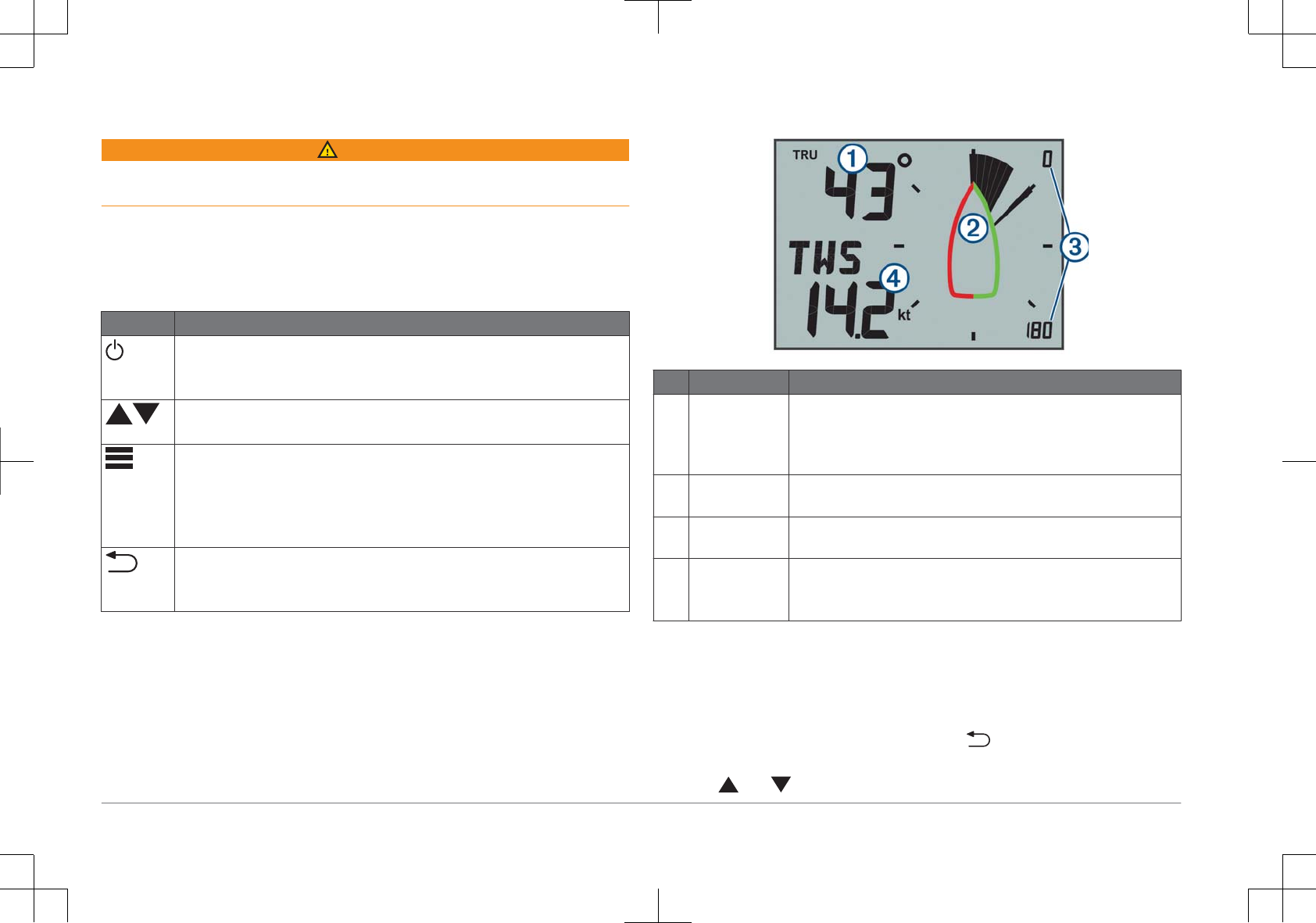
True and Apparent Wind Rose
When the center of the wind rose is empty, the wind rose shows both true and
apparent wind angles using two types of needles.
➀Shaded needle: the apparent wind angle (AWA)
➁Single needle: the true wind angle (TWA)
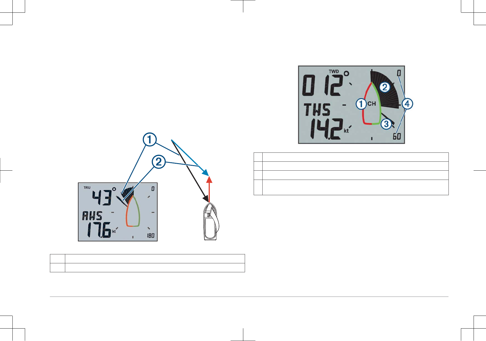
Close Hauled Wind Rose
When CH appears in the center of the wind rose, the wind rose shows both the
true and apparent wind angles in a focused section for close-hauled sailing.
➀CH: the wind rose is focused for close-hauled sailing.
➁Shaded needle: the apparent wind angle (AWA)
➂Single needle: the true wind angle (TWA)
➃Wind rose scale: the scope of the focused area, which adjusts automatically based on
the direction of the boat.
Wind Direction Wind Rose
When TWD appears in the center of the wind rose, the wind rose shows the true
wind direction using two types of needles.
Getting Started 3
➀TWD: the wind rose is showing the true wind direction.
➁Single needle: ithe direction the wind is coming from.
➂Double needle: the direction the wind is heading to.
Steer Pilot Mode
You can use the marine instrument to help you steer using a specific wind angle
or information received from connected sensors and a GPS device.
You can also use the marine instrument to help when tacking.
Using the Steer Pilot in AWA or TWA Mode
Before you can use the steer pilot in AWA mode, you must connect the
instrument to a wind sensor, either wirelessly or through the NMEA 2000®
network.
Before you can use the steer pilot in TWA mode, you must connect the
instrument to a wind sensor, either wirelessly or through the NMEA 2000
network, and you must connect it to a speed sensor or GPS device through the
NMEA 2000 network.
You can enter a specific wind-angle value and use the instrument as a steering
guide when sailing.
1From an instrument screen, hold .
The instrument enters steer-pilot mode.
2Select an option:
• If AWA or TWA is shown, proceed to step 4.
• If something other than AWA or TWA is shown, hold until the text
flashes.
3Press or to select AWA or TWA, and press .
4Press or to enter a numeric value for the wind angle to use when
steering.
5Press to confirm the wind angle.
6Steer the boat while keeping the needle pointing straight ahead.
Using Steer Pilot in BTW or CTS Mode
Before you can use the steer pilot in BTW mode, you must connect the
instrument to a GPS device through the NMEA 2000 network.
Before you can use the steer pilot in CTS mode, you must connect the instrument
to a GPS device, a heading sensor, and a speed sensor through the NMEA 2000
network.
You can use the instrument to help you steer to a waypoint on a connected GPS
device.
1Begin navigating to a destination on the connected GPS device.
2From an instrument screen, hold .
The instrument enters steer-pilot mode.
3Select an option:
• If BTW or CTS is shown, proceed to step 5.
• If something other than BTW or CTS is shown, hold until the text
flashes.
4Press or to select BTW or CTS, and press .
5Steer the boat while keeping the needle pointing straight ahead.
4 Steer Pilot Mode
Using Steer Pilot in MEM Mode
Before you can use the steer pilot in MEM mode, you must connect the
instrument to a heading sensor through the NMEA 2000 network.
The marine instrument can help you when tacking by using stored port and
starboard tack angles.
1From an instrument screen, hold .
The instrument enters steer-pilot mode.
2Select an option:
• If MEM is shown, proceed to step 4.
• If something other than MEM is shown, hold until the text flashes.
3Press or to select MEM, and press .
4Begin tacking port or starboard.
5After you make your first trim, push to store the heading value as MEM1.
6Continue tacking.
7After you make your second trim, push to store the heading value as
MEM2.
8Continue tacking while observing the needle.
When the needle moves from the center, it indicates the timing for the next
tacking maneuver.
The MEM1 and MEM2 values change automatically as you are tacking.
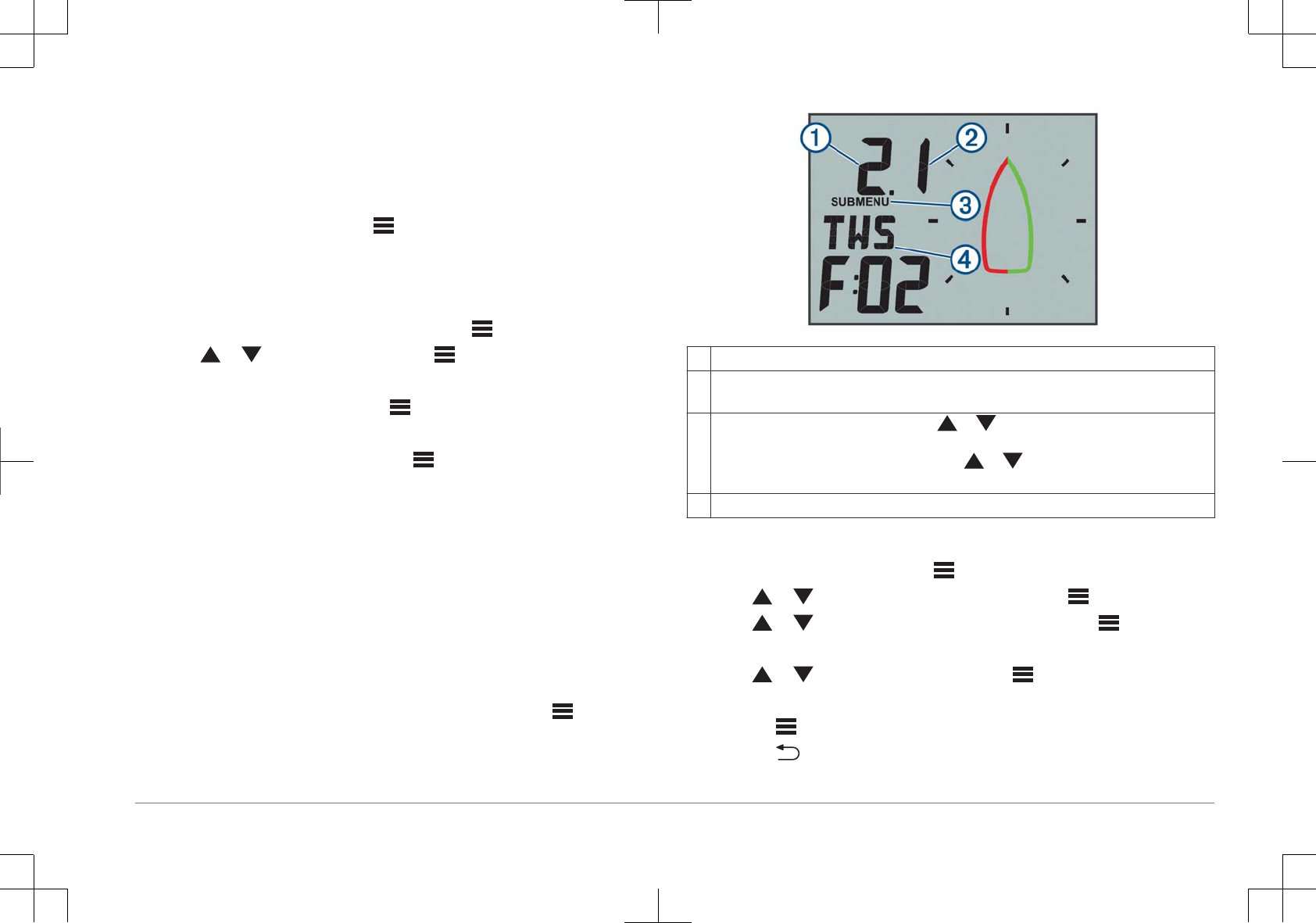
Configuration
You can configure the instrument displays and settings using the configuration
menu.
There are two levels in the configuration menu, indicated by the decimal value
that appears in the upper-left side of the screen when you press .
➀The value to the left of the decimal indicates the primary menu category.
➁The value to the right of the decimal indicates the sub-menu item within the primary
menu category.
➂When MENU is shown, you can press or to move through the primary menu
categories.
When SUBMENU is shown, you can press or to move through the sub-menu
items within the primary menu category.
➃The name of the primary menu category or sub-menu item.
Changing a Configuration Setting
1From an instrument screen, press .
2Press or to select a MENU category, and press .
3Press or to select a SUBMENU category, and press .
The value in the selected category flashes.
4Press or to adjust the value, and press to confirm the setting.
5Select an option:
• Press to confirm the new value and return to the SUBMENU category.
• Press to cancel all changes and return to the SUBMENU category.
The value in the selected category stops flashing.
Configuration 5
6Press two times to return to the instrument screens.
Adjusting the Number of Instrument Screens
You can customize a maximum of four instrument screens.
1From an instrument screen, press .
2Press or to select SYST, and press .
3Press or to select PGES, and press .
4Press or to select the number of instrument screens (1 through 4), and
press to confirm the setting.
5Press two times to return to the instrument screens.
Customizing an Instrument Screen
You can customize the data shown in the three main areas of each instrument
screen.
1From an instrument screen, press or to select an instrument screen to
customize.
2Press .
3Press to select DATA.
4Press or to select an option:
• Select SUBMENU 1.1 to change the lower-left (speed) value.
• Select SUBMENU 1.2 to change the upper-left (direction) value.
• Select SUBMENU 1.3 to change the wind rose function.
5Press .
6Press or to change the value.
7Press to confirm the change.
8Repeat steps 4 through 7 for every value or function you need to change on
the current instrument screen.
9Press two times to return to the instrument screens.
Configuration Menus
This section provides details for the items in the configuration menu, organized
by menu and sub-menu decimal values.
1.0 DATA Configuration Settings
1.1 Upper data field configuration: Changes the wind direction or angle type on
the current instrument page.
1.2 Lower data field configuration: Changes the speed type on the current
instrument page.
1.3 Wind rose configuration: Changes the function of the wind rose on the
current instrument page.
2.0 FILT Configuration Settings
In the filter configuration menu, you can adjust damping of the data received from
the sensor before it is shown in each data category (2.1 through 2.9).
The higher you set the update rate (0 through 9) for each data category, more the
data is dampened to remove the more extreme readings. For example, setting a
higher filter for TWS may provide a more stable wind-speed reading in gusty
conditions.
The glossary defines the data-type abbreviations used in this menu (page 7).
3.0 UNIT Configuration Settings
3.1 WIND: Changes the units of measure used for wind speed.
3.2 BSP: Changes the units of measure used for boat speed.
4.0 SENS Configuration Settings
4.1 ANGL: Adjusts the angle of the wind sensor to align with the front of the boat.
4.2 RSSI: Shows the signal strength between the instrument and the wireless
wind sensor.
4.3 WXDR: Turns data from the connected wireless wind sensor on or off. When
off, data from the connected wireless wind sensor is not transmitted over the
NMEA 2000 network.
4.4 BSP%: Adjusts the calibration of boat speed information shown on the
instrument.
6Configuration
NOTE: This adjustment affects the information as shown on the marine
instrument only. Other devices using speed information from the NMEA 2000
network must be calibrated separately, if needed.
5.0 SYST Configuration Settings
5.1 LGHT: Adjusts the backlight level on a scale of 0 through 100%.
5.2 COLR: Sets the color of the instrument display.
Settings C00 through C06 are the custom colors available locally on the
marine instrument.
Setting C07 is a custom-color setting controlled by other instruments on the
NMEA 2000 network.
5.3 BEEP: Tuns the key-press sounds on or off.
5.4 POWR: Allows you to change how the instrument turns on.
The AuT option turns the instrument on automatically when the NMEA 2000
network turns on.
The OFF option keeps the instrument off when the NMEA 2000 network turns
on. The instrument must be turned on by pressing .
5.5 PGES: Sets the number of instrument pages.
5.6 SCRL: Sets and adjusts your instrument screens to scroll automatically. The
value you set (0 through 9) represents the number of seconds between each
screen change.
A setting of 0 turns off scrolling.
5.7 DFLT: Restores the marine instrument to factory default settings.
5.8 VRSN: Shows the installed software version.
Appendix
Abbreviation Glossary
This device uses abbreviations on many screens to indicate the menu, setting, or
type of data being shown.
ALOG: (Analog sub menu) The filter sub menu that adjusts the dampening rate
for wind data on the wind rose.
ANGL: (Angle sub menu) The sensor sub menu that adjusts the wind-angle
offset of the data from the wind sensor.
APP: (Apparent Wind Angle) Shown in the upper-left data field. The wind angle
measured relative to the bow of the vessel.
AWA: (Apparent Wind Angle) The wind angle measured relative to the bow of the
vessel.
AWS: (Apparent Wind Speed) The measured speed of the wind.
BEEP: (Beep sub menu) The system sub menu that enables and disables key-
press sounds.
BSP: (Boat Speed) The speed of the boat through the water.
BSP%: (Boat speed sub menu) The sensor sub menu that adjusts the speed
data shown from a connected speed sensor.
BTW: (Bearing to Waypoint) The direction of travel towards a destination
waypoint.
COLR: (Color sub menu) The system sub menu that changes the color of the
instrument display.
CTS: (Course to Steer) Calculated course to a destination, compensating for drift.
DATA: (Data menu) The menu category containing instrument page
configuration items.
FILT: (Filter menu) The menu category containing data filter configuration items.
LGHT: (Backlight) The system sub menu that adjusts the backlight brightness
level.
MEM: (Memory - MEM1 and MEM2) Saved values for port and starboard, used
when tacking in steer pilot mode.
PGES: (Pages sub menu) The system sub menu that configures the number of
instrument screens shown.
POWR: (Power sub menu) The system sub menu that enables auto power-on.
Appendix 7
RSSI: (Signal strength sub menu) The sensor sub menu that shows the signal
strength between the instrument and the wireless wind sensor.
SENS: (Sensor menu) The menu category containing sensor configuration items.
STR: (Steer sub menu) The filter sub menu that adjusts the update rate for the
steering guide.
SYST: (System menu) The menu category containing system configuration
items.
TRU: (True Wind Angle) Shown in the upper-left data field. The angle of the wind,
compensated by the forward speed of the vessel.
TWA: (True Wind Angle) The angle of the wind, compensated by the forward
speed of the vessel.
TWD: (True Wind Direction) The true direction of the wind relative to north.
TWS: (True Wind Speed) The speed of the wind, compensated by the forward
speed of the vessel.
VMG: (Velocity Made Good ) See page 8.
WIND: (Wind sub menu) The unit sub menu that adjusts the units of measure
used to represent wind speed.
WXDR: (Wind transducer sub menu) The sensor sub menu that turns on and off
data from the connected wind sensor.
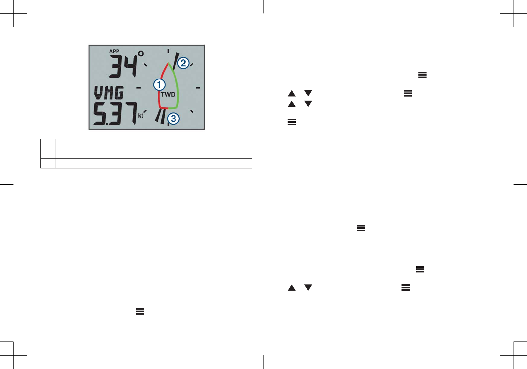
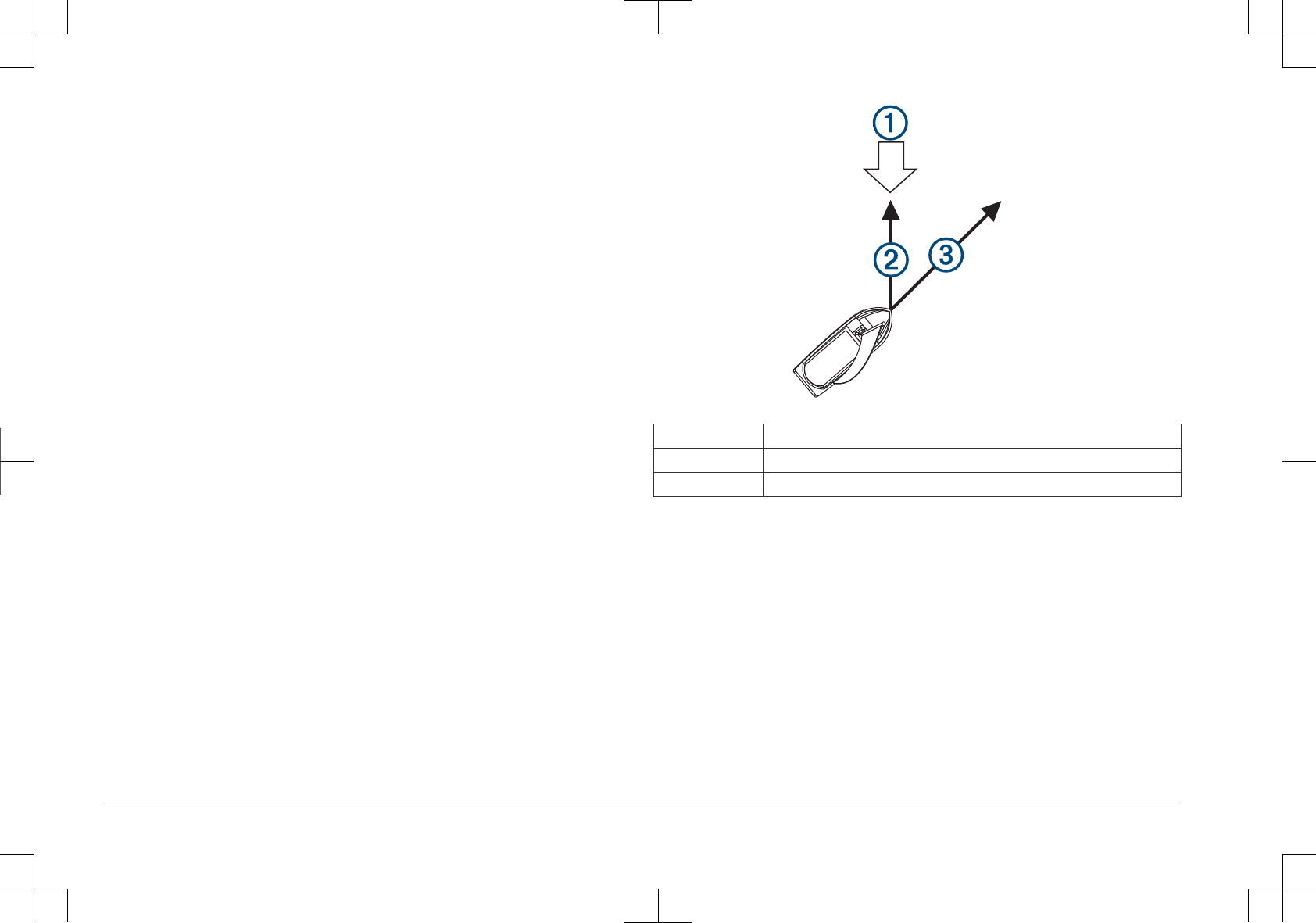
Velocity Made Good
Velocity made good (VMG) is the speed into or away from the wind. VMG is
calculated using boat-speed data from sensors on the NMEA 2000 network.
➀Wind direction
➁VMG
➂Boat speed
Contacting Garmin® Product Support
• Go to www.garmin.com/support for in-country support information.
• In the USA, call 913-397-8200 or 1-800-800-1020.
• In the UK, call 0808 238 0000.
• In Europe, call +44 (0) 870 850 1241.
8Appendix


www.garmin.com/support
1800 235 822 +43 (0) 820 220230
+ 32 2 672 52 54 0800 770 4960
1-866-429-9296 +385 1 5508 272
+385 1 5508 271
+420 221 985466
+420 221 985465 + 45 4810 5050
+ 358 9 6937 9758 + 331 55 69 33 99
+ 39 02 36 699699 (+52) 001-855-792-7671
0800 427 652 0800 0233937
+47 815 69 555 00800 4412 454
+44 2380 662 915
+35 1214 447 460 +386 4 27 92 500
0861 GARMIN (427 646)
+27 (0)11 251 9800 +34 93 275 44 97
+ 46 7744 52020 +886 2 2642-9199 ext 2
0808 238 0000
+44 870 850 1242
+49 (0) 89 858364880
zum Ortstarif - Mobilfunk
kann abweichen
913-397-8200
1-800-800-1020
Garmin® and the Garmin logo are trademarks of Garmin Ltd. or its subsidiaries, registered in the USA
and other countries. GNX™ is a trademark of Garmin Ltd. or its subsidiaries. These trademarks may not
be used without the express permission of Garmin.
NMEA 2000® and the NMEA 2000 logo are registered trademarks of the National Marine Electronics
Association.
© 2015 Garmin Ltd. or its subsidiaries