Contents
- 1. User manual (statement)
- 2. User manual
User manual
®
MS-RA55 Installation Instructions
Important Safety Information
WARNING
Failure to follow these warnings and cautions could result in personal injury,
damage to the vessel, or poor product performance.
See the Important Safety and Product Information guide in the product box for
product warnings and other important information.
This device must be installed according to these instructions.
Disconnect the vessel's power supply before beginning to install this product.
Before applying power to this product, make sure it has been correctly
grounded, following the instructions in the guide.
CAUTION
Always wear safety goggles, ear protection, and a dust mask when drilling,
cutting, or sanding.
NOTICE
When drilling or cutting, always check what is on the opposite side of the
surface.
You must read all installation instructions before beginning the installation. If
you experience difficulty during the installation, contact FUSION Product
Support.
What's In the Box
• Mounting gasket
• Four 6-gauge, self-tapping screws
• Power and speaker wiring harness
• Two screw covers
Tools Needed
• Phillips screwdriver
• Electric drill
• Drill bit (size varies based on surface material and screws used)
• Rotary cutting tool or jigsaw
• Marine sealant (optional)
Mounting Considerations
• The stereo must be mounted on a flat surface.
• The stereo must be mounted in a location that allows open airflow around
the rear of the stereo for heat ventilation.
• If you are installing the stereo in a location that may be exposed to water, it
must be mounted within 45 degrees of the horizontal plane.
• If you are installing the stereo in a location that may be exposed to water,
the cable should have a drip loop to allow water to drip down off the cable
and avoid damage to the stereo.
• If you need to mount the stereo outside a boat, it must be mounted in a
location far above the waterline, where it is not submerged.
• If you need to mount the stereo outside a boat, it should be mounted in a
location where it cannot be damaged by docks, pilings, or other pieces of
equipment.
• To avoid interference with a magnetic compass, the stereo should be
installed at least 15 cm (5.9 in.) away from a compass.
Mounting the Stereo
NOTICE
Be careful when cutting the hole to mount the stereo. There is only a small
amount of clearance between the case and the mounting holes, and cutting
the hole too large could compromise the stability of the stereo after it is
mounted.
Be careful when installing the stereo in an aluminum boat or a boat with a
conductive hull, if you require the electrical system to be isolated from the boat
hull.
Before you can mount the stereo in a new location on the mounting surface,
you must select a location in accordance with the mounting considerations.
1Trim the template and make sure it fits at the mounting location.
2Adhere the template to the mounting surface.
3Using a drill bit appropriate for the mounting surface, drill a hole inside the
corner of the dashed line on the template to prepare the mounting surface
for cutting.
4Using a rotary-cutting tool, cut the mounting surface along the inside of the
dashed line on the template.
5Place the stereo in the cutout to test the fit.
6If necessary, use a file and sandpaper to refine the size of the cutout.
7After the stereo fits correctly in the cutout, ensure the mounting holes on
the stereo line up with the pilot holes on the template.
8If the mounting holes on the stereo do not line up, mark the new pilot-hole
locations.
9Using an appropriately sized drill bit for the mounting surface and screw
type, drill the pilot holes.
10 Remove the template from the mounting surface.
11 Make the necessary wiring connections (Connections, page 1).
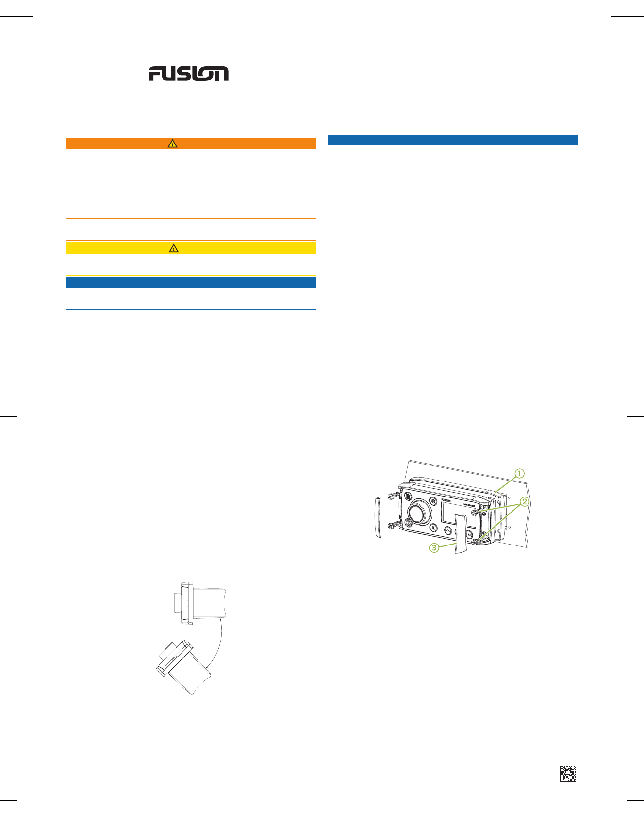
12 Place the mounting gasket on the back of the stereo À.
13 Place the stereo in the cutout.
14 Secure the stereo to the mounting surface using the included screws Á.
15 Snap the screw covers in place Â.
Connections
The stereo must be connected to power, to speakers, and to media input
sources to function correctly. You should carefully plan the layout of the
stereo, speakers, and your input sources before making any connections.
November 2016 Printed in Thailand 190-01934-02_01
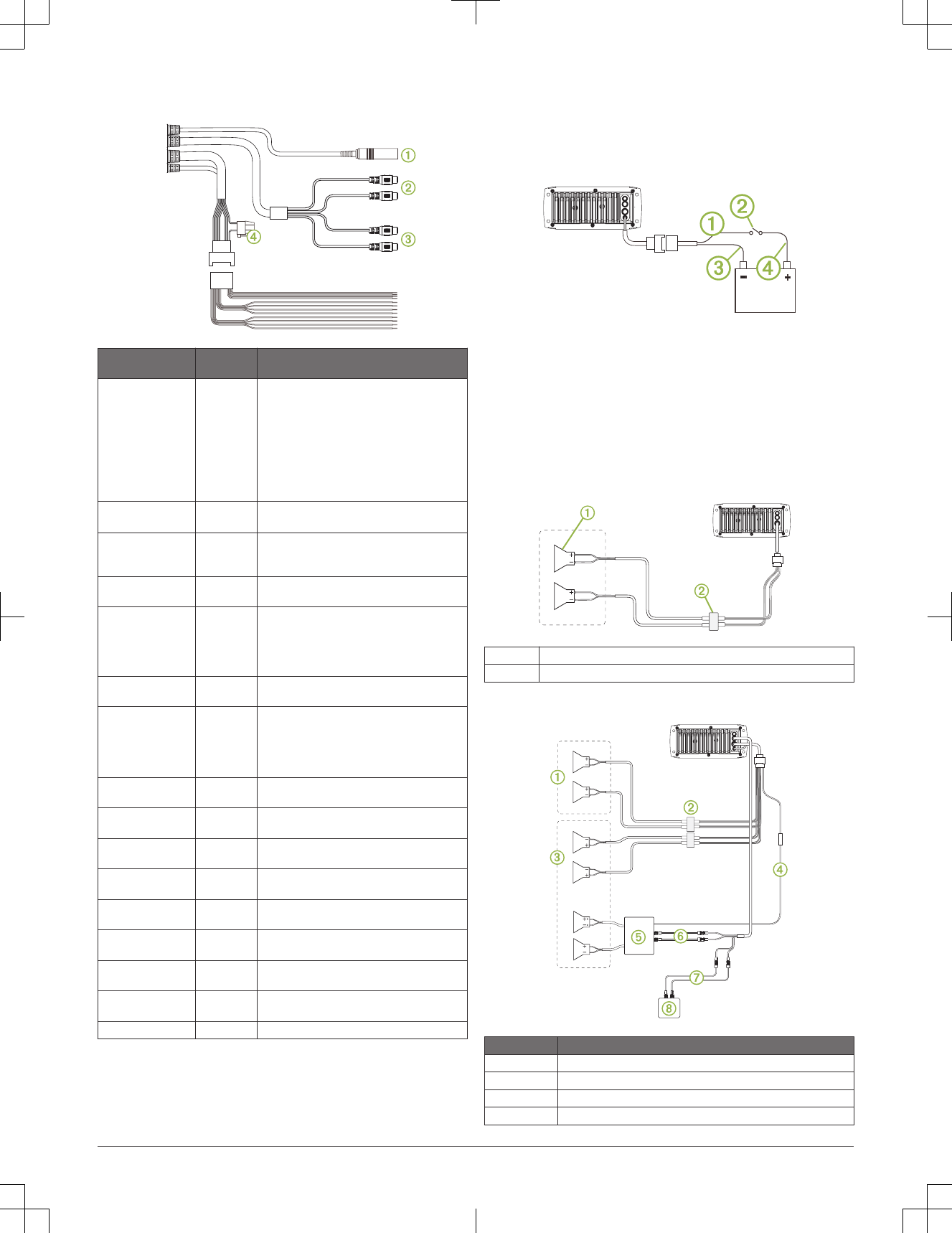
Wiring Harness Wire and Connector Identification
Wire Function Wire Color/
Number
Notes
Antenna ÀConnects the stereo to a typical AM/FM antenna
using an RF coaxial connector.
If you are installing the stereo on a boat with a
metal hull, you must use a ground-dependent
antenna, and if you are installing the stereo on a
boat with a non-metal hull, you must use a
ground-independent antenna. See the
installation instructions provided with your
antenna for more information.
Auxiliary in left
Auxiliary in right
ÁProvides a red and white RCA stereo line input
for audio sources, such as a CD or MP3 player.
Zone 1 line out (left)
Zone 1 line out (right)
ÂProvides a full-range output to an external
amplifier, and is associated with the volume and
tone for zone 1.
Power (+) Yellow Connects to the positive terminal of a 12 Vdc
power source capable of supplying 15 A.
Ground (-) Black Connects to the negative terminal of a 12 Vdc
power source. This wire should be connected
before connecting the yellow wire. All
accessories connected to the stereo must share
a common ground location.
Amplifier on Blue Connects to an optional external amplifier to turn
it on when the stereo turns on.
Dim Orange Connects to the boat's illumination wire to dim
the stereo screen when the lights are on.
The gauge of the illumination wire must be
suitable for the fuse supplying the circuit it is
connected to.
Speaker zone 1 left
(+)
White
Speaker zone 1 left
(-)
White/black
Speaker zone 1 right
(+)
Gray
Speaker zone 1 right
(-)
Gray/black
Speaker zone 2 left
(+)
Green
Speaker zone 2 left
(-)
Green/black
Speaker zone 2 right
(+)
Purple
Speaker zone 2 right
(-)
Purple/black
Fuse ÃContains the 15 A fuse.
Connecting to Power
When connecting the stereo to power, you should connect it through the
ignition or another manual switch.
If it is necessary to extend the power and ground wires, use 14 AWG
(2.08 mm2) wire. For extensions longer than 1 m (3 ft.), use 12 AWG
(3.31 mm2) wire.
1Route the power wire À to the ignition or another manual switch Á, and
route the black ground wire  to the battery.
2If necessary, route a wire à between the switch and the battery .
3Route the wiring-harness plug to the stereo.
Do not connect the wiring harness to the stereo until after all of the bare
wire connections have been made.
4Connect the black wire to the negative (-) battery terminal.
5Connect the power wire to the ignition or another manual switch, and
connect the switch to the positive (+) battery terminal if necessary.
6Connect the wiring harness plug to the stereo.
Single-Zone System Wiring Diagram
ÀSpeakers
ÁWater-tight connection
Complete System Wiring
Item Description
ÀZone 2 speakers
ÁWater-tight connection
ÂZone 1 speakers
ÃAmplifier-on signal wire
2 FUSION® MS-RA55 Installation Instructions
Item Description
ÄPowered amplifier
ÅZone 1 line out
ÆLine in cable
ÇAuxiliary line in device
Stereo Information
Specifications
General
Weight 556 g (19.6 oz.)
Water resistance IEC 60529 IPX5
Operating temperature range From 0 to 50°C (from 32 to 122°F)
Storage temperature range From -20 to 70°C (from -4 to 158°F)
Input voltage From 10.8 to 16 Vdc
Fuse 15 A
Current (max.) 15 A
Current (muted) Less than 350 mA
Current (standby) Less than 5 mA
Compass-safe distance 15 cm (5.9 in.)
On-board, Class AB Amplifier
Output music power per channel 45 W max. x 4 channels at 4 Ohms per channel
Total output music power 180 W max.
Tuner Europe and
Australasia
USA Japan
FM radio frequency
range
From 87.5 to 108 MHz From 87.5 to
107.9 MHz
From 76 to
95 MHz
FM frequency step 50 kHz 200 kHz 50 kHz
AM radio frequency
range
From 522 to 1620 kHz From 530 to
1710 kHz
From 522 to
1620 kHz
AM frequency step 9 kHz 10 kHz 9 kHz
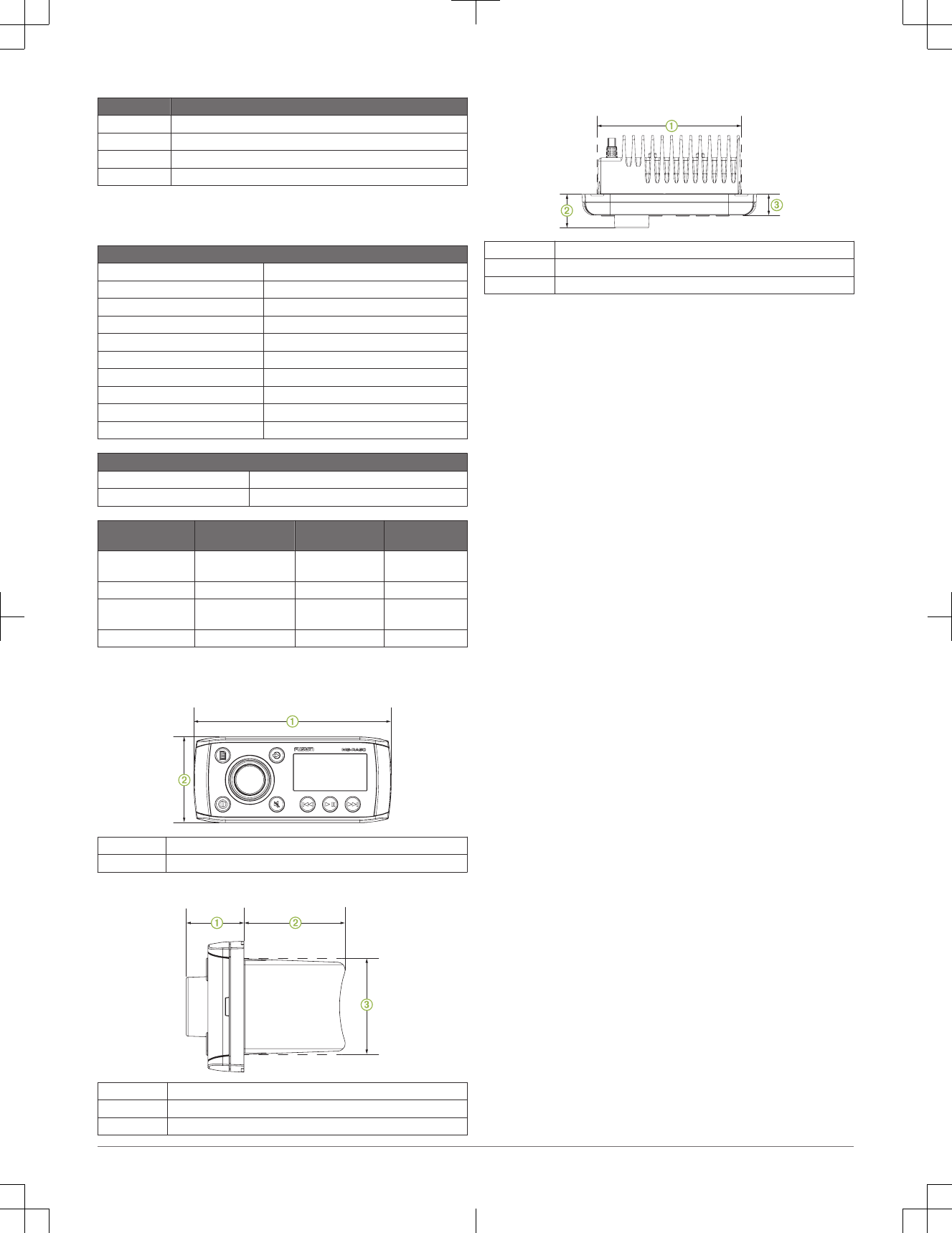
Stereo Dimension Drawings
Front Dimensions
À160 mm (6.3 in.)
Á71.5 mm (2.8 in.)
Side Dimensions
À32 mm (1.25 in.)
Á52 mm (2 in.)
Â50 mm (2 in.)
Top Dimensions
À130 mm (5.1 in.)
Á32 mm (1.25 in.)
Â20 mm (0.8 in.)
Reducing Unexpected Noise
If the stereo is subject to strong electrical interference, this interference might
be heard through the speakers. You should take appropriate action to
suppress or reduce the noise.
• Add clip-on ferrite beads to the cables connected directly to the product.
• Add clip-on ferrite beads to the device in the vessel that is causing the
interference.
• Disconnect the AUX input cable from the RCA connector when it is not
used.
• For additional information, go to www.fusionentertainment.com and
contact Tech Support.
Cleaning the Device
1Dampen a soft, clean, lint-free cloth with fresh water.
2Gently wipe the device.
Registering Your FUSION MS-RA55
Help us better support you by completing our online registration today.
• Go to www.fusionentertainment.com.
• Keep the original sales receipt, or a photocopy, in a safe place.
© 2016 Garmin Ltd. or its subsidiaries
Garmin®, the Garmin logo, FUSION®, and the Fusion logo are trademarks of Garmin Ltd.
or its subsidiaries, registered in the USA and other countries. These trademarks may not
be used without the express permission of Garmin.
Bluetooth® word mark and logos are owned by the Bluetooth SIG, Inc. and any use of
such marks by Garmin is under license. Other trademarks and trade names are those of
their respective owners.
FUSION® MS-RA55 Installation Instructions 3

© 2016 Garmin Ltd. or its subsidiaries www.garmin.com/support