Garmin 03450 Low Power Transmitter 2402-2480 MHz User Manual
Garmin International Inc Low Power Transmitter 2402-2480 MHz
Garmin >
Contents
- 1. User Manual
- 2. User Manual 1
User Manual
GRID™ 20
INSTALLATION
INSTRUCTIONS
Important Safety Information
WARNING
See the Important Safety and Product Information guide in the
product box for product warnings and other important
information.
When connecting the power cable, do not remove the in-line
fuse holder. To prevent the possibility of injury or product
damage caused by fire or overheating, the appropriate fuse
must be in place as indicated in the product specifications. In
addition, connecting the power cable without the appropriate
fuse in place voids the product warranty.
CAUTION
Always wear safety goggles, ear protection, and a dust mask
when drilling, cutting, or sanding.
NOTICE
When drilling or cutting, always check what is on the opposite
side of the surface.
To obtain the best performance and to avoid damage to your
boat, install the device according to these instructions.
Read all installation instructions before proceeding with the
installation. If you experience difficulty during the installation,
contact Garmin® Product Support.
Software Update
You must update the software when you install this device.
If your Garmin chartplotter has Wi‑Fi® technology, you should
update the software using the ActiveCaptain™ app on a
compatible Android™ or Apple® device. If your chartplotter does
not have has Wi‑Fi technology, you should update the software
using a memory card and a Windows® computer.
For more information, go to support.garmin.com.
Tools Needed
• Drill and drill bits
• #2 Phillips screwdriver
• Jigsaw or rotary tool
• File and sandpaper
• Marine sealant (optional)
Mounting and Connection Considerations
NOTICE
This device should be mounted in a location that is not exposed
to extreme temperatures or conditions. The temperature range
for this device is listed in the product specifications. Extended
exposure to temperatures exceeding the specified temperature
range, in storage or operating conditions, may cause device
failure. Extreme-temperature-induced damage and related
consequences are not covered by the warranty.
The mounting surface must be flat to avoid damaging the device
when it is mounted.
This device can be mounted in a dashboard or other surface
using the included hardware. When selecting a mounting
location, observe these considerations.
• To avoid interference with a magnetic compass, you must not
mount the device closer to a compass than TBD.
• You must mount the device in a location that allows room for
the routing and connection of the NMEA 2000® and power
cable or the replacement of the batteries.
• To connect wirelessly, you must mount the device within 3 m
(10 ft.) of the chartplotter.
Mounting the Device
NOTICE
Use only the included hardware when mounting this device.
Using mounting hardware not provided with the device may
damage the device.
Be careful when cutting the hole to flush mount the device.
There is only a small amount of clearance between the case and
the mounting holes, and cutting the hole too large could
compromise the stability of the device after it is mounted.
If you are mounting the device on fiberglass with screws, it is
recommended to use a countersink drill bit to drill a clearance
counterbore through only the top gel-coat layer. This will avoid
cracking in the gel-coat layer when the screws are tightened.
The included template and hardware can be used to mount the
device at the selected location. The nut plates and machine
screws allow you to more easily remove and replace the device
when you need to change the batteries.
1Trim the template and make sure it fits in the location where
you want to mount the device.
2Secure the template to the selected location.
3Using a XX mm (9/16 in.) drill bit, drill one or more of the holes
inside the corners of the solid line on the template to prepare
the mounting surface for cutting.
4Using a jigsaw or rotary tool, cut the mounting surface along
the inside of the solid line on the template.
5If necessary, use a file and sandpaper to refine the size of
the cutout.
6After the device fits correctly in the cutout, ensure the
mounting holes on the device line up with the larger 6 mm
(1/4 in.) holes on the template.
7If the mounting holes on the device do not line up, mark the
new hole locations.
8Using a 6 mm (1/4 in.) drill bit, drill the larger pilot holes.
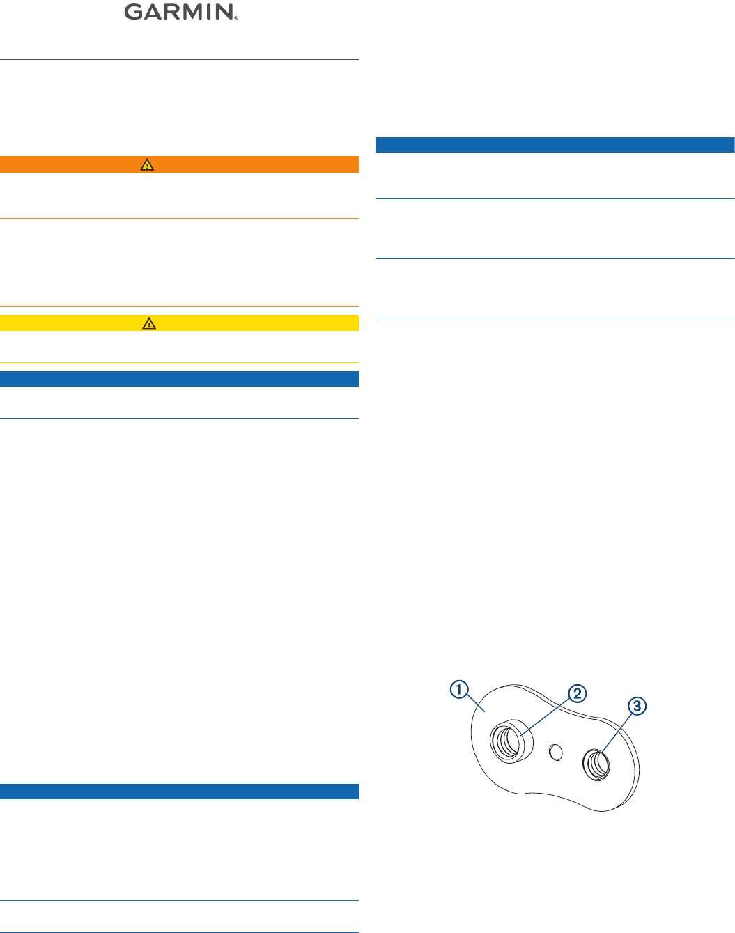
9Starting in one corner of the template, place a nut plate À
over the larger hole Á drilled in step 9.
The smaller hole  on the nut plate should line up with the
smaller 3.6 mm (9/64 in.) hole on the template.
10If the smaller hole on the nut plate does not line up with the
smaller hole on the template, mark the new hole location.
11Repeat for each nut plate.
12Using a 3.6 mm (9/64 in.) drill bit, drill the smaller holes.
13Remove the template from the mounting surface.
14Starting in one corner of the mounting location, place a nut
plate à on the back of the mounting surface, lining up the
large and small holes.
November 2018
190-02445-90_0A
DRAFT
The raised portion of the nut plate should fit into the larger
hole.
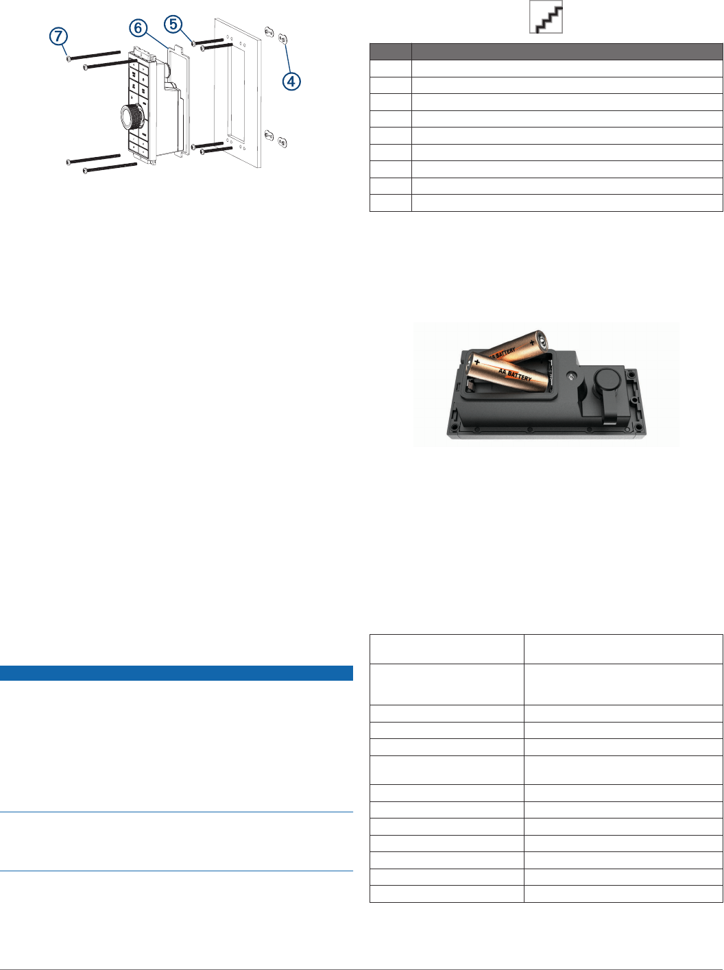
15Secure the nut plate to the mounting surface by fastening an
included M3 screw Ä through the smaller 3.6 mm (9/64 in.)
hole.
16Repeat for all 4 nut plates.
17Install the foam gasket Å on the back of the device.
The pieces of the foam gasket have adhesive on the back.
Make sure you remove the protective liner before installing
them on the device.
18If you will not have access to the back of the device after you
mount it, connect all necessary cables and install the AA
batteries (observing polarity) as needed before placing the
device into the cutout.
NOTE: To prevent corrosion of the metal contacts, if you are
not using the cable, firmly press the weather cap over the
connector.
19Apply marine sealant between the mounting surface and the
device to properly seal and prevent leakage behind the
dashboard.
20If you will have access to the back of the device, apply
marine sealant around the cutout.
21Place the device into the cutout.
22Secure the device to the mounting surface using the included
M4 screws Æ or wood screws, depending on the mounting
method.
23Carefully remove and discard the rubber protective bumper.
24Wipe away all excess marine sealant.
25Install the trim caps by snapping them in place around the top
and bottom of the device.
NMEA 2000 Connection Considerations
NOTICE
If you are connecting this device to an existing NMEA 2000
network, the NMEA 2000 network should already be connected
to power. Do not connect the NMEA 2000 power cable to an
existing NMEA 2000 network, because only one power source
should be connected to a NMEA 2000 network.
If you are connecting this device to an existing NMEA 2000
network or engine network by another manufacturer, you should
install a NMEA 2000 Power Isolator (010-11580-00) between
the existing network and the Garmin devices.
If you are installing a NMEA 2000 power cable, you must
connect it to the boat ignition switch or through another in-line
switch. NMEA 2000 devices will drain your battery if the NMEA
2000 power cable is connected to the battery directly.
The remote connects to a NMEA 2000 network on your boat,
which provides power to the remote. The included NMEA 2000
cable allows you to either connect the device to your existing
NMEA 2000 network.
If you need to create a NMEA 2000network and are unfamiliar
with it, go to support.garmin.com for more information.
Item Description
ÀGRID 20
ÁGarmin chartplotter
ÂIgnition or in-line switch
ÃNMEA 2000 power cable
ÄNMEA 2000 drop cable
Å12 Vdc power source
ÆNMEA 2000 terminator or backbone cable
ÇNMEA 2000 T-connector
ÈNMEA 2000 terminator or backbone cable
Installing the Batteries
You can use AA alkaline, NiMH, or lithium batteries. Use NiMH
or lithium batteries for best results.
1Turn the D-ring counter-clockwise, and pull up to open the
battery door.
2Insert two AA batteries, observing polarity.
NOTE: You should verify the gasket and battery
compartment are free of debris.
3Close the battery door, and turn the D-ring clockwise.
Pairing the GRID Device with the
Chartplotter from the Chartplotter
1Select Settings > System > Station Information > GRID™
Pairing > Add.
2On the GRID remote input device, press SELECT.
GRID 20 Specifications
Dimensions (W×H×D) 77 × 174.8 × 60 mm (31/16 × 67/8 ×
23/8 in.)
Material Fully gasketed, high-impact plastic,
waterproof to IEC 60529 IPX7
standards
Water resistance IEC 60529 IPX7*
Weight 258 g (9.1 oz.)
Temperature range From -15° to 70°C (from 5° to 158°F)
Battery type Two AA batteries (alkaline, NiMH, or
lithium)
Input power 10 to 35 Vdc
Fuse 7.5 A, 42 V fast-acting
Max. power usage at 10 Vdc 2.8 W
Typical current draw at 12 Vdc 100 mA
Max. current draw at 12 Vdc 280 mA
Compass-safe distance TBD
Wireless frequency/protocol 2.4 GHz @ TBD dBm nominal
*The device withstands incidental exposure to water of up to 1 m
for up to 30 min. For more information, go to www.garmin.com
/waterrating.
2
DRAFT

© 2018 Garmin Ltd. or its subsidiaries
Garmin® and the Garmin logo are trademarks of Garmin Ltd. or its subsidiaries,
registered in the USA and other countries. GRID™ is a trademark of Garmin Ltd. or its
subsidiaries. These trademarks may not be used without the express permission of
Garmin.
3
DRAFT

support.garmin.com
DRAFT