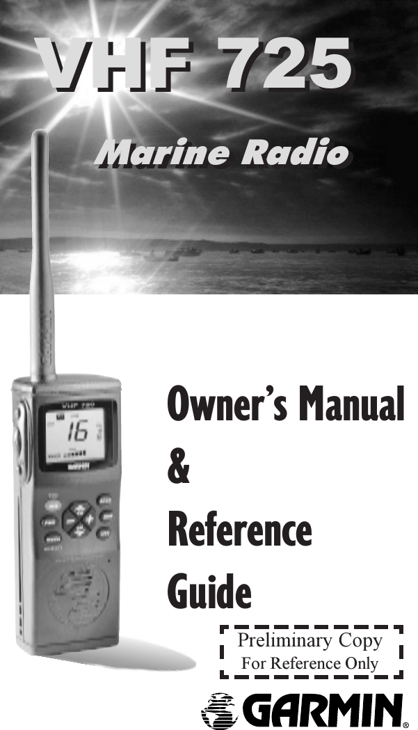
Garmin 37800 5 watt VHF Marine transciever User Manual VHF725Coverft p65
Garmin International Inc 5 watt VHF Marine transciever VHF725Coverft p65
UserManual.wiki
>
Garmin
>
37800 User Manual
>
VHF 725 User Manual
Contents
1.
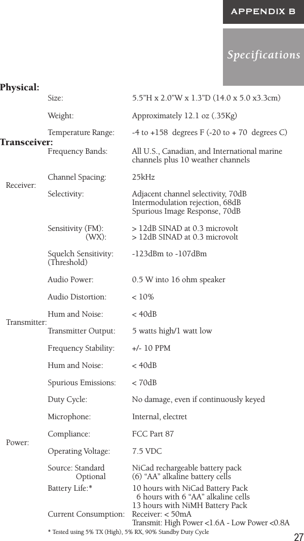
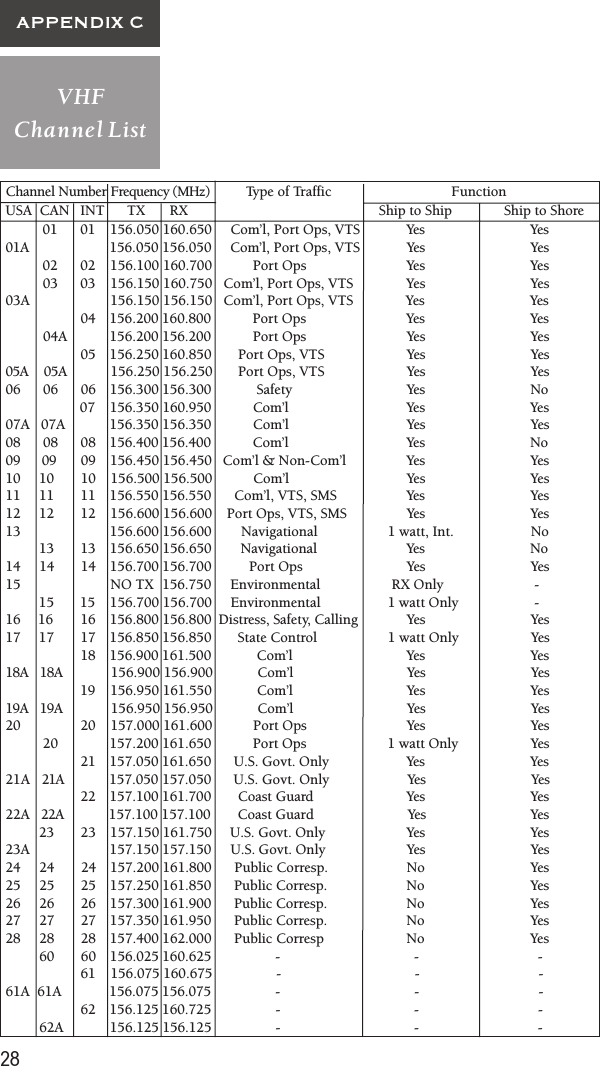
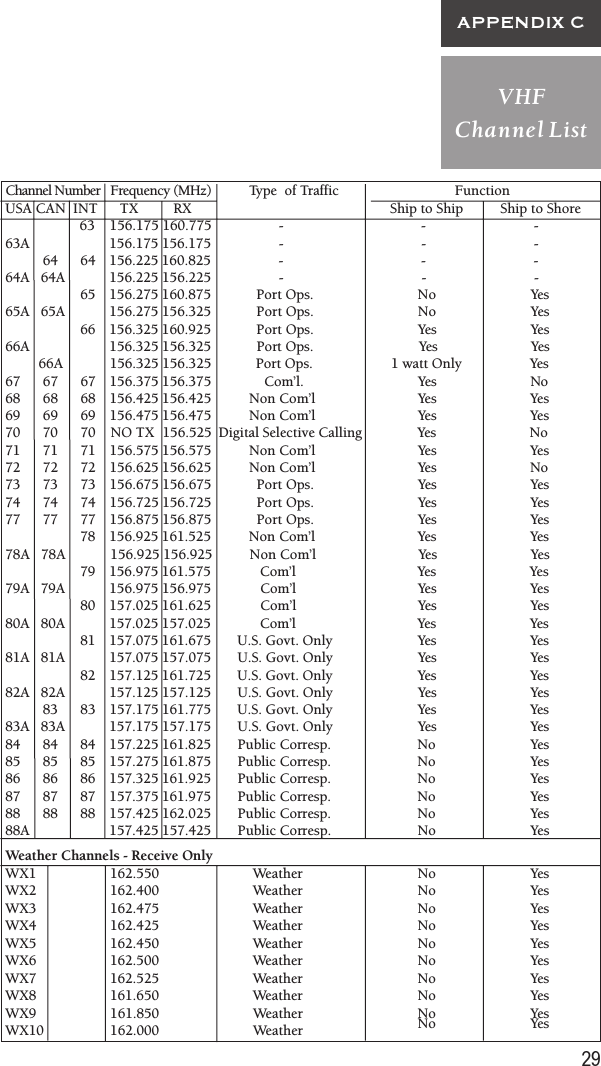
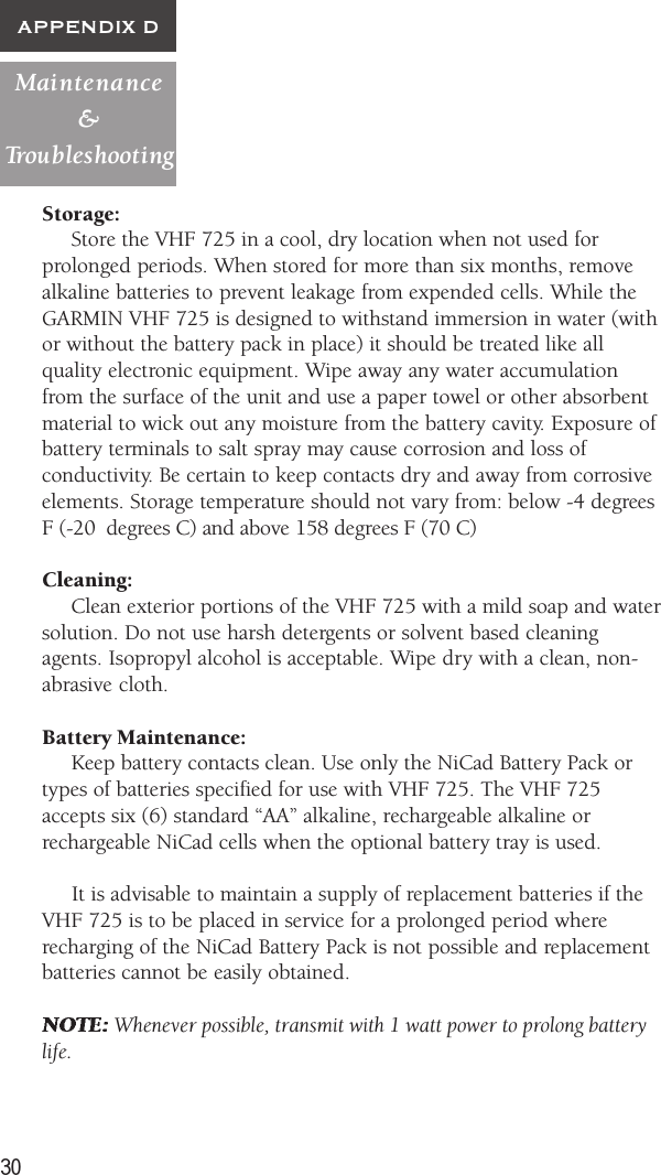
VHF 725 User Manual
2.
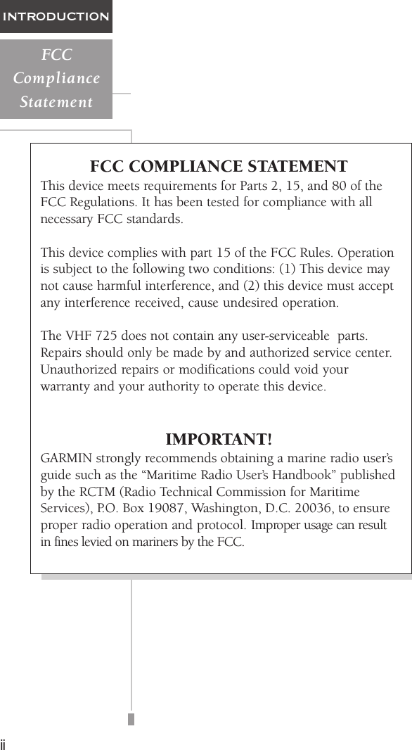
compliance statement
VHF 725 User Manual
Navigation menu
Upload a User Manual
Namespaces
Wiki Guide
HTML
PDF
Info
Views
User Manual
Discussion / Help
Navigation