Garmin 7XX 190 01007 A1_07 User Manual To The D0ffab8b D14d 4407 A4c4 C29a371239fb
User Manual: Garmin 7XX to the manual
Open the PDF directly: View PDF ![]() .
.
Page Count: 160 [warning: Documents this large are best viewed by clicking the View PDF Link!]
- Table of Contents
- List of Figures
- List of Tables
- 1 Introduction
- 2 System Description
- 3 GTN Control and Operation
- 4 Instructions For Continued Airworthiness
- 5 Troubleshooting
- 5.1 GTN General Troubleshooting
- 5.2 GTN Failure Annunciations
- 5.3 GTN System Messages
- 5.3.1 GTN System Related Alerts
- 5.3.1.1 COM Related Alerts
- 5.3.1.2 GPS/SBAS Related Alerts
- 5.3.1.3 VLOC/GS Related Alerts
- 5.3.1.4 Remote Transponder Related Alerts
- 5.3.1.5 GAD 42 Alerts
- 5.3.1.6 Traffic Related Alerts
- 5.3.1.7 Datalink Related Alerts
- 5.3.1.8 Weather Radar Alerts
- 5.3.1.9 TAWS Related Alerts
- 5.3.1.10 Third-Party Sensors Related Alerts
- 5.3.1 GTN System Related Alerts
- 5.4 Flight Stream Troubleshooting
- 5.5 GMA 35 Troubleshooting
- 5.6 GMA 35 Failure Annunciations
- 5.7 GMA 35 System Messages
- 6 Equipment Removal and Reinstallation
- 6.1 GTN
- 6.2 GMA 35
- 6.3 Data Card
- 6.4 Flight Stream 210
- 6.5 NAV Antenna Cable Diplexer
- 6.6 NAV Antenna Cable Splitter
- 6.7 Configuration Module (P1001 Only)
- 6.8 GTN Fan
- 6.9 TVS and Fuse (Nonmetallic Aircraft Only)
- 6.10 GPS/SBAS Antenna Cable Overbraid
- 6.11 WXR HSDB Cable Overbraid
- 6.12 Instrument Panel Bonding Strap
- 6.13 Flight Stream 210 Bonding Strap
- 7 Equipment Configuration and Testing
- 7.1 GTN 6XX/7XX
- 7.2 GMA 35
- 7.3 Configuration Module
- 7.4 Interfaced Equipment
- 7.5 Enabled Features
- 8 System Return to Service Procedure
- Appendix A Aircraft Specific Information

190-01007-A1 November 2014 Revision 7
System Maintenance Manual
GTN 6XX/7XX Part 23 AML STC
Contains Instructions for Continued Airworthiness
for STC SA02019SE-D
Aircraft Make, Model, Registration Number, and Serial
Number along with the applicable STC configuration
information must be completed in Appendix A and
saved with aircraft permanent records.

190-01007-A1 System Maintenance Manual GTN 6XX/7XX Part 23 AML STC
Rev. 7 Page A
© 2011-2014
Garmin International, Inc., or its subsidiaries
All Rights Reserved
Except as expressly provided herein, no part of this manual may be reproduced, copied, transmitted,
disseminated, downloaded or stored in any storage medium, for any purpose without the express prior
written consent of Garmin. Garmin hereby grants permission to download a single copy of this manual and
of any revision to this manual onto a hard drive or other electronic storage medium to be viewed and to
print one copy of this manual or of any revision hereto, provided that such electronic or printed copy of this
manual or revision must contain the complete text of this copyright notice and provided further that any
unauthorized commercial distribution of this manual or any revision hereto is strictly prohibited.
Adobe® is a registered trademark of Adobe Systems Incorporated. All rights reserved.
© 2014 The Bluetooth® word mark and logos are registered trademarks owned by Bluetooth SIG, Inc.
and any use of such marks by Garmin is under license. Other trademarks and trade names are those of
their respective owners.
© 2014 Sirius XM Radio Inc. Sirius, XM and all related marks and logos are trademarks of Sirius
XM Radio Inc. All other marks and logos are property of their respective owners. All rights reserved.
Garmin®, FliteCharts®, and SafeTaxi® are registered trademarks of Garmin International or its
subsidiaries. Connext™, Garmin Pilot™, GDU™, GTN™, and Telligence™ are trademarks of Garmin
International or its subsidiaries. These trademarks may not be used without the express permission of
Garmin.
At Garmin, we value your opinion.
For comments about this guide, please e-mail: Techpubs.Salem@garmin.com.
Garmin International Inc.
1200 E. 151st Street
Olathe, Kansas 66062 USA
Telephone: (913) 397-8200
www.garmin.com
Aviation Dealer Technical Support
Telephone (Toll Free): (888) 606-5482
Fax: (913) 397-0868
Fax (Toll Free): (800) 801-4670
E-mail: orders@garmin.com
avionics@garmin.com
warranty@garmin.com
Garmin AT, Inc.
2345 Turner Rd. SE
Salem, OR 97302 USA
Telephone: (503) 581-8101
Fax: (503) 364-2138
E-mail: support.salem@garmin.com
190-01007-A1
Rev. 7
System Maintenance Manual GTN 6XX/7XX Part 23 AML STC
Page B
Garmin (Europe) Ltd.
Liberty House, Hounsdown Business Park
Southampton, Hampshire SO40 9LR U.K.
Phone: +44 (0) 23 8052 4000
Fax: +44 (0) 23 8052 4004
Aviation Support +44 (0) 87 0850 1243
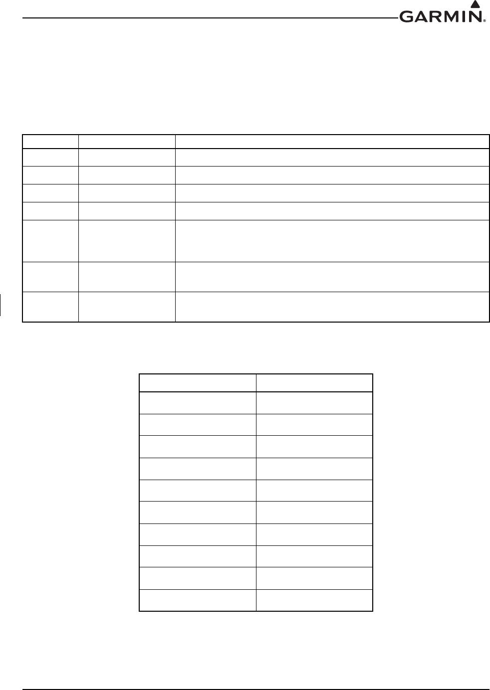
RECORD OF REVISIONS
DOCUMENT PAGINATION
Revision Revision Date Description
1 03/04/2011 Initial Release
2 01/18/2012 Added instructions for NAV antenna cable splitter and diplexer.
3 11/19/12 Reorganized to add maintenance instructions.
4 12/13/12 Removed ASR material and other minor edits.
5 3/25/2013
Revised to incorporate changes associated with GTN main software
version 4.10, COM software version 2.11, and GMA software version
3.05.
6 10/22/13 Revised to incorporate changes associated with GTN main software
version 5.00.
711/25/14 Revised to incorporate changes associated with GTN
main software version 5.13.
Section Pagination
Table of Contents ii through v
Section 1 1-1 through 1-4
Section 2 2-1 through 2-5
Section 3 3-1 through 3-19
Section 4 4-1 through 4-10
Section 5 5-1 through 5-22
Section 6 6-1 through 6-28
Section 7 7-1 through 7-24
Section 8 8-1 through 8-1
Appendix A A-1 through A-35
190-01007-A1
Rev. 7
System Maintenance Manual GTN 6XX/7XX Part 23 AML STC
Page i
INFORMATION SUBJECT TO EXPORT CONTROL LAWS
This document may contain information which is subject to the Export Administration Regulations
(“EAR”) issued by the United States Department of Commerce (15 Code of Federal Regulations (CFR),
Chapter VII, Subchapter C) and which may not be exported, released, or disclosed to foreign nationals
inside or outside of the United States without first obtaining an export license. A violation of the EAR may
be subject to a penalty of up to 10 years imprisonment and a fine of up to $1,000,000 under Section 2410
of the Export Administration Act of 1979. Include this notice with any reproduced portion of this
document.
This information in this document is subject to change without notice. Visit the Garmin web site
(www.garmin.com) for current updates and supplemental information concerning the operation of
Garmin products.
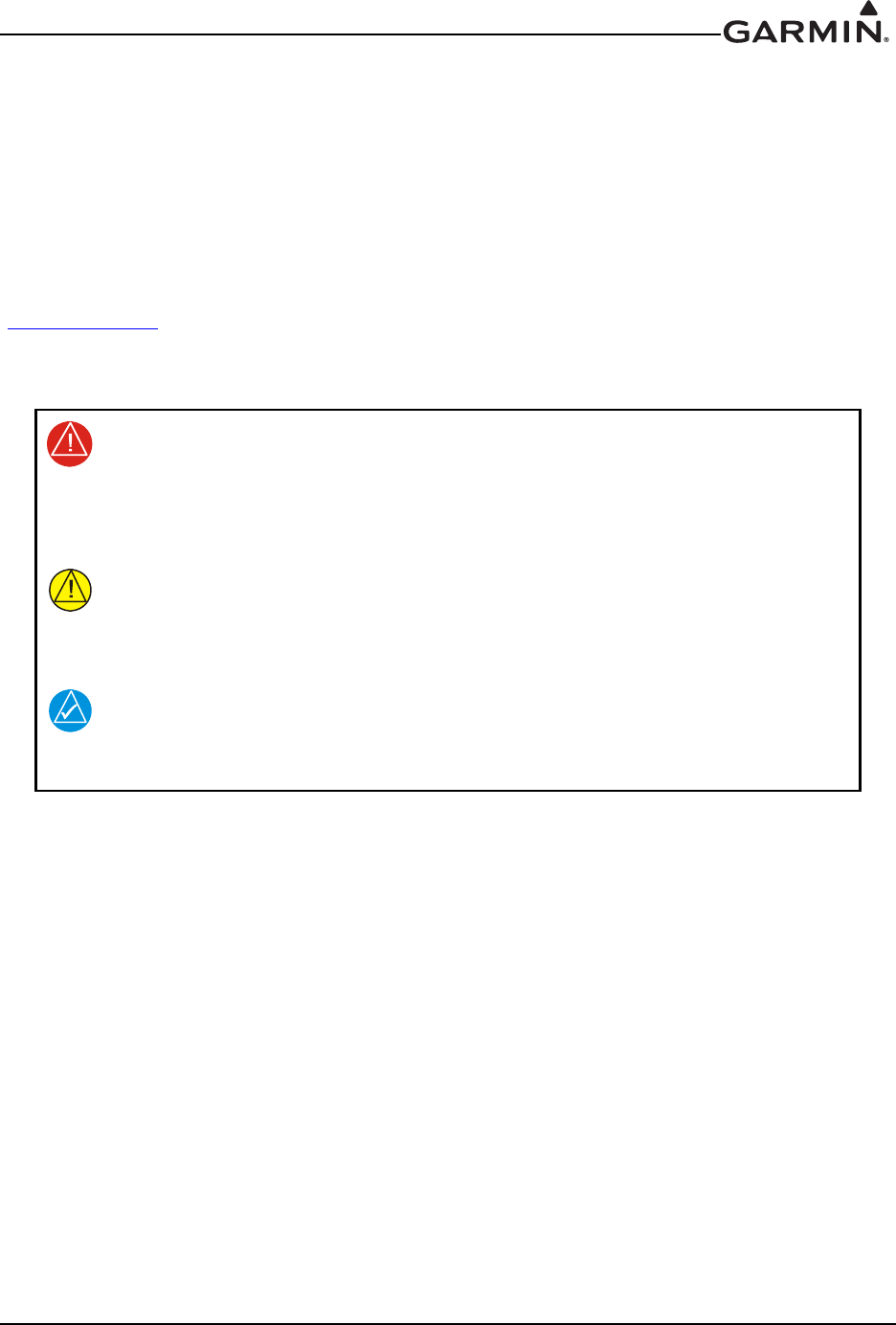
DEFINITIONS OF WARNINGS, CAUTIONS, AND NOTES
WARNING
Warnings are used to bring to the installer’s immediate attention that not only
damage to the equipment but personal injury may occur if the instruction is
disregarded.
CAUTION
Cautions are used to alert the individual that damage to equipment may result
if the procedural step is not followed to the letter.
NOTE
Notes are used to expand and explain the preceding step and provide further
understanding of the reason for the particular operation.

190-01007-A1
Rev. 7
System Maintenance Manual GTN 6XX/7XX Part 23 AML STC
Page ii
TABLE OF CONTENTS
1 INTRODUCTION..............................................................................................................................1-1
1.1 Content, Scope and Purpose.......................................................................................................1-1
1.2 Organization ...............................................................................................................................1-1
1.3 Definitions and Abbreviations ...................................................................................................1-2
1.4 Publications ................................................................................................................................1-3
1.5 Distribution.................................................................................................................................1-4
2 SYSTEM DESCRIPTION.................................................................................................................2-1
2.1 Equipment Descriptions .............................................................................................................2-1
2.2 Backplate Connectors.................................................................................................................2-2
2.3 GTN Optional Interfaces............................................................................................................2-4
2.4 GTN Block Diagram ..................................................................................................................2-5
3 GTN CONTROL AND OPERATION.............................................................................................3-1
3.1 GTN Controls.............................................................................................................................3-1
3.2 GTN Normal Mode Overview ...................................................................................................3-1
3.3 Software Loading .......................................................................................................................3-2
3.4 GTN Configuration Mode Overview .........................................................................................3-6
3.5 Database Updates .....................................................................................................................3-19
4 INSTRUCTIONS FOR CONTINUED AIRWORTHINESS.........................................................4-1
4.1 Airworthiness Limitations..........................................................................................................4-1
4.2 Servicing Information ................................................................................................................4-1
4.3 Maintenance Intervals ................................................................................................................4-2
4.4 Visual Inspection........................................................................................................................4-3
4.5 Electrical Bonding Test..............................................................................................................4-4
4.6 Transient Voltage Suppressor (TVS) (If Installed) ....................................................................4-8
4.7 GPS/SBAS Antenna Cable Overbraid Inspection (If Installed)...............................................4-10
4.8 WXR HSDB Cable Overbraid Inspection (If Installed)...........................................................4-10
5 TROUBLESHOOTING ....................................................................................................................5-1
5.1 GTN General Troubleshooting...................................................................................................5-1
5.2 GTN Failure Annunciations .......................................................................................................5-5
5.3 GTN System Messages ..............................................................................................................5-6
5.4 Flight Stream Troubleshooting.................................................................................................5-20
5.5 GMA 35 Troubleshooting ........................................................................................................5-21
5.6 GMA 35 Failure Annunciations...............................................................................................5-21
5.7 GMA 35 System Messages ......................................................................................................5-22
6 EQUIPMENT REMOVAL AND REINSTALLATION ................................................................6-1
6.1 GTN............................................................................................................................................6-1
6.2 GMA 35......................................................................................................................................6-5
6.3 Data Card....................................................................................................................................6-7
6.4 Flight Stream 210.......................................................................................................................6-8
6.5 NAV Antenna Cable Diplexer ...................................................................................................6-9
6.6 NAV Antenna Cable Splitter....................................................................................................6-10
6.7 Configuration Module (P1001 Only) .......................................................................................6-11
6.8 GTN Fan...................................................................................................................................6-14
6.9 TVS and Fuse (Nonmetallic Aircraft Only).............................................................................6-17
6.10 GPS/SBAS Antenna Cable Overbraid .....................................................................................6-21
6.11 WXR HSDB Cable Overbraid .................................................................................................6-23
6.12 Instrument Panel Bonding Strap ..............................................................................................6-26
6.13 Flight Stream 210 Bonding Strap.............................................................................................6-27

190-01007-A1
Rev. 7
System Maintenance Manual GTN 6XX/7XX Part 23 AML STC
Page iii
TABLE OF CONTENTS CONTINUED
7 EQUIPMENT CONFIGURATION AND TESTING.....................................................................7-1
7.1 GTN 6XX/7XX ..........................................................................................................................7-1
7.2 GMA 35......................................................................................................................................7-6
7.3 Configuration Module ..............................................................................................................7-10
7.4 Interfaced Equipment ...............................................................................................................7-10
7.5 Enabled Features ......................................................................................................................7-23
8 SYSTEM RETURN TO SERVICE PROCEDURE........................................................................8-1
8.1 Maintenance Records .................................................................................................................8-1
APPENDIX A AIRCRAFT SPECIFIC INFORMATION .................................................................A-1

190-01007-A1
Rev. 7
System Maintenance Manual GTN 6XX/7XX Part 23 AML STC
Page iv
LIST OF FIGURES
Figure 2-1. GMA 35 Connector Layout Detail - Rear View .....................................................................2-2
Figure 2-2. GTN 650 Connector Layout Detail - Rear View ....................................................................2-3
Figure 2-3. GTN 750 Connector Layout Detail - Rear View ....................................................................2-3
Figure 2-4. GTN System Interface Diagram .............................................................................................2-5
Figure 3-1. GTN 6XX Normal Mode Screen ............................................................................................3-1
Figure 3-2. GTN 7XX Normal Mode Screen ............................................................................................3-1
Figure 3-3. GTN Software Updater ...........................................................................................................3-2
Figure 3-4. System and Software Version .................................................................................................3-3
Figure 3-5. GTN Software Loader Card Formatting .................................................................................3-3
Figure 3-6. Update Progress Window .......................................................................................................3-4
Figure 3-7. Update Completion .................................................................................................................3-4
Figure 3-8. GTN 6XX and GTN 7XX Configuration Mode Pages ...........................................................3-6
Figure 3-9. GTN 7XX Updates Page .........................................................................................................3-7
Figure 3-10. System Information Page ......................................................................................................3-8
Figure 3-11. GTN 7XX Setup Pages .........................................................................................................3-9
Figure 3-12. GTN 7XX Options Pages ....................................................................................................3-11
Figure 3-13. GTN 7XX TAWS Configuration Page ...............................................................................3-12
Figure 3-14. Chart Configuration Page ...................................................................................................3-13
Figure 3-15. COM Transmit Power Configuration Page .........................................................................3-14
Figure 3-16. Weather Radar Page ............................................................................................................3-15
Figure 3-17. GTN 6XX and 7XX Diagnostics Pages ..............................................................................3-17
Figure 4-1. TVS Assembly Check .............................................................................................................4-9
Figure 5-1. Failure Screen .........................................................................................................................5-5
Figure 5-2. GMA 35 Failure Annunciation .............................................................................................5-21
Figure 6-1. GTN 7XX Mounting Rack Assembly .....................................................................................6-2
Figure 6-2. GTN 6XX Mounting Rack Assembly .....................................................................................6-3
Figure 6-3. GMA 35 Mounting Rack Assembly Overview ......................................................................6-6
Figure 6-4. Flight Stream Assembly Overview .........................................................................................6-8
Figure 6-5. Backshell Assembly (Potted Configuration Module) ...........................................................6-12
Figure 6-6. Backshell Assembly (Configuration Module with Spacer) ..................................................6-13
Figure 6-7. Fan/Backplate Orientation (GTN 7XX) ................................................................................6-14
Figure 6-8. Fan Wiring Replacement ......................................................................................................6-16
Figure 6-9. TVS/Fuse Replacement (TVS1/F1) ......................................................................................6-18
Figure 6-10. Detail of TVS Pin Assembly ...............................................................................................6-19
Figure 6-11. TVS2 Assembly ..................................................................................................................6-20
Figure 6-12. GPS/SBAS Antenna Cable Overbraid ................................................................................6-22
Figure 6-13. WXR HSDB Cable Overbraid Details ................................................................................6-24
Figure 6-14. Instrument Panel Bonding ...................................................................................................6-26
Figure 6-15. Flight Stream Bonding ........................................................................................................6-28
Figure 7-1. Audio Panel Page ....................................................................................................................7-6
Figure 7-2. Main Indicator (Analog) Configuration Page .......................................................................7-10
Figure 7-3. VOR/LOC/GS Configuration Page .......................................................................................7-11
Figure 7-4. XPDR1 Configuration Page ..................................................................................................7-18
Figure 7-5. Audio Configuration Page ....................................................................................................7-23
Figure 7-6. TAWS Configuration Page ...................................................................................................7-23

190-01007-A1
Rev. 7
System Maintenance Manual GTN 6XX/7XX Part 23 AML STC
Page v
LIST OF TABLES
Table 3-1. GTN Database Summary .......................................................................................................3-19
Table 4-1. Periodic Maintenance ...............................................................................................................4-2
Table 5-1. GTN Troubleshooting Guide ...................................................................................................5-1
Table 5-2. Alert Text Troubleshooting Guide ...........................................................................................5-6
Table 5-3. COM Alert Troubleshooting Guide .........................................................................................5-9
Table 5-4. GPS/SBAS Alert Troubleshooting Guide ..............................................................................5-11
Table 5-5. VLOC/GS Alert Troubleshooting Guide ...............................................................................5-12
Table 5-6. Remote Transponder Alert Troubleshooting Guide ...............................................................5-13
Table 5-7. GAD 42 Alert Troubleshooting Guide ...................................................................................5-14
Table 5-8. Traffic Alert Troubleshooting Guide .....................................................................................5-14
Table 5-9. Datalink Alert Troubleshooting Guide ...................................................................................5-15
Table 5-10. Weather Radar Alert Troubleshooting Guide ......................................................................5-17
Table 5-11. TAWS Alert Troubleshooting Guide ...................................................................................5-18
Table 5-12. Third-Party Sensor Alert Troubleshooting Guide ................................................................5-19
Table 5-13. Flight Stream Troubleshooting .............................................................................................5-20
Table 5-14. GMA 35 Troubleshooting ....................................................................................................5-21
Table 5-15. Remote Audio Panel Alert Troubleshooting Guide .............................................................5-22
Table 6-1. Self Test Values .......................................................................................................................6-4
Table 6-2. Configuration Module Wire Color Reference Chart ..............................................................6-11
Table 6-3. Configuration Module Kit 011-00979-03 (P1001) ................................................................6-12
Table 6-4. Configuration Module Kit 011-00979-00 (P1001) ................................................................6-13
Table 6-5. Fan Kit ....................................................................................................................................6-15
Table 6-6. Fan Cable Wire Color Reference Chart .................................................................................6-15
Table 6-7. Instrument Panel Bonding Hardware .....................................................................................6-26
Table 6-8. Flight Stream Bonding Hardware ..........................................................................................6-28
Table 7-1. Configuration and Checkout Procedures ..................................................................................7-2

190-01007-A1
Rev. 7
System Maintenance Manual GTN 6XX/7XX Part 23 AML STC
Page 1-1
1 INTRODUCTION
1.1 Content, Scope and Purpose
This document provides Instructions for Continued Airworthiness (ICA) for the GTN 6XX/7XX and
GMA 35 as installed under STC SA02019SE-D. This document satisfies the requirements for continued
airworthiness as defined by 14 CFR Part 23.1529 and 14 CFR Part 23 Appendix G. Information in this
document is required to maintain the continued airworthiness of the GTN 6XX/7XX, GMA 35, and Flight
Stream 210.
1.2 Organization
The following outline briefly describes the organization of this manual:
Section 2: System Description
Provides a description of the equipment installed by STC SA02019SE-D. An overview of the GTN and
GMA 35 system interface is also provided.
Section 3: GTN Control and Operation
Presents basic control and operation information specifically tailored to maintenance practices. Basic GTN
Configuration Mode operation is also described as well as loading of software.
Section 4: Instructions for Continued Airworthiness
This section provides maintenance instructions for continued airworthiness of the GTN and GMA 35
systems.
Section 5: Troubleshooting
This section provides troubleshooting information to aid in diagnosing and resolving potential problems
with the GTN and GMA 35 equipment.
Section 6: Equipment Removal and Reinstallation
This section provides instructions for the removal and reinstallation of the GTN and GMA 35 equipment.
Section 7: Equipment Configuration and Testing
This section provides instructions for the configuration and testing of the GTN and GMA 35 equipment.
Section 8: System Return to Service Procedure
This section specifies return-to-service procedures to be performed upon completion of maintenance of the
GTN and GMA 35 equipment.

190-01007-A1
Rev. 7
System Maintenance Manual GTN 6XX/7XX Part 23 AML STC
Page 1-2
1.3 Definitions and Abbreviations
The following terminology is used within this document:
AC: Alternating Current
ADS-B: Automatic Dependent Surveillance Broadcast
AGC: Automatic Gain Control
AGCS: Automatic Ground Clutter Suppression
AHRS: Altitude and Heading Reference System
AML: Approved Model List
BIT: Built-In Test
CDI: Course Deviation Indicator
CFR: Code of Federal Regulations
COM: Communications
CRG: Cockpit Reference Guide
CSA: Conflict Situational Awareness
DME: Distance Measuring Equipment
EFIS: Electronic Flight Instrument System
EHSI: Electronic Horizontal Situation Indicator
FIS-B: Flight Information Services Broadcast
FPGA: Field-Programmable Gate Array
G/S: Glideslope
GAD: Garmin Interface Adapter
GDL: Garmin Datalink
GMA: Garmin Audio Panel
GNS: Garmin Navigation System
GPS: Global Position System
GSR: Garmin Services
GTN: Garmin Touch Navigator
GWX: Garmin Weather Radar
HSDB: High-Speed Data Bus
ICA: Instructions for Continued Airworthiness
ICS: Intercom System
IFR: Instrument Flight Rules
ILS: Instrument Landing System
IRU: Inertial Reference Unit
LED: Light Emitting Diode
LOC: Localizer
LOI: Loss of Integrity
LRU: Line Replaceable Unit
MHz: Mega-Hertz
NAV: Navigation
OBS: Omni Bearing Selector
PA: Passenger Address

190-01007-A1
Rev. 7
System Maintenance Manual GTN 6XX/7XX Part 23 AML STC
Page 1-3
PED: Portable Electronic Device
PTC: Push-to-Command
PTT: Push-to-Talk
PVT: Position, Velocity, Time
R/T: Radar Transceiver
RF: Radio Frequency
RMI: Radio Magnetic Indicator
RX: Receive
SBAS: Satellite Based Augmentation System
SDI: Source/Destination Identifiers
SSM: Sign/Status Matrix
STC: Supplemental Type Certificate
TAS: Traffic Advisory System
TCAS: Traffic Collision Avoidance System
TAWS: Terrain Awareness System
TCAD: Traffic Collision Avoidance Device
TIS: Traffic Information Service
TSO: Technical Standard Order
TVS: Transient Voltage Suppressors
TX: Transmit
UTC: Coordinated Universal Time
VDC: Volts Direct Current
VFR: Visual Flight Rules
VHF: Very High Frequency
VOR: VHF Omni-directional Range
WAAS: Wide Area Augmentation System
WXR: Weather Radar
XPDR: Transponder
1.4 Publications
Part Number Garmin Document
005-00533-C0 Master Drawing List, GTN 6XX/7XX
005-00533-C1 GTN 6XX/7XX Equipment List
190-01007-A2 Supplemental Airplane Flight Manual for the Garmin GTN 6XX/7XX
GPS/SBAS Navigation System
190-01007-A5
Supplemental Airplane Flight Manual for Garmin GTN 6XX/7XX GPS/
SBAS Navigation System (GPS Functions Not Approved for IFR
Navigation)
190-01007-A3 GTN 6XX/7XX AML STC Installation Manual
190-01007-E1 GTN 6XX/7XX Installation Checklist

190-01007-A1 System Maintenance Manual GTN 6XX/7XX Part 23 AML STC
Rev. 7 Page 1-4
1.5 Distribution
This document is required for maintaining the continued airworthiness of the aircraft. When this document
is revised, every page will be revised to indicate the current revision level. Garmin Dealers may obtain the
latest revision of this document on the Garmin Dealer Resource Center website.
Owner/operators may obtain the latest revision of this document from www.flyGarmin.com or by
contacting a Garmin dealer. Other contacts include Garmin Product Support at 913-397-8200 (toll free
866-739-5687) or using around the world contact information on www.flyGarmin.com.
A Garmin Service Bulletin describing the revision to this document will be sent to Garmin dealers if the
revision is determined to be significant.

190-01007-A1 System Maintenance Manual GTN 6XX/7XX Part 23 AML STC
Rev. 7 Page 2-1
2 SYSTEM DESCRIPTION
2.1 Equipment Descriptions
2.1.1 GTN 6XX/7XX Navigators and GMA 35
The GTN SBAS navigators are a family of aviation panel mounted retro-fit products. The following
sections will describe the available functions for each unit in the GTN 6XX/7XX navigators.
2.1.1.1 GTN 6XX
The GTN 6XX SBAS navigators are a family of panel-mounted GPS/NAV/COM navigators.
The GTN 6XX units include the GTN 625, GTN 635, and GTN 650. They are 6.25" wide and 2.65" tall.
The GTN 6XX features a 600 by 266 pixel color LCD touchscreen. The GTN 625 is a GPS/SBAS unit that
meets the requirements of Technical Standard Order TSO-C146c and may be approved for IFR en route,
terminal, oceanic, non-precision, and precision approach operations when installed in accordance with the
instructions in the manuals referenced in the GTN AML STC. The
GTN 635 includes all of the features of the GTN 625 in addition to an airborne VHF communications
transceiver. The GTN 650 includes all of the features of the GTN 625 in addition to an airborne VHF
communications transceiver and airborne VOR/localizer (LOC) and glideslope (G/S) receivers.
2.1.1.2 GTN 7XX
The GTN 7XX SBAS navigators are a family of GPS/NAV/COM aviation panel-mounted products. The
GTN 7XX units include the GTN 725 and GTN 750. The GTN 7XX units are 6.25" wide and 6.00" tall.
They feature a 600 by 708 pixel color LCD touchscreen. The GTN 725 is a GPS/SBAS unit that meets the
requirements of Technical Standard Order TSO-C146c and may be approved for IFR en route, terminal,
oceanic, non-precision, and precision approach operations when installed in accordance with the
instructions in the manuals referenced in the GTN AML STC. The GTN 750 includes all of the features of
the GTN 725 in addition to an airborne VHF communications transceiver and airborne VOR/localizer
(LOC) and glideslope (G/S) receivers. The GTN 725 and 750 also have the ability to remotely control
GMA 35 audio panel functions.
2.1.1.3 GMA 35 Audio Panel
The GMA 35 audio panel is both a marker beacon receiver and an audio panel with 6-place intercom that
interfaces to the communications and navigation radios, headsets, microphones, and speakers. The
GMA 35 is remote-mounted and relies upon the GTN 725 or GTN 750 to control and display the audio
functions.
The GMA 35 interfaces to the GTN 7XX through RS-232 for control and display of audio panel functions.
Additionally, the GMA 35 includes a six-position intercom system (ICS) with electronic cabin noise de-
emphasis, two stereo music inputs, and independent pilot, copilot, and passenger volume controls. The
intercom provides three selectable isolation modes. A pilot-selectable cabin speaker output can be used to
listen to the selected aircraft radios or to broadcast PA announcements.
2.1.1.4 Flight Stream 210
The Flight Stream 210 brings Bluetooth® connectivity to the cockpit, allowing portable electronics to
stream data to and from the installed avionics.
The Flight Stream 210 interfaces to the GTN 6XX/7XX (Flight Stream supports connection to one
navigator at a time) through RS-232 for attitude information, flight plan information, and GPS PVT and
displays that information on a portable electronic device (PED). The Flight Stream may interface to the
GDL 88 through RS-422 and the GDL 69 through RS-232 as well.
190-01007-A1 System Maintenance Manual GTN 6XX/7XX Part 23 AML STC
Rev. 7 Page 2-2
2.1.2 NAV Antenna Cable Splitter
The navigation antenna cable splitter (Garmin P/N 013-00112-00) is used for installations involving dual
VHF navigation capable GTNs or a single VHF navigation capable GTN installation with a second
non-Garmin aviation unit.
2.1.3 NAV Antenna Cable Diplexer
The GTN 650/750 navigation units have a single navigation antenna port and thus require a composite
signal for those installations which include separate VOR/LOC and G/S antennas. The navigation diplexer
(Comant diplexer VOR/GS, Model CI-507) is used for these installations.
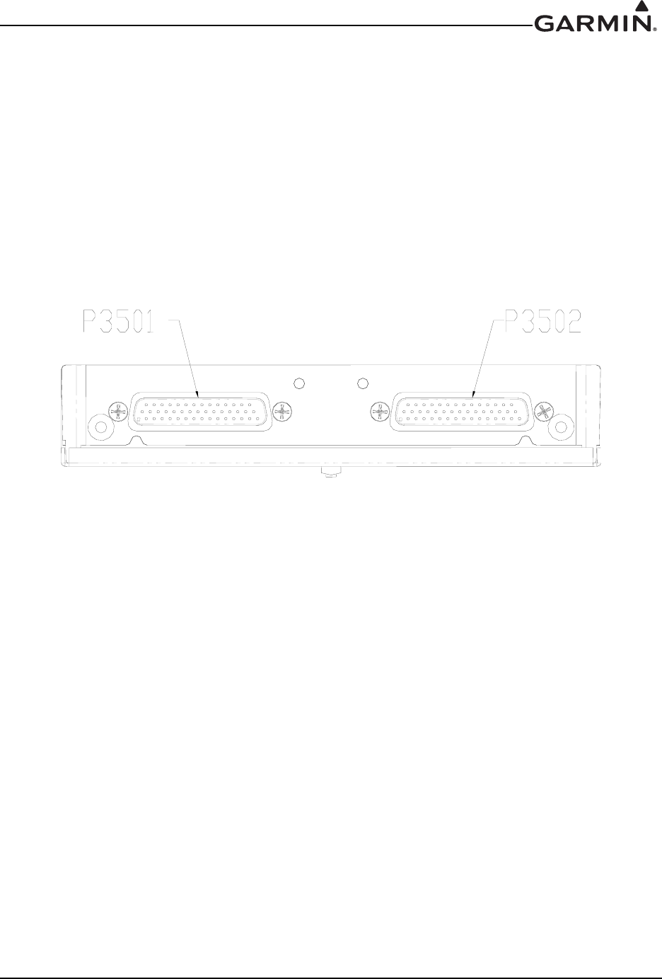
2.2 Backplate Connectors
Figure 2-1. GMA 35 Connector Layout Detail - Rear View
190-01007-A1 System Maintenance Manual GTN 6XX/7XX Part 23 AML STC
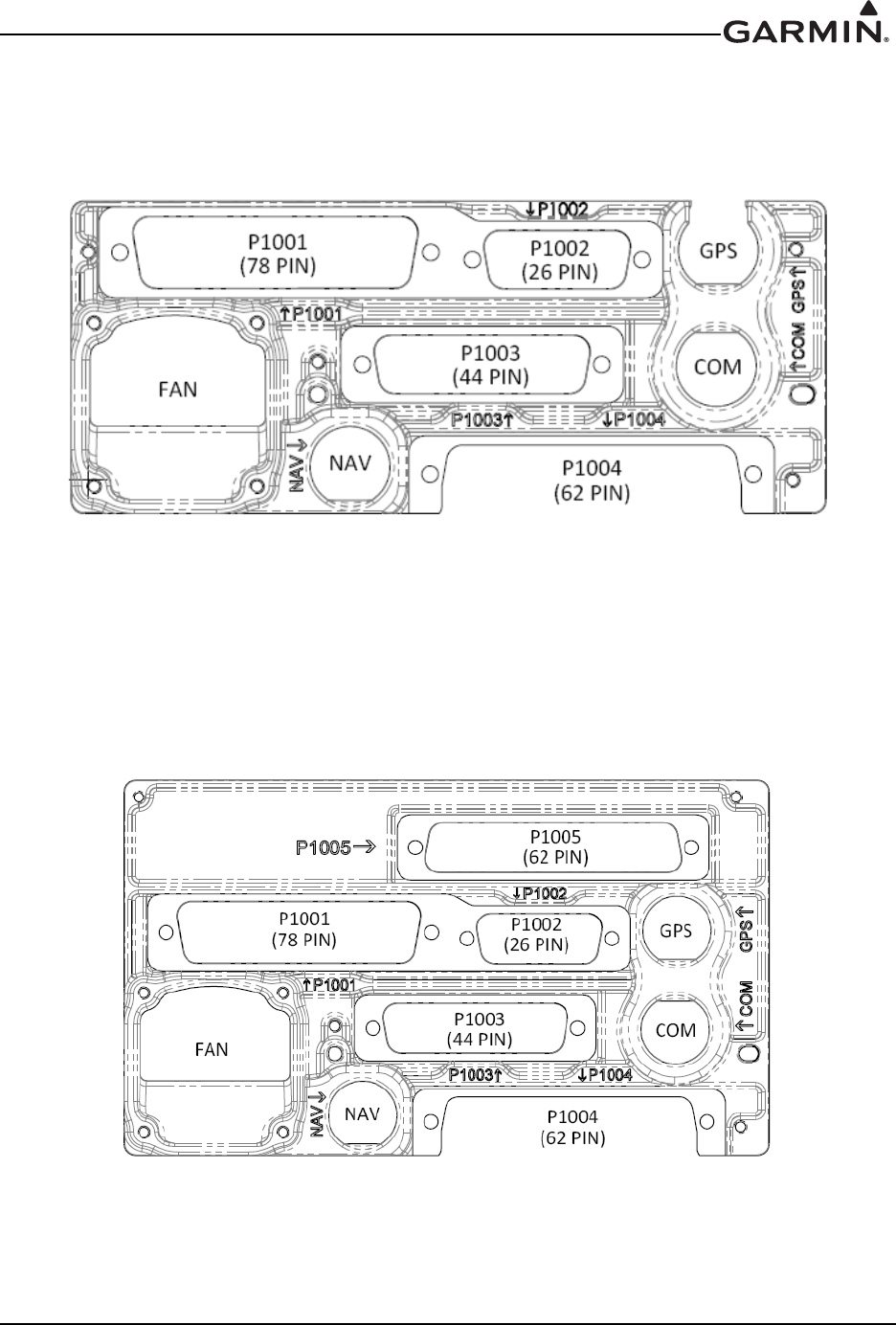
Rev. 7 Page 2-3
Figure 2-2. GTN 650 Connector Layout Detail - Rear View
Figure 2-3. GTN 750 Connector Layout Detail - Rear View

190-01007-A1 System Maintenance Manual GTN 6XX/7XX Part 23 AML STC
Rev. 7 Page 2-4
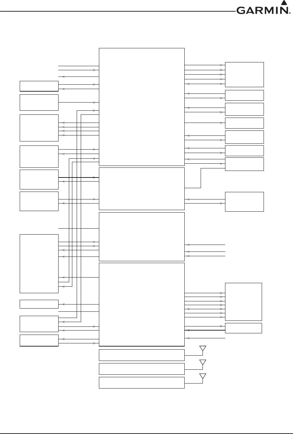
2.3 GTN Optional Interfaces
Optional equipment interfaces include:
Audio Panel
Air Data Computer
Altitude Serializer or Fuel/Air Data Computers
Autopilot
EFIS Displays
EHSI Displays
IRU/AHRS
Navigation Indicators
Weather, Traffic, Terrain Systems
DME
CDI/HSI Source Selection Annunciators
TAWS Annunciator Panels
Multifunction Displays
Interface Adapters
Synchro Heading Sources
Weather Radar
Garmin Iridium Transceiver
Garmin ADS-B Traffic and FIS-B Weather Sources
Garmin Flight Stream
190-01007-A1 System Maintenance Manual GTN 6XX/7XX Part 23 AML STC
Rev. 7 Page 2-5
2.4 GTN Block Diagram
Figure 2-4. GTN System Interface Diagram
*71;;;;
&211(&7253
32:(5*5281'
0$,1&',+6,
*36925,/6
6:,7&+(6
$1181&,$7256
(;7(51$/0$3
',63/$<
&',+6,
925,/621/<
.,1*6(5,$/
781(''0(
3$5$//(/781('
'0(
$5,1&
(),6(+6,
50,
$8',23$1(/
)/,*+7&21752/
6<67(0
)8(/$,5'$7$
25
6(5,$/,=(5
*$50,1
*71;;;;
&5266),//
/,*+7,1*%86
7,0(0$5.287
(7+(51(7,1
(7+(51(7287
56,1
$5,1&,1
$5,1&287
,/6*36$3352$&+
/$7'(9,$7,21)/$*6
72)520
9(57'(9,$7,21)/$*6
683(5)/$*6
0$,12%6
6:,7&+(6
$1181&,$7256
56287
(;7(51$/,167580(17$7,21
$,5&5$)732:(5*5281'
$,5&5$)7/,*+7,1*%86
*71;;;;
&211(&7253
&200,&.(<
&200,&$8',2
*71
&211(&7253
*71
&211(&7253
&205(027(75$16)(5 &205(027(75$16)(56:,7&+
&205(027(781(83 &205(027(781(
6:,7&+(6
&205(027(781('2:1
&20$8',2
9/2&$8',2
32:(5*5281'
$,5&5$)732:(5*5281'
9252%,
1$9$5,1&,1
1$9$5,1&287
32:(5*5281'
$,5&5$)732:(5*5281'
3$5$//(/'0(781,1*
1$9'0(&20021
1$95(027(75$16)(5 1$95(027(75$16)(56:,7&+
/$7'(9,$7,21)/$*6
72)520
9(57'(9,$7,21)/$*6
683(5)/$*6
9252%6
9/2&&20326,7(287
1$9,/6(1(5*,=(
6(5,$/'0(&/2&.'$7$
'0(5(48(67&20021
*71;;;;
&211(&7253
*366%$6$17(11$
*71
&211(&7253
&20$17(11$
*71
&211(&7253
1$9$17(11$
75$)),&
$5,1&,1
',6&5(7(6
672506&23(
56,1
56287
*65
56,1
56287
*16::
6(5,(6&5266),//
56,1
56287
$1$/2*$8',2
*$50,1
:($7+(55$'$5
(7+(51(7,1
(7+(51(7287
27+(5*$50,1/58V
(7+(51(7,1
(7+(51(7287
',6&5(7(6
/$7'(9,$7,21)/$*6
9(57'(9,$7,21)/$*6
683(5)/$*6
75$16321'(5
56,1
56287
56,1
56287
*71;;21/<
)/,*+7675($0
56,1
56287
*0$21/<
190-01007-A1 System Maintenance Manual GTN 6XX/7XX Part 23 AML STC
Rev. 7 Page 3-1
3 GTN CONTROL AND OPERATION
3.1 GTN Controls
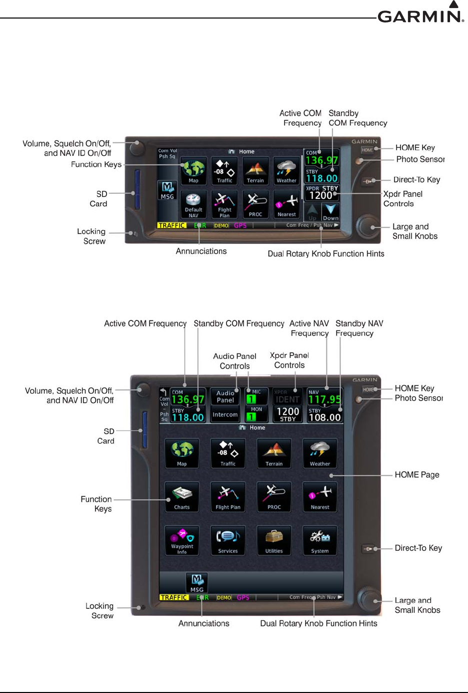
3.2 GTN Normal Mode Overview
Figure 3-1. GTN 6XX Normal Mode Screen
Figure 3-2. GTN 7XX Normal Mode Screen
190-01007-A1 System Maintenance Manual GTN 6XX/7XX Part 23 AML STC
Rev. 7 Page 3-2
3.3 Software Loading
3.3.1 GTN Software Loader Card Creation
A GTN Software Loader Card may be created using GTN Downloadable Software and an SD card in
conjunction with a GTN software application downloaded from the Dealer Resource Center on Garmin’s
website. The Dealer Resource Center will allow the technician to choose which software package(s) to
load onto the card.
NOTE
The downloadable application to create the GTN Software Loader Card only runs on PCs
with Windows. Windows 2000, XP, Vista, and Windows 7 are supported. There is no
Macintosh support at this time.
NOTE
An SD card reader is needed to create the GTN Software Loader card using the
application that is downloaded from Garmin. The approved readers are SanDisk®
SDDR-999 and SDDR-93, although other SD card readers will work.
Create a GTN Software Loader Card as follows:
1. Go to the Dealer Resource Center on Garmin’s website.
2. Download the GTN Software Loader Image. Refer to the Equipment List (P/N 005-00533-C1) for
the correct Software Loader Image part number.
3. Ensure that you have an SD card reader connected to the PC. Insert the GTN Downloadable
Software SD Card into the card reader.
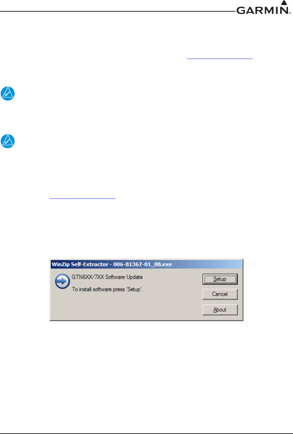
4. Run the executable file. The screen shown in Figure 3-3 will appear.
Figure 3-3. GTN Software Updater
5. Click Setup. The window shown in Figure 3-4 will appear to guide you through the software
loader card creation process.
190-01007-A1 System Maintenance Manual GTN 6XX/7XX Part 23 AML STC
Rev. 7 Page 3-3
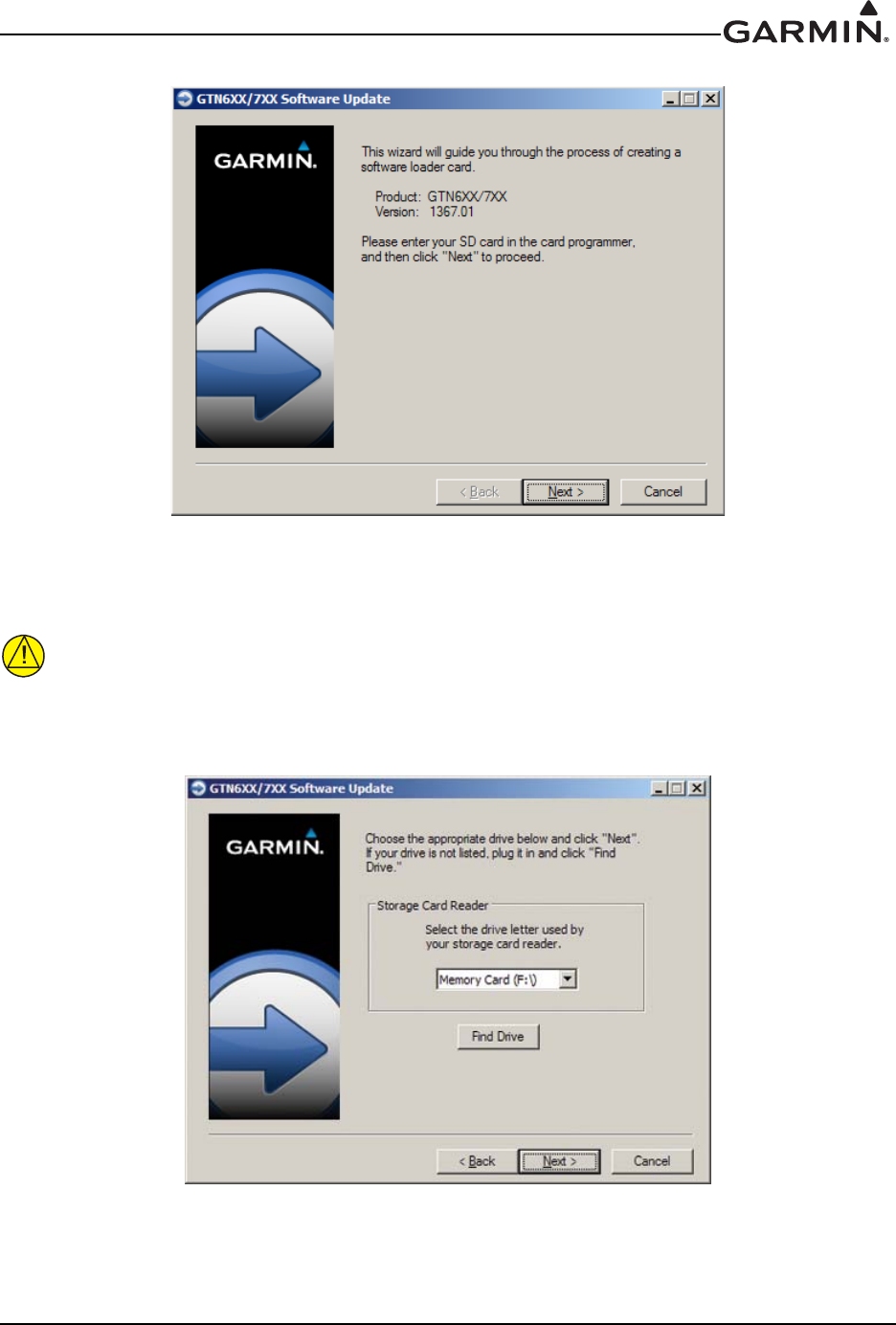
Figure 3-4. System and Software Version
6. Click Next and the window shown in Figure 3-5 will appear.
CAUTION
In order to create a GTN Software Loader Card, the drive that you select will be
completely erased.
Figure 3-5. GTN Software Loader Card Formatting
190-01007-A1 System Maintenance Manual GTN 6XX/7XX Part 23 AML STC
Rev. 7 Page 3-4
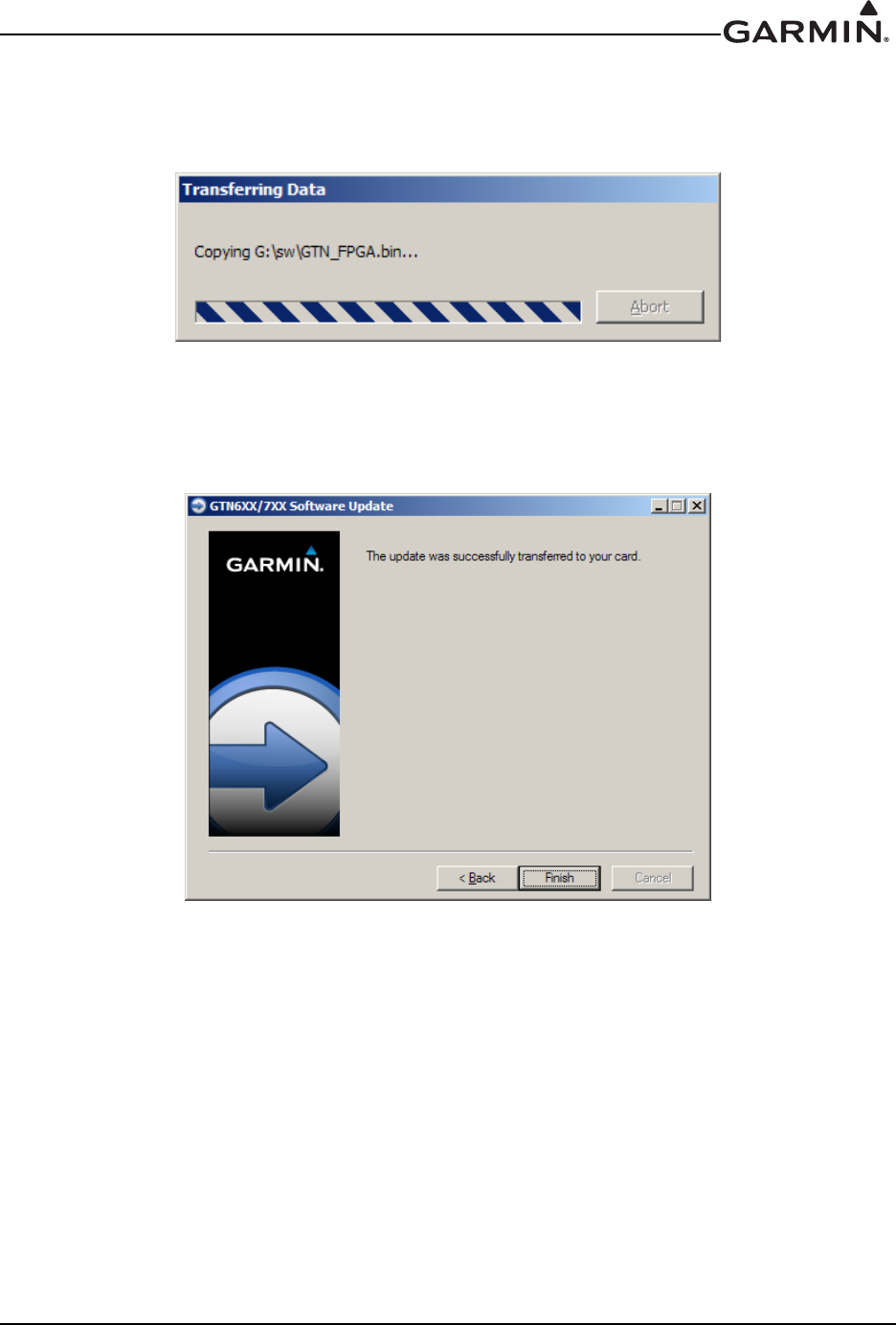
7. Ensure that the correct drive is selected. Click Next to create the card. Click Next to acknowledge
any warnings that appear. The progress window in Figure 3-6 will appear when the card is being
created.
Figure 3-6. Update Progress Window
8. After the card has been created, the window shown in Figure 3-7 in will appear. Click Finish to
complete the update process.
Figure 3-7. Update Completion
9. Eject the card from the card reader (or stop the card reader in Windows). The GTN Software
Loader Card is now ready to use.

190-01007-A1 System Maintenance Manual GTN 6XX/7XX Part 23 AML STC
Rev. 7 Page 3-5
3.3.2 GMA 35 Software Loading
NOTE
The GMA 35 software will be present on the SD card when creating a GTN Software
Loader Card. A separate card is not required to perform GMA 35 software updates.
1. Remove power from the GTN 7XX by opening the circuit breaker
2. Insert the GTN Software Loader Card into the GTN 7XX data card slot (See Section 3.3.1 for
instructions on how to create a GTN Software Loader Card).
3. Hold down the HOME key until Garmin is fully lit on the display after power is applied by
closing the circuit breaker for the GTN 7XX.
4. Ensure the GMA 35 circuit breaker is also closed.
5. The Configuration Mode page should now be displayed. Touch the Updates key to display the
software that is available.
6. To select GMA 35 software updates, touch the GTN Software Updates key on the top left corner
of the display and select GMA 35 Software Updates.
7. To update the GMA 35 with all software available, touch Select All.
8. To begin the software update, touch the Update key on the bottom of the display.
9. The GTN will display the prompt, ‘Start GMA 35 Software Updates?’
10. Touch OK to allow the GTN to update the GMA 35.
11. When the updates are finished, the GTN will display ‘Update Complete!’
12. When finished, turn the GTN and GMA 35 off (open the circuit breaker) and remove the Software
Loader Card. Reinsert the database card in the data card slot.
13. Restore power on the GTN and GMA 35 by closing the circuit breakers and ensure the software
was updated correctly by going to the System Information page and selecting the GMA 35. Refer
to Section 3.4.2 for more information on the System Information page.
190-01007-A1 System Maintenance Manual GTN 6XX/7XX Part 23 AML STC
Rev. 7 Page 3-6
3.4 GTN Configuration Mode Overview
NOTE
When configuring the GTN, ensure that no configuration module service messages are
displayed in the message queue. This would indicate that the configuration module is
improperly wired or damaged.
Configuration mode is used to configure the GTN settings for each specific installation. To access
configuration mode, perform the following steps:
1. Remove power from the GTN by opening the circuit breaker.
2. Press and hold the HOME key and reapply power to the GTN (push in the circuit breaker).
3. Release the HOME key when the display activates and the name ‘Garmin’ appears fully lit on the
screen.
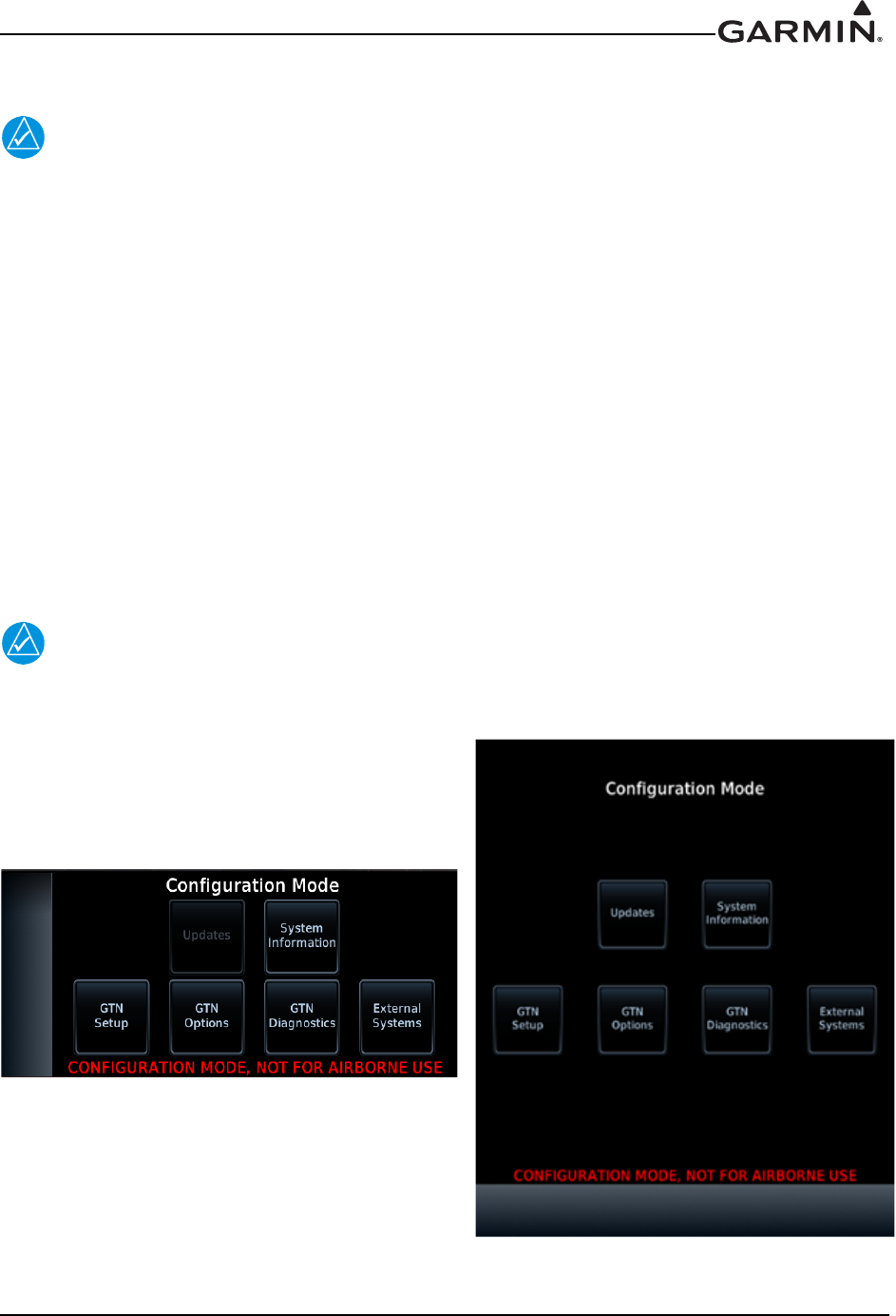
The first page displayed is the Configuration Mode page, as shown in Figure 3-8. For detailed information
regarding how to configure the GTN, refer to the GTN 6XX/7XX AML STC Installation Manual,
P/N 190-01007-A3. While in configuration mode, pages can be selected by touching the desired key on the
display. Some pages may require page scrolling to view all of the information and keys on the page.
Scrolling is done by touching the screen and dragging the page in the desired direction, or by touching the
Up or Down keys.
NOTE
The configuration pages shown here reflect main software version 3.00. Some differences
in operation may be observed when comparing information in this manual to later
software versions.
Figure 3-8. GTN 6XX and GTN 7XX Configuration Mode Pages
190-01007-A1 System Maintenance Manual GTN 6XX/7XX Part 23 AML STC
Rev. 7 Page 3-7
3.4.1 GTN Software Updates
NOTE
The following steps will need to be repeated for each replacement GTN unit that requires a
software update.
To update the GTN software, perform the following steps:
1. Remove power from the GTN by opening the circuit breaker.
2. Remove the database card and insert the correct GTN Software Loader Card into the data card slot.
See Section 3.3.1 for creating a GTN Software Loader Card.
3. Restore power to the GTN by closing the circuit breaker.
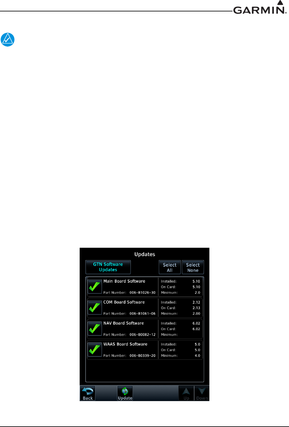
4. The GTN is now in configuration mode as shown in Figure 3-8. Touch Updates to display the
software updates that are available.
5. Check that the software version being loaded to the GTN matches the software version listed on
the GTN STC Equipment List, 005-00533-C1. The Updates page displays the version that is
installed on the unit and the version installed on the loader card.
6. Check that the available GTN software updates are being displayed by ensuring that GTN
Software Updates key is highlighted in the upper left corner (upper right corner for 6XX) of the
display.
7. To update the GTN with all software available, touch Select All.
8. To begin the software update, touch Updates on the bottom of the display.
9. The GTN will display the prompt, ‘Start GTN Software Updates?’
10. Touch OK to allow the GTN to go through the update process.
11. When the updates are finished, the GTN will display ‘Update Complete!’ When finished, remove
power from the GTN and remove the Software Loader Card. Reinsert the database card into the
data card slot.
Figure 3-9. GTN 7XX Updates Page
190-01007-A1 System Maintenance Manual GTN 6XX/7XX Part 23 AML STC
Rev. 7 Page 3-8
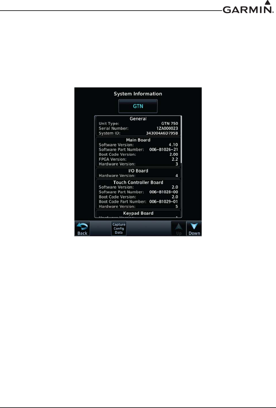
3.4.2 System Information
View the System Information page, as shown in Figure 3-10, by touching System Information key on the
Configuration Mode page. The System Information page displays the unit type, serial number, and system
ID for the GTN. It also contains the software and hardware versions of the Main, I/O, Display, Keypad,
LED, GPS/WAAS, COM and NAV boards. This information is also available for certain other LRUs
connected to the GTN. Touch the GTN key and choose which LRU to display. Touch UP or DOWN to
view all the information.
Figure 3-10. System Information Page
190-01007-A1 System Maintenance Manual GTN 6XX/7XX Part 23 AML STC
Rev. 7 Page 3-9
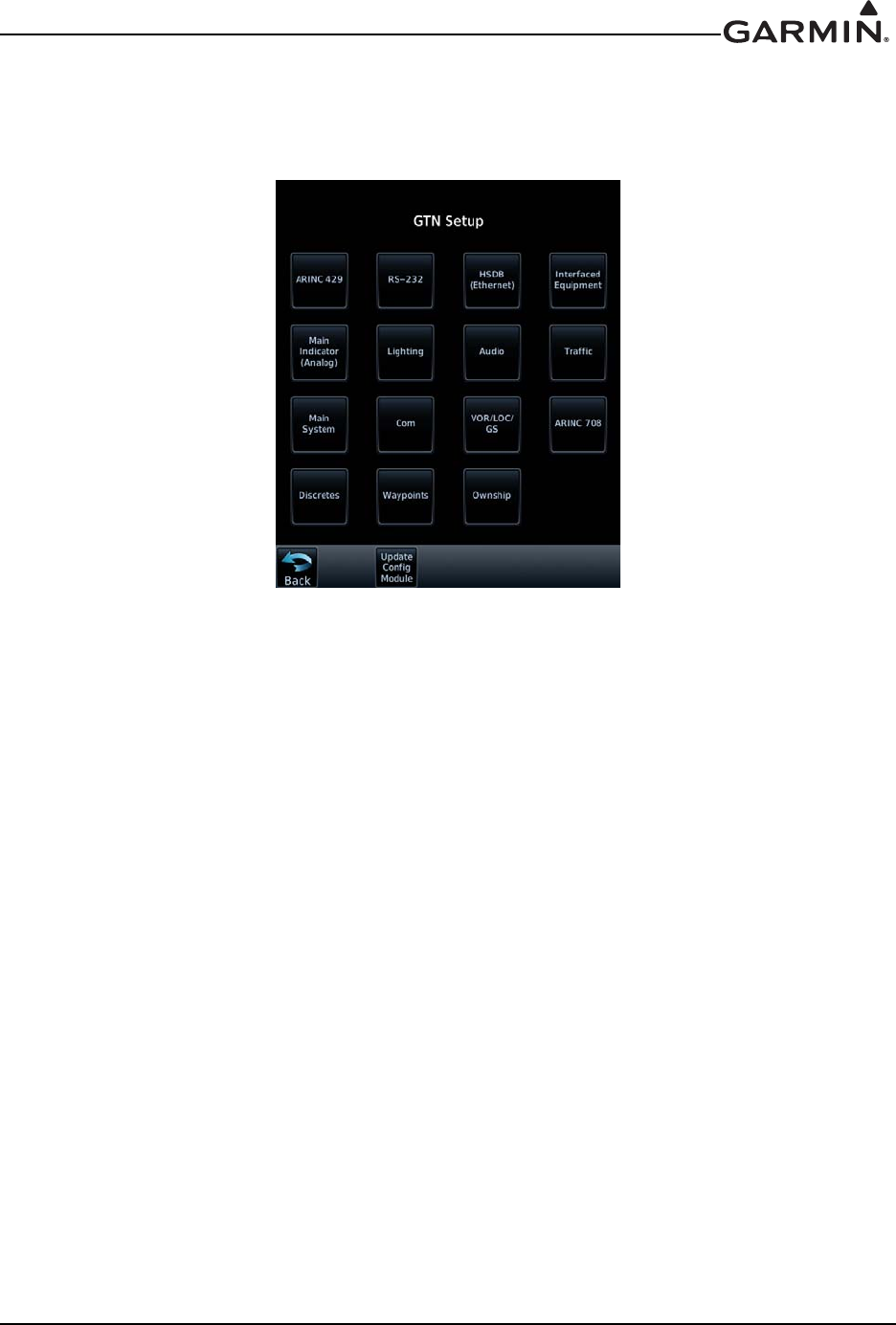
3.4.3 GTN Setup Page
This section provides a brief overview of the pages that are accessed from the GTN Setup page, as shown
in Figure 3-11, are described below. To access the GTN Setup page, touch the GTN Setup key from the
Configuration Mode page as shown in Figure 3-8.
Figure 3-11. GTN 7XX Setup Pages
ARINC 429
This page allows the user to configure the ARINC 429 input and output ports on the GTN. Both
ARINC 429 formats and bus speeds are set from this configuration page.
RS-232
This page allows the user to configure the RS-232 input and output ports on the GTN.
HSDB (Ethernet)
This page allows the user to set which Ethernet ports are connected.
Interfaced Equipment
This page allows the user to configure which LRUs are installed and interfaced to the GTN. The
transponder selection is automatically configured when a valid transponder configuration is selected under
the RS-232 page.
Main Indicator (Analog)
This page allows the user to calibrate the OBS resolver, and configure the CDI key, selected course for
GPS and VLOC as well as the V-Flag state.
Lighting
This page allows the user to set the display parameters that affect the backlight and key lighting brightness.
Enhanced Lighting
This page replaces the ‘Lighting’ page when enabled under the ‘Main System’ configuration page.
Enhanced lighting allows the user to set the display parameters that affect the backlight and key lighting
brightness. Enhanced lighting may be used to configure separate Day/Night lighting curves.

190-01007-A1 System Maintenance Manual GTN 6XX/7XX Part 23 AML STC
Rev. 7 Page 3-10
Audio
This page allows the user to configure the aural alert volume.
Traffic
This page allows the user to configure the traffic intruder symbol color and configure whether or not the
GTN is the display used to control the traffic system.
Main System
This page allows the user to display miscellaneous configuration options for the GTN. Air/Ground
Threshold, Air/Ground Discrete, Fuel Type, and Heading/Altitude input source connection statuses are
settings on this page.
COM
This page allows the user to configure the RF squelch volume, Mic 1 Gain, and sidetone volume. These
selections are only available for the GTN 635, 650, and 750 units.
VOR/LOC/GS
This page allows the user to check the CDI outputs from the VOR/LOC/GS receiver as well as the OBS
resolver input to the VOR receiver. It is also used to format the DME tuning data. This selection is only
available for the GTN 650 and 750 navigation units.
ARINC 708
This page allows the user to configure the GTN ARINC 708 input port. Selection of one of the approved
ARINC 708 weather radars is only possible if the digital radar enablement is active. This setting is only
available for the GTN 725 and 750 navigation units.
Discretes
This page allows the user to customize the configuration of discrete inputs/outputs on the J1001 and J1002
connectors.
Waypoints
These settings are not used in this STC.
Ownship
This page allows the user to select the displayed ownship icon from a list.
190-01007-A1 System Maintenance Manual GTN 6XX/7XX Part 23 AML STC
Rev. 7 Page 3-11
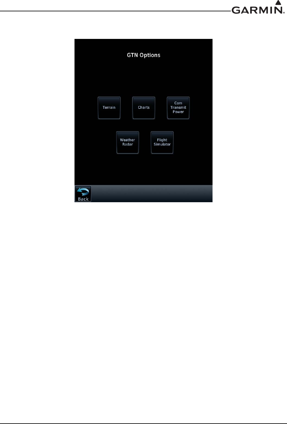
3.4.4 GTN Options Page
Figure 3-12. GTN 7XX Options Pages
190-01007-A1
Rev. 7
System Maintenance Manual GTN 6XX/7XX Part 23 AML STC
Page 3-12
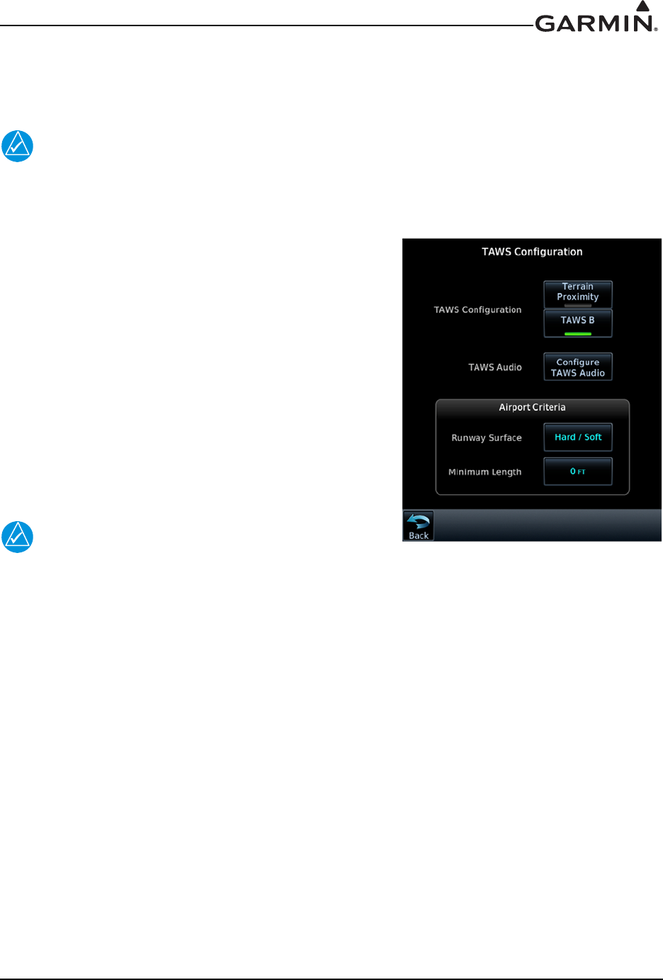
3.4.4.1 TAWS-B Enablement
When the optional TAWS feature is enabled, the GTN will provide Class B TAWS functionality. This
section describes how to reactivate the TAWS feature in the GTN.
NOTE
For first time TAWS enablement, refer to the GTN 6XX/7XX AML STC IM, P/N 190-01007-A3,
for additional requirements and checkout procedures. This manual only describes the
necessary steps to re-enable the feature for existing installations.
1. Turn the GTN off by pulling the NAV/GPS circuit
breaker.
2. Remove the database SD card from the data card slot
and insert the TAWS Enablement Card,
P/N 010-00878-01, which was used at the initial
installation.
3. Enter configuration mode by applying power (closing
the circuit breaker) to the GTN while holding the
HOME key.
4. Go to the Terrain Configuration page from the GTN
Options page. Touch the TAWS B key.
When the TAWS feature is activated, the TAWS B key will be
lit green, as shown in Figure 3-13.
NOTE
The feature enablement card should be provided to the
customer after service has been completed.
3.4.4.1.1 TAWS-B Configuration Options
When TAWS-B is enabled as shown in Figure 3-13, the following configuration settings may be accessed:
TAWS Audio
This configuration setting allows the user to select aural alert messages for various caution and warning
types.
Airport Criteria
The GTN TAWS alerting algorithm adapts the terrain alerting criteria based on nearby airports. The
Airport Criteria configuration options allow the user to select the minimum criteria that the airport must
meet to be considered as a nearby airport for the purpose of TAWS alerting. See Section 7.5.1 for more
details.
Figure 3-13. GTN 7XX TAWS
Configuration Page
190-01007-A1 System Maintenance Manual GTN 6XX/7XX Part 23 AML STC
Rev. 7 Page 3-13
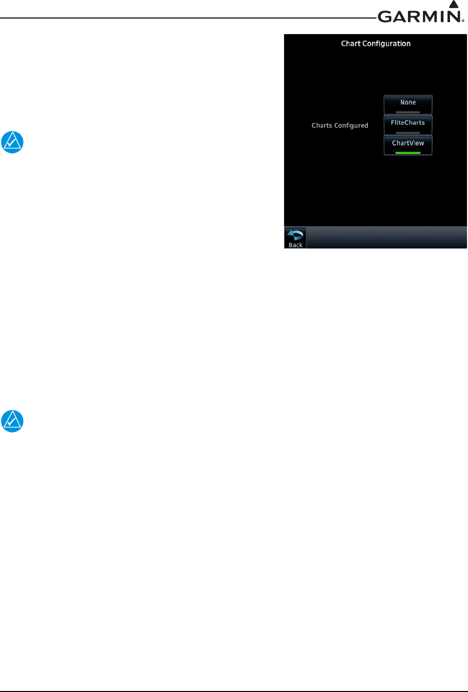
3.4.4.2 ChartView™ Enablement (GTN 7XX Only)
The GTN 7XX can display Jeppesen charts using the optional
ChartView feature, which must be activated. To configure
which Charts to display, touch either None, FliteCharts, or
ChartView. If ChartView is selected, it must be enabled as
described below.
NOTE
For first time Chartview enablement, refer to the GTN
6XX/7XX AML STC IM, P/N 190-01007-A3, for
additional requirements and checkout procedures. This
manual only describes the necessary steps to re-enable
the feature for existing installations.
1. Turn the GTN off by pulling the NAV/GPS circuit
breaker.
2. Remove the database SD card from the data card slot
and insert the ChartView Enablement Card,
P/N 010-00878-04, which was used at the initial installation.
3. Enter configuration mode on the GTN by applying power to the GTN (closing the circuit breaker)
while holding the HOME key.
4. Go to the Charts page from the GTN Options page. Touch the ChartView key.
5. When the ChartView feature is activated, the ChartView key will be lit green, as shown in
Figure 3-14.
NOTE
The feature enablement card should be provided to the customer after service has been
completed.
Figure 3-14. Chart Configuration
Page
190-01007-A1 System Maintenance Manual GTN 6XX/7XX Part 23 AML STC
Rev. 7 Page 3-14
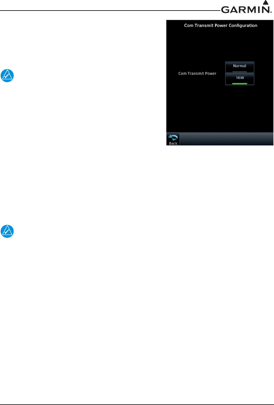
3.4.4.3 COM Transmit Power Enablement
When the optional 16W COM power is configured, the GTN
COM will transmit with 16 watts rather than the standard 10
watts. This section describes how to re-enable the 16W COM
transmit power.
NOTE
For first time COM transmit enablement, refer to the
GTN 6XX/7XX AML STC IM, P/N 190-01007-A3, for
additional requirements and checkout procedures. This
manual only describes the necessary steps to re-enable
the feature for existing installations.
1. Turn the GTN off by pulling the NAV/GPS circuit
breaker.
2. Remove the database SD card from the data card slot
and insert the 16W Enablement Card,
P/N 010-00878-04, that was used at the initial installation.
3. Enter configuration mode by applying power to the GTN (closing the circuit breaker) while
holding the HOME key.
4. Go to the COM Transmit Power page from the GTN Options page. Touch the 16W key.
5. When the 16W COM feature is activated, the 16W key will be lit green, as shown in Figure 3-15.
NOTE
The feature enablement card should be provided to the customer after service has been
completed.
Figure 3-15. COM Transmit
Power Configuration Page
190-01007-A1 System Maintenance Manual GTN 6XX/7XX Part 23 AML STC
Rev. 7 Page 3-15
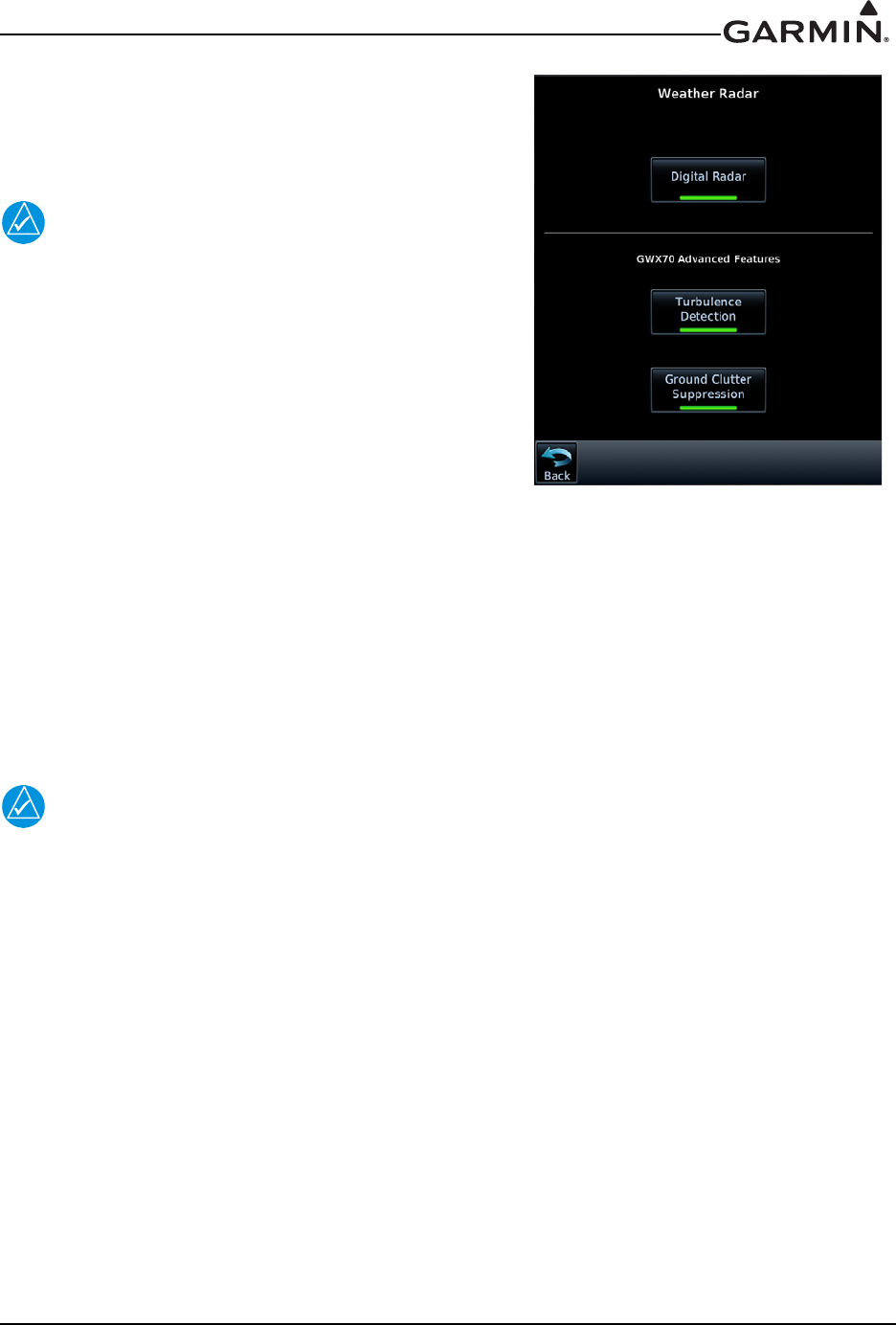
3.4.4.4 Digital Radar Enablement (GTN 7XX Only)
This section describes how to re-enable the Digital Radar
feature, which allows approved ARINC 708 Weather Radars
to be interfaced with the GTN 7XX.
NOTE
For first time Digital Radar enablement, refer to the
GTN 6XX/7XX AML STC IM, P/N 190-01007-A3,
for additional requirements and checkout
procedures. This manual only describes the
necessary steps to re-enable the feature for existing
installations.
1. Turn the GTN off by pulling the NAV/GPS circuit
breaker.
2. Remove the database SD card from the data card slot
and insert the Digital Radar Enablement Card,
(P/N 010-00878-42), that was used at the initial installation.
3. Enter configuration mode on the GTN by applying power to the GTN (closing the circuit breaker)
while holding the HOME key.
4. Go to the Weather Radar page from the GTN Options page. Touch the Digital Radar key, as
shown in Figure 3-16.
5. When prompted, touch Yes to enable Digital Weather Radars. When the feature is activated, the
Digital Radar key will be lit green.
NOTE
The feature enablement card should be provided to the customer after service has been
completed.
Figure 3-16. Weather Radar Page

190-01007-A1 System Maintenance Manual GTN 6XX/7XX Part 23 AML STC
Rev. 7 Page 3-16
3.4.4.5 GWX 70 Advanced Features (GTN 7XX Only)
The GTN 7XX can enable two Doppler radar features for the GWX 70. A Radar Turbulence Detection
Card (P/N 010-00878-45 or 010-00878-47 (dual install)) is needed for Turbulence Detection and a Radar
Automatic Ground Clutter Suppression Enablement Card (P/N 010-00878-44 or 010-00878-46 (dual
install)) is needed for Ground Clutter Suppression.
NOTE
For first time GWX 70 advanced feature enablement, refer to the GTN 6XX/7XX AML
STC IM, P/N 190-01007-A3, for additional installation requirements and checkout
procedures. This manual only describes the necessary steps to re-enable the feature for
existing installations.
To enable Radar Turbulence Detection:
1. Turn the GTN off by pulling the NAV/GPS circuit breaker.
2. Remove the database SD card from the data card slot and insert the Radar Turbulence Detection
Enablement Card (P/N 010-00878-45), that was used at the initial installation.
3. Enter configuration mode on the GTN by applying power to the GTN (closing the circuit breaker)
while holding the HOME key.
4. Go to the Weather Radar page from the GTN Options page. Touch the Turbulence Detection key,
as shown in Figure 3-16.
5. When prompted, touch Yes to enable Turbulence Detection. When the feature is activated, the
Turbulence Detection key will be lit green.
To enable Ground Clutter Suppression:
1. Turn the GTN off by pulling the NAV/GPS circuit breaker.
2. Remove the database SD card from the data card slot and insert the Radar AGCS Enablement Card
(P/N 010-00878-44) that was used at the initial installation.
3. Enter configuration mode on the GTN by applying power to the GTN (closing the circuit breaker)
while holding the HOME key.
4. Go to the Weather Radar page from the GTN Options page. Touch the Ground Clutter
Suppression key, as shown in Figure 3-16.
5. When prompted, touch Yes to enable Ground Clutter Suppression. When the feature is activated,
the Ground Clutter Suppression key will be lit green.
NOTE
The feature enablement card should be provided to the customer after service has been
completed.
190-01007-A1 System Maintenance Manual GTN 6XX/7XX Part 23 AML STC
Rev. 7 Page 3-17
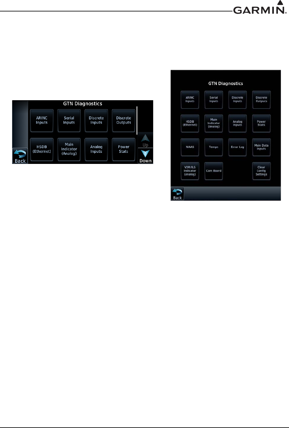
3.4.5 GTN Diagnostics Page
The GTN Diagnostics page, shown in Figure 3-17, is accessed from the Configuration Mode Home page
and is a useful tool for diagnosing issues and troubleshooting problems. Ground checks are also performed
using the tools on this page.
Figure 3-17. GTN 6XX and 7XX Diagnostics Pages
ARINC Inputs
This page displays the ARINC 429 data that is being received over each ARINC 429 port. Each port can be
chosen for display by touching the Port key and toggling between the input ports. Select a port to display.
The GTN will then display the label, SSM, Data, and SDI for each ARINC 429 input port. This is useful
for determining if the expected labels are being received and also for troubleshooting incorrect or swapped
wiring to the input ports. The data log can be paused by toggling the Pause key. Clear the data log by
touching Clear Log key.
Serial Inputs
This page displays the serial data that is being received and is useful for determining if the GTN is
receiving data on each connected port. Select the desired port by touching the Port key and selecting the
RS-232 channel from the list. The data log can be paused by toggling the Pause key. Clear the data log by
touching Clear Log.
Discrete Inputs
This page displays the state of each of the discrete input pins on the GTN. This page is useful for
troubleshooting discrete wiring issues.
Discrete Outputs
This page displays the state of each of the discrete outputs and allows them to be toggled between active
and inactive. This is useful for ensuring that annunciator and signal outputs are properly connected to
annunciator lights or other LRUs and that they are receiving the signal.

190-01007-A1 System Maintenance Manual GTN 6XX/7XX Part 23 AML STC
Rev. 7 Page 3-18
HSDB Ethernet
This page displays the status of each HSDB port to be displayed. This page displays whether or not each
port is receiving data and displays whether the port is connected or not connected. The communication
status of each installed HSDB LRU is also displayed.
Main Indicator (Analog)
This page displays the CDI connected to the main board (P1001) to be ground checked and allows the
interface to be verified.
Analog Inputs
This page displays the bus voltage setting for Lighting Bus 1 and Lighting Bus 2 as well is the input
voltage setting for each bus. It also displays synchro heading input diagnostics information such as heading
angle, heading valid status, AC voltage, and AC frequency.
Power Stats
This page displays the number of times the GTN has powered up as well as the total elapsed operating
hours for the GTN.
WAAS Diagnostics
This page displays the WAAS engine status, including UTC date/time, current Lat/Lon, overall navigation
status, oscillator temperature, and AGC voltage. This page also allows the GPS/WAAS engine to be reset.
Temps
This page displays the current, minimum, maximum, and average board temperatures for the LED Board,
Main Board, Display Interface Board, GPS/WAAS Board, and COM Board.
Error Log
This page allows the error log to be written to the SD card in the front slot. It also allows the error log to be
cleared.
Main Data Inputs
This page allows the data on ARINC 429, RS-232, and other electrical inputs to be monitored. This is used
for checking electrical interfaces during installation and troubleshooting. Information that is not being
received by the GTN is dashed out.
VOR/ILS Indicator (Analog)
This page allows the CDI connected to the NAV board (P1004) to be ground checked and allows the NAV
indicator interface to be verified.
COM Board Diagnostics Page
This page displays status of the FPGA flash, nonvolatile memory, synthesizer lock calibration, and
reversionary as well as the transmitter power limit.
Clear Config Settings
CAUTION
This key should only be pressed if the intent is to clear all configuration settings. Touching
the Clear Config Settings key opens a confirmation window to reset all of the settings
stored in the configuration module to their defaults.
190-01007-A1 System Maintenance Manual GTN 6XX/7XX Part 23 AML STC
Rev. 7 Page 3-19
3.5 Database Updates
The GTN utilizes various databases. The Navigation, Basemap, SafeTaxi, and Obstacle databases reside
internal to the GTN, while the Terrain and Charts databases are stored on the removable memory card
located in the vertical slot on the left side of the GTN. The following describes each database and how the
databases are updated. See Table 3-1 for a summary of the database location and update rate. The GTN
Database card, Garmin P/N 010-00900-00, includes the Basemap, Obstacle, SafeTaxi, and Navigation
databases.
CAUTION
The databases on the GTN Database Card are locked to specific GTN installations. The
first time the GTN Database Card is inserted into a GTN, it associates exclusively with
that particular GTN and will not work in other installations.
Table 3-1. GTN Database Summary
Database Update Rate Stored Location
Terrain Database Periodic (When available) Data Card
FliteCharts Database 28 Days Data Card
ChartView Database 14 Days Data Card
Obstacle Database with Hotlines 56 Days Internal
SafeTaxi Database 56 Days Internal
Basemap Database Periodic (When available) Internal
Navigation Database 28 Days Internal

190-01007-A1 System Maintenance Manual GTN 6XX/7XX Part 23 AML STC
Rev. 7 Page 4-2
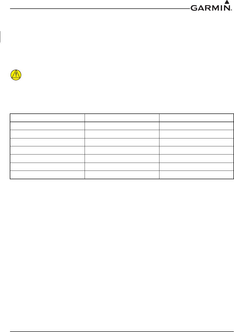
4.3 Maintenance Intervals
Table 4-1. Periodic Maintenance
Item Description/Procedure Interval
Equipment Removal
and Replacement
Removal and replacement of the following items. See Section 6
of this document for instructions.
•GTN 6XX/7XX, Flight Stream 210, or GMA 35 units
• NAV antenna cable splitter
• NAV antenna cable diplexer
•Fan
On Condition
Cleaning the Front
Panel
The front bezel, keypad, and display can be cleaned with a soft
cotton cloth dampened with clean water. DO NOT use any
chemical-cleaning agents. Care should be taken to avoid
scratching the surface of the display.
On Condition
Display Backlight
The display backlight LEDs are rated by the manufacturer as
having a usable life of at least 36,000 hours. This life may be
more or less than the rated time depending on the operating
conditions of the GTN. Over time, the backlight lamp may dim
and the display may not perform as well in direct sunlight
conditions. The user must determine by observation when the
display brightness is not suitable for its intended use. Contact the
Garmin factory repair station when the backlight lamp requires
service.
On Condition
Battery
Replacement
The GTN has an internal keep-alive battery that will last about 10
years. The battery is used for GPS system information. Regular
planned replacement is not necessary. The GTN will display a
‘low battery’ message when replacement is required. Once the
low battery message is displayed, the battery should be replaced
within 1 to 2 months.
If the battery is not replaced and becomes totally discharged, the
GTN unit will remain fully operational, but the GPS signal
acquisition time may be increased. There is no loss of function or
accuracy of the GTN unit with a dead battery.
The battery must be replaced by the Garmin factory repair
station or factory authorized repair station.
On Condition
Test - Bonding
Check
Perform an electrical bonding check of the GTN, GMA 35
(if installed), and Flight Stream 210 (if installed) per Section 4.5.
Every 10
years or 2000
flight hours,
whichever
comes first.
Test TVS Lightning
Protection
The GTN #1 main power input will have a TVS located at the
LRU, for IFR non-metallic aircraft only. The TVS must be
checked or replaced in accordance with Section 4.6.1.
24 Calendar
Months
190-01007-A1 System Maintenance Manual GTN 6XX/7XX Part 23 AML STC
Rev. 7 Page 4-3
4.4 Visual Inspection
Conduct a visual check of the GTN unit, switches, GMA 35 (if installed), and their wiring harnesses to
ensure continued installation integrity.
1. Inspect the GTN unit(s), GMA 35, and Flight Stream 210 for security of attachment, including
visual inspection of mounting racks and other supporting structure attaching the racks to aircraft
instrument panel.
CAUTION
Care should be taken when tightening the mounting screws of the Flight Stream 210.
Excessive tightening may damage the mounting flange.
2. Inspect for signs of corrosion.
3. Inspect all switches, knobs, and buttons for damage.
4. Inspect condition of wiring, shield terminations, routing, and attachment/clamping.
5. Check the fan intake slots on the sides and bottom of the GTN unit’s bezel for dust, dirt, or
obstructions. Clean as needed.
6. Conduct a visual check of the GPS/SBAS antenna cable overbraid if installed.
7. Conduct a visual check of the WXR cable overbraid if installed.
8. Conduct a visual check of any bonding strap or conductive tape used for electrical bonding or RF
ground plane (if installed). Replace any damaged or torn strap. See Section 6.12 or Section 6.13
for details. Replace any torn bonding tape using a heavy duty aluminum foil tape such as
3M P/N 438 or other foil with aluminum that is 7.2 mils thick or greater. If strap termination
hardware is loose, tighten and retest bonding, see Section 4.5 for details.
Test Lightning
Protection
The GTN #1 main power input and NAV power input will have a
TVS located at the LRU, for IFR non-metallic aircraft only. The
TVS must be replaced in accordance with Section 4.6.1.
Conduct a visual check of the GPS/SBAS antenna cable
overbraid in accordance with Section 4.7
Conduct a visual check of the WXR cable overbraid in
accordance with Section 4.8 if installed.
After a
suspected or
actual
lightning
strike
Visual Inspection
The GTN unit, GMA 35 (if installed), Flight Stream 210
(if installed), switches, and wiring harnesses should be inspected
to ensure continued integrity of the installation. These items must
be inspected in accordance with Section 4.4.
12 Calendar
Months
Item Description/Procedure Interval
GTN 6XX/7XX - Verify the countersunk fastener heads are in full contact with the unit
mounting rack holes. Re-torque the mounting screws 12-15 in-lbs if required.
GMT 35 - If the GMA 35 is installed, verify the countersunk fastener heads are in full contact
with the unit mounting rack holes. Re-torque the GMA 35 mounting screws to 8.5-9.5 in-lbs if
required.
Flight Stream 210 - If the Flight Stream 210 is installed and screws are not securely attached,
tighten any loose Flight Stream 210 mounting screws as necessary to snug plus one-quarter
turn. If required, re-torque bonding strap hardware to 12-15 in-lbs.

190-01007-A1 System Maintenance Manual GTN 6XX/7XX Part 23 AML STC
Rev. 7 Page 4-4
4.5 Electrical Bonding Test
4.5.1 GTN Bonding Check (Metallic or Tube/Fabric Aircraft)
Perform an electrical bonding check as follows:
1. Remove the GTN 6XX or GTN 7XX from the mounting rack.
2. Remove the backplate assembly from the rack.
NOTE
For GTN 7XX only, if the GMA 35 is installed, it must be removed from its rack and the
GMA 35 backplate assembly must be removed prior to performing Step 3. When a
GMA 35 bonding check is planned, perform the GMA 35 bonding check prior to
reinstalling the GTN backplate assembly to the rack.
3. Measure the resistance between the mounting rack and nearby exposed portion of aircraft metallic
structure and verify it is less than or equal to 10 milliohms.
NOTE
A bonding test failure may occur if a fastener is not secured to the specified torque value.
For installations that use screws in lieu of rivets to secure the rack to surrounding
structure, verify that the screws are torqued to the appropriate value before proceeding to
remove the rack. See Section 4.4 for torque values.
In the event of bonding test failure, remove the GTN rack and clean the attachment points with a bonding
brush at both the GTN rack and the aircraft and reattach the rack to the rails in the panel. Re-verify the
resistance between the mounting rack and nearby exposed portion of aircraft metallic structure and ensure
that the resistance is less than or equal to 2.5 milliohms.
4. Reinstall the backplate assembly and reinstall the GTN in the mounting rack.

190-01007-A1 System Maintenance Manual GTN 6XX/7XX Part 23 AML STC
Rev. 7 Page 4-5
4.5.2 GTN (Composite Aircraft)
Perform an electrical bonding check as follows:
1. Remove the GTN 6XX or GTN 7XX from the mounting rack.
2. Remove the backplate assembly from the rack.
NOTE
For GTN 7XX only, if the GMA 35 is installed, it must be removed from its rack and the
GMA 35 backplate assembly must be removed prior to performing Step 3.
3. Measure the resistance between the mounting rack and the instrument panel, verify it is less than
or equal to 10 milliohms.
NOTE
A bonding test failure may occur if a fastener is not secured to the specified torque value.
For installations that use screws in lieu of rivets to secure the rack to surrounding
structure, verify that the screws are torqued to the appropriate value before proceeding to
remove the rack. See Section 4.4 for torque values.
In the event of bonding test failure, remove the GTN rack and clean the attachment points with a bonding
brush at both the GTN rack and the aircraft and reattach the rack to the rails in the panel. Re-verify the
resistance between the mounting rack and the instrument panel and ensure that the resistance is less than or
equal to 5 milliohms.
4. Reinstall the backplate assembly and reinstall the GTN in the mounting rack.

190-01007-A1 System Maintenance Manual GTN 6XX/7XX Part 23 AML STC
Rev. 7 Page 4-6
4.5.3 GMA 35 (Metallic or Tube/Fabric Aircraft)
A bonding check is required for the GMA 35. Perform an electrical bonding check as follows:
1. Gain access to the GMA 35 by removing the GTN 7XX.
2. Remove the GMA unit from the mounting rack.
3. Remove backplate assembly from the rack.
NOTE
The GTN 7XX backplate assembly must be removed from the GTN rack prior to
performing Step 4.
4. Measure the resistance between the mounting rack and nearby exposed portion of aircraft metallic
structure and verify it is less than or equal to 10 milliohms.
NOTE
A bonding test failure may occur if a fastener is not secured to the specified torque value.
For installations that use screws in lieu of rivets to secure the rack to surrounding
structure, verify that the screws are torqued to the appropriate value before proceeding to
remove the rack. See Section 4.4 for torque values.
In the event of bonding test failure, remove the GMA 35 rack and clean the attachment points with a
bonding brush at both the GMA rack and the aircraft attachment points. Re-verify the resistance between
the mounting rack and nearby exposed portion of aircraft metallic structure and ensure that the resistance is
less than or equal to 2.5 milliohms.
5. Reinstall the backplate assembly and reinstall the GMA unit in the mounting rack.
4.5.4 GMA 35 (Composite Aircraft)
1. Gain access to the GMA 35 by removing the GTN 7XX.
2. Remove the GMA unit from the mounting rack.
3. Remove the backplate assembly from the rack.
NOTE
The GTN 7XX backplate assembly must be removed from the GTN rack prior to
performing Step 4.
4. Measure the resistance between the mounting rack and the instrument panel, and verify it is less
than or equal to 10 milliohms.

190-01007-A1 System Maintenance Manual GTN 6XX/7XX Part 23 AML STC
Rev. 7 Page 4-7
NOTE
A bonding test failure may occur if a fastener is not secured to the specified torque value.
For installations that use screws in lieu of rivets to secure the rack to surrounding
structure, verify that the screws are torqued to the appropriate value before proceeding to
remove the rack. See Section 4.4 for torque values.
In the event of bonding test failure, remove the GMA 35 rack and clean the attachment points with a
bonding brush at both the GMA rack and the aircraft attachment points. Re-verify the resistance between
the mounting rack and the instrument panel and ensure that the resistance is less than or equal to 5
milliohms.
5. Reinstall the backplate assembly and reinstall the GMA unit in the mounting rack.
4.5.5 Flight Stream 210 (Metallic or Tube/Fabric Aircraft)
1. Disconnect the shield terminations from the Flight Stream connector backshell.
2. Measure the resistance between the connector and nearby exposed portion of aircraft metallic
structure and check that it is less than or equal to 20 milliohms.
In the event of bonding test failure, remove the Flight Stream connector bonding strap from the aircraft
ground plane and clean the attachment point with a bonding brush. Re-attach the bonding strap to the
aircraft ground plane, torque to 12-15 in-lbs. Re-check the resistance between the Flight Stream
connector and aircraft structure, ensuring that the resistance is less than or equal to 10 milliohms. If
cleaning the far side of the strap is not enough, remove, clean, and reattach on the Flight Stream 210 side.
3. Connect the shield terminations to the Flight Stream connector backshell.
4.5.6 Flight Stream 210 (Composite Aircraft)
1. Disconnect the shield terminations from the Flight Stream connector backshell.
2. Measure the resistance between the connector and instrument panel (or other aircraft ground) and
check that it is less than or equal to 20 milliohms.
In the event of bonding test failure, remove the Flight Stream connector bonding strap from the aircraft
ground plane and clean the attachment point with a bonding brush. Re-attach the bonding strap to the
aircraft ground plane, torque to 12-15 in-lbs. Re-check the resistance between the Flight Stream
connector and aircraft ground, ensuring that the resistance is less than or equal to 10 milliohms. If
cleaning the far side of the strap is not enough, remove, clean, and reattach on the Flight Stream 210 side.
3. Connect the shield terminations to the Flight Stream connector backshell.

190-01007-A1 System Maintenance Manual GTN 6XX/7XX Part 23 AML STC
Rev. 7 Page 4-8
4.6 Transient Voltage Suppressor (TVS) (If Installed)
After a suspected lightning strike, each TVS and TVS assembly (if installed) must be replaced. Refer to
Section 6.9.1 for information on installing in-line TVSs.
4.6.1 GTN TVS1 Check (GTN #1 Only)
NOTE
The GTN should be the only LRU connected to the NAV/GPS circuit breaker. If other
equipment is connected to the NAV/GPS circuit breaker it must also be disconnected prior
to conducting the following check. No other TVS devices should be on this circuit. If the
TVS being checked is not isolated, erroneous readings may result.
For a dual GTN installation, only GTN #1 will have the TVS protection. The following checks will only
apply to GTN #1. Reference the appropriate GTN power interconnect drawings. To check the TVS on the
GTN power inputs, the following steps should be followed:
1. Remove the GTN as described in Section 6.1.
2. Open the GTN’s circuit breaker and use a multi-meter to perform a diode check between P1001-19
and ground:
a.The meter should indicate open with the red lead on P1001-19 and the black lead on ground.
b.The meter should indicate a diode drop of between 2.0V and 2.5V with the red lead on
ground and the black lead on P1001-19.
i)If the diode drop is outside of the above range, replace the TVS.
ii)If the meter indicates a short during steps 2a or 2b, replace the TVS.
iii)If the meter indicates an open in both directions, check the continuity of the fuse.
iv)If the fuse is open, replace the fuse and repeat the check.
v)If the fuse is good, check the wiring for faults. If the wiring is good, replace the TVS.
3. Verify continuity between P1001-19 and P1001-20.
4. Reinstall the GTN as described in Section 6.1 and reset the GTN’s circuit breaker.
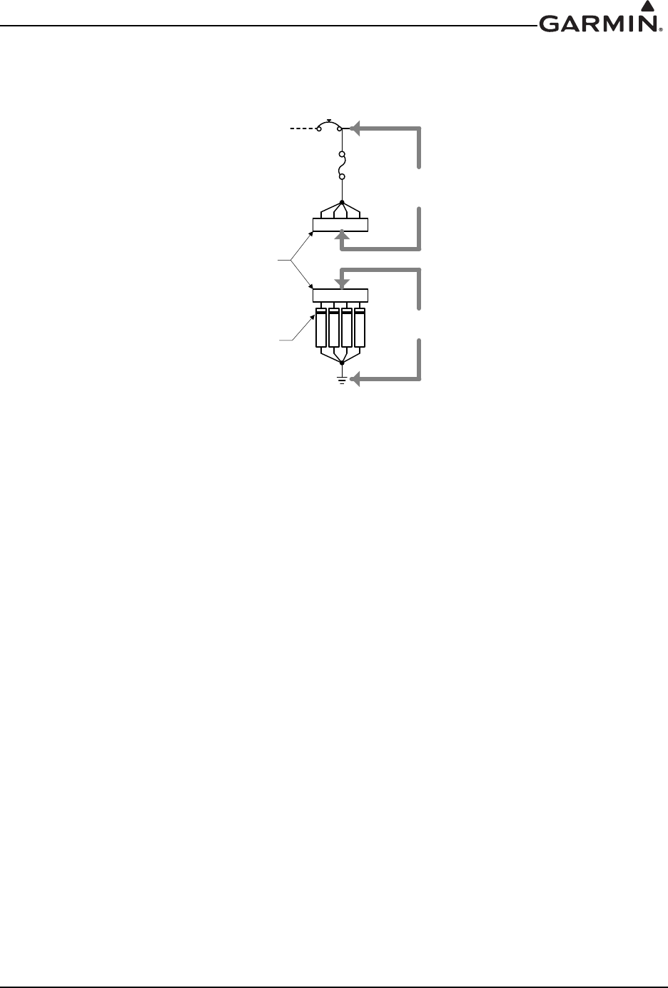
190-01007-A1 System Maintenance Manual GTN 6XX/7XX Part 23 AML STC
Rev. 7 Page 4-9
4.6.2 GTN TVS2 Assembly Check (GTN #1 Only)
The TVS assembly (refer to Section 6.9) and fuse on the power bus side of GTN #1 must be inspected.
Verify operation of all four TVSs prior to replacing any failed TVS.
Figure 4-1. TVS Assembly Check
Check the TVS assembly (TVS2) as follows:
1. Ensure that the power to the bus is off and disconnect the connector in the TVS assembly.
2. Use a multi-meter to perform a diode check between the first connector contact (socket contact on
the first TVS) and ground. Refer to Figure 4-1.
3. The meter should indicate open with the red lead on the connector socket contact and the black
lead on ground:
a) The meter should indicate a diode drop of between 2.0V and 2.5V with the red lead on
ground and the black lead on the connector socket contact.
i. If the diode drop is outside of the above range, replace the TVS diode corresponding
to the contact being checked.
ii. If the meter indicates a short, replace the TVS diode corresponding to the contact
being checked.
iii. If the meter indicates an open, check the wiring for faults. If the wiring is good,
replace the TVS diode corresponding to the contact being checked.
4. Repeat checks in the previous step for each of the three remaining contacts/TVS diodes.
5. On the other connector, verify continuity between each of the four contacts and the power bus.
a) If there is no continuity between the power bus and all four contacts, check the continuity of
the fuse.
b) If there is continuity between the power bus and some contacts but not others, check the wir-
ing to the ‘open’ contacts and repair as necessary.
6. Reconnect the connector in the TVS assembly.
$
796',2'(&+(&.
675,3(21
796,1',&$7(6
&$7+2'(6,'(
72*71
7
9
6
7
9
6
7
9
6
7
9
6
796$66(0%/<
&211(&725
&217,18,7<&+(&.

190-01007-A1 System Maintenance Manual GTN 6XX/7XX Part 23 AML STC
Rev. 7 Page 4-10
4.7 GPS/SBAS Antenna Cable Overbraid Inspection (If Installed)
The GPS/SBAS antenna cable overbraid must be inspected after a known or suspected lightning strike.
Check the antenna and overbraid for the following:
1. Check the cable overbraid for pinching, melting or evidence of arcing at the GPS/SBAS antenna
end and at the GTN 6XX/7XX.
2. Check the lug at the GTN end for evidence of arcing and verify that the lug is still secured to the
overbraid and to the GTN connector shield block.
3. Check that the overbraid is securely attached at the GPS/SBAS antenna end and at the
GTN6XX/7XX.
If any of these checks shows evidence of a lightning strike, replace the overbraid assembly in accordance
with Section 6.10.
4.8 WXR HSDB Cable Overbraid Inspection (If Installed)
The WXR HSDB cable overbraid must be inspected after a known or suspected lightning strike. Check the
overbraid for the following:
1. Check the cable overbraid for pinching, melting or evidence of arcing at the WXR end and at the
bulkhead to which the WXR R/T is mounted.
2. Check the lug at the WXR end for evidence of arcing and verify that the lug is still secured to the
overbraid and to the WXR shield block.
3. Check that the overbraid is securely attached at the bulkhead end.
If any of these checks shows evidence of a lightning strike, replace the overbraid assembly in accordance
with Section 6.11.

190-01007-A1 System Maintenance Manual GTN 6XX/7XX Part 23 AML STC
Rev. 7 Page 5-1
5 TROUBLESHOOTING
5.1 GTN General Troubleshooting
This section provides information to assist troubleshooting if problems occur after completing the
maintenance. Refer to the GTN System Configuration Log retained in the aircraft permanent records for a
list of the interfaced equipment and system configuration data. When troubleshooting the GTN or GMA
system, refer to the wire routing drawings and interconnect wiring diagrams that are retained in the aircraft
permanent records.
Table 5-1. GTN Troubleshooting Guide
Problem Possible Cause Corrective Action
The GTN does not
power on.
The unit is not getting power to the
main connector P1001.
Ensure power is connected to the main
78-pin connector P1001, pins 19 and 20
and ground to P1001, pins 77 and 78.
Check circuit breakers and main
avionics switch.
The GTN does not
compute a position.
Not receiving adequate GPS
signals.
Check the GPS antenna connections.
Make sure the aircraft is clear of
hangars, buildings, trees, etc.
Wait 20 minutes for GTN to download
full GPS almanac and acquire position.
GPS signal levels
drop when avionics
are turned on.
Noise interference from other
avionics.
Turn all avionics off, then turn on each
piece one at a time to isolate the source
of the interference. Route GPS cable
and locate GPS antenna away from
sources of interference.
The GPS signal
levels are very low.
Improper antenna installation or
coaxial routing.
Check GPS antenna installation,
connections, and cable routing. The
GPS antenna must be mounted on the
top of the aircraft.
Antenna shaded from satellites. Make sure the aircraft is clear of
hangars, buildings, trees, etc.
RF interference at 1575.42 MHz
from VHF COM.
Add a 1575.42 MHz notch filter in COM
coaxial. Fix or replace the COM.
Disconnect the ELT antenna coaxial to
check for possible re-radiation. Move
GPS antenna further from the COM
antenna.

190-01007-A1 System Maintenance Manual GTN 6XX/7XX Part 23 AML STC
Rev. 7 Page 5-2
The GTN COM does
not transmit.
The PTT input is not being pulled
low.
Check that the MIC 1 Transmit (P1003-
11) input is pulled low for transmit. The
state of this discrete input can be
monitored on the Discrete Inputs page
found on the GTN Diagnostics page.
See Section 3.4.5.
No transmit power to COM.
Make sure power input is connected to
the COM 44-pin connector P1003-30,
-43 and -44 and ground to P1003-37,
-38, and -40.
The input voltage is too low. Increase input supply voltage to
>11VDC.
The side tone level is
too low or too high.
Wrong type of headsets or side
tone level needs adjustment.
If necessary, adjust the side tone level.
Side tone adjustment is found on the
COM Setup Config Mode page.
OBS Resolver won’t
calibrate.
Incompatible resolver or improper
connection.
Check the resolver specifications and
wiring.
OBS indication on
GTN does not agree
with OBS setting.
GTN resolver input not calibrated
correctly. Check wiring and calibration.
Resolver has not been calibrated.
GTN TAWS Audio
not heard.
TAWS audio volume level set too
low. Increase TAWS audio volume level.
Check wiring.
Check audio panel volume and
audio wiring.
Main software version has just
been updated.
Allow up to 5 minutes for the TAWS
audio clips to load. Cycle power on the
GTN and verify that TAWS audio is
working properly.
GTN is not receiving
heading from
compass system
(ARINC 429 heading
input used).
ARINC 429 input port speed not
correct.
Check ARINC 429 input port speed
setting for port that device is connected
to and verify that the speed is correct for
that device.
Wiring connections are incorrect.
The raw data being received by the GTN
can be monitored on the ARINC Inputs
page found on the GTN Diagnostics
page. See Section 3.4.5.
Check wiring.
Problem Possible Cause Corrective Action

190-01007-A1 System Maintenance Manual GTN 6XX/7XX Part 23 AML STC
Rev. 7 Page 5-3
Autopilot is not
getting GPSS/Roll
Steering data from
the GTN (ARINC 429
Roll Steering used).
GTN does not have a position or
flight plan entered.
Acquire GPS position and enter a flight
plan.
GTN ARINC 429 output not
configured correctly.
Check ARINC 429 output port setting for
port to which autopilot is connected.
ARINC 429 output port speed not
correct.
Check ARINC 429 output port speed
setting for port that autopilot is
connected to and verify that the speed is
correct for autopilot.
Wiring connections are incorrect. Check wiring.
Certain autopilots require
groundspeed for GPSS to be
enabled.
Ensure that groundspeed is provided if
required by the autopilot. This can be
accomplished using GTN Demo Mode.
Tuning data not
updating DME.
Incorrect configuration. Check the DME Channel Mode on the
VOR/LOC/GS CDI page.
Wiring connections are incorrect.
Check wiring.
Output not configured correctly.
ARINC 429 device is
not receiving data
from the GTN.
GTN ARINC 429 output not
configured correctly.
Check ARINC 429 output port setting for
port that device is connected to.
Receiving LRU ARINC 429 input
port speed not correct.
Check ARINC 429 input port speed
setting for port that device is connected
to and verify that the speed is correct for
that device.
Wiring connections are incorrect. Check wiring.
RS-232 device is not
communicating with
the GTN.
GTN RS-232 port not configured
correctly.
Check RS-232 port setting for port that
device is connected to.
Improper setup on the remote
device.
Verify the configuration of the other
device.
Device not compatible, or improper
connection.
Verify GTN RX is connected to remote
device TX and GTN TX is connected to
remote device RX.
Multiple TX lines connected
together.
Verify that there is only one TX source
per RX port.
Wiring connections are incorrect. Check wiring.
Baud rate and parity settings not
set correctly.
Ensure the correct baud rate and parity
settings are selected in Config Mode.
CDI scaling on EFS
40/50 is not correct.
On EFS 40/50, (prior to SG465
software version 1501) FMS #1/#2
configuration is not set to
“KLN 90-GPS”.
Reconfigure EFS 40/50 for ‘KLN 90-
GPS’ on FMS #1/#2 inputs as
appropriate.
Problem Possible Cause Corrective Action

190-01007-A1 System Maintenance Manual GTN 6XX/7XX Part 23 AML STC
Rev. 7 Page 5-4
GTN boots into
configuration mode
rather than normal
mode.
Software Loader Card is inserted
into SD card slot.
Remove Software Loader Card and
insert database card. Ensure GTN
powers up in normal mode after this.
Reload software into the GTN (See
Section 3.3). Ensure the GTN powers up
in normal mode after this.
Problem Possible Cause Corrective Action
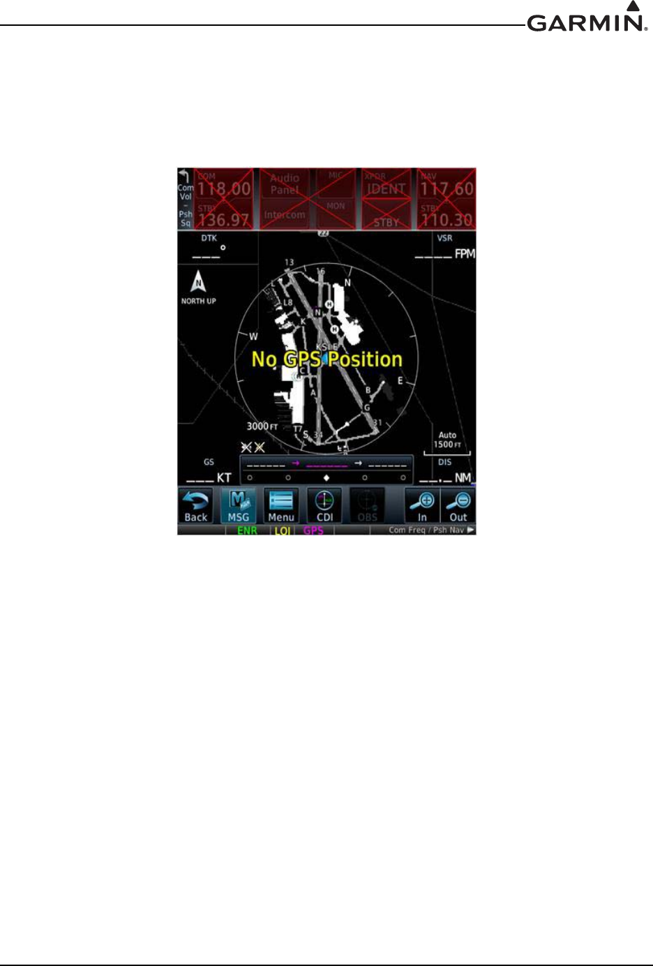

190-01007-A1 System Maintenance Manual GTN 6XX/7XX Part 23 AML STC
Rev. 7 Page 5-6
5.3 GTN System Messages
5.3.1 GTN System Related Alerts
Table 5-2. Alert Text Troubleshooting Guide
Alert Text Possible Cause Corrective Action
CROSSFILL
ERROR - Crossfill is
inoperative. See
CRG for crossfilled
items.
An error was detected during
unit-to-unit communication of
data. This can be caused by
problems with HSDB wiring or
by either GTN needing service.
See the Cockpit Reference
Guide (CRG) for crossfilled
items.
Start both GTNs in Configuration Mode
and ensure that both GTNs are
configured for crossfill.
Check J1002 connection on crossfilled
GTN units.
Ensure that P1002-10 of GTN #2 is
connected to ground.
DEMO MODE -
Demo mode is
active. Do not use
for navigation.
The GTN is in Demo Mode and
must not be used for actual
navigation.
Check that the DEMO MODE SELECT*
input (P1002-1) is not tied to ground. Also
ensure that the Direct-To key is not
stuck.
CDI/HSI FLAG -
Main lateral/vertical
flag on CDI/HSI is
inoperative.
The main lateral or vertical
superflag has been turned off
due to an overcurrent condition.
Check the GTN main lateral and vertical
superflag connections to the CDI/HSI for
correct wiring, shorts to ground, and
overcurrent. Superflags should not drive
more than 320 mA.
GTN - GTN needs
service.
The GTN has detected an
internal failure. Contact Garmin Technical Support.
COOLING - GTN
overtemp. Reducing
backlight
brightness.
The GTN has detected
excessive display backlight
temperature. The backlight has
been automatically dimmed to
reduce the unit temperature.
Check for adequate ventilation or check
cooling airflow. Also ensure the cooling
fan is operating and is unobstructed.
KEY STUCK -
HOME key is stuck.
The bezel’s Home key is stuck
in the enabled or pressed state.
Press the Home key again to cycle its
operation. If the message persists,
contact Garmin technical support.
KEY STUCK -
Direct-to key is
stuck.
The bezel’s Direct-To key is
stuck in the enabled or pressed
state.
Touch the Direct-To key again to cycle its
operation. If the message persists,
contact Garmin technical support.
KNOB STUCK -
Dual concentric
inner knob is stuck
in the pressed
position.
The inner large knob push-key
is stuck in the enabled or
pressed state. Knob is located
on the right side of the unit.
Press the knob to cycle its operation. If
the message persists, contact Garmin
technical support.
KNOB STUCK -
Volume knob is
stuck in the pressed
position.
The small knob push-key is
stuck in the enabled or pressed
state. Knob is located on the left
side of the unit.
Press the knob to cycle its operation. If
the message persists, contact Garmin
technical support.

190-01007-A1 System Maintenance Manual GTN 6XX/7XX Part 23 AML STC
Rev. 7 Page 5-7
CROSSFILL
ERROR - GTN
software mismatch.
See CRG for
crossfilled items.
The software does not match
between GTNs. Crossfill
disabled. See the Cockpit
Reference Guide (CRG) for
crossfilled items.
Check the software version of both GTNs
and ensure they match. Update the
software if needed.
CROSSFILL
ERROR - GTN
Navigation DB
mismatch. See CRG
for crossfilled items.
GTN #1 and GTN #2 have
different cycles of the
navigation database.
If it is desired to utilize the crossfill
function, load the most current cycles of
the navigation database to each GTN.
CONFIGURATION
MODULE - GTN
configuration
module needs
service.
The GTN configuration module
has failed. Verify the configuration module wiring is
correct.
Replace the configuration module.
The GTN configuration module
is incorrectly wired.
DATACARD
ERROR - Datacard
is invalid or failed.
The datacard is not being
properly read by the GTN.
Load the terrain database and any
Charts databases to a new datacard.
Replace the failed datacard.
REMOTE KEY
STUCK - Remote
OBS key is stuck.
The remote OBS switch is stuck
in the enabled or pressed state.
Press the switch again to cycle its
operation.
Go to the GTN DIAGNOSTICS -
DISCRETE INPUTS page in
configuration mode and check that the
state of the input changes when the OBS
switch is pressed and released.
Verify that the remote OBS switch wiring
is correct.
Contact Garmin technical support.
REMOTE KEY
STUCK - Remote
CDI key is stuck.
The remote CDI key is stuck in
the enabled or pressed state.
Go to the GTN DIAGNOSTICS -
DISCRETE INPUTS page in
configuration mode and check that the
state of the input changes when the CDI
switch is pressed and released.
Verify that the CDI switch wiring is
correct.
Press the switch again to cycle its
operation.
Contact Garmin technical support.
Alert Text Possible Cause Corrective Action

190-01007-A1 System Maintenance Manual GTN 6XX/7XX Part 23 AML STC
Rev. 7 Page 5-8
REMOTE KEY
STUCK - Remote
go around key is
stuck
The remote Go Around switch
is stuck in the enabled or
pressed state.
Press the switch again to cycle its
operation.
Go to the GTN DIAGNOSTICS -
DISCRETE INPUTS page in
configuration mode and check that the
state of the input changes when the Go
Around switch is pressed and released.
If the state still shows as active, inspect
the wiring to ensure that it is not loose or
shorting to ground.
COOLING FAN -
The cooling fan has
failed.
The wiring to the fan may be
faulty, the fan connector may
be unplugged, or the fan may
have failed.
• Check the wires between P1001-43, -
58, and -59 and the fan to ensure they
are not cut, damaged, or broken.
• Check that the fan connector is
completely engaged.
• Check that the fan blades are not
obstructed and they can rotate freely.
• Check P1001 for ground lugs pushing
on fan.
Note that the fan does not turn on if the
unit is cool.
GNS CROSSFILL -
GTN user
waypoint(s)
replaced with GNS
user waypoint(s).
A user waypoint from the GNS
replaced one or more existing
waypoints on the GTN.
Ensure that the waypoints on the GNS
have unique names before transferring to
the GTN to avoid overwriting existing
waypoints.
GNS CROSSFILL -
Catalog full; not all
GNS waypoint(s)
transferred.
A user waypoint from the GNS
could not be created because
the user waypoint catalog is full.
Remove some of the waypoints from the
catalog to make room for the waypoints
from the GNS.
GNS CROSSFILL -
Waypoint transfer
failed.
Waypoint transfer failed/
incomplete The data transfer should be reattempted.
INTERNAL SD
CARD ERROR -
GTN needs service.
The GTN’s internal data
storage has become corrupt or
nonfunctional.
Contact Garmin technical support.
INTERNAL SD
CARD REMOVED -
GTN needs service.
The GTN’s internal data
storage has been removed or
has become nonfunctional.
Contact Garmin technical support.
Alert Text Possible Cause Corrective Action

190-01007-A1 System Maintenance Manual GTN 6XX/7XX Part 23 AML STC
Rev. 7 Page 5-9
5.3.1.1 COM Related Alerts
Table 5-3. COM Alert Troubleshooting Guide
Alert Text Possible Cause Corrective Action
COM RADIO - COM
radio needs service.
A failure has been detected in the COM
transceiver. The transceiver may still
be usable.
This message may appear after
operations in configuration mode.
Cycle power to the entire GTN (both
GPS/NAV and COM circuit breakers)
and see if the message has cleared.
Contact Garmin technical support.
COM RADIO - COM
radio may be
inoperative.
The GTN is not able to communicate
with its COM transceiver.
Verify that COM connector pins
P1003-43 and P1004-44 are receiving
aircraft power.
Verify that COM connector pins
P1003-37 and P1003-38 are
connected to aircraft ground.
If the message persists, contact
Garmin technical support.
REMOTE KEY STUCK
- COM push-to-talk key
is stuck.
The COM push-to-talk switch is stuck
in the enabled or pressed state.
Press the PTT switch to cycle its
operation.
If the message persists, contact
Garmin technical support.
Go to the GTN DIAGNOSTICS -
DISCRETE INPUTS page in
configuration mode and check that the
state of the input changes when the
PTT switch is pressed and released.
Verify that the PTT switch wiring is
correct.
REMOTE KEY STUCK
- COM remote transfer
key is stuck.
The COM remote transfer key is stuck
in the enabled or pressed state.
Go to the GTN DIAGNOSTICS -
DISCRETE INPUTS page in
configuration mode and check that the
state of the input changes when the
COM remote frequency increment
switch is pressed and released.
Verify that the COM remote frequency
increment switch wiring is correct.
Press the COM remote transfer switch
to cycle its operation.
If the problem persists, contact
Garmin technical support.

190-01007-A1 System Maintenance Manual GTN 6XX/7XX Part 23 AML STC
Rev. 7 Page 5-10
REMOTE KEY STUCK
- COM remote
frequency increment
key is stuck.
The COM remote frequency increment
key is stuck in the enabled or pressed
state.
Go to the GTN DIAGNOSTICS -
DISCRETE INPUTS page in
configuration mode and check that the
state of the input changes when the
COM remote frequency increment
switch is pressed and released.
Verify that the COM remote frequency
increment switch wiring is correct.
Press the COM remote frequency
increment key to cycle its operation.
If the problem persists, contact
Garmin technical support.
REMOTE KEY STUCK
- COM remote
frequency decrement
key is stuck.
COM remote frequency decrement key
is stuck in the enabled or pressed
state.
Press the COM remote frequency
decrement key to cycle its operation.
Go to the GTN DIAGNOSTICS -
DISCRETE INPUTS page in
configuration mode and check that the
state of the input changes when the
COM remote frequency decrement
switch is pressed and released.
Verify that the COM remote frequency
decrement switch wiring is correct.
If the problem persists, contact
Garmin technical support.
COM RADIO - COM
overtemp or
undervoltage. Reducing
transmitter power.
The COM is reporting a high
temperature.
Ensure the fan is functioning properly
and check for adequate airflow around
the unit.
Ensure that the COM radio is
receiving adequate input voltage
(11-33 VDC).
COM RADIO - COM
locked to 121.5 MHz.
Hold remote COM
transfer key to exit.
The COM remote transfer switch has
been pressed for at least two seconds.
In lockout mode, the COM will tune
the active frequency to 121.5 MHz and
not allow the frequency to be
changed. COM lockout mode can be
exited by pressing the COM remote
transfer switch for at least two
seconds.
Alert Text Possible Cause Corrective Action

190-01007-A1 System Maintenance Manual GTN 6XX/7XX Part 23 AML STC
Rev. 7 Page 5-11
5.3.1.2 GPS/SBAS Related Alerts
Table 5-4. GPS/SBAS Alert Troubleshooting Guide
Alert Text Possible Cause Corrective Action
GPS RECEIVER -
GPS receiver has
failed. Check GPS
coaxial for electrical
short.
A failure has been detected
in the GPS/SBAS receiver. Verify that the center conductor is not
shorted to the braid in the coaxial cable.
Contact Garmin technical support for
assistance.
GPS antenna cable may be
shorted to ground.
GPS RECEIVER -
GPS receiver needs
service.
The GTN has detected an
internal failure in the GPS/
SBAS receiver.
Contact Garmin technical support.
LOSS OF
INTEGRITY (LOI) -
Verify GPS position
with other
navigation
equipment.
Improper antenna
installation or coaxial
routing.
Check GPS antenna installation,
connections, and cable routing. The GPS
antenna must be mounted on top of the
aircraft.
Antenna shaded from
satellites.
Make sure the aircraft is clear of hangars,
buildings, trees, etc.
RF interference at 1575.42
MHz from VHF COM.
Move GPS antenna further from the COM
antenna. Add a 1575.42 MHz notch filter in
COM coaxial. Fix or replace the COM.
Disconnect the ELT antenna coaxial to check
for possible re-radiation.
GPS NAVIGATION
LOST - Insufficient
satellites. Use other
navigation source.
There is no GPS fix
available or the system is in
dead reckoning mode.
Wait for GPS satellite geometry to improve.
Ensure the aircraft has a clear view of the
sky.
GPS NAVIGATION
LOST - Erroneous
position. Use other
navigation source.
An internal position warning
has occurred.
RAIM has determined that the info from one
or more GPS satellites may be in error.
Ensure the aircraft has a clear view of the
sky.
GPS RECEIVER -
Low internal clock
battery.
The GTN has detected a
low battery. Almanac data
may have been lost.
Replace the battery.
SEARCHING SKY -
Search-the-sky in
progress.
The GTN is searching the
sky for GPS satellites.
Wait 20 minutes for the unit to complete the
cycle or until the current position is located.

190-01007-A1 System Maintenance Manual GTN 6XX/7XX Part 23 AML STC
Rev. 7 Page 5-12
5.3.1.3 VLOC/GS Related Alerts
Table 5-5. VLOC/GS Alert Troubleshooting Guide
Alert Text Possible Cause Corrective Action
VLOC RECEIVER -
Navigation receiver needs
service.
The GTN 650/750 has detected a
failure in its navigation receiver.
Contact Garmin technical
support.
VLOC RECEIVER -
Navigation receiver has
failed.
The GTN 650/750 has detected
an internal failure in its VLOC
receiver.
Contact Garmin technical
support.
GLIDESLOPE - Glideslope
receiver needs service.
The GTN 650/750 has detected
an internal failure in its glideslope
receiver.
Contact Garmin technical
support.
GLIDESLOPE - Glideslope
receiver has failed.
The GTN has detected an
internal failure in its glideslope
receiver.
Contact Garmin technical
support.
REMOTE KEY STUCK -
NAV remote transfer key is
stuck.
NAV remote transfer key is stuck
in the enabled or pressed state.
Press the NAV remote transfer
switch to cycle its operation.
Go to the GTN DIAGNOSTICS -
DISCRETE INPUTS page in
configuration mode and check
that the state of the input
changes when the NAV remote
transfer switch is pressed and
released.
Verify that the NAV remote
transfer switch wiring is correct.
If the problem persists, contact
Garmin technical support.

190-01007-A1 System Maintenance Manual GTN 6XX/7XX Part 23 AML STC
Rev. 7 Page 5-13
5.3.1.4 Remote Transponder Related Alerts
Table 5-6. Remote Transponder Alert Troubleshooting Guide
Alert Text Possible Cause Corrective Action
TRANSPONDER 1 -
Transponder 1 needs
service.
The transponder is reporting
a system failure.
Refer to the transponder installation
manual.
TRANSPONDER 2 -
Transponder 2 needs
service.
The transponder is reporting
a system failure.
Refer to the transponder installation
manual.
TRANSPONDER 1 -
Transponder 1 is
inoperative or connection
to GTN is lost.
The GTN cannot
communicate with the
transponder or the
transponder is reporting a
system failure.
If two transponders are present,
ensure that both GTNs are powered
on.
Check for proper configuration of the
GTN and transponder RS-232 ports.
Check for correct wiring.
Refer to the transponder installation
manual.
TRANSPONDER 2 -
Transponder 2 is
inoperative or connection
to GTN is lost.
The GTN cannot
communicate with the
transponder or the
transponder is reporting a
system failure.
Ensure that both GTNs are powered
on.
Check for proper configuration of the
GTN and transponder RS-232 ports.
Check for correct wiring.
Refer to the transponder installation
manual.
TRANSPONDER -
Transponder 1 and 2
Mode S addresses do not
match.
The transponders are
configured for different Mode
S addresses.
Check the Mode S address for each
transponder and verify that they
match.
TRANSPONDER 1 –
ADS-B is not transmitting
position.
The transponder has
insufficient data to support
ADS-B.
Ensure the aircraft has a clear view of
the sky.
Refer to the transponder installation
manual.
TRANSPONDER 2 -
ADS-B is not transmitting
position.
The transponder has
insufficient data to support
ADS-B.
Ensure the aircraft has a clear view of
the sky.
Refer to the transponder installation
manual.

190-01007-A1 System Maintenance Manual GTN 6XX/7XX Part 23 AML STC
Rev. 7 Page 5-14
5.3.1.5 GAD 42 Alerts
Table 5-7. GAD 42 Alert Troubleshooting Guide
5.3.1.6 Traffic Related Alerts
Table 5-8. Traffic Alert Troubleshooting Guide
Alert Text Possible Cause Corrective Action
GAD 42 - GAD 42
configuration needs service.
GAD 42 not powered up.
Ensure that the GAD 42 is
receiving power and is
connected to ground.
GTN is not receiving data from
GAD 42.
Verify wiring between the GTN
and the GAD 42.
GAD 42 - GAD 42 needs
service.
GAD 42 is reporting an internal
failure.
Contact Garmin technical
support.
Alert Text Possible Cause Corrective Action
TRAFFIC - Traffic device is
inoperative or connection to
GTN is lost.
Traffic device is not powered
up.
Ensure the traffic device is
receiving power and is
connected to ground.
Verify the wiring between the
GTN and the traffic device.
Raw ARINC 429 data can be
viewed on the GTN
DIAGNOSTICS - ARINC
INPUTS page in configuration
mode.
Traffic device has failed.
TRAFFIC - Traffic device
battery low. Traffic device user
config settings not saved.
The connected traffic system is
reporting that it has a low
battery.
Traffic system may require
service. Refer to external traffic
system maintenance manual
for additional details.
TRAFFIC - Traffic device has
been in standby for more than
60 seconds.
The GTN is in the airborne
state and the traffic device has
been in standby for more than
60 seconds.
Troubleshoot the traffic
system. Refer to traffic system
installation manual.

190-01007-A1 System Maintenance Manual GTN 6XX/7XX Part 23 AML STC
Rev. 7 Page 5-15
5.3.1.7 Datalink Related Alerts
Table 5-9. Datalink Alert Troubleshooting Guide
Alert Text Possible Cause Corrective Action
DATALINK – GDL 69 is
inoperative or connection to
GTN is lost.
The GTN cannot communicate
with the GDL 69.
Check for proper configuration.
Ensure the GDL 69 is powered
up.
Verify that the GDL 69
Ethernet ports are enabled.
HSDB data from the GDL 69
can be routed to the GTN
through other Garmin LRUs.
Ensure that all Garmin LRUs
are powered up.
DATALINK – GDL 88 is
inoperative or connection to
GTN is lost.
The GTN cannot communicate
with the GDL 88.
Check for proper configuration.
Ensure the GDL 88 is powered
up.
HSDB data from the GDL 69
can be routed to the GTN
through other Garmin LRUs.
Ensure that all Garmin LRUs
are powered up.
DATALINK - GDL 88 ADS-B
failure. Unable to transmit
ADS-B messages.
GDL 88 is not able to transmit
an ADS-B message due to a
failure with the GDL 88 system
or antenna(s).
Check the GDL 88 Fault page
in configuration mode on the
GTN.
Refer to the GDL 88 STC
Installation Manual.
DATALINK – GDL 88 ADS-B
fault.
The GDL 88 has detected a
fault with one of the GDL 88
UAT/1090 antennas.
Refer to the GDL 88 STC
Installation Manual.
DATALINK – ADS-B fault: UAT
receiver.
The GDL 88 has detected a
UAT receiver fault.
Refer to the GDL 88 STC
Installation Manual.
DATALINK – ADS-B fault:
1090 receiver.
The GDL 88 has detected a
1090 receiver fault.
Refer to the GDL 88 STC
Installation Manual.
DATALINK - GDL 88 ADS-B is
not transmitting position.
Check GPS devices.
The GDL 88 has detected a
position input fault.
Refer to the GDL 88 STC
Installation Manual.
DATALINK - GDL 88 control
panel input fault. Check
transponder is in correct mode.
The GDL 88 has lost
communication with the
transponder.
Refer to the GDL 88 STC
Installation Manual.
DATALINK - GDL 88 ADS-B
fault. Pressure altitude input is
invalid.
The GDL 88 has lost
communication with the
pressure altitude source.
Refer to the GDL 88 STC
Installation Manual.
DATALINK - GDL 88 ADS-B
traffic has failed.
GDL 88 may have lost GPS
position.
The GDL 88 has detected an
internal failure.
Check the GDL 88 Fault page
in configuration mode on the
GTN.
Refer to the GDL 88 STC
Installation Manual.

190-01007-A1 System Maintenance Manual GTN 6XX/7XX Part 23 AML STC
Rev. 7 Page 5-16
DATALINK - GDL 88 CSA
Failure
The GDL 88 is reporting to the
GTN that the CSA application
has failed. Traffic alerting on
ADS-B traffic is unavailable.
Ensure the aircraft has a clear
view of the sky.
If the problem persists, contact
Garmin technical support.
DATALINK – GDL 88 external
traffic system inoperative or
connection lost.
The GDL 88 has detected a
TAS/TCAS input fault.
Refer to the GDL 88 STC
Installation Manual.
DATALINK - GDL 88 external
traffic system has a low
battery.
The GDL 88 is reporting that
the external traffic system has
a low battery.
Refer to the GDL 88 STC
Installation Manual.
DATALINK – GDL 88
configuration module needs
service.
The GDL 88 has detected a
configuration module fault.
Refer to the GDL 88 STC
Installation Manual.
DATALINK – GDL 88 needs
service.
GDL 88 has detected an
internal fault.
Check the GDL 88 Fault page
in configuration mode on the
GTN.
Refer to the GDL 88 STC
Installation Manual.
DATALINK - GDL 88 external
traffic system has been in
standby for more than 60
seconds.
The GDL 88 is in the airborne
state and the traffic device that
is
Attempt to put the traffic
system into operating mode.
Verify that the GDL 88 is
configured correctly for the
traffic system.
Check the discrete wiring
between the GDL 88 and
connected traffic system.
DATALINK - GSR 56 is
inoperative or connection to
GTN is lost.
The GTN is not able to
communicate with the GSR 56
Iridium transceiver.
Verify that the GTN is
configured correctly for the
GSR 56.
Check the RS-232 wiring
between the GTN and GSR 56.
Check that the GSR 56 is
receiving aircraft power and is
connected to aircraft ground.
DATALINK – GSR 56 data
services inoperative;
registration required.
Registration settings have
been altered or deleted.
In Normal mode, select
System>External LRUs.
Select the More Info button
next to the GSR 56 LRU.
Select Connext Registration
and re-enter the access code.
Account has been deactivated. Reactivate account.
Alert Text Possible Cause Corrective Action

190-01007-A1 System Maintenance Manual GTN 6XX/7XX Part 23 AML STC
Rev. 7 Page 5-17
5.3.1.8 Weather Radar Alerts
Table 5-10. Weather Radar Alert Troubleshooting Guide
Alert Text Possible Cause Corrective Action
WX RADAR FAIL – Weather
radar is inoperative.
GTN ARINC 708 input port or
ARINC 429 output not
configured correctly.
Check ARINC 708 port setting
for port 1. Raw ARINC 708
data can be viewed on the
GTN DIAGNOSTICS - ARINC
INPUTS page in configuration
mode.
Verify that ARINC 429 Out 3 is
configured for Radar Format 1.
Improper setup on the weather
radar.
Verify the configuration of the
weather radar.
Wiring connections are
incorrect. Check wiring.
Weather radar is reporting a
system fault.
Check weather radar status
page on the GTN in
configuration mode.
Refer to the weather radar
installation manual.
WX RADAR SERVICE –
Weather radar needs service.
Return unit for repair.
Weather radar is reporting a
system failure.
Refer to the weather radar
installation manual for
troubleshooting.

190-01007-A1 System Maintenance Manual GTN 6XX/7XX Part 23 AML STC
Rev. 7 Page 5-18
5.3.1.9 TAWS Related Alerts
Table 5-11. TAWS Alert Troubleshooting Guide
Alert Text Possible Cause Corrective Action
REMOTE KEY STUCK -
TAWS inhibit key is stuck.
The TAWS inhibit input is stuck
in the enabled or pressed
state.
Press the TAWS Inhibit key to
cycle its operation.
Go to the GTN DIAGNOSTICS
- DISCRETE INPUTS page in
configuration mode and check
that the state of the input
changes when the TAWS
Inhibit switch is pressed and
released.
Verify wiring to the switch.
If the problem persists, contact
Garmin technical support.
TAWS AUDIO INHIBITED -
The TAWS Audio Inhibit
discrete has been active for at
least 30 seconds.
There is a wiring problem or a
problem with the remote LRU
that is connected to the GTN
audio inhibit input.
Verify wiring to the TAWS
AUDIO INHIBIT input.
Go to the GTN DIAGNOSTICS
- DISCRETE INPUTS page in
configuration mode and check
the state of the discrete input.
If the problem persists, contact
Garmin technical support.
CONFIGURATION – Terrain/
TAWS configuration is invalid.
GTN needs service.
The TAWS configuration is
invalid due to a loss or
corrupted registry.
The TAWS/terrain
configuration setting must be
reselected. Reselect the
TAWS or terrain selection and
cycle power to the GTN.
If the problem persists, contact
Garmin technical support.

190-01007-A1 System Maintenance Manual GTN 6XX/7XX Part 23 AML STC
Rev. 7 Page 5-19
5.3.1.10 Third-Party Sensors Related Alerts
Table 5-12. Third-Party Sensor Alert Troubleshooting Guide
Alert Text Possible Cause Corrective Action
STORMSCOPE - Stormscope
is inoperative or connection to
GTN is lost.
Stormscope is not powered up.
Ensure Stormscope is
receiving power and is
connected to ground.
Wiring corrections are
incorrect. Check wiring.
Stormscope is reporting a
system failure.
Refer to Stormscope
installation manual for
troubleshooting.
STORMSCOPE - Invalid
heading received from
Stormscope.
The Stormscope is receiving
invalid heading.
Refer to Stormscope
installation manual for
troubleshooting.
DATA SOURCE - Pressure
altitude source inoperative or
connection to GTN lost.
The GTN is configured to
receive pressure altitude, but is
not receiving it from any
source.
If the GTN is not expected to
receive pressure altitude,
ensure that “Altitude Source
Input” is configured for “Not
Connected”.
Check RS-232 port setting for
the port that the device is
connected to.
Verify the configuration of the
other device.
Verify the GTN RX channel is
connected to the remote
device TX channel.
Verify there is only one TX
source per RX port.
Check wiring.
DATA SOURCE - Heading
source inoperative or connection
to GTN lost.
The GTN is configured to
receive heading, but is not
receiving it from any source.
If the GTN is not expected to
receive heading, ensure that
“Heading Source Input” and
“Synchro Heading Input” (GTN
7XX only) are configured for
“Not Connected”.
Check ARINC 429 or RS-232
port setting for the port
connected to the heading
source.
Verify the configuration of the
heading source.
Check the RS-232, ARINC
429, or Synchro (GTN 7XX
only) wiring between the GTN
and the heading source.

190-01007-A1 System Maintenance Manual GTN 6XX/7XX Part 23 AML STC
Rev. 7 Page 5-20
5.4 Flight Stream Troubleshooting
Table 5-13. Flight Stream Troubleshooting
Problem Possible Cause Corrective Action
Unable to pair PED
to Flight Stream
Trying to pair with the device while
not on the Bluetooth pairing page.
Access the Connext Bluetooth pairing
page by pressing the Home key > System
Key > Connext Setup.
Flight Stream paired device storage
is full.
Refer to the list of paired devices and
verify that the queue is not full. If thirteen
devices have been previously paired with
the Flight Stream, remove one device
from the list to pair the new device with the
Flight Stream.
Ensure that the Flight Stream has
the latest certified software version.
Check software version and update if
there is a newer approved version.
Flight Stream 210 is
connected but
Connext Setup
page is grayed out
Flight Stream 210 has lost
communication with the GTN.
1. Check that the Flight Stream 210
connector is fully seated.
2. Check RS-232 wires and connections
between the GTN and Flight Stream
210.
3. Check power and ground wires and
connections to the Flight Stream 210.
PED is not receiving
any data from Flight
Stream
Devices need to be re-synced with
each other.
1. Access the Connext Bluetooth pairing
page by pressing the Home key >
System Key > Connext Setup.
2. Remove the PED from the list of paired
devices on the GTN.
3. Remove the list of Bluetooth devices on
the PED.
4. Re-pair the devices.
PED is not receiving
data from the
GDL 88 (e.g.,
ADS-B traffic and
FIS-B)
Flight Stream has lost
communication with the GDL 88.
1. Check that PED is paired to Flight
Stream. See steps above for details.
2. Check that the Flight Stream 210
connector is fully seated.
3. Check RS-422 wires and connections
between the GDL 88 and Flight
Stream 210.
4. Check power and ground wires and
connections to the Flight Stream 210.
5. Check that the GDL 88 RS-422 port is
configured for Connext Format 1.

190-01007-A1 System Maintenance Manual GTN 6XX/7XX Part 23 AML STC
Rev. 7 Page 5-21
PED is not receiving
data from the GDL
69 (e.g., datalink
weather) Flight Stream has lost
communication with the GDL 69.
1. Check that PED is paired to Flight
Stream. See steps above for details.
2. Check that the Flight Stream 210
connector is fully seated.
3. Check RS-232 wires and connections
between the GDL 69 and
Flight Stream 210.
4. Check power and ground wires and
connections to the Flight Stream 210.
PED will not control
GDL 69 Sirius XM
audio
Problem Possible Cause Corrective Action

190-01007-A1 System Maintenance Manual GTN 6XX/7XX Part 23 AML STC
Rev. 7 Page 5-22
5.5 GMA 35 Troubleshooting
This section provides information to assist troubleshooting if problems occur after completing
maintenance. Refer to the system configuration log retained in the aircraft permanent records for a list of
interfaced equipment and system configuration data.
Table 5-14. GMA 35 Troubleshooting
Problem Possible Cause Corrective Action
Audio volume, audio routing,
music, marker beacon status,
or intercom are not working
properly.
GMA 35 is not configured properly.
Check the configuration
against the configuration log to
ensure that the GMA 35 is
configured properly.
Audio panel operates only in
failsafe mode (pilot headset
connected to one COM radio,
red X over the audio panel
control field).
GMA 35 is disconnected from aircraft
power or ground.
Ensure power is connected to
P3502, pins 8 and 9, and
ground is connected to P3502,
pins 10 and 11. Check circuit
breakers and avionics switch.
GMA 35 is not seated correctly.
Verify that the GMA 35 is fully
seated. Verify that counter-
sunk flathead screws are used
to secure the GMA 35
connectors to the backplate.
RS-232 communication between the
GTN 7XX and the GMA 35 is not
functioning correctly.
Check for proper configuration
of the GTN and GMA 35
RS-232 ports.
Check for correct wiring
between the audio panel and
the GTN 7XX.
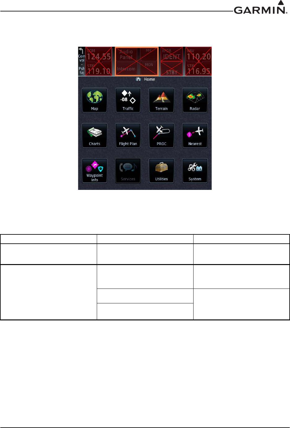
190-01007-A1 System Maintenance Manual GTN 6XX/7XX Part 23 AML STC
Rev. 7 Page 5-23
Figure 5-2. GMA 35 Failure Annunciation
5.7 GMA 35 System Messages
Table 5-15. Remote Audio Panel Alert Troubleshooting Guide
Alert Text Possible Cause Corrective Action
AUDIO PANEL - Audio panel
needs service.
Audio panel should be
serviced.
Return audio panel to Garmin
for service.
AUDIO PANEL - Audio panel is
inoperative or connection to
GTN is lost.
Audio panel is not powered up.
Ensure the audio panel is
receiving power and connected
to ground.
Audio panel has failed. Verify the wiring from the audio
panel to the GTN.
Wiring connections are
incorrect.
5.6 GMA 35 Failure Annunciations
Figure 5-2 depicts a typical failure indication of the GMA 35 audio panel.
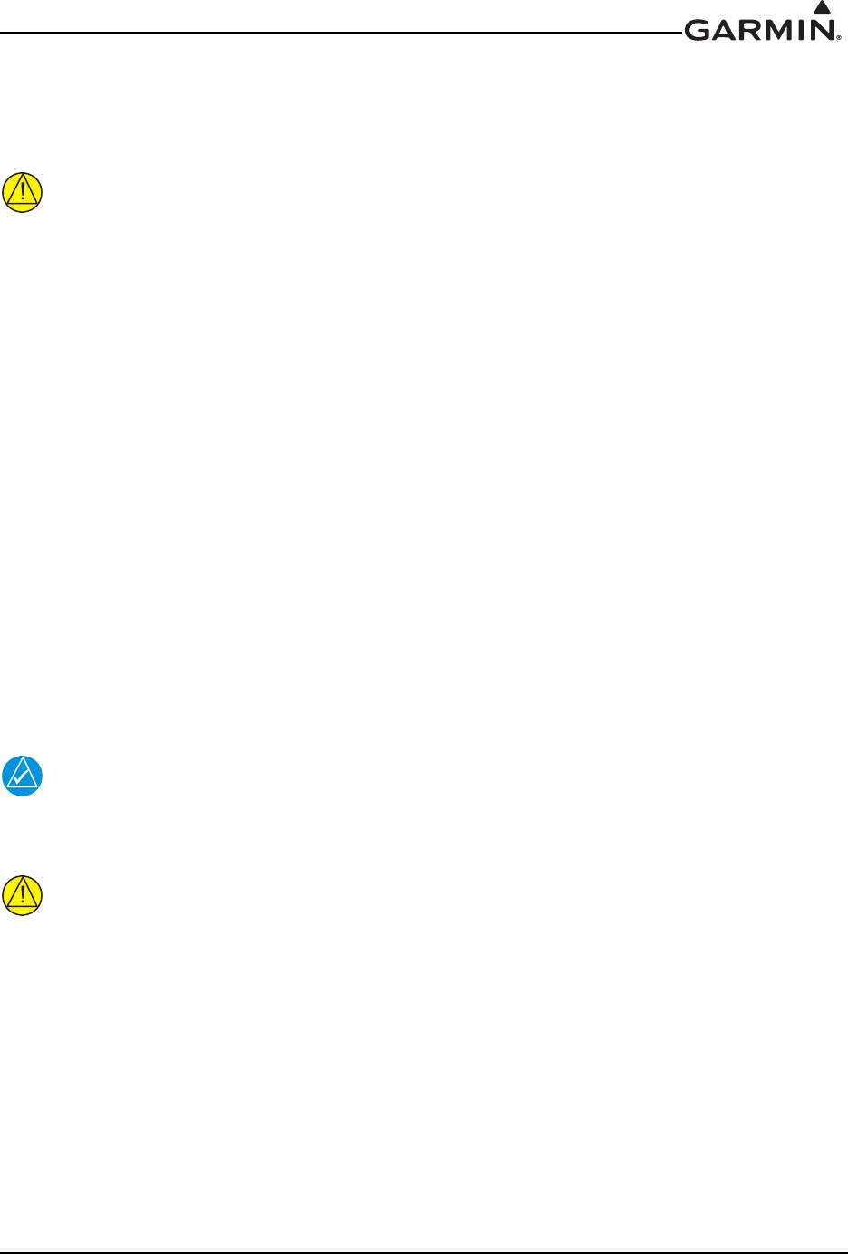
190-01007-A1 System Maintenance Manual GTN 6XX/7XX Part 23 AML STC
Rev. 7 Page 6-1
6 EQUIPMENT REMOVAL AND REINSTALLATION
This section describes how to remove and replace equipment associated with this STC. After removal and
reinstallation, LRUs must be configured and tested as described in Section 7.
CAUTION
When removing and/or replacing a GTN, GMA 35, or any other item under the scope of
the STC installation, always ensure that the aircraft power is off. Unplug any auxiliary
power supply.
6.1 GTN
Removal
1. Locate and pull the GTN GPS/NAV and COM (635/650/750 only) circuit breakers.
2. Locate the unit retention mechanism access hole at the bottom left corner of the unit face.
3. Insert a 3/32" hex tool into the access hole and turn the fastener counterclockwise until the unit is
forced out about 3/8" and can be freely pulled from the rack.
4. Slide the GTN unit out of the rack.
Reinstallation
1. Ensure that the GTN GPS/NAV and COM circuit breakers are pulled.
2. Slide the GTN straight into the rack until it stops about 1" short of the fully seated position.
3. Insert a 3/32" hex drive into the unit retention mechanism access hole at the bottom of the unit face
and turn the tool clockwise while pressing the bezel until the unit is firmly seated in the rack.
4. Once the GTN is reinstalled, verify that the unit power-up self test sequence is successfully
completed and no failure messages or configuration error messages are annunciated. Section 6.1.1
outlines the power-up self-test sequence.
NOTE
It may be necessary to insert the hex drive tool into the access hole and turn the cam
mechanism 90 degrees counterclockwise to ensure correct position prior to placing the
unit in the rack.
CAUTION
Be sure not to over-tighten the unit into the rack. The application of hex drive tool torque
exceeding 15 in-lbs can damage the locking mechanism.
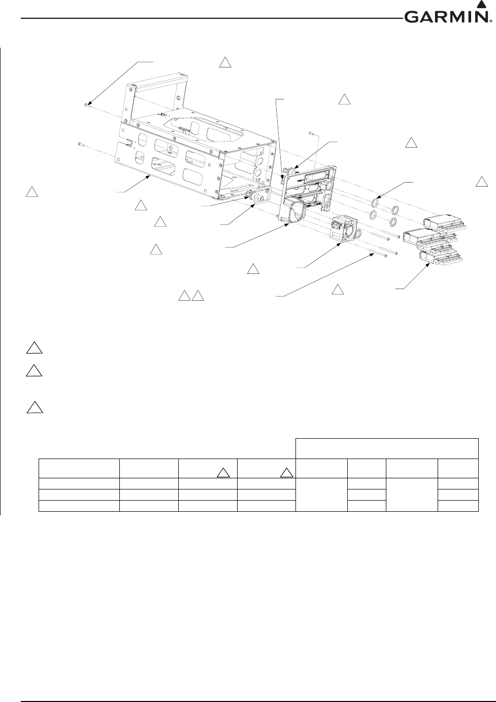
190-01007-A1 System Maintenance Manual GTN 6XX/7XX Part 23 AML STC
Rev. 7 Page 6-2
211-60234-08
SCREW, 4-40 x .25 (4X) 1
330-00053-02
BNC/TNC CONNECTOR 1
330-00053-01
BNC CONNECTOR 1
212-00022-00
SHOULDER WASHER 1
211-60234-23
SCREW, 4-40 x 1.375 (4X)
1 4
115-01294-00
GTN 7XX MOUNTING RACK
2
253-00421-00
CHASSIS GASKET
1
330-00053-01
BNC CONNECTOR
1
125-00221-10
GTN 7XX BACKPLATE
1
371-00014-01
FAN
1
011-02326-0X
CONNECTOR KIT
2
Figure 6-1. GTN 7XX Mounting Rack Assembly
1 PART OF 011-02246-00 (GTN 725, BLACK) AND 011-02246-02 (GTN 750, BLACK AND GRAY) KITS. SEE TABLE FOR
KIT CONTENT DIFFERENCES.
2 REFERENCE 010-00819-50 (GTN 725, BLACK), 010-00820-50 (GTN 750, BLACK) AND 010-00890-50 (GTN 750,
GRAY) KITS.
3 SEE TABLE FOR KIT REFERENCE INFORMATION.
4 TORQUE 4.5 - 5.2 IN-LBS
BACKPLATE KIT
CONTENT DIFFERENCES
UNIT DESCRIPTION INSTALLATION
KIT
CONNECTOR
KIT
BACKPLATE
KIT WASHER QTY
(EACH)
BNC
CONNECTOR
QTY
(EACH)
GTN 725 010-00819-50 011-02326-00 011-02246-00
212-00022-00
1
330-00053-02
0
GTN 750 (BLACK) 010-00820-50 011-02326-02 011-02246-02 3 2
GTN 750 (GRAY) 010-00890-50 011-02326-02 011-02246-02 3 2
2 2
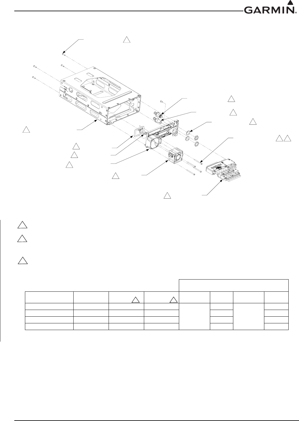
190-01007-A1 System Maintenance Manual GTN 6XX/7XX Part 23 AML STC
Rev. 7 Page 6-3
Figure 6-2. GTN 6XX Mounting Rack Assembly
211-60234-08
SCREW, 4-40 x .25 (4X) 1
330-00053-02
BNC/TNC CONNECTOR 1
330-00053-01
BNC CONNECTOR 1
212-00022-00
SHOULDER WASHER 1
211-60234-23
SCREW, 4-40 x 1.375 (4X) 1 4
115-01293-00
GTN 6XX MOUNTING RACK
2
253-00421-00
CHASSIS GASKET
1
330-00053-01
BNC CONNECTOR
1
125-00220-10
GTN 6XX BACKPLATE
1
371-00014-01
FAN
1
011-02325-0X
CONNECTOR KIT
2
1 PART OF 011-02245-00 (GTN 625, BLACK) 011-02245-01 (GTN 635, BLACK), AND 011-02245-02 (GTN 650, BLACK
AND GRAY) KITS. SEE TABLE FOR KIT CONTENT DIFFERENCES.
2 REFERENCE 010-00811-50 (GTN 625, BLACK), 010-00812-50 (GTN 635, BLACK), 010-00813-50 (GTN 650, BLACK),
AND 010-00889-50 (GTN 650, GRAY) KITS.
3 SEE TABLE FOR KIT REFERENCE INFORMATION.
4 TORQUE 4.5 - 5.2 IN-LBS
BACKPLATE KIT
CONTENT DIFFERENCES
UNIT DESCRIPTION INSTALLATION
KIT
CONNECTOR
KIT
BACKPLATE
KIT WASHER QTY
(EACH)
BNC
CONNECTOR
QTY
(EACH)
GTN 625 010-00811-50 011-02325-00 011-02245-00
212-00022-00
1
330-00053-01
0
GTN 635 010-00812-50 011-02325-01 011-02245-01 2 1
GTN 650 (BLACK) 010-00813-50 011-02325-02 011-02245-02 3 2
GTN 650 (GRAY) 010-00889-50 011-02325-02 011-02245-02 3 2
2 2

190-01007-A1 System Maintenance Manual GTN 6XX/7XX Part 23 AML STC
Rev. 7 Page 6-4
6.1.1 Display of Self-Test Data
Following normal power-up, the database pages are displayed, followed by the Instrument Panel Self-Test
page. Touch Continue to display the Instrument Panel Self-Test page. During this time, the electrical
outputs are activated and set to the values listed below. Touch Continue to acknowledge the Instrument
Panel Self-Test page. This is not a required check, although this page can be useful for troubleshooting
installation problems.
Table 6-1. Self-Test Values
Parameter Self-Test Value
Course Deviation Half-scale left deviation, TO indication, flag pulled
Glideslope/Vert. Deviation Half-scale up deviation, flag pulled
Annunciators All On
Selected Course (OBS) The GTN displays the OBS value (149.5° if interfaced to an HSI with
driven course pointer).
Desired Track 149.5° (Displayed as 150°)
Items below are not displayed on the Instrument Panel Self-Test page
Distance to Go 10.0 nautical miles
Time to Go 4 minutes
Bearing to Waypoint (RMI) 135°
Active Waypoint “GARMN”
Groundspeed 150 knots
Present Position N 39°04.05’, W 94°53.86’
Waypoint Alert Active
Phase of Flight En Route
Message Alert Active
Leg/OBS Mode Leg Mode
GPS Integrity Invalid
Roll Steering (if applicable)
Flight Director commands 0° bank (level flight) for 5 seconds; com-
mands increasing right bank at 1°/second for 5 seconds; commands
5° right bank for 5 seconds; commands decreasing right bank at 1°/
second for 5 seconds, until command is 0° bank again. This cycle
repeats continuously.
190-01007-A1 System Maintenance Manual GTN 6XX/7XX Part 23 AML STC
Rev. 7 Page 6-5
6.2 GMA 35
Removal
1. Locate and pull the audio panel circuit breaker.
2. Ensure that the GTN(s) are not receiving power prior to removal of the audio panel.
3. Remove the GTN 7XX.
4. Locate the GMA 35 unit retention mechanism access hole at the bottom center of the unit face.
5. Insert a 3/32" hex tool into the access hole and turn the fastener counterclockwise until the unit is
forced out about 3/8" and can be freely pulled from the rack
6. Slide the GMA 35 unit out of the rack.
Reinstallation
1. Ensure that the audio panel circuit breaker is pulled and the GTN units are not receiving power.
2. Slide the GMA 35 straight into the rack until it stops.
3. Insert a 3/32" hex drive into the unit retention mechanism access hole at the bottom of the unit face
and turn the tool clockwise while pressing on the face of the unit until the GMA 35 is firmly seated
in the rack.
4. Reinstall the GTN 7XX.
5. Verify that there are no failure messages or annunciations when the GTN and audio panel is
powered on.
CAUTION
Be sure not to over tighten the unit into the rack. The application of hex drive tool torque
exceeding 15 in-lbs can damage the locking mechanism.
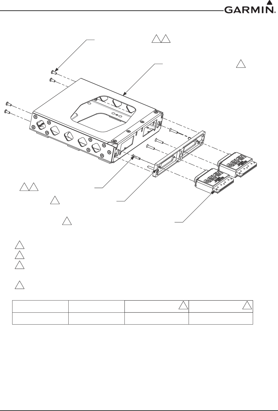
190-01007-A1 System Maintenance Manual GTN 6XX/7XX Part 23 AML STC
Rev. 7 Page 6-6
Figure 6-3. GMA 35 Mounting Rack Assembly Overview
3$572)%$&.3/$7(.,7
3$572)&211(&725.,7
6&5(:;
*0$02817,1*5$&.
%$&.6+(//;
*5281'$'$37(5;
&211(&725;
3,16$5
*0$%$&.3/$7(
6&5(:;
6((7$%/()25.,75()(5(1&(,1)250$7,21
3$572),167$//$7,21.,7
72548(±,1/%6
*0$
81,7'(6&5,37,21
&211(&725.,7
%$&.3/$7(.,7
,167$//$7,21.,7

190-01007-A1 System Maintenance Manual GTN 6XX/7XX Part 23 AML STC
Rev. 7 Page 6-7
6.3 Data Card
CAUTION
Handle the data cards carefully. Do not touch the connector edge of the data card.
To replace the data card, complete the following steps:
1. Ensure that the GTN is turned off.
2. Remove the data card by pressing the card until it disengages and then pull the data card to extract
from the unit.
With the label facing right, insert the new data card by pushing the card straight into the slot and press until
it is fully inserted.
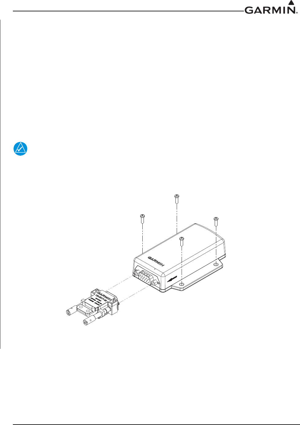
190-01007-A1 System Maintenance Manual GTN 6XX/7XX Part 23 AML STC
Rev. 7 Page 6-8
6.4 Flight Stream 210
See Figure 6-4 when performing the following steps:
Removal
1. Locate and pull the BT Link circuit breaker.
2. Unscrew the two jackscrews on the Flight Stream connector. Remove connector.
3. Locate the four #6 mounting screws for the unit and unscrew them, removing the Flight Stream
device.
Reinstallation
1. Check that the BT Link circuit breaker is pulled.
2. Reinstall the Flight Stream device using the four previously removed #6 mounting screws. Tighten
fasteners until snug and turn an additional one-quarter turn.
NOTE
Ensure that the Flight Stream is mounted with the arrow pointing in the direction of flight.
3. Attach the connector, tightening the two jackscrews.
4. Push in the BT Link circuit breaker.
Figure 6-4. Flight Stream Assembly Overview
(bonding strap not shown)
DIRECTION OF FLIGHT
FLIGHT STREAM 210: P/N 011-03257-40
CONNECTOR KIT ASSEMBLY: P/N 011-03258-00
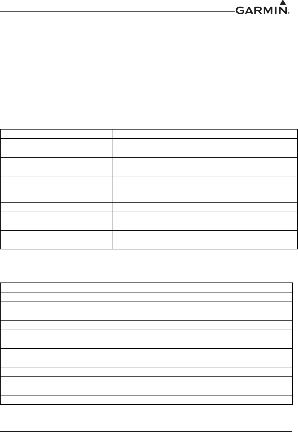
190-01007-A1 System Maintenance Manual GTN 6XX/7XX Part 23 AML STC
Rev. 7 Page 6-9
6.5 NAV Antenna Cable Diplexer
Removal
1. Disconnect the coaxial connectors from diplexer, taking note of which coaxial connectors are
connected to each port on the diplexer.
2. Remove the mounting screws and diplexer.
Reinstallation
1. Reinstall the diplexer over the existing hole pattern and reinstall fasteners. Torque fasteners within
22 to 25 in-lbs.
2. Reconnect the coaxial connectors to the diplexer.
Approved Hardware for Replacement:
Stainless Hardware
Note: Part numbers in parentheses are inactive or cancelled part numbers; these numbers may still be
available and/or referenced on packaging material.
Steel Hardware
Note: Part numbers in parentheses are inactive or cancelled part numbers; these numbers may still be
available and/or referenced on packaging material.
Name Part Number
Screw, Pan Head, Stainless NASM51958, (MS51958), (AN520C)
Washer, .032 thickness NAS1149C0332R, (AN960C-10L)
Washer, .063 thickness NAS1149F0363P, (AN960C-10)
Nut, Self-locking Metal, Hex, Thin NASM21043-3, NAS1291C3, (MS21043-3)
Nut, Self-locking Metal, Hex NASM21046C3, MS20365C1032C, NAS1021C3,
(MS21046C3), (AN363C1032)
Nutplate, One Lug, Fixed MS21052, MS21054, MS21072
Nutplate, One Lug, Floating MS21062
Nutplate, Two Lug, Fixed MS21048, MS21050, MS21070
Nutplate, Two Lug, Floating MS21060, MS21076
Nutplate, Corner MS21056, MS21058, MS21074
Nutplate, Side-by-side MS21087
Name Part Number
Screw, Pan Head, Low Carbon Steel NASM35207, (MS35207), (AN520)
Screw, Pan Head, Alloy Steel NAS603
Washer, .032 thickness NAS1149F0332P, (AN960-10L)
Washer, .063 thickness NAS1149F0363P, (AN960-10)
Nut, Self-locking Metal, Hex, Thin NASM21042L3, NAS1291-3, (MS21042L3)
Nut, Self-locking Metal, Hex NASM21045L3, (MS21045L3), (AN363-1032)
Nutplate, One Lug, Fixed MS21051, MS21053, MS21071
Nutplate, One Lug, Floating MS21061
Nutplate, Two Lug, Fixed MS21047, MS21049, MS21069
Nutplate, Two Lug, Floating MS21059, MS21075
Nutplate, Corner MS21055, MS21057, MS21073
Nutplate, Side-by-side MS21086

190-01007-A1 System Maintenance Manual GTN 6XX/7XX Part 23 AML STC
Rev. 7 Page 6-10
6.6 NAV Antenna Cable Splitter
Removal
1. Disconnect the coaxial connectors from splitter, taking note of which coaxial connectors are
connected to each port on the splitter.
2. Remove the mounting screws and splitter.
Reinstallation
1. Reinstall the splitter over the existing hole pattern and reinstall fasteners. Torque fasteners within
5 to 6 in-lbs.
2. Reconnect the coaxial connectors to the splitter.
Approved Hardware for Replacement
Stainless Hardware
Note: Part numbers in parentheses are inactive or cancelled part numbers; these numbers may still be
available and/or referenced on packaging material.
Steel Hardware
Note: Part numbers in parentheses are inactive or cancelled part numbers; these numbers may still be
available and/or referenced on packaging material.
Name Part Number
Screw, Pan Head, Stainless MS51957, (AN515C)
Washer, .016 thickness NAS1149CN416R, (AN960C-4L)
Washer, .032 thickness NAS1149CN432R, (AN960C-4)
Nut, Self-locking Metal, Hex, Thin NASM21043-04, NAS1291C04, (MS21043-04)
Nut, Self-locking Metal, Hex NASM21046C04, (MS21046C04)
Nutplate, One Lug, Fixed MS21052, MS21054, MS21072
Nutplate, One Lug, Floating MS21062
Nutplate, Two Lug, Fixed MS21048, MS21050, MS21070
Nutplate, Two Lug, Floating MS21060, MS21076
Nutplate, Corner MS21056, MS21058, MS21074
Nutplate, Side-by-side MS21087
Name Part Number
Screw, Pan Head, Low Carbon Steel NASM35206, (MS35206), (AN515)
Screw, Pan Head, Alloy Steel NAS600
Washer, .016 thickness NAS1149FN416P, (AN960-4L)
Washer, . 032 thickness NAS1149FN432P, (AN960-4)
Nut, Self-locking Metal, Hex, Thin NASM21042L04, NAS1291-04, (MS21042L04)
Nut, Self-locking Metal, Hex NASM21045L04, (MS21045L04)
Nutplate, One Lug, Fixed MS21051, MS21053, MS21071
Nutplate, One Lug, Floating MS21061
Nutplate, Two Lug, Fixed MS21047, MS21049, MS21069
Nutplate, Two Lug, Floating MS21059, MS21075
Nutplate, Corner MS21055, MS21057, MS21073
Nutplate, Side-by-side MS21086

190-01007-A1 System Maintenance Manual GTN 6XX/7XX Part 23 AML STC
Rev. 7 Page 6-11
6.7 Configuration Module (P1001 Only)
GTN P1001 connector assemblies serve as the housing for a configuration module. This section lists
configuration module assemblies.
Table 6-2. Configuration Module Wire Color Reference Chart
NOTE
The pin contacts supplied with the GTN configuration module are specifically made to
accommodate 28 AWG wire. The crimp tool should have the indenter set to the correct
setting when crimping these contacts to the configuration module harness.
Configuration modules are located within the GTN harness connector backshell (Item 6, Figure 6-5).
There are two configuration module kits that have been approved for use with the GTNs.
The 011-00979-00 configuration module kit has a spacer (Figure 6-4), while the 011-00979-03
configuration module kit does not (Figure 6-3). The 011-00979-03 configuration module kit is
recommended for all replacements. The instructions for removal/replacement of a configuration module
apply equally to either P/N. Unless otherwise noted, refer to the corresponding backshell assembly
drawing when performing the following removal and reinstallation steps.
Color Function P1001 Contact
Red Vcc 65
Black Ground 64
Yellow Data 62
White Clock 63
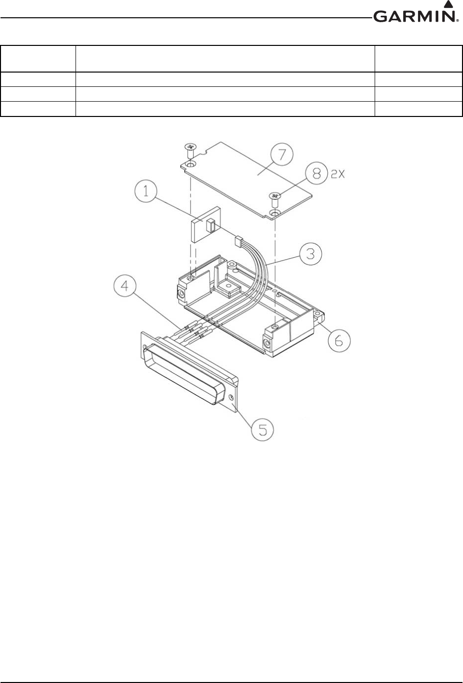
190-01007-A1 System Maintenance Manual GTN 6XX/7XX Part 23 AML STC
Rev. 7 Page 6-12
Table 6-3. Configuration Module Kit 011-00979-03 (P1001)
Figure 6-5. Backshell Assembly (Potted Configuration Module)
Removal
1. Disconnect the connector from the GTN backplate assembly.
2. Remove two screws (8) from cover (7) and remove cover. See Figure 6-5 for this step.
3. Unplug the connector from the configuration module (1).
4. Remove the configuration module from the backshell connector.
Reinstallation
1. Inspect the connector for damaged pins (4).
2. Place the configuration module (1) in position.
3. Insert connector into the configuration module (1).
4. Place the cover (7) back on the connector and reinstall screws (8). See Figure 6-5 for this step.
Figure 6-5
Reference Description Garmin P/N
1 Configuration Module, PCB Board Assembly w/EEPROM 011-02178-00
3 4-Conductor Harness 325-00122-00
4 Pin Contact, Crimp, #22D 336-00021-00
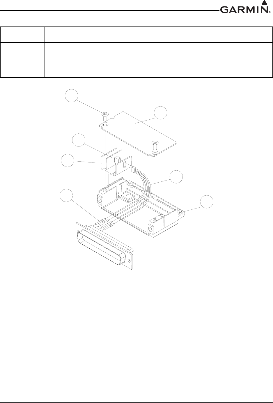
190-01007-A1 System Maintenance Manual GTN 6XX/7XX Part 23 AML STC
Rev. 7 Page 6-13
Table 6-4. Configuration Module Kit 011-00979-00 (P1001)
Figure 6-6. Backshell Assembly (Configuration Module with Spacer)
Removal
1. Disconnect the connector from the GTN.
2. Remove two screws (5) from cover (6) and remove cover.
3. Unplug the connector from the configuration module (1).
4. Remove the configuration module from the backshell connector.
Reinstallation
1. Inspect the connector for damaged pins (4).
2. Apply spacer (2) by wrapping it around the PCB board (1) making sure to insert the plastic
connector mounted on the board into the hole provided in the spacer.
3. Place the configuration module (1) in position.
4. Insert connector into the configuration module (1).
5. Place the cover (6) back on the connector and reinstall screws (5).
Figure 6-6
Reference Description Garmin P/N
1 Configuration Module, PCB Board Assembly w/EEPROM 012-00605-00
2 Spacer, Configuration Module 213-00043-00
3 4-Conductor Harness 325-00122-00
4 Pin Contact, Crimp, #22D 336-00021-00
[
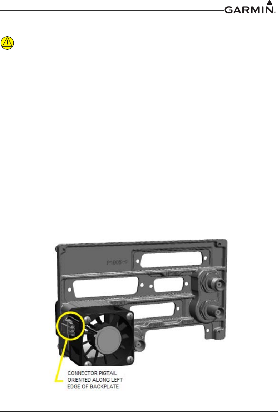
190-01007-A1 System Maintenance Manual GTN 6XX/7XX Part 23 AML STC
Rev. 7 Page 6-14
6.8 GTN Fan
CAUTION
To avoid damage to the GTN, take precautions to prevent Electro-Static Discharge (ESD)
when handling the GTN, connectors, fan, and associated wiring. ESD damage can be
prevented by touching an object that is of the same electrical potential as the GTN before
handling the GTN itself.
The GTN cooling fan assembly is located behind the rack relative to the unit. Fan removal and replacement
details for specific installations fall outside the scope of this manual.
Removal
1. Remove power from aircraft.
2. Remove the GTN unit from the rack. Refer to Section 6.1.
3. Loosen the four 4-40 x 0.25" panhead screws at each corner of the inside rear wall of the rack.
4. While depressing the metal spring at the lower left hand corner of the rack’s rear face, slide the
connector backplate to the left. The connector backplate is now free of the rack.
5. Disconnect the fan power connector. Be careful to avoid damaging the fan wires.
6. Remove the four 4-40 x 1.375" panhead screws attaching the fan to the backplate.
Reinstallation
1. Position the fan on the backplate with the fan connector pigtail oriented along the left edge of the
backplate, as shown in Figure 6-7.
2. Reinstall screws.
3. Connect fan power connector.
Figure 6-7. Fan/Backplate Orientation (GTN 7XX)

190-01007-A1 System Maintenance Manual GTN 6XX/7XX Part 23 AML STC
Rev. 7 Page 6-15
Table 6-5 lists part numbers for the Fan Kit which is used with P1001 only.
Table 6-5. Fan Kit
Table 6-6. Fan Cable Wire Color Reference Chart
Fan Wiring Harness Replacement
1. Strip 0.17" of insulation from each wire prior to crimping. Crimp socket contacts onto each wire of
the three-conductor wire harness. Insert newly crimped socket contacts and wires into the
appropriate connector housing location as shown in Figure 6-8.
2. Plug the three-conductor wire harness connector into the connector on the fan.
Figure 6-8 Ref Description Garmin P/N
1 Fan Cable Assembly, 3 conductor harness 320-00600-00
2 Pin Contact, Crimp, #22D 336-00021-00
3 Silicon Fusion Tape 249-00114-00
Color Function P1001 Contact
Red Power 59
Black Ground 43
Yellow Fan tach 58
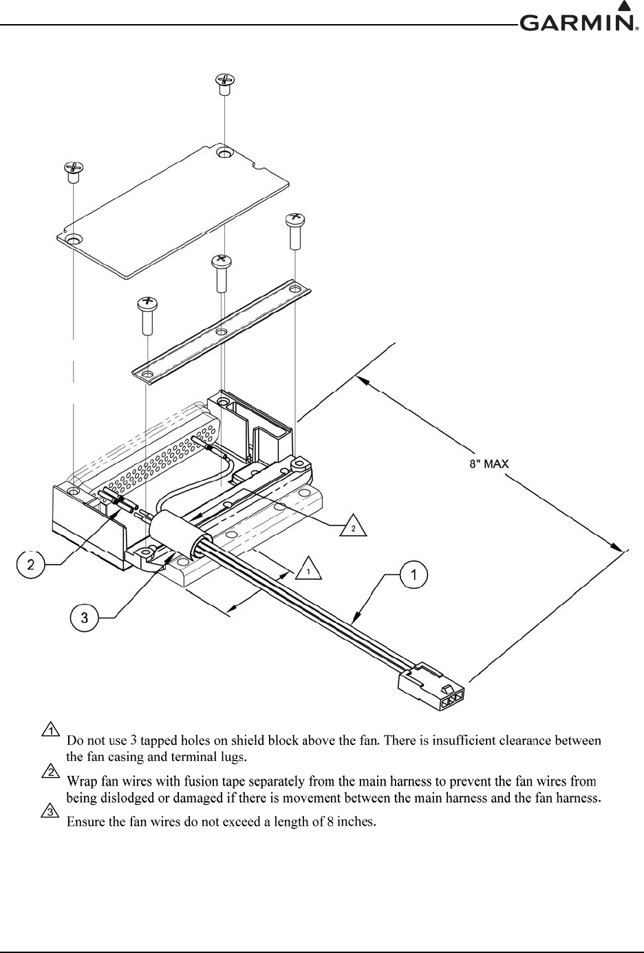
190-01007-A1 System Maintenance Manual GTN 6XX/7XX Part 23 AML STC
Rev. 7 Page 6-16
Figure 6-8. Fan Wiring Replacement
190-01007-A1 System Maintenance Manual GTN 6XX/7XX Part 23 AML STC
Rev. 7 Page 6-17
6.9 TVS and Fuse (Nonmetallic Aircraft Only)
This section applies to IFR nonmetallic aircraft only. VFR nonmetallic aircraft do not require the use of
TVSs or fuses.
Certain nonmetallic aircraft will require TVSs at the main power input of the GTN. Refer to the
GTN 6XX/7XX AML STC Installation Manual for TVS component part numbers.
6.9.1 Fuse
Removal
1. Open the fuse holder and remove the fuse.
Reinstallation or Replacement
1. If the fuse continuity checks good, reinstall fuse and close the fuse holder. If the fuse is open,
replace the fuse and close the fuse holder.
6.9.2 TVS
TVS1 Removal
1. Remove the shield block grounding screw and remove the ring terminal from the backshell of the
connector as shown in Figure 6-9.
2. Open the fuse holder and remove the fuse.
3. Carefully remove heat shrink from the TVS ensuring not to cut the insulation on the wire under the
heat shrink.
4. On the fuse end of the TVS, use a soldering iron to heat the solder joint to remove the TVS.
TVS1 Replacement
CAUTION
Be aware of the orientation of the TVS during replacement. Refer to Figure 6-9 for proper
alignment of the TVS.
1. Solder new TVS onto the exposed wire from the fuse holder.
2. Solder a small piece of wire to the opposite end of the TVS. The total wire length to the
environmental splice is not to exceed 6".
3. Install heat shrink over the exposed TVS and solder joints.
4. Attach the ring terminal to the new lead as shown in Figure 6-9.
5. Place the fuse back into the fuse holder and close the holder.
6. Reattach the ring terminal to the backshell of the connector.
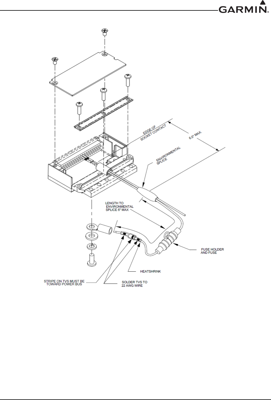
190-01007-A1 System Maintenance Manual GTN 6XX/7XX Part 23 AML STC
Rev. 7 Page 6-18
Figure 6-9. TVS/Fuse Replacement (TVS1/F1)
TVS2 Removal
1. Remove the ring terminal from ground as shown in Figure 6-11.
2. Carefully remove heat shrink from the TVS assembly, ensuring not to cut the insulation on the
wire under the heat shrink.
3. If replacing the entire TVS assembly, unplug the 4-pin connector and proceed to step (1) of the
replacement. If it is not necessary to replace all of the TVSs, carefully unpin the failed TVS(s).
4. Apply heat with a soldering iron to opposite end of the TVS assembly so that the bad TVSs can be
removed. Use caution when applying heat to the solder joint to ensure that the remaining TVSs
aren’t damaged.
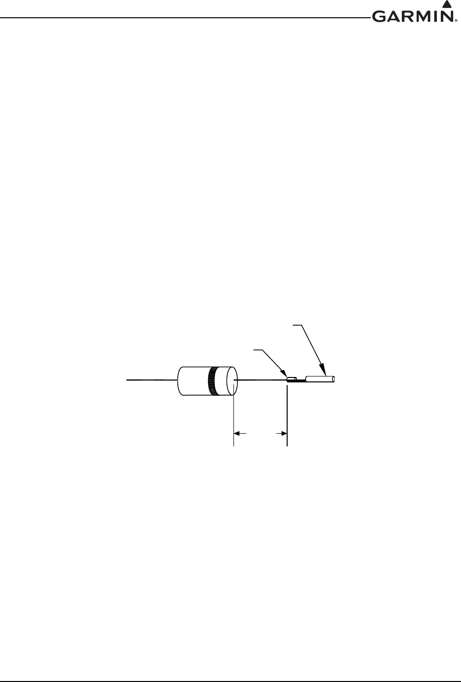
190-01007-A1 System Maintenance Manual GTN 6XX/7XX Part 23 AML STC
Rev. 7 Page 6-19
TVS2 Replacement
1. When installing new TVSs, cut the leads to 0.75 +0.00/-0.10" on both sides.
2. Crimp and solder each of the TVS banded side (cathode) leads to their specific sockets (refer to
Figure 6-10), and insert into the 4-pin connector with sockets.
3. Install heat shrink around the four TVSs – this will help to hold them in place during the following
steps.
4. Solder the un-banded end of the TVS assembly together as shown in Figure 6-11 onto a length of
18 AWG wire. Attach a terminal lug onto the wire end.
5. Carefully remove heat shrink installed in Step 3 from the TVS ensuring not to cut the insulation on
the wire under the heat shrink.
6. Attach an appropriately sized section of heat shrink to cover the soldered TVS leads and four TVS
pieces. A second appropriately sized (larger) section of heat shrink should then be attached to
shrink over the 4-pin connector with sockets and back over the four TVSs. These two pieces of
heat shrink should overlap along the entire length of the TVSs.
7. Mate the four-pin connector together.
8. Reconnect the power end of the assembly to the power bus
9. Reconnect the ground end of the assembly to ground.
10. Perform a polarity check per Section 6.9.2.1.
Figure 6-10. Detail of TVS Pin Assembly
0$;
62&.(7&217$&7
&5,03$1'62/'(5
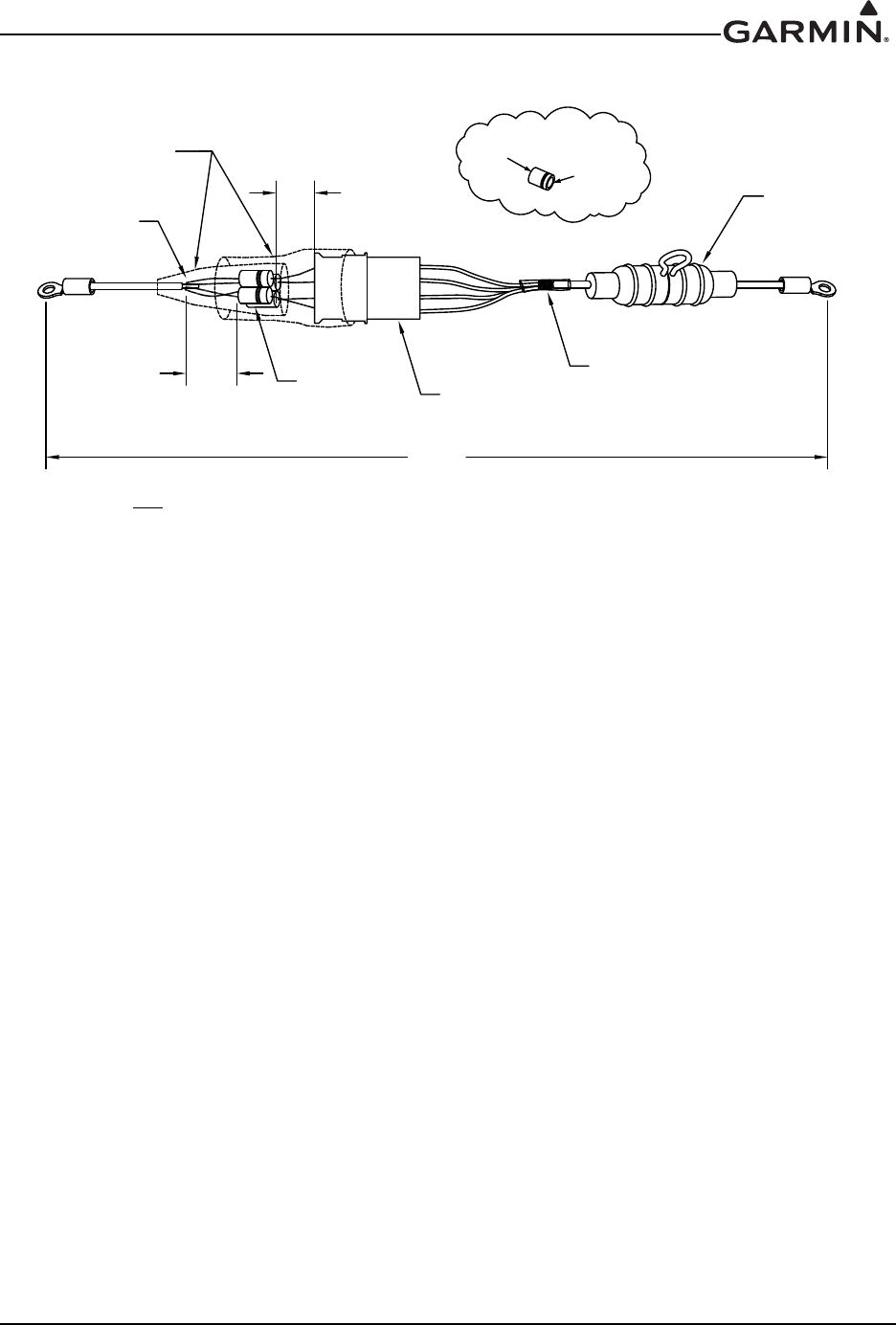
190-01007-A1 System Maintenance Manual GTN 6XX/7XX Part 23 AML STC
Rev. 7 Page 6-20
Figure 6-11. TVS2 Assembly
6.9.2.1 TVS2 Assembly Polarity Check
Using a multimeter that is set to the diode mode, check conductivity across the entire TVS2 assembly. In
one direction, the meter should read open and in the other direction it should read 2.0 to 2.5 volts. When
installed in the aircraft, the TVS assembly should be oriented so that it does not normally conduct from
power to ground. The meter should indicate open when the red lead is attached to the power bus terminal
lug, and the black lead is attached to the ground terminal lug. The meter should indicate 2.0 to 2.5 volts
when the red lead is attached to the ground terminal lug, and the black lead is attached to the power bus
terminal lug.
+($76+5,1.
)86(
+2/'(5
7964W\
0D[
0D[
62/'(5
72
*5281' 7232:(5
%86
$12'(
&$7+2'(
'(7$,/2)796
0D[
3LQ&RQQHFWRU
(QYLURQPHQWDO6SOLFH
127(
$OOIRXU796VPXVWEHLQVWDOOHGZLWKWKHFDWKRGHIDFLQJWKHFRQQHFWRU

190-01007-A1 System Maintenance Manual GTN 6XX/7XX Part 23 AML STC
Rev. 7 Page 6-21
6.10 GPS/SBAS Antenna Cable Overbraid
The following removal and replacement steps are provided as guidance for replacing the cable overbraid
assembly. See Figure 6-12.
Removal
1. Gain access to the GPS/SBAS antenna cable.
2. Disconnect the overbraid terminal lug from the shield block.
3. Disconnect the GPS coaxial cable connector at the GTN backplate.
4. Gain access to the GPS antenna and disconnect the antenna end of the coaxial cable.
5. Refer to the wire routing diagram and remove the entire cable assembly from the aircraft.
6. Remove the two visible electrical tie down connectors.
7. Unfold the overbraid that is doubled over and remove the remaining tie down connector.
8. Remove the antenna cable from the overbraid and visually inspect the cable insulation for damage.
Replacement
NOTE
Note: The length of overbraid required for replacement of the assembly will be the length
of the GPS/SBAS antenna cable plus 6". Refer to Figure 6-12 before beginning the
reinstallation steps below.
1. If the antenna cable insulation shows signs of damage, replace the cable.
2. Test the GPS coaxial cable for continuity. Replace the cable if it fails the continuity test.
3. Slide the new overbraid over the entire length of the GPS/SBAS antenna cable.
4. Roll back approximately 1.5" of the overbraid end at the antenna end.
5. Leaving the rolled-back portion free, secure the antenna end of the overbraid around the
GPS/SBAS antenna connector with an electrical tie-down strap.
6. Fold the free overbraid ends back over the tie-down strap and secure them to the cable with two
additional tie-down straps.
7. Reinstall the cable in the aircraft and connect the cable to the GPS antenna.
8. At the GTN end of the overbraid, comb out a maximum of two" of braid, twist it, cut to length if
necessary, and terminate with a #10 terminal lug.
9. Connect the remaining end of the antenna cable to the GTN and terminal lug to the P1001 shield
block ground.
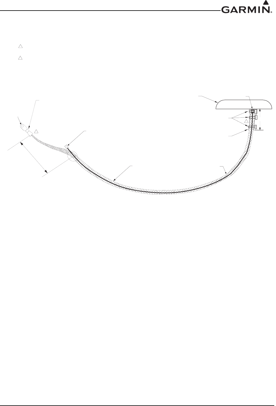
190-01007-A1 System Maintenance Manual GTN 6XX/7XX Part 23 AML STC
Rev. 7 Page 6-22
Figure 6-12. GPS/SBAS Antenna Cable Overbraid
#8 TERMINAL LUG
MS25036-156
OVERBRAID
AIRCRAFT SPRUCE P/N 863
NOTES:
THE OVERBRAID MUST BE INSERTED INTO THE GROUNDING LUG BY COMBING OUT AND
TWISTING THE WIRE STRANDS AND BEFORE TERMINATING THEM IN A TERMINAL LUG .
CABLE TIE DOWN
MS3367-1-X
3 PLCS
1.5"
OVERBRAID DOUBLED BACK
ON SELF
ANTENNA
CONNECTOR
1
TO GPS ANTENNA CONNECTOR
ON GTN BACKPLATE
OVERBRAID INTSTALLED OVER ENTIRE
LENGTH OF THE GPS ANTENNA CABLE
GPS/SBAS ANTENNA
2" MAX
WHEN REINSTALLING OVERBRAID AT CONNECTOR END OF PIGTAIL, THE OVERBRAID IS
PUSHED DOWN UNTIL IT TOUCHES THE TOP SURFACE OF THE CONNECTOR.
CONTINUE PUSHING BRAID DOWN BY SPREADING IT OUT ALONG THE TOP SURFACE
OF THE CONNECTOR. APPLY THE FIRST CABLE TIE AROUND THE BRAID AND ANTENNA
CABLE WHERE IT ENTERS THE CONNECTOR. THEN LIFT THE SPREAD PORTION OF
THE BRAID UP TO COVER THE FIRST CABLE TIE, DOUBLING BACK ON ITSELF. INSTALL
THE REMAINING TWO CABLE TIES ABOVE THE BULGE CREATED BY THE FIRST CABLE
TIE WHICH IS NOW COVERED BY THE BRAID.
CONNECT TO P1001
SHIELD BLOCK
GROUND
2
2
1

190-01007-A1 System Maintenance Manual GTN 6XX/7XX Part 23 AML STC
Rev. 7 Page 6-23
6.11 WXR HSDB Cable Overbraid
The following removal and replacement steps are provided as guidance for replacing the cable overbraid
assembly. The overbraid assembly drawing is shown in Figure 6-13.
Removal
1. Remove the radome to gain access to the GWX radar.
2. Disconnect the cable connector at the weather radar.
3. At the other end of the overbraid, disconnect the terminal ground lug from the bulkhead.
4. Remove the electrical tie-down strap.
5. Remove the backshell from the GWX weather radar connector.
6. Unpin the necessary cables from the GWX connector and pull the overbraid off of the wire.
Replacement
NOTE
The length of overbraid required is approximately equal to the length of the WXR cabling
in the radome area (measured from the bulkhead to the WXR R/T connector) plus 6".
1. If any of the cables’ insulation shows signs of damage, replace the cable(s).
2. Slide the new overbraid over the HSDB cabling from the WXR R/T to the bulkhead.
3. At the bulkhead end of the overbraid, comb out a maximum of two" of braid, twist it, cut to length
if necessary, and terminate with a MS20659-131 5/16” terminal lug.
4. With a NASM970-516 (AN970-516) washer between the terminal lug and bulkhead, secure the
terminal lug to the existing bulkhead location.
5. At the WXR R/T end of the overbraid, fold one" of overbraid back over itself. Position the
overbraid so that the fold will lie under the backshell cover plate, while the overbraid ends will lie
just outside the strain relief bar.
6. Re-pin the cables to the WXR connector and reinstall the backshell cover plate and strain relief
bar.
7. Verify overbraid terminal bonding by checking the resistance between the overbraid and the
bulkhead. The resistance should be less than 2.5 mΩ.
CAUTION
All overbraid ends must be secured outside the backshell by the strain relief bar (Refer to
Figure 6-13). Failure to do so may allow the overbraid ends to contact and short HSDB
pins, resulting in weather radar malfunction or damage.
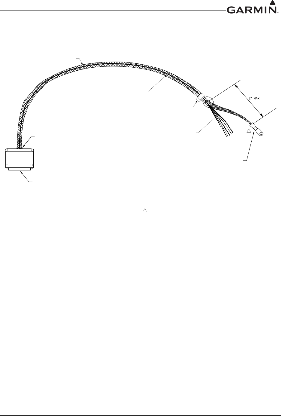
190-01007-A1 System Maintenance Manual GTN 6XX/7XX Part 23 AML STC
Rev. 7 Page 6-24
Figure 6-13. WXR HSDB Cable Overbraid Details
Sheet 1 of 2
7(50,1$//8*
06
29(5%5$,'
44%57
25
44%)7
127(6
7+(29(5%5$,'0867%(,16(57(',1727+(*5281',1*/8*%<&20%,1*,7287
,172$)/$7&21),*85$7,21$1'7+(1&2035(66,172$60$//',$0(7(5%81'/(
1($5,76(1':+,&+0$<%(,16(57(',1727+(*5281',1*/8*
:($7+(55$'$5
&211(&725
$//+6'%&$%/,1*7+$7(17(567+(
0(7$/)86(/$*(
29(5%5$,',167$//('29(5:($7+(5
5$'$5&$%/,1*7+$7,6,15$'20($5($
35,2572(17(5,1*7+(0(7$/)86(/$*(
29(5%5$,'(1'6
(QVXUHWKDWWKH
RYHUEUDLGGRHVQRW
SURWUXGHPRUHWKDQó´
SDVWWKHVWUDLQUHOLHIEDU
LQWRWKHEDFNVKHOO
(/(&75,&$/7,('2:1675$3
06^RU`;
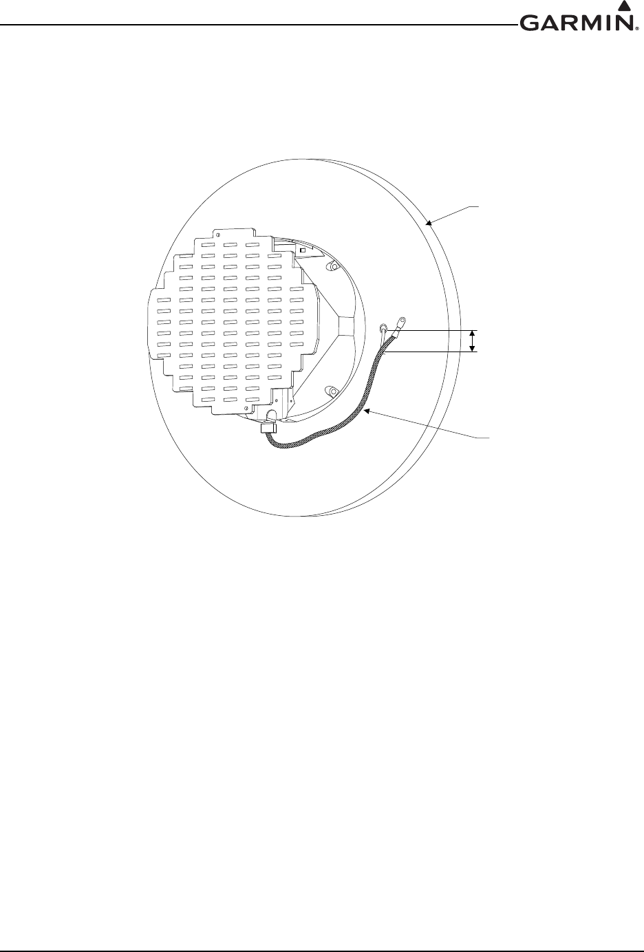
190-01007-A1 System Maintenance Manual GTN 6XX/7XX Part 23 AML STC
Rev. 7 Page 6-25
Figure 6-12. WXR HSDB Cable Overbraid Details
Sheet 2 of 2
%8/.+($'
29(5%5$,'
0$;,080
(;326('&$%/(
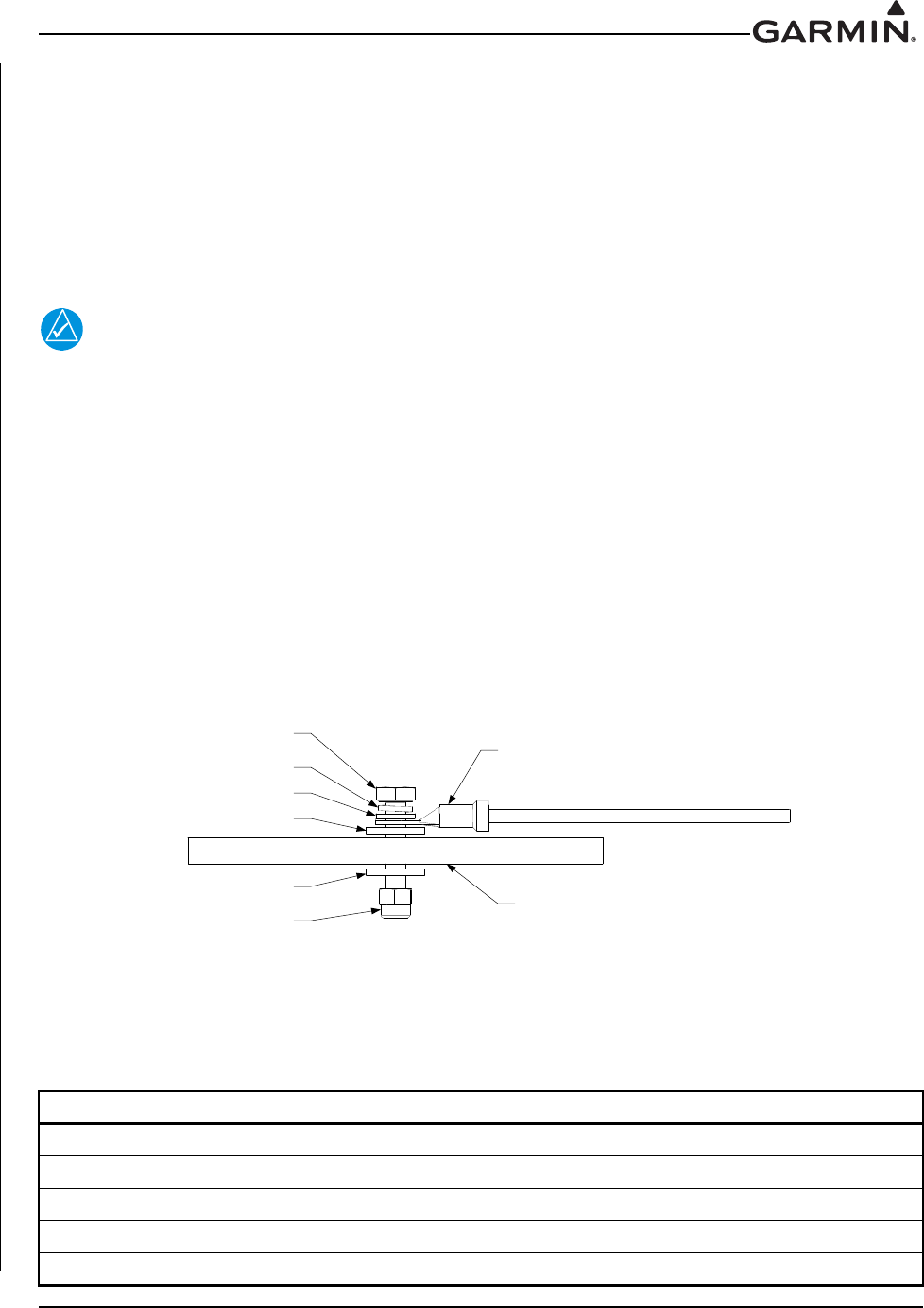
190-01007-A1 System Maintenance Manual GTN 6XX/7XX Part 23 AML STC
Rev. 7 Page 6-26
6.12 Instrument Panel Bonding Strap
The following steps are provided as guidance for replacing a damaged instrument panel bonding strap.
Reference the bonding strap hardware stack up in Figure 6-14.
Removal
The bonding strap is attached in two locations. The terminal lug is secured with a lock nut. To remove the
strap, access both sides of the instrument panel and the nearby structure and unbolt the hardware.
Replacement
NOTE
The instrument panel bonding strap should be as short as practical and must not exceed
6” in length.
1. Construct a bonding strap by attaching 5/16" inside diameter insulated terminal lugs
(MS20659-131) to both ends of the braid. 3/4" tinned copper flat braid (QQB575F36T781) or
equivalent may be used.
2. If needed, clean the attachment locations with a bonding brush.
3. Secure each end of the bonding strap to the previously installed locations. Ensure that the strap
does not loop back on itself and that the hardware is as shown in Figure 6-14. The washers must
seat fully against the aircraft metallic structure, without overhang or interference from other
hardware.
4. Using a milliohm meter, verify that the resistance between the connected structure is less than 2.5
milliohms.
Figure 6-14. Instrument Panel Bonding
Table 6-7. Instrument Panel Bonding Hardware
Hardware P/N
Bolt AN5-XA
Washer 1 (5/16" lock washer) NASM35338-45
Washer 2 (5/16" flat washer) NAS1149F0532P
Washer 3 (.063" thick flat washer) NASM970-516 or AN970-5
Locknut (5/16") MS21042, MS20364, MS21045, or MS20365
BOLT
WASHER 1
WASHER 2
WASHER 3
WASHER 3
LOCK NUT
LUG
INSTRUMENT PANEL

190-01007-A1 System Maintenance Manual GTN 6XX/7XX Part 23 AML STC
Rev. 7 Page 6-27
6.13 Flight Stream 210 Bonding Strap
The following removal and replacement steps are provided as guidance for replacing the Flight Stream
bonding strap. The bonding strap assembly drawing is shown in Figure 6-15.
NOTE
Aircraft structure side of bonding strap may be mounted using a nut in lieu of a nut plate.
If a nut was used in lieu of a nut plate, further disassembly of the aircraft may be required
to gain access to the nut.
Removal
1. Disconnect one end of the bonding strap from the aircraft ground location.
2. Disconnect the other end of the bonding strap from the shield block on the Flight Stream connector
backshell.
3. Remove the bonding strap.
Replacement
NOTE
The Flight Stream bonding strap should be as short as practical and must not exceed 20".
When installed, the bonding strap must not loop back on itself.
1. Construct a bonding strap no longer than 20" by attaching 10AWG terminal lugs to both ends of
1/4" braid (QQB575R36T0250) or wider.
2. If needed, clean the attachment locations with a bonding brush.
3. Secure each end of the bonding strap to the previously installed locations. Ensure that the strap
does not loop back on itself and that the hardware is as shown in Figure 6-15. The washers must
seat fully against the aircraft metallic structure, without overhang or interference from other
hardware.
Using a milliohm meter, verify that the resistance between the connected structure is less than 2.5
milliohms.
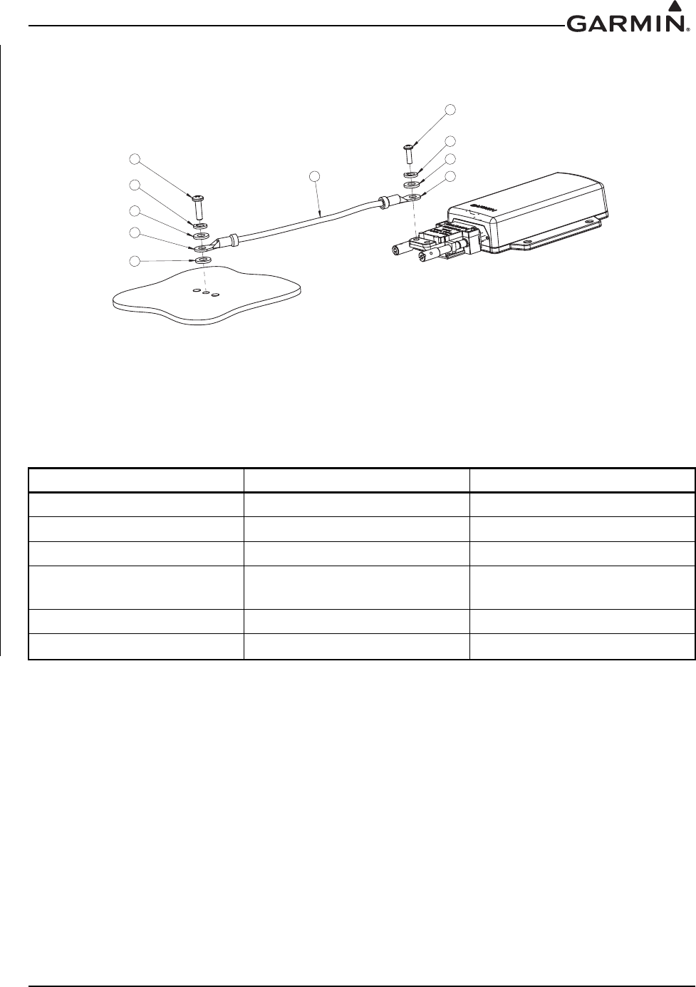
190-01007-A1 System Maintenance Manual GTN 6XX/7XX Part 23 AML STC
Rev. 7 Page 6-28
In the event of a bonding test failure, remove the bonding strap from the aircraft ground point and clean the
attachment point with a bonding brush. Re-install the bonding strap and perform the electrical bonding test
in accordance with Section 4.5 again.
Figure 6-15. Flight Stream Bonding
Table 6-8. Flight Stream Bonding Hardware
See Figure 6-15 Hardware P/N
1Screw AN515, AN515B, or AN515C
2Lock washer MS35338-137
3Flat washer NAS1149CN832R or AN960C-8
4Terminal Lugs (7 AWG or 10 AWG
depending on size of braid) MS25036
5Screw MS51957-42
6Braid QQB575R36T0250
3
31
2
4
5
2
46
3

190-01007-A1 System Maintenance Manual GTN 6XX/7XX Part 23 AML STC
Rev. 7 Page 7-1
7 EQUIPMENT CONFIGURATION AND TESTING
This section provides procedures to be followed after an LRU is replaced. At the beginning of each LRU
section, instructions are given to guide the technician for various removal and replacement scenarios.
These instructions define necessary procedures to be followed for situations in which original equipment
was reinstalled as well as for situations in which new equipment (new serial number) is installed.
7.1 GTN 6XX/7XX
Original GTN 6XX/7XX Reinstalled
If the removed GTN is installed in its original position, no software loading or configuration setting
changes are required. This does not include units that were returned for repair as their software and
configuration files are deleted during the repair testing progress. It is recommended to perform the
connector engagement check to ensure that the GTN is properly seated to the connectors.
See Section 7.1.2.1.
New, Repaired, or Exchanged GTN Installed
If a new, repaired, or exchanged GTN is installed, the correct software must be loaded to the unit. Some
configuration files must be set. See the summary in Table 7.1. Any enabled features such as TAWS-B or
ChartView will not need to be re-enabled if the configuration module was left in the aircraft.
This section covers the necessary steps to configure and test a replacement GTN unit. The steps provided
in this section are only applicable for replacement of an equivalent GTN unit (i.e. 750 for 750, 625 for 625
etc.). If wiring updates are needed or the configuration module is being replaced simultaneously, refer to
the GTN 6XX/7XX AML STC Installation Manual P/N 190-01007-A3 for installation instructions.

190-01007-A1 System Maintenance Manual GTN 6XX/7XX Part 23 AML STC
Rev. 7 Page 7-2
Table 7-1. Configuration and Checkout Procedures
Modification Required Action Affected Models
Replacing GTN with equivalent
unit
Repeat configuration steps
described in Section 7.1.1.1
(COM Configuration).
Repeat configuration steps
described in Section 7.4.1.1.2
(VOR/LOC/GS Configuration)
and Section 7.4.2.1 (Serial
Tuned DME Configuration).
Perform ground checks per
Section 7.1.2 (GTN Ground
Checks), Section 7.4.1.2.2
(VOR/ILS/GS Indicator) and
Section 7.4.2.2 (Interface
Check).
Ensure that the Basemap,
Navigation, SafeTaxi, and
Obstacle databases are up to
date per Section 3.5 and insert
SD card from previous GTN into
the replacement unit.
GTN 6XX/7XX
Replacing Configuration module
with new module
Database cards need to be
recreated when updating the
configuration module. See
Section 3.5 for instructions
regarding database updates.
GTN 6XX/7XX
Replacing Navigation Indicator
Repeat calibration per section
Section 7.4.1.1.1.1 (OBS
Resolver Calibration) (if using
GPS) or Section 7.4.1.1.2.1
(Calibrate Resolver) if using
VOR/LOC/GS receiver.
GTN 6XX/7XX
Replacing GMA 35
Refer to Section 7.2.1 for
configuration steps.
Perform checkout procedures
per Section 7.2.2.
GMA 35
Replacing a Serial Tuned DME
Perform interface check per
Section 7.4.2.2 (Interface
Check).
GTN 650/750
Replacing a Display
Perform the appropriate
interface check per Section
7.4.3 (Displays).
GTN 6XX/7XX

190-01007-A1 System Maintenance Manual GTN 6XX/7XX Part 23 AML STC
Rev. 7 Page 7-3
Replacing a Transponder
Configure remote transponder
per Section 7.4.4.1 (Remote
Transponder Configuration).
Perform interface check per
Section 7.4.2.2 (Interface
Check).
GTN 6XX/7XX
Replacing altitude encoders, air
data computers or fuel-air data
computers
No action required. GTN 6XX/7XX
Replace traffic system or
weather system
Perform the appropriate
interface check per Section
7.4.5.
GTN 6XX/7XX
Replace weather radar
Perform the appropriate
interface check per Section
7.4.6.
GTN 725/750
Replace Fan
Perform the fan interface check
per Section 7.4.8 (Fan Interface
Check).
GTN 6XX/7XX
Replace a Flight Stream 210
No configuration/interface
checkout procedures are
required to return to service.
Flight Stream 210
Modification Required Action Affected Models

190-01007-A1 System Maintenance Manual GTN 6XX/7XX Part 23 AML STC
Rev. 7 Page 7-4
7.1.1 GTN Configuration Steps
7.1.1.1 COM Configuration Page (GTN 635/650/750 Only)
Select the COM Configuration page from the GTN Setup page. These values are set at the factory and
rarely require calibration.
To enable or disable the COM radio, touch the COM key to toggle between enabled and disabled. The
COM radio defaults to the enabled state.
Review the COM configuration settings on the GTN and compare them against the GTN Configuration
and Checkout Log. A copy of the GTN Configuration and Checkout Log form may be found in the
appendices of this document. If any of the settings differ from the checkout log, update the settings to the
correct value. For information regarding individual settings, refer to the GTN 6XX/7XX AML STC
Installation Manual.
7.1.1.2 Enabled Features
Refer to Section 7.5 for instructions on feature enablement. If the configuration module is not replaced, the
enabled features will be retained upon replacing the GTN.
7.1.2 GTN Ground Checks
Ground checks of the GTN require the GTN to be powered up in configuration mode as described in
Section 3.4.
7.1.2.1 Connector Engagement Check
Prior to configuration and checkout of the GTN, the connector engagement should be checked as described
below:
1. Ensure that the GTN GPS/NAV and COM circuit breakers are pulled.
2. Slide the GTN straight into the rack until it stops about 1" short of the fully seated position.
3. Insert a 3/32" hex drive into the unit retention mechanism access hole at the bottom of the unit face
and turn the tool clockwise while pressing the bezel until the unit is firmly seated in the rack.
4. With the GTN seated, reapply power by closing the circuit breakers and turning on the avionics
master switch (if installed).
5. Again, insert the hex drive into the unit retention mechanism access hole. Turn the tool counter-
clockwise to back out the retention mechanism. Ensure that three (3) complete revolutions of the
Allen screw can be performed without red ‘X’ indication or loss of power to the GTN.
NOTE
If power is lost or the red ‘X’ condition occurs with fewer than three (3) turns, ensure there
are no obstructions to the unit fully seating in the rack. Also, the mounting rack may need
to be moved aft (toward the pilot) such that the aircraft panel does not obstruct the unit
from properly engaging in the rack.
6. Pull the circuit breakers to remove power from the unit and re-seat the GTN per step 3. Close the
breakers to restore power to the unit.

190-01007-A1 System Maintenance Manual GTN 6XX/7XX Part 23 AML STC
Rev. 7 Page 7-5
7.1.2.2 Signal Acquisition Check
NOTE
All other avionics should be turned off at the start of this test, with the GTN powered on in
normal mode. After reinstallation, the initial acquisition of position can take up to 20
minutes. Subsequent acquisitions will not take as long.
NOTE
For best results, this check should be performed outdoors away from large buildings or
objects that could obstruct the GPS antenna.
Ensure the GTN is able to acquire sufficient satellites to compute a GPS position. From the Home page,
touch the System key and then touch the GPS Status key. Under “GPS Solution”, ensure that a 3D Fix or
3D Diff Fix is obtained. If the unit is unable to acquire satellites, move the aircraft away from obstructions
which might be shading GPS reception. If the GPS solution does not improve, check the GPS antenna
installation.
Once GPS position information is available, verify that the LAT/LON agree with a known reference
position.
7.1.2.3 Receiver/Transmitter Operation (GTN 635/650/750 Only)
Tune the unit to a local VHF frequency and verify the receiver output produces a clear and understandable
audio output. Verify the transmitter functions properly by contacting another station and getting a report of
reliable communications.
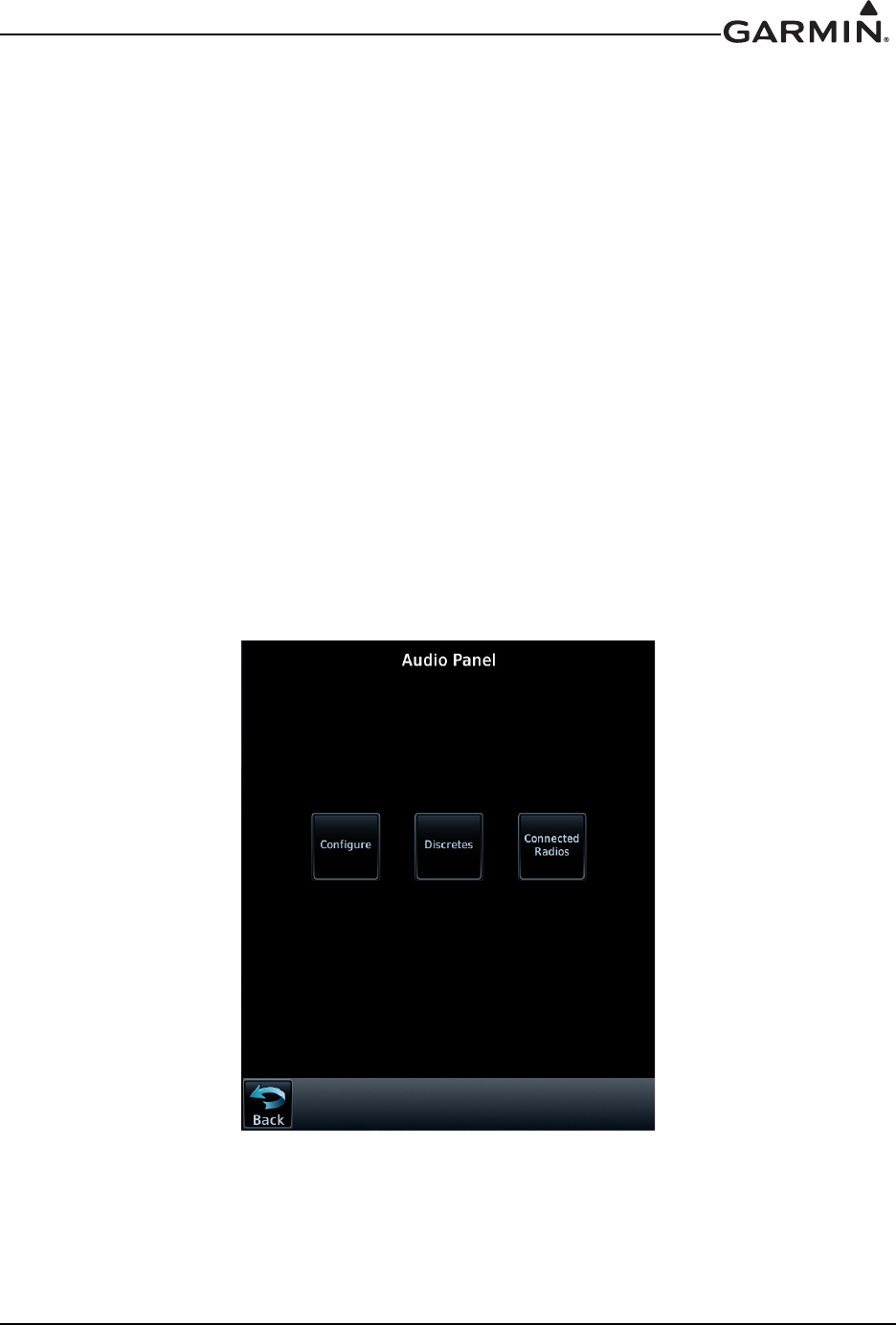
190-01007-A1 System Maintenance Manual GTN 6XX/7XX Part 23 AML STC
Rev. 7 Page 7-6
7.2 GMA 35
The following steps must be performed when replacing a GMA 35 audio panel.
1. Configure audio panel per Section 7.2.1.
2. Perform ground check per Section 7.2.2.
7.2.1 GMA 35 Audio Panel Configuration (GTN 7XX Only)
7.2.1.1 GMA 35 Audio Panel Settings
In configuration mode, touch the External Systems key (See Figure 3-8) followed by the Audio Panel
key. The Audio Panel page (Figure 7-1) will be displayed. Touch the Configure key to access
configuration settings for audio routing, volume, and miscellaneous options. See Figure 7-1. Touch Back
to return to the Audio Panel page.
Touch the Connected Radios key to set the status (Present or Not Present) of COM 2, COM 3, NAV 1,
NAV 2, RCVR 3, RCVR 4, RCVR 5, TEL, Music 1, Music 2 and Marker Beacon. Touch Back to return to
the Audio Panel page.
Review the GMA 35 audio panel configuration settings on the GTN and compare them against the GTN
Configuration Log. A copy of the GTN Configuration Log form may be found in the appendices of this
document. If any of the settings differ from the checkout log, update the settings to the correct value. For
information regarding individual settings, refer to the GTN 6XX/7XX AML STC Installation Manual.
Figure 7-1. Audio Panel Page

190-01007-A1 System Maintenance Manual GTN 6XX/7XX Part 23 AML STC
Rev. 7 Page 7-7
7.2.2 GMA 35 Audio Panel Checkout (GTN 7XX Only)
7.2.2.1 GMA 35 Interface Check (GTN 7XX Only)
1. With the GTN running and the GMA 35 audio panel powered on, go to the Home page and touch
the Audio Panel key.
2. Ensure that a red “X” is not displayed over the Audio Panel key.
After configuring the audio panel, an in-aircraft checkout may be performed with a good microphone,
headset, speaker, and avionics receivers. For testing the marker beacon, use a ramp tester that transmits a
75 MHz marker beacon test signal.
For instructions on how to operate the GMA 35 in normal mode during checkout procedures, refer to the
GTN 725/750 GMA 35 Pilot’s Guide, P/N 190-01007-03.
NOTE
In the following procedural steps allow for variation in the configuration settings for the
particular installation under test.
7.2.2.2 Failsafe Operation Check
1. Power the GMA 35 off by pulling the audio panel circuit breaker.
2. Check the failsafe operation by exercising the COM1 microphone, microphone key and audio over
the pilot’s headphones.
NOTE
Use of a true mono headset is required for this test to ensure proper wiring even if a stereo
jack is provided in the installation. Wiring left channel (tip contact) and right channel
(ring contact) backwards will cause failsafe mode not to function with mono headsets. Use
of a true mono headset is required for this test (not a stereo headset with a mono/stereo
switch because headset manufactures differ on how they accomplish this switching). This
will guarantee the condition of the right channel (ring terminal) being shorted to the
return (sleeve terminal) by the mono headset’s plug. During power-on operation, this
short will not damage the audio panel.
3. Verify that COM1 can key and transmit the pilot’s mic audio by verifying received sidetone or
checking reception of the transmission with another radio tuned to receive this transmission (verify
Pilot PTT and mic operation is delivered to this transceiver).
4. Turn the unit back on to continue testing.
NOTE
If the configuration setting “COM 1 is connected as COM 2” is set to True, then the
COM 2 microphone should be exercised rather than COM 1.

190-01007-A1 System Maintenance Manual GTN 6XX/7XX Part 23 AML STC
Rev. 7 Page 7-8
7.2.2.3 COM Transceiver Operational Check
1. Connect a headset to the pilot’s headset output and mic input jack.
2. Verify that each installed transceiver (COM) can be heard when selected.
NOTE
Depending on configuration settings, the mic selected COM may mute audio from other
COMs.
3. Verify that each installed transceiver keys for transmission and transmits clear audio from the
pilot’s mic when selected for transmission and the Pilot PTT key is pressed. (Because the audio
panel can be configured to simulate received sidetone internally, verifying transmission with a
separate radio not in the system is recommended.)
NOTE
Depending on configuration settings, other transceivers may be muted during transmit.
Also, the audio panel may mute the speaker during PTT.
4. Move the headset to the copilot’s headset jacks and verify that any one of the installed transceivers
(testing each is not necessary) receives and transmits copilot mic properly as above.
7.2.2.4 NAV Audio Check
Ensure the GMA 35 and each installed NAV receiver is powered on.
1. Tune the NAV receiver to a local VOR station.
2. Ensure the Morse code identifier is being received over the crew headsets.
3. If the audio is not heard, verify the wiring to the audio panel.
4. Ensure the audio volume is sufficient for all anticipated cockpit noise conditions.
Repeat steps 1 through 4 for each installed NAV receiver.
7.2.2.5 Alert Audio Check
If there is an alert audio source connected to the GMA 35, the interface should be verified as described
below.
1. Cause the alert audio source to produce audio. (e.g., if a traffic system is installed, command the
traffic system into self-test mode; if a TAWS system is installed, command the TAWS system into
self-test mode.)
2. Verify that the alert audio source is heard in the pilot and copilot headsets and that the audio
volume is sufficient for all anticipated cockpit noise conditions. Adjust the audio volume level as
needed. For modification of configuration settings, refer to the GTN 6XX/7XX AML STC
Installation Manual.
3. If the alert audio source is not heard in the crew headsets, check the wiring from the source to the
GMA 35 alert audio inputs.
Repeat steps 1 through 3 for each alert audio source connected to the GMA 35.

190-01007-A1 System Maintenance Manual GTN 6XX/7XX Part 23 AML STC
Rev. 7 Page 7-9
7.2.2.6 Receiver Audio Check
If there are receiver audio sources connected to the GMA 35, the interface should be verified as described
below. Ensure the GMA 35 as well as each interfaced receiver (DME, ADF, etc) is powered on.
1. Plug in a headset at pilot and copilot position.
2. Tune the installed receiver to a valid station.
3. Ensure audio is being received over the crew headsets.
4. Ensure the audio volume is sufficient for all anticipated cockpit noise conditions. Adjust the audio
output level as needed at the receiver.
Repeat steps 2 through 4 for each installed receiver.
7.2.2.7 Intercom System (ICS) Check
NOTE
If a monaural headset is plugged into any stereo phone jack position, no damage will
occur to the GMA 35. In the case of plugging a monaural headset into any passenger
position, any stereo listener will lose one channel when another passenger plugs in a
monaural headset.
1. Place the audio panel into ALL ICS mode (refer to the GTN 725/750 Pilot’s Guide, P/N 190-
01007-03) so that all ICS positions hear all others.
2. Deselect or turn off other audio sources (MKR, transceivers, receivers, alerts). Some
configurations may mute passenger intercom audio to crew when aircraft audio is present.
3. From the pilot headset position, verify the pilot, copilot, and all passenger mic inputs can be heard
in the pilot’s headset when speaking into the mic input under test (adjust pilot ICS volume if
necessary).
4. Speak into the pilot’s mic and verify that pilot mic audio is heard in the copilot headset (adjust
copilot ICS volume if necessary) and in each passenger headset (adjust passenger ICS volume if
necessary).
7.2.2.8 Music System Check (if installed)
1. Set the intercom to the ALL mode.
2. Connect a stereo audio source to MUSIC 1 or MUSIC 2. Verify that stereo audio is heard over the
Pilot headset position.
3. Tune a station on COM 1 and verify that the sound is muted by active COM 1 audio (break squelch
on COM 1 if necessary).
4. Verify that stereo audio is also heard in the passenger headsets.

190-01007-A1 System Maintenance Manual GTN 6XX/7XX Part 23 AML STC
Rev. 7 Page 7-10
7.3 Configuration Module
Upon replacing a configuration module with a new configuration module unit, no further action is required
to use the updated configuration module. Installation of a used configuration module is not recommended.
7.4 Interfaced Equipment
This manual does not cover the removal/replacement of the following interfaced equipment. However, the
following procedures are required to ensure proper functionality with the interfaced equipment. Perform
the following calibration procedures and interface checks after reinstalling or replacing any of the
optionally interfaced equipment.
7.4.1 Navigation Indicator
1. Perform calibration per Section 7.4.1.1.1.1 (if using GPS) or Section 7.4.1.1.2.1 (650/750 only) if
using VOR/LOC/GS receiver.
2. Perform ground checks per Section 7.4.1.2 and the appropriate interface check.
7.4.1.1 Navigation Indicator Calibration
7.4.1.1.1 Main Indicator (Analog) Configuration Page
Select the Main Indicator (Analog) Configuration Page, shown in Figure 7-2, from the GTN Setup page.
This page allows you to calibrate the OBS resolver, configure the CDI key, selected course for GPS and
VLOC, as well as the V-Flag state. Configurable fields are described in the following sections.
Figure 7-2. Main Indicator (Analog) Configuration Page
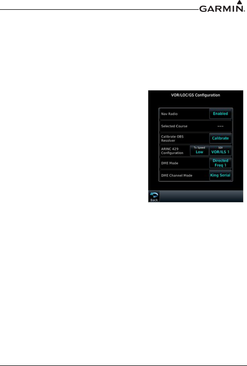
190-01007-A1 System Maintenance Manual GTN 6XX/7XX Part 23 AML STC
Rev. 7 Page 7-11
7.4.1.1.1.1 Main Indicator OBS Resolver Calibration
To calibrate the OBS resolver, touch the Calibrate key from the Main Indicator Configuration page. Next,
select 150˚ on the External CDI/HSI then touch the OK key, as prompted on the display. After the OBS
resolver is finished calibrating, the GTN will display “OBS Resolver Calibration Complete!” Touch OK
after the calibration is complete. Verify OBS operation by checking that the selected course displayed at
the top of the page is within 2° of the selected course.
The Main Indicator (Analog) Configuration page allows the CDI connected to the NAV board (P1001) to
be ground checked and allows the NAV indicator interface to be verified. See Section 7.4.1.2.1 for the
ground check.
7.4.1.1.2 VOR/LOC/GS Configuration Page
(GTN 650/750 Only)
Select the VOR/LOC/GS key on the GTN Setup page. This
page allows you to verify the CDI outputs from the
VOR/LOC/GS receiver as well as the OBS resolver input to
the VOR receiver. It also allows you to select the format for
the DME tuning data.
7.4.1.1.2.1 Calibrate OBS Resolver
To calibrate the OBS resolver, touch the Calibrate key from
the VOR/LOC/GS Configuration page. Next, select 150˚ on
the external CDI/HSI, then touch the OK key when
prompted by the display. Touch OK after calibration is
complete. Verify OBS operation by checking that the
selected course displayed at the top of the page is within 2°
of the selected course.
Figure 7-3. VOR/LOC/GS
Configuration Page

190-01007-A1 System Maintenance Manual GTN 6XX/7XX Part 23 AML STC
Rev. 7 Page 7-12
7.4.1.2 Navigation Indicator Ground Checks (Configuration Mode)
7.4.1.2.1 Main Indicator Check (Analog Only)
NOTE
If the GTN is interfaced to an electronic HSI/EFIS and the main indicator analog output is
not used, this check is not required.
NOTE
To verify if the indicator is interfaced with the GTN on the main connector (P1001),
examine the response of the indicator during the GTN self test upon power-up. If the
indicator responds according to the values described on the screen, then it is connected to
the main connector.
If the GTN is interfaced to an analog indicator on the main connector (P1001), perform the following steps
in configuration mode (Section 3.4):
1. From the configuration mode page (Figure 3-8), touch GTN Diagnostics key.
2. Touch the Main Indicator (Analog) key.
3. Verify correct operation of the lateral deviation, flag and TO/FROM flag using the corresponding
selections.
4. Verify correct operation of the vertical deviation and flag using the corresponding selections.
5. Verify correct operation of the OBS knob using the OBS Resolver Setting display. At 30°
increments around the OBS card, ensure that the indicated value is within 2° of the value set on the
indicator. If the resolver is not within 2°, calibrate the resolver as described in Section 7.4.1.1.1.1.
7.4.1.2.2 VOR/LOC/GS Indicator
If the GTN is interfaced to an analog indicator on the VOR/ILS connector (P1004), perform the following
steps:
1. From the configuration mode page (Figure 3-8), touch GTN Diagnostics key.
2. Touch the VOR/ILS Indicator (Analog) key.
3. Verify correct operation of the lateral deviation, flag and TO/FROM flag using the corresponding
selections.
4. Verify correct operation of the vertical deviation and flag using the corresponding selections.
5. Verify correct operation of the OBS knob using the Selected Course display. At 30° increments
around the OBS card, ensure that the indicated value is within 2° of the value set on the indicator.
If the resolver is not within 2°, calibrate the resolver as described in Section 7.4.1.1.2.1.

190-01007-A1 System Maintenance Manual GTN 6XX/7XX Part 23 AML STC
Rev. 7 Page 7-13
7.4.2 Serial Tuned DME
7.4.2.1 Serial Tuned DME Configuration
Under the VOR/LOC/GS configuration page, set the DME mode and DME Channel Mode to the values
specified in the Configuration Checkout Log. Configuration of these settings is required if exchanging
GTN 650/750 units, but is not required if replacing a DME with an equivalent unit.
7.4.2.2 Interface Check (650/750 Only)
Verify the interface performing the following steps:
1. Select a VOR/ILS channel that corresponds to (1) a DME station within a 40 nautical mile range,
or (2) the frequency of a DME ground tester.
2. Verify that the DME locks on to the signal and a valid distance is displayed.
3. Tune an invalid VOR station. Verify that the DME data is flagged.
4. If multiple GTNs are set up to remotely channel a DME, repeat steps 1-3 using the other GTN.
7.4.3 Displays
Perform the appropriate interface check for the replaced EHSI, EFIS, PFD, or MFD. No additional
configuration on the GTN is required when replacing a display with an equivalent unit.
7.4.3.1 Honeywell (Bendix/King) EFS 40/50 Interface Check
If a Honeywell EFS 40/50 has been connected to the GTN, the interface should be verified as described in
this section.
1. Cycle power to the first GTN and acknowledge the prompts until it gets to the Instrument Panel
Self-Test page (see Section 6.1.1)
2. Ensure that GPS1 data is displayed by pressing the 1-2 key on the EFS 40/50 control panel.
3. While the GTN is displaying the Instrument Panel Self-Test page, verify that the EFS 40/50 is
displaying data from the GPS source.
Course Deviation: Half-scale left deviation, TO indication, flag pulled
Active Waypoint: GARMN
Vertical Deviation: Half-scale up deviation (only if installation is setup to display GPS vertical
deviation)
4. On the GTN verify that an OBS value is displayed (and not dashed out).
5. Using a VOR test set verify that the CDI deviation on the EFS 40/50 is displayed correctly.
6. Cycle power to the second GTN and acknowledge the prompts until it gets to the Instrument Panel
Self-Test page.
7. If a second GTN is installed, switch to GPS2 data by pressing the 1-2 key on the EFS 40/50 control
panel and repeat steps 3 through 5 with the second GTN.

190-01007-A1 System Maintenance Manual GTN 6XX/7XX Part 23 AML STC
Rev. 7 Page 7-14
7.4.3.2 Sandel SN3308 Interface Check
If a Sandel EHSI has been connected to the GTN, the interface should be verified as described in one of the
following sections, as appropriate for the installation.
7.4.3.2.1 One GTN/One SN3308
1. Cycle power to the GTN and acknowledge the prompts until it gets to the Instrument Panel Self-
Test page (see Section 6.1.1).
2. Ensure that the SN3308 is receiving valid heading.
NOTE
The Vertical Deviation Indication will not be displayed unless the SN3308 is receiving
valid heading.
3. While the GTN is displaying the Instrument Panel Self-Test page, verify that the SN3308 is
displaying the following data from the GPS source.
Course Deviation: Half-scale left deviation, TO indication, flag pulled
Vertical Deviation: Half-scale up deviation, flag pulled
Active Waypoint: GARMN
4. On the GTN verify that an OBS value is displayed (and not dashed out).
5. Acknowledge the self-test on the GTN by touching the Continue key.
6. Select VLOC on the GTN and verify that the SN3308 displays NAV 1 or NAV 2 (depending on the
GTN navigation source configuration).
7. Using a VOR test set verify that the CDI deviation on the SN3308 is displayed correctly.

190-01007-A1 System Maintenance Manual GTN 6XX/7XX Part 23 AML STC
Rev. 7 Page 7-15
7.4.3.2.2 Two GTNs/One SN3308
1. Remove power from GTN #2 by opening up the circuit breaker.
2. Cycle power to GTN #1 and acknowledge the prompts until it gets to the Instrument Panel Self-
Test page (see Section 6.1.1).
3. Select GPS1 as the navigation source by pressing the NAV key on the SN3308. Verify that GPS1 is
displayed on the SN3308.
4. Ensure that the SN3308 is receiving valid heading. The Vertical Deviation Indication will not be
displayed unless the SN3308 is receiving valid heading.
5. While GTN #1 is displaying the Instrument Panel Self-Test page, verify that the SN3308 is
displaying the following data from GPS1.
Course Deviation: Half-scale left deviation, TO indication, flag pulled
Vertical Deviation: Half-scale up deviation, flag pulled
Active Waypoint: GARMN
6. On GTN #1 verify that an OBS value is displayed (and not dashed out).
7. Acknowledge the self test on GTN #1 by touching the Continue key.
8. Select VLOC on GTN #1 and verify that the SN3308 displays NAV 1 or NAV 2 (depending on
which navigation source the GTN is).
9. Using a VOR test set verify that the CDI deviation on the SN3308 is displayed correctly.
10. Remove power from GTN #1 and apply power to GTN #2. Acknowledge the prompts until the
Instrument Panel Self-Test page is displayed. See Section 6.1.1. Select GPS2 by pressing the NAV
key on the SN3308.
Repeat steps 5 through 9 with the second GTN.

190-01007-A1 System Maintenance Manual GTN 6XX/7XX Part 23 AML STC
Rev. 7 Page 7-16
7.4.3.2.3 Two GTNs/Two SN3308s
1. Remove power from GTN #2.
2. Cycle power to GTN #1 and acknowledge the prompts until it gets to the Instrument Panel Self-
Test page (see Section 6.1.1). Select GPS1 as the navigation source by pressing the NAV key on
the SN3308 #1. Verify that GPS1 is displayed on the SN3308.
3. Ensure that the SN3308 is receiving valid heading. The Vertical Deviation Indication will not be
displayed unless the SN3308 is receiving valid heading.
4. While GTN #1 is displaying the Instrument Panel Self-Test page, verify that the SN3308 is
displaying the following data from GPS1.
Course Deviation: Half-scale left deviation, TO indication, flag pulled
Vertical Deviation: Half-scale up deviation, flag pulled
Active Waypoint: GARMN
5. On GTN #1 verify that an OBS value is displayed (and not dashed out).
6. Acknowledge the self test on GTN #1 by touching the Continue key.
7. Select VLOC on GTN #1 and verify that the SN3308 displays NAV 1 or NAV 2 (depending on
which navigation source the GTN is).
8. Using a VOR test set verify that the CDI deviation on the SN3308 is displayed correctly.
9. Remove power from GTN #1 and apply power to GTN #2. Acknowledge the prompts until the
Instrument Panel Self-Test page is displayed (see Section 6.1.1).
10. Select GPS2 by pressing the NAV key on the SN3308.
Repeat steps 4 through 8 with the second GTN.
Perform the same procedure for the second SN3308. Ensure that SN3308 #2 is receiving valid heading by
ensuring the vertical deviation indication is being displayed.
7.4.3.3 Sandel SN3500/4500 Interface Check
If a Sandel SN3500/4500 EHSI has been connected to the GTN, the interface should be verified as
described in this section.
1. Cycle power to the GTN and acknowledge the prompts until it gets to the Instrument Panel Self-
Test page (see Section 6.1.1).
2. Ensure that the SN3500/4500 is receiving valid heading. The Vertical Deviation Indication will not
be displayed unless the SN3500/4500 is receiving valid heading.
3. While the GTN is displaying the Instrument Panel Self-Test page, verify that the SN3500/4500 is
displaying data from the GPS source.
Course Deviation: Half-scale left deviation, TO indication, flag pulled
Vertical Deviation: Half-scale up deviation, flag pulled
Active Waypoint: GARMN
4. On the GTN verify that an OBS value is displayed (and not dashed out).
5. Acknowledge the self test on the GTN by touching the Continue key.
6. Select VLOC on the GTN and verify that the SN3500/4500 displays NAV 1 or NAV 2 (depending
on which navigation source the GTN is).
7. Ensure that the NAV1 (or NAV2) indication does not have a red line through it.
Repeat steps 3 through 7 for the second GTN, if installed.

190-01007-A1 System Maintenance Manual GTN 6XX/7XX Part 23 AML STC
Rev. 7 Page 7-17
7.4.3.4 EHSI Deviation Scaling for HSI/CDI Driven by GTN through ARINC 429 Data
If the GTN has a serial connection to an EFIS display, proper scaling of the EFIS CDI and VDI must be
verified.
1. Cycle power to the GTN and acknowledge the prompts until it gets to the Instrument Panel Self-
Test page (see Section 6.1.1).
2. With the Instrument Panel Self-Test page displayed on the GTN, look on the EHSI/EFIS and
verify that the lateral deviation is half-scale left and not flagged.
3. With the Instrument Panel Self-Test page displayed on the GTN, look on the EHSI/EFIS and
verify that the vertical deviation is half-scale up and not flagged. .
7.4.3.5 GMX200/MX20 Interface Check
The Garmin GMX 200 or MX20 interface should be verified as described in this section.
1. Ensure that the GTN has a 3-D position fix.
2. Create and activate a flight plan on the GTN by touching the Direct-To key and entering a
waypoint.
3. Verify that the RTE and POS data flags are not displayed on the GMX 200/MX20.
4. Verify that the flight plan is displayed on the GMX 200/MX20 using the flight plan (FPL)
function.
7.4.4 Transponder
1. For remote transponders, configure transponder per Section 7.4.4.1.
2. Perform interface check per Section 7.4.4.2.
7.4.4.1 Remote Transponder Configuration
A remote transponder can be configured by the GTN through RS-232 if a transponder is configured for one
of the RS-232 ports. To configure the transponder, it must first be selected as present and the type of
transponder installed must be specified. To do this, access the Interfaced Equipment page on the GTN
Setup page (Figure 3-11). Next, go to the External Systems page and touch the XPDR key. This displays
the page shown in Figure 7-4, which allows the remote transponder to be configured. The remote
transponder should be configured in accordance with the installation manual for that specific transponder.
NOTE
If the GTN controls any transponder (GTX 32/33/327/328/330), then that transponder will
boot into the same mode (Normal or Configuration) as the GTN.
NOTE
If the GTN is not communicating with the GTX transponder, all of the editable fields for
the setup items shown in the following sections will be dashed out. If the fields are dashed
out, check the wiring and pin connections from the GTN to the transponder.
NOTE
The GTN can interface to the GTX 327/328/330/330 ES; however, configuration of the
panel-mounted GTX 327/328/330/330 ES is not supported. These transponders should be
configured per their installation manuals rather than through the GTN.
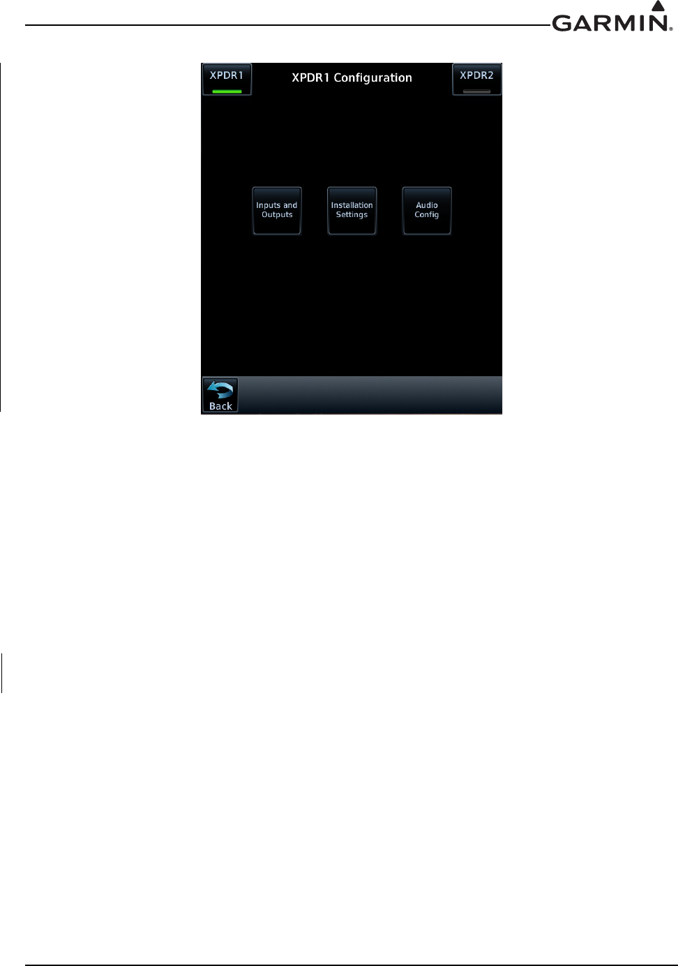
190-01007-A1 System Maintenance Manual GTN 6XX/7XX Part 23 AML STC
Rev. 7 Page 7-18
Figure 7-4. XPDR1 Configuration Page
7.4.4.2 Transponder Interface Check
If the GTN is interfaced to a GTX 32/33 remote transponder or a GTX 327/328/330 configured as a remote
transponder, the following checks must be completed.
1. With the GTN unit running in normal mode and the transponder powered on, go to the Home page
and ensure there is no red ‘X’ over the transponder data field on the screen.
2. Check that a code can be entered into the code field. Enter a code using the keypad and then touch
the Enter key. Check the code that was entered is displayed in the transponder data field.
3. If dual transponders are installed, select Transponder 2 and perform steps 1 and 2 for the second
transponder as well.
4. To verify wiring is not crossed, pull the Transponder 1 circuit breaker and check the Transponder 1
data field is red ‘X’d.
5. Repeat the steps 1 through 3 for the second GTN.

190-01007-A1 System Maintenance Manual GTN 6XX/7XX Part 23 AML STC
Rev. 7 Page 7-19
7.4.5 Traffic or Weather System
Perform the appropriate interface check for the traffic or weather system. No additional GTN configuration
steps are required for replacing a traffic or weather device with an equivalent unit.
7.4.5.1 Ryan TCAD Traffic System Interface Check
If a Ryan TCAD has been connected to the GTN 6XX/7XX unit, the traffic interface should be verified as
described in this section.
1. Go the Traffic page on the GTN from the HOME page group.
2. Verify that NO DATA is not displayed in yellow on the center of the traffic page.
3. Using the SHIELD SETUP under the Traffic Menu, verify that the shield mode can be changed.
7.4.5.2 ARINC 429 Traffic System Interface Check
If a Garmin GTS 8XX Traffic system, L-3 Communications SKY497/SKY899 SkyWatch® sensor or a
Honeywell (Bendix/King) KTA 810 TAS/KMH 820 IHAS has been connected to the GTN through
ARINC 429, the traffic interface should be verified as described in this section.
1. Go to the Traffic page on the GTN from the home page.
2. Verify that NO DATA is not displayed in yellow on the center of the traffic page.
3. If the GTN is configured to control the traffic system. Verify that the traffic system mode can be
changed from STBY to OPER.
4. Switch the traffic system mode to STBY, and then run the traffic self test from the Menu.
5. Verify that the traffic system executes a self test and that a self-test pattern is displayed on the GTN
traffic display.
6. Restart the GTN in Configuration Mode.
7. On the Traffic page in the External Systems page group, verify that there is data displayed in the
Altitude field.
7.4.5.3 Stormscope® Interface Check
If an L-3 Communications WX-500 Stormscope has been connected to the GTN, the Stormscope interface
should be verified as described in this section.
1. Go to the Lightning page on the GTN.
2. Verify that ‘STORMSCOPE FAILED’ is not displayed in yellow on the center of the Lightning
page.
3. Verify that the Stormscope mode can be changed from Strike to Cell, and vice versa.
7.4.5.4 TIS (Garmin GTX 33/330) Interface Check
If a Garmin GTX 33/330 transponder has been connected to the GTN as a TIS traffic source, the traffic
interface should be verified as described in this section.
1. Select the Traffic Map from the GTN Home page.
2. Verify that TIS FAIL is not displayed in the upper left corner under Traffic Status, and that NO
DATA (yellow) is not displayed over the ownship symbol.
3. On the upper left corner of the Traffic Map page, verify that the status of the traffic system is either
TIS Standby or TIS Operating/Unavailable (i.e. TAS should not be displayed).

190-01007-A1 System Maintenance Manual GTN 6XX/7XX Part 23 AML STC
Rev. 7 Page 7-20
The following additional steps should only be completed if the GTN is controlling the traffic system.
1. Pull the transponder circuit breaker and verify the air data fields are red ‘X’d.
2. If a squat switch (or airspeed switch) is connected to the GTX 33/330, ensure that it is in AIR
mode.
3. Alternately touch the Standby key and Operate key to change the mode of the traffic system. It
may take several seconds for the traffic system to change modes.
4. Verify that the mode of the traffic system can be changed.
7.4.6 Weather Radar
Perform the appropriate interface check for the weather radar. No additional GTN configuration steps are
required for replacing a weather radar with an equivalent unit.
7.4.6.1 GWX 68/70 Weather Radar Interface Check
This section verifies that the interface between the GTN 7XX and the GWX 68/70 weather radar is
functional.
1. Start the GTN in normal mode.
2. On the Home page, touch the Weather key and then the Radar key.
3. Touch the Mode key and select Standby mode and wait for the warm-up to complete.
4. Touch the Mode key again and select Test mode.
5. Verify that the GWX 68/70 begins sweeping and the test pattern is shown.
6. If supported by the installation, verify that stabilization is on (STAB On is displayed in the upper
right corner of the radar display).
7. Touch the Mode key, set the mode to Off.
Repeat steps 1 through 7 for the second GTN 7XX (if installed).

190-01007-A1 System Maintenance Manual GTN 6XX/7XX Part 23 AML STC
Rev. 7 Page 7-21
7.4.6.2 ARINC 708 Weather Radar Interface Check
This section verifies that the interface between the GTN 7XX and ARINC 708 weather radar is functional.
1. Start the GTN in normal mode. If there are dual GTN 7XXs, start both in normal mode.
2. On each GTN, go to the Home page, touch Weather and then Radar.
3. On one GTN, touch the Mode key and select Standby mode and wait for the warmup to complete.
4. Touch the Mode key again and select Test mode.
5. Verify that the radar begins sweeping and the test pattern is shown.
WARNING
Aircraft should be outdoors and personnel should not be in front of the weather radar
when it is radiating (i.e. when Weather or Ground mode is selected on the GTN).
6. If stabilization is supplied to the radar, turn the radar to Weather mode and turn stabilization on in
the weather menu. Verify that STAB On is displayed in the upper right corner or the radar display.
If STAB INOP is displayed, verify that stabilization is being supplied to the weather radar R/T.
7. Touch the Mode key to set the mode to Off.
NOTE
If only one GTN 7XX is installed, the following steps do not have to be carried out.
8. Repeat steps 1 through 7 for the second GTN 7XX.
9. On each GTN 7XX, touch the Mode key and select Standby and wait for the warm-up to complete.
10. On each GTN 7XX, touch the Mode key again and select Test mode.
11. On GTN #1, touch the Zoom Out key to increase the range of the radar display. Verify that the
range on GTN #1 changes and the range on GTN #2 does not change.
12. On GTN #2, touch the Zoom Out key to increase the range of the radar display – select a different
zoom level than GTN #1. Verify that the range on GTN #2 changes and the range on GTN #1 does
not change.
13. On each GTN 7XX, use the Mode key to set the mode to Off.

190-01007-A1 System Maintenance Manual GTN 6XX/7XX Part 23 AML STC
Rev. 7 Page 7-22
7.4.7 GDL 88
When testing the GDL 88, the aircraft must be located outside and have an unobstructed view of the sky. If
the GDL 88 is installed and connected to the GTN, perform the following steps. No additional
configuration steps are required when replacing the GDL 88 with an equivalent unit.
1. Start all GTNs in Configuration Mode as described in Section 3.4.
2. Touch the External Systems key.
3. Touch the GDL 88 key.
4. Touch Diagnostics and then the GPS/SBAS Data key.
5. Verify that the GDL 88 is receiving valid position source data.
6. Verify that the status of the External PPS connection(s) is valid.
7.4.8 Fan Interface Check
The fan that is mounted to the GTN backplate should be checked after replacing the fan. With the GTN
unit running in normal mode and the fan powered on and running, go to the Home page and touch the
Message Queue key. Ensure that the “COOLING FAN- the cooling fan has failed” message is not
displayed. Note that the fan may take a few minutes to power on if the unit is below normal operating
temperature.
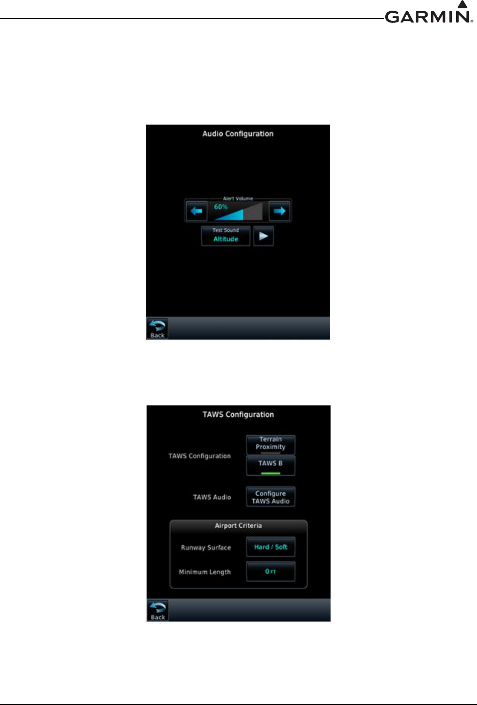
190-01007-A1 System Maintenance Manual GTN 6XX/7XX Part 23 AML STC
Rev. 7 Page 7-23
7.5 Enabled Features
See Section 3.4.4 for guidance on enabling features.
7.5.1 TAWS Configuration and Checks (For Units with TAWS Only)
Reconfigure TAWS settings per the Configuration Checkout Log. The TAWS configuration settings are
located under the GTN Options menu.
Figure 7-5. Audio Configuration Page
Figure 7-6. TAWS Configuration Page

190-01007-A1 System Maintenance Manual GTN 6XX/7XX Part 23 AML STC
Rev. 7 Page 7-24
7.5.1.1 TAWS System Check
While on the ground, turn on the GTN following normal power-up procedures. Also turn on the audio
panel.
NOTE
A 3D GPS position fix is required to conduct the check.
1. Select the Terrain page from the normal mode Home page.
2. Touch the Menu key.
3. Touch the Test TAWS key.
4. Wait until the TAWS self-test completes (10-15 seconds) to hear the TAWS system status aural
message.
The aural message “TAWS System Test OK” will be annunciated if the TAWS system is
functioning properly.
The aural message “TAWS System Failure” will be annunciated if the TAWS system is NOT
functioning properly. Also, “TAWS FAIL” will appear in amber on the screen.
If no audio message is heard, then a fault exists within the audio system or associated wiring and the
TAWS capability must be considered non-functional. Verify the TAWS audio wiring to the audio panel.

190-01007-A1 System Maintenance Manual GTN 6XX/7XX Part 23 AML STC
Rev. 7 Page 8-1
8 SYSTEM RETURN TO SERVICE PROCEDURE
8.1 Maintenance Records
After conducting required return-to-service procedures in accordance with Table 7-1 and updating aircraft
records in accordance with this section, the aircraft may be returned to service.
Record the following information in the appropriate aircraft maintenance logs:
Software versions loaded as part of any maintenance action.
Record part and serial numbers of any LRU which was replaced.
Record any database updates which were performed during maintenance.
Verify that replacement LRUs software and/or FPGA versions match those in the Configuration
Log from Appendix A, a copy of which should be in the aircraft records.
Any other applicable information related to the maintenance work performed on the aircraft.

190-01007-A1 System Maintenance Manual GTN 6XX/7XX Part 23 AML STC
Rev. 7 Page A-1
APPENDIX A AIRCRAFT SPECIFIC INFORMATION
An electronic fillable form is available. For updating from GTN v5.00 to v5.13, a separate fillable form
is available. Refer to the “Attachments” panel of this manual. Acrobat Reader 8.0 or later is necessary to
view and fill out the form. You can download Acrobat Reader by visiting www.adobe.com.

190-01007-A1 System Maintenance Manual GTN 6XX/7XX Part 23 AML STC
Rev. 7 Page A-2
$33(1',;$ $,5&5$)763(&,),&,1)250$7,21
*(1(5$/,1)250$7,21
'DWH %\
$,5&5$)7
$,5&5$)70$.(
$,5&5$)702'(/
$,5&5$)76(5,$/
$,5&5$)75(*
*71
8QLW31 0RG/HYHO
8QLW0RGHO 6HULDO
*36$QWHQQD31 *36$QWHQQD0RGHO
*71>1$@
8QLW31 0RG/HYHO
8QLW0RGHO 6HULDO
*36$QWHQQD31 *36$QWHQQD0RGHO
*0$>1$@
8QLW31 0RG/HYHO
8QLW0RGHO 6HULDO
)OLJKW6WUHDP>1$@
8QLW31 0RG/HYHO
8QLW0RGHO 6HULDO
190-01007-A1 System Maintenance Manual GTN 6XX/7XX Part 23 AML STC
Rev. 7 Page A-3
*71;;;;3$57&21),*85$7,21/2*±*71
6<67(0,1)250$7,21
*7162)7:$5(9(56,216
0DLQ%RDUG
6RIWZDUH %RRW&RGH )3*$
7RXFK&RQWUROOHU%RDUG
6RIWZDUH %RRW&RGH
*36:$$6%RDUG
6RIWZDUH
1$9%RDUG>1$@
6RIWZDUH %RRW&RGH )3*$
&20%RDUG>1$@
6RIWZDUH %RRW&RGH )3*$
*716(7830(18
$5,1&&21),*85$7,21
,Q+LJK /RZ 2XW+LJK /RZ
,Q+LJK /RZ 2XW+LJK /RZ
,Q+LJK /RZ 2XW+LJK /RZ
,Q+LJK /RZ 6',&RPPRQ /1$9/1$9
56&21),*85$7,21
,Q 2XW
,Q 2XW
,Q 2XW
,Q 2XW
,Q 2XW
,Q 2XW

190-01007-A1 System Maintenance Manual GTN 6XX/7XX Part 23 AML STC
Rev. 7 Page A-4
*71;;;;3$57&21),*85$7,21/2*±*71&217,18('
*716(7830(18&217,18('
+6'%(7+(51(7&21),*85$7,21
3RUW&RQQHFWHG 1RW&RQQHFWHG 3RUW&RQQHFWHG 1RW&RQQHFWHG
3RUW&RQQHFWHG 1RW&RQQHFWHG 3RUW&RQQHFWHG 1RW&RQQHFWHG
,17(5)$&('(48,30(17&21),*85$7,21
&URVV6LGH1DYLJDWRU3UHVHQW1RW3UHVHQW
*'/$ 3UHVHQW1RW3UHVHQW 7\SH
*'/' 3UHVHQW1RW3UHVHQW 7\SH
7UDQVSRQGHU 3UHVHQW1RW3UHVHQW 7\SH
7UDQVSRQGHU 3UHVHQW1RW3UHVHQW 7\SH
*65 3UHVHQW1RW3UHVHQW
*:; 3UHVHQW1RW3UHVHQW 7\SH
0$,1,1',&$725$1$/2*&21),*85$7,21
&',.H\(QDEOHG'LVDEOHG 1$ 6HOHFWHG&RXUVHIRU9/2&$OORZ,JQRUH 1$
6HOHFWHG&RXUVHIRU*36$OORZ,JQRUH 9)ODJ6WDWH1RUPDO'HFOXWWHU
/,*+7,1*&21),*85$7,21
,)(1+$1&('/,*+7,1*,6',6$%/('
/LJKWLQJ&RQILJXUDWLRQ>1$@
'LVSOD\6RXUFH3KRWRFHOO/LJKWLQJ%XV .H\V6RXUFH 3KRWRFHOO/LJKWLQJ%XV/LJKWLQJ%XV
'LVSOD\0LQLPXP/HYHO 'LVSOD\0LQLPXP/HYHO
&RQILJXUH3KRWRFHOO>1$@
5HVSRQVH7LPH
VHF6ORSH 2IIVHW
3KRWRFHOO2YHUULGH
.H\%DFNOLJKW&XWRII 3KRWRFHOO7UDQVLWLRQ
&RQILJXUH/LJKWLQJ%XV>1$@
/LJKWLQJ%XV 9'&9'&9'&9$&
5HVSRQVH7LPH
VHF6ORSH 2IIVHW
/LJKWLQJ%XV>1$@9'&9'&9'&9$&
5HVSRQVH7LPH
VHF6ORSH 2IIVHW
*'8 3UHVHQW1RW3UHVHQW 7\SH
3UHVHQW1RW3UHVHQW 7\SH
3UHVHQW1RW3UHVHQW 7\SH
*'8
*'8

190-01007-A1 System Maintenance Manual GTN 6XX/7XX Part 23 AML STC
Rev. 7 Page A-5
*71;;;;3$57&21),*85$7,21/2*±*71&217,18('
*716(7830(18&217,18('
(1+$1&('/,*+7,1*&21),*85$7,21
,)(1$%/('210$,16<67(0&21),*85$7,213$*(
(1+$1&('/,*+7,1*>1$@
6285&(6(77,1*6
'LVSOD\6RXUFH3KRWRFHOO/LJKWLQJ%XV.H\V6RXUFH3KRWRFHOO/LJKWLQJ%XV/LJKWLQJ%XV
3KRWRFHOO5HVSRQVH7LPH
VHF
/LJKWLQJ%XV>1$@,QSXW7\SH9'&9'&9'&9$&5HVSRQVH7LPH VHF
/LJKWLQJ%XV>1$@,QSXW7\SH9'&9'&9'&9$&5HVSRQVH7LPH VHF
'$<02'(23(5$7,21
3KRWRFHOO7UDQVLWLRQ .H\%DFNOLJKW&XWRII
',63/$<
0LQLPXP/HYHO 0D[LPXP/HYHO
&RQILJXUH&XUYH
9HUWH[,QSXW/HYHO 2XWSXW/HYHO 9HUWH[,QSXW/HYHO 2XWSXW/HYHO
9HUWH[,QSXW/HYHO 2XWSXW/HYHO9HUWH[,QSXW/HYHO 2XWSXW/HYHO
.(<6
0LQLPXP/HYHO 0D[LPXP/HYHO
&RQILJXUH&XUYH
9HUWH[,QSXW/HYHO 2XWSXW/HYHO 9HUWH[,QSXW/HYHO 2XWSXW/HYHO
9HUWH[,QSXW/HYHO 2XWSXW/HYHO 9HUWH[,QSXW/HYHO 2XWSXW/HYHO
1,*+702'(23(5$7,21>1$@
3KRWRFHOO7UDQVLWLRQ .H\%DFNOLJKW&XWRII
',63/$<
0LQLPXP/HYHO 0D[LPXP/HYHO
&RQILJXUH&XUYH
9HUWH[,QSXW/HYHO 2XWSXW/HYHO 9HUWH[,QSXW/HYHO 2XWSXW/HYHO
9HUWH[,QSXW/HYHO 2XWSXW/HYHO 9HUWH[,QSXW/HYHO 2XWSXW/HYHO
.(<6
0LQLPXP/HYHO 0D[LPXP/HYHO
&RQILJXUH&XUYH
9HUWH[,QSXW/HYHO 2XWSXW/HYHO 9HUWH[,QSXW/HYHO 2XWSXW/HYHO
9HUWH[,QSXW/HYHO 2XWSXW/HYHO 9HUWH[,QSXW/HYHO 2XWSXW/HYHO

190-01007-A1 System Maintenance Manual GTN 6XX/7XX Part 23 AML STC
Rev. 7 Page A-6
*71;;;;3$57&21),*85$7,21/2*±*71&217,18('
*716(7830(18&217,18('
$8',2&21),*85$7,21
$OHUW9ROXPH/HYHO
75$)),&&21),*85$7,21
7UDIILF,QWUXGHU6\PERO&RORU&\DQ:KLWH *71&RQWURORI7UDIILF6\VWHP<HV1R
0$,16<67(0&21),*85$7,21
$LUIUDPH7\SH)L[HG:LQJ
$LU*URXQG7KUHVKROG
.7
$LU*URXQG'LVFUHWH$FWLYHIRU$LUERUQH
+HDGLQJ6RXUFH,QSXW &RQQHFWHG1RW&RQQHFWHG
5DGLR $OWLPHWHU ,QSXW &RQQHFWHG 1RW &RQQHFWHG
5DGLR$OWLPHWHUQRWDSSURYHGXQGHUWKLV67&
$OWLWXGH6RXUFH,QSXW&RQQHFWHG1RW&RQQHFWHG
$FWLYHIRU*URXQG
(QKDQFHG/LJKWLQJ0RGH(QDEOHG'LVDEOHG
&20&21),*85$7,21*7121/<
&205DGLR(QDEOHG'LVDEOHG &205)6TXHOFK
0,&*DLQ
G% 6LGHWRQH9ROXPH G%
925/2&*6&21),*85$7,21*7121/<
1$95DGLR (QDEOHG 'LVDEOHG '0(0RGH'LUHFWHG)UHT'LUHFWHG)UHT
$5,1&7;6SHHG+LJK /RZ '0(&KDQQHO0RGH
$5,1&6', &RPPRQ925,/6 925,/6
$5,1&&21),*85$7,21
3RUW([WHUQDO:HDWKHU5DGDU2II2Q
9RLFH&RPPDQG(QDEOHG'LVDEOHG
*36$QWHQQD+HLJKW$ERYH*URXQG)79RLFH&RPPDQGQRWDSSURYHGXQGHUWKLV67&
)XHO7\SH$9*DV-HW$-HW% 3LORW3RVLWLRQ5LJKW/HIW
6\QFKUR+HDGLQJ,QSXW &RQQHFWHG1RW&RQQHFWHG&URVVILOO6WDWXV$OHUW(QDEOHG'LVDEOHG
*366HOHFW$XWR3URPSW &URVVILOO6WDWXV$OHUWQRWDSSURYHGXQGHUWKLV67&
'DWDEDVH6<1&3LORW&RQWURO(QDEOHG'LVDEOHG6\VWHP,' *71 *71

190-01007-A1 System Maintenance Manual GTN 6XX/7XX Part 23 AML STC
Rev. 7 Page A-7
*71;;;;3$57&21),*85$7,21/2*±*71&217,18('
*716(7830(18&217,18('
',6&5(7(6&21),*85$7,21
--9/2&$QQXQFLDWH
--
-
-
-
-'HPR0RGH6HOHFW
-
-
-6\QFKUR9DOLG/RZ
-
-6\QFKUR9DOLG+LJK
-
-*36$QQXQFLDWH
-
-
-
-,/6*36$SSURDFK$QQXQFLDWH
-
-
-
-
-
-
-
-
-
--
--
$YDLODEOHRQO\RQ*71DQG*71XQLWV
:$<32,176&21),*85$7,21
0DUNRQ7DUJHW(QDEOHG'LVDEOHG
2ZQVKLS&RQILJXUDWLRQ
2:16+,3&21),*85$7,21
.BSLPO5BSHFUOPUBQQSPWFEVOEFSUIJT45$
Selection of ownship color magenta is not covered under this STC.
190-01007-A1 System Maintenance Manual GTN 6XX/7XX Part 23 AML STC
Rev. 7 Page A-8
*71;;;;3$57&21),*85$7,21/2*±*71&217,18('
*71237,2160(18
7(55$,1&21),*85$7,21
7HUUDLQ0RGH7HUUDLQ3UR[LPLW\7$:6$7$:6%
7$:6$XGLR&OLSV
*6'&DXWLRQ³*OLGHVORSH´
52&&DXWLRQ³2EVWDFOH$KHDG´[
1&5&DXWLRQ³'RQ¶W6LQN´
³&DXWLRQ2EVWDFOH´[
³7RR/RZ7HUUDLQ´ ,7,&DXWLRQ ³7HUUDLQ$KHDG´[
(&5&DXWLRQ³7HUUDLQ7HUUDLQ´ ³&DXWLRQ7HUUDLQ´[
('5&DXWLRQ³6LQN5DWH´ 57&&DXWLRQ ³7HUUDLQ$KHDG´[
³&DXWLRQ7HUUDLQ´[
),7)ODS&DXWLRQ³7RR/RZ)ODSV´ ,2,:DUQLQJ ³2EVWDFOH$KHDG3XOO8S´[
³2EVWDFOH´[³3XOO8S´[
),7*HDU&DXWLRQ³7RR/RZ*HDU´ ,/,:DUQLQJ ³:LUH$KHDG3XOO8S´[
³:LUH´[³3XOO8S´[
3'$&DXWLRQ³7RR/RZ7HUUDLQ´
,7,:DUQLQJ ³7HUUDLQ$KHDG3XOO8S´[
³7HUUDLQ´[³3XOO8S´[
),76SHHG&DXWLRQ³7RR/RZ7HUUDLQ´
57&:DUQLQJ ³7HUUDLQ$KHDG3XOO8S´[
³7HUUDLQ´[³3XOO8S´[
),77DNHRII&DXWLRQ³7RR/RZ7HUUDLQ´
(&5:DUQLQJ ³7RQH7RQH3XOO8S´
,2,&DXWLRQ ³2EVWDFOH$KHDG´[
('5:DUQLQJ ³7RQH7RQH3XOO8S´
³&DXWLRQ2EVWDFOH´[
)7 ³)LYH+XQGUHG´
7$:66HWWLQJV
5XQZD\6XUIDFH $Q\ +DUG2QO\ +DUG6RIW :DWHU
)7
.7
.7
.7
$FWLYHIRU/DQGLQJ$FWLYHIRU1RQ/DQGLQJ
0LQLPXP5XQZD\/HQJWK
$SSURDFK6SHHG7$:6$2QO\
0$;)ODS([WHQVLRQ6SHHG7$:6$2QO\
0$;*HDU([WHQVLRQ6SHHG7$:6$2QO\
)ODS3RVLWLRQ'LVFUHWH7$:6$2QO\
/DQGLQJ*HDU3RVLWLRQ'LVFUHWH7$:6$2QO\ $FWLYHIRU/DQGLQJ$FWLYHIRU1RQ/DQGLQJ
,/,&DXWLRQ³:LUH$KHDG´[
³&DXWLRQ:LUH´[
5/&&DXWLRQ³:LUH$KHDG´[
³&DXWLRQ:LUH´[
5/&:DUQLQJ ³:LUH$KHDG3XOO8S´[
³:LUH´[³3XOO8S´[
52&:DUQLQJ ³2EVWDFOH$KHDG3XOO8S´[
³2EVWDFOH´[³3XOO8S´[

190-01007-A1 System Maintenance Manual GTN 6XX/7XX Part 23 AML STC
Rev. 7 Page A-9
*71;;;;3$57&21),*85$7,21/2*±*71±&217,18('
*71237,2160(18&217,18('
&+$576
&KDUWV&RQILJXUHG 1RQH )OLWH&KDUWV &KDUW9LHZ
&2075$160,732:(5
&RP7UDQVPLW3RZHU 1RUPDO : 1$
:($7+(55$'$5
'LJLWDO5DGDU 1$(QDEOHG
7XUEXOHQFH'HWHFWLRQ1$(QDEOHG
*URXQG&OXWWHU6XSSUHVVLRQ 1$(QDEOHG
127(6

190-01007-A1 System Maintenance Manual GTN 6XX/7XX Part 23 AML STC
Rev. 7 Page A-10
*71;;;;3$57&21),*85$7,21/2*±*71
6<67(0,1)250$7,21
*7162)7:$5(9(56,216
0DLQ%RDUG
6RIWZDUH %RRW&RGH )3*$
7RXFK&RQWUROOHU%RDUG
6RIWZDUH %RRW&RGH
*36:$$6%RDUG
6RIWZDUH
1$9%RDUG>1$@
6RIWZDUH %RRW&RGH )3*$
&20%RDUG>1$@
6RIWZDUH %RRW&RGH )3*$
*716(7830(18
$5,1&&21),*85$7,21
,Q+LJK /RZ 2XW+LJK /RZ
,Q+LJK /RZ 2XW+LJK /RZ
,Q+LJK /RZ 2XW+LJK /RZ
,Q+LJK /RZ 6',&RPPRQ /1$9/1$9
56&21),*85$7,21
,Q 2XW
,Q 2XW
,Q 2XW
,Q 2XW
,Q 2XW
,Q 2XW

190-01007-A1 System Maintenance Manual GTN 6XX/7XX Part 23 AML STC
Rev. 7 Page A-11
*71;;;;3$57&21),*85$7,21/2*±*71&217,18('
*716(7830(18&217,18('
+6'%(7+(51(7&21),*85$7,21
3RUW&RQQHFWHG 1RW&RQQHFWHG 3RUW&RQQHFWHG 1RW&RQQHFWHG
3RUW&RQQHFWHG 1RW&RQQHFWHG 3RUW&RQQHFWHG 1RW&RQQHFWHG
,17(5)$&('(48,30(17&21),*85$7,21
&URVV6LGH1DYLJDWRU3UHVHQW1RW3UHVHQW
*'/$ 3UHVHQW1RW3UHVHQW 7\SH
*'/' 3UHVHQW1RW3UHVHQW 7\SH
7UDQVSRQGHU 3UHVHQW1RW3UHVHQW 7\SH
7UDQVSRQGHU 3UHVHQW1RW3UHVHQW 7\SH
*65 3UHVHQW1RW3UHVHQW
*:; 3UHVHQW1RW3UHVHQW 7\SH
0$,1,1',&$725$1$/2*&21),*85$7,21
&',.H\(QDEOHG'LVDEOHG 1$ 6HOHFWHG&RXUVHIRU9/2&$OORZ,JQRUH 1$
6HOHFWHG&RXUVHIRU*36$OORZ,JQRUH 9)ODJ6WDWH1RUPDO'HFOXWWHU
/,*+7,1*&21),*85$7,21
,)(1+$1&('/,*+7,1*,6',6$%/('
/LJKWLQJ&RQILJXUDWLRQ>1$@
'LVSOD\6RXUFH3KRWRFHOO/LJKWLQJ%XV .H\V6RXUFH 3KRWRFHOO/LJKWLQJ%XV/LJKWLQJ%XV
'LVSOD\0LQLPXP/HYHO 'LVSOD\0LQLPXP/HYHO
&RQILJXUH3KRWRFHOO>1$@
5HVSRQVH7LPH
VHF6ORSH 2IIVHW
3KRWRFHOO2YHUULGH
.H\%DFNOLJKW&XWRII 3KRWRFHOO7UDQVLWLRQ
&RQILJXUH/LJKWLQJ%XV>1$@
/LJKWLQJ%XV9'&9'&9'&9$&
5HVSRQVH7LPH
VHF6ORSH 2IIVHW
/LJKWLQJ%XV>1$@9'&9'&9'&9$&
5HVSRQVH7LPH
VHF6ORSH 2IIVHW
*'8 3UHVHQW1RW3UHVHQW 7\SH
3UHVHQW1RW3UHVHQW 7\SH
3UHVHQW1RW3UHVHQW 7\SH
*'8
*'8
190-01007-A1 System Maintenance Manual GTN 6XX/7XX Part 23 AML STC
Rev. 7 Page A-12
*71;;;;3$57&21),*85$7,21/2*±*71&217,18('
*716(7830(18&217,18('
(1+$1&('/,*+7,1*&21),*85$7,21
,)(1$%/('210$,16<67(0&21),*85$7,213$*(
(1+$1&('/,*+7,1*>1$@
6285&(6(77,1*6
'LVSOD\6RXUFH3KRWRFHOO/LJKWLQJ%XV.H\V6RXUFH3KRWRFHOO/LJKWLQJ%XV/LJKWLQJ%XV
3KRWRFHOO5HVSRQVH7LPH
VHF
/LJKWLQJ%XV>1$@,QSXW7\SH9'&9'&9'&9$&5HVSRQVH7LPH VHF
/LJKWLQJ%XV>1$@,QSXW7\SH9'&9'&9'&9$&5HVSRQVH7LPH VHF
'$<02'(23(5$7,21
3KRWRFHOO7UDQVLWLRQ .H\%DFNOLJKW&XWRII
',63/$<
0LQLPXP/HYHO 0D[LPXP/HYHO
&RQILJXUH&XUYH
9HUWH[,QSXW/HYHO 2XWSXW/HYHO 9HUWH[,QSXW/HYHO 2XWSXW/HYHO
9HUWH[,QSXW/HYHO 2XWSXW/HYHO9HUWH[,QSXW/HYHO 2XWSXW/HYHO
.(<6
0LQLPXP/HYHO 0D[LPXP/HYHO
&RQILJXUH&XUYH
9HUWH[,QSXW/HYHO 2XWSXW/HYHO 9HUWH[,QSXW/HYHO 2XWSXW/HYHO
9HUWH[,QSXW/HYHO 2XWSXW/HYHO 9HUWH[,QSXW/HYHO 2XWSXW/HYHO
1,*+702'(23(5$7,21>1$@
3KRWRFHOO7UDQVLWLRQ .H\%DFNOLJKW&XWRII
',63/$<
0LQLPXP/HYHO 0D[LPXP/HYHO
&RQILJXUH&XUYH
9HUWH[,QSXW/HYHO 2XWSXW/HYHO 9HUWH[,QSXW/HYHO 2XWSXW/HYHO
9HUWH[,QSXW/HYHO 2XWSXW/HYHO 9HUWH[,QSXW/HYHO 2XWSXW/HYHO
.(<6
0LQLPXP/HYHO 0D[LPXP/HYHO
&RQILJXUH&XUYH
9HUWH[,QSXW/HYHO 2XWSXW/HYHO 9HUWH[,QSXW/HYHO 2XWSXW/HYHO
9HUWH[,QSXW/HYHO 2XWSXW/HYHO 9HUWH[,QSXW/HYHO 2XWSXW/HYHO

190-01007-A1 System Maintenance Manual GTN 6XX/7XX Part 23 AML STC
Rev. 7 Page A-13
*71;;;;3$57&21),*85$7,21/2*±*71&217,18('
*716(7830(18&217,18('
$8',2&21),*85$7,21
$OHUW9ROXPH/HYHO
75$)),&&21),*85$7,21
7UDIILF,QWUXGHU6\PERO&RORU&\DQ:KLWH *71&RQWURORI7UDIILF6\VWHP<HV1R
0$,16<67(0&21),*85$7,21
$LUIUDPH7\SH)L[HG:LQJ
$LU*URXQG7KUHVKROG .7
$LU*URXQG'LVFUHWH$FWLYHIRU$LUERUQH
+HDGLQJ 6RXUFH ,QSXW &RQQHFWHG 1RW &RQQHFWHG
5DGLR$OWLPHWHU,QSXW&RQQHFWHG1RW&RQQHFWHG
5DGLR $OWLPHWHU ,QSXW QRW DSSURYHG XQGHU WKLV 67&
$OWLWXGH6RXUFH,QSXW&RQQHFWHG1RW&RQQHFWHG
$FWLYHIRU*URXQG
(QKDQFHG/LJKWLQJ0RGH(QDEOHG'LVDEOHG
&20&21),*85$7,21*7121/<
&205DGLR(QDEOHG'LVDEOHG &205)6TXHOFK
0,&*DLQ
G% 6LGHWRQH9ROXPH G%
925/2&*6&21),*85$7,21*7121/<
1$95DGLR (QDEOHG 'LVDEOHG '0(0RGH'LUHFWHG)UHT'LUHFWHG)UHT
$5,1&7;6SHHG+LJK /RZ '0(&KDQQHO0RGH
$5,1&6', &RPPRQ925,/6 925,/6
$5,1&&21),*85$7,21
3RUW([WHUQDO:HDWKHU5DGDU2II2Q
9RLFH&RPPDQG(QDEOHG'LVDEOHG
*36$QWHQQD+HLJKW$ERYH*URXQG)79RLFH&RPPDQGQRWDSSURYHGXQGHUWKLV67&
)XHO7\SH$9*DV-HW$-HW% 3LORW3RVLWLRQ5LJKW/HIW
6\QFKUR+HDGLQJ,QSXW &RQQHFWHG1RW&RQQHFWHG&URVVILOO6WDWXV$OHUW(QDEOHG'LVDEOHG
*366HOHFW$XWR3URPSW &URVVILOO6WDWXV$OHUWQRWDSSURYHGXQGHUWKLV67&
'DWDEDVH6<1&3LORW&RQWURO(QDEOHG'LVDEOHG6\VWHP,' *71 *71

190-01007-A1 System Maintenance Manual GTN 6XX/7XX Part 23 AML STC
Rev. 7 Page A-14
*71;;;;3$57&21),*85$7,21/2*±*71&217,18('
*716(7830(18&217,18('
',6&5(7(6&21),*85$7,21
- -9/2&$QQXQFLDWH
- -
-
-
-
-'HPR0RGH6HOHFW
-
-
-6\QFKUR9DOLG/RZ
-
-6\QFKUR9DOLG+LJK
-
-*36$QQXQFLDWH
-
-
-,/6*36$SSURDFK$QQXQFLDWH
-
-
-
-
-
-
-
-
--
--
--
$YDLODEOHRQO\RQ*71DQG*71XQLWV
:$<32,176&21),*85$7,21
0DUNRQ7DUJHW(QDEOHG'LVDEOHG
.BSLPO5BSHFUOPUBQQSPWFEVOEFSUIJT45$
2ZQVKLS&RQILJXUDWLRQ
2:16+,3&21),*85$7,21
Selection of ownship color magenta is not covered under this STC.
190-01007-A1 System Maintenance Manual GTN 6XX/7XX Part 23 AML STC
Rev. 7 Page A-15
*71;;;;3$57&21),*85$7,21/2*±*71&217,18('
*71237,2160(18
7(55$,1&21),*85$7,21
7HUUDLQ0RGH7HUUDLQ3UR[LPLW\7$:6$7$:6%
7$:6$XGLR&OLSV
*6'&DXWLRQ³*OLGHVORSH´
52&&DXWLRQ³2EVWDFOH$KHDG´[
1&5&DXWLRQ³'RQ¶W6LQN´
³&DXWLRQ2EVWDFOH´[
³7RR/RZ7HUUDLQ´ ,7,&DXWLRQ ³7HUUDLQ$KHDG´[
³&DXWLRQ7HUUDLQ´[
(&5&DXWLRQ³7HUUDLQ7HUUDLQ´
('5&DXWLRQ³6LQN5DWH´ 57&&DXWLRQ ³7HUUDLQ$KHDG´[
³&DXWLRQ7HUUDLQ´[
),7)ODS&DXWLRQ³7RR/RZ)ODSV´ ,2,:DUQLQJ ³2EVWDFOH$KHDG3XOO8S´[
³2EVWDFOH´[³3XOO8S´[
),7*HDU&DXWLRQ³7RR/RZ*HDU´ ,/,:DUQLQJ ³:LUH$KHDG3XOO8S´[
³:LUH´[³3XOO8S´[
3'$&DXWLRQ³7RR/RZ7HUUDLQ´
,7,:DUQLQJ ³7HUUDLQ$KHDG3XOO8S´[
³7HUUDLQ´[³3XOO8S´[
),76SHHG&DXWLRQ³7RR/RZ7HUUDLQ´
57&:DUQLQJ ³7HUUDLQ$KHDG3XOO8S´[
³7HUUDLQ´[³3XOO8S´[
),77DNHRII&DXWLRQ³7RR/RZ7HUUDLQ´
,2,&DXWLRQ ³2EVWDFOH$KHDG´[
³&DXWLRQ2EVWDFOH´[
(&5:DUQLQJ ³7RQH7RQH3XOO8S´
('5:DUQLQJ ³7RQH7RQH3XOO8S´
)7 ³)LYH+XQGUHG´
7$:66HWWLQJV
5XQZD\6XUIDFH $Q\ +DUG2QO\ +DUG6RIW :DWHU
)7
.7
.7
.7
$FWLYHIRU/DQGLQJ$FWLYHIRU1RQ/DQGLQJ
0LQLPXP5XQZD\/HQJWK
$SSURDFK6SHHG7$:6$2QO\
0$;)ODS([WHQVLRQ6SHHG7$:6$2QO\
0$;*HDU([WHQVLRQ6SHHG7$:6$2QO\
)ODS3RVLWLRQ'LVFUHWH7$:6$2QO\
/DQGLQJ*HDU3RVLWLRQ'LVFUHWH7$:6$2QO\ $FWLYHIRU/DQGLQJ$FWLYHIRU1RQ/DQGLQJ
,/,&DXWLRQ³:LUH$KHDG´[
³&DXWLRQ:LUH´[
5/&&DXWLRQ³:LUH$KHDG´[
³&DXWLRQ:LUH´[
5/&:DUQLQJ ³:LUH$KHDG3XOO8S´[
³:LUH´[³3XOO8S´[
52&:DUQLQJ ³2EVWDFOH$KHDG3XOO8S´[
³2EVWDFOH´[³3XOO8S´[

190-01007-A1 System Maintenance Manual GTN 6XX/7XX Part 23 AML STC
Rev. 7 Page A-16
*71;;;;3$57&21),*85$7,21/2*±*71±&217,18('
*71237,2160(18&217,18('
&+$576
&KDUWV&RQILJXUHG 1RQH )OLWH&KDUWV &KDUW9LHZ
&2075$160,732:(5
&RP7UDQVPLW3RZHU1RUPDO :1$
:($7+(55$'$5
'LJLWDO5DGDU 1$(QDEOHG
7XUEXOHQFH'HWHFWLRQ1$(QDEOHG
*URXQG&OXWWHU6XSSUHVVLRQ 1$(QDEOHG
127(6

190-01007-A1 System Maintenance Manual GTN 6XX/7XX Part 23 AML STC
Rev. 7 Page A-17
*71;;;;3$57&21),*85$7,21/2*
*0$$8',23$1(/&21),*85$7,21>1$@ 6RIWZDUH9HUVLRQ
$8',23$1(/&21),*85$7,21
7UXH)DOVH
7UXH)DOVH
7UXH)DOVH
7UXH)DOVH
7UXH)DOVH
7UXH)DOVH
,17(5&20
0XWH3$66WR&5(:LQWHUFRPGXULQJDOHUWV
0XWH3$66WR&5(:LQWHUFRPGXULQJVHOHFWHGDXGLR
3DVVHQJHUVKHDUVHOHFWHGDXGLR
5HFHLYHULVSDVVHQJHU
3$66(1*(5$''5(66
'LVDEOH3$IXQFWLRQDOLW\
086,&
0XWH3$66PXVLFGXULQJLQWHUFRP
$/(576
3DVVHQJHUVKHDUDOHUWV
6(&21'$5<5$',26
0XWHVHFRQGDU\UDGLRVRQSULPDU\UDGLRUHFHSWLRQ
6,'(721(
$XGLR3URFHVVRUJHQHUDWHV&20LQWHUQDOVLGHWRQH 7UXH)DOVH
$XGLR3URFHVVRUJHQHUDWHV&20LQWHUQDOVLGHWRQH 7UXH)DOVH
$XGLR3URFHVVRUJHQHUDWHV&20LQWHUQDOVLGHWRQH 7UXH)DOVH
&20&211(&7,216
&20LVFRQQHFWHGDV&20 7UXH)DOVH
63($.(5
$PELHQW1RLVH0LF2Q 7UXH)DOVH
+($'6(7
$PELHQW1RLVH0LF2Q 7UXH)DOVH
,138792/80(
$OHUWLQSXWDXGLRYROXPH G% 0DUNHUYROXPH G%
$OHUWLQSXWDXGLRYROXPH G% 0XVLF G%
$OHUWLQSXWDXGLRYROXPH G% 0XVLF G%
$OHUWLQSXWDXGLRYROXPH G% 7HOHSKRQH G%
)DLOVDIH:DUQLQSXWDXGLRYROXPH G% $XGLR&OLSV G%
63($.(592/80(
3LORW3$ G% &UHZ$XGLR G% &RSLORW3$ G% $OHUW$XGLR6XP G%
648(/&+7+5(6+2/'
&20 G% 1$9 G% 5&95 G% $/(57 G%
&20 G% 1$9 G% 5&95 G% $/(57 G%
&20 G% 5&95 G% :$51 G% $/(57 G%
$/(57 G%
27+(5
0DUNHU%HDFRQKLJKVHQVHWKUHVKROG G%
0DUNHU%HDFRQORZVHQVHWKUHVKROG G%
0DUNHUH[WHUQDOODPSOLJKWLQJRIIVHW G%
7UXH)DOVH

190-01007-A1 System Maintenance Manual GTN 6XX/7XX Part 23 AML STC
Rev. 7 Page A-18
*71;;;;3$57&21),*85$7,21/2*
*0$$8',23$1(/&21),*85$7,21&217,18('
$8',23$1(/&211(&7('5$',26
&20 3UHVHQW1RW3UHVHQW
&20 3UHVHQW1RW3UHVHQW
1$9 3UHVHQW1RW3UHVHQW
1$9 3UHVHQW1RW3UHVHQW
5&95 3UHVHQW1RW3UHVHQW 7\SH
5&95 3UHVHQW1RW3UHVHQW 7\SH
5&95 3UHVHQW1RW3UHVHQW 7\SH
7(/ 3UHVHQW1RW3UHVHQW
086,& 3UHVHQW1RW3UHVHQW
086,& 3UHVHQW1RW3UHVHQW
0$5.(5%($&21 3UHVHQW1RW3UHVHQW
$8',23$1(/',6&5(7(6
-
-
-
190-01007-A1 System Maintenance Manual GTN 6XX/7XX Part 23 AML STC
Rev. 7 Page A-19
:LUH5RXWLQJ
6LQJOH(QJLQH
The following diagram depicts approximate location of all LRUs and antenna(s) along with the wire routing for the
GTN 6XX/7XX GMA 35DQG)OLJKW6WUHDP throughout the aircraft structure for a single-engine aircraft.
190-01007-A1 System Maintenance Manual GTN 6XX/7XX Part 23 AML STC
Rev. 7 Page A-20
7ZLQ(QJLQH
The following diagram depicts approximate location of all LRUs and antenna(s) along with the wire routing for the
*71;;;;*0$DQG)OLJKW6WUHDP throughout the aircraft structure for a twin-engine aircraft.

190-01007-A1 System Maintenance Manual GTN 6XX/7XX Part 23 AML STC
Rev. 7 Page A-21
$LUFUDIW:LULQJ'LDJUDPV
Attach the aircraft wiring diagrams showing the equipment installed by this STC or a markup of the interconnect diagrams from
the STC installation manual detailing which equipment was installed and how it was connected.
127(
Electrical loads for equipment installed by this STC are listed in the GTN 6XX/7XX AML STC
Installation Manual.
$LUFUDIW:LULQJ'LDJUDPV
Check all that apply and add a brief description of the location.
63/,77(5
,QFOXGHGLQ,QVWDOODWLRQ<HV1R
'HVFULSWLRQRI/RFDWLRQ
',3/(;(5
,QFOXGHGLQ,QVWDOODWLRQ<HV1R
'HVFULSWLRQRI/RFDWLRQ

190-01007-A1 System Maintenance Manual GTN 6XX/7XX Part 23 AML STC
Rev. 7 Page A-22
(TXLSPHQW,QWHUIDFHGWRWKH*71;;;;
The purpose of the GTN Interfaced Equipment Lists (GTN #1 and GTN #2 (if applicable)) is to document the equipment that is
interfaced to the GTN(s). Use the following guidance when filling out these tables:
Installed?: Check “Yes” if the equipment is installed in the aircraft and interfaced to the GTN. If the equipment is not
installed in the aircraft, check “No.” If the equipment is installed in the aircraft but not interfaced to the GTN, check
“No.”
Model(s): Enter the model number or numbers of the equipment that is interfaced to the GTN.
Interface(s): Enter the type of interface used to connect to the GTN.
GTN Port Numbers: When applicable, enter the GTN port number or numbers used for the interface. This column is
generally applicable only to serial ports such as RS-232 and ARINC 429.
Covered by GTN STC Installation Manual?: See Section 3. Check “Yes” if the equipment is listed in Appendix C of
the GTN 6XX/7XX AML STC Installation Manual. Check “No” if the equipment is not listed in Appendix C of the
GTN 6XX/7XX AML STC Installation Manual.
127(
This information is optional and is not required to be completed or maintained with the
aircraft records.

190-01007-A1 System Maintenance Manual GTN 6XX/7XX Part 23 AML STC
Rev. 7 Page A-23
*71,QWHUIDFHG(TXLSPHQW/LVW
(TXLSPHQW7\SH
$8',23$1(/
,QVWDOOHG<HV1R
0RGHOV
,QWHUIDFHV$QDORJ56$5,1&HWF
*713RUW1XPEHUVLIDSSOLFDEOH
&RYHUHGE\*7167&,QVWDOODWLRQ0DQXDO"<HV1R
$,5'$7$&20387(56
,QVWDOOHG<HV1R
0RGHOV
,QWHUIDFHV$QDORJ56$5,1&HWF
*713RUW1XPEHUVLIDSSOLFDEOH
&RYHUHGE\*7167&,QVWDOODWLRQ0DQXDO"<HV1R
$/7,78'(6(5,$/,=(525)8(/$,5'$7$
,QVWDOOHG<HV1R
0RGHOV
,QWHUIDFHV$QDORJ56$5,1&HWF
*713RUW1XPEHUVLIDSSOLFDEOH
&RYHUHGE\*7167&,QVWDOODWLRQ0DQXDO"<HV1R
$8723,/27
,QVWDOOHG<HV1R
0RGHOV
,QWHUIDFHV$QDORJ56$5,1&HWF
*713RUW1XPEHUVLIDSSOLFDEOH
&RYHUHGE\*7167&,QVWDOODWLRQ0DQXDO"<HV1R
,QVWDOOHG<HV1R ,QVWDOOHG<HV1R ,QVWDOOHG<HV1R
&20$QWHQQD 1$9$QWHQQD 0DUNHU%HDFRQ$QWHQQD

190-01007-A1 System Maintenance Manual GTN 6XX/7XX Part 23 AML STC
Rev. 7 Page A-24
*71,QWHUIDFHG(TXLSPHQW±&217,18('
$8723,/2752//67((5,1*&219(57(5
,QVWDOOHG<HV1R
0RGHOV
,QWHUIDFHV$QDORJ56$5,1&HWF
*713RUW1XPEHUVLIDSSOLFDEOH
&RYHUHGE\*7167&,QVWDOODWLRQ0DQXDO"<HV1R
(),6',63/$<6
,QVWDOOHG<HV1R
0RGHOV
,QWHUIDFHV$QDORJ56$5,1&HWF
*713RUW1XPEHUVLIDSSOLFDEOH
&RYHUHGE\*7167&,QVWDOODWLRQ0DQXDO"<HV1R
(+6,6
,QVWDOOHG<HV1R
0RGHOV
,QWHUIDFHV$QDORJ56$5,1&HWF
*713RUW1XPEHUVLIDSSOLFDEOH
&RYHUHGE\*7167&,QVWDOODWLRQ0DQXDO"<HV1R
*65
,QVWDOOHG<HV1R
0RGHOV
,QWHUIDFHV$QDORJ56$5,1&HWF
*713RUW1XPEHUVLIDSSOLFDEOH
&RYHUHGE\*7167&,QVWDOODWLRQ0DQXDO"<HV1R

190-01007-A1 System Maintenance Manual GTN 6XX/7XX Part 23 AML STC
Rev. 7 Page A-25
*71,QWHUIDFHG(TXLSPHQW±&217,18('
*'/
,QVWDOOHG<HV1R
0RGHOV
,QWHUIDFHV$QDORJ56$5,1&HWF
*713RUW1XPEHUVLIDSSOLFDEOH
&RYHUHGE\*7167&,QVWDOODWLRQ0DQXDO"<HV1R
,58$+5681,76
,QVWDOOHG<HV1R
0RGHOV
,QWHUIDFHV$QDORJ56$5,1&HWF
*713RUW1XPEHUVLIDSSOLFDEOH
&RYHUHGE\*7167&,QVWDOODWLRQ0DQXDO"<HV1R
75$16321'(56
,QVWDOOHG<HV1R
0RGHOV
,QWHUIDFHV$QDORJ56$5,1&HWF
*713RUW1XPEHUVLIDSSOLFDEOH
&RYHUHGE\*7167&,QVWDOODWLRQ0DQXDO"<HV1R
1$9,1',&$7256
,QVWDOOHG<HV1R
0RGHOV
,QWHUIDFHV$QDORJ56$5,1&HWF
*713RUW1XPEHUVLIDSSOLFDEOH
&RYHUHGE\*7167&,QVWDOODWLRQ0DQXDO"<HV1R

190-01007-A1 System Maintenance Manual GTN 6XX/7XX Part 23 AML STC
Rev. 7 Page A-26
*71,QWHUIDFHG(TXLSPHQW±&217,18('
75$)),&6285&(
,QVWDOOHG<HV1R
0RGHOV
,QWHUIDFHV$QDORJ56$5,1&HWF
*713RUW1XPEHUVLIDSSOLFDEOH
&RYHUHGE\*7167&,QVWDOODWLRQ0DQXDO"<HV1R
7$:6(;7(51$/72*71
,QVWDOOHG<HV1R
0RGHOV
,QWHUIDFHV$QDORJ56$5,1&HWF
*713RUW1XPEHUVLIDSSOLFDEOH
&RYHUHGE\*7167&,QVWDOODWLRQ0DQXDO"<HV1R
:($7+(56285&(:;672506&23(
,QVWDOOHG<HV1R
0RGHOV
,QWHUIDFHV$QDORJ56$5,1&HWF
*713RUW1XPEHUVLIDSSOLFDEOH
&RYHUHGE\*7167&,QVWDOODWLRQ0DQXDO"<HV1R
:($7+(56285&(*'/$
,QVWDOOHG<HV1R
0RGHOV
,QWHUIDFHV$QDORJ56$5,1&HWF
*713RUW1XPEHUVLIDSSOLFDEOH
&RYHUHGE\*7167&,QVWDOODWLRQ0DQXDO"<HV1R

190-01007-A1 System Maintenance Manual GTN 6XX/7XX Part 23 AML STC
Rev. 7 Page A-27
*71,QWHUIDFHG(TXLSPHQW±&217,18('
'0(
,QVWDOOHG<HV1R
0RGHOV
,QWHUIDFHV$QDORJ56$5,1&HWF
*713RUW1XPEHUVLIDSSOLFDEOH
&RYHUHGE\*7167&,QVWDOODWLRQ0DQXDO"<HV1R
&',+6,6285&(6(/(&7,21$1181&,$725
,QVWDOOHG<HV1R
0RGHOV
,QWHUIDFHV$QDORJ56$5,1&HWF
*713RUW1XPEHUVLIDSSOLFDEOH
&RYHUHGE\*7167&,QVWDOODWLRQ0DQXDO"<HV1R
7$:6$1181&,$7253$1(/
,QVWDOOHG<HV1R
0RGHOV
,QWHUIDFHV$QDORJ56$5,1&HWF
*713RUW1XPEHUVLIDSSOLFDEOH
&RYHUHGE\*7167&,QVWDOODWLRQ0DQXDO"<HV1R
08/7,)81&7,21',63/$<6
,QVWDOOHG<HV1R
0RGHOV
,QWHUIDFHV$QDORJ56$5,1&HWF
*713RUW1XPEHUVLIDSSOLFDEOH
&RYHUHGE\*7167&,QVWDOODWLRQ0DQXDO"<HV1R

190-01007-A1 System Maintenance Manual GTN 6XX/7XX Part 23 AML STC
Rev. 7 Page A-28
*71,QWHUIDFHG(TXLSPHQW±&217,18('
,17(5)$&($'$37(56(**$'
,QVWDOOHG<HV1R
0RGHOV
,QWHUIDFHV$QDORJ56$5,1&HWF
*713RUW1XPEHUVLIDSSOLFDEOH
&RYHUHGE\*7167&,QVWDOODWLRQ0DQXDO"<HV1R
6<1&+52+($',1*6285&(
,QVWDOOHG<HV1R
0RGHOV
,QWHUIDFHV$QDORJ56$5,1&HWF
*713RUW1XPEHUVLIDSSOLFDEOH
&RYHUHGE\*7167&,QVWDOODWLRQ0DQXDO"<HV1R
:($7+(55$'$5
,QVWDOOHG<HV1R
0RGHOV
,QWHUIDFHV$QDORJ56$5,1&HWF
*713RUW1XPEHUVLIDSSOLFDEOH
&RYHUHGE\*7167&,QVWDOODWLRQ0DQXDO"<HV1R
If a second GTN is not installed in the aircraft, check this box and do not fill out the following table.
>*711RW,QVWDOOHG@

190-01007-A1 System Maintenance Manual GTN 6XX/7XX Part 23 AML STC
Rev. 7 Page A-29
*71,QWHUIDFHG(TXLSPHQW
(TXLSPHQW7\SH
$8',23$1(/
,QVWDOOHG<HV1R
0RGHOV
,QWHUIDFHV$QDORJ56$5,1&HWF
*713RUW1XPEHUVLIDSSOLFDEOH
&RYHUHGE\*7167&,QVWDOODWLRQ0DQXDO"<HV1R
$,5'$7$&20387(56
,QVWDOOHG<HV1R
0RGHOV
,QWHUIDFHV$QDORJ56$5,1&HWF
*713RUW1XPEHUVLIDSSOLFDEOH
&RYHUHGE\*7167&,QVWDOODWLRQ0DQXDO"<HV1R
$/7,78'(6(5,$/,=(525)8(/$,5'$7$
,QVWDOOHG<HV1R
0RGHOV
,QWHUIDFHV$QDORJ56$5,1&HWF
*713RUW1XPEHUVLIDSSOLFDEOH
&RYHUHGE\*7167&,QVWDOODWLRQ0DQXDO"<HV1R
$8723,/27
,QVWDOOHG<HV1R
0RGHOV
,QWHUIDFHV$QDORJ56$5,1&HWF
*713RUW1XPEHUVLIDSSOLFDEOH
&RYHUHGE\*7167&,QVWDOODWLRQ0DQXDO"<HV1R
,QVWDOOHG<HV1R ,QVWDOOHG<HV1R ,QVWDOOHG<HV1R
&20$QWHQQD 1$9$QWHQQD 0DUNHU%HDFRQ$QWHQQD

190-01007-A1 System Maintenance Manual GTN 6XX/7XX Part 23 AML STC
Rev. 7 Page A-30
*71,QWHUIDFHG(TXLSPHQW±&217,18('
$8723,/2752//67((5,1*&219(57(5
,QVWDOOHG<HV1R
0RGHOV
,QWHUIDFHV$QDORJ56$5,1&HWF
*713RUW1XPEHUVLIDSSOLFDEOH
&RYHUHGE\*7167&,QVWDOODWLRQ0DQXDO"<HV1R
(),6',63/$<6
,QVWDOOHG<HV1R
0RGHOV
,QWHUIDFHV$QDORJ56$5,1&HWF
*713RUW1XPEHUVLIDSSOLFDEOH
&RYHUHGE\*7167&,QVWDOODWLRQ0DQXDO"<HV1R
(+6,6
,QVWDOOHG<HV1R
0RGHOV
,QWHUIDFHV$QDORJ56$5,1&HWF
*713RUW1XPEHUVLIDSSOLFDEOH
&RYHUHGE\*7167&,QVWDOODWLRQ0DQXDO"<HV1R
*65
,QVWDOOHG<HV1R
0RGHOV
,QWHUIDFHV$QDORJ56$5,1&HWF
*713RUW1XPEHUVLIDSSOLFDEOH
&RYHUHGE\*7167&,QVWDOODWLRQ0DQXDO"<HV1R

190-01007-A1 System Maintenance Manual GTN 6XX/7XX Part 23 AML STC
Rev. 7 Page A-31
*71,QWHUIDFHG(TXLSPHQW±&217,18('
*'/
,QVWDOOHG<HV1R
0RGHOV
,QWHUIDFHV$QDORJ56$5,1&HWF
*713RUW1XPEHUVLIDSSOLFDEOH
&RYHUHGE\*7167&,QVWDOODWLRQ0DQXDO"<HV1R
,58$+5681,76
,QVWDOOHG<HV1R
0RGHOV
,QWHUIDFHV$QDORJ56$5,1&HWF
*713RUW1XPEHUVLIDSSOLFDEOH
&RYHUHGE\*7167&,QVWDOODWLRQ0DQXDO"<HV1R
75$16321'(56
,QVWDOOHG<HV1R
0RGHOV
,QWHUIDFHV$QDORJ56$5,1&HWF
*713RUW1XPEHUVLIDSSOLFDEOH
&RYHUHGE\*7167&,QVWDOODWLRQ0DQXDO"<HV1R
1$9,1',&$7256
,QVWDOOHG<HV1R
0RGHOV
,QWHUIDFHV$QDORJ56$5,1&HWF
*713RUW1XPEHUVLIDSSOLFDEOH
&RYHUHGE\*7167&,QVWDOODWLRQ0DQXDO"<HV1R

190-01007-A1 System Maintenance Manual GTN 6XX/7XX Part 23 AML STC
Rev. 7 Page A-32
*71,QWHUIDFHG(TXLSPHQW±&217,18('
75$)),&6285&(
,QVWDOOHG<HV1R
0RGHOV
,QWHUIDFHV$QDORJ56$5,1&HWF
*713RUW1XPEHUVLIDSSOLFDEOH
&RYHUHGE\*7167&,QVWDOODWLRQ0DQXDO"<HV1R
7$:6(;7(51$/72*71
,QVWDOOHG<HV1R
0RGHOV
,QWHUIDFHV$QDORJ56$5,1&HWF
*713RUW1XPEHUVLIDSSOLFDEOH
&RYHUHGE\*7167&,QVWDOODWLRQ0DQXDO"<HV1R
:($7+(56285&(:;672506&23(
,QVWDOOHG<HV1R
0RGHOV
,QWHUIDFHV$QDORJ56$5,1&HWF
*713RUW1XPEHUVLIDSSOLFDEOH
&RYHUHGE\*7167&,QVWDOODWLRQ0DQXDO"<HV1R
:($7+(56285&(*'/$
,QVWDOOHG<HV1R
0RGHOV
,QWHUIDFHV$QDORJ56$5,1&HWF
*713RUW1XPEHUVLIDSSOLFDEOH
&RYHUHGE\*7167&,QVWDOODWLRQ0DQXDO"<HV1R

190-01007-A1 System Maintenance Manual GTN 6XX/7XX Part 23 AML STC
Rev. 7 Page A-33
*71,QWHUIDFHG(TXLSPHQW±&217,18('
'0(
,QVWDOOHG<HV1R
0RGHOV
,QWHUIDFHV$QDORJ56$5,1&HWF
*713RUW1XPEHUVLIDSSOLFDEOH
&RYHUHGE\*7167&,QVWDOODWLRQ0DQXDO"<HV1R
&',+6,6285&(6(/(&7,21$1181&,$725
,QVWDOOHG<HV1R
0RGHOV
,QWHUIDFHV$QDORJ56$5,1&HWF
*713RUW1XPEHUVLIDSSOLFDEOH
&RYHUHGE\*7167&,QVWDOODWLRQ0DQXDO"<HV1R
7$:6$1181&,$7253$1(/
,QVWDOOHG<HV1R
0RGHOV
,QWHUIDFHV$QDORJ56$5,1&HWF
*713RUW1XPEHUVLIDSSOLFDEOH
&RYHUHGE\*7167&,QVWDOODWLRQ0DQXDO"<HV1R
08/7,)81&7,21',63/$<6
,QVWDOOHG<HV1R
0RGHOV
,QWHUIDFHV$QDORJ56$5,1&HWF
*713RUW1XPEHUVLIDSSOLFDEOH
&RYHUHGE\*7167&,QVWDOODWLRQ0DQXDO"<HV1R

190-01007-A1 System Maintenance Manual GTN 6XX/7XX Part 23 AML STC
Rev. 7 Page A-34
*71,QWHUIDFHG(TXLSPHQW±&217,18('
,17(5)$&($'$37(56(**$'
,QVWDOOHG<HV1R
0RGHOV
,QWHUIDFHV$QDORJ56$5,1&HWF
*713RUW1XPEHUVLIDSSOLFDEOH
&RYHUHGE\*7167&,QVWDOODWLRQ0DQXDO"<HV1R
6<1&+52+($',1*6285&(
,QVWDOOHG<HV1R
0RGHOV
,QWHUIDFHV$QDORJ56$5,1&HWF
*713RUW1XPEHUVLIDSSOLFDEOH
&RYHUHGE\*7167&,QVWDOODWLRQ0DQXDO"<HV1R
:($7+(55$'$5
,QVWDOOHG<HV1R
0RGHOV
,QWHUIDFHV$QDORJ56$5,1&HWF
*713RUW1XPEHUVLIDSSOLFDEOH
&RYHUHGE\*7167&,QVWDOODWLRQ0DQXDO"<HV1R

190-01007-A1 System Maintenance Manual GTN 6XX/7XX Part 23 AML STC
Rev. 7 Page A-35
(TXLSPHQW,QWHUIDFHGWRWKH*0$
The purpose of the GMA 35 Interfaced Equipment List is to document the equipment that is interfaced to the GTN(s). Use the
following guidance when filling out these tables:
Installed?: Check “Yes” if the equipment is installed in the aircraft and interfaced to the GTN. If the equipment is not
installed in the aircraft, check “No.” If the equipment is installed in the aircraft but not interfaced to the GTN, check
“No.”
Model(s): Enter the model number or numbers of the equipment that is interfaced to the GTN.
Interface(s): Enter the type of interface used to connect to the GTN.
If a GMA 35 audio panel is not installed in the aircraft, check this box and do not fill out the following table.
>*0$1RW,QVWDOOHG@
127(
This information is optional and is not required to be completed or maintained with the
aircraft records.
(TXLSPHQW7\SH
&205$',2
,QVWDOOHG<HV1R
0RGHOV
&205$',2
,QVWDOOHG<HV1R
0RGHOV
&205$',2
,QVWDOOHG<HV1R
0RGHOV
1$95$',2
,QVWDOOHG<HV1R
0RGHOV
1$95$',2
,QVWDOOHG<HV1R
0RGHOV
1$95$',2
,QVWDOOHG<HV1R
0RGHOV
1$95$',2
,QVWDOOHG<HV1R
0RGHOV

190-01007-A1 System Maintenance Manual GTN 6XX/7XX Part 23 AML STC
Rev. 7 Page A-36
New/Modified Configuration Settings for GTN v5.00 to v5.13
*71;;;;3$571HZ0RGLILHG&RQILJXUDWLRQ6HWWLQJV
)RU*71YWRY3±*71
6<67(0,1)250$7,21
*7162)7:$5(9(56,216
0DLQ%RDUG
6RIWZDUH %RRW&RGH )3*$
7RXFK&RQWUROOHU%RDUG
6RIWZDUH %RRW&RGH
*36:$$6%RDUG
6RIWZDUH
1$9%RDUG>1$@
6RIWZDUH %RRW&RGH )3*$
&20%RDUG>1$@
6RIWZDUH %RRW&RGH )3*$
*716(7830(18
,17(5)$&('(48,30(17&21),*85$7,21
*'8 3UHVHQW1RW3UHVHQW 7\SH
3UHVHQW1RW3UHVHQW 7\SH
3UHVHQW1RW3UHVHQW 7\SH
*'8
*'8
0$,16<67(0&21),*85$7,21
'DWDEDVH6<1&3LORW&RQWURO(QDEOHG'LVDEOHG
2:16+,3&21),*85$7,21
2ZQVKLS&RQILJXUDWLRQ
*(1(5$/,1)250$7,21
'DWH %\
8QLW31 0RG/HYHO
8QLW0RGHO 6HULDO
)OLJKW6WUHDP 1$
81,7,1)250$7,21
7$:6$8',2&/,36
:LUH$KHDG[
,/,&DXWLRQ
&DXWLRQ:LUH[
:LUH$KHDG3XOO8S
,/,:DUQLQJ[
:LUH[3XOO8S[
5/&&DXWLRQ:LUH$KHDG[
&DXWLRQ:LUH[
5/&:DUQLQJ[
:LUH$KHDG3XOO8S
:LUH[3XOO8S[
Selection of ownship color magenta is not covered under this STC.

190-01007-A1 System Maintenance Manual GTN 6XX/7XX Part 23 AML STC
Rev. 7 Page A-37
*71;;;;3$571HZ0RGLILHG&RQILJXUDWLRQ6HWWLQJV
)RU*71YWRY3±*71
6<67(0,1)250$7,21
*7162)7:$5(9(56,216
%RRW&RGH )3*$
%RRW&RGH
%RRW&RGH )3*$
0DLQ%RDUG
6RIWZDUH
7RXFK&RQWUROOHU%RDUG
6RIWZDUH
*36:$$6%RDUG
6RIWZDUH
1$9%RDUG>1$@
6RIWZDUH
&20%RDUG>1$@
6RIWZDUH %RRW&RGH )3*$
*716(7830(18
,17(5)$&('(48,30(17&21),*85$7,21
*'8 3UHVHQW1RW3UHVHQW 7\SH
3UHVHQW1RW3UHVHQW 7\SH
3UHVHQW1RW3UHVHQW 7\SH
*'8
*'8
0$,16<67(0&21),*85$7,21
'DWDEDVH6<1&3LORW&RQWURO(QDEOHG'LVDEOHG
2:16+,3&21),*85$7,21
2ZQVKLS&RQILJXUDWLRQ
*0$$8',23$1(/&21),*85$7,21>1$@ 6RIWZDUH9HUVLRQ
$8',23$1(/&21),*85$7,21
7UXH)DOVH
,17(5&20
5HFHLYHULVSDVVHQJHU
AUDIO PANEL DISCRETES
J3501-16:
J3502-14
J3502-30
Selection of ownship color magenta is not covered under this STC.