Garmin GMR4XXHD MARINE RADAR TRANSMITTER User Manual
Garmin International Inc MARINE RADAR TRANSMITTER Users Manual
UserManual.wiki
>
Garmin
>
GMR4XXHD User Manual
Users Manual
Navigation menu
Upload a User Manual
Namespaces
Wiki Guide
HTML
PDF
Info
Views
User Manual
Discussion / Help
Navigation
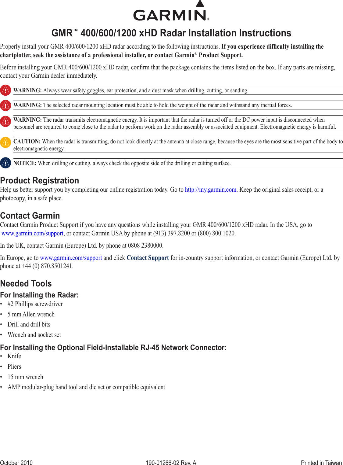
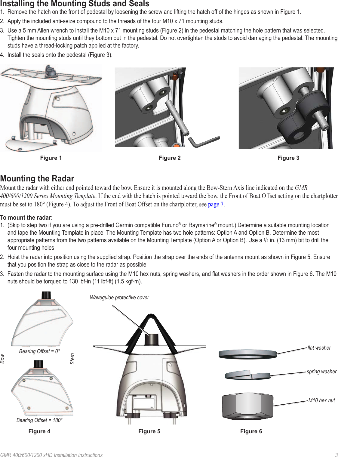
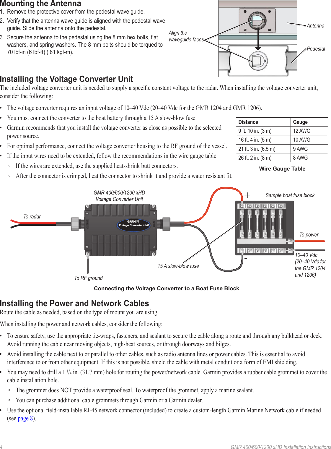
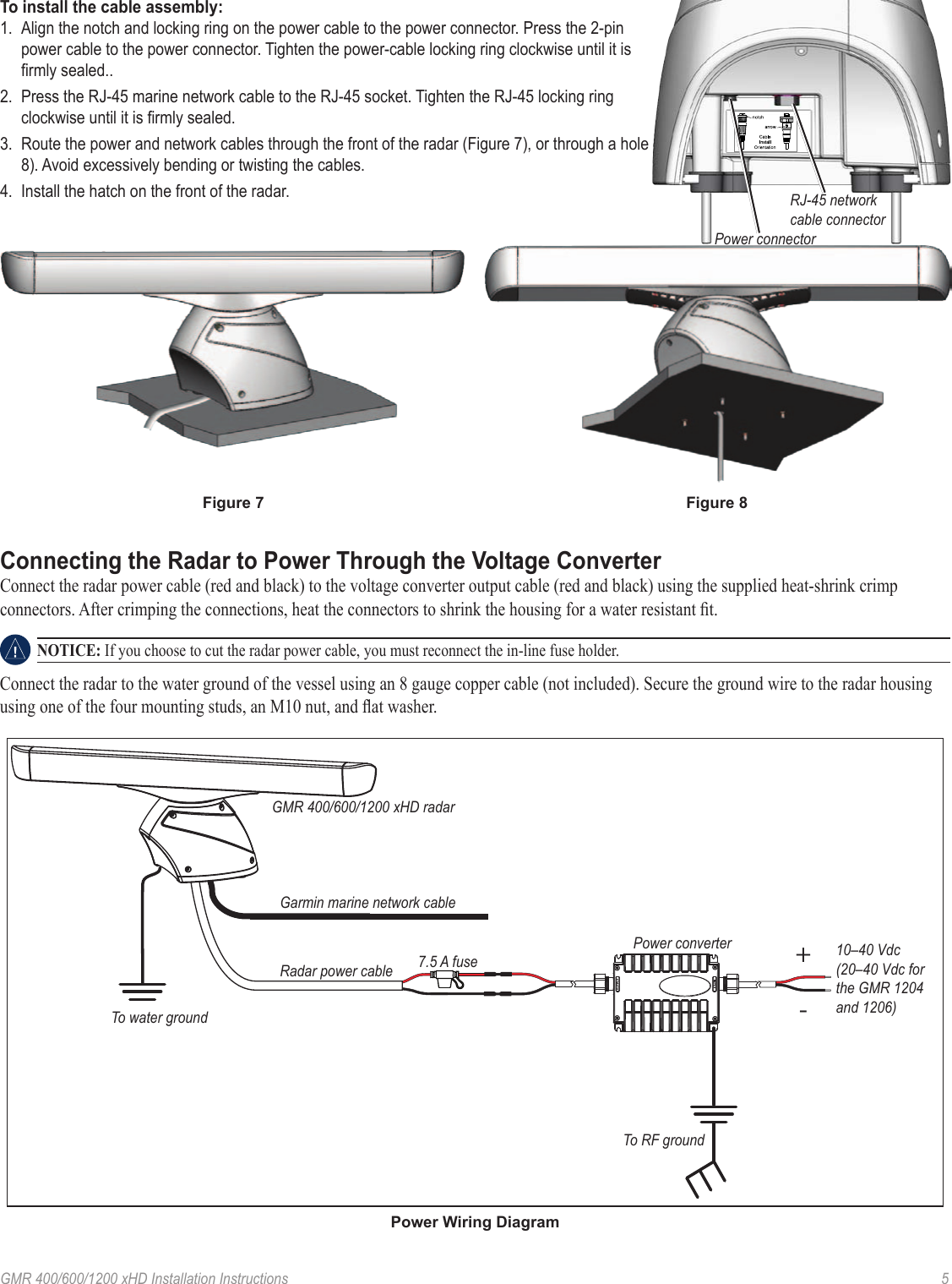
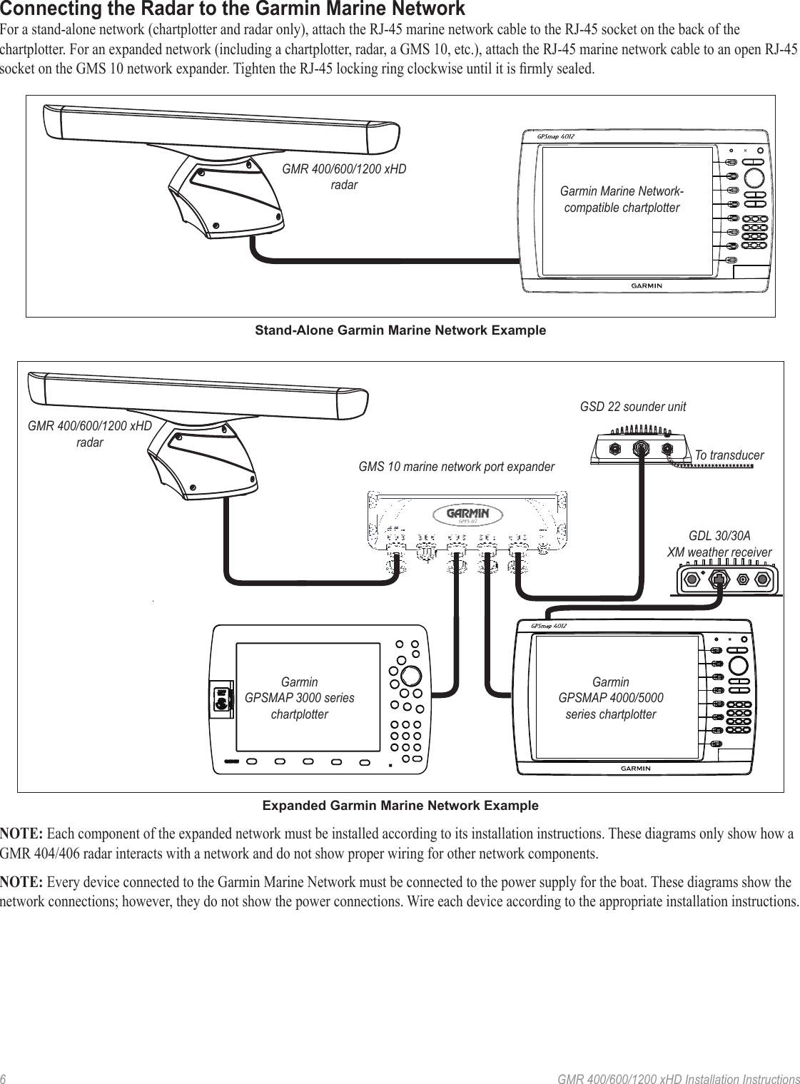
![2 GMR 400/600/1200 xHD Installation InstructionsSelecting a LocationWhen selecting a location to install the GMR 400/600/1200 xHD radar, consider the following:• An ideal mounting location is high above the keel line of the ship with a minimal part of the structure or rigging blocking the radar beam. Obstructions in the path of the radar beam may cause blind and shadow sectors, or generate false echoes. The higher the installation position, the farther the radar can detect targets. • Avoid mounting on the same level as smoke stacks, horizontal spreaders, or crosstrees on a mast. • Do not install the radar near heat sources where it may be exposed to smoke or hot air from smoke stacks or heat from lights.• The mounting surface or platform should be sturdy enough to support the weight of the radar and any inertial forces, as at as possible, and parallel with the water line. • Garmin recommends mounting the radar out of range of personnel (vertical beam width above head height). When properly installed and operated, the use of this radar conforms to the requirements of ANSI/IEEE C95.1-1992 Standard for Safety Levels with Respect to Human Exposure to Radio Frequency Electromagnetic Fields.IEC 60936-1 clause 3-27.1 states maximum distances from the antenna at which Radio Frequency (RF) levels can be expected. ◦ GMR 404 xHD (100W/m squared = 55 in. [1.4 m]) (10W/m squared = 178 in. [4.5 m]) ◦ GMR 406 xHD (100W/m squared = 65 in. [1.7 m]) (10W/m squared = 200 in. [5.1 m]) ◦ GMR 604 xHD (100W/m squared = 67 in. [1.7 m]) (10W/m squared = 217 in. [5.5 m]) ◦ GMR 606 xHD (100W/m squared = 79 in. [2 m]) (10W/m squared = 244 in. [6.2 m]) ◦ GMR 1204 xHD (100W/m squared = 99 in. [2.5 m]) (10W/m squared = 307 in. [7.8 m]) ◦ GMR 1206 xHD (100W/m squared = 111 in. [2.8 m]) (10W/m squared = 343 in. [8.7 m]) When the radar is transmitting, do not look directly at the antenna at close range (the eyes are the most sensitive part of the body to electromagnetic energy). • A compass safe distance must be maintained between the compass and the radar. The compass safe distance is measured from the center point of the compass to the nearest point on the radar. ◦ Standard compass = 35 7/16 in. (90 cm) ◦ Standby Steering and Emergency compasses = 31 1/2 in. (80 cm)• Mount other electronics and cables more than 7 ft. (2 m) from the path of a radar beam. A radar beam can spread 25° vertically above and below the radiating element of the radar. For vessels with higher bow angles at cruise speed, you can lower the angle so that the beam points slightly downward to the waterline while at rest. Shims may be used as necessary.12.5°12.5°• Install the radar away from antennas or other electronics. GPS antennas should be located above or below the radar beam path of the radar. Mount at least 3 ft. (1 m) from any equipment transmitting or cables carrying radio signals, such as VHF radios, cables, and antennas. In the case of SSB radios, the distance should be increased to 7 ft. (2 m).](https://usermanual.wiki/Garmin/GMR4XXHD/User-Guide-1368647-Page-2.png)