Garmin 400W 500W Series Users Manual
GTX 330D to the manual 87ea74e3-9a09-4b9c-a2cc-d0200b8f629b
2015-01-29
: Garmin Garmin-400W-500W-Series-Users-Manual-216939 garmin-400w-500w-series-users-manual-216939 garmin pdf
Open the PDF directly: View PDF ![]() .
.
Page Count: 50
- Part One: Traffic Information Service (TIS) Interface
400W / 500W Series
Garmin Optional Displays
Pilot’s Guide Addendum For:
• GDL 69/69A XM Satellite Datalink
• GTX 330/330D TIS
• Garmin TAWS (GPS 500W & GNS 530W)
Foreward
This Pilot’s Guide Addendum is written for:
•Garmin GPS 400W, GNC 420W/420AW, and GNS 430W/430AW Main System Software Version 2.00, 3.00, 3.30, or later
•GarminGPS500W&GNS530W/530AWMainSystemSoftwareVersion 2.00, 3.00, 3.30, or later
•GTX330/330DMainSoftwareVersion4.05
•GDL69/69AMainSoftwareVersion3.02orlater
Some differences in operation may be observed when comparing the information in this manual to earlier or later software versions.
©2009GarminLtd.oritssubsidiaries.AllRightsReserved.
GarminInternational,Inc.,1200East151stStreet,Olathe,KS66062,U.S.A.
Tel.913/397.8200or800/800.1020 Fax913/397.8282
GarminAT,Inc.,2345TurnerRd.,S.E.,Salem,Oregon97302,U.S.A.
Tel:503/581.8101 Fax:503/364.2138
Garmin(Europe)Ltd.,LibertyHouse,BullsCopseRoad,HounsdownBusinessPark,Southhampton,SO409RB,U.K.
Tel.+44(0)8708501243 Fax+44(0)2380524004
GarminCorporation,No.68,Jangshu2ndRoad,Shijr,TaipeiCounty,Taiwan
Tel.886/2.2642.9199 Fax886/2.2642.9099
Exceptasexpresslyprovidedherein,nopartofthisaddendummaybereproduced,copied,transmitted,disseminated,downloaded,
orstoredinanystoragemedium,foranypurposewithouttheexpresspriorwrittenconsentofGarmin.Garminherebygrantspermis-
sion to download a single copy of this manual and of any revision to this manual onto a hard drive or other electronic storage medium
to be viewed and to print one copy of this manual or of any revision hereto, provided that such electronic or printed copy of this manual
orrevisionmustcontainthecompletetextofthiscopyrightnoticeandprovidedfurtherthatanyunauthorizedcommercialdistribution
ofthismanualoranyrevisionheretoisstrictlyprohibited.Informationinthisdocumentissubjecttochangewithoutnotice.Garmin
reservestherighttochangeorimproveitsproductsandtomakechangesinthecontentwithoutobligationtonotifyanypersonororga-
nizationofsuchchangesorimprovements.
Garmin® is a registered trademark, and GTX™ and GDL™ are trademarks of Garmin Ltd. or its subsidiaries and may
not be used without the express permission of Garmin Ltd. or its subsidiaries.
July2009190-00356-30RevisionF
190-00356-30 Rev F
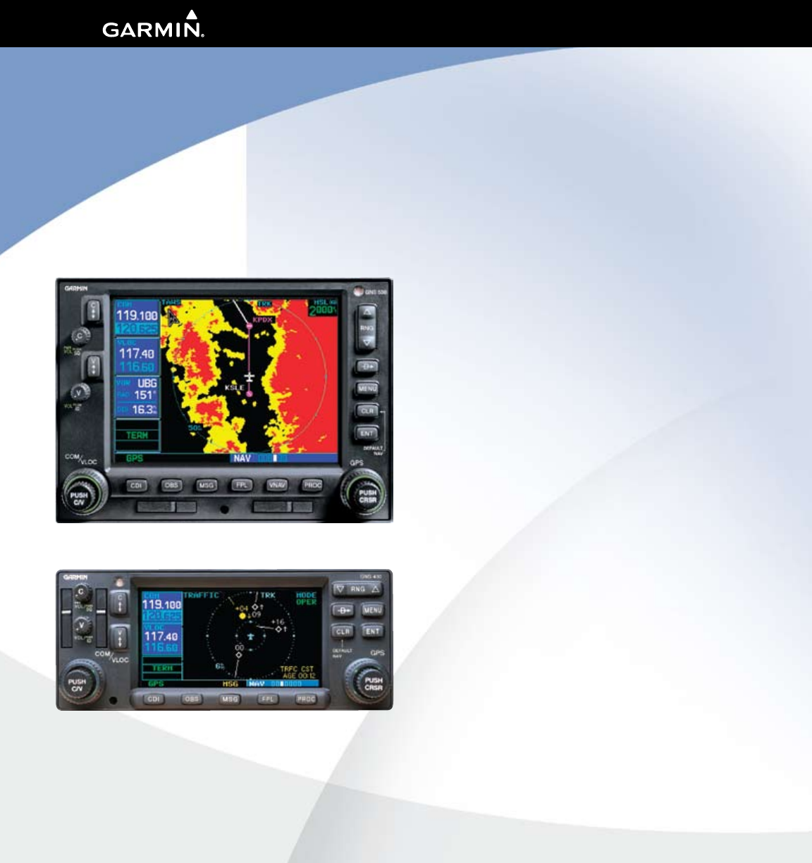
The screen display examples shown in this
addendum are taken from the GNS 430W
and GNS 530W. TIS and Weather Data Link
Display Interface functionality is the same
for the 400W and 500W Series Units. TIS
Traffic Display and Weather Data Link are
available only when the 400W/500W units
are configured with the GTX 330 Mode S
Transponder and GDL 69/69A Data Link
Transceiver, respectively.
i
Introduction
Warnings and Cautions
WARNING: Terrain data are obtained from third party sources. Garmin is not able to independently verify the accuracy of this
data which should be used only as an aid for situational awareness. Terrain data must not be used as the sole basis for deci-
sions or maneuvers to avoid terrain or obstacles. Terrain data must not be used for navigation.
CAUTION: Use the 400W/500W Series Units at your own risk. To reduce the risk of unsafe operation, carefully review and
understand all aspects of the Owner’s Manual and the Flight Manual Supplement, and thoroughly practice basic operation
prior to actual use.
CAUTION: The Global Positioning System is operated by the United States government, which is solely responsible for its
accuracy and maintenance. The system is subject to changes which could affect the accuracy and performance of all GPS
equipment. Although Garmin 400W/500W Series Units are precision electronic NAVigation AIDS (NAVAID), any NAVAID can be
misused or misinterpreted and therefore become unsafe.
CAUTION: Use the Weather Data Link Interface, TIS, TAWS, and TERRAIN at your own risk. To reduce the risk of unsafe opera-
tion, thoroughly practice basic operation prior to actual use. When in actual use, carefully compare indications from the
Garmin unit to all available navigation sources, including the information from other NAVAIDS, visual sightings, charts, etc.
For safety, always resolve any discrepancies before continuing navigation. The GPS altitude format calculated by the Garmin
400W/500W Series units is geometric height above mean sea level and could vary significantly from altitude displayed by pres-
sure altimeters in aircraft. Never use GPS altitude to determine aircraft altitude.
CAUTION: The Jeppesen database incorporated in the Garmin 400W/500W Series Units must be updated regularly in order to
ensure that its information is current. Updates are released every 28 days. A database information packet is included in your
Garmin 400W/500W Series Unit package. Pilots using an out-of-date database do so entirely at their own risk.
CAUTION: The Weather Data Link, TIS, TAWS, and TERRAIN information contained in this Pilot’s Guide Addendum is not
intended to replace the documentation that is supplied with the applicable Garmin 400W/500W Series Unit and the GTX 330
Transponder. The user must know how to operate the 400W/500W Series Unit and be knowledgeable of the information in the
400W/500W Pilot’s Guide.
TIS CAUTION: TIS is NOT intended to be used as a collision avoidance system and does not relieve pilot responsibility to “see
and avoid” other aircraft. TIS should not be used for avoidance maneuvers during IMC or other times when there is no visual
contact with the intruder aircraft. TIS is intended only to assist in visual acquisition of other aircraft in VMC. Avoidance maneu-
vers are not recommended, nor authorized, as a direct result of a TIS intruder display or TIS alert.
While TIS is a useful aid to visual traffic avoidance, it has some system limitations that must be fully understood to ensure
proper use. Many of these limitations are inherent in secondary radar surveillance. In other words, the information provided by
TIS will be no better than that provided to ATC.
CAUTION: Garmin would like to remind pilots flying with GDL 69/69A-equipped aircraft that TFRs are only advisory and
are not a replacement for a thorough preflight briefing on TFR times and locations. Always confirm TFR data through official
sources and contact your Flight Service Station for interpretation of TFR data.
190-00356-30 Rev F

ii
Introduction
Table of Contents
Table of Contents
Part One: Traffic Information Service (TIS) Interface 1
Section 1: TIS Operation and Symbology ....................1
TIS Operation ............................................................................1
How TIS differs from TCAS .........................................................2
TIS Limitations ..........................................................................2
Improving TIS ............................................................................3
TIS Symbology ..........................................................................3
Section 2: Control and Display .....................................5
TIS Traffic Display Status and Pilot Response ..............................5
Traffic Page ...............................................................................6
Traffic Page Display Range ........................................................6
Map Page .................................................................................7
Configuring TIS Traffic Data on the Map Page .......................7
Highlighting TIS Traffic Using Map Page Panning ........................8
Section 3: TIS Operational Procedures ........................9
Introduction ..............................................................................9
Power-Up Test ...........................................................................9
Manual Override .....................................................................10
Flight Procedures ....................................................................10
After Landing ..........................................................................10
Part Two: XM Radio .....................................................11
Section 1: Introduction ...............................................11
Overview ................................................................................11
XM Radio Pages .....................................................................11
XM NAV Pages ..................................................................11
XM WPT Pages ..................................................................12
XM AUX Pages ..................................................................12
Section 2: XM Weather ................................................12
Weather Product Age ..............................................................13
XM NEXRAD Weather .............................................................13
NEXRAD Intensity ..............................................................14
NEXRAD Abnormalities ......................................................15
NEXRAD U.S. and Canadian Coverage ...............................15
NEXRAD Limitations ..........................................................16
XM Weather METARs ..............................................................16
Textual METAR Page ..........................................................17
Textual METAR/TAF Code ..................................................19
TAF Page ...........................................................................19
TFR Information.................................................................19
Lightning (LTNG) .....................................................................20
Cell Movement (CELL MOVE) ..................................................21
Winds Aloft .............................................................................22
Winds Aloft Altitude ..........................................................23
Section 3: XM AUX Pages .............................................23
XM Information Page .............................................................23
XM WX Timestamps ................................................................24
Section 4: XM Audio .....................................................25
XM Audio Menu .....................................................................27
Add to Presets List ..................................................................27
Enter Channel Number ............................................................28
Display Channel In List ............................................................28
Display Artist In List ................................................................29
Display Title In List ..................................................................29
Enable/Mute Audio Output ......................................................30
Change Volume ......................................................................30
Part Three: TAWS Interface .........................................31
Section 1: Introduction ...............................................31
Overview ................................................................................31
Operating Criteria ...................................................................31
Limitations ..............................................................................31
Section 2: TAWS Operation .........................................32
TAWS Alerting.........................................................................32
Baro-Corrected Altitude ..........................................................32
Power Up ...............................................................................32
TAWS Page .............................................................................32
Inhibit Mode ...........................................................................33
External TAWS Inhibit Control ............................................34
TAWS Manual Test ..................................................................34
TAWS Symbols ........................................................................35
General Database Information .................................................36
Database Versions ...................................................................36
Database Updates ..................................................................37
Terrain/Obstacle Database Areas of Coverage ..........................37
Section 3: TAWS Alerts ................................................38
Forward Looking Terrain Avoidance .........................................38
Premature Descent Alerting (PDA) ...........................................39
Excessive Descent Rate Alert (EDR) ..........................................40
Negative Climb Rate After Takeoff Alert (NCR) .........................41
“Five-Hundred” Aural Alert .....................................................42
TAWS Not Available Alert ........................................................42
TAWS Failure Alert ..................................................................42
TAWS Alert Summary ..............................................................42
Pilot Actions ...........................................................................44
190-00356-30 Rev F
1
Part One: Section 1
Part One:
Traffic Information Service
(TIS) Interface
Section 1: TIS Operation and
Symbology
TIS Operation
NOTE: Part One of this Addendum assumes the user
has experience operating the 400W/500W Series units
and the Garmin GTX 330 Transponder.
The Traffic Information Service (TIS) provides
a graphic display of traffic advisory information in
thecockpitfornon-TCAS(TrafcalertandCollision
Avoidance System) equipped aircraft. TIS is a ground-
basedserviceprovidingrelativelocationofallATCRBS
(AirTrafcControlRadarBeaconSystem)ModeA
and Mode C transponder-equipped aircraft within a
specified service volume. The TIS ground sensor uses
real-timetrackreportstogeneratetrafcnotication.
TIS Traffic display is available to aircraft equipped
withaModeSDataLinksuchastheGarminGTX330
Transponder.TISTrafcfromaGTX330Transpon-
dercanthenbedisplayedonaGarmin400W/500W
Series unit. Surveillance data includes all transponder-
equipped aircraft within the coverage volume. Aircraft
without an operating transponder are invisible to TIS.
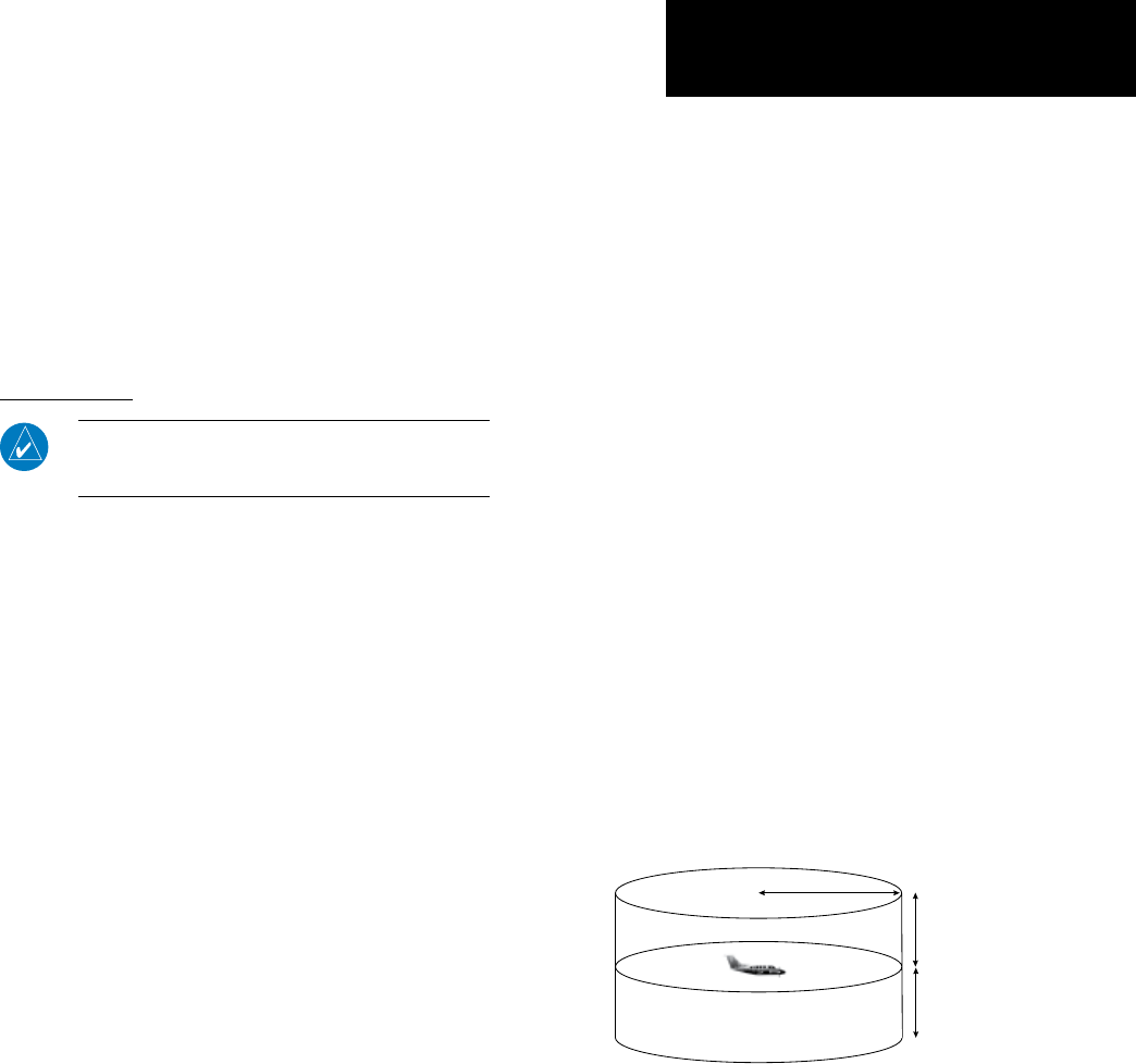
TIS displays up to eight traffic targets within seven
nautical mileshorizontallyfrom3000feetbelowto
3500feetabovethe requesting aircraft.
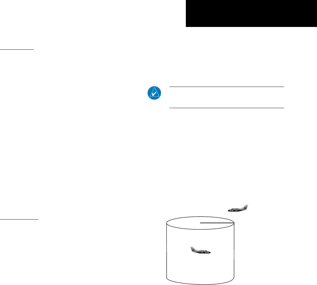
The TIS is a ground-based service that displays
nearbyaircraftonyour400W/500W-seriesdisplay.
FortheTISfeaturetoinformyouofanearbyaircraft’s
presence, several conditions must be met:
• YouraircraftmustbeequippedwithaModeS
datalinktransponder,suchastheGTX330.
• YoumustbewithinrangeofaModeSradar
that provides the TIS service. Not all Mode S
ground radars provide TIS service.
• The“intruder”aircraftmustbeequippedwith
a transponder, and that transponder must be
turned on. Aircraft that are not equipped with
operating transponders will not be visible to the
Mode S surveillance radar.
• The“intruder”aircraftmustbewithintheTIS
coverage volume for your aircraft. TIS displays
up to eight traffic targets within seven nautical
mileshorizontallyfromtherequestingaircraft,
andfrom3,000feetbelowto3,500feetabove
the requesting aircraft.
• Bothyouraircraftandtheintruderaircraftmust
be visible to the Mode S surveillance radar on
the ground.
Always remember that TIS cannot alert you to
the presence of aircraft that are not equipped with
transponders, nor can it alert you to aircraft that may
be nearby, but obscured from the ground surveillance
radar by intervening terrain.
TIS Coverage Volume (not to scale)
7.0 nm 3,500 ft
3,000 ft
TIS Operation and Symbology
190-00356-30 Rev F
2
TIS Operation and Symbology
Part One: Section 1
How TIS differs from TCAS
The main difference between TIS and TCAS is the
source of surveillance data. TCAS uses an airborne
interrogator with a one-second update rate, while TIS
uses the terminal Mode S ground interrogator and its
DataLinktoprovideaboutave-secondupdaterate.
The range accuracy of TIS and TCAS is similar.
TIS Limitations
NOTE: This section on TIS Limitations is not compre-
hensive. Garmin recommends the user review the TIS
Limitations section of the Aeronautical Information
Manual, Section 1-3-5.
TIS is NOT intended to be used as a collision
avoidance system and does not relieve the pilot of
responsibilityto“seeandavoid”otheraircraft.TIS
should not be used for avoidance maneuvers during
IMC or other times when there is no visual contact
with the intruder aircraft. TIS is intended only to assist
in visual acquisition of other aircraft in VMC. No rec-
ommended avoidance maneuvers are provided for, nor
authorized,asadirectresultofaTISintruderdisplay
or TIS advisory.
While TIS is a useful aid to visual traffic avoid-
ance, it has some system limitations that must be fully
understood to ensure proper use. Many of these limi-
tations are inherent in secondary radar surveillance.
In other words, the information provided by TIS will
be no better than that provided to ATC. TIS will only
display aircraft with operating transponders installed.
TIS relies on surveillance of the Mode S radar,
whichisa“secondarysurveillance”radarsimilartothe
ATCRBS.TISoperationmaybeintermittentduring
turns or other maneuvering. TIS is dependent on
two-way,“line-of-sight”communicationbetweenthe
aircraft and the Mode S radar. Whenever the structure
of the client aircraft comes between the transponder
antenna (usually located on the underside of the air-
craft) and the ground-based radar antenna, the signal
may be temporarily interrupted. Other limitations and
anomalies associated with TIS are described in the
AIM,Section1-3-5.
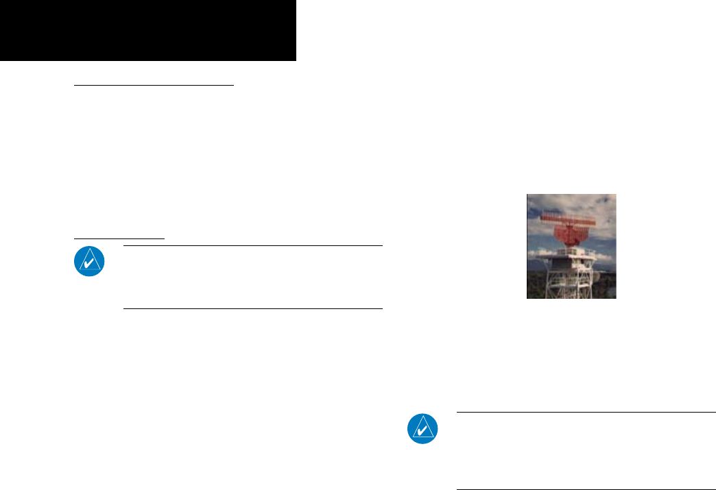
Garmin is not responsible for Mode S geo-
graphical coverage. Operation of the ground
stations is the responsibility of the FAA. Refer
to the Aeronautical Information Manual for a
Terminal Mode S Radar Site Map covering the
U.S.
NOTE: TIS will be unavailable at low altitudes in many
areas of the U.S., particularly in mountainous regions.
Also, when flying near the “floor” of radar coverage
in a particular area, intruders below the client aircraft
may not be detected by TIS.
TIS information is collected one radar scan prior to
thescanduringwhichtheuplinkoccurs.Therefore,
thesurveillanceinformationisapproximatelyve
secondsold.Inordertopresenttheintrudersina“real
time”position,theTISgroundstationusesa“predic-
tivealgorithm”initstrackingsoftware.Thisalgorithm
usestrackhistorydatatoextrapolateintrudersto
theirexpectedpositionsconsistentwiththetimeof
displayinthecockpit.Occasionally,aircraftmaneuver-
ing will cause this algorithm to induce errors in the
400W/500Wdisplay.Theseerrorsprimarilyaffectrela-
tivebearinginformationandtrafctargettrackvector
(it will lag); intruder distance and altitude will remain
relativelyaccurateandmaybeusedtoassistin“see
190-00356-30 Rev F
3
TIS Operation and Symbology
Part One: Section 1
andavoid.”Someofthemorecommonexamplesof
these errors follow:
• Whenclientorintruderaircraftmaneuversexces-
sively or abruptly, the tracking algorithm may
report incorrect horizontal position until the
maneuveringaircraftstabilizes.
• When a rapidly closing intruder is on a course that
crosses the client aircraft course at a shallow angle
(eitherovertakingorheadon)andeitheraircraft
abruptly changes course within ¼ NM, TIS may
display the intruder on the opposite side of the
client than it actually is.
These are relatively rare occurrences and will
be corrected in a few radar scans once the course
has stabilized.
Improving TIS
UsersofTIScanrendervaluableassistancein
the correction of malfunctions by reporting their
observationsofundesirableperformance.Reporters
should identify the time of observation, location, type
and identity of aircraft, and describe the condition
observed; the type of transponder processor and soft-
ware in use can also be useful information. Since TIS
performance is monitored by maintenance personnel
other than ATC, it is suggested that malfunctions be
reported in the following ways:
• BytelephonetothenearestFlightServiceStation
(FSS)facility.
• ByFAAForm8000-7,SafetyImprovementReport,
a postage-paid card designed for this purpose.
ThesecardsmaybeobtainedatFAAFSSs,General
AviationDistrictOfces,FlightStandardsDistrict
Ofces,andGeneralAviationFixedBasedOpera-
tions.
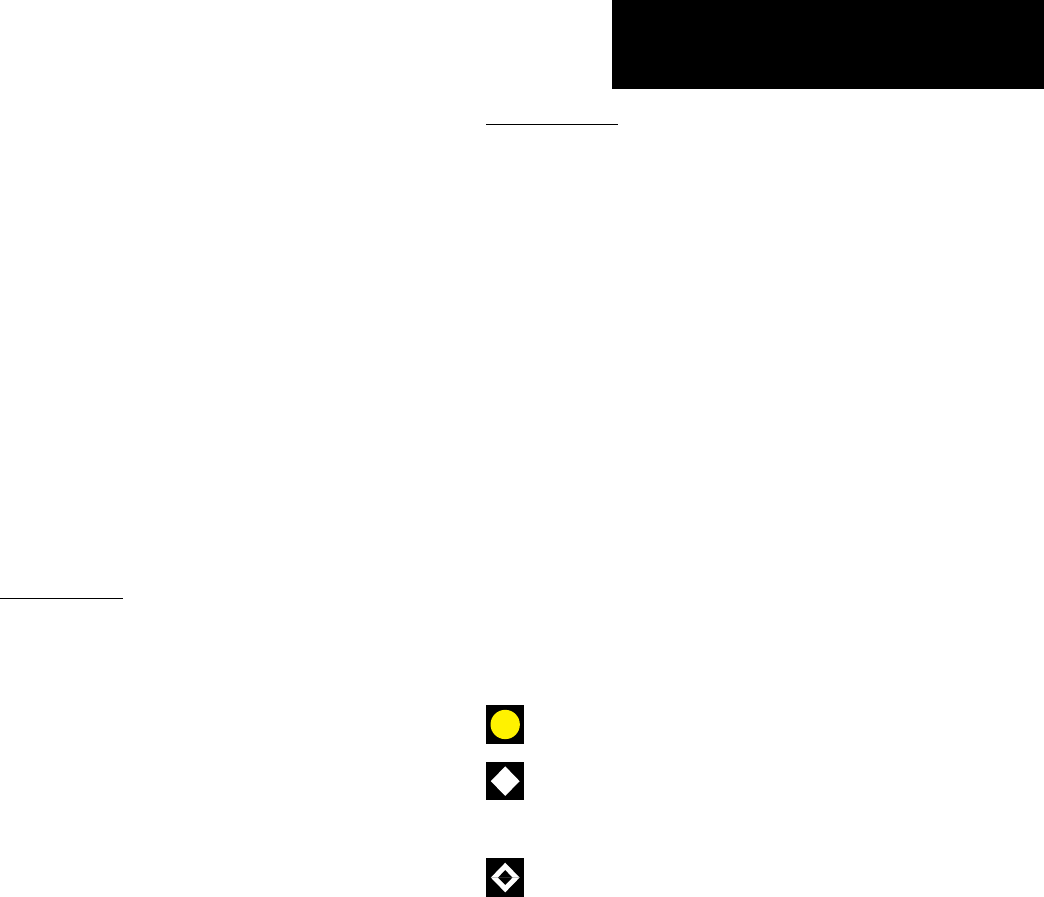
TIS Symbology
TIStrafcisdisplayedonthe400W/500WSeries
unit according to TCAS symbology, graphically dis-
played on a dedicated graphical page (Traffic Page;
see below), and on the moving Map Page. A Traffic
Advisory (TA) symbol appears as a solid yellow circle
(or half circle on the outer range ring if the traffic is
outsidetherangeofthededicatedTrafcPage).Prox-
imity Advisories (PA) are displayed as a solid diamond,
and other traffic is displayed as an open diamond. PA
and other traffic is normally displayed in white, or it
may be alternatively configured for display in cyan.
When configured for cyan, the traffic page range rings
andmarkingsaredisplayedinwhite.Altitudedevia-
tion from own aircraft altitude is displayed above the
target symbol if traffic is above own aircraft altitude,
and below the symbol if they are below own aircraft
altitude. Altitude trend is displayed as an up arrow
(>+500ft/min),downarrow(<-500ft/min),orno
symboliflessthan500ft/minrateineitherdirection.
•TrafcAdvisories(TA)—Yellow
•ProximityAdvisories(PA)—White
(may be configured as Cyan)
•Other—White(maybeconguredasCyan)
190-00356-30 Rev F
4
TIS Operation and Symbology
Part One: Section 1
Own Aircraft
“Other” Traffic—This symbol represents
traffic detected within the selected display
range that does not generate a TA.
Traffic Advisory (TA)—This symbol is generated when traffic
meets the advisory criteria described in TIS Operational Proce-
dures.
Traffic Ground Track is indicated
on the 400W/500W display by a
“target track vector”, a short line
displayed in 45-degree increments.
This vector shows the flight direc-
tion of the traffic.
The TIS audio alert is generated from the
GTX 330 whenever the number of Traffic Ad-
visories on the 400W/500W display increases
from one scan to the next. Limiting Traffic
Advisories only reduces the “nuisance” alerting
due to proximate aircraft. For example, when
the first Traffic Advisories appears on the TIS
display, the user is alerted audibly. So long as
a single aircraft remains on the TIS display, no
further audio alert is generated. If a second (or
more) aircraft appears on the display, a new
audio alert is sounded.
If the number of Traffic Advisories on the TIS
display decreases and then increases, a new
audio alert is sounded. The TIS audio alert is
also generated whenever TIS service becomes
unavailable. The volume, pitch, and duration
of the audio alert (including the choice between
a male or female voice) is configured during
installation.
The following TIS audio alerts are available:
• “Traffic” —TIS traffic alert is received.
• “Traffic Not Available” — TIS service is not
available or out of range.
190-00356-30 Rev F
5
Part One: Section 2
TIS Controls and Display
Section 2: Control and Display
TIS Traffic Display Status and Pilot Response
•STBY—Whenthe400W/500WdisplaysSTBY
in the upper right hand corner of the display the
TIS system is in standby mode and cannot display
traffic data.
•OPER—Whenthe400W/500WdisplaysOPER
in the upper right hand corner of the display the
TIS system is in operational mode and available
to display traffic on the Traffic or Map Page.
•AGE — If traffic data are not refreshed within
6seconds,anageindicator(e.g.,“AGE00:06”)
is displayed in the lower right corner of the dis-
play (when displaying traffic). The pilot should
be aware that the quality of displayed traffic is
reduced in this condition.
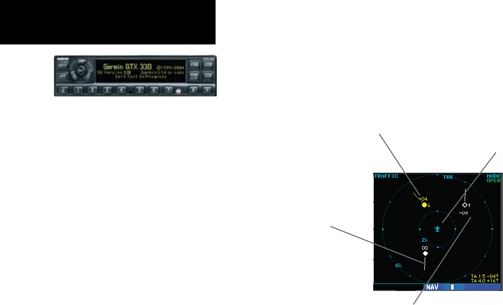
•TRFCCST—If data are still not received between
sixandtwelveseconds,the“TRFCCST”(trafc
coasting) banner located above the AGE timer will
indicate that displayed traffic is held even though
the data are not current. The pilot should be aware
that the quality of displayed traffic is reduced in
this condition.
Traffic Age Indication showing “traffic coasting”.
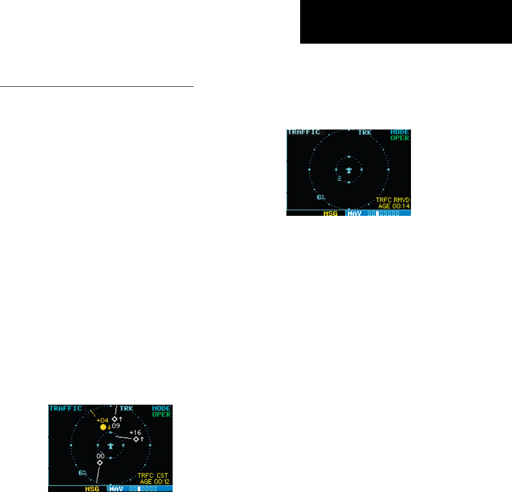
•TRFCRMVD—If data are still not received after
twelve seconds, the“TRFCRMVD”bannerwill
indicate that traffic has been removed from the
display due to the age of the data being too old
to“coast”(forthetimeperiodafter12seconds
from the last receipt of a TIS message). The pilot
should be aware that traffic may be present but
not shown.
Traffic Page displaying “TRFC RMVD”
banner.
•UNAVAIL—Aftera60secondperiodelapses
with no data, TIS is considered to be unavailable.
Thisstateisindicatedbythetext“UNAVAIL”.
Thepilotshouldbeawarethat“UNAVAIL”could
indicate a TIS coverage limitation due to a line-
of-sight situation, a low altitude condition, no
TIS service, or a result of flying directly over the
radar site providing coverage (cone of silence).
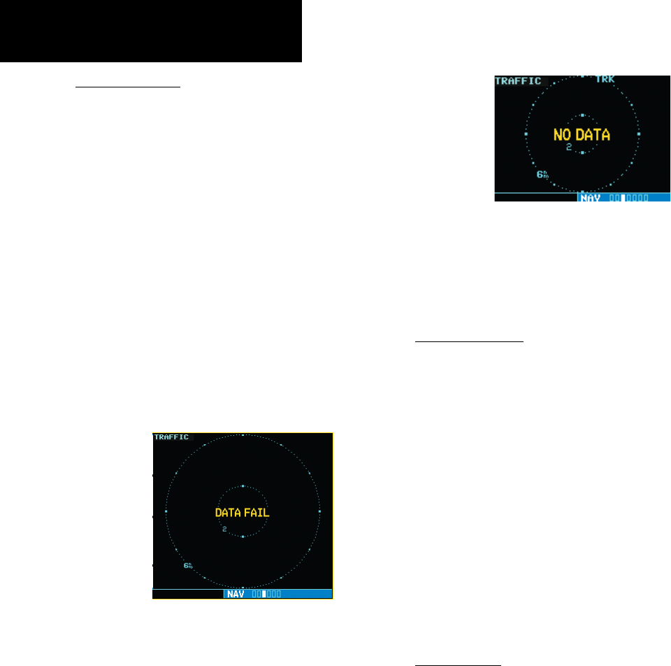
•NODATA—“NODATA”isdisplayedwhenno
dataarebeingreceivedfromtheGTX330.The
pilot should be aware that this status may be a
normal mode of operation in a dual transpon-
derinstallationwheretheGTX330withTISis
nottheselectedtransponder.TheGTX330may
not be powered on.
•DATAFAIL—“DATAFAIL”isdisplayedwhen
dataarebeingreceivedfromGTX330,butthere
was a failure detected in the data stream. The
pilot should see the dealer for corrective action.
•FAILED—“FAILED”isdisplayedwhenthe
GTX330hasindicatedithasfailed.Thepilot
should see the dealer for corrective action.
190-00356-30 Rev F
6
Part One: Section 2
TIS Controls and Display
Traffic Ground Track
Trafcgroundtrackisindicatedinthe
400W/500Wdisplaybya“targettrackvector”,ashort
linedisplayedin45°increments,extending in the
direction of target movement.
Traffic Target Track Vector.
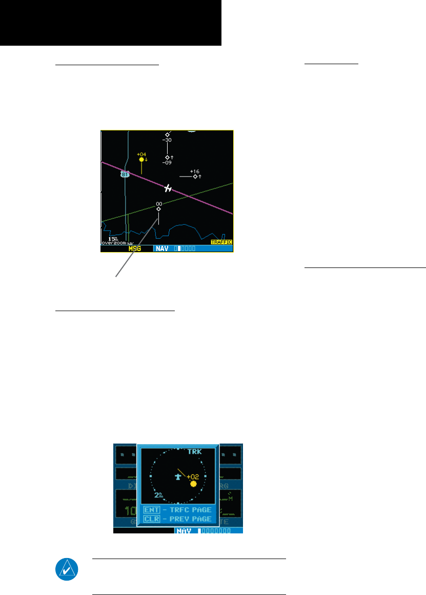
Traffic Warning Window
When the unit is on any page (other than the
NAVTrafcPageorwhenaTAWS/Terrain,orDead
Reckoningpop-upisdisplayed)andatrafcthreatis
imminent, the Traffic Warning Window is displayed.
The Traffic Warning Window shows a small thumb-
nailmapwhichcantaketheusertotheTrafcPage
by pressing ENT,orgobacktothepreviouspageby
pressing CLR.
Traffic Warning Window
NOTE: The Traffic Warning Window is disabled when
the aircraft ground speed is less than 30 knots or when
an approach is active.
Traffic Page
TISTrafcdataaredisplayedontwo400W/500W
Series unit pages, the Traffic Page and the Map Page.
The500WSeriesunitcanalsobeconguredto
displayatrafcthumbnailwindowbelowtheVLOC
frequencywindow.Unlikeotherformsoftrafc,TIS
traffic does not require heading data to be valid on the
map. The only difference between TIS and other traffic
data occurs on the Traffic Page. If heading is available,
then the traffic data are compensated and displayed
as heading-up. If it’s not available, the Traffic Page is a
track-updisplay.Itislabeledontheupperportionof
the Traffic Page.
Traffic Page Display Range
Various display ranges can be selected for optimal
display of TIS traffic information.
To change the display range on the Traffic Page:
Press RNG to zoom through the range selec-
tions which are: 12/6 NM, 6/2 NM, and
2 NM.
190-00356-30 Rev F
7
TIS Controls and Display
Part One: Section 2
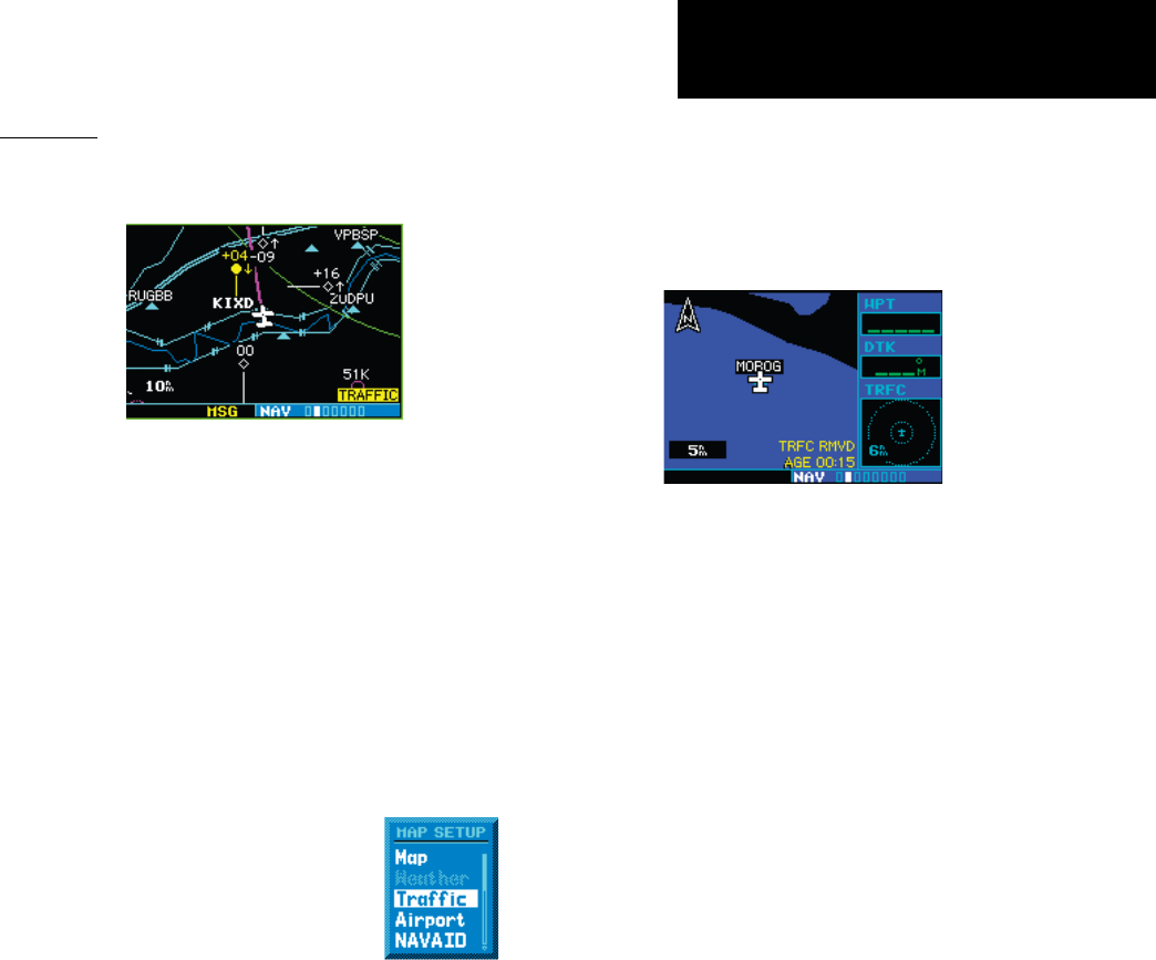
Map Page
TIS traffic is displayed on the Map Page in addition
to the Traffic Page.
The Map Page displaying traffic.
Configuring TIS Traffic Data on the Map Page
To configure TIS traffic on the Map Page:
1. Turn the small right knob to select the Map
Page.
2. Press the MENU key.
Turn the small right knob to select “Setup
Map?”
3. The flashing cursor highlights the GROUP field.
Turn the small right knob to select “Traffic” and
press ENT.
4. Turn the large right knob to
select the desired Traffic Mode
option. Turn the small right
knob to select the desired option
and press ENT. Repeat the step
for Traffic Symbol and Traffic
Label.
5. Press CLR to return the Map Page.
The traffic mode selection menu allows the user to
choose from the following:
• Alltrfc-AlltrafcisdisplayedontheMapPage.
• TA/PA-Onlytrafcadvisoriesandproximity
advisories are displayed on the Map Page.
• TAonly-Onlytrafcadvisoriesaredisplayedon
the Map Page.
FromtheMapPageyoucandisplaytrafcin
a thumbnail format in any of the top three (400W
Series)orfour(500WSeries)dataeldsontheright
side of the Map Page.
Thumbnail Traffic displayed on the
GNS 430W.
NOTE: The thumbnail will display traffic
coasting “TRFC CST” or traffic removed
“TRFC RMVD” in the lower right when TIS
messages have been missed.
To display Thumbnail Traffic on the Map Page:
1. Turn the small right knob to select the Map
Page.
2. Press the MENU key and display the Page Menu.
3. Turn the small right knob to select “Change
Fields?” and press ENT.
4. Select one of the top three (400W Series) or four
(500W Series) configurable fields. Select ‘TRFC’
from the Select Field Type List and press ENT. Note
that the thumbnail range defaults to 6 NM and
cannot be changed.
190-00356-30 Rev F
8
TIS Controls and Display
Part One: Section 2
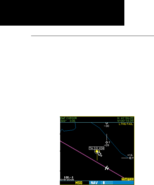
Highlighting TIS Traffic Using Map Page Panning
Another Map Page feature is panning, which allows
you to move the map beyond its current limits without
adjustingthemapscale.Whenyouselectthepanning
function—bypressingthesmall right knob—a
target pointer will flash on the map display. A window
also appears at the top of the map display showing
the latitude/longitude position of the pointer, plus the
bearing and distance to the pointer from your present
position.
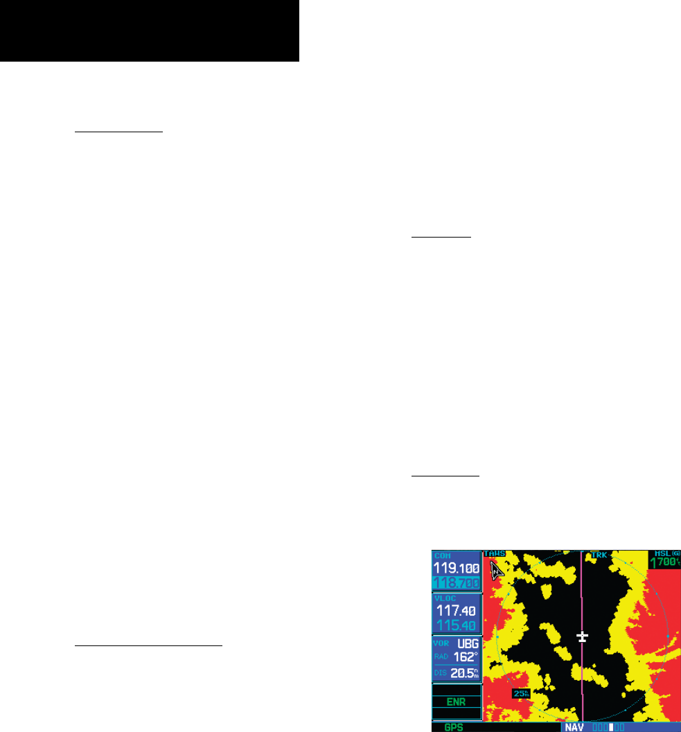
Displaying traffic range and altitude separa-
tion using the Map Panning feature.
To activate the panning feature and pan the map
display:
1. Press the small right knob to activate the panning
target pointer.
2. Turn the small right knob to move up (turn clock-
wise) or down (counterclockwise).
3. Turn the large right knob to move right (turn
clockwise) or left (counterclockwise).
4. To cancel the panning function and return to your
present position, press the small right knob.
When the target pointer is placed on traffic, the
traffic range and altitude separation are displayed.
190-00356-30 Rev F
9
TIS Operational Procedures
Part One: Section 3
Section 3: TIS Operational Procedures
Introduction
TIS warns the user with voice and visual traffic
advisories whenever it predicts an intruder to be a
threat (see illustration). Voice and visual data are sent
fromtheGTX330.Theusershouldnotstartevasive
maneuversusinginformationfromthe400W/500W
display or on a traffic advisory only. The display and
advisories are intended only for assistance in visually
locatingthetrafc,duetothelackinresolutionand
coordination ability. The flight crew should attempt
to visually acquire the intruder aircraft and maintain
a safe separation in accordance with the regulatory
requirements and good operating practice. If the flight
crew cannot visually acquire the aircraft, they should
contact ATC to obtain any information that may assist
concerningtheintruderaircraft.Basedontheabove
procedures,minoradjustmenttotheverticalight
path consistent with air traffic requirements are not
considered evasive maneuvers.
Power-Up Test
The TIS interface performs an automatic test
during power-up.
•If the system passes the power-up test, the
Standby Screen appears on the Traffic Page.
•Ifthesystempassesthepower-uptestandthe
aircraft is airborne (as determined by system
configuration at the time of installation, see
your installer for detailed criteria information),
traffic is displayable on the Traffic Page in oper-
ating mode.
•Ifthesystemfailsthepower-uptest,the“NO
DATA”,“DATAFAIL”,or“FAILED”message
is displayed. See your installer for corrective
actionifthe“DATAFAIL”,or“FAILED”message
isdisplayed.The“FAILED”messageindicates
theGTX330hasfailed.The“DATAFAIL”mes-
sage indicates data are being received from the
GTX330butafailurewasdetectedinthedata
stream.The“NODATA”messageindicatesthat
dataarenotbeingreceivedfromtheGTX330.
NOTE: “NO DATA” may be a normal mode of opera-
tion in a dual transponder installation where the GTX
330 with TIS is not the selected transponder.
•UNAVAIL—Whena60secondperiod
elapses with no data, TIS is considered to be
unavailable.Thisstateisindicatedbythetext
“UNAVAILABLE”(500WSeries)and“UNAVAIL”
(400W Series). The pilot should be aware
that“UNAVAIL”couldindicateaTIScoverage
limitation due to a line-of-sight situation, a low
altitude condition, no TIS service, or a result
of flying directly over the radar site providing
coverage (cone of silence).
Conditions for Traffic Advisories
The following condition causes TIS to display a Traffic
Advisory (TA) on the 400W/500W Series unit:
• The intruder aircraft approaches your aircraft on
a course that will intercept (defined by a 0.5 NM
horizontal radius and a relative altitude of ± 500
feet) your course within 34 seconds.
0.5 nm
Intruder Aircraft
+ 500 ft
This area within 34 seconds - 500 ft
190-00356-30 Rev F
10
TIS Operational Procedures
Part One: Section 3
Manual Override
The user can manually switch between standby
(STBY)andoperating(OPER)modeofoperationto
manually override automatic operation.
To place the display into operating mode from the
standby mode (to display TIS traffic):
1. Turn the cursor on and highlight “STBY”.
2. Turn the small right knob to select
“OPER?”.
3. Press ENT to confirm.
To place the display into standby mode from
operating mode (to stop displaying TIS traffic):
1. Turn the cursor on and highlight “OPER”.
2. Turn the small right knob to select “STBY?”
3. Press ENT to confirm.
“DATA FAIL” Message
The ‘NO DATA’ message indicates that data
are not being received from the GTX 330.
NOTE: This may be a normal mode of opera-
tion in a dual transponder installation where
the GTX 330 with TIS is not the selected
transponder.
Flight Procedures
Once the aircraft is airborne (determined by system
configuration at the time of installation) the system
switches from standby mode to operating mode. The
400W/500WSeriesunitdisplaysOPERintheupper
right hand corner of the display and begins to display
traffic on the Traffic or Map Page.
The TIS Traffic Advisory (TA) should alert the crew
to use additional vigilance to identify the intruding
aircraft. Any time the traffic symbol becomes a yellow
circle or a voice warning is announced, conduct a
visual search for the intruder. If successful, maintain
visual contact to ensure safe operation. See Section 2:
ControlandDisplayforadescriptionofpilotresponses
to TIS display messages.
After Landing
Oncetheaircraftis“ground-borne”(determined
by system configuration at the time of installation)
the system switches from operating mode to standby
mode.The400W/500WSeriesunitdisplays“STBY”.
As described previously, both the standby and operat-
ing modes can be manually overridden by the display
controls.
190-00356-30 Rev F

11
XM Radio Introduction
Part Two: Section 1
Part Two:
XM Radio
Section 1: Introduction
Overview
TheGDL69 is a remote sensor that receives
broadcastweatherdatafromadataserviceofXMSat-
elliteRadio,Inc.TheGDL69AissimilartotheGDL
69,butalsoreceivesaudioentertainmentbroadcasts
fromanotherserviceofXMSatelliteRadio.The400W
and500Wseriesunitsserveasthedisplayandcontrol
headforyourremotelymountedGDL69/69Asatellite
radio.
BeforetheGDL69/69Acanbeused,theunit
mustbeactivatedbyXMSatelliteRadiowithaservice
subscriptionthroughXMSatelliteRadio.Pleasenote
thattheGDL69isaweatherdatalink.TheGDL69A
isaweatherdatalinkandaudioreceiver.Thedatalink
service and the audio entertainment services must be
activated separately.
YourGDL69orGDL69Aisshippedwithone
or two radio hardware identifications, respectively.
TheseIDsserveasidenticationcodesforyourXM-
equippedGDL69/69Aandareneededintheactiva-
tionprocess.TheID(s)is(are)attachedtotheActiva-
tionInstructionsandprintedonalabelonthebackof
theunit.TheIDscanalsoberetrievedthroughyour
unitintheXMInformationpageoftheAuxfunction.
Contact your dealer or customer service if you are
unabletolocatetheradiohardwareIDs.
Weatherand/oraudiodatafromyourGDL69/69A
areprovidedbyXMSatelliteRadio,acompany
separate and independent from Garmin Corporation.
HaveyourradiohardwareIDsreadybeforecontact-
ingXMSatelliteRadio.Duringtheprocess,youcan
select services for subscription. Keep in mind that the
GDL69hasnoaudiocapability,audioserviceswillnot
be available with the unit.
FollowtheGDL 69/69A XM Satellite Radio Activa-
tion Instructions (190-00355-04) enclosed with your
GDL69/69AunittoactivatetheXMproducts.
XM Radio Pages
To reach the XM pages:
1. From any page, press and hold CLR to select
the Default NAV Page. (You may skip this step
if you are already viewing any of the main
pages.)
2. Turn the large right knob to select the AUX
page group. “AUX” appears in the lower right
corner of the screen.
3. Turn the small right knob to select the XM
Audio, XM Information, or XM WX Timestamps
pages.
XMWeatherpageisdisplayedintheNAVpage
group.TheXMAudiofunctionpagesaredisplayedin
theAUXpagegroup.
XM NAV Pages
WhenaGDL69orGDL69Aisinstalled,thefol-
lowingXM-relatedpagesappearintheNAVgroupof
pages:
• MapPage.TheMappage(thesecondpage
in the NAV page group) becomes capable of
displaying weather data and the boundaries
ofareaswithTemporaryFlightRestrictions
(TFRs).
• XMWeatherPage.TheXMWeatherpageis
inserted in the NAV page group, immediately
beforetheTerrainpage.Thispageislikethemap
page,butcanshowNEXRADweatherdata,col-
oredagsshowingwhichairportshaveMETARs
(currentweatherobservations—Meteorological
AerodromeReports),Lightning(LTNG)reports,
Cell Movement, or Winds Aloft.
190-00356-30 Rev F

12
Part Two: Section 2
XM Weather
XM WPT Pages
WhenaGDL69orGDL69Aisinstalled,twoXM-
relatedpagesareaddedto“airport”pagesintheWPT
page group:
• Textual METAR Page.TheTextualMETAR
pageshowsthetextofthemostrecentMETAR
(MeteorologicalAerodromeReport)thathas
been received for an airport.
• TAF Page.TheTAFpageshowsthetextofthe
mostrecentTAF(TerminalAerodromeFore-
cast) that has been received for an airport.
XM AUX Pages
WhenaGDL69orGDL69Aisinstalled,thefol-
lowingXMpagesappearintheAUXgroupofpages:
• XM Audio Page(GDL69Aonly).SeeSection4
below for a description of this page.
• XM Information Page. This page contains
information that you will use when activat-
ingyourXMsatelliteradiosubscription.It
alsoreportstheGDL69/69A’ssoftwareversion
number.
• XM Weather Timestamp Pages. This page
show timestamp data for the most recently
receivedXMweatherdata.
Section 2: XM Weather
TheXMWeatherFunctioniscapableofdisplaying
graphicalweatherinformationthroughtheXMSatel-
liteRadioServicewhenactivatedintheoptionalinstal-
lationoftheGDL69/69A.NextGenerationWeather
Radar(NEXRAD),METARssymbols(METAR),
Lightning(LTNG),CellMovement(CELLMOVE),
andWindsAloft(WINDS)aredisplayedontheNAV
pages. The types of products available depend on the
subscriptionservicewithXMSatelliteRadio.
Once you have activated an aviation weather ser-
vicefromXMSatelliteRadio,the400W/500Wseries
unit can display the following aviation-related data:
• NEXRAD. An indication of the intensity
of weather radar echoes from the National
WeatherService’snetworkofNEXRAD(NEXt
generationRADar)sitescanbeshownonthe
XMWeatherPageandcanoptionallybeover-
laidontheMappage.(Boththesepagesarein
theNAVpagegroup.)CanadianRadarmayalso
be available.
• Radar Coverage.WheneverNEXRADis
shown, a cross-hatch pattern indicates the limits
ofNEXRADradarcoverage.Thecross-hatched
areashowswhereNEXRADinformationis
unavailable.
• Lightning (LTNG). When enabled, lightning
strikesandcellsareshownasyellow“+”
signs.Lightninginformationindicatesthe
locationofcloud-to-groundlightningstrikes.
• Cell Movement (CELL MOVE). When
enabled, Cell Movement shows the storm
cells identified by the ground-based system.
The movement is depicted by an arrow. The
tip of the arrow represents where the cell is
expectedtobein10minutesfromthetime
the cell location was determined.
190-00356-30 Rev F
13
Part Two: Section 2
XM Weather
• Winds Aloft (WINDS). The Winds Aloft
selection provides the pilot with wind speed
and direction. The winds at a given altitude
are selected in the Winds Aloft Alt below the
WINDSselection.Theselectedaltitudeis
shown along with the product time.
• Textual Meteorological Aerodrome Reports
(METARs).Whenyouzoomintoshowthe
airport symbol associated with the colored flag
foragraphicalMETAR,andmovetheMap
Pointer to highlight that airport, you can then
press ENTtoseetheTextualMETARpagefor
thatairport.TheTextualMETARpageisoneof
the airport pages of the WPT page group.
• Graphical Meteorological Aerodrome
Reports (METARs).TheXMWeatherpage(in
the NAV page group) can show colored flags
to indicate the level of current weather condi-
tionsatthoseairportsforwhichtextualMETAR
reports are available. The flags are color-coded
to indicate the severity of the current weather at
theairport:cyanforVFRconditions,greenfor
MarginalVFRconditions,yellowforIFRcondi-
tions,ormagentaofLowIFRconditions.
• Terminal Aerodrome Forecast (TAFs). A
TAFpageisaddedamongtheairportpagesof
theWPTpagegroup.TheTAFpagediffersfrom
theTextualMETARpageinthatitdescribes
forecast future weather conditions rather than
current conditions.
• Temporary Flight Restrictions (TFRs). The
boundariesofareaswithTFRsareoutlinedin
yellowontheMapandXMWeatherpagesof
theNAVpagegroup.Inthe500W-series,TFR
boundaries are also shown on the NAV main
page.Youcanobtainmoreinformationabouta
TFRbybringingupthemapcursor,movingthe
map cursor to within the yellow outlined area,
and pressing the ENTkey.
Weather Product Age
Theageofthedisplayedweatherproduct—orthe
effectivetimeofWindsAloftpredictions—isshown
intheupperrightcornerofthedisplay.Forexample,
ifNEXRADisdisplayed,“0:05”indicatesthatthedata
are five minutes old. If Winds Aloft predictions are
beingdisplayed,“10:00”indicatestheeffectivetime
for the displayed prediction is 10:00 AM.
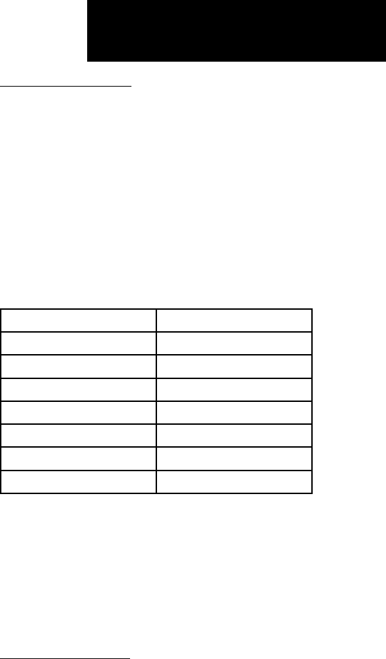
ThedataforeachXMWeatherproductareupdated
regularlyfromtheGDL69/69A.XMWeatherproducts
expireafterthefollowingintervals:
Product Expiration Interval
METARs 90 minutes
NEXRAD/Radar Coverage 30 minutes
TFRs 60 minutes
TAFs 60 minutes
Lightning 30 minutes
SCITs 30 minutes
Winds Aloft Predictions 90 minutes
WhentheageofthedisplayedXMWeatherprod-
uctreachesonehalfofitsexpirationtime,thecolor
of the displayed time changes from green to amber.
ExpiredXMWeatherproductsareneverdisplayed.In
theunlikelyeventthatthedatashouldexpirebefore
a fresh update is received, the time will be dashed out
and the data removed from the display.
XM NEXRAD Weather
TheNationalWeatherService’snetworkofWSR-
88DDopplerweathersurveillanceradars—alsocalled
NEXRAD,forNextGenerationRadar—hasgreatly
improved the detection of meteorological events such
asthunderstorms,tornados,andhurricanes.Anexten-
sivenetworkofNEXRADweatherradarsprovides
190-00356-30 Rev F
14
Part Two: Section 2
XM Weather
almostcompletecoverageofthecontinentalUnited
States,Alaska,andHawaii.Theunobstructedrangeof
eachNEXRADisupto250nauticalmiles.
When enabled, composite data from all the
NEXRADradarsitesintheUnitedStatesisshown.
Thisdataarecomposedofthemaximumreectivity
from the individual radar sweeps. Canadian radar may
also be displayed. The display is color-coded to indi-
cate the weather level severity. Information about with
sites are operational or off-line is also available.
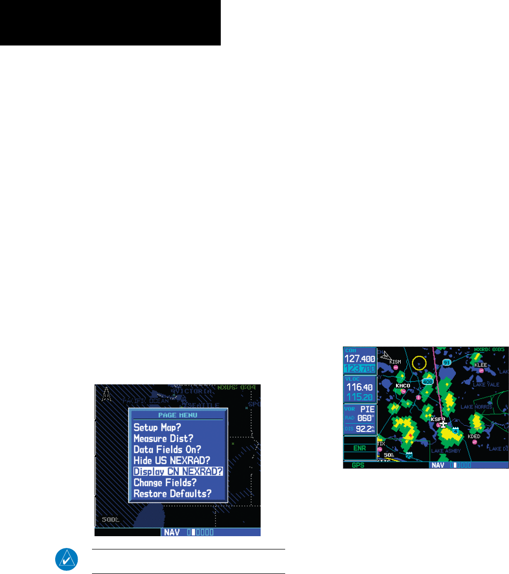
To display NEXRAD weather on the Map page:
1. With the Map page (second page of the NAV
page group) displayed, press the MENU key.
The Page Menu for the Map page appears.
NEXRAD is also available on the Nav 1 page
of the 500W series.
2. Turn the large right knob to highlight “Display
US NEXRAD?” or “Display CN NEXRAD?,” and
then press ENT. (If “Hide US NEXRAD?” or
“Hide CN NEXRAD?) appears, NEXRAD radar
data are already enabled; just press MENU
again to exit the Page Menu.)
NOTE: US and Canadian radar may not be displayed
simultaneously.
To display NEXRAD weather on the XM Weather
page:
1. With the XM Weather page (the third page of
the NAV page group) displayed, look at the
upper left corner of the page. Under the page
title (“XM Weather”) either “NEXRAD-US,”
“NEXRAD-CN,” or another weather product
appears. If the word is “NEXRAD-US” or
“NEXRAD-CN,” do nothing; NEXRAD weather
is already being displayed.
2. If the word in the upper left corner of the
page is another weather product (rather than
“NEXRAD-US” or “NEXRAD-CN”), press the
small right (CRSR) knob to highlight that
word. Then turn the small right knob to
change to “NEXRAD-US” or “NEXRAD-CN.”
3. Press the small right knob again to bring
down the cursor (that is, to stop the blinking
highlighting of “NEXRAD-US” or “NEXRAD-
CN”) and retain the selection.
NEXRAD U.S. and Canadian Coverage
SW Version 3.30 adds the ability to display
CanadianNEXRADonthemovingmappagesand
theXMWeatherpage.Thedisplayhasbeenmodied
tospecifywhethertheNEXRADdisplayedisU.S.or
Canadian.
190-00356-30 Rev F
15
Part Two: Section 2
XM Weather
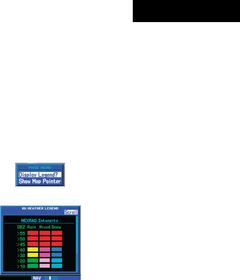
NEXRAD Intensity
ColorsareusedtoidentifythedifferentNEXRAD
echo intensities (reflectivity)measuredindBZ(deci-
belsofZ).“Reectivity”istheamountoftransmitted
power returned to the radarreceiver.Reectivity
(designatedbytheletterZ)coversawiderangeof
signals(fromveryweaktoverystrong).So,amore
convenient number for calculations and comparison, a
decibel(orlogarithmic)scale(dBZ),isused.ThedBZ
values increase as the strength of the signal returned
to the radar increases. There are seven gradations for
rain,twogradationsformixedrainandsnow,andtwo
gradations for snow.
To display the NEXRAD Intensity Legend:
1. While viewing the XM Weather page, press the
MENU key to display the Page Menu.
2. Turn the large or small knob to select “Display
legend?”
3. Press ENT to display the NEXRAD Intensity
Legend.
4. Turn the large or small knob to scroll through
the full table. Press CLR to return to the normal
view.
NEXRAD Abnormalities
There are possible abnormalities regarding dis-
playedNEXRADimages.Some,butnotall,causesof
abnormal displayed information include:
•GroundClutter
•Strobesandspuriousradardata
•Sunstrobes,whentheradarantenna points
directly at the sun
•Militaryaircraftdeploymetallicdustwhichcan
cause alterations in radar scans
•Interferencefrombuildingsormountains,
which may cause shadows
•Scheduledmaintenancemayputaradaroff-line
190-00356-30 Rev F
16
Part Two: Section 2
XM Weather
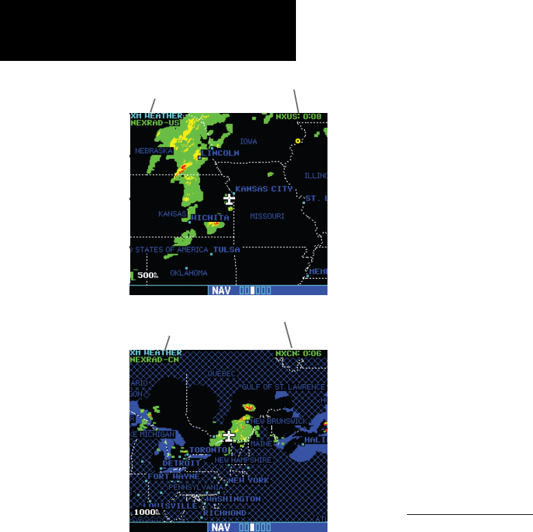
XM Weather Label and NEXRAD Source
U.S.
XM Weather Label and NEXRAD Source
Canada
NEXRAD Limitations
CertainlimitationsexistregardingtheNEXRAD
radar displays. Some, but not all, are listed for the
user’s awareness:
•NEXRADbasereectivity does not provide suf-
ficient information to determine cloud layers or
precipitation characteristics (hail vs. rain, etc).
• NEXRADbasereectivityissampledatthe
minimum antenna elevation angle. An indi-
vidualNEXRADsitecannotdepicthighaltitude
storms at close ranges, and has no information
about storms directly over the site.
• NeitherNEXRADweatherdatanortheageof
theNEXRADweatherdataaredisplayedata
zoomrangeoflessthan10NM.Theresolu-
tionofdisplayedNEXRADdatais2kilometers.
Therefore,whenzoomedinonthedisplay,
eachsquareblockis2kilometers.Theintensity
level reflected by the square will be the high-
estlevelsampledwithinthe2kilometersquare
area.
XM Weather METARs
XMWeatherMETARs(MeteorologicalAerodrome
Reports)areavailableontheXMWeatherpage.When
enabled(thatis,when“METAR”isshownintheupper
leftcornerofthepage),airportswithMETARinfor-
mationaboveacertainseveritylevelaremarkedwith
coloredagsonthedisplay.RefertotheXMWeather
legend for a description of the color code. The update
rate is every 12 minutes.
190-00356-30 Rev F
17
Part Two: Section 2
XM Weather
To display METARs on the XM Weather page:
1. While viewing the XM Weather page, check
the upper left corner to see whether “METAR”
or another weather product is displayed in the
upper left corner.
2. If another weather product (rather than
“METAR”) is shown, press the small right
(CRSR) knob to highlight the product name,
such as “NEXRAD”. Turn the small right knob
to change to “METAR,” and press that small
right knob again to bring down the cursor
(stop the highlighting) and retain the “METAR”
selection.
3. Now, colored flags will be displayed at those
airports that have METARs above a certain
severity level. (If there are no colored flags
visible, you may have to search a wider
area—zoom out with the RNG key—before
you see some METAR flags.)
To display the METAR Legend:
1. Press the MENU key to display the Page
Menu.
2. Turn the large or small right knob to select
“Display legend?”
3. Press ENT to display the METAR symbols
legend. Press the CLR key to remove the
METAR Symbols legend.
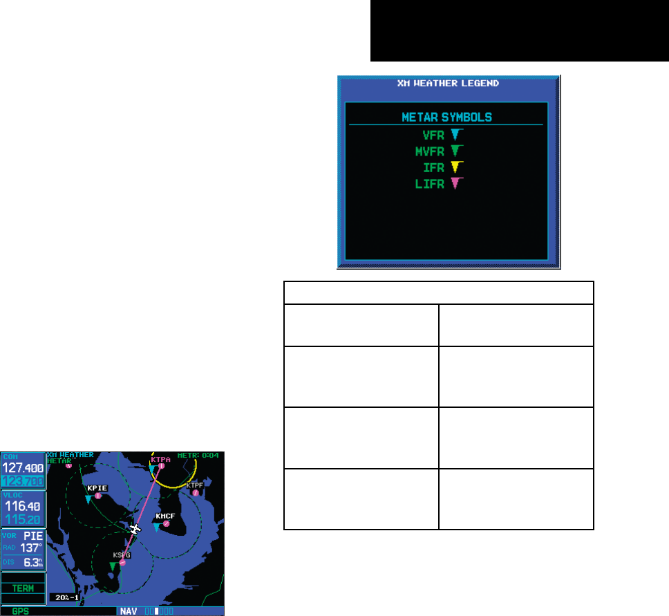
XM Weather METAR Symbols
VFR - Ceiling > 3000 ft and
visibility > 5 statute miles
Cyan
MVFR (Marginal VFR) - Ceil-
ing 1000 to 3000 ft, and/or
visibility 3 to 5 statute miles
Green
IFR - Ceiling 500 to 1000 ft,
and/or visibility 1 to 3
statute miles
Yellow
LIFR (Low IFR) - Ceiling less
than 500 ft and/or visibility
less than 1 statute mile
Magenta
Textual METAR Page
WhentheGDL69/69Aisinstalled,aTextual
METARpageisaddedamongtheAPT(airport)pages
of the WPT page group. This page can be accessed
fromtheXMWeatherpageaswellasfromtheWPT
page group.
To display Textual METARs from the Nav XM
Weather page:
1. While viewing the Nav XM Weather page, press
the MENU key to display the Page Menu.
2. Turn the large or small right knob to high-
light “Show Map Pointer?” and then press
ENT.
190-00356-30 Rev F
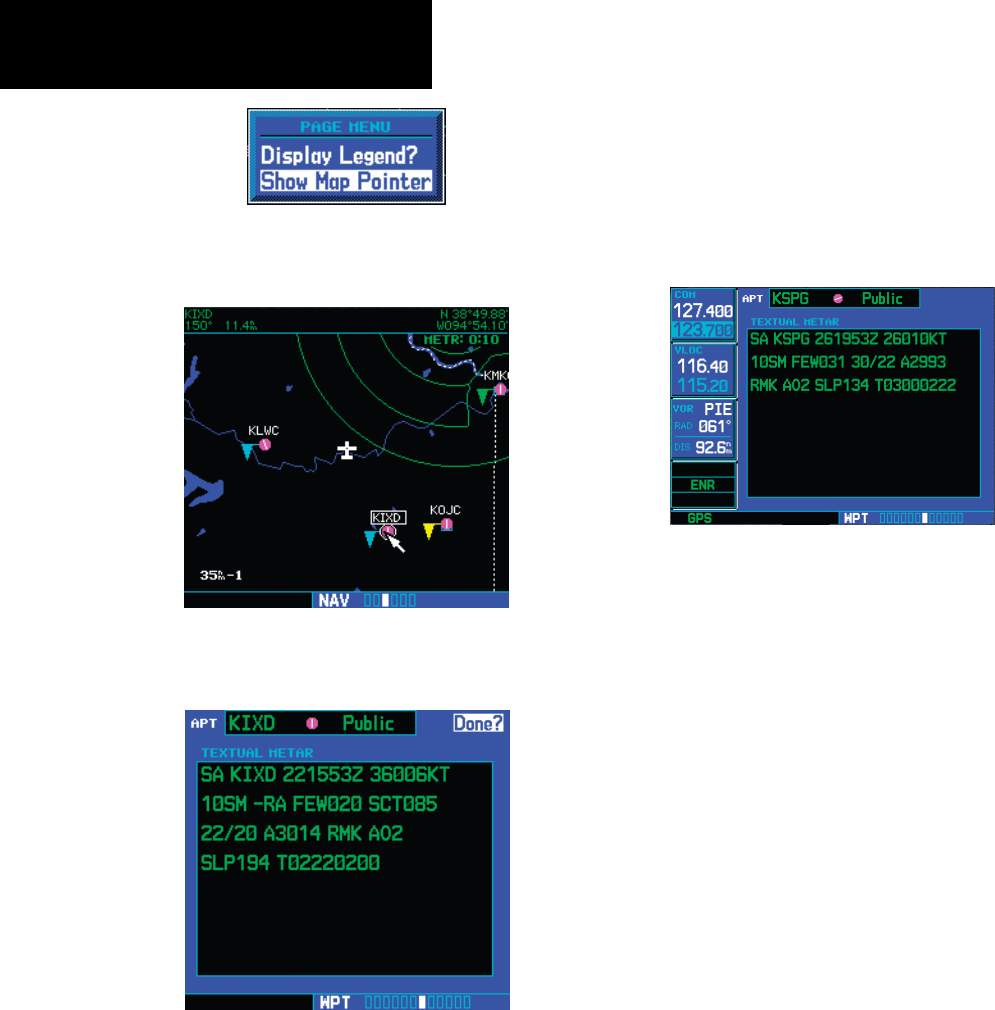
18
Part Two: Section 2
XM Weather
3. Turn the large or small right knob to move
the Map Pointer to highlight an airport with a
METAR flag.
4. Press ENT to display the METAR text. With
“Done?” highlighted, press ENT to return to
the map view.
To view any airport’s Textual METAR page:
1. If not viewing the WPT page group, press CLR
and turn the large right knob to select the
WPT page group.
2. Turn the small right knob until the Textual
METAR page appears.
3. To select another airport, press the small right
(CRSR) knob to highlight the airport ID (in the
“APT” field).
4. Turn the small and large right knobs to edit
the airport identifier for the desired airport.
Then, press ENT to confirm the airport name.
5. Press the small right (CRSR) knob again to
remove the cursor (that is, to stop highlighting
the APT field).
190-00356-30 Rev F
19
Part Two: Section 2
XM Weather
Textual METAR/TAF Code
ThecurrentairportweatherreportsontheTextual
METARpage(andtheairportweatherforecastsonthe
TAFpage,too)usearathercrypticformatoriginally
devisedforteleprinters.Youcanndinformation
aboutthisformatinanFAApublication,Aviation
WeatherFormats:METAR/TAF,whichcanbedown-
loadedfromtheFAAWebsite.
Youmayseethefollowingcodes,whichdiffer
slightlyfromthecodesdescribedintheFAApublica-
tionreferencedabove,atthestartofaMETARonthe
TextualMETARpage:
• SA=METAR—astandardhourlyMETAR
report.
• SP=SPECI—aSpecialReportinserted
betweenregularhourlyMETARstoprovide
late-breakingweathernews.
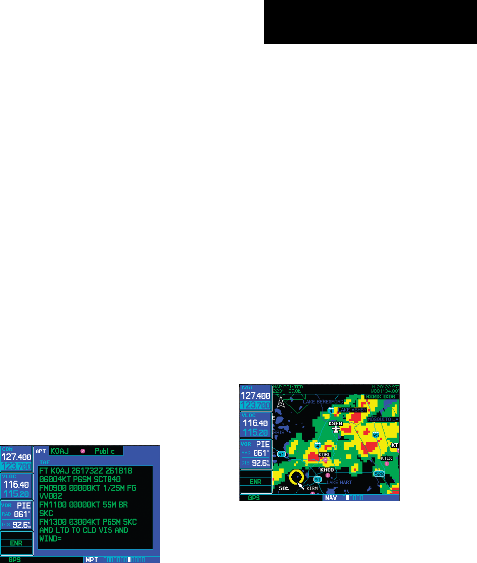
TAF Page
WhenaGDL69/69Aisinstalled,theTAF(Termi-
nalAerodromeForecast)pageisinsertedintotheWPT
pagegroup,immediatelyaftertheTextualMETAR
page.
Thispageshowsatextmessagegivingaweather
forecast for a particular airport. The format is similar
tothatusedforMETARS,butdescribesaweather
forecast rather than current weather at the particular
airport.
TFR Information
AreaswithTFRs(TemporaryFlightRestrictions)
are shown outlined in yellow on the NAV main page
ofthe500W-seriesandontheMapandXMWeather
pageofboththe400Wand500W-series.More
informationaboutTemporaryFlightRestrictionscan
beseenontheTFRInformationpage,whichcanbe
accessedfromtheMappageortheXMWeatherpage.
1a. With the Map page (the second page of the
NAV page group) displayed, press the small
right knob to bring up the map pointer.
or
1b. With the XM Weather page (the third page
of the NAV page group) displayed, press the
MENU key to bring up the Page Menu. Then,
turn the large right knob to highlight “Show
Map Pointer” and press ENT to bring up the
map pointer.
2. Turn the large and small right knobs to move
the map pointer to the yellow boundary of a
TFR region. When the map pointer is within
the TFR region, its boundary will be highlighted
with a wider yellow line.
190-00356-30 Rev F
20
XM Weather
Part Two: Section 2
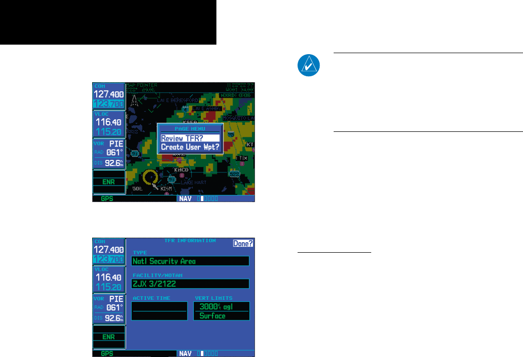
3. Press ENT. The first item is the pop-up Page
Menu will be “Review TFR?”.
4. Press ENT again to see the TFR Information
page.
5. Press ENT when done viewing the TFR Informa-
tion page.
TheeldsoftheTFRInformationpageareasfol-
lows:
• Type. A brief description of the reason for the
temporary flight restriction appears here. Some
examplesofthetextthatmightappearhere
are:“Fire,”“Miscellaneous,”“NationalSecurity
Area,”“NaturalDisaster,”and“SportsEvent.”
• Facility/NOTAM. This filed contains a code
forthenameoftheFAAfacilitythatissuedthe
NOTAM (Notice to Airmen) announcing the
TFR,followedbytheNOTAMnumber.For
instance,“ZSE6/9507”wouldmeanNOTAM
number6/9507fromtheSeattleARTCC(KZSE).
NOTE: The full text of the NOTAM may be obtained
from a local FSS or from the FAA web site, using the
contents of this field as a reference to locate the
particular NOTAM. However, the information shown on
the TFR Information page is sufficient to let you comply
with the Temporary Flight Restriction by avoiding the
affected area.
• Active Time. This field is for the beginning and
ending times of the temporary flight restriction.
Itmaybeblank,inwhichcasetheTFRisactive
“untilfurthernotice.”
• Vert Limits. This field gives the upper and
lowerlimitsoftheairspacetowhichtheTFR
applies.
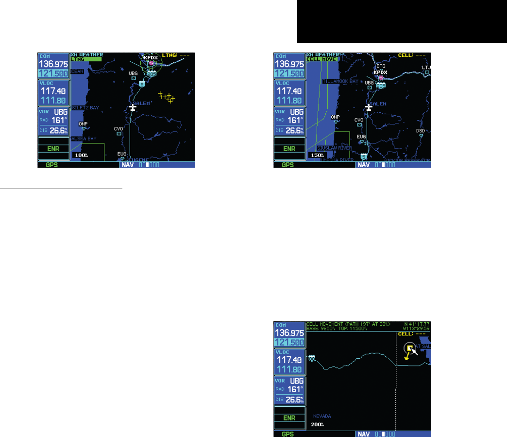
Lightning (LTNG)
Whenenabled,lightningstrikes and cells are
shown.Lightninginformationindicatesthelocationof
cloud-to-groundlightningstrikes.Lightningstrikesare
noted by yellow plus (+) signs.
To view XM Weather Lightning Strikes:
1. While viewing the XM Weather page, check
the upper left corner to see whether “LTNG”
or another weather product is displayed.
2. If another weather product (rather than
“LTNG”) is shown, press the small right
(CRSR) knob to highlight the product name,
such as “NEXRAD”. Turn the small right knob
to change to “LTNG,” and press that small
right knob again to bring down the cursor
(stop the highlighting) and retain the “LTNG”
selection.
190-00356-30 Rev F
21
Part Two: Section 2
XM Weather
Cell Movement (CELL MOVE)
When enabled, Cell Movement shows the storm
cells identified by the ground-based system. The
movement is depicted by an arrow. The tip of the
arrowrepresentswherethecellisexpectedtobein10
minutes from the time the cell location was deter-
mined.CellMovementisnotedbyayellowboxwith
an arrow showing reported the direction of travel.
To view XM Weather Cell Movement:
1. While viewing the XM Weather page, check the
upper left corner to see whether “CELL MOVE”
or another weather product is displayed.
2. If another weather product (rather than “CELL
MOVE”) is shown, press the small right
(CRSR) knob to highlight the product name,
such as “NEXRAD”. Turn the small right knob
to change to “CELL MOVE,” and press that
small right knob again to bring down the
cursor (stop the highlighting) and retain the
“CELL MOVE” selection.
To view XM Weather Cell Movement details:
1. While viewing the XM Weather page with Cell
Movement active, activate the Map Pointer by
pressing the MENU key, highlighting “Show
Map Pointer,” and press ENT.
2. Turn the large right knob to move the cursor
left and right. Turn the small right knob to
move the cursor up and down.
3. Move the cursor into the Cell Movement sym-
bol to vew details about the Cell.
190-00356-30 Rev F
22
Part Two: Section 3
XM Weather
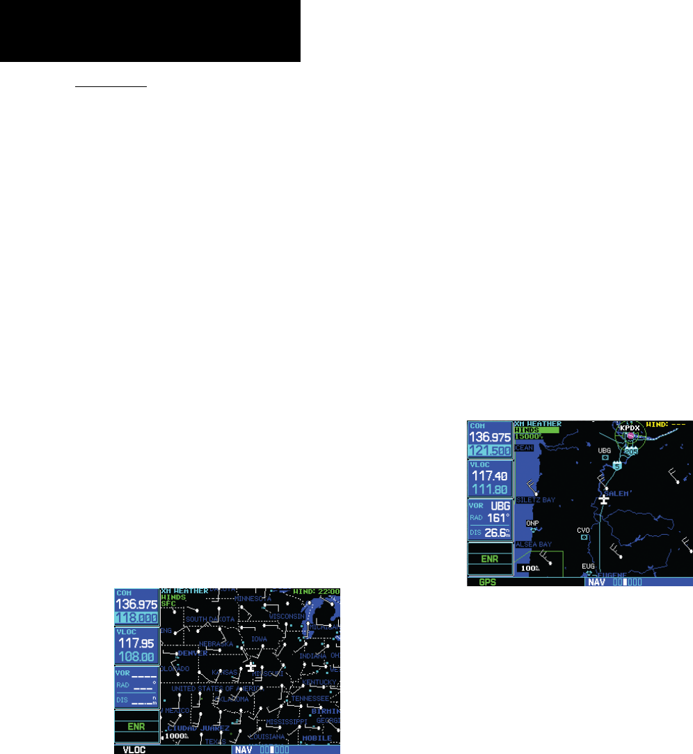
Winds Aloft
The Winds Aloft selection provides the pilot with
agraphicdisplayofpredictedwindsatanyoneof15
selectable altitudes. The winds at a given altitude are
selected in the Winds Aloft Alt selection. The selected
altitude is shown along with the product effective
time. Winds Aloft predictions are updated every hour
andaremadeavailableviatheGDL69/69Aatamore
frequent interval.
The display includes:
• Windbarbs,representingwindspeed,and
direction
• The selected altitude
• The effective time for the prediction.
Winds Aloft are represented by meteorological
symbolsknownas“windbarbs”.Awindbarbconsists
ofanarrow-likelinethatindicatesthedirectionin
whichthewindisblowing,withmarks(“barbs”)along
one side of the line to indicate wind speed. The barbed
end of the symbol points in the direction from which
thewindiscoming.Barbs,whichareusedsinglyand
in combinations, have the following values:
• Ashortline: 5knots
• Alongline: 10knots
• Apennant(triangle): 50knots
Forexample,averticallyorientedwindbarbwitha
pennant, two long lines and a short line at its upper end
woulddenotea75-knotwindblowingfromthenorth.
To view XM Weather Winds Aloft:
1. While viewing the XM Weather page, check the
upper left corner of the display. If a weather
product other than “WINDS” is shown, press
the small right (CRSR) knob to highlight the
product name. Turn the small right knob until
“WINDS” is displayed.
2. Turn the large right knob to move the cursor
down to the Altitude field, then use the small
right knob to select an altitude from ground
level up to 42,000 feet (in 3,000-foot incre-
ments). Note that you can move up and down
the atmosphere, comparing wind predictions
at different altitudes.
3. When done, press the small right (CRSR)
knob again to remove the cursor (remove
highlighting from the altitude field).
190-00356-30 Rev F
23
Winds Aloft Altitude
The Winds Aloft Altitude selection provides the
pilot with the ability to select any wind altitude from
the ground up to 42,000 feet in 3,000 foot increments.
When no data are shown at a given altitude, the data
for that altitude has not been received. Wait for the
nextupdate.Theselectedaltitudeisdepictedbelow
theWINDSlabel.
To change the XM Weather Winds Aloft altitude:
1. With the “WINDS” product selected, turn the
large right knob to highlight the altitude
value.
2. Turn the small right knob to change the
value.
3. When done, press the small right (CRSR)
knob again to remove the cursor (remove
highlighting from the altitude field).
Section 3: XM AUX Pages
WhenaGDL69(orGDL69A)isinstalled,three
(orfour)pagesareinsertedintothe500W/500W’s
AUXpagegroup.Herewediscussthetwopagesthat
areinsertedregardlessofwhethertheXMreceiverisa
GDL69orGDL69A:
• XM Information Page. This page contains
information that you will use when activating
yourXMsatelliteradiosubscription.
• XM Weather Timestamp Pages. These pages
show timestamp data for the most recently
receivedXMweatherdata.
TheotherAUXpage,whichisinstalledonlyifthe
XMreceiverisaGDL69A,istheXMaudiopage.
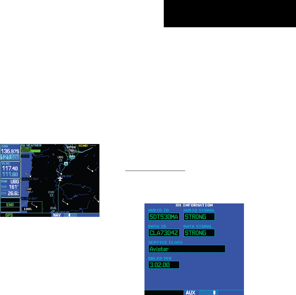
XM Information Page
TheXMInformationpageintheAUXpagegroup
is the page you will refer to when activating your sub-
scriptiontotheXMSatelliteRadioservices.
• AudioID.TheAudioIDcontainstheeight-
characteridenticationcodeoftheXMAudio
radiobuiltintotheGDL69A.ProvidethisID
toXMSatelliteRadiowhenactivatinganXM
audiosubscription.(InthecaseofaGDL69,
this field shows eight hyphens instead of an
Part Two: Section 3
XM Aux Pages
190-00356-30 Rev F
24
audioID,becausetheGDL69isadata-only
receiver.)
• Audio Signal. The Audio Signal field indicates
thesignalstrengthoftheGDL69A’saudio
signal.(InthecaseofaGDL69,thiseldshows
“antenna”ratherthanasignalstrengthindica-
tion.)
• Data ID.TheDataIDeldcontainstheeight-
characterIDcodeoftheXMdataradiobuilt
intotheGDL69orGDL69A.ProvidethisID
toXMSatelliteRadiowhenactivatingyourXM
aviation data subscription.
• Data Signal.TheDataSignalelddisplaysan
indicationoftheXMdatasignalstrength.
• Service Class. Once you have activated your
XMSatelliteRadioservice,theServiceClass
eldwillshowtheXMsubscriptionplanyou
havepurchased.Typicalvalueswouldbe“Avia-
torLT”or“Aviator.”Currently,the400Wand
500W-seriesonlysupportasubsetoftheAvia-
torLTservicefromXMSatelliteRadio.
Product Aviator LT Aviator
US NEXRAD • •
CN NEXRAD •
Radar Coverage • •
Precipitation Type
(at surface)
• •
TFRs • •
US METARs • •
US TAFs • •
US Winds Aloft •
Cell Movement •
Lightning •
NOTE: If an unrecognized service class is detected,
“Activated” will be displayed along with a service class
code.
• GDL 69 Version. This field shows the version
numberofthesoftwareinyourGDL69orGDL
69AXMradioreceiver.
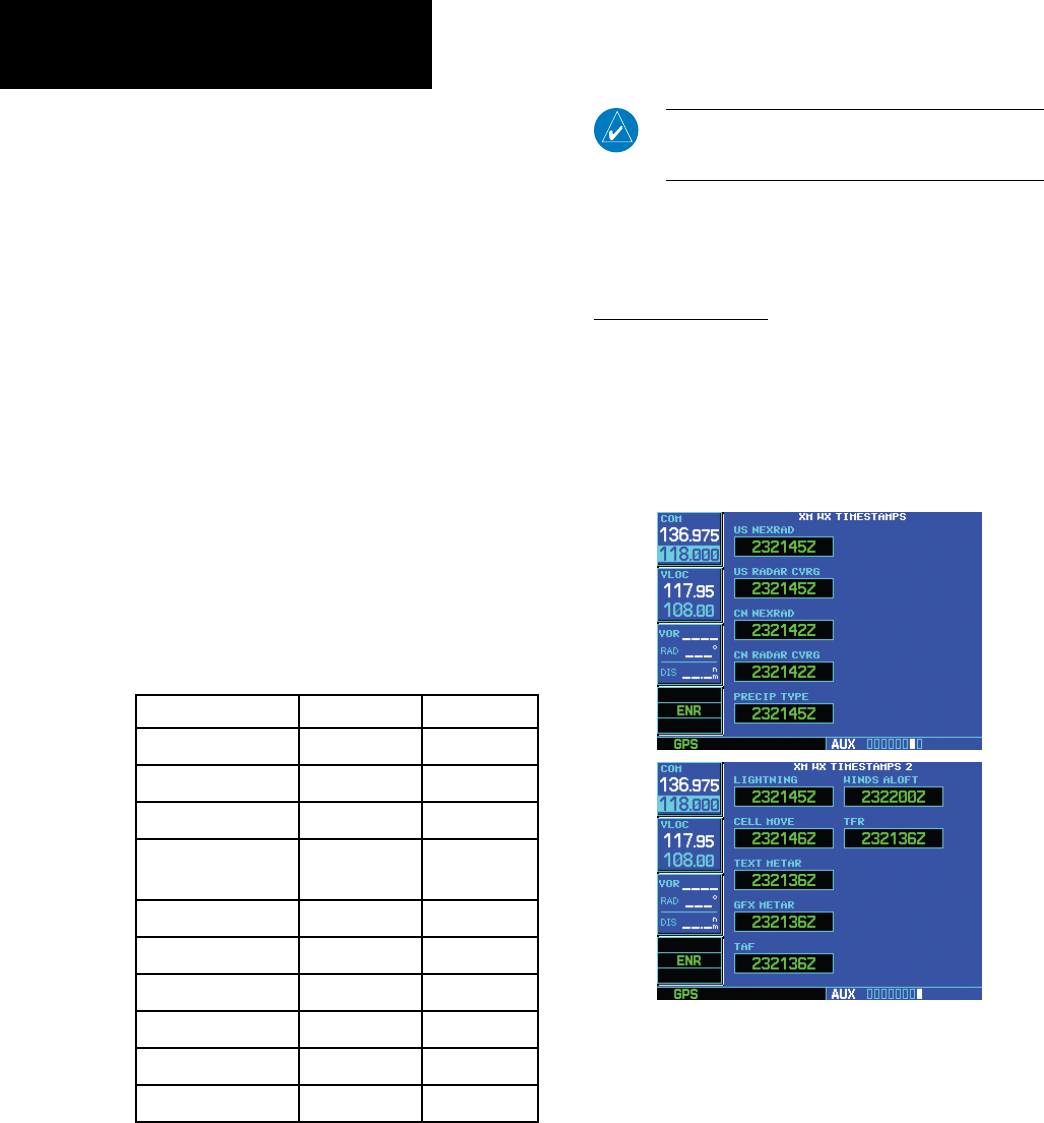
XM WX Timestamps
TheXMWXTimestamppages,liketheXM
Informationpage,isaddedtothe400W/500W’sAUX
pagegroupwhenaGDL69/69Aisinstalled.These
pages display date/time stamps showing when the
variousitemsofXMweatherdataweremostrecently
downloaded.
Part Two: Section 4
XM Audio
190-00356-30 Rev F
25
Each of these time stamps is a date-time group in
“DDHHMMZ”format,where:
• DD is the day of the month
• HH is the hour of the day
• MM is the minute of the hour
• Zisatimezonedesignatorindicatingthatthe
date and time are for standard time on the
Greenwichmeridian:thatis,UTC(Coordi-
natedUniversalTime).
Section 4: XM Audio
AudioentertainmentisavailablethroughtheXM
SatelliteRadioServicewhenactivatedintheoptional
installationoftheGDL69A.The400Wand500W
series units serve as the display and control head for
yourremotelymountedGDL69A.XMSatelliteRadio
allowsyoutoenjoyavarietyofradioprogramming
over long distances without having to constantly
searchfornewstations.Basedonsignalfromsatellites,
coveragefarexceedsland-basedtransmissions.When
enabled,theXMSatelliteRadioaudioentertainmentis
accessibleintheAUXfunction.
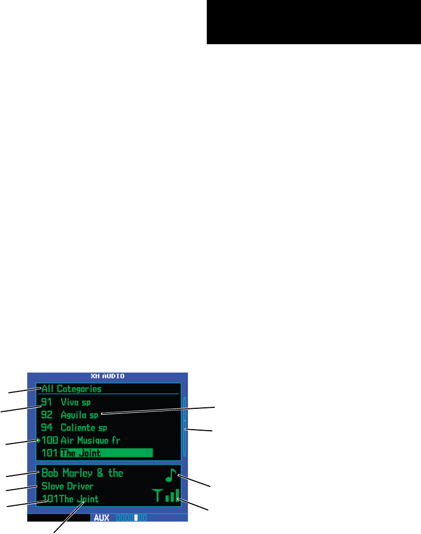
TheinformationontheXMSatelliteRadiodisplay
is composed of four areas: the Active channel, avail-
able Channels, Category of the highlighted channel,
and the Volume setting. The Active Channel window
shows the Channel Name and Number, Artist, Song
Title, Category, and provides an indication of signal
strength.Abargraphnexttotheantennasymbol
describesthesignalstrength.Maximumsignalstrength
is shown by three full bars.
Part Two: Section 4
XM Audio
Category name
Song title Audio output (enabled or disabled)
Slider
Channel Name
Signal strength
indicator
Artist name
Channel
number
Pointer showing
current selection
being played
Channel name
XM Audio Page Description
Channel
number
190-00356-30 Rev F
26
TheXMAudiopageallowsyoutocontrolthe
functionsoftheXMAudioreceiverintheGDL69A,
such as, category and channel selection, artist
selection, and volume. Pressing the MENUkey
displays the Page Menu selections.
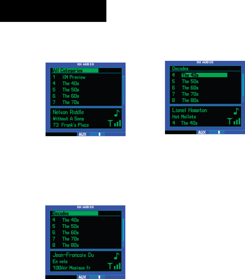
Selecting categories
1. Press the small right (CRSR) knob to high-
light the category names. The categories will
be listed below in numeric order.
2. Turn the small right knob to scroll through
the list of categories. Categories are shown in
the upper section of the display. The channels
for each category are shown in the list below
the category title.
3. Press ENT to select the highlighted category.
The first channel in the selected category will
now be highlighted and the current song being
played in that channel will be shown in the
lower window.
4. Turn the large right knob counterclockwise
to move the highlight back up to the cat-
egory name window.
Selecting channels
1. Press the small right (CRSR) knob to high-
light the category names.
2. Turn the large right knob clockwise, or press
ENT, to move the highlight into the channel
selections.
3. Turn the small right knob to highlight a chan-
nel.
4. Press ENT to select the highlighted channel
for listening. A triangle will point to the song
currently being played.
Part Two: Section 4
XM Audio
190-00356-30 Rev F
27
Part Two: Section 4
XM Audio
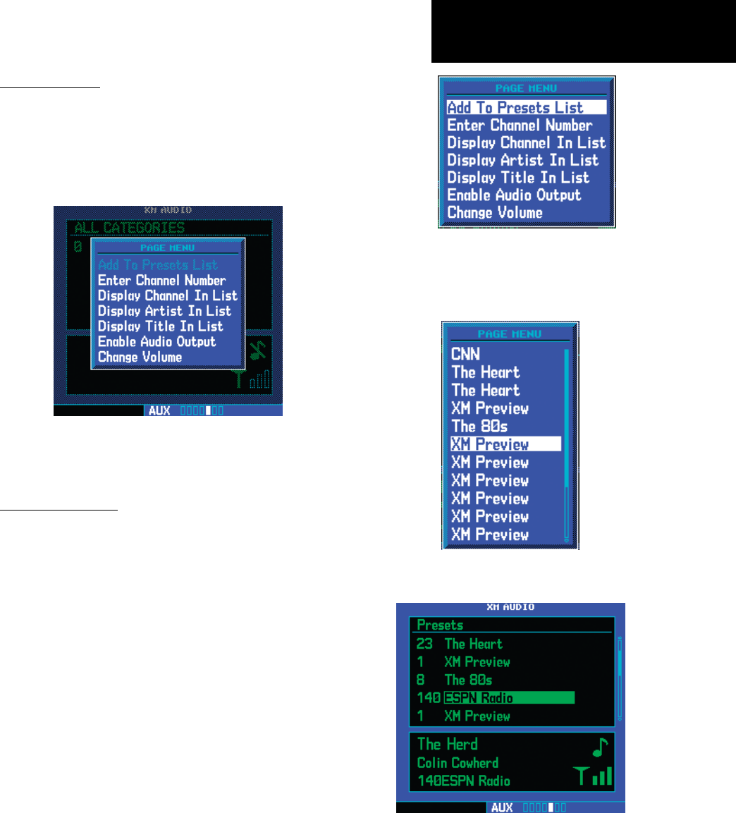
XM Audio Menu
TheXMAudioMenuprovideschoicesforselecting
a channel, displaying the channel, artist, or title,
enabling audio output, and controlling the volume.
1. While viewing the XM Audio page, press the
MENU key.
2. Turn the large or small right knobs to high-
light the choices. Press the ENT key to make a
selection.
Add to Presets List
Uptofteenchannelsmaybesavedaspresetsto
easily return to your favorite channels.
1. While viewing the XM Audio page, selected
the desired channel.
2. While the desired channel is highlighted, press
the MENU key. With “Add to Presets List?”
highlighted, press ENT.
3. Turn the large right knob clockwise to move
the highlight into the presets list. Turn the
small right knob to highlight the position
where you want to place the preset.
4. Press ENT to replace the previous preset chan-
nel with the newly selected channel.
190-00356-30 Rev F
28
Part Two: Section 4
XM Audio
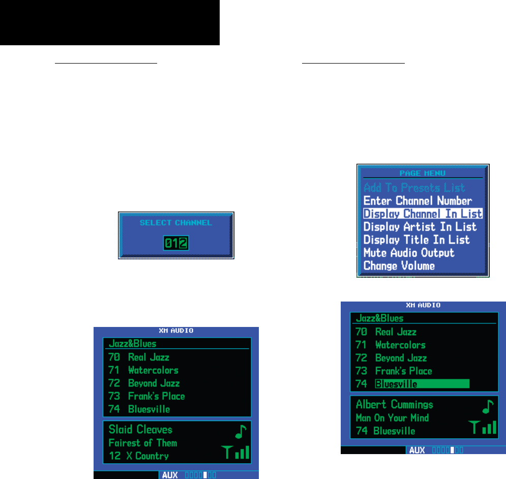
Enter Channel Number
Youmaydirectlyselectaspecicchannelbyusing
the“EnterChannelNumber”itemfromthePage
Menu.
1. While viewing the XM Audio page, press the
MENU key. Turn the large right knob to
highlight “Enter Channel Number.”
2. Turn the large right knob to move the
highlight and the small right knob to select
a number.
3. Press the ENT key to make a selection. The
selected channel will now play and is dis-
played in the window at the bottom of the
display.
Display Channel In List
Channels can be shown in a list of channels in the
middlepanebyusingthe“DisplayChannelInList”
item from the Page Menu.
1. While viewing the XM Audio page, press the
MENU key. Turn the large right knob to
highlight “Display Channel In List.”
2. Press the ENT key.
190-00356-30 Rev F
29
Part Two: Section 4
XM Audio
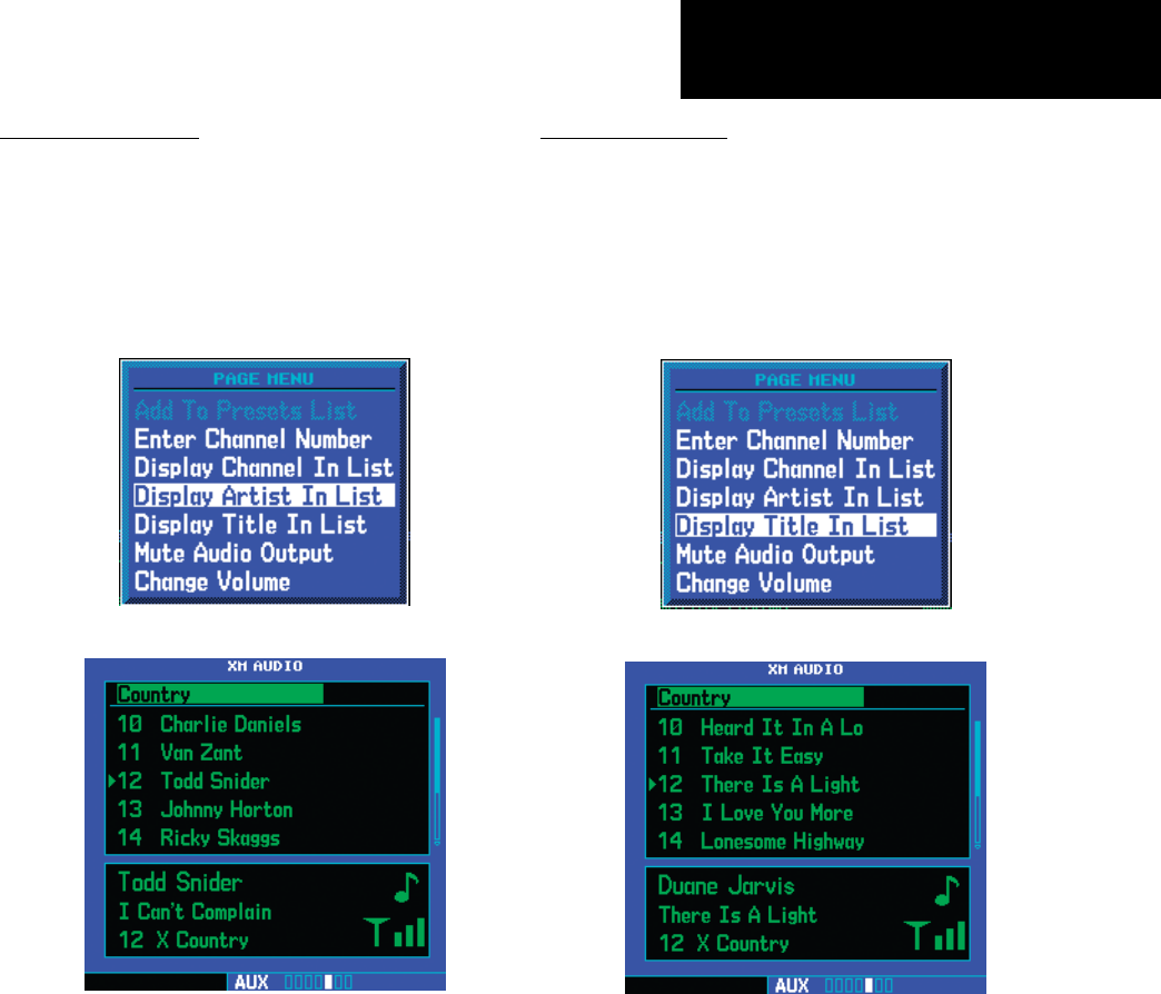
Display Artist In List
The name of the artists in the range of displayed
channels can be shown in the middle pane by using
the“DisplayArtistInList”itemfromthePageMenu.
1. While viewing the XM Audio page, press the
MENU key. Turn the large right knob to
highlight “Display Artist In List.”
2. Press the ENT key.
Display Title In List
The Titles of the songs in the range of displayed
channels can be shown in the middle pane by using
the“DisplayTitleInList”itemfromthePageMenu.
1. While viewing the XM Audio page, press the
MENU key. Turn the large right knob to
highlight “Display Title In List.”
2. Press the ENT key.
190-00356-30 Rev F
30
Part Two: Section 4
XM Audio
Enable/Mute Audio Output
The Enable/Mute Audio Output selection of the
Page Menu allows you to toggle the audio output On
or Off. When Audio Output is muted, a green slash
will cross over the music symbol in the song pane.
1. While viewing the XM Audio page, press the
MENU key. Turn the large right knob to
highlight “Enable Audio Output” or “Disable
Audio Output.”
2. Press the ENT key to perform the highlighted
action. Pressing the CLR key toggles the
audio output.
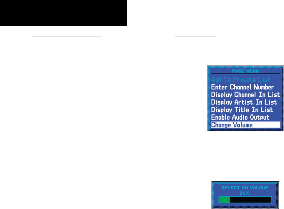
Change Volume
TheXMAudiovolumemaybechangedintwo
ways: directly with the Rangekeysorthroughthe
Page Menu.
1. While viewing the XM Audio page, press the
MENU key. Turn the large right knob to
highlight “Change Volume.”
2a. Press the ENT key and then turn the small
right knob to change the volume.
or
2b. Press the Range keys to adjust the volume.
Blank Page
190-00356-30 Rev F
31
Part Three: Section 1
TAWS Introduction
Part Three:
TAWS Interface
Section 1: Introduction
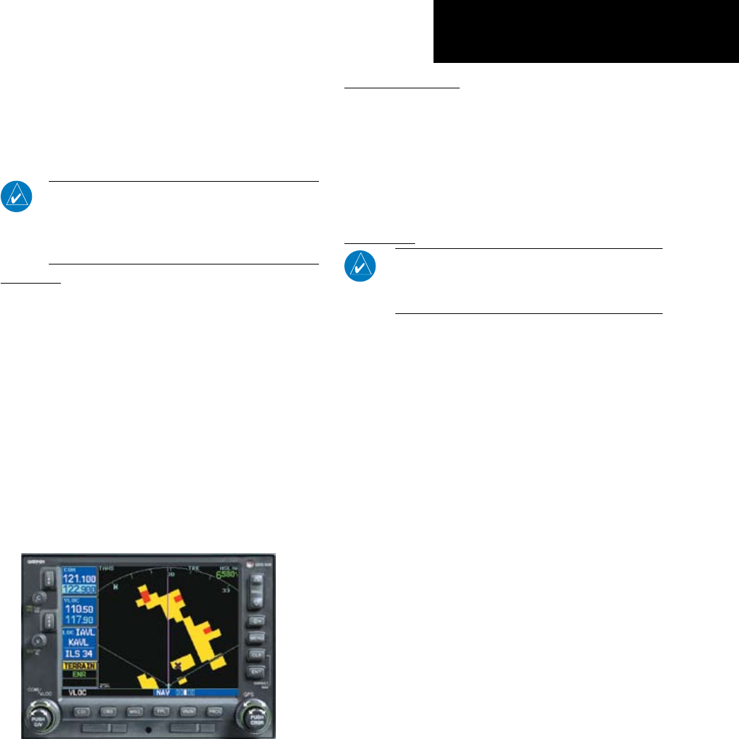
NOTE: GNS 530W units may display a TERRAIN
Page, a TAWS Page, or neither, (but not both)
depending upon the installed hardware and
configuration.
Overview
Garmin’s Terrain Awareness Warning System
(TAWS)isanoptionalfeature(500W-seriesonly)to
increase situational awareness and aid in reducing
controlled flight into terrain. Garmin TAWS satisfies
TSO-C151bClassBrequirementsforcertication.
ClassBTAWSisrequiredforallPart91aircraft
operationswithsixormorepassengerseatsandfor
Part135turbineaircraftoperationswithsixtonine
passengerseats(FARParts91.223,135.154).
TAWS provides visual and aural annunciations
when terrain and obstacles are within the given altitude
threshold from the aircraft.
Garmin TAWS satisfies TSO-C151b Class B
requirements for certification
Operating Criteria
Garmin TAWS requires the following to operate
properly:
•Thesystemmusthaveavalid3DGPSposition
solution
•Thesystemmusthaveavalidterrain/obstacle/
airport terrain database
Limitations
NOTE: The data contained in the TAWS databases
comes from government agencies. Garmin accurately
processes and cross-validates the data, but cannot
guarantee the accuracy and completeness of the data.
TAWS displays terrain and obstructions relative
to the altitude of the aircraft. The displayed alerts
and warnings are advisory in nature only. Individual
obstructions may be shown if available in the database.
However,allobstructionsmaynotbeavailableinthe
database and data may be inaccurate. Never use this
information for navigation or to maneuver to avoid
obstacles.
Terrain information is based on terrain elevation
data contained in a database that may contain
inaccuracies. Terrain information should be used
as an aid to situational awareness. Never use it for
navigation or to maneuver to avoid terrain.
TAWS uses terrain and obstacle information sup-
plied by government sources. The data undergoes veri-
fication by Garmin to confirm accuracy of the content,
perTSO-C151b.However,thedisplayedinformation
should never be understood as being all-inclusive.
190-00356-30 Rev F
32
Part Three: Section 1
TAWS Operation
Section 2: TAWS Operation
TAWS Alerting
TAWS uses information provided from the GPS
receivertoprovideahorizontalpositionandaltitude.
GPS altitude is derived from satellite measurements.
GPSaltitudeisconvertedtoameansealevel(MSL)-
basedaltitude(GPS-MSLaltitude)andisusedto
determineTAWSalerts.GPS-MSLaltitudeaccuracyis
affected by factors such as satellite geometry, but it is
notsubjecttovariationsinpressureandtemperature
that normally affect pressure altitude devices. GPS-
MSLaltitudedoesnotrequirelocalaltimetersettings
todetermineMSLaltitude.Therefore,GPSaltitude
providesahighlyaccurateandreliableMSLaltitude
source to calculate terrain and obstacle alerts.
TAWS utilizes terrain and obstacle databases that
arereferencedtomeansealevel(MSL).UsingtheGPS
positionandGPS-MSLaltitude,TAWSdisplaysa2-D
picture of the surrounding terrain and obstacles relative
tothepositionandaltitudeoftheaircraft.Furthermore,
the GPS position and GPS-MSL altitude are used to
calculate and “predict” the aircraft’s ight path in
relation to the surrounding terrain and obstacles. In this
manner, TAWS can provide advanced alerts of predicted
dangerousterrainconditions.Detailedalertmodesare
described later in this section.
Baro-Corrected Altitude
Baro-correctedaltitude(orindicatedaltitude)isde-
rivedbyadjustingthealtimetersettingforlocalatmo-
spheric conditions. The most accurate baro-corrected
altitude can be achieved by frequently updating the
altimeter setting to the nearest reporting station along
theightpath.However,becauseactualatmosphere
conditions seldom match the standard conditions
defined by the International Standard Atmosphere
(ISA) model (where pressure, temperature, and lapse
rateshavexedvalues),itiscommonforthebaro-cor-
rected altitude (as read from the altimeter) to differ
fromtheGPS-MSLaltitude.Thisvariationresultsin
the aircraft’s true altitude differing from the baro-cor-
rected altitude.
Power Up
Duringpower-upofthe500WSeriesunit,the
terrain/obstacle database versions are displayed along
with a disclaimer to the pilot. At the same time,
TAWS self-test begins. TAWS gives the following aural
messages upon test completion:
•“TAWS System Test, OK”, if the system passes the test
•“TAWS System Failure”, if the system fails the test
A test failure is also annunciated for TAWS, as
shown in the TAWS Alert Summary table.
TAWS Page
The TAWS Page is in the NAV group of pages (see
the500WSeriesPilot’sGuidefordetailedinformation
regarding page groups and pages).
The TAWS Page
190-00356-30 Rev F
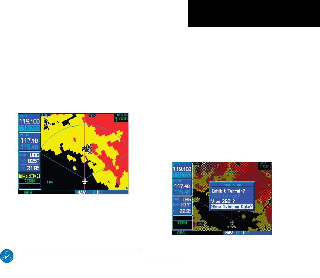
33
Part Three: Section 2
TAWS Operation
To display the TAWS Page, select the NAV group
and turn the small right knobuntiltheTAWSPage
is displayed. Terrain information, aircraft ground
track,andGPS-derivedMSLaltitudearedisplayed
on the page. Altitude is shown in increments of 20
feet or in increments of 10 meters, depending on unit
conguration.The“G”torightoftheMSLaltitude
display reminds the pilot that altitude is GPS-derived.
The TAWS Page has two selectable view settings:
120˚ Viewing Angle on the TAWS Page
•360˚View—Viewfromaboveaircraftdepicting
surrounding terrain on all sides
•120˚View—Viewofterrainaheadofand60˚to
either side of the aircraft flight path
NOTE: The TAWS Page gives a “Track Up” display
orientation, as indicated by the “TRK” label shown on
the display. This is the only orientation available for the
TAWS Page.
To display a 120˚ view:
1. Select the TAWS Page and press MENU. Select
“View 120˚?”.
2. Press ENT. The TAWS Page displays the 120˚
view. To change to a 360˚ view, repeat step 1,
select “View 360˚?”, and press ENT.
Seven display ranges are available, allowing for a
more complete view of the surrounding area.
To change the display range:
1. Select the TAWS Page and press up or down
on the RNG key to select the desired range:
1 NM, 2 NM, 5 NM, 10 NM, 25 NM, 50 NM,
100 NM.
Aviationinformationsuchasairports,VORs,and
other navaids can be turned on or off on the TAWS
Page.
To show or hide aviation information:
1. Press MENU.
2. Select “Show (or Hide) Aviation Data?” and
press ENT. Pressing the CLR key when the
TAWS Page is displayed can also be used to
toggle aviation information on or off.
Aviation Data
Inhibit Mode
TAWSprovidesan“inhibitmode”.Thismodeis
designedtodeactivatePDA/FLTAauralandvisual
alerts when they are deemed unnecessary by the
aircrew.FlyingVFRintoanareawhereuniqueterrain
existscouldcausethesystemtoannunciateanuisance
alert. Pilots should use discretion when inhibiting
the TAWS system and always remember to enable the
systemwhenappropriate.OnlythePDAandFLTA
alerts are disabled in the inhibit mode. See section 3
for more information on TAWS alerts.
190-00356-30 Rev F
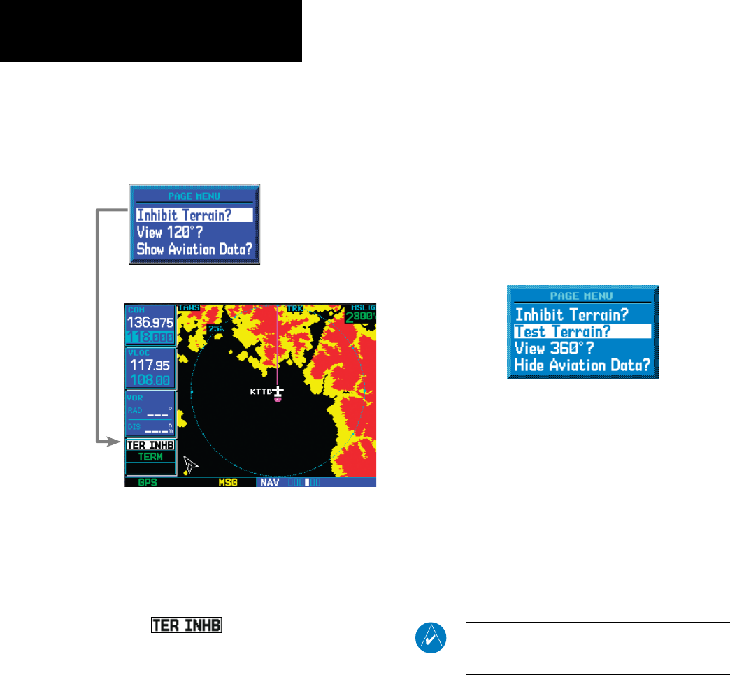
34
Part Three: Section 2
TAWS Operation
TERRAINconguredunitswillrestorethe“inhibit
state”atstartuptothelastpilot-selectedsetting.TAWS
configured units will always start up with TAWS alerts
uninhibited.
Inhibiting Terrain
To inhibit PDA and FLTA alerts:
1. Select the TAWS Page and press MENU.
“Inhibit Terrain?” is selected by default.
2. Press ENT. The PDA/FLTA alerts are inhibited.
The annunciation is displayed in
the terrain annunciator field whenever terrain
is inhibited.
To enable PDA and FLTA alerts:
1. Select the TAWS Page and press MENU.
“Enable Terrain?” is selected by default.
2. Press ENT. The PDA/FLTA alerts are functional
again.
External TAWS Inhibit Control
An optional installation is allowed for providing
anexternalTAWSInhibitswitch.Pressingtheexternal
TAWS Inhibit switch toggles the TAWS inhibit on and
off in the same manner as using the Page Menu selec-
tion.
TAWS Manual Test
Garmin TAWS provides a manual test capability
which verifies the proper operation of the aural and
visual annunciations of the system prior to a flight.
“Test Terrain” selection
To manually test the TAWS system:
1. Select the TAWS Page and press MENU.
2. Select the “Test Terrain?” option.
3. Press ENT to confirm the selection.
An aural message is played giving the test results:
•“TAWS System Test, OK”ifthesystempassesthe
test
•“TAWS System Failure”ifthesystemfailthetest
NOTE: TAWS System Testing is disabled when
ground speed exceeds 30 knots so as not to
impede TAWS alerting.
190-00356-30 Rev F
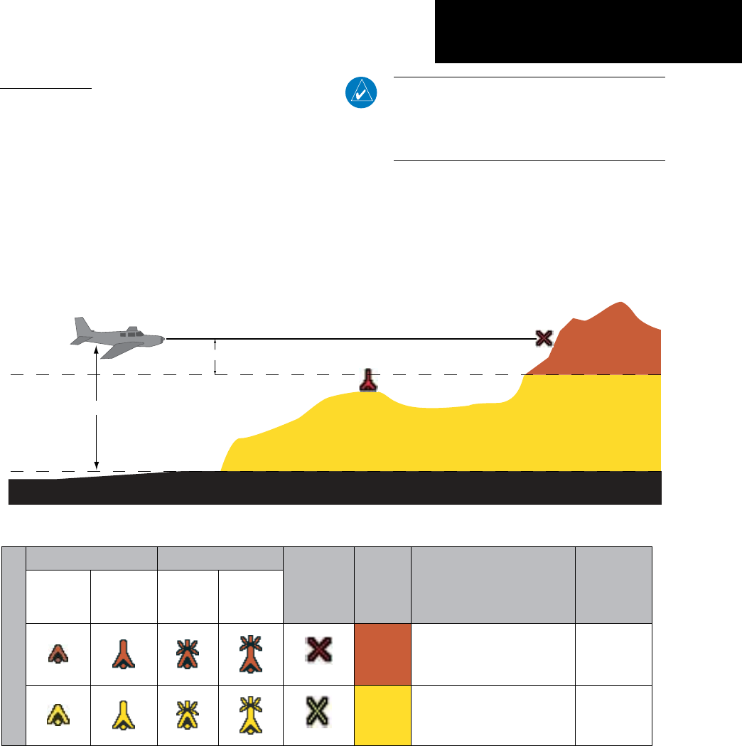
35
Part Three: Section 2
TAWS Operation
TAWS Symbols
The symbols and colors in the following figure and
table are used to represent obstacles and potential impact
points on the TAWS Page. TAWS uses yellow (caution)
and red (warning) to depict terrain information relative
to aircraft altitude. Each color is associated with an alert
severity level. Terrain graphics and visual annunciations
also use these color assignments.
Note that obstacle symbols are shown on display
zoomrangesupto10NM.
Potential Impact Point
Unlighted Obstacle
Projected Flight Path
1000 ft
100 ft Threshold
Terrain more than 1000 ft below the aircraft altitude (Black)
Terrain between 100 ft and 1000 ft below the
aircraft altitude (Yellow)
Terrain above or
within 100 ft
below the aircraft
altitude (Red)
Terrain Altitude/Color Correlation for Terrain Proximity
Unlighted Obstacle Lighted Obstacle Potential
Impact
Points
Terrain
Color Terrain/Obstacle Location Alert Level
< 1000 ft
AGL
> 1000 ft
AGL
< 1000 ft
AGL
> 1000 ft
AGL
Obstacle Symbol
Red
Terrain/Obstacle at or within
100 ft below current aircraft
altitude
WARNING
(Red)
Yellow
Terrain/Obstacle between
100 ft and 1000 ft below
current aircraft altitude
CAUTION
(Yellow)
TAWS Terrain/Obstacle Colors and Symbology
NOTE: If an obstacle and the projected flight
path of the aircraft intersect, the display auto-
matically zooms in to the closest potential point
of impact on the TERRAIN Page.
190-00356-30 Rev F
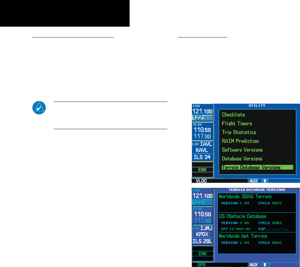
36
Part Three: Section 2
TAWS Operation
General Database Information
Garmin TAWS uses terrain and obstacle informa-
tion supplied by government sources. The data under-
goes verification by Garmin to confirm accuracy of
thecontent,perTSO-C151b.However, the displayed
information should never be understood as being
all-inclusive. Pilots must familiarize themselves
with the appropriate charts for safe flight.
NOTE: The data contained in the terrain and obstacle
databases comes from government agencies. Garmin accu-
rately processes and cross-validates the data, but cannot
guarantee the accuracy and completeness of the data.
The terrain/obstacle databases are contained on a
datacard which is inserted in the right-most slot of the
400W/500WSeriesunits.
Database Versions
The version and area of coverage of each ter-
rain/obstacledatabaseisshownontheTerrainData-
baseVersionsPage,locatedintheAUXPageGroup.
Databasesarecheckedforintegrityatpower-up.Ifa
database is found to be missing and/or deficient, the
TAWS system fails the self-test and displays the TAWS
system failure message.
Terrain Database Information
190-00356-30 Rev F
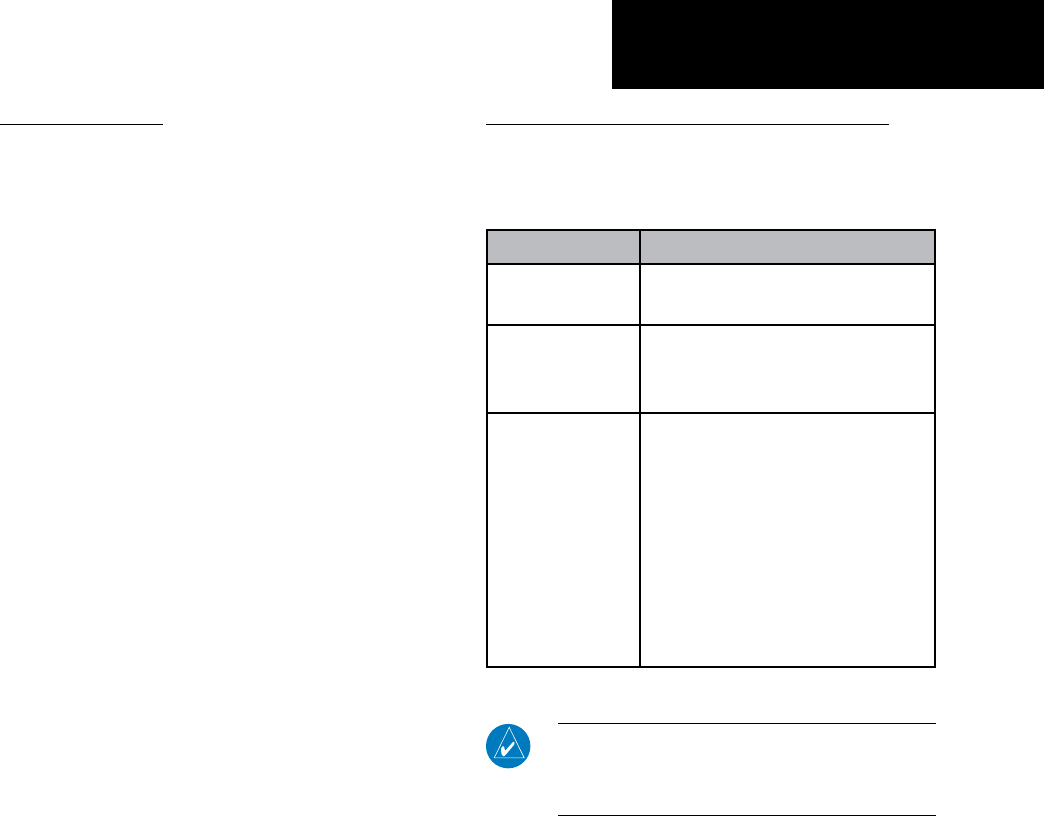
37
Part Three: Section 2
TAWS Operation
Database Updates
Terrain/obstacle databases are updated periodi-
cally with the latest terrain and obstacle data. Visit the
Garminwebsitetocheckfornewerversionsofterrain/
obstacle databases. Compare database cycle numbers
to determine if a newer version is available.
The database update process includes either
reprogramming or replacing the database card and
inserting the updated card in the right card slot on the
unit front panel. The terrain/obstacle database may
be downloaded via the internet and the card repro-
grammedusingaUSBprogrammeravailablefrom
Garmin.ContactGarminat800-800-1020orat
www.garmin.com for more information.
To update your terrain/obstacle databases:
1. Acquire a new terrain data card from
Garmin.
2. Turn off the power to the 500W Series unit.
3. Remove the old terrain data card and insert the
new card into the right-most slot of the 500W
Series unit.
4. Turn on the 500W Series unit and verify that
the TAWS system passes self-test.
Terrain/Obstacle Database Areas of Coverage
The following describes the area of coverage avail-
ableineachdatabase.Regionaldenitionsmaychange
without notice.
Database Coverage Area
Worldwide (WW) Latitudes: N75° to S60°
Longitudes: W180° to E180°
United States (US)
Limited to the United States plus
some areas of Canada, Mexico,
Caribbean, and the Pacific.
US/Europe
Alaska, Austria, Belgium, Canada*,
Caribbean*, Czech Republic,
Denmark, Estonia, Finland, France,
Germany, Greece, Hawaii, Iceland,
Ireland, Italy, Latvia, Lithuania,
Mexico*, Netherlands, Norway,
Poland, Portugal, Slovakia, Spain,
Sweden, Switzerland, United
Kingdom, United States
* Indicates partial coverage
NOTE: Obstacles 200 feet and higher are included in
the Obstacle Database. It is very important to note that
not all obstacles are necessarily charted and therefore
may not be contained in the Obstacle Database.
190-00356-30 Rev F
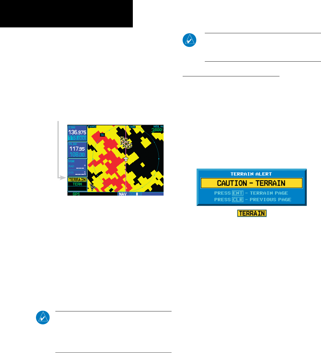
38
Part Three: Section 2
TAWS Alerts
Section 3: TAWS Alerts
Alerts are issued when flight conditions meet
parameters that are set within TAWS software
algorithms. TAWS alerts typically employ either a
CAUTION or a WARNING alert severity level, or
both. When an alert is issued, visual annunciations
are displayed. Aural alerts are simultaneously issued.
Annunciations appear in a dedicated field in the lower
left corner of the display.
TAWS Annunciation Field
TAWS Annunciation Field
Annunciations are color-coded according to the
TAWS Alert Summary table. Pop-up terrain alerts can
also appear during an alert, but only when the TAWS
Page is not displayed. There are two options when
an alert is displayed:
To acknowledge the pop-up alert and return to
the currently viewed page:
Press the CLR button.
To acknowledge the pop-up alert and quickly
access the TAWS Page:
Press the ENT button.
NOTE: To further capture the attention of the pilot,
TAWS issues aural (voice) messages that accompany
visual annunciations and pop-up alerts. Some aural
messages are configurable during installation of the
system. For a summary of aural messages, see the
TAWS Alert Summary table in Appendix A.
NOTE: TAWS Caution Alerts are displayed as constant
black text on a yellow background; TAWS Warning
Alerts are displayed as constant white text on a red
background.
Forward Looking Terrain Avoidance
The unit will issue terrain alerts not only when the
aircraft altitude is below the terrain elevation but
alsowhentheaircraftisprojectedtocomewithin
minimum clearance values of the terrain. This
alerting,calledForwardLookingTerrainAvoidance
(FLTA),isalsoprovidedforobstacles.Anypotential
impact points are depicted on the display. There
are2levelsofseverityforFLTAalerts.Theyare
cautionary (amber) and warning (red) in nature and
are described in further detail below.
CAUTION—Estimated potential impact in approximately 30
seconds after pop-up alert and annunciation. FLTA caution
alerts are accompanied by the aural message “Caution Ter-
rain; Caution Terrain” OR “Terrain Ahead; Terrain Ahead”.
Similarly, a “Caution Obstacle; Caution Obstacle” or “Obstacle
Ahead; Obstacle Ahead” alert is also provided.
190-00356-30 Rev F
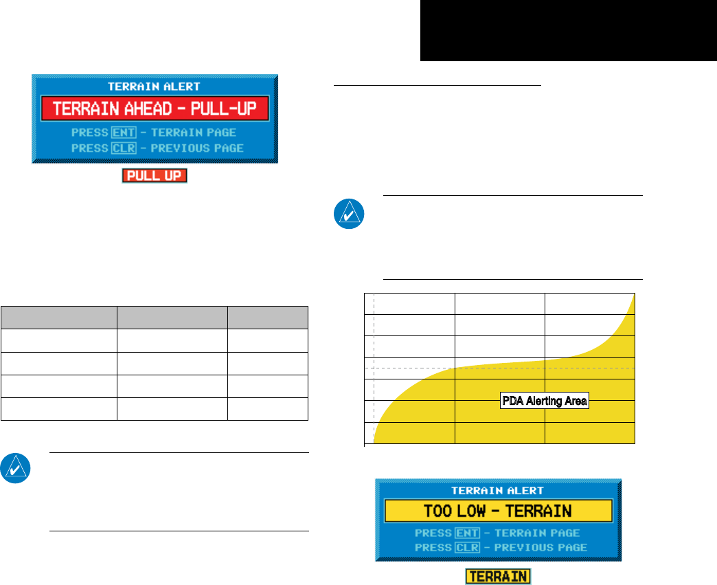
39
Part Three: Section 3
TAWS Alerts
WARNING— Estimated potential impact in approximately 15
seconds after alert and annunciation. FLTA warning alerts are
accompanied by the aural message “Terrain, Terrain; Pull
Up, Pull Up” or “Terrain Ahead, Pull Up; Terrain Ahead, Pull
Up”. Similarly, a “Obstacle, Obstacle; Pull Up, Pull Up” or
“Obstacle Ahead, Pull Up; Obstacle Ahead, Pull Up” alert is
also provided.
Phase of Flight Level Flight Descending
En Route 700 ft. 500 ft.
Terminal 350 ft. 300 ft.
Approach 150 ft. 100 ft.
Departure 100 ft. 100 ft.
Minimum TERRAIN Clearance Values for FLTA Alerts
NOTE: During the final approach phase of flight, FLTA
alerts are automatically inhibited when the aircraft
is below 200 feet AGL while within 0.5 NM of the
approach runway or is below 125 feet AGL while
within 1.0 NM of the runway.
Premature Descent Alerting (PDA)
TheTAWSsystemissuesaPrematureDescent
Alert(PDA)whenthesystemdetectsthattheaircraft
is significantly below the normal approach path to a
runway.PDAbeginswhentheaircraftiswithin15NM
of the destination airport.
PDA ends when the aircraft is either:
• 0.5 NM from the runway threshold
OR
• is below an altitude of 125 feet AGL while within
1.0 NM of the threshold.
(EIGHT!BOVE4ERRAIN&EET
$ISTANCE&ROM$ESTINATION!IRPORTNM
0$!!LERTING!REA0$!!LERTING!REA
2UNWAY
4HRESHOLD
CAUTION — The above annunciation and pop-up
terrain alert are displayed during a PDA alert. For
TAWS, the PDA alert is accompanied by the aural
message “Too Low, Terrain”.
190-00356-30 Rev F
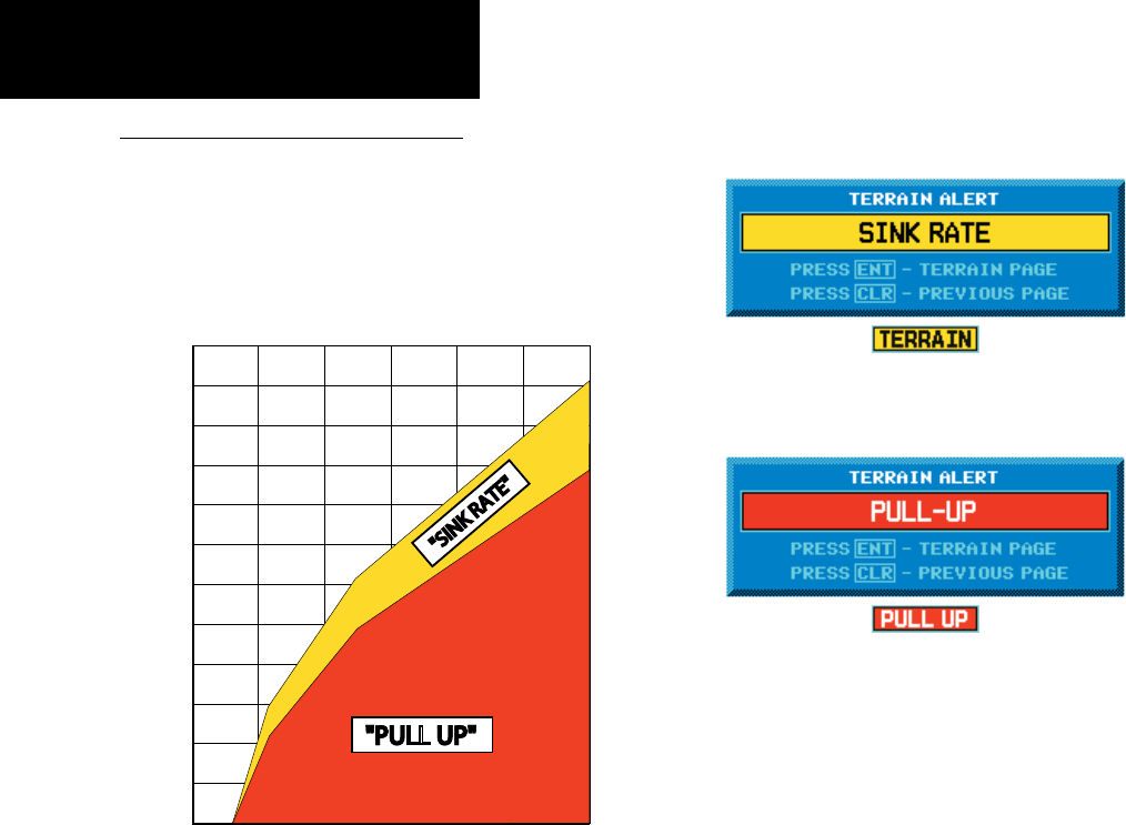
40
Part Three: Section 3
TAWS Alerts
Excessive Descent Rate Alert (EDR)
ThepurposeoftheExcessiveDescentRatealert
is to provide suitable notification when the aircraft is
determined to be closing (descending) upon terrain
atanexcessivespeed.Theparametersforthealertas
denedbyTSO-C151bareshownintheDescentRate
graph.
"PULL UP""PULL UP"
"SINK RATE"
$ESCENT2ATE
Height Above Terrain (Feet)
Excessive Descent Rate Graph
Excessive Descent Rate Severity Levels
CAUTION—The annunciation and pop-up terrain
alert are accompanied by the aural message “Sink
Rate”.
WARNING—The annunciation and pop-up terrain
alert are accompanied by the aural message “Pull
Up”.
190-00356-30 Rev F
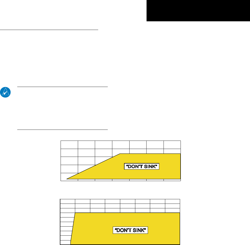
41
Part Three: Section 3
TAWS Alerts
Negative Climb Rate After Takeoff Alert (NCR)
ThepurposeoftheNegativeClimbRateAfter
Takeoffalert(alsoreferredtoas“AltitudeLossAfter
Takeoff”)istoprovidesuitablealertstothepilot
when the system determines that the aircraft is losing
altitude(closinguponterrain)aftertakeoff.The
auralmessage“Don’tSink”isgivenforNCRalerts,
accompanied by an annunciation and a pop-up terrain
alert on the display.
NCR alerting is only active when departing from an
airport and when the following conditions are met:
• The height above the terrain is less than 700 feet
• The distance from the departure airport is 2 NM or
less
• The heading change from the heading at the time of
departure is less than 110 degrees
TheNCRalertingparametersasdenedbyTSO-
C151bareshownintheNegativeClimbRateAlert
Criteriaguresbelow.TheNCRalertisissuedwhen
the altitude loss and height are within the range in the
rstgure,orwhenthesinkrate(negativevertical
speed) and height are within the range in the second
figure.
(EIGHT!BOVE4ERRAIN&EET
!LTITUDE,OSS&EET
h$/.43).+vh$/.43).+v
Negative Climb Rate (NCR) Alert Criteria
(EIGHT!BOVE4ERRAIN&EET
3INK2ATE&EET0ER-INUTE
h$/.43).+vh$/.43).+v
190-00356-30 Rev F
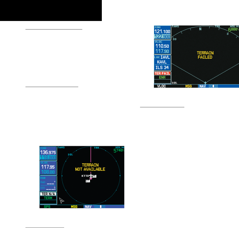
42
Part Three: Section 3
TAWS Alerts
“Five-Hundred” Aural Alert
The purpose of the aural alert message “Five-Hun-
dred” is to provide an advisory alert to the pilot that
the aircraft is five-hundred feet above terrain. When
theaircraftdescendswithin500feetofterrain,the
aural message “Five-hundred” is generated. There are no
display annunciations or pop-up alerts that accompany
the aural message.
TAWS Not Available Alert
GarminTAWSrequiresa3-DGPSnavigationsolu-
tion along with specific vertical accuracy minimums.
Should the navigation solution become degraded, or if
the aircraft is out of the database coverage area, the an-
nunciation“TERN/A”isgeneratedintheannunciation
window. When the GPS signal is re-established and the
aircraftiswithinthedatabasecoveragearea,the“TER
N/A”annunciationisremoved.
“TERRAIN NOT AVAILABLE” Display
TAWS Failure Alert
TAWS continually monitors several system-critical
items, such as database validity, hardware status, and
GPS status. If the terrain/obstacle database is not avail-
able, the aural message “TAWS System Failure” is issued
alongwiththe“TERFAIL”annunciation.
Figure 13-11: TAWS FAILED Display
TAWS Alert Summary
The aural alert voice gender is configurable to be
either male or female. Also, there are different alert
textphrasesavailableforseveralofthealerts,asshown
below. See your Garmin installer for further informa-
tion on configuring the alert system.
190-00356-30 Rev F
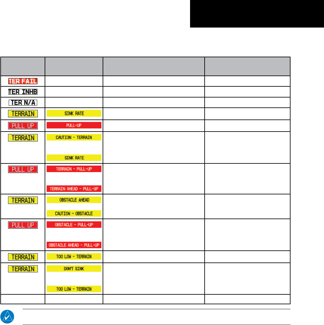
43
Part Three: Section 3
TAWS Alerts
TAWS Alerts Summary
TAWS
Annunciation Pop-Up Alert Aural Message Description
None “TAWS System Failure” TAWS has failed
None None TERRAIN has been inhibited by flight crew
None “Terrain Not Available” TAWS not available
“Sink Rate” Excessive Descent Rate Caution
“Pull Up” Excessive Descent Rate Warning
or
“Caution, Terrain; Caution, Terrain”
or
“Terrain Ahead; Terrain Ahead”
Forward Looking Terrain Avoidance
Caution for Terrain
or
“Terrain, Terrain; Pull Up, Pull Up”
or
“Terrain Ahead, Pull Up; Terrain Ahead, Pull Up”
Forward Looking Terrain Avoidance
Warning for Terrain
“Obstacle Ahead; Obstacle Ahead”
or
“Caution, Obstacle; Caution, Obstacle”
Forward Looking Terrain Avoidance
Caution for Obstacle
or
“Obstacle, Obstacle; Pull Up, Pull Up”
or
“Obstacle Ahead, Pull Up; Obstacle Ahead, Pull
Up”
Forward Looking Terrain Avoidance
Warning for Obstacle
“Too Low, Terrain” Premature Descent Alert Caution
or
“Don’t Sink”
or
“Too Low, Terrain”
Negative Climb Rate Caution
None None “Five-Hundred” 500 ft. AGL Altitude Callout
NOTE: TAWS Caution Alerts
are displayed as constant black text on a yellow background; TAWS Warning Alerts are displayed as
constant white text on a red background.
190-00356-30 Rev F

44
Part Three: Section 3
TAWS Alerts
Pilot Actions
If a TAWS warning and associated aural are received, the pilot should immediately respond to the aural and
pullupwithmaximumpowerandclimbrateunlesstheterrainorobstacleisclearlyidentiedvisuallyanddeter-
minedtonotbeasafetyofightfactor.ReferenceFAR91.223.
TAWS Caution indicates terrain or obstacle nearby. If possible visually locate the terrain or obstacle for avoid-
ance. A TAWS warning may follow a TAWS caution unless the aircraft’s path towards the terrain or obstacle is
changed.
NOTE: Display of terrain and obstacles on the display is supplemental data only. Maneuvering solely by reference to the ter-
rain and obstacle data is not recommended or authorized.
190-00356-30 Rev F

©2009GarminLtd.oritssubsidiaries
Garmin International, Inc.
1200East151stStreet,Olathe,Kansas66062,U.S.A.
Garmin AT, Inc.
2345TurnerRd.,S.E.,Salem,Oregon97302,U.S.A.
Garmin(Europe)Ltd.
LibertyHouse,BullsCopseRoad,HounsdownBusinessPark,
Southhampton,SO409RB,U.K.
Garmin Corporation
No.68,Jangshu2ndRoad,Shijr,TaipeiCounty,Taiwan
www.garmin.com
PartNumber:190-00356-30RevisionF
