Garmin 4010 Users Manual
5012 to the manual f927e7e8-c240-46b1-93f9-18c6d6fd99e8
2015-01-29
: Garmin Garmin-4010-Users-Manual-217294 garmin-4010-users-manual-217294 garmin pdf
Open the PDF directly: View PDF ![]() .
.
Page Count: 68
- Introduction
- Getting Started
- Using Charts
- Using the Navigation Chart
- Changing the Navigation Chart Settings
- Using Radar Overlay
- Using Tracks
- Using BlueChart g2 Vision
- Using Mariner’s Eye 3D
- Using Fish Eye 3D
- Using Fishing Charts
- Enabling High-Resolution Satellite Imagery
- Viewing Aerial Photos
- Viewing Current Station Information
- Detailed Road and POI Data
- Using Automatic Guidance
- Using Combinations
- Where To?
- Viewing Information
- Configuring the Chartplotter
- Using the Garmin Marine Network
- Using Radar
- Using Sonar
- Digital Selective Calling
- Appendix
- Index
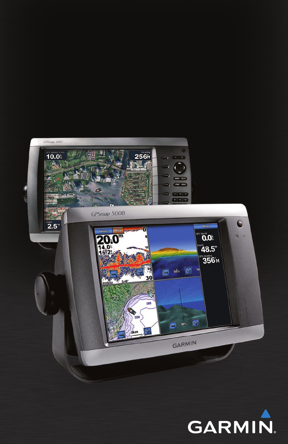
GPSMAP® 4000/5000 Series
owner’s manual
All rights reserved. Except as expressly provided herein, no part of this manual may be reproduced, copied, transmitted,
disseminated, downloaded or stored in any storage medium, for any purpose without the express prior written consent of
Garmin. Garmin hereby grants permission to download a single copy of this manual onto a hard drive or other electronic
storage medium to be viewed and to print one copy of this manual or of any revision hereto, provided that such electronic
or printed copy of this manual must contain the complete text of this copyright notice and provided further that any
unauthorized commercial distribution of this manual or any revision hereto is strictly prohibited.
Information in this document is subject to change without notice. Garmin reserves the right to change or improve its
products and to make changes in the content without obligation to notify any person or organization of such changes or
improvements. Visit the Garmin Web site (www.garmin.com) for current updates and supplemental information concerning
the use and operation of this and other Garmin products.
Garmin
®
, the Gamin logo, GPSMAP
®
, AutoLocate
®
, TracBack
®
, MapSource
®
, BlueChart
®
, and g2 Vision
®
are
trademarks of Garmin Ltd. or its subsidiaries, registered in the USA and other countries. UltraScroll
™
, GFS
™
, and GHP
™
are trademarks of Garmin Ltd. or its subsidiaries. These trademarks may not be used without the express permission
of Garmin. NMEA 2000
®
and the NMEA 2000 logo are registered trademarks of the National Maritime Electronics
Association. Windows
®
is a registered trademark of Microsoft Corporation in the United States and other countries.
© 2009 Garmin Ltd. or its subsidiaries
Garmin International, Inc.
1200 East 151st Street,
Olathe, Kansas 66062, USA
Tel. (913) 397.8200 or (800)
800.1020
Fax (913) 397.8282
Garmin (Europe) Ltd.
Liberty House
Hounsdown Business Park,
Southampton, Hampshire, SO40 9LR UK
Tel. +44 (0) 870.8501241 (outside the UK)
0808 2380000 (within the UK)
Fax +44 (0) 870.8501251
Garmin Corporation
No. 68, Jangshu 2nd Road,
Shijr, Taipei County, Taiwan
Tel. 886/2.2642.9199
Fax 886/2.2642.9099
April 2009 Part Number 190-01077-00 Rev. B Printed in Taiwan
See the Important Safety and Product Information guide in the product box for product warnings and other
important information.
GPSMAP
®
4000/5000 Series Owner’s Manual i
Introduction
Introduction
This manual includes information for the following products:
GPSMAP
®
4008
GPSMAP
®
4010
GPSMAP
®
4012
GPSMAP
®
5008
GPSMAP
®
5012
GPSMAP
®
5015
Tips and Shortcuts
Press or touch HOME from any screen to return to the Home screen.
Press or touch MENU from any main screen to access additional settings.
Press and release the Power key to adjust the display settings.
Press and hold the Power key to turn the unit on or off.
Manual Conventions
In this manual, when you are instructed to select an item, either press the soft key along the right
side of the screen (GPSMAP 4000 series units) or use your nger to touch that item on the screen
(GPSMAP 5000 series units) to select it. Small arrows (>) in the text indicate that you should select
each item in order. For example, if you see “select Charts > Navigation Chart,” you should press
the Charts soft key (GPSMAP 4000 series) or touch Charts (GPSMAP 5000 series), and then select
or touch Navigation Chart.
Quick Links
Turning the Unit On or Off: page 2.
Acquiring GPS Satellite Signals: page 3.
Inserting and Removing SD Cards: page 4.
Restoring Factory Settings: page 4.
Using the Navigation Chart: page 6.
Changing the Chart Settings: page 9.
Navigating to a Destination: page 21.
Creating a Waypoint: page 23.
Conguring System Settings: page 32.
Using Radar: page 39.
Using Sonar: page 45.
Digital Selective Calling: page 49.
Alarms and Messages: page 55.
•
•
•
•
•
•
•
•
•
•
•
•
•
•
•
•
•
•
•
•
•
•
•

ii GPSMAP
®
4000/5000 Series Owner’s Manual
Introduction
Table of Contents
Introduction ................................................i
Tips and Shortcuts ...........................................i
Manual Conventions ........................................i
Quick Links ......................................................i
Getting Started ..........................................1
Unit Overview ..................................................1
Turning the Unit On or Off ...............................2
Initializing Unit Settings ...................................2
Adjusting the Backlight ....................................3
Acquiring GPS Satellite Signals ......................3
Inserting and Removing SD Cards .................4
Restoring Factory Settings ..............................4
Viewing System Information ...........................4
Using Simulator Mode .....................................4
Understanding the Home Screen ....................5
Using Charts .............................................6
Using the Navigation Chart .............................6
Changing the Navigation Chart Settings .........9
Using Radar Overlay .....................................12
Using Tracks .................................................12
Using BlueChart g2 Vision ............................14
Using Mariner’s Eye 3D ................................14
Using Fish Eye 3D ........................................16
Using Fishing Charts .....................................16
Enabling High-Resolution Satellite Imagery ..17
Viewing Aerial Photos ...................................18
Viewing Current Station Information .............18
Detailed Road and POI Data ........................18
Using Automatic Guidance ............................18
Using Combinations ...............................19
Where To? ...............................................21
Navigating to a Destination ...........................21
Creating and Using Waypoints......................23
Creating and Using Routes ...........................25
Navigating with a Garmin Autopilot ...............26
Viewing Information ...............................27
Viewing Tide Station Information ..................27
Viewing Current Information .........................27
Viewing Celestial Information ........................28
Viewing User Data ........................................28
Viewing the DSC List ....................................30
Viewing Fuel Gauges ....................................31
Viewing Video ...............................................31
Conguring the Chartplotter .................32
Conguring System Settings .........................32
Changing the System Language ...................32
Conguring Navigation Preferences .............32
Conguring Units of Measure .......................33
Conguring Communications Settings ..........33
Setting Alarms ...............................................34
Setting the Total Fuel Onboard Alarm ...........35
Conguring My Boat .....................................35
Conguring Other Vessels ............................36
Using the Garmin Marine Network ........37
Viewing Connected Garmin Marine Network
Devices .......................................................38
Using Radar ............................................39
Using Cruising Mode .....................................40
Using Sentry Mode .......................................40
Radar Targeting ............................................41
Understanding the Radar Overlay Screen ....42
Obtaining Optimal Radar Display
Performance ...............................................42
Adjusting the VRM and EBL..........................43
Conguring Other Vessels on the Radar
Screen ........................................................43
Advanced Radar Conguration .....................44
Using Sonar ............................................45
Understanding the Full Screen .....................45
Understanding the Split Zoom Screen ..........45
Understanding the Split Frequency Screen ..46
Understanding the Temp Log ........................46
Setting Up Sonar ...........................................47
Advanced Sonar Settings .............................48
Digital Selective Calling (DSC) ..............49
Using the Chartplotter with a VHF Radio ......49
Adding a DSC Contact ..................................49
Viewing the DSC List ....................................50
Receiving Distress Calls ...............................50
Man-Overboard Distress Calls Initiated
from a VHF Radio .......................................50
Man-Overboard Distress Calls Initiated
from the Chartplotter ..................................50
Position Tracking ...........................................51
Placing an Individual Routine Call ................52
Calling an AIS Target ....................................52
Appendix .................................................53
Specications ................................................53
Calibrating the Touchscreen .........................54
Capturing Screenshots .................................54
Alarms and Messages ..................................55
Product Registration .....................................57
Contact Garmin .............................................57
Declaration of Conformity (DoC) ...................57
Software License Agreement ........................57
NMEA 0183 and NMEA 2000 ........................58
Index ........................................................59
GPSMAP
®
4000/5000 Series Owner’s Manual 1
Getting Started
Getting
Started
Getting Started
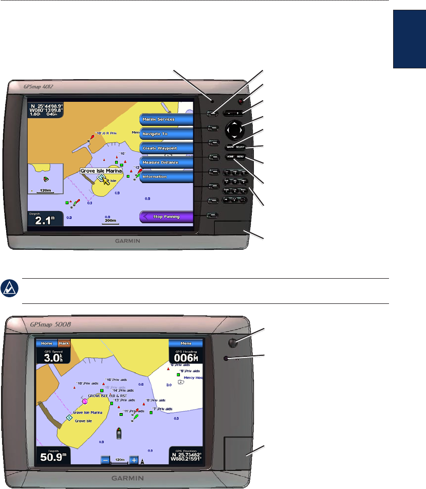
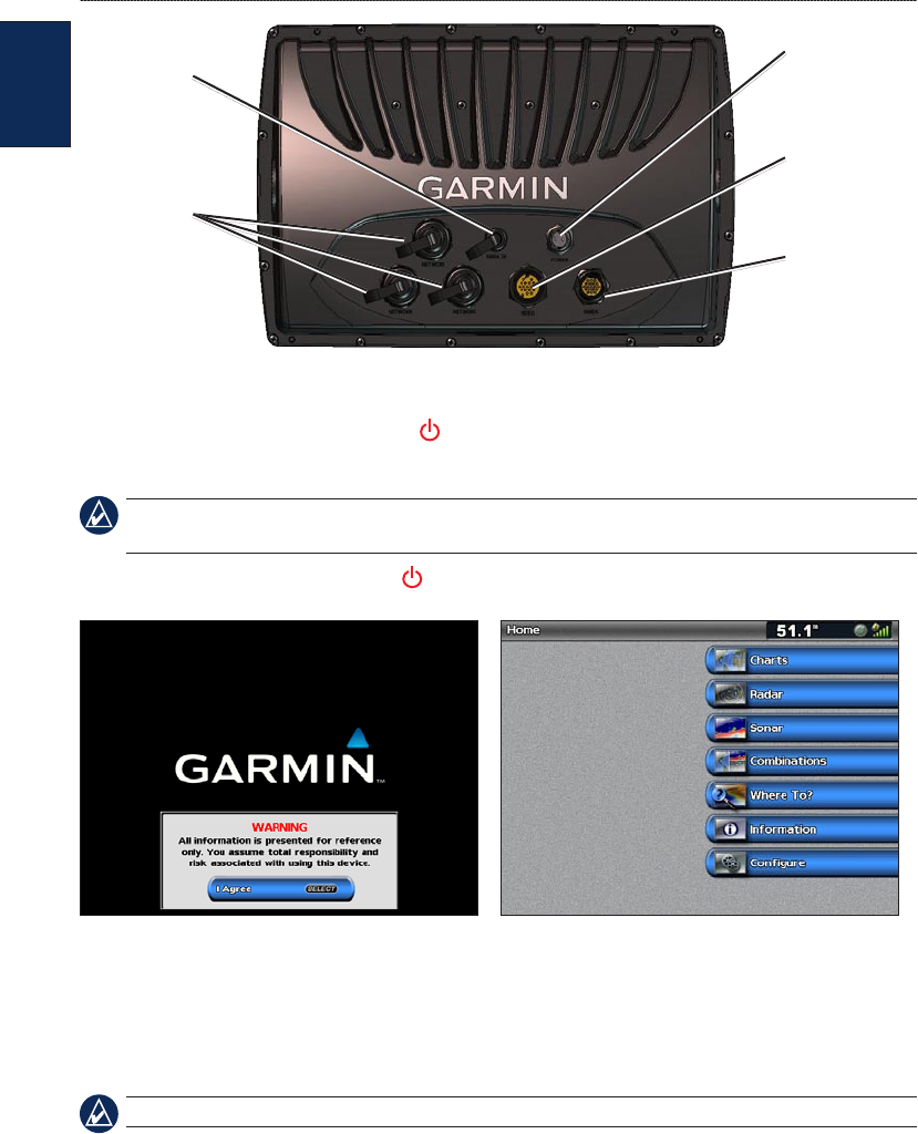
Unit Overview
SD card slot
Automatic backlight sensor
GPSMAP 4012
POWER
RANGE (+/-)
ROCKER
MARK
SELECT
HOME
MENU
Numeric keypad
(GPSMAP 4010 and 4012)
Soft keys
NOTE: Use the soft keys to select menu items on the GPSMAP 4000 Series. Touch menu items on the
GPSMAP 5000 Series screen to select them.
SD card slot
POWER
Automatic backlight
sensor
GPSMAP 5008
2 GPSMAP
®
4000/5000 Series Owner’s Manual
Getting Started
Getting
Started
Power
connector
Marine video
connector
NMEA 2000
connector
NMEA 0183
connector
Garmin Marine
Network
connectors
Turning the Unit On or Off
To turn the unit on, press and release the Power key. When the Warning screen appears, select
I Agree to open the Home screen.
NOTE: The rst time you turn on your unit, you must go through a setup sequence. See “Initializing
Unit Settings.”
To turn the unit off, press and hold the Power key.
Warning Screen Home Screen
Initializing Unit Settings
The rst time you turn your unit on, you must congure a series of initial settings. These settings
must also be congured when restoring factory settings.
NOTE: You can change these settings later using the Congure screen.
Language—select the language to display on your screen.
Welcome—select OK.
Position Format—specify the coordinate system to use for location readings.
Time Format—specify whether you want the time shown in a 12-hour, 24-hour, or UTC
(Universal Time Code) format.
Time Zone—select your time zone.
Units—specify units for on screen measurements as Statute, Metric, or Nautical.
GPSMAP
®
4000/5000 Series Owner’s Manual 3
Getting Started
Getting
Started
Minimum Safe Depth—select the minimum safe depth for your boat. Refer to your boat
specications for more information.
Minimum Overhead Clearance—select the minimum overhead clearance for your boat. Refer to
your boat specications for more information.
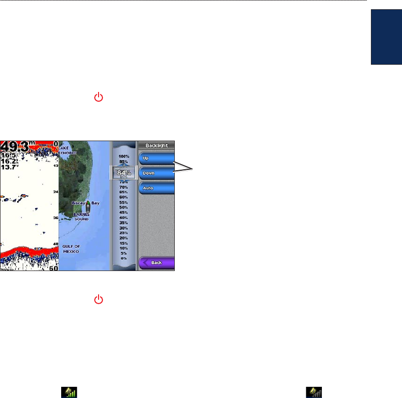
Adjusting the Backlight
1. Press and release the Power key.
2. Select Backlight.
To allow the unit to automatically adjust the backlight based on ambient light, select Auto.
To manually adjust the backlight,
either select Up or Down, use the
ROCKER (GPSMAP 4000 series),
or touch and drag the brightness
bar (GPSMAP 5000 series).
To adjust the color mode:
1. Press and release the Power key.
2. Select Color Mode.
3. Select Day Colors, Night Colors, or Auto.
Acquiring GPS Satellite Signals
When you turn the unit on, the GPS receiver must collect satellite data and establish its current
location. When the unit acquires satellite signals, the signal strength bars at the top of the Home
screen are green . When the unit loses satellite signals, the green bars disappear and the
position icon shows a ashing question mark.
For more information about GPS, visit the Garmin
®
Web site at www.garmin.com/aboutGPS.
4 GPSMAP
®
4000/5000 Series Owner’s Manual
Getting Started
Getting
Started
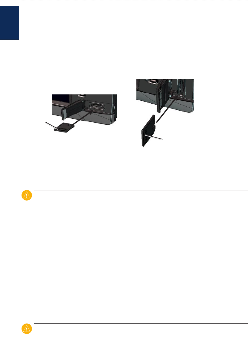
Inserting and Removing SD Cards
Your unit supports Secure Digital (SD) cards. Insert optional BlueChart
®
g2 Vision
®
SD cards to
view high-resolution satellite imagery, and aerial reference photos of ports, harbors, marinas, and
other points of interest. Insert blank SD cards to transfer data such as waypoints, routes, and tracks
to another compatible Garmin unit or a computer. The SD card slot is located on the lower-right
corner of the unit.
To insert the SD card, open the access door and press the SD card in until it clicks. Press the card in
again and release it to eject it from the chartplotter.
Card label
GPSMAP 4010 and 4012
Card label
GPSMAP 4008 and 5000 series
Restoring Factory Settings
You can restore your unit to the original factory settings.
CAUTION: This procedure deletes any information you have entered.
To restore factory settings:
1. From the Home screen, select Congure > System > System Information.
2. Select Factory Settings.
3. Select Reset to restore all factory settings or select Back to cancel.
Viewing System Information
You can view the software version, basemap version, and unit ID number for your chartplotter.
You may need this information to update the system software or to purchase additional map data
information.
From the Home screen, select Congure > System > System Information.
Using Simulator Mode
Simulator Mode turns the GPS receiver off for use indoors or for practice. The unit does not track
satellites in simulator mode.
CAUTION: Do not try to navigate using Simulator Mode because the GPS receiver is turned off. Any
satellite signal strength bars shown are only simulations and do not represent the strength of actual
satellite signals.
To turn Simulator Mode on:
1. From the Home screen, select Congure > System > Simulator > On.
2. Select Setup to set speed, track control, position, simulator time, and simulator date.
GPSMAP
®
4000/5000 Series Owner’s Manual 5
Getting Started
Getting
Started
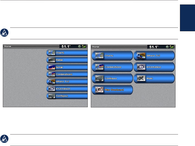
Understanding the Home Screen
Use the Home screen to access all other screens. Select Home from any screen to return to the Home
screen.
NOTE: Options on this screen vary based on the unit type. When you add additional hardware to your
Garmin Marine Network, additional options appear.
GPSMAP 4000 Series Home Screen GPSMAP 5000 Series Home Screen
Charts—access Navigation Chart, Perspective 3D, Mariner’s Eye 3D, Fish Eye 3D, Fishing
Charts and Radar Overlay (page 6).
NOTE: Mariner’s Eye 3D, Fish Eye 3D, and Fishing Charts are available only if you use a
BlueChart g2 Vision SD card.
Radar—set up and view radar (page 39).
Sonar—set up and access sonar information (page 45).
Combinations—set up the screen to view a chart, sonar, radar, and video in a two or three
(GPSMAP 4000 Series) eld, or four (GPSMAP 5000 Series) eld split screen (page 19).
Where To?—access navigation features (page 21).
Information—view information including tides, currents, celestial data, user data, information
about other boats, gauges, and video (page 27).
Congure—access unit and system settings (page 32).
Mark—mark, edit, or delete your current location as a waypoint or MOB
(GPSMAP 5000 Series).
Man Overboard—navigate to a Man Overboard location (GPSMAP 5000 series).
•
•
•
•
•
•
•
•
•
6 GPSMAP
®
4000/5000 Series Owner’s Manual
Using Charts
Using
Charts
Using Charts
Your unit has a basic worldwide imagery map. By purchasing an optional Blue Chart g2 Vision
preprogrammed SD card, you can view detailed information for your region, including:
Navigation Chart—displays navigation data, including buoys, lights, cables, depth soundings,
marinas, and tide stations in an overhead view.
Mariner’s Eye 3D—displays a view from above and behind your boat for a visual navigation
aid.
Fish Eye 3D—an underwater view that visually represents the sea oor according to the
information on the chart.
Fishing Chart—removes navigational data from the chart and enhances bottom contours for
depth recognition.
The unit automatically shows relevant navigational data when you select a navigation option.
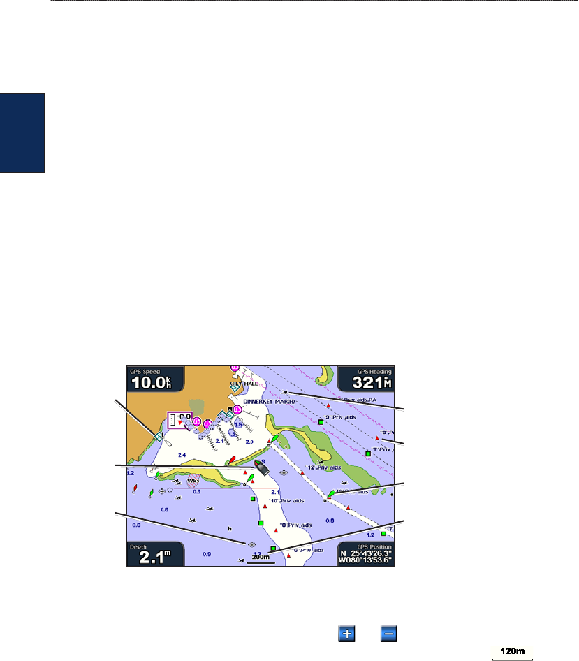
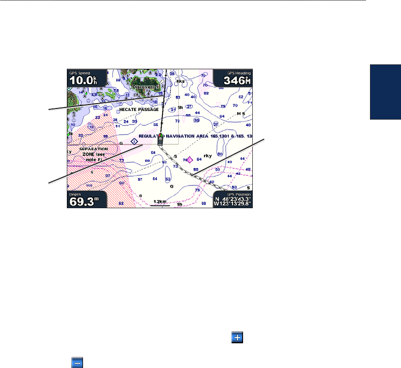
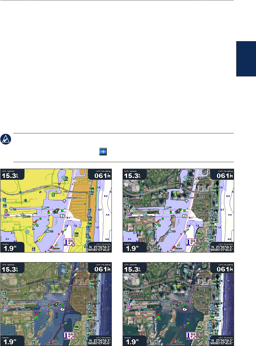
Using the Navigation Chart
Use the Navigation chart to plan your course, to view map information, and as a navigational aid.
To access the Navigation chart, from the Home screen, select Charts > Navigation Chart.
Navigation Chart with BlueChart g2 Vision Data
Buoy
Beacon
Your boat
Exposed
wreck
Marine
services
Zoom scale
Submerged
wreck
Zooming In and Out on the Map
The RANGE (+/-) keys (GPSMAP 4000 series) or the and keys (GPSMAP 5000 series)
control the zoom level, indicated by the scale at the bottom of the Navigation chart ( ). The
bar under the number represents that distance on the map.
Navigation Chart Menu
To access additional settings or options for the Navigation chart, select Menu.
Waypoints & Tracks—view and add waypoints and tracks, and congure how they are displayed.
Other Vessels—view information about other vessels. To view information about other vessels,
your unit must be connected to an external AIS (Automatic Identication System) or DSC (Digital
Selective Calling) device.
Stop Navigation—stop navigating to your destination (only available while navigating).
Chart Setup—customize the Navigation chart settings (page 9).
•
•
•
•
GPSMAP
®
4000/5000 Series Owner’s Manual 7
Using Charts
Using
Charts
Understanding Chart Data
BlueChart g2 and BlueChart g2 Vision charts use graphic symbols to denote map features, which
follow the standards for US and international charts.
Other features common to most charts include depth contour lines (with deep water represented in
white), intertidal zones, spot soundings (as depicted on the original paper chart), navigational aids
and symbols, and obstructions and cable areas.
Navigating to a Point on the Chart
1. From the Home screen, select Charts.
2. Select Navigation Chart, Fishing Chart, or Radar Overlay.
3. Select the point on the chart to which you want to go.
4. Select Navigate To.
5. Select Go To (or Guide To when using a preprogrammed BlueChart g2 Vision card for Auto
Guidance).
6. Follow the colored line on the screen to the destination.
To create a route to a point on the chart, see page 25.
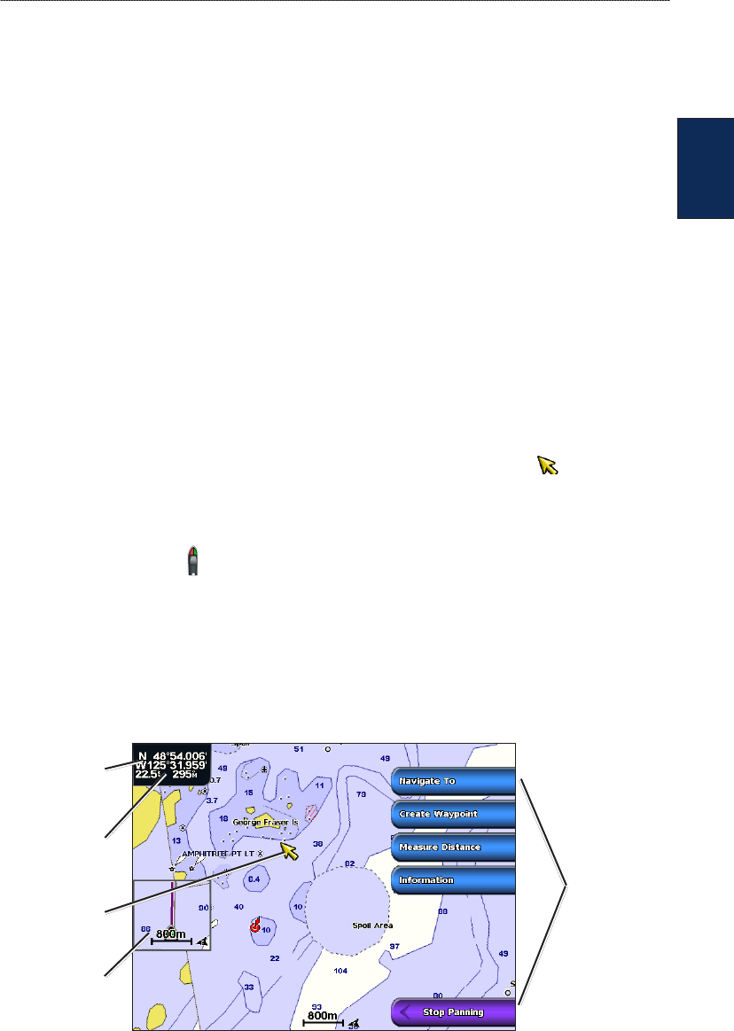
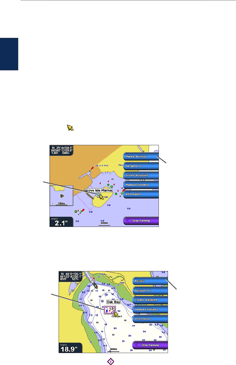
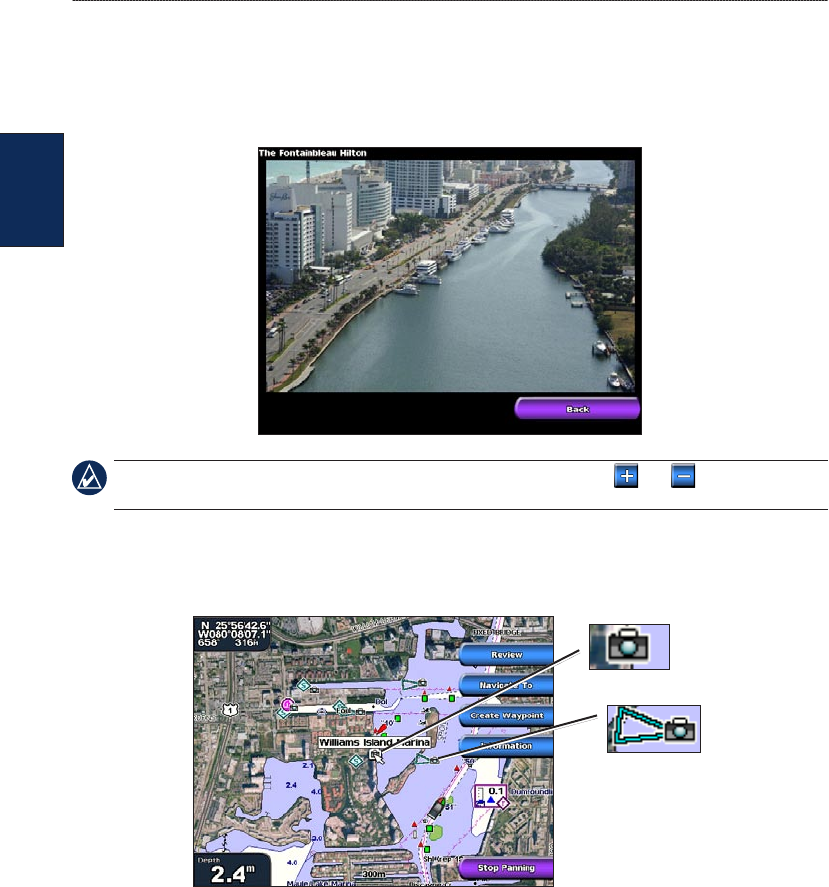
Panning the Navigation Chart
Use the ROCKER on your GPSMAP 4000 series unit to move the map pointer ( ) away from
your current location and to scroll to other areas on the Navigation chart. As you pan past the edge
of the current map display, the screen scrolls forward to provide continuous map coverage. Touch
and drag the Navigation screen on your GPSMAP 5000 series unit to pan away from your current
location. The position icon ( ) stays at your present location. If the position icon leaves the map
when you pan, a small window (inset map) appears on the left of the screen so that you can keep
track of your current position.
As you move the map pointer, its coordinates, distance, and bearing from your current location
appear in the upper-left corner of the map.
To pan the map, press up, down, right, or left on the ROCKER (GPSMAP 4000 series), or touch
and drag the Navigation screen (GPSMAP 5000 series).
Map
pointer
Inset
map
Pan
options
Pointer distance
and bearing
from current
location
Pointer
coordinates
To stop panning, select Stop Panning.
8 GPSMAP
®
4000/5000 Series Owner’s Manual
Using Charts
Using
Charts
As you pan the map, a list of options appears along the right side. The options change as you move
the map pointer over various objects and charts.
Review—(Review will not appear if the pointer is not near an object—if the pointer is near only
one object, the name of the object appears.) This allows you to view details of objects in the
vicinity of the pointer. When you select Review, you are presented with a list of all the objects
near the pointer.
Navigate To—begin navigation to the pointer location.
Measure Distance—select Set Reference to mark a starting point. Move the pointer (GPSMAP
4000 series) or touch the screen (GPSMAP 5000 series) to select a starting point from which to
measure distances. The distance is displayed in the upper left corner of the screen.
Create Waypoint—mark a waypoint at the pointer location.
Information—view tide, current, celestial, or local services information near the pointer
location.
Accessing Additional Object Information
Use the map pointer ( ) (GPSMAP 4000 series) or touch an item on the screen
(GPSMAP 5000 series) to view information about on-screen map items, waypoints, and charts.
Selected
item
Additional item
information
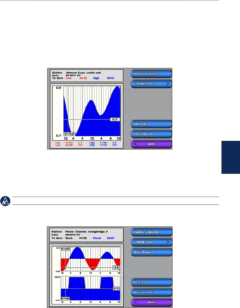
Viewing Tide-Station Information
Tide-station information appears on the chart with a detailed icon showing the relevant tide level.
You can view an in-depth graph for a tide station to help predict the tide level at different times or on
different days.
Relevant tide
level
Detailed
tide station
information
Highlight or touch a tide-station icon ( ), and select Review to view a detailed tide graph.
•
•
•
•
•
GPSMAP
®
4000/5000 Series Owner’s Manual 9
Using Charts
Using
Charts
Changing the Navigation Chart Settings
To change the Navigation chart settings from the Home screen, select Charts > Navigation Chart >
Menu > Chart Setup.
Photos—sets the high-resolution satellite images to off, land only, or blend. High-resolution satellite
imagery is only available while using a BlueChart g2 Vision SD card.
Tides/Currents—turns the display of tides and currents on or off (page 27).
Service Points—turns the display of marine service points on or off.
Roses—displays a compass rose around your boat, indicating compass direction. True wind or
apparent wind direction can be displayed if the unit is connected to a compatible marine wind sensor.
Compass rose
Wind direction
indicator
Wind Compass Rose
Data Bars—show or hide cruising, navigation, shing, fuel, or sailing numbers.
Cruising—turn the GPS Speed, GPS Heading, Depth, and GPS Position data bar on or off.
Select Data Bar Setup to congure the position of the data on the screen.
Navigation—turn the Distance to Destination, Arrival, Off Course, and Bearing data bar on or
off. If you select Auto, the chartplotter will turn the Navigation data bar on whenever you are
navigating to a destination. Select Data Bar Setup to congure the Route Leg, Next Turn, and
Destination options.
Fishing—turn the Depth, Water Temperature, and Water Speed data bar on or off.
Fuel—turn the Fuel Rate, Remaining Fuel, Range, and Fuel Economy data bar on or off.
Sailing—turn the Water Speed, Wind Speed, Wind Angle, and Wind Velocity Made Good (VMG)
data bar on or off. Select Wind to toggle between True and Apparent wind speed and wind angle.
Data bars
•
•
•
•
•

10 GPSMAP
®
4000/5000 Series Owner’s Manual
Using Charts
Using
Charts
Understanding How Wind VMG and Waypoint VMG Are Displayed in the
Data Bars
The chartplotter automatically switches between displaying Wind Velocity Made Good (VMG) and
Waypoint VMG in the data bars.
Waypoint VMG is displayed under these conditions:
The Route Leg data bar displays Waypoint VMG when you are navigating a route or an
automatic guidance line.
The Sailing data bar displays Waypoint VMG when you are navigating a route or an automatic
guidance line, and you turn the Route Leg data bar off. For more information on conguring the
data bars, see page 9.
Wind VMG is displayed under these conditions:
The Sailing data bar displays Wind VMG when you are not navigating a route or an automatic
guidance line.
The Sailing data bar displays Wind VMG when the Route Leg data bar is on.
Changing the Chart Appearance
From the Home screen, select Charts > Navigation Chart > Menu > Chart Setup > Chart
Appearance.
Orientation—changes the perspective of the map display.
North Up—sets the top of the map display to a north heading.
Head Up—sets the map display to the current track heading.
Course Up—sets the map so the direction of navigation is always up. The heading line appears
vertically on the screen if shown.
Detail—adjusts the amount of detail shown on the map at different zoom levels.
Heading Line—draws an extension from the bow of the boat in the direction of travel.
Off—turns the heading line off.
Distance—sets the distance to the end of the heading line.
Time—sets the amount of time until you reach the end of the heading line.
World Map—displays either a basic world map or displays satellite imagery (when Full World
Map is selected).
Inset Map—turns the inset map on or off when panning away. Select Auto to turn the inset map on
only when the boat symbol is no longer visible.
Spot Depths—turns spot soundings on or off and sets a dangerous depth.
Safety Shading (with supported BlueChart g2 Vision cards)—Areas with depths shallower than
the specied value are shaded in blue, while areas with depths greater than the specied value are
shaded in white. The contour is always drawn at or deeper than the selected depth.
Symbols—changes symbol preferences.
Navaid Size—adjusts the size of the navaid symbols shown on the map.
Navaid Type—selects the navaid symbol set (NOAA or IALA).
Land POIs—turns the display of land POIs (points of interest) on or off.
•
•
•
•
•
•
•
•
•
•
•
•
•
GPSMAP
®
4000/5000 Series Owner’s Manual 11
Using Charts
Using
Charts
Light Sectors—turns the sector in which a navigational light is visible on or off. Selecting On
lters out light sectors depending on the zoom level.
Chart Borders—turns chart borders on when using a BlueChart g2 Vision SD card and you want
to see what area the maps cover.
Heading line
Track
Chart border
Photo Points—turns camera icons (page 18) on or off when using a BlueChart g2 Vision SD card.
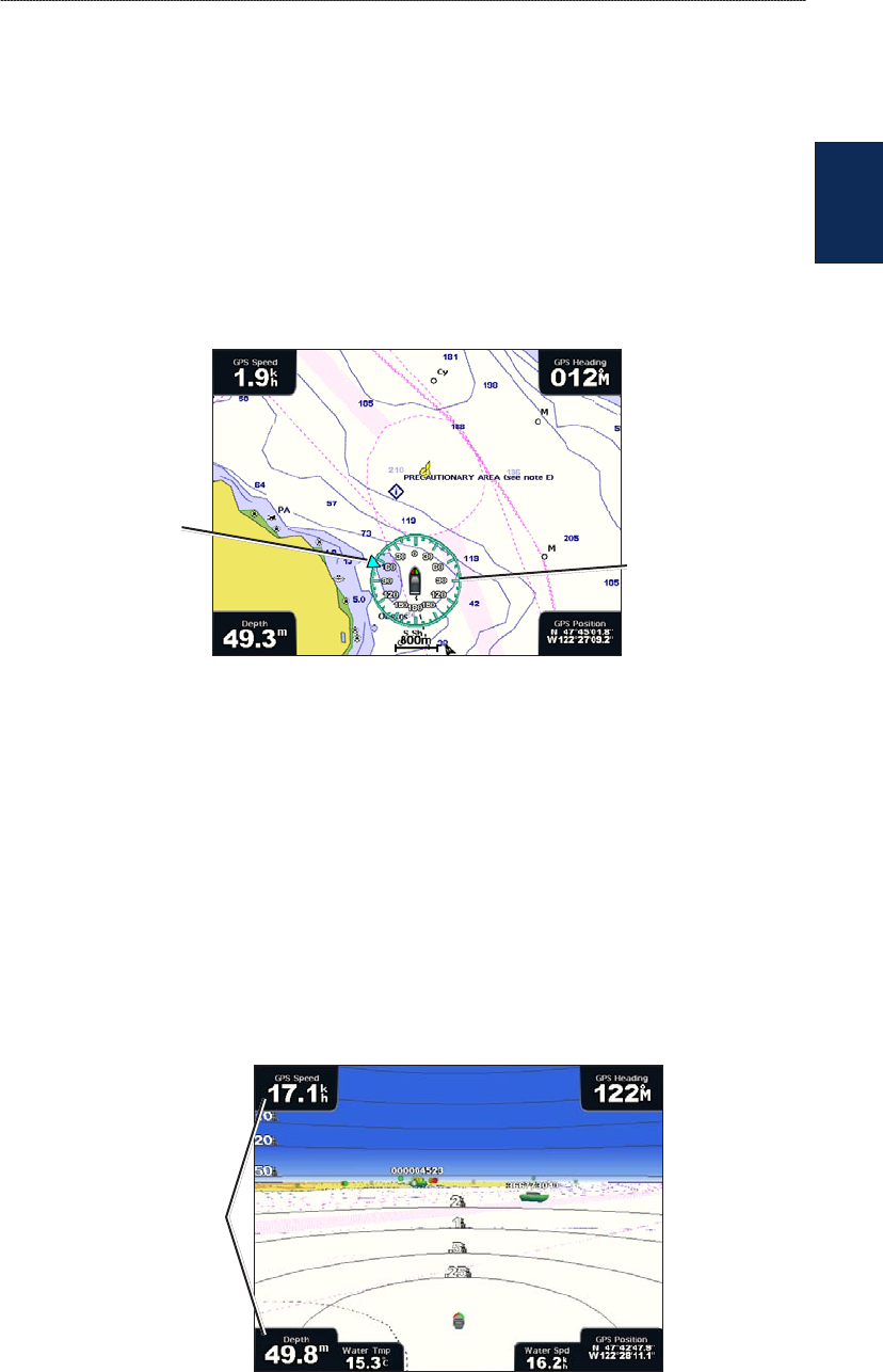
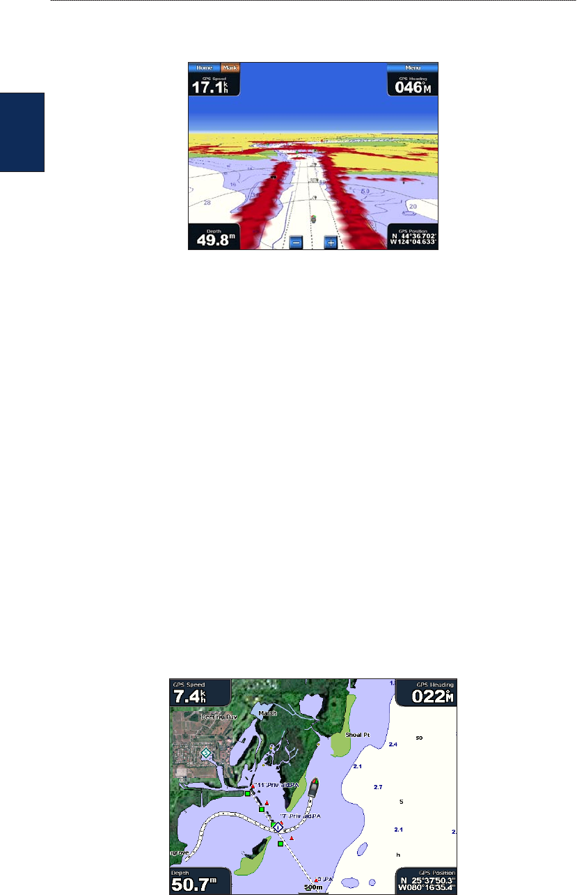
Using Perspective 3D
Perspective 3D provides a view from above and behind the boat (according to your course), and
provides a visual navigation aid. This view is helpful when navigating tricky shoals, reefs, bridges,
or channels, and is benecial when trying to identify entry routes and exit routes in unfamiliar
harbors or anchorages.
To access the Perspective 3D screen, from the Home screen, select Charts > Perspective 3D.
Press the RANGE (+) key (GPSMAP 4000 series) or touch the key (GPSMAP 5000 series) to
move the view closer to your boat and lower to the water. Press the RANGE (-) key (GPSMAP 4000
series) or touch the key (GPSMAP 5000 series) to move the view away from the boat.
To view details about navaids such as beacons, lights, and obstructions:
1. Use the ROCKER (GPSMAP 4000 series) or the touchscreen (GPSMAP 5000 series) to point to
the navaid. When the cursor is over the navaid, a button is displayed, such as Beacon or Light.
2. Select the button for the navaid to view details.
Perspective 3D Settings
To access additional settings or options from the Perspective 3D screen, select Menu.
Waypoints & Tracks—view and add waypoints and tracks, and congure how they are displayed.
Tracks—turn tracks on or off (page 12).
Waypoints—view, sort, or lter existing waypoints, or create new ones.
New Waypoint—edit, delete, or create a new waypoint.
Active Tracks—manage tracks (page 12).
Saved Tracks—view a list of tracks that have been saved.
Other Vessels—view information about other vessels. To view information about other vessels,
your unit must be connected to an external AIS (Automatic Identication System) or DSC (Digital
Selective Calling) device.
•
•
•
•
•
•
•
12 GPSMAP
®
4000/5000 Series Owner’s Manual
Using Charts
Using
Charts
Surface Radar—display radar reections from the surface of the water when the unit is connected
to a marine radar (page 39).
Perspective 3D With Surface Radar Information
Data Bars—show or hide cruising, navigation, shing, fuel, or sailing numbers (page 9).
Chart Appearance—customize the Perspective 3D chart.
Range Rings—toggles the range rings on or off to provide distance measurement.
Safe Depth—adjusts the safe depth for your boat. If the unit is connected to an optional sonar
module and the shallow water alarm is activated (page 56), an alarm will sound when your boat
enters water shallower than this setting.
Lane Width—adjusts the width of the course line drawn when navigating. This setting also
affects routes (Route To), but does not affect automatic guidance (Guide To).
Using Radar Overlay
When you connect your chartplotter to an optional Garmin marine radar, you can use Radar Overlay
to overlay radar information on the Navigation chart (page 42).
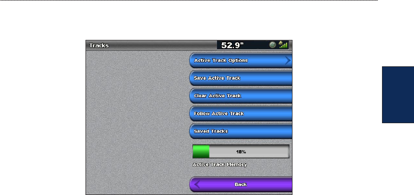
Using Tracks
A track is a recording of your path. The track currently being recorded is the active track. An active
track can be saved.
To turn the track log on:
From the Navigation or Perspective 3D chart, select Menu > Waypoints & Tracks > Tracks >
On. A trailing line on the chart indicates your track.
•
•
•
GPSMAP
®
4000/5000 Series Owner’s Manual 13
Using Charts
Using
Charts
To save the active track:
1. From the Home screen, select Information > User Data > Tracks > Save Active Track.
2. Select either the time the current track began (or Midnight, if shown) or Entire Log.
3. To name the track, change the color of the track, or save it as a route, select Edit Track.
To clear the active track:
From the Home screen, select Information > User Data > Tracks > Clear Active Track. The
track memory is cleared; the current track continues to be recorded.
To retrace the active track:
1. From the Home screen, select Information > User Data > Tracks > Follow Active Track.
2. Select either the time the current track began or Entire Log.
3. Follow the colored line on the screen.
To edit or delete a saved track:
1. From the Home screen, select Information > User Data > Tracks > Saved Tracks.
2. Select the track you want to edit or delete.
3. Select Edit Track to change the name or color of the track, or select Delete to delete it.
To set active Track Options:
From the Home screen, select Information > User Data > Tracks > Active Track Options.
Record Mode—select Off, Fill, or Wrap.
Off—does not record a track log.
Fill—records a track log until the track memory is full.
Wrap—continuously records the track log, replacing the oldest track data with new data.
Interval—denes the frequency at which the track plot is recorded. Recording more-frequent plots
is more accurate but lls the track log faster.
Interval—sets whether the interval is determined by distance, time, or resolution. (Select
Change to set the value.)
Distance—records the track based on a distance between points.
Time—records the track based on a time interval.
•
•
•
•
•
•
14 GPSMAP
®
4000/5000 Series Owner’s Manual
Using Charts
Using
Charts
Resolution—records the track plot based on a variance from your course. This setting is
recommended for the most-efcient use of memory. The distance value (Change) is the
maximum error allowed from the true course before recording a track point.
Change—sets the value of the interval.
Track Color—sets the color of the track plot.
Using BlueChart g2 Vision
Optional BlueChart g2 Vision preprogrammed SD cards allow you to get the most out of your unit.
In addition to detailed marine charting, BlueChart g2 Vision has the following features:
Mariner’s Eye 3D—provides a view from above and behind the boat for a three-dimensional
navigation aid. The BlueChart g2 Vision Mariner’s Eye 3D is more detailed than the preloaded
data.
Fish Eye 3D— provides an underwater 3D view that visually represents the sea oor according
to the information on the chart.
Fishing Charts—provides a view of the chart with enhanced bottom contours and without
navigational data. This chart works well for offshore deep-sea shing.
High Resolution Satellite Imagery—provides high-resolution satellite images for a realistic
view of the land and water on the Navigation chart.
Aerial Photos—provides a view of marinas and other navigationally signicant aerial photos to
help you visualize your surroundings.
Detailed Roads and POI data—provides a view of roads, restaurants, and other points of
interest (POIs) along the shore.
Current Data—provides a view of current station information.
Auto Guidance—uses the chart data and specied boat safe depth to determine the best course to
your destination.
NOTE: You cannot transfer BlueChart g2 Vision data from the SD card to your computer for backup or
viewing purposes. You can only use the SD card on BlueChart g2 Vision-compatible Garmin GPS units.
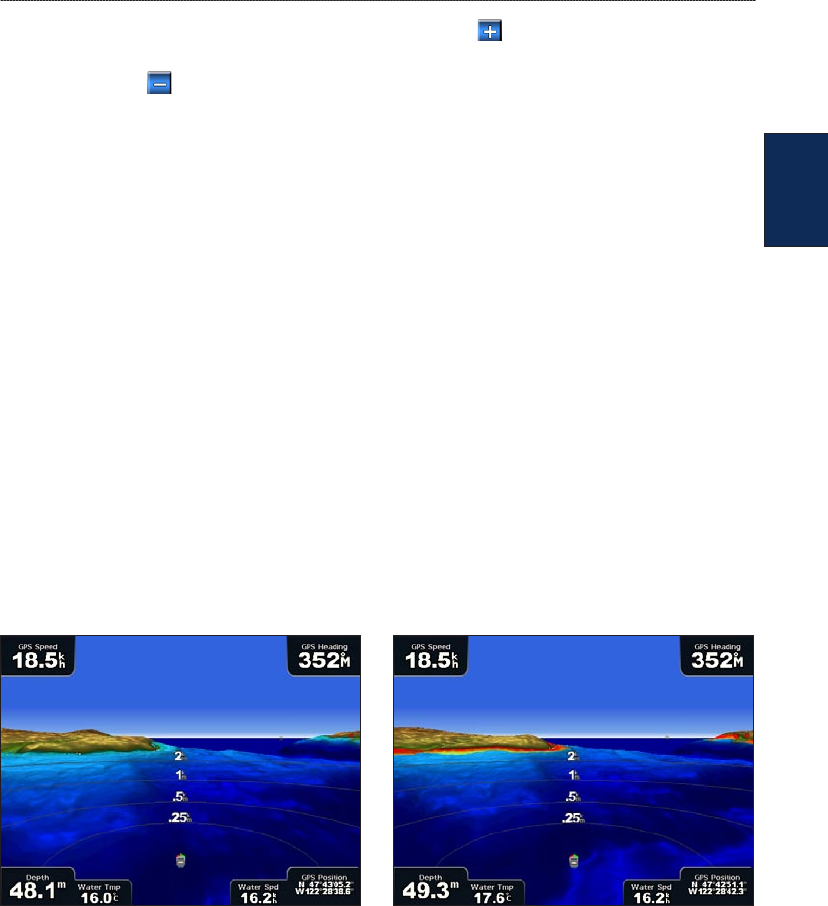
Using Mariner’s Eye 3D
A BlueChart g2 Vision SD card offers Mariner’s Eye 3D, which provides a detailed three-
dimensional view from above and behind the boat (according to your course), and provides a visual
navigation aid. This view is helpful when navigating tricky shoals, reefs, bridges, or channels, and is
benecial when trying to identify entry and exit routes in unfamiliar harbors or anchorages.
Mariner’s Eye 3D Navigation Chart
•
•
•
•
•
•
•
•
•
•
GPSMAP
®
4000/5000 Series Owner’s Manual 15
Using Charts
Using
Charts
Press the RANGE (+) key (GPSMAP 4000 series) or touch the key (GPSMAP 5000 series) to
move the view closer to your boat and lower to the water. Press the RANGE (-) key (GPSMAP 4000
series) or touch the key (GPSMAP 5000 series) to move the view away from the boat.
To view details about navaids such as beacons, lights, and obstructions:
1. Use the ROCKER (GPSMAP 4000 series) or the touchscreen (GPSMAP 5000 series) to point to
the navaid. When the cursor is over the navaid, a button is displayed, such as Beacon or Light.
2. Select the button for the navaid to view details.
Mariner’s Eye 3D Settings
To access additional settings or options from the Mariner’s Eye 3D screen, select Menu.
For settings and options related to Waypoints & Tracks, Other Vessels, Surface Radar, and Data
Bars, see “Perspective 3D Settings” on page 11.
To customize the appearance of the Mariner’s Eye 3D screen, select Menu > Chart Appearance.
Style—Selects how chart data is displayed over 3D terrain.
Classic—uses color schemes to indicate 3D terrain.
Charts—provides chart information in a 3D view.
Photos—provides satellite photo imagery in addition to chart information.
Hazard Colors—Turns hazard colors on or off. The Off setting shows the land as seen from the
water. The On setting indicates shallow water and land with a color scale. Blue indicates deep water,
yellow is shallow water, and red is very shallow water.
Mariner’s Eye 3D, Hazard Colors Off Mariner’s Eye 3D, Hazard Colors On
For settings and options related to Range Rings, Safe Depth, and Lane Width, see page 12.
•
•
•
16 GPSMAP
®
4000/5000 Series Owner’s Manual
Using Charts
Using
Charts
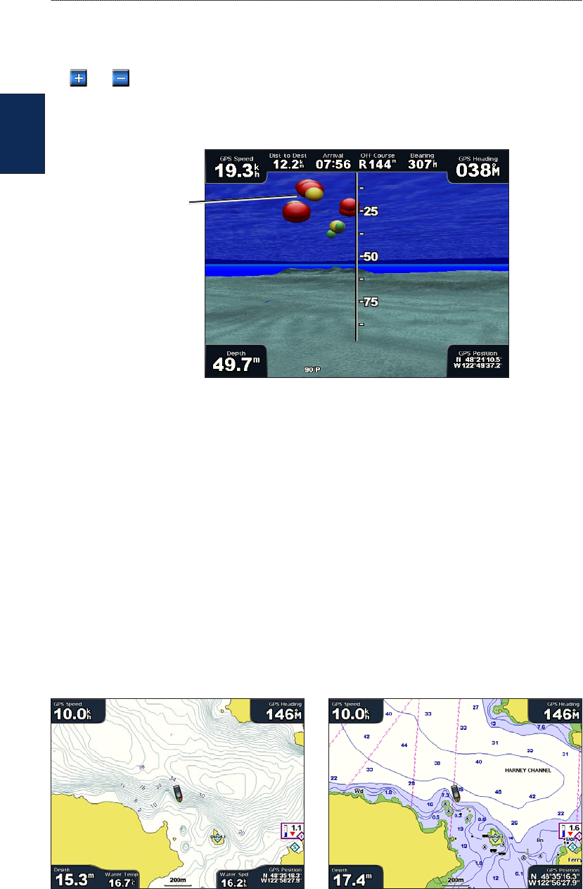
Using Fish Eye 3D
Using the depth contour lines of the BlueChart g2 Vision cartography, Fish Eye 3D provides an
underwater view of the sea oor or lake bottom. Use the RANGE keys (GPSMAP 4000 series) or
the and keys (GPSMAP 5000 series) to adjust the view.
Suspended targets (such as sh) are indicated by red, green, and yellow spheres. Red indicates the
largest targets and green indicates the smallest.
Fish Eye 3D
Suspended
targets
Fish Eye 3D Settings
To access additional settings or options for the Fish Eye 3D screen, select Menu.
View—selects a sh eye view of Fore, Aft, Port, or Starboard.
Sonar Cone—turns a cone that shows the area covered by your transducer on or off.
Sonar Data—visually shows the sonar readings received by your transducer for the best
combination of sonar and mapping.
Tracks—turns the track log on or off.
Data Bars—show or hide cruising, navigation, shing, fuel, or sailing numbers (page 9).
Using Fishing Charts
Use the Fishing chart for a detailed, unobstructed view of the bottom contours and depth soundings
on the chart.
Fishing Chart Navigation Chart
GPSMAP
®
4000/5000 Series Owner’s Manual 17
Using Charts
Using
Charts
The Fishing chart uses detailed bathymetric data on a preprogrammed BlueChart g2 Vision SD card,
and is best for offshore deep-sea shing.
Enabling High-Resolution Satellite Imagery
You can overlay high-resolution satellite images on the land, the sea, or both portions of the
Navigation chart when using a preprogrammed BlueChart g2 Vision SD card.
To enable satellite imagery:
1. While viewing the Navigation chart, select Menu.
2. Select Chart Setup > Photos.
3. Select one of the following:
Off—standard chart information is shown on the map.
Land Only—standard chart information is shown on water with photos overlaying the land.
Photo Map—photos overlay both the water and the land at a specied opacity. The higher
you set the percentage of opacity, the more the satellite photos will cover both land and water.
NOTE: When enabled, the high-resolution satellite images are present only at lower zoom levels. If you
cannot see the high-resolution images in your BlueChart g2 Vision region, zoom in using the RANGE
(+) key (GPSMAP 4000 series) or touch (GPSMAP 5000 series). You can also try setting the detail
level higher.
Blend at 50% Blend at 100%
Photo Overlay Off Land Only Photo Overlay
•
•
•
18 GPSMAP
®
4000/5000 Series Owner’s Manual
Using Charts
Using
Charts
Viewing Aerial Photos
Preprogrammed BlueChart g2 Vision SD cards contain aerial photographs of many landmarks,
marinas, and harbors. Use these photos to help orient yourself to your surroundings or to acquaint
yourself with a marina or harbor prior to arrival.
NOTE: Use the RANGE (+/-) keys (GPSMAP 4000 series) or touch the and keys
(GPSMAP 5000 series) to zoom in and out while viewing the aerial photo on the full screen.
To access aerial photos from the Navigation chart:
Use the ROCKER (GPSMAP 4000 series) or touch the screen (GPSMAP 5000 series) to
highlight a camera icon with the pointer, and select Aerial Photo or Review.
Perspective
Overhead
Viewing Current Station Information
If current stations are available in your BlueChart g2 Vision region, they appear on the Navigation
chart as highlighted arrows. These detailed icons show the speed and direction of the current at a
glance. Select Review or the name of the station to display a current graph.
Detailed Road and POI Data
BlueChart g2 Vision contains detailed road and POI data, which includes highly detailed coastal
roads and points of interest (POIs) such as restaurants, lodging, local attractions, and more. For
instructions on searching for, and navigating to, these POIs, see the “Where To?” section (page 21).
Using Automatic Guidance
Automatic Guidance automatically suggests routes based on available BlueChart g2 Vision chart
information.
GPSMAP
®
4000/5000 Series Owner’s Manual 19
Using Combinations
Using
Combinations
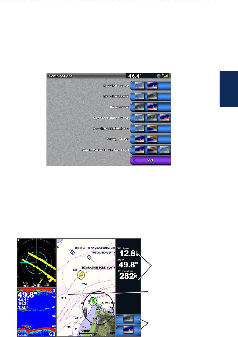
Using Combinations
Use the Combinations screen to view a combination of different screens at the same time. The
number of options available on the Combinations screen depends on the optional network devices
you have connected to your chartplotter, and whether you are using an optional BlueChart g2
Vision SD card. You can combine two or three screens (GPSMAP 4000 series) or up to four screens
(GPSMAP 5000 series).
To access the Combinations screen from the Home screen, select Combinations.
Combinations Screen
The Combinations screen shows a list of possible screen combinations. When viewing three
combination screens, one screen is larger than the others. The charts are numbered with a
corresponding button in the lower-right corner (GPSMAP 4000 series). To switch the larger screen,
select the icon from the lower-right corner that represents the screen you want (GPSMAP 4000
series) or touch Menu > Change Combination (GPSMAP 5000 series). Touch one of the screens
to select a single-screen combination page that will provide congurable data elds (GPSMAP 5000
series).
Data elds
Navigation Chart, Radar, and Sonar Combination
(GPSMAP 4000 series)
Focus screen
(GPSMAP 4000 series)
Select to switch focus
screen (GPSMAP 4000
series only)
To access additional settings or options for the Combinations screen, select Menu.
20 GPSMAP
®
4000/5000 Series Owner’s Manual
Using Combinations
Using
Combinations
To customize the screen combinations:
1. While viewing the Combinations screen, select Menu > Change Combination, or, from the
Home screen, select Combinations > Unused Combo (if one is available).
Combination
screen 1
Combination
screen 2
Data bar
Select the number of
combination screens
Change combination
screen 1
Change combination
screen 2
Toggle the
data bar
Change to vertical or
horizontal layout
2. Select Functions to select the number of combination screens, select Data Bar to toggle the
data bar on or off, and select a numbered button such as 1. Nav Chart in the example above to
select the combination screens to view.
3. Select Done.
NOTE: You can only choose from the options available to your unit. To increase the number of screens
available, use a BlueChart g2 Vision SD card or add network devices.
To add additional data elds:
1. While viewing the Combinations screen, press the soft key corresponding to an unused data eld
(GPSMAP 4000 series) or touch an unused data eld (GPSMAP 5000 series).
Adding a Data Field (GPSMAP 4000 series)
New data eld
2. Select the Digital Item to be displayed on the Combinations Screen. Available options vary, based
on the network conguration and the unit.
To edit an existing data eld:
While viewing the Combinations screen, press a soft key corresponding to a data eld (GPSMAP
4000 series) or touch a data eld (GPSMAP 5000 series). Select the item to be displayed.
To change the layout to horizontal or vertical:
1. While viewing the Combinations screen, select Menu > Change Combination.
2. Select Layout Vert. or Layout Horiz.
GPSMAP
®
4000/5000 Series Owner’s Manual 21
Where To?
Where
To?
Where To?
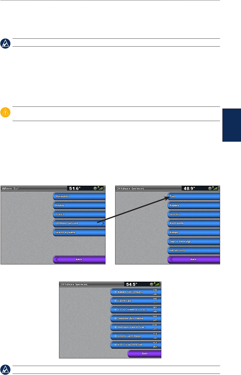
Use the Where To? option on the Home screen to search for, and navigate to, waypoints, routes, and
services such as nearby fuel, repairs, and ramps.
NOTE: You must create waypoints and routes before you can navigate to them.
You can navigate to a destination using one of three methods: Go To, Route To, or Guide To.
Go To—takes you directly to the destination.
Route To—creates a route from your location to a destination, allowing you to add turns to the
route.
Guide To—searches BlueChart g2 Vision chart data to suggest the best path to your destination.
You must be using a BlueChart g2 Vision SD card for this option to appear.
CAUTION: Guide To does not ensure obstacle and bottom clearance. For safety, always resolve any
discrepancies or questions before continuing navigation.
Navigating to a Destination
You can search for, and navigate to, waypoints, routes, and services such as nearby fuel, repairs, and
ramps.
To begin navigating:
1. From the Home screen, select Where To?.
2. Select the category to which you want to navigate.
3. Select a destination.
NOTE: Select Next Page to view additional information or to display the location on a chart.
•
•
•
22 GPSMAP
®
4000/5000 Series Owner’s Manual
Where To?
Where
To?
4. Select Navigate To.
5. Select Go To.
OR
Select Guide To when using a preprogrammed BlueChart g2 Vision card to use Auto Guidance.
6. Follow the colored line on the screen to the destination.
To stop navigating:
From the Navigation chart, select Menu, and then select Stop Navigation.
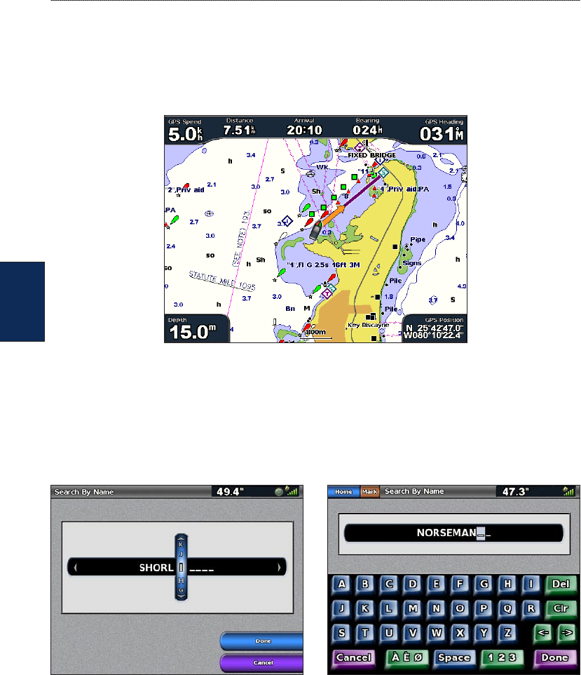
To search for a destination by name:
1. From the Home screen, select Where To? > Search by Name.
2. Use the ROCKER (GPSMAP 4000 series) or touch the onscreen keyboard (GPSMAP 5000
series) to select characters and spell at least a portion of the name of your destination.
Search - GPSMAP 4000 series Search - GPSMAP 5000 series
3. Select Done to view the 50 nearest destinations that contain your search criteria.
4. Select the best location, then select Navigate To > Go To or Route To (or Guide To when using
a preprogrammed BlueChart g2 Vision card).
GPSMAP
®
4000/5000 Series Owner’s Manual 23
Where To?
Where
To?
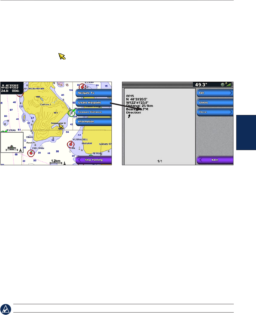
Creating and Using Waypoints
You can store up to 1,500 waypoints with a user-dened name, symbol, depth, and water
temperature for each waypoint.
To create a new waypoint:
1. From the Home screen, select Charts > Navigation Chart.
2. Use the map pointer ( ) (GPSMAP 4000 series) to select the location you want to designate as
a waypoint, or touch the location (GPSMAP 5000 series) you want to designate as a waypoint.
3. Select Create Waypoint.
4. Select one of the following:
Edit—designate a specic name, symbol, water depth, water temperature, position, or make a
comment about the waypoint.
Delete—delete the waypoint.
Move—change the location of the waypoint, either by selecting a different location on the map
or by entering grid coordinates.
To mark your current location as a waypoint:
From any screen, press the MARK key (GPSMAP 4000 series) or touch Mark (GPSMAP 5000
series).
Edit—designate a specic name, symbol, water depth, or water temperature.
Delete—deletes the waypoint.
Move—change the location of the waypoint, either by selecting a different location on the map
or by entering grid coordinates.
Man Overboard—designates the current location as a Man Overboard location.
Next Page/Previous Page—switches between waypoint information and the navigation chart.
NOTE: Selecting Mark creates a waypoint only at your present location.
To mark an MOB (Man Overboard) location:
When you mark a waypoint, you can designate it as an MOB (Man Overboard). This marks the
point and sets a course back to the marked location. When an MOB is active, an MOB waypoint
with an international MOB symbol is created, and the unit is on an active navigation to that point.
1. At any time, press the MARK key (GPSMAP 4000 series) or touch Mark (GPSMAP 5000 series).
2. Select Man Overboard.
•
•
•
•
•
•
•
•
24 GPSMAP
®
4000/5000 Series Owner’s Manual
Where To?
Where
To?
To edit an existing waypoint:
1. From the Navigation chart, use the map pointer ( ) (GPSMAP 4000 series) or touch the
waypoint (GPSMAP 5000 series) to highlight the waypoint on the Navigation chart.
OR
From the Home screen, select Information > User Data > Waypoints.
2. Select the waypoint you want to edit.
3. Select Edit.
4. Select the waypoint attribute you want to change (Name, Symbol, Depth, Water Temp) or add a
comment.
To move the waypoint on the Navigation chart:
1. Select the waypoint on the navigation chart.
2. Select Review. (The Review button is only shown when more than one waypoint is in the
vicinity.)
3. Select the button for the waypoint you want to edit.
4. Select Move.
5. Select Use Chart or Enter Position.
6. If entering position coordinates, use the ROCKER (GPSMAP 4000 series) or the keyboard
(GPSMAP 5000 series) to enter the new position for the waypoint. If using the chart, highlight the
new location with the map pointer ( ) (GPSMAP 4000 series) or touch the location (GPSMAP
5000 series), and select Move Waypoint. The waypoint moves to the new location.
To view a list of all waypoints:
From the Home screen, select Information > User Data > Waypoints.
To delete a waypoint or MOB:
1. From the Navigation chart, use the map pointer ( ) (GPSMAP 4000 series) or touch the
waypoint (GPSMAP 5000 series) to highlight the waypoint on the Navigation chart.
OR
From the Home screen, select Information > User Data > Waypoints.
2. Select the waypoint or MOB you want to delete.
3. Select Review > Delete.
GPSMAP
®
4000/5000 Series Owner’s Manual 25
Where To?
Where
To?
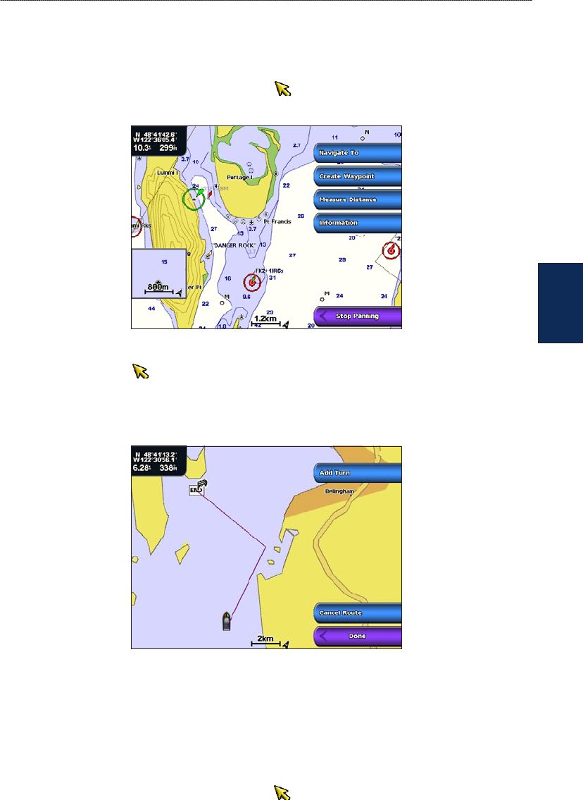
Creating and Using Routes
You can create and store up to 20 routes with up to 250 waypoints each.
To create a route from your present location:
1. From the Navigation chart, use the map pointer ( ) (GPSMAP 4000 series) or touch your
destination (GPSMAP 5000 series) to select your destination.
2. Select Navigate To > Route To.
3. Use the map pointer ( ) (GPSMAP 4000 series) to select the location at which you want to
make the last turn, or touch the location (GPSMAP 5000 series) at which you want to make the
last turn toward your destination.
4. Select Add Turn.
5. To add additional turns, select the point at which you want to make the turn (working backward
from the destination) and select Add Turn.
6. Select Done to nish the route, or select Cancel Route to delete the route.
To create a route in another location:
1. From the Home screen, select Information > User Data > Routes > New Route > Use Chart.
2. Select Use Chart or Use Waypoint List.
3. If you selected Use Chart, use the map pointer ( ) (GPSMAP 4000 series) or touch the
location (GPSMAP 5000 series) to select the initial location at which you want to start the new
route. If you selected Use Waypoint List, select the rst waypoint on the route.
4. Select Add Turn to mark the starting point of the route.
5. Choose the location of the rst turn and select Add Turn. Repeat until the route is complete.
6. Select Done.
26 GPSMAP
®
4000/5000 Series Owner’s Manual
Where To?
Where
To?
To create a route using Auto Guidance (when using a preprogrammed BlueChart g2
Vision card):
1. From the Navigation chart, select your destination.
2. Select Navigate To > Guide To. Your route is calculated.
NOTE: You can change the auto guidance path to a route by selecting the end of the path and selecting
Navigate To > Route To. The auto guidance path stays on the screen, allowing you to trace it while
creating a route.
To edit a route:
1. From the Home screen, select Information > User Data > Routes.
2. Select the route to edit.
3. Select Review > Edit Route. You can edit the route name or edit the route turns.
To delete a route:
1. From the Home screen, select Information > User Data > Routes.
2. Select the route to edit.
3. Select Review > Delete.
To bypass a waypoint on a route:
1. Create a route as previously described.
2. Select the waypoint that follows the waypoint you are bypassing.
3. Select Navigate To > Go To (or Route To).
Navigating with a Garmin Autopilot
When you start any type of navigation (Go To, Route To, Guide To, or Follow Track), if you are
connected to a compatible Garmin autopilot (such as a Garmin GHP
™
10), you will be prompted to
engage the autopilot.
GPSMAP
®
4000/5000 Series Owner’s Manual 27
Viewing Information
Viewing
Information
Viewing Information
Use the Information screen to access information about tides, currents, celestial data, user data, other
boats, gauges, and video.
Viewing Tide Station Information
To view tide information from the Home screen, select Information > Tides/Currents > Tides.
Information for the most-recently viewed tide station is shown.
Select Nearby Stations to view other stations close to your current location. Select Change
Date > Manual to view tide information for a different date.
Viewing Current Information
Use the Current Prediction screen to view information for currents.
NOTE: You must use a BlueChart g2 Vision card to view Current Station information.
To view current information from the Home screen, select Information > Tides/Currents >
Currents. Information for the most-recently viewed current station is shown.
Select Nearby Stations to view other stations close to your current selection. Select Change
Date > Manual to view current information for a different date.
Select Show Report to view the Current Report for the selected station.
28 GPSMAP
®
4000/5000 Series Owner’s Manual
Viewing Information
Viewing
Information
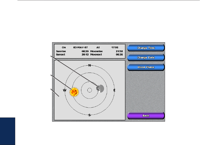
Viewing Celestial Information
Use the Celestial screen to view celestial data for sunrise, sunset, moonrise, moonset, moon phase,
and approximate sky view location of the sun and moon.
To view celestial information from the Home screen, select Information > Tides/Currents >
Celestial.
Moon position
Sun position
Sky view window
Viewing User Data
To view user data, from the Home screen, select Information > User Data.
Waypoints—view a list of all saved waypoints (page 23).
Tracks—view and manage tracks (page 12).
Routes—view a list of saved routes (page 25).
Data Transfer—transfer waypoints, routes, and tracks to and from an SD card or network.
Clear User Data—erase all user waypoints, routes, and tracks.
To copy or merge MapSource data to your chartplotter:
1. Insert the SD card into your chartplotter to allow it to place a le on the SD card. This le provides
information to MapSource to format the data. This only needs to be done the rst time you copy
or merge MapSource data to your chartplotter from a specic SD card.
2. Check your MapSource version on the computer by clicking Help > About MapSource. If the
version is older than 6.12.2, update to the most current version by clicking Help > Check for
Software Updates or check the Garmin Web site at www.garmin.com.
3. Insert the SD card into an SD card reader that is attached to the computer.
4. From within MapSource, click on Transfer > Send to Device.
5. From the Send to Device window, select the drive for the SD card reader and the types of data
you want to copy to your chartplotter.
6. Click Send.
7. Insert the SD card into your chartplotter.
8. From the Home screen on your chartplotter, select Information > User Data > Data Transfer >
Card.

GPSMAP
®
4000/5000 Series Owner’s Manual 29
Viewing Information
Viewing
Information
9. Complete one of the following:
Select Merge From Card to transfer data from the SD card to the unit and combine it with
existing user data.
Select Replace From Card to overwrite the data on your unit.
10. Select the le name from the list.
11. Select Merge from Card or Replace from Card.
To transfer data (waypoints, routes, tracks) to an SD card:
1. Insert an SD card into the SD card slot on the front of the unit.
2. From the Home screen, select Information > User Data > Data Transfer > Card > Save To
Card.
3. Complete one of the following:
Select the le name from the list.
Select Add New File to create a new le. Enter the le name using the ROCKER (GPSMAP
4000 series) or onscreen keyboard (GPSMAP 5000 series) and select Done.
4. Select Save To Card to save waypoints, routes, and tracks to the SD card. The le name is
saved with an .ADM extension.
To transfer data (waypoints, routes, tracks) from an SD card:
1. Insert an SD card into the SD card slot on the front of the unit.
2. From the Home screen, select Information > User Data > Data Transfer > Card.
3. Complete one of the following:
Select Merge From Card to transfer data from the SD card to the unit and combine it with
existing user data.
Select Replace From Card to overwrite items on your unit.
4. Select the le name from the list.
5. Select Merge from Card or Replace from Card.
To copy the built-in maps to an SD card:
1. Insert an SD card into the SD card slot on the front of the unit.
2. From the Home screen, select Information > User Data > Data Transfer > Card.
3. Select Copy Built-In Map to copy the maps loaded onto your unit to the SD card.
To transfer data to or from a network:
1. Connect the unit to a Garmin Marine Network using the network port on the back of the unit and
a Garmin Network cable.
2. From the Home screen, select Information > User Data > Data Transfer > Network.
Complete one of the following:
Select Clone User Data to transfer waypoints, routes, and tracks to other chartplotters
connected to the network. Existing data will be overwritten on those chartplotters.
Select Merge User Data to transfer data between all the chartplotters connected to the
network. Unique data will be combined with existing data on every chartplotter.
To back up data to a computer:
1. Insert an SD card into the SD card slot on the front of the unit.
2. From the Home screen, select Information > User Data > Data Transfer > Card > Save To
Card.
3. Complete one of the following:
Select the le name from the list.
•
•
•
•
•
•
•
•
•
30 GPSMAP
®
4000/5000 Series Owner’s Manual
Viewing Information
Viewing
Information
Select Add New File to create a new le. Enter the le name using the ROCKER (GPSMAP
4000 series) or onscreen keyboard (GPSMAP 5000 series) and select Done.
4. Select Save To Card. The le name is saved with an .ADM extension.
5. Remove the SD card from the unit and insert it into an SD card reader attached to a computer.
6. From Windows® Explorer, open the Garmin\UserData folder on the SD card.
7. Copy the appropriate .ADM le on the card and paste it to any location on the computer.
To restore backup data to your chartplotter:
1. Copy the appropriate .ADM le from the computer to an SD card in the Garmin\UserData folder.
2. Insert the SD card into your chartplotter.
3. From the Home screen on your chartplotter, select Information > User Data > Data Transfer >
Card > Replace From Card.
To delete all waypoints, routes, and tracks:
1. From the Home screen on your chartplotter, select Information > User Data > Clear User Data.
2. Select Waypoints, Routes, Saved Tracks, or All.
3. Select OK or Cancel.
Viewing the DSC List
The DSC List is a log of the most-recent DSC calls and other DSC contacts you have entered. The
DSC List can contain up to 100 entries. The DSC List shows the most-recent call from a boat. If
a second call is received from the same boat, it replaces the rst call in the Call List. For more
information on DSC, see page 49. To view the DSC List, from the Home screen, select Information
> DSC List.
NOTE: Your unit must be connected to a VHF radio that supports DSC (Digital Selective Calling) in
order to view the DSC List.
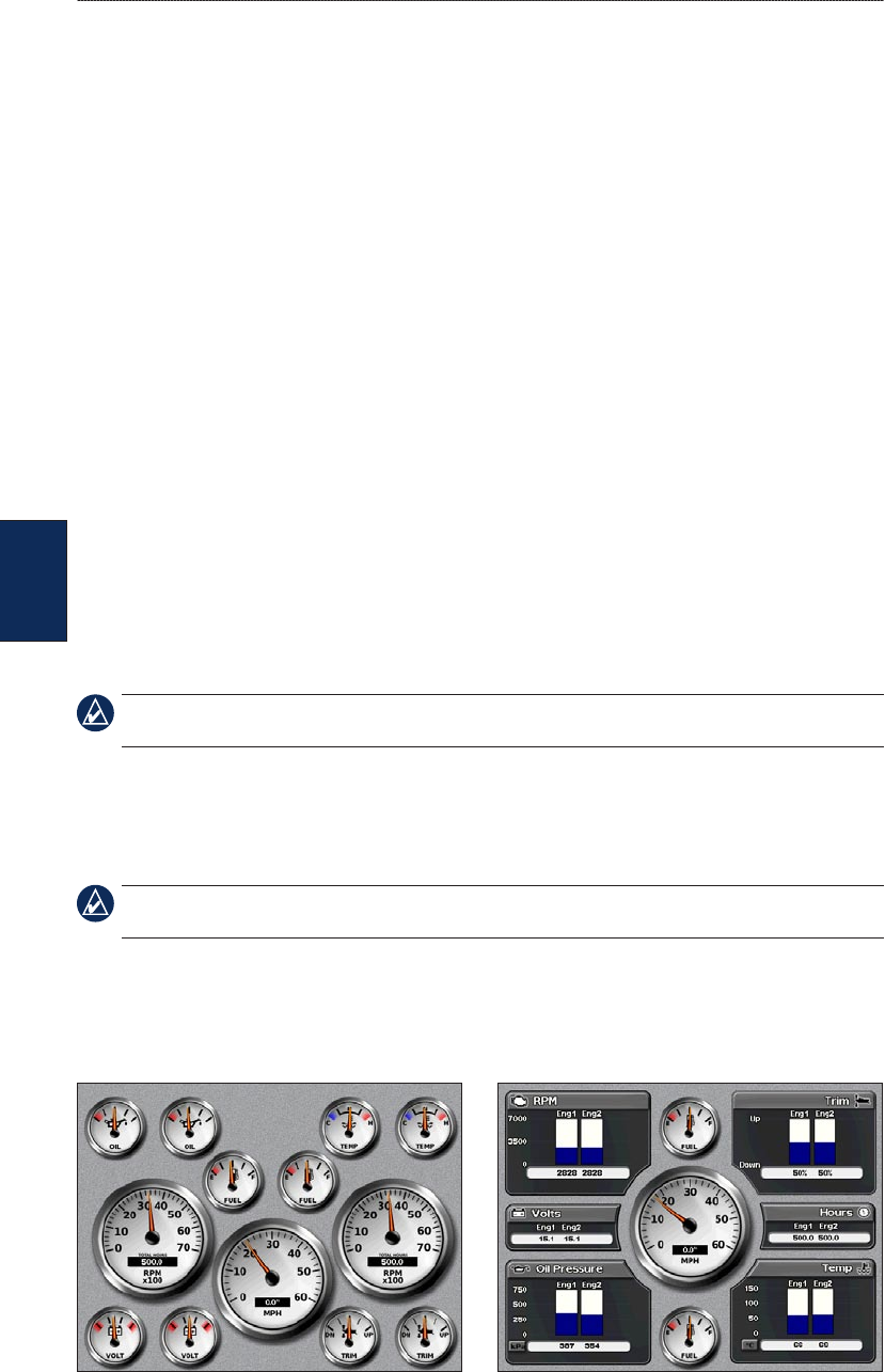
Viewing Engine Gauges
For more than two engines, you can only use the digital gauges. For one or two engines, you can
switch between analog and digital gauges.
NOTE: You must be connected to a NMEA 2000 network capable of sensing engine data in order to
view the gauges. See the GPSMAP 4000/5000 Series Installation Instructions for details.
To select analog or digital gauges:
1. To view analog or digital engine gauges from the Home screen, select Information > Dashboard
Gauges > Engine > Menu.
2. Select Analog or Digital.
•

GPSMAP
®
4000/5000 Series Owner’s Manual 31
Viewing Information
Viewing
Information
Viewing Fuel Gauges
To view fuel gauges from the Home screen, select Information > Dashboard Gauges > Fuel. Fuel
ow for each engine, total fuel ow, fuel level in each tank, total fuel remaining, fuel economy,
engine trim, boat speed, engine RPM, and the range for your boat are displayed.
NOTE: To view fuel information, your unit must be connected to an external fuel sensor, such as the
Garmin GFS™ 10.
To synchronize your fuel gauges with your fuel:
From the Home screen, select Information > Dashboard Gauges > Fuel > Menu.
Fill Up All Tanks—select when your tank is full. An estimate of the total fuel is shown. Adjust
if necessary.
Add Fuel To Boat—select when you have added less than a full tank. An estimate of the fuel
added is shown. Adjust if necessary.
Set Total Fuel Onboard—select to specify the total fuel in your tanks.
Fuel Economy—select either GPS Speed or Water Speed (using data from a speed wheel)
for the fuel economy calculation.
Viewing Video
Your unit can display video if you connect it to a video source using the supplied video cable. See
the GPSMAP 4000/5000 Series Installation Instructions for details.
To view video from the Home screen, select Information > Video.
Select Menu to set up the following:
Source—selects the video device (1 or 2) to use to display video. If you have two video sources
and want to alternate between the two, select Alternate to dene the amount of time each video
is displayed.
Aspect—switches between the standard aspect ratio and a stretched aspect ratio. The video
cannot be stretched beyond the dimensions provided by the connected video device. Because of
this, the stretched video may not ll the entire screen of the GPSMAP 4012/5012.
Brightness—adjusts the brightness of the video feed up or down, or select Auto to allow the unit
to automatically adjust the brightness.
Saturation—adjusts the color saturation up or down, or select Auto to allow the unit to
automatically adjust the saturation.
Contrast—adjusts the contrast up or down, or select Auto to allow the unit to automatically
adjust the contrast.
Standard—selects the video format used by the source (PAL or NTSC). Select Auto to let the
unit automatically select the source format.
WARNING: Do not attempt to operate or watch video input while operating or navigating your boat.
Operating or watching the video input while the boat is moving could cause an accident or collision
resulting in property damage, serious injury, or death.
•
•
•
•
•
•
•
•
•
•

32 GPSMAP
®
4000/5000 Series Owner’s Manual
Conguring the Chartplotter
Conguring the
Chartplotter
Conguring the Chartplotter
Use the Congure screen to congure unit settings.
Conguring System Settings
To change general system settings from the Home screen, select Congure > System.
Simulator—turn Simulator Mode On or Off. Select Setup to set simulator options. (If you set the
unit into a Store Demonstration mode during the initial unit setup, this setting is named Demo.)
Auto Power Up (GPSMAP 4010 and GPSMAP 5015 only)—turn Auto Power Up On or Off. When
On is selected, the chartplotter will automatically turn on whenever power is applied, unless the
chartplotter is turned off with the Power key before power is lost.
Beeper/Display—select Beeper to set when the unit makes audible sounds. Select Backlight to
brighten or darken the backlight. Select Color Mode to switch between Day Mode and Night Mode.
Select Screenshot Capture to turn the screenshot capture feature on or off (page 54).
GPS—view GPS satellites.
System Information—view system information, reset factory settings, view the status of networked
devices, and display the event log. The event log displays a list of system events. Select the event
to view additional information. The Save to Card button is provided as a troubleshooting tool; a
Garmin Product Support representative may ask you to use this to retrieve data about the marine
network.
Radar Diagnostics (if radar is connected)—a troubleshooting tool used by installers.
Changing the System Language
To change the system language, from the Home screen, select Congure > Preferences >
Language and then select the language.
Conguring Navigation Preferences
To change navigation preferences, from the Home screen, select Congure > Preferences >
Navigation.
Route Labels—for saved routes, this determines whether route turns are indicated by number (Turn
1, Turn 2, and so on) or by waypoint name, or whether the description of turns is hidden.
Turn Transition—set how much time or how far before a turn in a route that you transition to the
next leg. Raising this value can help improve the accuracy of the autopilot when navigating a route
or automatic-guidance line with many frequent turns or at higher speeds. For straighter routes or
slower speeds, lowering this value can improve autopilot accuracy.
Speed Sources—specify the sensor used for Wind numbers and Fuel Economy. Touch Wind or Fuel
Economy to toggle between Water (from a water-speed sensor) and GPS (from the calculated GPS
speed).
GPSMAP
®
4000/5000 Series Owner’s Manual 33
Conguring the Chartplotter
Conguring the
Chartplotter
Conguring Units of Measure
To change units of measure from the Home screen, select Congure > Preferences > Units.
System Units—global setting that denes individual units of measure at the same time. Statute
(mh, ft, ºF), Metric (kh, m, ºC), Nautical (kt, ft, ºF), or Custom. Select Custom to individually
dene units of measure for depth, temperature, distance, speed, elevation, volume, and pressure.
NOTE: You must be receiving NMEA sonar depth data or using a Garmin sounder module to view
depth and water temperature information.
Heading—sets the reference used in calculating heading information.
Auto Mag Var—Automatic Magnetic Variation automatically sets the magnetic declination for
your location.
True—sets true north as the heading reference.
Grid—sets grid north as the heading reference (000º).
User Mag Var—allows you to set the magnetic variation value.
Position Format—change the coordinate style in which a given location reading appears. Do not
change the position format unless you are using a map or chart that species a different position
format.
Map Datum—change the coordinate system in which the map is structured. Do not change the Map
Datum unless you are using a map or chart that species a different Map Datum.
Time—set the time options.
Time Format—select 12-hour, 24-hour, or UTC time format.
Time Zone—set the time zone you want displayed for time readings.
Daylight Saving Time—indicate whether you want daylight saving time Off, On, or Auto. The
auto setting automatically turns daylight saving time on or off, depending on the time of year.
Conguring Communications Settings
To change the communications settings from the Home screen, select Congure >
Communications.
NMEA 0183 Setup—enable or disable NMEA 0183 output sentences for sounder, route, system,
and Garmin NMEA settings.
Port Types—congure the input/output format for each port to use when connecting your
chartplotter to external NMEA devices, a computer, or other Garmin devices. NMEA Std.
supports the input or output of standard NMEA 0183 data, DSC, and sonar NMEA input support
for the DPT, MTW, and VHW sentences. NMEA High Speed supports the input or output of
standard 0183 data for most AIS receivers. The Garmin option supports the input or output of
Garmin-proprietary data for interfacing with Garmin software.
Posn. Precision—adjust the number of digits (Two Digits, Three Digits, or Four Digits) to the
right of the decimal point for transmission of NMEA output.
Waypoint IDs—determine how the unit outputs waypoint identiers (Names or Numbers).
Defaults—reset NMEA 0183 settings to their default settings (OK or Cancel).
Diagnostics—a tool used by installers to verify that NMEA 0183 data is being sent across the
system.
•
•
•
•
•
•
•
•
•
•
•
•

34 GPSMAP
®
4000/5000 Series Owner’s Manual
Conguring the Chartplotter
Conguring the
Chartplotter
To enable or disable NMEA 0183 output sentences:
1. From the Home screen, select Congure > Communications > NMEA 0183 Setup > Output
Sentences.
2. Select a setting (Sounder, Route, System, or Garmin).
3. Select the NMEA 0183 output sentence.
4. Select Off to disable, or select On to enable, the NMEA 0183 output sentence.
NMEA 2000 Setup—view and congure the devices connected to the NMEA 2000 network and set
bridging to On, Off, or Auto.
Device List—lists the NMEA 2000 devices on your network. If a NMEA 2000 device has
conguration options or settings, select the device for a list of options.
Output Bridging—output bridging occurs when a chartplotter takes NMEA 0183 data it receives
from any source, formats it into NMEA 2000 data, and then sends it over the NMEA 2000 bus.
Select On or Off to enable or disable this function for the chartplotter. Select Auto to allow the
chartplotters on the network to negotiate with each other to determine which chartplotter will
perform this function. There should not be more than one chartplotter on the network bridging
NMEA 0183 data over the NMEA 2000 bus.
Wireless Devices—allows wireless devices, such as a remote control or optical mouse to
communicate with the chartplotter.
Preferred Sources—allows selection of a preferred device when more than one source is available
for the same function.
Marine Network—review all connected Garmin Marine Network devices. See page 37.
Setting Alarms
You can set the unit to sound an audible alarm when certain conditions are met. By default, all
alarms are turned off.
To set an alarm:
1. From the Home screen, select Congure > Alarms.
2. Select an alarm category.
3. Select an alarm.
4. Select On to turn the alarm on, and then specify alarm information.
Setting Navigation Alarms
To set a navigation alarm, from the Home screen, select Congure > Alarms > Navigation.
Arrival—set an alarm to sound when you are within a specied distance or time from a turn or
destination waypoint.
Type—select whether you want arrival alarms to sound only when nearing destinations or when
nearing turns and destinations. Set to Off to disable arrival alarms.
Activation—select whether the arrival alarm triggers on time to arrival or distance to arrival.
Change Time/Change Distance—if you have Activation set to Time, select Change Time to set
the number of minutes before arrival that the alarm should sound. If you have Activation set to
Distance, select Change Distance to set the distance before arrival that the alarm should sound.
Use the ROCKER (GPSMAP 4000 series) or onscreen keyboard (GPSMAP 5000 series) to
change the time or distance.
•
•
•
•
•
GPSMAP
®
4000/5000 Series Owner’s Manual 35
Conguring the Chartplotter
Conguring the
Chartplotter
Anchor Drag—set an alarm to sound when you exceed a specied drift distance.
Off Course—set an alarm to sound when you are off course by a specied distance.
Setting System Alarms
To set a system alarm, from the Home screen, select Congure > Alarms > System.
Clock—set an alarm using the system (GPS) clock. The unit must be on for the clock alarm to work.
Battery—set an alarm to sound when the battery reaches a user-determined low voltage.
GPS Accuracy—set an alarm to sound when the GPS location accuracy falls outside the user-
determined value.
Setting Sonar Alarms
To set a sonar alarm, from the Home screen, select Congure > Alarms > Sonar.
NOTE: You must have an optional sonar module (and a transducer connected to the sounder module)
wired through NMEA 0183 or connected to the Garmin Marine Network to receive sonar information.
Shallow Water—set an alarm to sound when the depth is less than the specied value.
Deep Water—set an alarm to sound when the depth is greater than the specied value.
Water Temp—set an alarm to sound when the transducer reports a temperature that is 2°F (1.1°C)
above or below the specied temperature.
Fish—set an alarm to sound when the unit detects a suspended target of the specied symbols.
— sounds an alarm for all sh sizes
— sounds an alarm for medium and large sh only
— sounds an alarm for large sh only
Setting the Total Fuel Onboard Alarm
You can congure your chartplotter to sound an alarm when the total amount of remaining onboard
fuel reaches the level you specify.
NOTE: To receive fuel-level information, your unit must be connected to an external fuel sensor, such
as the Garmin GFS 10.
To enable the Total Fuel Onboard alarm and set the fuel alarm level:
1. From the Home screen, select Congure > Alarms > Fuel > Total Fuel Onboard > On.
2. Use the ROCKER (GPSMAP 4000 series) or onscreen keyboard (GPSMAP 5000 series) to
indicate the fuel level at which the alarm should sound.
To disable the Total Fuel Onboard alarm:
From the Home screen, select Congure > Alarms > Fuel > Total Fuel Onboard > Off.
Conguring My Boat
To congure settings for your boat, from the Home screen, select Congure > My Boat.
Auto Guidance—set the Auto Guidance parameters for your boat:
Safe Depth—set the minimum depth (chart depth datum) to allow when calculating an auto
guidance path. A safe depth of less than one meter is not allowed when using Auto Guidance.
•
36 GPSMAP
®
4000/5000 Series Owner’s Manual
Conguring the Chartplotter
Conguring the
Chartplotter
Safe Height—set the minimum height (chart height datum) of a bridge that your boat can safely
travel under.
Shoreline Distance—set how close you want to travel near the shore: Nearest, Near, Normal,
Far, or Farthest. This is used by the automatic guidance calculation to determine how close
to the shoreline you want the automatic-guidance line to be. Changing this while navigating an
automatic-guidance line will recalculate the path.
Keel Offset—offset the surface reading for the depth of a keel, making it possible to measure depth
from the bottom of the keel instead of from the transducer location. Enter a positive number to offset
for a keel. Enter a negative number to offset for a large vessel that may draw several feet of water.
To adjust the Keel Offset:
1. From the Home screen, select Congure > My Boat > Keel Offset.
2. Use the ROCKER (GPSMAP 4000 series) or the onscreen keyboard (GPSMAP 5000 series) to
specify the offset.
3. Select Done to accept the number.
NOTE: Select Cancel to cancel your changes and return to the My Boat screen.
Temp Offset—set the temperature offset for the temperature sensor of your transducer.
Calibrate Water Speed—use this menu to calibrate a speed-sensing device. Follow the on-screen
directions for calibration. If you do not have a speed-sensing device, this menu does not appear.
NOTE: If the boat is not moving fast enough or the speed sensor is not registering a speed, a “Speed
Too Low” message appears. Select OK and safely increase boat speed. If you get the message again,
stop the boat and make sure the speed-sensor wheel is not stuck. If the wheel turns freely, check the
cable connections. If you continue to get the message, contact Garmin Product Support.
Fuel Capacity—enter the total fuel capacity of your boat.
Conguring Other Vessels
To congure settings for boats other than your own, from the Home screen, select Congure >
Other Vessels.
AIS—turn AIS (Automatic Identication System) on or off. AIS alerts you to area trafc by
providing boat IDs, position, course, and speed for boats that are within range and equipped with a
transponder.
DSC—turn DSC (Digital Selective Calling) on or off.
NOTE: To congure AIS or DSC information for other boats, your unit must be connected to an
external AIS or DSC device.
Collision Alarm (AIS and MARPA only)—turn a safe zone around your boat on or off. This is used
for collision avoidance, and can be customized.
To customize safe-zone settings:
From the Home screen, select Congure > Other Vessels > Collision Alarm.
Range—change the measured radius of the safe-zone ring to a specied distance from 500 ft.
to 2.0 nm (or from 150 m to 3.0 km, or from 500 ft. to 2.0 mi).
Time to (Safe Zone)—sounds an alarm if AIS or MARPA determines that a target will intersect
the Safe Zone within the dened time interval (ranging from 1 to 24 minutes).
•
•
•
•

GPSMAP
®
4000/5000 Series Owner’s Manual 37
Using the Garmin Marine Network
Marine
Network
Using the Garmin Marine Network
The Garmin Marine Network allows you to share data from Garmin peripheral devices between
Garmin chartplotters quickly and easily. You can connect your GPSMAP 4000 series and GPSMAP
5000 series chartplotters, and previous Garmin Marine Network compatible chartplotter models
(GPSMAP 3005/3006/3010), to your network to share data. With the Garmin Marine Network, you
can:
Share GPS data from a GPS 17 antenna that is wired to one chartplotter, with every chartplotter
connected to the Garmin Marine Network.
Share NMEA 0183 data from devices that are wired to one chartplotter, with every chartplotter
connected to the Garmin Marine Network.
NOTE: Both the GPS 17 and any NMEA 0183 devices must be connected to the same chartplotter to
achieve the best results when sharing data over the Garmin Marine Network.
NOTE: If you are using a GSD 21 wired to a GPSMAP 3006/3010 chartplotter, data is shared with
any GPSMAP 4000 series and GPSMAP 5000 series chartplotters connected to your Garmin Marine
network. All GSD 21 settings must be congured on the GPSMAP 3006/3010. You cannot wire a GSD
21 to a GPSMAP 4000 series or GPSMAP 5000 series chartplotter.
Share data from Garmin Marine Network devices connected to any chartplotter in the Marine
Network or to a GMS 10 Marine Network Port Expander, with every other chartplotter connected
to the Marine Network. These devices include:
GSD 22 digital sounder—provides sonar data when connected to the Garmin Marine
Network and an appropriate transducer. Sonar data is shared by all chartplotters on the
network.
GMR 21/41 Radome; GMR 18 Radome; and GMR 404/406 Open Array Radar—
provide radar data when connected to the Garmin Marine Network. Radar data is shared by
all chartplotters on the network.
Share BlueChart g2 Vision cartography data from an SD card inserted in one GPSMAP 4000
or GPSMAP 5000 series chartplotter with every GPSMAP 4000 and GPSMAP 5000 series
chartplotter connected to the Marine Network.
NOTE: BlueChart g2 Vision cartography is only compatible with GPSMAP 4000 and GPSMAP 5000
series chartplotters. Previous Garmin Marine Network-compatible chartplotter models (such as the
GPSMAP 3010) can be connected to your network, but they cannot share BlueChart g2 Vision data.
Transfer waypoint, route, and track information from one chartplotter connected to the Garmin
Marine Network to every other chartplotter connected to the network. The data can be cloned
from one chartplotter to every other connected chartplotter, or the data can be merged and shared
with every connected GPSMAP 4000 and GPSMAP 5000 series chartplotter.
•
•
•
◦
◦
•
•
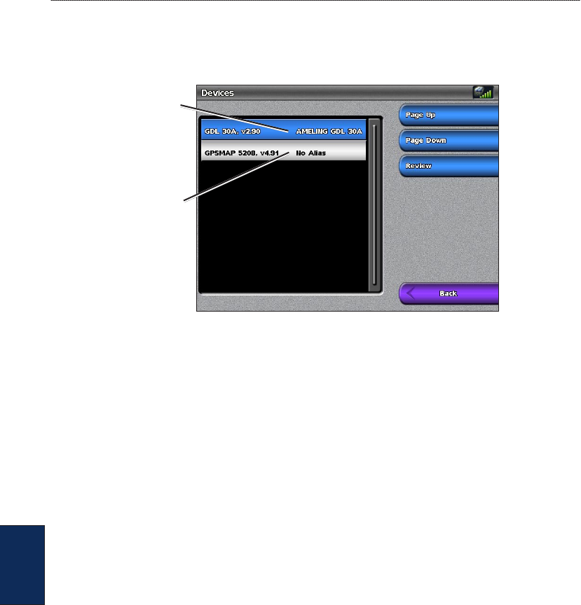
38 GPSMAP
®
4000/5000 Series Owner’s Manual
Using the Garmin Marine Network
Marine
Network
Viewing Connected Garmin Marine Network Devices
To view all connected Garmin Marine Network devices, from the Home screen, select Congure >
Communications > Marine Network.
Network Devices
No alias
dened
Alias
dened
Each connected device is listed along the left side of the screen. To assign an alias or name to one of
the devices for identication purposes, select the device and then select Review. Use the ROCKER
(GPSMAP 4000 series) or the onscreen keyboard (GPSMAP 5000 series) to name the device.
Select Back or press the HOME key to exit.

GPSMAP
®
4000/5000 Series Owner’s Manual 39
Using Radar
Using
Radar
Using Radar
When you connect your chartplotter to an optional Garmin marine radar such as a GMR 404/406
or a GMR 18, you can view more information about your surroundings. The Garmin marine radar
connects through the Garmin Marine Network and shares radar data with all networked chartplotters.
The Garmin marine radar transmits a narrow beam of microwave energy as it rotates in a 360º
pattern. When the transmitted energy contacts a target, some of that energy is reected back to the
radar.
WARNING: The marine radar transmits microwave energy that has the potential to be harmful to
humans and animals. Before beginning radar transmission, verify that the area around the radar is clear.
The radar transmits a beam approximately 12° above and 12° below a line extending horizontally from
the center of the radar. Avoid looking directly at the radar, because the eyes are the most susceptible part
of the body.
To turn on the radar:
1. When you power the network on, the radar warms up. A countdown is provided to alert you when
the radar is ready. From the Home screen, select Radar > Cruising for Cruising mode, or select
Radar > Sentry for Sentry mode. See page 40 for more information on Cruising and Sentry
modes.
NOTE: As a safety feature, the radar enters standby mode after it warms up. This gives you an
opportunity to verify that the area around the radar is clear before beginning radar transmission. The
microwave energy transmitted by the radar can potentially be harmful to humans and animals.
2. When the message “Ready to Transmit” appears, select Menu.
3. On the lower-right portion of the screen, select Transmit Radar. A “Spinning Up” message
appears for a few moments, then the radar begins painting an image.
To turn off the radar:
1. Press and release the Power key on the chartplotter (do not hold the button, or you may shut
down the chartplotter), or select Menu.
2. Select Radar to Standby.
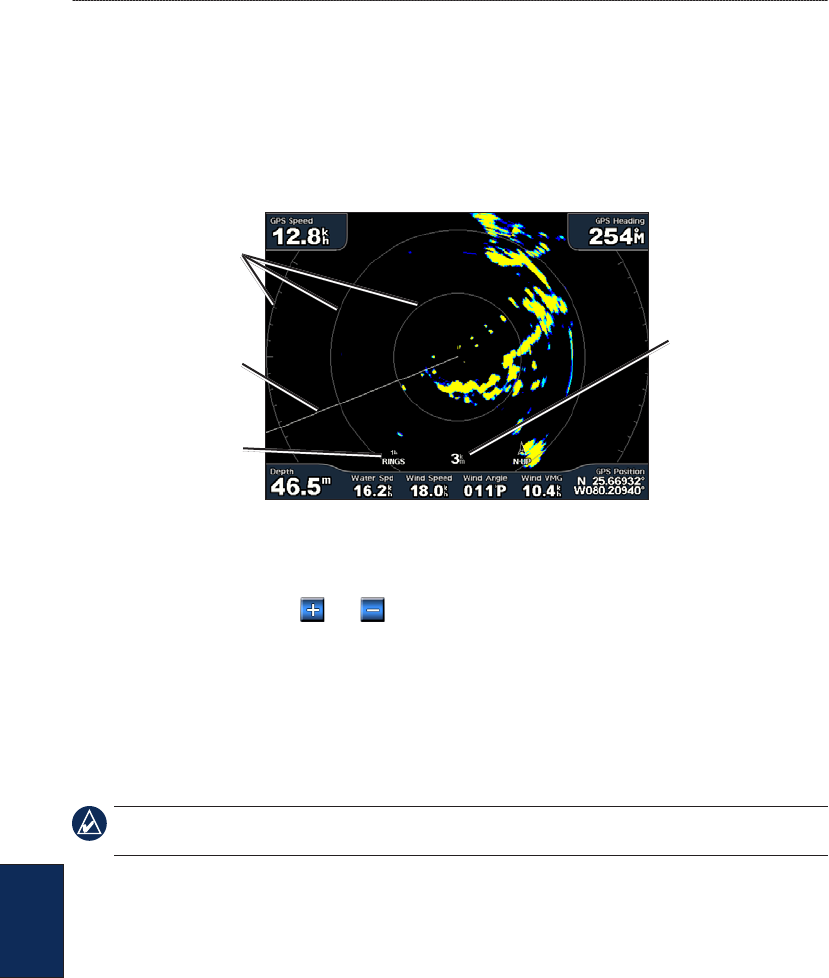
40 GPSMAP
®
4000/5000 Series Owner’s Manual
Using Radar
Using
Radar
Using Cruising Mode
Cruising mode is the standard radar operation. If you switch from Sentry mode to Cruising mode,
the antenna will go into full-time transmission and will disable any guard zones. You can place the
radar in Cruising mode by selecting Radar > Cruising.
Use the Cruising screen to view a full-screen image of the gathered radar information. Your position
is in the center of the screen, and the rings provide distance measurements.
Distance
between rings
Range rings
Heading line
Zoom scale
The zoom scale represents the distance from your position (the center) to the outermost ring. Each
ring represents an even division of the zoom scale. For example, if the zoom scale is set at three
kilometers, each ring represents one kilometer from the center out. Use the RANGE (+/-) keys
(GPSMAP 4000 series) or the and keys (GPSMAP 5000 series) to adjust the zoom scale.
Using Sentry Mode
Sentry mode allows you to put the radar antenna into timed-transmit mode, in which you can
congure a transmit/standby cycle. You can also enable a guard zone in Sentry mode, which
identies a safe zone around your boat. An alarm sounds when a radar object enters this zone. You
can place the radar in Sentry mode by selecting Radar > Sentry.
NOTE: When Sentry mode is enabled, all MARPA targets are cancelled, and you cannot acquire
MARPA targets until you exit Sentry mode.
To enable timed-transmit mode, select Menu > Sentry Setup > Timed Xmit.
To set the standby and transmit times:
1. From the Radar screen, select Menu > Sentry Setup.
2. Select Timed Xmit if it is set to off, and then select Stdby Time or Xmit Time.
3. Enter the time in minutes using the ROCKER (GPSMAP 4000 series) or the onscreen keyboard
(GPSMAP 5000 series), and then select Done.
To enable the guard zone from the Radar screen, select Menu > Sentry Setup > Enable Guard
Zone.
To adjust the guard zone boundaries:
1. While the guard zone is on, from the Radar screen, select Menu > Sentry Setup > Adjust
Guard Zone > Move Guard Zone.
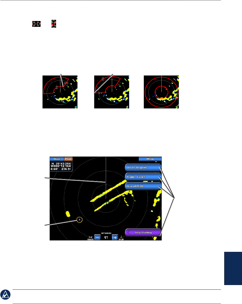
GPSMAP
®
4000/5000 Series Owner’s Manual 41
Using Radar
Using
Radar
2. Select from the following options:
Corner 1 (and Corner 2): Use the ROCKER (GPSMAP 4000 series) as indicated by the
arrows ( and ) to dene the size of the guard zone. Select Corner 1 or Corner 2 to
change the reference point. For GPSMAP 5000 series units, touch Corner 1, and then touch
the point on the screen at which you want the rst corner of the guard zone. Repeat this with
Corner 2.
Circular: Joins the guard zone to completely encompass the boat. Use Corner 1 or Corner 2
to adjust the size.
Corner 1 Corner 2 Circular
Radar Targeting
Use the ROCKER (GPSMAP 4000 series) or touch the target location (GPSMAP 5000 series) to
begin targeting. As you move the target over objects on the radar, target options appear along the
right side of the screen.
Cruising Screen - Targeting
Heading line
Target options
Target
To stop targeting, select Stop Pointing.
Create Waypoint—marks a waypoint at the targeted object or location.
Acquire Target—assigns a MARPA (Mini Automatic Radar Plotting Aid) tag to the targeted object.
NOTE: MARPA requires the use of a heading sensor. The heading sensor must output the NMEA 0183
sentence HDM or HDG.
Drop VRM/EBL—sets the Variable Range Marker (VRM) and Electronic Bearing Line (EBL) to
measure range and bearing to a target.
•
•
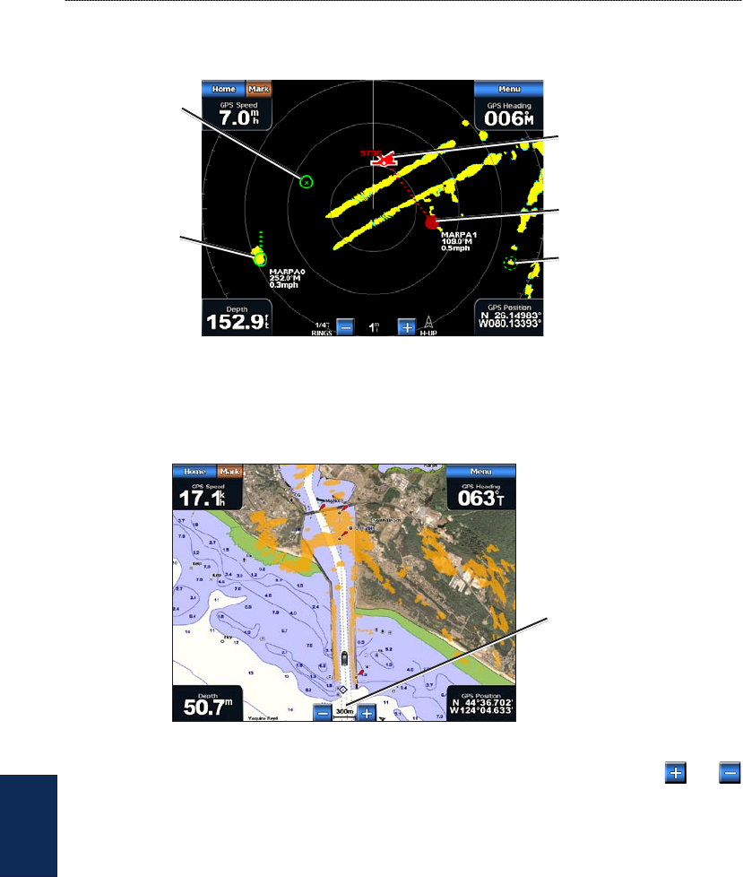
42 GPSMAP
®
4000/5000 Series Owner’s Manual
Using Radar
Using
Radar
MARPA Target (only appears when you are targeting a tagged MARPA object)—opens the
MARPA target information window.
MARPA Targeting
Acquiring
MARPA target
Tracking
MARPA target
Lost MARPA
target
Dangerous
MARPA target
Closest point and time of
approach to dangerous
MARPA target
Understanding the Radar Overlay Screen
Use the Radar Overlay option to overlay radar information on the Navigation chart.
Radar range
From the Home screen select Radar > Radar Overlay. The radar picture appears in orange and
overlays the Navigation chart. Use the RANGE (+/-) keys (GPSMAP 4000 series) or the and
keys (GPSMAP 5000 series) to zoom in and out. Zooming while panning the map only affects the
zoom scale of the map. The radar range remains the same. Zooming while the map is locked on the
boat (not panning) affects the zoom scale of the map and the radar range.
To access additional settings or options for the radar overlay screen, select Menu. Select Setup >
Chart Setup to access the chart options. Select Radar Setup to return to the radar setup options.
Obtaining Optimal Radar Display Performance
The gain controls the sensitivity of the radar receiver. The default setting for the gain, Auto, adjusts
the gain automatically to provide the best performance.
To adjust the gain:
1. Select Menu > Gain on the radar screen.
2. Select Up or Down to manually adjust the gain; select Auto to return the gain to the default
setting.

GPSMAP
®
4000/5000 Series Owner’s Manual 43
Using Radar
Using
Radar
Reducing Unwanted Noise
There are several options that adjust the gain to help reduce unwanted clutter on the radar screen.
To reduce unwanted noise:
1. From the Radar screen, select Menu > Noise Rejection.
2. Select from the following options:
Rain Cltr—adjust the gain for unwanted clutter caused by rain at close ranges. Select Up or
Down to adjust the rain clutter sensitivity.
Sea Cltr—adjust the gain for clutter caused by choppy sea conditions. Select Rough,
Medium, or Calm. Select Up or Down to manually adjust the sea clutter sensitivity.
Cross Talk—lter out interference caused by another radar operating in close proximity.
FTC (Fast Time Constant)—reduce unwanted clutter caused by rain at a distance. FTC has
four presets: Off, Low, Medium, or High.
Adjusting the VRM and EBL
The Variable Range Marker (VRM) and Electronic Bearing Line (EBL) tools measure range and
bearing to a target. You can adjust the diameter of the VRM and the angle of the EBL.
To show or hide the VRM and EBL:
The measured range and bearing are displayed in the upper-left corner of the screen.
If the VRM and EBL are hidden, from the Radar screen, select Menu > Show VRM/EBL.
If the VRM and EBL are shown, from the Radar screen, select Menu > Adjust VRM/EBL >
Hide VRM/EBL.
To select the VRM/EBL target location:
(GPSMAP 4000 series) On the Radar screen, use the ROCKER to move the pointer to the
VRM/EBL target location and select Drop VRM/EBL.
(GPSMAP 5000 series) On the Radar screen, touch the target location and select Drop
VRM/EBL.
To adjust the VRM/EBL target location:
1. From the Radar screen, select Menu > Adjust VRM/EBL > Move VRM/EBL.
2. Use the ROCKER to move the pointer (GPSMAP 4000 series) or touch the target location
(GPSMAP 5000 series).
3. Press DONE to accept the changes.
Conguring Other Vessels on the Radar Screen
You can congure which other vessels are displayed on the radar screen, from the Radar screen,
select Menu > Other Vessels.
NOTE: To congure AIS or DSC information for other boats, your unit must be connected to an
external AIS or DSC device.
List—display a list of AIS and MARPA threats. Select Show to select between displaying AIS or
MARPA threats, or All Threats.
DSC—turn DSC (Digital Selective Calling) trails on or off, congure how many hours a trail for a
DSC vessel is displayed on the Radar screen, or display a list of tracked DSC vessels.
Collision Alarm (AIS and MARPA only)—turn a safe zone around your boat on or off. This is used
for collision avoidance, and can be customized.
•
•
•
•
•
•
•
•

44 GPSMAP
®
4000/5000 Series Owner’s Manual
Using Radar
Using
Radar
To customize safe-zone settings:
1. From the Radar screen, select Menu > Other Vessels > Collision Alarm.
2. Select from the following options:
Range—change the measured radius of the safe zone ring to a specied distance from 500 ft.
to 2.0 nm (or from 150 m to 3.0 km, or from 500 ft. to 2.0 mi).
Time to (Safe Zone)—sounds an alarm if AIS or MARPA determines that a target will intersect
the Safe Zone within the dened time interval (ranging from 1 to 24 minutes).
Display Setup—congure how other vessels are displayed on the Radar screen.
Display Range—set the distance from your location that AIS vessels are displayed.
Details—show or hide details for each vessel.
Proj. Heading—set the projected heading time.
Trails—set the number of minutes that trails for vessels that you are position tracking (page 51)
are displayed on the Radar screen, or turn trails off.
Advanced Radar Conguration
To access advanced radar settings, from the Radar screen, select Menu > Radar Setup.
Rotation Speed (GMR 18/24/404/406 series models only)—set the rotation speed of your radar to
Normal Speed or High Speed. High Speed increases the speed at which the antenna rotates, which
increases the speed at which the screen updates.
Front of Boat—offset the front of the boat if you mount the radar at an angle.
Data Bars—show or hide cruising, navigation, shing, fuel, or sailing numbers (page 9).
Appearance—congure radar display options.
Color Scheme—change the colors used for the radar display.
Orientation—change the perspective of the radar display.
Look-Ahd Spd—turn on to shift your current location toward the bottom of the screen as your
speed increases. Enter your top speed for the best results.
Heading Line—show or hide a line in the direction of travel.
Rings—show or hide the radar range rings.
Nav Lines—show or hide a colored line that indicates the route you are currently navigating.
Waypoints—show or hide waypoints that are within the range displayed on the Radar screen.
Select Navigation Only to only display waypoints associated with the currently active route.
•
•
•
•
•
•
•
•
•
•
•
•
•
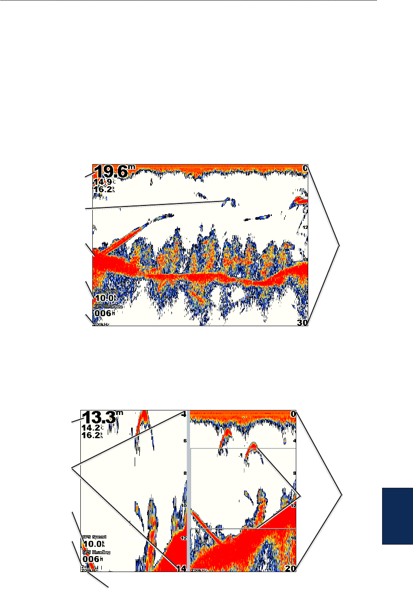
GPSMAP
®
4000/5000 Series Owner’s Manual 45
Using Sonar
Using
Sonar
Using Sonar
When connected to an optional Garmin GSD 22 sounder module and a transducer, your chartplotter
can be used as a shnder. The GSD 22 connects through the Garmin Marine Network and shares
sonar data with every chartplotter connected to the network.
Understanding the Full Screen
Select the Full Screen option to view a full-screen graph of the sonar readings from the transducer.
The range scale along the right side of the screen shows the depth of detected objects as the screen
scrolls from the right to the left.
From the Home screen, select Sonar > Full Screen.
Suspended
target
Bottom
Depth, temperature,
and water speed
GPS speed and
GPS heading
Transducer
frequency
Range
Understanding the Split Zoom Screen
Use the Split Zoom screen to view the full sonar data from the graph and a zoomed-in portion on the
same screen.
From the Home screen, select Sonar > Split Zoom.
Range
Depth, temperature,
and water speed
GPS speed and
GPS heading
Transducer frequency
Zoom level
Zoom
window
Zoomed depth
scale
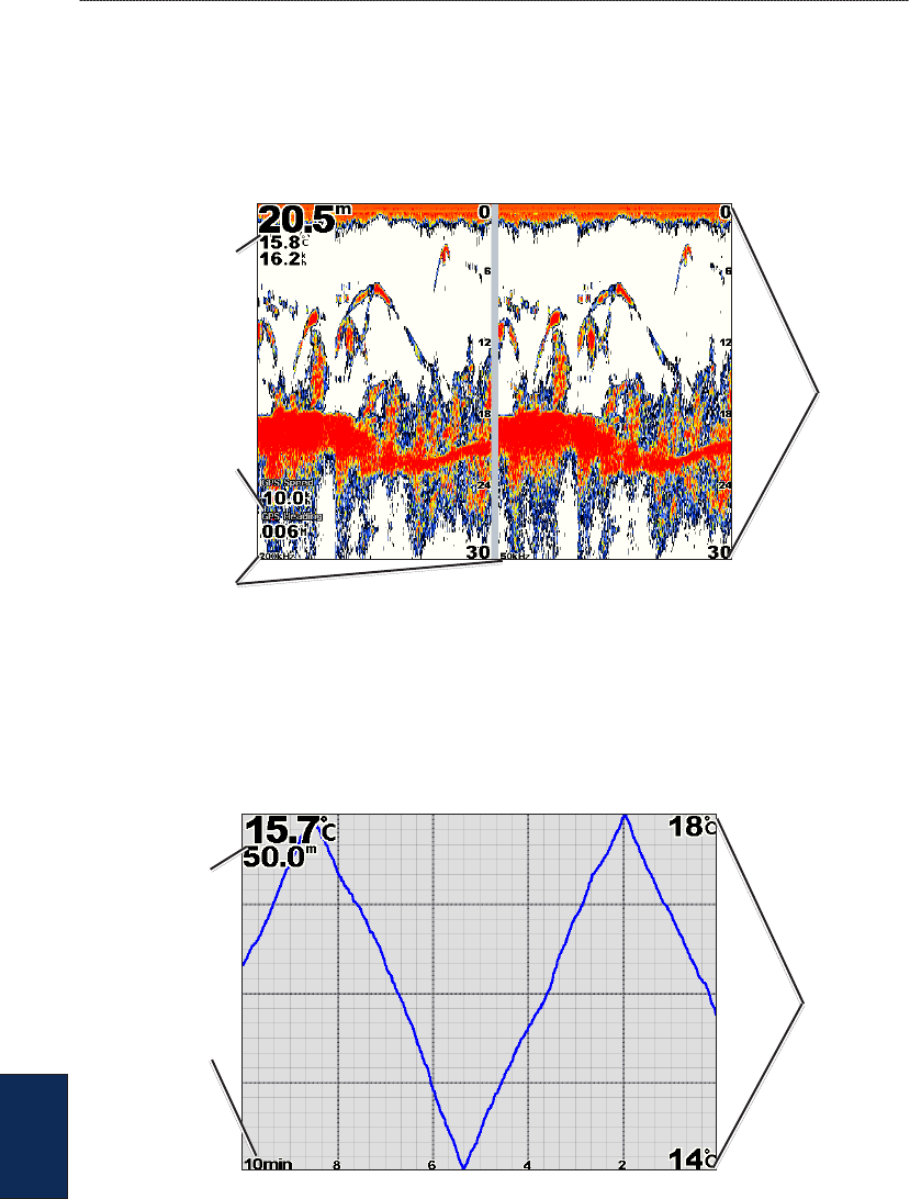
46 GPSMAP
®
4000/5000 Series Owner’s Manual
Using Sonar
Using
Sonar
Understanding the Split Frequency Screen
Use the Split Frequency screen (dual-frequency transducer only) to view both the 50 kHz and 200
kHz frequencies on the same screen. A 200 kHz frequency graph appears on the left; a 50 kHz
frequency graph appears on the right.
From the Home screen, select Sonar > Split Frequency.
Depth, temperature,
and water speed
GPS speed and
GPS heading
Transducer
frequencies
Range
Understanding the Temp Log
If you are using a temperature-capable transducer, the Temp Log screen keeps a graphic log of
temperature readings over time. The current temperature and depth are shown in the upper-left
corner.
From the Home screen, select Sonar > Temp Log.
Temperature
and depth
Time
elapsed
Temperature
Range
The temperature appears along the right side and the time elapsed appears along the bottom. The
graph scrolls to the left as information is received.
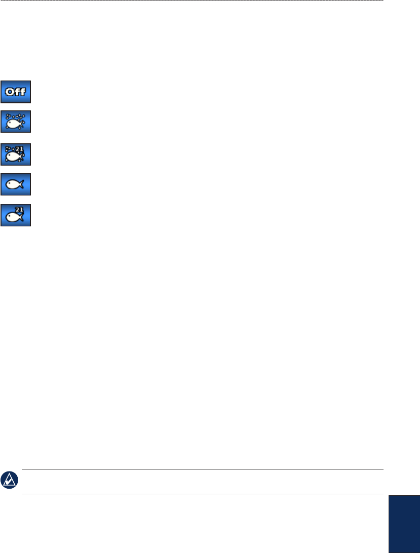
GPSMAP
®
4000/5000 Series Owner’s Manual 47
Using Sonar
Using
Sonar
Setting Up Sonar
Use the Sonar Setup screen to dene and adjust settings universal to all sonar screens.
From the Home screen, select Sonar > Sonar Setup.
Fish Symbols—set how the sonar interprets suspended targets.
The unit does not interpret the sonar return data (default).
Suspended targets appear as symbols. Background sonar information appears, making the
distinction between sh and structure easier.
Suspended targets appear as symbols with background information shown. The target
depth of each symbol is also indicated.
Suspended targets appear as symbols. No background information appears.
Suspended targets appear as symbols with no background information shown. The target
depth of each symbol is indicated.
Scroll Speed—adjust the rate at which the sonar scrolls from right to left (Ultrascroll
™
, Fast,
Medium, or Slow). If using a speed-capable transducer, select Auto to have the scroll speed
automatically adjust to the water speed of your boat.
Whiteline—highlights the strongest signal from the bottom to help identify its hardness or softness.
Off (default)—Whiteline is disabled.
High—the most sensitive setting. Almost all strong returns are highlighted in white.
Medium—many strong returns are highlighted in white.
Low—the least sensitive setting. Only the strongest returns are highlighted in white.
Color Scheme—select White or Blue. This affects the background on all sonar screens, but does
not change the Temp Log screen.
Surface Noise—show or hide the sonar returns near the surface of the water. Hide surface noise to
help reduce clutter.
Overlay Numbers—show or hide water temperature, battery voltage, water speed (if your
transducer is capable), and navigation numbers.
NOTE: To show water temperature or water speed, change the setting to Auto. If the connected
transducer is capable, the data is shown.
A-Scope—creates a vertical asher along the right side of the screen (On or Off).
•
•
•
•

48 GPSMAP
®
4000/5000 Series Owner’s Manual
Using Sonar
Using
Sonar
Advanced Sonar Settings
To adjust advanced sonar settings, select Menu while viewing a sonar screen.
Gain—controls the sensitivity of the sonar receiver (Auto or, to adjust manually, Up or Down). To
see more detail, increase the gain. If the screen is cluttered, decrease the gain.
Sonar Scroll—select to stop scrolling. Select Create Waypoint to save the location as a waypoint,
and select Resume to continue scrolling in real time. For more information on waypoints, see
page 23.
Frequency—selects how the frequencies appear on screen (200kHz, 50kHz, or Dual).
Zoom—zoom in to a section of the Full Screen. The zoom is off, or set to No Zoom, by default.
Four options are available:
2x Zoom—twice the magnication. Select Up, Down, or Auto to set the depth range of the
magnied area.
4x Zoom—four times the magnication. Select Up, Down, or Auto to set the depth range of the
magnied area.
Bottom Lock—locks the zoom window to the bottom. Select Up, Down, or Auto to set the
depth range of the magnied area.
No Zoom—turns zooming off.
Depth Line—quickly reference a specic depth (Show or Hide). When Show is selected, press
up or down on the ROCKER (GPSMAP 4000 series) or touch and drag the line (GPSMAP 5000
series) to set the depth of the reference line.
Range—the range of the depth scale on the right side of the screen (Auto, or to adjust manually, Up
or Down).
Sonar Setup—opens the Sonar Setup screen. See page 47.
•
•
•
•
GPSMAP
®
4000/5000 Series Owner’s Manual 49
Digital Selective Calling
DSC
Digital Selective Calling (DSC)
Using the Chartplotter with a VHF Radio
The following table indicates the features that are available when you connect your chartplotter to a
VHF radio over a NMEA 0183 network or a NMEA 2000 network.
Feature NMEA 0183
VHF Radio
NMEA 2000
VHF Radio
Garmin NMEA
0183 VHF Radio
Garmin NMEA
2000 VHF Radio
The chartplotter can transfer your GPS
position to your radio. If your radio is
capable, GPS position information is
transmitted with DSC calls.
X X X X
The chartplotter can receive DSC
distress and position information from
the radio (page 50).
X X X X
The chartplotter can track the positions
of vessels sending position reports
(page 51).
X X X X
Quickly set up and send individual
routine call details to your Garmin VHF
radio (page 50).
X
When you initiate a man-overboard
distress call from your radio, the
chartplotter displays the man-overboard
screen and prompts you to navigate to
the man-overboard point (page 50).
X
When you initiate a man-overboard
distress call from your chartplotter, the
radio displays the Distress Call page to
initiate a man-overboard distress call
(page 50).
X
To turn DSC on or off:
1. Select Congure > Other Vessels.
2. Select DSC to turn it on or off.
If you are using radar, see page 43 for information on conguring how DSC information displays on
the radar screen.
Adding a DSC Contact
You can make calls to a DSC contact from the chartplotter. See page 52 for information on making
an individual routine call.
To add a DSC contact:
1. While viewing a chart, select Menu > Other Vessels > DSC List > Add Contact.
2. Use the ROCKER (GPSMAP 4000 series) or onscreen keyboard (GPSMAP 5000 series) to enter
the MMSI number of the vessel and select Done.
3. Use the ROCKER or the onscreen keyboard to enter the name of the vessel and select Done.
The contact is now available in the DSC List.
50 GPSMAP
®
4000/5000 Series Owner’s Manual
Digital Selective Calling
DSC
Viewing the DSC List
The DSC List is a log of the most-recent DSC calls and other DSC contacts you have entered. The
DSC List can contain up to 100 entries. The DSC List shows the most-recent call from a boat. If a
second call is received from the same boat, it replaces the rst call in the Call List. To view the DSC
List, from a chart screen, select Menu > Other Vessels > DSC List.
Receiving Distress Calls
If your Garmin chartplotter and VHF radio are connected via NMEA 0183 or NMEA 2000, your
chartplotter alerts you when your VHF radio receives a DSC distress call. If position information
was sent with the distress call, that information is also available and recorded with the call.
The symbol designates a distress call in the DSC List and marks the position of a vessel on the
Navigation Chart at the time a DSC distress call is sent.
When you receive a DSC distress call:
1. Select Review to view details about the call.
2. Select from one of the following options:
Call with Radio—although the radio will automatically switch to monitor Channel 16 when
it receives a distress call, you can use this option to set up an individual routine call with the
radio to call the vessel in distress (page 52). This option is only available if you are using a
Garmin NMEA 2000-compatible VHF radio.
Edit—edit the vessel name and add a comment. If your radio is tracking the position of the
vessel, select Trail to show or hide the trail line for the vessel, and select Trail Line to change
the line color.
Clear Report—delete the call report.
Navigate To—Go To or Route To the position sent with the distress call (page 21).
The symbol marks the position of the vessel on the Navigation Chart at the time a DSC
distress call is sent.
Create Waypoint—set a waypoint at the position sent with the distress call.
Next Page/Previous Page—toggle between details related to the distress call and a
Navigation Chart marking the position sent with the distress call.
Man-Overboard Distress Calls Initiated from a VHF Radio
When your Garmin chartplotter is connected to a Garmin NMEA 2000-compatible radio and you
initiate a man-overboard DSC distress call from your radio, your Garmin chartplotter displays
the man-overboard screen and prompts you to navigate to the man-overboard point. If you have
a Garmin autopilot system connected to the network, your chartplotter prompts you to start a
Williamson’s turn to the man-overboard point.
If you cancel the man-overboard distress call on the radio, the chartplotter screen prompting you to
activate navigation to the man-overboard location is no longer displayed.
Man-Overboard Distress Calls Initiated from the Chartplotter
When your Garmin chartplotter is connected to a Garmin NMEA 2000-compatible radio and you
activate navigation to a man-overboard location, the radio displays the Distress Call page to initiate
a man-overboard distress call. On the radio, press and hold the DISTRESS key for at least three
seconds to send the distress call.
For information on placing distress calls from your radio, see your Garmin VHF Radio Owner’s
Manual. For information on activating navigation to a man-overboard location, see page 23.
•
•
•
•
•
•
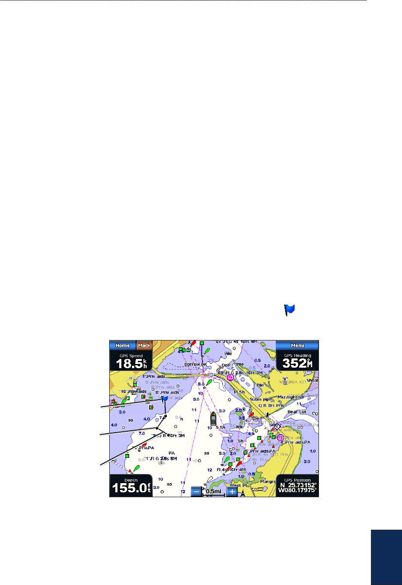
GPSMAP
®
4000/5000 Series Owner’s Manual 51
Digital Selective Calling
DSC
Position Tracking
When you connect your Garmin chartplotter to a VHF radio using NMEA 0183, you can track
vessels that send position reports. This feature is also available with NMEA 2000, provided that the
vessel sends the correct PGN data (PGN 129808; DSC Call Information).
Every position report call received is logged in the DSC List (page 50).
To view a list of position reports:
1. From the Home screen, select Information > DSC List.
2. Select from the following options:
Call with Radio—set up an individual routine call (page 52) with the radio to call the vessel
that sent the position report. This option is only available if you are using a Garmin NMEA
2000-compatible VHF radio.
Edit—edit the vessel name and add a comment. If your radio is tracking the position of the
vessel, select Trail to show or hide the trail line for the vessel, and select Trail Line to change
the line color.
Clear Report—delete the call report.
Navigate To—Go To or Route To the location sent with the position report (page 21).
Create Waypoint—set a waypoint at the location sent with the position report.
Next Page/Previous Page—toggle between details of the position report and a Navigation
Chart marking the location.
Conguring Vessel Trails on the Navigation Chart
If you have your chartplotter congured to show trails, the Navigation Chart displays a black dot
for each reported position, a black line indicating the path of the vessel, and a Blue Flag symbol
indicating the last reported position.
Vessel trail
Last-reported
vessel position
Position-report
location
Vessel Trail
To set the duration of displayed trail points:
1. From a chart screen, select Menu > Other Vessels > DSC > DSC Trails.
2. Select the number of hours to show tracked vessels on the Navigation Chart. For example, if you
select 4 Hours, all trail points (less than four hours old) for tracked vessels are displayed.
To turn trail lines off for tracked vessels:
1. From a chart screen, select Menu > Other Vessels > DSC > DSC Trails.
2. Select Off to turn trails off for every vessel.
•
•
•
•
•
•
52 GPSMAP
®
4000/5000 Series Owner’s Manual
Digital Selective Calling
DSC
To show or hide the trail line for a specic vessel that is sending position reports:
1. From the Home screen, select Information > DSC List.
2. Select the vessel from the list, and then select Review.
3. Select Trail to show or hide the trail for the vessel on the Navigation Chart.
To change the symbol and color of the trail line for a vessel:
1. From the Home screen, select Information > DSC List.
2. Select any call from that vessel from the list, and then select Review > Edit.
3. Select Symbol to edit the symbol, or select Trail Line to edit the line color.
Placing an Individual Routine Call
When you connect your Garmin chartplotter to a Garmin VHF NMEA 2000-compatible radio, you
can use the chartplotter interface to set up an individual routine call. When setting up an individual
routine call from your chartplotter, you can select one of the following channels on which you want
to communicate. The radio transmits this request with your call.
The selection of a DSC channel is limited to those channels that are available in all frequency bands:
6, 8, 9, 10, 13, 15, 16, 17, 67, 68, 69, 71, 72, 73, or 77.
NOTE: The default channel is 72. However, select Channel to select a different channel from the list.
If you select a different channel, the chartplotter will use that channel for subsequent calls until you call
using a different channel.
To make an individual routine call:
1. While viewing a chart, select Menu > Other Vessels > DSC List.
2. Select the station to call from the list.
3. Select Review > Call with Radio.
4. Select Send to send the information about the call to the radio.
5. On your Garmin VHF radio, select Call.
Calling an AIS Target
When you connect your Garmin chartplotter to a Garmin VHF NMEA 2000-compatible radio, you
can use the chartplotter interface to set up an individual routine call to an Automatic Identication
System (AIS) target. For more information on selecting a channel other than the default channel
(Channel 72), see “Placing an Individual Routine Call.”
To make an individual routine call to an AIS target:
1. While viewing a chart, select an AIS target .
2. Select AIS Vessel > Call with Radio.
3. Select Send to send the information about the call to the radio.
4. On your Garmin VHF radio, select Call.

GPSMAP
®
4000/5000 Series Owner’s Manual 53
Appendix
Appendix
Appendix
Specications
Physical Specications
Size: GPSMAP 4008: 7" H × 11.2" W × 4.2" D (176.9 × 284.4 × 106 mm)
GPSMAP 4010: 8.9" H × 13.4" W × 4.13" D (226.9 × 340.4 × 105.1 mm)
GPSMAP 4012: 9.47" H × 14.8" W × 4.13" D (240.5 × 375 × 105.1 mm)
GPSMAP 5008: 6.8" H × 10.1" W × 4.17" D (173.5 × 256 × 105.9 mm)
GPSMAP 5012: 9.47" H × 13" W × 4.7" D (240.5 × 330 × 119.2 mm)
GPSMAP 5015: 11.65" H × 15.55" W × 5.66" D (295.8 × 394.9 × 143.8 mm)
Weight: GPSMAP 4008: 6 lb. (2.7 kg)
GPSMAP 4010: 8 lb. (3.5 kg)
GPSMAP 4012: 10 lb. (4.5 kg)
GPSMAP 5008: 6 lb. (2.7 kg)
GPSMAP 5012: 9 lb. (4.3 kg)
GPSMAP 5015: 12 lb. (5.4 kg)
Display: GPSMAP 4008: 5.17" H × 6.85" W (131.4 × 174 mm)
GPSMAP 4010: 6.35" H × 8.43" W (161.4 × 214.2 mm)
GPSMAP 4012: 7.26" H × 9.68" W (184.3 × 245.8 mm)
GPSMAP 5008: 5" H × 6.73" W (128.2 × 170.9 mm)
GPSMAP 5012: 7.11" H × 9.3" W (180.49 × 235.97 mm)
GPSMAP 5015: 8.98" H × 11.97" W (228.1 × 304.1 mm)
Case: Fully Gasketed, high-impact plastic and aluminum alloy, waterproof to IEC 529-IPX
Temp. Range: from 5° to 131°F (from -15° to 55°C)
Compass Safe Distance: GPSMAP 4008/5008: 2.6 ft. (80 cm)
GPSMAP 4012/5012: 3.3 ft. (1 m)
GPSMAP 4010: 3.3 ft. (1 m)
GPSMAP 5015: 1.3 ft. (40 cm)
Hg - LAMPS INSIDE THIS PRODUCT CONTAIN MERCURY AND MUST BE RECYCLED OR
DISPOSED OF ACCORDING TO LOCAL, STATE, OR FEDERAL LAWS.
For more information go to:
www.garmin.com/aboutGarmin/environment/disposal.jsp.
GPS Performance (with GPS 17 antenna)
Receiver: Differential-ready 12 parallel channel WAAS-capable receiver
Acquisition Times:
Warm: 15 seconds
Cold: 45 seconds
AutoLocate: 2 minutes
Update Rate: 1/second, continuous
GPS Accuracy:
Position: <15 m (49 ft), 95% typical
Velocity: 0.05 meters/second steady state
54 GPSMAP
®
4000/5000 Series Owner’s Manual
Appendix
Appendix
WAAS Accuracy:
Position: <3 m (9.8 ft), 95% typical
Velocity: 0.05 meters/second steady state
Dynamics: 6 g
Power
Source: 10–35 Vdc
Usage: GPSMAP 4008/5008: 35 W max. at 10 Vdc
GPSMAP 4010/4012/5012: 40 W max at 10 Vdc
GPSMAP 5015: 60 W max at 10 Vdc
Fuse: 7.5 A, 42 V fast-acting
NMEA 2000 Specications
Load Equivalency Number (LEN): 2
Unit Draw: 75 mA max
Calibrating the Touchscreen
For GPSMAP 5008/5012/5015 units, you might have to calibrate the touchscreen.
CAUTION: Do not calibrate the touchscreen unless you are certain that it is necessary.
To calibrate the touchscreen on GPSMAP 5000 series units:
1. Turn on the unit. When the Warning screen appears, touch and hold the black screen for at least
15 seconds until the calibration screen appears.
2. Follow the on-screen directions to calibrate the touchscreen.
Capturing Screenshots
You can capture a screenshot of any screen displayed on your unit as a bitmap (.BMP) le and then
transfer it to your computer.
NOTE: To capture screenshots on the GPSMAP 5000 series, you need the optional Garmin RF Wireless
Remote Control.
To capture screenshots:
1. Insert an SD card into the SD card slot on the front of the unit.
2. Select Congure > System > Beeper/Display.
3. Select Screenshot Capture to turn screenshot captures On.
4. When you are on a screen you want to capture:
(GPSMAP 4000 series) Press the HOME button on the unit for at least six seconds.
(GPSMAP 5000 series) Press the HOME button on the Garmin RF Wireless Remote Control
for at least six seconds.
5. Select OK when the Screenshot Taken window is displayed.
To copy the screenshots to your computer:
1. Remove the SD card from the chartplotter and insert it into an SD card reader that is attached to
a computer.
2. From Windows Explorer, open the Garmin\scrn folder on the SD card.
3. Copy the appropriate .BMP le on the card and paste it to any location on the computer.
•
•

GPSMAP
®
4000/5000 Series Owner’s Manual 55
Appendix
Appendix
Alarms and Messages
Accuracy Alarm (GPS)—the GPS accuracy has fallen
outside the user-set value.
AIS: Dangerous Target—an AIS target presents a
collision threat.
Alarm Clock—the alarm clock has sounded.
Anchor Drag Alarm—the boat has drifted out of the user-
set distance range.
Antenna Input is Shorted —there is a short in the wiring
to the GPS 17 antenna.
Approaching Waypoint <name>—the boat is a specied
alarm distance from the destination waypoint.
Arrival Alarm <name>—arriving at destination waypoint.
Auto-guidance unable to calculate route—(BlueChart g2
Vision) auto-guidance cannot calculate the route.
Auto-guidance unable to calculate route, please shorten
route—(BlueChart g2 Vision) auto-guidance cannot
calculate the route, select a closer end point.
Auto-guidance unable to calculate route. Starting
position not within safe depth—(BlueChart g2 Vision)
auto-guidance cannot calculate the route; boat is not in a
safe depth.
Auto-guidance unable to calculate route. Ending
position not within safe depth—(BlueChart g2 Vision)
auto-guidance cannot calculate the route; select an end
point within the specied safe depth
Battery Alarm—Battery voltage is at or below the user-set
value.
Boat is not Moving Fast Enough to Calibrate—(speed
sensor) appears during water-speed calibration. Check
speed wheel for blockage and calibrate again. If wheel is
clear, calibrate again and increase speed.
Can’t Read User Card—cannot read card when
attempting a user data transfer.
Can’t Read Voltages That High, Limited To Top Of
Range—entering a battery-alarm voltage higher than the
unit can read.
Can’t Read Voltages That Low, Limited To Bottom Of
Range—entering a battery-alarm voltage lower than the
unit can read.
Can’t Unlock Maps—maps are locked and cannot be used
on this unit.
Can’t Write User Card—cannot write card when
attempting a user data transfer.
Cartography Service Incompatible. Software Update
Required—a software update is needed. Contact Garmin
Product Support for assistance updating your unit software.
Cooling Fan Voltage Too High—the cooling-fan voltage
is higher than expected. Contact product support.
Cooling Fan Voltage Too Low—the cooling-fan voltage is
lower than expected. Contact product support.
Database Error—general database error. Contact Garmin
Product Support.
Deep Water Alarm—(sonar) the boat has entered user-
dened value for deep water.
Directory Item With This MMSI Already Exists—the
MMSI unit is already in directory.
Directory Memory is Full Can’t Create Entry—DSC
directory is full, no more entries can be created.
Distress Call Received From <name>—A distress call
has been received by the DSC module.
Drift Alarm—the boat has moved a user-dened distance.
DSC Position Report Received From <name>—a
position report has been received by the DSC module.
Entering Target Water Temperature—(temperature
sensor/transducer) the water temperature is inside the user-
dened target temperature zone.
GPS Antenna Has Lost Its Stored Settings—The GPS
antenna memory has been cleared. Contact Garmin Product
Support.
GPS Service Incompatible. Software Update
Required—a GPS service software update is needed.
Contact Garmin Product Support for assistance updating
your unit software.
GPS Service Lost—the unit has lost communications with
the remote GPS unit. Check the network and the antenna
wiring.
Incompatible Device, Software Update Required—an
incompatible device is attached that requires a software
update. Contact Garmin Product Support for assistance
updating your network.
Invalid Device Instance. Enter a number between
(0 - 252)—invalid NMEA 2000 Device instance.
Invalid Entry. Default value selected.—an invalid entry
was entered.
Invalid MMSI—an invalid DSC MMSI was entered.
Invalid System Instance. Enter a number between
(0 - 15)—invalid NMEA 2000 System instance.
Leaving Target Water Temperature—(temperature
sensor/transducer) the water temperature is outside the
user-dened target temperature zone
Low Fuel Alarm—(NMEA 2000) low fuel reported by the
NMEA 2000 network.
Lost Heading Sensor Connection— (radar/NMEA) the
unit has lost communications with the heading sensor.
Check wiring.
Lost Remote GPS Connection—connection to the remote
GPS has been lost. Check the network and the antenna
wiring.
Lost Satellite Reception—the unit has lost satellite
reception. Make sure you have a clear view of the sky.
Map Format Is Not Supported—a map format on a
preprogrammed SD card is not supported.
MARPA: Dangerous Target—(radar) a MARPA target
has become dangerous.

56 GPSMAP
®
4000/5000 Series Owner’s Manual
Appendix
Appendix
MARPA: Target Lost—(radar) unable to track a MARPA
target any longer.
NMEA Depth Is Below Transducer—(sonar) the NMEA
depth input is using the DBT sentence which does not
include keel offset.
No DGPS Position—the unit lost differential GPS
reception (WAAS). Make sure you have a clear view of
the sky.
No Proximity Waypoints Found—no proximity
waypoints found while attempting a user data transfer.
No Routes Found—no routes found while attempting a
user data transfer.
No Tracks Found—no tracks found while attempting a
user data transfer.
No User Waypoints Found—no user waypoints found
while attempting a user data transfer.
Not All Maps Fit, Some Maps Will Not Be Drawn—
there are more maps present on the SD card than the unit
can support. Some maps on the card will not be drawn or
used to nd map features.
Off Course Alarm—the boat has left the user-dened
course.
Proximity Alarm—the boat has come close to a user-
dened proximity point.
Proximity Alarm Memory is Full—the proximity
waypoint memory is full. Erase existing proximity
waypoints to make room.
Proximity Overlaps Another Proximity Waypoint—a
proximity point is overlapping another proximity waypoint.
Radar Guard Zone Alarm—(radar) an object has been
detected in the user-dened radar guard zone.
Radar Needs Repair Error Code—(radar) the radar needs
repair. An error code will be listed to help diagnose the
error.
Radar Service Incompatible. Software Update
Required—a radar software update is needed. Contact
Garmin Product Support for assistance updating your
network.
Radar Service Lost—(radar) the unit has lost
communications with the remote radar unit. Check the
network and the radar wiring.
Route Already Exists—the named route already exists.
Select another name.
Route is Full—the individual route is full, no more
waypoints can be added.
Route Memory is Full, Can’t Create Route—the
chartplotter route memory is full, no more routes can be
created. Erase existing routes to make room.
Route Truncated—some points on the end of the route
have been discarded.
Shallow Water Alarm—(sonar) the boat has entered the
user-dened shallow-water depth.
Simulating Operation—the unit is in Simulator Mode.
Sonar Failed, Unit Needs Repair—there has been a sonar
failure and the unit needs to be sent in for repair. Contact
Garmin Product Support.
Sonar Service Incompatible. Software Update
Required—a software update is needed. Contact Garmin
Product Support for assistance updating your network.
Sonar Service Lost—(sonar) the unit has lost
communications with the remote sonar unit. Check the
network and the sonar wiring.
Tide Alarm—the tide has reached the user-specied tide
alarm range.
Track Already Exists—the named track already exists.
Select another name.
Track Log Full—there is no longer any space in the active
track log storage.
Track Truncated—some points on the end of the track
have been discarded.
Transducer Disconnected, Sonar Turned Off—the
transducer has been disconnected. Sonar has been turned
off. Check transducer wiring.
Transfer Complete—user data transfer is complete.
Unknown bridge height within calculated auto-guidance
route—(BlueChart g2 Vision) there is an unknown bridge
height within the auto-guidance route.
User Card Not Found—user data card transfer. Make sure
an SD card is fully inserted.
Water Speed Sensor not Working—the water speed
sensor is not working properly. Check the wheel for
obstructions and check wiring.
Water Temperature Alarm—(temperature sensor/
transducer) the water temperature has entered or left the
user-dened water temperature alarm zone.
Warning: Auto-guidance route starting position moved
due to safe depth settings—(BlueChart g2 Vision) auto-
guidance has calculated the route, but the starting point has
been moved to deeper water.
Warning: Auto-guidance route ending position moved
due to safe depth settings—(BlueChart g2 Vision) auto-
guidance has calculated the route, but the end point has
been moved to deeper water.
Waypoint Already Exists—the named waypoint already
exists. Select another name.
Waypoint Memory is Full, Can’t Create Waypoint—the
User Waypoint memory is full. Erase existing waypoints to
make room.

GPSMAP
®
4000/5000 Series Owner’s Manual 57
Appendix
Appendix
Product Registration
Help us better support you by completing our online registration today! Connect to our Web site at
http://my.garmin.com. Keep the original sales receipt, or a photocopy, in a safe place.
Contact Garmin
Contact Garmin Product Support if you have any questions while using your GPSMAP 4000 series
or GPSMAP 5000 series chartplotter. In the USA, go to www.garmin.com/support, or contact
Garmin USA by phone at (913) 397.8200 or (800) 800.1020.
In the UK, contact Garmin (Europe) Ltd. by phone at 0808 2380000.
In Europe, go to www.garmin.com/support and click Contact Support for in-country support
information, or contact Garmin (Europe) Ltd. by phone at +44 (0) 870.8501241.
Declaration of Conformity (DoC)
Hereby, Garmin, declares that this unit is in compliance with the essential requirements and other
relevant provisions of Directive 1999/5/EC.
To view the full Declaration of Conformity, see the Garmin Web site for your Garmin product:
www.garmin.com.
Software License Agreement
BY USING THE UNIT, YOU AGREE TO BE BOUND BY THE TERMS AND CONDITIONS OF THE FOLLOWING
SOFTWARE LICENSE AGREEMENT. PLEASE READ THIS AGREEMENT CAREFULLY.
Garmin grants you a limited license to use the software embedded in this device (the “Software”) in binary executable
form in the normal operation of the product. Title, ownership rights, and intellectual property rights in and to the Software
remain in Garmin.
You acknowledge that the Software is the property of Garmin and is protected under the United States of America
copyright laws and international copyright treaties. You further acknowledge that the structure, organization, and code of
the Software are valuable trade secrets of Garmin and that the Software in source code form remains a valuable trade secret
of Garmin. You agree not to decompile, disassemble, modify, reverse assemble, reverse engineer, or reduce to human
readable form the Software or any part thereof or create any derivative works based on the Software. You agree not to
export or re-export the Software to any country in violation of the export control laws of the United States of America.
58 GPSMAP
®
4000/5000 Series Owner’s Manual
Appendix
Appendix
NMEA 0183 and NMEA 2000
The GPSMAP 4000 and GPSMAP 5000 series chartplotters can accept data from NMEA 0183
compliant devices and also from certain NMEA 2000 devices connected to an existing NMEA 2000
network on your boat.
NMEA 0183
The NMEA 0183 data cable included with the GPSMAP 4000 and GPSMAP 5000 series
chartplotters support the NMEA 0183 standard, which is used to wire various NMEA 0183-
compliant devices such as VHF radios, NMEA instruments, autopilots, wind sensors, or heading
sensors.
The GPSMAP 4000 and GPSMAP 5000 series chartplotters can receive data from up to four NMEA
0183-compliant devices and send GPS data to up to six NMEA 0183-compliant devices.
To wire a GPSMAP 4000 or GPSMAP 5000 series chartplotter to optional NMEA 0183-compliant
devices, see the GPSMAP 4000/5000 Series Installation Instructions.
Approved NMEA 0183 Sentences
GPBWC, GPRMC, GPGGA, GPGSA, GPGSV, GPGLL, GPBOD, GPRMB, GPRTE, GPVTG,
GPWPL, GPXTE, and Garmin proprietary sentences—PGRME, PGRMM, and PGRMZ.
This unit also includes support for the WPL sentence, DSC, and sonar NMEA 0183 input with
support for the DPT (depth) or DBT, MTW (water temp), and VHW (water temp, speed, and
heading) sentences.
NOTE: To congure how the unit manages these NMEA 0183 sentences, see page 33.
NMEA 2000
The GPSMAP 4000 and GPSMAP 5000 series chartplotters are NMEA 2000 certied and can
receive data from a NMEA 2000 network installed on the boat.
To connect a GPSMAP 4000 or GPSMAP 5000 series chartplotter to an existing NMEA 2000
network and to see a list of supported NMEA 2000 PGN numbers, see the GPSMAP 4000/5000
Series Installation Instructions.
All GPSMAP 4000 and GPSMAP 5000 series chartplotters are NMEA 2000
certied.

GPSMAP
®
4000/5000 Series Owner’s Manual 59
Index
Index
A
A-scope 48
additional object information 8
aerial photos 18
AIS 36
alarms 34, 55
navigation 34
safe zone 36, 44
sonar 35
system 34
anchor drag 34
automatic guidance 18, 35
autopilot capabilities 49
B
backing up data 29
backlight
adjusting 3
sensor 1
backlight sensor 1
beeper 32
BlueChart g2 Vision 14, 37
bottom lock 48
bridging 34
C
calibrate water speed 36
celestial information 28
chart appearance 10
chart data 7
chartplotter capabilities 49
charts 5, 6
additional object information 8
appearance 10
borders 11
detail 10
sh eye 3D 6
shing 6
mariner’s eye 6
navigation 6
panning 7
settings 9
using 6
zooming 6
clear user data 30
colors 15
color mode 3
color scheme 47
combinations 19–20
communications settings 33
congure 5, 32–36
my boat 35
other boats 36
water speed 36
contact Garmin 57
course up 10
create waypoint 8
creating routes 25
cruising screen (radar) 40
current information 27
current station 18, 27
D
data
clear user data 30
transfer 29, 37
user 28
Data Bars 9, 12, 16
declaration of conformity 57
delete all 30
delete a waypoint 24, 30
depth line 48
detail 10
device list 34
DSC 30, 36, 43, 49
E
EBL 43
edit a route 26
edit existing waypoint 24
engine gauges 30
F
factory settings
restoring 4
sh eye 3D 6, 16
settings 16
shing charts 16
sh symbols 47
frequency 48
FTC 43
fuel gauges 31
full screen 45
G
gain 48
gauges
engine 30
fuel 31
GMR 18 37, 39
GMR 21/41 37
GMR 404/406 37, 39
go to 21
GPS satellite signals 3, 32
GSD 22 37
guide to 21
H
Hazard Colors 15
heading 33
Heading Line 10
heading line 11
cruising screen 44
Head Up 10
high-resolution satellite imagery 17
home screen i, 5
I
information 5, 8
DSC 30
information screen 27
initializing the unit 53
inset map 7, 10
K
keel offset 36
L
lane width 12
light sectors 11
look-ahd spd 44
M
man overboard 23
map datum 33
MapSource data 28
marine network 37
mariner’s eye 6
mariner’s eye 3D 14
colors 15
mark current location 23
mark key 1
MARPA 42
Measure Distance 8
menu key 1
messages 55
move a waypoint 24
my boat 35
N
Navaid Type 10
navigate to 8, 21
navigation chart 6
nearby stations 27
network 37–38
viewing connected devices 38
New Waypoint 11
NMEA 0183 33, 58
NMEA 2000 34, 54, 58
north up 10
numeric keypad 1
O
object information 8
orientation 44
other boats 30, 36
overlay numbers 47

60 GPSMAP
®
4000/5000 Series Owner’s Manual
Index
P
panning the navigation chart 7
Perspective 3D 11
photos 9, 17, 18
POI data 18
position format 33
position icon 7
POWER key 1
preferred devices 34
product registration 57
R
radar 39–44
cross talk 43
fast time constant 43
overlay screen 42
surface 12
range 48
Range keys 1
Range Rings 12
registration 57
restoring factory settings 4
review 8
rings 9, 44
roads 18
Rocker 1
Roses 9
routes
creating 25
deleting 26
deleting all 30
editing 26
route to 21
S
Safe Depth 12
safe depth 35
safe height 35
safe zone 36
satellite signals 3
scroll speed 47
SD cards
inserting and removing 4
search for a destination by name 22
Service Points 9
settings
alarms 34
chart 9
combinations 20
communications 33
sh eye 3D 16
initializing 2
mariner’s eye 3D 15
navigation chart 6
sonar 47
sonar (advanced) 48
system 32
simulator mode 4, 32
soft keys i, 1
sonar 45–48
a-scope 48
color scheme 47
depth line 48
sh symbols 47
frequency 48
full screen 45
gain 48
range 48
scroll speed 47
split frequency screen 46
split zoom screen 45
surface noise 47
temp log 46
whiteline 47
zoom 48
sonar cone 16
specications 53
split frequency screen 46
split zoom screen 45
spot depths 10
stop navigating 22
sun and moon 28
surface noise 47
Surface Radar 12
symbols 10
system information
viewing 4
system settings 32
T
targeting (radar) 41
temp log 46
Tides/Currents 9
tide station 8, 27
tracks 12, 16
deleting all 30
transfer data 29, 37
turn the unit off 2
U
unit ID number
viewing 4
units of measure 32
user data 28
V
video 31
view
system information 4
VRM 43
VRM/EBL
adjusting 43
W
waypoints 11, 23
create new 23
deleting 23, 24
edit existing 11, 24
man overboard 23
mark current location 23
moving 24
Waypoints & Tracks 6
where to 5, 21–26
whiteline 47
wireless devices 34
Z
zoom 6, 48

For the latest free software updates (excluding map data) throughout the life of your
Garmin products, visit the Garmin Web site at www.garmin.com.
© 2009 Garmin Ltd. or its subsidiaries
Garmin International, Inc.
1200 East 151st Street, Olathe, Kansas 66062, USA
Garmin (Europe) Ltd.
Liberty House, Hounsdown Business Park, Southampton, Hampshire, SO40 9LR UK
Garmin Corporation
No. 68, Jangshu 2nd Road, Shijr, Taipei County, Taiwan
www.garmin.com
April 2009 Part Number 190-01077-00 Rev. B Printed in Taiwan
