Garmin Ghc 20 Control Unit Technical Reference Guide
2015-05-27
: Garmin Garmin-Ghc-20-Control-Unit-Technical-Reference-Guide-721013 garmin-ghc-20-control-unit-technical-reference-guide-721013 garmin pdf
Open the PDF directly: View PDF ![]() .
.
Page Count: 42
- Introduction
- NMEA 2000 Fundamentals
- General NMEA 2000 Data Type Requirements
- NMEA 2000-Certified Display Device PGN Information
- NMEA 2000-Certified Sensor PGN Information
- GPS 17x (GPS Antenna)
- GFS 10 (Garmin Fuel Sensor)
- GRA 10 (Garmin Rudder Angle Adapter)
- GET 10 (Garmin Engine Tilt Adapter)
- GFL 10 (Garmin Fluid Level Adapter)
- GBT 10 (Garmin Bennett Trim Tab Adapter)
- GST 10 (Garmin Water Speed and Temperature Adapter)
- Intelliducer (Intelligent Depth Transducer–Transom Mount and Thru-Hull)
- GWS 10 (Garmin Wind Sensor)
- GHP 10 (Marine Autopilot System)
- GXM 51
- VHF 200
- VHF 300
- AIS 300
- AIS 600
- NMEA 2000-Certified Sensor Configuration Information
- GPS 17x (GPS Antenna)
- GFS 10 (Garmin Fuel Sensor)
- GRA 10 (Garmin Rudder Angle Adapter)
- GET 10 (Garmin Engine Tilt Adapter)
- GFL 10 (Garmin Fluid Level Adapter)
- Restoring Factory Default Settings
- GBT 10 (Garmin Bennett Trim Tab Adapter)
- GST 10 (Garmin Water Speed and Temperature Adapter)
- Restoring Factory Default Settings
- Intelliducer (Intelligent Depth Transducer–Transom Mount and Thru-Hull)
- GWS 10 (Garmin Wind Sensor)
- NMEA 2000 Checklist
+-
Technical Reference
for Garmin®
NMEA 2000® Products
All rights reserved. Except as expressly provided herein, no part of this manual may be reproduced, copied, transmitted, disseminated, downloaded or stored in any storage
medium, for any purpose without the express prior written consent of Garmin. Garmin hereby grants permission to download a single copy of this manual onto a hard drive or
other electronic storage medium to be viewed and to print one copy of this manual or of any revision hereto, provided that such electronic or printed copy of this manual must
contain the complete text of this copyright notice and provided further that any unauthorized commercial distribution of this manual or any revision hereto is strictly prohibited.
Information in this document is subject to change without notice. Garmin reserves the right to change or improve its products and to make changes in the content without
obligation to notify any person or organization of such changes or improvements. Visit the Garmin Web site (www.garmin.com) for current updates and supplemental
information concerning the use and operation of this and other Garmin products.
Garmin
®
, the Garmin logo, and GPSMAP
®
are trademarks of Garmin Ltd. or its subsidiaries, registered in the USA and other countries. GFS™, GWS™, GHP™, GXM™,
GFL™, GBT™, GST™, GMI™, GRA™, GET™, GHC™, Intelliducer™, are trademarks of Garmin Ltd. or its subsidiaries. These trademarks may not be used without the
express permission of Garmin.
NMEA 2000
®
and the NMEA 2000 logo are registered trademarks of the National Maritime Electronics Association.

Technical Reference for Garmin NMEA 2000 Products iii
Introduction
Introduction
A NMEA 2000 network consists of connected NMEA 2000 devices that communicate using basic plug-and-play functionality. This technical
reference provides basic NMEA 2000 component identication, basic NMEA 2000 network-building instructions, and a list of NMEA 2000-
specic data used with Garmin NMEA 2000-certied displays and sensors.
• The rst section, NMEA 2000 Fundamentals, provides descriptions of the NMEA 2000 connectors and cables sold by Garmin, and the
fundamental concepts of installing a NMEA 2000 network on your boat.
• The second section, General NMEA 2000 Data Type Requirements, provides a table to help you determine which NMEA 2000 sensors
provide the particular data type you want.
• The last two sections provide Parameter Group Number (PGN) information for Garmin chartplotters and marine instruments as well as
conguration and PGN information for Garmin NMEA 2000 sensors. These sections contain PGN and conguration information for the
following products:
◦ GPSMAP
®
4000/5000/6000/7000 Series chartplotters
◦ GPSMAP 700 Series chartplotters
◦ GPSMAP 4x1/5x1/5x6 Series chartplotters
◦ GMI
™
10
◦ GPS 17x
◦ GFS
™
10
◦ GRA
™
10
◦ GET
™
10
◦ GFL
™
10
◦ GBT
™
10
◦ GST
™
10
◦ Intelliducers
™
◦ GWS
™
10
◦ GHP
™
10 (CCU and GHC
™
10)
◦ GXM
™
51
◦ VHF 200/300
◦ AIS 300
◦ AIS 600
PGN information is also included in the installation instructions provided with the Garmin NMEA 2000-certied device. Sensor conguration
information is also included in a Sensor Conguration Guide provided with each Garmin NMEA 2000-certied sensor.
• At the end is a checklist. Use this checklist when installing a NMEA 2000 network to be sure you have correctly followed installation-
critical procedures.
Contact Garmin
If you experience difculty installing a NMEA 2000 network, or have other questions about NMEA 2000-certied Garmin devices, contact
Garmin Product Support or a certied NMEA 2000 technician. In the USA, go to www.garmin.com/support, or contact Garmin USA by phone
at (913) 397-8200 or (800) 800-1020.
In the UK, contact Garmin (Europe) Ltd. by phone at 0808 2380000.
In Europe, go to www.garmin.com/support and click for in-country support information, or contact Garmin (Europe) Ltd. by
phone at +44 (0) 870.8501241.

iv Technical Reference for Garmin NMEA 2000 Products
Table of Contents
Table of Contents
Introduction ....................................................................................................................................................................................... iii
Contact Garmin ......................................................................................................................................................................................................iii
NMEA 2000 Fundamentals ................................................................................................................................................................ 1
Garmin NMEA 2000 Device Overview ................................................................................................................................................................... 1
Building a NMEA 2000 Network ............................................................................................................................................................................. 3
Existing NMEA 2000 Installation Considerations ................................................................................................................................................... 8
NMEA 2000 Glossary ............................................................................................................................................................................................. 8
General NMEA 2000 Data Type Requirements ................................................................................................................................ 9
NMEA 2000-Certied Display Device PGN Information ............................................................................................................... 13
NMEA 2000-Certied Sensor PGN Information ............................................................................................................................ 18
GPS 17x (GPS Antenna) ..................................................................................................................................................................................... 18
GFS 10 (Garmin Fuel Sensor) ............................................................................................................................................................................. 18
GRA 10 (Garmin Rudder Angle Adapter) ............................................................................................................................................................. 18
GET 10 (Garmin Engine Tilt Adapter) .................................................................................................................................................................. 18
GFL 10 (Garmin Fluid Level Adapter) .................................................................................................................................................................. 19
GBT 10 (Garmin Bennett Trim Tab Adapter) ........................................................................................................................................................ 19
GST 10 (Garmin Water Speed and Temperature Adapter) .................................................................................................................................. 19
Intelliducer (Intelligent Depth Transducer–Transom Mount and Thru-Hull) ......................................................................................................... 19
GWS 10 (Garmin Wind Sensor) ........................................................................................................................................................................... 20
GHP 10 (Marine Autopilot System) ...................................................................................................................................................................... 20
GXM 51 ................................................................................................................................................................................................................ 21
VHF 200 ............................................................................................................................................................................................................... 21
VHF 300 ............................................................................................................................................................................................................... 21
AIS 300 ................................................................................................................................................................................................................ 22
AIS 600 ................................................................................................................................................................................................................ 22
NMEA 2000-Certied Sensor Conguration Information ............................................................................................................. 23
GPS 17x (GPS Antenna) ..................................................................................................................................................................................... 23
GFS 10 (Garmin Fuel Sensor) ............................................................................................................................................................................. 24
GRA 10 (Garmin Rudder Angle Adapter) ............................................................................................................................................................. 26
GET 10 (Garmin Engine Tilt Adapter) .................................................................................................................................................................. 27
GFL 10 (Garmin Fluid Level Adapter) .................................................................................................................................................................. 29
Restoring Factory Default Settings ...................................................................................................................................................................... 32
GBT 10 (Garmin Bennett Trim Tab Adapter) ........................................................................................................................................................ 32
GST 10 (Garmin Water Speed and Temperature Adapter) .................................................................................................................................. 33
Restoring Factory Default Settings ...................................................................................................................................................................... 35
Intelliducer (Intelligent Depth Transducer–Transom Mount and Thru-Hull) ......................................................................................................... 36
GWS 10 (Garmin Wind Sensor) ........................................................................................................................................................................... 36
NMEA 2000 Checklist ......................................................................................................................................................................................... 37
Technical Reference for Garmin NMEA 2000 Products 1
NMEA 2000 Fundamentals
NMEA 2000 Fundamentals
A NMEA 2000 network is made of connected NMEA 2000 devices that communicate using basic plug-and-play functionality.
If your boat already contains a NMEA 2000 network and you would like to add Garmin NMEA 2000 components, see page 8.
For a glossary of commonly used NMEA 2000 terms, see page 8.
After you have installed your NMEA 2000 network, use the checklist on page 37 to verify the installation.
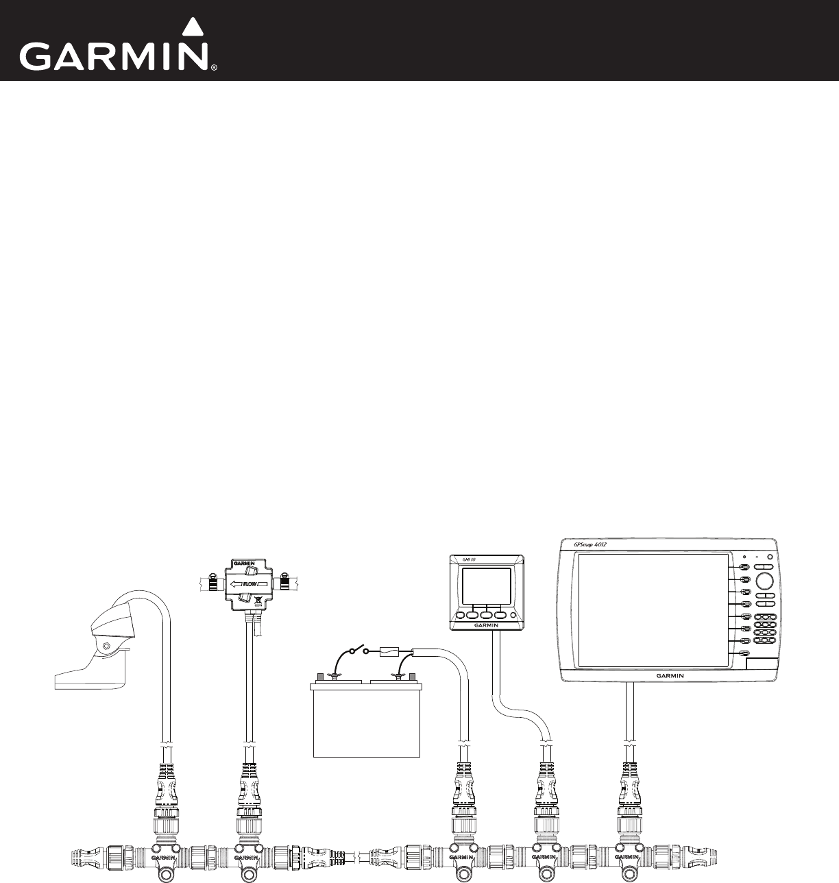
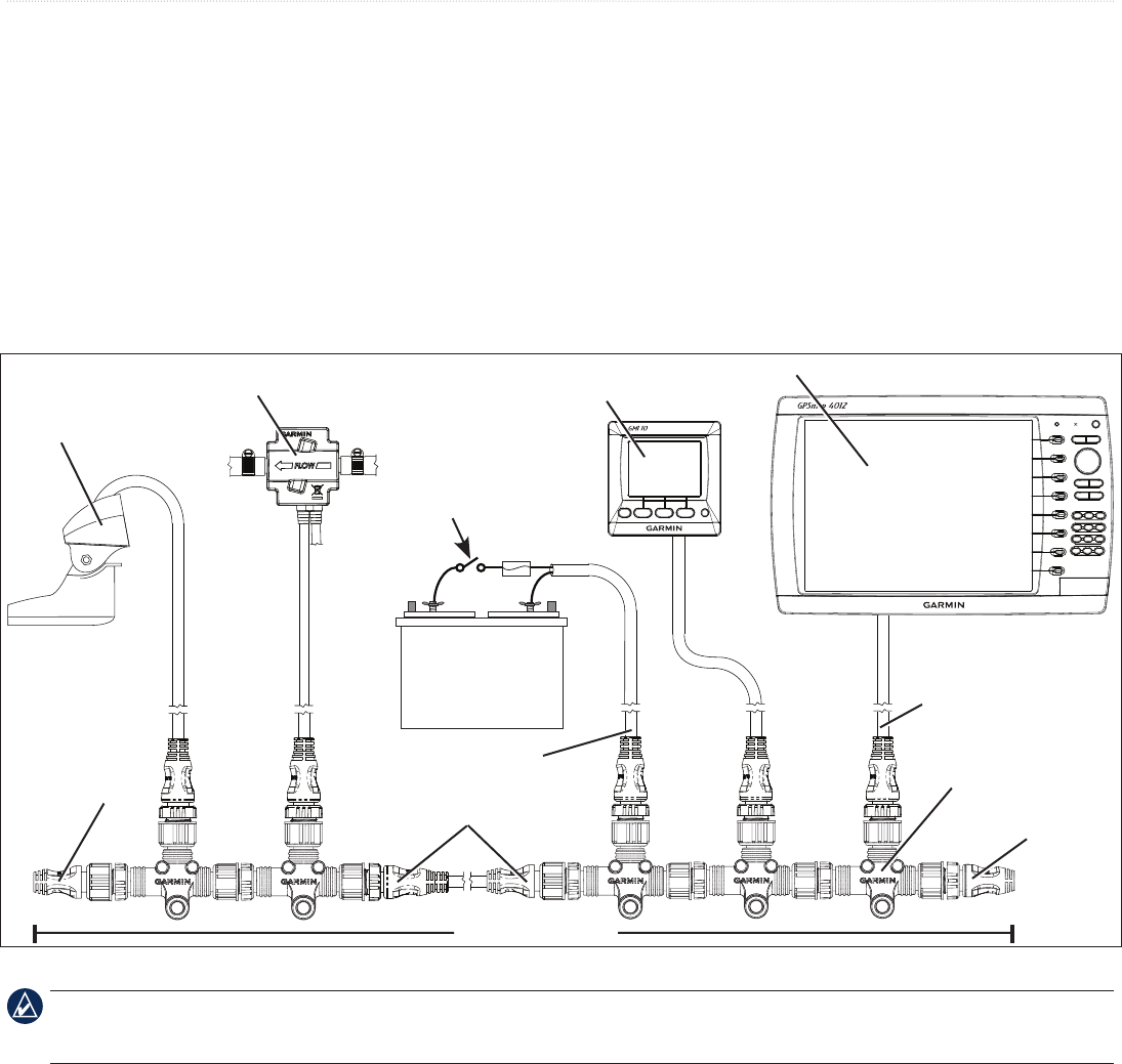
Garmin NMEA 2000 Device Overview
Garmin uses NMEA 2000 micro connectors on units, sensors, and T-connectors that are compatible with other NMEA 2000 micro connectors,
cables, and NMEA 2000-compatible devices. Garmin sensors may be packaged with a drop cable and a T-connector. Garmin displays may also
include additional NMEA 2000 components (such as a power cable). The NMEA 2000 components included with a Garmin sensor or display
are listed in the product documentation. A diagram on the product box shows which NMEA 2000 components are included.
+-
Sample Box Diagram (GFS 10)
In the sample box diagram, a complete NMEA 2000 network is shown, and the parts included with the sensor are shaded. In this example, a
T-connector is included with a Garmin GFS 10 fuel sensor. A NMEA 2000 power cable, terminators, an additional drop/backbone cable, and
additional T-connectors are not included with a GFS 10 fuel sensor. The GFS 10 fuel sensor, as shown by the shaded components in the box
diagram, is intended to be connected to an existing NMEA 2000 network on your boat. If you do not have a NMEA 2000 network on your boat,
this guide will help you assemble one.
2 Technical Reference for Garmin NMEA 2000 Products
NMEA 2000 Fundamentals
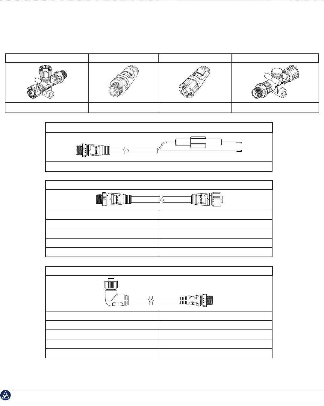
NMEA 2000 Components
The main components of a NMEA 2000 network are T-connectors, terminators, backbone/drop cables, and a power cable. The following cables,
connectors, and terminators are sold by Garmin, and as of January 2009, they are NMEA 2000 approved. NMEA 2000-approved cables sold by
Garmin feature the NMEA 2000 logo on the tag with the part number.
T-connector Male Terminator Female Terminator In-line Terminator
010-11078-00 (Garmin part number) 010-11080-00 010-11081-00 010-11096-00
Power Cable
010-11079-00 (2 meters [6.5 feet]) (3 A fuse included)
Backbone/Drop Cable
305 millimeters (1 foot) 010-11076-03
2 meters (6.5 feet) 010-11076-00
6 meters (20 feet) 010-11076-01
10 meters (33 feet) (backbone only) 010-11076-02
30 meter spool (98.5 feet) (backbone only) 010-11171-01
Specialty Cable/Connectors
Right-angle drop-cable, 2 meters (6.5 feet) (pictured) 010-11089-00
Field-installable connector - Male* (not pictured) 010-11094-00
Field-installable connector - Female* (not pictured) 010-11095-00
NMEA 2000 network power switch (not pictured) K00-00368-00
NMEA 2000 in-line lightning arrestor** (not pictured) 010-11171-02
* The eld-installable connectors are used to create custom-length drop cables and custom-length backbone extension cables. The eld-installable connectors can be used to
shorten any Garmin NMEA 2000 drop/backbone cable.
** The gray in-line lightning arrestor is designed to help prevent damage due to nearby lightning strikes, but it is not able to protect against direct lightning strikes. Garmin is
not responsible for lightning-strike related damage.
All male/female connections are interchangeable. Ensure that the T-connectors are used properly when constructing your NMEA 2000 network.
See page 4.
Technical Reference for Garmin NMEA 2000 Products 3
NMEA 2000 Fundamentals
Building a NMEA 2000 Network
The main communication channel of a NMEA 2000 network is a backbone to which your NMEA 2000 devices connect. Each NMEA 2000
device connects to the backbone with a T-connector. The NMEA 2000 backbone must be connected to power, and terminators must be installed
at both ends for the network to function correctly.
When you design a NMEA 2000 network, start by creating a diagram of the network. When creating the diagram, be as detailed as possible:
• Include all of the devices you intend to connect to your network
• Note the approximate location of the backbone and devices on your boat
• Measure the distances between devices and the backbone, as well as the overall length of the backbone
• Note the power consumption of each device (Load Equivalency Number)
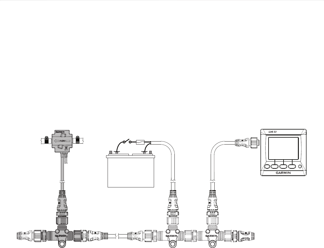
Sample NMEA 2000 Network
+-
Ignition or
in-line switch
T-connector
Male
terminator
Power cable
Battery - 12 Vdc
Backbone extension cable
Female
terminator
Drop cable
Intelligent transducer
Fuel sensor Marine instrument
Chartplotter
NMEA 2000 backbone
Fuse
This diagram illustrates the NMEA 2000 data connections to each device or sensor. Some devices or sensors can be powered by the NMEA
2000 network; others may require a separate power connection. Consult the installation instructions for each device you connect to your NMEA 2000
network to be sure you supply power to the device appropriately.
When building a NMEA 2000 network, you must follow certain rules to make sure your NMEA 2000 network functions correctly. Be sure to
understand the following concepts:
• Linear backbone construction (page 4)
• Power connection and distribution (page 5)
• Proper termination (page 7)
• Cable length and device limits (page 8)
4 Technical Reference for Garmin NMEA 2000 Products
NMEA 2000 Fundamentals
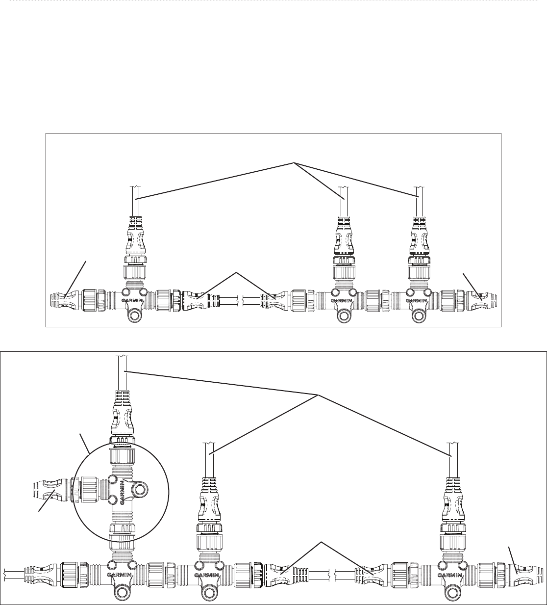
Linear Backbone Construction
Use the NMEA 2000 T-connectors to construct your NMEA 2000 backbone, and extend the backbone with appropriate lengths of backbone
cable if necessary. Use one T-connector per device. Use the sides of the T-connector to construct the backbone of the NMEA 2000 network, and
use the top of the T-connector to attach a NMEA 2000 device. By using only the sides of the T-connectors to construct the backbone, you create
a linear construction to your NMEA 2000 network. T-connectors can be separated by backbone cables or connected directly together.
Although the male and female connectors on the T-connectors and backbone cables will t on all sides of a T-connector, it is very important to
use the top of the T-connector only to attach NMEA 2000 devices, not to attach other T-connectors or backbone cables.
Correct Linear Backbone Construction
CORRECT
To NMEA 2000 devices
and power
Male
terminator
Female
terminator
Backbone extension cable
Incorrect Linear Backbone Construction
INCORRECT
To NMEA 2000 devices
and power
Male
terminator
(also installed
incorrectly)
Male
terminator
T-connector
installed incorrectly
Backbone extension cable
Technical Reference for Garmin NMEA 2000 Products 5
NMEA 2000 Fundamentals
Power Connection and Distribution
Your NMEA 2000 network must be connected to a 12 Vdc power supply. Do not connect your NMEA 2000 network to any other voltage
source, such as a 24 Vdc power supply. Use a NMEA 2000 power cable to connect your NMEA 2000 backbone to the auxiliary power switch
on your boat. If you do not have an auxiliary power switch, or if connecting to the auxiliary power switch causes electrical interference, connect
the NMEA 2000 power cable directly to the battery and install an in-line switch.
If you connect the NMEA 2000 network to your battery without an in-line switch, it may drain your battery.
Be sure to ground the NMEA 2000 power cable. Connect the bare shield-drain wire to the same location as the ground (black) wire.
The Garmin NMEA 2000 power cable connects to a T-connector like other drop cables. Be sure to connect the NMEA 2000 power cable to the
top of a T-connector; never connect the NMEA 2000 power cable to the side of a T-connector. You can connect power either at the end of your
NMEA 2000 network or in the middle. When planning where to place the power cable and the T-connector on your NMEA 2000 network, you
will need to evaluate how the NMEA 2000 devices connected to your network use power. The NMEA 2000 network will work properly when
there is no more than a 3 Vdc drop in the supply voltage between the power source and the NMEA 2000 device located farthest from the power
source on the NMEA 2000 network. To determine the voltage drop in your NMEA 2000 network, use this equation:
Voltage Drop = Cable resistance (ohms/m)* × Distance (from the battery to the farthest device, in meters) × Network Load** × 0.1
* Garmin cable resistance value = 0.053
** Network Load = the sum of Load Equivalent Numbers (LEN) between the battery and the end of the network. The LEN for each device should be visible on
the device, or provided in the documentation for the device.
• If you calculate a voltage drop of 3.0 Vdc or less, then you can connect power to either the end or the middle of your NMEA 2000 network,
and it will function correctly.
• If you calculate a voltage drop of more than 3.0 Vdc, you must connect power to the middle of your NMEA 2000 network. The location will
depend on the network load and distance from the battery. Try to balance the voltage drop equally on both sides of the power connection.
• If a voltage drop of under 3.0 Vdc is not possible on your NMEA 2000 network, contact a professional installer.
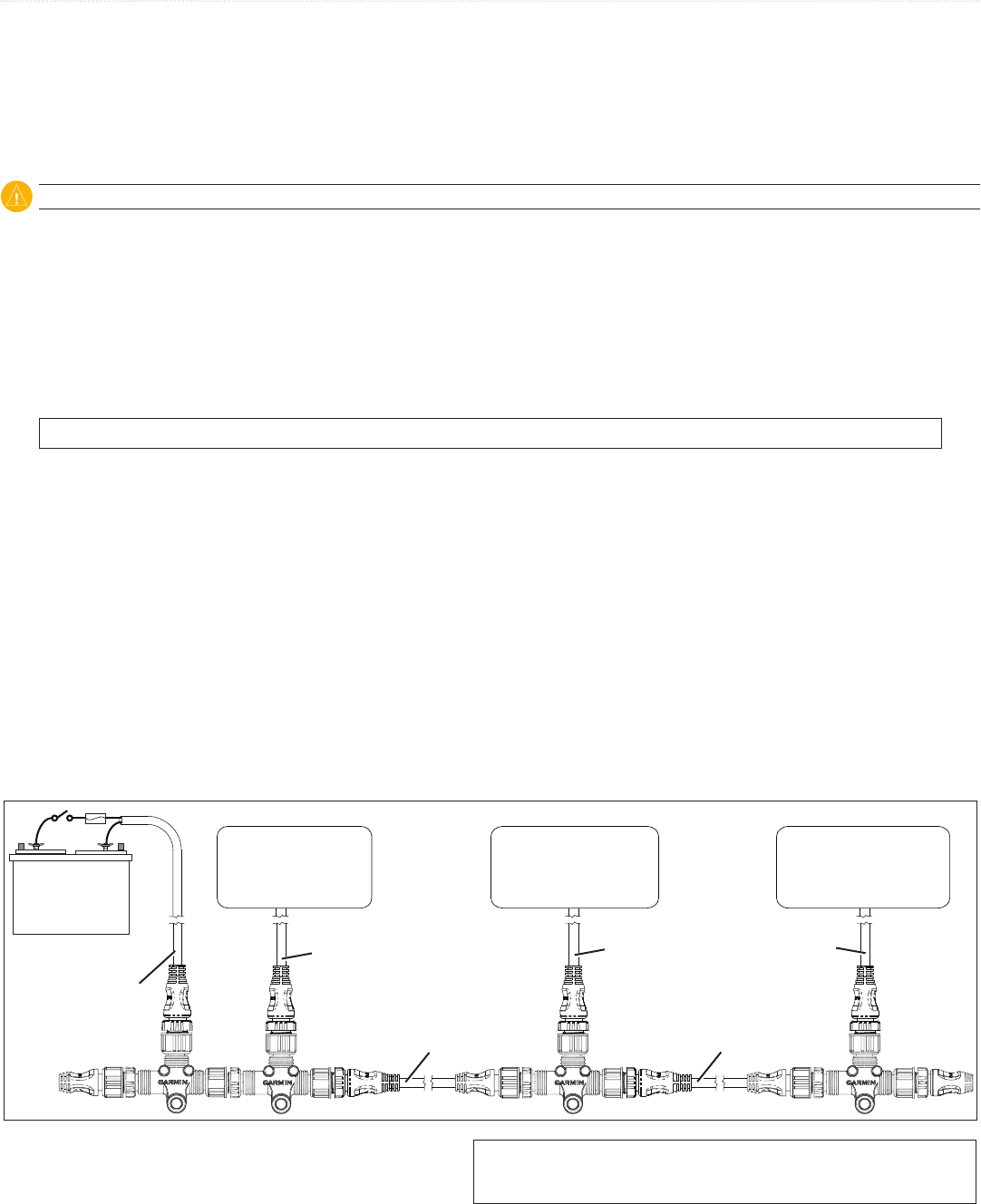
Examples
The following examples show a correctly designed, end-powered NMEA 2000 network; an incorrectly designed NMEA 2000 network; and a
redesign of the incorrectly designed NMEA 2000 network to correctly balance power on the network.
End-powered NMEA 2000 network, correctly designed:
CORRECT
+-
NMEA 2000-
compliant device
LEN = 4
NMEA 2000-
compliant device
LEN = 5
NMEA 2000-
compliant device
LEN = 7
Power cable
Length = 2 m
Drop cable
Length = 2 m
Drop cable
Length = 6 m
Backbone cable
Length = 10 m
Backbone cable
Length = 10 m
Drop cable
Length = 6 m
When the voltage-drop formula is applied to this example, we
see that the voltage drop is less than 3.0 Vdc. This NMEA 2000
network will function correctly when powered at the end.
Voltage Drop = 0.053 × (2 + 10 + 10 + 6) × (4 + 5 + 7) × 0.1 = 2.37 Vdc
Distance Network load
Cable
resistance
6 Technical Reference for Garmin NMEA 2000 Products
NMEA 2000 Fundamentals
End-powered NMEA 2000 network, incorrectly designed:
INCORRECT
+-
NMEA 2000-
compliant device
LEN = 4
NMEA 2000-
compliant device
LEN = 5
NMEA 2000-
compliant device
LEN = 7
Power cable
Length = 2 m
Drop cable
Length = 2 m
Drop cable
Length = 6 m
Backbone cable
Length = 20 m
Backbone cable
Length = 10 m
Drop cable
Length = 6 m
When the voltage drop formula is applied to this example, we see
that the voltage drop is greater than 3.0 Vdc, so this NMEA 2000
network will not function correctly when powered at the end.
Voltage Drop = 0.053 × (2 + 20 + 10 + 6) × (4 + 5 + 7) × 0.1 = 3.22 Vdc
Distance Network load
Cable
resistance
This NMEA 2000 network must be redesigned with the power connected to the center of the network in order to function correctly.
Middle-powered NMEA 2000 network, correctly designed:
CORRECT
+-
NMEA 2000-
compliant device
LEN = 4
NMEA 2000-
compliant device
LEN = 5
NMEA 2000-
compliant device
LEN = 7
Power cable
Length = 2 m
Drop cable
Length = 2 m
Backbone cable
Length = 10 m
Backbone cable
Length = 20 m
Drop cable
Length = 6 m
Drop cable
Length = 6 m
When the NMEA 2000 network is redesigned with the power source in the center, you calculate the voltage drop in both directions. If the
T-connector to which you connect the power source is connected directly to another T-connector (as shown in this example), use the LEN from
that device as part of the calculation for both directions.
Voltage Drop Left = 0.053 × (2 + 20 + 2) × (4 + 5) × 0.1 = 1.145 Vdc
Voltage Drop Right = 0.053 × (2 + 10 + 6) × (5 + 7) × 0.1 = 1.145 Vdc
Distance Network load
Cable
resistance
When the voltage drop formula is applied to both the left and right
sides of the power source in this example, we see that the voltage drop
is less than 3.0 Vdc on each side, so the NMEA 2000 network will
function correctly.
The equation and examples provide conservative estimates for calculating voltage drop.
Technical Reference for Garmin NMEA 2000 Products 7
NMEA 2000 Fundamentals
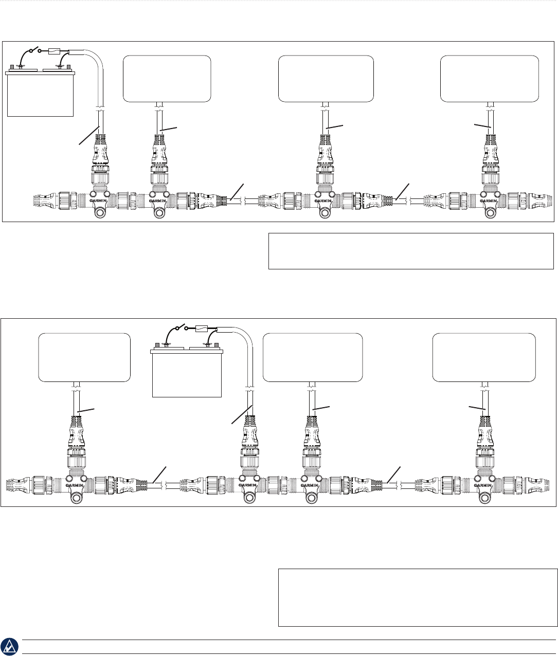
Proper Termination
You must install terminators at the ends of your NMEA 2000 backbone for it to function correctly. You have two options when installing
terminators on your NMEA 2000 network.
1. Typical Terminators
If your NMEA 2000 network is built with correct linear backbone construction, use one female terminator and one male terminator. Install
the terminators at opposite ends of your NMEA 2000 network.
Using Standard Terminators
To NMEA 2000 devices
and power
Male
terminator
Female
terminator Backbone extension cable
2. In-line Terminators
If one or both of the NMEA 2000 devices at opposite ends of your NMEA 2000 network are separated from the rest of the NMEA 2000
network by a length of backbone cable, and the typical T-connector/drop cable/terminator combination is not feasible or is too bulky for the
area, use an in-line terminator instead of the nal T-connector on the backbone. Connect the nal device to the in-line terminator with the
appropriate length of drop cable, or connect the nal device directly to the in-line terminator, without a drop cable.
Using an Inline Terminator
To power
Female
terminator
Backbone
extension
cable Inline
terminator
To a NMEA
2000 device
Inline Termination
Standard Termination
To the nal NMEA 2000 device in the
backbone on this end. Connect the in-line
terminator directly to a NMEA 2000 device,
or use a drop cable up to 6 m (20 ft.) long.
Do not connect additional T-connectors or
terminators.
Do not use more than two terminators in a NMEA 2000 network.
The in-line terminator connects to the NMEA 2000 backbone with a male connector, and to the nal NMEA 2000 device with a female
connector. Because of this, you can only use one in-line terminator on a NMEA 2000 network.

8 Technical Reference for Garmin NMEA 2000 Products
NMEA 2000 Fundamentals
Cable Length and Device Limits
When building your NMEA 2000 network, keep in mind these limitations:
• The distance between any two points on the NMEA 2000 network must not exceed 100 m (328 ft). To estimate this distance, measure
between the terminators on your backbone and add the length of the drop cable for the devices connected to the T-connectors at the ends of
the network.
• The total length of all drop cables cannot exceed 78 m (256 ft).
• The maximum length of a single drop cable to a NMEA 2000 device is 6 m (20 ft).
• No more than 50 NMEA 2000 devices can be connected to your NMEA 2000 network.
Existing NMEA 2000 Installation Considerations
If your boat has an existing NMEA 2000 installation, and you would like to add Garmin NMEA 2000 equipment, there are a few things to
consider:
: Garmin uses NMEA 2000 micro connectors for all cables and connectors. Your existing NMEA 2000 network may use NMEA
2000 mini connectors and cables in the backbone. Mini connectors are larger than micro connectors, and you will need to use a converter or
adapter to connect with Garmin NMEA 2000 devices.
: Is the existing NMEA 2000 network connected to power? A NMEA 2000 network must be connected to power to function correctly
(page 5). Do not connect the NMEA 2000 network to power at more than one location.
: Are terminators installed on the ends of the existing NMEA 2000 backbone? A NMEA 2000 network must be terminated to
function correctly. Do not add more terminators to a NMEA 2000 network if it is already properly terminated.
If you are unsure of any of these considerations, contact your boat manufacturer or a certied NMEA 2000 technician for assistance.
NMEA 2000 Glossary
—Three-way connector with one male and two female micro connectors. A T-connector is used to connect a NMEA 2000 device to
the NMEA 2000 backbone.
—120 ohm resistor located at each end of the NMEA 2000 backbone. Proper termination helps ensure signal integrity across the
entire length of the backbone.
—Special terminator with male and female connectors, which allows direct connection to the a device at the end of the
NMEA 2000 backbone. The inline terminator simplies installation by not requiring a T-connector, terminator, and drop cable for the device at
the end of the backbone.
—Cable connecting a NMEA 2000 device to the NMEA 2000 backbone. Drop cables are limited to 6 m (20 ft.) maximum length.
—In conjunction with T-connectors, the backbone cables create the main communication path of the NMEA 2000 network.
A backbone cable extends the NMEA 2000 backbone to connect NMEA 2000 devices located in different places on the boat. The maximum
backbone cable length is 100 m (328 ft.).
—Electronic hardware that connects to the NMEA 2000 network. A device may only receive data transmitted by other devices on the
network, or may both transmit and receive data on the network.
—12 Vdc power supplied to the NMEA 2000 network. Power should be connected through a switch (instead of directly
connected to the battery) because some devices are always on when NMEA 2000 power is present. NMEA 2000 devices must operate from 9 to
16 Vdc, with a nominal voltage of 12 Vdc.
—A number that indicates the amount of current a device draws from the NMEA 2000 network.
1 LEN = 50 mA. Each device should have an LEN specied on the product or in the product documentation.

Technical Reference for Garmin NMEA 2000 Products 9
General NMEA 2000 Data Type Requirements
General NMEA 2000 Data Type Requirements
Each NMEA 2000-certied sensor provides unique information to the NMEA 2000-certied display devices (such as a GPSMAP 4000/5000
series chartplotter or a GMI 10) on the NMEA 2000 network. The data you can view on your display device depends on the sensors you have
installed and congured. Refer to the following table for a list of data types that you can view on a display device; specic NMEA 2000 PGN
information required to view or calculate that data type; and the NMEA 2000 sensor that typically provides required PGN information. In some
cases, more than one sensor is necessary or a specic combination of sensors may provide more-precise information. For more about PGN
information, see page 18.
Category Data Type PGN Data Required Typical Sender
Engine Information Battery Voltage 127489 - Eng Dynamic NMEA 2000-compatible engine
Fuel Flow Rate 127489 - Eng Dynamic Fuel Flow Sensor
Hours 127489 - Eng Dynamic NMEA 2000-compatible engine
Oil Pressure 127489 - Eng Dynamic NMEA 2000-compatible engine
Engine RPM 127488 - Engine Rapid NMEA 2000-compatible engine
Temperature 127489 - Eng Dynamic NMEA 2000-compatible engine
Coolant Pressure 127489 - Eng Dynamic NMEA 2000-compatible engine
Fuel Pressure 127489 - Eng Dynamic NMEA 2000-compatible engine
Oil Temperature 127489 - Eng Dynamic NMEA 2000-compatible engine
Boost Pressure 127488 - Engine Rapid NMEA 2000-compatible engine
Trim 127488 - Engine Rapid NMEA 2000-compatible engine
Rudder Angle 127245 - Rudder Rudder Angle Sensor
Bow Tabs 130576 - Small Craft Status Trim Tab Sensor
Trim Tabs 130576 - Small Craft Status Trim Tab Sensor
Fuel Information Total Fuel Flow Rate 127489 - Eng Dynamic Fuel Flow Sensor
Total Fuel Onboard 127489 - Eng Dynamic Fuel Flow Sensor
Fuel Economy 127489 - Eng Dynamic (GPS Speed or Water Speed)
Note: The Fuel Economy data type is congurable,
based on the fuel speed source
Fuel Flow Sensor and Speed Sensor
Cruising Range 127489 - Eng Dynamic (GPS Speed or Water Speed) Fuel Flow Sensor and Speed Sensor
Fuel Level 127505 - Fluid Level Fuel Level Sensor
Tank 1 127505 - Fluid Level Fuel Level Sensor
Tank 2 127505 - Fluid Level Fuel Level Sensor
Navigation
Information
Course Made Good 129026 - COG/SOG, 129029 - GNSS Position,
129284 - Nav Data, 129285 - Route, and
129283 - XTE
Garmin Chartplotter and GPS Antenna
Distance Made Good 129026 - COG/SOG, 129029 - GNSS Position,
129284 - Nav Data, and 129285 - Route
Garmin Chartplotter and GPS Antenna
Waypoint Name 129284 - Nav Data or 129285 - Route Garmin Chartplotter
Bearing to Waypoint 129284 - Nav Data Garmin Chartplotter and GPS Antenna
Distance to Waypoint 129284 - Nav Data Garmin Chartplotter and GPS Antenna
Off Course 129283 - XTE Garmin Chartplotter and GPS Antenna
Desired COG 129284 - Nav Data Garmin Chartplotter and GPS Antenna
Heading 127250 - Vessel Heading Heading Sensor
Course Over Ground 129026 - COG/SOG and 129029 - GNSS Position GPS Antenna
(Continued)

10 Technical Reference for Garmin NMEA 2000 Products
General NMEA 2000 Data Type Requirements
Category Data Type PGN Data Required Typical Sender
Navigation
Information
(continued)
GPS Speed 129026 - COG/SOG and 129029 - GNSS Position GPS Antenna
Position 129026 - COG/SOG and 129029 - GNSS Position GPS Antenna
Turn 129026 - COG/SOG, 129029 - GNSS Position, and
129284 - Nav Data
Garmin Chartplotter and GPS Antenna
Trip Odometer 129026 - COG/SOG and 129029 - GNSS Position GPS Antenna
Trip Odometer 129026 - COG/SOG and 129029 - GNSS Position GPS Antenna
Average GPS Speed 129026 - COG/SOG and 129029 - GNSS Position GPS Antenna
Maximum GPS Speed 129026 - COG/SOG and 129029 - GNSS Position GPS Antenna
Water Odometer 128259 - Water Speed Water Speed Sensor
Water Trip Odometer 128259 - Water Speed Water Speed Sensor
Average Water Speed 128259 - Water Speed Water Speed Sensor
Maximum Water Speed 128259 - Water Speed Water Speed Sensor
Weather Barometer 130314 - Actual Pressure, 130310 - Envir Param Old,
or 130311 - Envir Param
Barometric Pressure Sensor
Air Temperature 130312 - Temp, 130310 - Envir Param Old,
or 130311 - Envir Param
Air Temperature Sensor
Humidity 130313 - Humidity or 130311 - Envir Param Humidity Sensor
Wind Speed 130306 - Wind Data, 129026 - COG/SOG, 129029
- GNSS Position, 127250 - Vessel Heading, and
128259 - Water Speed
(If a Heading Sensor and Water Speed Sensor are
not present, a less-accurate reading can be calculated
using only the Wind Sensor and GPS antenna
[130306 - Wind Data, 129026 - COG/SOG and
129029 - GNSS Position])
(If a GPS antenna is not present, a less-accurate
reading can be calculated using only the Wind Sensor,
Water Speed Sensor, and Heading Sensor [130306
- Wind Data, 127250 - Vessel Heading, and 128259 -
Water Speed])
Either:
• Wind Sensor, a Water Speed
Sensor, a Heading Sensor, and a
GPS Antenna
• Wind Sensor and a GPS Antenna
• Wind Sensor, a Water Speed
Sensor, and a Heading Sensor
Wind Direction 130306 - Wind Data, 129026 - COG/SOG, 129029
- GNSS Position, 127250 - Vessel Heading, and
128259 - Water Speed
(If a Heading Sensor and Water Speed Sensor are
not present, a less-accurate reading can be calculated
using only the Wind Sensor and GPS antenna
[130306 - Wind Data, 129026 - COG/SOG and
129029 - GNSS Position])
(If a GPS antenna is not present, a less-accurate
reading can be calculated using only the Wind Sensor,
Water Speed Sensor, and Heading Sensor [130306
- Wind Data, 127250 - Vessel Heading, and 128259 -
Water Speed])
Either:
• Wind Sensor, a Water Speed
Sensor, a Heading Sensor, and a
GPS Antenna
• Wind Sensor and a GPS Antenna
• Wind Sensor, a Water Speed
Sensor, and a Heading Sensor
(Continued)

Technical Reference for Garmin NMEA 2000 Products 11
General NMEA 2000 Data Type Requirements
Category Data Type PGN Data Required Typical Sender
Cardinal Wind Direction 130306 - Wind Data, 129026 - COG/SOG, 129029
- GNSS Position, 127250 - Vessel Heading, and
128259 - Water Speed
(If a Heading Sensor and Water Speed Sensor are
not present, a less-accurate reading can be calculated
using only the Wind Sensor and GPS antenna
[130306 - Wind Data, 129026 - COG/SOG and
129029 - GNSS Position])
(If a GPS antenna is not present, a less-accurate
reading can be calculated using only the Wind Sensor,
Water Speed Sensor, and Heading Sensor [130306
- Wind Data, 127250 - Vessel Heading, and 128259 -
Water Speed])
Either:
• Wind Sensor, a Water Speed
Sensor, a Heading Sensor, and a
GPS Antenna
• Wind Sensor and a GPS Antenna
• Wind Sensor, a Water Speed
Sensor, and a Heading Sensor
Beaufort Scale 130306 - Wind Data, 129026 - COG/SOG, 129029
- GNSS Position, 127250 - Vessel Heading, and
128259 - Water Speed
(If a Heading Sensor and Water Speed Sensor are
not present, a less-accurate reading can be calculated
using only the Wind Sensor and GPS antenna
[130306 - Wind Data, 129026 - COG/SOG and
129029 - GNSS Position])
(If a GPS antenna is not present, a less-accurate
reading can be calculated using only the Wind Sensor,
Water Speed Sensor, and Heading Sensor [130306
- Wind Data, 127250 - Vessel Heading, and 128259 -
Water Speed])
Either:
• Wind Sensor, a Water Speed
Sensor, a Heading Sensor, and a
GPS Antenna
• Wind Sensor and a GPS Antenna
• Wind Sensor, a Water Speed
Sensor, and a Heading Sensor
Sunrise/Sunset 129026 - COG/SOG and 129029 - GNSS Position GPS Antenna
Sailing Apparent Wind Speed 130306 - Wind Data Wind Sensor
Apparent Wind Angle 130306 - Wind Data Wind Sensor
True Wind Speed 130306 - Wind Data and 128259 - Water Speed (If a
Water Speed Sensor is not present, a less-accurate
reading can be calculated using a GPS antenna
instead [129026 - COG/SOG and 129029 - GNSS
Position])
Either a Wind Sensor and Speed Sensor
or a Wind Sensor and a GPS Antenna
True Wind Angle 130306 - Wind Data and 128259 - Water Speed (If a
Water Speed Sensor is not present, a less-accurate
reading can be calculated using a GPS antenna
instead [129026 - COG/SOG and 129029 - GNSS
Position])
Either a Wind Sensor and Speed Sensor
or a Wind Sensor and a GPS Antenna
Wind VMG (Velocity Made Good) 130306 - Wind Data and 128259 - Water Speed (If a
Water Speed Sensor is not present, a less-accurate
reading can be calculated using a GPS antenna
instead [129026 - COG/SOG and 129029 - GNSS
Position])
Either a Wind Sensor and Speed Sensor
or a Wind Sensor and a GPS Antenna
Waypoint VMG 129284 - Nav Data Garmin Chartplotter and GPS Antenna
Maximum Apparent Wind Speed 130306 - Wind Data Wind Sensor
Maximum True Wind Speed 130306 - Wind Data and 128259 - Water Speed (If a
Water Speed Sensor is not present, a less-accurate
reading can be calculated using a GPS antenna
instead [129026 - COG/SOG and 129029 - GNSS
Position])
Either a Wind Sensor, a Heading Sensor,
and Speed Sensor or a Wind Sensor, a
Heading Sensor, and a GPS Antenna
Opposite Tack Heading 130306 - Wind Data, 127250 - Vessel Heading, and
128259 - Water Speed (If a Water Speed Sensor is
not present, a less-accurate reading can be calculated
using a GPS antenna instead [129026 - COG/SOG
and 129029 - GNSS Position])
Either a Wind Sensor, a Heading Sensor,
and Speed Sensor or a Wind Sensor, a
Heading Sensor, and a GPS Antenna
(Continued)

12 Technical Reference for Garmin NMEA 2000 Products
General NMEA 2000 Data Type Requirements
Category Data Type PGN Data Required Typical Sender
Water Depth 128267 - Water Depth Depth Transducer
Temperature 130312 - Temp, 130310 - Envir Param Old, or
130311 - Envir Param
Water Temperature Sensor
Speed 128259 - Water Speed Water Speed Sensor
Set 129026 - COG/SOG, 129029 - GNSS Position,
128259 - Water Speed, and 127250 - Vessel Heading
GPS Antenna, Water Speed Sensor, and
Heading Sensor
Drift 129026 - COG/SOG, 129029 - GNSS Position,
128259 - Water Speed, and 127250 - Vessel Heading
GPS Antenna, Water Speed Sensor, and
Heading Sensor
System Time Of Day 129026 - COG/SOG and 129029 - GNSS Position GPS Antenna
Date 129026 - COG/SOG and 129029 - GNSS Position GPS Antenna
Timer None None
Unit Voltage None None

Technical Reference for Garmin NMEA 2000 Products 13
NMEA 2000-Compatible Display Device PGN Information
NMEA 2000-Certied Display Device PGN Information
All data transmitted on a NMEA 2000 network are organized into groups. These groups are identied by a Parameter Group Number (PGN)
that describes the type of data contained in the group. All Garmin NMEA 2000 devices use the proprietary PGN numbers 126720 and 61184.
All other PGN numbers follow the NMEA 2000 standard.
The following tables list the non-proprietary PGN information for all Garmin NMEA 2000-certied display devices.
For NMEA 2000 conguration information on every available Garmin NMEA 2000-certied display device, see the owner’s manual for your
display device.
GPSMAP 6000/7000 Series Chartplotters
Receive Transmit
059392 ISO Acknowledgment 059392 ISO Acknowledgment
059904 ISO Request 059904 ISO Request
060928 ISO Address Claim 060928 ISO Address Claim
126208 NMEA - Command/Request/Acknowledge Group Function 126208 NMEA - Command/Request/Acknowledge Group Function
126464 Transmit/Receive PGN List Group Function 126464 Transmit/Receive PGN List Group Function
126992 System Time 126996 Product Information
126996 Product Information 127250 Vessel Heading
127250 Vessel Heading 127258 Magnetic Variance
127489 Engine Parameters - Dynamic 128259 Speed - Water Referenced
127488 Engine Parameters - Rapid Update 128267 Water Depth
127493 Transmission Parameters, Dynamic 129025 Position - Rapid Update
127505 Fluid Level 129026 COG & SOG - Rapid Update
128259 Speed - Water Referenced 129029 GNSS Position Data
128267 Water Depth 129283 Cross Track Error
129025 Position - Rapid Update 129284 Navigation Data
129026 COG & SOG - Rapid Update 129285 Navigation Route/Waypoint Info
129029 GNSS Position Data 129540 GNSS Sats in View
129038 AIS Class A Position Report 130306 Wind Data
129039 AIS Class B Position Report 130312 Temperature
129040 AIS Class B Extended position report
129539 GNSS DOPs
129540 GNSS Sats in View
129794 AIS Class A Static and Voyage Related Data
129808 DSC Call Information
129809 AIS Class B "CS" Static Data Report, Part A
129810 AIS Class B "CS" Static Data Report, Part B
130306 Wind Data
130310 Environmental Parameters
130311 Environmental Parameters
130312 Temperature
130313 Humidity
130314 Actual Pressure
14 Technical Reference for Garmin NMEA 2000 Products
NMEA 2000-Compatible Display Device PGN Information
GPSMAP 4000/5000 Series Chartplotters
Receive Transmit
059392 ISO Acknowledgment 059392 ISO Acknowledgment
059904 ISO Request 059904 ISO Request
060928 ISO Address Claim 060928 ISO Address Claim
126208 NMEA - Command/Request/Acknowledge Group Function 126208 NMEA - Command/Request/Acknowledge Group Function
126464 Transmit/Receive PGN List Group Function 126464 Transmit/Receive PGN List Group Function
126992 System Time 126996 Product Information
126996 Product Information 127250 Vessel Heading
127250 Vessel Heading 127258 Magnetic Variation
127488 Engine Parameters - Rapid Update 128259 Speed - Water Referenced
127489 Engine Parameters - Dynamic 128267 Water Depth
127505 Fluid Level 129025 Position - Rapid Update
128259 Speed - Water Referenced 129026 COG & SOG - Rapid Update
128267 Water Depth 129029 GNSS Position Data
129025 Position - Rapid Update 129540 GNSS Sats in View
129026 COG & SOG - Rapid Update 129283 Cross Track Error
129029 GNSS Position Data 129284 Navigation Data
129539 GNSS DOPs 12985 Navigation - Route/Waypoint Information
129540 GNSS Sats in View 130306 Wind Data
130306 Wind Data 130312 Temperature
130310 Environmental Parameters
130311 Environmental Parameters
130312 Temperature
130313 Humidity
130314 Actual Pressure
Technical Reference for Garmin NMEA 2000 Products 15
NMEA 2000-Compatible Display Device PGN Information
GPSMAP 700 Series Chartplotters
Receive Transmit
059392 ISO Acknowledgment 059392 ISO Acknowledgment
059904 ISO Request 059904 ISO Request
060928 ISO Address Claim 060928 ISO Address Claim
126208 NMEA - Command/Request/Acknowledge Group Function 126208 NMEA - Command/Request/Acknowledge Group Function
126464 Transmit/Receive PGN List Group Function 126464 Transmit/Receive PGN List Group Function
126996 Product Information 126996 Product Information
127245 Rudder 127250 Vessel Heading
127250 Vessel Heading 127258 Magnetic Variance
127488 Engine Parameters - Rapid Update 128259 Speed - Water Referenced
127489 Engine Parameters - Dynamic 128267 Water Depth
127493 Transmission Parameters - Dynamic 129025 Position, Rapid Update
127498 Engine Parameters - Static 129026 COG/SOG Rapid Update
127505 Fluid Level 129029 GNSS - Position Data
128259 Speed - Water Referenced 129283 Cross Track Error
128267 Water Depth 129284 Navigation Data
129038 AIS Class A Position Report 129285 Navigation - Route/WP information
129039 AIS Class B Position Report 129539 GNSS DOPs
129040 AIS Class B Extended Position Report 129540 GNSS Sats in View
129794 AIS Class A Static and Voyage Related Data 130306 Wind Data
129798 AIS SAR Aircraft position report
129799 Radio Frequency/Mode/Power
129802 AIS Safety Related Broadcast Message
129808 DSC Call Information
130306 Wind Data
130576 Small Craft Status
130310 Environmental Parameters
130311 Environmental Parameters (Obsolete)
130312 Temperature
130313 Humidity
130314 Actual Pressure

16 Technical Reference for Garmin NMEA 2000 Products
NMEA 2000-Compatible Display Device PGN Information
GPSMAP 4x1/5x1 Series Chartplotters
Receive Transmit
059392 ISO Acknowledgment 059392 ISO Acknowledgment
059904 ISO Request 059904 ISO Request
060928 ISO Address Claim 060928 ISO Address Claim
126208 NMEA - Command/Request/Acknowledge Group Function 126208 NMEA - Command/Request/Acknowledge Group Function
126464 Transmit/Receive PGN List Group Function 126464 Transmit/Receive PGN List Group Function
126996 Product Information 126996 Product Information
127250 Vessel Heading 127250 Water Depth
127488 Engine Parameters - Rapid Update 128259 Speed - Water Referenced
127489 Engine Parameters - Dynamic 128267 Water Depth
127505 Fluid Level 129025 Position, Rapid Update
128259 Speed - Water Referenced 129026 COG/SOG Rapid Update
128267 Water Depth 129029 GNSS - Position Data
129038 AIS Class A Position Report 129283 Cross Track Error
129039 AIS Class B Position Report 129284 Navigation Data
129040 AIS Class B Extended Position Report 129285 Navigation - Route/WP information
129794 AIS Class A Static and Voyage Related Data 129539 GNSS DOPs
129799 Radio Frequency/Mode/Power 129540 GNSS Sats in View
129808 DSC Call Information 130306 Wind Data
130306 Wind Data
130310 Environmental Parameters
130311 Environmental Parameters (Obsolete)
130312 Temperature
130313 Humidity
130314 Actual Pressure
Technical Reference for Garmin NMEA 2000 Products 17
NMEA 2000-Certied Sensor PGN Information
GMI 10
Receive Transmit
059392 ISO Acknowledgment 059392 ISO Acknowledgment
059904 ISO Request 059904 ISO Request
060928 ISO Address Claim 060928 ISO Address Claim
126208 NMEA - Command/Request/Acknowledge Group Function 126208 NMEA - Command/Request/Acknowledge Group Function
126464 Transmit/Receive PGN List Group Function 126464 Transmit/Receive PGN List Group Function
126992 System Time 126996 Product Information
126996 Product Information
127250 Vessel Heading
127488 Engine Parameters - Rapid Update
127488 Boost Pressure
127489 Coolant Pressure
127489 Fuel Pressure
127489 Oil Temperature
127489 Engine Parameters - Dynamic
127505 Fluid Level
128259 Speed - Water Referenced
128267 Water Depth
129025 Position - Rapid Update
129026 COG & SOG - Rapid Update
129029 GNSS Position Data
129044 Datum
129283 Cross Track Error
129284 Navigation Data
129285 Navigation - Route/WP information
129539 GNSS DOPs
129540 GNSS Sats in View
130306 Wind Data
130310 Environmental Parameters
130311 Environmental Parameters
130312 Temperature
130313 Humidity
130314 Actual Pressure
18 Technical Reference for Garmin NMEA 2000 Products
NMEA 2000-Certied Sensor PGN Information
NMEA 2000-Certied Sensor PGN Information
The following tables list the non-proprietary PGN information for all Garmin NMEA 2000-certied sensors.
GPS 17x (GPS Antenna)
Transmit Receive
059392 ISO Acknowledgment 059392 ISO Acknowledgment
060928 ISO Address Claim 059904 ISO Request
126208 NMEA - Command/Request/Acknowledge Group Function 060928 ISO Address Claim
126464 Transmit/Receive PGN List Group Function 126208 NMEA - Command/Request/Acknowledge Group Function
126992 System Time and Date
126996 Product Information
129025 Position - Rapid Update
129026 COG & SOG - Rapid Update
129029 GNSS Position Data
129539 GNSS DOPs
129540 GNSS Sats in View
GFS 10 (Garmin Fuel Sensor)
Transmit Receive
059392 ISO Acknowledgement 059392 ISO Acknowledgement
060928 ISO Address Claim 059904 ISO Request
126208 NMEA–Command/Request/Acknowledge Group Function 060928 ISO Address Claim
126464 Transmit/Receive PGN List Group Function 126208 NMEA–Command/Request/Acknowledge Group Function
126996 Product Information 127489 Engine Parameters - Dynamic
127489 Engine Parameters–Dynamic 127497 Trip Parameters, Engine
127497 Trip Parameters, Engine 127505 Fluid Level (when calibrated using a Garmin chartplotter or
marine instrument)
127505 Fluid Level (when calibrated using a Garmin chartplotter
or marine instrument)
GRA 10 (Garmin Rudder Angle Adapter)
Transmit Receive
059392 ISO Acknowledgment 059392 ISO Acknowledgment
060928 ISO Address Claim 059904 ISO Request
126208 NMEA - Command/Request/Acknowledge Group Function 060928 ISO Address Claim
126464 Transmit/Receive PGN List Group Function 126208 NMEA - Command/Request/Acknowledge Group Function
126996 Product Information
127245 Rudder
GET 10 (Garmin Engine Tilt Adapter)
Transmit Receive
059392 ISO Acknowledgment 059392 ISO Acknowledgment
060928 ISO Address Claim 059904 ISO Request
126208 NMEA - Command/Request/Acknowledge Group Function 060928 ISO Address Claim
Technical Reference for Garmin NMEA 2000 Products 19
NMEA 2000-Certied Sensor PGN Information
Transmit Receive
126464 Transmit/Receive PGN List Group Function 126208 NMEA - Command/Request/Acknowledge Group Function
126996 Product Information
127488 Engine Parameters - Rapid Update
GFL 10 (Garmin Fluid Level Adapter)
Transmit Receive
059392 ISO Acknowledgment 059392 ISO Acknowledgment
060928 ISO Address Claim 059904 ISO Request
126208 NMEA - Command/Request/Acknowledge Group Function 060928 ISO Address Claim
126464 Transmit/Receive PGN List Group Function 126208 NMEA - Command/Request/Acknowledge Group Function
126996 Product Information
127505 Fluid Level
GBT 10 (Garmin Bennett Trim Tab Adapter)
Transmit Receive
059392 ISO Acknowledgment 059392 ISO Acknowledgment
060928 ISO Address Claim 059904 ISO Request
126208 NMEA - Command/Request/Acknowledge Group Function 060928 ISO Address Claim
126464 Transmit/Receive PGN List Group Function 126208 NMEA - Command/Request/Acknowledge Group Function
126996 Product Information
130576 Small Craft Status
GST 10 (Garmin Water Speed and Temperature Adapter)
Transmit Receive
059392 ISO Acknowledgment 059392 ISO Acknowledgment
060928 ISO Address Claim 059904 ISO Request
126208 NMEA - Command/Request/Acknowledge Group Function 060928 ISO Address Claim
126464 Transmit/Receive PGN List Group Function 126208 NMEA - Command/Request/Acknowledge Group Function
126996 Product Information
128259 Speed - Water Referenced
130312 Temperature
Intelliducer (Intelligent Depth Transducer–Transom Mount and Thru-Hull)
Transmit Receive
059392 ISO Acknowledgement 059392 ISO Acknowledgement
060928 ISO Address Claim 059904 ISO Request
126208 NMEA–Command/Request/Acknowledge Group Function 060928 ISO Address Claim
126464 Transmit/Receive PGN List Group Function 126208 NMEA–Command/Request/Acknowledge Group Function
126996 Product Information
128267 Water Depth
130312 Temperature
20 Technical Reference for Garmin NMEA 2000 Products
NMEA 2000-Certied Sensor PGN Information
GWS 10 (Garmin Wind Sensor)
Transmit Receive
059392 ISO Acknowledgment 059392 ISO Acknowledgment
060928 ISO Address Claim 059904 ISO Request
126208 NMEA - Command/Request/Acknowledge Group Function 060928 ISO Address Claim
126464 Transmit/Receive PGN List Group Function 126208 NMEA - Command/Request/Acknowledge Group Function
126996 Product Information
130306 Wind Data
130312 Temperature
130314 Actual Pressure
GHP 10 (Marine Autopilot System)
The GHP 10 autopilot system contains two components that utilize NMEA 2000, the CCU and the GHC 10.
CCU
Transmit Recieve
059392 ISO Acknowledgment 059392 ISO Acknowledgment
059904 ISO Request 059904 ISO Request
060928 ISO Address Claim 060928 ISO Address Claim
126208 NMEA - Command/Request/Acknowledge Group Function 126208 NMEA - Command/Request/Acknowledge Group Function
126464 Transmit/Receive PGN List Group Function 126464 Transmit/Receive PGN List Group Function
126996 Product Information 126996 Product Information
127250 Vessel Heading 127258 Magnetic Variation
127488 Engine Parameters - Rapid Update
129025 Position - Rapid Update
129026 COG & SOG - Rapid Update
129283 Cross Track Error
129284 Navigation Data
GHC 10 (Marine Autopilot Control Unit)
Transmit Recieve
059392 ISO Acknowledgment 059392 ISO Acknowledgment
059904 ISO Request 059904 ISO Request
060928 ISO Address Claim 060928 ISO Address Claim
126208 NMEA - Command/Request/Acknowledge Group Function 126208 NMEA - Command/Request/Acknowledge Group Function
126464 Transmit/Receive PGN List Group Function 126464 Transmit/Receive PGN List Group Function
126996 Product Information 126996 Product Information
129025 Position - Rapid Update 127250 Vessel Heading
129026 COG & SOG - Rapid Update 127488 Engine Parameters - Rapid Update
129029 GNSS Position Data 129025 Position - Rapid Update
129283 Cross Track Error 129029 GNSS Position Data
129284 Navigation Data 129284 Navigation Data
129285 Navigation - Route/WP information 129285 Navigation - Route/WP information
129540 GNSS Sats in View
Technical Reference for Garmin NMEA 2000 Products 21
NMEA 2000-Certied Sensor Conguration Information
GXM 51 (XM Weather and Radio - North America Only)
Transmit Receive
059392 ISO Acknowledgment 059392 ISO Acknowledgment
060928 ISO Address Claim 059904 ISO Request
126208 NMEA - Command/Request/Acknowledge Group
Function
060928 ISO Address Claim
126464 Transmit/Receive PGN List Group Function 126208 NMEA - Command/Request/Acknowledge Group Function
126996 Product Information
VHF 200
Transmit Receive
059392 ISO Acknowledgment 059392 ISO Acknowledgment
060928 ISO Address Claim 059904 ISO Request
126208 NMEA Request/Command/Acknowledge Group
Function
060928 ISO Address Claim
126464 PGN List 126208 NMEA - Command/Request/Acknowledge Group Function
126996 Product Information 129026 COG (course over ground) and SOG (speed over ground) - Rapid
Update
129799 Radio Frequency/Mode/Power
129808 DSC Call Information 129029 GNSS (Global Navigation Satellite System) Position Data
VHF 300
Receive Transmit
059392 ISO Acknowledgment 059392 ISO Acknowledgment
059904 ISO Request 060928 ISO Address Claim
060928 ISO Address Claim 126208 NMEA Request/Command/Acknowledge Group Function
126208 NMEA - Command/Request/Acknowledge Group
Function
126464 PGN List
129026 COG (course over ground) and SOG (speed over
ground) - Rapid Update
126996 Product Information
129029 GNSS (Global Navigation Satellite System) Position
Data
129038 AIS Class A Position Report
129039 AIS Class B Position Report 129040 AIS Class B Extended Position Report
129794 AIS Class A Static and Voyage Related Data 129798 AIS SAR Aircraft Position Report
129808 DSC Call Information 129799 Radio Frequency/Mode/Power
129799 Radio Frequency/Mode/Power
129808 DSC Call Information
22 Technical Reference for Garmin NMEA 2000 Products
NMEA 2000-Certied Sensor Conguration Information
AIS 300
Receive Transmit
059392 ISO Acknowledgment 059392 ISO Acknowledgment
059904 ISO Request 060928 ISO Address Claim
060928 ISO Address Claim 126208 NMEA Request/Command/Acknowledge Group Function
126208 NMEA - Command/Request/Acknowledge Group
Function
126464 PGN List
126992 System Time 126996 Product Information
129038 AIS Class A Position Report
129039 AIS Class B Position Report
129040 AIS Class B Extended Position Report
129794 AIS Class A Static and Voyage Related Data
129798 AIS SAR Aircraft Position Report
129802 AIS Safety Related Broadcast Message
129809 AIS Class B “CS” Static Data Report, Part A
129810 AIS Class B “CS” Static Data Report, Part B
AIS 600
Receive Transmit
059392 ISO Acknowledgment 059392 ISO Acknowledgment
059904 ISO Request 060928 ISO Address Claim
060928 ISO Address Claim 126208 NMEA Request/Command/Acknowledge Group Function
126208 NMEA - Command/Request/Acknowledge Group
Function
126464 PGN List
126992 System Time 126996 Product Information
129038 AIS Class A Position Report
129039 AIS Class B Position Report
129040 AIS Class B Extended Position Report
129794 AIS Class A Static and Voyage Related Data
129798 AIS SAR Aircraft Position Report
129802 AIS Safety Related Broadcast Message
129809 AIS Class B “CS” Static Data Report, Part A
129810 AIS Class B “CS” Static Data Report, Part B

Technical Reference for Garmin NMEA 2000 Products 23
NMEA 2000-Certied Sensor Conguration Information
NMEA 2000-Certied Sensor Conguration Information
Garmin NMEA 2000-certied sensors each have a Sensor Conguration Guide included in the package. For convenience, this section contains
the conguration information for all Garmin NMEA 2000 sensor. All NMEA 2000 device conguration options are set from the NMEA 2000
conguration menu on your NMEA 2000 display device.
To access the NMEA 2000 conguration menu on your display device, consult the documentation provided with your display
device.
GPS 17x (GPS Antenna)
Enabling and Disabling WAAS (Wide Area Augmentation System)/EGNOS (Euro Geostationary
Navigation Overlay Service)
When enabled, WAAS/EGNOS provides more-accurate position information. For more information on WAAS/EGNOS, visit www.garmin.com.
1. While viewing the NMEA 2000 conguration menu, select the GPS 17x device.
2. Select Cong > WAAS/EGNOS.
3. On a Garmin chartplotter, select On or Off.
Setting the Speed Filter
The speed lter setting on the GPS 17x can help reduce unnecessary drift alarm triggers as well as potentially sporadic position information.
The speed lter averages the data provided by the GPS 17x to provide smoother position data updates. The speed lter is most helpful when
stationary or in low-speed situations.
1. While viewing the NMEA 2000 conguration menu, select the GPS 17x device.
2. Select Cong > Speed Filter.
3. Choose from the following options:
• Off—position information from the GPS 17x is provided to the NMEA 2000 network as it is gathered.
• On—position information from the GPS 17x is gathered and averaged before it is provided to the NMEA 2000 network. Select the interval
at which the position information is gathered.
• Auto—the speed lter toggles on in low-speed situations and toggles off in high-speed situations.
Refreshing GPS Satellite Acquisition
In some situations, if you have moved the boat many miles without using the GPS 17x, for example, you can force the GPS 17x to re-initialize
and nd your current position.
1. While viewing the NMEA 2000 conguration menu, select the GPS 17x device.
2. Select Cong > Auto Locate.
3. Wait for the GPS 17x to acquire satellites.
Restoring Factory Default Settings
You can restore factory default settings to the GPS 17x. You will lose all custom conguration settings when you restore factory default
settings.
To restore factory default settings:
1. While viewing the NMEA 2000 conguration menu, select the GPS 17x device.
2. Select Cong > Factory Defaults.
24 Technical Reference for Garmin NMEA 2000 Products
NMEA 2000-Certied Sensor Conguration Information
GFS 10 (Garmin Fuel Sensor)
The GFS 10 is a sensor that helps you better determine the amount of fuel used on your boat. You should not rely solely on the GFS 10 for
fuel-level information. Carefully compare information displayed on the unit to all available fuel-level instruments and sources.
Using Fuel-Flow Information With a Garmin Chartplotter or Marine Instrument
The Garmin chartplotter or marine instrument must be powered on to calculate remaining fuel based on the fuel-ow rate.
When using the GFS 10 to calculate remaining fuel based on the fuel-ow rate, you must specify the amount of fuel each time you
add fuel to the tank.
To specify the amount of fuel added:
1. While viewing the fuel page or fuel instrument screen on your NMEA 2000 device, select Menu.
2. Choose from the following options:
• Fill Up Tank—set the fuel level to the maximum capacity.
• Add Fuel to Boat—specify the amount of fuel added.
• Set Total Fuel Onboard—specify the amount of fuel currently available in the fuel tank or tanks.
Changing the Fuel Economy Source
The Garmin chartplotter or marine instrument requires a speed sensor, in addition to the GFS 10, to calculate fuel economy.
To change the fuel economy source:
1. While viewing the fuel page or fuel instrument screen on your NMEA 2000 device, select Menu > Fuel Economy Source.
2. Select either GPS Speed or Water Speed to specify which speed sensor is used to calculate fuel economy.
Using Fuel-Level Information With a Garmin Chartplotter or Marine Instrument
To receive fuel-level information, connect the wiring harness on the GFS 10 to the fuel gauge or fuel-level sensor of your boat according to the
GFS 10 Installation Instructions.
To calibrate fuel-level information from the GFS 10:
1. While in still water, on the NMEA 2000 device conguration menu, select the GFS 10 device that is connected to the fuel tank you want to
congure.
The serial number of each GFS 10 is shown on the NMEA 2000 device conguration screen to help differentiate among multiple GFS 10 devices.
2. Select Cong > Level Calibration > Add Calibration Point and enter a calibration point that corresponds to the current fuel level in that
fuel tank.
Entering more calibration points will provide a more-accurate reading. For example, entering ve calibration points (empty tank, 1/4 tank, 1/2
tank, 3/4 tank, and full tank) will provide a more-accurate reading than entering two calibration points (empty tank and full tank).
For a quick calibration, start with an empty tank, and enter calibration points as you ll up the tank.
To reset the fuel-level calibration:
1. While viewing the NMEA 2000 device conguration menu, select the GFS 10 device that is connected to the fuel tank you want to congure.
2. Select Cong > Level Calibration > Reset Calibration.
Technical Reference for Garmin NMEA 2000 Products 25
NMEA 2000-Certied Sensor Conguration Information
Conguring Engine and Tank Information
If you have a multi-engine or a multi-tank setup on your boat, specify which engine or tank is associated with each GFS 10.
The serial number of each GFS 10 is shown on the NMEA 2000 device conguration menu to help differentiate among multiple GFS 10 devices.
To congure tank and engine information for the GFS 10:
1. While viewing the NMEA 2000 device conguration menu, select the GFS 10 device you want to congure, and select Cong.
2. Select from the following options:
• Engine Number—for a multi-engine installation, assign the selected GFS 10 to a specic engine.
• Tank Number—for a multi-tank installation, assign the selected GFS 10 to a specic tank.
• Tank Capacity—dene the fuel capacity of the fuel tank that the selected GFS 10 is connected to.
Troubleshooting Fuel Gauge Type
When wired to a fuel gauge, the gauge type defaults to Auto Detect. If the fuel-level reading on your Garmin chartplotter or marine instrument
changes with the engine RPM, the GFS 10 could be detecting the wrong type of gauge.
The fuel level changes with the motion of the boat. Perform this test when the boat is not moving.
To test the gauge-type setting:
1. When the boat is not moving, put the engine in neutral.
2. Use the throttle to increase the engine RPM. If the fuel-level reading changes with the engine RPM, change the gauge type.
To change the gauge-type setting:
1. While viewing the NMEA 2000 device conguration menu, select the GFS 10 device.
2. Select Cong > Gauge Type.
3. Choose 1 Coil or 2 Coil and repeat the gauge-type setting test.
Troubleshooting the Fuel-Flow Reading
If the fuel-ow information received from the GFS 10 appears inaccurate, you can manually adjust the fuel-ow reading.
To adjust the fuel-ow reading:
1. While viewing the NMEA 2000 device conguration menu, select the GFS 10 device.
2. Select Cong > Flow Adjustment.
3. Enter a positive or negative adjustment.
For example, when you set the Flow Adjustment to +10% , a ow reading of 20 gal./hr. (75 L/h) would change to a reading of 22 gal./hr.
(82.5 L/h), because 20 gal. × 110% = 22 gal. (75 L × 110% = 82.5 L).
Restoring Factory Default Settings
You can restore factory default settings to the GFS 10. You will lose all custom conguration and calibration settings when you restore factory
default settings.
To restore factory default settings:
1. While viewing the NMEA 2000 conguration menu, select the GFS 10 device.
2. Select Cong > Factory Defaults.

26 Technical Reference for Garmin NMEA 2000 Products
NMEA 2000-Certied Sensor Conguration Information
GRA 10 (Garmin Rudder Angle Adapter)
This section provides specic conguration information for the GRA 10 adapter using your compatible Garmin display device. To
access the NMEA 2000 conguration menu on your display device, consult the documentation provided with your display device.
Calibrating the Rudder Angle
To use the GRA 10 adapter, you must calibrate the angle of the rudder that the adapter is associated with.
1. Turn the boat ignition key to the On position (not Start).
2. From the NMEA 2000 Devices list, select the GRA 10 device.
3. Select an option:
• For most Garmin chartplotters, select Review > Rudder Angle Calibration.
• For other Garmin marine devices, select Cong > Rudder Angle Calibration.
4. Follow the on-screen instructions to calibrate the starboard and port rudder angles.
5. Select OK when the calibration is complete.
Troubleshooting the Gauge Type
When connected to a gauge, the GRA 10 adapter gauge type is set to by default, and the adapter automatically detects the type of
gauge it is connected to. If the rudder-angle reading on a connected Garmin chartplotter or marine instrument changes with the engine RPM, the
adapter may be detecting the wrong type of gauge.
To test the gauge-type setting:
1. When the boat is not moving, put the engine in neutral.
2. Use the throttle to increase the engine RPM. If the rudder-angle reading changes with the engine RPM, change the gauge type.
To change the gauge type:
1. From the NMEA 2000 Devices list, select the GRA 10 device.
2. Select an option:
• For most Garmin chartplotters, select Review > Gauge Type.
• For other Garmin marine devices, select Cong > Gauge Type.
3. Select an option:
• To automatically detect the gauge type, select Auto Detect.
• To indicate a one-coil gauge, select 1 Coil.
• To indicate a two-coil gauge, select 2 Coil.
4. Perform the gauge-type setting test.
Conguring the GRA 10 Adapter if the Rudder Angle Calibration and Gauge Type Selections Are Not
Displayed
Depending on the version of software loaded on your Garmin marine instrument, the specic conguration options may not be displayed on the
conguration screens.
To calibrate the rudder angle if the menu option is not displayed:
To use the GRA 10 adapter, you must calibrate the angle of the rudder that the adapter is associated with.
1. Turn the boat ignition key to the On position (not Start).
2. From the NMEA 2000 Devices list, select the GRA 10 device.
3. Select an option:
• For most Garmin chartplotters, select Review > Generic Cong.
• For other Garmin marine devices, select Cong >Generic Conguration.
4. Move the rudder fully to starboard and observe the angle of the rudder position, in degrees.
5. Enter the following command: “RUDDERPOS=”

Technical Reference for Garmin NMEA 2000 Products 27
NMEA 2000-Certied Sensor Conguration Information
6. After the command, enter the angle of the starboard rudder position as a whole number greater than 0 and less than 180, in degrees,
followed by Done. For example, RUDDERPOS=45Done.
7. Center the rudder.
8. Enter the following command: “RUDDERPOS=0Done”
9. Move the rudder fully to port and observe the angle of the rudder position, in degrees.
10. Enter the following command: “RUDDERPOS=”
11. After the command, enter the angle of the port rudder position as a whole number less than 0 and greater than -180, in degrees, followed by
Done. For example, RUDDERPOS=-45Done.
To congure the gauge type if the menu option is not displayed:
When connected to a gauge, the GRA 10 adapter gauge type is set to by default, and the adapter automatically detects the type
of gauge it is connected to. When you troubleshoot the gauge-type setting, if the rudder-angle reading on a connected Garmin chartplotter or
marine instrument changes with the engine RPM, the adapter may be detecting the wrong type of gauge.
1. From the NMEA 2000 Devices list, select the GRA 10 device.
2. Select an option:
• For most Garmin chartplotters, select Review > Generic Cong.
• For other Garmin marine devices, select Cong >Generic Conguration.
3. Enter the following command: “GAUGRAYPE=”
4. After the command, enter one of the following options:
• To automatically detect the gauge type, enter 0, followed by Done. For example, GAUGRAYPE=0Done.
• To indicate a one-coil gauge, enter 1, followed by Done. For example, GAUGRAYPE=1Done.
• To indicate a two-coil gauge, enter 2, followed by Done. For example, GAUGRAYPE=2Done.
Restoring Factory Default Settings
You will lose all custom conguration settings when you restore factory default settings.
1. From the NMEA 2000 Devices list, select the GRA 10 device.
2. Select an option:
• For most Garmin chartplotters, select Review > Generic Cong.
• For other Garmin marine devices, select Cong >Generic Conguration.
3. Select Yes.
GET 10 (Garmin Engine Tilt Adapter)
This section provides specic conguration information for the GET 10 adapter using your compatible Garmin display device. To
access the NMEA 2000 conguration menu on your display device, consult the documentation provided with your display device.
Calibrating the Engine Tilt
To use the GET 10 adapter, you must calibrate the tilt of the engine with which the adapter is associated.
1. Turn the boat ignition key to the On position (not Start).
2. From the NMEA 2000 Devices list, select the GET 10 device.
3. Select an option:
• For most Garmin chartplotters, select Review > Engine Tilt Calibration.
• For other Garmin marine devices, select Cong > Engine Tilt Calibration.
4. Follow the on-screen instructions to calibrate the engine tilt.
5. Select OK when the calibration is complete.
Conguring the Engine Number
If your boat has multiple engines, you can indicate which engine each GET 10 adapter is associated with.

28 Technical Reference for Garmin NMEA 2000 Products
NMEA 2000-Certied Sensor Conguration Information
1. From the NMEA 2000 Devices list, select the GET 10 device.
2. Select an option:
• For most Garmin chartplotters, select Review > Engine Number.
• For other Garmin marine devices, select Cong > Engine Number.
3. Select the number of the engine that the adapter is associated with.
4. Select Done.
Troubleshooting the Gauge Type
When connected to a gauge, the GET 10 adapter gauge type is set to by default, and the adapter automatically detects the type of
gauge it is connected to. If the engine-tilt reading on a connected Garmin chartplotter or marine instrument changes with the engine RPM, the
adapter may be detecting the wrong type of gauge.
To test the gauge-type setting:
1. When the boat is not moving, put the engine in neutral.
2. Use the throttle to increase the engine RPM. If the engine-tilt reading changes with the engine RPM, change the gauge type.
To change the gauge type:
1. From the NMEA 2000 Devices list, select the GET 10 device.
2. Select an option:
• For most Garmin chartplotters, select Review > Gauge Type.
• For other Garmin marine devices, select Cong > Gauge Type.
3. Select an option:
• To automatically detect the gauge type, select Auto Detect.
• To indicate a one-coil gauge, select 1 Coil.
• To indicate a two-coil gauge, select 2 Coil.
4. Perform the gauge-type setting test.
Conguring the GET 10 Adapter if the Engine Tilt Calibration, Engine Number, and Gauge Type
Selections Are Not Displayed
Depending on the version of software loaded on your Garmin marine instrument, the specic conguration options may not be displayed on the
conguration screens.
To calibrate the engine tilt if the menu option is not displayed:
To use the GET 10 adapter, you must calibrate the tilt of the engine that the adapter is associated with.
1. Turn the boat ignition key to the On position (not Start).
2. From the NMEA 2000 Devices list, select the GET 10 device.
3. Select an option:
• For most Garmin chartplotters, select Review > Generic Cong.
• For other Garmin marine devices, select Cong >Generic Conguration.
4. Set the engine tilt to the full-up position. The engine tilt is at 100%.
5. Enter the following command: “ENGINETILT=100Done”
6. Set the engine tilt to the full-down position. The engine tilt is at 0%.
7. Enter the following command: “ENGINETILT=0Done”
To congure the engine number if the menu option is not displayed:
If your boat has multiple engines, you can indicate which engine each GET 10 adapter is associated with.
1. From the NMEA 2000 Devices list, select the GET 10 device.
2. Select an option:

Technical Reference for Garmin NMEA 2000 Products 29
NMEA 2000 Checklist
• For most Garmin chartplotters, select Review > Generic Cong.
• For other Garmin marine devices, select Cong >Generic Conguration.
3. Enter the following command: “INSTANCE=”
4. After the command, enter a whole number between 1 and 253, which indicates the engine number, followed by Done. For example,
INSTANCE=2Done indicates that the adapter is associated with engine number 2.
To congure the gauge type if the menu option is not displayed:
When connected to a gauge, the GET 10 adapter gauge type is set to by default, and the adapter automatically detects the type of
gauge it is connected to. When you troubleshoot the gauge-type setting, if the engine-tilt reading on a connected Garmin chartplotter or marine
instrument changes with the engine RPM, the adapter may be detecting the wrong type of gauge.
1. From the NMEA 2000 Devices list, select the GET 10 device.
2. Select an option:
• For most Garmin chartplotters, select Review > Generic Cong.
• For other Garmin marine devices, select Cong >Generic Conguration.
3. Enter the following command: “GAUGETYPE=”
4. After the command, enter one of the following options:
• To automatically detect the gauge type, enter 0, followed by Done. For example, GAUGETYPE=0Done.
• To indicate a one-coil gauge, enter 1, followed by Done. For example, GAUGETYPE=1Done.
• To indicate a two-coil gauge, enter 2, followed by Done. For example, GAUGETYPE=2Done.
Restoring Factory Default Settings
You will lose all custom conguration settings when you restore factory default settings.
1. From the NMEA 2000 Devices list, select the GET 10 device.
2. Select an option:
• For most Garmin chartplotters, select Review > Factory Defaults.
• For other Garmin marine devices, select Cong > Factory Defaults.
3. Select Yes.
GFL 10 (Garmin Fluid Level Adapter)
This section provides specic conguration information for the GFL 10 adapter using your compatible Garmin display device. To
access the NMEA 2000 conguration menu on your display device, consult the documentation provided with your display device.
Conguring the NMEA 2000 Fluid Type
You can indicate the type of uid that is in the tank with which each GFL 10 adapter is associated.
1. From the NMEA 2000 Devices list, select the GFL 10 device.
2. Select an option:
• For most Garmin chartplotters, select Review > N2K Fluid Type.
• For other Garmin marine devices, select Cong > N2K Fluid Type.
3. Select a uid type.
4. Select OK.
Conguring the Tank Number
If your boat has multiple uid tanks, you can indicate which tank each GFL 10 adapter is associated with.
1. From the NMEA 2000 Devices list, select the GFL 10 device.
2. Select an option:
• For most Garmin chartplotters, select Review > Tank Number.

30 Technical Reference for Garmin NMEA 2000 Products
NMEA 2000 Checklist
• For other Garmin marine devices, select Cong > Tank Number.
3. Select a tank number.
4. Select OK.
Conguring the NMEA 2000 Tank Capacity
You can indicate the capacity of the uid tank that the GFL 10 adapter is associated with.
1. From the NMEA 2000 Devices list, select the GFL 10 device.
2. Select an option:
• For most Garmin chartplotters, select Review > N2K Tank Capacity.
• For other Garmin marine devices, select Cong > N2K Tank Capacity.
3. Select the tank capacity.
4. Select Done.
Calibrating the Fluid Level
To use the GFL 10 adapter, you must calibrate the uid level of the tank that the adapter is associated with, using a minimum of two calibration
points. The greater the number of uid calibration points, the greater the accuracy of the reading on the uid-level gauge.
1. Turn the boat ignition key to the On position (not Start).
2. From the NMEA 2000 Devices list, select the GFL 10 device.
3. Select an option:
• For most Garmin chartplotters, select Review > Level Calibration > Add Calibration Point.
• For other Garmin marine devices, select Cong > Level Calibration > Add Calibration Point.
4. Select the percentage of uid currently in the tank, based on the total tank capacity.
5. Select Done.
6. Change the level of the uid in the tank.
7. Select Add Calibration Point.
8. Select the percentage of uid currently in the tank, based on the total tank capacity.
9. Select Done.
10. Repeat steps 6 through 9 to add additional, optional uid-level calibration points.
Troubleshooting the Tank Number
If multiple GFL 10 adapters are assigned to the same NMEA 2000 uid type, each adapter is assigned a unique tank number automatically. If
the “Invalid NMEA 2000 tank conguration” error message appears, you must assign a unique tank number to each adapter.
For example, if two adapters are assigned the NMEA 2000 uid type value of Live Well and the error message appears, you must assign each
adapter a unique tank number.
1. From the NMEA 2000 Devices list, select the GFL 10 device.
2. Select an option:
• For most Garmin chartplotters, select Review > Tank Number.
• For other Garmin marine devices, select Cong > Tank Number.
3. Select a tank number.
4. Select OK.
Troubleshooting the Gauge Type
When connected to a gauge, the GFL 10 adapter gauge type is set to by default, and the adapter automatically detects the type of
gauge it is connected to. If the uid-level reading on a connected Garmin chartplotter or marine instrument changes with the engine RPM, the
adapter may be detecting the wrong type of gauge.
The uid level changes when the boat is moving. Test the gauge-type setting when the boat is not moving.

Technical Reference for Garmin NMEA 2000 Products 31
NMEA 2000 Checklist
To test the gauge-type setting:
1. When the boat is not moving, put the engine in neutral.
2. Use the throttle to increase the engine RPM. If the uid-level reading changes with the engine RPM, change the gauge type.
To change the gauge type:
1. From the NMEA 2000 Devices list, select the GFL 10 device.
2. Select an option:
• For most Garmin chartplotters, select Review > Gauge Type.
• For other Garmin marine devices, select Cong > Gauge Type.
3. Select an option:
• To automatically detect the gauge type, select Auto Detect.
• To indicate a one-coil gauge, select 1 Coil.
• To indicate a two-coil gauge, select 2 Coil.
4. Perform the gauge-type setting test.
Resetting the Fluid Level Calibration
You can reset the uid-level calibration of the tank that the GFL 10 adapter is associated with.
1. From the NMEA 2000 Devices list, select the GFL 10 device.
2. Select an option:
• For most Garmin chartplotters, select Review > Level Calibration.
• For other Garmin marine devices, select Cong > Level Calibration.
3. Select Reset Calibration.
4. Select Yes.
5. Calibrate the uid level.
Conguring the GFL 10 Adapter if the Tank Number and Fluid Type Selections Are Not Displayed
Depending on the version of software loaded on your Garmin marine instrument, the specic conguration options may not be displayed on the
conguration screens.
To congure the tank number if the menu option is not displayed:
If your boat has multiple uid tanks, you can indicate which tank each GFL 10 adapter is associated with.
1. From the NMEA 2000 Devices list, select the GFL 10 device.
2. Select an option:
• For most Garmin chartplotters, select Review > Generic Cong.
• For other Garmin marine devices, select Cong >Generic Conguration.
3. Enter the following command: “INSTANCE=”
4. After the command, enter a whole number between 1 and 16, which indicates the tank number, followed by Done.
For example, INSTANCE=2Done indicates that the adapter is associated with tank number 2.
To congure the uid type if the menu option is not displayed:
You can indicate the type of uid that is in the tank that each GFL 10 adapter is associated with.
1. From the NMEA 2000 Devices list, select the GFL 10 device.
2. Select an option:
• For most Garmin chartplotters, select Review > Generic Cong.
• For other Garmin marine devices, select Cong >Generic Conguration.
3. Enter the following command: “FLUIDTYPE=”
4. After the command, enter a number between 0 and 5 to indicate the uid type as dened in the following table, followed by Done.

32 Technical Reference for Garmin NMEA 2000 Products
NMEA 2000 Checklist
For example, FLUIDTYPE=1Done indicates that the tank contains fresh water.
Fluid Type FLUIDTYPE Value Fluid Type FLUIDTYPE Value
Fuel 0 Live well 3
Fresh water 1 Oil 4
Waste water 2 Black water
(sewage)
5
Restoring Factory Default Settings
When you restore factory default settings, you will lose all custom conguration settings except uid-level calibration.
1. From the NMEA 2000 Devices list, select the GFL 10 device.
2. Select an option:
• For most Garmin chartplotters, select Review > Factory Defaults.
• For other Garmin marine devices, select Cong > Factory Defaults.
3. Select Yes.
GBT 10 (Garmin Bennett Trim Tab Adapter)
This section provides specic conguration information for the GBT 10 adapter using your compatible Garmin display device. To
access the NMEA 2000 conguration menu on your display device, consult the documentation provided with your display device.
Calibrating the Trim Tab Position
To use the GBT 10 adapter, you must calibrate the position of the trim tabs the adapter is associated with.
If you only adjust your trim tabs within a limited range of motion on a regular basis, calibrate the GBT 10 adapter using your normal
range instead of the full range. Only the calibrated range will be displayed on your chartplotter or marine instrument.
1. From the NMEA 2000 Devices list, select the GBT 10 device.
2. Select an option:
• For most Garmin chartplotters, select Review > Trim Tab Calibration.
• For other Garmin marine devices, select Cong > Trim Tab Calibration.
3. Follow the on-screen instructions to calibrate the trim tab position.
Conguring the GBT 10 Adapter if the Trim Tab Calibration Selection Is Not Displayed
Depending on the version of software loaded on your Garmin marine instrument, the specic conguration options may not be displayed on the
conguration screens.
To calibrate the trim tab position if the menu option is not displayed:
To use the GBT 10 adapter, you must calibrate the position of the trim tabs that the adapter is associated with. You can enter a minimum of two,
and a maximum of sixteen, trim tab positions. For greater accuracy, enter more trim tab positions.
1. While viewing the NMEA 2000 conguration menu, select the GBT 10 device.
2. Select Cong > Generic Conguration.
3. Enter the following command: “CALIBRATION=1”
4. Move both trim tabs to the highest position. When the trim tabs are in the highest position, they should be at or near 0% of their full range of
motion.
5. Enter the following command: “TRIMTABPOS=”
6. After the command, enter the percentage of the highest trim tab position as a whole number between 0 and 100, and select Done. For
example, TRIMTABPOS=0Done.
7. Move both trim tabs to the lowest position. When the trim tabs are in the lowest position, they should be at or near 100% of their full range of
motion.

Technical Reference for Garmin NMEA 2000 Products 33
NMEA 2000 Checklist
8. Enter the following command: “TRIMTABPOS=”
9. After the command, enter the percentage of the lowest trim tab position as a whole number between 0 and 100, and select Done. For
example, TRIMTABPOS=100Done.
10. To enter an additional, optional trim tab position, move both trim tabs to a new position, and observe the trim tab position as a percentage of
the full range of motion of the trim tab.
11. Enter the following command: “TRIMTABPOS=”
12. After the command, enter the percentage of the trim tab position as a whole number between 0 and 100, and select Done. For example,
TRIMTABPOS=50Done.
13. Repeat steps 10 through 12 to enter additional, optional trim tab positions.
Restoring Factory Default Settings
You will lose all custom conguration settings when you restore factory default settings.
1. From the NMEA 2000 Devices list, select the GBT 10 device.
2. Select an option:
• For most Garmin chartplotters, select Review > Factory Defaults.
• For other Garmin marine devices, select Cong > Factory Defaults.
3. Select Yes.
GST 10 (Garmin Water Speed and Temperature Adapter)
This section provides specic conguration information for the GST 10 adapter using your compatible Garmin display device. To
access the NMEA 2000 conguration menu on your display device, consult the documentation provided with your display device.
Calibrating the Water Speed
To use the GST 10 adapter, you must calibrate the water speed.
1. From the NMEA 2000 Devices list, select the GST 10 device.
2. Select an option:
• For most Garmin chartplotters, select Review > Calibrate Water Speed.
• For other Garmin marine devices, select Cong > Calibrate Water Speed.
3. Follow the on-screen instructions to calibrate the water speed.
Assigning a NMEA 2000 Temperature Source
To use the GST 10 adapter, you must select the source for the temperature data.
1. From the NMEA 2000 Devices list, select the GST 10 device.
2. Select an option:
• For most Garmin chartplotters, select Review > N2K Temp. Source.
• For other Garmin marine devices, select Cong > N2K Temp. Source.
3. Select the location of the temperature sensor.
Conguring the Temperature Offset
If the temperature data displayed on the gauge connected to the GST 10 adapter is not the same as temperature data displayed on other devices,
you can congure the temperature offset to increase or decrease the displayed temperature by a specic amount.
1. From the NMEA 2000 Devices list, select the GST 10 device.
2. Select an option:
• For most Garmin chartplotters, select Review > Temperature Offset.
• For other Garmin marine devices, select Cong > Temperature Offset.
3. Select the temperature offset as a positive or negative decimal number, in degrees.

34 Technical Reference for Garmin NMEA 2000 Products
NMEA 2000 Checklist
4. Select Done.
Troubleshooting the Sensor Number
If multiple GST 10 adapters are assigned to the same NMEA 2000 temperature source, each adapter is assigned a unique sensor number
automatically. If the “Invalid NMEA 2000 temperature conguration” error message appears, you must assign a unique sensor number to each
adapter.
For example, if two adapters are assigned the NMEA 2000 temperature source value of Live Well and the error message appears, you must
assign each adapter a unique number.
1. From the NMEA 2000 Devices list, select the GST 10 device.
2. Select an option:
• For most Garmin chartplotters, select Review > Sensor Number.
• For other Garmin marine devices, select Cong > Sensor Number.
3. Select a sensor number.
4. Select OK.
Conguring the GST 10 Adapter if the Water Speed, Location, Temperature Offset, and Sensor Number
Selections Are Not Displayed
Depending on the version of software loaded on your Garmin marine instrument, the specic conguration options may not be displayed on the
conguration screens.
To calibrate the water speed if the menu option is not displayed:
To use the GST 10 adapter, you must calibrate the water speed.
1. From the NMEA 2000 Devices list, select the GST 10 device.
2. Select an option:
• For most Garmin chartplotters, select Review > Generic Cong.
• For other Garmin marine devices, select Cong >Generic Conguration.
3. Ensure that the boat is stationary; the engine should be off or idling.
4. Enter the following command: “WATERSPEED=0Done”
5. Accelerate the boat to cruising speed and observe the maximum speed, in miles per hour.
6. Bring the boat to a stop; the engine should be off or idling.
7. Enter the following command: “WATERSPEED=”
8. After the command, enter a positive decimal number that indicates the maximum cruising speed in miles per hour, followed by Done. For
example, WATERSPEED=35.5Done.
To congure the temperature source if the location menu option is not displayed:
To use the GST 10 adapter, you must select the source for the temperature data.
1. From the NMEA 2000 Devices list, select the GST 10 device.
2. Select an option:
• For most Garmin chartplotters, select Review > Generic Cong.
• For other Garmin marine devices, select Cong >Generic Conguration.
3. Enter the following command: “TEMPSOURCE=”
4. After the command, enter a number between 0 and 8, or 13, to indicate the source of the temperature data as dened in the following table,
followed by Done.
For example, TEMPSOURCE=6Done indicates that the bait well is the source for the temperature data.

Technical Reference for Garmin NMEA 2000 Products 35
NMEA 2000 Checklist
Location TEMPSOURCE Value Location TEMPSOURCE Value
Water 0 Live well 5
Air outside 1 Bait well 6
Air inside 2 Refrigeration 7
Engine room 3 Heating system 8
Main cabin 4 Freezer 13
To congure the temperature offset if the menu option is not displayed:
If the temperature data displayed on the gauge connected to the GST 10 adapter is not the same as temperature data displayed on other devices,
you can congure the temperature offset to increase or decrease the displayed temperature by a specic amount.
1. From the NMEA 2000 Devices list, select the GST 10 device.
2. Select an option:
• For most Garmin chartplotters, select Review > Generic Cong.
• For other Garmin marine devices, select Cong >Generic Conguration.
3. Enter the following command: “TEMPOFFSET=”
4. After the command, enter a positive or negative decimal number, followed by Done.
For example, TEMPOFFSET=-2.5Done indicates that the temperature readings displayed on the gauge connected to the GST 10 adapter
will be decreased by 2.5 degrees Celsius.
To congure the sensor number if the menu option is not displayed:
If multiple GST 10 adapters are assigned to the same NMEA 2000 temperature source, each adapter is assigned a unique sensor number
automatically. If the “Invalid NMEA 2000 temperature conguration” error message appears, you must assign a unique sensor number to each
adapter.
For example, if two adapters are assigned the NMEA 2000 temperature source value of Live Well and the error message appears, you must
assign each adapter a unique number.
1. From the NMEA 2000 Devices list, select one of the GST 10 devices assigned to the same temperature source.
2. Select an option:
• For most Garmin chartplotters, select Review > Generic Cong.
• For other Garmin marine devices, select Cong >Generic Conguration.
3. Enter the following command: “INSTANCE=”
4. After the command, enter a positive decimal number, followed by Done.
5. Repeat steps 1–4 for each GST 10 device assigned to the same temperature source.
For example, if two GST 10 adapters are assigned the value of Live Well, assigning INSTANCE=1 to the rst adapter and assigning
INSTANCE=2 to the second adapter prevents the error message.
Restoring Factory Default Settings
You will lose all custom conguration settings when you restore factory default settings.
1. From the NMEA 2000 Devices list, select the GST 10 device.
2. Select an option:
• For most Garmin chartplotters, select Review > Factory Defaults.
• For other Garmin marine devices, select Cong > Factory Defaults.
3. Select Yes.
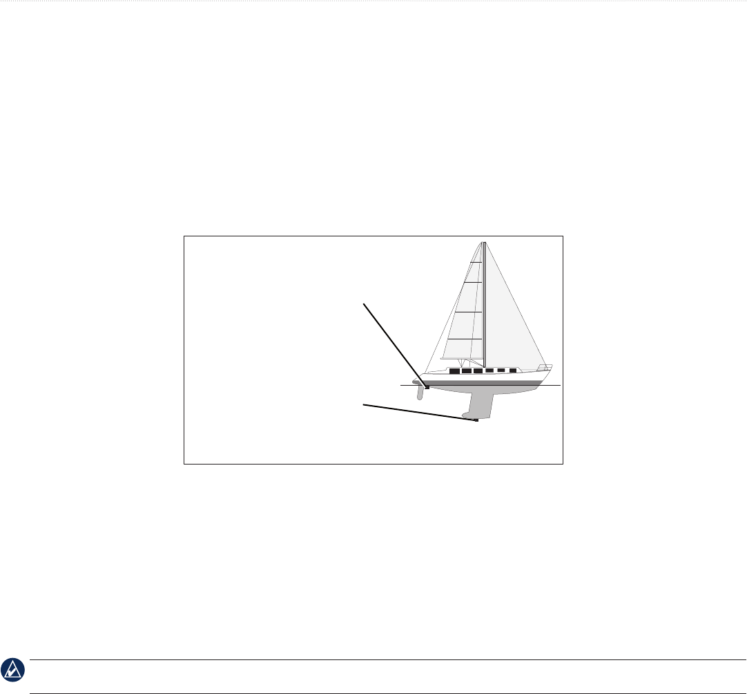
36 Technical Reference for Garmin NMEA 2000 Products
NMEA 2000 Checklist
Intelliducer (Intelligent Depth Transducer–Transom Mount and Thru-Hull)
Setting the Keel Offset
Adjust the to display a depth reading from the water line or from the lowest point of the boat (keel) rather than the actual location
of the Intelliducer.
To adjust the keel offset:
1. While viewing the NMEA 2000 device conguration menu, select a specic Intelliducer and select Cong > Keel Offset.
2. Enter the measured distance from the Intelliducer location to the water line or to the keel of the boat.
• If you are measuring down to the keel (Intelliducer installed at the water line), enter a (+) positive number.
• If you are measuring up to the water line (Intelliducer installed on the keel), enter a (-) negative number.
Keel Offset
Enter a (+) positive number
to show depth at the
bottom of the keel.
Intelliducer at the water line
Enter a (-) negative
number to show depth at
the surface.
Intelliducer at the bottom
of the keel
GWS 10 (Garmin Wind Sensor)
Conguring the Wind Angle Offset (Orientation)
When mounting the sensor, you must adjust the angle offset if you did not orient the GWS 10 as described in the GWS 10 Installation
Instructions.
To congure the wind angle offset (orientation):
1. While viewing the NMEA 2000 device information, select Cong > Wind Angle Offset.
2. Select the angle in degrees to adjust for the difference in orientation.
The angles are congured clockwise around the mast of the boat. For example, 90 degrees is on the starboard side of the boat, and 270 degrees is
on the port side.
Conguring the Wind Speed Filter
The wind speed lter governs how quickly the NMEA 2000-compatible display device shows a change in the wind speed. A lower lter setting
shows changes in the wind speed more gradually, and may stabilize the display.
To congure the wind speed lter:
1. While viewing the NMEA 2000 device information, select Cong > Wind Speed Filter.
2. Choose from the following options to adjust the lter settings.
• Off—the wind speed data is not ltered.
• On—select a lower number to show a change in the wind speed more gradually, and help the gauge needle or wind speed number to
move or change more steadily.
• Auto—automatically adjusts the lter settings based on wind conditions.

Technical Reference for Garmin NMEA 2000 Products 37
NMEA 2000 Checklist
Conguring the Wind Angle Filter
The wind angle lter governs how quickly the NMEA 2000-compatible display device shows a change in the wind angle. A lower lter setting
shows changes in the wind angle more gradually, and may stabilize the display.
To congure the wind angle lter:
1. While viewing the NMEA 2000 device information, select Cong > Wind Angle Filter.
2. Choose from the following options to adjust the lter settings.
• Off—the wind angle data is not ltered.
• On—select a lower number to update the display device less often, and help the gauge needle or wind angle number to move or change
more steadily.
• Auto—automatically adjusts the lter settings based on wind conditions.
Conguring the GWS 10 if the Filter and Offset Selections Are Not Displayed
Depending on the version of software loaded on your Garmin marine instrument, the specic conguration options may not be displayed on the
conguration screens.
To congure the wind angle offset if the menu option is not displayed:
1. Select Generic Conguration to specify data for the lter and offset settings.
2. Enter the following command: “ANGLEOFFSET=”
3. Follow the command with a number between 0 and 359, in degrees (for example: ANGLEOFFSET=180).
To congure the wind angle lter if the menu option is not displayed:
1. Select Generic Conguration to specify data for the lter and offset settings.
2. Enter the following command: “ANGLEFILTER=”
3. Follow the command with a number between 0 and 254, representing a time constant in increments of 0.25 second, or 255 to represent the
Automatic setting (for example: ANGLEFILTER=12).
To congure the wind speed lter:
1. Select Generic Conguration to specify data for the lter and offset settings.
2. Enter the following command: “SPEEDFILTER=”
3. Follow the command with a number between 0 and 254, representing a time constant in increments of 0.25 second, or 255 to represent the
Automatic setting (for example: SPEEDFILTER=215).
NMEA 2000 Checklist
Use this checklist to conrm your NMEA 2000 installation.
Is the NMEA 2000 network connected to power, and is the power balanced correctly on the network? (page 5)
Is the NMEA 2000 network power connected through the ignition switch–if not, did you install a switch? (page 5)
Is the NMEA 2000 power cable grounded? Is the bare wire connected to the same ground location? (page 5)
Is the NMEA 2000 network backbone built using linear construction? (page 4)
Are there terminators on both ends of the NMEA 2000 network? (page 7)
Are all drop cables less than 20 ft. (6 m)? (page 8)
For the latest free software updates (excluding map data) throughout the life of your
Garmin products, visit the Garmin Web site at www.garmin.com.
© 2009–2012 Garmin Ltd. or its subsidiaries
Garmin International, Inc.
1200 East 151st Street, Olathe, Kansas 66062, USA
Garmin (Europe) Ltd.
Liberty House, Hounsdown Business Park, Southampton, Hampshire, SO40 9LR UK
Garmin Corporation
No. 68, Zhangshu 2nd Road, Xizhi Dist., New Taipei City, 221, Taiwan (R.O.C.)
www.garmin.com
March 2012 Part Number 190-00891-00_0D Printed in Taiwan
