Garmin Mdl Rev 11 Sa01456Wi D System Maintenance Manual 190 00682 01_0G_xx Xx Xxxx
2015-05-27
: Garmin Garmin-Mdl-Rev-11-Sa01456Wi-D-System-Maintenance-Manual-720709 garmin-mdl-rev-11-sa01456wi-d-system-maintenance-manual-720709 garmin pdf
Open the PDF directly: View PDF ![]() .
.
Page Count: 300 [warning: Documents this large are best viewed by clicking the View PDF Link!]

190-00682-01 March 2014 Revision G
G1000 / GFC 700
System Maintenance Manual
Hawker Beechcraft
Model C90A/C90GT/C90GTi King Air
Contains Instructions
For Continued Airworthiness
For STC #SA01456WI-D

This page intentionally left blank.
Page A G1000/GFC700 System Maintenance Manual – C90A/C90GT/C90GTi King Air
Revision G 190-00682-01
© Copyright 2007-2014
Garmin Ltd. or its subsidiaries
All Rights Reserved
Except as expressly provided herein, no part of this manual may be reproduced, copied, transmitted,
disseminated, downloaded or stored in any storage medium, for any purpose without the express prior
written consent of Garmin. Garmin hereby grants permission to download a single copy of this manual
and of any revision to this manual onto a hard drive or other electronic storage medium to be viewed and
to print one copy of this manual or of any revision hereto, provided that such electronic or printed copy of
this manual or revision must contain the complete text of this copyright notice and provided further that
any unauthorized commercial distribution of this manual or any revision hereto is strictly prohibited.
Garmin International, Inc.
1200 E. 151
st
Street
Olathe, KS 66062 USA
Telephone: 913-397-8200
www.garmin.com
Garmin (Europe) Ltd.
Liberty House
Bulls Copse Road
Hounsdown Business Park
Southampton, SO40 9RB, UK
Phone: +44 (0) 23 8052 4000
Fax: +44 (0) 23 8052 4004
RECORD OF REVISIONS
Revision
Revision Date
Description
ECO #
C 02/18/2008 Updated Sections 1.1, 3.8, 3.9, 4.1, 4.4, 4.7, 4.14
and 4.15. Added Sections 7.21 and 7.22
51033
D 02/15/2010 Updated G1000 System Software Version to
0636.02. Add Loader Card Creation procedure
Section 3.8.2. Add SVS/Pathways.
71674
E 10/17/2012 Updated G1000 System Software Version to
0636.03. Added ESP. Misc updates.
95142
F 11/5/2012 Minor change update (clerical) 95629
G 03/14/2014 Added two configurations to include Beech factory
equipped three-bladed propellor aircraft.
112589
DOCUMENT PAGINATION
Section
Pagination
Table of Contents i – vi
Section 1 1-1 – 1-6
Section 2 2-1 – 2-14
Section 3 3-1 – 3-54
Section 4 4-1 – 4-40
Section 5 5-1 – 5-88
Section 6 6-1 – 6-18
Section 7 7-1 – 7-56
Section 8 8-1 – 8-14

Page B G1000/GFC700 System Maintenance Manual – C90A/C90GT/C90GTi King Air
Revision G 190-00682-01
INFORMATION SUBJECT TO EXPORT CONTROL LAWS
This document may contain information which is subject to the Export Administration Regulations
(“EAR”) issued by the United States Department of Commerce (15 CFR, Chapter VII Subchapter C) and
which may not be exported, released or disclosed to foreign nationals inside or outside the United States
without first obtaining an export license. The preceding statement is required to be included on any and
all reproductions in whole or in part of this manual.
This product, its packaging, and its components contain chemicals known to the State of California to
cause cancer, birth defects, or reproductive harm. This Notice is being provided in accordance with
California's Proposition 65. If you have any questions or would like additional information, please refer
to our web site at www.garmin.com/prop65.
The GDU lens is coated with a special anti-reflective coating that is very sensitive to skin oils, waxes and
abrasive cleaners. CLEANERS CONTAINING AMMONIA WILL HARM THE ANTI-REFLECTIVE
COATING. It is very important to clean the lens using a clean, lint-free cloth and an eyeglass lens
cleaner that is specified as safe for anti-reflective coatings.
All G1000 screen shots used in this document are current at the time of publication. Screen shots are
intended to provide visual reference only. All information depicted in screen shots, including software
file names, versions and part numbers, is subject to change and may not be up to date.
CAUTION
WARNING
IMPORTANT

G1000/GFC700 System Maintenance Manual – C90A/C90GT/C90GTi King Air Page i
190-00682-01 Revision G
TABLE OF CONTENTS
PARAGRAPH PAGE
1 INTRODUCTION ............................................................................................................................ 1-1
1.1 C
ONTENT
,
S
COPE
,
P
URPOSE
........................................................................................................ 1-1
1.2 O
RGANIZATION
........................................................................................................................... 1-3
1.3 D
EFINITIONS
/A
BBREVIATIONS
.................................................................................................... 1-4
1.4 P
UBLICATIONS
............................................................................................................................. 1-5
1.5 R
EVISION AND
D
ISTRIBUTION
..................................................................................................... 1-6
2 SYSTEM DESCRIPTION ............................................................................................................... 2-1
2.1 E
QUIPMENT
D
ESCRIPTIONS
......................................................................................................... 2-1
2.2 G1000
O
PTIONAL
I
NTERFACES
................................................................................................... 2-9
2.3 E
LECTRICAL
P
OWER
D
ISTRIBUTION
.......................................................................................... 2-10
2.4 S
HIELD
B
LOCK
G
ROUNDS
......................................................................................................... 2-12
2.5 G1000
/GFC700
B
LOCK
D
IAGRAM
........................................................................................... 2-13
3 G1000 CONTROL & OPERATION .............................................................................................. 3-1
3.1 GDU
1040A
AND
GDU
1500
D
ISPLAYS
..................................................................................... 3-1
3.2 GCU
475
-
MFD
C
ONTROLLER
................................................................................................... 3-3
3.3 GMC
710
-
AFCS
C
ONTROLS
..................................................................................................... 3-3
3.4 GMA
1347D
A
UDIO
P
ANEL
........................................................................................................ 3-4
3.5 G1000
N
ORMAL
M
ODE
............................................................................................................... 3-6
3.6 R
EVERSIONARY
M
ODE
................................................................................................................ 3-7
3.7 C
ONFIGURATION
M
ODE
O
VERVIEW
............................................................................................ 3-8
3.8 G1000
/
GFC
700
S
OFTWARE
I
NFORMATION
............................................................................ 3-13
3.9 G1000
S
OFTWARE
/C
ONFIGURATION
P
ROCEDURE
.................................................................... 3-25
3.10 A
IRCRAFT
R
EGISTRATION
N
UMBER
E
NTRY
.............................................................................. 3-52
3.11 S
PLASH
S
CREEN
L
OADING
........................................................................................................ 3-52
3.12 C
LEARING
D
EFAULT
U
SER
S
ETTINGS
....................................................................................... 3-53
4 INSTRUCTIONS FOR CONTINUED AIRWORTHINESS ........................................................ 4-1
4.1 A
IRWORTHINESS
L
IMITATIONS
................................................................................................... 4-1
4.2 S
ERVICING
I
NFORMATION
........................................................................................................... 4-3
4.3 M
AINTENANCE
I
NTERVALS
......................................................................................................... 4-5
4.4 V
ISUAL
I
NSPECTION
.................................................................................................................. 4-10
4.5 E
LECTRICAL
B
ONDING
T
EST
..................................................................................................... 4-15
4.6 GRS
77
E
ARTH
M
AGNETIC
F
IELD
U
PDATES
............................................................................. 4-18
4.7 GSA
8X
G
REASING
P
ROCEDURE
............................................................................................... 4-18
4.8 F
LAPS
-
IN
-M
OTION
D
ISCRETE
I
NPUT
C
HECK
............................................................................. 4-19
4.9 S
LIP
C
LUTCH
T
ORQUE
C
HECK
P
ROCEDURE AND
S
ERVO
C
URRENT
D
ISPLAY
C
HECK
.............. 4-20
4.10 G1000
R
EDUNDANT
C
ONNECTION
C
HECK
............................................................................... 4-28
4.11 E
NGINE
D
ATA
C
HECK
............................................................................................................... 4-31
4.12 T
RIM
A
NNUNCIATOR
C
HECK
..................................................................................................... 4-33
4.13 G1000
M
ISCOMPARE
C
HECKS
................................................................................................... 4-34
4.14 N
OSE
A
VIONICS
C
OMPARTMENT
F
ANS
O
PERATIONAL
C
HECK
................................................ 4-36
4.15 I
NSTRUMENT
P
ANEL
F
ANS
O
PERATIONAL
C
HECK
.................................................................... 4-36
4.16 S
TANDBY
B
ATTERY
P
ERIODIC
C
HECKS
.................................................................................... 4-36
5 TROUBLESHOOTING ................................................................................................................... 5-1
5.1 G1000
A
LERTING
S
YSTEM
.......................................................................................................... 5-2
5.2 S
YSTEM
A
NNUNCIATIONS
........................................................................................................... 5-4

Page ii G1000/GFC700 System Maintenance Manual – C90A/C90GT/C90GTi King Air
Revision G 190-00682-01
5.3 C90A/C90GT/C90GT
I
S
PECIFIC
A
LERTS
................................................................................. 5-27
5.4 TAWS
T
ROUBLESHOOTING
...................................................................................................... 5-28
5.5 S
YNTHETIC
V
ISION AND
P
ATHWAYS
T
ROUBLESHOOTING
........................................................ 5-29
5.6 GFC
700
AFCS
T
ROUBLESHOOTING
........................................................................................ 5-30
5.7 B
ACKUP
C
OMMUNICATIONS
P
ATH
C
HECKS
.............................................................................. 5-46
5.8 GDU
104X
T
ROUBLESHOOTING
............................................................................................... 5-47
5.9 GDU
104X
A
LERTS
................................................................................................................... 5-49
5.10 GIA
63
T
ROUBLESHOOTING
...................................................................................................... 5-57
5.11 GIA
A
LERT
M
ESSAGES
............................................................................................................. 5-59
5.12 GEA
T
ROUBLESHOOTING
.......................................................................................................... 5-66
5.13 GTX
T
ROUBLESHOOTING
.......................................................................................................... 5-67
5.14 GDL
69A
T
ROUBLESHOOTING
.................................................................................................. 5-68
5.15 GRS
77/GMU
44
T
ROUBLESHOOTING
...................................................................................... 5-70
5.16 GDC
74B
T
ROUBLESHOOTING
.................................................................................................. 5-76
5.17 GWX
68
T
ROUBLESHOOTING
................................................................................................... 5-77
5.18 GMC
710
T
ROUBLESHOOTING
.................................................................................................. 5-78
5.19 GCU
475
T
ROUBLESHOOTING
................................................................................................... 5-79
5.20 S
OFTWARE
/C
ONFIGURATION
T
ROUBLESHOOTING
................................................................... 5-80
5.21 B
ACKSHELL
C
ONNECTORS
........................................................................................................ 5-82
5.22 S
TANDBY
A
TTITUDE
I
NDICATOR
T
ROUBLESHOOTING
.............................................................. 5-86
5.23 S
TANDBY
A
IRSPEED
I
NDICATOR
T
ROUBLESHOOTING
.............................................................. 5-86
5.24 S
TANDBY
A
LTIMETER
T
ROUBLESHOOTING
.............................................................................. 5-87
5.25 S
TANDBY
B
ATTERY
T
ROUBLESHOOTING
.................................................................................. 5-87
6 EQUIPMENT REMOVAL & REPLACEMENT ......................................................................... 6-1
6.1 GDU
1040A/1500 ....................................................................................................................... 6-2
6.2 GMA
1347D
A
UDIO
P
ANEL
........................................................................................................ 6-2
6.3 GIA
63W
I
NTEGRATED
A
VIONICS
U
NITS
.................................................................................... 6-3
6.4 GEA
71
E
NGINE
/A
IRFRAME
U
NIT
............................................................................................... 6-3
6.5 GTX
33
T
RANSPONDER
............................................................................................................... 6-4
6.6 GDC
74B
A
IR
D
ATA
C
OMPUTER
................................................................................................ 6-4
6.7 GTP
59
OAT
P
ROBE
.................................................................................................................... 6-4
6.8 GRS
77
AHRS ............................................................................................................................. 6-5
6.9 GMU
44
M
AGNETOMETER
.......................................................................................................... 6-5
6.10 GDL
69A ..................................................................................................................................... 6-5
6.11 GSA
80/81
S
ERVOS
..................................................................................................................... 6-6
6.12 GSM
85A
/
GSM
86
S
ERVO
M
OUNTS
......................................................................................... 6-6
6.13 GCU
475...................................................................................................................................... 6-7
6.14 GMC
710 ..................................................................................................................................... 6-7
6.15 GWX
68 ...................................................................................................................................... 6-8
6.16 C
ONFIGURATION
M
ODULE
R
EMOVAL
&
R
EPLACEMENT
............................................................ 6-9
6.17 GEA
71
B
ACKSHELL
T
HERMOCOUPLE
R
EMOVAL
&
R
EPLACEMENT
....................................... 6-11
6.18 GPS/WAAS
A
NTENNAS
............................................................................................................ 6-12
6.19 E
NGINE
S
IGNAL
C
ONDITIONERS
................................................................................................ 6-12
6.20 S
ENIOR
A
EROSPACE
PC920
S
IGNAL
C
ONDITIONING
U
NIT
....................................................... 6-13
6.21 I
NSTRUMENT
P
ANEL
A
NNUNCIATORS
(P
ROP
S
YNCH AND
S
TANDBY
B
ATTERY
) ...................... 6-14
6.22 L-3
A
VIONICS
(BF
G
OODRICH
)
PS-835(C
OR
D
M
ODEL
)
E
MERGENCY
B
ATTERY
................... 6-14
6.23 S
TANDBY
A
IRSPEED
I
NDICATOR
............................................................................................... 6-15
6.24 S
TANDBY
A
LTIMETER
............................................................................................................... 6-15
6.25 S
TANDBY
A
TTITUDE
I
NDICATOR
.............................................................................................. 6-16
6.26 A
VIONICS
C
OOLING
F
ANS
......................................................................................................... 6-16
6.27 GDU
C
OOLING
F
ANS
................................................................................................................. 6-17
7 G1000 EQUIPMENT CONFIGURATION & TESTING ............................................................. 7-1

G1000/GFC700 System Maintenance Manual – C90A/C90GT/C90GTi King Air Page iii
190-00682-01 Revision G
7.1 GDU
1040/1500
MFD
&
PFD ..................................................................................................... 7-1
7.2 GMA
1347D
A
UDIO
P
ANEL
........................................................................................................ 7-3
7.3 GIA
63W
I
NTEGRATED
A
VIONICS
U
NIT
................................................................................... 7-10
7.4 GEA
71
E
NGINE
/A
IRFRAME
U
NIT
............................................................................................. 7-13
7.5 GTX
33
T
RANSPONDER
............................................................................................................. 7-20
7.6 GDC
74B
A
IR
D
ATA
C
OMPUTER
.............................................................................................. 7-22
7.7 GRS
77
AHRS
/
GMU
44
M
AGNETOMETER
............................................................................. 7-26
7.8 GDL
69A
XM
D
ATA
L
INK
........................................................................................................ 7-36
7.9 GSA
80/81
S
ERVOS
................................................................................................................... 7-36
7.10 GCU
475
FMS
C
ONTROLLER
.................................................................................................... 7-37
7.11 GMC
710
AFCS
C
ONTROLLER
................................................................................................. 7-38
7.12 GWX
68
W
EATHER
R
ADAR
..................................................................................................... 7-39
7.13 T
RAFFIC
(N
ON
-G
ARMIN
)
S
YSTEM
F
UNCTIONAL
C
HECK
.......................................................... 7-40
7.14 L
IGHTNING
D
ETECTION
F
UNCTIONAL
C
HECK
.......................................................................... 7-41
7.15 TAWS
F
UNCTIONAL
C
HECK
..................................................................................................... 7-43
7.16 F
LITE
C
HARTS
F
UNCTIONAL
C
HECK
.......................................................................................... 7-44
7.17 C
HART
V
IEW
F
UNCTIONAL
C
HECK
............................................................................................ 7-45
7.18 S
AFE
T
AXI
F
UNCTIONAL
C
HECK
................................................................................................ 7-46
7.19 DME
F
UNCTIONAL
C
HECK
....................................................................................................... 7-47
7.20 ADF
F
UNCTIONAL
C
HECK
........................................................................................................ 7-48
7.21 A
IRCRAFT
W
EIGHT
C
ONFIGURATION
F
UNCTIONAL
C
HECK
..................................................... 7-48
7.22 W
EIGHT ON
W
HEELS AND
L
OW
S
PEED
A
WARENESS
B
AND
T
EST
............................................ 7-53
7.23 ESP
F
UNCTIONAL
C
HECK
......................................................................................................... 7-54
8 SYSTEM RETURN TO SERVICE PROCEDURE ...................................................................... 8-1
8.1 B
ACKUP
P
ATH
S
YSTEM
T
ESTING
................................................................................................ 8-2
8.2 GFC
700
G
ROUND
C
HECKOUT
.................................................................................................. 8-10
8.3 M
AINTENANCE
R
ECORDS
.......................................................................................................... 8-14

Page iv G1000/GFC700 System Maintenance Manual – C90A/C90GT/C90GTi King Air
Revision G 190-00682-01
LIST OF ILLUSTRATIONS
FIGURE PAGE
Figure 2-1. C90 Electrical Distribution ................................................................................................... 2-11
Figure 2-2. Avionics Master Power Schematic ...................................................................................... 2-11
Figure 2-3. G1000 Component Power Sources ...................................................................................... 2-12
Figure 2-4. G1000/GFC 700 Block Diagram .......................................................................................... 2-13
Figure 3-1. GDU 1040A Control Interface ............................................................................................... 3-1
Figure 3-2. GDU 1500 Control Interface .................................................................................................. 3-2
Figure 3-3. G1000 Softkeys ...................................................................................................................... 3-2
Figure 3-4. MFD Controls (GCU 475) ..................................................................................................... 3-3
Figure 3-5. AFCS Controls (GMC 710) ................................................................................................... 3-3
Figure 3-6. GMA 1347D PN 011-01257-00 Controls .............................................................................. 3-4
Figure 3-7. GMA 1347D PN 011-01257-20 Controls .............................................................................. 3-5
Figure 3-8. Normal Mode ......................................................................................................................... 3-6
Figure 3-9. Manual Reversion with MFD failure ..................................................................................... 3-7
Figure 3-10. Manual Reversion with pilot PFD failure ............................................................................ 3-7
Figure 3-11. SET and ACTV Softkeys and Columns ............................................................................... 3-9
Figure 3-12. Loss of Communication ..................................................................................................... 3-10
Figure 3-13. Configuration Status ........................................................................................................... 3-10
Figure 3-14. Data Transmission Indicators ............................................................................................. 3-11
Figure 3-15. G1000 LRU Configuration File Storage ............................................................................ 3-23
Figure 3-16. GRS/GDC Configuration Settings Storage ........................................................................ 3-24
Figure 3-17. Software/Configuration Overview ..................................................................................... 3-25
Figure 3-18. System Upload Page........................................................................................................... 3-27
Figure 3-19. System Status ..................................................................................................................... 3-29
Figure 3-20. ESP Support Configuration ................................................................................................. 3-42
Figure 3-21. Servo Mount Configuration Verification ............................................................................ 3-43
Figure 3-22. Navigation Database Synchronization ................................................................................ 3-49
Figure 3-24. Aircraft Registration ........................................................................................................... 3-52
Figure 4-1. Servo Gear ............................................................................................................................. 4-18
Figure 4-2 GFC Status Page ................................................................................................................... 4-20
Figure 4-3 GFC Status Page ................................................................................................................... 4-22
Figure 4-4 GFC Status Page ................................................................................................................... 4-27
Figure 4-5, Standby Battery ..................................................................................................................... 4-37
Figure 4-6, Power Supply Connection .................................................................................................... 4-39
Figure 5-1. AUX – System Status Page .................................................................................................... 5-1
Figure 5-2. Alerts & Annunciations .......................................................................................................... 5-2
Figure 5-3. ADVISORY Softkey Annunciation ....................................................................................... 5-2
Figure 5-4. System Annunciations ............................................................................................................ 5-4
Figure 5-5, AFCS Annunciation Field .................................................................................................... 5-30
Figure 5-6. GFC Status Page .................................................................................................................. 5-33
Figure 5-7. Magnetometer Interference Test .......................................................................................... 5-73
Figure 5-8. Magnetometer Interference Test Complete .......................................................................... 5-75
Figure 5-9. GIA 63W Backshell Connectors .......................................................................................... 5-82
Figure 5-10. GEA 71 Backshell Connectors ........................................................................................... 5-83
Figure 5-11. GMA 1347D Backshell Connectors ................................................................................... 5-83
Figure 5-12. GTX 33/33D Backshell Connectors ................................................................................... 5-83
Figure 5-13. GDU 1040A/1500 Backshell Connector (P10401 or P15001)........................................... 5-84
Figure 5-14. GRS 77 Backshell Connector (P771) ................................................................................. 5-84
Figure 5-15. GDC 74B Backshell Connector (P74B1) ........................................................................... 5-84
Figure 5-16. GDL 69A Backshell Connector (P69A1) ........................................................................... 5-84
Figure 5-17. GCU 475 Backshell Connector (P4751) ............................................................................ 5-85
Figure 5-18. GMC 710 Backshell Connector (P7101)............................................................................ 5-85

G1000/GFC700 System Maintenance Manual – C90A/C90GT/C90GTi King Air Page v
190-00682-01 Revision G
Figure 5-19. GWX 68 Backshell Connector (P681) ............................................................................... 5-85
Figure 5-20, Signal Conditioner Mating Connector (PVIB1) ................................................................. 5-85
Figure 6-1. Configuration Module Installation ......................................................................................... 6-9
Figure 6-2. GEA Backshell Thermocouple ............................................................................................. 6-11
Figure 7-1. G1000 Normal Mode Check .................................................................................................. 7-2
Figure 7-2. Marker Beacon Symbology .................................................................................................... 7-6
Figure 7-3. AUX – GPS STATUS Page (MFD) ..................................................................................... 7-10
Figure 7-4. Normal Engine Instrument Markings (MFD) ...................................................................... 7-13
Figure 7-5, Aircraft Registration .............................................................................................................. 7-20
Figure 7-6. GRS 77 Pitch/Roll Offset Calibration Page ......................................................................... 7-28
Figure 7-7, Engine Run-Up Test Page ..................................................................................................... 7-33
Figure 7-8. Normal Mode AHRS Check ................................................................................................ 7-35
Figure 7-9. Low Speed Awareness Band Symbolization ........................................................................ 7-53
Figure 8-1. GDU Data Verification (ARINC 429) .................................................................................... 8-7
Figure 8-2. GIA Data Verification (ARINC429/RS-232) .......................................................................... 8-8
Figure 8-3. GIA Data Verification (RS-485) ............................................................................................. 8-9
Figure 8-4. Pre-Flight Test ...................................................................................................................... 8-10
LIST OF TABLES
TABLE PAGE
Table 1-1. MDL Configurations Summary ............................................................................................... 1-1
Table 1-2. Required Documents ............................................................................................................... 1-5
Table 1-3. Reference Publications ............................................................................................................ 1-6
Table 3-1. Data Indicator Symbols ......................................................................................................... 3-11
Table 3-2. LRU to Configuration File Relationship ............................................................................... 3-21
Table 3-3. Default Airframe Weight Configurations .............................................................................. 3-33
Table 3-4. Optional Airframe Weight Configurations for SW Version 0636.01 .................................... 3-33
Table 3-5. Optional Airframe Weight Configurations for SW Version 0636.02 and Subs .................... 3-34
Table 4-1. Maintenance Intervals.............................................................................................................. 4-5
Table 4-2. Discontinued Maintenance Intervals ....................................................................................... 4-9
Table 4-3. Nose Section Visual Inspection Procedure ............................................................................ 4-10
Table 4-4. Nose Avionics Compartment Visual Inspection Procedure .................................................. 4-10
Table 4-5. Pilot’s Compartment Visual Inspection Procedure ................................................................ 4-11
Table 4-6. Instrument Panel G1000 Equipment Visual Inspection Procedure ....................................... 4-12
Table 4-7. Cabin Area Visual Inspection Procedure ............................................................................... 4-13
Table 4-8. Rear Fuselage and Empennage Visual Inspection Procedure ................................................ 4-14
Table 4-9, Lightning Strike Inspection Procedure ................................................................................... 4-14
Table 4-10. Measured Torque ................................................................................................................. 4-24
Table 4-11. Slip Clutch Torque Settings ................................................................................................. 4-26
Table 4-12, Standby Battery Required Equipment .................................................................................. 4-37
Table 5-1, SVS Troubleshooting ............................................................................................................. 5-29
Table 5-2, SVS-Related Alert Messages ................................................................................................. 5-29
Table 5-3. AFCS Annunciation Troubleshooting ................................................................................... 5-31
Table 5-4. AFCS General Troubleshooting ............................................................................................ 5-32
Table 5-5. Magnetometer Interference Test Sequence (Example) .......................................................... 5-74
Table 6-1. Configuration Module Kit – 011-00979-00 ............................................................................. 6-9
Table 6-2. Thermocouple Kit (011-00981-00) ....................................................................................... 6-11
Table 7-1. Airspeed and Altitude Table .................................................................................................. 7-24
Table 7-2. Vertical Speed Table ............................................................................................................. 7-25
Table 7-3. Required GRS/GMU Calibrations ......................................................................................... 7-27

Page vi G1000/GFC700 System Maintenance Manual – C90A/C90GT/C90GTi King Air
Revision G 190-00682-01
This page intentionally left blank

G1000/GFC700 System Maintenance Manual – C90A/C90GT/C90GTi King Air Page 1-1
190-00682-01 Revision G
1 INTRODUCTION
1.1 Content, Scope, Purpose
This document provides Instructions for Continued Airworthiness (ICA) for the Garmin G1000 integrated
avionics and GFC700 Automatic Flight Control System (AFCS) as installed in the C90A/C90GT/C90GTi
King Air, under STC #SA01456WI-D. This document satisfies the requirements for continued
airworthiness as defined by 14 CFR Part 23.1529 and Appendix G. Information in this document is
required to maintain the continued airworthiness of the G1000 and GFC700.
NOTE
Various procedures herein may require operating the aircraft on the ground for
extended periods. Do not conduct extended ground operations (in excess of 15
minutes) with cabin air temperatures above 40 degrees C.
1.1.1 Applicability
This document applies to all Model C90A/C90GT/C90GTi King Air aircraft (herein referred to also as
C90A/GT/GTi) equipped with the G1000 and optional GFC700 AFCS systems.
Modification of an aircraft by this Supplemental Type Certificate (STC) obligates the aircraft operator to
include the maintenance information provided by this document in the operator’s Aircraft Maintenance
Manual and the operator’s Aircraft Scheduled Maintenance Program.
1.1.2 Identifying an STC Configuration
Table 1-1 lists the approved configurations for this STC as defined by the Master Drawing List (MDL),
Garmin document 005-00375-30.
Software loads are governed primarily by the G1000 System Software Version number. The following
table identifies the System Software Version for this STC.
NOTE
G1000 System Software Version 0636.05 is added with STC MDL Rev. 11 and is the
recommended software. G1000 System Software Versions 0636.01, 0636.02, and 0636.03
will remain to support fielded aircraft. Software Version 0636.04 is not approved for
installation.
Table 1-1. MDL Configurations Summary
MDL
Configuration
Aircraft
Model
G1000 System
Software Version Notes
-1 C90A/C90GT King Air 0636.01 STC MDL Rev. 4 Approval
-1 C90A/C90GT King Air 0636.02 STC MDL Rev. 5 Approval
-1 C90A/C90GT/C90GTi King Air 0636.03 STC MDL Rev. 6 Approval
-1 C90A/C90GT/C90GTi King Air 0636.05 STC MDL Rev. 11 Approval
This STC addresses multiple C90A/GT/GTi configurations. These configuration variants are added by
loading the applicable airframe configuration and related options. Refer the General Arrangement
Drawing, Garmin Part Number 005-00375-22, for additional information.

Page 1-2 G1000/GFC700 System Maintenance Manual – C90A/C90GT/C90GTi King Air
Revision G 190-00682-01
IMPORTANT!
If the technician is unsure of an aircraft’s STC Configuration, perform the
following steps:
1. Inspect the aircraft maintenance logs for records of which STC configuration is installed. Inspect
aircraft records for signs of other alterations, including field updates and Service Bulletins.
2. Power on the G1000 system by setting the BAT switch to ON, then the EXT PWR switch to ON and
finally the AVIONICS MASTER switch to ON.
3. Following MFD power-up, observe upper right section of MFD splash screen for airframe
configuration.
OR
After acknowledgement of the splash screen, use the FMS knob on the GCU 475 controller to go to
the AUX – SYSTEM STATUS page on the MFD. In the AIRFRAME section (upper right corner,)
the display shows the current G1000 airframe configuration and system software version number.
The airframe configuration is shown in the AIRFRAME field and the system software version
number is shown in the following format: ‘System Software Version XXXX.XX’. It correlates to the
G1000 software used to load the software to the system:
EXAMPLE:
System Software Version
‘0636.02’
= G1000 Software P/N 006-B
0636-02
The G1000/GFC 700 C90 General Arrangement Drawing, Garmin Document 005-00375-22, defines
the approved G1000 software for this STC.

G1000/GFC700 System Maintenance Manual – C90A/C90GT/C90GTi King Air Page 1-3
190-00682-01 Revision G
1.2 Organization
The following outline briefly describes the organization of this manual:
Section 2: System Description
Provides a complete description of the type design change associated with installing the G1000
integrated cockpit system in the C90A/GT/GTi King Air. An overview of the G1000 and GFC 700
system interface is also provided.
Section 3: G1000 Control & Operation
Presents basic control and operation information specifically tailored to maintenance practices. Basic
G1000 Configuration Mode operation is also described.
Section 4: Instructions for Continued Airworthiness
Provides maintenance instructions for continued airworthiness of the G1000 and GFC 700 systems.
Section 5: Troubleshooting
Provides troubleshooting information to aid in diagnosing and resolving potential problems with the
G1000 and GFC 700 systems.
Section 6: G1000 Equipment Removal & Replacement
Gives instructions for the removal and replacement of G1000 and GFC700 equipment.
Section 7: G1000 Equipment Configuration & Testing
Gives instructions for loading software, configuring, and testing of G1000 equipment.
Section 8: System Return to Service Procedure
Specifies return-to-service procedures to be performed upon completion of maintenance of the G1000
system.

Page 1-4 G1000/GFC700 System Maintenance Manual – C90A/C90GT/C90GTi King Air
Revision G 190-00682-01
1.3 Definitions/Abbreviations
ADF: Automatic Direction Finder
ADTS: Air Data Test Set
AFCS: Automatic Flight Control System
AFM: Aircraft Flight Manual
AFMS: Aircraft Flight Manual Supplement
AHRS: Attitude Heading Reference System
CDU: Control Display Unit
CFR: Code of Federal Regulations
DME: Distance Measuring Equipment
EAU: Engine/Airframe Unit
ESP: Electronic Stability and Protection
GPS: Global Positioning System
HSDB: High-Speed Data Bus (Ethernet)
IAU: Integrated Avionics Unit
ICS: Inter-Com System
ITT: Interstage Turbine Temperature
LRU: Line Replaceable Unit
MFD: Multi-Function Flight Display
OAT: Outside Air Temperature
PFD: Primary Flight Display
STBY: Standby
STBY ATT: Standby Attitude Indicator
STBY ALT: Standby Altimeter
STBY A/S: Standby Airspeed Indicator
STC: Supplemental Type Certificate
TAWS: Terrain Awareness & Warning system
WAAS: Wide Area Augmentation System
VHF: Very High Frequency
1.3.1 Units of Measure
Unless otherwise stated, all units of measure are English units.

G1000/GFC700 System Maintenance Manual – C90A/C90GT/C90GTi King Air Page 1-5
190-00682-01 Revision G
1.4 Publications
The following documents are required by this maintenance manual to perform maintenance:
Table 1-2. Required Documents
Part Number Garmin Documents
005-00375-30 STC Master Drawing List
005-W0022-00 Wiring Diagram, G1000/GFC 700 King C90
005-00375-22 General Arrangement, G1000/GFC700 AFCS, King Air C90
005-00375-19 GWX 68 Radar Install, King Air C90A
005-00375-21 Antenna Install, King Air C90A
005-00375-28 Main Instrument Panel Installation, King Air C90
005-00375-34 Electrical Equipment Install, Nose Bay, King Air C90A
005-00375-41 Roll Servo Install, King Air C90A
005-00375-42 Yaw Servo Install, King Air C90A
005-00375-43 Pitch Servo Install, King Air C90A
005-00375-44 Pitch Trim Servo Install, King Air C90A
005-00375-53 Magnetometer Install, King Air C90A
005-00375-54 OAT Sensor Install, King Air C90A
005-00375-71 Standby Battery Install, King Air C90A
005-00375-78 Cabin Speaker Amplifier Installation, King Air C90
005-00375-79 Fwd Bulkhead Connector Plate Installation, King Air C90
320-00326-XX Wire Harness Assembly, G1000/GFC 700
005-00375-55 Wire Harness Routing, Nose, King Air C90
005-00375-56 Wire Harness Routing, Cabin, King Air C90
005-00375-31 Wire Harness Routing, Tail, King Air C90
005-00375-23 Control Wheel Modification,G1000/GFC 700, King Air C90
005-00375-25 Overhead Control Panel Modification, G1000/GFC 700, King Air C90A
005-00375-26 Pedestal Re-Configuration, King Air C90A
005-00375-29 Circuit Breaker Panel Modification, King Air C90A
005-00375-70 Circuit Breaker Panel Modification, King Air C90A
005-00375-83 Glareshield Lighting Modification, King Air C90
Hawker Beechcraft Documents
90-590024-11 King Air C90 Series Wiring Diagram Manual
90-590012-13 King Air Model 90 Series Maintenance Manual
101-590097-13 King Air Series Component Maintenance Manual
Other Documents
523-0772458-00611A Collins DME-42 Transceiver Repair Manual (If DME is installed)
9016182
Mid-Continent Instruments - Installation Manual and Operating Instructions,
4200 Series Attitude Indicator
Page 1-6 G1000/GFC700 System Maintenance Manual – C90A/C90GT/C90GTi King Air
Revision G 190-00682-01
85-292-1-1033
Signal Conditioner Installation Manual (Meggitt Sensing Systems)
TP-336
L-3 Avionics Systems – Emergency Power Supply Installation Manual, PS-835
NOTE
Drawings, associated with this project, which include C90, C90A, or C90A/C90GT in the title apply to
the C90A, C90GT, and C90GTi unless specifically otherwise stated within the drawing or elsewhere in
the STC data package.
The following publications are recommended to be on hand during the performance of maintenance
activities.
Table 1-3. Reference Publications
Part Number Garmin Document
190-00682-02 G1000/GFC 700, King Air C90A/C90GT Airplane Flight Manual
Supplement
190-00664-XX G1000/King Air C90A/C90GT Cockpit Reference Guide
190-00355-04 GDL 69/69A XM Satellite Radio Activation Instructions
190-00907-00 G1000 System Maintenance Manual
190-00303-72 GSA8X/GSM85(A) Installation Manual
190-00303-83 GSM 86 Installation Manual
Hawker Beechcraft Document
98-39006 Structural Inspection and Repair Manual
Generic installation manuals for individual Garmin LRUs are also available through the ‘Dealer Resource
Center’ section of the Garmin web site; refer to Section 1.5 for details.
1.5 Revision and Distribution
This document is required for maintaining the continued airworthiness of the aircraft. When this
document is revised, every page will be revised to indicate current revision level.
Garmin Dealers may obtain the latest revision of this document on the Garmin Dealer Resource Center
website.
Owner/operators may obtain the latest revision of this document from the https://fly.garmin.com/ Support
page, or by contacting a Garmin dealer, contacting Garmin Product Support at 913-397-8200, toll free
866-739-5687, or using around the world contact information on https://fly.garmin.com/.
A Garmin Service Bulletin describing the revision to this document will be sent to Garmin dealers if the
revision is determined to be significant.
G1000/GFC700 System Maintenance Manual – C90A/C90GT/C90GTi King Air Page 2-1
190-00682-01 Revision G
2 SYSTEM DESCRIPTION
2.1 Equipment Descriptions
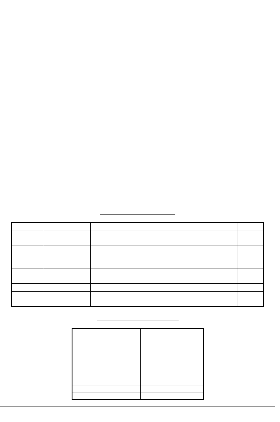
2.1.1 GDU 1040A PFD (2) & GDU 1500 MFD
Two Garmin GDU 1040A displays and one GDU 1500 display are installed in the King Air instrument
panel. The GDU 1040A units, 10.4 inch LCD displays with 1024x768 resolution, are configured as PFD 1
and PFD 2; the GDU 1500 unit, a 15 inch LCD display with 1024x768 resolution, is configured as a MFD.
All displays provide control and display of nearly all functions of the G1000 integrated cockpit system. The
PFD displays are located on either side of the MFD, with the stand-by instruments located between the
Pilot’s PFD (PFD 1) and the MFD. GMA 1347 Audio Panels are located outboard of each PFD.
Additionally, a GMC 710 AFCS Controller is located in the upper instrument panel, above the MFD, and a
GCU 475 is installed in the pedestal. The GCU 475 provides the control interface for the MFD.
The GDU 1500 communicates with the GDU 1040A units and the GDL 69A through a high-speed data bus
(HSDB) Ethernet connection. The GDU 1500 communicated with the GCU 475 via RS-232 digital
interface.
The GDU 1040A units communicate with each other and the GIA 63W units through a high-speed data bus
(HSDB) Ethernet connection.
Electrical power to PFD 1, MFD, and PFD 2 is provided by the triple-fed bus. The triple-fed bus is powered
by the battery and both generator buses. Additionally, a secondary power source is provided to PFD 1 by the
center bus, which is fed by both generator buses and the battery. Therefore, the displays power-up
immediately with external or aircraft power or battery operation.
All displays are installed in the King Air panel using ¼-turn fasteners. Three CDU cooling fans are also
installed behind the panel for PFD and MFD cooling.
Page 2-2 G1000/GFC700 System Maintenance Manual – C90A/C90GT/C90GTi King Air
Revision G 190-00682-01
2.1.2 GMA 1347D Audio Panel (2)
The Garmin GMA 1347D Audio Panel integrates NAV/COM digital audio, intercom system and marker
beacon controls. The C90 installation includes two GMA 1347 panels. The GMA 1347D panels provide
control of all cockpit intercom/mic systems as well as NAV/COM/ILS audio. The units also provide display
reversion mode control through a large red button. Power to the audio panels is provided by the avionics
bus. These units only power up when the avionics master switch is turned on. The GMA 1347D units
interface with the existing marker beacon antenna, as well as existing mic and phone jacks and oxygen mask
mic.
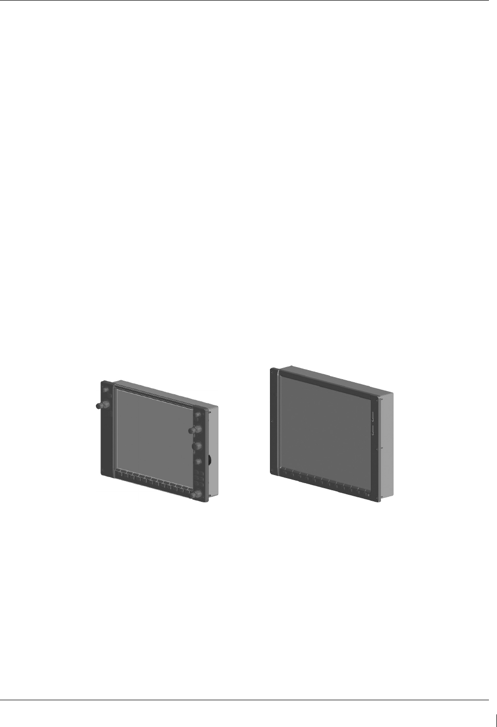
2.1.3 GMC 710 AFCS Control Unit
The dedicated AFCS controls on the GMC 710 allow crew control interface with the various GFC 700
autopilot / flight director functions. GMC 710 controls are discussed in detail in the G1000/King Air
C90A/C90GT/C90GTi Cockpit Reference Guide. The GMC 710 is powered by the triple fed bus.
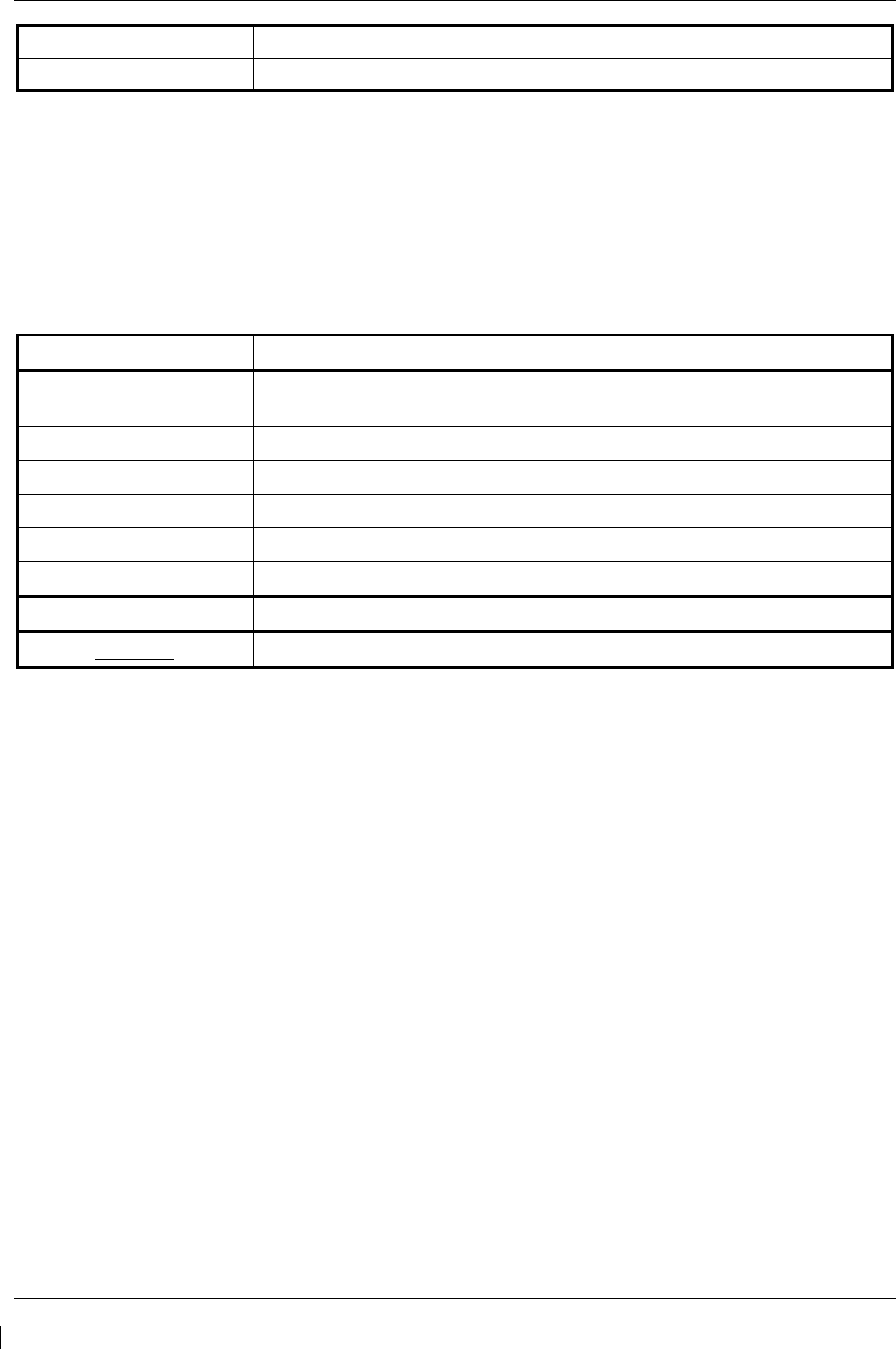
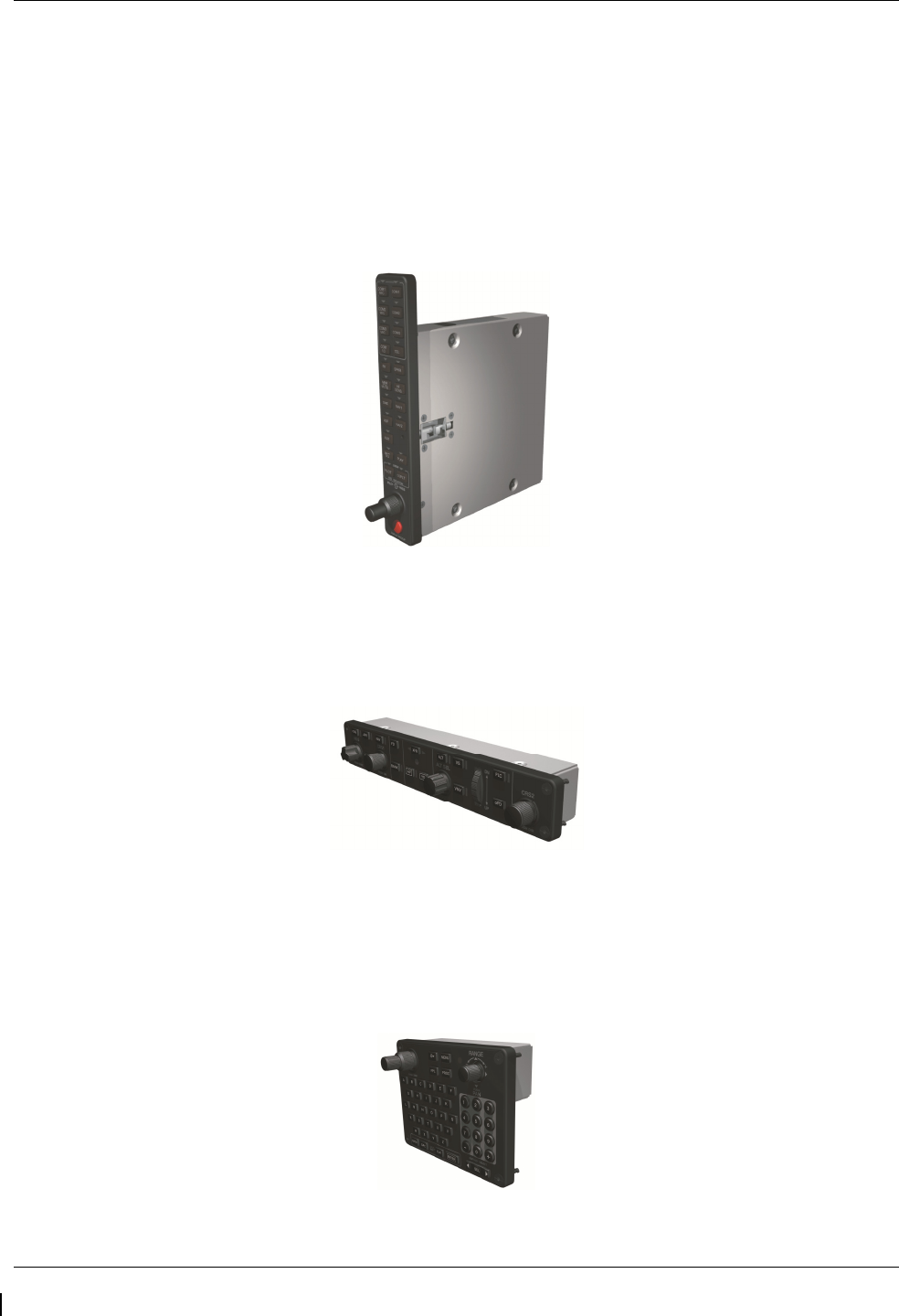
2.1.4 GCU 475 FMS Control Unit
The GCU 475 functions as the primary control interface to the GDU 1500 MFD. The GCU 475 provides
alphanumeric, softkey, and flight planning function keys used to interface with the G1000; the MFD does not
possess any knobs or controls other than softkeys. The GCU 475 is powered by the triple-fed bus. Detailed
instructions regarding the controls are discussed in the G1000 Cockpit Reference Guide.
G1000/GFC700 System Maintenance Manual – C90A/C90GT/C90GTi King Air Page 2-3
190-00682-01 Revision G
2.1.5 GIA 63W Integrated Avionics Unit (2)
Two Garmin GIA 63W Integrated Avionics Units (IAUs) contains the VHF COM/NAV receivers, WAAS
GPS receiver, Flight Director, and system integration microprocessors. The GIAs also serve as a
communication interface to all other G1000 LRUs in the system. Each GIA 63W communicates directly
with the on-side GDU 1040A display using a HSDB Ethernet connection. Both GIAs are located remotely
in the nose equipment bay.
Power is provided to both GIAs by the triple-fed bus. The triple-fed bus is powered by the battery and both
generator buses. Additionally, a secondary power source is provided to GIA1 by the center bus, which is fed
by both generator buses and the battery. The GIA 1’s COMM power supply (COM 1) is provided by No.1
Avionics Bus. GIA 2’s COMM power supply (COM 2) is provided by No.2 Avionics Bus. Therefore,
both GIAs power-up immediately with external or aircraft power or battery operation, with the exception of
both COMs, which will become active after selection of Avionics Master on. Both GIA 63s interface to the
following equipment:
•
Existing VOR/LOC/Glideslope Antenna System
•
Existing VHF COM #1 & #2 Antennas
•
GPS/WAAS Antennas
•
GMA 1347D, #1 & #2
•
GEA 71, #1 & #2
•
GDU 1040A, #1 & #2
•
GSA 80 (all) and GSA 81
•
GRS 77, #1 & #2
•
Traffic System (if installed)
The GIA 63W #1 interfaces to the following additional equipment:
•
GDC 74B #1
•
GTX 33 #1
•
DME 42 (if installed)
The GIA 63W #2 interfaces to the following additional equipment:
•
GDC 74B #2
•
GTX 33 #2
•
ADF 60 (if installed)
•
Stormscope (if installed)
Page 2-4 G1000/GFC700 System Maintenance Manual – C90A/C90GT/C90GTi King Air
Revision G 190-00682-01
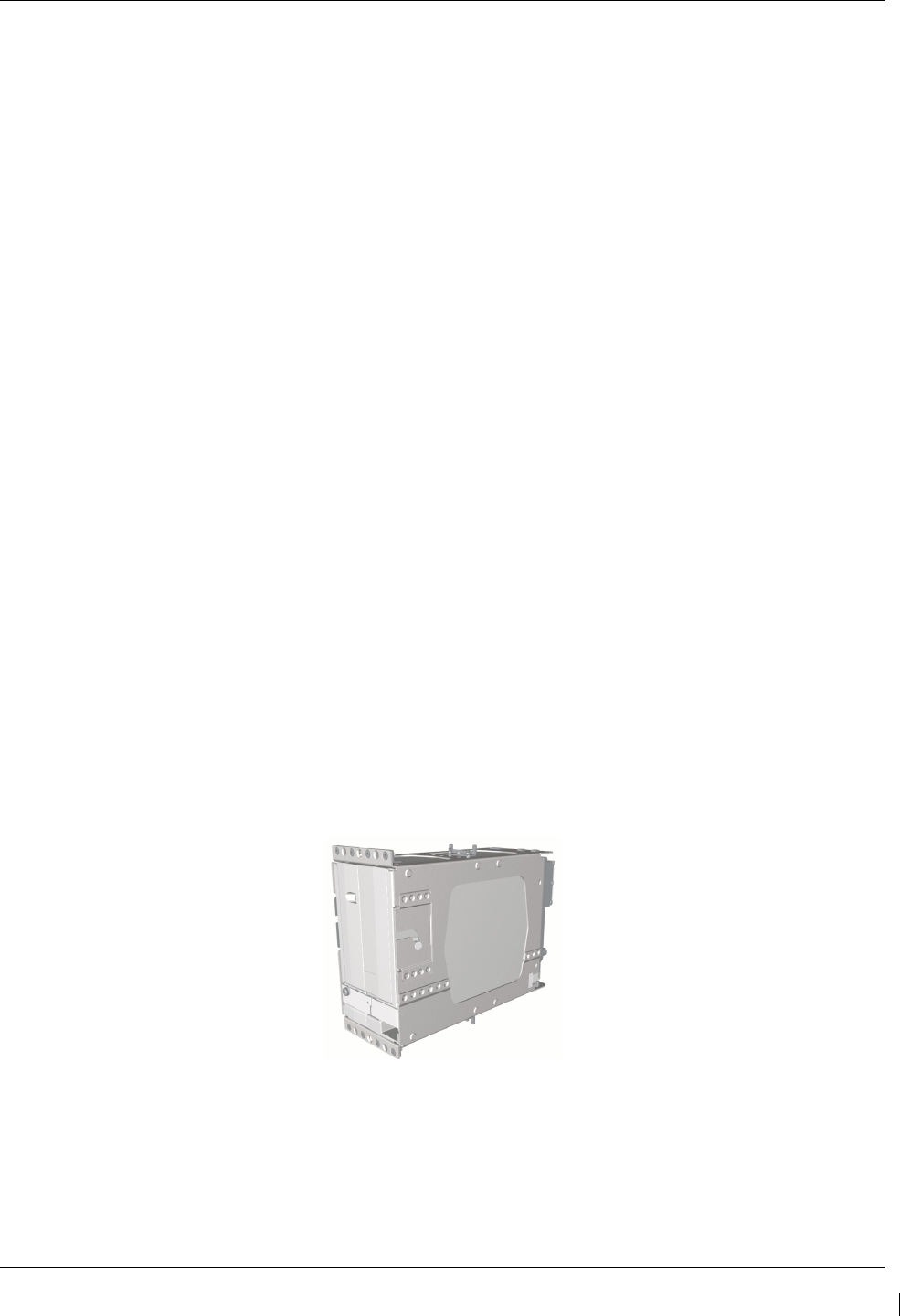
2.1.6 GEA 71 Engine/Airframe Unit (2)
The Garmin GEA 71 Engine/Airframe Units provide engine/airframe data to the G1000 system. Data
received from transducers/sensors is processed and sent to GIA 63Ws (via RS-485 digital interface), and
subsequently to the GDU 1500 MFD. Engine parameters are normally displayed on the MFD. In the event
of MFD failure, the engine parameters can be displayed on PFD 1 and/or PFD 2 using display reversion.
The GEAs are located behind the instrument panel and are mounted in a vertical orientation. Power is
received from the triple-fed bus. Both GEA units will power-up immediately with external or aircraft power
or battery operation.
Each GEA interfaces to the following sensors for its onside engine:
•
Oil Pressure Sensor
•
Oil Temperature Sensor
•
Fuel Flow Sensor (via onside Signal Conditioner)
•
Turbine Speed Sensor (via onside Signal Conditioner)
•
Propeller Speed Sensor(via onside Signal Conditioner)
•
Torque Sensor
•
Interstage Turbine Temperature (ITT) Sensor
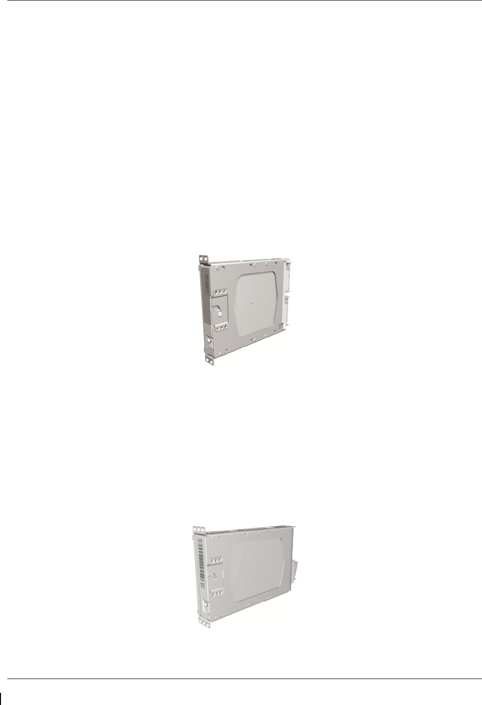
2.1.7 GTX 33 Mode S Transponder (2)
The GTX 33 Non-Extended Squitter or GTX 33 Extended Squitter (ES) (Optional) transponders
communicate with the on-side GIA 63W through RS-232 digital interface. The units are mounted in the
nose equipment bay. Power is provided by the No. 1 and No. 2 avionics bus for GTX 33 No. 1 and No. 2
respectively. The GTX 33 units interface with the existing transponder antennas.
NOTE
A model designation of GTX 33 in this manual will imply either the GTX 33 Non-Extend Squitter or GTX
33 Extended Squitter (ES) transponder.
G1000/GFC700 System Maintenance Manual – C90A/C90GT/C90GTi King Air Page 2-5
190-00682-01 Revision G
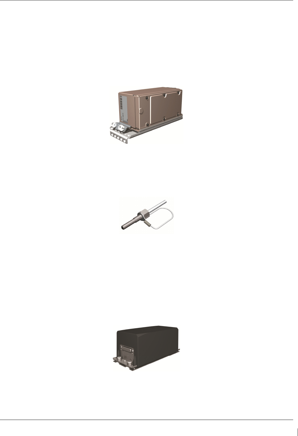
2.1.8 GDC 74B Digital Air Data Computer (2)
The Garmin GDC 74B computers compile information from the pitot/static system and various outside air
temperature (OAT) and awareness sensors and provide digital air data computations to the G1000 system.
The GDC 74B communicates with the GIA 63W, GDU 1040A, and GRS 77 using ARINC 429 digital
interface. The unit is mounted behind the instrument panel. Power is provided to both GDC 74B units by
the triple-fed bus. Additionally, a secondary power source is provided to the No. 1 computer by the center
bus. The GDC 74B connects to existing pitot/static ports via existing tubing in C90A and C90GT airframes.
For C90GTi airframes new pitot/static tubing and hardware is purchased from Hawker Beechcraft Company.
Reference drawing Main Instrument Panel Installation KingAir C90A/C90GT, p/n 005-00375-28 for details.
2.1.9 OAT Probe (2)
The Garmin GTP 59 OAT Probes provide the GDC 74B with air temperature data. The OAT probes are
mounted to the bottom of the King Air fuselage at F.S. 113.5. The probes receive power directly from the
GDC 74B airdata computers.
2.1.10 GRS 77 Attitude & Heading Reference System (2)
The Garmin GRS 77 AHRS units provide attitude and heading information to the G1000 system. The units,
mounted nose equipment bay, contain advanced tilt sensors, accelerometers, and rate sensors. The unit
interfaces with the GDC 74B and GMU44 Magnetometer and utilizes GPS signals from the GIA 63Ws.
Actual attitude and heading information is sent using ARINC 429 digital interface to both GDU 1040As and
GIA 63Ws. Power is provided to both GRS 77 units by the triple-fed bus. Additionally, a secondary power
source is provided to the No. 1 GRS 77 by the center bus. The GRS 77 interfaces with and provides power
to the GMU 44 Magnetometer. The GRS 77 supplies attitude and heading information directly to the PFDs,
MFD, and GIAs.
Page 2-6 G1000/GFC700 System Maintenance Manual – C90A/C90GT/C90GTi King Air
Revision G 190-00682-01
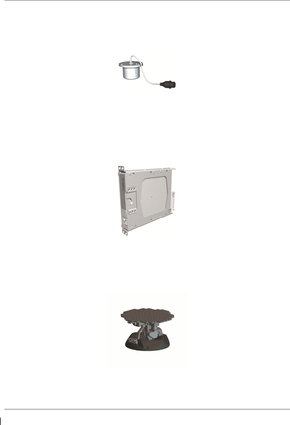
2.1.11 GMU 44 Magnetometer (2)
The GMU 44 provides horizontal and vertical magnetic field information to the GRS 77 AHRS. This allows
heading to be calculated and provides assistance during AHRS alignment. The GMU 44 units are mounted
in the vertical tail. The units receive power directly from the GRS 77 units and communicate with the GRS
77 units via RS-485 digital interface.
2.1.12 GDL 69A Datalink
The GDL 69A provides the interface to the GWX 68 weather radar by acting as a communications hub
between the MFD and GWX68 via HSDB. The GDL 69A also provides XM Radio weather and music
entertainment through means of a dedicated satellite data link. The GDL 69A is mounted behind the
instrument panel. Power to the GDL 69A is received from the avionics No. 3 bus. The GDL 69A sends
weather data through the HSDB bus to the MFD, where the data link interface is controlled. Digital audio is
sent directly to the GMA 1347D Audio Panel.
2.1.13 GWX 68 Weather Radar
The GWX 68 Airborne Weather Radar provides weather radar data output to the GDU 1500 MFD. The
GWX 68 is mounted forward of the forward bulkhead at F.S. 30. Power to the GWX 68 is received from the
avionics No. 2 bus. Data received from the GWX 68 is routed through the GDL 69A data link unit to the
MFD via high-speed data bus (Ethernet).
G1000/GFC700 System Maintenance Manual – C90A/C90GT/C90GTi King Air Page 2-7
190-00682-01 Revision G
2.1.14 GSA 81 Servo, GSA 80 Servo (3) and GSM 85A/86 Servo Mount (4)
The GSA 81 (low-torque) Servo Actuator is an electromechanical unit that will provide automatic control of
pitch trim. The Garmin GSA 80 (high-torque) Servo Actuator is an electromechanical unit that will provide
pitch, roll and yaw damp and turn coordination. The GSA 80/81 contains a motor-control and monitor
circuit board, as well as a solenoid and a brushless DC motor. The GSA 80/81 servo receives serial RS-485
data packets from the GIA 63Ws. The roll servo is located in the lower fuselage at F.S. 185. The pitch, yaw,
and pitch trim servos are located in the tail. Power to the servos is received from the avionics No. 2 bus. All
servos mount to a Garmin GSM 85A (optional GSM 86) Servo Mount. The GSM 85A/86 is responsible for
transferring the output torque of the GSA 80 /81 servo actuators to the mechanical flight control surface
linkage. The GSM 85A has a slip clutch that is field serviceable and can be adjusted to the specified torque
value. The GSM 86 has a clutch cartridge that is not field serviceable, that cannot be adjusted, if the
specified torque value is not within limits the clutch cartridge must be replaced.
2.1.15 Comant CI428-410 / CI428-200 GPS/WAAS Antennas
The Comant CI428-410 GPS/WAAS/XM and CI428-200 GPS/WAAS antennas meet the GPS WAAS
Gamma 3 specifications required for G1000. For procedural instructions on accessing the GPS antennas,
refer to the King Air Model 90 Series Maintenance Manual listed in Table 1-2.
2.1.16 Thommen 5A58.22.26K.28.1 Airspeed Indicator
Either a Thommen 5A58.22.26K.28.1.ET, 5A58.22.26K.28.1.FE, 5A58.22.26K.28.1.FA or
5A58.22.26K.28.1.FP unit is installed as the standby airspeed indicator. The difference between the part
numbers is the location of the Vmca red radial; 80 KT, 85 KT and 90 KT respectively. The General
Arrangement drawing, listed in Table
1-2
, contains Table 4, which shows the applicability of each part
number. The standby airspeed indicator is self illuminated and is connected to the left generator bus. The
internal lights are also connected to the emergency standby battery.
2.1.17 Thommen 3A43.22.35F.28.1.FU Altimeter
The Thommen 3A43.22.35F.28.1.FU altimeter with internal vibrator is used as the standby altimeter. The
vibrator is powered by the No. 1 triple-fed bus. This unit is self illuminated and its internal lighting is
connected to the left generator bus. Both the vibrator and the internal lighting are also connected to the
emergency standby battery.
2.1.18 Mid-Continent 4200-10 Attitude Indicator
The Model 4200-10 Electric Attitude Indicator is used as the standby attitude indicator and is connected to
the No. 3 triple-fed bus. This unit is self illuminated and its internal lighting is connected to the left
generator bus. The unit along with its internal lighting is also connected to the emergency standby battery
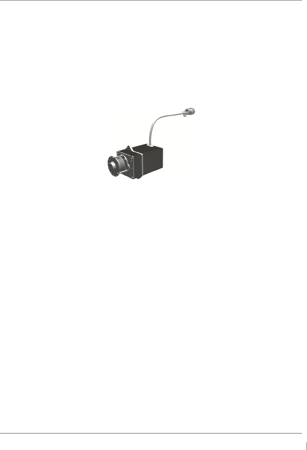
2.1.19 L-3 PS-835(C or D Model) Emergency Standby Battery
In the event of loss of all normal electrical power, the battery is designed to provide 24 Vdc (nominal)
emergency power source for the following items:

Page 2-8 G1000/GFC700 System Maintenance Manual – C90A/C90GT/C90GTi King Air
Revision G 190-00682-01
•
standby attitude indicator (operation and internal lighting)
•
standby altimeter (vibrator and internal lighting)
•
standby airspeed indicator (lighting only)
The aircraft power buss provides a trickle charge to the PS-835 under normal conditions. This battery is
existing in the rear fuselage of aircraft previously equipped with Collins EFIS and is installed in the nose
avionics bay by this STC, on aircraft that were not previously equipped with Collins EFIS.
2.1.20 Engine Signal Conditioning
Changes to the engine signal conditioning components were initiated with STC SA01456WI-D Master
Drawing List (MDL) 005-00375-30, Revision 5. The Sandia ST26 Tach Generator Unit (PN 305662-00),
Senior Aerospace PC920 Signal Conditioning Unit (PN PC920-6A00PH-2A1) and the Garmin 005-00375-
93 Tach-Gen Filter Assembly were replaced by the Vibro-Meter (Meggit) Signal Conditioner Signal
Conditioner. Reference the Main Instrument Panel Installation drawing listed in Table 1-2 for the locations
of the Signal Conditioner Components.
2.1.20.1 Sandia Aerospace ST26 Tach Generator Adapter Units (2)
The ST26 Tach Generator Adapter Units are used for converting the signal from the propeller speed and
turbine speed sensors into a signal that is usable by the GEAs. The output signal from this adapter unit will
be represented by a 5 VDC square wave signal at same frequency of input signal. The No. 1 ST26 (left side)
unit is connected to the No. 1 Triple-fed bus and the No. 2 ST26 (right side) unit is connected to the No. 2
triple-fed bus.
The Sandia Aerospace ST26 Tach Generator Adapter Unit is applicable only to installations using STC
SA01456WI-D Master Drawing List (MDL) 005-00375-30, Revision 4 and previously approved revisions.
2.1.20.2 Senior Aerospace PC920 Signal Conditioning Unit
The PC920 unit was installed per this STC only for aircraft with Senior Aerospace Ketema fuel flow
transducer, part number 1/2-2-81-306. The PC920 unit is used for converting the signal from the fuel flow
sensor into a variable 0 to 5 VDC signal that is proportional to flow rate. The PC920 unit No. 1 channel is
connected to the No. 1 triple-fed bus and the No. 2 channel is connected to the No.2 triple-fed bus. The No.
1 channel (connector P9201) converts the fuel flow signal for the left engine and the No. 2 channel
(connector P9202) converts the fuel flow signal for the right engine.
The Senior Aerospace PC920 Signal Conditioner Unit is applicable only to installations using STC
SA01456WI-D Master Drawing List (MDL) 005-00375-30, Revision 4 and previously approved revisions.
2.1.20.3 Garmin 005-00375-93 Tach-Gen Filter Assembly (2)
The Tach-Gen Filter Assembly is used to filter out high frequency signal noise and is installed between the
Sandia ST26 Signal Conditioner and both the propeller speed and turbine speed sensors. There is one tach-
gen filter installed for each engine. The left engine tach-gen filter is installed on the underside of the floor
panel located forward of the pilots seat position. The right engine tach-gen filter is installed on the underside
of the floor panel located forward of the co-pilots seat position. There are no power requirements for the
tach-gen filter assembly.
The Garmin Tach-Gen Filter Assembly, 005-00375-93 is applicable only to installations using STC SA01456WI-D
Master Drawing List (MDL) 005-00375-30, Revision 4 and previously approved revisions.
2.1.20.4 Vibro-Meter (Meggit) Signal Conditioner (2)
Each GEA 71 receives signals from its on-side engine turbine speed sensor, propeller speed sensor and fuel
flow sensors via a Vibro-Meter (Meggit) Signal Conditioner. This unit converts the signals from the engine

G1000/GFC700 System Maintenance Manual – C90A/C90GT/C90GTi King Air Page 2-9
190-00682-01 Revision G
sensors to a signal usable by the GEA 71. These units are installed behind the instrument panel. Electrical
power to the No. 1 Engine Signal Conditioner is provided from No. 1 Triple-fed bus and to the No. 2 Engine
Signal Conditioner from No. 2 triple-fed bus. Both signal conditioners will power-up immediately with
external or aircraft power or battery operation.
The Vibro-Meter (Meggit) Signal Conditioner is applicable only to installations using STC SA01456WI-D
Master Drawing List (MDL) 005-00375-30, Revision 5 and subsequent approved revisions or fielded
installations modified in accordance with Garmin Document 190-00682-06.
2.2 G1000 Optional Interfaces
Optional equipment includes BF Goodrich WX-500 Stormscope, Traffic System, Rockwell Collins ADF-
60A and Rockwell Collins DME-42. Refer to wiring diagram listed in Table 1-2, for specific interface
information.

Page 2-10 G1000/GFC700 System Maintenance Manual – C90A/C90GT/C90GTi King Air
Revision G 190-00682-01
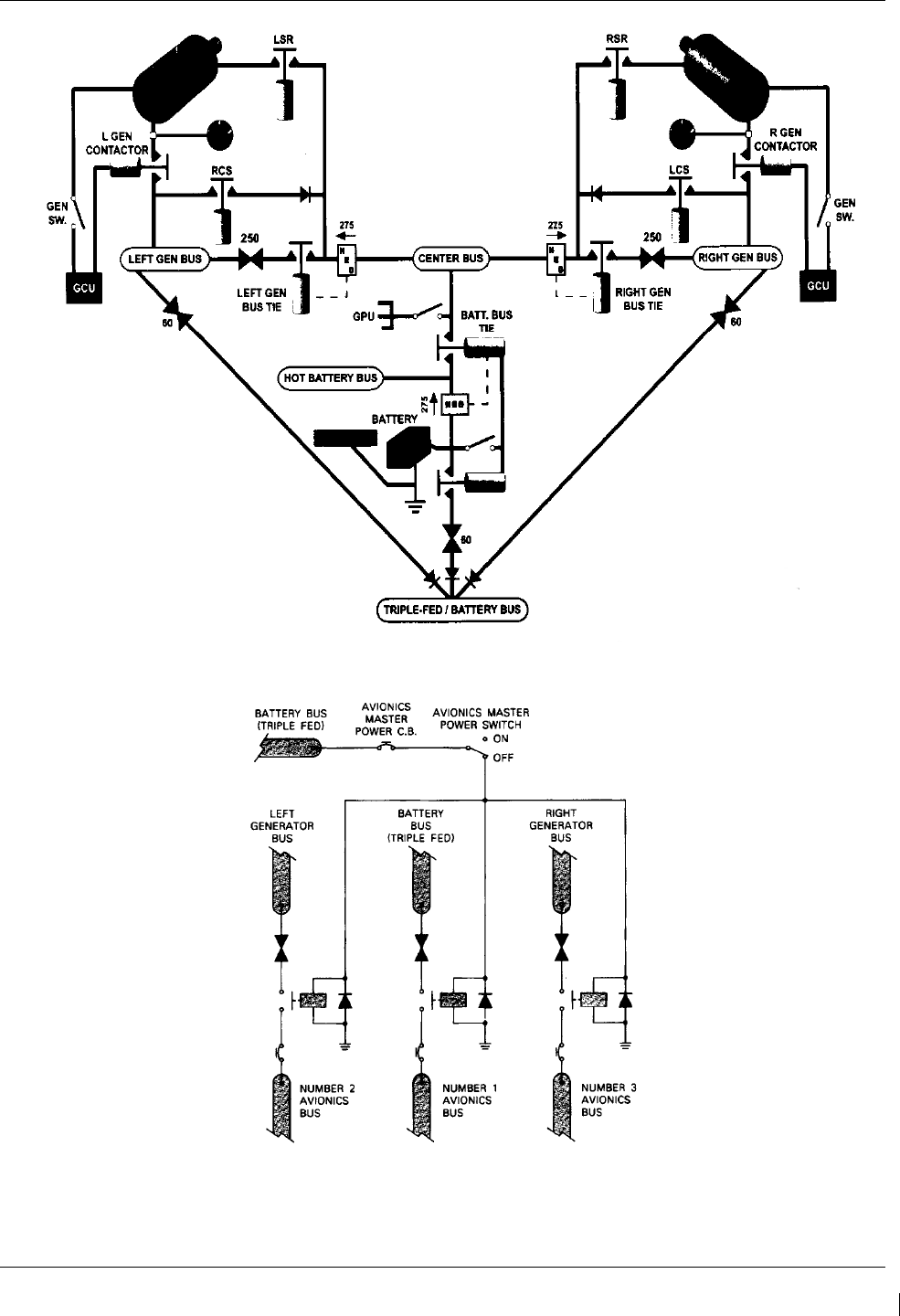
2.3 Electrical Power Distribution
This airplane uses a multi-bus system, as detailed below and in Figures 2-1 and Figure 2-2. In normal
operation, all buses are automatically tied into a single-loop system where all sources supply power through
individual protective devices. The battery and generator switches on the pilot’s left subpanel are used to
control power from the ship battery and generators into the airplane electrical system. Switches in the
cockpit that receive power from the center and triple-fed buses are identified by a white ring on the panel
around the switch.
Left and Right Generator Buses: The left and right generator buses receive power from their respective left
and right generators (ref. Figure 2-1). The left and right generator buses also support the No. 2 and No. 3
avionics buses, respectively, via the avionics master switch (ref. Figure 2-2). The No. 2 avionics bus
supplies power to the following G1000 equipment: GMA 2, GTX 2,), GWX 68, GSA 81 servos. The No. 3
avionics bus supplies power to the GDL 69(). The No. 2 and No. 3 avionics buses also supply power to
optional interface equipment.
Center Bus: The center bus is fed by two generator buses and the hot battery bus, which automatically
connects those components whenever the bus ties are closed (ref. Figure 2-1). The center bus provides a
secondary power source for the following G1000 equipment: PFD 1, GIA 1, GDC 1, and GRS 1.
Triple-fed Bus: The triple-fed is powered from the hot battery bus and both generator buses (ref. Figure 2-1.)
The triple-fed bus also supports avionics no.1 bus via the avionics master switch (ref. Figure 2-2). The
following G1000 equipment is supported by the triple-fed bus: MFD, PFD 1, PFD 2, GCU 475, GMC 710,
GIA 1, GIA 2, GEA 1, GEA 2, GDC 1, GDC 2, OAT, GRS 1, and GRS 2. The No. 1 avionics bus provides
power for the following G1000 equipment: GMA 1 and GTX 1. The No. 1 triple-fed bus provides power to
the No.1 Sandia Aerospace ST26 tach generator adapter, No 1 channel of the Senior Aerospace PC 920 fuel
flow conditioner, No.1 Vibro-Meter (Meggit) Signal Conditioner (if installed), and Thommen standby
altimeter vibrator (under normal conditions.) The No 2 triple-fed bus provides power to the No. 2 Sandia
Aerospace ST26 tach generator adapter, the No. 2 channel of the Senior Aerospace PC 920 fuel flow
conditioner, and the No.2 Vibro-Meter (Meggit) Signal Conditioner (if installed). The No. 3 triple-fed bus
provides power to the Mid-Continent standby attitude indicator (under normal conditions) and provides
power for charging the L-3 emergency standby battery.
Emergency Standby Battery Function: The Standby Emergency Battery (STBY BATT) system in the King
Air C90 is designed to provide uninterrupted DC power to the Standby Attitude indicator (gyro motor) and
the Standby Altimeter (vibrator) from the L-3 PS-835(C or D Model) Emergency Standby Battery. In
addition, the STBY BATT system supplies a fixed lighting voltage to the Standby Attitude Indicator, the
Standby Altimeter, and the Standby Airspeed Indicator in the event of a total loss of DC power (ref. Figure
2-1.) For aircraft retrofitted using STC SA01456WI-D Master Drawing List (MDL) 005-00375-30, Revision
6 or later, the STBY “whiskey” compass will also receive lighting from the STBY BATT in the event of a
total loss of DC power. The STBY BATT system is a redundant power source to the Standby Attitude
indicator, Standby Altimeter, and the Standby Airspeed Indicator.
The electrical system is protected from excessively high current flow by the bus tie system. A bus tie sensor
and relay is located between each generator bus and the center bus and also between the battery bus and the
center bus. When the battery switch is on, battery bus voltage energizes and closes the relay. Similarly,
when a generator or external power is brought on-line, the generator bus tie relays are energized and closed.
G1000/GFC700 System Maintenance Manual – C90A/C90GT/C90GTi King Air Page 2-11
190-00682-01 Revision G
Figure 2-1. C90 Electrical Distribution
Figure 2-2. Avionics Master Power Schematic
Page 2-12 G1000/GFC700 System Maintenance Manual – C90A/C90GT/C90GTi King Air
Revision G 190-00682-01
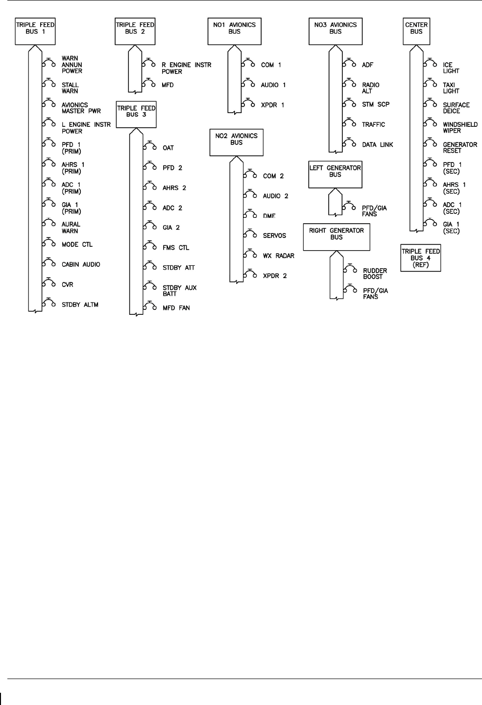
Figure 2-3. G1000 Component Power Sources
2.4 Shield Block Grounds
The connectors on Garmin G1000 LRUs utilize the Shield Block grounding system to provide necessary
ground reference to wire shielding and/or transducers. The shield block termination method allows multiple
grounds to be terminated directly to a block mounted to the connector backshell assembly. Shielding and
grounding requirements for all other LRUs and connectors are shown in the respective install drawings.
G1000/GFC700 System Maintenance Manual – C90A/C90GT/C90GTi King Air Page 2-13
190-00682-01 Revision G
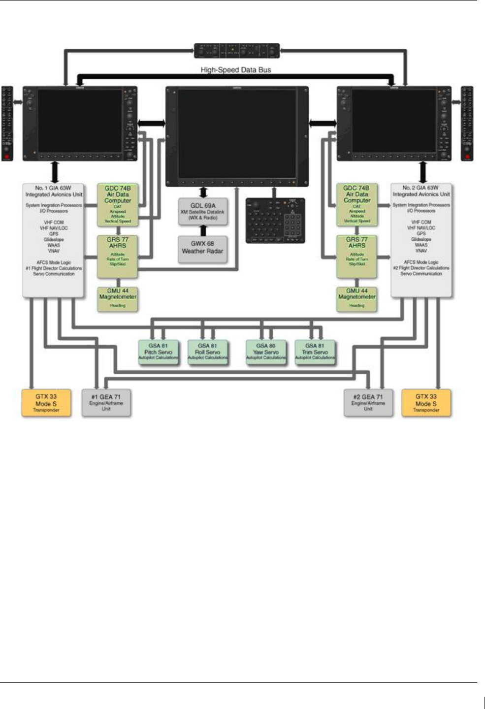
2.5 G1000 /GFC700 Block Diagram
Figure 2-4. G1000/GFC 700 Block Diagram

Page 2-14 G1000/GFC700 System Maintenance Manual – C90A/C90GT/C90GTi King Air
Revision G 190-00682-01
This page intentionally left blank
G1000/GFC700 System Maintenance Manual – C90A/C90GT/C90GTi King Air Page 3-1
190-00682-01 Revision G
3 G1000 Control & Operation
All control and operation of G1000 equipment as normally used in flight occurs through the PFDs, MFD,
GMC 710, GCU 475 and GMA 1347D audio panel. Figure 3-1 thru Figure 3-6 identifies various
interface buttons for these units.
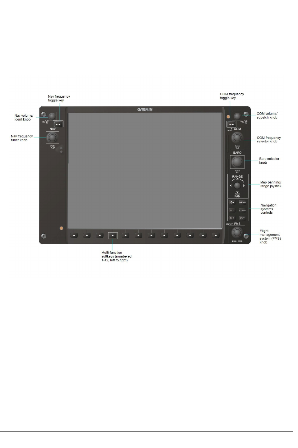
3.1 GDU 1040A and GDU 1500 Displays
Figure 3-1 and Figure 3-2 provide identification of the GDU 1040A PFD and GDU 1500 MFD controls.
Figure 3-1. GDU 1040A Control Interface
Page 3-2 G1000/GFC700 System Maintenance Manual – C90A/C90GT/C90GTi King Air
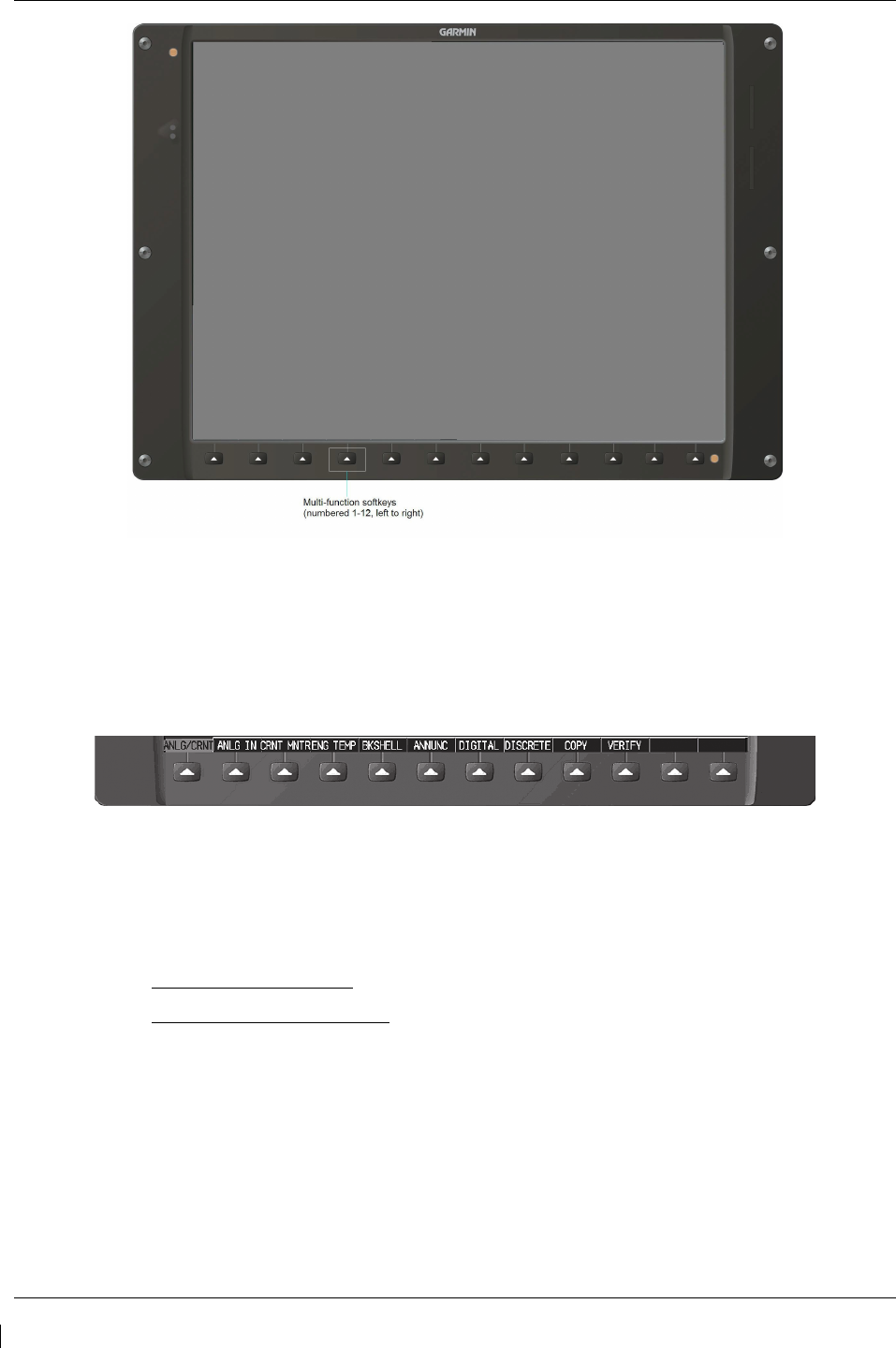
Revision G 190-00682-01
Figure 3-2. GDU 1500 Control Interface
3.1.1 Softkeys
Some pages have commands or selections that are activated by the GDU 1040 softkeys. If a softkey is
associated with a command, that command will be displayed directly above the key. A grayed-out
softkey shows a command that is unavailable. A softkey that is highlighted shows the current active
selection.
Figure 3-3. G1000 Softkeys
3.1.2 FMS Knob
The FMS knob shown in Figure 3-1 and Figure 3-4is the primary control for the G1000 system.
•
To cycle through different configuration screens:
To change page groups: Rotate the large FMS knob.
To change pages in a group: Rotate the small FMS knob.
•
To activate the cursor for a page, press the small FMS knob directly in, as one would push a
regular button.
•
To cycle the cursor through different data fields, rotate the large FMS knob.
•
To change the contents of a highlighted data field, rotate the small FMS knob. This action either
brings up an options menu for the particular field, or in some cases allows the operator to enter
data for the field.
•
To confirm a selection, press the ENT key.
•
To cancel a selection, press the small FMS knob in again, deactivating the cursor. The CLR key
may also be used to cancel a selection or deactivate the cursor.
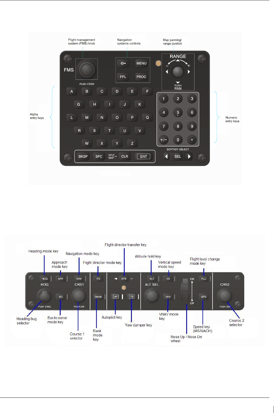
G1000/GFC700 System Maintenance Manual – C90A/C90GT/C90GTi King Air Page 3-3
190-00682-01 Revision G
3.2 GCU 475 - MFD Controller
The MFD controls are located on the GCU 475 as show in Figure 3-4.
Figure 3-4. MFD Controls (GCU 475)
3.3 GMC 710 - AFCS Controls
The dedicated AFCS controls located on the GMC 710 are discussed in detail in the G1000 CRG. The
following figure is provided for reference:
Figure 3-5. AFCS Controls (GMC 710)
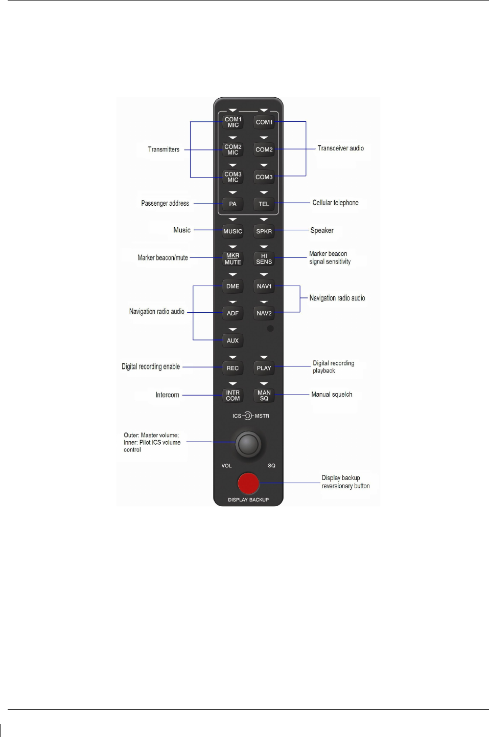
Page 3-4 G1000/GFC700 System Maintenance Manual – C90A/C90GT/C90GTi King Air
Revision G 190-00682-01
3.4 GMA 1347D Audio Panel
Figure 3-6 provides the audio panel controls for GMA 1347D PN 011-01257-00. The GMA 1347D PN
011-01257-00 is applicable only to installations using STC SA01456WI-D Master Drawing List (MDL)
005-00375-30, Revision 4 and previously approved revisions.
Figure 3-6. GMA 1347D PN 011-01257-00 Controls
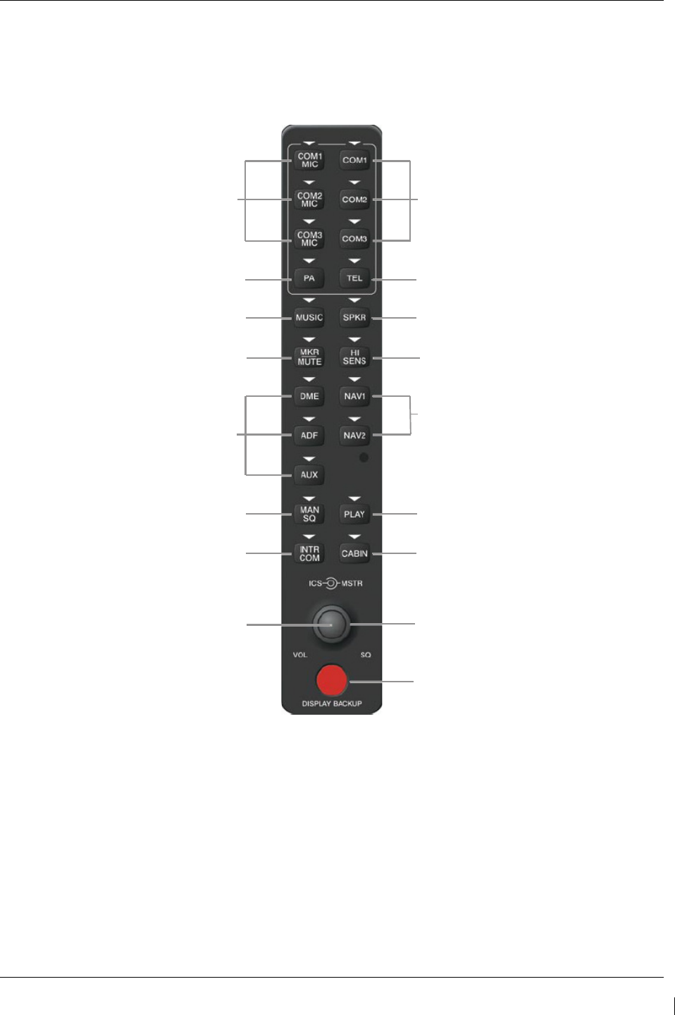
G1000/GFC700 System Maintenance Manual – C90A/C90GT/C90GTi King Air Page 3-5
190-00682-01 Revision G
Figure 3-7.
GMA 1347D PN 011-01257-20 Controls
provides the audio panel controls for GMA 1347D PN
011-01257-20. The GMA 1347D PN 011-01257-20 with the Cabin Intercom button is applicable only to
installations using STC SA01456WI-D Master Drawing List (MDL) 005-00375-30, Revision 5 and
subsequent approved revisions or fielded installations modified in accordance with Garmin Document
190-00682-06.
Transceiver Audio
Telephone
Speaker
Marker Beacon Signal
Sensitivity
Transceiver Audio
Passenger Address
Music
Marker Beacon Mute
Transmitters
Digital Recording Playback
Cabin Intercom
Master VOL (Large Knob)
Reversionary Mode
Aircraft Navigation
Radio Audio
Manual Squelch
Intercom System (ICS)
ICS VOL SQ (Small Knob)
Figure 3-7. GMA 1347D PN 011-01257-20 Controls
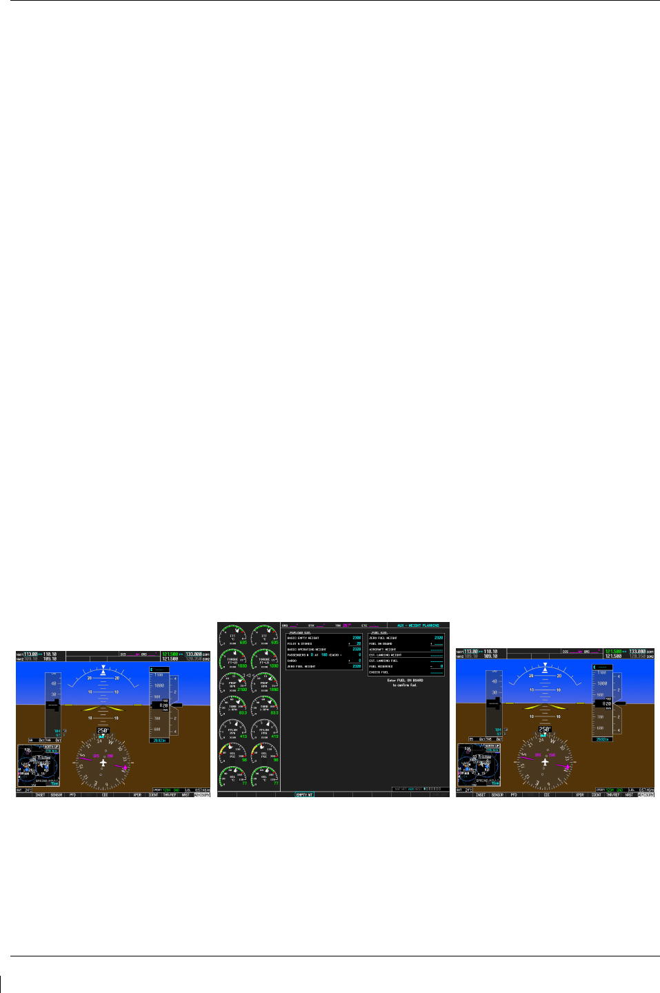
Page 3-6 G1000/GFC700 System Maintenance Manual – C90A/C90GT/C90GTi King Air
Revision G 190-00682-01
3.5 G1000 Normal Mode
To start the G1000 system in Normal Mode:
1. With a ground power unit connected to the external power receptacle, set the BAT and EXT
PWR switches to ‘ON’. The following G1000 equipment is powered:
•
PFDs displays & MFD display
•
GRS 77 AHRS Units
•
GDC 74B Air Data Computers
•
GIA 63W Integrated Avionics Units
•
GEA 71 Engine/Airframe Units
•
GCU 475 FMS Control Unit
•
GMC 710 Autopilot Control Unit
2. Set the AVIONICS MASTER PWR switch to ‘ON’. The following G1000 equipment is
powered:
•
GTX 33 Mode S Transponders
•
GMA 1347D Digital Audio Panels
•
GDL 69A Datalink Unit
•
GSA Servos
•
GWX 68 Weather Radar Unit
The G1000 system is now powered in the normal mode. In the normal operating mode, data fields that
are invalid have large red X’s through them. A valid field does not display a red X. Allow the displays to
initialize for approximately one minute. The GDC 74Bs requires a longer initialization period than do the
other LRUs. During normal operation, this causes the airspeed, altitude, vertical speed, and OAT fields to
be invalid during the first ~40-60 seconds of PFD power-up
.
The PFDs and MFD will function as
specified in the G1000 C90A/C90GT/C90GTi Cockpit Reference Guide, when the system has been
correctly installed and configured.
Figure 3-8. Normal Mode
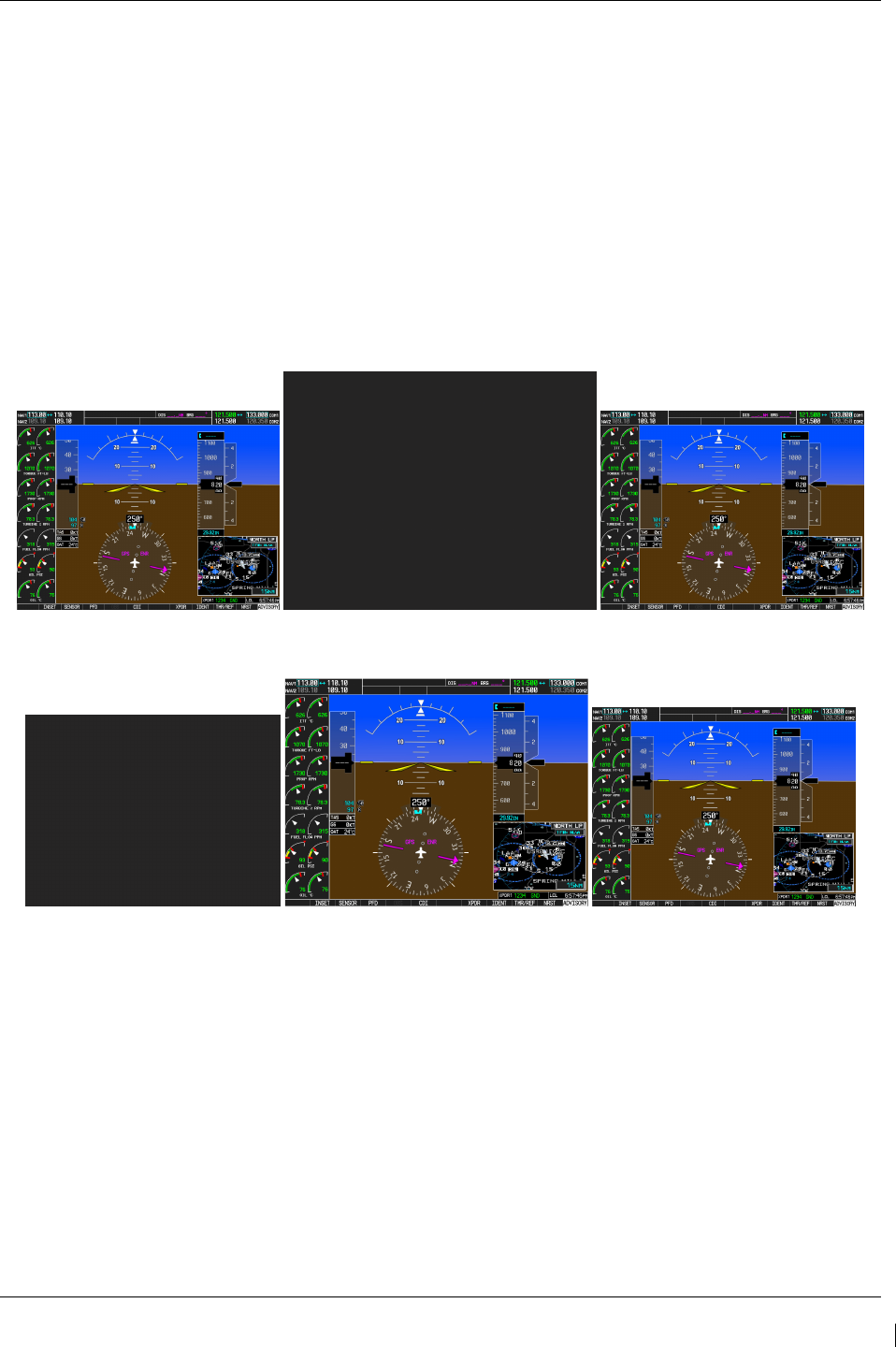
G1000/GFC700 System Maintenance Manual – C90A/C90GT/C90GTi King Air Page 3-7
190-00682-01 Revision G
3.6 Reversionary Mode
Reversionary mode allows for display of information related to safe flight in the event of a display
communication or hardware failure. On this 3-display system, only a manual reversionary mode is
possible. Manual reversionary mode allows the operator to force the pilot or copilot’s PFD into
reversionary mode by pressing the large red button labeled ‘DISPLAY BACKUP’ on the respective
GMA 1347 audio panel.
NOTE
When the ‘DISPLAY BACKUP’ button is pushed to exit reversionary mode, there is a 5-second
debounce (or the GDU waits for 5 consecutive seconds) and then returns to normal mode if no other input
is received. If the ‘DISPLAY BACKUP’ button is pushed again during this 5-second interval, the timer
will repeat the count.
Figure 3-9. Manual Reversion with MFD failure
Figure 3-10. Manual Reversion with pilot PFD failure

Page 3-8 G1000/GFC700 System Maintenance Manual – C90A/C90GT/C90GTi King Air
Revision G 190-00682-01
3.7 Configuration Mode Overview
The Configuration Mode exists to provide the avionics technician with a means of configuring, checking,
and calibrating various G1000 sub-systems. Troubleshooting and diagnostics information can also be
viewed in this mode.
To start the system in Configuration Mode:
1. Apply external power, then set the BAT, EXT PWR and AVIONICS MASTER PWR switches to
ON.
2. Pull the MFD, PFD1 (PRI), PFD1 (SEC) and PFD2 circuit breakers.
3. Press and hold the ENT key on the co-pilot’s PFD while applying power using the PFD 2 circuit
breaker.
4. Release the ENT key after ‘INITIALIZING SYSTEM’ appears in the upper left corner of the
PFD.
5. Press the ENT key or the YES softkey to update system files if prompted.
6. Repeat steps 1 through 3 on the MFD using the MFD circuit breaker to apply power and using the
far right soft key on the MFD or the ENT key on the GCU 475 FMS controller where called out
in Steps 1 through 3. (Note that the ENT key for the MFD is located on the GCU 475 FMS
controller and will not function prior to software load.)
7. Repeat steps 1 through 3 on the pilot’s PFD using the PFD 1 (PRI) and PFD 1 (SEC) circuit
breakers to apply power.
CAUTION:
The Configuration Mode contains certain pages and settings that are critical to aircraft
operation and safety. These pages are protected and cannot be modified, unless the
technician is properly authorized and equipped. However, most protected pages are
viewable to allow system awareness for troubleshooting.
NOTE
If the specific procedure requires an SD card to be in the top slot of the PFD/MFD, this
card must be inserted prior to applying power to the PFD/MFD. Any time a card is
inserted, the power to the PFD/MFD must be cycled.
NOTE
For a complete description and breakdown of each Configuration Mode page, refer to the
G1000 System Maintenance Manual listed in Table 1-2.
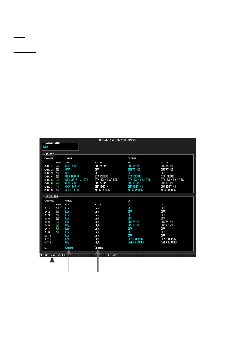
G1000/GFC700 System Maintenance Manual – C90A/C90GT/C90GTi King Air Page 3-9
190-00682-01 Revision G
3.7.1 SET>ACTV Configuration
Throughout the configuration mode pages, there are SET and ACTIVE columns for input/output settings
and other parameters.
SET: Refers to a setting or group of settings that reside in PFD Internal Memory and/or the
Master Configuration Module.
ACTIVE: Refers to an ‘active’ setting or parameter currently being used by the LRU. LRUs store
the ‘active’ settings within internal memory.
Data can be manually copied from one column to the other (and consequently from PFD memory to the
LRU memory and vice-versa) by using the following two softkeys, when available:
•
SET>ACTV (read ‘Set to Active’) softkey: Allows the installer to send the information in the SET
column (data stored in the master config module) to the ACTV column (data used by LRU).
•
ACTV>SET (read ‘Active to Set’) softkey: Causes the LRUs current settings to be copied to the
master configuration module as SET items.
CAUTION:
The ACTV>SET softkey must be used with caution! If an improperly configured unit is
installed, this softkey causes the wrong configuration to replace the correct aircraft
configuration.
SET>ACTV and ACTV>SET Softkeys
SET Column ACTIVE Column
Figure 3-11. SET and ACTV Softkeys and Columns
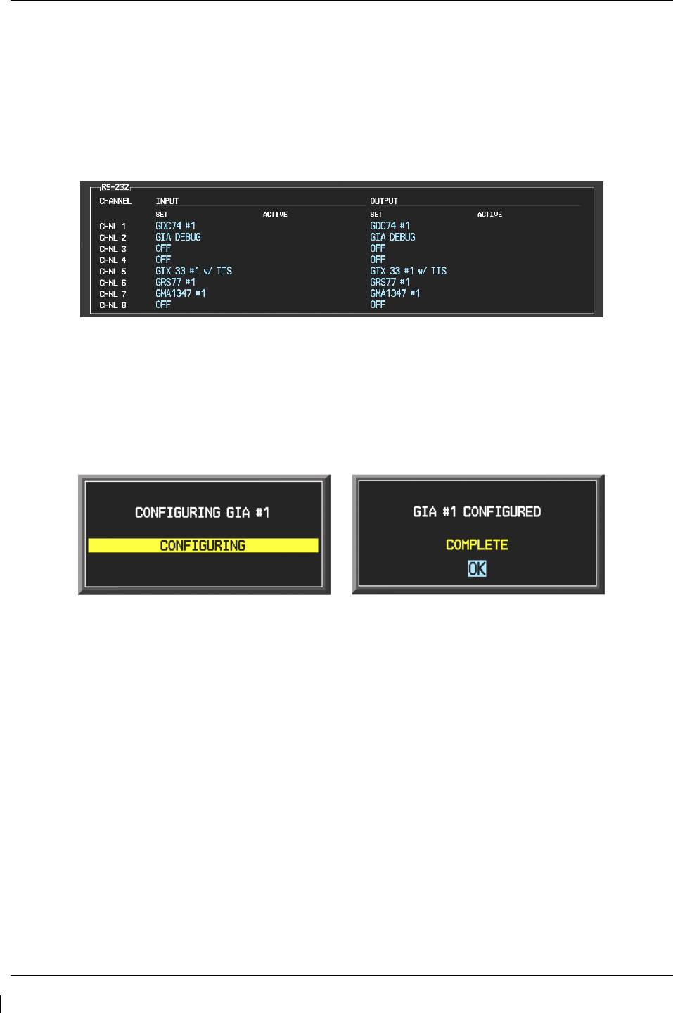
Page 3-10 G1000/GFC700 System Maintenance Manual – C90A/C90GT/C90GTi King Air
Revision G 190-00682-01
When troubleshooting the system, technicians can look for inequalities between SET and ACTIVE
columns. Certain problems can be resolved simply by pressing the SET>ACTV softkey, which reloads
settings to the specific LRU from the PFD. (Note that this can also be accomplished by reloading the
configuration files for the LRU, using the software loader card. Section 7 describes this process for each
LRU).
A blank active column, as shown in Figure 3-12, represents loss of communication between the display
and the particular unit. See Section 5 for more details on troubleshooting.
Figure 3-12. Loss of Communication
3.7.2 Configuration Prompts
When configuration settings are changed, the technician receives on-screen prompts and/or confirmations
such as those shown in Figure 3-13. Section 7 shows other prompts encountered during the configuration
process.
Figure 3-13. Configuration Status
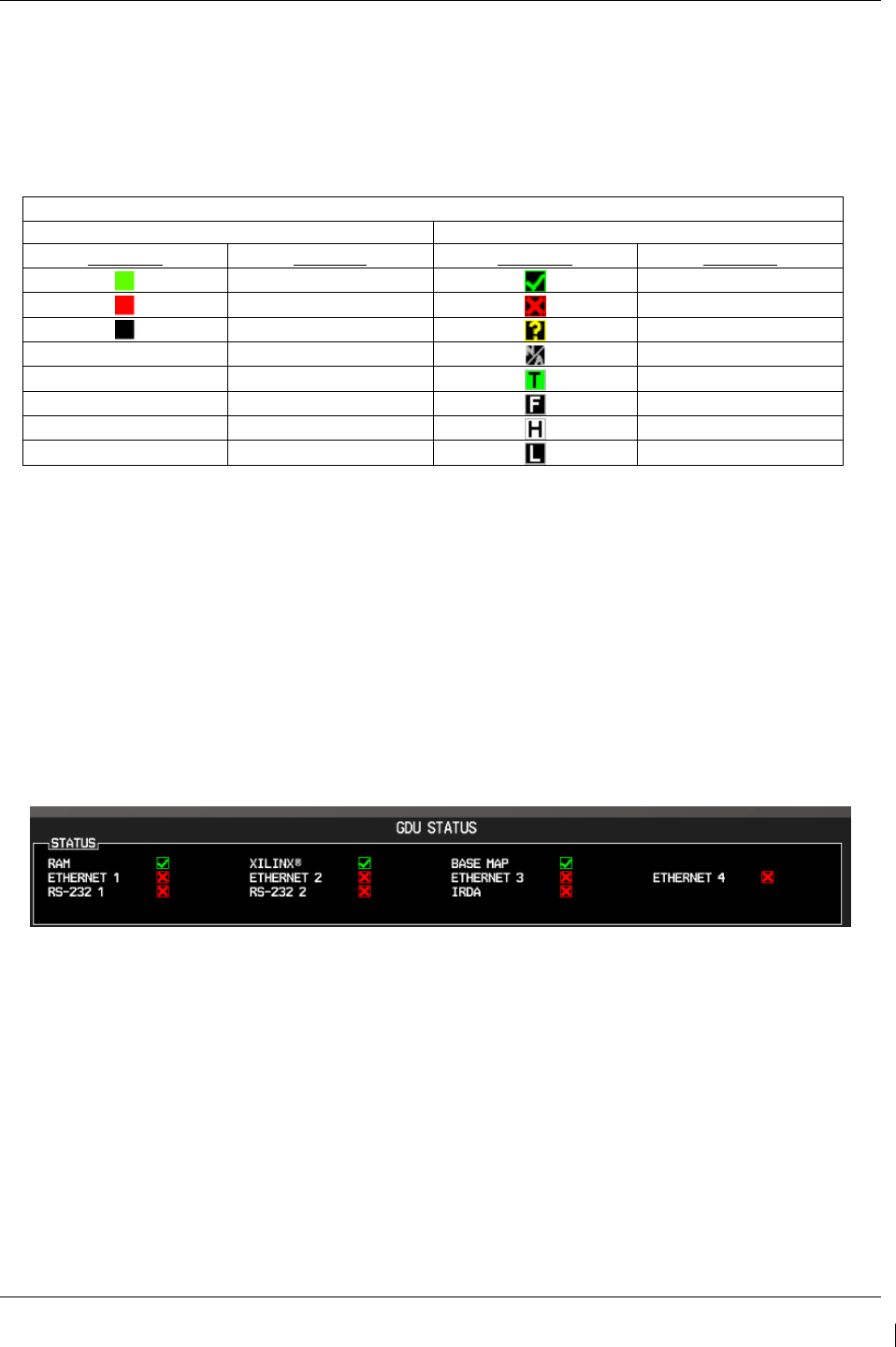
G1000/GFC700 System Maintenance Manual – C90A/C90GT/C90GTi King Air Page 3-11
190-00682-01 Revision G
3.7.3 Data Transmission Indicators
Several configuration screens utilize an indicator light system to show discrete (ON/OFF) data and/or
hardware component status. A difference in the presentation of the data indicator exists between the two
approved versions of C90A G1000 system software. Table 3-1 presents the data indicator differences
between the two versions of software.
Table 3-1. Data Indicator Symbols
This manual will depict the data indicator symbols used by the C90A G1000 System Software PN 006-
B0636-03, Version 0636.03. The following applies to all such status indicators:
• Green Checkmark: Expected data is successfully received and is ON or VALID. A green check
could also indicate that the parameter/component is working correctly.
• Red X: Expected data is not received. A red X could also indicate that a parameter/component is
INVALID or FAIL.
• Amber question mark (?): Data is unknown.
• White N/A: Expected data is OFF, or no data is expected.
Figure 3-14. Data Transmission Indicators
G1000 System Software Data Indicator Symbol Differences
006-B0636-01, v 0636.01 006-B0636-02, v 0636.02
Indicator Meaning Indicator Meaning
Valid
Valid
Invalid/Fail
Invalid/Fail
Unknown
Unknown
- -
OFF
- -
TRUE
- -
FALSE
- -
HIGH
- -
LOW

Page 3-12 G1000/GFC700 System Maintenance Manual – C90A/C90GT/C90GTi King Air
Revision G 190-00682-01
3.7.4 Configuration Mode Navigation
Using the FMS knob as described in Section 3.1.2, a user can navigate through different pages and page
groups in the Configuration Mode. For complete description and breakdown of each page, refer to the
G1000 System Maintenance Manual listed in Table 1-2.
System Page Group
1. System Status 6. Diagnostics Terminal 11. Manifest Configuration
2. Time Configuration 7. OEM Diagnostics 12. Maintenance Log
3. Lighting Configuration 8 System Configuration
4. System Audio 9. System Data Path Configuration
5. System Upload 10. System Setup
GDU Page Group
1. Serial Configuration 4. Diagnostics 7. Alert Configuration
2. CDU Status Page 5. Ethernet Test 8. Airframe Configuration
3. Key Test 6. Video Test 9. TAWS Configuration
GIA Page Group
1. Serial Configuration 3. GIA I/O Configuration 5. GIA Status Page
2. GIA / RS-485 Configuration 4. GIA Configuration 6. GIA CAN Configuration
GEA Page Group
1. Engine Configuration 2. GEA Status Page 3. GEA Configuration
GTX Page Group
1. Serial Configuration 2. Transponder Configuration
GRS Page Group
1. Inputs Configuration 2. GRS / GMU Calibration
ADC Page Group
1. ADC Configuration 2. GDC Configuration
GFC Page Group
1. GFC Configuration 2. GFC Status
GMA Page Group
1. GMA Configuration
GDL Page Group
1. GDL 69
RMT Page Group
1. Remote Controller Status
GWX Page Group
1. GWX Configuration
CAL Page Group
1. Fuel Tank Calibration 2. Flaps & Trim Calibration 3. HSCM Calibration

G1000/GFC700 System Maintenance Manual – C90A/C90GT/C90GTi King Air Page 3-13
190-00682-01 Revision G
3.8 G1000 / GFC 700 Software Information
NOTE
The following sections provide a detailed description of loading all G1000 software and
configuration files. Loading of all software and configuration files is usually not required
for removal and replacement of units. Refer to Section 6 of this manual for the necessary
steps during removal and replacement of G1000/GFC 700 equipment.
3.8.1 G1000 Software Image
All software and configuration files were certified by Garmin and are considered part of FAA-approved
Type Design data. Approved software and hardware definitions for each STC Configuration is defined on
the appropriate General Arrangement drawing listed in Table 1-2.
G1000 software and configuration files are controlled via the approved software image part number listed
on the General Arrangement drawing listed in Table 1-2. This software image is loaded into the G1000
using a software loader card. The installer shall create this software loader card by downloading the
approved software image in accordance with section 3.8.2.
NOTE
Only SanDisk and Toshiba brand 2GB SD cards are recommended for use with the
G1000 system.
NOTE
Installers may obtain this software image already on a loader card by ordering Garmin
Part number 010-00640-XX directly from Garmin. Reference the General Arrangement
drawing listed in Table 1-2 for part number information.
IMPORTANT!
To satisfy the G1000/GFC700 STC requirements for the C90A/C90GT/C90GTi, it is
critical that the technician use the correct software loader card part number when
servicing the G1000 system.
Approved loader card part numbers are defined on the appropriate General
Arrangement drawing (see Table 1-2).
CAUTION:
Be cautious when using software loader cards during maintenance. The G1000 system
immediately initializes the card upon power-up. On-screen prompts must be given
careful attention in order to avoid potential loss of data. Always read through procedures
given in Sections 5, 6, and 7, before attempting to use the software loader cards.
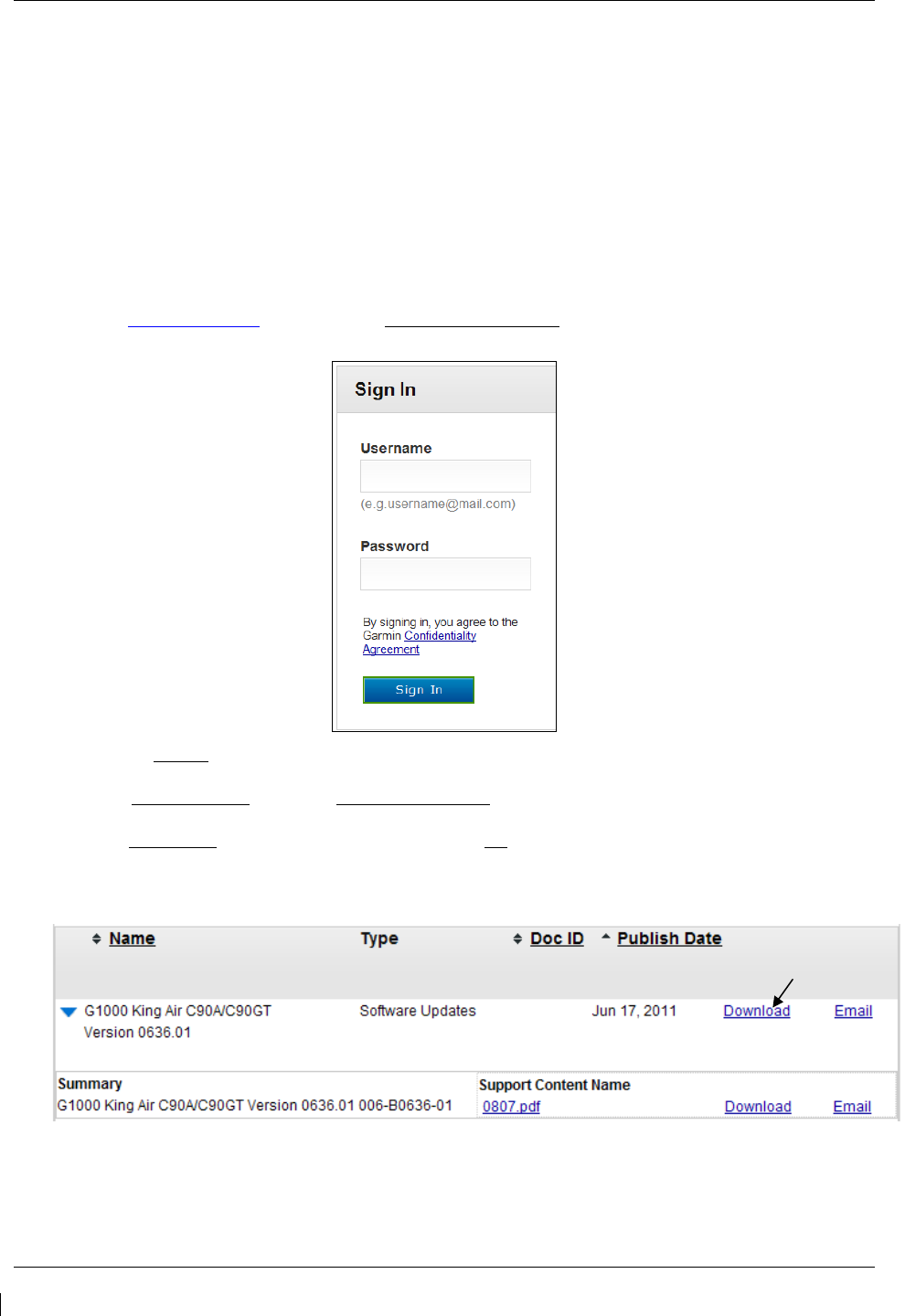
Page 3-14 G1000/GFC700 System Maintenance Manual – C90A/C90GT/C90GTi King Air
Revision G 190-00682-01
3.8.2 Loader Card Creation
The software image is an executable self-extracting file which builds the correct file structure onto an SD
card for use loading software to the G1000 and GFC700. To create a software loader card, follow the
procedures outlined below.
NOTE
In order to create a C90A/GT/GTi loader card, the individual/facility completing these
procedures, must be an authorized King Air C90 service center to gain access to the
necessary data via the Garmin website.
1. Go to www.garmin.com and click on the Dealer Resource Center link in the lower portion of the home
page. Enter username and password.
2. Click the I Agree button on the confidentiality agreement page.
3. Select Technical Tools then select Software Downloads.
4. In the Keyword(s) filter, enter “0636” and click on the Go button.
5. A screen similar to the one shown below will appear. The numbers shown are for example only.
(example figure)
6. Click on the download symbol for the appropriate software version part number based upon the information
provided in Garmin GA Drawing 005-00375-22 and save the file to the local hard drive.
Download
link
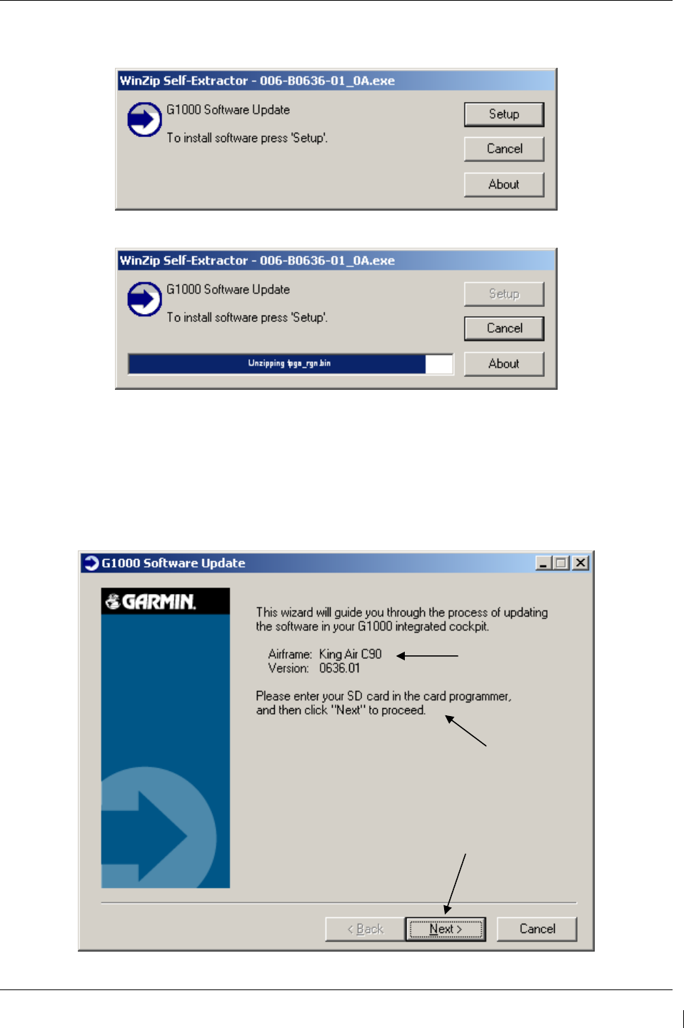
G1000/GFC700 System Maintenance Manual – C90A/C90GT/C90GTi King Air Page 3-15
190-00682-01 Revision G
7. Double-click the .exe file that was downloaded. The following window will pop-up on the screen. Ensure
that there is an empty SD card in the card reader, and then click Setup.
(example figure)
(example figure)
NOTE
When the extraction begins, the program automatically deletes all current files on the SD
card and copies the selected files to it, regardless of the file format on the SD card.
Ensure files are not necessary, or card is empty before proceeding.
(example figure)
Version of card
being created
Enter SD card
Click next once
card is inserted
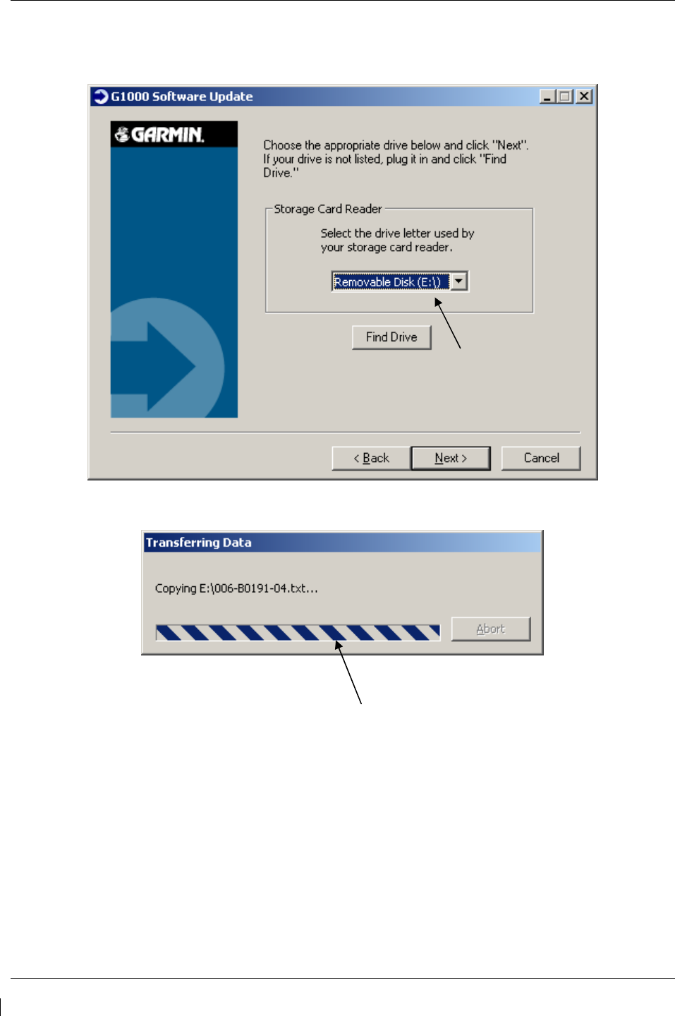
Page 3-16 G1000/GFC700 System Maintenance Manual – C90A/C90GT/C90GTi King Air
Revision G 190-00682-01
8. Ensure the card and correct drive letter is used, and click next.
9. A window will pop-up onto the screen to indicate file progress.
Select drive
Copy of files to
selected drive
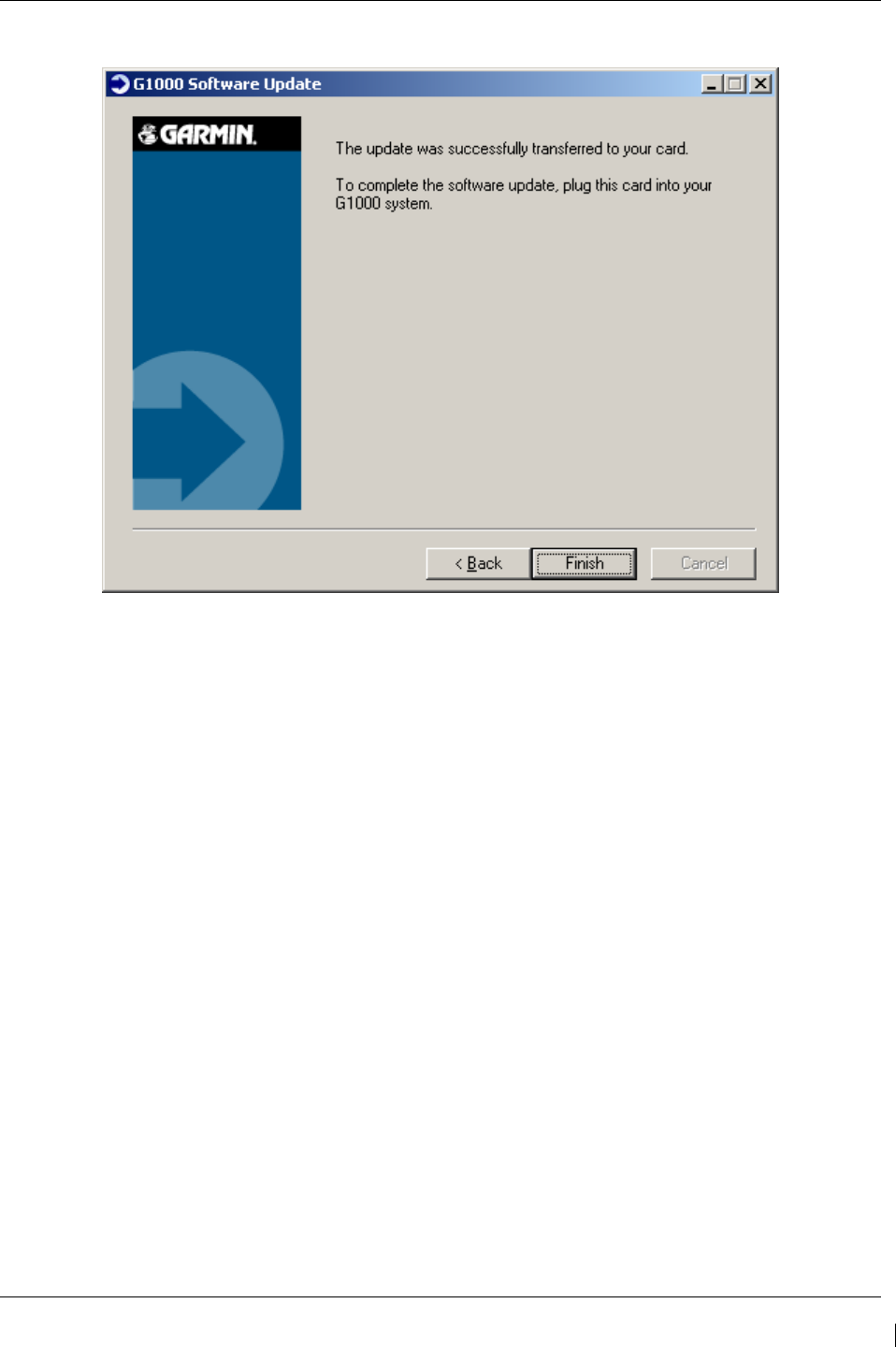
G1000/GFC700 System Maintenance Manual – C90A/C90GT/C90GTi King Air Page 3-17
190-00682-01 Revision G
10. Once successfully completed, the following message/window will pop-up. Click Finish to finalize SD card.
3.8.3 Software Files
Software files are defined by part number and version number on the General Arrangement drawing. See
Table 1-2 for the correct General Arrangement drawing part numbers. Each G1000 / GFC 700 LRU
reports the software version it currently contains to the user in two places.
• Normal System Mode: The AUX – SYSTEM STATUS page lists each LRU and the reported
software version.
• Configuration Mode: The SYSTEM STATUS page (SYSTEM page group) reports more detailed
LRU information, including software version, part number, and LRU status.
Software files are loaded to LRUs from the SYSTEM UPLOAD page in configuration mode. See Section
3.9.2.

Page 3-18 G1000/GFC700 System Maintenance Manual – C90A/C90GT/C90GTi King Air
Revision G 190-00682-01
3.8.4 Configuration File Descriptions
Configuration Files are divided into groups, and are only displayed at the System Upload page during the
software/configuration loading process. There are five categories of configuration files:
C90
C90-Options
C90-Configurations
C90-Configurations 2
C90-Weight and Airspeed
Configuration files contain preset selections for input/output channels, aircraft-specific settings, and
LRU-specific settings. The following list describes each of the configuration files:
AIRFRAME This file contains data such as airspeed parameters, engine/airframe sensor
limitations, fuel tank parameters and alerting system settings that tailor a
G1000 PFD or MFD to the C90A/GT/GTi.
AIRFRAME C90A/GT/GTi-specifc alerts are set when this file is loaded.
ALERTS
SYSTEM This file configures the G1000 high-speed data bus (HSDB) to expect two
PFDs, MFD, two GIAs, and a GDL69.
MANIFEST This file loads a manifest checklist of all software part numbers and versions
associated with an approved system configuration. The G1000 performs a
software check between each LRU’s reported version and the version
contained on the manifest. If an inequality is detected for an LRU, this LRU is
then excluded from the G1000 and a manifest alert is triggered to the operator.
MFD1 This file configures MFD serial/discrete communication and alert system
settings.
PFD 1/PFD 2 These files configure PFD 1/PFD 2 serial/discrete communication and alert
system settings.
GCU This file configures GCU 475 serial/discrete communication settings.
GMC This file configures GMC 710 serial/discrete communication settings.
GIA1/GIA2 These files configure GIA1/GIA2 serial/discrete communication settings.
GMA_PIL/ This file configures GMA 1347 audio and serial communication settings
GMA_COPIL for both audio panels.
GTX1/GTX2 These files configure GTX 1/GTX 2 transponder and serial communications
settings.
GEA1/GEA2 These files configure GEA 1/GEA 2 engine/airframe parameters.
GDC_PIL/ This file configures GDC 74B air data values for the C90A/GT/GTi.
GDC_COPIL
GDL_69 This file configures gains and cable loss for the C90A/GT/GTi installation.
GWX This file configures parameters as appropriate for the C90A/GT/GTi radar
installation.
AUDIO This file configures audio alerts for the C90A/GT/GTi.

G1000/GFC700 System Maintenance Manual – C90A/C90GT/C90GTi King Air Page 3-19
190-00682-01 Revision G
3.8.4.1 Airframe and Optional Configurations
Optional equipment configurations are available with the C90A/GT/GTi. These files are loaded after the
factory default configuration is established. Each option modifies one or more of the above configuration
files, depending on what setting changes are required to activate the optional equipment. It should be
noted that any required supporting hardware for the option must be installed before the option can
function.
The following default configuration appears at the System Upload page within the FILE menu, when the
“C90” choice is selected from the AIRFRAME menu.
King Air C90 – Baseline
The following optional configurations appear at the System Upload page within the FILE menu, when the
“C90-Configurations” choice is selected from the AIRFRAME menu. These options are associated with
various Blackhawk, Silverhawk, Raisbeck, C90GT, or C90GTi configurations. If reloading
configuration, refer to Table 5 of the General Arrangement Drawing, listed in Table 1-2, to identify the
appropriate configuration for your aircraft. If the technician needs to determine the configuration of an
existing installation, refer to Section 1.1.2.
King Air C90A – Config 1 King Air C90A – Config 11
King Air C90A – Config 2 King Air C90A – Config 12
King Air C90A – Config 3 King Air C90A – Config 13
King Air C90A – Config 4 King Air C90A – Config 14
King Air C90A – Config 5 King Air C90A – Config 15
King Air C90A – Config 6 King Air C90A – Config 16
King Air C90A – Config 7 King Air C90GT/GTi – Config 17
King Air C90A – Config 8 King Air C90GT/GTi – Config 18
King Air C90A – Config 9 King Air C90A – Config 19
King Air C90A – Config 10 King Air C90A – Config 20
The following optional configurations appear at the System Upload page within the FILE menu, when the
“C90-Configurations 2” choice is selected from the AIRFRAME menu. These options are associated
with Beechcraft factory configurations. If reloading configuration, refer to Table 5 of the General
Arrangement Drawing, listed in Table 1-2, to identify the appropriate configuration for your aircraft. If
the technician needs to determine the configuration of an existing installation, refer to Section 1.1.2.
King Air C90A – Config 21
King Air C90A – Config 22

Page 3-20 G1000/GFC700 System Maintenance Manual – C90A/C90GT/C90GTi King Air
Revision G 190-00682-01
The following options appear at the System Upload page within the FILE menu, when the “C90-Weight
and Airspeed” choice is selected from the AIRFRAME menu. These options are associated with various
Blackhawk/Raisbeck configurations or unique to aircraft serial numbers. If reloading configuration, refer
to Table 5 of the General Arrangement Drawing, listed in Table 1-2, to identify the appropriate
configuration for your aircraft.
Software Ver 0636.01
Software Ver 0636.02
Software Ver 0636.03 and subs
King Air C90 –Weight LJ 1063-1137, 1146 King Air C90 – MTOW 9,650 lbs King Air C90 – MTOW 9,650 lbs
King Air C90 – 90-206CGW King Air C90 – MTOW 10,100 lbs King Air C90 – MTOW 10,100 lbs
King Air C90 – 05-206CGW King Air C90 – MTOW 10,350 lbs King Air C90 – MTOW 10,350 lbs
King Air C90 – Airspeed LJ 1063-1137,1146
King Air C90 – MTOW 10,500 lbs King Air C90 – MTOW 10,500 lbs
King Air C90 – Airspeed LJ 1063-1137, 1146
King Air C90 – Centex MTOW 10,353 lbs
King Air C90 – Centex MTOW 10,485 lbs
King Air C90 – Airspeed LJ 1063-1137, 1146
King Air C90 – Airspeed LJ 1138-1299
Except 1146, 1288, and 1295
The following options appear at the System Upload page within the FILE menu, when the “C90-Options”
choice is selected from the AIRFRAME menu.
Software Ver 0636.01 & 0636.02
Software Ver 0636.03 and subs
King Air C90 – ADF-60 Option
King Air C90 – ADF-60 Option
King Air C90 – DME-42 Option King Air C90 – DME-42 Option
King Air C90 – Traffic System Option King Air C90 – Traffic System Option
King Air C90 - WX 500 Option
King Air C90 - WX 500 Option
King Air C90 – GTX 33 ES Option King Air C90 – GTX 33 ES Option
King Air C90 – ESP Support (no AOA)
King Air C90 – GSM 85A
King Air C90 – GSM 86
King Air C90 – Rad Alt (*)
King Air C90 –GSR 56 Stand-alone (*)
King Air C90 – GTS 8XX Traffic (*)
*These options are not approved by this STC.
G1000/GFC700 System Maintenance Manual – C90A/C90GT King Air Page 3-21
190-00682-01 Revision G
Table 3-2. LRU to Configuration File Relationship
LRU PFD MFD GCU
475
GMC
710
GIA
63W
#1
GIA
63W
#2
GMA
1347
#1
GMA
1347
#2
GTX
33
#1
GTX
33
#2
GEA
71
#1
GEA
71
#2
GDC
74B
#1
GDC
74B
#2
GD
L
69A
GW
X
68
FILE NAME
AIRFRA
ME
A/F
ALERTS
SYSTEM
MANIFES
T
PFD 1
PFD 2
MFD1
GCU
GMC
GIA1
AUDIO
GIA2
AUDIO
GMA_PIL
GMA_CO
PIL
GTX1
GTX2
GEA1
GEA2
GDC_PIL
GDC_CO
PIL
GDL_69
GWX
CONFIGURATIONS
Baseline Configuration
X
X
X
X
X
X
X
X
X
X
X
X
X
X
X
X
X
X
X
X
X
X
X
Optional Configurations
Configuration 1
X
Configuration 2
X
Configuration 3
X
Configuration 4
X
Configuration 5
X
Configuration 6
X
Configuration 7
X
Configuration 8
X
Configuration 9
X
Configuration 10
X
Configuration 11
X
Configuration 12
X
Configuration 13
X
Configuration 14
X
Configuration 15
X
Configuration 16
X
Configuration 17
X
Configuration 18
X
Configuration 19
X
Configuration 20
X
Configuration 21
X
Configuration 22
X
Airspeed LJ 1063-1137,1146
X
Airspeed LJ 1138-1299 except
1146, 1288, and 1295 X
*MTOW 9,650 lbs
X
*MTOW 10,100 lbs
X
*MTOW 10,350 lbs
X
*MTOW 10,500 lbs
X
*Centex MTOW 10,353lbs
X
*Centex MTOW 10,485 lbs
X
Traffic System Option
X
WX 500 Option
X
ADF-60 Option
X
X
X
DME-42 Option
X
X
GTX 33 ES Option
X
X
X
X
ESP (no AOA)
X
X
X
X
* Airframe Weight Configurations shown for C90 System Software PN 006-B0636-02 and/or 006-B0636-03 and subsequent approved software revisions.

Page 3-22 G1000/GFC700 System Maintenance Manual – C90A/C90GT/C90GTi King Air
Revision G 190-00682-01
IMPORTANT!
Certain software and configuration files are REQUIRED to be re-loaded during
maintenance that involves removal and replacement of G1000 equipment.
Refer to Section 7 for re-configuration requirements for each G1000 LRU. Pay
special attention to the configuration of options for the G1000.
NOTE
Some functions require a separate ENABLE SD card. See the appropriate General
Arrangement drawing for card part number.
3.8.5 Configuration File Storage
The G1000 system is designed to store all configuration settings in various places so that the
configuration is retained in the aircraft during maintenance of units.
During system configuration, each file is sent directly to the applicable LRU where it is stored in local
LRU memory (except GRS 77 & GDC 74B). Each file is also stored in the PFD internal memory. The
applicable PFD also sends a copy of all configuration files to the ‘Master Configuration module’, located
in the No.1 PFD connector backshell (see Section 6.16). If the PFD is replaced, the configuration module
retains all configuration files in the aircraft.
NOTE
The GRS 77 AHRS and GMU 44 Magnetometer do not have a configuration file.
However, these LRUs do store calibration data acquired during the post installation
checkout, which are characteristic to the specific installation. While performing
maintenance on these units, re-calibration may be required. See Section 7.7.1 for more
information on re-calibration criteria.
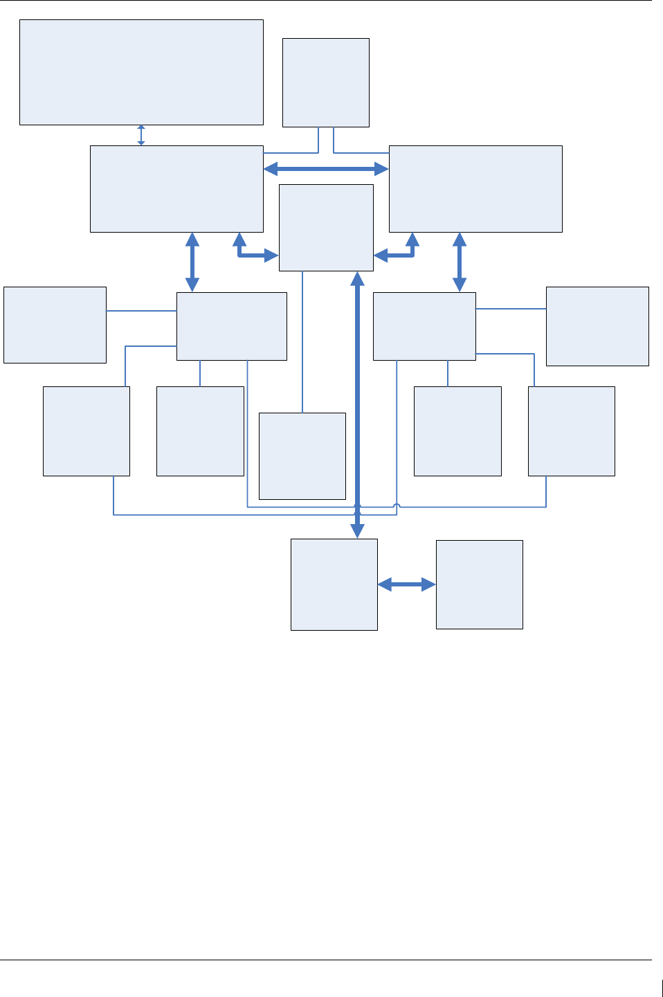
G1000/GFC700 System Maintenance Manual – C90A/C90GT/C90GTi King Air Page 3-23
190-00682-01 Revision G
No. 1 GDU 1040A PFD
Contains ‘ACTIVE’ PFD settings.
Represents ‘SET’ column for all
LRUs. Stores all configuration files in
internal memory. Uses master
configuration module for backup.
G1000 Master Configuration Module
(located in PFD backshell connector)
Master configuration module contains identical
backup configuration files of PFD configuration
memory. PFD cross-checks these backup files
against files contained with PFD memory. PFD self-
configures to match master configuration module.
GMA 1347
Contains ‘ACTIVE’
GMA settings. Uses
PFD internal
configuration files for
backup.
No. 1 GIA 63W
Contains ‘ACTIVE’
settings. Uses PFD
internal configuration
files for backup.
GDU 1500 MFD
Contains ‘ACTIVE’
MFD settings. The
MFD uses PFD
internal
configuration files
for backup.
No. 2 GDU 1040A PFD
Contains ‘ACTIVE’ PFD settings.
Represents ‘SET’ column for all
LRUs. Stores all configuration files in
internal memory. Uses master
configuration module for backup.
No. 2 GIA 63W
Contains ‘ACTIVE’
settings. Uses PFD
internal configuration
files for backup.
GMA 1347
Contains ‘ACTIVE’
GMA settings. Uses
PFD internal
configuration files for
backup.
No. 1 GTX 33
Contains
‘ACTIVE’
settings. Uses
PFD internal
configuration files
for backup.
No. 1 GEA 71
Contains
‘ACTIVE’
settings. Uses
PFD internal
configuration files
for backup.
No. 2 GEA 71
Contains
‘ACTIVE’
settings. Uses
PFD internal
configuration files
for backup.
No. 2 GTX 33
Contains
‘ACTIVE’
settings. Uses
PFD internal
configuration files
for backup.
GCU 475
Contains
‘ACTIVE’
settings. Uses
PFD internal
configuration files
for backup.
GMC 710
Contains
‘ACTIVE’
settings. Uses
PFD internal
configuration files
for backup.
GDL 69A
Contains
‘ACTIVE’
settings. Uses
PFD internal
configuration files
for backup.
GWX 68
Contains
‘ACTIVE’
settings. Uses
PFD internal
configuration files
for backup.
RS-232 RS-232
HIGH-SPEED DATABUS
(ETHERNET)
RS-232
RS-232 RS-232
RS-485
RS-485
RS-232
RS-232
RS-485
RS-485
Figure 3-15. G1000 LRU Configuration File Storage
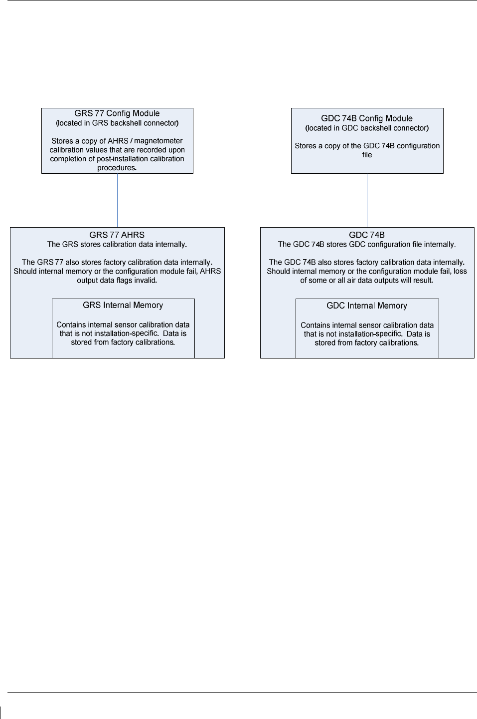
Page 3-24 G1000/GFC700 System Maintenance Manual – C90A/C90GT/C90GTi King Air
Revision G 190-00682-01
The GRS 77 and GDC 74B configuration modules function differently than the rest of the system. The
GDC 74B’s configuration file is loaded directly to GDC internal memory. A copy of the file is stored in
the GDC configuration module.
The GRS 77 configuration module does not store any configuration settings. Instead, it stores calibration
data recorded during installation calibration procedures.
Figure 3-16. GRS/GDC Configuration Settings Storage
G1000/GFC700 System Maintenance Manual – C90A/C90GT/C90GTi King Air Page 3-25
190-00682-01 Revision G
3.9 G1000 Software/Configuration Procedure
This section summarizes the procedures required to load software and configuration files to the G1000. It
is intended to work as a central guide for technicians to use while performing maintenance on the aircraft.
In sections of this manual where software is required to be reloaded, these sections will make reference
back to this Section for instructions. The technician should use proper judgment regarding the context of
maintenance required while following this section.
The following diagram depicts an overview of the software/configuration sequence for the G1000 system.
This applies mostly to a new G1000 system which has not previously been powered up and is for
informative purposes only.
GDU 1040A PFDs / GDU 1500 MFD Software Load
Software is first loaded to the MFD and PFDs. From the factory, G1000 units do
not contain useable software or configuration settings. Load software to PFD2
first then MFD and finally to PFD1.
G1000 System Upload Selection
After software is loaded to the MFD and PFDs, the displays should be placed in
configuration mode. Using PFD1, the technician goes to the System Upload
page. From the System Upload page, software files are selected to create an
automated profile to load. Once all desired files are checked, the G1000
automatically loads the selected files in the correct sequence to the LRUs.
G1000 System Software Verification
After software is loaded to the system, the technician verifies that each LRU
reports the correct version and software part number.
G1000 System Configuration Upload Selection
Following G1000 system software upload and verification, the aircraft specific
configuration files, as defined in the general arrangement drawing are loaded.
The aircraft general arrangement drawing will define the configuration files
appropriate to the specific aircraft serial number, STC modifications and
applicable AFMS.
G1000 Configuration Verification
After system configuration files are loaded, the technician verifies that the
correct configuration on the Airframe Configuration page.
Figure 3-17. Software/Configuration Overview
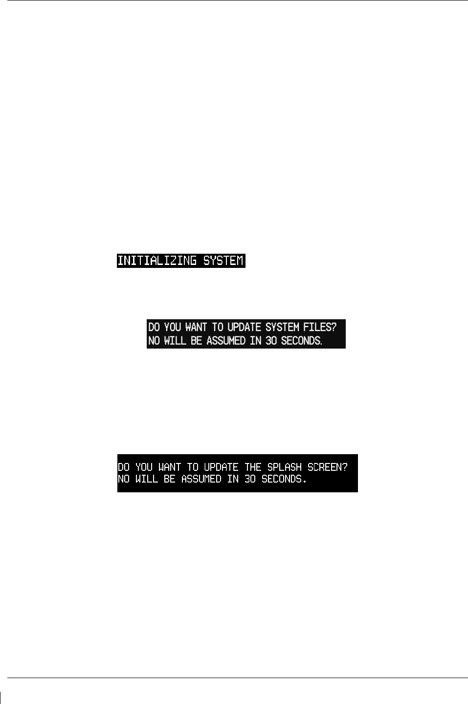
Page 3-26 G1000/GFC700 System Maintenance Manual – C90A/C90GT/C90GTi King Air
Revision G 190-00682-01
3.9.1 MFD & PFD Software Load
Follow this procedure to load software to either PFD or the MFD.
1. With the G1000 and GFC 700 powered on, pull the MFD, PFD 1 (PRI), PFD 1 (SEC), and PFD 2
circuit breakers.
2. Insert the correct G1000/C90 Loader Card into top card slot in the desired PFD or MFD.
NOTE
Refer to General Arrangement Drawing, listed in Table 1-2, for correct loader card part
number.
NOTE
If loading software to all displays, it is preferred to load PFD 2 first, followed by the MFD and
then PFD 1.
3. While holding the ENT key on the display, restore power by closing the appropriate circuit
breaker(s).
4. When the words appear in the upper left corner of the display,
release the ENT key.
5. Press the ENT key or the softkey labeled ‘YES’ to acknowledge the following prompt (see also
note below for MFD):
NOTE
For the MFD, use the far right soft key on the MFD in lieu of the ENT key where called out in
Steps 3 through 6. The ENT key for the MFD is located on the GCU 475 FMS controller and
will not function prior to software load.
6. New software is loaded to the PFD or MFD unit and the following screen is displayed:
7. Press the softkey labeled ‘NO’. Note that the splash screen may need to be loaded again after all
software and configuration loading is completed.
8. When complete, the display starts in configuration mode displaying the “System Status” page. Do
not remove power.
9. Remove the G1000/C90 Loader Card from the display and insert it into the top card slot on
another display if desired. Repeat Steps 3 through 8 as needed.
IMPORTANT!
For the rest of the software/configuration procedure, do not operate the MFD or
PFD 2 while loading software or configuration files unless specifically instructed to
do so. A failed or cancelled load may result.
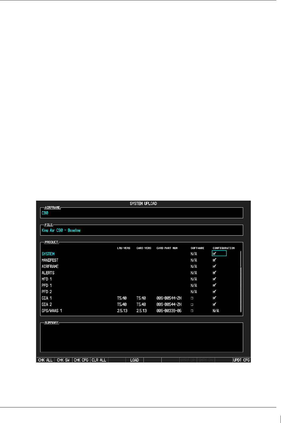
G1000/GFC700 System Maintenance Manual – C90A/C90GT/C90GTi King Air Page 3-27
190-00682-01 Revision G
3.9.2 G1000 System Software Upload
The System Upload page allows a technician to load LRU software and system configuration files
individually or in an automated sequence. Depending on what maintenance is performed, software and/or
configuration files may need to be reloaded to LRUs. Follow the steps below as a guide to use the
System Upload page.
IMPORTANT!
Do not allow power to be removed from the system when loading software. Remove
power only when instructed by the following procedure. As a general rule, all
displays should be in the same mode (configuration or normal) unless instructed
otherwise.
1. On PFD 1, go to the System Upload page using the small FMS knob.
2. Activate the cursor and use the small FMS knob to highlight ‘C90’ in the AIRFRAME field.
Press the ENT key to select the airframe type.
IMPORTANT!
Ensure that the correct airframe type is selected before proceeding; otherwise,
incorrect configuration information will be loaded.
3. Once an airframe type is selected the cursor moves to the FILE window. Rotate the small FMS
knob to active the drop-down menu. Move the cursor to highlight ‘King Air C90–Baseline’ and
press ENT.
Figure 3-18. System Upload Page
4. The PRODUCT window will populate and display software and default configuration file lists for
each G1000 LRU. The LRU VERS column shows the currently loaded software version in the
LRU, whereas the CARD VERS column shows the LRU software version stored on the loader
card. Each check designates a file to be loaded to the G1000.

Page 3-28 G1000/GFC700 System Maintenance Manual – C90A/C90GT/C90GTi King Air
Revision G 190-00682-01
If an inequality between the LRU VERS and CARD VERS columns is detected, the SOFTWARE
and CONFIGURATION boxes will be pre-selected (checked) for each LRU reporting a different
software version than the one on the card.
NOTE
With Software Image 0636.03, 0636.05 and subsequent, the hardware serial
number is used to determine appropriate software for the GMU 44 and GSA 8X
units. Until the software configuration loads sufficiently to determine this, the
GMU 44 and GSA 8X units will show as “INV” under the LRU VERS and CARD
VERS with two line items per unit (representing both possible hardware
configurations) on the System Upload Page. Once sufficient configuration is
loaded, the GMU 44 and GSA 8X units will appear normally on the System Upload
Page and will load automatically. If one of these units is missing entirely from the
System Upload Page, it is likely due to the hardware not reporting the serial
number. Serial number reporting can be verified on the System Status Page. Units
not reporting serial number will not accept software and will require replacement.
Reference Section 3.9.3 for general operation of the System Status Page.
The following softkeys provide an easy way to select files:
CHK ALL: Selects all files, both configuration and software
CHK SW: Selects all SW files only.
CHK CFG: Selects all configuration files only.
CLR ALL: Clears all selections.
LOAD: Starts the software loading process.
NOTE
When loading a new software image or re-loading software to a particular LRU, it
may not be necessary to reload all software and configuration files. The technician
should be sure of the software requirements and load the appropriate files, including
any options. If there is any doubt, the CHK ALL softkey is recommended.
5. After verifying that the desired software and configuration files are checked, press the LOAD
softkey. The G1000 system automatically begins loading software and default configuration files
to the selected LRUs in the proper order.
6. When the system finishes loading, it prompts the technician accordingly. Press the ENT key to
acknowledge that the upload is finished:
7.
Verify that each column indicates in green when the loading process has finished and
inspect the SUMMARY window as well to ensure that the load is successful.
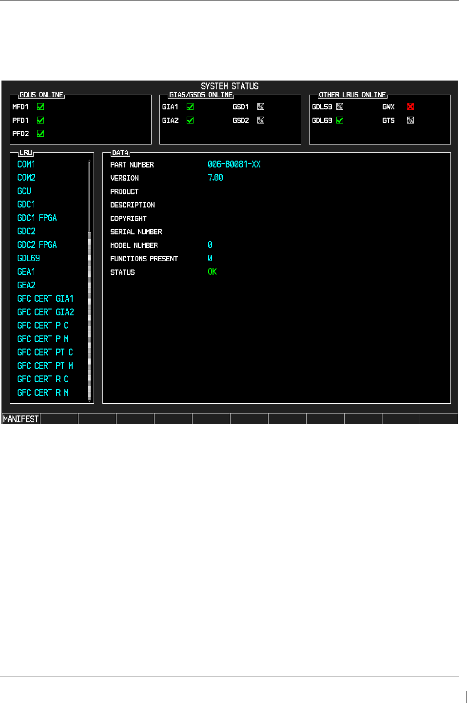
G1000/GFC700 System Maintenance Manual – C90A/C90GT/C90GTi King Air Page 3-29
190-00682-01 Revision G
3.9.3 Software Check
Anytime software and configuration loading procedures are accomplished during maintenance, it is
highly recommended to conduct a final software review of the system.
Figure 3-19. System Status
1. Start the PFD in Configuration Mode.
2. Go to the System Status page using the FMS knob. Activate the cursor and toggle to the LRU
window.
3. Highlight each of the following items in the LRU window, and verify that the software part
number and version matches the information in General Arrangement drawing listed in Table 1-2.
Record the results on the next page.
4. De-activate the cursor.
IMPORTANT!
It is essential that the software versions be checked and matched against the listed
versions in the General Arrangement drawing listed in Table 1-2. Software
Configuration is a critical part of the G1000 operation and must be verified before
returning an aircraft to service.

Page 3-30 G1000/GFC700 System Maintenance Manual – C90A/C90GT/C90GTi King Air
Revision G 190-00682-01
If any software version and/or part number does not match those specified by the
General Arrangement drawing, or if the software is not successfully loaded, DO
NOT continue with installation procedures. Troubleshoot and resolve the issue
before continuing (see Section 5.20).
Control & Display
SYSTEM SW VER OK SYSTEM SW VER OK SYSTEM SW VER OK
PFD 1 ______ PFD 2 FPGA ______ GCU ______
PFD 1 FPGA ______ MFD1 ______ GMC ______
PFD 2 ______ MFD1 FPGA ______
CNS:
SYSTEM SW VER OK SYSTEM SW VER OK SYSTEM SW VER OK
GIA1 ______ GPS2 ______ GDL69 ______
GIA2 ______ GTX1 ______ GWX ______
GMA1 ______ GTX2 ______ GWX FPGA ______
GMA2 ______ GIA1 AUDIO ______
GPS1 ______ GIA2 AUDIO ______
Sensors:
SYSTEM SW VER OK SYSTEM SW VER OK SYSTEM SW VER OK
GDC1 ______ GMU2 ______ GEA1 ______
GDC1 FPGA ______ GMU2 FPGA ______ GEA2 ______
GDC2 ______ GRS1 ______
GDC2 FPGA ______ GRS1 FPGA ______
GMU1 ______ GRS2 ______
GMU1 FPGA ______ GRS2 FPGA ______
AFCS SYSTEM:
SYSTEM SW VER OK SYSTEM SW VER OK SYSTEM SW VER OK
GSA PTCH CTL _____ GSA PTCH TRM M _____ GSA YAW CTL _____
GSA PTCH MON _____ GSA ROLL CTL _____ GSA YAW MON _____
GSA PTCH TRM C _____ GSA ROLL MON _____
AFCS CERT GAINS:
SYSTEM SW VER OK SYSTEM SW VER OK SYSTEM SW VER OK
GFC CERT GIA1 _____ GFC CERT PT C _____ GFC CERT YC _____
GFC CERT GIA2 _____ GFC CERT PT M _____ GFC CERT YM _____
GFC CERT PC _____ GFC CERT RC _____
GFC CERT PM _____ GFC CERT RM _____

G1000/GFC700 System Maintenance Manual – C90A/C90GT/C90GTi King Air Page 3-31
190-00682-01 Revision G
3.9.4 Loading Airframe Options
After the default configuration is loaded to the G1000, the technician must check and verify which
equipment or installation options exist on the aircraft. See the options list in 3.8.4.1.
If the C90A/C90GT aircraft being updated requires a different airframe configuration or is equipped with
any additional equipment options, follow this procedure to load them.
NOTE
ChartView and TAWS options are covered in a separate section. See Sections 3.9.6 and
3.9.7 for ChartView and TAWS, respectively.
NOTE
Coordinate configuration loading and activation with Sections 5, 6 and 7 as appropriate
for the actions being performed.
3.9.4.1 Determining Airframe Configuration
Aircraft in the following serial number range that have not been modified by the STCs listed below do not
require additional airframe configuration. Proceed to section 3.9.4.3 for option configuration.
Serial number range –
• 1361, 1363-1366, 1368-1372, 1374-1376, 1378-1383, 1385, 1387-1388, 1390-1393, 1395-1396, 1398-
1402, 1404-1410, 1412-1424,1426-1430, 1432-1497, 1499-1537, 1539, 1540-1726, 1728-1753,1755
STCs -
• SA10341SC Opt. 2- Installation of Pratt & Whitney Canada PT6A-135A engines and Hartzell HC-
D4N-3C/D9290(S)(K) or HC-E4N-3N/D8990S(K) propellers, Blackhawk STC
• SA10364SC - Installation of Pratt & Whitney Canada PT6A-135A engines and McCauley
4HFR34C762/94LMA-4 or 4HFR34C768/94LMA-4 propellers, Blackhawk STC
• SA3593NM - Installation of Hartzell/Raisbeck quiet turbofan propeller, Raisbeck STC
• SA10741SC - Installation of Pratt & Whitney Canada PT6A-135A engines and Hartzell HC-E4N-
3N/D8990S(K) or HC-B3TN-3( ,B,M)/T10173(E,B,NB,K,NK)-8 or McCauley
4HFR34C768/94LMA-4 propellers, Silverhawk STC
For C90GT aircraft or aircraft modified by Raisbeck and/or Blackhawk STCs above, refer to Table 5 of
the General Arrangement drawing (listed in Table 1-2) to determine applicable configuration.
Example-
A/C serial number - 1362
A/C modified by - SA3593NM (Raisbeck) STC with AFMS 86-206C
Configuration to be loaded – King Air C90A Configuration 7
Once the correct configuration is determined, load the appropriate C90A/C90GT configuration per
section 3.9.4.1.1 below.

Page 3-32 G1000/GFC700 System Maintenance Manual – C90A/C90GT/C90GTi King Air
Revision G 190-00682-01
IMPORTANT!
If the aircraft being modified has incorporated any modifications beyond factory
configuration or the STCs listed above that effect engine or airspeed limitation, your
configuration may not be supported at this time. It is the responsibility of the
installer to ensure compatibility with existing modifications.
3.9.4.1.1 Loading Airframe Configuration
1. While in configuration mode and loader card inserted in the top card slot of PFD 1, select the
“System Upload” page using the small FMS knob.
2. Activate cursor and rotate small knob to display drop down menu. Highlight “C90-
Configurations” or “C90-Configurations 2” and press ENT key on PFD 1.
3. Verify cursor drops down to the file box. Rotate the small FMS knob to view the list of available
C90 configurations.
4. Use the FMS small knob to select the correct configuration file as determined above. Press ENT.
5. Verify the correct configuration file is displayed in the “File” window (for example “King Air
C90A – Config 7”) then press “LOAD”.
6. Monitor load progress. Verify software load completes without errors as indicated by the
following:
a. Green “PASS” in Configuration column.
a. “Upload Complete………….COMPLETE” in the summary box.
7. Select ENT key on PFD 1 to acknowledge upload complete.
3.9.4.1.2 Airframe Configuration Load Confirmation
1. Use the large FMS knob to select the GDU page group and the small FMS knob to select
“AIRFRAME CONFIGURATION” page.
2. Verify the correct airframe configuration, as loaded above, is displayed in the
“IDENTIFICATION” window.
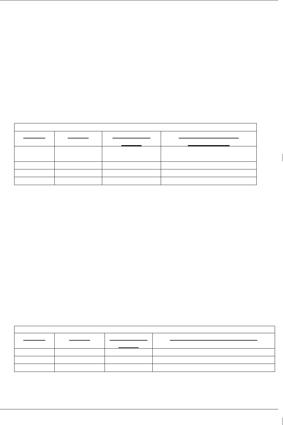
G1000/GFC700 System Maintenance Manual – C90A/C90GT/C90GTi King Air Page 3-33
190-00682-01 Revision G
3.9.4.2 Weight and Airspeed Configuration
In addition to the airframe configuration loaded above, certain installations will require additional steps to
configure the G1000 for airframe weight and airspeed markings.
3.9.4.2.1 Determining the Correct Weight Configuration
The C90A G1000 system software airframe configurations have specific default MTOW, MZFW, and
maximum landing weight values obtained from the effective AFMS for each configuration. Table 3-3
below lists the MTOW, MZFW, and maximum landing weights for each airframe configuration.
Reference Table 5 in the General Arrangement Drawing listed in Table 1-2 for airframe configuration
information.
DEFAULT AIRFRAME WEIGHT CONFIGURATIONS
MTOW MZFW Max Landing
Weight
Included In Airframe
Configurations
10,100 lbs No Limitation 9,600 lbs Baseline, 1, 2, 3, 4, 5, 6, 7, 8, 17,
19*, 20*, 21*, 22*
10,100 lbs 9,000 lbs 9,700 lbs 9, 10
10,350 lbs 9,000 lbs 9,700 lbs 11, 12, 13, 14, 15, 16
10,500 lbs 9,000 lbs 9,700 lbs 18
* For S/N 1063-1137 and 1146 have MTOW 9,650 and MLDW 9168. The MTOW 9,650 option
(ref. Table 3-4 or Table 3-5) must also be loaded to get the correct default weight configuration. For other
S/N applicable to these configurations, the weight configuration shown in this table applies.
Table 3-3. Default Airframe Weight Configurations
If your airframe configuration will require a weight configuration other than the default airframe weight
configuration listed in Table 3-3, then select an optional airframe weight configuration from Table 3-4 or
Table 3-5 below.
NOTE
Consult the aircraft AFMS and/or permanent maintenance records to determine the
correct airframe weight configuration for your aircraft installation.
If your installation is using C90 G1000 System Software PN 006-B0636-01, Version 0636.01, then select
an optional airframe weight configuration from Table 3-4. Proceed to Section 3.9.4.2.2, Loading
Airframe Weight Configurations.
OPTIONAL AIRFRAME WEIGHT CONFIGURATIONS FOR SW VERSION 0636.01
MTOW MZFW Max Landing
Weight
Optional Weight Configuration
9,650 lbs No Limitation 9,168 lbs King Air C90 – Weight LJ 1063-1137, 1146
10,100 lbs 9,000 lbs 9,700 lbs King Air C90 – 90-206CGW
10,350 lbs 9,000 lbs 9,700 lbs King Air C90 – 05-206CGW
Table 3-4. Optional Airframe Weight Configurations for SW Version 0636.01

Page 3-34 G1000/GFC700 System Maintenance Manual – C90A/C90GT/C90GTi King Air
Revision G 190-00682-01
If your installation is using C90 G1000 System Software PN 006-B0636-02, Version 0636.02 or
subsequent approved software versions, then select an optional airframe weight configuration from Table
3-5. Proceed to Section 3.9.4.2.2, Loading Airframe Weight Configurations.
OPTIONAL AIRFRAME WEIGHT CONFIGURATIONS FOR SW VERSION 0636.02 AND
SUBSEQUENT APPROVED REVISIONS
MTOW MZFW Max Landing
Weight
Optional Weight Configuration
9,650 lbs No Limitation 9,168 lbs King Air C90 – MTOW 9,650 lbs
10,100 lbs 9,000 lbs 9,700 lbs King Air C90 – MTOW 10,100 lbs
10,350 lbs 9,000 lbs 9,700 lbs King Air C90 – MTOW 10,350 lbs
10,500 lbs 9,000 lbs 9,700 lbs King Air C90 – MTOW 10,500 lbs
10,353 lbs 9,378 lbs 9,700 lbs King Air C90 – Centex MTOW 10,353 lbs*
10,485 lbs 9,378 lbs 9,832 lbs King Air C90 – Centex MTOW 10,485 lbs*
* Added with version 0636.03
Table 3-5. Optional Airframe Weight Configurations for SW Version 0636.02 and Subs
3.9.4.2.2 Loading Airframe Weight Configurations
Follow this procedure to enable the airframe weight configuration.
1. While in configuration mode and loader card inserted in the top card slot of PFD1, select the “System
Upload” page using the PFD1 small FMS knob.
2. Activate cursor in AIRFRAME window and rotate PFD1 FMS inner knob to display drop down
menu. Highlight “C90-Weight and Airspeed” and press ENT key on PFD1.
3. Verify cursor drops down to the file box. Rotate the inner FMS knob to view the list of available C90
configurations.
4. Use the FMS inner knob to select the correct airframe weight configuration file from either as
determined in Table 3-4 or Table 3-5 above. Press ENT.
5. Verify the correct configuration file is displayed in the “FILE” window (for example “King Air C90 –
MTOW 10,350 lbs”) then press “LOAD”.
6. Monitor load progress. Verify software load completes without errors as indicated by the following:
a. Green “PASS” in Configuration column.
b. “Upload Complete………….COMPLETE” in the summary box.
7. Select PFD1 ENT key to acknowledge upload complete.

G1000/GFC700 System Maintenance Manual – C90A/C90GT/C90GTi King Air Page 3-35
190-00682-01 Revision G
3.9.4.2.3 Loading Airspeed Indication Marking Configuration
Aircraft serial numbers LJ-1063 through LJ-1137 and LJ-1146 must load the airspeed configuration file
King Air C90 – Airspeed LJ 1063 – 1137,1146 .
Aircraft serial numbers LJ-1138-1299 except 1146, 1288, and 1295 must load the airspeed configuration
file King Air C90 – Airspeed LJ 1138-1299 Except 1146, 1288, and 1295.
All other aircraft not included in this serial number range are not required to load this additional airspeed
indication marking configuration.
Follow this procedure to enable the airspeed marking configuration.
1. While in configuration mode and loader card inserted in the top card slot of PFD1, select the “System
Upload” page using the PFD1 small FMS knob.
2. Activate cursor in AIRFRAME window and rotate PFD1 FMS inner knob to display drop down
menu. Highlight “C90-Weight and Airspeed” and press ENT key on PFD1.
3. Verify cursor drops down to the file box. Rotate the inner FMS knob to view the list of available C90
configurations.
4. Use the FMS inner knob to select the correct airspeed indicator marking configuration file. Press
ENT.
5. Verify the correct configuration file is displayed in the “FILE” window (for example “King Air C90 –
Airspeed LJ 1063 – 1137,1146”) then press “LOAD”.
6. Monitor load progress. Verify software load completes without errors as indicated by the following:
a. Green “PASS” in Configuration column.
b. “Upload Complete………….COMPLETE” in the summary box.
7. Select PFD1 ENT key to acknowledge upload complete.
3.9.4.2.4 Airspeed Configuration Load Confirmation
1. Accomplish Airspeed Test in Section 7.6.1 to verify the correct airspeed configuration, as loaded in
Section 3.9.4.2.3.
Aircraft LJ-1063 through LJ-1137, and LJ-1146: Vyse = 107 kts, Vmca = 90 kts , Vs1 = 89 kts
Aircraft LJ-1138 through 1299 except 1146, 1288, and 1295: Vyse = 108 kts, Vmca = 90 kts,
Vs1 = 88 kts

Page 3-36 G1000/GFC700 System Maintenance Manual – C90A/C90GT/C90GTi King Air
Revision G 190-00682-01
3.9.4.3 TIS Configuration
Follow this procedure to re-enable the TIS function if TAS has been enabled for the G1000 system.
TIS is a default G1000 system function. If TAS has not been enabled, the following procedure is not
required to enable the TIS function. If TAS has previously been enabled, perform the procedure below to
return TIS function to the G1000 system. The G1000 can only be configured for TIS or TAS but not
both.
IMPORTANT!
This procedure will re-load the C90A/C90GT/C90GTi baseline configuration. Any
options previously enabled such as DME, ADF etc will need to be re-enabled per the
instructions contained in this document.
1. On PFD 1, select the “System Upload” page using the small FMS knob.
2. Activate the cursor and use the small FMS knob to highlight “C90” in the AIRFRAME field.
Press the ENT key to select the airframe type.
IMPORTANT!
Ensure that the correct airframe type is selected before proceeding; otherwise,
incorrect configuration information will be loaded.
3. Once an airframe type is selected the cursor moves to the FILE window. Rotate the small FMS
knob to activate the drop-down menu. Move the cursor to highlight “King Air C90 Baseline”
and press ENT.
NOTE
The PRODUCT window displays information regarding each G1000 LRU. The LRU column
depicts the reported software version of the LRU, whereas the CARD VERS column shows the
LRU software version stored on the Loader Card. The SOFTWARE and CONFIGURATION
columns default to having all required boxes checked. Each checked file is automatically loaded
to the correct G1000 LRU.
4. Press the LOAD softkey.
5. Observe software loading progress and verify software load completes without errors as indicated
by the following:
b. Green “PASS” in Configuration column.
a. “Upload Complete………….COMPLETE” in the summary box.
6. Press ENT to acknowledge the “Upload Complete” box.
7. Reload all C90A/C90GT/C90GTI options as appropriate per instructions contained within this
document

G1000/GFC700 System Maintenance Manual – C90A/C90GT/C90GTi King Air Page 3-37
190-00682-01 Revision G
3.9.4.4 Traffic System Option Configuration
3.9.4.4.1 Traffic System Option
Follow this procedure to enable the traffic system function for the G1000 system.
NOTE
The G1000 can only be configured for TIS or TAS but not both. Performing this procedure will
automatically disable the TIS function.
2. While in configuration mode and the loader card is inserted in the top card slot of the PFD 1,
select the “System Upload” page on PFD 1 using the small FMS knob.
3. Activate cursor and rotate small knob to display drop down menu. Verify “C90-Options” is
highlighted and press ENT key on PFD 1.
4. Verify cursor drops down to the file box. Rotate the small FMS knob to view the list of available
C90 options.
5. Use the FMS small knob to select “King Air C90 – Traffic System Option”. Press ENT key on
PFD 1.
6. Verify the “King Air C90 – Traffic System Option” configuration file is displayed in the “File”
window. Press “LOAD”.
7. Monitor load progress. Verify software load completes without errors as indicated by the
following:
a. Green “PASS” in Configuration column.
b. “Upload Complete………….COMPLETE” in the summary box.
8. Select ENT on PFD 1 to acknowledge upload complete.
3.9.4.4.2 Configuration of Navigation Map for Traffic System
1. With the MFD in Normal Mode, use the GCU FMS knob to select the Navigation Map page then
press GCU MENU key to display the PAGE MENU.
2. Turn the small right knob to select or verify selected ‘Map Setup’ and press the ENT key and
verify TRAFFIC is selected ON.
3. Verify the flashing cursor highlights the GROUP’ field.
4. Turn the small FMS knob to select Traffic and press ENT on the GCU.
5. Turn the large FMS knob to select Traffic Mode option ALL TRAFFIC.
6. Turn the small FMS knob to select the desired option and press the ENT key on the GCU.
Repeat the step for Traffic Symbol and Traffic Label. Ensure TRAFFIC SMBL is 300NM and
TRAFFIC LBL is 300NM.

Page 3-38 G1000/GFC700 System Maintenance Manual – C90A/C90GT/C90GTi King Air
Revision G 190-00682-01
7. Return to the Map Page by pressing the FMS knob or momentarily pressing and holding the CLR
key. Deactivate cursor.
3.9.4.5 Garmin GTS 8XX Traffic System (Configuration Placeholder)
NOTE
This STC does not approve the installation or configuration of the GTS 8XX traffic system.
3.9.4.6 Stormscope (WX-500) Option Configuration
3.9.4.6.1 Stormscope (WX-500) Option
Follow this procedure to enable the WX-500 (Stormscope) function for the G1000 system
1. While in configuration mode on PFD 1 and loader card inserted into top slot of PFD 1, select the
“System Upload” page using the PFD 1 small FMS knob.
2. Activate cursor and rotate small knob to display drop down menu. Verify “C90-Options” is
highlighted and press ENT on PFD 1.
3. Verify cursor drops down to the file box. Rotate the small FMS knob to view the list of available
C90 options.
4. Use the FMS small knob to select “King Air C90 – WX 500 Option”. Press ENT on PFD 1.
5. Verify the “King Air C90 – WX 500 Installation Option” configuration file is displayed in the
“File” window. Press “LOAD”.
6. Monitor load progress. Verify software load completes without errors as indicated by the
following:
a. Green “PASS” in Configuration column.
b. “Upload Complete………….COMPLETE” in the summary box.
7. Select ENT on PFD 1 to acknowledge upload complete. Deactivate cursor.
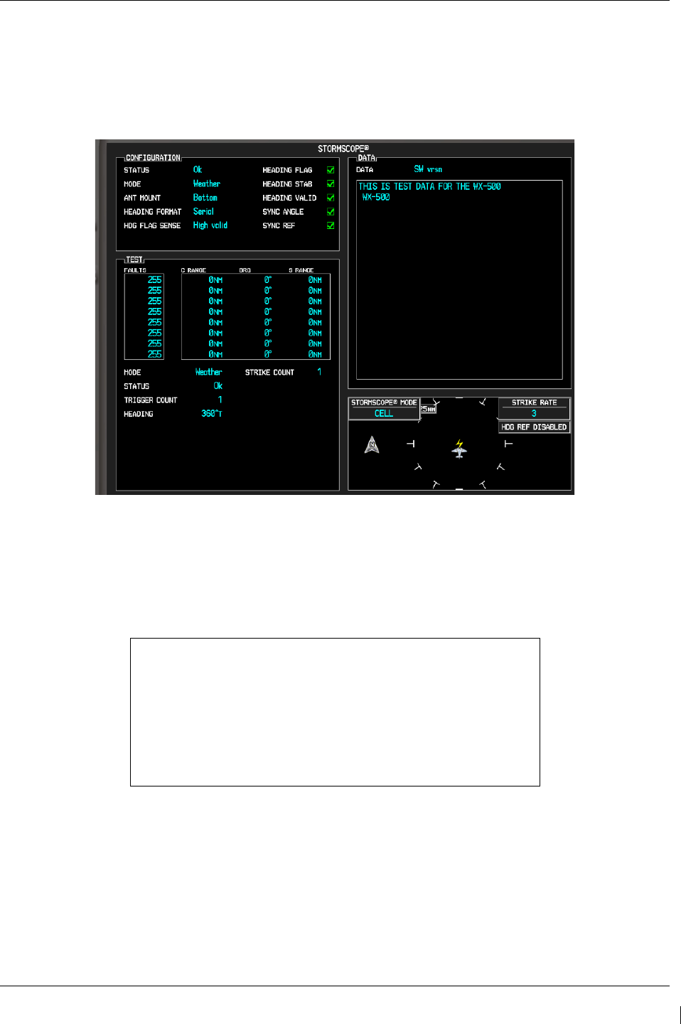
G1000/GFC700 System Maintenance Manual – C90A/C90GT/C90GTi King Air Page 3-39
190-00682-01 Revision G
3.9.4.6.2 WX-500 Stormscope Configuration Load Confirmation.
1. With PFD 1 in Configuration Mode, use the PFD 1 large FMS knob to select OTHER and the
Stormscope configuration page.
StormScope Configuration Page (Reference Only)
2. Activate the cursor and highlight the DATA field. Use the small FMS knob to select ‘Config’
and press the ENT key on the MFD.
3. Verify that the DATA window shows the following:
Hdg: None: J3-1 Jumper
J3-2 Jumper
Hdg Valid Flag No Flag
Flag Sense +invld
J3-4 Open
Hdg Value <aircraft heading>
Inhibit Line Off
Antenna Mount Bottom
J3-3 Open
4. Deactivate the cursor.
NOTE
The DATA window is only updated once every five seconds.

Page 3-40 G1000/GFC700 System Maintenance Manual – C90A/C90GT/C90GTi King Air
Revision G 190-00682-01
3.9.4.7 ADF – 60 Option Configuration
1. While in configuration mode on PFD 1 and with the loader card in the top slot of PFD 1, use the
large FMS knob to select the SYSTEM group. Select “SYSTEM UPLOAD” page using the
small FMS knob.
2. Activate cursor and rotate small knob to display drop down menu. Verify “C90-Options” is
highlighted and press ENT on PFD 1.
3. Verify cursor drops down to the file box. Rotate the small FMS knob to view the list of available
C90 options.
4. Use the FMS small knob to select “King Air C90 – ADF-60 Option”. Press ENT on PFD 1.
5. Verify the “King Air C90 – ADF-60 Option” configuration file is displayed in the “File”
window. Press “LOAD” on PFD 1.
6. Monitor load progress. Verify software load completes without errors as indicated by the
following:
a. Green “PASS” in Configuration column for GIA2, GMA PIL, and GMA COPIL.
b. “Upload Complete………….COMPLETE” in the summary box.
7. Select ENT on PFD 1 to acknowledge upload complete. Deactivate cursor.
3.9.4.8 RAD ALT (Configuration Placeholder)
NOTE
This STC does not approve the installation or configuration of a radio altimeter.
3.9.4.9 DME 42 Option Configuration
1. While in configuration mode on PFD 1 and with the loader card in the top slot of PFD 1, use the
large FMS knob to select the SYSTEM group. Select “SYSTEM UPLOAD” page using the
small FMS knob.
2. Activate cursor and rotate small knob to display drop down menu. Verify “C90-Options” is
highlighted and press ENT on PFD 1.
3. Verify cursor drops down to the file box. Rotate the small FMS knob to view the list of available
C90 options.
4. Use the FMS small knob to select “King Air C90 – DME-42 Option”. Press ENT on PFD 1.
5. Verify the “King Air C90 – DME-42 Option” configuration file is displayed in the “File”
window. Press “LOAD” on PFD 1.
6. Monitor load progress. Verify software load completes without errors as indicated by the
following:
a. Green “PASS” in Configuration column for GIA1, GMA PIL, and GMA COPIL.

G1000/GFC700 System Maintenance Manual – C90A/C90GT/C90GTi King Air Page 3-41
190-00682-01 Revision G
b. “Upload Complete………….COMPLETE” in the summary box.
7. Select ENT on PFD 1 to acknowledge upload complete. Deactivate cursor.
3.9.4.10 GSR 56 Stand-Alone (Configuration Placeholder)
NOTE
This STC does not approve the installation or configuration of the GSR 56 system.
3.9.4.11 GTX 33 Extended Squitter (ES) Option Configuration
NOTE
The GTX 33 Transponder Part Number 011-00779-10 will require an upgrade to support ES
functionality prior to enabling the GTX 33 ES Option and must be routed to the Garmin Service
Center for this upgrade. If GTX 33 ES Transponder Part Number 011-00779-30 is installed in
the aircraft, then the GTX 33 ES Option can be enabled. Reference the C90 General Arrangement
Drawing 005-00375-22 for GTX 33 Transponder LRU software and version part numbers
compatible with extended squitter functionality.
1. While in configuration mode on PFD 1 and with the loader card in the top slot of PFD 1, use the
large FMS knob to select the SYSTEM group. Select “SYSTEM UPLOAD” page using the
small FMS knob.
2. Activate cursor and rotate small knob to display drop down menu. Verify “C90-Options” is
highlighted and press ENT on PFD 1.
3. Verify cursor drops down to the file box. Rotate the small FMS knob to view the list of available
C90 options.
4. Use the FMS small knob to select “King Air C90 – GTX 33 ES Option”. Press ENT on PFD 1.
5. Verify the “King Air C90 – GTX 33 ES Option” configuration file is displayed in the “File”
window. Press “LOAD” on PFD 1.
6. Monitor load progress. Verify software load completes without errors as indicated by the
following:
a. Green “PASS” in Configuration column for GIA1, GIA2, GTX1, and GTX2.
b. “Upload Complete………….COMPLETE” in the summary box.
7. Select ENT on PFD 1 to acknowledge upload complete. Deactivate cursor.
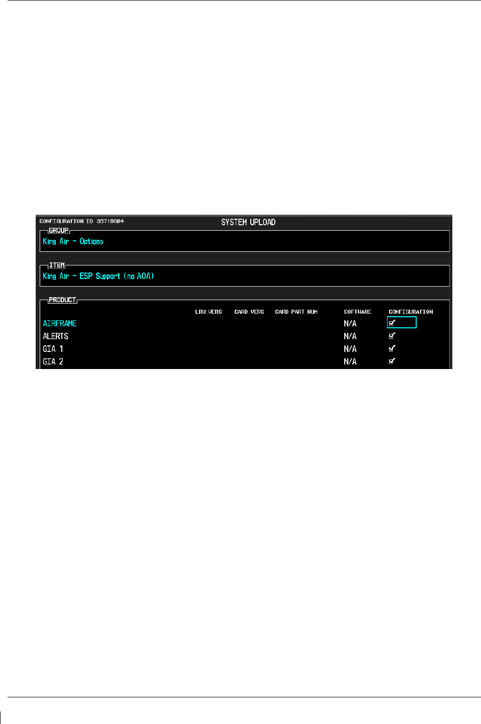
Page 3-42 G1000/GFC700 System Maintenance Manual – C90A/C90GT/C90GTi King Air
Revision G 190-00682-01
3.9.4.12 ESP Support Option Configuration
This section applies only to installations with the ESP option (software version 0636.03 and later). The
procedures outlined in this section must be followed to load the necessary configuration files required to
enable ESP messages and functions. An Enhanced AFCS unlock card is also required for this option (see
Section 3.9.12.)
1. With the loader card in the top slot of PFD1 and PFD1 in configuration mode, select the
“SYSTEM UPLOAD” page using the small FMS knob on PFD1.
2. Activate cursor and rotate the small FMS knob to display drop down menu. Highlight King Air
C90- Options and press ENT key on PFD1.
3. Rotate the small FMS knob to highlight “ESP Support”. Press ENT key on PFD1.
4. Verify “ESP Support (no AOA)” is displayed in the “Item” window. Press “LOAD”.
Figure 3-20. ESP Support Configuration
5. Monitor load progress. Verify software load completes without errors as indicated by the
following:
• Green “PASS” in Configuration column for AIRFRAME, ALERTS, GIA1 and GIA2.
• “Upload Complete………….COMPLETE” in the summary box.
6. Press ENT key on PFD1 to acknowledge upload complete.
7.
Deactivate cursor.
3.9.4.13 GSM 85A / GSM 86 Servo Gearbox Configuration
For software versions 0636.03 and later, the section 4.9.1 slip clutch torque check procedure requires the
correct type of GSM servo gearbox to be configured. It is not required to load this configuration if
GSM 86 servo gearboxes are installed (default configuration) unless GSM 85A servo gearboxes have
been previously configured.
1. With the loader card in the top slot of PFD1 and PFD1 in configuration mode, select the
“SYSTEM UPLOAD” page using the small FMS knob on PFD1.
2. Activate cursor and rotate the small FMS knob to display drop down menu. Highlight King Air
C90 - Options and press ENT key on PFD1.
3. Rotate the small FMS knob to highlight “King Air C90– GSM 85A Servo Mounts” or “King
Air C90– GSM 86 Servo Mounts”, as applicable. Press ENT key on PFD1.
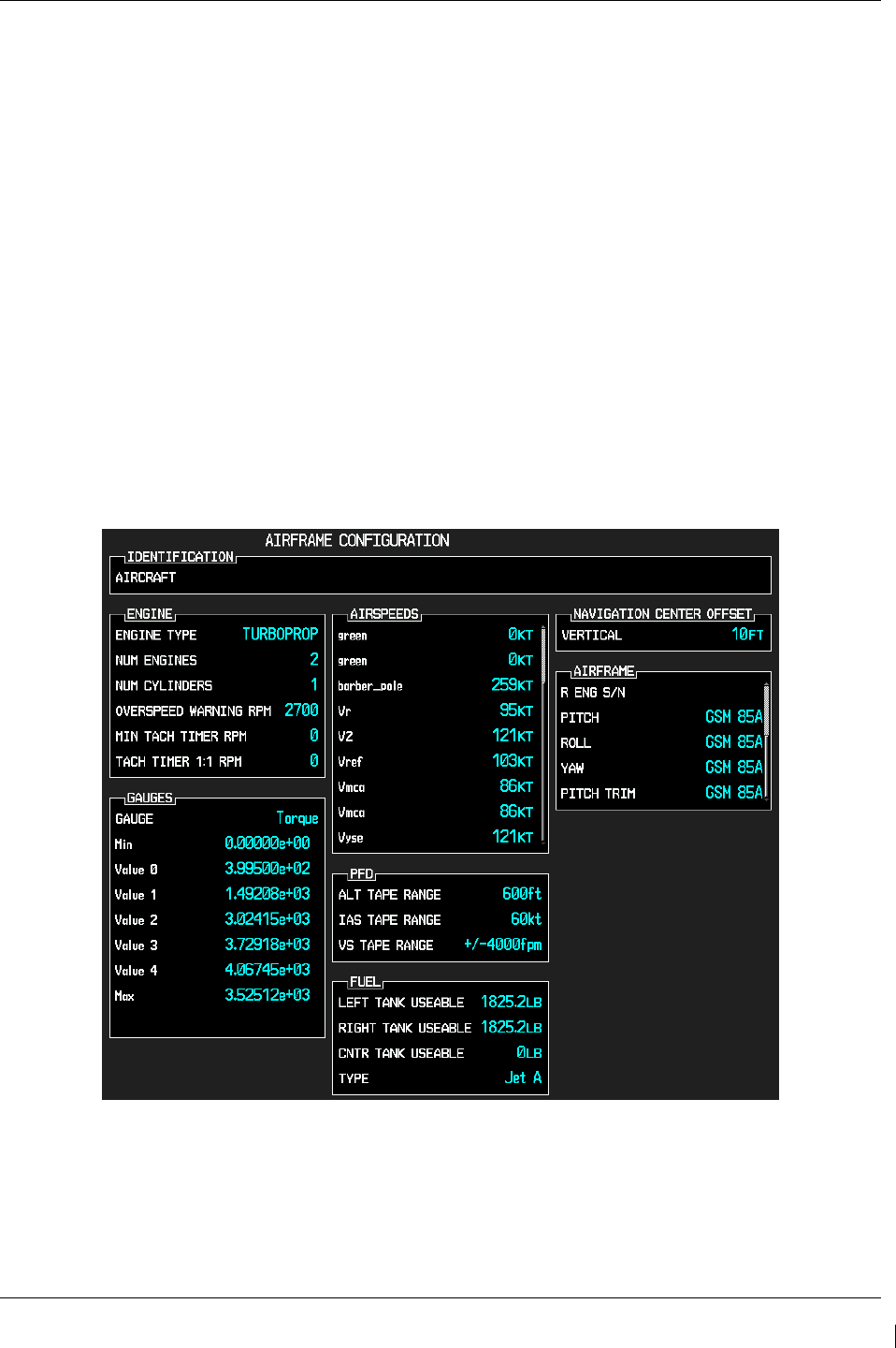
G1000/GFC700 System Maintenance Manual – C90A/C90GT/C90GTi King Air Page 3-43
190-00682-01 Revision G
4. Verify the intended selection is displayed in the “Item” window.
5. Press “LOAD”.
6. Monitor load progress. Verify software load completes without errors as indicated by the
following:
• Green “PASS” in Configuration column for PITCH SERVO, PITCH TRIM SERVO, ROLL
SERVO and/or YAW SERVO (as selected).
• “Upload Complete………….COMPLETE” in the summary box.
7. Press ENT key on PFD1 to acknowledge upload complete.
8. Deactivate cursor.
9. Verify the servo gearbox configuration as follows:
a. With PFD1 in configuration mode, use the large FMS knob on PFD1 to select the GDU page,
then select “AIRFRAME CONFIGURATION” using the small FMS knob.
b. Activate cursor and rotate the large FMS knob to scroll to the last entries in the AIRFRAME
field.
c. Verify the correct type of GSM servo gearbox (GSM 85A or GSM 86) is installed for each
servo.
Figure 3-21. Servo Mount Configuration Verification
d. Deactivate the cursor.

Page 3-44 G1000/GFC700 System Maintenance Manual – C90A/C90GT/C90GTi King Air
Revision G 190-00682-01
3.9.4.14 Flight Charts Configuration
Follow this procedure to re-enable FliteCharts function if ChartView has been enabled for the G1000
system.
FliteCharts is a default G1000 system function. Section 3.9.8 installs the Terrain/Obstacle database card,
which includes FliteCharts database. If ChartView has not been enabled, the following procedure is not
required. If ChartView has previously been enabled, perform the procedure below to return FliteCharts
function to the G1000 system.
IMPORTANT!
This procedure will re-load the C90A/C90GT/C90GTi baseline configuration. Any
options previously enabled such as DME, ADF etc will need to be re-enabled per the
instructions contained in this document.
NOTE
The G1000 can only be configured for FliteCharts or ChartView but not both. Performing this procedure
will automatically disable the ChartView function.
1. With PFD 1 in Configuration Mode and the loader card inserted in the top card slot of PFD 1,
select the “System Upload” page on PFD 1 using the small FMS knob.
2.
Activate the cursor and use the small FMS knob to highlight “C90” in the AIRFRAME field. Press the
ENT key to select the airframe type.
3. Once the airframe type is selected the cursor moves to the FILE window. Rotate the small FMS
knob to activate the drop-down menu. Move the cursor to highlight “King Air C90 Baseline”
and press ENT.
NOTE
The PRODUCT window displays information regarding each G1000 LRU. The LRU column
depicts the reported software version of the LRU, whereas the CARD VERS column shows the
LRU software version stored on the Loader Card. The SOFTWARE and CONFIGURATION
columns default to having all required boxes checked. Each checked file is automatically loaded
to the correct G1000 LRU.
4. Press the LOAD softkey.
5. Observe software loading progress and verify software load completes without errors as
indicated by the following:
a. Green “PASS” or N/A in the Configuration column.
b. “Upload Complete………….COMPLETE” in the summary box.
6. Press ENT to acknowledge the “Upload Complete” box.
7. Reload other C90 options as appropriate per instructions contained within this document.
G1000/GFC700 System Maintenance Manual – C90A/C90GT/C90GTi King Air Page 3-45
190-00682-01 Revision G
3.9.5 SafeTaxi Configuration
SafeTaxi is loaded and configured on the G1000 by default and needs no more configuring. Section
3.9.8 installs the Terrain/Obstacle database card, which includes SafeTaxi database.
3.9.6 ChartView Configuration
Follow this procedure to re-activate the ChartView option. A ChartView Enable Card, as specified in the
General Arrangement Drawing listed in Table 1-2, will be required for this procedure.
NOTE
When the ChartView option is enabled for the first time (normally with the initial STC installation), the
G1000 writes its unique system ID to the physical card and locks the files to this unique ID. This
prevents the unlock card from ever being used to activate the ChartView feature in other G1000 systems.
The unlock card is forever tied to the specific aircraft in which it was used for the first time. For
situations where ChartView must be re-activated, this card must be used.
NOTE
The required ChartView databases are subscription-based and are to be procured by the installing agency
directly from Jeppesen. This procedure is only required if the ChartView option is purchased by the
customer.
NOTE
The G1000 can only be configured for FliteCharts or ChartView but not both. Performing this procedure
will automatically disable the FliteCharts option. ChartView databases are required to be installed on the
terrain database cards to function (see Section 3.9.8).
1. Remove power from the PFD 1, PFD 2 and MFD by opening the PFD 1 PRI, PFD 1 SEC, PFD 2
and MFD circuit breakers.
2. A ChartView Enable card is required to activate this feature. Insert the ChartView Enable card in
the upper slot of the PFD 1.
3. While holding the ENT key on PFD 1, PFD 2 and MFD, restore power to the displays by closing
the PFD and MFD circuit breakers.
4. When the words appear in the upper left corner of the displays,
release the ENT key.
5. On PFD 1, go to the System Upload page using the FMS knob.
6. Activate the cursor. Use the small FMS knob to select ‘CONFIGURATION FILES’ in the
AIRFRAME field and press the ENT key.
7. Highlight the FILE field. Use the small FMS knob to select the “Enable ChartView” option
and press the ENT key. Once the option is selected the configuration files in the SECTION field
will be displayed. All files should be checked. If not, press the CHK ALL softkey.
8. Press the LOAD softkey.
9. Monitor the status of the upload. When the upload is finished, press the ENT key to
acknowledge the upload complete confirmation.
10. View the SUMMARY field and ensure that the item is ‘COMPLETED’.
11. De-activate the cursor.
12. Power down the system and remove the ChartView Enable card from PFD 1.
Page 3-46 G1000/GFC700 System Maintenance Manual – C90A/C90GT/C90GTi King Air
Revision G 190-00682-01
3.9.7 TAWS B Enable
Follow this procedure to re-activate the TAWS Class B option. A TAWS Enable Card, as specified on
General Arrangement Drawing, listed in Table 1-2, will be required for this procedure. Section 3.9.8
installs the Terrain/Obstacle database card.
NOTE
The G1000 has various features that require the use of unlock/enable cards to activate the feature.
Throughout this document these cards are generically referred to as ‘enable cards’. In some cases, the
actual label on the physical card may say ‘unlock’. If uncertain, the technician should verify the card part
number prior to use.
NOTE
When the TAWS option is enabled for the first time (normally with the initial STC installation), the
G1000 writes its unique system ID to the physical card and locks the files to this unique ID. This
prevents the enable card from ever being used to activate TAWS in another G1000 system. This enable
card is tied to the specific aircraft in which it was used for the first time. For situations where TAWS
must be re-activated, this card must be used.
1. If not applied, apply power to the G1000 system.
2. Remove power from PFD 1, PFD 2 and MFD by opening the PFD 1 PRI/SEC, PFD 2 and MFD
circuit breakers.
3. Insert the TAWS Class B Enable card in the upper slot of PFD 1.
4.
While holding the ENT key on the PFD 1, PFD 2 and MFD (for MFD press and hold the farthest
right pushbutton), restore power to the displays.
5.
When the words appear in the upper left corner of the displays,
release the ENT key
.
6. On PFD 1, go to the System Upload page using the small PFD 1 FMS knob.
7. Activate the cursor. Use the small PFD 1 FMS knob to select CONFIGURATION FILES in
the AIRFRAME field and press the PFD 1 ENT key.
8. Highlight the FILE field. Use the PFD 1 small FMS knob to select the ‘Enable TAWS’ option
and press the PFD 1 ENT key. Once the option is selected, the configuration files in the
PRODUCT field will be displayed. All files should be checked. If not, press the CHK ALL
softkey.
9. Press the LOAD softkey.
10. Monitor the status of the upload. When the upload is finished, press the PFD 1 ENT key to
acknowledge the upload complete confirmation.
11. View the SUMMARY field and ensure that the item is ‘COMPLETE’.
12. De-activate the cursor.
13. Power down the system and remove the TAWS Enable card from PFD 1.
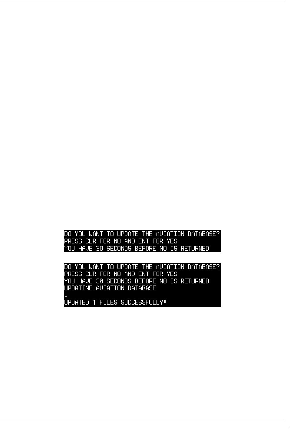
G1000/GFC700 System Maintenance Manual – C90A/C90GT/C90GTi King Air Page 3-47
190-00682-01 Revision G
3.9.8 Terrain/Obstacle Database Cards
NOTE
If the G1000 is to be equipped with the FliteCharts or ChartView display options, the appropriate
databases are required to be loaded onto the Terrain/Obstacle cards before they are installed in the
displays. ChartView database subscription services must be procured directly from Jeppesen and are
usually sourced by the aircraft owner. Further, the ChartView feature must be ‘enabled’ before the
G1000 can use the databases (see Section 3.9.6).
There is no enable card for Garmin FliteCharts. A single cycle of Garmin FliteCharts is loaded on the
database cards when they are manufactured at Garmin. Additional FliteCharts database updates are
obtained directly from Garmin’s web site and are updated on a periodic basis. The G1000
automatically detects the FliteCharts databases and activates the display feature. If the G1000 detects
a ChartView database and a FliteCharts database, it will always activate the ChartView database.
1. Open PFD 1 PRI, PFD 1 SEC, PFD 2 and MFD circuit breakers.
2. Insert the current Terrain/Obstacle database cards into the lower slots of PFD 1, PFD 2, and the
MFD. Refer to the General Arrangement drawing (listed in Table 1-2) for correct card part
numbers.
3. Close the PFD 1 PRI, PFD 1 SEC, PFD 2 and MFD circuit breakers.
3.9.9 Aviation Database Loading & Update
1. Open PFD 1 PRI, PFD 1 SEC, PFD 2 and MFD circuit breakers.
2. Insert a database card containing the Jeppesen aviation database (database supplied by Jeppesen)
into the top slot of PFD 2.
3. Apply power to PFD 2. The following prompt is displayed in the upper left corner of the PFD:
4. Press the PFD 2 ENT key to confirm the database update. The following prompt is displayed:
5. After the update completes, PFD 2 starts in normal mode. Remove the aviation database update
card from PFD 2.
6. Repeat steps 2 through 4 for the MFD (for MFD, press and hold the farthest right push button).
Repeat again for PFD 1. The aviation databases are now updated.
7. Confirm that the correct update cycle and version is loaded at the power-up page of the MFD.
8. Remove the aviation database update card from PFD 1.
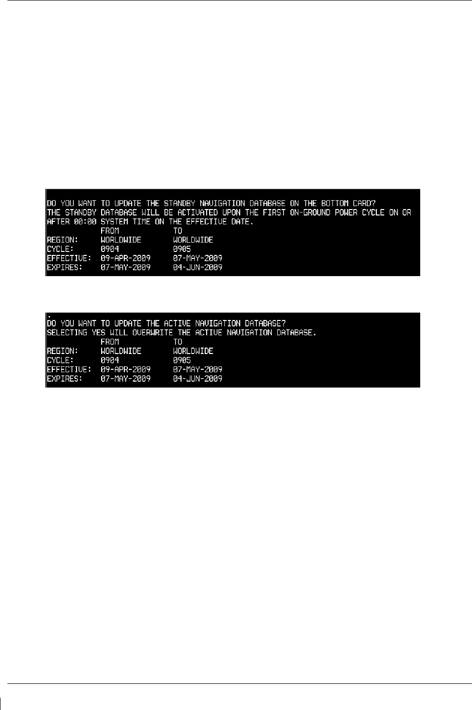
Page 3-48 G1000/GFC700 System Maintenance Manual – C90A/C90GT/C90GTi King Air
Revision G 190-00682-01
3.9.10 Navigation Database Loading
A new navigation database cycle may be loaded before it is effective. The new database will be stored on
the G1000 bottom SD card until it becomes effective. The G1000 will automatically update to use the
new database at the first on-ground power-on after its effectivity date.
Follow this procedure to load the navigation database:
1. Remove power from the PFD1, PFD2 and MFD.
2. Insert an SD card containing the latest cycle Jeppesen navigation database (data supplied by
Jeppesen) into the top slot of the MFD.
3. Apply power to the PFD1, PFD2 and MFD. A prompt similar to the following will be displayed
on the MFD:
4. Select the YES softkey to confirm the standby navigation database update.
5. After the database is updated, a prompt similar to the following will be displayed on the MFD:
6. Select the NO softkey to allow the system to use the database when it becomes effective.
NOTE
If the new database is not yet effective but it is desired to use the new database
immediately, select the YES softkey. To eliminate database mismatch errors when
selecting the YES softkey, the database must also be loaded on PFD1 and PFD2
individually following the same process.
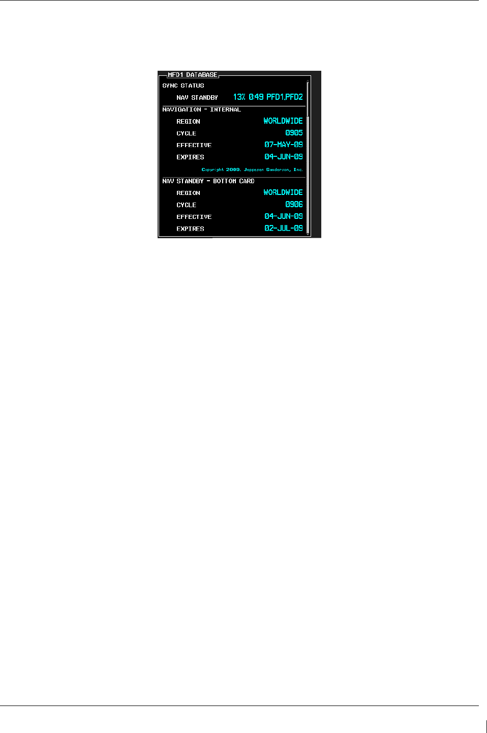
G1000/GFC700 System Maintenance Manual – C90A/C90GT/C90GTi King Air Page 3-49
190-00682-01 Revision G
7. The system will synchronize and automatically update as necessary. Monitor the synchronization
process on the AUX – SYSTEM STATUS page in the SYNC STATUS sub-section within the
DATABASE window This sub-section is only present when a sync is occurring or has occurred
on the current power cycle.
Figure 3-22. Navigation Database Synchronization
8. If an error occurs during synchronization, one of the following messages will be displayed
followed by the affected GDU:
Err No Space – SD card does not contain sufficient memory
Timeout – system timed-out prior to the database transfer completing
Err – displayed for all other errors
Note that a power cycle is required to restart synchronization when ‘Err No Space’ or ‘Err’ is
shown.
9. When the synchronization is complete, the status is shown as ‘Complete’.
10. Cycle power to PFD1, PFD2 and MFD by resetting the PFD1 PRI, PFD1 SEC, PFD2 and MFD
circuit breakers.
11. The standby navigation databases in PFD1, PFD2 and MFD are now updated.
12. On the AUX – SYSTEM STATUS page, press the MFD1 DB softkey. Scroll through all of the
databases contained in the MFD and confirm that the correct databases are loaded.
13. Press the MFD1 DB softkey again to toggle to PFD1 DB. Scroll through all of the databases
contained in the PFD1 and confirm that the correct databases are loaded.
14. Press the PFD1 DB softkey again to toggle to PFD2 DB. Scroll through all of the databases
contained in the PFD2 and confirm that the correct databases are loaded.
Page 3-50 G1000/GFC700 System Maintenance Manual – C90A/C90GT/C90GTi King Air
Revision G 190-00682-01
3.9.11 SVS/Pathways Enable
Follow this procedure to enable the Synthetic Vision option. An SVS/Pathways Enable Card, as
specified on General Arrangement Drawing 005-00375-22, will be required for this procedure.
NOTE
The Garmin Synthetic Vision and Pathways feature requires 9 arc-second high
resolution terrain databases to function. Each G1000 display must be equipped
with the Terrain/Obstacle/SafeTaxi database card installed in the lower slot.
NOTE
When the SVS/Pathways option is enabled for the first time the G1000 writes
its unique system ID to the physical card and locks the files to this unique ID.
This prevents the SVS/Pathways unlock card from ever being used to activate
the SVS/Pathway feature in other G1000 systems.
The unlock card is tied to the specific aircraft in which it was used for the first
time. This card MUST be kept with the aircraft for situations where
SVS/Pathways must be re-activated.
1. If not applied, apply power to the G1000 system.
2. Remove power from PFD1, PFD2 and MFD by opening the PFD1 PRI/SEC, PFD2 and MFD
circuit breakers.
3. Insert the SVS Enable card in the upper slot of PFD1.
4. While holding the ENT key on the PFD1, PFD2 and MFD (for MFD press and hold the farthest
right pushbutton), restore power to the displays.
5. When the words appear in the upper left corner of the displays,
release the ENT key.
6. On PFD1, go to the System Upload page using the small PFD1 FMS knob.
7. Activate the cursor. Use the small PFD1 FMS knob to select CONFIGURATION FILES in the
AIRFRAME field and press the PFD1 ENT key.
8. Highlight the FILE field. Use the PFD1 small FMS knob to select the ‘Enable SVS’ option and
press the PFD1 ENT key. Once the option is selected, the configuration files in the PRODUCT
field will be displayed. All files should be checked. If not, press the CHK ALL softkey.
9. Press the LOAD softkey.
10. Monitor the status of the upload. When the upload is finished, press the PFD1 ENT key to
acknowledge the upload complete confirmation.
11. View the SUMMARY field and ensure that the item is ‘COMPLETE’.
12. De-activate the cursor.
13. Power down the system and remove the Enable card from PFD1.
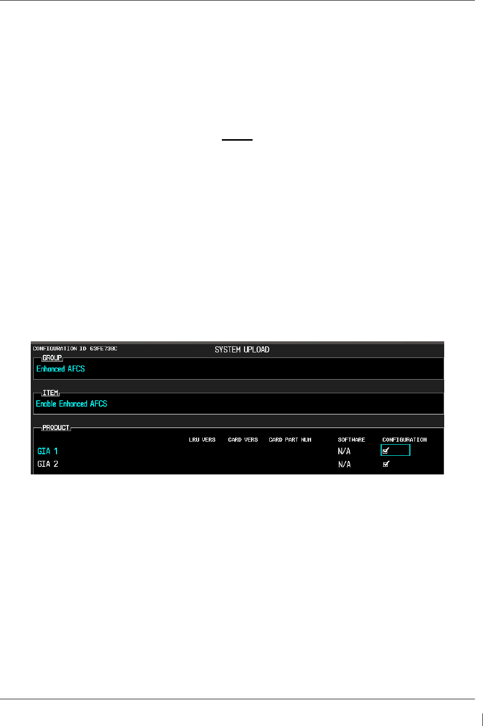
G1000/GFC700 System Maintenance Manual – C90A/C90GT/C90GTi King Air Page 3-51
190-00682-01 Revision G
3.9.12 ESP Enable
Follow this procedure to enable the Electronic Stability and Protection (ESP) function. An Enhanced
Enhanced AFCS Unlock Card, as specified on General Arrangement Drawing 005-00375-22, will be
required for this procedure. Ensure that the “ESP Support (no AOA)” configuration has been loaded per
Section 3.9.4.12.
NOTE
The G1000 has various features that require the use of unlock/enable cards to
activate the feature. Throughout this document these cards are generically
referred to as ‘enable car
ds’. In some cases, the actual label on the physical card
may say ‘unlock’. If uncertain, the technician should verify the card part
number prior to use.
1. With the Enhanced AFCS Unlock card in the top slot of PFD1 and PFD1 in configuration mode,
select the “SYSTEM UPLOAD” page using the small FMS knob on PFD1.
2. Activate cursor and rotate the small FMS knob to display drop down menu. Highlight “Enhanced
AFCS” and press ENT key on PFD1.
3. Rotate the small FMS knob to highlight “Enable Enhanced AFCS”. Press ENT key on PFD1.
4. Verify “Enable Enhanced AFCS” is displayed in the “Item” window. Press “LOAD”.
Figure 3-23. ESP Enable
5. Monitor load progress. Verify software load completes without errors as indicated by the
following:
• Green “PASS” in Configuration column for GIA1 and GIA2.
• “Upload Complete………….COMPLETE” in the summary box.
6. Press ENT key on PFD1 to acknowledge upload complete.
7. De-activate the cursor.
8. Power down the system and remove the Enhanced AFCS Unlock Card from PFD1.
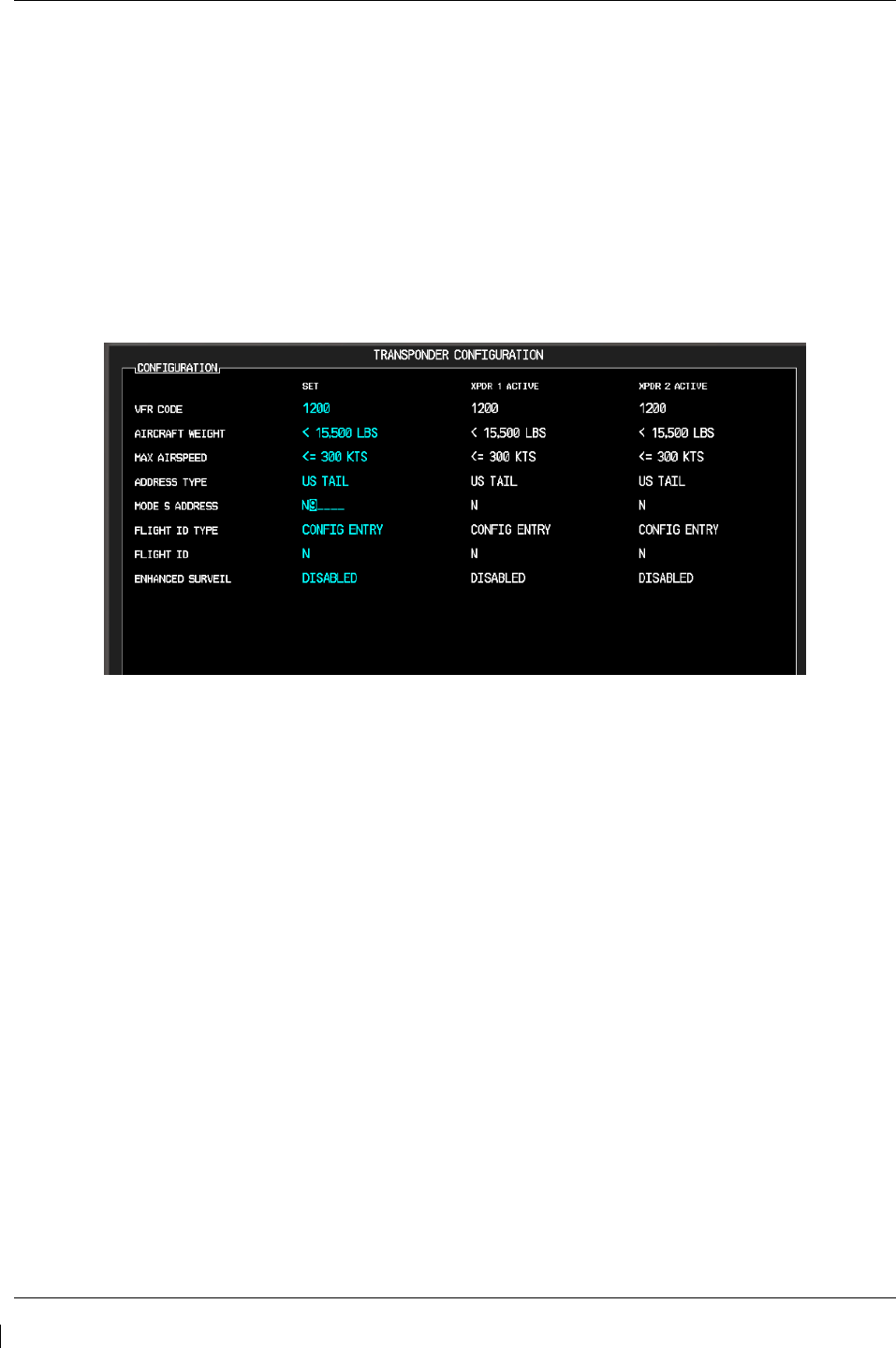
Page 3-52 G1000/GFC700 System Maintenance Manual – C90A/C90GT/C90GTi King Air
Revision G 190-00682-01
3.10 Aircraft Registration Number Entry
If not applied, apply power to the G1000 system.
1. With PFD1 in configuration mode, select the GTX page group, then select the TRANSPONDER
CONFIGURATION page on PFD1.
2. Select or verify selected, XPDR1 is in the SELECT TRANSPONDER window.
3. Ensure that the ‘ADDRESS TYPE’ is ‘US TAIL’ under the ‘SET’ and ‘ACTIVE’ columns.
4. Activate the cursor and highlight the ‘ADDRESS’ field. Use the small/large FMS knobs to enter
the aircraft registration number.
Figure 3-24. Aircraft Registration
5. Once the correct registration number is entered, press the ENT key. The transponders are
configured.
6. Press the ENT key on PFD1 to acknowledge prompt.
7. Verify FLIGHT ID TYPE = SAME AS TAIL under SET and ACTIVE columns.
8. After completing transponder configuration, deactivate the cursor.
3.11 Splash Screen Loading
When all software and configuration has been loaded, the splash screens must be loaded to all display
units (PFD1, PFD2 and MFD).
1. If not applied, apply power to the G1000 system.
2. Remove power from PFD1, PFD2 and MFD by opening the PFD1 PRI/SEC, PFD2 and MFD
circuit breakers.
3. Insert the software loader card in the upper slot of PFD2.
4. Apply power to PFD2.
5. When prompted to update system files, press the NO softkey.
6. When prompted to update splash screen files, press the YES softkey.
7. Remove the loader card from PFD2 and insert it into the upper slot of the MFD.

G1000/GFC700 System Maintenance Manual – C90A/C90GT/C90GTi King Air Page 3-53
190-00682-01 Revision G
8. Apply power to the MFD and repeat steps 5 and 6.
9. Remove the loader card from the MFD and insert it into the upper slot of PFD1.
10. Apply power to PFD1 and repeat steps 5 and 6.
11. Cycle power to the MFD and splash screen will be present.
NOTE
Any time software and/or configuration is loaded to the system, the splash
screens may need to be reloaded to all three display units.
3.12 Clearing Default User Settings
1. Remove power from PFD1, PFD2 and MFD by pulling the PFD1 PRI, PFD1 SEC, PFD2 and
MFD circuit breakers.
2. While holding the CLR button on PFD1, reset PFD1 PRI and PFD1 SEC circuit breakers.
3. While holding the CLR button on PFD 2, reset the PFD2 circuit breaker.
4. While holding the second key from the right side of the MFD (beginning on the right side of the
MFD, count 2 keys to the left), reset the MFD circuit breaker.
5. When prompted to clear user settings, select the YES softkey on each unit.

Page 3-54 G1000/GFC700 System Maintenance Manual – C90A/C90GT/C90GTi King Air
Revision G 190-00682-01
This page intentionally left blank

G1000/GFC700 System Maintenance Manual – C90A/C90GT/C90GTi King Air Page 4-1
190-00682-01 Revision G
4 Instructions for Continued Airworthiness
4.1 Airworthiness Limitations
The G1000 Integrated Flight Deck including the GFC 700 AFCS is airworthy when installed, configured,
and maintained in accordance with this section.
The G1000 and GFC 700 systems possess the following maintenance airworthiness limitations: The
intervals for the airworthiness limitations are shown in maximum number of hours between checks, as
required for certification. Table 4-1 aligns these requirements with the King Air Phase Inspection
Program. These limitations were derived from the certification data.
GFC 700 Limitations:
•
Every 220 hours, perform a check to verify that flaps-in-motion discrete inputs function
correctly. Refer to Table 4-1.
•
Every 420 hours, perform a GSM 85A slip clutch check (if GSM 85A is applicable) to
verify proper operation. Refer to Table 4-1.
•
Every 3000 hours, perform a GSM 86 clutch check (if GSM 86 is applicable) to verify
proper operation. Refer to Table 4-1.
•
Every 1000 hours, perform a servo current display check of the pitch, roll, and yaw servo.
Refer to Table 4-1.
•
Every 220 hours, perform a trim annunciator check to verify proper operation. Refer to
Table 4-1.
G1000 Limitations:
• Every 220 hours, perform a G1000 redundant connections check. Refer to Table 4-1.
•
Every 220 hours, perform a G1000 cooling system electrical check. Refer to Table 4-1.
•
Every 220 hours, perform a nose avionics compartment fans operational check. Refer to
Table 4-1.
•
Every 220 hours, perform an instrument panel fans operational check. Refer to Table
4-1.
•
Every 820 hours, perform an engine data check. Refer to Table 4-1.
•
Every 820 hours, perform a G1000 miscompare check. Refer to Table 4-1.
Other Limitations:
•
Every 220 hours, check for proper function of the internal lighting of the standby attitude
indicator (Mid-Continent P/N 4200-10), standby altimeter (Thommen P/N
3A43.22.35F.28.1.FU) and standby airspeed indicator (Thommen P/N
5A58.22.26K.28.1) as well as the proper power availability to the standby attitude
indicator and standby altimeter vibrator by performing the Standby Instrument Electrical
Power Checks. Refer to Table 4-1.
•
Every 200 hours or 6 Calendar Months (whichever occurs first), perform an Emergency
Battery Check of the L-3 PS-835(C or D Model) Emergency Battery. Refer to Table 4-1.

G1000/GFC700 System Maintenance Manual – C90A/C90GT/C90GTi King Air Page 4-3
190-00682-01 Revision G
4.2 Servicing Information
G1000 LRU maintenance is ‘on condition’ only. No component-level overhaul is required for this type
design change.
4.2.1 On Condition Servicing
‘On Condition’ replacement and/or servicing should occur when an item exhibits conditions, symptoms,
and/or abnormalities defined in Section 5 of this manual. Replacement and/or servicing should be made
only after the technician troubleshoots the system to the extent determined necessary by using the
guidance in this manual along with common avionics maintenance practices.
IMPORTANT!
It is impossible to provide guidance for every conceivable failure scenario within the
scope of this manual. Every effort has been made to provide comprehensive
guidance for possible failures. The information in this document should always be
combined with common sense and a thorough knowledge of the system. Use sound
avionics maintenance practices when working around or on G1000 equipment.
The remainder of this document is organized in the following fashion:
•
Section 4.3 lists maintenance requirements related to the G1000 system.
•
Section 6 gives instructions regarding the removal and replacement of physical
G1000 equipment and parts.
•
Section 7 gives configuration and testing instructions to be accomplished if G1000
equipment or parts are removed or replaced.
•
Section 8 specifies system return-to-service procedures.
The beginning of Section 6 provides instructions to check the software part number and version of each
LRU before removing a unit. Procedures in Section 7 require the same check after LRU replacement and
software loading.
IMPORTANT!
All structural repairs associated with this installation are to be addressed in
accordance with the Hawker Beechcraft Structural Inspection and Repair Manual
listed in Table 1-3.

Page 4-4 G1000/GFC700 System Maintenance Manual – C90A/C90GT/C90GTi King Air
Revision G 190-00682-01
4.2.2 Required Tools
The following tools are needed to perform maintenance tasks on G1000 equipment:
•
Calibrated Milli-ohm meter, OR
Agilent 34410A Ammeter or equivalent
Fluke 187 Voltmeter or equivalent
Power Supply capable of providing 1 amp current
•
#2 Non-Magnetic Phillips Screwdriver
•
3/32” Hex tool
•
Calibrated digital level (Required for AHRS ‘Procedure A’ Calibration)
•
Calibrated VHF NAV/COM/ILS ramp tester or equivalent
•
Calibrated transponder ramp tester or equivalent
•
Calibrated pitot/static ramp tester
•
Outdoor line-of-site to GPS satellite signals or GPS indoor repeater
•
Headset/microphone
•
Ground Power Unit (Capable of supplying 28 Vdc)
•
Calibrated Flight Control Cable Tension Meter or equivalent
•
Servo Mount Slip Clutch Adjustment Tool – Garmin P/N T10-00110-01 and a 2 Amp, 24 V, DC
Power Supply
•
Calibrated torque wrench capable of measuring 0 – 70 in/lbs
•
Standard sockets & wrenches (3/8”, 9/16”, and 13/16”)
•
Calibrated digital thermometer suitable for measuring ambient temperature
•
Laptop with RS232 emulation software
•
M22885/108T8234 extraction tool
•
An 0.060” 6-Spline wrench
•
WX-PA portable analyzer kit (If Stormscope is installed)
G1000/GFC700 System Maintenance Manual – C90A/C90GT/C90GTi King Air Page 4-5
190-00682-01 Revision G
4.3 Maintenance Intervals
Table 4-1 shows systems and items, installed by this STC, which must undergo tests or checks at specific
intervals. If the interval is shown to be in flight time as well as calendar months, the first interval reached
should be used as the limit.
The inspection time tables used are aligned with the existing maintenance phase intervals used in the
current King Air Model 90 Series Maintenance Manual. A complete inspection cycle for the King Air
C90 is 800 hours or 24 calendar months, divided into the following four phases:
• Inspection Phase 1: To be performed at 200 hours and every 800 hours thereafter.
• Inspection Phase 2: To be performed at 400 hours and every 800 hours thereafter.
• Inspection Phase 3: To be performed at 600 hours and every 800 hours thereafter.
• Inspection Phase 4: To be performed at 800 hours and every 800 hours thereafter.
Those inspections that are based on flight time, calendar elapsed time or cycles shall have specific
intervals stated in Table 4-1.
IMPORTANT!
As allowed in the King Air Model 90 Series Maintenance Manual, a tolerance of +/-
20 hours for all phase inspections. For tolerances on calendar months, refer to the
King Air Model 90 Series Maintenance Manual listed in Table 1-2.
The intention of Garmin is to align this maintenance program as best possible with the existing King Air
C90 inspection program. For a complete description of the King Air inspection program, refer to the
King Air Model 90 Series Maintenance Manual listed in Table 1-2.
Table 4-1. Maintenance Intervals
Item Description/Procedure
Manual
Section No. Interval
G1000/GFC700 Equipment
G1000/GFC700
System Visual
Inspections
Complete Visual Inspection of GWX 68
Equipment and Wiring located in Nose
Section
4.4
(Table 4-3)
Phase 4
Complete Visual Inspection of
G1000/GFC700 Equipment and Wiring
located in Nose Avionics Compartment
4.4
(
Table 4-4
)
Phase 4
Complete Visual Inspection of
G1000/GFC700 Equipment and Wiring
located in Pilot’s Compartment
4.4
(
Table 4-5
)
Phase 3
Complete Visual Inspection of
G1000/GFC700 Equipment and Wiring
located on and behind Instrument Panel
4.4
(
Table 4-6
)
Phase 3
Complete Visual Inspection of
G1000/GFC700 Equipment and Wiring
located in Cabin
4.4
(
Table 4-7
)
Phase 3
Complete Visual Inspection of
G1000/GFC700 Equipment and Wiring
located in Rear Fuselage and Empennage
4.4
(
Table 4-8
)
Phase 4

Page 4-6 G1000/GFC700 System Maintenance Manual – C90A/C90GT/C90GTi King Air
Revision G 190-00682-01
Item Description/Procedure
Manual
Section No. Interval
GFC700 Periodic
Check
Verify proper operation of the GFC700 by
performing the following:
Pre-Flight Test
AFCS Switch Checks
Autopilot Operation Checks
8.2.1,
8.2.2,
8.2.5
Phase 2 and 4
TAWS Functional
Check Periodic TAWS function check 7.15 Phase 4
GDU 1040A PFD
(Qty 2) Removal & Replacement 6.1 On Condition
GDU 1500 MFD Removal & Replacement 6.1 On Condition
GMA 1347D (Qty 2)
Removal & Replacement 6.2 On Condition
GMA 1347D Test 7.2.1 Phase 2 and 4
Landing Gear Aural Alert and XM Audio
Suppression Test 7.2.2 Phase 2 and 4
XM Audio Suppression Check 7.2.3 or 7.2.4 Phase 2 and 4
GIA 63W IAU (Qty 2)
Removal & Replacement
6.3
On Condition
GEA 71 EAU (Qty 2) 6.4
GTX 33 Transponder
(Qty 2)
Removal & Replacement 6.5 On Condition
Test according to Title 14 CFR §§ 91.411
and 91.413 as well as Part 43 Appendix F. 7.5 24 Calendar Months
GDC 74B (Qty 2)
Removal & Replacement 6.6 On Condition
Test according to Title 14 CFR § 91.411 and
Part 43 Appendix E. 7.6 24 Calendar Months
GRS 77 AHRS (Qty
2)
Removal & Replacement 6.8
On Condition
Magnetic variation database update. 4.6
GMU 44
Magnetometer (Qty 2)
Removal & Replacement
6.9
GDL 69A 6.10
GWX 68 6.15
GMC 710 6.14
GCU 475 6.13
G1000 Cooling
System Electrical
Check*
Verify the operation of the fan power and
fan speed monitoring circuits for GIA1
Fan, GIA2 fan, PFD1 fan, MFD fan and
PFD2 fan and fan fail messages
8.1.4 220 hours max
Nose Avionics
Compartment Fans
Operational Check*
Functional test of the GIA1 and GIA2
ported fans. Verify airflow from all fan
ports
4.14 220 hours max
Instrument Panel
Fans Operational
Check*
Functional test of the PFD1, MFD and
PFD2 cooling fans. Verify airflow from
each fan
4.15 220 hours max
*
Denotes Airworthiness Limitation Maintenance Requirement (See Section 4.1)

G1000/GFC700 System Maintenance Manual – C90A/C90GT/C90GTi King Air Page 4-7
190-00682-01 Revision G
Item Description/Procedure
Manual
Section No. Interval
G1000 Redundant
Connection Check*
Verify PRI and SEC power sources for
PFD 1, GIA 1, GRS 1, GDC 1
Verify secondary paths for AHRS, ADC,
engine parameters and GPS data
Verify the operation of PFD and MFD
Ethernet connections
Verify ARINC connection between ADC1
and MFD and between GRS1 and MFD
Verify DISPLAY BACKUP button function
4.10 220 hours max
Engine Data Check * Verify engine data is available and
accurate 4.11 820 hours max
Trim Annunciator
Check*
Verify trim annunciators function
properly 4.12 220 hours max
G1000 Miscompare
Check*
Verify AHRS, airspeed and altitude
miscompare monitors function properly 4.13 820 hours max
G1000 Alerts
Check for and troubleshoot any alerts
provided in the alert window per the
referenced manual section
5 On Condition
GPS/WAAS
Antennas
Removal & Replacement
Refer to Master Drawing List, listed in Table
1-2, for installation drawings.
6.18 On Condition
Flaps-in-motion
Discrete Input
Check*
Test the Flaps-in-motion discrete inputs
to the G1000 to verify proper operation. 4.8 220 hours max
GSA 81 and GSA 80
Servos (all)
Removal & Replacement.
Refer to the servo install drawings listed in
Master Drawing List, listed in Table 1-2.
6.11 On Condition
Clean and apply grease to output gears. 4.7 Phase 4
GSM 85A/86 Servo
Mounts (all)
Removal & Replacement.
Refer to the servo install drawings listed in
Master Drawing List, listed in Table 1-2.
6.12 On Condition
GSM 86 Clutch
Torque Check*
Verify that the pitch, roll and pitch trim
GSM 86 clutch torque values are within
acceptable limits.
4.9 3,000 hours max
Servo Current
Display Check*
Verify servo load cell integrity by
monitoring servo current at each axis 4.9 1,000 hours max
GSM 85A Servo
Mount Slip Clutch
Torque Check
*
Verify that the pitch, roll, yaw and pitch
trim GSM 85A slip clutches are within
acceptable limits.
4.9 420 hours max
G1000 Accessories
Configuration Module
Replacement (Qty 7) Removal & Replacement. 6.16
On Condition
GEA 71 Backshell
Thermocouple (Qty 2) Removal & Replacement. 6.17
GTP 59 OAT Probe
(Qty 2) Removal & Replacement. 6.7
*
Denotes Airworthiness Limitation Maintenance Requirement (See Section 4.1)

Page 4-8 G1000/GFC700 System Maintenance Manual – C90A/C90GT/C90GTi King Air
Revision G 190-00682-01
Item Description/Procedure
Manual
Section No. Interval
PFD, MFD, and GIA
Cooling Fans (Qty 5)
Removal & Replacement
Refer to Master Drawing List, listed in Table
1-2, for installation drawings.
N/A
G1000 Lightning Protection
Electrical Bonding
Test
Perform the Phase 3 electrical bonding
resistance check of G1000 equipment 4.5.3 Phase 3
Perform the Phase 4 electrical bonding
resistance check of G1000 equipment 4.5.4 Phase 4
Lightning Strike to
GTP 59 OAT Probe
or Antenna
Actual or Suspected
Inspect the antenna/probe and surrounding
installation per Table 4-9.
4.4
On Condition
Engine/Airframe Sensors
ITT Thermocouple
Cable (Qty 2)
Removal & Replacement:
Refer to King Air Model 90 Series
Maintenance Manual listed in Table 1-2.
N/A On Condition
Oil Pressure Sensor
(Qty 2)
Oil Temperature
Sensor (Qty 2)
Torque Transmitter
(Qty 2)
Fuel Flow Transmitter
(Qty 2)
Removal & Replacement:
Refer to King Air Model 90 Series
Maintenance Manual listed in Table 1-2.
N/A
On Condition
Prop Tachometer
(Qty 2)
Engine Speed
Tachometer (Qty 2)
Engine Signal
Conditioners (Qty 2)
Removal & Replacement
6.19
Aerospace Optics
Annunciator – Prop
Sync
6.21
PC920 Conditioner (if
added by this STC) 6.20
Other Equipment
Thommen Airspeed
Indicator - Standby Removal & Replacement 6.23 On Condition
Thommen Altimeter –
Standby
Removal & Replacement 6.24 On Condition
Test according to 14 CFR 91.411 and
Part 43 Appendix E. N/A 24 Calendar Months
Mid-Continent
Attitude Indicator –
Standby
Removal & Replacement 6.25 On Condition
L-3 PS-835(C or D
Emergency Battery
Removal & Replacement 6.22 On Condition
Capacity test of standby battery 4.16.2 12 Calendar Months
G1000/GFC700 System Maintenance Manual – C90A/C90GT/C90GTi King Air Page 4-9
190-00682-01 Revision G
Item Description/Procedure
Manual
Section No. Interval
Emergency Battery
Check*
Verify the emergency battery is being
charged 4.16.1
200 hours max or
6 Calendar Months
(whichever first)
Standby Instrument
Electrical Power
Checks
*
Verify STBY ATT & STBY ALT vibrator
operate and STBY ATT, STBY ALT &
STBY A/S illumination function on either
aircraft power or standby battery power
(standby compass checked during
existing maintenance)
8.1.5 220 hours max
Aerospace Optics
Annunciator –
Standby Battery
Removal & Replacement 6.21
On Condition
Northern Airborne
Speaker Amplifier (if
added by this STC)
Removal & Replacement:
Refer to King Air Model 90 Series
Maintenance Manual listed in Table 1-2.
N/A
4.3.1 Discontinued Maintenance
Table 4-2 shows a list of inspections and tests that are listed in the King Air Model 90 Series Maintenance
Manual, but may be no longer required post incorporation of this STC. It is the responsibility of the
installer to ensure that there are no post factory installations that would require these checks to remain.
Table 4-2. Discontinued Maintenance Intervals
Item
Description/Procedure
Manual
Interval
AC Inverter Operational Check Phase Inspections Phases 1 - 4
Engine Torque
Indicating System** Torque Indicator Re-calibration CenTex STC
SA10339SC 5,000 hours
** Engine Torque Indicating System as installed by CenTex STC SA10339SC includes both an
indicator and a transducer. The indicator is removed per this STC (SA01456WI-D); the
transducer remains in the aircraft and the existing maintenance requirements for the transducer
are still applicable.
IMPORTANT!
For installed equipment not listed in this maintenance manual, use the inspection
procedures set forth in Chapter 05 of the King Air Model 90 Series Maintenance
Manual, or other appropriate maintenance manual, as the requirements set forth by
those manuals are still applicable. The requirements set forth by this document
take precedence over those set forth by the King Air Model 90 Series Maintenance
Manual, or other appropriate maintenance manual, in cases where the requirements
conflict.
*
Denotes Airworthiness Limitation Maintenance Requirement (See Section 4.1)

Page 4-10 G1000/GFC700 System Maintenance Manual – C90A/C90GT/C90GTi King Air
Revision G 190-00682-01
4.4 Visual Inspection
Perform a visual inspection in accordance with requirements in Table 4-1. Check for corrosion, damage,
or other defects for each of the items listed in Table 4-3 through Table 4-8. Replace any damaged parts as
required. Inspection may require the temporary removal of a unit or units to gain access to connectors.
Follow guidance in Section 6 for equipment removal and replacement. Refer to the King Air Model 90
Series Maintenance Manual listed in Table 1-2 for instructions on removing any access panels.
NOTE
It is recommended that the Phase 3 and Phase 4 electrical bonding checks contained in section 4.5 are
conducted after the Phase 3 and 4 visual inspections while access to these zones is still open.
Table 4-3. Nose Section Visual Inspection Procedure
Item
Description/Procedure
Initials
Gain access via the Radome for the following Inspection:
GWX 68
a) Inspect the GWX 68 unit, mount, and connectors for corrosion or other defects.
Check the integrity of the SHIELD BLOCK ground attachments to the harness
connector assembly as well as the integrity of the individual shields and their
attachment.
b) Inspect wire harness for chafing, damage, proper routing of wire bundles and security
of attachment in accordance with AC 43.13-1B, Chapter 11, Section 8, Paragraph
11-96 and the Nose Wire Harness Routing drawing, listed in
Table 1-2.
Table 4-4. Nose Avionics Compartment Visual Inspection Procedure
Item
Description/Procedure
Initials
Gain access via the Nose Equipment Compartment access panel for the following Inspection:
GRS 77 (Qty 2)
a) Inspect the GRS 77 units, racks, and connectors for corrosion or other defects.
Check the integrity of the SHIELD BLOCK ground attachments to the harness
connector assembly as well as the integrity of the individual shields and their
attachment.
GTX 33 (Qty 2)
a) Inspect the GTX 33 units, racks, and connectors for corrosion or other defects.
Check the integrity of the SHIELD BLOCK ground attachments to the harness
connector assembly as well as the integrity of the individual shields and their
attachment.
GIA 63W (Qty 2)
1. Inspect the GIA 63W units, racks, and connectors for corrosion or other defects.
Check the integrity of the SHIELD BLOCK ground attachments to the harness
connector assembly as well as the integrity of the individual shields and their
attachment.
GIA Avionics Fan
(Qty 2)
a) Inspect remote avionics fans and hoses for dirt accumulation and other damage.
Remove excess dirt as required.
LMD Rack and
Modules a) Inspect the LMD rack, modules, and termination for corrosion or other defects.
Nose Wiring
Harness
a) Inspect bulkhead connectors for security of attachment, corrosion or other defects.
b) Inspect wire and coax for chafing, damage, proper routing of wire bundles and
security of attachment in accordance with AC 43.13-1B, Chapter 11, Section 8,
Paragraph 11-96 and the Nose Wire Harness Routing drawing, listed in Table 1-2. .
Pay particular attention to possible areas of chaffing such as the middle shelf feed-
through hole, wheel well protrusion etc.
c) Inspect Ground blocks for security of attachment, corrosion or other defects.
d) Ensure all connectors are securely fastened.

G1000/GFC700 System Maintenance Manual – C90A/C90GT/C90GTi King Air Page 4-11
190-00682-01 Revision G
Table 4-5. Pilot’s Compartment Visual Inspection Procedure
Item
Description/Procedure
Initials
Locate equipment in the aft pedestal for the following inspection:
GCU 475
a) Inspect the GCU 475 unit and connector for corrosion or other defects. Check the
integrity of the SHIELD BLOCK ground attachments to the harness connector
assembly as well as the integrity of the individual shields and their attachment.
ADF CTL-62
(relocated by STC)
a) Inspect the CTL-62 unit and connector for corrosion or other defects. Check the
integrity of the SHIELD ground attachments to the harness connector assembly as
well as the integrity of the individual shields and their attachment. Refer also to the
King Air Model 90 Series Maintenance Manual, listed in Table 1-2.
To gain access for the following Inspections, remove pilot and co-pilot seats and cockpit floor panels.
NOTE: The tach-gen filter assemblies, GPN 005-00375-93, are installed underneath the pilot and co-pilot cockpit
floor panels. Caution must be observed when removing floor panels so as not to damage tach-gen filter
harnesses. A connector is installed in each tach-gen filter harness to allow the filter to be disconnected when
removing the floor panel. (The Tach-gen filter assembly is applicable to installations with Sandia ST-26 Tach-Gen
Adapter unit installed by STC SA01456WI-D MDL 005-00375-30, Revision 4 and previously approved revisions.)
Pedestal Wiring
a) Inspect all visible wire harness for chafing, damage, proper routing of wire bundles
and security of attachment in accordance with AC 43.13-1B, Chapter 11, Section 8,
Paragraph 11-96 and the Cabin Wire Harness Routing drawing, listed in Table 1-2.
GTP 59 (Qty 2)
a) Inspect the GTP 59 units and connectors for corrosion or other defects. Check the
integrity of the SHIELD ground attachments to the harness connector assembly as
well as the integrity of the individual shields and their attachment.
b) Inspect wire harness for chafing, damage, proper routing of wire bundles and security
of attachment in accordance with AC 43.13-1B, Chapter 11, Section 8, Paragraph
11-96 and the Cabin Wire Harness Routing drawing, listed in
Table 1-2

Page 4-12 G1000/GFC700 System Maintenance Manual – C90A/C90GT/C90GTi King Air
Revision G 190-00682-01
Table 4-6. Instrument Panel G1000 Equipment Visual Inspection Procedure
Item
Description/Procedure
Initials
Gain access to behind the instrument panel by removing the PFDs and MFD. Gain access to circuit breaker panels by removing
the screws which fasten then edgelit placards to the panels
GDU 1040A PFD
(Qty 2) & GDU 1500
MFD
a) Remove the MFD and PFDs as described in Section 6.
b) Inspect the mounting surface, copper bonding fingers and connector for corrosion,
heavy oxidation, or other damage. Check the integrity of the SHIELD BLOCK ground
attachments to the harness connector assembly as well as the integrity of the
individual shields and their attachment.
c) Inspect the CTL-62 unit and connector for corrosion or other defects. Check the
integrity of the SHIELD ground attachments to the harness connector assembly as
well as the integrity of the individual shields and
their attachment.
Refer also to the
King Air Model 90 Series Maintenance Manual, listed in Table 1-2.
d) Do not reinstall GDUs at this time. GDU cutouts provide access for visual inspections
below.
G1000 Wiring
harness
a) Inspect all instrument panel wire harness for chafing, damage, proper routing of wire
bundles and security of attachment in accordance with AC 43.13-1B, Chapter 11,
Section 8, Paragraph 11-96 and the Cabin Wire Harness Routing drawing, listed in
Table 1-2.
b) Inspect all other exposed G1000 wiring for chafing, damage, proper routing of wire
bundles and security of attachment in accordance with AC 43.13-1B, Chapter 11,
Section 8, Paragraph 11-96 and the Cabin Wire Harness Routing drawing, listed in
Table 1-2.
c) Inspect all fwd bulkhead connectors for security of attachment
GDC 74B Air Data
Computer (Qty 2)
a) Visually inspect each GDC 74B unit, mount, and connector for corrosion or other
defects. Check the integrity of the SHIELD BLOCK ground attachments to the
harness connector assembly as well as the integrity of the individual shields and their
attachment.
b) Visually inspect the pitot/static plumbing and ensure it is secure and in good
condition.
GEA 71 Engine/
Airframe Unit (Qty 2)
a) Inspect the GEA 71 unit, rack, and connectors for corrosion or other defects. Check
the integrity of the SHIELD BLOCK ground attachments to the harness connector
assembly as well as the integrity of the individual shields and their attachment.
GMA 1347D (Qty 2)
a) Inspect the GMA 1347D unit, rack and connectors for corrosion or other defects.
Check the integrity of the SHIELD BLOCK ground attachments to the harness
connector assembly as well as the integrity of the individual shields and their
attachment.
PFD and MFD Fans
(Qty 3)
a) Inspect fans for accumulation of dirt and other damage. Remove excess dirt as
required.
GDL 69A
a) Inspect the GDL 69A unit, rack, and connectors for corrosion or other defects. Check
the integrity of the SHIELD BLOCK ground attachments to the harness connector
assembly as well as the integrity of the individual shields and their attachment.
GMC 710
a) Inspect the GMC 710 unit, mount, and connectors for corrosion or other defects.
Check the integrity of the SHIELD BLOCK ground attachments to the harness
connector assembly as well as the integrity of the individual shields and their
attachment.
Senior Aerospace
PC920 Signal Cond.
a) Inspect the PC920 unit, mount, and connectors for corrosion or other defects.
NOTE: Applicable only to STC SA01456WI-D, MDL 005-00375-30, Revision 4 and
previously approved revisions.
Sandia Aerospace
ST26 Adapter(Qty 2)
a) Inspect the ST26 unit, mount, and connectors for corrosion or other defects
NOTE: Applicable only to STC SA01456WI-D, MDL Revision 4 and previously approved
revisions.
VMI Signal
Conditioner (Qty 2)
a) Inspect the signal conditioner unit, mount, and connectors for corrosion or other
defects.
NOTE: Applicable only to STC SA01456WI-D, MDL 005-00375-30, Revision 5 and
subsequent approved revisions.

G1000/GFC700 System Maintenance Manual – C90A/C90GT/C90GTi King Air Page 4-13
190-00682-01 Revision G
Item
Description/Procedure
Initials
Mid-Continent
Standby Attitude Ind.
a) Inspect the standby attitude indicator unit and connector for corrosion or other
defects.
Thommen Standby
Airspeed Ind.
a) Inspect the standby airspeed indicator unit and connector for corrosion or other
defects
.
b) Visually inspect the plumbing and harness connector assembly, and ensure it is
secure and in good condition.
Thommen Standby
Altimeter
a) Inspect the standby altimeter indicator unit and connector for corrosion or other
defects
.
b) Visually inspect the plumbing and harness connector assembly, and ensure it is
secure and in good condition.
Circuit Breaker
Panels
a) Inspect circuit breaker panel wiring and circuit breakers for chafing, damage, other
defects and proper routing of wire bundles and security of attachment in accordance
with AC 43.13-1B, Chapter 11, Section 8, Paragraph 11-96, the appropriate Circuit
Breaker Panel Modification drawing, listed in Table 1-2, and the Cabin Wire Harness
Routing drawing, listed in Table 1-2. Pay particular attention to possible areas of
chaffing.
b) Inspect edgelit overlay panels for damage or defect.
c) Reinstall the circuit breaker edgelit overlays to the circuit breaker panels.
a) Reinstall the MFD and PFDs as described in Section 6.
b) Reinstall the circuit breaker edgelit placards to the circuit breaker panels.
Table 4-7. Cabin Area Visual Inspection Procedure
Item
Description/Procedure
Initials
To gain access for the following Inspections, remove floorboard in cabin at FS 185.00
Cabin Wiring
Harness
a) Inspect all exposed wire harness for chafing, damage, proper routing of wire
bundles and security of attachment in accordance with AC 43.13-1B,
Chapter 11, Section 8, Paragraph 11-96 and the Cabin Wire Harness Routing
drawing, listed in
Table 1-2
.
GFC 700 Equipment
a) Using a flashlight, inspect the servo, servo mount, connectors, support
structures, and control cables to ensure that no corrosion, chaffing, cracks, or
other defects exist.
b) Have an assistant manually move the control surfaces from stop to stop and
visually observe the servo, and control cabling/chain. Ensure there is no binding
in the control cabling or chain, and that the capstan/sprocket rotates freely.
c) Check the servo control cables in accordance with AC 43.13-1B, Chapter 7,
Section 8, Paragraph 7-149 to ensure no fraying, corrosion, or other damage
exists. If the condition of the cable is questionable, replace it with a new one.
d) Check the tension on the control cables. Refer to the Roll Servo Install drawing,
listed in Table 1-2,
for cable tension specifications:
e) Ensure that each cable is correctly attached to the clamps.
f) Follow recommended checks for checking main control cables,
following the instructions in Chapter 27, Flight Controls, of the King Air
Model 90 Series Maintenance Manual.
g) Replace the access panels if no other maintenance is to be performed.

Page 4-14 G1000/GFC700 System Maintenance Manual – C90A/C90GT/C90GTi King Air
Revision G 190-00682-01
Table 4-8. Rear Fuselage and Empennage Visual Inspection Procedure
Item
Description/Procedure
Initials
To gain access for the following Inspections, refer to the servo installation drawings and the King Air Model 90
Series Maintenance Manual, listed in Table 1-2.
Tail Wiring Harness
a) Inspect all exposed wire harness for chafing, damage, proper routing of wire
bundles and security of attachment in accordance with AC 43.13-1B,
Chapter 11, Section 8, Paragraph 11-96 and the Tail Wire Harness Routing
drawing, listed in
Table 1-2
.
b) Verify security of aft bulkhead connectors
GFC 700 Equipment
a) Using a flashlight, inspect the servos, servo mounts, connectors, support
structures, and control cables to ensure that no corrosion, chaffing, cracks, or
other defects exist.
b) Have an assistant manually move the control surfaces and elevator trim wheel
from stop to stop and visually observe the corresponding servo and control
cabling/chain. Ensure there is no binding in the control cabling or chain, and that
the capstan/sprocket rotates freely.
c) For GSM 86 servo gearboxes (if installed), check that the retaining bolt for the
slip clutch cartridge is not damaged or loose.
d) Check the servo control cables in accordance with AC 43.13-1B, Chapter 7,
Section 8, Paragraph 7-149 to ensure no fraying, corrosion, or other damage
exists. If the condition of the cable is questionable, replace it with a new one.
e) Check the tension on the control cables. Refer to the respective servo
installation drawing listed in Table 1-2 for cable tension specifications
f) Ensure that each cable is correctly attached to the clamps.
g) Follow recommended checks for checking main control cables,
following the instructions in Chapter 27, Flight Controls, of the King Air
Model 90 Series Maintenance Manual, listed in Table 1-2.
h) Replace the access panels if no other maintenance is to be performed.
The GMU 44 units are mounted in the vertical tail. To gain access, remove service panel in tail. Refer to King Air
Model 90 Series Maintenance Manual, listed in Table 1-2, for removal instructions.
GMU 44 (Qty 2)
a) For each GMU 44, do the following:
b) Remove the three Phillips screws holding the GMU access plate to the mounting
bracket. Be sure to use a non-magnetic screwdriver to avoid harming the GMU.
c) Carefully lower the assembly and inspect the GMU 44 and mounting plate.
d) Inspect the mounting hardware and GMU 44 for corrosion or other damage.
e) Inspect the GMU wiring and ensure no chaffing, wear, or other damage exists in
accordance with AC 43.13-1B, Chapter 11, Section 8, Paragraph 11-96 and the Tail
Wire Harness Routing drawing, listed in
Table 1-2.
Pay particular attention to
possible areas of chaffing.
f) Reinstall the GMU 44.
Table 4-9, Lightning Strike Inspection Procedure
Item
Description/Procedure
Initials
GTP 59 OAT Probe
or Antenna
a) A post lightning strike inspection must be done for a suspected or actual lightning
strike to antennas or the OAT probes. Inspect antenna/probe and surrounding
installation to ensure that there is no structural damage around the areas where
lightning may have attached. If there is visible sign of damage to the probe or
antenna, then it should be replaced per Section 6.7. Refer to the Hawker Beechcraft
Structural Inspection and Repair Manual listed in Table 1-3 for any aircraft structural
repairs.
Nose Avionics
Compartment Fans
a) A post lightning strike operational check of the GIA1 and GIA2 ported fans must be
done. Verify airflow from all fan ports per Section 4.14. Verify fan power and the
speed monitoring circuit of the GIA1 and GIA2 fans per Section 8.1.4. If replacement
of the fan(s) is required, refer to Section 6.26.

G1000/GFC700 System Maintenance Manual – C90A/C90GT/C90GTi King Air Page 4-15
190-00682-01 Revision G
IMPORTANT!
For installed equipment not listed in this maintenance manual, use the inspection
procedures set forth in Chapter 05 of the King Air Model 90 Series Maintenance
Manual, or other appropriate maintenance manual, as the requirements set forth by
those manuals are still applicable. The requirements set forth by this document
take precedence over those set forth by the King Air Model 90 Series Maintenance
Manual, or other appropriate maintenance manual, in cases where the requirements
conflict.
4.5 Electrical Bonding Test
The following bonding test is provided for G1000-equipped C90A/C90GT/C90GTi King Air aircraft as a
requirement beyond what is given in the aircraft maintenance manual. The electrical bonding checks are
split into two tests, Phase 3 Electrical Bonding Test and Phase 4 Electrical bonding test. This places the
bonding test requirement for each G1000 LRU in the same phase as the visual inspection of that zone to
minimize access requirements.
4.5.1 Requirements
All G1000 equipment must be installed. Gain access for the procedure listed below in Section 4.5.3 as
required and in accordance with the King Air Model 90 Series Maintenance Manual. It is recommended
that these tests are conducted after visual inspection of the zone to minimize access requirements.
4.5.2 Test Equipment
A milli-ohm meter and Kelvin probes are recommended for this test. However, a standard voltmeter,
power supply with adjustable current limit, and ammeter may be substituted. The following procedure is
written using the voltmeter, power supply and ammeter. All test equipment must have valid calibration
records.
4.5.3 Phase 3 Electrical Bonding Procedure
1. Connect the positive lead of the power supply to the engine compartment grounding bracket (battery
negative connection to the airframe). Connect/touch the positive lead of the voltmeter to the same
point.
NOTE
Ensure that the voltmeter and power supply probes do not touch, so as not to induce
contact resistance.
2. Touch negative lead of power supply to each of the test points listed while performing Step 3. At
each point, configure the power supply to produce 1 amp before measuring voltage. (Use an ammeter
to ensure current is within 1 amp ±100 milli-amp at each point).
3. Set the voltmeter to measure milli-volts and null the reading. Measure the voltage from the engine
grounding bracket (step 1) to each of the following points and record the voltage. (Perform Step 2 at
each point to ensure that 1 amp ±100 milli-amp is present before measuring)

Page 4-16 G1000/GFC700 System Maintenance Manual – C90A/C90GT/C90GTi King Air
Revision G 190-00682-01
Pilot Compartment
• Top metal case of PFD 1: __________ milli-volts
• Top metal case of PFD 2: __________ milli-volts
• Top metal case of MFD: __________ milli-volts
• Top metal case of GMA 1347D #1: __________ milli-volts
• Top metal case of GMA 1347D #2: __________ milli-volts
• Top metal case of GCU 475: __________ milli-volts
• Top metal case of GMC 710: __________ milli-volts
• GEA 71 #1 body: __________ milli-volts
• GEA 71 #2 body: __________ milli-volts
• GDC 74B #1 body: __________ milli-volts
• GDC 74B #2 body: __________ milli-volts
• OAT 1 Probe base nut (inside fuselage): __________ milli-volts
• OAT 2 Probe base nut (inside fuselage): __________ milli-volts
• GDL 69A body: __________ milli-volts
• Engine Signal Conditioner #1 near mounting holes of case: __________ milli-volts
• Engine Signal Conditioner #2 near mounting holes of case: __________ milli-volts
• PC920 Fuel Flow Signal Conditioner (
if installed
) near mounting holes of case: __ ___ milli-volts
• PFD1 Cooling fan metal base: __________ milli-volts
• PFD2 Cooling fan metal base: __________ milli-volts
• MFD Cooling fan metal base: __________ milli-volts
Cabin Compartment
• GSA 80 (Roll) Servo body: __________ milli-volts
Ensure that at each PFD or MFD test point, no more than 20 milli-volts (20 mΩ) are present. Ensure that
at each other test point, no more than 2.5 milli-volts (2.5 mΩ) are present. In this case, voltage is
equivalent to resistance (Ω), given that precisely 1 amp reference current is present.
TIP: If 1 amp reference current cannot be maintained, note the difference between the attainable current
and 1 amp reference current. Calculate the percentage difference and apply this to the voltage reading to
obtain the equivalent resistance. Example: If the measured current is 1.2 amps, (20% high from the target
1 amp current), then the allowable voltage measurement would be 20% high, 2.5 milli-volts would now
be 3.0 milli-volts.

G1000/GFC700 System Maintenance Manual – C90A/C90GT/C90GTi King Air Page 4-17
190-00682-01 Revision G
4.5.4 Phase 4 Electrical Bonding Procedure
1. Connect the positive lead of the power supply to the engine compartment grounding bracket (battery
negative connection to the airframe). Connect/touch the positive lead of the voltmeter to the same
point.
NOTE
Ensure that the voltmeter and power supply probes do not touch, so as not to induce
contact resistance.
2. Touch negative lead of power supply to each of the test points listed while performing Step 3. At
each point, configure the power supply to produce 1 amp before measuring voltage. (Use an ammeter
to ensure current is within 1 amp ±100 milli-amp at each point).
3. Set the voltmeter to measure milli-volts and null the reading. Measure the voltage from the engine
grounding bracket (step 1) to each of the following points and record the voltage. (Perform Step 2 at
each point to ensure that 1 amp ±100 milli-amp is present before measuring)
Nose Section
• GWX 68 body: __________ milli-volts
Nose Avionics Compartment
• GIA 1 top: __________ milli-volts
• GIA 2 top: __________ milli-volts
• GTX 33 #1 top: __________ milli-volts
• GTX 33 #2 top: __________ milli-volts
• GRS 77 #1 metal base: __________ milli-volts
• GRS 77 #2 metal base: __________ milli-volts
• Standby battery: __________ milli-volts (may be installed in rear fuselage)
Rear Fuselage and Empennage
• GMU 44 #1 metal base: __________ milli-volts
• GMU 44 #2 metal base: __________ milli-volts
• GSA 80 (Pitch) Servo body: __________ milli-volts
• GSA 81 (Pitch Trim) Servo body: __________ milli-volts
• GSA 80 (Yaw) Servo body: __________ milli-volts
TIP: If 1 amp reference current cannot be maintained, note the difference between the attainable current
and 1 amp reference current. Calculate the percentage difference and apply this to the voltage reading to
obtain the equivalent resistance. Example: If the measured current is 1.2 amps, (20% high from the target
1 amp current), then the allowable voltage measurement would be 20% high, 2.5 milli-volts would now
be 3.0 milli-volts.
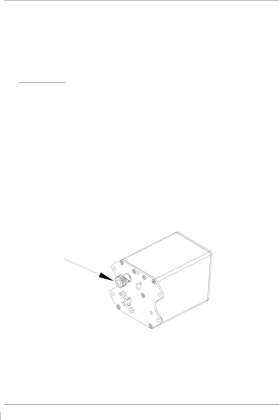
Page 4-18 G1000/GFC700 System Maintenance Manual – C90A/C90GT/C90GTi King Air
Revision G 190-00682-01
4.6 GRS 77 Earth Magnetic Field Updates
The GRS 77 utilizes an Earth magnetic field model which is updated once every five years. The update is
expected to be available from Garmin in each of the following years: 2010, 2015, and every five years
thereafter, as long as the GRS 77 remains a Garmin-supported product.
The G1000 system alerts the operator that the magnetic field database is out of date by issuing the
message “AHRS SERVICE – AHRS Magnetic-field model needs update” (Ref. Section 5.143.2).
Garmin will distribute update instructions when updates are available. As of this writing, Garmin Service
Bulletin #0533 addresses the most recent update to the 2005 database. Service Bulletins may be obtained
from www.garmin.com at the ‘Dealer Resource Center ’ portion of the web site.
4.7 GSA 8X Greasing Procedure
NOTE: The GSA 80 servo greasing procedure is required only when the GSA 80 is removed and
reinstalled . Re-grease each servo output gear following this procedure.
1. Remove each servo as per Section 5.
2. Using a lint-free cloth, remove excess grease build-up from the single servo output gear
(see Figure 4-1.)
IMPORTANT!
It is not necessary to remove all of the grease from the output gear, only the excess
grease. DO NOT USE SOLVENTS TO CLEAN THE OUTPUT GEAR!
3. Using a brush or other applicator, apply a thin coat of Aeroshell 33MS (Lithium-complex based)
grease to the servo output gear.
4. Reinstall each servo as per Section 5.
Figure 4-1. Servo Gear
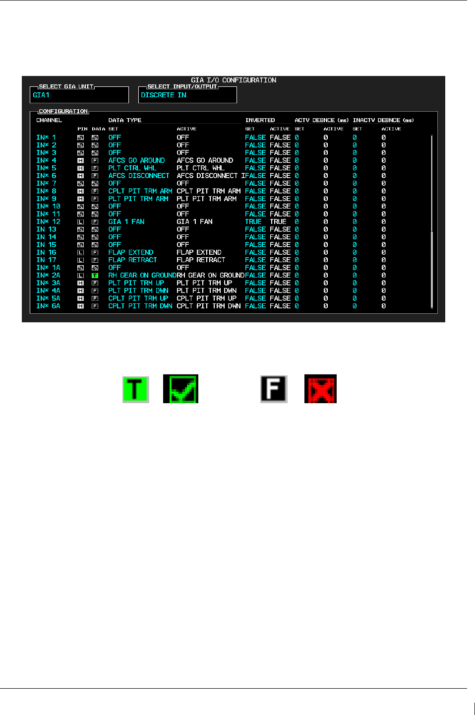
G1000/GFC700 System Maintenance Manual – C90A/C90GT/C90GTi King Air Page 4-19
190-00682-01 Revision G
4.8 Flaps-in-Motion Discrete Input Check
To perform this check, all G1000 and GFC 700 equipment must be installed and operational. Start the
G1000 system in Configuration Mode and go to the GIA Page Group and select the GIA I/O
Configuration Page using the FMS knob. Perform the following checks:
Figure 4-2. GIA I/O Page
TRUE/VALID
FALSE/INVALID
or
or
Figure 4-3. Discrete Indications
NOTE
Reference Table 3-1 for interpretation of data indicator symbols
1. Verify the DATA indicators of the discrete inputs labeled ‘FLAP EXTEND’ and ‘FLAP
RETRACT’ show a FALSE/INVALID condition.
2. Extend the flaps down. While the flaps are traveling down, check that the DATA indicator of the
discrete input labeled ‘FLAP EXTEND’ changes to a TRUE/VALID condition.
3. When the flap motion is completed, verify the DATA indicators of the discrete inputs labeled
‘FLAP EXTEND’ and ‘FLAP RETRACT’ show a FALSE/INVALID condition.
4. Retract the flaps up. While the flaps are traveling up, check that the DATA indicator of the
discrete input labeled ‘FLAP RETRACT’ changes to a TRUE/VALID condition.
5. When the flap motion is completed, verify the DATA indicators of the discrete inputs labeled
‘FLAP EXTEND’ and ‘FLAP RETRACT’ show a FALSE/INVALID condition.
6.
Repeat steps 1 through 5 for GIA2.
7.
The flap discrete input check is complete.
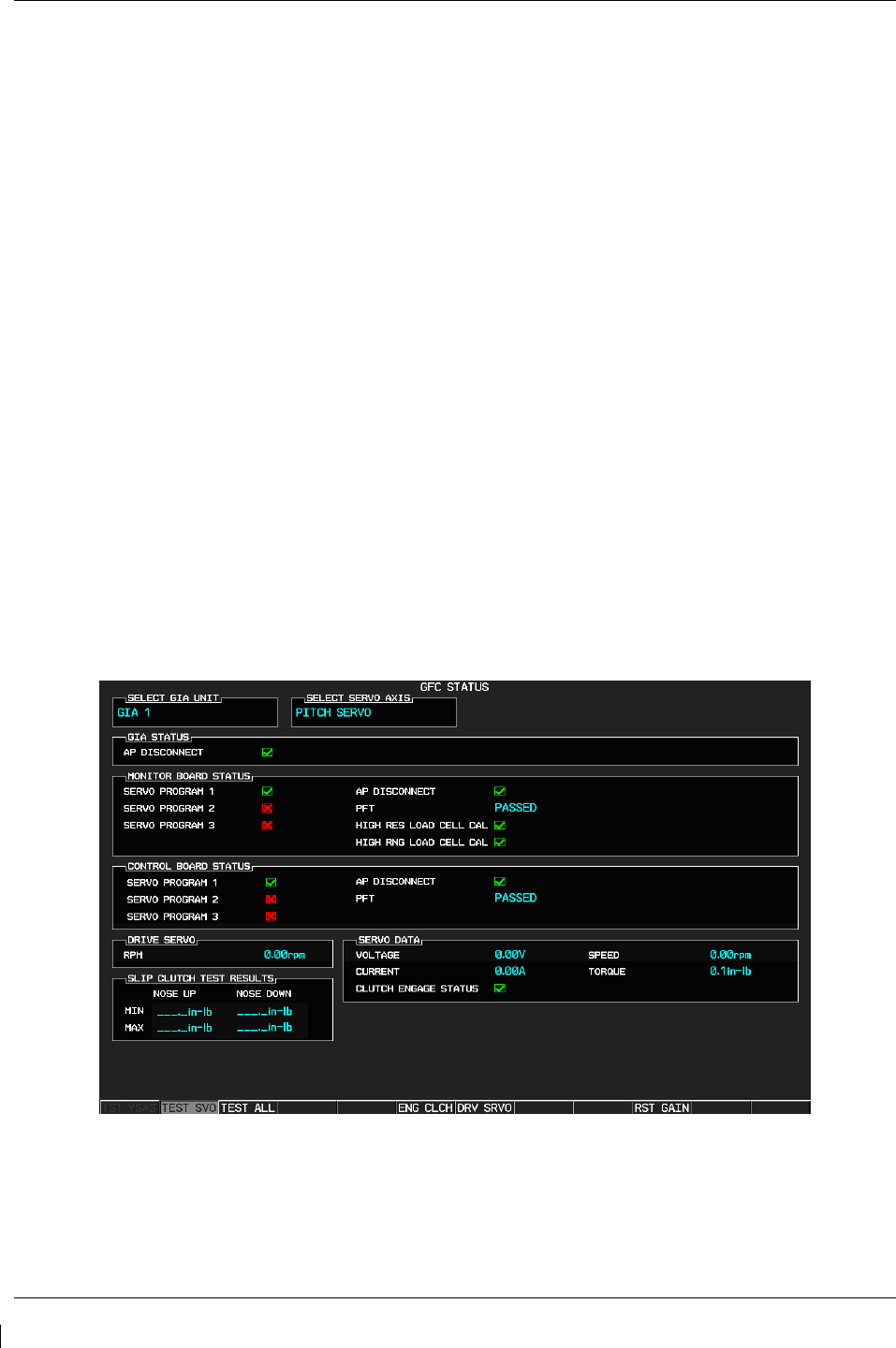
Page 4-20 G1000/GFC700 System Maintenance Manual – C90A/C90GT/C90GTi King Air
Revision G 190-00682-01
4.9 Slip Clutch Torque Check Procedure and Servo Current Display Check
Sections 4.9.1 thru 4.9.4 are applicable as follows:
• Section 4.9.1: Automatic test for GSM 85A or GSM 86 with SW version 0636.03 and subs
o Includes servo current check
• Section 4.9.2: Manual test for GSM 85A with SW version 0636.02 and earlier
o Includes servo current check
• Section 4.9.3: Fixture procedure for GSM 85A or GSM 86
• Section 4.9.4: Servo current check
o The servo current check can be accomplished as part of Section 4.9.1 or Section 4.9.2. If
neither of those sections is being performed, this section is required.
4.9.1 Automatic Slip Clutch Test Procedure (SW Version 0636.03 and Subs)
To ensure proper operation during this test, it is necessary to remove power from the aircraft prior to
starting.
1. Press and hold the enter button on PFD1, and restore power to the aircraft.
2. With PFD1 in Configuration Mode, verify the correct type of servo gearbox is configured for each
servo per Section 3.9.4.13. Step 9.
2. Go to the GFC Page Group and select the GFC STATUS page using the FMS knobs.
3. With the MFD in Normal Mode, press the red DISPLAY BACKUP button on the pilot’s GMA audio
panel to place the MFD in reversion mode.
Figure 4-4 GFC Status Page
NOTE
The displayed test results on the PFD are not stored in G1000 memory. If power
is cycled, these values will be lost. However, these test values are not lost by
changing configuration mode pages.

G1000/GFC700 System Maintenance Manual – C90A/C90GT/C90GTi King Air Page 4-21
190-00682-01 Revision G
IMPORTANT!
It is highly recommended that the following test be performed at temperatures
between 50° F and 120° F.
4. Use the FMS knob to select the desired servo (PITCH, ROLL, YAW or PITCH TRIM).
5. Verify that the PFT status field shows PASSED.
6. Verify that the aircraft control surface to be checked is free to travel throughout its range of motion.
7. Press the TEST SVO softkey on the PFD. Follow prompts to begin the test.
IMPORTANT!
If the test must be stopped, firmly grasp the aircraft control being moved and press
the red AP DISC switch on the aircraft control wheel. If an abnormal disconnect of
a servo occurs, reset the AFCS SERVO circuit breaker and repeat the test.
8. During operation of the servo, observe the CURRENT field and verify that the current displayed
varies during operation
9. When test is completed, verify the CLUTCH TEST PASS message is displayed on the MFD.
10. Repeat steps 4 through 8 for each servo axis (Pitch, Roll, Yaw and Pitch Trim).
11. If the CLUTCH TEST FAIL message is displayed on the MFD for any axis, repeat the test twice in
the failed axis. If the test does not pass, the servo gearbox must be removed from the aircraft and
tested/adjusted per the
12. Servo Adjustment Fixture
Procedure
in Section 4.9.3.
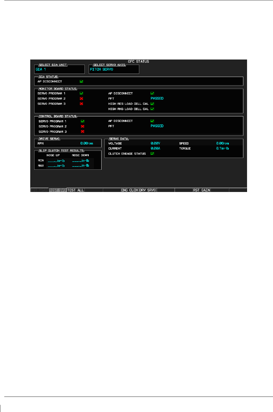
Page 4-22 G1000/GFC700 System Maintenance Manual – C90A/C90GT/C90GTi King Air
Revision G 190-00682-01
4.9.2 Manual Slip Clutch Test Procedure (SW Version 0636.02 and earlier)
1. With PFD1 in Configuration Mode, go to the GFC Page Group and select the GFC STATUS page
using the FMS knobs.
Figure 4-5 GFC Status Page
NOTE
The displayed test results on the PFD are not stored in G1000 memory. If power
is cycled, these values will be lost. However, these test values are not lost by
changing configuration mode pages.
IMPORTANT!
It is highly recommended that the following test be performed at temperatures
between 50° F and 120° F.
2. Use the FMS knob to select the desired servo (PITCH, ROLL, YAW or PITCH TRIM).
3. Verify that the PFT status field shows PASSED.
4. Verify that the aircraft control surface to be checked is free to travel throughout its range of motion.
5. Press the ENG CLCH softkey on the PFD.
6. With the clutch engaged, take hold of the aircraft controls and manually overcome the clutch. Move
the control surface to be tested from stop to stop a minimum of two times each direction.
7. Position the control surface in the neutral position (full aft position if the PITCH SERVO is
selected). Press the DIS CLCH softkey.

G1000/GFC700 System Maintenance Manual – C90A/C90GT/C90GTi King Air Page 4-23
190-00682-01 Revision G
IMPORTANT!
If the test must be stopped, firmly grasp the aircraft control being moved and press
the red AP DISC switch on the aircraft control stick. If an abnormal disconnect of a
servo occurs, reset AFCS SERVO circuit breaker and repeat the step.
8. Manually select +2.50 rpm for the Drive Servo and press ENT.
9. Press the ENG CLCH softkey.
10. Press the DRV SRVO softkey.
11. Allow the selected servo to drive the control surface to either the NOSE DOWN stop (Pitch and Pitch
Trim) or the LEFT stop (Roll and Yaw).
12. During operation of the servo, observe the CURRENT field and verify that the current displayed
varies during operation
13. Allow the servo to continue driving against the control stop for at least 50 seconds. Observe the
TORQUE values displayed in the Servo Data field and record the maximum and minimum values in
Table 4-10 or in the appropriate aircraft maintenance records.
14. Manually select 0.00 rpm for the Drive Servo and press ENT. Allow the servo to stop.
15. Manually select -2.50 for the Drive Servo and press ENT. Allow the selected servo to drive the
control surface to either the NOSE UP stop (Pitch and Pitch Trim) or the RIGHT stop (Roll and
Yaw). If the PITCH SERVO is selected, firmly hold the control yoke in the full aft position until the
NOSE UP portion of the test is completed.
16. Allow the servo to continue driving against the control stop for at least 50 seconds. Observe the
TORQUE values displayed in the Servo Data field and record the maximum and minimum values in
Table 4-10 or in the appropriate aircraft maintenance records.
17. Manually select 0.00 rpm for the Drive Servo and press ENT. Allow the servo to stop.
18. Firmly grasp the aircraft control under test and press the DIS CLCH softkey.
19. Press the STP SRVO softkey.
20. Repeat steps 2 through 18 for each servo axis shown.
21. Verify that the minimum and maximum torque values measured are within the Minimum and
Maximum torque values allowed, for the given axis, listed in Table 4-10.

Page 4-24 G1000/GFC700 System Maintenance Manual – C90A/C90GT/C90GTi King Air
Revision G 190-00682-01
Axis Direction
Min Measured
Torque (in-lbs)
Max Measured
Torque (in-lbs)
Min Allowed
Torque (in-lbs)
Max Allowed
Torque (in-lbs)
Pitch Up 76 105
Down
Roll Left 63 87
Right
Yaw Left 56 99
Right
Pitch
Trim
Up
39 53
Down
Table 4-10. Measured Torque
NOTE
If the measured values exceed the limits in Table 4-10, the servo must be removed from the aircraft and
tested/adjusted per the
Servo Adjustment Fixture Procedure in Section 4.9.3.
4.9.2.1 Abnormal Test Prompts
During the testing, the following prompts may be displayed indicating an abnormality encountered during
the test. Use the following guidelines to troubleshoot.
Message Prompt
Probable Cause
Action
STOP NOT REACHED
The servo did not detect a torque
value which exceeded 70% of the
established mechanical torque limit
within 1 minute of starting the test. A
low slip clutch setting is the likely
cause.
Repeat test.
If the same result is received,
remove servo mount and check/set
clutch on stand.
SERVO TORQUE TOO HIGH
The servo detected an average
torque value which exceeded 130%
of the established mechanical torque
limit. Likely causes include a high
slip clutch setting, or excess friction
encountered during the control
surface travel.
Engage the autopilot for the axis
which reported torque to high.
Manually operate the controls and
verify that the clutch can be
overridden. If the clutch can slip,
repeat the test again. Otherwise
remove the servo mount and reset
the clutch.
Check control friction against aircraft
maintenance specifications.
If the same result is received on
retest, remove servo mount and
check/set clutch on stand.
SERVO TORQUE TOO LOW
The servo detected an average
torque value which fell below 70% of
the established mechanical torque
limit after detecting that the stop was
reached.
Likely causes include a low slip
clutch setting or a disturbance in the
Repeat test again. If the same result
is received, remove servo mount and
check/set clutch on stand.

G1000/GFC700 System Maintenance Manual – C90A/C90GT/C90GTi King Air Page 4-25
190-00682-01 Revision G
controls before reaching the stop.
INVALID SERVO SPEED
The servo is unable to maintain the
required ~2.5 RPM during the test
(Speed drops below 2 RPM or
exceeds 3 RPM)
Repeat test again.
If the same result is received,
remove servo mount and check/set
clutch on stand.
If resetting clutch does not clear
message, replace servo motor.
TEST SPEED FAIL Servo has not responded to the test
initialization command.
Repeat test again.
If message does not clear,
troubleshoot the servo and it’s wiring
for the source of the failure.
Repeat test when the source of the
servo failure has been corrected.
SERVO TEST TIMED OUT Servo not responding for over 60
seconds during testing.
SERVO DATA TIMED OUT The servo has failed to transmit load
cell sensor status.
LOAD CELL INVALID
A special test monitor has detected
an inequality between motor torque
and load cell torque greater than the
specified threshold. An out-of-
calibration load cell may be the
cause.
Replace servo motor and repeat test.
AIRBORNE STATUS
The G1000 system has detected
airborne status, (determined by true
airspeed) and has cancelled the test.
Verify the ADC is online.
Check pitot/static system is free of
obstructions and plumbing kinks.
Repeat test.
4.9.3 Servo Adjustment Fixture Procedure
Remove the GSM 85A (or GSM 86 if installed) Servo Mount as per Section 6.12.
The slip clutch torque values must be checked, and adjusted if necessary, to the values listed in Table
4-11.
IMPORTANT!
This adjustment requires the use of the Garmin servo adjustment fixture, P/N T10-
00110-01. For detailed operating instructions for the fixture, refer to GSA8X /
GSM85(A) Installation Manual, listed in Table 1-3.
1. Perform this procedure within a temperature range of 50 °F to 120 °F.
2. If a protective cover is installed on the servo mount, remove the protective cover.
3. Place the servo mount on the slip-clutch adjustment fixture and secure with the toggle clamps.
Install the fixture cable between the capstan under test and the fixture capstan. Remove the slack
in the cable using the tension adjustment knob. Tighten the two wing nuts on bottom of fixture
while holding the top thumbscrews.

Page 4-26 G1000/GFC700 System Maintenance Manual – C90A/C90GT/C90GTi King Air
Revision G 190-00682-01
4. Attach a socket to a calibrated torque wrench of appropriate range and place on top of the fixture
capstan. Adjust the wrench support fixture so that it contacts the handle in the appropriate
location.
5. Connect a 2 Amp, 24 V, DC power supply to the fixture.
6. Place the solenoid switch to "on" and move the direction switch to the clockwise or counter-
clockwise position. Allow the clutch to rotate at least one revolution in each direction (note: the
capstan itself is fixed.)
7. Observe the torque reading for at least two full revolutions in each direction. Ensure the
minimum and maximum torque readings are within the tolerance specified.
8. If the minimum and maximum torque values are within the specified range in Table 4-11, the
GSM slip clutch is acceptable. Reinstall the GSM 85A or GSM 86 servo gearbox per Section
6.12.
9. If the minimum and maximum torque values are not within the specified range in Table 4-11, the
GSM 86 slip clutch cartridge must be replaced or the GSM 85A must be adjusted.
10. For GSM 85A only: If adjustment is required, remove cotter pin and adjust the nut on the capstan
as needed to obtain the torque value listed in Table 4-11, as shown on the torque wrench.
Position the nut to align with holes in the capstan shaft and install a new cotter pin.
11. When finished, remove the fixture cable, and then remove the servo gearbox from the fixture.
12. Install the GSM 85A or GSM 86 servo gearbox per Section 6.12.
Table 4-11. Slip Clutch Torque Settings
Servo Pitch Trim* Pitch Yaw Roll
GSM 85A Setting 49 +/-6 in-lbs* 88 +/-10 in-lbs 83 +/-10 in-lbs 73 +/-9 in-lbs
GSM 86 Setting 45 +/-13 in-lbs* 90+/-24 in-lbs 90 +/-18 in-lbs 72+/-21 in-lbs
*Valid with continuous travel servo gearbox only
4.9.4 Servo Current Display Check
To ensure proper operation during this test, it is necessary to remove power from the aircraft prior to
starting.
1. Press and hold the enter button on PFD1, and restore power to the aircraft.
2. With PFD1 in Configuration Mode, go to the GFC Page Group and select the GFC STATUS page
using the FMS knobs.
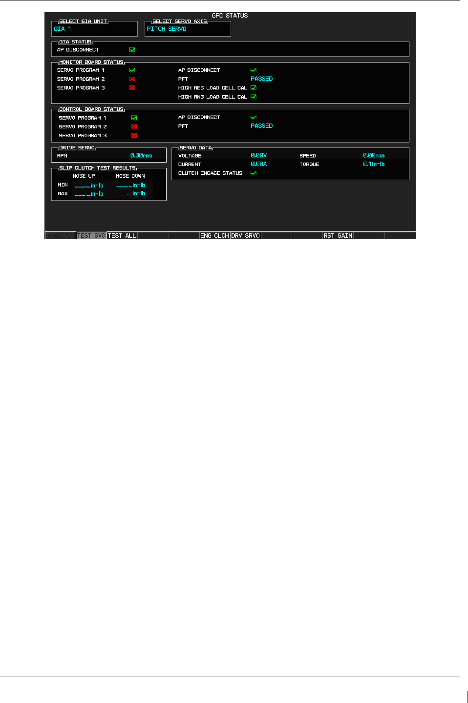
G1000/GFC700 System Maintenance Manual – C90A/C90GT/C90GTi King Air Page 4-27
190-00682-01 Revision G
Figure 4-6 GFC Status Page
IMPORTANT!
It is highly recommended that the following test be performed at temperatures
between 50° F and 120° F.
3. Use the FMS knob to select the desired servo (PITCH, ROLL, or YAW).
4. Verify that the aircraft control surface to be checked is free to travel throughout its range of motion.
5. Manually select +2.50 rpm for the Drive Servo and press ENT.
6. Press the ENG CLCH softkey.
7. Press the DRV SRVO softkey. During operation of the servo, observe the CURRENT field and
verify that the current displayed varies during operation.
IMPORTANT!
Once the test starts the servo will begin to move the aircraft controls. If the test must be
stopped, firmly grasp the aircraft control being moved and press the red AP DISC switch
on the aircraft control stick.
8. Allow the selected servo to drive the control surface to either the NOSE DOWN stop (Pitch) or the
LEFT stop (Roll and Yaw). If the Pitch servo is selected, firmly hold the control yoke in the full
forward position until the NOSE DN test is completed.
9. Manually select 0.00 rpm for the Drive Servo and press ENT. Allow the servo to stop.
10. Firmly grasp the aircraft control under test and press the DIS CLCH softkey.
11. Press the STP SRVO softkey.
12. Repeat steps 2 through 10 for each servo axis shown.

Page 4-28 G1000/GFC700 System Maintenance Manual – C90A/C90GT/C90GTi King Air
Revision G 190-00682-01
4.10 G1000 Redundant Connection Check
Perform the following steps to verify the following connections are intact:
(A) The primary (PRI) and secondary (SEC) power sources for GIA 1, GRS 1, PFD 1, and GDC 1
(B) The AHRS and ADC data path
(C) PFD and MFD Ethernet connection (includes ARINC connection between ADC and MFD and
DISPLAY BACKUP button function)
(D) Engine data availability to the displays and GPS data availability to the AHRS with either GIA
inoperative:
NOTE
Reference Table 3-1 for interpretation of data indicator symbols
(A) PRI and SEC power sources for PFD 1, GIA 1, GRS 1 and GDC 1 check
1. Connect a ground power unit to the external power receptacle and turn on the ground power unit.
2. Set the BAT, EXT PWR and AVIONICS MASTER PWR switches to ON.
3. With the G1000 system in normal mode, pull the following circuit breakers on the right hand circuit
breaker panel:
• PFD 1 (PRI)
• AHRS 1 (PRI)
• ADC 1 (PRI)
• GIA 1 (PRI)
4. Wait at least 5 seconds, then verify the data on PFD1 remains valid and the following alert messages
are not present:
• GIA 1 FAIL (or any related message such as COM1, NAV1, XPDR1, GPS1)
• AHRS 1 FAIL
• ADC 1 FAIL
• FAILED DATA PATH
5. Close the circuit breakers listed in step 3.
6. Repeat step 4.
7. Pull the following circuit breakers on the right hand circuit breaker panel:
• PFD 1 (SEC)
• AHRS 1 (SEC)
• ADC 1 (SEC)
• GIA 1 (SEC)
8. Wait at least 5 seconds, then repeat step 4.
9. Close the circuit breakers listed in step 7.

G1000/GFC700 System Maintenance Manual – C90A/C90GT/C90GTi King Air Page 4-29
190-00682-01 Revision G
(B) AHRS and ADC data path check
1. Verify there are no AHRS loss-of-data messages, such as:
• AHRS not receiving any GPS information
• AHRS not receiving backup GPS information
• AHRS using backup GPS source
2. Place the G1000 in configuration mode.
3. In the GIA page group, go to the GIA RS-232/ARINC 429 CONFIG page.
4. With GIA1 selected in the SELECT UNIT window, verify the RS232 Channel 1
(GDC74 #1) and RS232 Channel 6 (GRS77 #1) show valid indicators. Ref. Section 5.2.1.2.
5. With GIA1 selected in the SELECT UNIT window, verify the ARINC 429 IN5
(GDC74 #1) and ARINC 429 IN6 (GRS77 #1) show valid indicators. Ref. Section 5.2.1.2.
6. With GIA2 selected in the SELECT UNIT window, verify the RS232 Channel 1
(GDC74 #2) and RS232 Channel 6 (GRS77 #2) show valid indicators. Ref. Section 5.2.1.2.
7. With GIA2 selected in the SELECT UNIT window, verify the ARINC 429 IN5
(GDC74 #2) and ARINC 429 IN6 (GRS77 #2) show valid indicators. Ref. Section 5.2.1.2.
8. In the PFD page group, go to the GIA RS-232/ARINC 429 CONFIG page.
9. With PFD1 selected in the SELECT UNIT window, verify the ARINC 429 IN1
(GRS77 #1) and ARINC 429 IN2 (GDC74 #1) show valid indicators. Ref. Section 5.2.1.1.
10. With PFD2 selected in the SELECT UNIT window, verify the ARINC 429 IN1
(GRS77 #2) and ARINC 429 IN2 (GDC74 #2) show valid indicators. Ref. Section 5.2.1.1.
(C) PFD and MFD Ethernet connection check (includes ARINC connection check between ADC1
and MFD and between GRS1 and MFD, and the DISPLAY BACKUP button check)
1. Re-start PFD 2, PFD 1 and MFD in normal mode.
2. On the right hand circuit breaker panel, open the
MFD circuit breaker
:
3. Verify NAV 1, COM 1, NAV 2 and COM 2 remain valid on both PFD 1 and PFD 2.
4. Close the MFD circuit breaker and wait for MFD to initialize:
5. Open the PFD 2 circuit breaker:
6. Press the DISPLAY BACK UP button on the Pilot’s GMA 1347D audio panel.
7. Verify NAV 2 and COM 2 are each replaced by a red X and NAV 1 and COM 1 remain
valid on both the MFD and PFD 1.
8. Press the DISPLAY BACK UP button on the Pilot’s GMA 1347D audio panel to return to
normal mode.
9. Close the PFD 2 circuit breaker and wait for PFD 2 to initialize:
10. Open the PFD 1 (PRI) and PFD 1 (SEC) circuit breakers:
11. Press the DISPLAY BACK UP button on the Co-pilot’s GMA 1347D audio panel.
12. Verify NAV 1 and COM 1 are each replaced by a red X and NAV 2 and COM 2 remain
valid on both the MFD and PFD 2.
13. Press the DISPLAY BACK UP button on the Co-pilot’s GMA 1347D audio panel to return
to normal mode.
14. Close the PFD 1 (PRI) and PFD 1 (SEC) circuit breakers and wait for PFD 1 to initialize:

Page 4-30 G1000/GFC700 System Maintenance Manual – C90A/C90GT/C90GTi King Air
Revision G 190-00682-01
(D) Engine data availability to the displays and GPS data availability to the AHRS with either GIA
inoperative check
1. Open GIA1 primary and secondary CBs.
2. Verify the following:
a. NAV 1 and COMM1 tuning fields on PFD 1 and PFD 2 are invalid (red X).
b. L/R engine data remains valid.
c. XPDR1 is Inoperative.
d. GMA1 Is Inoperative.
e. AHRS1 is using backup GPS source.
f. AHRS2 not receiving backup GPS Information.
g. An amber BOTH ON GPS2 is displayed on PFD 1 and PFD 2.
h. AHRS and ADC data remain valid on PFD 1 and PFD 2.
3. Close GIA1 primary and secondary CBs. Allow system to re-acquire satellites and return to
normal display modes.
4. Open GIA2 CB.
5. Verify the following:
a. NAV2 and COMM2 tuning fields on PFD 1 and PFD 2 are invalid (red X).
b. L/R engine data remains valid.
c. XPDR2 is Inoperative.
d. GMA2 Is Inoperative.
e. AHRS2 is using backup GPS source.
f. AHRS1 not receiving backup GPS Information.
g. An amber BOTH ON GPS1 is displayed on PFD 1 and PFD 2.
h. AHRS and ADC data remain valid on PFD 1 and PFD 2.
6. Close GIA2 CB. Allow system to re-acquire satellites and return to normal display modes.
7. Open GIA1 primary and secondary CBs and GIA2 CB.
8. Verify the following:
a. COM1/NAV1 & COM2/NAV2 fields flag invalid.
b. GPS CDI flags DR on PFD.
c. NAV1 & NAV2 CDI loses deviation bar.
d. XPDR field flags invalid on PFD.
e. Engine Instrument field flags invalid on MFD.
f. All AHRS & ADC fields remain valid.
g. Red AFCS status annunciation given.
h. If equipped with TAWS, TAWS FAIL annunciation given.
i. If equipped with ADF and/or DME, ADF/DME windows flag invalid.
9. Restore power to both GIA units.
G1000/GFC700 System Maintenance Manual – C90A/C90GT/C90GTi King Air Page 4-31
190-00682-01 Revision G
4.11 Engine Data Check
Do the following to verify the engine data availability and validity for torque, ITT, and oil pressure.
Required test equipment is provided in the table below.
Test Equipment Make/Requirement Model/Part Nbr
Decade Box 0-1k ohms As appropriate
Signal Generator 0-10Vdc / 0 – 1k Hz As appropriate
Torque
1. Using a signal generator, inject a DC signal into the No. 1 GEA via left engine firewall
connectors-pins J102-C (HI) and J102-R (LO).
2. Simulate the following voltages, and verify the indication and status:
Test Point (Vdc) Indication (ft-lbs) Status Configurations
0.00 +/- .02
0
bottom of green band
Green digital all
2.53 +/- .02 1320
red digital*
NOTE: red radial 1315 4-10, 21-22
2.90 +/- .02 1525
red digital*
NOTE: red radial 1520 1-3, 14-20
3.15 +/- .02
1655
red digital*
NOTE: red radial 1650 11-13
(*) steady after 5 seconds
3. On the right hand circuit breaker panel, open the GIA1 (PRI) and GIA1 (SEC) circuit
breakers, and verify the last observed torque indication remains unchanged.
4. Close the GIA1 (PRI) and GIA1 (SEC) circuit breakers, and wait until the COM1 and
NAV1 fields are valid.
5. Repeat steps 1 and 2 using the No. 2 GEA via right engine firewall connectors-pins J103-C
(HI) and J103-R (LO).
6. Pull the GIA 2 circuit breaker, and verify the last observed torque indication remains
unchanged.
7. Close the GIA 2 circuit breaker, and wait until the COM2 and NAV2 field are valid.
ITT
8. Remove left engine ITT thermocouple terminals from sensor. Using a signal generator,
inject a DC signal into the No. 1 GEA via left engine firewall connectors-pins, as follows:
S/N LJ-1063 thru LJ-1360, LJ-1362: J104-T* (LO) and J104-W* (HI)
S/N LJ-1361, LJ-1363 and after: J104-P* (LO) and J104-S* (HI)
9. Simulate the following voltages, and verify the indication and status:
Page 4-32 G1000/GFC700 System Maintenance Manual – C90A/C90GT/C90GTi King Air
Revision G 190-00682-01
Test Point (mV) Indication (degC) Status Configurations
16.40 +/- .28
400*
bottom of green band
green digital all
44.3 +/- .28 1090*
red triangle, start mode
red digital** all
(*) verify value displayed is within test point tolerances
(**) steady after 5 seconds
10. On the right hand circuit breaker panel, open the GIA1 (PRI) and GIA1 (SEC) circuit
breakers, and verify the last observed ITT indication remains unchanged.
11. Close the GIA1 (PRI) and GIA1 (SEC) circuit breakers, and wait until the COM1 and
NAV1 fields are valid.
12. Repeat steps 8 and 9 using the No. 2 GEA via right engine firewall connectors-pins
specified below and right engine ITT thermocouple.
S/N LJ-1063 thru LJ-1360, LJ-1362: J105-T* (LO) and J105-W* (HI)
S/N LJ-1361, LJ-1363 and after: J105-P* (LO) and J105-S* (HI)
13. Pull the GIA 2 circuit breaker, and verify the last observed ITT indication remains
unchanged.
14. Close the GIA 2 circuit breaker, and wait until the COM2 and NAV2 field are valid.
Oil Pressure
15. Using a signal generator, inject a DC signal into the No. 1 GEA via left engine firewall
connectors-pins J104-A (LO) and J104-B (HI).
16. Simulate the following voltages, and verify the indication and status:
Test Point (Vdc) Indication (PSI) Status Configurations
.98 +/- .1
39 +/- 1
red digital
NOTE: low red radial 40 all
2.0 +/- .1 80 +/- 1
bottom of green band
Green digital 4-10, 21-22
2.1 +/- .1 85 +/- 1
bottom of green band
Green digital 1-3, 11-20
17. On the right hand circuit breaker panel, open the GIA1 (PRI) and GIA1 (SEC) circuit
breakers, and verify the last observed oil pressure indication remains unchanged.
18. Close the GIA1 (PRI) and GIA1 (SEC) circuit breakers, and wait until the COM1 and
NAV1 fields are valid.
19. Repeat steps 15 and 16 using the No. 2 GEA via right engine firewall connectors-pins J105-
A (LO) and J105-B (HI).
20. Pull the GIA 2 circuit breaker, and verify the last observed oil pressure indication remains
unchanged.
21. Close the GIA 2 circuit breaker, and wait until the COM2 and NAV2 field are valid.
22. Disconnect test equipment.
23. Reconnect the following firewall connectors, and verify all engine parameters are displayed
valid on the MFD with no Red X’s: J102, J103, J104, J105

G1000/GFC700 System Maintenance Manual – C90A/C90GT/C90GTi King Air Page 4-33
190-00682-01 Revision G
4.12 Trim Annunciator Check
This procedure will check the trim annunciation from both GIA 1 and GIA 2.
1. Ensure the G1000 is in normal mode, the autopilot is not engaged, and the GMC 710 XFR
key is selected to the pilot’s side.
2. Press the left part of the pilot’s pitch-trim switch upwards for approximately 10 seconds and
verify that the red PTRM annunciation is displayed on both PFD 1 and PFD 2. Release the
switch and wait for the PTRM annunciation to clear.
3. Press the left part of the pilot’s pitch-trim switch downwards for approximately 10 seconds
and verify that the red PTRM annunciation is displayed on both PFD 1 and PFD 2. Release
the switch and wait for the PTRM annunciation to clear.
4. Repeat Steps 2 and 3 for the right part of the pilot’s pitch-trim switch.
5. Repeat Steps 2 through 4 for the copilot’s pitch-trim switch.
6. Select copilot side by pressing the XFR key on the GMC 710 (changes active GIA to GIA
2).
7. Repeat Steps 2 through 5 and verify annunciations are displayed on both PFD 1 and PFD 2.
8. Re-select pilot side by pressing XFR key on the GMC 710 (changes active GIA back to
GIA 1).
9. Move the control yoke to the center position and hold and center the pitch trim wheel.
10. Press the Go Around switch on the throttle, then engage the autopilot and apply a forward
load on the control yoke. Verify that the pitch trim wheel rotates in the nose up direction.
11. Disconnect the autopilot by pressing the AP DISC button.
12. Use the pitch-trim switch (or the pitch-trim wheel) to trim full nose down.
13. Move the control yoke to the full forward position and hold.
14. Engage the autopilot, maintain the control yoke in the forward position and keep the pitch-
trim wheel from rotating for approximately five seconds. Quickly release the trim wheel
and verify that the red PTRM annunciator is displayed on both PFD 1 and PFD 2.
15. Disengage the autopilot and use the pitch-trim switch (or the pitch-trim wheel) to trim full
up.
16. Move the control yoke to the full forward position and hold.
17. Engage the autopilot, apply firm aft pressure on the control yoke for approximately 15
seconds, allowing the pitch-trim wheel to move freely. Verify that the amber ELE ↓
annunciator is displayed on both PFD 1 and PFD 2.
18. Disengage the autopilot and use the pitch-trim switch (or the pitch-trim wheel) to trim full
down.
19. Move the control yoke to the full aft position and hold.
20. Engage the autopilot, apply firm forward pressure on the control yoke for approximately 15
seconds, allowing the pitch-trim wheel to move freely. Verify that the amber ELE ↑
annunciator is displayed on both PFD 1 and PFD 2.
21. Disengage the autopilot and rotate the control yoke to the full left position and hold.

Page 4-34 G1000/GFC700 System Maintenance Manual – C90A/C90GT/C90GTi King Air
Revision G 190-00682-01
22. Engage the autopilot, apply firm right load on the control yoke for approximately 10
seconds. Verify that the amber AIL → annunciator is displayed on both PFD 1 and PFD 2.
23. Disengage the autopilot and rotate the control yoke to the full right position and hold.
24. Engage the autopilot, apply firm left load on the control yoke for approximately 10 seconds.
Verify that the amber ← AIL annunciator is displayed on both PFD 1 and PFD 2.
25. Disengage the autopilot.
26. Engage the autopilot, apply firm load on the right rudder pedal for approximately 15
seconds. Verify that the amber ← RUD annunciator is displayed on both PFD 1 and PFD
2.
27. Disengage the autopilot.
28. Engage the autopilot, apply firm load on the left rudder pedal for approximately 15 seconds.
Verify that the amber RUD → annunciator is displayed on both PFD 1 and PFD 2.
29. The Trim Annunciator Check is complete.
4.13 G1000 Miscompare Checks
This procedure will check the AHRS, airspeed and altitude miscompare monitors. Accomplish the
following checks with the aircraft positioned where it can receive GPS signals and magnetic heading.
Access to AHRS1 and AHRS2 will be required during this test.
1. Ensure the G1000 is operating in normal mode.
2. Connect a pitot/static test set to the aircraft ADC1 pitot and static ports (Pilot’s side). (Do
not connect the pitot/static tester to ADC2 ports at this time)
3. Set the baro-correction on PFD1 and PFD2 to 29.92in/hg.
4. On the AFCS mode controller, press the AP button and verify autopilot engages.
5. Slowly increase the pitot/static test set to simulate an ADC1 / ADC2 altitude miscompare of
greater than 200 ft., verify ADC2 altitude does not increase, autopilot does not disconnect
and amber comparator window text “ALT MISCOMP” is displayed on PFD1 and PFD2.
6. Reduce ADC1 altitude to ambient pressure.
7. Repeat Step 5 with the pitot/static test set connected to the aircraft ADC2 pitot and static
ports.
8. Use the pitot/static test set to simulate an airspeed of 40 kts for ADC1 and 55 kts for ADC2.
Verify the autopilot does not disconnect and amber comparator window text
“IAS MISCOMP” is displayed on PFD 1 and PFD2.
9. Use the pitot/static test set to simulate an airspeed of 55 kts for ADC1 and 40 kts for ADC2.
Verify the autopilot does not disconnect and amber comparator window text
“IAS MISCOMP” is displayed on PFD 1 and PFD2.
10. Use the pitot/static test set to simulate an airspeed of 85 kts for ADC1 and 95 kts for ADC2.
Verify the autopilot does not disconnect and amber comparator window text
“IAS MISCOMP” is displayed on PFD 1 and PFD2.
11. Use the pitot/static test set to simulate an airspeed of 95 kts for ADC1 and 85 kts for ADC2.
Verify the autopilot does not disconnect and amber comparator window text
“IAS MISCOMP” is displayed on PFD 1 and PFD2.
12. Reduce ADC1 and ADC2 airspeeds to 0 kts.
13. Slowly rotate AHRS1 along the lateral (pitch) axis to a pitch attitude of greater than 5
degrees, verify the following:

G1000/GFC700 System Maintenance Manual – C90A/C90GT/C90GTi King Air Page 4-35
190-00682-01 Revision G
a. AHRS2 pitch attitude does not change
b. An amber “PIT MISCOMP” is annunciated on PFD1 and PFD2
c. Autopilot disconnects at approximately 5 deg AHRS1 / AHRS2 miscompare
d. The autopilot disconnect audio alert (two hi-low tones) sounds
e. A red flashing AP annunciator on PFD1 and PFD2
f. Flight director command bars remain in view with PIT and ROL modes annunciated
14. Replace AHRS1 to normal attitude and verify that attitude display on PFD1 displays current
aircraft attitude.
15. Use the AFCS mode controller to re-engage autopilot.
16. Slowly rotate AHRS1 along the longitudinal (roll) axis to a roll attitude of greater than 5
degrees, verify the following:
a. AHRS2 roll attitude does not change
b. An amber “ROL MISCOMP” is annunciated on PFD1 and PFD2
c. Autopilot disconnects at approximately 5 deg AHRS1 / AHRS2 miscompare
d. The autopilot disconnect audio alert (two hi-low tones) sounds
e. A red flashing AP annunciator on PFD1 and PFD2
f. Flight director command bars remain in view with autopilot in PIT and ROL mode
17. Replace AHRS1 to normal attitude and verify that attitude display on PFD1 displays current
aircraft attitude.
18. Repeat Steps 13 through 17 for AHRS2.
19. The G1000 Miscompare checks are complete.

Page 4-36 G1000/GFC700 System Maintenance Manual – C90A/C90GT/C90GTi King Air
Revision G 190-00682-01
4.14 Nose Avionics Compartment Fans Operational Check
This procedure will verify that airflow is present from the ported avionics cooling fans to the #1 and #2
GIA and GTX units. The fan speed monitoring circuits and annunciations are checked by the G1000
Cooling System Electrical Check in Section 8.1.4 and a Visual Inspection of the fan hoses is
accomplished in Section 4.4. This check requires the G1000 to be powered on.
1. Gain access to the nose avionics compartment.
2. Disconnect cooling fan hose from the pilot side GTX and verify airflow is present.
3. Reconnect the cooling fan hose to the GTX and secure per Nose Bay Electrical Equipment
Install drawing 005-00375-34, Rev 5 or subsequent.
4. Disconnect cooling fan hose from the pilot side GIA GTX and verify airflow is present.
5. Reconnect the cooling fan hose to the GIA and secure per Nose Bay Electrical Equipment
Install drawing 005-00375-34, Rev 5 or subsequent.
6. Repeat Steps 2 through 5 for the copilot side GTX and GIA.
7. The Nose Avionics Compartment Fans Operational Check is complete.
4.15 Instrument Panel Fans Operational Check
This procedure will verify that airflow is present from the PFD1, MFD and PFD2 cooling fans. The fan
speed monitoring circuits and annunciations are checked by the G1000 Cooling System Electrical Check
in Section 8.1.4. This check requires the G1000 to be powered on.
1. Remove PFD1 as described in Section 6.1 Steps 1 and 2 (Removal).
2. Identify the PFD1 cooling fan and verify airflow is present.
3. Reinstall PFD1 as described in Section 6.1 Steps 2 through 4 (Reinstallation).
4. Repeat Steps 1 through 3 for the MFD and PFD2.
5. The Instrument Panel Fans Operational Check is complete.
4.16 Standby Battery Periodic Checks
4.16.1 Charge Check
Refer to the PS-835 Emergency Power Supply Installation Manual listed in Table 1-2.
With the PS-835 battery installed in the aircraft and aircraft power applied, verify all four Battery Voltage
LEDs are lit to indicate the battery is being charged (see Figure 4-7
).
With the PS-835 battery installed in the aircraft and no aircraft power applied, press TEST SWITCH
(Figure 4-7, Item 4) into TEST position for 5 seconds. The PS-835 indicates that it is adequately charged
when the VOLTAGE LEVEL 24Vdc LED (Figure 4-7, Item 2) illuminates momentarily, AND the 20Vdc
LED (Figure 4-7, Item 6) remains lit during the test. If the VOLTAGE LEVEL 24Vdc LED does not, at
least momentarily, illuminate while the 20Vdc LED is illuminated, perform the Section 4.16.3 Cell
Isolation Test because the battery is incapable of providing adequate power.
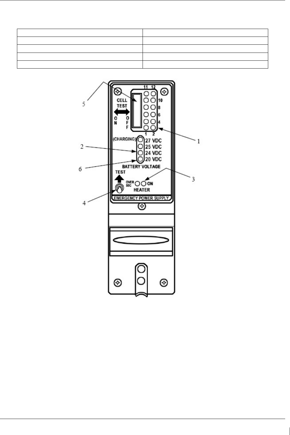
G1000/GFC700 System Maintenance Manual – C90A/C90GT/C90GTi King Air Page 4-37
190-00682-01 Revision G
Table 4-12, Standby Battery Required Equipment
DESCRIPTION VENDOR/SPECIFICATION
Power Supply 0-30 VDC, 20A capacity
DVM Fluke Model 8050A
Load Resistor 7Ω +/- 1% 250 watt
Stopwatch Capable of measuring to the minute
Figure 4-7, Standby Battery
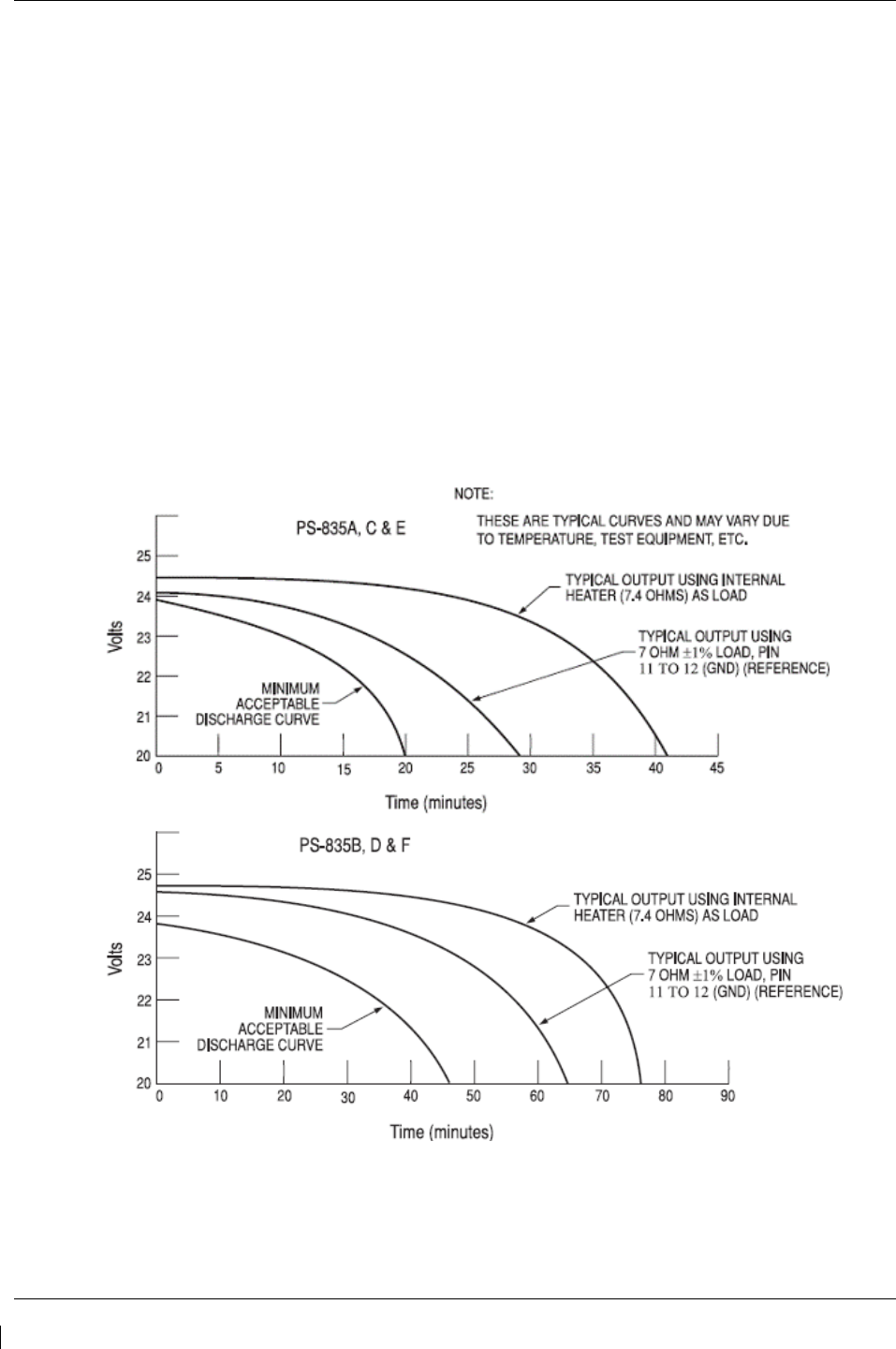
Page 4-38 G1000/GFC700 System Maintenance Manual – C90A/C90GT/C90GTi King Air
Revision G 190-00682-01
4.16.2 Capacity Test
NOTE
The PS-835 Emergency Power Supply must have completed a full charge prior to any
discharge testing. This test is performed with the battery removed from the aircraft.
A. Press and hold TEST SWITCH (Figure 4-7, Item 4) and observe the OUTPUT VOLTAGE
MONITOR LED's.
1) If the 24VDC OUTPUT VOLTAGE MONITOR LED comes on, proceed with Discharge Test
procedure.
2) If OUTPUT VOLTAGE MONITOR LED's do not come on, check fuses at bracket next to
battery and replace if blown. Perform Cell Isolation Test if no fuses are blown.
B. Discharge Test (Load Resistor)
1) Prepare for test by first constructing an X-Y graph similar to the one shown below. If possible,
use pre-printed graph paper to create a record of the discharge period along the X-axis and
voltage readings along the Y-axis.
2) Position all INDIVIDUAL CELL DIP SWITCHES (Figure 4-7, Item 5) to the ON position.
If the INDIVIDUAL CELL MONITOR LED DS12 is the only LED not illuminated, proceed to
the Cell Isolation Test.
3) Connect Digital Voltmeter leads to J1 connector pins 11 (+) and 7 (-).
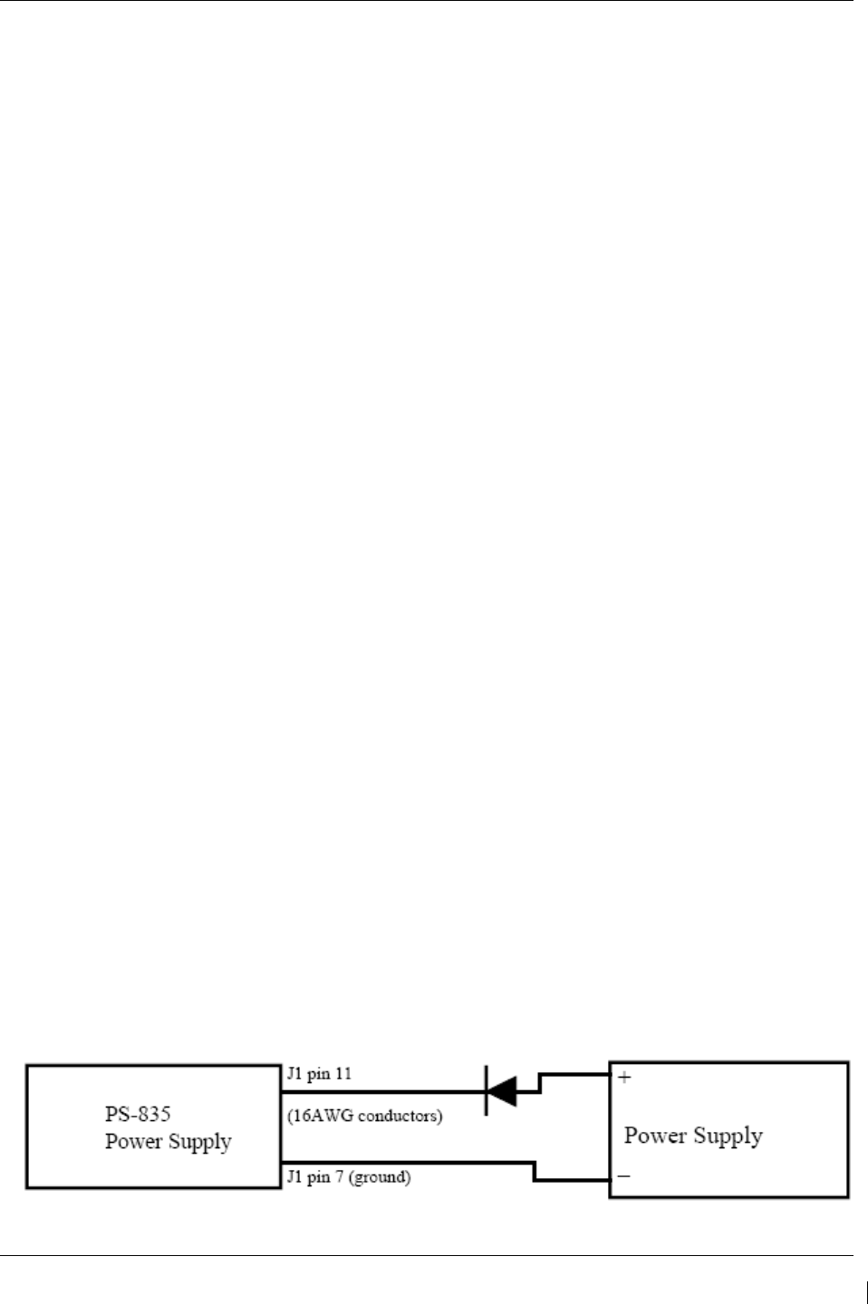
G1000/GFC700 System Maintenance Manual – C90A/C90GT/C90GTi King Air Page 4-39
190-00682-01 Revision G
4) Connect the Load Resistor across J1 connector pins 11 (+) and7 (-) and start timing the discharge
period with a stopwatch.
5) Monitor and plot voltage values at 10-minute intervals.
6) At 48.0 minutes note voltage on Digital Voltmeter. This voltage must be greater than 20.0 Vdc.
a. All INDIVIDUAL CELL MONITOR LED’s (Figure 4-7, Item 1) must remain on.
b. Any LED that does go OFF will represent a defective individual cell, which must be replaced.
7) Remove the Load Resistor from J1 connector pins 11 (+) and 7 (-).
8) Position all INDIVIDUAL CELL DIP SWITCHES (Figure 4-7, Item 5) to the OFF position.
9) Compare the voltage vs. time plot created during this test to that of curve identified as typical for the
External Load test method on the chart above. If the plot reveals a discharge curve that meets or
exceeds the MINIMUM ACCEPTABLE DISCHARGE CURVE, the unit is considered satisfactory.
10) If unit discharge plot is satisfactory and no other failures were revealed, perform the Charging
Procedure within 2 hours of completion of the discharge test. Return the unit into service.
4.16.3 Cell Isolation Test
NOTE
No power should be applied to PS-835 Emergency Power Supply during test. This test is
performed with the battery removed from the aircraft.
A. Press and hold TEST SWITCH (Figure 4-7, Item 4). If no OUTPUT VOLTAGE MONITOR LED's
come on:
1) Position all INDIVIDUAL CELL DIP SWITCHES (Figure 4-7, Item 5) to the ON position.
2) Press and hold TEST SWITCH (Figure 4-7, Item 4) and observe the INDIVIDUAL CELL
MONITOR LED's (Figure 4-7, Item 1).
a. If all INDIVIDUAL CELL MONITOR LED’s come on except DS12, the unit is damaged
and requires repair at an authorized repair station.
b. If all INDIVIDUAL CELL MONITOR LED’s are on, a low-battery voltage condition exists.
B. Perform the Charging Procedure.
4.16.4 Charging Procedure
(Constant-Voltage Charging Method)
Locally manufacture a power cable using 16AWG wire and the appropriate mating connector. Include a
Diode (15 Adc (min), 50.0 PIV or greater) to prevent battery discharge in case of loss of power from the
power source. Using the external power supply apply 30.0 Vdc (10A maximum current limited) to J1
connector pins 11 (+) and 7 (-) and charge the unit for 16 hours. The batteries should reach 80% capacity
within 1 hour and full charge at 16 hours.
Figure 4-8, Power Supply Connection

Page 4-40 G1000/GFC700 System Maintenance Manual – C90A/C90GT/C90GTi King Air
Revision G 190-00682-01
This page intentionally left blank.
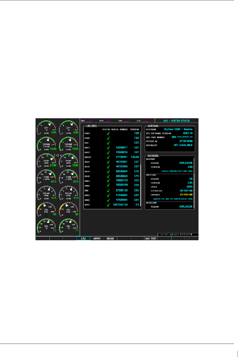
G1000/GFC700 System Maintenance Manual – C90A/C90GT/C90GTi King Air Page 5-1
190-00682-01 Revision G
5 TROUBLESHOOTING
This section provides instructions and guidance for G1000 system troubleshooting, as installed in the
King Air C90A/C90GT/C90GTi.
IMPORTANT!
Sections 6, 7 and 8 provide detailed instructions on equipment removal,
replacement, configuration, and return-to-service testing. Anytime a G1000
component or LRU is removed, swapped, or replaced, the technician must follow
the procedures given in Sections 6, 7 and 8 to ensure proper operation of the system.
Troubleshoot the G1000 system by first identifying, then isolating the specific failure to the responsible
LRU. There are several indications that the G1000 presents to the pilot or technician, showing overall
system condition. A course of action should be determined based on the information presented on the
display. This section shows possible scenarios likely to be encountered during normal operation and
gives troubleshooting guidance to the technician to resolve problems.
Figure 5-1. AUX – System Status Page
The AUX – System Status page displays the following information for each LRU and sub-function:
•
Status: A green checkmark (√) is displayed for properly operating LRUs. A red ‘x’ appears
when an internal LRU fault is detected and it has taken itself offline, or if the MFD cannot
communicate with the LRU.
•
Serial Number: Each LRU serial number is displayed (functions such as GPS and GS are
contained within an LRU; therefore, serial numbers are not shown for these).
•
Current SW Version Loaded.
When troubleshooting, first check to ensure that each LRU status is a green checkmark (√) and that the
correct software is loaded in each unit. Additional airframe and database information is also displayed on
this page.
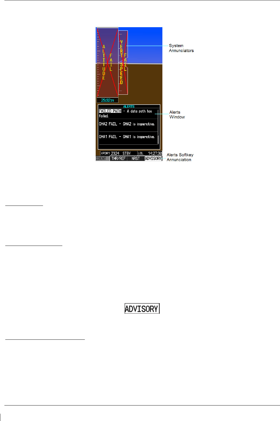
Page 5-2 G1000/GFC700 System Maintenance Manual – C90A/C90GT/C90GTi King Air
Revision G 190-00682-01
5.1 G1000 Alerting System
Figure 5-2. Alerts & Annunciations
The G1000 Alert System conveys alerts to the pilot using combinations of the following features:
Alert Window:
The Alert window displays alert text messages. Pressing the ALERTS softkey displays the Alerts
window. Pressing the ALERTS softkey again removes the Alerts window from the display.
Softkey Annunciation:
When the G1000 Alerting System issues an alert, the ALERTS softkey is used as a flashing annunciation
to accompany the alert. During the alert, the ALERTS softkey changes to ADVISORY as shown in
Figure 5-3. Pressing the softkey annunciation acknowledges the presence of the alert and displays the
advisory message in the Alerts Window.
Figure 5-3. ADVISORY Softkey Annunciation
System Failure Annunciations:
Typically, a large red X appears in windows when a failure is detected in the LRU providing the
information to the window.

G1000/GFC700 System Maintenance Manual – C90A/C90GT/C90GTi King Air Page 5-3
190-00682-01 Revision G
5.1.1 Aural & Audio Alerts
The G1000 system is capable of issuing audio and aural (voice) alerts for various situations. The
following alerts are utilized by the G1000:
Alert Name Purpose
Traffic (voice) TIS Traffic Advisory
No Traffic (voice) TIS Traffic Unavailable
“Minimums, Minimums” (voice) Minimums Aural Alert
Alt Alert Altitude Alerting Function
“Caution Terrain, Caution Terrain” (voice) and
“Terrain Ahead, Terrain Ahead” (voice)
TAWS Caution alert: Reduced required terrain
clearance
Or Imminent impact with terrain.
“Terrain Terrain, Pull Up Pull Up” (voice) and
“Terrain Ahead Pull Up, Terrain Ahead Pull Up”
TAWS Warning alert: Reduced required terrain
clearance
Or Imminent impact with terrain.
“Too Low Terrain” (voice) TAWS Caution alert: Premature descent alert (PDA)
“Sink Rate” (voice) TAWS Caution alert: Ground Proximity envelope 1, 2,
or 3, Excessive Descent Rate
“Pull Up” (voice) TAWS Warning alert: Ground Proximity envelope 1,
2, or 3, Excessive Descent Rate
“Don’t Sink” (voice) and
“Too Low Terrain”
TAWS Caution alert: Ground Proximity altitude loss
after takeoff
“Five Hundred” (voice) TAWS Caution alert: Ground proximity voice callout
“Caution Obstacle, Caution Obstacle” (voice) or
“Obstacle Ahead, Obstacle Ahead ” (voice) TAWS Caution alert: Obstacle awareness caution.
“Obstacle Obstacle Pull Up Pull Up” (voice) or
“Obstacle Ahead Pull Up, Obstacle Ahead Pull Up”
(voice)
TAWS Warning alert: Obstacle awareness warning.
“TAWS System Failure” (voice) TAWS status alert: Terrain failure
“TAWS Not Available” (voice) TAWS status alert: Terrain not available
“TAWS System Test, OK” (voice)(If passed) or
“TAWS System Failure” (voice) (If test failed) TAWS status alert: Terrain self-test
“TAWS Available” (voice) TAWS status alert: Terrain available
“Vertical Track” (voice) Vertical navigation alerting function
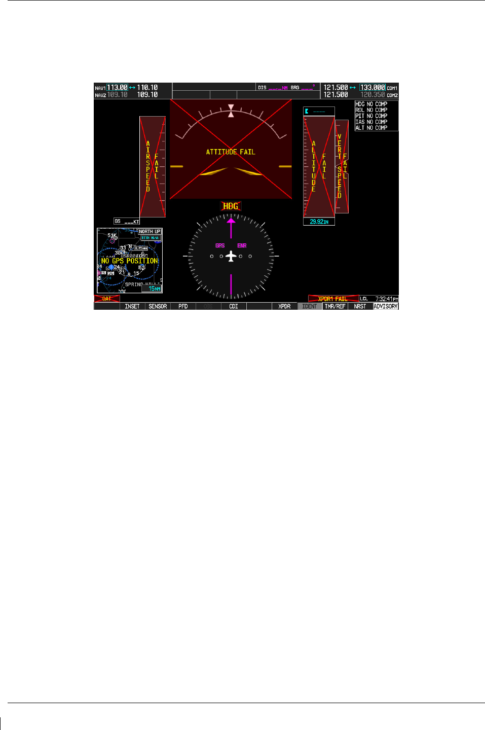
Page 5-4 G1000/GFC700 System Maintenance Manual – C90A/C90GT/C90GTi King Air
Revision G 190-00682-01
5.2 System Annunciations
If data fields become invalid due to an LRU failure, the PFD/MFD typically annunciates the failure with a
large red X, as shown in Figure 5-4.
Figure 5-4. System Annunciations
5.2.1 Failed Path Messages
The following message indicates there is a data path connected to the GDU (PFD1, PFD1, or MFD) or the
GIA 63W (1 or 2) that has failed.
FAILED PATH – A data path has failed.
The FAILED PATH message is triggered by a timeout of any one digital channel. The channels that are
checked are listed on these pages in config mode:
1) GDU RS-232 / ARINC 429 CONFIG (PFD1/2, and MFD)
2) GIA RS-232 / ARINC 429 CONFIG (GIA1 and GIA2)
3) GIA CAN / RS-485 CONFIGURATION (GIA1 and GIA2)
IMPORTANT!
Once the FAILED PATH message has been triggered, it will remain on the list of
messages until the next power cycle. This latching was implemented so that for
intermittent failures, the message would remain at the end of the flight (to alert
maintenance crew). Also, this keeps the crew from having to acknowledge message
repeatedly in the case of intermittent failures.
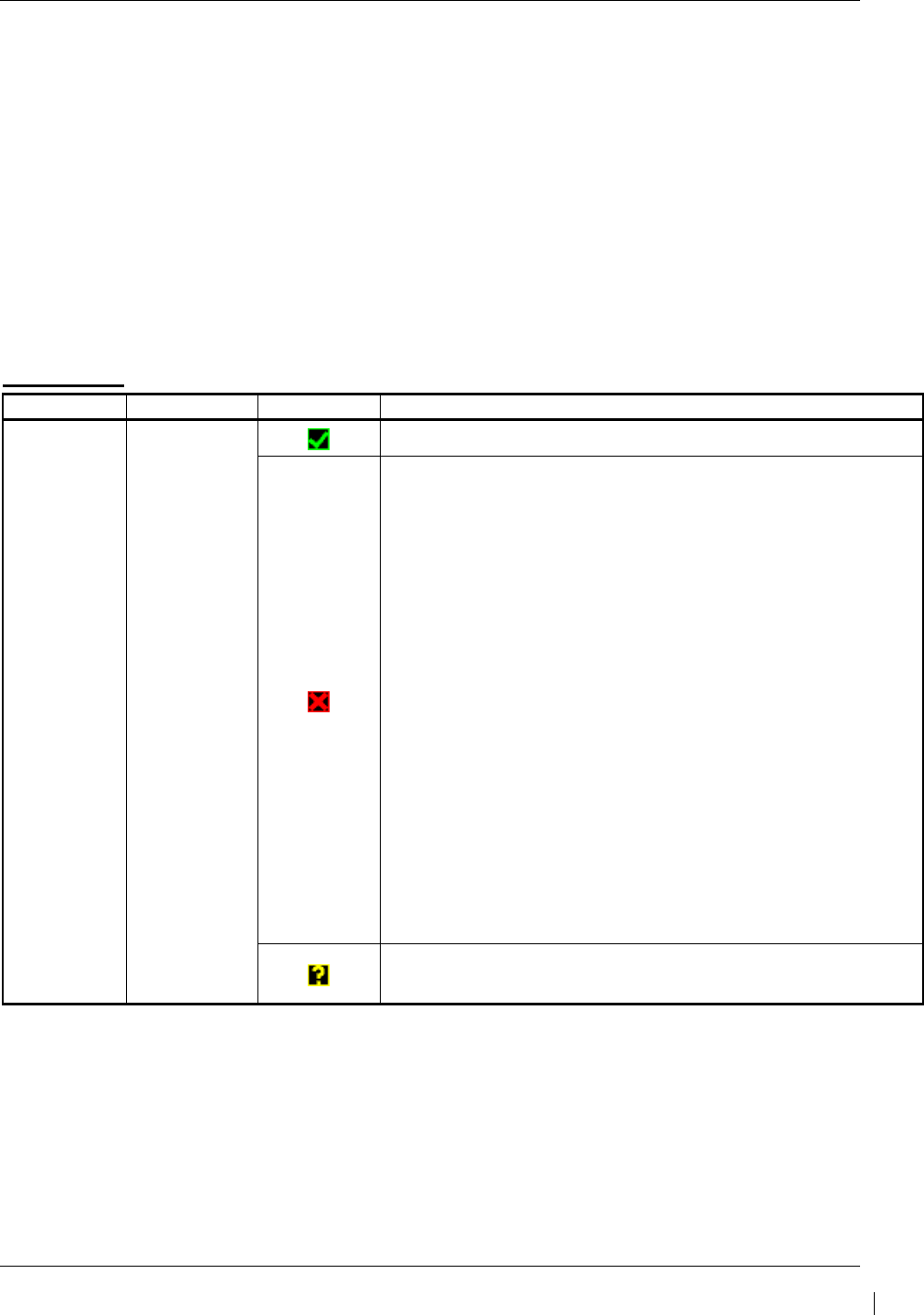
G1000/GFC700 System Maintenance Manual – C90A/C90GT/C90GTi King Air Page 5-5
190-00682-01 Revision G
NOTE
Reference Table 3-1 for interpretation of data indicator symbols
The box next to each channel indicates the current status of the channel per the below:
• Red X = data path is known to be failed
• Amber question mark (?) = data path status is unknown
• Green checkmark ()= data path is known to be good
The applicable data paths can be verified by viewing the configuration mode pages listed below.
5.2.1.1 GDU RS-232 / ARINC 429 CONFIG Page
PFD 1 RS-232
Channel LRU Indicator Status
CHNL 2 GMC 710
PFD1/GMC 710 data path is functioning correctly.
PFD1/GMC 710 data path is not functioning correctly.
• Verify GMC710 is powered on.
o If GMC 710 will not power on, remove unit and
verify power and ground are present at the GMC
connector.
If power or ground is not present,
troubleshoot aircraft wiring for faults.
If power and ground are present, replace
GMC 710.
• Load PFD1 and GMC 710 configuration files.
• Swap PFD1and PFD2 to confirm if the problem is in the
original PFD1.
o Replace original PFD1 if box turns to a green
checkmark (√) after swapping displays.
• Check the PFD1/GMC 710 interconnect wiring for faults.
Replace GMC 710 if problem remains.
PFD1/GMC 710 data path functionality is unknown. Reload
PFD1 configuration file.
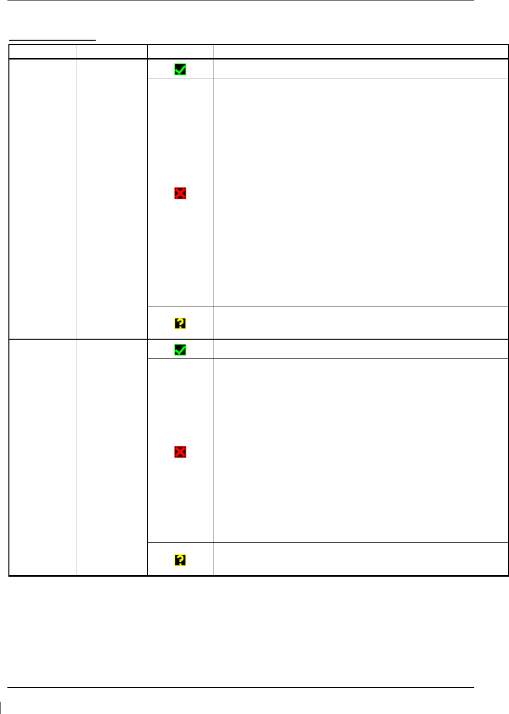
Page 5-6 G1000/GFC700 System Maintenance Manual – C90A/C90GT/C90GTi King Air
Revision G 190-00682-01
PFD 1 ARINC 429
Channel LRU Indicator Status
IN 1 GRS 77 #1
PFD1/GRS 77 #1 data path is functioning correctly.
PFD1/GRS 77 #1 data path is not functioning correctly.
• Verify GRS77 #1 status is “OK” using the System Status
page on the MFD. If it is not, correct condition before
proceeding, reference GRS troubleshooting sections.
• Load PFD1 configuration file.
• Swap PFD1 and PFD2 to confirm if the problem is in the
original PFD1.
o Replace original PFD1 if box turns to a green
checkmark (√) after swapping displays.
• Swap GRS1 and GRS2 (no reconfiguration required) to
confirm if the problem is in the original GRS1.
o Replace original GRS1 if box turns to a green
checkmark (√) after swapping units.
Check the PFD1/GRS 77 #1 interconnect wiring for faults.
PFD1/GRS 77 #1 data path functionally is unknown. Reload
PFD1 configuration file.
IN 2 GDC 74 #1
PFD1/GDC 74 #1 data path is functioning correctly
PFD1/GDC 74 #1 data path is not functioning correctly.
• Verify GDC 74 #1 status is “OK” using the System Status
page on the MFD. If it is not, correct condition before
proceeding, reference GDC troubleshooting sections.
• Load PFD1 and GDC 74 #1 configuration files.
• Swap PFD1 and PFD2 to confirm if the problem is in the
original PFD1.
o Replace original PFD1 if box turns to a green
checkmark (√) after swapping displays.
• Check the PFD1/GDC 74 #1 interconnect wiring for faults.
Replace GDC 74 #1 if problem remains.
PFD1/GDC 74 #1 data path functionality is unknown. Reload
PFD1 configuration file.
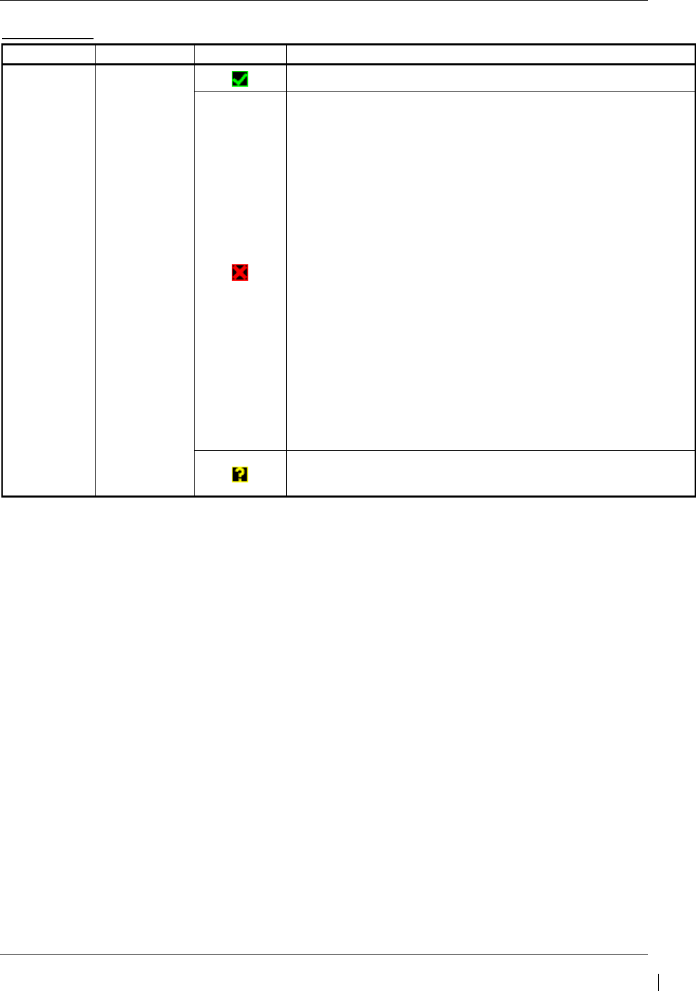
G1000/GFC700 System Maintenance Manual – C90A/C90GT/C90GTi King Air Page 5-7
190-00682-01 Revision G
PFD 2 RS-232
Channel LRU Indicator Status
CHNL 2 GMC 710
PFD2/GMC 710 data path is functioning correctly.
PFD2/GMC 710 data path is not functioning correctly.
• Verify GMC 710 is powered on.
o If GMC 710 will not power on, remove unit and
verify power and ground are present at the GMC
connector.
If power or ground is not present,
troubleshoot aircraft wiring for faults.
If power and ground are present, replace
GMC 710.
• Load PFD2 and GMC 710 configuration files.
• Swap PFD2 and PFD1 to confirm if the problem is in the
original PFD2.
o Replace original PFD2 if box turns to a green
checkmark (√) after swapping displays.
• Check the PFD2/GMC 710 interconnect wiring for faults.
Replace GMC 710 if problem remains.
PFD2/GMC 710 data path functionality is unknown. Reload
PFD2 configuration file.
Page 5-8 G1000/GFC700 System Maintenance Manual – C90A/C90GT/C90GTi King Air
Revision G 190-00682-01
PFD 2 ARINC 429
Channel LRU Indicator Status
IN 1 GRS 77 #2
PFD2/GRS 77 #2 data path is functioning correctly.
PFD2/GRS 77 #2 data path is not functioning correctly.
• Verify GRS77 #2 status is “OK” using the System Status
page on the MFD. If it is not, correct condition before
proceeding, reference GRS troubleshooting sections.
• Load PFD2 configuration file.
• Swap PFD2 and PFD1 to confirm if the problem is in the
original PFD2.
o Replace original PFD2 if box turns to a green
checkmark (√) after swapping displays.
• Swap GRS1 and GRS2 (no reconfiguration required) to
confirm if the problem is in the original GRS1.
o Replace original GRS1 if box turns green after
swapping units.
• Check the PFD2/GRS 77 #2 interconnect wiring for faults.
PFD2/GRS 77 #2 data path functionality is unknown. Reload
PFD2 configuration file.
IN 2 GDC 74 #2
PFD2/GDC 74 #2 data path is functioning correctly.
PFD2/GDC 74 #2 data path is not functioning correctly.
• Verify GDC 74 #2 status is “OK” using the System Status
page on the MFD. If it is not, correct condition before
proceeding, reference GDC troubleshooting sections.
• Load PFD2 and GDC 74 #2 configuration files.
• Swap PFD2 and PFD1 to confirm if the problem is in the
original PFD2.
o Replace original PFD2 if box turns to a green
checkmark (√) after swapping displays.
• Check the PFD2/GDC 74 #2 interconnect wiring for faults.
Replace GDC 74 #2 if problem remains.
PFD2/GDC 74 #2 data path functionality is unknown. Reload
PFD2 configuration file.
G1000/GFC700 System Maintenance Manual – C90A/C90GT/C90GTi King Air Page 5-9
190-00682-01 Revision G
MFD1 RS-232
Channel LRU Indicator Status
CHNL 1 GCU 475
MFD1/GCU 475 data path is functioning correctly.
MFD1/GCU 475 data path is not functioning correctly.
• Verify GCU 475 is powered on.
o If GCU 475 will not power on, remove unit and
verify power and ground are present at the GCU
connector.
If power or ground is not present,
troubleshoot aircraft wiring for faults.
If power and ground are present, replace
GCU 475.
• Load MFD1 and GCU 475 configuration files.
• Check the MFD1/GCU 475 interconnect wiring for faults.
• Replace GCU 475.
Replace MFD if problem remains.
MFD1/GCU data path functionality is unknown. Reload MFD1
configuration file.
Page 5-10 G1000/GFC700 System Maintenance Manual – C90A/C90GT/C90GTi King Air
Revision G 190-00682-01
5.2.1.2 GIA RS-232 / ARINC 429 CONFIG Page
GIA1 RS-232
Channel LRU Indicator Status
CHNL 1 GDC 74 #1
GIA1/GDC 74 #1 data path is functioning correctly.
GIA1/GDC 74 #1 data path is not functioning correctly.
• Load GIA1 and GDC 74 #1 configuration files.
• Swap GIA1 and GIA2, reconfigure both GIA’s to their new
locations to confirm if the problem is in the original GIA1.
o Replace original GIA1 if box turns to a green
checkmark (√) after swapping units.
• Check the GIA1/GDC 74 #1 interconnect wiring for faults.
Replace GDC 74 #1 if problem remains.
GIA1/GDC 74 #1 data path functionality is unknown. Reload
GIA1 configuration files.
CHNL 2 GRS 77 #2
(output only) GIA1/GRS 77 #2 output data path is not monitored. A black
box N/A is normal.
G1000/GFC700 System Maintenance Manual – C90A/C90GT/C90GTi King Air Page 5-11
190-00682-01 Revision G
CHNL 5 GTX 33D #1
w/TIS
GIA1/GTX 33 #1 data path is functioning correctly.
GIA1/GTX 33 #1 data path is not functioning correctly.
• Load GIA1 and GTX 33 #1 configuration files.
• Swap GIA1 and GIA2, reconfigure both GIA’s to their new
locations to confirm if the problem is in the original GIA1.
o Replace original GIA1 if box turns to a green
checkmark (√) after swapping units.
• Check the GIA1/GTX 33 #1 interconnect wiring for faults.
Replace GTX 33 #1 if problem remains.
GIA1/GTX 33D #1 data path functionality is unknown. Reload
GIA1 configuration files.
CHNL 6 GRS 77 #1
GIA1/GRS 77 #1 data path is functioning correctly.
GIA1/GRS 77 #1 data path is not functioning correctly.
• Load GIA1 configuration files.
• Swap GIA1 and GIA2, reconfigure both GIA’s to their new
locations to confirm if the problem is in the original GIA1.
o Replace original GIA1 if box turns to a green
checkmark (√) after swapping units.
• Swap GRS1 and GRS2 (no reconfiguration required) to
confirm if the problem is in the original GRS1.
o Replace original GRS1 if box turns to a green
checkmark (√) after swapping units.
Check the GIA1/GRS 77 #1 interconnect wiring for faults.
GIA1/GRS 77 #1 data path functionality is unknown. Reload
GIA1 configuration files.
CHNL 7 GMA
1347D #1
GIA1/GMA 1347D #1 data path is functioning correctly.
GIA1/GMA 1347D #1 data path is not functioning correctly.
• Load GIA1 and GMA 1347 #1 configuration files.
• Swap GMA 1347D #1 and GMA 1347D #2, reconfigure
both GMA’s to their new locations, to confirm if the
problem is in the original GMA 1347D #1.
o Replace original GMA 1347D #1 if box turns to a
green checkmark (√) after swapping units.
• Swap GIA1 and GIA2, reconfigure both GIA’s to their new
locations to confirm if the problem is in the original GIA1.
o Replace original GIA1 if box turns to a green
checkmark (√) after swapping units.
Check the GIA1/GMA 1347D #1 interconnect wiring for faults.
GIA1/GMA 1347D #1 data path functionality is unknown.
Reload GIA1 configuration files.
Page 5-12 G1000/GFC700 System Maintenance Manual – C90A/C90GT/C90GTi King Air
Revision G 190-00682-01
GIA1 ARINC 429
Channel LRU Indicator Status
IN 2
(applies only
with SW Image
0636.03 and
subs)
GRS 77 #2
GIA1/GRS 77 #2 data path is functioning correctly.
GIA1/ GRS 77 #2 data path is not functioning correctly.
• Load GIA1 configuration file.
• Swap GIA1 and GIA2, reconfigure both GIA’s to their new
locations to confirm if the problem is in the original GIA1.
o Replace original GIA1 if box turns to a green
checkmark (√) after swapping units.
• Swap GRS1 and GRS2 (no reconfiguration required) to
confirm if the problem is in the original GRS2.
o Replace original GRS2 if box turns to a green
checkmark (√) after swapping units.
• Check the GIA1/ GRS 77 #2 interconnect wiring for faults.
GIA1/ GRS 77 #2 data path functionality is unknown. Reload
GIA1 configuration files.
IN 5 GDC 74 #1
GIA1/GDC 74 #1 data path is functioning correctly.
GIA1/GDC 74 #1 data path is not functioning correctly.
• Load GIA1 and GDC 74 #1 configuration files.
• Swap GIA1 and GIA2, reconfigure both GIA’s to their new
locations to confirm if the problem is in the original GIA1.
o Replace original GIA1 if box turns to a green
checkmark (√) after swapping units.
• Check the GIA1/GDC 74 #1 interconnect wiring for faults.
Replace GDC 74 #1 if problem remains.
GIA1/GDC 74 #1 data path functionality is unknown. Reload
GIA1 configuration files.
G1000/GFC700 System Maintenance Manual – C90A/C90GT/C90GTi King Air Page 5-13
190-00682-01 Revision G
IN 6 GRS 77 #1
GIA1/GRS 77 #1 data path is functioning correctly.
GIA1/GRS 77 #1 data path is not functioning correctly.
• Load GIA1 configuration files.
• Swap GIA1 and GIA2, reconfigure both GIA’s to their new
locations to confirm if the problem is in the original GIA1.
o Replace original GIA1 if box turns to a green
checkmark (√) after swapping units.
• Swap GRS1 and GRS2 (no reconfiguration required, ref.
GRS Configuration and Testing sections) to confirm if the
problem is in the original GRS1.
o Replace original GRS1 if box turns to a green
checkmark (√) after swapping units.
Check the GIA1/GRS 77 #1 interconnect wiring for faults.
GIA1/GRS 77 #1 data path functionality is unknown. Reload
GIA1 configuration files.
Page 5-14 G1000/GFC700 System Maintenance Manual – C90A/C90GT/C90GTi King Air
Revision G 190-00682-01
GIA2 RS-232
Channel LRU Indicator Status
CHNL 1 GDC 74B #2
GIA2/GDC 74 #2 data path is functioning correctly.
GIA2/GDC 74 #2 data path is not functioning
correctly.
• Load GIA2 and GDC 74 #2 configuration files.
• Swap GIA2 and GIA1, reconfigure both GIA’s to
their new locations to confirm if the problem is in
the original GIA1.
o Replace original GIA2 if box turns to a
green checkmark (√) after swapping units.
• Check the GIA1/GDC 74 #2 interconnect wiring
for faults.
Replace GDC 74 #2 if problem remains.
GIA2/GDC 74B #2 data path functionality is unknown.
Reload GIA2 configuration files.
CHNL 2 GRS 77 #1 (output only) GIA2/GRS 77 #1 output data path is not monitored. A
black N/A box is normal.
CHNL 5 GTX 33/33D #2 w/TIS
GIA2/GTX 33 #2 data path is functioning correctly.
GIA2/GTX 33 #2 data path is not functioning
correctly.
• Load GIA2 and GTX 33 #2 configuration files.
• Swap GIA2 and GIA1, reconfigure both GIA’s to
their new locations to confirm if the problem is in
the original GIA1.
o Replace original GIA2 if box turns to a
green checkmark (√) after swapping units.
• Check the GIA2/GTX 33/33D #2 interconnect
wiring for faults.
Replace GTX 33/33D #2 if problem remains.
GIA2/GTX 33 #2 data path functionality is unknown.
Reload GIA2 configuration files.
G1000/GFC700 System Maintenance Manual – C90A/C90GT/C90GTi King Air Page 5-15
190-00682-01 Revision G
CHNL 6 GRS 77 #2
GIA2/GRS 77 #2 data path is functioning correctly.
GIA2/GRS 77 #2 data path is not functioning correctly.
• Load GIA2 configuration files.
• Swap GIA2 and GIA1, reconfigure both GIA’s to their new
locations to confirm if the problem is in the original GIA1.
o Replace original GIA2 if box turns to a green
checkmark (√) after swapping units.
• Swap GRS2 and GRS1 (no reconfiguration required) to
confirm if the problem is in the original GRS2.
o Replace original GRS2 if box turns to a green
checkmark (√) after swapping units.
Check the GIA2/GRS 77 #2 interconnect wiring for faults.
GIA2/GRS 77 #2 data path functionality is unknown. Reload
GIA2 configuration files.
CHNL 7 GMA
1347D #2
GIA2/GMA 1347D #2 data path is functioning correctly.
GIA2/GMA 1347D #2 data path is not functioning correctly.
• Load GIA2 and GMA 1347D #2 configuration files.
• Swap GMA 1347D #2 and GMA 1347D #1, reconfigure
both GMA’s to their new locations to confirm if the problem
is in the original GMA 1347D #2.
o Replace original GMA 1347D #2 if box turns to a
green checkmark (√) after swapping units.
• Swap GIA2 and GIA1, reconfigure both GIA’s to their new
locations to confirm if the problem is in the original GIA2.
o Replace original GIA2 if box turns to a green
checkmark (√) after swapping units.
Check the GIA1/GMA 1347 #2 interconnect wiring for faults.
GIA1/GMA 1347D #2 data path functionality is unknown.
Reload GIA2 configuration files.

Page 5-16 G1000/GFC700 System Maintenance Manual – C90A/C90GT/C90GTi King Air
Revision G 190-00682-01
GIA2 ARINC 429
Channel LRU Indicator Status
IN 2
(applies only
with SW Image
0636.03 and
subs)
GRS 77 #1
GIA2/GRS 77 #1 data path is functioning correctly.
GIA2/ GRS 77 #1 data path is not functioning correctly.
• Load GIA2 configuration file.
• Swap GIA1 and GIA2, reconfigure both GIA’s to their new
locations to confirm if the problem is in the original GIA2.
o Replace original GIA2 if box turns to a green
checkmark (√) after swapping units.
• Swap GRS1 and GRS2 (no reconfiguration required) to
confirm if the problem is in the original GRS1.
o Replace original GRS1 if box turns to a green
checkmark (√) after swapping units.
• Check the GIA2/ GRS 77 #1 interconnect wiring for faults.
GIA2/ GRS 77 #1 data path functionality is unknown. Reload
GIA2 configuration files.
IN 5 GDC 74 #2
GIA2/GDC 74 #2 data path is functioning correctly.
GIA2/GDC 74 #2 data path is not functioning correctly.
• Load GIA2 and GDC 74 #2 configuration files.
• Swap GIA2 and GIA1, reconfigure both GIA’s to their new
locations to confirm if the problem is in the original GIA2.
o Replace original GIA2 if box turns to a green
checkmark (√) after swapping units.
• Check the GIA2/GDC 74 #2 interconnect wiring for faults.
Replace GDC 74 #2 if problem remains.
GIA2/GDC 74 #2 data path functionality is unknown. Reload
GIA2 configuration files.
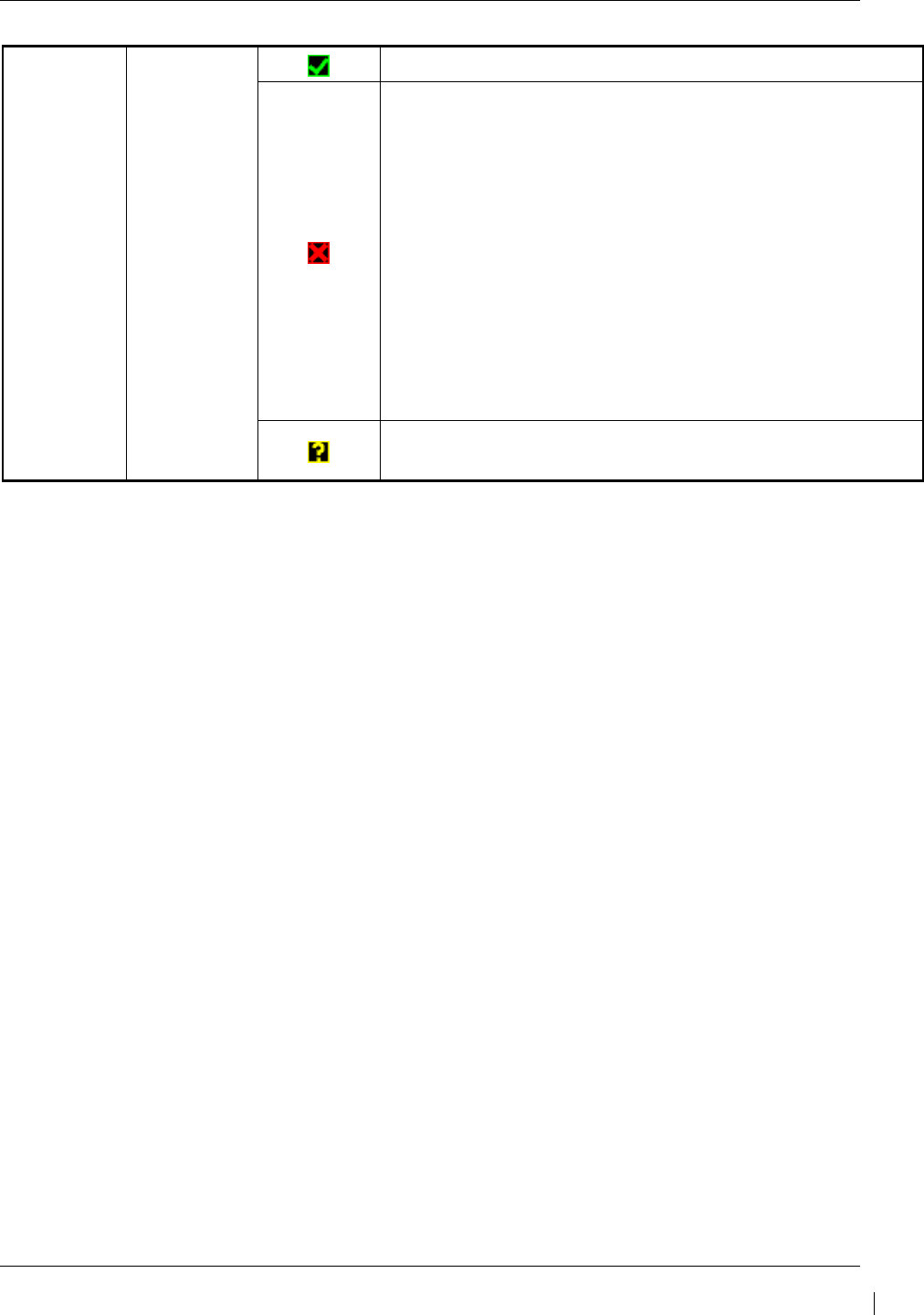
G1000/GFC700 System Maintenance Manual – C90A/C90GT/C90GTi King Air Page 5-17
190-00682-01 Revision G
IN 6 GRS 77 #2
GIA2/GRS 77 #2 data path is functioning correctly.
GIA2/GRS 77 #2 data path is not functioning correctly.
• Load GIA2 configuration files.
• Swap GIA2 and GIA1, reconfigure both GIA’s to their new
locations to confirm if the problem is in the original GIA2.
o Replace original GIA2 if box turns to a green
checkmark (√) after swapping units.
• Swap GRS2 and GRS1 (no reconfiguration required) to
confirm if the problem is in the original GRS2.
o Replace original GRS2 if box turns to a green
checkmark (√) after swapping units.
Check the GIA2/GRS 77 #2 interconnect wiring for faults.
GIA2/GRS 77 #2 data path functionality is unknown. Reload
GIA2 configuration files.
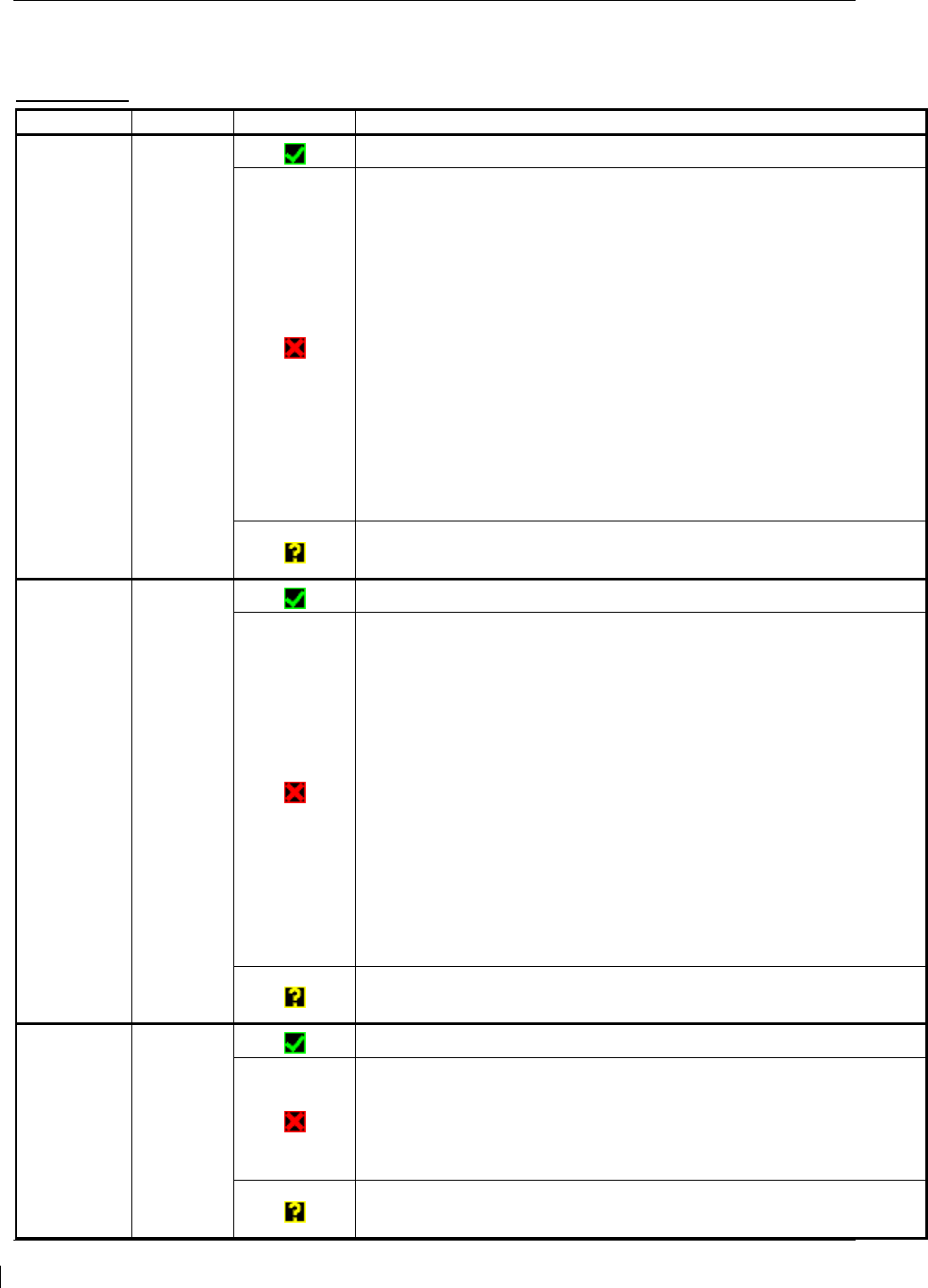
Page 5-18 G1000/GFC700 System Maintenance Manual – C90A/C90GT/C90GTi King Air
Revision G 190-00682-01
5.2.1.3 GIA CAN / RS-485 CONFIGURATION Page
GIA1 RS-485
Channel LRU Indicator Status
CHNL 1 GEA1
GIA1/GEA1 data path is functioning correctly.
GIA1/GEA1 data path is not functioning correctly.
• Verify GEA1 is powered on using the GEA Status page.
• Load GIA1 and GEA1 configuration files.
• Swap GIA1 and GIA2, reconfigure both GIA’s to their new
locations to confirm if the problem is in the original GIA1.
o Replace original GIA1 if box turns to a green checkmark
(√) after swapping units.
• Swap GEA1 and GEA2, reconfigure both GEA’s to their new
locations to confirm if the problem is in the original GEA1.
o Replace original GEA1 if box turns to a green checkmark
(√) after swapping units.
Check the GIA1/GEA1 interconnect wiring for faults.
GIA1/GEA1 data path functionality is unknown. Reload GIA1
configuration files.
CHNL 2 GEA2
GIA1/GEA2 data path is functioning correctly.
GIA1/GEA2 data path is not functioning correctly.
• Verify GEA2 is powered on using the GEA Status page.
• Load GIA1 and GEA2 configuration files.
• Swap GIA1 and GIA2, reconfigure both GIA’s to their new
locations to confirm if the problem is in the original GIA1.
o Replace original GIA1 if box turns to a green checkmark
(√) after swapping units.
• Swap GEA2 and GEA1, reconfigure both GEA’s to their new
locations to confirm if the problem is in the original GEA2.
o Replace original GEA2 if box turns to a green checkmark
(√) after swapping units.
Check the GIA1/GEA2 interconnect wiring for faults.
GIA1/GEA2 data path functionality is unknown. Reload GIA1
configuration files.
CHNL 4 GFC 700
GIA1/GFC 700 data path is functioning correctly.
GIA1/GFC 700 data path is not functioning correctly.
• Load GIA1 configuration files, GIA Gains file and GSA software
and gains file (if LRU and Card versions are different).
Reference GFC section for further troubleshooting.
GIA1/GFC 700 data path functionality is unknown. Reload GIA1
configuration files.
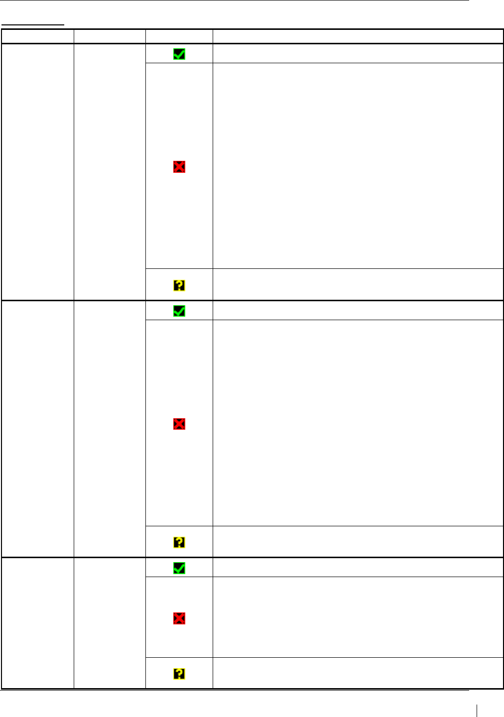
G1000/GFC700 System Maintenance Manual – C90A/C90GT/C90GTi King Air Page 5-19
190-00682-01 Revision G
GIA2 RS-485
Channel LRU Indicator Status
CHNL 1 GEA1
GIA2/GEA1 data path is functioning correctly.
GIA2/GEA1 data path is not functioning correctly.
• Verify GEA1 is powered on using the GEA Status page.
• Load GIA2 and GEA1 configuration files.
• Swap GIA2 and GIA1, reconfigure both GIA’s to their new
locations to confirm if the problem is in the original GIA2.
o Replace original GIA2 if box turns to a green
checkmark (√) after swapping units.
• Swap GEA1 and GEA2, reconfigure both GEA’s to their
new locations to confirm if the problem is in the original
GEA1.
o Replace original GEA1 if box turns to a green
checkmark (√) after swapping units.
Check the GIA2/GEA1 interconnect wiring for faults.
GIA2/GEA1 data path functionality is unknown. Reload GIA2
configuration files.
CHNL 2 GEA2
GIA2/GEA2 data path is functioning correctly.
GIA2/GEA2 data path is not functioning correctly.
• Verify GEA2 is powered on using the GEA Status page.
• Load GIA2 and GEA2 configuration files.
• Swap GIA2 and GIA1, reconfigure both GIA’s to their new
locations to confirm if the problem is in the original GIA2.
o Replace original GIA2 if box turns to a green
checkmark (√) after swapping units.
• Swap GEA2 and GEA1, reconfigure both GEA’s to their
new locations to confirm if the problem is in the original
GEA2.
o Replace original GEA2 if box turns to a green
checkmark (√) after swapping units.
Check the GIA2/GEA2 interconnect wiring for faults.
GIA2GEA2 data path functionality is unknown. Reload GIA2
configuration files.
CHNL 4 GFC 700
GIA2/GFC 700 data path is functioning correctly.
GIA2/GFC 700 data path is not functioning correctly.
• Load GIA2 configuration files, GIA Gains file and GSA
software and gains file (if LRU and Card versions are
different).
Reference GFC section for further troubleshooting.
GIA2/GFC 700 data path functionality is unknown. Reload
GIA2 configuration files.
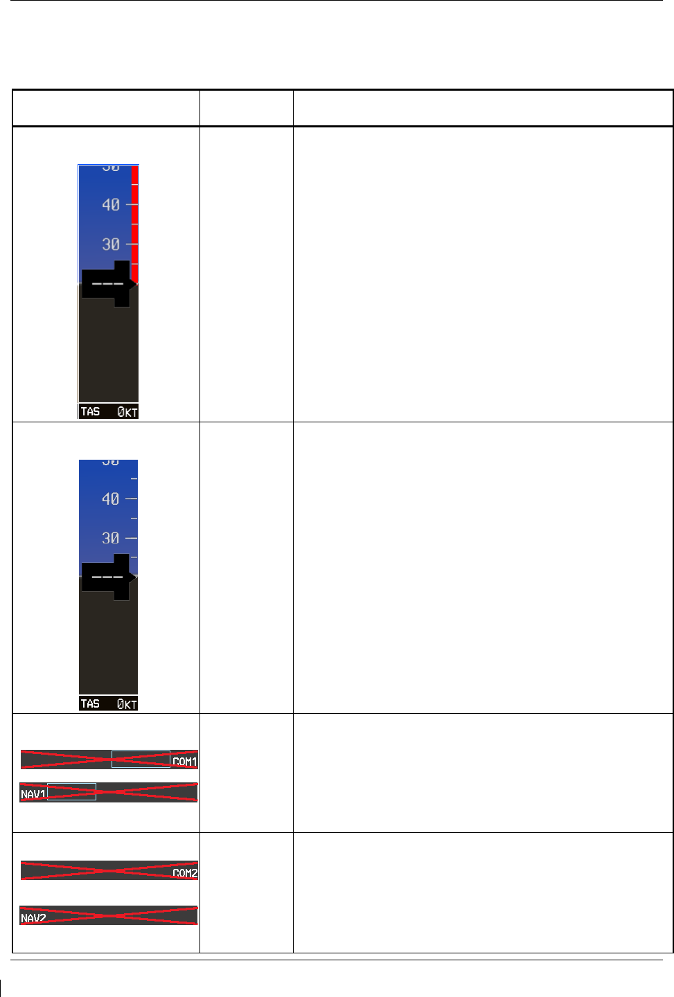
Page 5-20 G1000/GFC700 System Maintenance Manual – C90A/C90GT/C90GTi King Air
Revision G 190-00682-01
5.2.2 System Failure Troubleshooting
The following table provides basic troubleshooting guidance for LRU failures. Refer to G1000/GFC 700
Wiring Diagram, listed in Table 1-2, as needed to verify interconnects.
Invalid Data Field Associated
LRU(s) Solution
Low Speed Awareness Band
permanently displayed
GDU
NOTE
Reference Table 3-1 for interpretation of data
indicator symbols
• With aircraft weight on wheels and the G1000 in
Configuration Mode, check that the RH GEAR ON
GROUND Discrete In indication on GIA I/O
CONFIGURATION page is VALID or TRUE.
• If indication is VALID or TRUE, switch GIA1 and GIA2,
to verify location of problem:
If problem is resolved, replace defective unit.
If indication is INVALID or FALSE, check for wiring
faults between the GIAs and aircraft squat switch
system.
Low Speed Awareness Band
permanently inhibited
GDU
NOTE
Reference Table 3-1 for interpretation of data
indicator symbols
• With aircraft weight off wheels and the G1000 in
Configuration Mode, check that the RH GEAR ON
GROUND Discrete In indication on GIA I/O
CONFIGURATION page is INVALID or FALSE.
• If indication is INVALID or FALSE, switch GIA1 and
GIA2, to verify location of problem:
If problem is resolved, replace unit.
If indication is VALID or TRUE, check for wiring
faults between the GIAs and aircraft squat switch
system.
NAV1 & COM1
GIA1
• Check configuration settings for GIA1 and PFD1.
• Swap GIA1 and GIA2, to verify location of problem:
If problem follows GIA1, replace GIA1.
• Check Ethernet interconnect from GIA1 to PFD1.
If problem persists, replace PFD.
NAV2 & COM2
GIA2
• Check configuration settings for GIA2 and PFD2.
• Swap GIA1 and GIA2, to verify location of problem:
If problem follows GIA2, replace GIA2.
• Check Ethernet interconnect from GIA2 to PFD2.
If problem persists, replace PFD.
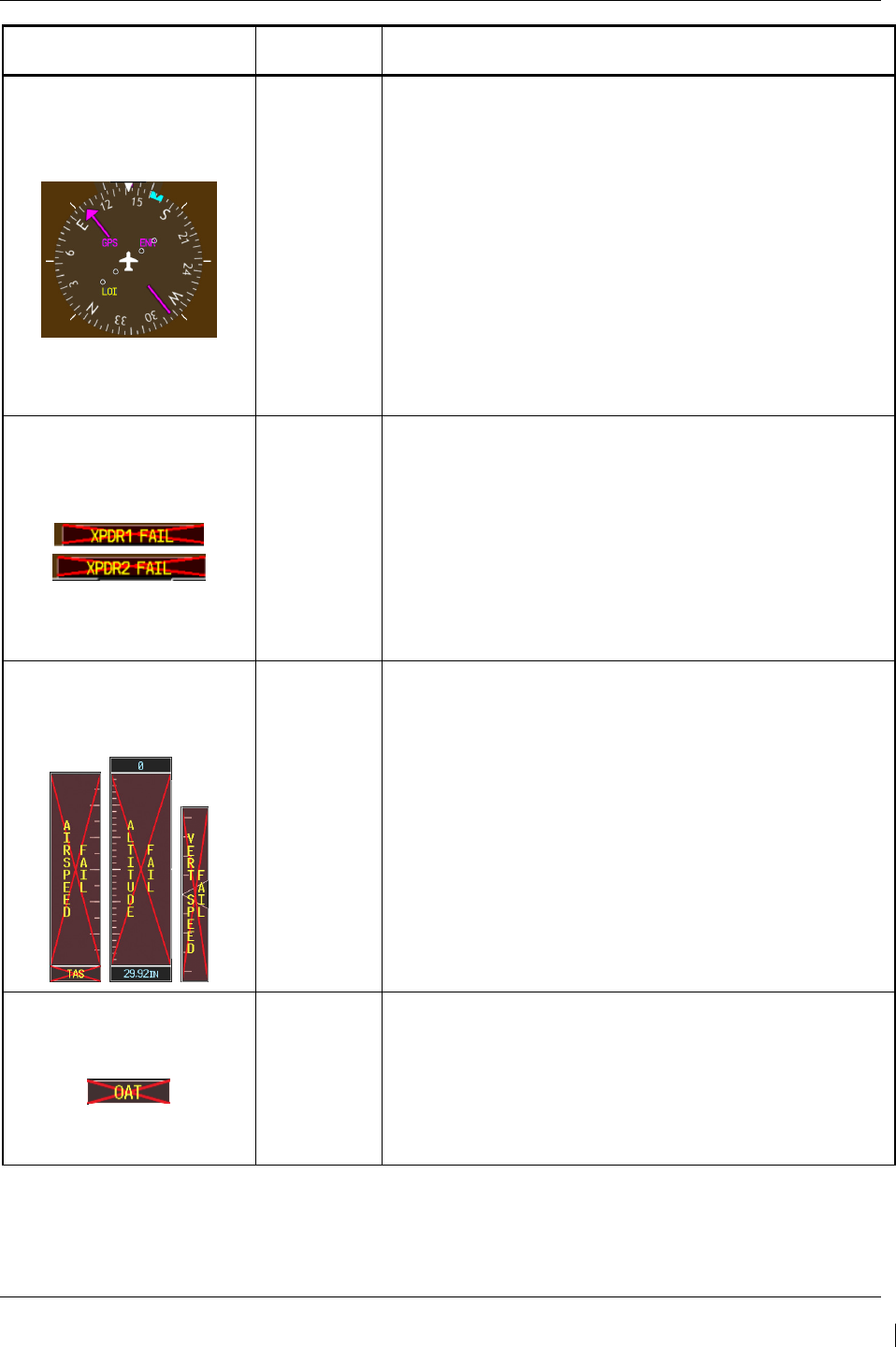
G1000/GFC700 System Maintenance Manual – C90A/C90GT/C90GTi King Air Page 5-21
190-00682-01 Revision G
Invalid Data Field Associated
LRU(s) Solution
GPS LOI
GIA1 or GIA2
• Ensure that a cell phone or a device using cell phone
technology is not turned on (even in a monitoring state)
in the cabin.
• Check GPS1 and GPS2 signal strength on AUX
page 4. Refer to GIA GPS section if GPS cannot
acquire a position lock for troubleshooting.
• Check corresponding GPS antenna and cable for
faults.
• Check Ethernet interconnect between the PFD1 to
GIA1 or PFD2 to GIA2 for faults.
• Swap GIA1 and GIA2, to verify location of problem:
If problem follows the GIA, replace the GIA.
If problem persists, replace the PFD1 or PFD2.
XPDR FAIL
GTX 33
• Check GTX 33 configuration settings for GIA1 and
GIA2.
• Check GTX 33/GIA1 interconnect.
• Check GTX 33/GIA2 interconnect.
• Perform a SET>ACTV configuration reset on the GTX
Config page for each GTX, and verify the aircraft
registration is present.
• Replace GTX 33.
If problem persists, replace GIA.
TAS FAIL
AIRSPEED FAIL
ALTITUDE FAIL
VERT SPEED FAIL
GDC 74B
Inspect GDC 74B pitot/static plumbing integrity.
Inspect pitot/static ports and associated equipment for
faults.
For TAS failure, also check GTP 59 probe.
Check GDC 74B configuration settings for the PFDs,
MFD, GIA1, and GIA2.
1. If PFDs, MFD, and GIA configuration settings are
correct, replace the GDC configuration module.
If problem persists, replace the GDC 74B.
OAT
GTP 59
• Check OAT probe wiring and connectors for faults.
• Check GDC config module wiring for damage, replace
if any is found.
• Replace GDC config module
• Replace GDC 74B with a known good unit:
If problem persists, replace the GTP 59.
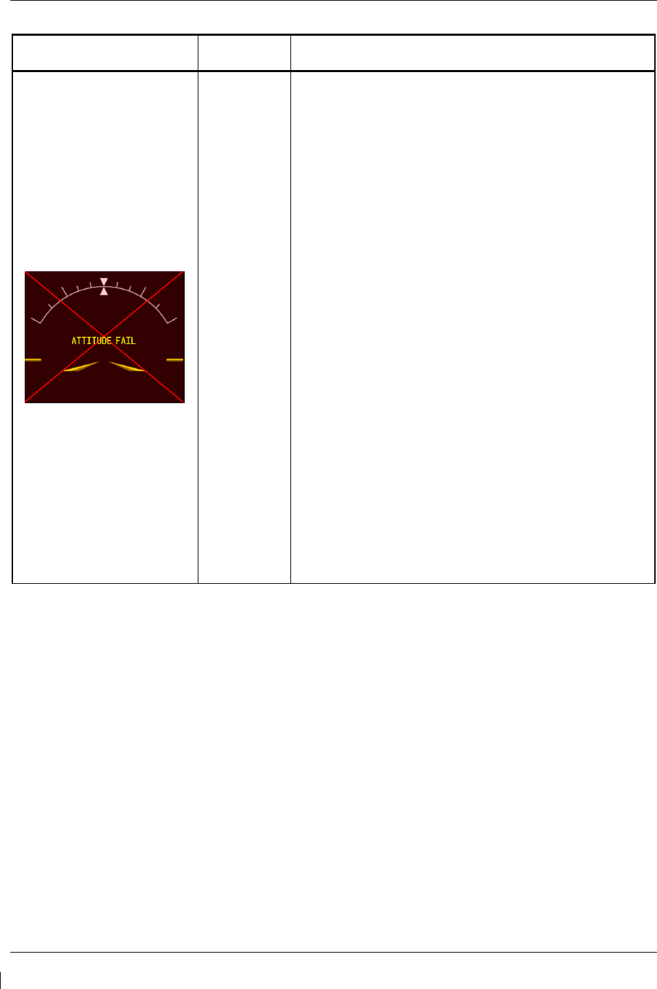
Page 5-22 G1000/GFC700 System Maintenance Manual – C90A/C90GT/C90GTi King Air
Revision G 190-00682-01
Invalid Data Field Associated
LRU(s) Solution
ATTITUDE FAIL
GRS 77
• Ensure that a cell phone or a device using cell phone
technology is not turned on (even in a monitoring
state) in the cabin.
• Cycle GRS 77 power to restart initialization.
• Ensure GRS 77 connecter is secure and proper wire
harness strain relief is provided.
• Ensure the GRS 77 is fastened down tightly in its
mounting rack and that the mounting rack is not
loose (CAUTION - do not loosen the mounting rack
hardware to the airframe shelf or the aircraft will need
to be re-leveled and the PITCH/ROLL OFFSET
procedure performed).
• Ensure GPS has acquired at least four satellites, has
a 3D navigation solution, and a DOP of less than 5.0.
This is particularly important for an ATTITUDE FAIL
that appears during ground operation only.
• Perform an Engine Run-Up Test to check if engine
vibration is causing the GRS 77 to go offline.
• Load configuration files to the PFD, MFD, GIA1, and
GIA2.
• Calibrate the GRS 77 (Pitch/Roll Offset and
Magnetometer Calibration).
• Replace GRS 77.
If problem persists replace GRS 77 configuration
module.
Contact Garmin Aviation Product Support if
condition continues after replacing the GRS 77
and config module for additional assistance.
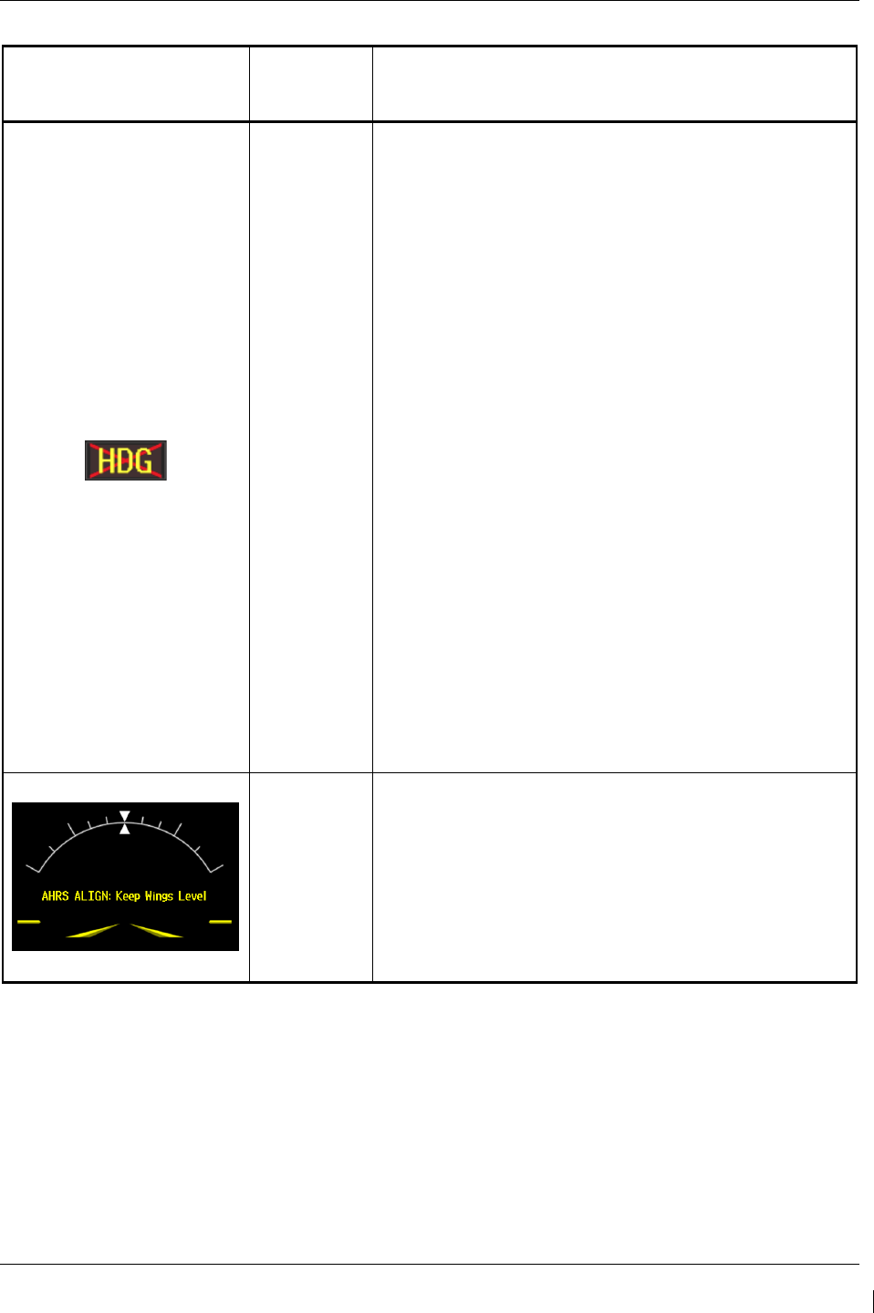
G1000/GFC700 System Maintenance Manual – C90A/C90GT/C90GTi King Air Page 5-23
190-00682-01 Revision G
Invalid Data Field Associated
LRU(s) Solution
HDG FAIL
GRS 77
&
GMU 44
• Ensure metal objects (tool boxes, power carts, etc.)
are not interfering with the magnetometer and aircraft
is not in hangar, near other buildings, parked over
metal drainage culverts or on hard surfaces that may
contain steel reinforcements
• Ensure that a cell phone or a device using cell phone
technology is not turned on (even in a monitoring
state) in the cabin.
• Cycle power after moving aircraft away from metal
objects to determine if metal objects were the source
of the interference. Allow up to five minutes for the
heading to reinitialize.
• Perform a Magnetometer Interference Test to check
for interference from onboard electrical system
components (e.g. NAV lights). Pay particular
attention to any new electrical devices that have
been installed since the aircraft was new. Correct
any discrepancies that do not allow this test to pass
before continuing.
• Ensure GRS 77 and GMU 44 connectors are secure.
• Check the wiring and any inline connectors between
the GRS and GMU for faults.
• Recalibrate the GMU 44,
• Load configuration files to the PFD1, PFD2, GIA1,
and GIA2
If problem persists replace the GMU 44.
If problem persists, replace the GRS 77.
GRS 77
&
GMU 44
• If this message persists longer than five minutes,
perform AHRS calibration procedures as described in
Section 7.7.3.
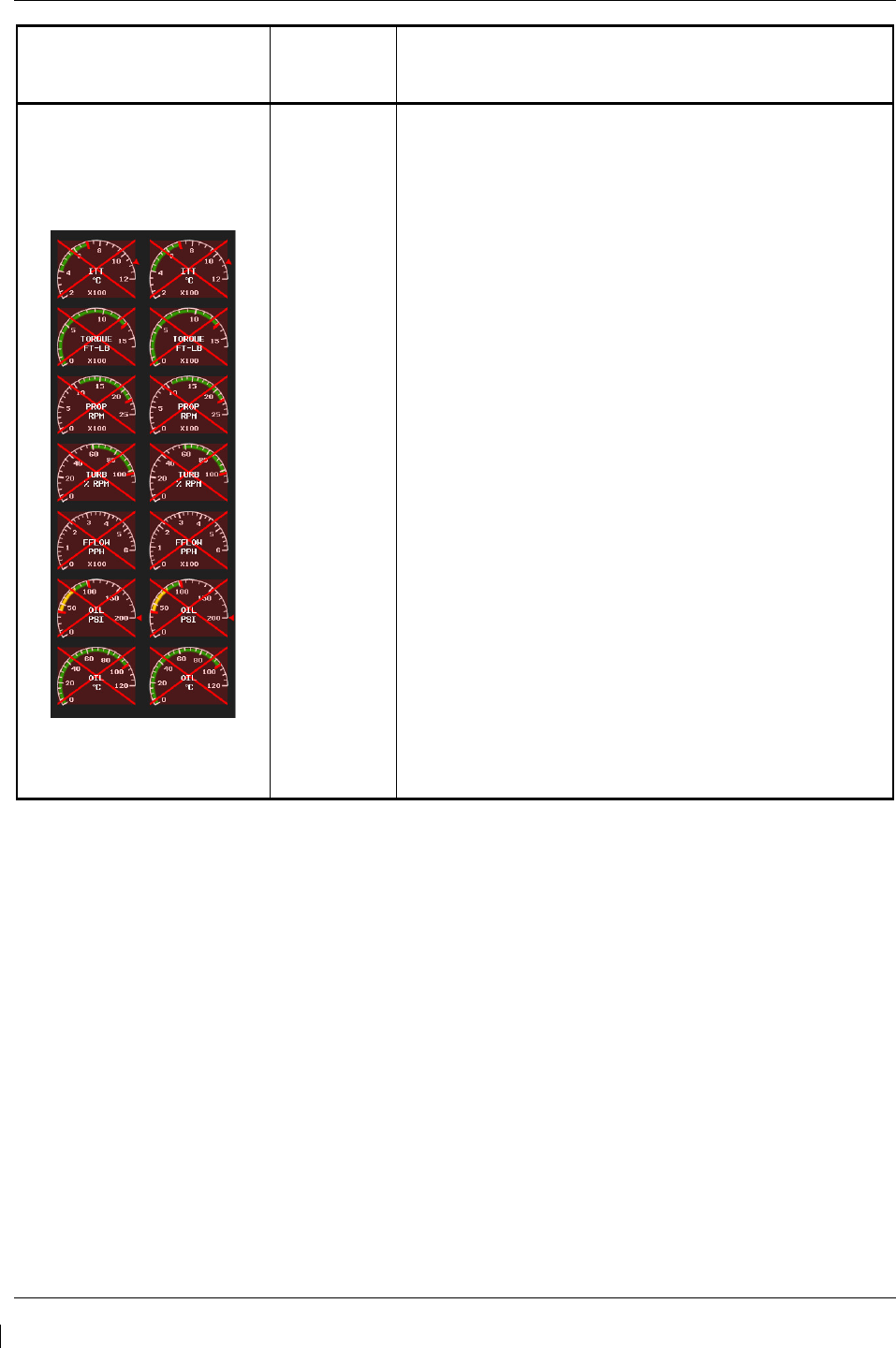
Page 5-24 G1000/GFC700 System Maintenance Manual – C90A/C90GT/C90GTi King Air
Revision G 190-00682-01
Invalid Data Field Associated
LRU(s) Solution
Engine/Airframe Sensors (All
Invalid)
GEA 71
&
GIA 63W
• If software was loaded to a new GDU display, be
sure that the user settings for the replaced display
were cleared. Clear user settings by pressing the
CLR key on the replaced display while applying
power to it. Acknowledge the on-screen prompt by
pressing the ENT key or the right-most softkey.
• Check for GEA related Alert messages on the PFD.
Correct any Alerts concerning software or
configuration errors by reloading software or
configuration as noted.
• Verify GEA internal power supply, configuration, and
calibration status in configuration mode.
The internal power supply, configuration and
calibration boxes should be valid (green
checkmark (√)). If they are invalid (red X),
replace the GEA 71.
• Verify internal, external, and reference voltages listed
in the Main Analog and I/O A Analog boxes are not
dashed out (does not include Aircraft Power 1 and 2).
If any voltages are dashed out, replace the GEA.
• Ensure the GEA is online (green checkmark on the
AUX – SYSTEM STATUS page).
If GEA is not online, verify unit is receiving power
at the rack connector.
Check the GIA/GEA interconnects for faults.
Reload configuration files to both GIA’s and the
GEA.
• If problem persists, replace the GEA 71.
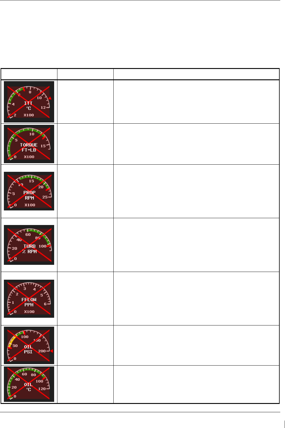
G1000/GFC700 System Maintenance Manual – C90A/C90GT/C90GTi King Air Page 5-25
190-00682-01 Revision G
5.2.3 Engine/Airframe Instrument Failures
The following table provides guidance for troubleshooting individual engine/airframe sensor failures. Be
sure to also follow previous guidance given for the GEA 71. The technician should troubleshoot to
isolate the fault by checking sensor-to-GEA wiring, replacing the suspect sensor, and finally by replacing
the GEA 71. Replace one part at a time. Refer to Section 7.4.1 to check for correct operation of the
sensors and GEA 71 after any part has been replaced. Refer to G1000/GFC 700 Wiring Diagram and
King Air Model 90 Series Maintenance Manual (listed in Table 1-2) as needed.
Invalid Field Sensor Possible Solutions (for applicable engine/system)
ITT
• Check thermocouple cable.
• Replace thermocouple cable.
• Replace GEA 71.
Torque
• Check torque transmitter interface wiring to GEA.
• Check power input to torque transmitter.
• Replace torque transmitter.
• Replace GEA 71.
Prop RPM
• Check prop tachometer - Signal Conditioner wiring.
• Check Signal Conditioner interface wiring to GEA.
• Check power input to Signal Conditioner.
• Replace prop tachometer sensor.
• Replace Signal Conditioner. Refer to Section 6.19.
• Replace GEA 71.
Turbine RPM
• Check engine speed tachometer - Signal Conditioner wiring.
• Check Signal Conditioner interface wiring to GEA .
• Check power input to Signal Conditioner.
• Replace engine speed tachometer sensor.
• Replace Signal Conditioner. Refer to Section 6.19.
• Replace GEA 71.
Fuel Flow
• Check fuel flow transmitter – Signal Conditioner wiring.
• Check Signal Conditioner - GEA wiring.
• Check power input to Signal Conditioner.
• Replace fuel flow transmitter.
• Replace Signal Conditioner. Refer to Section 6.20.
• Replace GEA 71.
Oil Pressure
• Check oil pressure sensor – GEA wiring.
• Replace oil pressure sensor.
• Replace GEA 71.
Oil Temperature
• Check oil temperature sensor – GEA wiring.
• Replace oil temperature sensor.
• Replace GEA 71.
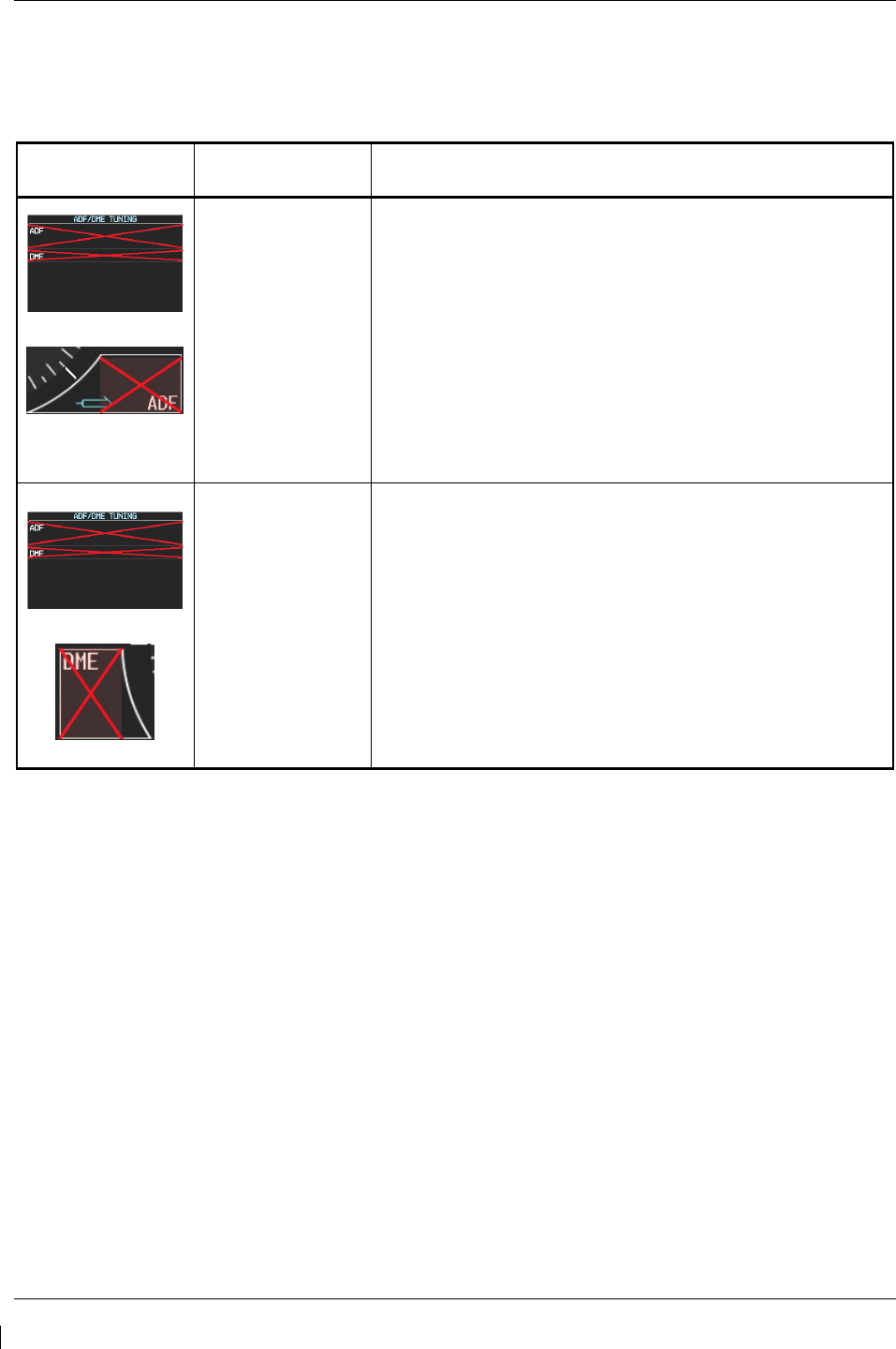
Page 5-26 G1000/GFC700 System Maintenance Manual – C90A/C90GT/C90GTi King Air
Revision G 190-00682-01
5.2.4 ADF/DME Failure
A DME or ADF failure is represented by the following red X’s. Refer to G1000/GFC 700 Wiring
Diagram and King Air Model 90 Series Maintenance Manual (listed in Table 1-2) as needed.
Invalid Field Sensor Solutions
Rockwell Collins
ADF
• Ensure that GIA 63 #2 is properly functioning.
• Reload the ADF option configurations.
• Check for proper operation of the ADF receiver. Ensure
that the receiver is receiving power.
• Check ADF – GIA2 interconnect.
• For other failures of the ADF system, refer to King Air
Model 90 Series Maintenance Manual, listed in Table
1-2.
Rockwell Collins
DME
• Ensure that GIA 63 #1 is properly functioning.
• Reload the DME option configurations.
• Check for proper operation of the DME receiver. Ensure
that the receiver is receiving power.
• Check DME – GIA1 interconnect.
• For other failures of the DME system, refer to the King
Air Model 90 Series Maintenance Manual, listed in Table
1-2.

G1000/GFC700 System Maintenance Manual – C90A/C90GT/C90GTi King Air Page 5-27
190-00682-01 Revision G
5.3 C90A/C90GT/C90GTi Specific Alerts
The following alerts are configured specifically for the C90A/C90GT/C90GTi:
ANNUNCIATION ADVISORY Alerts
Message Advisory Solution
AVN 1 FAN FAIL – Avionics cooling fan #1 is
inoperative.
• Ensure that the PFD/GIA FAN (LEFT and RIGHT) and
MFD FAN circuit breakers are closed.
• Check cooling fan wiring. Refer to G1000/GFC 700
Wiring Diagram, listed in Table 1-2.
•
Replace cooling fan. Refer to Sections 6.26 and 6.27.
AVN 2 FAN FAIL – Avionics cooling fan #2 is
inoperative.
PFD 1 FAN FAIL – PFD #1 cooling fan is
inoperative.
PFD 2 FAN FAIL – PFD #2 cooling fan is
inoperative.
MFD FAN FAIL – MFD cooling fan is inoperative.
ESP FAIL – ESP is inoperative. Troubleshoot the GFC 700 AFCS. Refer to Section 5.6.
ESP OFF – ESP selected off. Check that the MFD AUX-SYSTEM SETUP 2 page shows
“Stability & Protection” status is “ENABLED”.
ESP DEGRADE - ESP IAS mode is inoperative. Ensure ADC1 and ADC2 circuit breakers are closed and units
are providing valid airspeed data.
ESP CONFIG – ESP config error. Config service
req’d.
• Ensure that the “ESP Support Option” has been installed
per Section 3.9.4.12.
• Ensure that the “Enhanced AFCS unlock card” has been
installed per Section 3.9.12.
If the ESP option needs to be removed, reload the baseline
configuration for the specific airframe and all applicable
options as described in Section 3.9. Reloading the baseline
configuration disables all previously enabled options.
NOTE
From this point forward, all message advisory alerts presented are common to all G1000
systems and are not specific to the C90A/C90GT/C90GTi. Messages are grouped
according to LRU.
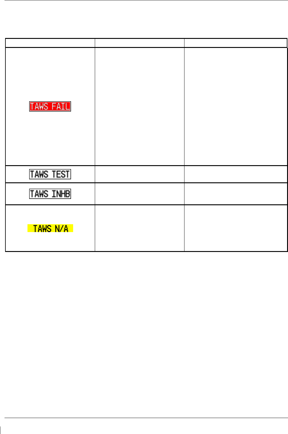
Page 5-28 G1000/GFC700 System Maintenance Manual – C90A/C90GT/C90GTi King Air
Revision G 190-00682-01
5.4 TAWS Troubleshooting
Annunciation Cause Solution
A TAWS system failure has
occurred.
• If message occurred on the first
power up after unlocking TAWS,
cycle power to initialize TAWS.
• Ensure each GDU contains the
correct database data card.
• Ensure the G1000 is configured for
TAWS:
If the system is not configured
for TAWS, reconfigure per
Section 3.9.6.
• Verify GIAs are online.
• Ensure a database or GDU SW
mismatch has not occurred.
If a mismatch has occurred,
load correct database/software
files or replace the terrain card.
TAWS system is currently
being tested.
N/A – Test will be conducted up to two
minutes
TAWS system alerting is
disabled
Enable TAWS system alerting by
pressing the INHIBIT softkey on the
MAP – TAWS page.
GPS system integrity not high
enough to enable TAWS
• Ensure valid GPS position is
received from the AUX – GPS
STATUS page.
• Check GPS antenna & associated
coaxial cabling.
• Troubleshoot GIAs.

G1000/GFC700 System Maintenance Manual – C90A/C90GT/C90GTi King Air Page 5-29
190-00682-01 Revision G
5.5 Synthetic Vision and Pathways Troubleshooting
The SVS/Pathways software feature requires the following G1000 sensors/data to be valid:
• AHRS
• Heading
• GPS Position
• 9 Arc-Second Terrain Data
In the event that one the above items fails or is unavailable, the SVS/Pathways feature is automatically
removed from the PFD. The following table describes possible symptoms associated with the
SVS/Pathways feature, and provides corresponding actions for troubleshooting:
Table 5-1, SVS Troubleshooting
Symptom Recommended Action
“SYN VIS” softkey does not
appear on PFD softkey tier. Follow the steps in Section 3.9.11 to reactivate the SVS/Pathways feature.
3D terrain presentation does not
appear on PFD.
Verify that P/N 010-00330-43 terrain datacards are installed in the lower slot
of the PFDs and MFD.
Verify that the alert messages shown in Table 5-2 are not displayed on the
PFD Alerts Window. If so, follow the solutions described in Table 5-2.
Verify that the G1000 AHRS and heading data are valid on the PFD. Verify
that a valid GPS 3D position solution is being received. Troubleshoot these
systems in accordance with sections 5.10.4 and 5.14.
If a terrain database update has just been performed, allow the system time
to initialize and verify the data. When the databases have been verified, the
current database cycle and version are reported on the MFD AUX – System
Status page.
The following table provides SVS/Pathways specific alert messages which may appear in the Alerts
Window on the PFD (press the ALERTS softkey on the PFD to view the Alerts Window):
Table 5-2, SVS-Related Alert Messages
Failure Message Cause Solution
SVS – SVS DISABLED: Out of
available terrain region.
SVS is disabled because the
aircraft exceeded the boundaries
of the loaded terrain database.
Geographical operation limitations are
defined in the AFMS listed in Table 1-2.
Ensure that operations are within this
geographic area.
SVS – SVS DISABLED: Terrain
DB resolution too low
SVS is disabled because a 9 Arc-
Second or better database is not
currently loaded.
Ensure the P/N 010-00330-43 Terrain
Cards are installed in the lower slot of
each display.
If terrain data has been recently
updated, ensure that the correct 9 Arc-
Second databases were used.
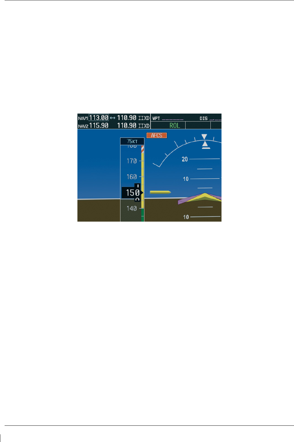
Page 5-30 G1000/GFC700 System Maintenance Manual – C90A/C90GT/C90GTi King Air
Revision G 190-00682-01
5.6 GFC 700 AFCS Troubleshooting
The GFC 700 is a digital Automatic Flight Control System (AFCS) which is integrated into various
components of the G1000. This section touches upon key items to note while troubleshooting the GFC
700.
Should a problem be encountered during the operation of the GFC 700, the pilot and technician should
first evaluate the overall status and condition of the G1000 system at the AUX – System Status page (on
MFD). Any alert messages, annunciations, or other abnormal behaviors should be noted in an effort to
pinpoint the fault. The object is to locate the fault within a LRU or LRUs in efforts to replace the
defective equipment.
The GFC 700 AFCS Annunciation field is located above the airspeed tape on the PFD as shown:
Figure 5-5, AFCS Annunciation Field
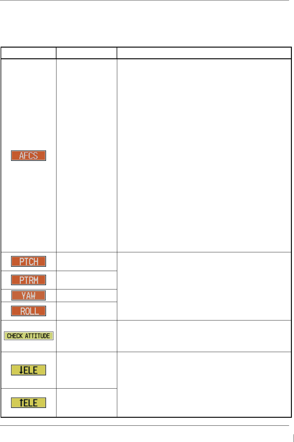
G1000/GFC700 System Maintenance Manual – C90A/C90GT/C90GTi King Air Page 5-31
190-00682-01 Revision G
5.6.1 General Troubleshooting
The following annunciations may appear in the AFCS Annunciation field:
Table 5-3. AFCS Annunciation Troubleshooting
Annunciation
Condition Resolution
AFCS System
Failure
• Confirm AFCS Servo circuit breaker IN
• Ensure that the G1000 system is in proper working order.
Check specifically for proper operation of the:
GIA 63 Integrated Avionics Units
GRS 77 AHRS Units
GDC 74B Air Data Computers
All GSA 80 and GSA 81 Servos
• Check that no red X’s are present on the MFD and PFD
displays.
• Check that no related alert messages are present on the
PFD displays (press the ALERTS softkey).
• Go to the AUX SYSTEM STATUS page on the MFD and
verify that all LRUs have a ‘green’ check (see Section 5).
• In Configuration mode, review the GFC 700 equipment
status, software, and certification gains.
• Reload software, configuration, and certification gains to the
GIAs and GSA 80 and GSA 81 servos.
• Check the GFC Status page for additional GFC 700 system
information.
• Review the fault and assert logs for the GIAs and servos
(see Section 5.6.4)
• Isolate the fault to an LRU. Replace this LRU and confirm
the resolution of the annunciation.
Pitch Axis Failure
• Check the AUX – SYSTEM STATUS page to see if the
servo is online (green check).
• Check that the affected servo is receiving power.
• Check the servo wiring and connector.
• For pitch trim, check pitch trim switch operation to verify
switch contacts are not stuck.
• If failure condition still exists, remove and replace the
affected servo.
Pitch Trim Axis
Failure
Yaw Axis Failure
Roll Axis Failure
AHRS Monitor
Failure
• If the AHRS inputs have been determined to be
“unreasonable” while the AP is engaged, in air, this message
will be displayed until AHRS inputs are determined
reasonable for 5 seconds.
Elevator Mis-Trim
Down
• If elevator mistrim annunciations persist, check the pitch and
pitch trim servos for proper operation. Verify that the servo
is online at the AUX – SYSTEM STATUS page.
• Check the servo wiring and connectors. Ensure the servo is
receiving power.
• Check the aircraft control adjustments.
• If mistrim condition still exists, remove and replace the
affected servo.
Elevator Mis-Trim
Up
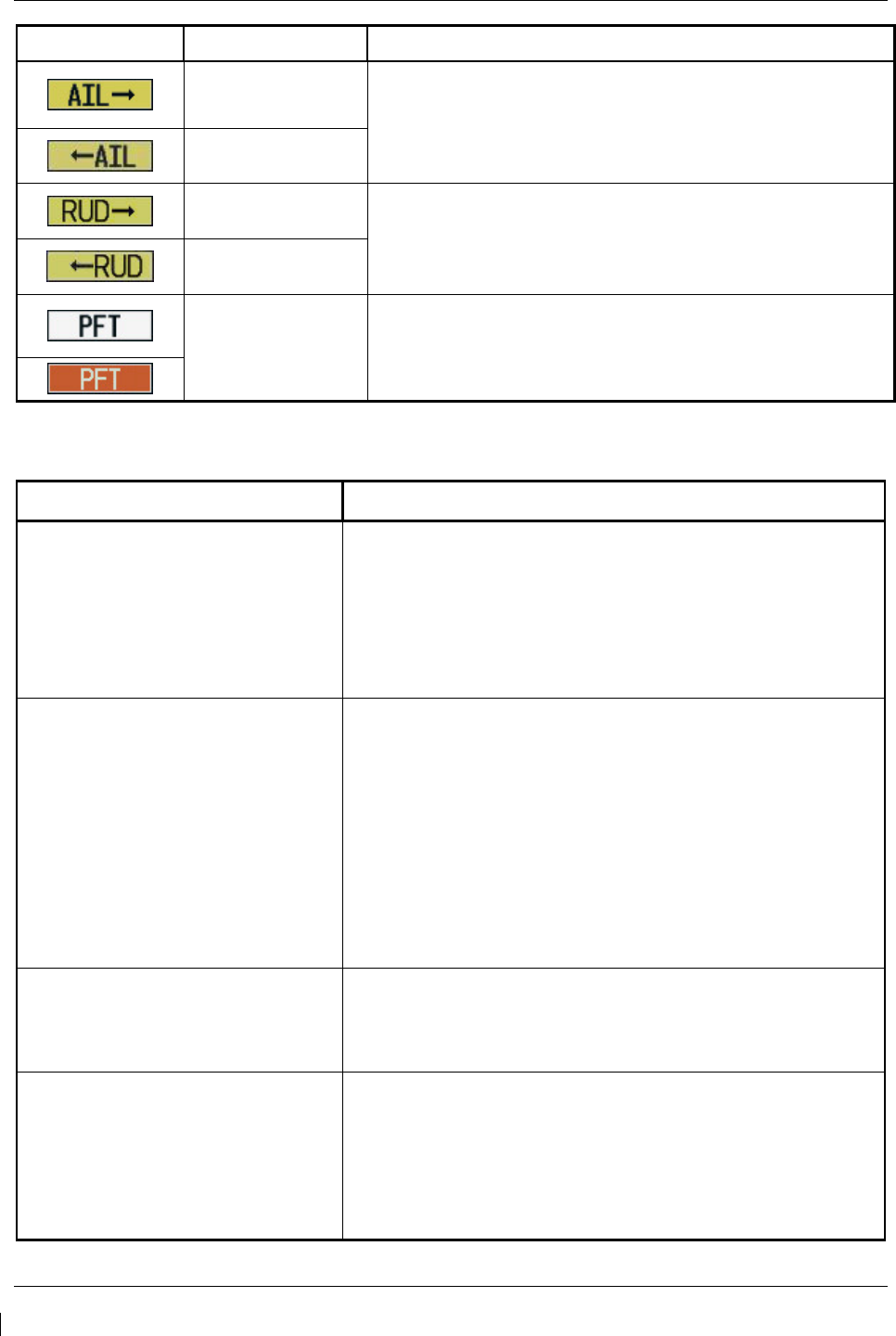
Page 5-32 G1000/GFC700 System Maintenance Manual – C90A/C90GT/C90GTi King Air
Revision G 190-00682-01
Annunciation
Condition Resolution
Aileron Mistrim
Right
• Check for possible fuel imbalance.
• Check aileron control adjustments.
• If mistrim condition still exists remove and replace the roll
servo.
Aileron Mistrim
Left
Rudder Mistrim
Right
• Check rudder control adjustments.
• If mistrim condition still exists remove and replace the yaw
servo.
Rudder Mistrim
Left
Pre-Flight Test
Fails
• Allow the system to complete pre-flight tests.
• The preflight test should finish within 2 minutes. If it does
not pass, the red ‘PFT’ annunciation is shown. In case of
PFT failure, see Section 5.6.5
for additional PFT diagnostics.
Table 5-4. AFCS General Troubleshooting
Condition Resolution
Poor AP Performance
(Limited AP Authority)
• Check each servo mount slip clutch per Section 4.9. Verify
the clutches are not excessively loose and are within
torque limits.
• Check aircraft controls for proper adjustment per the King
Air Model 90 Series Maintenance Manual.
• Check aircraft control cables for proper tension per the
King Air Model 90 Series Maintenance Manual.
AP DISC Problems
• For intermittent nuisance disconnects with no AFCS of PFT
alert, check A/P disconnect switch and wiring for
intermittent faults.
• If an AFCS or PFT alert is displayed at the time of the
disconnect, troubleshoot per Section 5.5.
• Check the GIA AFCS Fault Logs according to Section
5.6.4. If a Mon Prmtr Invalid message is received, check
for valid true airspeed. A faulty GTP 59 OAT probe may
cause TAS to become invalid, which will flag the
Mon Prmtr Invalid message.
• Contact Garmin Product Support for assistance
Loss of Manual Electric Trim
• Check pitch trim servo status.
• Check MET switch discrete inputs to both GIAs by going to
the GIA I/O Configuration page and selecting DISCRETE
IN inputs.
AutoTrim Inoperative
• Check flap-in-motion discrete inputs to both GIAs for proper
operation by going to the GIA I/O Configuration page and
selected DISCRETE IN inputs. See Section 4.8.
• If DATA indicator fails to illuminate or illuminates
incorrectly, troubleshoot flap motor & discrete input wiring
(refer to G1000/GFC 700 Wiring Diagram, listed in Table
1-2).
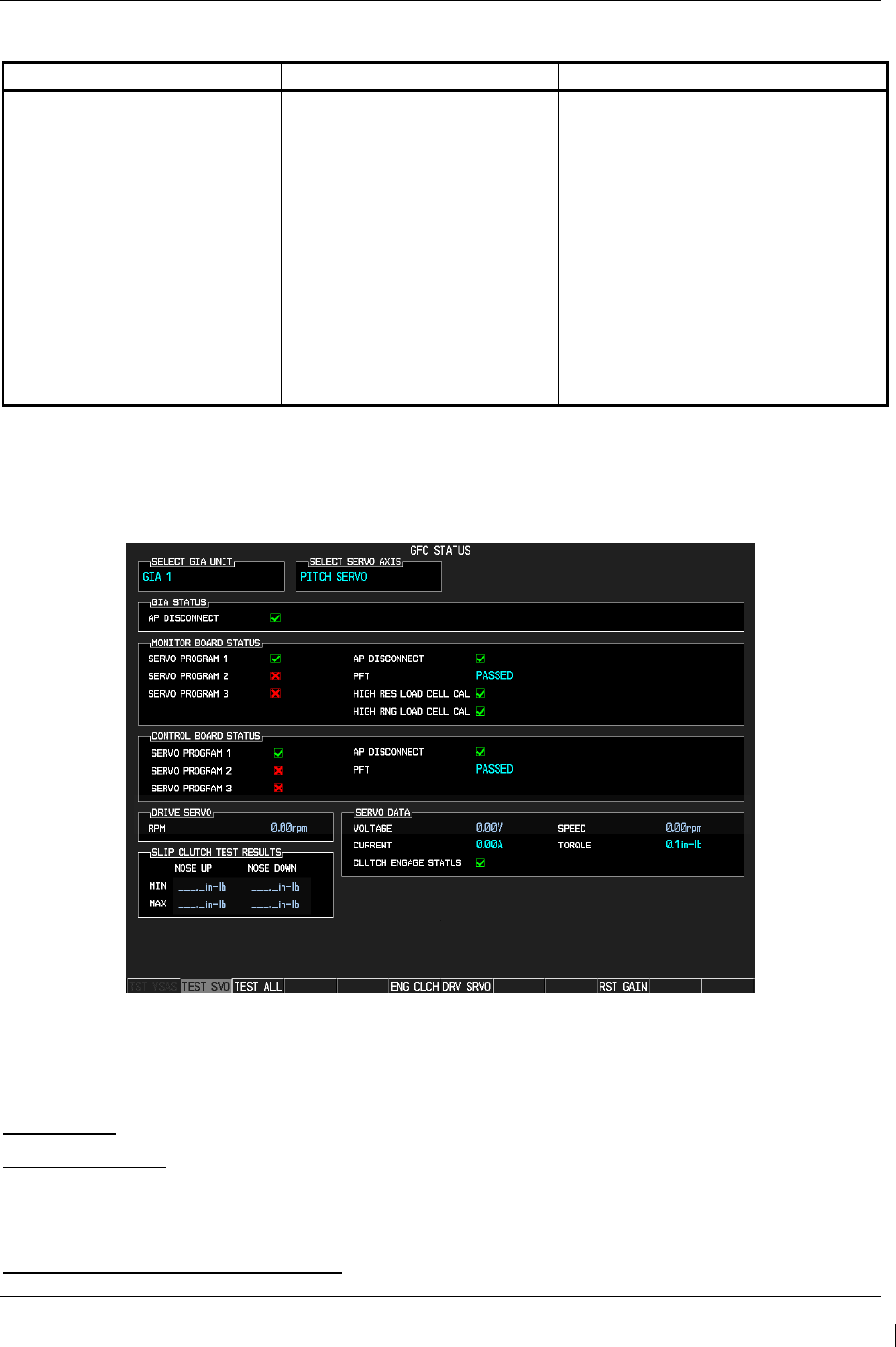
G1000/GFC700 System Maintenance Manual – C90A/C90GT/C90GTi King Air Page 5-33
190-00682-01 Revision G
5.6.2 GFC Configuration Alerts (SW Version 0636.03 and Subs)
Failure Message Cause Solution
MANIFEST – GFC software
mismatch. Communication
Halted.
The system has detected an
incorrect software version loaded
in the GSA 8X servos, or the
system has not been able to
detect a serial number from the
GSA 8X servo(s).
NOTE: The software version
loaded to the servo is determined
by the serial number of the GSA
8X unit. When the serial number
is not reported by either the
monitor or motor-control circuit
board, this failure message will be
present.
• Load the correct software. See
Section 3.9 for the Software Loading
procedure.
• If a GSA 8X servo is not showing on
the SYSTEM UPLOAD page after
loading completes, check the
monitor board entry (ex: GSA ROLL
MON, GSA PTCH TRM M) and
motor-control board entry (ex: GSA
ROLL CTL, GSA PTCH TRM C) on
the SYSTEM STATUS page. If the
unit is not reporting serial number for
either or both boards, replace the
servo.
5.6.3 GFC Status Page
The GFC Status page is presented in configuration mode and gives status information regarding the
GFC 700.
Figure 5-6. GFC Status Page
NOTE
Reference Table 3-1 for interpretation of data indicator symbols
GIA STATUS
AP DISCONNECT: Shows the condition of the AP DISC +28 VDC input to the GIAs and servos, which
is required for the Autopilot to operate. A valid data indicator shows the AP DISC switch is closed and
the GFC 700 is activly receiving 28. volts. An invalid indicator box indicates the GIAs and servos are no
longer receiving the +28 VDC AP DISC power (switch open or other fault).
MONITOR/CONTROL BOARD STATUS

Page 5-34 G1000/GFC700 System Maintenance Manual – C90A/C90GT/C90GTi King Air
Revision G 190-00682-01
Shows the condition of various monitor board components.
SERVO PROGRAM (1-3): Servo program discretes are used to determine the HW strapping for each
GSA to define the servo type. This information can be cross-referenced against the system interconnects
to verify proper servo grounding.
AP DISCONNECT: Same as GIA Status.
PFT: Indicates whether the pre-flight test has passed or failed.
HIGH RES & HIGH RNG LOAD CELL CAL: Shows the condition of the high resolution and high range
load cells on the monitor board. An invalid data indicator box indicates a corrupt or missing load cell
calibration; return the servo to Garmin.
DRIVE SERVO
Allows the technician to enter a desired RPM at which to manually drive the selected servo. Direction of
rotation is controlled by the polarity of the RPM (+ or -). After the speed is entered, the technician may
use the ENG CLCH and DRV SRVO softkeys to drive the servo.
NOTE
Be especially certain that the flight controls are clear and safe to operate before manually driving the
servo.
SERVO DATA
Shows real-time reported data including servo voltage, speed, motor current, load cell torque, and clutch
solenoid status. A valid data indicator box indicates the servo clutch is engaged.
SLIP CLUTCH TEST RESULTS
This window is used during the automatic slip clutch torque measurement check.
5.6.4 GIA Fault Log Descriptions
The section was created to help determine why the GFC 700 has failed the Pre-Flight Test indicated by
the red PFT annunciation , it defines the PFT sequence for the servos and the GFC 700
system and then provides troubleshooting information to help resolve failures.
There are 16 steps to the GFC 700 PFT. The PFT is performed by both GIA’s at startup, and needs to
pass on both GIA’s before the autopilot can be engaged.
The PFT is only started if the AHRS has aligned, the GIA’s and servos are configured and the
certification gains are valid. If the PFT has not completed after one minute from when the initialization
started, the PFT will fail. After the system PFT has passed, it will be performed again if a servo resets, if
the autopilot servo breaker is reset or the cross side GIA restarts it.
Generally, the PFT failure fault is logged in the GIA Maintenance Log and not in the Servo Maintenance
Logs unless the GIA log fault identifies a servo problem.
NOTE
Thoroughly understanding the operation of the G1000 system in Configuration mode is
recommended before starting this procedure. The GFC Status page may be used to check
the status of the servos and engage them to aid in troubleshooting
To access the GIA and GSA Maintenance Logs, perform the following steps –

G1000/GFC700 System Maintenance Manual – C90A/C90GT/C90GTi King Air Page 5-35
190-00682-01 Revision G
1. Start the G1000 in Configuration mode.
2. Use the FMS knob on PFD1 to go to the Diagnostics Terminal page in the System group. This
page allows the technician to view maintenance logs associated with the GFC 700.
3. Choose ‘GIA 1’ or ‘GIA 2’ in the LRU window.
4. In the SERVO window, choose ‘NONE’ to view the GIA Maintenance Log, or choose a servo to
view their logs.
5. Using the FMS knob, choose ‘VIEW MAINTENANCE LOG’ in the COMMAND window.
6. Press the ENT key.
7. When the Maintenance Log data starts to display in the OUTPUT window, you may see
"More...press any key to continue..." at the bottom of the OUTPUT window. This informs you
there is more data to display and the system has paused allowing you to view the data before
continuing. To see more of the data, reselect the "VIEW MAINTENANCE LOG" in the
COMMAND window and press the ENT key. The "...press any key to continue..." function is not
active at this time.
8. Scroll through the OUTPUT list by pressing the OUTPUT softkey.
The GIA Maintenance Log can record any of the following faults:
• FCS Task not started: Bad gains
The FCS task has not started because the gains are not present or have been corrupted.
Reload the gain files to correct.
• FCS Task not started: Gain structure out of range
The FCS task has not started because the gains are not compatible with the GIA software.
Reload the gain files to correct.
• PFT FAIL: Timeout, <STEP>
Pre-flight test has failed because the specified step has not passed in the allotted time. See the GIA
pre-flight steps for a description of the possible values for <STEP> on the failed GIA and corrective
actions.
• PFT FAIL: Cross GIA Failed, State: <STEP>
Pre-flight test has failed on opposite GIA. <STEP> specifies the pre-flight test step on selected GIA
that was in progress when the pre-flight test failed on the opposite GIA. See the GIA pre-flight steps
for a description of the possible values for <STEP> on the failed GIA and corrective actions.
• PFT FAIL: <STEP>
Pre-flight has failed because the step specified has failed. See the GIA pre-flight test steps for a
description of the possible values for <STEP> on the failed GIA and corrective actions.
• AHRS MON invalid: <STATE>
The AHRS monitor has detected that the AHRS data is invalid. The possible values for <STATE>
are:
a. Mon Prmtr Invalid: The ARINC 429 data used by one of the monitors has not been
received.
b. Attitude Prmtr Invalid: The ARINC 429 pitch or roll angle has not been received.
c. Exceeded Attitude Limits: The pitch or roll angle has exceeded the engagement limits.

Page 5-36 G1000/GFC700 System Maintenance Manual – C90A/C90GT/C90GTi King Air
Revision G 190-00682-01
d. Cross Hdg Accel Fail: Cross heading acceleration monitor failed.
e. Vert Accel Fail: Vertical acceleration monitor failed.
f. Fltrd Cross Hdg Accel Fail: Filtered cross heading acceleration monitor failed.
g. Fltrd Vert Accel Fail: Filtered vertical acceleration monitor failed.
h. Roll Accel Fail: Roll acceleration monitor has failed.
i. Normal Accel Fail: Normal acceleration has failed.
Troubleshoot the GRS 77 for the cause of the failure.
• Stuck switch invalidated parameter: <AXIS>
An MET switch in the specified axis is stuck.
Check the MET (trim) switches for proper operation.
• PRMTR: <PARAMETER> MODE:<MODE> Parameter lost
The mode specified by <MODE> has been disengaged because the parameter specified by
<PARAMETER> has become invalid. The following is a list of some of the possible values for
<PARAMETER>:
a. AD TDM Comm Valid: The specified mode has been disengaged because communication
with the servos, via the Time Division Multiplexer protocol, has been lost.
b. AP Pitch MET not stuck: The specified mode has been disengaged due to a stuck pitch
MET switch.
Check the MET (trim) switches for proper identification.
5.6.5 GIA Pre-Flight Test Steps
PFT Step 0: System initialization, verify GFC powered
This step is checking to make sure the GFC is powered up. It checks to make sure the GIA AP
disconnect input is connected to 28 volts, and makes sure the Servos are up and communicating.
If this step fails, make sure the GIA is connected to AP disconnect by using the GFC configuration
page. Also make sure all configured Servos are communicating by checking for Servo product data
in configuration mode.
PFT Step 1: System initialization, verify GIA audio is valid.
This step is checking to make sure that the GIA audio region has been loaded and configured.
If this step fails, load GIA audio region and audio configuration.
PFT Step 2: System initialization, verify required servos are configured
This step is checking to make sure the current Servo configuration matches the Servo configuration
specified in the certification gain file.
If this step fails, then make sure the Servo configuration on the GFC configuration page matches the
Servo configuration specified in the configuration gain (.cgn) file.

G1000/GFC700 System Maintenance Manual – C90A/C90GT/C90GTi King Air Page 5-37
190-00682-01 Revision G
PFT Step 3: System initialization, verify selected side
This step is checking to make sure the PFD1 is online and sending the selected AFCS side data over
HSDB to GIA1.
If this step fails, then make sure the PFD is powered up and there is an Ethernet connection from the
PFD to the GIA.
PFT Step 4: System initialization, verify AHRS monitor
This step is checking to make sure the AHRS monitor is valid and not reporting an AHRS failure.
NOTE: AHRS monitor will be assumed valid if on the ground.
If this step fails, then make sure the AHRS and ADC is powered up and sending valid attitude data to
the G1000.
PFT Step 5: System initialization, verify servo PFT is complete
This step is checking to make sure that all servos have completed their own PFT. This does not check
whether the servo PFT passed or failed. It verifies that the servo PFT is no longer in progress.
PFT Step 6: Verify cross GIA is initialized
This step is checking to make sure the other GIA is also on step 6 of its PFT.
If this step fails, try cycling power on GIA1, GIA2, and all servos. If PFT still fails at step 6 then you
will need to go check the PFT status of the other GIA and see what step it is failing (it should be prior
to step 6). NOTE: The PFT status is communicated between GIA1 and GIA2 using HSDB. As a
result, both the PFD and MFD must be powered for this state to pass.
PFT Step 7: Verify servo type
This step is checking to make sure the Servos are the correct type (torque and speed).
If this step fails, make sure the Servo configuration on the GFC configuration page matches the
Servos installed in the aircraft.
PFT Step 8: Verify servo first certification data
This step is checking to make sure the servos have the same certification gains loaded in them as the
GIAs have.
If this step fails, reload the certification gains in GIA1, GIA2, and all servos.
PFT Step 9: Verify servo second certification data
This step is checking to make sure the servos have the same certification gains loaded in them as the
GIAs have.
If this step fails, reload the certification gains in GIA1, GIA2, and all servos.
PFT Step 10: Updating servo RTC
This step is setting the system time in the servos to the same time as the GIA system time.
This step should never fail.

Page 5-38 G1000/GFC700 System Maintenance Manual – C90A/C90GT/C90GTi King Air
Revision G 190-00682-01
PFT Step 11: Verify servo PFT status
This step is checking to make sure the servos have all passed their own PFT.
If this step fails, please proceed to servo PFT explanation below.

G1000/GFC700 System Maintenance Manual – C90A/C90GT/C90GTi King Air Page 5-39
190-00682-01 Revision G
PFT Step 12: Verify AP disconnect enabled
This step is checking to make sure GIA1, GIA2, and all servos have are connected to a 28 volt AP
disconnect.
If this step fails, make sure the AP disconnect input to GIA1, GIA2, and all servos is connected and
registering 28 volts. Make sure the AP disconnect switch has been installed in the aircraft. Make
sure no one is holding the AP disconnect switch down on the yoke.
PFT Step 13: Verify servo validity
This step is checking to make sure all the Servos are up and communicating with valid data to the
GIA in TDM mode.
If this step fails, then make sure all Servos are turned on and communicating by checking for green
boxes on the GFC configuration page.
PFT Step 14: Verify cross GIA PFT is completed
This step is checking to make sure the other GIA is also on step 14 of its PFT.
If this step fails, try cycling power on GIA1, GIA2, and all servos. If PFT still fails at step 14 then
you will need to go check the PFT status of the other GIA and see what step it is failing. NOTE: The
PFT status is communicated between GIA1 and GIA2 using HSDB. As a result, both the PFD and
MFD must be powered for this state to pass.
PFT Step 15: PFT completed
The PFT has successfully completed.
PFT Step 16: PFT failed
The PFT has failed.

Page 5-40 G1000/GFC700 System Maintenance Manual – C90A/C90GT/C90GTi King Air
Revision G 190-00682-01
5.6.5.1 Servo Faults and Troubleshooting
Whenever a servo fault occurs, a status message is logged to the corresponding servo control or monitor
maintenance log. This information is also accompanied by a time and date stamp. An “RTC DATE”
entry is made every time a servo is powered on, it is normally not useful for troubleshooting.
The following is a listing of possible faults that could be reported in a GSA fault log. Faults can occur in
either the monitor board processor or the control board processor, both of which are contained in the GSA
unit.
Monitor Processor
The monitor processor contains the logs that are found in these processors -
2 – Pitch Servo
4 – Roll Servo
6 - Yaw
8 – Pitch Trim Servo
There are two main groupings of faults that can occur in the monitor processor:
The first grouping of faults can occur during the GSA unit pre-flight test (PFT). If there is a
fault during PFT the unit will not be able to transition to normal mode and the only way to clear
this state would be to cycle unit power.
The second grouping of faults can occur during normal mode. These faults generally cause a
disconnect of power to the GSA and report to the GIA that a fault has occurred.
The Notes column indicates any actions that can be taken to troubleshoot the problem in the
aircraft by the technician. Any faults that are not listed here indicate an internal problem
requiring replacement of the servo. If the items in the Notes column check out ok, replace the
servo.
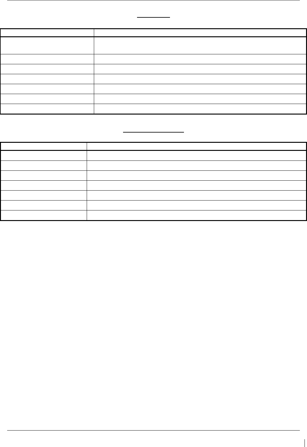
G1000/GFC700 System Maintenance Manual – C90A/C90GT/C90GTi King Air Page 5-41
190-00682-01 Revision G
PFT Faults
MONITOR PFT STEP
NOTES
"INTERNAL COMM FAIL" This can sometimes be a result of a failure on the other internal servo
board, check faults on the other processor
"UNSW POWER INV" Check unit power
"MON SOL PWR ON FAIL" Check unit power and AP Disconnect power
"CTL SOL PWR ON FAIL" Check unit power and AP Disconnect power
"SOL PWR FAIL" Check unit power and AP Disconnect power
"CERT DATA UNINSTALLED" Upload the certification gain file to the Monitor board
"STRAP CODE MISMATCH" Check the connector strap inputs to the unit
Normal Mode Faults
MONITOR FAULT
NOTES
"GIA DIS FAULT" Check the AP Disconnect power into the unit
"HOST DATA DIF" Check the AHRS wiring to the system
"HOST DATA INV" Check the AHRS wiring to the system
"SVO PWR INV" Check unit power and AP Disconnect power
“STRP CODE CHNG” Check the connector strap inputs to the unit
“MET STUCK SWTCH” Check the MET switch inputs into the system
“MET STATUS DIF” Check the MET switch inputs into the system

Page 5-42 G1000/GFC700 System Maintenance Manual – C90A/C90GT/C90GTi King Air
Revision G 190-00682-01
Control Processor
The control processor contains the logs that are found in these processors –
3 – Pitch Servo
5 – Roll Servo
7 - Yaw
9 – Pitch Trim Servo
There are two main groupings of faults that can occur in the control processor.
The first grouping of faults can occur during the GSA unit pre-flight test (PFT). If there is a fault
during PFT the unit will not be able to transition to normal mode and the only way to clear this
state would be to cycle unit power.
The second grouping of faults can occur during normal mode. These faults generally cause a
disconnect of power to the GSA and report to the GIA that a fault has occurred.
The Notes column indicates any actions that can be taken to troubleshoot the problem in the
aircraft by the technician. Any faults that are not listed here indicate an internal problem
requiring replacement of the servo. If the items in the Notes column check out ok, replace the
servo.
PFT Faults
CONTROL PFT STEP NOTES
"INT COMM TEST FAIL" This can sometimes be a result of a failure on the other board, check
faults on other processor
"CTL MOT PWR ON FAIL" Check unit power and AP Disconnect power
"MON MOT PWR ON FAIL" Check unit power and AP Disconnect power
"HALL 1 FAIL" Check unit power and AP Disconnect power
"HALL 2 FAIL" Check unit power and AP Disconnect power
"HALL 3 FAIL" Check unit power and AP Disconnect power
"HALL 4 FAIL" Check unit power and AP Disconnect power
"HALL 5 FAIL" Check unit power and AP Disconnect power
"HALL 6 FAIL" Check unit power and AP Disconnect power
"CURR OFFST FAIL" Check unit power and AP Disconnect power
"SVO TYPE FAIL" Check unit power and AP Disconnect power
"CERT DATA UNINSTALLED" Upload the certification gain file to the Control board
"STRAP CODE MISMATCH" Check the connector strap inputs to the unit

G1000/GFC700 System Maintenance Manual – C90A/C90GT/C90GTi King Air Page 5-43
190-00682-01 Revision G
Normal Mode Faults
CONTROL FAULT
NOTES
"GIA DIS FAULT" Check the AP Disconnect power into the unit
"HOST DATA DIF" Check the AHRS wiring to the system
"HOST DATA INV" Check the AHRS wiring to the system
"SVO PWR INV" Check unit power and AP Disconnect power
“STRP CODE CHNG” Check the connector strap inputs to the unit
“MET STUCK SWTCH” Check the MET switch inputs into the system
“MET STATUS DIF” Check the MET switch inputs into the system

Page 5-44 G1000/GFC700 System Maintenance Manual – C90A/C90GT/C90GTi King Air
Revision G 190-00682-01
5.6.5.2 Downloading GIA and GSA Maintenance Logs
I
f additional assistance is needed troubleshooting autopilot faults, the Maintenance logs can be
downloaded to an SD card as a text file (.txt) and emailed to Garmin Aviation Product Support.
Please call Garmin Aviation Product Support before you send a Maintenance Log to notify them
you are sending it to prevent a delay in response. You may download multiple GIA and GSA
Maintenance Logs to the same file, however in your email to Garmin you must furnish the order
in which they were downloaded (i.e. GIA1, then GIA2, then SRVO PTCH MON, then SRVO
PTCH CTL, etc.).
1. Insert a FAT 32 formatted SD card into the top slot of the PFD before turning on the displays.
2. Power up PFD1/2 and MFD in the configuration mode.
3. On the PFD1 in the System page group, use the small FMS knob to scroll to the Diagnostics
Terminal page.
4. Press the LG2CRD softkey at the bottom of the PFD1. Verify that the softkey text grays out.
This indicates the recording function is active and all text that is displayed in the OUTPUT
window will be saved to the card.
5. Enable the curser by pressing the FMS knob, select “GIA1” in the LRU drop down menu and
then press the ENT key to select it.
6. Skip the SERVO box and move the cursor to the COMMAND box and select “View
Maintenance Log” in the drop down menu then press the ENT key. The error log data will be
displayed in the OUTPUT box. If you see the “more…press any key to continue” text at the
bottom of the screen, you may need to reselect “View Maintenance Log” for GIA data to allow it
to continue scrolling down the screen (pressing any key will not continue, disregard the text
instruction you to do so). Continue to scroll through all the OUTPUT data until you see the text,
“End of Fault Log”.
7. Move the cursor back to the LRU box, select “GIA2” in the LRU drop down menu and then press
the ENT key to select it.
8. Skip the SERVO box and move the cursor to the COMMAND box and select “View
Maintenance Log” in the drop down menu then press the ENT key. The error log data will be
displayed in the OUTPUT box. If you see the “more…press any key to continue” text at the
bottom of the screen, you may need to reselect “View Maintenance Log” for GIA data to allow it
to continue scrolling down the screen (pressing any key will not continue, disregard the text
instruction you to do so). Continue to scroll through all the OUTPUT data until you see the text,
“End of Fault Log”.
9. If you need to download Servo fault logs (usually done at the request of Garmin Product
Support), perform the following steps. Otherwise, skip to step 10.
a. In the LRU box, you may select either “GIA1” or “GIA2”.
b. In the SERVO box, choose a servo using the FMS knobs. Each servo contains two logs,
one in the Monitor (MON) processor and one in the Control (CTL) processor. You must
download both for each servo separately.
c. In the COMMAND box, select “View Maintenance Log” and press the ENT key.
d. The log will appear in the OUTPUT box. It will scroll to the end automatically. When it
is complete, repeat steps a-c for the other servos in the aircraft. Be sure to note the order
the servos were downloaded in including the Monitor or Control logs to email to Garmin
Product Support. Without knowing the order in which the logs were downloaded,
Garmin will be unable to process them and will ask for another full download.
10. Press the LG2CRD softkey to turn off the recording function.
11. Wait 1 minute for the system to save the data from the download to the SD card.

G1000/GFC700 System Maintenance Manual – C90A/C90GT/C90GTi King Air Page 5-45
190-00682-01 Revision G
12. While you are waiting for the data to be saved to the SD card, record the order of the LRU’s
and/or Servos were downloaded so that you can provide that information to Cessna or Garmin to
help decipher the order of the error data.
13. Power down the G1000 System and remove the SD card.
14. Insert the SD card in the card reader of a laptop or desktop computer and open the
“diag_buf_log.txt” file from the SD card using the WordPad program. Verify that all of the fault
logs were downloaded by checking for the “End of Fault Log” message at the end of the GIA
data, and that the last servo log entry has the current date.
15. Insert the fault log as an attachment to an email and include the LRU order how the data was
downloaded and send to Garmin Aviation Product Support at avionics@Garmin.com.

Page 5-46 G1000/GFC700 System Maintenance Manual – C90A/C90GT/C90GTi King Air
Revision G 190-00682-01
5.7 Backup Communications Path Checks
5.7.1 Overview
The G1000 system architecture is designed with redundant communication ports for several LRUs so that
critical information can continue to be displayed in the event of an equipment or wiring failure. Of most
importance is flight attitude, heading, and air data information. The GRS 77 and GDC 74B each have
four separate ARINC 429 data lines that are all capable of sending data to the displays. The GEA 71,
GTX 33, and GMA 1347D each have two redundant serial communication paths for the same purpose.
See Figure 2-4 for a basic G1000 block diagram depicting this architecture. Several other diagrams are
shown later in this section for illustrative purposes. When troubleshooting, refer to the G1000/GFC 700
Wiring Diagram listed in Table 1-2.
NOTE:
Refer to Section 8.1.6 for procedures on checking the status of each configured G1000 /
GFC 700 backup data path.
5.7.2 Data Path Failures
Failure Message Cause Solutions
FAILED PATH – A data path has
failed.
A communications data path
status is not being received by the
G1000.
Determine which data path has failed:
See Section 8.1.6.
Check wiring continuity for the failed
path.
Swap or replace the affected LRU.

G1000/GFC700 System Maintenance Manual – C90A/C90GT/C90GTi King Air Page 5-47
190-00682-01 Revision G
5.8 GDU 104X Troubleshooting
5.8.1 GDU 104X Common Problems
Symptom Recommended Action
Display is blank
• Ensure that a cell phone or a device using cell phone technology is not
turned on (even in a monitoring state) in the cabin.
• Cycle power.
If GDU recovers, observe display for yellow text containing error
information at the top of the screen. If message indicates software
need to be re-loaded, then re-load software. Otherwise, replace
the GDU.
• Use a bright light to verify LCD is active.
Adjust avionics dimmer control full clockwise.
Manually turn up backlight on the PFD and load configuration files
to the GDU.
• Ensure slide lock is fully engaged with the locking tabs on the back of
the unit.
If slide lock is not fully engaged, remove connector and verify the
locking tabs on the GDU are perpendicular to the connector. If
necessary, straighten them before reseating connector.
• Ensure GDU is receiving power. If a circuit breaker is tripped,
determine source of short before resetting breaker.
• Ensure circuit breakers have not failed and power wire connections are
secure.
• Swap PFD1 and PFD2.
If problem follows unit, replace the display. Please note the
position it failed in (PFD1/2).
If problem does not follow unit, troubleshoot aircraft wiring for fault
.
Display resets
Display flickers
SD card is stuck in GDU
• DO NOT insert a screwdriver of any length into the card slot.
• DO NOT pry against the overlay.
• DO NOT force the SD Card out.
• Use a small screwdriver in the groove on the side of the exposed end of
the card to help pull out the card.
• Push the card in further to release the card locking mechanism.
• Check SD Card for having more than one label. Two or more labels on
the card will cause sticking.
Remove all but one label.
• Ensure the SD card is from Cactus or SanDisk. Use of other SD Cards
is not recommended.
•
If card was inserted with the label facing to the right, do not attempt to
remove. Return the unit to Garmin for repair.
A button/knob/joystick does not
appear to function
• Go to the GDU TEST page in configuration mode and verify button,
knob, or joystick operates correctly by observing a change in color from
red to green in the button/knob/joystick icon when the
button/knob/joystick is pressed. If a button is stuck, the button icon will
be green without pressing the button as soon as you turn to the GDU
TEST page.
If problem is verified, replace GDU.

Page 5-48 G1000/GFC700 System Maintenance Manual – C90A/C90GT/C90GTi King Air
Revision G 190-00682-01
Symptom Recommended Action
Terrain/Obstacle/Safetaxi does
not display
• Ensure supplemental data cards are inserted correctly in the lower slots
of all three GDU’s.
• Allow the system to verify the data on the cards for approximately five
minutes after power-up.
•
If a database does not activate, reload the problem database onto the
SD Card or replace the card.
Display will not track dimmer bus
• Reload GDU configuration files.
• If display is a PFD, swap PFD1 and PFD2 to see if problem remains
with display.
Replace display if condition remains with the same unit.
If condition remains in original position after swapping displays,
check GDU dimmer input to verify voltage is present.
• If display is the MFD, check dimmer input to verify voltage is present.
Replace MFD if dimmer voltage is present.
Keyboard will not track dimmer
bus

G1000/GFC700 System Maintenance Manual – C90A/C90GT/C90GTi King Air Page 5-49
190-00682-01 Revision G
5.9 GDU 104X Alerts
5.9.1 Software/Configuration Alerts
Failure Message Cause Solution
SW MISMATCH – GDU software
version mismatch. Xtalk is off.
The system has found the PFDs
and/or MFD software versions do
not match.
• Load correct software version.
See Section 3.9 for GDU 1040
Software Loading procedure.
MANIFEST – PFD 1 software
mismatch. Communication
Halted. The system has detected an
incorrect software version loaded
in the specified PFD.
MANIFEST – PFD 2 software
mismatch. Communication
Halted.
MANIFEST – MFD1 software
mismatch. Communication
Halted.
The system has detected an
incorrect software version loaded
in MFD.
CNFG MODULE – PFD 1
configuration module is
inoperative.
The PFD master configuration
module has failed.
• Check master configuration
module connector and wiring
for damage inside the GDU
connector backshell.
Replace master
configuration module
wiring and pins.
If problem persists, replace
master configuration
module.
NOTE
New Terrain/Obstacle cards, Jeppesen
Aviation Database and other optional
features (i.e. TAWS unlock card) will
need to be replaced if the master
configuration module is changed. The
G1000 System ID number will change
to a new number when installing a new
master config module. The old Terrain
and other cards will no longer work as
they will remain locked to the old
System ID number.

Page 5-50 G1000/GFC700 System Maintenance Manual – C90A/C90GT/C90GTi King Air
Revision G 190-00682-01
Failure Message Cause Solution
MFD1 CONFIG – MFD1
configuration error. Config service
req’d.
A configuration mismatch has
occurred between the display and
the Master Configuration Module.
• Reload the display configuration
files from SD Loader Card.
• Reload system configuration files
by pressing the UPDT CFG
softkey on the Configuration
Upload Page in the PFD1 System
Page Group to load configuration
files into the configuration module.
If message persists, check
PFD1 config module wiring for
faults and replace if necessary.
If issue continues, replace
PFD1 master configuration
module.
If problem persists, replace the
display.
NOTE
New Terrain/Obstacle cards, Jeppesen
Aviation Database and other optional
features (i.e. TAWS unlock card) will
need to be replaced if the master
configuration module is changed. The
G1000 System ID number will change
to a new number when installing a new
master config module. The old Terrain
and other cards will no longer work as
they will remain locked to the old
System ID number.
PFD 1 CONFIG – PFD 1
configuration error. Config service
req’d.
PFD 2 CONFIG – PFD 2
configuration error. Config service
req’d.

G1000/GFC700 System Maintenance Manual – C90A/C90GT/C90GTi King Air Page 5-51
190-00682-01 Revision G
5.9.2 Database Alerts
Failure Message Cause Solution
MFD1 DB ERR – MFD1 aviation
database error exists.
The MFD or specified PFD has
encountered an error in the
Jeppesen aviation database.
• Reload aviation database into
the display.
• Contact Garmin Technical
Support for assistance.
PFD 1 DB ERR – PFD 1 aviation
database error exists.
PFD 2 DB ERR – PFD 2 aviation
database error exists.
MFD1 DB ERR – MFD1 terrain
database error exists.
The MFD has encountered an
error in the terrain database. • Confirm supplemental data card is
inserted fully.
• Reload the database or replace the
supplemental datacard.
• Contact Garmin product Support
for further assistance if needed.
PFD 1 DB ERR – PFD 1 terrain
database error exists. The specified PFD has
encountered an error in the terrain
database.
PFD 2 DB ERR – PFD 2 terrain
database error exists.
MFD1 DB ERR – MFD1 obstacle
database error exists.
The MFD has encountered an
error in the obstacle database. • Confirm supplemental data card is
inserted fully.
• Reload the database or replace the
supplemental datacard.
• Contact Garmin product Support
for further assistance if needed.
PFD 1 DB ERR – PFD 1 obstacle
database error exists. The specified PFD has
encountered an error in the
obstacle database.
PFD 2 DB ERR – PFD 2 obstacle
database error exists.
MFD1 DB ERR – MFD1 airport
terrain database error exists.
The MFD has encountered an
error in the airport terrain
database.
• Confirm supplemental data card is
inserted fully.
• Reload the database or replace the
supplemental datacard.
• Contact Garmin product Support
for further assistance if needed.
PFD 1 DB ERR – PFD 1 airport
terrain database error exists. The specified PFD has
encountered an error in the airport
terrain database.
PFD 2 DB ERR – PFD 2 airport
terrain database error exists.
DB MISMATCH – Aviation
database version mismatch. Xtalk
is off.
The system has found the
Jeppesen aviation database
cycles in the PFDs and/or MFD do
not match.
• Load current aviation database
versions to all displays.
DB MISMATCH – Aviation
database type mismatch. Xtalk is
off.
The system has found the
Jeppesen aviation database types
in the PFDs and/or MFD do not
match (i.e., different regions:
Americas, International, Atlantic,
etc)
• Load same type aviation database
to all displays.

Page 5-52 G1000/GFC700 System Maintenance Manual – C90A/C90GT/C90GTi King Air
Revision G 190-00682-01
Failure Message Cause Solution
DB MISMATCH – Airport Terrain
database version mismatch. Xtalk
is off.
The PFDs and/or MFD have
different Airport Terrain database
versions installed.
• Confirm supplemental data card is
inserted fully.
• Reload the database or replace the
supplemental datacard.
DB MISMATCH – Terrain
database version mismatch.
The PFDs and/or MFD have
different terrain database versions
installed.
DB MISMATCH – Obstacle
database version mismatch.
The PFDs and/or MFD have
different obstacle database
versions installed.
DB MISMATCH – Terrain
database type mismatch.
The PFDs and/or MFD have
different terrain database types
installed (i.e., different regions:
Americas, International, Atlantic,
etc).
5.9.3 Cooling Alerts
Failure Message Cause Solution
MFD1 COOLING – has poor
cooling. Reducing power usage.
MFD1 has exceeded its operating
temperature range.
• Check cooling fan and wiring
for proper operation (if
applicable).
Replace cooling fan if
unable to determine if
operating correctly.
If problem persists, replace
the MFD.
• If problem continues contact
Garmin Aviation Product Support
for assistance.
PFD 1 COOLING – has poor
cooling. Reducing power usage.
PFD 1 has exceeded its operating
temperature range.
• Check cooling fan and wiring
for proper operation (if
applicable).
Replace cooling fan if
unable to determine if
operating correctly.
If problem persists, replace
the PFD1.
• If problem continues contact
Garmin Aviation Product Support
for assistance.
PFD 2 COOLING – has poor
cooling. Reducing power usage.
PFD 2 has exceeded its operating
temperature range.
• Check cooling fan and wiring
for proper operation (if
applicable).
Replace cooling fan if
unable to determine if
operating correctly.
If problem persists, replace
the PFD2.
• If problem continues contact
Garmin Aviation Product Support
for assistance.

G1000/GFC700 System Maintenance Manual – C90A/C90GT/C90GTi King Air Page 5-53
190-00682-01 Revision G
5.9.4 Key Alerts
Failure Message Cause Solution
MFD1 “key” KEYSTK – key is
stuck.
The SYSTEM has determined a
key is stuck on MFD1.
• Go to the GDU TEST page in
configuration mode and verify
key is stuck (if key is stuck the
corresponding indicator will be
green).
• Exercise suspected stuck key
and reset GDU TEST page to
see if indicator remains green
without pressing the key.
If problem persists replace
the display.
PFD 1 “key” KEYSTK – key is
stuck.
The system has determined a key
is stuck on the PFD 1.
PFD 2 “key” KEYSTK – key is
stuck.
The system has determined a key
is stuck on the PFD 2.
5.9.5 Miscellaneous Alerts
Failure Message Cause Solution
XTALK ERROR – A flight display
cross talk error has occurred.
A communication error has
occurred between the MFD and/or
PFDs.
• Ensure a database error has not
occurred (identified in the ALERTS
window on the PFD).
If a database error has
occurred, correct error before
proceeding.
• Check display Ethernet
interconnect wiring.
• Replace PFD1 with a known good
unit, to verify location of problem:
If problem persists, reinstall
original PFD1 and replace
PFD2.
If problem persists, reinstall
PFD2 and replace MFD.
DATA LOST – Pilot stored data
lost. Recheck settings. Pilot stored data has been lost.
• If the CLR key was held during
a power cycle, disregard
message.
• Cycle power to PFD1:
Ensure CLR key is not
stuck on the GDU TEST
page.
If problem persists, replace
PFD1.

Page 5-54 G1000/GFC700 System Maintenance Manual – C90A/C90GT/C90GTi King Air
Revision G 190-00682-01
Failure Message Cause Solution
MFD1 SERVICE – needs service.
Return unit for repair.
The G1000 has determined MFD1
needs service.
• Ensure the MFD connector is
fully seated and locked.
• If the unit was started in a very
dark environment the photocells
may not have enough light to
initially raise the CCFT level.
Go to the GDU STATUS page
in configuration mode, ensure
CCFT CRNT 1 & 2 levels are
above 50.
If the CCFT levels are not
above 50, apply light to the
photocell and observe if the
CCFT level rises.
If the CCFT level rises,
disregard the message.
If the CCFT level does not
rise, replace the MFD
•
Replace the MFD
PFD 1 SERVICE – needs service.
Return unit for repair.
The G1000 has determined
the specified PFD needs
service.
• Ensure the PFD connector is
fully seated and locked.
• If the unit was started in a very
dark environment the photocells
may not have enough light to
initially raise the CCFT level.
Go to the GDU STATUS page
in configuration mode, ensure
CCFT CRNT 1 & 2 levels are
above 50.
If the CCFT levels are not
above 50, apply light to the
photocell and observe if the
CCFT level rises.
If the CCFT level rises,
disregard the message.
If the CCFT level does not
rise, replace the PFD
•
Replace the PFD.
PFD 2 SERVICE – needs service.
Return unit for repair.
PFD 1 VOLTAGE – PFD 1 has
low voltage. Reducing power
usage. The specified PFD supply
voltage is low.
• Check input voltage to PFD.
•
If input voltage is ok, replace
PFD.
.
PFD 2 VOLTAGE – PFD 2 has
low voltage. Reducing power
usage.
MFD1 VOLTAGE – MDF1 has
low voltage. Reducing power
usage.
The MFD supply voltage is
low.
• Check input voltage to MFD.
•
If input voltage is ok, replace
MFD.

G1000/GFC700 System Maintenance Manual – C90A/C90GT/C90GTi King Air Page 5-55
190-00682-01 Revision G
5.9.6 GMA Common Problems
Symptom/Failure
Message
Recommended Action
Noise in Audio Most often the cause of the noise is external to the GMA. Try the following to locate the
source of the noise before replacing the GMA:
• Try a different pair of headsets. Noise cancelling headsets may pick up and/or
generate more noise than standard headsets from their own circuitry.
• Check for noise with the engine turned off.
If the noise is present only when the engine is running, check the generator
and/or ignition system as possible sources of noise (see applicable airframe
specific maintenance manual).
• Check for noise as all electrical equipment is turned on and off (strobes, other
radios, etc.).
If the noise is identified from one electrical system or component refer to the
applicable airframe specific maintenance manual.
• Ensure the NAV/COM squelch is not open.
• Ensure the ADF and DME audio is not active.
• Ensure the marker beacon audio is not active.
• Ensure the ICS squelch is not open.
Master squelch level can be adjusted on the GMA CONFIGURATION page for
higher noise environments.
• Replace unit only after all possible external sources of noise are eliminated.
Buttons Do Not Work. • Some buttons are disabled in the GMA CONFIGURATION page by default. This is
to remove potential sources of audio noise for inputs that are not used. If in doubt
as to which buttons should be disabled, reload GMA config files and other config
files for optional equipment installed in the aircraft (i.e. ADF, HF, etc.) from the
loader card.
COM Bleedover • Verify on the GMA CONFIGURATION page that “Disable Split COM” has a green
box. Due to the closeness of the COM antennas and high power of the COM
transceivers, Split COM operation is not approved. If the box is black (indicating
COM ½ button is active), highlight “Disable Split COM” with the cursor and press the
ENT key to turn the box green which will deactivate Split COM mode.
Speaker Cuts Out • Reduce volume level of the item that caused the speaker to cut out when turned up.
A speaker protection circuit disables the speaker output if the volume is too high. If
the volume is not sufficient, replace aircraft cabin speaker, reference the Airframe
Maintenance Manual.
Mic Audio Heard in
Speaker
• Reduce ICS Volume.
GMA XTALK – GMA
crosstalk error has
occurred.
• Ensure both GMA units are receiving power.
• Ensure both units are properly configured by verifying there are no GMA alert
messages.
• Check interconnect wiring between the GMA’s for faults.
• Replace GMA1.
• If problem persists, reinstall GMA1 and replace GMA2.

Page 5-56 G1000/GFC700 System Maintenance Manual – C90A/C90GT/C90GTi King Air
Revision G 190-00682-01
5.9.7 GMA Alerts
Failure Message Cause Solution
GMA1 SERVICE – GMA1 needs
service. Return unit for repair. The system has determined that
the specified GMA 1347 needs
service.
• Replace GMA .
GMA2 SERVICE – GMA2 needs
service. Return unit for repair.
GMA1 FAIL – GMA1 in
inoperative.
The system has detected a failure
in the specified GMA 1347.
• Ensure GMA1 is receiving
power.
• Ensure both GIAs are receiving
power.
• Ensure all GDUs are receiving
power.
• Ensure the GMA/GIA RS-232
data lines are working properly.
• Ensure the GIA/GDU Ethernet
data lines are working properly.
Replace GMA1.
GMA2 FAIL – GMA2 in
inoperative.
MANIFEST – GMA1 software
mismatch. Communication
Halted. The system has detected an
incorrect software version loaded
in the specified GMA 1347.
Load the correct unit software. See
Section 3.9 for the Software Loading
procedure.
MANIFEST – GMA2 software
mismatch. Communication
Halted.
GMA1 CONFIG – GMA1
configuration error. Config service
req’d.
The system has detected a
GMA 1347D configuration
mismatch for the specified unit.
• Load GMA configuration files, s
ee
Section 3.9.
Replace GMA.
If problem persists, replace
master configuration module,
check config module wiring for
faults and replace if necessary.
NOTE
New Terrain/Obstacle cards, Jeppesen
Aviation Database and other optional
features (i.e. TAWS unlock card) will
need to be replaced if the master
configuration module is changed. The
G1000 System ID number will change
to a new number when installing a new
master config module. The old Terrain
and other cards will no longer work as
they will remain locked to the old
System ID number.
GMA2 CONFIG – GMA2
configuration error. Config service
req’d.

G1000/GFC700 System Maintenance Manual – C90A/C90GT/C90GTi King Air Page 5-57
190-00682-01 Revision G
5.10 GIA 63 Troubleshooting
5.10.1 COM
Symptom Recommended Action
Weak COM transmit power
• Switch GIA1 and GIA2, to verify location of problem:
If problem follows unit, replace GIA.
If problem does not follow unit, check COM antenna and cabling for
faults.
Weak COM receiver
• Switch GIA1 and GIA2, to verify location of problem:
If problem follows unit, replace GIA.
If problem does not follow unit, check COM antenna and cabling for
faults.
No COM sidetone
• Switch GIA1 and GIA2, to verify location of problem:
If problem follows unit, replace GIA.
If problem persists, replace GMA1 with a known good unit.
If problem persists, reinstall original GMA1 and replace GMA2.
5.10.2 NAV
Symptom Recommended Action
Weak NAV receiver
• Set up a NAV/COM Ramp Test Set to radiate a test signal.
• Switch GIA1 and GIA2, to verify location of problem:
If problem follows unit, replace GIA.
If problem does not follow unit, check NAV antenna, coupler, and
cabling for faults.
5.10.3 G/S
Symptom Recommended Action
Weak G/S receiver
• Set up a NAV/COM Ramp Test Set to radiate a test signal.
• Switch GIA1 and GIA2, to verify location of problem:
If problem follows unit, replace GIA.
If problem does not follow unit, check NAV antenna, coupler, and
cabling for faults.

Page 5-58 G1000/GFC700 System Maintenance Manual – C90A/C90GT/C90GTi King Air
Revision G 190-00682-01
5.10.4 GPS
Symptom Recommended Action
Will Not Acquire Satellites
• Ensure that a cell phone or a device using cell phone technology is
not turned on (even in a monitoring state) in the cabin.
• Using the MFD AUX – GPS Status page, verify the signal strength
bars are not erratic. If so, this indicates outside interference is
affecting the GPS receivers. Find and remove the source of
interference (i.e. cell phones, FBO datalink antennas, etc.).
• Check date and time on Date/Time Setup Page.
If date and time are incorrect, enter the correct date and time.
• Switch GIA1 and GIA2, to verify location of problem:
If problem follows unit, clear the GPS almanac by performing
the following steps –
o Using the PFD in config mode, go to the GIA RS-
232/ARNIC 429 Config Page.
o At the top of the screen, select the GIA that cannot acquire
satellites (GIA1 or GIA2) and press the ENT key.
o Press the “CLR NV” softkey at the bottom of the screen.
o Select “OK” in the “Clear GIA nonvolatile memory?” pop-up
window.
o Next reload GIA Audio and Config files from a loader card,
see Section 4.3 and on for instructions. Be sure to reload
the config files for any optional equipment installed on the
aircraft that require the GIA config to be updated.
• Cycle power on the system and allow it to restart in normal mode.
Place the aircraft outside and allow 15-30 minutes for the GPS to
acquire a position and download a new almanac.
If clearing nonvolatile memory is unsuccessful and the GPS
still cannot acquire a position, replace the GIA.
If problem does not follow unit, check GPS antenna and cabling.

G1000/GFC700 System Maintenance Manual – C90A/C90GT/C90GTi King Air Page 5-59
190-00682-01 Revision G
5.11 GIA Alert Messages
5.11.1 COM Alerts
Failure Message Cause Solutions
COM1 SERVICE – COM1 needs
service. Return unit for repair.
The system has determined
COM1 needs service.
• Replace GIA1 according to
instructions in Section 6.
COM2 SERVICE – COM2 needs
service. Return unit for repair.
The system has determined
COM2 needs service.
• Replace GIA2 according to
instructions in Section 6.
COM1 PTT – COM1 push-to-talk
key is stuck.
The COM1 external push-to-talk
(PTT) switch is stuck in the
enabled (or “pressed”) state.
• Press the push-to-talk switch(s) again
to cycle its operation.
• Check push-to-talk switch(s) and
wiring.
• Check GIA1/GMA 1347D #1
interconnect.
• Switch GIA1 and GIA2, to identify
whether the unit or connectors/wiring
is at fault (Both GIAs must be
configured when swapped; see
Section 3.9):
√ If problem follows the unit,
replace GIA1.
√ If problem persists replace
defective GMA 1347D #1.
COM2 PTT – COM2 push-to-talk
key is stuck.
The COM2 external push-to-talk
(PTT) switch is stuck in the
enabled (or “pressed”) state.
• Press the push-to-talk switch(s) again
to cycle its operation.
• Check push-to-talk switch(s) and
wiring.
• Check GIA2/GMA 1347D #2
interconnect.
• Switch GIA1 and GIA2, to identify
whether the unit or connectors/wiring
is at fault (Both GIAs must be
configured when swapped, see
Section 3.9):
√ If problem follows the unit,
replace GIA2.
√ If problem persists replace
defective GMA 1347D #2.

Page 5-60 G1000/GFC700 System Maintenance Manual – C90A/C90GT/C90GTi King Air
Revision G 190-00682-01
Failure Message Cause Solutions
COM1 RMT XFR – COM1 remote
transfer key is stuck.
The COM1 external remote
transfer switch is stuck in the
enabled (or “pressed”) state.
Press the COM1 external remote transfer
switch again to cycle its operation.
Check COM1 external remote transfer
switch and wiring.
Switch GIA1 and GIA2, to identify
whether the unit or connectors/wiring is
at fault (Both GIAs must be configured
when swapped, see Section 3.9)
√ If problem follows the unit,
replace GIA1.
√ If problem persists, continue to
troubleshoot remote transfer
switch & wiring.
COM2 RMT XFR – COM2 remote
transfer key is stuck.
The COM2 external remote
transfer switch is stuck in the
enabled (or “pressed”) state.
Press the COM2 external remote transfer
switch again to cycle its operation.
Check COM2 external remote transfer
switch and wiring.
Switch GIA1 and GIA2, to identify
whether the unit or connectors/wiring is
at fault (Both GIAs must be configured
when swapped, see Section 3.9):
√ If problem follows the unit,
replace GIA2.
√ If problem persists, continue to
troubleshoot remote transfer
switch & wiring.
COM1 TEMP – COM1 over temp.
Reducing transmitter power. The specified COM transceiver
is reporting a high temperature
condition and is reducing
transmit power to prevent
damage.
• Check fan, wiring and air tubing for
proper operation (if applicable).
• Replace cooling fan if unable to
determine if operating correctly.
• Replace GIA.
•
If problem persists contact Garmin
Aviation Product Support for
assistance.
COM2 TEMP – COM2 over temp.
Reducing transmitter power.

G1000/GFC700 System Maintenance Manual – C90A/C90GT/C90GTi King Air Page 5-61
190-00682-01 Revision G
5.11.2 NAV Alerts
Failure Message Cause Solution
NAV1 SERVICE – NAV1 needs
service. Return unit for repair.
The system has detected a failure
in NAV1 receiver. • Replace GIA1.
NAV2 SERVICE – NAV2 needs
service. Return unit for repair.
The system has detected a failure
in NAV2 receiver. • Replace GIA2.
NAV1 RMT XFR – NAV1 remote
transfer key is stuck.
The NAV1 external remote
transfer switch is stuck in the
enabled (or “pressed”) state.
Press the NAV1 external remote
transfer switch again to cycle its
operation.
Check NAV1 remote transfer switch and
wiring.
Switch GIA1 and GIA2, to identify
whether the unit or connectors/wiring is
at fault (Both GIAs must be configured
when swapped, see Section 3.9):
√ If problem follows unit, replace
GIA1.
√ If problem persists, continue to
troubleshoot remote transfer
switch & wiring.
NAV2 RMT XFR – NAV2 remote
transfer key is stuck.
The NAV2 external remote
transfer switch is stuck in the
enabled (or “pressed”) state.
Press the NAV2 external remote
transfer switch again to cycle its
operation.
Check NAV2 remote transfer switch and
wiring.
Switch GIA1 and GIA2, to identify
whether the unit or connectors/wiring is
at fault (Both GIAs must be configured
when swapped, see Section 3.9):
√ If problem follows unit, replace
GIA1.
√ If problem persists, continue to
troubleshoot remote transfer
switch & wiring.

Page 5-62 G1000/GFC700 System Maintenance Manual – C90A/C90GT/C90GTi King Air
Revision G 190-00682-01
5.11.3 Glideslope Alerts
Failure Message Cause Solution
G/S1 SERVICE – G/S1 needs
service. Return unit for repair.
The system has detected a failure
in G/S1 receiver. • Replace GIA1.
G/S2 SERVICE – G/S2 needs
service. Return unit for repair.
The system has detected a failure
in G/S2 receiver. • Replace GIA2.
G/S1 FAIL – G/S1 is inoperative. The system has detected a failure
in G/S1 receiver.
• Switch GIA1 and GIA2 to verify
location of problem:
√ If problem follows the unit,
replace GIA.
√ If problem does not follow unit,
check G/S1 antenna and
cabling.
G/S2 FAIL – G/S2 is inoperative. The system has detected a failure
in G/S2 receiver.
• Switch GIA1 and GIA2 to verify
location of problem:
√ If problem follows the unit,
replace GIA.
√ If problem does not follow unit,.
check G/S2 antenna and
cabling.
5.11.4 GPS Alerts
NOTE
Before troubleshooting, ensure that no cell phones or devices using cell phone technology
are turned on, even in a monitoring state, in the cabin.
Failure Message Cause Solution
MANIFEST – GPS1 software
mismatch. Communication
halted.
The system has detected an
incorrect software version loaded
in GIA1. • Load the correct GPS software. See
Section 3.9 for the Software Loading
procedure.
MANIFEST – GPS2 software
mismatch. Communication
halted.
The system has detected an
incorrect software version loaded
in GIA2.
GPS1 SERVICE – GPS1 needs
service. Return unit for repair.
The system has detected a failure
in GPS1 receiver. • Replace GIA.
GPS2 SERVICE – GPS2 needs
service. Return unit for repair.
The system has detected a failure
in GPS2 receiver.
GPS1 FAIL – GPS1 is inoperative. The system has detected a failure
in GPS1 receiver.
• Switch GIA1 and GIA2, to verify
location of problem:
√ If problem follows the unit,
replace GIA.
√ If problem does not follow the
unit, check GPS antenna and
cabling.
GPS2 FAIL – GPS2 is inoperative. The system has detected a failure
in GPS2 receiver.

G1000/GFC700 System Maintenance Manual – C90A/C90GT/C90GTi King Air Page 5-63
190-00682-01 Revision G
Failure Message Cause Solution
LOI – GPS integrity lost.
Crosscheck with other NAVS.
If the primary receiver is a WAAS
sensor, the alert indicates that
GPS position data has timed out.
• Verify the area the aircraft was
traveling through did not have loss
of GPS coverage. FAA NOTAMs
may be issued for periods of
outages, or the US Coast Guard
website
http://www.navcen.uscg.gov/gps/gps
notices/default.htm will have notices
posted.
• Using the MFD AUX – GPS Status
page, verify the signal strength bars
are not erratic. If so, this indicates
outside interference is affecting the
GPS receivers. Find and remove
the source of interference (i.e. cell
phones, FBO datalink antennas,
etc.).
• If GPS receivers can not aquire a
position lock, troubleshoot per the
“Will not acquire satellites” section.
GPS NAV LOST – Loss of GPS
navigation. Insufficient satellites.
There is no GPS position fix
available or the system is in dead
reckoning mode.
GPS NAV LOST – Loss of GPS
navigation. Position error.
The G1000 has detected an
internal position warning has
occurred.
GPS NAV LOST – Loss of GPS
navigation. GPS fail.
The G1000 has detected a GPS
engine failure.

Page 5-64 G1000/GFC700 System Maintenance Manual – C90A/C90GT/C90GTi King Air
Revision G 190-00682-01
5.11.5 GIA Cooling Alerts
Failure Message Cause Solution
GIA1 COOLING – GIA1
temperature too low.
GIA1 operating temperature is too
low. • Allow unit to warm up.
GIA2 COOLING – GIA2
temperature too low.
GIA2 operating temperature is too
low. • Allow unit to warm up.
GIA1 COOLING – GIA1 over
temperature.
GIA1 has exceeded its operating
temperature range.
• Check fan, wiring and air tubing for
proper operation (if applicable).
• Replace cooling fan if unable to
determine if operating correctly.
• Replace GIA1.
• If problem persists contact Garmin
Aviation Product Support for
assistance.
GIA2 COOLING – GIA2 over
temperature.
GIA2 has exceeded its operating
temperature range.
• Check fan, wiring and air tubing for
proper operation (if applicable).
• Replace cooling fan if unable to
determine if operating correctly.
• Replace GIA2.
• If problem persists contact Garmin
Aviation Product Support for
assistance.

G1000/GFC700 System Maintenance Manual – C90A/C90GT/C90GTi King Air Page 5-65
190-00682-01 Revision G
5.11.6 GIA Configuration Alerts
Failure Message Cause Solution
MANIFEST – GIA1 software
mismatch. Communication
Halted.
The system has detected an
incorrect software version loaded
in GIA1. • Load the correct software. See
Section 3.9 for the Software Loading
procedure.
MANIFEST – GIA2 software
mismatch. Communication
Halted.
The system has detected an
incorrect software version loaded
in GIA2.
GIA1 CONFIG – GIA1 audio
config error. Config service req’d. The GIA’s audio configuration files
are incorrect or missing. • Reload audio configuration files.
GIA2 CONFIG – GIA2 audio
config error. Config service req’d.
GIA1 CONFIG – GIA1
configuration error. Config service
req’d.
The system has detected a GIA
configuration mismatch. If GIAs
are not properly configured after
being swapped/replaced, this
message appears.
• Load the configuration files for that
GIA. See Section 3.9 for GIA 63
Configuration Loading
procedure.
• If problem persists, replace
master configuration module,
check config module harness for
faults and replace if necessary.
NOTE
•
New Terrain/Obstacle cards,
Jeppesen Aviation Database and
other optional features (i.e. TAWS
unlock card) will need to be
replaced if the master configuration
module is changed. The G1000
System ID number will change to a
new number when installing a new
master config module. The old
Terrain and other cards will no
longer work as they will remain
locked to the old System ID
number.
GIA2 CONFIG – GIA2
configuration error. Config service
req’d.
HW MISMATCH – GIA hardware
mismatch, GIA1 communication
halted. The G1000 has detected a non-
WAAS GIA 63.
•
Replace GIA with a WAAS unit
.
HW MISMATCH – GIA hardware
mismatch, GIA2 communication
halted.
GIA1 SERVICE – GIA1 needs
service. Return unit for repair. The G1000 has detected a failure
in the specified GIA.
•
Replace suspect GIA.
GIA2 SERVICE – GIA2 needs
service. Return unit for repair.

Page 5-66 G1000/GFC700 System Maintenance Manual – C90A/C90GT/C90GTi King Air
Revision G 190-00682-01
5.12 GEA Troubleshooting
5.12.1 GEA Alerts
Failure Message Cause Solution
MANIFEST – GEA1 software
mismatch. Communication
halted. The system has detected an
incorrect software version loaded
in the specified GEA 71.
Load the correct software verion. See
Section 3.9 for GEA 71 Software Load
Procedure.
MANIFEST – GEA2 software
mismatch. Communication
halted.
GEA1 CONFIG – GEA1
configuration error. Config service
req’d.
The system has detected a
configuration mismatch in the
specified GEA 71.
• Load GEA configuration files. See
Section 3.9 for GEA 71
Configuration Procedure.
• If problem persists, replace master
configuration module, check config
module harness for faults and
replace if necessary.
NOTE
New Terrain/Obstacle cards,
Jeppesen Aviation Database and
other optional features (i.e. TAWS
unlock card) will need to be
replaced if the master configuration
module is changed. The G1000
System ID number will change to a
new number when installing a new
master config module. The old
Terrain and other cards will no
longer work as they will remain
locked to the old System ID
number.
GEA1 CONFIG – GEA2
configuration error. Config service
req’d.
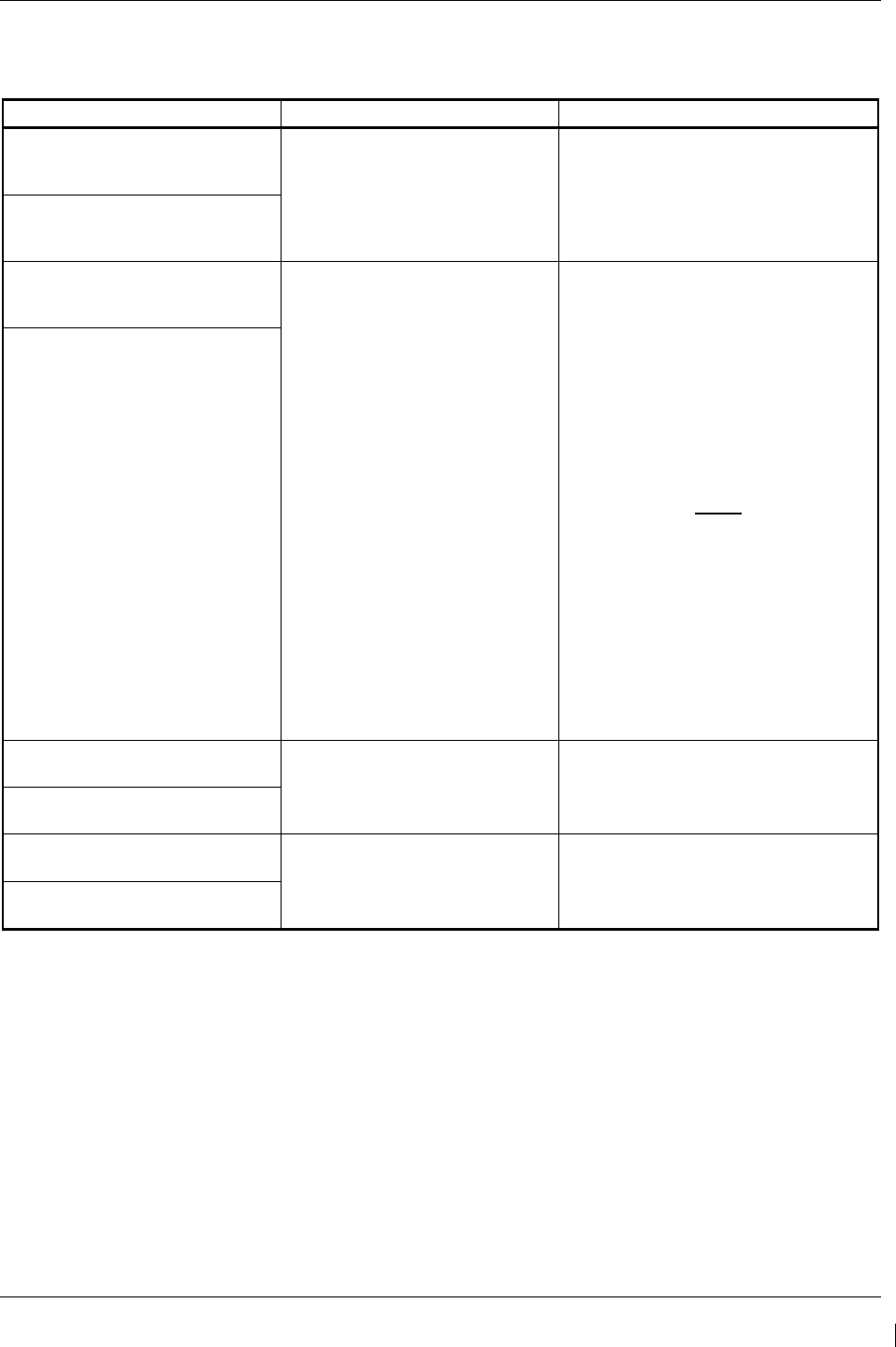
G1000/GFC700 System Maintenance Manual – C90A/C90GT/C90GTi King Air Page 5-67
190-00682-01 Revision G
5.13 GTX Troubleshooting
5.13.1 GTX Alerts
Failure Message Cause Solutions
MANIFEST – GTX1 software
mismatch. Communication
halted. The system has detected an
incorrect software version loaded
in the specified GTX 33.
•
Reload software. See Section 3.9
for the Software Load Procedure.
MANIFEST – GTX2 software
mismatch. Communication
halted.
XPDR1 CONFIG – XPDR1
configuration error. Config service
req’d.
The system has detected a
configuration mismatch for the
specified GTX 33.
• Perform a SET>ACTV
configuration reset on the GTX
Config page and verify the aircraft
registration is present.
• If error is still present, reload config
files from a loader card.
√ If problem persists, replace
master configuration module,
check config module harness
for faults and replace if
necessary.
NOTE
New Terrain/Obstacle cards, Jeppesen
Aviation Database and other optional
features (i.e. TAWS unlock card) will
need to be replaced if the master
configuration module is changed. The
G1000 System ID number will change
to a new number when installing a new
master config module. The old Terrain
and other cards will no longer work as
they will remain locked to the old
System ID number.
XPDR2 CONFIG – XPDR2
configuration error. Config service
req’d.
XPDR1 SRVC – XPDR1 needs
service. Return unit for repair. The G1000 has detected a failure
in the specified GTX 33. • Replace GTX 33.
XPDR2 SRVC – XPDR2 needs
service. Return unit for repair.
XPDR1 FAIL – XPDR 1 is
inoperative. The specified GTX 33 is not
responding.
• Check wiring between GIA’s and
GTX.
• Replace GTX 33.
XPDR2 FAIL – XPDR 2 is
inoperative.

Page 5-68 G1000/GFC700 System Maintenance Manual – C90A/C90GT/C90GTi King Air
Revision G 190-00682-01
5.14 GDL 69A Troubleshooting
5.14.1 GDL 69A Common Problems
Symptom Recommended Action
No XM audio is heard
• Ensure the following items are not preventing the audio panel
from distributing XM audio (reference applicable G1000 Pilot’s
Guide):
√ Verify the XM volume is not muted on the AUX – XM RADIO
page on the MFD.
√ Verify the COM squelch is not open.
√ Verify the ICS squelch is not open.
√ Verify the marker beacon tones are not being received.
√ Verify the headphone (if equipped) volume is turned up.
• Go to the AUX – SYSTEM STATUS page on the MFD and
ensure unit is online.
√ If a red X is present, verify the unit is receiving power at the
rack connector.
• Ensure there are no GDL alerts in the alert window. If there is
an Alert for software or configuration error or mismatch, reload
the file noted in the Alert.
• Restart the PFD’s and MFD in configuration mode and go to the
GDL page.
√ Verify unit is active.
√ Verify the Signal number is “2” or “3”. If it is “0” or “1” check
the GDL 69/69A antenna and cabling for faults.
√ Reseat the GDL 69/69A to verify the coax connector is
fully seated.
√ If unit is not active, contact XM Customer service at 1-800-
985-9200 to have a refresh signal sent to your unit. You will
need to provide them the Audio Radio ID (and Data Radio
ID number for XM weather) numbers. Also verify with XM
that the correct Weather package (Aviator Lite or Aviator) is
on the account, and that no traffic service has been
activated against that Radio ID. The unit must be on for
approximately one hour after the request for the refresh has
been sent to receive the signal.
√ Alternatively, you may also go to XM’s website at
http://www.xmradio.com/refresh/ and enter the radio ID’s to
have a refresh signal sent.
√ If there is still problems receiving weather products after
performing the above step, call XM and have the account
deactivated, and a new account activated to clear out any
corrupt account information.
√ Verify there is a good ground connection through the aircraft
between the MFD and the GDL69/69A unit. Reference the
Aircraft Maintenance Manual for instructions on how to
check bonding and ground points.
√ If problem persists, replace the GDL 69/69A.
No XM weather information is
displayed

G1000/GFC700 System Maintenance Manual – C90A/C90GT/C90GTi King Air Page 5-69
190-00682-01 Revision G
5.14.2 GDL 69A Alerts
Failure Message Cause Solutions
GDL 69 FAIL – GDL 69 has failed. The G1000 has detected a failure
in the GDL 69A.
• Replace GDL 69A.
• Check GDL 69A antenna and
cabling.
•
Check the GDL 69A and MFD
interconnect
.
GDL69 CONFIG – GDL 69
configuration error. Config service
req’d.
The G1000 has detected a GDL
69A configuration mismatch.
• Reload configuration file. See
Section 3.9 for the Configuration
Procedure.
• If problem persists, replace
master configuration module,
check config module harness
for faults and replace if
necessary.
NOTE
New Terrain/Obstacle cards, Jeppesen
Aviation Database and other optional
features (i.e. TAWS unlock card) will
need to be replaced if the master
configuration module is changed. The
G1000 System ID number will change
to a new number when installing a new
master config module. The old Terrain
and other cards will no longer work as
they will remain locked to the old
System ID number.
MANIFEST – GDL software
mismatch. Communication
halted.
The system has detected an
incorrect software version loaded
in the GDL 69A.
• Load correct software version.
See Section 3.9 for the
Software Load Procedure.

Page 5-70 G1000/GFC700 System Maintenance Manual – C90A/C90GT/C90GTi King Air
Revision G 190-00682-01
5.15 GRS 77/GMU 44 Troubleshooting
5.15.1 AHRS Common Problems
Symptom Recommended Action
AHRS does not complete
initialization
• Ensure that a cell phone or a device using cell phone technology is not
turned on (even in a monitoring state) in the cabin.
• Ensure GPS has acquired at least four satellites, has a 3D navigation
solution, and a DOP of less than 5.0. This is particularly important if
this issue appears during ground operation only.
• Calibrate the GRS 77.
• Check GRS 77 configuration module wiring for damage.
• Check GRS 77 connector for bent pins.
• If no damage can be found, replace GRS 77 configuration module.
•
If problem persists, replace the GRS 77.
Attitude appears unstable
• Ensure that a cell phone or a device using cell phone technology is not
turned on (even in a monitoring state) in the cabin.
• Ensure the four GRS 77 mounting screws are tight. Finger tight is not
sufficient, a screwdriver must be used to verify.
• Ensure mounting rack and airframe shelf are secure and all hardware
and brackets are present (CAUTION - do not loosen the mounting rack
hardware to the airframe shelf or the aircraft will need to be re-leveled
and the PITCH/ROLL OFFSET procedure performed)..
• Ensure GRS 77 connector is securely fastened and proper strain relief
is provided.
• Remove GRS 77 connector and verify there are no bent pins.
• Replace the GRS 77.
•
Contact Garmin for further troubleshooting if required.

G1000/GFC700 System Maintenance Manual – C90A/C90GT/C90GTi King Air Page 5-71
190-00682-01 Revision G
5.15.2 GRS Alerts
Failure Message Cause Solutions
MANIFEST – GRS1 software
mismatch. Communication
halted. The system has detected an
incorrect software version loaded
in the specified GRS 77.
• Load correct software version. See
Section 3.9 for the Software Load
Procedure.
MANIFEST – GRS2 software
mismatch. Communication
halted.
AHRS1 SERVICE – AHRS1
magnetic-field model needs
update. The AHRS magnetic field model
should be updated for the
specified unit. Appears on ground
only.
• Load updated AHRS magnetic field
file. See Section 4.6.
AHRS2 SERVICE – AHRS2
magnetic-field model needs
update.
GEO LIMITS – AHRS1 too far
north/south, no magnetic
compass. No magnetic compass information
available due to being too far
north or south.
• Operate the aircraft only within the
limits as specified in the G1000/GFC
700, King Air C90A/C90GT/C90GTi
AFMS, listed in Table 1-3
GEO LIMITS – AHRS2 too far
north/south, no magnetic
compass.
AHRS1 TAS – AHRS1 not
receiving airspeed. The specified GRS 77 is not
receiving airspeed from the GDC
74A.
• Check GRS/GDC interconnect for
faults.
• Replace the GDC 74:
• If problem persists, replace the GRS
77.
AHRS2 TAS – AHRS2 not
receiving airspeed.
AHRS1 GPS – AHRS1 not
receiving backup GPS
information.
The GRS 77 #1 is not receiving
backup GPS information from
either GIA 63.
• Ensure that a cell phone or a device
using cell phone technology is not
turned on (even in a monitoring
state) in the cabin.
• Check GPS status for GIA 1 and 2
on MFD - AUX GPS STATUS page.
If one or both GPS receivers cannot
acquire a position lock, see GPS
troubleshooting section
• Troubleshoot GIA1/2 –GRS1 wiring
for faults (ref. Failed Path
troubleshooting section).
• Replace the GRS 77 #1.
AHRS1 GPS – AHRS1 operating
exclusively in no-GPS mode.
The GRS 77 #1 is operating in the
absence of GPS.
AHRS1 GPS – AHRS1 not
receiving any GPS information.
The GRS 77 #1 is not receiving
GPS data from the GPS receivers.
AHRS1 GPS – AHRS1 using
backup GPS source.
The GRS 77 #1 is using the
backup GPS data path.
AHRS2 GPS – AHRS2 not
receiving backup GPS
information.
The GRS 77 #2 is not receiving
backup GPS information from
either GIA 63.
• Ensure that a cell phone or a device
using cell phone technology is not
turned on (even in a monitoring
state) in the cabin.
• Check GPS status for GIA 1 and 2
on MFD - AUX GPS STATUS page.
If one or both GPS receivers cannot
acquire a position lock, see GPS
troubleshooting section
• Troubleshoot GIA1/2 –GRS2 wiring
for faults (ref. Failed Path
troubleshooting section).
• Replace the GRS 77 #2
AHRS2 GPS – AHRS2 operating
exclusively in no-GPS mode.
The GRS 77 #2 is operating in the
absence of GPS.
AHRS2 GPS – AHRS2 not
receiving any GPS information.
The GRS 77 #2 is not receiving
GPS data from the GPS receivers.
AHRS2 GPS – AHRS2 using
backup GPS source.
The GRS 77 #2 is using the
backup GPS data path.
AHRS MAG DB – AHRS magnetic
model database version
mismatch.
The G1000 has detected a
magnetic model database version
mismatch.
• Load AHRS magnetic model field in
both GRS units.

Page 5-72 G1000/GFC700 System Maintenance Manual – C90A/C90GT/C90GTi King Air
Revision G 190-00682-01
Failure Message Cause Solutions
MAG VAR WARN – Large
magnetic variance. Verify all
course angles.
Magnetic variance value from
GMU 44 is not accurate.
• If flying near large radio towers or
other sources of possible
electromagnetic interference, the
condition should correct itself as the
aircraft leaves the area.
• If problem persists, run magnetic
interference check in Section 5.15.4
to check for magnetic interference in
the aircraft.
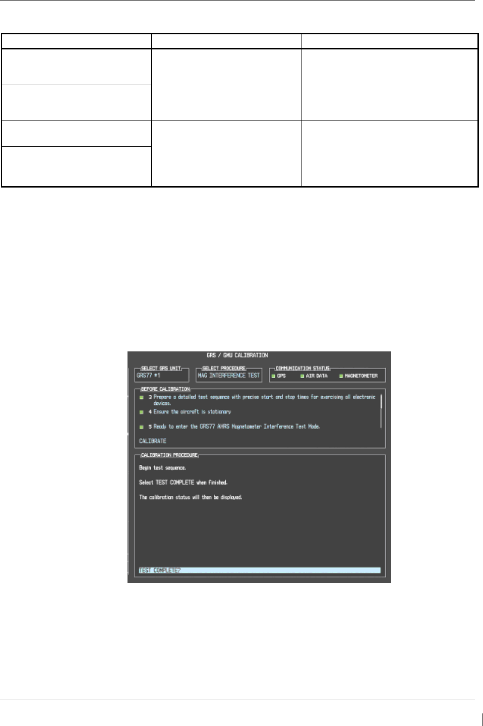
G1000/GFC700 System Maintenance Manual – C90A/C90GT/C90GTi King Air Page 5-73
190-00682-01 Revision G
5.15.3 GMU Alerts
Failure Message Cause Solutions
MANIFEST – GMU1 software
mismatch. Communication
halted. The system has detected an
incorrect software version loaded
in the specified GMU 44.
Load the correct software version. See
Section 3.9 for the Software Load
Procedure.
MANIFEST – GMU2 software
mismatch. Communication
halted.
HDG FAULT – AHRS1
magnetometer fault has occurred A fault has occurred in the
specified magnetometer; heading
will be flagged invalid.
• Check GMU 44/GRS 77
interconnect for faults.
Replace GMU 44.
If problem persists, replace
GRS 77.
HDG FAULT – AHRS2
magnetometer fault has occurred.
5.15.4 Calibration Procedure E: Magnetometer Interference Test
A magnetometer interference test is available for troubleshooting and/or verifying a magnetically ‘clean’
installation of the GMU 44. This test exercises various devices on the aircraft that could potentially affect
the magnetic field as measured by the GMU 44.
NOTE
This test is used to validate that no electronic device interferes with the operation of the
GMU 44 magnetometer. It is highly recommended that this test be performed after
installation or maintenance of electrical components on the aircraft and/or for
troubleshooting the GMU 44.
Figure 5-7. Magnetometer Interference Test
1. Initiate the AHRS magnetometer interference test procedure by performing the following steps:
2. Enter Configuration Mode and go to GRS/GMU Calibration page as shown in Figure 5-7.
Page 5-74 G1000/GFC700 System Maintenance Manual – C90A/C90GT/C90GTi King Air
Revision G 190-00682-01
3. This page is protected and requires a keystroke password to perform this test. Press the following
softkeys in sequence:
i) softkey 9
ii) softkey 10
iii) softkey 11
iv) softkey 12
4. Select MAG INTERFERENCE TEST and press the ENT key.
5. Follow the checklist items displayed on the PFD, and press the ENT key as each one is completed
or confirmed.
NOTE
The 3
rd
item on the checklist instructs the operator to “prepare a detailed test sequence
with precise start and stop times for exercising all electronic devices”. The list of
relevant electronic devices are given in Table 5-5. Begin test with flaps retracted, flight
controls in a neutral position and all lights selected OFF.
Table 5-5. Magnetometer Interference Test Sequence (Example)
Elapsed Time
since Start of
Test (min:secs)
Action
0:00 Test begins
0:10 Navigation lights on
0:20 Navigation lights off
0:30 Landing lights on
0:40 Landing lights off
0:50 Taxi lights on
1:00 Taxi lights off
1:20 Strobes on
1:40 Strobes off
1:50 Recognition lights on
2:00 Recognition lights off
2:10 Tail flood lights on
2:20 Tail flood lights off
2:30 Beacon on
2:40 Beacon off
2:50 Rudder full left
3:00 Rudder full right
3:10 Rudder trim left
3:20 Rudder trim right
3:30 Elevator full nose UP
3:40 Elevator full nose DN
3:50 End of test
6. When the CALIBRATE field is blinking, press the ENT key to begin the procedure, and have a
stopwatch ready to begin recording the elapsed time.
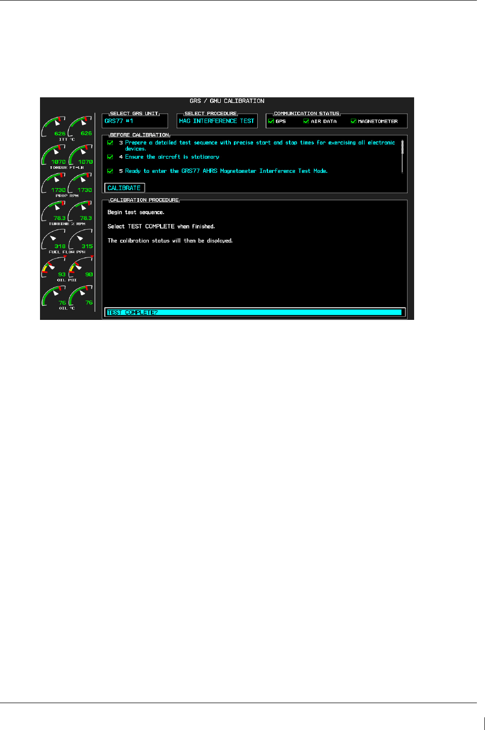
G1000/GFC700 System Maintenance Manual – C90A/C90GT/C90GTi King Air Page 5-75
190-00682-01 Revision G
NOTE
It is important that the “time equals zero” moment corresponds with the moment the PFD
first displays the blinking TEST COMPLETE? message.
Figure 5-8. Magnetometer Interference Test Complete
7. The operator should carry out the actions called for in the prepared test sequence.
NOTE
It is important that all actions are carried out in the order and at the precise elapsed time
as specified in the prepared test sequence.
8. When the operator has completed the actions specified in the test sequence, press the ENTER
button to indicate that the process is complete. When this is done, the TEST COMPLETE field
stops blinking.
9. The PFD informs the operator if the installation has passed or failed the magnetometer
interference test. If the test passes, no further action is required for this test.
If the test fails, the installation should be considered unreliable until the source of magnetic
interference is identified and remedied. When the magnetometer interference test fails, record the
three magnetometer maximum deviation values and their corresponding timestamps. Any
maximum deviation value greater than 2.5 milliGauss indicates a problem that must be resolved.
Compare the corresponding timestamps with the prepared test sequence to identify which action
produced the problem. Contact Garmin for assistance in resolving the problem.
NOTE
Two common reasons for a failed magnetometer interference test are: 1) new equipment
is installed in close proximity to the GMU 44 magnetometer, and 2) an existing or new
electronic device has become grounded through the aircraft structure instead of via the
proper ground wire in a twisted shielded pair.
10. Press the ENT key on the PFD to conclude this procedure.

Page 5-76 G1000/GFC700 System Maintenance Manual – C90A/C90GT/C90GTi King Air
Revision G 190-00682-01
5.16 GDC 74B Troubleshooting
5.16.1 Air Data Common Problems
Symptom Recommended Action
Altitude is different than standby
altimeter
• Perform a pitot/static check per Section 7.6 of this manual. Allow
the GDC to warm up for fifteen minutes before checking
accuracy, per Garmin Service Advisory 0606.
•
Determine which instrument is outside limits and replace. The
GDC may be field adjusted per Garmin Service Advisory 0720.
Note: Both units may individually be in spec but show a
difference in altitude. Do not return the GDC to Garmin for
service if not outside limits.
GDC Config file does not load.
• Replace GDC config module.
√
If problem persists, replace GDC config module wire harness.
5.16.2 GDC 74B Alerts
Failure Message Cause Solutions
MANIFEST – GDC1 software
mismatch Communication halted. The system has detected an
incorrect software version loaded
in the specified GDC 74B.
•
Load correct software version.
See Section 3.9 for the Software
Load Procedure.
MANIFEST – GDC2 software
mismatch Communication halted.
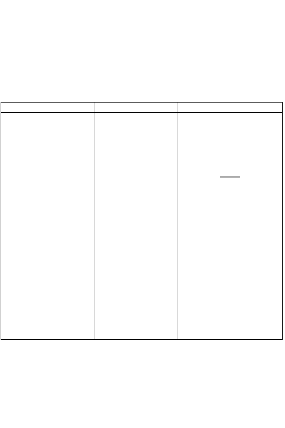
G1000/GFC700 System Maintenance Manual – C90A/C90GT/C90GTi King Air Page 5-77
190-00682-01 Revision G
5.17 GWX 68 Troubleshooting
5.17.1 GWX 68 Alerts and Problems
WARNING:
Before energizing the equipment, be sure microwave radiation safety precautions
including both fuel and personnel safety considerations have been observed. These
include clearing all personnel to an area beyond the maximum permissible exposure level
(MPEL) boundary. The MPEL for the GWX 68 is 11 feet.
Failure Message Cause Solutions
GWX CONFIG – GWX configuration
error. Configuration service
required.
The G1000 has detected a
GWX 68 configuration
mismatch.
• Load GWX configuration files,
√ Replace GWX.
√ If problem persists, replace
master configuration
module, check config
module wiring for faults
and replace if necessary.
NOTE
New Terrain/Obstacle cards,
Jeppesen Aviation Database and
other optional features (i.e.
TAWS unlock card) will need to
be replaced if the master
configuration module is changed.
The G1000 System ID number
will change to a new number
when installing a new master
config module. The old Terrain
and other cards will no longer
work as they will remain locked
to the old System ID number.
GWX FAIL – GWX is inoperative. The G1000 has detected a
failure in the GWX 68.
• Check Ethernet connection
between the GWX and GDL69A
for faults.
•
Replace the GWX 68
GWX SERVICE – Needs service.
Return unit for repair.
The G1000 has detected a
failure in GWX 68. • Replace the GWX 68.
MANIFEST – GWX software
mismatch. Communication halted.
The system has detected an
incorrect software version
loaded in the GWX 68.
• Load correct software version. See
Section 3.9 for the Software Load
Procedure.

Page 5-78 G1000/GFC700 System Maintenance Manual – C90A/C90GT/C90GTi King Air
Revision G 190-00682-01
5.18 GMC 710 Troubleshooting
5.18.1 GMC 710 Alerts and Problems
Failure Message Cause Solutions
GMC CNFG – GMC Config error.
Config service req’d.
The G1000 has detected a
GMC 710 configuration
mismatch.
• Load GMC configuration files,
√ Replace GMC.
√ If problem persists, replace
master configuration
module, check config
module wiring for faults
and replace if necessary.
NOTE
New Terrain/Obstacle cards,
Jeppesen Aviation Database and
other optional features (i.e.
TAWS unlock card) will need to
be replaced if the master
configuration module is changed.
The G1000 System ID number
will change to a new number
when installing a new master
config module. The old Terrain
and other cards will no longer
work as they will remain locked
to the old System ID number.
GMC FAIL – GMC is inoperative. The G1000 has detected a
failure in the GMC 710.
• Check wiring for faults (ref Failed
Path troubleshooting section).
• Replace the GMC 710.
MANIFEST – GMC software
mismatch. Communication halted.
The system has detected an
incorrect software version
loaded in the GMC 710.
• Load the correct software version.
See Section 3.9 for the Software
Load Procedure.

G1000/GFC700 System Maintenance Manual – C90A/C90GT/C90GTi King Air Page 5-79
190-00682-01 Revision G
5.19 GCU 475 Troubleshooting
5.19.1 GCU 475 Alerts and Problems
Failure Message Cause Solutions
GCU CNFG – GCU Config error.
Config service req’d.
The G1000 has detected a
GCU 475 configuration
mismatch.
• Load GCU configuration files,
√ Replace GCU.
√ If problem persists, replace
master configuration
module, check config
module wiring for faults
and replace if necessary.
NOTE
New Terrain/Obstacle cards,
Jeppesen Aviation Database and
other optional features (i.e.
TAWS unlock card) will need to
be replaced if the master
configuration module is changed.
The G1000 System ID number
will change to a new number
when installing a new master
config module. The old Terrain
and other cards will no longer
work as they will remain locked
to the old System ID number.
GCU FAIL – GCU is inoperative. The G1000 has detected a
failure in the GCU 475.
• Check wiring for faults (ref Failed
Path troubleshooting section).
• Replace the GCU 475.
MANIFEST – GCU software
mismatch. Communication halted.
The system has detected an
incorrect software version
loaded in GCU 475.
• Load the correct software version.
See Section 3.9 for the Software
Load Procedure.
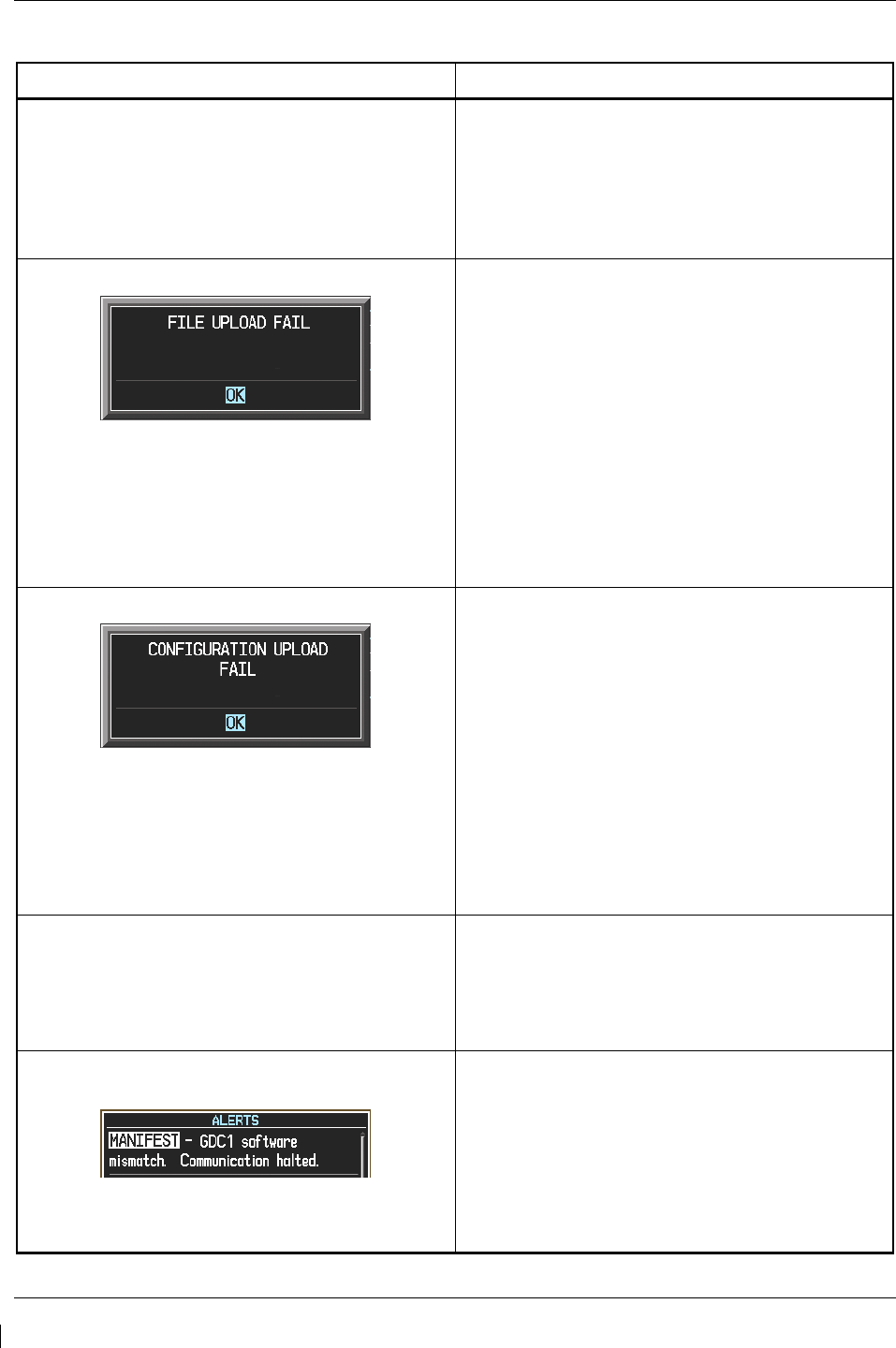
Page 5-80 G1000/GFC700 System Maintenance Manual – C90A/C90GT/C90GTi King Air
Revision G 190-00682-01
5.20 Software/Configuration Troubleshooting
Problem Solutions
MFD or PFD displays do not power up:
•
Ensure that the criteria listed in Section 5.20.1
are fulfilled for the applicable situation.
•
Ensure power is present at display backshell
connector.
•
Troubleshoot per the “Blank Display” GDU
section..
Software file load fails:
•
Ensure that criteria listed in Section 5.20.1 are
fulfilled for the applicable situation.
•
Ensure that LRU is reporting data on System
Status page (LRU is ‘ONLINE’). Check data
path wiring as needed.
•
Retry software file load or try using a different
card. Ensure that the MFD is not touched
during the loading process.
•
Ensure that LRU part number is compatible
with software version and Card Loader. Refer
to the General Arrangement Drawing and to
Section 3.8 of this document.
•
Replace LRU.
Configuration file load fails:
•
Ensure that the criteria listed in Section 5.20.1
are fulfilled for the applicable situation.
•
Ensure that LRU is reporting data on System
Status page (LRU is ‘ONLINE’). Check data
path wiring as needed.
•
Retry configuration file load or try using a
different card. Ensure that the MFD is not
touched during the loading process.
•
Ensure that LRU part number is compatible
with Card Loader. Refer to the General
Arrangement Drawing and to Section 3.8 of this
document.
•
Replace LRU.
GIA1 and/or GIA2 to ‘LRU’ data path not working
•
Ensure that the criteria listed in Section 5.20.1
are fulfilled for the applicable situation.
•
Ensure GIA1 and GIA2 are configured
correctly.
•
Check wiring, connectors & pins as needed.
Software File Mismatch Alert appears in lower
right corner of PFD when started in normal mode:
•
Ensure that proper software file part number
and version were loaded to LRU. Refer to the
General Arrangement Drawing and to Section
5.20.1.
•
Check and ensure that correct Card Loader
was used during load process. Refer to the
General Arrangement Drawing.
•
Reload software to LRU.

G1000/GFC700 System Maintenance Manual – C90A/C90GT/C90GTi King Air Page 5-81
190-00682-01 Revision G
5.20.1 System Communication Hierarchy
The following criteria must be satisfied to be able to perform the desired operation:
Desired Operation Criteria for Success
Load Software to MFD or PFD Displays
•
SW Loader Card must be inserted in top slot
for each display to be loaded.
•
CLR & ENT keys must be held during power
up of display.
•
Power on only one display at a time during
software loading.
Load AIRFRAME, SYSTEM, MFD1, PFD 1, PFD
2 and MANIFEST configuration files to MFD and
PFDs
•
SW Loader Card must be inserted in top slot
of PFD 1.
•
PFD 1 and MFD must be powered on.
•
PFD 1 and MFD must have correct software.
Load Software/Configuration files to GIA 63Ws
•
SW Loader Card must be inserted in top slot
of PFD 1.
•
G1000 system must be powered on.
•
PFD and MFD must have correct software.
•
PFD 1 and MFD must be successfully
configured with AIRFRAME, SYSTEM,
MANIFEST, MFD1, PFD 1 and PFD 2
configuration files.
Load Software/Configuration files to:
- GMA 1347D
- GDC 74B
- GEA 71
- GRS 77 (software only)
- GMU 44 (software only)
- GTX 33( )
•
SW Loader Card must be inserted into PFD 1
top slot.
•
G1000 must be powered on.
•
PFD 1 and MFD must have correct software
and configuration settings.
•
GIA 63Ws must have correct software.
•
GIA 63Ws must be successfully configured
with GIA1 and GIA2 configuration files.
•
Data path from GIA1 to each LRU must be
operational.
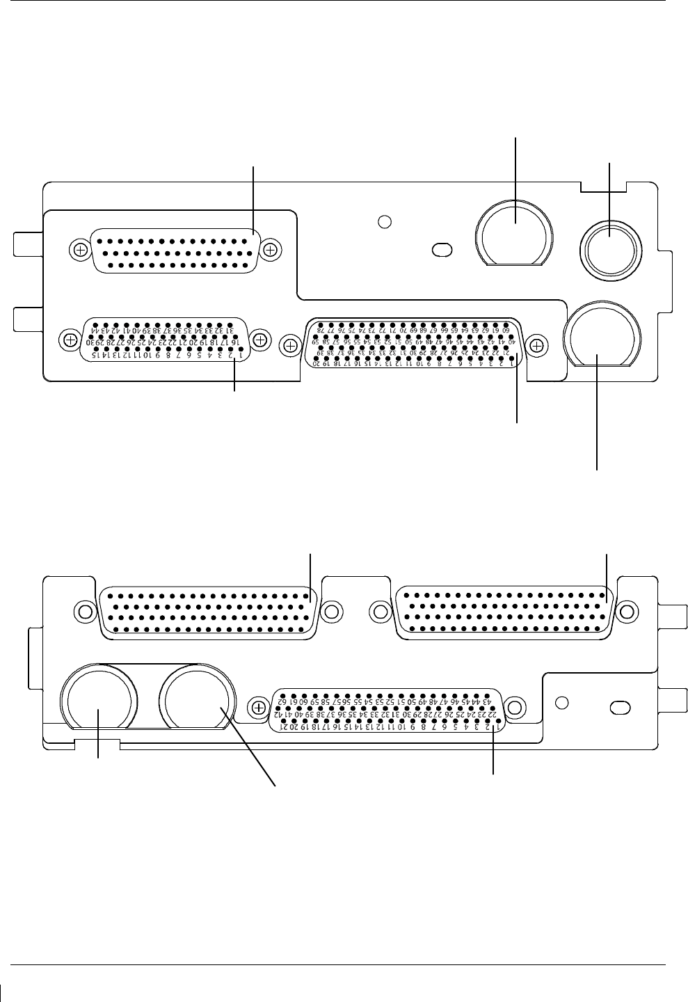
Page 5-82 G1000/GFC700 System Maintenance Manual – C90A/C90GT/C90GTi King Air
Revision G 190-00682-01
5.21 Backshell Connectors
The following figures depict the backshell connectors as viewed with the LRU removed.
1 2 3
16 17
4 5 6 7 8 9 10 11 12 13 14 15
1819 20 21 2223 24 2526 2728 2930
31 32 3334 35 36 37 3839 40 41 42 43 44
1 2 3 4 5 6 7 89 10 11 12 13 14 15 16 17 18 19 20
21 22 23 24 25 26 27 28 29 30 31 32 33 34 35 36 37 38 39
40 41 42 43 44 45 46 47 48 49 50 51 52 53 54 55 56 57 58 59
60 61 62 63 64 65 66 67 68 69 70 71 72 73 74 75 76 77 78
1 2 3 4 5 6 7 8 9 10 11 12 13 14 15 16 17 18 19 20
21 22 23 24 25 26 27 28 29 30 31 32 33 34 35 36 37 38 39
40 41 42 43 44 45 46 47 48 49 50 51 52 53 54 55 56 57 58 59
60 61 62 63 64 65 66 67 68 69 70 71 72 73 74 75 76 77 78
COM BOARD CONNECTOR (P601)
COM ANTENNA CONNECTOR
COOLING PORT
MAIN DISCRETE CONNECTOR (P604)
MAIN SERIAL CONNECTOR (P603)
GPS ANTENNA CONNECTOR
I/O CONNECTOR #2 (P606) I/O CONNECTOR #1 (P605)
G/S ANTENNA CONNECTOR
NAV ANTENNA CONNECTOR
VOR/ILS CONNECTOR (P602)
Figure 5-9. GIA 63W Backshell Connectors
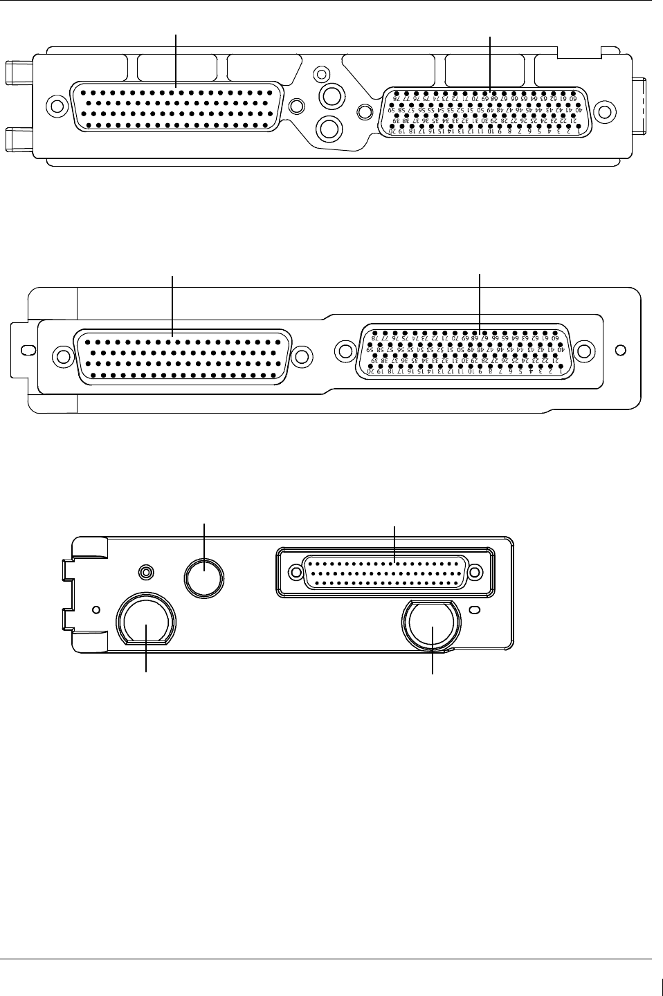
G1000/GFC700 System Maintenance Manual – C90A/C90GT/C90GTi King Air Page 5-83
190-00682-01 Revision G
Figure 5-10. GEA 71 Backshell Connectors
Figure 5-11. GMA 1347D Backshell Connectors
Figure 5-12. GTX 33/33D Backshell Connectors
1 2
3 4 5 6 7
8 9
10
11 12
13
14
15 16
17 18
19 20
21 22
23 24
25 26
27
28 29
30 31
32
33
34 35
36 37
38 39
40
41
42
43 44
45 46
47 48 49
50 51
52
53 54
55
56 57
58 59
60 61
62 63
64 65
66
67 68
69 70
71
72
73 74
75 76
77
78
P13471
P13472
1 2 3 4 5 6 7 8 91011
12
1314
15
16
17
18
1920
21
22
23
24
25
2627
28
29
30
31
32
33
34
3536
37
3839
40
41
42
4344
45
4647
48
4950
51
52
53
54
5556
57
5859
6061
6263
64
6566
67
6869
70
71
72
73
74
75
76
7778
P712 P711
1 2 3
4
5 6 7
8
9 10 11 12 13 14 15 16 17 18 19 20
21
22 2324 25 26 2728 29 30 3132 33 34 3536 37 38 39 40
41 42
43 44
45 46 47 48
49 50 51 52 53 54 55 5657 58 59 6061 62
TOP ANTENNA CONNECTOR
BOTTOM ANTENNA CONNECTOR
P331
COOLING
PORT
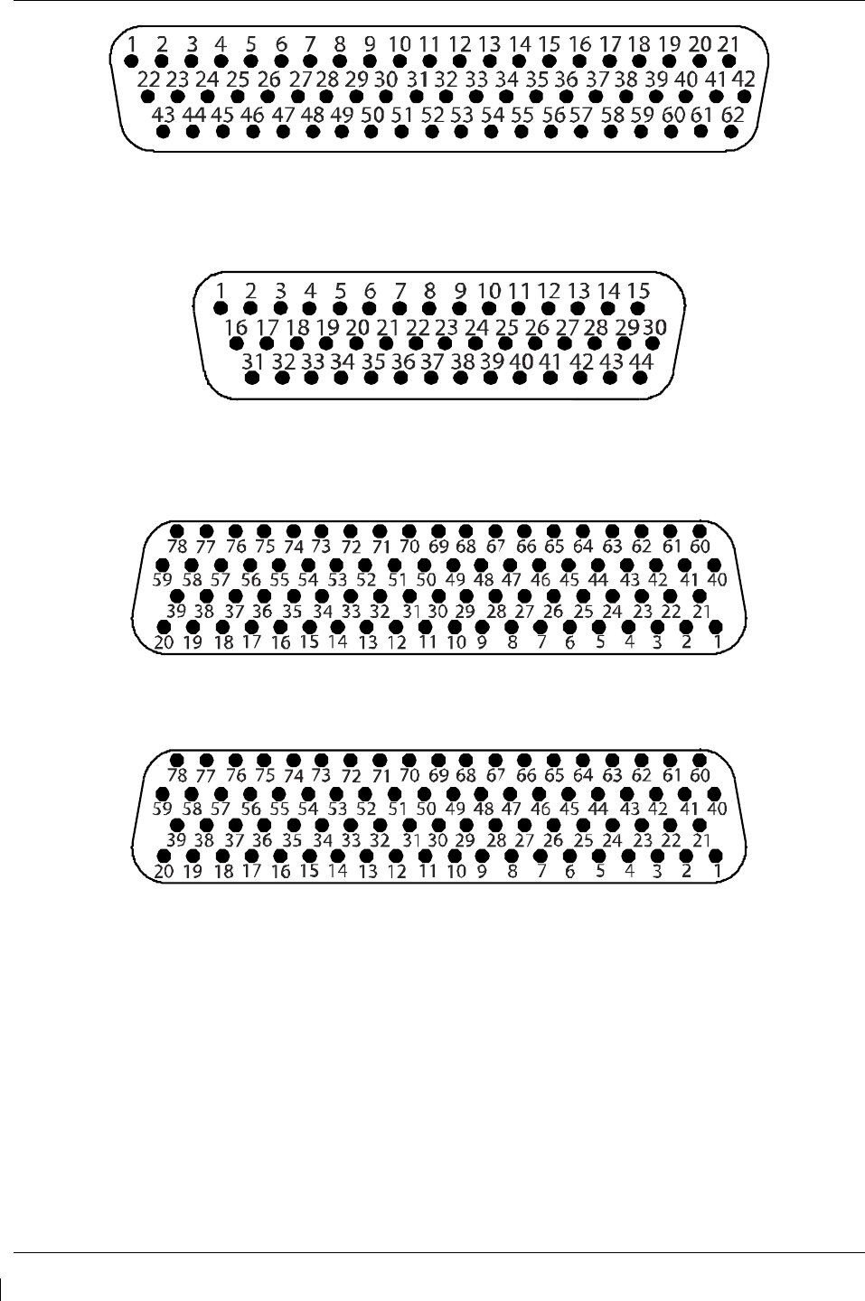
Page 5-84 G1000/GFC700 System Maintenance Manual – C90A/C90GT/C90GTi King Air
Revision G 190-00682-01
Figure 5-13. GDU 1040A/1500 Backshell Connector (P10401 or P15001)
Figure 5-14. GRS 77 Backshell Connector (P771)
Figure 5-15. GDC 74B Backshell Connector (P74B1)
Figure 5-16. GDL 69A Backshell Connector (P69A1)
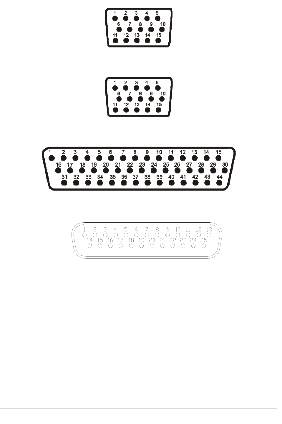
G1000/GFC700 System Maintenance Manual – C90A/C90GT/C90GTi King Air Page 5-85
190-00682-01 Revision G
Figure 5-17. GCU 475 Backshell Connector (P4751)
Figure 5-18. GMC 710 Backshell Connector (P7101)
Figure 5-19. GWX 68 Backshell Connector (P681)
Figure 5-20, Signal Conditioner Mating Connector (PVIB1)
(Rear View)

Page 5-86 G1000/GFC700 System Maintenance Manual – C90A/C90GT/C90GTi King Air
Revision G 190-00682-01
5.22 Standby Attitude Indicator Troubleshooting
5.22.1
Standby Attitude Indicator Common Problems
Symptom Recommended Action
Warning flag pops into view,
indicating that the gyro motor is
not receiving sufficient power to
operate
• Perform the Standby Instrument Electrical Power Checks in Section 8.1.5.
• Remove the unit per Section 6.25 and inspect the electrical connector.
• Check to ensure appropriate electrical power is being supplied to the
instrument.
√ If input electrical power is not adequate, troubleshoot the wiring
harness.
√ If input power is appropriate, the unit must be removed and
serviced by a qualified service facility See Section 6.25 for removal
instructions. Contact the manufacturer to find a qualified service
facility
Unit fails to perform to
specifications
• The unit must be removed and serviced by a qualified service facility.
See Section 6.25 for removal instructions. Contact the manufacturer to
find a qualified service facility.
5.23 Standby Airspeed Indicator Troubleshooting
5.23.1
Standby Airspeed Indicator Common Problems
Symptom Recommended Action
Airspeed Indicator lighting is
inoperative or malfunctioning
• Perform the Standby Instrument Electrical Power Checks in Section 8.1.5.
• Remove standby airspeed indicator per Section 6.23 and inspect the
electrical connector.
• Check that electrical power is being appropriately supplied to the
instrument.
√ If the input electrical power is not adequate, troubleshoot the wiring
harness.
√ If the input electrical power is appropriate, replace the standby
airspeed indicator or contact the manufacturer for further
troubleshooting.
Airspeed displayed is incorrect
• Using a pitot-static ramp tester, check airspeed displayed on standby
altimeter against airspeed display from ADC2.
√ If the airspeeds are the same, inspect the pitot/static ports and
associated equipment for faults.
√ If the airspeeds are different, replace the standby altimeter or
contact the manufacturer for further troubleshooting. See Section
6.23 for removal instructions.

G1000/GFC700 System Maintenance Manual – C90A/C90GT/C90GTi King Air Page 5-87
190-00682-01 Revision G
5.24 Standby Altimeter Troubleshooting
5.24.1
Standby Altimeter Common Problems
Symptom Recommended Action
Altimeter lighting is inoperative or
malfunctioning
• Perform the Standby Instrument Electrical Power Checks in Section 8.1.5.
• Remove standby altimeter per Section 6.24 and inspect the electrical
connector.
• Check that electrical power is being appropriately supplied to the
instrument.
√ If the input electrical power is not adequate, troubleshoot the wiring
harness.
√ If the input electrical power is appropriate, replace the standby
altimeter or contact the manufacturer for further troubleshooting.
Altimeter Vibrator is inoperative or
malfunctioning
Altitude displayed is incorrect
• Using a pitot-static ramp tester, check altitude displayed on standby
altimeter against altitude display from ADC2.
√ If the altitudes are the same, inspect the pitot/static ports and associated
equipment for faults.
√ If the altitudes are different, replace the standby altimeter or contact the
manufacturer for further troubleshooting. See Section 6.24 for removal
instructions.
5.25 Standby Battery Troubleshooting
Refer to King Air Series Component Maintenance Manual, listed in Table 1-2, for troubleshooting.

Page 5-88 G1000/GFC700 System Maintenance Manual – C90A/C90GT/C90GTi King Air
Revision G 190-00682-01
This page intentionally left blank.

G1000/GFC700 System Maintenance Manual – C90A/C90GT/C90GTi King Air Page 6-1
190-00682-01 Revision G
6 Equipment Removal & Replacement
This section describes how to remove and replace equipment in the King Air C90A/C90GT/C90GTi
associated with this STC. After removal and replacement, LRUs must be configured and tested as
described in Section 7.
CAUTION:
When removing and/or replacing any G1000 component, always ensure that aircraft
power is off. Unplug any auxiliary power supplies. Before performing maintenance, it is
required that the technician verify the LRU software part number and version number
matches the software configuration listed in the General Arrangement drawing, listed in
Table 1-2.
To check an LRU software part number and/or version, follow the procedure defined in Section 3.9.3.
If a faulty LRU is not reporting its software version and part number, check aircraft maintenance logs for
last software version loaded and verify against the General Arrangement drawing. The Software Manifest
page may also be used to check part numbers and versions.
The General Arrangement drawing allows alternate part number units to be installed with certain
hardware/software combination restrictions. Refer to the applicable “Garmin Equipment/Software List”
contained in the General Arrangement drawing for details.

Page 6-2 G1000/GFC700 System Maintenance Manual – C90A/C90GT/C90GTi King Air
Revision G 190-00682-01
6.1 GDU 1040A/1500
Removal:
1. Using a 3/32” hex tool, rotate all four ¼-turn fasteners counter-clockwise until they reach their
stops.
2. Carefully remove the display from the panel.
3. While supporting the display, disconnect the connector.
Reinstallation:
1. Visually inspect the connector and pins for signs of damage. Repair any damage. While
supporting the display, connect the connector to the rear of the unit.
2. Carefully insert the display into the panel cutout, ensuring that all 4 ¼-turn fasteners align with
the corresponding holes.
3. Seat the display in the panel cutout. Do not use excessive force while inserting the display.
4. Once seated, rotate all four ¼-turn fasteners clockwise to lock the display to the panel.
5. Configure and test the MFD and/or PFD according to Section 7.1.
6.2 GMA 1347D Audio Panel
Removal:
1. Using a 3/32” hex tool, turn the hex nut counter-clockwise until the GMA 1347D is unlocked
from its location.
2. Carefully remove the GMA 1347D from its rack.
Reinstallation:
1. Visually inspect the connectors to ensure there are no bent or damaged pins. Repair any
damage.
2. Gently insert the GMA 1347D into the rack until the locking tab engages the rack.
3. Begin to turn the hex nut clockwise. This draws the unit into the rack until seated. Do not
over-tighten the nut.
4. Configure and test the GMA 1347D according to Section 7.2.

G1000/GFC700 System Maintenance Manual – C90A/C90GT/C90GTi King Air Page 6-3
190-00682-01 Revision G
6.3 GIA 63W Integrated Avionics Units
Removal:
1. Gain access to the forward avionics compartment in the nose of the aircraft.
2. Unlock the GIA 63W handle by loosening the Phillips screw on the handle.
3. Pull the handle upward to unlock the GIA 63W. Gently remove the unit from the rack.
Reinstallation:
1. Visually inspect the connectors to ensure there are no bent or damaged pins. Repair any
damage.
2. Gently insert the GIA 63W into its rack. The handle should engage the dogleg track.
3. Press down on the GIA 63W handle to lock the unit into the rack.
4. Lock the handle to the GIA 63W body using the Philips screw.
5. Configure and test the GIA 63W(s) according to Section 7.3.
6.4 GEA 71 Engine/Airframe Unit
Removal:
1. Gain access by removing the appropriate GDU 1040A display unit (see Section 6.1.)
2. Unlock the GEA 71 handle by unscrewing the Phillips screw.
3. Firmly grasp the GEA 71 handle and pull it up vertically. This unlocks the unit from the
rack.
4. Gently remove the GEA 71 from its rack.
Reinstallation:
1. Visually inspect the connectors to ensure there are no bent or damaged pins. Repair any
damage.
2. Gently insert the GEA 71 into the rack. The handle should engage the dogleg track.
3. Press down on the handle to lock the unit into place.
4. Lock the handle to the GEA 71 body using the Philips screw.
5. Configure and test the GEA 71 according to Section 7.4.

Page 6-4 G1000/GFC700 System Maintenance Manual – C90A/C90GT/C90GTi King Air
Revision G 190-00682-01
6.5 GTX 33 Transponder
Removal:
1.
Gain access to the forward avionics compartment in the nose of the aircraft.
2.
Unlock the GTX 33 handle by loosening the Phillips screw on the handle.
3.
Pull the handle upward to unlock the GTX 33. Gently remove the unit from the rack.
Reinstallation:
1.
Visually inspect the connectors to ensure there are no bent or damaged pins. Repair any
damage.
2.
Gently insert the GTX 33 into its rack. The handle should engage the dogleg track.
3.
Press down on the GTX 33 handle to lock the unit into the rack.
4.
Lock the handle to the GTX 33 body using the Philips screw.
5.
Configure and test the GTX 33 according to Section 7.5.
6.6 GDC 74B Air Data Computer
Removal:
1. Gain access by removing the appropriate GDU 1040A display unit (see Section 6.1.)
2. Disconnect the pitot/static plumbing from the rear of the unit. Disconnect the single
connector.
3. Loosen each thumbscrew on the hold-down clamp and remove the clamp.
4. Carefully remove the unit from its mount.
Reinstallation:
1. Inspect the connector and pins for damage. Inspect the pitot/static plumbing for damage.
Repair any damage.
2. Place the unit in the mounting tray. Position the locking clamp and fasten using the
thumbscrews.
3. Connect the backshell assembly and pitot/static plumbing to the unit.
4. Configure and test the GDC 74B according to Section 7.6.
6.7 GTP 59 OAT Probe
Removal:
1. Using a deep-socket to hold the probe in place on the outside of the aircraft, loosen the GTP
59 mounting nut and remove the GTP 59.
Reinstallation:
1. Reinstallation is the reverse of removal.
2. No configuration is required for the GTP 59. Test according to Section 7.6.3.

G1000/GFC700 System Maintenance Manual – C90A/C90GT/C90GTi King Air Page 6-5
190-00682-01 Revision G
6.8 GRS 77 AHRS
Removal:
1. Gain access to the forward avionics compartment in the nose of the aircraft.
2. Disconnect the AHRS connector.
3. Remove the four Phillips thumbscrews with a screwdriver and set them aside.
4. Gently lift the GRS 77 from the mounting rack. (If the mounting rack is removed, the GRS 77
must be re-calibrated. Do not loosen mounting bolts. See Section 7.7)
Reinstallation:
1. Visually inspect the connectors to ensure there are no bent or damaged pins. Repair any
damage.
2. Place the GRS 77 on the mounting plate, ensuring the orientation is correct.
3. Fasten the unit to the plate using the Phillips thumbscrews.
4. Connect the connector to the GRS 77.
5. Calibrate, and test the GRS 77 according to Section 7.7.
6.9 GMU 44 Magnetometer
Removal:
1. Gain access to the GMU 44 units by removing the antenna panel located on the port side of the
vertical stabilizer.
2. Loosen three screws connecting the unit to the aircraft mounting bracket using a non-magnetic
Phillips screwdriver.
3. Disconnect the wiring harness.
Reinstallation
1. Visually inspect the connectors to ensure there are no bent or damaged pins. Repair any
damage. Connect the wiring harness to the GMU 44.
2. Fasten the GMU to the aircraft mounting bracket using a non-magnetic Phillips screwdriver.
3. Calibrate and test the GMU 44 according to Section 7.7.
6.10 GDL 69A
Removal:
1.
Gain access by removing the appropriate GDU 1040A display unit (see Section 6.1.)
2.
Unlock the GDL 69A handle by loosening the Phillips screw on the handle.
3.
Pull the handle upward to unlock the GDL 69A. Gently remove the unit from the rack.
Reinstallation:
1.
Visually inspect the connectors to ensure there are no bent or damaged pins. Repair any
damage.
2.
Gently insert the GDL 69A into its rack. The handle should engage the dogleg track.
3.
Press down on the GDL 69A handle to lock the unit into the rack.

Page 6-6 G1000/GFC700 System Maintenance Manual – C90A/C90GT/C90GTi King Air
Revision G 190-00682-01
4.
Lock the handle to the GDL 69A body using the Philips screw.
5.
Configure and test the GDL 69A according to Section 7.8.
6.11
GSA 80/81 Servos
Removal:
1. Gain access to the desired servo(s).
2. Disconnect the servo harness connector.
3. Use a socket or open-wrench to loosen and remove the servo attachment bolts. The Pitch-
Trim servo bracket will need to be removed to access all the Pitch-Trim servo attachment
bolts.
4. Carefully remove the servo and place a protective cover on the output gear.
5. Place a protective cover over the GSM 85A (or GSM 86) servo mount.
Reinstallation:
1. Inspect the output gear for abnormal wear or the absence of grease. If grease is required,
refer to Section 4.7 and grease the gear.
2. Carefully place the servo into the servo mount, ensuring proper orientation and alignment.
3. Fasten the servo to the servo mount using the existing hardware.
4. Inspect the harness connectors and check that no pins are bent or otherwise damaged.
Connect the harness and secure it appropriately.
5. If no further maintenance is required, continue to Section 7.9.
6.12 GSM 85A / GSM 86 Servo Mounts
Removal:
1. Remove the desired servo(s) per Section 6.11.
2. For the Roll, Pitch and Yaw Servos: remove the servo cable from the control cable clamps.
For the Pitch-Trim Servo: remove the servo cable from the outboard turnbuckle and Y-splice.
3. Use a socket or open-wrench to loosen and remove the servo attachment bolts.
4. Carefully remove the servo mount(s).
5. Remove the cable retention pins and ring (or cover) and then remove the servo cable from the
capstan.
Reinstallation:
1. Ensure cable retention pins are oriented correctly. Follow the installation instructions
provided in the respective servo installation drawing(s), listed in Table 1-2.
2. If no other maintenance is to be performed, reinstall the servo(s) per Section 6.11.

G1000/GFC700 System Maintenance Manual – C90A/C90GT/C90GTi King Air Page 6-7
190-00682-01 Revision G
6.13 GCU 475
Removal:
1. Use a 3/32” hex drive tool to turn each of the four locking sockets ¼ turn counterclockwise
until they reach their stops.
2. Disconnect backshell assembly from unit.
Reinstallation:
1. Inspect connector(s) for damaged pins.
2. Connect backshell assembly to unit.
3. Hold unit flush with the instrument panel, ensuring locking stud alignment marks are in the
vertical position.
4. Use a 3/32” hex drive tool to turn each of the four locking sockets ¼ turn clockwise. This
may require applying a small amount of forward pressure to engage the ¼ turn sockets.
5. Configure and test the GCU 475 according to Section 7.10.
6.14 GMC 710
Removal:
1. Use a 3/32” hex drive tool to turn each of the four locking sockets ¼ turn counterclockwise
until they reach their stops.
2. Disconnect backshell assembly from unit.
Reinstallation:
1. Inspect connector(s) for damaged pins.
2. Connect backshell assembly to unit.
3. Hold unit flush with the instrument panel, ensuring locking stud alignment marks are in the
vertical position.
4. Use a 3/32” hex drive tool to turn each of the four locking sockets ¼ turn clockwise. This
may require applying a small amount of forward pressure to engage the ¼ turn sockets.
5. Configure and test the GMC 710 according to Section 7.11.

Page 6-8 G1000/GFC700 System Maintenance Manual – C90A/C90GT/C90GTi King Air
Revision G 190-00682-01
6.15 GWX 68
Removal:
1. Gain access by removing nose radome.
2. Disconnect backshell assembly from unit.
3. Use a 3/16” hex drive tool to remove each of the four mounting screws.
Reinstallation:
1. Inspect connector for damaged pins.
2. Hold unit flush with the radar mount.
3. Use a 3/16” hex drive tool to tighten each of the four mounting screws.
4. Connect backshell assembly to unit.
5. Configure and test the GWX 68 according to Section 7.12.
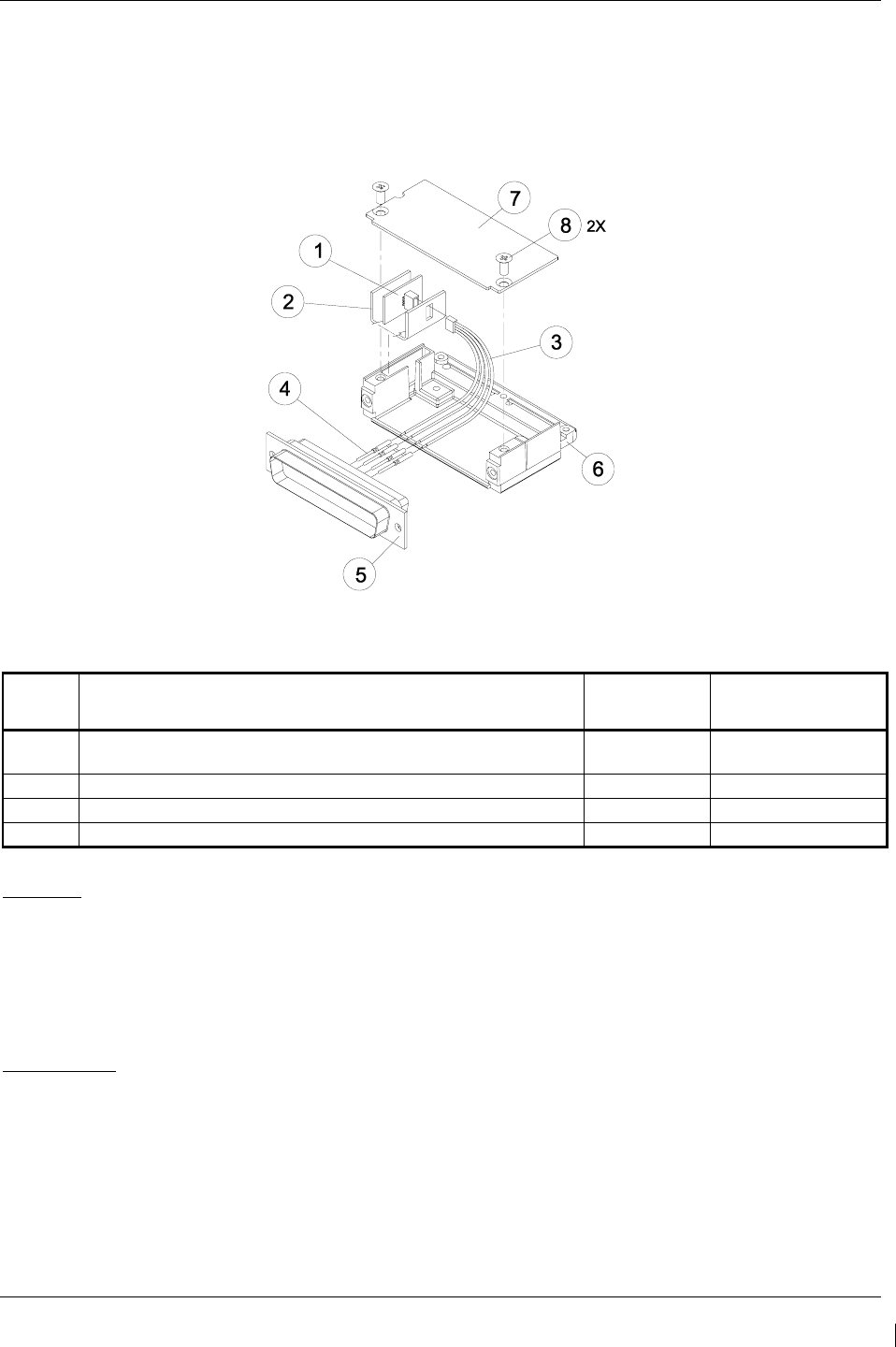
G1000/GFC700 System Maintenance Manual – C90A/C90GT/C90GTi King Air Page 6-9
190-00682-01 Revision G
6.16 Configuration Module Removal & Replacement
Configuration modules (Item 1 shown below) are located in the following LRU harness connector
backshells (Item 6): GDU 1040A PFD, GRS 77 AHRS, GDC 74B Air Data Computer, and the GEA 71
Engine/Airframe Unit. Refer to the Master Drawing List, listed in Table 1-2, for specific installation
drawings.
Figure 6-1. Configuration Module Installation
Table 6-1. Configuration Module Kit – 011-00979-00
Item Description Qty Needed Garmin Part
Number
1 Configuration Module PCB Board Assembly w/EEPROM & Temp
Sensor
1 012-00605-00
2 Spacer, Config Module 1 213-00043-00
3 Cable, 4-Conductor Harness 1 325-00122-00
4 Pins, #22 AWG (HD) 5 336-00021-00
Removal:
1. Disconnect connector from LRU.
2. Remove 2 screws (8) from cover (7) and remove cover.
3. Unplug connector from configuration module (1).
4. Remove configuration module.
Replacement:
1. Inspect connector for damaged pins (4).
2. Place configuration module (1) in position.
3. Insert connector into configuration module (1).
4. Assembly of the connector is the reverse of disassembly.
5. Continue to Section 6.16.1.

Page 6-10 G1000/GFC700 System Maintenance Manual – C90A/C90GT/C90GTi King Air
Revision G 190-00682-01
6.16.1
Configuration Module Checkout
If a GRS 77 AHRS Configuration Module is replaced:
All three GRS 77/GMU 44 calibration procedures must be performed. Proceed to Section 7.7.3.
If a GDC 74B Configuration Module is replaced:
Configuration settings must be reloaded to the GDC 74B. Proceed to Section 7.6.1.
If a GEA 71 Configuration Module is replaced:
Proceed to Section 7.4.1.
If only the Master Configuration Module is replaced:
NOTE
New Terrain/Obstacle cards, Jeppesen Aviation Database and other optional features (i.e.
TAWS unlock card) will need to be replaced if the master configuration module is
changed. The G1000 System ID number will change to a new number when installing a
new master config module. The old Terrain and other cards will no longer work as they
will remain locked to the old System ID number.
1. Start the G1000 system in configuration mode.
2. Go to the Configuration Upload Page on PFD 1.
3. Press the UPDT CFG softkey and press ENT.
If both PFD 1 and Master Configuration Module are replaced:
NOTE
New Terrain/Obstacle cards, Jeppesen Aviation Database and other optional features (i.e.
TAWS unlock card) will need to be replaced if the master configuration module is
changed. The G1000 System ID number will change to a new number when installing a
new master config module. The old Terrain and other cards will no longer work as they
will remain locked to the old System ID number.
1. The entire G1000 system must be re-configured. Insert the correct G1000 software loader card
into PFD 1.
2. Start the G1000 in configuration mode. Go to the System Upload Page on PFD 1.
3. See Section 3.9 for instructions on how to use the System Upload page. Check all configuration
files and reload them.
4. After reloading configuration files, examine the G1000 installation for any installed configuration
options. Options are listed in Section 3.9.4.3. Load optional files as necessary.
5. Continue to Section 8 and conduct the return to service checkout.
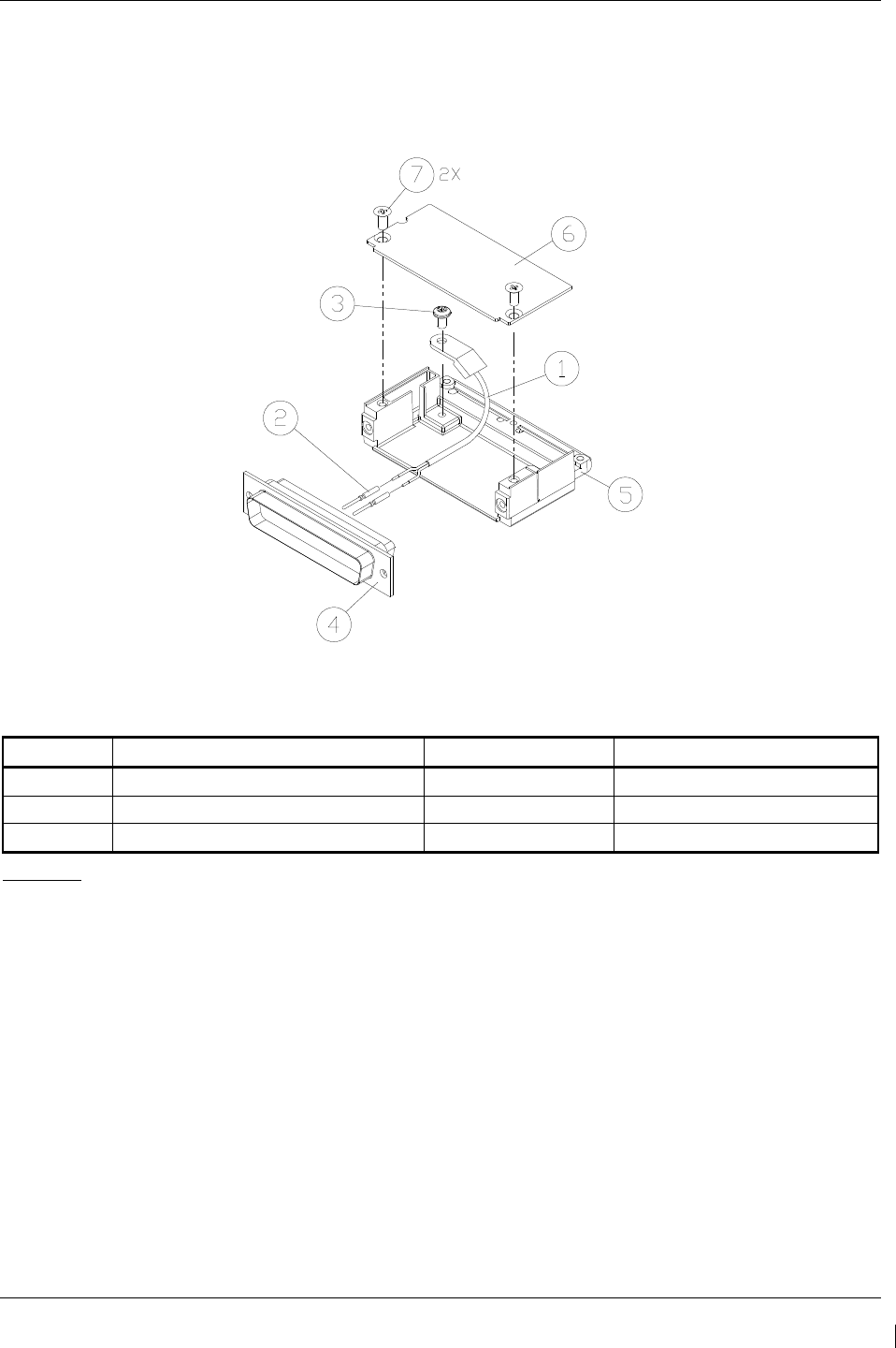
G1000/GFC700 System Maintenance Manual – C90A/C90GT/C90GTi King Air Page 6-11
190-00682-01 Revision G
6.17 GEA 71 Backshell Thermocouple Removal & Replacement
The GEA 71 has a K-Type thermocouple (Item 1 shown below) installed in its backshell, in addition to
the configuration module. The thermocouple is used in conjunction with the configuration module
temperature sensor to compensate for temperature probe errors resulting from the dissimilar metals at the
pin contacts.
Figure 6-2. GEA Backshell Thermocouple
Table 6-2. Thermocouple Kit (011-00981-00)
Item # Description Qty. Needed Garmin Part Number
1 3” Thermocouple, K type 1 925-L0000-00
2 Pins #22 AWG 2 336-00021-00
3 Screw 1 211-60234-08
Removal:
1. Remove GEA 71 per Section 6.4.
2. Remove GEA connector backplate.
3. Remove connector J711, item 5, from the backplate.
4. Remove cover, item 6 from the backshell.
5. Unscrew thermocouple from boss on backshell. Extract the thermocouple pins from the
connector.

Page 6-12 G1000/GFC700 System Maintenance Manual – C90A/C90GT/C90GTi King Air
Revision G 190-00682-01
Replacement:
1. Crimp pins, item 2, onto each of the thermocouple wires, item 1. Ensure that pre-stripped wire
length is 1/8” prior to crimping.
2. Insert newly crimped pins and wires into the appropriate connector housing location, item 4, as
specified by King Air C90 Wiring Diagram, listed in Table 1-2.
3. Place thermocouple body, item 1, onto the backshell boss, item 5. Place the thermocouple as
shown in Figure 6-2 so that the wires exit towards the bottom of the backshell.
4. Fasten thermocouple tightly to backshell using the provided screw, item 3.
5. Fasten cover, item 6, to backshell using the provided screws, item 7.
6. Continue to Section 7.4.1 and verify that the ITT indications are valid on the MFD.
6.18 GPS/WAAS Antennas
Remove and install the GPS/WAAS antennas in accordance with the antenna installation drawing (refer
to Master Drawing List, listed in Table 1-2, for specific drawing number). For procedural instructions on
accessing the GPS antennas, refer to the King Air Model 90 Series Maintenance Manual, listed in Table
1-2.
Proceed to Section 7.3.1 GPS Signal Acquisition for testing.
6.19 Engine Signal Conditioners
Removal:
1. For the Signal Conditioner No. 1, remove PFD1 from the instrument panel as per Section 6.1. For the
Signal Conditioner No. 2, remove PFD2 from the instrument panel as per Section 6.1.
2. Remove three top screws from signal conditioner rack.
3. Slide mounting tray out from rack and disconnect the unit connector. If needed, remove MFD as per
Section 6.1 to access the signal conditioner connector.
4. Remove the four mounting bolts and remove the signal conditioner unit.
5. If planning to reinstall the same unit, it is not necessary to disconnect the ground strap from the unit
ground stud. If replacing with a new unit, disconnect the ground strap from the removed unit and
retain the ground strap and associated hardware for reinstallation on the new unit.
NOTE
The signal conditioner ground strap was added by STC SA01456WI-D Master Drawing List, 005-00375-
30, Revision 5 and subsequent approved revisions for aircraft with Vibro-Meter Signal Conditioner. The
ground strap is not applicable to installations with the Sandia ST26 tach-gen adapter unit.
Reinstallation:
1. Reinstallation of the signal conditioner unit is the reverse of the removal. Reference the Main
Instrument Panel Installation drawing, listed in Table 1-2, for more details.
2. Proceed to Section 7.4.1 for testing.

G1000/GFC700 System Maintenance Manual – C90A/C90GT/C90GTi King Air Page 6-13
190-00682-01 Revision G
6.20 Senior Aerospace PC920 Signal Conditioning Unit
NOTE
The PC920 is applicable to installations with STC SA01456WI-D Master Drawing List,
005-00375-30, Revision 4 and previous approved revisions for aircraft with Senior
Aerospace Ketema fuel flow transducer, part number 1/2-2-81-306.
Removal:
1. Remove PFD1 from the instrument panel as per Section 6.1.
2. Remove 3 top screws from PC920 rack.
3. Slide mounting tray out from rack and disconnect the unit connector. If needed, remove MFD as per
Section 6.1 to access the PC920 connector.
4. Remove the four mounting bolts and remove the PC920 unit.
Reinstallation:
1. Reinstallation of the PC920 unit is the reverse of the removal. Reference the Main Instrument Panel
Installation drawing, listed in Table 1-2, for more details.
2. Perform PC920 portion of the Bonding Check in Section 4.5 for each PC920 unit installed by this
procedure.
3. Proceed to Section 7.4.1 for testing.

Page 6-14 G1000/GFC700 System Maintenance Manual – C90A/C90GT/C90GTi King Air
Revision G 190-00682-01
6.21 Instrument Panel Annunciators (Prop Synch and Standby Battery)
Removal:
1. Remove MFD from the instrument panel as per Section 6.1.
2. Using a M22885/108T8234 extraction tool, disconnect connector from the back of the switch.
3. Pull the pushbutton cap fully out of the switch body and allow the cap to rotate 90° where it is
held by the retaining element.
4. While holding the retaining sleeve (back side of the instrument panel), loosen the two screws
inside the switch body until the switch is free to come out.
5. Remove the mounting sleeve and switch from the instrument panel.
Reinstallation:
1. Reinstallation of the Prop Synch and Standby Battery switches is the reverse of the removal.
Reference the Main Instrument Panel Installation drawing, listed in Table 1-2, for more details.
2. Press and hold the cockpit annunciator “Press To Test” switch located to the left of the
annunciator panel, and verify the following:
a. For the Standby Battery Annunciator/Switch: STBY Battery Switch legends illuminates
and reflects “STANDBY BATTERY” in white, “ARM” in green, and “ON” in amber.
b. For the Prop Synch Annunciator/Switch: Prop Synch Switch legends illuminates and
reflects “PROP SYNC” in white, and “ON” in green.
6. Release cockpit annunciator “Press To Test” switch.
7. If further maintenance is not required, proceed to Section 8.
6.22 L-3 Avionics (BF Goodrich) PS-835(C or D Model) Emergency Battery
NOTE
The emergency battery was added by this STC (in the nose equipment compartment) for aircraft that did
not have a pre-existing factory installation (typically located in the tail). For aircraft with the factory
installation, refer to the King Air Model 90 Series Maintenance Manual, listed in Table 1-2, for removal
and replacement information.
Removal:
1. Unscrew the knurled hold-down nut to allow it to move free of the unit.
2. Remove the unit from the rack.
Reinstallation:
1. Install the emergency battery in accordance with the standby battery installation drawing (refer to
Master Drawing List, listed in Table 1-2, for specific drawing number). Refer to the King Air
Model 90 Series Maintenance Manual, listed in Table 1-2, for access requirements as needed.
For aircraft which the standby battery was installed by this STC, the maintenance will be as per
the King Air manual but the access will be through the nose avionics compartment.
2. If further maintenance is not required, proceed to Section 8.

G1000/GFC700 System Maintenance Manual – C90A/C90GT/C90GTi King Air Page 6-15
190-00682-01 Revision G
6.23 Standby Airspeed Indicator
Removal:
1. Remove MFD per Section 6.1.
2. Disconnect pitot-static plumbing from the back of the standby airspeed indicator.
3. Disconnect the electrical connector from the standby airspeed indicator.
4. Use a Phillips screwdriver to remove the three attachment screws from the front of the standby
airspeed indicator.
5. Remove the standby airspeed indicator.
Replacement:
1. Reinstallation of the standby airspeed indicator is the reverse of the removal. Reference the Main
Instrument Panel Installation drawing, listed in Table 1-2, for more details.
2. If further maintenance is not required, proceed to Section 8.
6.24 Standby Altimeter
Removal:
1. Remove MFD per Section 6.1.
2. Disconnect pitot-static plumbing from the back of the standby altimeter.
3. Disconnect the electrical connector from the standby altimeter.
4. Use a Phillips screwdriver to remove the three attachment screws from the front of the standby
altimeter.
5. Remove the standby altimeter.
Replacement:
1. Reinstallation of the standby altimeter is the reverse of the removal. Reference the Main
Instrument Panel Installation drawing, listed in Table 1-2, for more details.
2. If further maintenance is not required, proceed to Section 8.
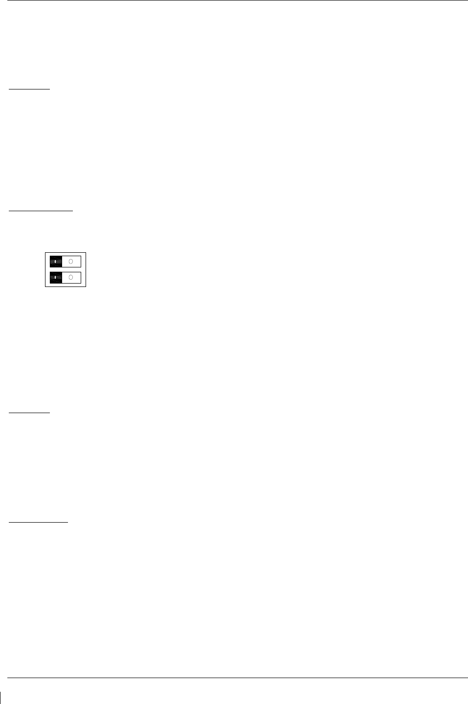
Page 6-16 G1000/GFC700 System Maintenance Manual – C90A/C90GT/C90GTi King Air
Revision G 190-00682-01
6.25 Standby Attitude Indicator
Ensure the standby attitude indicator gyro is not spinning—this may take 10 minutes or longer after the
unit has been turned off. This unit is very delicate; handle with care. Refer to the 4200 Series Attitude
Indicator Installation Manual, listed in Table 1-2, for more handling instructions.
Removal:
1. Remove MFD per Section 6.1.
2. Disconnect the electrical connector of the standby attitude indicator.
3. Use a 0.060” 6-Spline wrench to remove the knob from the front of the standby attitude indicator.
4. Use a Phillips screwdriver to remove the three attachment screws from the front of the standby
attitude indicator.
5.
Remove the standby attitude indicator
.
Reinstallation:
1. Ensure the lighting control voltage switches on rear of unit are set for 28V.
28V
2. Reinstallation of the standby attitude indicator is the reverse of the removal. Reference the Main
Instrument Panel Installation drawing, listed in Table 1-2, for more details.
3. If further maintenance is not required, proceed to Section 8.
6.26 Avionics Cooling Fans
Removal:
1. Gain access into the nose avionics equipment bay.
2. Disconnect the cooling fan hoses from the cooling fan.
3. Disconnect the electrical connector of the cooling fan.
4. Use a Phillips screwdriver to remove the three attachment screws from the cooling fan.
5.
Remove the cooling fan
.
Replacement:
1. Reinstallation of the avionics cooling fan is the reverse of the removal. Reference the Electrical
Equipment Install, Nose Bay drawing, listed in Table 1-2, for more details.
2. If further maintenance is not required, proceed to Section 8.

G1000/GFC700 System Maintenance Manual – C90A/C90GT/C90GTi King Air Page 6-17
190-00682-01 Revision G
6.27 GDU Cooling Fans
Removal:
1. Remove the display associated with the cooling fan, per Section
6.1
.
2. Disconnect the electrical connector of the cooling fan.
3. Use a Phillips screwdriver to remove the four attachment screws from the cooling fan.
4. Remove the cooling fan.
Replacement:
1. Reinstallation of the GDU cooling fan is the reverse of the removal. Reference the Main
Instrument Panel Installation drawing, listed in Table 1-2, for more details.
2.
If further maintenance is not required, proceed to Section 8.

Page 6-18 G1000/GFC700 System Maintenance Manual – C90A/C90GT/C90GTi King Air
Revision G 190-00682-01
This page intentionally left blank.

G1000/GFC700 System Maintenance Manual – C90A/C90GT/C90GTi King Air Page 7-1
190-00682-01 Revision G
7 G1000 Equipment Configuration & Testing
This section provides procedures to be followed after a piece of G1000 equipment is replaced. At the
beginning of each LRU section, instructions are given to guide the technician for various
removal/replacement scenarios. These instructions define necessary procedures to be followed for
situations where original equipment was reinstalled as well as for situations where new equipment (new
serial number) is installed.
CAUTION
Remove Supplemental Database Cards from the lower slot of all displays before loading
software into any unit. Not removing the cards may corrupt them. Replacing corrupted
database cards are not covered under warranty.
NOTE
Garmin recommends the use of SanDisk or Cactus brand SD cards to load G1000
software and configuration files. If another brand of card is used, and software loading
problems occur, replace the card with a SanDisk or Cactus brand card and reattempt the
software load.
WARNING
Connect a ground power unit to the aircraft for software loading. Do not rely on only the
aircraft batteries to prevent loss of power during the software loading process. DO NOT
ALLOW POWER TO BE REMOVED FROM THE SYSTEM WHEN LOADING
SOFTWARE! Remove power only when told to do so by the following procedure. As a
general rule all displays should be in the same mode (configuration or normal), unless
instructed differently.
7.1 GDU 1040/1500 MFD & PFD
Original Display Reinstalled
If the removed display(s) are re-installed in their original positions, no software or configuration loading
is required. This does not include units that were returned for repair as their software and configuration
files are deleted during the repair testing process. Continue to the PFD/MFD Test procedure.
Original PFD Displays Installed in Opposite Locations for Troubleshooting
If the PFD 1 and PFD 2 are installed in opposite positions, no software or configuration loading is
required. Continue to the PFD/MFD Test procedure.
New Repair or Exchange Display(s) Installed
If a new, repaired or exchange GDU 1040A or GDU 1500 is installed, the correct software and
configuration files must be loaded to the unit. See Section 3.9. If ChartView or TAWS were previously
installed, these must be reactivated. See Sections 3.9.6 and 3.9.7 respectively. If any other options were
previously installed, these must also be reactivated per Section 3.9.4. Then continue to the PFD/MFD
Test procedure.
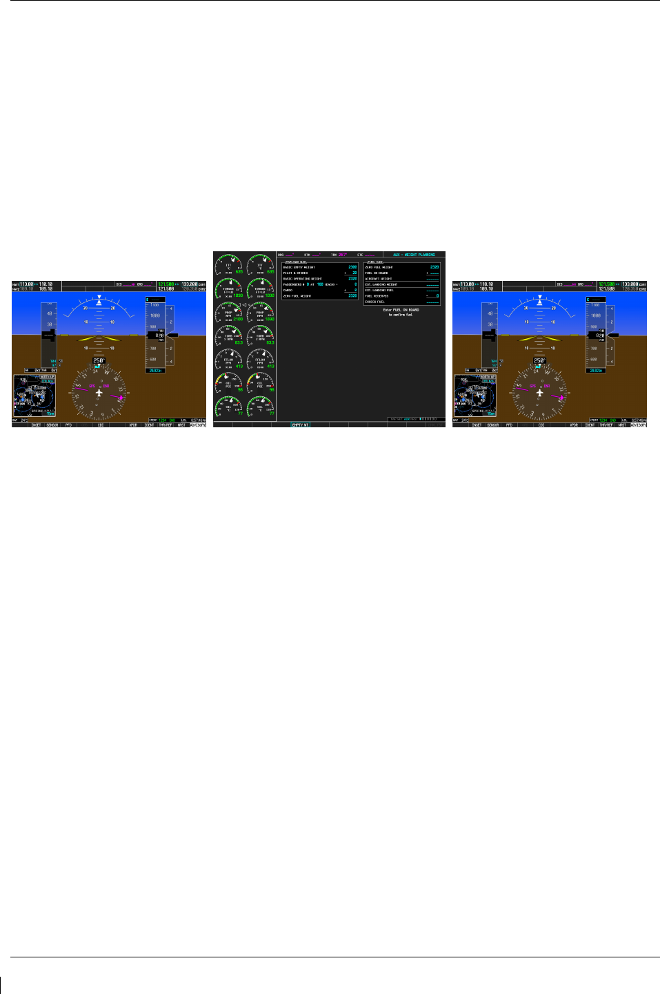
Page 7-2 G1000/GFC700 System Maintenance Manual – C90A/C90GT/C90GTi King Air
Revision G 190-00682-01
7.1.1
PFD/MFD Test
1. Allow displays to initialize for ~1 minute.
2.
Check that all COM/NAV display fields are valid in the top corners of both PFDs.
3. Check that attitude, heading, altitude, airspeed, vertical speed and OAT fields are valid within 2
minutes of power up on both PFDs.
4. Press the SENSOR softkey on each PFD and switch between ADC1 and ADC2. Verify that data
from both GDC 74Bs is valid on both displays.
5. Press the SENSOR softkey on each PFD and switch between AHRS1 and AHRS2. Verify that
data from both GRS 77s is valid on both displays.
6. Check that the engine instrument fields are valid on the MFD.
Figure 7-1. G1000 Normal Mode Check
7. Push the red DISPLAY BACKUP button on the pilot-side GMA 1347D. Verify that the pilot-
side PFD and MFD displays enter reversion mode. MFD should have valid altitude, airspeed,
vertical speed, COMM1, COMM2, NAV1, NAV2 and engine instruments.
8. De-activate pilot-side reversion mode by pushing the DISPLAY BACKUP button. Verify PFD 1
and MFD return to normal display modes.
9. Repeat Step 1 using GMA2. Ensure that PFD 2 and MFD enter reversion mode and MFD
displays valid altitude, airspeed, vertical speed, COMM1, COMM2, NAV1, NAV2 and engine
instruments.
10. De-activate co-pilot’s side reversion mode by pushing the DISPLAY BACKUP button. Verify
PFD 2 and MFD return to normal display modes.
11. If TAWS was activated, select the TAWS page (4th page in the MAP group) on the MFD.
a. Verify that the title at the top of the page reads “MAP – TAWS-B”. If TAWS has not been
enabled, the title will read “MAP – TERRAIN PROXIMITY” or “MAP – TERRAIN”.
b. Press the MENU button and select “Test TAWS” from the pop-up menu.
c. After the TAWS test has completed, verify that “TAWS System Test Okay” is heard over
the cockpit speaker.
12. If no other service is to be performed, perform final return-to-service test as specified in
Section 8.

G1000/GFC700 System Maintenance Manual – C90A/C90GT/C90GTi King Air Page 7-3
190-00682-01 Revision G
7.2 GMA 1347D Audio Panel
Original GMA 1347D Reinstalled
No software/configuration loading or testing is required if the removed GMA 1347D is re-installed. This
does not include units that were returned for repair as their software and configuration files are deleted
during the repair testing process. Continue to the final return-to-service checks in Section 8.
Original GMA 1347D Installed in Opposite Locations for Troubleshooting
If the original GMA #1 and GMA #2 are installed in opposite locations, configuration loading is required.
See Section 3.9, and then continue to the GMA 1347D Test (Section 7.2.1).
New Repaired or Exchange GMA 1347D Installed
If a new repaired or exchanged GMA 1347D is installed, the correct software and configuration files must
be loaded to the unit. See Section 3.9, and then continue to the GMA 1347D Test (Section 7.2.1).
7.2.1
GMA 1347D Test
Except for marker beacon operation, an in-aircraft checkout may be performed in the aircraft with known
good microphone, headset, and speaker.
7.2.1.1 Intercom System (ICS) Check for GMA 1347D, PN 011-01257-00.
NOTE
This procedure is applicable only to aircraft equipped with GMA 1347D Part Number 011-
01257-00. Reference Figure 3-6 for control button identification and location for the GMA
1347D, PN 011-01257-00.
1. Ensure that the MAN SQ key is off (no light).
2. Adjust GMA1 and GMA2 ICS volume to a comfortable level.
3. Plug in a headset at each COCKPIT ICS position. One at a time, plug a headset into each left and
right CABIN ICS jack location (one headset on right, one headset on left).
4. Verify the following:
• Two-way communication between each CABIN ICS jack position.
• CABIN ICS position cannot hear the pilot and copilot.
• CABIN ICS positions cannot be heard by the pilot or copilot.
5. On GMA1 select COM1 MIC and AUDIO.
6. Ensure INTR COM is deselected on GMA1 or GMA2. Verify an active (green) COM1 frequency
is displayed on both PFDs.
7. On GMA1 or 2 select PA and verify the PA select annunciator is illuminated on GMA1 and
GMA2. Verify COM1 active frequency is displayed white
8. Initiate passenger address using pilot’s headset boom mic by keying the pilot’s PTT. Verify the
following:
• Clear PA audio can be heard over cabin speaker and CABIN ICS headsets
• PA selected annunciator on GMA1 flashes ~ once per second during PA address.
9. Repeat Step 8 using pilot hand mic.
10. Initiate passenger address using copilot’s headset boom mic by keying the copilot’s PTT. Verify
the following:

Page 7-4 G1000/GFC700 System Maintenance Manual – C90A/C90GT/C90GTi King Air
Revision G 190-00682-01
• Clear PA audio can be heard over cabin speaker and CABIN ICS headsets
• PA selected annunciator on GMA1 flashes ~ once per second during PA address.
11. Repeat Step 10 using copilot hand mic.
7.2.1.2 Intercom System (ICS) Check for GMA 1347D, PN 011-01257-20.
NOTE
This procedure is applicable only to aircraft equipped with GMA 1347D Part Number 011-
01257-20. Reference Figure 3-7 for control button identification and location for the GMA
1347D, PN 011-01257-20.
1. Ensure that the MAN SQ key is off (no light).
2. Adjust GMA1 and GMA2 ICS volume to a comfortable level.
3. One at a time, plug a headset into each left and right CABIN ICS jack location (one headset on
right, one headset on left).
4. Verify the following:
• Two-way communication between each CABIN ICS jack position.
• CABIN ICS positions cannot be heard by the pilot or copilot.
5. Select GMA1 INTR COM button and verify the following:
• Passengers can communicate with each other.
• GMA2 INTR COM light is illuminated.
• The pilot and copilot can communicate with each other and cannot hear passengers.
6. Deselect INTR COM.
7. On GMA1 select CABIN button and verify the following:
• Passengers can communicate with each other.
• The pilot (copilot if GMA2 CABIN selected)
and passengers can all hear each other.
• On GMA1 deselect CABIN button.
8. Repeat step 7 using GMA2.
9. Select CABIN button on both GMAs and verify the following:
• Passengers can communicate with each other.
• The pilot and copilot can communicate with each other and the passengers.
10. Deselect the CABIN button on both GMAs.
11. On both GMAs select COM1 MIC and AUDIO.
12. Ensure INTR COM is deselected on GMA1 or GMA2. Verify an active (green) COM1 frequency
is displayed on both PFDs.
13. On GMA1, select PA and verify the PA select annunciator is illuminated on GMA1. Verify
COM1 active frequency is displayed white.

G1000/GFC700 System Maintenance Manual – C90A/C90GT/C90GTi King Air Page 7-5
190-00682-01 Revision G
14. On GMA 2, select PA and verify the PA select annunciator is illuminated on GMA2. Verify
COM1 active frequency is displayed white.
15. Initiate passenger address using pilot’s headset boom mic by keying the pilots PTT. Verify clear
PA audio can be heard over cabin speaker and passenger headsets, PA selected annunciator on
GMA1 flashes ~ once per second during PA address. Repeat using pilot hand mic.
16. Initiate passenger address using copilot’s headset boom mic by keying the copilots PTT. Verify
clear PA audio can be heard over cabin speaker and passenger headsets, PA selected annunciator
on GMA1 flashes ~ once per second during PA address. Repeat using copilot hand mic.
7.2.1.3 Transceiver Operational Check
Perform a ramp test radio check by exercising the installed transceivers, microphone, microphone key and
audio over the headphones and speaker. Verify that communications are clear and PTT operation is
correct for each pilot position.
1. On the pilot’s audio panel, select the audio source corresponding to each installed avionics unit (i.e.
NAV1, NAV2, COM1, COM2, ADF and DME) and check for audio over the pilot’s headset.
2. Press the SPKR key on the pilot’s audio panel and verify that the selected audio is heard over the
pilot’s speaker.
3. On the co-pilot’s audio panel, select the audio source corresponding to each installed avionics unit
(i.e. NAV1, NAV2, COM1, COM2, ADF and DME) and check for audio over the co-pilot’s headset.
4. Press the SPKR key on the co-pilot’s audio panel and verify that the selected audio is heard over the
co-pilot’s speaker.
7.2.1.4 Failsafe Operation Check – GMA 1347D #1
1. Turn the GMA 1347D #1 off by pulling the AUDIO NO 1 circuit breaker. This directs all COM 1
phone audio, MIC audio and MIC key to the pilot’s position.
2. Check the failsafe operation by exercising the COM 1 boom mic, hand mic, microphone key and
audio over the headphones. All volume control for the COM audio should be through the PFD
volume control. Verify proper operation of COM 1 using the failsafe operation.
3. Close the AUDIO NO 1 circuit breaker to continue testing.
7.2.1.5 Failsafe Operation Check – GMA 1347D #2
1. Turn the GMA 1347D #2 off by pulling the AUDIO NO 2 circuit breaker. This directs all COM 2
phone audio, MIC audio and MIC key to the co-pilot’s position.
2. Check the failsafe operation by exercising the COM 2 boom mic, hand mic, microphone key and
audio over the headphones. All volume control for the COM audio should be through the PFD
volume control. Verify proper operation of COM 2 using the failsafe operation.
3. Close the AUDIO NO 2 circuit breaker to continue testing.

Page 7-6 G1000/GFC700 System Maintenance Manual – C90A/C90GT/C90GTi King Air
Revision G 190-00682-01
7.2.1.6 Marker Beacon Test
Figure 7-2. Marker Beacon Symbology
1. Using a ramp tester, simulate the outer marker, middle marker and inner marker signals by following
the test equipment manufacturer’s instructions. Verify that each marker audio signal is present over
the pilot and co-pilot headphones and speaker.
2. Verify that the outer, middle, and inner annunciations appear on PFD 1 and PFD 2 when the
corresponding signal is applied. Marker beacon annunciations appear at the upper left corner of the
altitude indicator on the PFD (Figure 7-2). Operate the MKR MUTE key on the #1 and #2 GMA
1347D and ensure that the audio signal is muted.
3. If no other service is to be performed, continue to the return-to-service checks in Section 8.

G1000/GFC700 System Maintenance Manual – C90A/C90GT/C90GTi King Air Page 7-7
190-00682-01 Revision G
7.2.2
Landing Gear Aural Alert Check
This check should be conducted in conjunction with the Phase 2 and Phase 4 Landing Gear Retraction,
Warning Horn check, in the existing King Air Maintenance Program.
NOTE
This procedure is applicable only to aircraft equipped with a tone generator as part of the
aircraft audio system. Refer to the appropriate aircraft wiring diagrams to determine if a
tone generator is installed.
This check can be accomplished in conjunction with the Weight on Wheels and Low
Speed Awareness Band Test in Section 7.22.
1. Conduct the Landing Gear Retraction, Warning Horn check as stated in the King Air Model C90
Series Maintenance Manual, listed in Table 1-2.
2. Verify that the aural tone is played through the G1000 audio system and through both cockpit
speakers.
7.2.3
XM Audio Suppression Check for Aircraft with a Tone Generator
NOTE
This procedure is applicable only to aircraft equipped with a tone generator as part of the
aircraft audio system. Refer to the appropriate aircraft wiring diagrams to determine if a
tone generator is installed.
This procedure is applicable only to aircraft that have XM radio subscriptions.
1. Select the AUX – XM RADIO page on the MFD.
2. Plug a set of headphones into the pilot and co-pilot stations and verify that you can hear the XM radio
playing in both channels.
3. Restart PFD1 in configuration mode.
4. Select page 4, Audio Alert Configuration, from the Systems menu by rotating the small FMS knob.
5. Select PLAY for the following audio and verify XM audio is temporarily muted while alert audio is
being played.
• GEAR
• STALL
6. Verify XM audio is temporarily muted in both pilot and co-pilot stations while alert audio is being
played.
7. Restart PFD1 in normal mode.

Page 7-8 G1000/GFC700 System Maintenance Manual – C90A/C90GT/C90GTi King Air
Revision G 190-00682-01
WARNING
The following step requires moving the stall warning vane. Use caution when
handling the stall warning vane.
8. While monitoring pilot and copilot XM audio, actuate the stall warn transducer on the left wing
leading edge in an up position (for those aircraft equipped with a Safeflight computer, actuate in the
aft position), verify the following:
• Stall warning tone is active.
•
Pilot and copilot XM audio is muted.
9. Release the stall warning transducer in the left wing leading edge, verify the following:
• Stall warning tone is silenced.
10. Verify XM audio returns.
7.2.4
XM Audio Suppression Check for Aircraft Without a Tone Generator
GDL69A discrete inputs from stall warning and landing gear control systems as detailed in 005-W0022-
00 “Wiring Diagram, G1000 / GFC 700 King Air C90A/C90GT” are required for aircraft not equipped
with a tone generator.
NOTE
This procedure is applicable only to aircraft equipped without a tone generator as part of
the aircraft audio system. Refer to the appropriate aircraft wiring diagrams to determine if
a tone generator is installed.
WARNING
The following procedure requires operation of the aircraft landing gear. Observe
all applicable safety precautions. Before working in any landing gear wheel well,
ensure that all landing gear and gear door safety devices are installed. Exercise
extreme caution while working around landing gear or in landing gear wheel wells.
Gear warning discrete
1. Reference the King Air C90 Maintenance Manual listed in Table 1-2 and jack aircraft to allow
operation of landing gear.
2. Select the AUX – XM RADIO page on the MFD.
3. Plug a set of headphones into the pilot and co-pilot stations and verify that you can hear the XM radio
playing in both channels. Adjust volume to a comfortable level.
4. Ensure both left and right throttles are at IDLE position.
5. Retract landing gear to the full up and locked position.
6. Verify the landing gear warning horn is active.
7. Verify XM audio is muted in the pilot and co-pilot stations.
8. Increase both left and right throttles forward of IDLE position (towards takeoff position).
9. Verify landing gear warning horn is silenced and XM audio remains muted.
10. On the MFD deselect mute softkey or adjust XM volume. Verify XM audio returns.
11. Extend landing gear to the full down and locked position and return both throttles to idle position.
12. Aircraft may be removed from jacks to accommodate other activities as required.

G1000/GFC700 System Maintenance Manual – C90A/C90GT/C90GTi King Air Page 7-9
190-00682-01 Revision G
Stall warning discrete
1. Select the AUX – XM RADIO page on the MFD.
2. Plug a set of headphones into the pilot and co-pilot stations and verify that you can hear the XM radio
playing in both channels.
3. Ensure STALL WARNING circuit breaker is closed.
4. While monitoring pilot and copilot XM audio, actuate the stall warn transducer on the left wing
leading edge in an up position, verify the following:
WARNING
The stall warning transducer is heated at all times;use of a heavy glove is
recommended to prevent a burn.
• Stall warning tone is active and annunciation is illuminated.
•
Pilot and copilot XM audio is muted.
5. Release the stall warning transducer in the left wing leading edge, verify the following:
• Stall warning tone is silenced and annunciation extinguishes.
•
Pilot and copilot XM audio remains muted.
6. On the MFD deselect mute softkey or adjust XM volume. Verify XM audio returns.
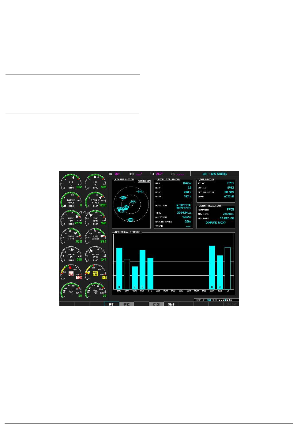
Page 7-10 G1000/GFC700 System Maintenance Manual – C90A/C90GT/C90GTi King Air
Revision G 190-00682-01
7.3 GIA 63W Integrated Avionics Unit
Original GIA 63W(s) Reinstalled
No software or configuration loading is required if the removed GIA is re-installed in its original position
(GIA1 and GIA2 in their original racks). This does not include units that were returned for repair as their
software and configuration files are deleted during the repair testing process. Continue to the return-to-
service checks in Section 8.
Original GIA 63Ws Swapped for Troubleshooting
No software loading is required if the originally installed GIA units are re-installed in opposite positions
(GIA1 and GIA2 in opposite unit racks). However, configuration loading is required. See Section 3.9,
and then continue to the GIA 63W Test (Section 7.3.1).
New Repaired or Exchange GIA 63W(s) Installed
If a new repaired or exchange GIA 63W is installed, the correct software and configuration files must be
loaded to the unit. See Section 3.9, and then continue to the GIA 63W Test (Section 7.3.1).
7.3.1
GIA 63W Test
GPS Signal Acquisition
Figure 7-3. AUX – GPS STATUS Page (MFD)
The GIA 63W units should normally acquire a GPS navigation solution within 5 to 10 minutes of startup,
provided the aircraft is outside (or indoors with a GPS repeater). Select the GPS STATUS page on the
MFD (4th page in AUX group). Two softkeys on the bottom of the display allow the user to toggle
between GPS 1 and GPS 2. Verify that both receivers show 3D DIFF NAV on the MFD.
Continue to the VHF COM Interference test.
NOTE
It may be necessary to temporarily disable or move away from GPS repeaters while
testing, as repeaters may adversely affect GPS receiver performance.

G1000/GFC700 System Maintenance Manual – C90A/C90GT/C90GTi King Air Page 7-11
190-00682-01 Revision G
VHF COM Interference Test
This test must be conducted outside. Use of a GPS repeater inside a hangar may result in a failed test.
This procedure assumes that the system is currently set to 25 kHz COM channel spacing. Once the signal
acquisition test has been completed successfully, perform the following steps:
1. On the MFD, monitor GPS signal strength bars on the AUX – GPS STATUS page.
2. On the PFD, ensure that the CDI is set to GPS. If it is not, press the ‘CDI’ softkey until GPS ENR is
displayed.
3. Verify that the GPS “INTEG” flag is out of view.
4. Select 121.150 MHz on the No. 1 COM transceiver.
5. Transmit for a period of 35 seconds while monitoring GPS 1 signal strength levels.
6. During the transmit period, verify that the GPS “INTEG” flag does not come into view on the PFD
and verify that GPS 1 does not lose a 3-D navigation solution on the MFD.
7. Repeat steps 5 and 6 and re-transmit while monitoring GPS 2 signal levels on the MFD.
8. Repeat steps 4 through 7 for each of the following frequencies:
•
121.175 MHz
•
121.200 MHz
•
131.250 MHz
•
131.275 MHz
•
131.300 MHz
9. Repeat steps 4 through 8 for the No. 2 COM transceiver (GIA2).
10. On the MFD, select the AUX – SYSTEM SETUP page.
11. Under the COM CONFIG field, change the COM channel spacing from 25 kHz to 8.33 kHz.
12. Go back to the AUX – GPS STATUS page.
13. Select 121.185 MHz on the No. 1 COM transceiver.
14. Transmit for a period of 35 seconds while monitoring GPS 1 signal strength levels.
15. During the transmit period, verify that the GPS “INTEG” flag does not come into view on the PFD
and verify that GPS 1 does not lose a 3-D navigation solution on the MFD.
16. Repeat steps 14 and 15 and re-transmit while monitoring GPS 2 signal levels on the MFD.
17. Repeat steps 14 through 16 for each of the following frequencies:
•
121.190 MHz
•
130.285 MHz
•
131.290 Mhz
18. Repeat steps 14 through 17 for the No. 2 COM transceiver (GIA2).
19. On the MFD, select the AUX – SYSTEM SETUP page and change the COM channel spacing back to
25 kHz.
20. Continue to the VOR/LOC/GS Test.

Page 7-12 G1000/GFC700 System Maintenance Manual – C90A/C90GT/C90GTi King Air
Revision G 190-00682-01
VOR/LOC/GS Test
Check the VOR, ILS, and Glideslope functions with ramp test equipment. Operate the equipment
according to the test equipment manufacturer’s instructions. Adjust the RF signal to a level adequate to
perform the test. Select the appropriate HSI source by using the CDI softkey.
NOTE
The PFD HSI does not show a course deviation bar unless a valid VHF NAV frequency
is tuned.
GFC 700 VOR/LOC/GS Test
1. Ensure FD is coupled to PFD1 as indicated by a left pointing arrow next to the AFCS mode controller
XFR button.
2. Simulate a VOR signal on a radial equivalent to the aircraft heading. Tune the NAV 1 and NAV 2
receivers to the simulation frequency.
3. Set the HSI on PFD1 to VOR1 by pressing the CDI soft key until VOR1 is selected. Set the HSI on
PFD2 to VOR2 by pressing the CDI soft key until VOR2 is selected. Rotate CRS1 and CRS2 knobs
to set VOR1 and VOR2 course pointers to aircraft heading. (CDI Synchronization must be set to
OFF on the AUX-SYSTEM SETUP 1 page on the MFD.)
4. Verify full scale deflection of VOR1 and VOR2 CDI by varying CRS1 and CRS2 selected course at
least 10° left and right. Reset course pointers to aircraft heading.
5. Engage the autopilot and press the NAV key on the AFCS mode controller. Using the CRS1 knob
alter course by 10° to the right. Verify the flight director and aircraft controls respond by flying to the
VOR course. Repeat to the left.
6. Couple FD to PFD2 by pressing the XFR button on the AFCS mode controller. Verify FD is coupled
right as indicate by a right pointing arrow on the AFCS mode controller next to the XFR button.
Repeat step 5 using CRS2 knob while coupled to PFD2.
7. Set CRS1 and CRS2 course pointers to aircraft heading.
8. Simulate a Localizer/Glideslope signal. Tune this signal on NAV 1 and NAV 2 receiver. Set the
PFD1 HSI to LOC1 and PFD2 HSI to LOC2 by pressing CDI soft key until LOC1 and LOC2 is
selected. Use the test equipment to center the deviation bars (localizer and glideslope) on PFD1 and
PFD2.
9. Press the APR key on the AFCS mode controller. Verify that the LOC and PIT annunciations are
green and ALTS and GS are white on PFD1 and PFD2. Apply right/left and up/down
localizer/glideslope signals using the test equipment. Verify that the Flight Director and flight
controls respond appropriately.
10. Couple FD to PFD1 by pressing the XFR button on the AFCS mode controller. Verify FD is coupled
to PFD1 as indicate by a left pointing arrow on the AFCS mode controller next to the XFR button.
11. Repeat step 9 using while coupled to PFD1.
12. If no other service is to be performed, continue to the return-to-service checks in Section 8.
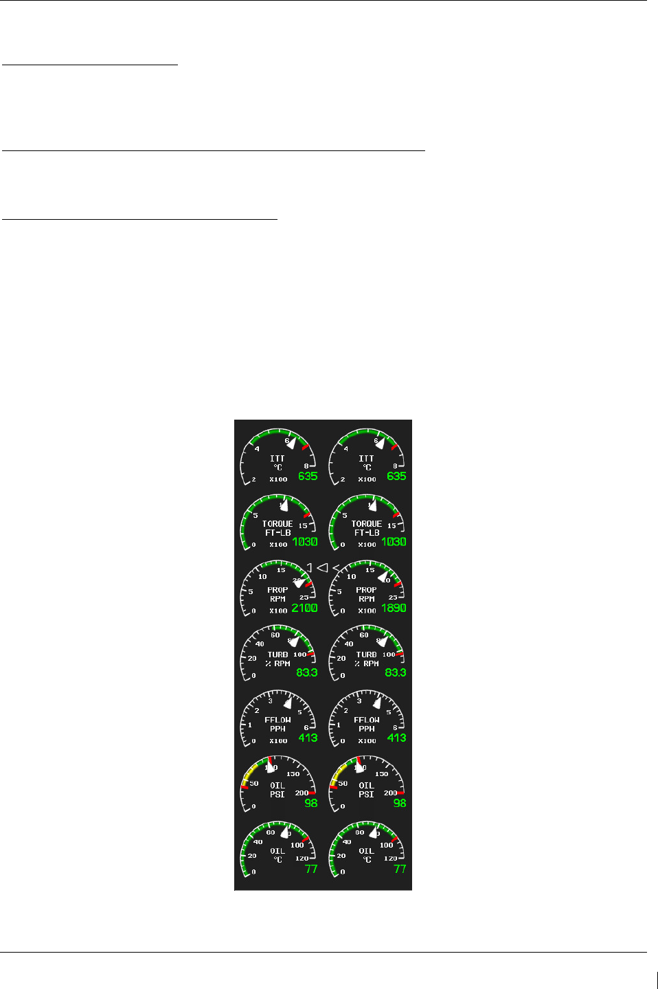
G1000/GFC700 System Maintenance Manual – C90A/C90GT/C90GTi King Air Page 7-13
190-00682-01 Revision G
7.4 GEA 71 Engine/Airframe Unit
Original GEA 71 Reinstalled
No software or configuration loading is required if the removed GEA 71 is re-installed. This does not
include units that were returned for repair as their software and configuration files are deleted during the
repair testing process. Continue to the return-to-service checks in Section 8.
Original GEA 71 Installed in Opposite Locations for Troubleshooting
No software loading is required if the original GEA units are installed in opposite locations (GEA #1 and
GEA #2 in opposite unit racks). Continue to the GEA 71 Test (Section 7.4.1).
New Repaired or Exchange GEA 71 Installed
If a new repaired or exchange GEA 71 is installed, the correct software and configuration files must be
loaded to the unit. See Section 3.9, and then continue to the GEA 71 Test (Section 7.4.1).
7.4.1
GEA 71 Test
On the MFD (normal mode), check the indication for each of the sensor or monitor inputs with the
aircraft engines off.
In general, verify all engine and system instruments show valid static normal values and markings, with
no red Xs or erratic indications. Reference figure below for normal engine instrument markings (baseline
configuration instruments shown, may not reflect actual aircraft configuration). If necessary, reference
Section 7.4.2 for additional tests to verify instrument readings.
Figure 7-4. Normal Engine Instrument Markings (MFD)
If no other service is to be performed, continue to the return-to-service checks in Section 8.
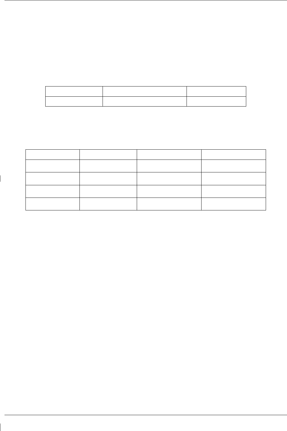
Page 7-14 G1000/GFC700 System Maintenance Manual – C90A/C90GT/C90GTi King Air
Revision G 190-00682-01
7.4.2
Additional GEA 71 Functional Tests
This section provides additional functional tests for individual GEA parameters.
7.4.2.1
Torque Functional Test
Required test equipment:
Test Equipment Make/Requirement Model/Part Nbr
Signal Generator 0-10Vdc / 0 – 1k Hz As appropriate
1. Using a signal generator, inject a DC signal into the No. 1 GEA via left engine firewall connectors-
pins J102-C (HI) and J102-R (LO).
2. Simulate the following voltages, and verify the indication and status:
Test Point (Vdc) Indication (ft-lbs) Status Configurations
0.00 +/- .02
0
bottom of green band
Green digital all
2.53 +/- .02 1320
red digital*
NOTE: red radial 1315 4-10, 21-22
2.90 +/- .02 1525
red digital*
NOTE: red radial 1520 1-3, 14-20
3.15 +/- .02
1655
red digital*
NOTE: red radial 1650 11-13
(*) steady after 5 seconds
3. On the right hand circuit breaker panel, open the GIA1 (PRI) and GIA1 (SEC) circuit breakers, and
verify the last observed torque indication remains unchanged.
4. Close the GIA1 (PRI) and GIA1 (SEC) circuit breakers, and wait until the COM1 and NAV1 fields
are valid.
5. Repeat steps 1 and 2 using the No. 2 GEA via right engine firewall connectors-pins J103-C (HI)
and J103-R (LO).
6. Pull the GIA 2 circuit breaker, and verify the last observed torque indication remains unchanged.
7. Close the GIA 2 circuit breaker, and wait until the COM2 and NAV2 field are valid.
8. If no other tests will be completed in this section, do the following:
a. Disconnect test equipment.
b. Ensure firewall connectors are reconnected.
c. Verify all engine parameters are displayed valid on the MFD with no Red X’s.

G1000/GFC700 System Maintenance Manual – C90A/C90GT/C90GTi King Air Page 7-15
190-00682-01 Revision G
7.4.2.2
ITT Functional Test
Required test equipment:
Test Equipment Make/Requirement Model/Part Nbr
Signal Generator 0-10Vdc / 0 – 1k Hz As appropriate
1. Remove left engine ITT thermocouple terminals from sensor. Using a signal generator, inject a DC
signal into the No. 1 GEA via left engine firewall connectors-pins, as follows:
S/N LJ-1063 thru LJ-1360, LJ-1362: J104-T* (LO) and J104-W* (HI)
S/N LJ-1361, LJ-1363 and after: J104-P* (LO) and J104-S* (HI)
2. Simulate the following voltages, and verify the indication and status:
Test Point (mV) Indication (degC) Status Configurations
16.40 +/- .28
400*
bottom of green band
green digital all
44.3 +/- .28 1090*
red triangle, start mode
red digital** all
(*) verify value displayed is within test point tolerances
(**) steady after 5 seconds
3. On the right hand circuit breaker panel, open the GIA1 (PRI) and GIA1 (SEC) circuit breakers, and
verify the last observed ITT indication remains unchanged.
4. Close the GIA1 (PRI) and GIA1 (SEC) circuit breakers, and wait until the COM1 and NAV1 fields
are valid.
5. Repeat steps 1 and 2 using the No. 2 GEA via right engine firewall connectors-pins specified below
and right engine ITT thermocouple.
S/N LJ-1063 thru LJ-1360, LJ-1362: J105-T* (LO) and J105-W* (HI)
S/N LJ-1361, LJ-1363 and after: J105-P* (LO) and J105-S* (HI)
6. Pull the GIA 2 circuit breaker, and verify the last observed ITT indication remains unchanged.
7. Close the GIA 2 circuit breaker, and wait until the COM2 and NAV2 field are valid.
8. If no other tests will be completed in this section, do the following:
a. Disconnect test equipment.
b. Ensure firewall connectors are reconnected.
c. Verify all engine parameters are displayed valid on the MFD with no Red X’s.
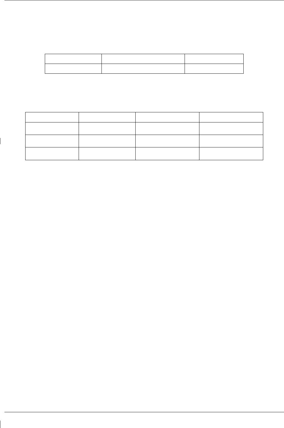
Page 7-16 G1000/GFC700 System Maintenance Manual – C90A/C90GT/C90GTi King Air
Revision G 190-00682-01
7.4.2.3
Oil Pressure Functional Test
Required test equipment:
Test Equipment Make/Requirement Model/Part Nbr
Signal Generator 0-10Vdc / 0 – 1k Hz As appropriate
1. Using a signal generator, inject a DC signal into the No. 1 GEA via left engine firewall connectors-
pins J104-A (LO) and J104-B (HI).
2. Simulate the following voltages, and verify the indication and status:
Test Point (Vdc) Indication (PSI) Status Configurations
.98 +/- .1
39 +/- 1
red digital
NOTE: low red radial 40 all
2.0 +/- .1 80 +/- 1
bottom of green band
Green digital 4-10, 21-22
2.1 +/- .1 85 +/- 1
bottom of green band
Green digital 1-3, 11-20
3. On the right hand circuit breaker panel, open the GIA1 (PRI) and GIA1 (SEC) circuit breakers, and
verify the last observed oil pressure indication remains unchanged.
4. Close the GIA1 (PRI) and GIA1 (SEC) circuit breakers, and wait until the COM1 and NAV1 fields
are valid.
5. Repeat steps 1 and 2 using the No. 2 GEA via right engine firewall connectors-pins J105-A (LO)
and J105-B (HI).
6. Pull the GIA 2 circuit breaker, and verify the last observed oil pressure indication remains
unchanged.
7. Close the GIA 2 circuit breaker, and wait until the COM2 and NAV2 field are valid.
8. If no other tests will be completed in this section, do the following:
a. Disconnect test equipment.
b. Ensure firewall connectors are reconnected.
c. Verify all engine parameters are displayed valid on the MFD with no Red X’s.
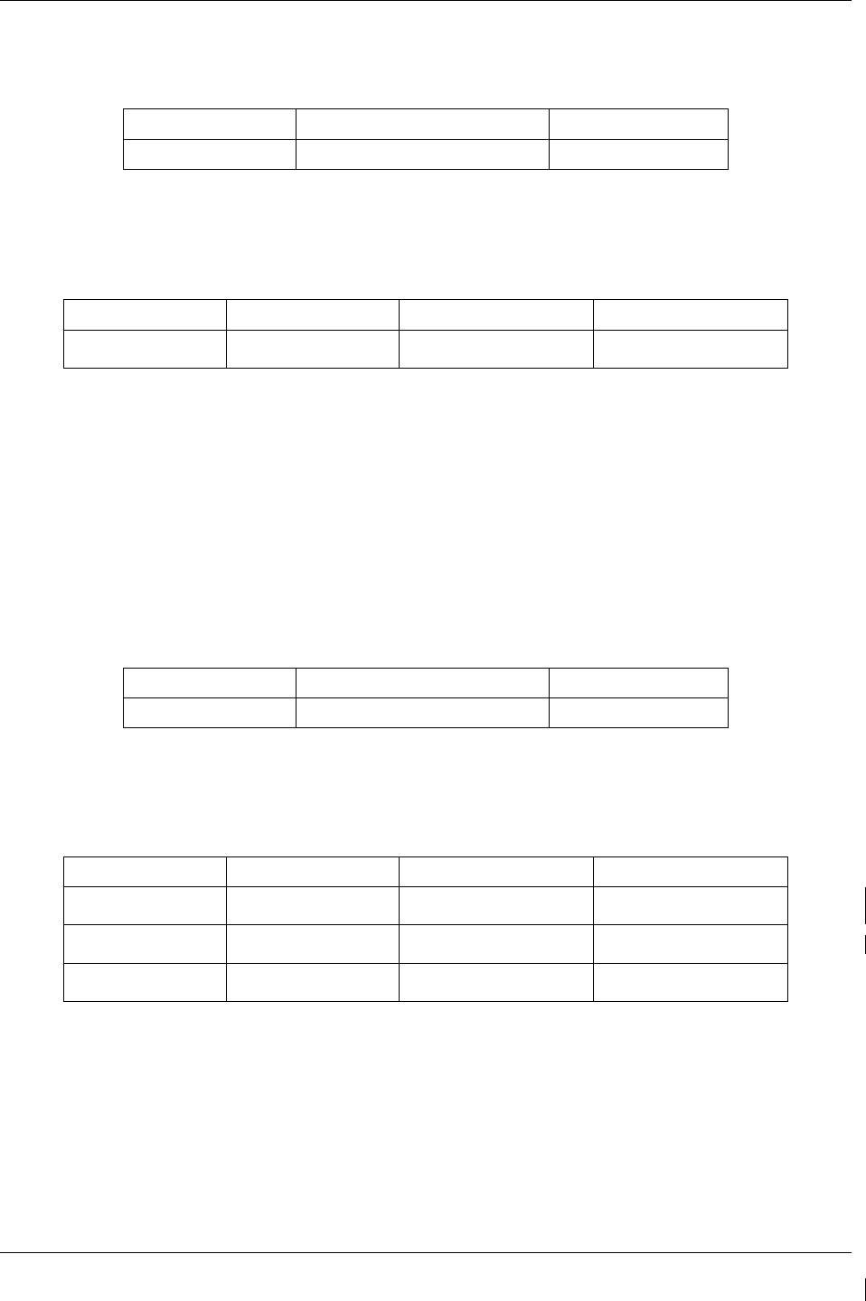
G1000/GFC700 System Maintenance Manual – C90A/C90GT/C90GTi King Air Page 7-17
190-00682-01 Revision G
7.4.2.4
Oil Temperature Functional Test
Required test equipment:
Test Equipment Make/Requirement Model/Part Nbr
Decade Box 0-1k ohms As appropriate
1. Using a decade box or equivalent, simulate resistance values into No. 1 GEA via left engine
firewall connectors-pins J104-W (HI) and J104-X (LO).
2. Simulate the following resistances, and verify the indication and status:
Test Point (ohms) Indication (DegC) Status Configurations
129 +/- 10 100
red digital*
NOTE: red radial 99 all
(*) steady after 5 seconds
3. Repeat steps 18 and 19 using the No. 2 GEA via right engine firewall connectors-pins J105-W (HI)
and J105-X (LO).
4. If no other tests will be completed in this section, do the following:
a. Disconnect test equipment.
b. Ensure firewall connectors are reconnected.
Verify all engine parameters are displayed valid on the MFD with no Red X’s.
7.4.2.5
Turbine Tach (N1) Functional Test
Required test equipment:
Test Equipment Make/Requirement Model/Part Nbr
Signal Generator 0-10Vdc / 0 – 1k Hz As appropriate
1. Using a signal generator, inject a 3 Vrms signal into the No. 1 TACH-GEN Adapter via left engine
firewall connectors-pins J104-J and J104-K.
2. Simulate the following frequencies, and verify the indication and status:
Test Point (Hz) Indication (%) Status Configurations
35.7 +/- .35 51
bottom of green band
green digital 4-6, 9, 21-22
40.6 +/- .35
58
bottom of green band
green digital 1-3, 7-8, 10-20
71.4 +/- .35
102
red digital*
NOTE: red radial 101.5 all
(*) steady after 5 seconds
3. Repeat steps 1 and 2 using the No. 2 TACH-GEN Adapter via right engine firewall connectors-pins
J105-J and J105-K.
4. If no other tests will be completed in this section, do the following:
a. Disconnect test equipment.
b. Ensure firewall connectors are reconnected.
c. Verify all engine parameters are displayed valid on the MFD with no Red X’s.
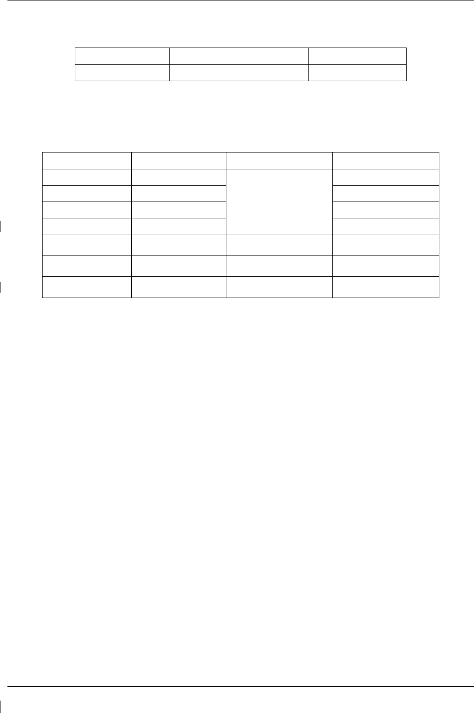
Page 7-18 G1000/GFC700 System Maintenance Manual – C90A/C90GT/C90GTi King Air
Revision G 190-00682-01
7.4.2.6
Prop Tach (N2) Functional Test
Required test equipment:
Test Equipment Make/Requirement Model/Part Nbr
Signal Generator 0-10Vdc / 0 – 1k Hz As appropriate
1. Using a signal generator, inject a 2.5 Vrms signal into the No. 1 TACH-GEN Adapter via left
engine firewall connectors-pins J102-W and J102-X.
2. Simulate the following frequencies, and verify the indication and status:
Test Point (Hz) Indication (rpm) Status Configurations
35.1 +/- .4
1100
bottom of green band
Green digital
9-10, 13, 16-18
47.9 +/- .4 1500
19
51.1 +/- .4 1600
1-8, 11-12, 14-15, 20
57.5 +/- .4 1800
21-22
57.5 +/- .4 1800
red digital*
NOTE: red radial 1750 11-13
62.3 +/- .4 1950
red digital*
NOTE: red radial 1900 1-3, 14-19
71.8 +/- .4
2250
red digital*
NOTE: red radial 2200 4-10, 20-22
(*) steady after 5 seconds
3. Repeat steps 1 and 2 using the No. 2 TACH-GEN Adapter via right engine firewall connectors-pins
J103-W and J103-X.
4. If no other tests will be completed in this section, do the following:
a. Disconnect test equipment.
b. Ensure firewall connectors are reconnected.
c. Verify all engine parameters are displayed valid on the MFD with no Red X’s.
G1000/GFC700 System Maintenance Manual – C90A/C90GT/C90GTi King Air Page 7-19
190-00682-01 Revision G
7.4.2.7
Fuel Flow Functional Test
Required test equipment:
Test Equipment Make/Requirement Model/Part Nbr
Decade Box 0-1k ohms As appropriate
Signal Generator 0-10Vdc / 0 – 1k Hz As appropriate
1. S/N LJ-1283 and after only: using a decade box or equivalent, simulate 1000 ohms into left engine
signal conditioner via left engine firewall connectors-pins J104-E and J104-F.
2. Using a signal generator, inject a 100 mV RMS / 0Hz signal into the left engine signal conditioner
via left engine firewall connectors-pins, as follows:
S/N LJ-1063 thru LJ-1282: J104-F and J104-E
S/N LJ-1283 and after: J104-V and J104-U
3. Simulate the following frequency, and verify the indication and status:
Test Point (Hz) Indication (pph) Status Configurations
140
100 +/- 10
green digital all
4. S/N LJ-1283 and after only: using a decade box or equivalent, simulate 1000 ohms into right engine
signal conditioner unit via right engine firewall connectors-pins J105-E and J105-F.
5. Repeat steps 2 and 3 using the right engine PC-920 via right engine firewall connectors-pins, as
follows:
S/N LJ-1063 thru LJ-1282: J105-F and J105-E
S/N LJ-1283 and after: J105-V and J105-U
6. If no other tests will be completed in this section, do the following:
a. Disconnect test equipment.
b. Ensure firewall connectors are reconnected.
c. Verify all engine parameters are displayed valid on the MFD with no Red X’s.
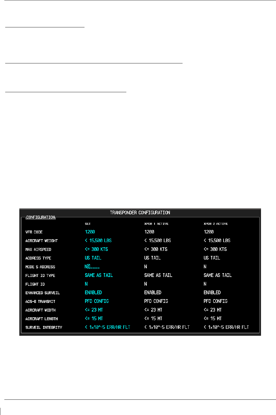
Page 7-20 G1000/GFC700 System Maintenance Manual – C90A/C90GT/C90GTi King Air
Revision G 190-00682-01
7.5 GTX 33 Transponder
Original GTX 33 is Reinstalled
No software or configuration loading is required if the removed GTX 33 is re-installed. This does not
include units that were returned for repair as their software and configuration files are deleted during the
repair testing process. Continue to GTX 33 Test (Section 7.5.2).
Original GTX 33 Installed in Opposite Locations for Troubleshooting
No software loading is required if the original GTX #1 and GTX #2 are installed in opposite locations.
Continue to Transponder Configuration (Section 7.5.1).
New Repaired or Exchange GTX 33 is Installed
If a new repaired or exchange GTX 33 is installed, the correct software and configuration files must be
loaded to the unit. See Section 3.9. Also enter the aircraft registration number in the GTX Config page
after loading software and configuration files. Then continue to Transponder Configuration (Section
7.5.1).
7.5.1
Transponder Configuration
1. If not applied, apply power to the G1000 system.
2. With PFD1 in configuration mode, select the GTX page group, then select the TRANSPONDER
CONFIGURATION page on PFD1.
3. The ‘ADDRESS TYPE’ default is ‘US TAIL’. To enter a non-US Mode-S registration number set
the ‘ADDRESS TYPE’ field to ‘HEX ID’.
4. Activate the cursor and highlight the ‘MODE S ADDRESS’ field. Use the small/large FMS knobs
to enter the US aircraft registration number or other Mode-S registration number.
Figure 7-5, Aircraft Registration
5. For US registered aircraft, the ‘FLIGHT ID TYPE’ field should be set to ‘SAME AS TAIL’. For
other aircraft, the ‘FLIGHT ID TYPE’ field should be set to ‘CONFIG ENTRY’ or ‘PFD ENTRY’.
NOTE

G1000/GFC700 System Maintenance Manual – C90A/C90GT/C90GTi King Air Page 7-21
190-00682-01 Revision G
The CONFIG ENTRY setting requires the Aircraft Registration/ID number to be entered
once in the ‘FLIGHT ID’ field. The PFD ENTRY setting allows the pilot to enter the
Aircraft Registration/ID number from the PFD, via the ‘TMR/REF’ softkey.
6. After each configuration setting change, press the ENT key to configure the transponders.
7. Press the ENT key on PFD1 to acknowledge prompt.
8. After completing transponder configuration, deactivate the cursor.
7.5.2
GTX 33 Test
Operation of the GTX 33 Mode-S transponder is accomplished using PFD 1, PFD 2 or the MFD. Refer to
G1000 in King Air C90 Cockpit Reference Guide, listed in Table 1-2, for basic operation.
The integrated transponder/altitude reporting system must be verified in accordance with Title 14 of the
Code of Federal Regulations (CFR) §§ 91.411 and 91.413, every 24 calendar months, or any time the
transponder is removed. This test requires the use of a Mode S ramp generator. Specific instructions for
operating the ramp tester are contained in the applicable operator's manual. Refer to Title 14 CFR Part 43
Appendix F for testing criteria.
If no other service is to be performed, continue to the return-to-service checks in Section 8.

Page 7-22 G1000/GFC700 System Maintenance Manual – C90A/C90GT/C90GTi King Air
Revision G 190-00682-01
7.6 GDC 74B Air Data Computer
Original GDC 74B is Reinstalled
No software or configuration loading is required if the removed GDC 74B is re-installed. This does not
include units that were returned for repair as their software and configuration files are deleted during the
repair testing process. Continue to GDC 74B Test (Section 7.6.1).
Original GDC 74B Installed in Opposite Locations for Troubleshooting
No software loading is required if the original GDC #1 and GDC #2 are installed in opposite locations.
Continue to GDC 74B Test (Section 7.6.1).
New Repaired or Exchange GDC 74B is Installed
If a new repaired or exchange GDC 74B is installed, the correct software and configuration files must be
loaded to the unit. See Section 3.9, and then continue to GDC 74B Test (Section 7.6.1).
New GDC 74B Configuration Module is Installed
The correct configuration files must be loaded if the GDC 74B configuration module has been replaced.
See Section 3.9, and then continue to GDC 74B Test (Section 7.6.1).
7.6.1
Air Data Test (GDC 74B and STBY Instruments)
The G1000 system must be maintained in accordance with the G1000 System Maintenance Manual listed
in Table 1-3 and appropriate regulations. When the GDC 74B is tested in accordance with 14 CFR Part
43, Appendix E, note the following exceptions:
• For paragraph (b)(1)(i) Scale Error, use Table 7-1 of this section instead of Appendix E, Table I
• Do not perform paragraph (b)(1)(iv) Friction
• Do not perform paragraph (b)(1)(vi) Barometric Scale Error
The following Air Data Test is to be performed in addition to or in conjunction with any other regulatory
required testing. This test must be performed on both pilot and copilot systems with a calibrated Air Data
Test Set (ADTS) with a combined accuracy/repeatability specification of less than ±20 feet for the test
altitude range. NOTE: Allow both GDC 74B units to stabilize for 15 minutes while powered before
conducting the following tests.
1. Perform pitot static system leak check of each system as specified below. Reference King Air 90
Series Maintenance Manual, 34-00-00.
a. With the pitot-static test set connected to the aircraft, perform a leak test of the aircraft pitot
plumbing at an altitude of 30,000 ft and airspeed of 226 knots. When pitot pressure has
stabilized, verify the cumulative leak rate is 1 knot/minute or less.
b. With the pitot-static test set connected to the aircraft, perform a leak test of the aircraft static
plumbing at an altitude of 30,000 feet and an airspeed of 120 knots. When static pressure has
stabilized, verify the cumulative leak rate is 200 ft/minute or less.
2. Connect the pitot/static tester to the aircraft left and right pitot and static ports. Note that the
standby altimeter and airspeed indicator are connected to the copilot side pitot and static lines.
3. Verify that the PFD1 altimeter baro setting is set to 29.92 in Hg (1013.25 mb).
4. Start PFD1 in configuration mode and navigate to the GRS page. The values for altitude and
airspeed are shown on the AHRS/AIR DATA INPUT table as B ALT and IAS for both
AIR DATA 1 and AIR DATA 2.

G1000/GFC700 System Maintenance Manual – C90A/C90GT/C90GTi King Air Page 7-23
190-00682-01 Revision G
5. Simulate the altitudes and airspeeds for each condition shown in Table 7-1. Wait for ADTS to
report that target values have been achieved.
6. On Table 7-1, record the altitude (B ALT) displayed on PFD1 for AIR DATA 1 and AIR DATA 2
for each condition.
7. On Table 7-1, record the airspeed (IAS) displayed on PFD1 for AIR DATA 1 and AIR DATA 2 for
each condition.
8. Verify that the indicated altitudes and airspeeds are within allowable tolerances.
9. File the results with the aircraft maintenance records.
If either the pilot or copilot air data system does not meet the tolerances specified, have maintenance
checks performed on the air data system or the pitot/static system.
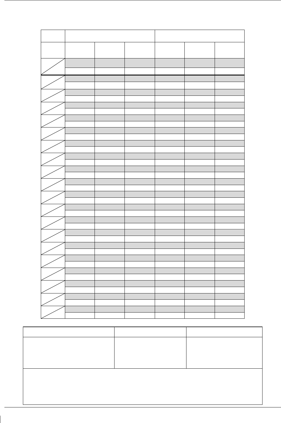
Page 7-24 G1000/GFC700 System Maintenance Manual – C90A/C90GT/C90GTi King Air
Revision G 190-00682-01
Table 7-1. Airspeed and Altitude Table
Test
Point Altitude Airspeed
PFD1 PFD2 STBY PFD1 PFD2 STBY
ALT
AS Tolerance Tolerance Tolerance Tolerance Tolerance Tolerance
Actual Actual Actual
Actual Actual Actual
-1000
50
+/-20 +/-20 +/-20 +/-2 +/-2 +/-5
0
N/A
+/-20 +/-20 +/-20 N/A N/A N/A
500
50
+/-20 +/-20 +/-20 +/-2 +/-2 +/-5
1000
50
+/-20 +/-20 +/-20 +/-2 +/-2 +/-5
1500
50
+/-25 +/-25 +/-25 +/-2 +/-2 +/-5
2000
50
+/-30 +/-30 +/-30 +/-2 +/-2 +/-5
3000
80
+/-30 +/-30 +/-30 +/-2 +/-2 +/-5
4000
80
+/-35 +/-35 +/-35 +/-2 +/-2 +/-5
6000
80
+/-40 +/-40 +/-40 +/-2 +/-2 +/-5
8000
80
+/-60 +/-60 +/-60 +/-2 +/-2 +/-5
10000
120
+/-80 +/-80 +/-80 +/-2 +/-2 +/-5
12000
120
+/-90 +/-90 +/-90 +/-2 +/-2 +/-5
14000
150
+/-100 +/-100 +/-100 +/-2 +/-2 +/-5
16000
180
+/-110 +/-110 +/-110 +/-2 +/-2 +/-5
18000
210
+/-120 +/-120 +/-120 +/-2 +/-2 +/-5
20000
210
+/-130 +/-130 +/-130 +/-2 +/-2 +/-5
22000
100
+/-140 +/-140 +/-140 +/-2 +/-2 +/-5
25000
100
+/-155 +/-155 +/-155 +/-2 +/-2 +/-5
30000
100
+/-180 +/-180 +/-180 +/-2 +/-2 +/-5
Aircraft S/N: _____________________ Date: __________________ Operator: ___________________
ADTS
Make: _______________________
Model: _______________________
S/N: _______________________
Cal. Date: _______________________
ADC1
Model: GDC 74B
P/N: 011-01110-____
S/N: ___________________
Cal. Date: ________________
ADC2
Model: GDC 74B
P/N: 011-01110-____
S/N: ___________________
Cal. Date: ________________
Leak Check Static System at 30,000 ft, 120 kts (pass if <200 ft in 1 min)
Pilot: _____________ Feet/Min
Copilot: ___________ Feet/Min
Leak Check Pitot System at 226 kts (pass if <1 KIAS in 1 min)
Pilot: _____________ KIAS/Min
Copilot: ___________ KIAS/Min
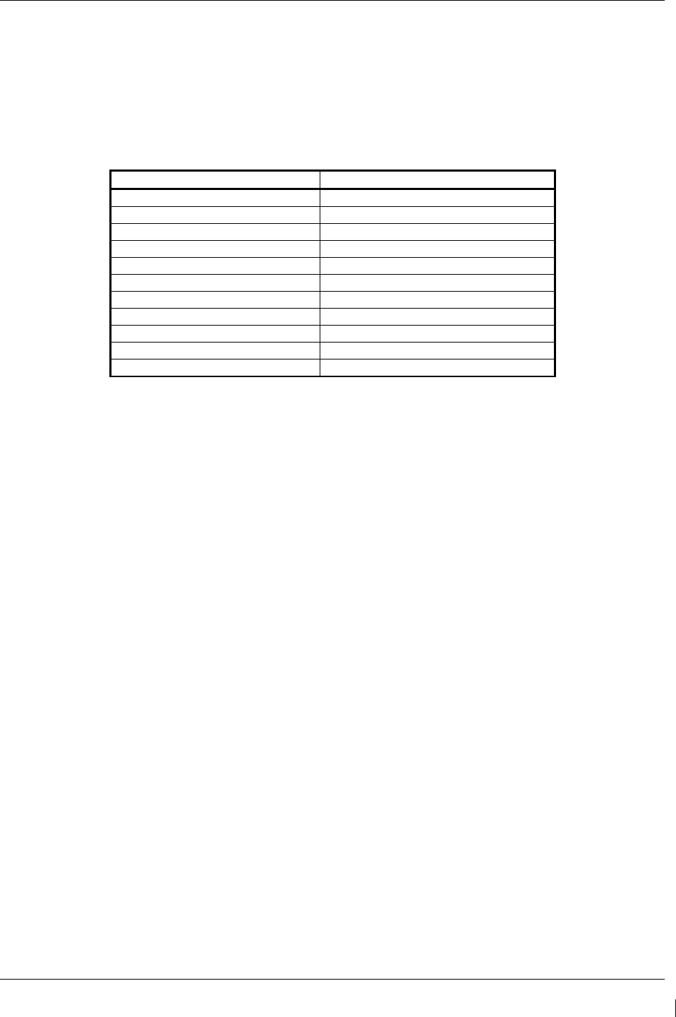
G1000/GFC700 System Maintenance Manual – C90A/C90GT/C90GTi King Air Page 7-25
190-00682-01 Revision G
7.6.2
Static Port Vertical Speed (Rate of Climb) Test
1. Command ADTS to change the altitude at the rates shown in the table below.
2. Wait for ADTS to report that target rates have been achieved.
3. Verify that the Rate of Climb reported by the Vertical Speed field on PFD1 and PFD2 are within
the tolerances specified in Table 7-2:
Table 7-2. Vertical Speed Table
Vertical Speed, feet/minute Allowed tolerance, ±feet/minute
6000 100
2000 100
1000 50
500 45
200 45
0 N/A (No VS Display)
-200 45
-500 45
-1000 50
-2000 100
-6000 100
7.6.3
OAT Probe Check
Ensure on-side sensors for PFD1 and PFD2. Ensure the outside air temperature (OAT) probes and a
calibrated thermometer stabilize at ambient temperature. Verify that the OAT measurement shown on
PFD1 and PFD2, in degrees Celsius, indicate within 2 °C of the ambient temperature as measured by the
calibrated thermometer.
If no other service is to be performed, continue to the return-to-service checks in Section 8.

Page 7-26 G1000/GFC700 System Maintenance Manual – C90A/C90GT/C90GTi King Air
Revision G 190-00682-01
7.7 GRS 77 AHRS / GMU 44 Magnetometer
Original GRS 77 is Reinstalled
If the original GRS 77 was reinstalled, then no software loading is required. This does not include units
that were returned for repair as their software and configuration files are deleted during the repair testing
process.
If the GRS rack was not removed or loosened, continue to the GRS/GMU Test (Section 7.7.6).
If the GRS rack was removed or loosened, continue to the GRS/GMU Calibration Procedures (Section
7.7.1).
Original GRS 77 Installed in Opposite Locations for Troubleshooting
If the original GRS #1 and GRS #2 are installed in opposite locations (GRS #1 and GRS #2 in opposite
unit racks), no software loading is required.
If the GRS rack(s) was not removed or loosened, continue to the GRS/GMU Test (Section 7.7.6).
If the GRS rack(s) was removed or loosened, continue to the GRS/GMU Calibration Procedures (Section
7.7.1).
New Repaired or Exchange GRS 77 is Installed
If the repaired or exchange GRS 77 was replaced with a new unit then software must be loaded and the
unit must be calibrated. Continue to Section 3.9 for software loading. Then, proceed as follows:
If the GRS rack(s) was not removed or loosened, continue to the GRS/GMU Test (Section 7.7.6).
If the GRS rack(s) was removed or loosened, continue to the GRS/GMU Calibration Procedures (Section
7.7.1).
New GRS 77 Configuration Module is Installed
If the GRS 77 configuration module was replaced, no software loading is required. Continue to the
GRS/GMU Calibration Procedures (Section 7.7.1).
Original GMU 44 is Reinstalled
If the original GMU 44 was reinstalled, then no software loading is required. This does not include units
that were returned for repair as their software and configuration files are deleted during the repair testing
process. Continue to the GRS/GMU Test (Section 7.7.6).
Original GMU 44 Installed in Opposite Locations for Troubleshooting
If the original GMU #1 and GMU #2 are installed in opposite locations (GMU #1 and GMU #2 in
opposite unit racks), no software loading is required. However, performing the Magnetometer Calibration
Procedure is required. Continue to the GRS/GMU Test (Section 7.7.6).
New Repaired or Exchange GMU 44 is Installed
If the repaired or exchange GMU 44 was replaced with a new unit then software must be loaded.
Continue to Section 3.9 for software loading. Then continue to the GRS/GMU Calibration Procedures
(Section 7.7.1).

G1000/GFC700 System Maintenance Manual – C90A/C90GT/C90GTi King Air Page 7-27
190-00682-01 Revision G
7.7.1
GRS/GMU Calibration Procedures
GRS/GMU Recalibration Criteria
There following calibration procedures are provided for the GRS 77 and GMU 44:
• Pitch/Roll Offset: (Procedure A1, PROVIDED IN SECTION 7.7.2)
• Magnetometer Calibration: (Procedure B, PROVIDED IN SECTION 7.7.4)
• Engine Run-Up Vibration Test: (Procedure D, PROVIDED IN SECTION 7.7.5)
• Magnetometer Interference Test: (Procedure E, PROVIDED IN SECTION 5.15.4)
When ready to perform the procedures, shut the PFDs and MFD off by pulling the PFD and MFD circuit
breakers. Restart all displays in configuration mode. Follow the steps given for each procedure on-screen
at the GRS/GMU CALIBRATION page. Note that the CALIBRATE command cannot be selected and
activated until the installer acknowledges all required steps have been carried out by pressing the ENT
key on each step.
Table 7-3. Required GRS/GMU Calibrations
Condition
Calibrations Required
Procedure A1:
GRS 77
Pitch/Roll
Offset
Procedure B:
GRS/GMU
Magnetic
Calibration
Procedure D:
Engine Run-up
Vibration
Test
Either GMU 44 was removed and
reinstalled. (no change in serial number)
None Required.
Continue to GRS/GMU Test section.
GMU 44 was replaced with new unit.
(New serial number) X
GRS 77 AHRS was removed and/or
replaced. The mounting tray was NOT
removed and the mounting tray bolts were
NOT loosened.
None Required.
Continue to GRS/GMU Test section.
GRS 77 AHRS was removed and/or
replaced. The mounting tray WAS removed
and/or mounting tray bolts WERE loosened.
X
X
X
GRS 77 AHRS Configuration Module was
replaced. X X X
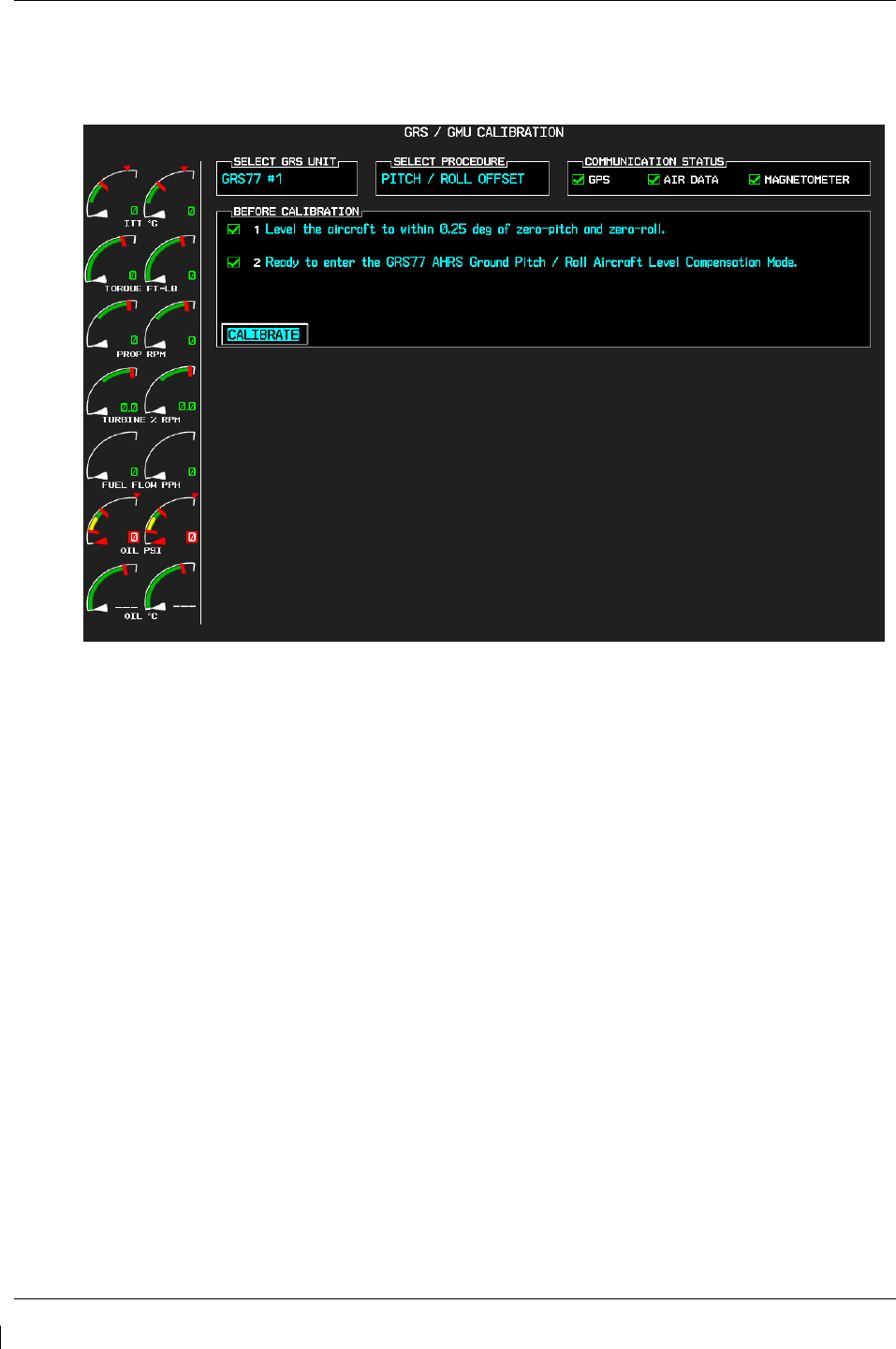
Page 7-28 G1000/GFC700 System Maintenance Manual – C90A/C90GT/C90GTi King Air
Revision G 190-00682-01
7.7.2
Procedure A1: GRS 77 Pitch/Roll Offset Calibration
This procedure must be performed for both GRS 77 units installed in the aircraft. This first procedure
must be carried out with the engine off.
Figure 7-6. GRS 77 Pitch/Roll Offset Calibration Page
1. Level the aircraft to within ±0.25° of zero pitch and zero roll using a digital level. (Follow
instructions in King Air Model 90 Series Maintenance Manual, listed in Table 1-2, for leveling)
2. Start the G1000 system in Configuration mode.
3. Go to the GRS Page Group and select the GRS/GMU Calibration page at the PFD. This page is
protected and the following softkey password must be entered at the PFD to continue:
a) 9
b) 10
c) 11
d) 12 (Far Right softkey)
4. Ensure that the No. 1 GRS 77 is selected in the SELECT GRS UNIT window on the PFD.
a) Activate the cursor and highlight the SELECT PROCEDURE window and select
PITCH/ROLL OFFSET.
b) Press the ENT key.
c) Use the cursor to highlight the BEFORE CALIBRATION window.
d) Follow the checklist items displayed on the PFD and press the ENT key as each step is
completed or confirmed.
e) When the CALIBRATE field is blinking, press the ENT button to begin the
procedure.

G1000/GFC700 System Maintenance Manual – C90A/C90GT/C90GTi King Air Page 7-29
190-00682-01 Revision G
f) After several seconds, a new checklist appears in the lower half of the PFD. Press the
ENT key as each step is confirmed. When the CONFIRM AIRCRAFT IS LEVEL
field is blinking, press the ENT key to continue.
5. The result of the pitch/roll offset compensation is displayed on the PFD. If successful, the AHRS
records the required pitch and roll offsets, informs the operator of a successful conclusion and
returns to normal operation.
6. Press the ENT key on the PFD to conclude this procedure for GRS 77 #1.
7. Repeat steps 1 through 6 for GRS 77 #2.
NOTE
The Magnetometer Calibration Procedure that follows in Section 7.7.4
(Calibration Procedure B) must be carried out at a site that is determined
to be free of magnetic disturbances. If it is unsure whether the site is
‘clean’ the technician should verify that the site is ‘clean’ by following
the guidance provided in Section 7.7.3. The technician may skip Section
7.7.3 if the site condition is acceptable.

Page 7-30 G1000/GFC700 System Maintenance Manual – C90A/C90GT/C90GTi King Air
Revision G 190-00682-01
7.7.3
Compass Rose Evaluation of Magnetic Disturbances for Magnetometer
Calibration Procedure (Optional)
NOTE
Typically, a compass rose is an acceptable location to perform the
magnetometer calibration procedure. However, because not all compass
roses are well maintained, even an existing compass rose should be
regularly evaluated using the method described here to determine if it is
free of magnetic disturbances. If evaluation of an existing compass rose
indicates that magnetic disturbances are present, then an alternative
location must be found to perform the Magnetometer Calibration
Procedure.
A G1000-equipped airplane that has completed the pitch/roll offset compensation procedure (Procedure
A-1, Section 7.7.2) can be used to evaluate a candidate site for magnetic disturbances and determine
whether it is a suitable location to perform the magnetometer calibration procedure. The magnetometer
calibration procedure itself contains the logic to simultaneously survey the location for magnetic
cleanliness while it is computing the magnetometer calibration parameters.
In order to evaluate a candidate site, the Magnetometer Calibration Procedure must be performed twice:
once turning clockwise around the site, and once turning counter-clockwise. Both times, the procedure
should be conducted as described in Section 7.7.4 of this document, with the exception of the direction of
turns around the site.
NOTE
Although Section 7.7.4 indicates that the Magnetometer Calibration
Procedure should be performed by making a series of clockwise turns
around the site, the procedure can also be performed by making counter-
clockwise turns for the purpose of evaluating the site for magnetic
disturbances.
If, upon completion of the Magnetometer Calibration Procedure in each clockwise and counter-clockwise
direction, the PFD displays the “CALIBRATION SUCCESSFUL / SITE IS CLEAN” message, then the
candidate site is sufficiently free of magnetic disturbances and is acceptable for performing the
Magnetometer Calibration Procedure. It is important to obtain successful result in both the clockwise and
counter-clockwise directions to ensure that the magnetometer sweeps over a large enough area at the
candidate site.
If, upon completion of the Magnetometer Calibration Procedure in either of the two directions, the PFD
displays either the “MAG FIELD AT SITE NOT UNIFORM”, or “MAG FIELD AT SITE DIFFERS
FROM IGRF MODEL” message, then the site contains magnetic disturbances that are too large.

G1000/GFC700 System Maintenance Manual – C90A/C90GT/C90GTi King Air Page 7-31
190-00682-01 Revision G
7.7.4
Procedure B: GRS 77/GMU 44 Magnetic Calibration
NOTE
Procedure A-1 (Section 7.7.2) must first be successfully accomplished before performing
Procedure B, only for situations where the GRS 77 was replaced with a new unit.
Calibration Procedure B must be carried out on a compass rose in order to guarantee measurements free
of environmental magnetic disturbances. Attempting to carry out this maneuver on a typical ramp area
may not yield a successful calibration. The accuracy of the AHRS cannot be guaranteed if this calibration
is not performed on a magnetically clean compass rose. If the compass rose condition is not known, it is
recommended that the technician follow the guidance in Section 7.7.3.
1. Start the aircraft engine following the procedures referenced in the appropriate King Air AFM or
AFMS as listed in Table 1-2.
2. After aircraft engine startup, taxi the aircraft to a properly calibrated compass rose.
3. At the compass rose, align the aircraft to a heading of magnetic north (±5°).
CAUTION
CALIBRATION PROCEDURE B MUST BE CARRIED OUT ON A COMPASS ROSE IN
ORDER TO GUARANTEE MEASUREMENTS FREE OF ENVIRONMENTAL MAGNETIC
DISTURBANCES. ATTEMPTING TO CARRY OUT THIS MANEUVER ON A TYPICAL
RAMP AREA MAY NOT YIELD A SUCCESSFUL CALIBRATION. THE ACCURACY OF
THE AHRS CANNOT BE GUARANTEED IF THIS CALIBRATION IS NOT PERFORMED
ON A MAGNETICALLY CLEAN COMPASS ROSE OR EQUIVALENT.
NOTE
This procedure provides instructions for calibrating both GRS 77 magnetometers separately. It is
acceptable to calibrate both GRS 77 magnetometers simultaneously by putting both PFD 1 and
PFD 2 in configuration mode and following the procedure below, using PFD 1 to calibrate GRS
#1 and PFD 2 to calibrate GRS #2.
4. Restart the PFD and MFD in configuration mode.
5. Go to the GRS Page Group on the PFD.
6. Select the GRS/GMU Calibration page and enter the following softkey password:
a) 9
b) 10
c) 11
d) 12 (far right softkey)
7. Press the FMS small knob to highlight GRS 77 #1. The FMS small knob can now be turned to
select either GRS 77 #1 or GRS 77 #2 for calibration. Press the ENT key after selecting the
desired GRS 77 unit to calibrate. The SELECT PROCEDURE field is not blinking.
8. Using the FMS small knob, select MAGNETOMETER. Press the ENT button.
9. Use the cursor to highlight the BEFORE CALIBRATION window.
10. Follow the checklist items displayed on the PFD and press the ENT key as each one is completed
or confirmed. When the CALIBRATE field is blinking, press the ENT key to begin the
procedure.

Page 7-32 G1000/GFC700 System Maintenance Manual – C90A/C90GT/C90GTi King Air
Revision G 190-00682-01
11. The PFD display advises the operator when to turn the aircraft, when to stop, and when to turn
again.
12. Upon instruction to turn, taxi the aircraft in a right turn. After approximately 25° to 30° of turn
from the last heading, the PFD display advises the operator to stop the aircraft.
NOTE
Due to the difficulties in executing smooth, accurate turns the PFD may incorrectly
interpret a station and instruct to “HOLD POSITION” prior to full completion of a 30°
turn. If this scenario is encountered, it is best for the operator to ignore the “HOLD
POSITION” command and instead use outside references to complete the approximate
30° turn. Instead of using the PFD instruction to turn as a real-time indication of when to
turn, simply judge the 30° (±5°) turn increments of the aircraft by using the compass rose
radials. Dwelling at these 30° increments for the time recommended by the PFD should
result in successful calibration.
13. The PFD guides the operator to dwell at multiple headings around a complete circle.
NOTE
Due to high winds or excessive airframe vibration, the operator may encounter a
condition where the PFD restarts the 18-second countdown without full completion of the
previous countdown. If this is encountered more than once for a given station, the
operator should begin turning to the next station (approximately 30°). A minimum of 2
successful stations per quadrant is required, where a successful station is a full 18-second
countdown followed by instruction to move. Ensure that at least 2 stations per quadrant
are completed. Thus, it may sometimes be required to dwell at a station after a
countdown restart. A maximum of 30 stations is allowed for the entire calibration
procedure. If too many countdown restarts are encountered, the calibration will fail with
the message, “TOO MANY STATIONS.”
14. Repeat the turn-and-stop process until the PFD advises that a successful calibration is complete.
The GRS 77 AHRS then enters its normal operational mode. Press the ENT button on the PFD to
conclude this procedure.
15. Repeat steps 4 through 14 for GRS 77 #2.
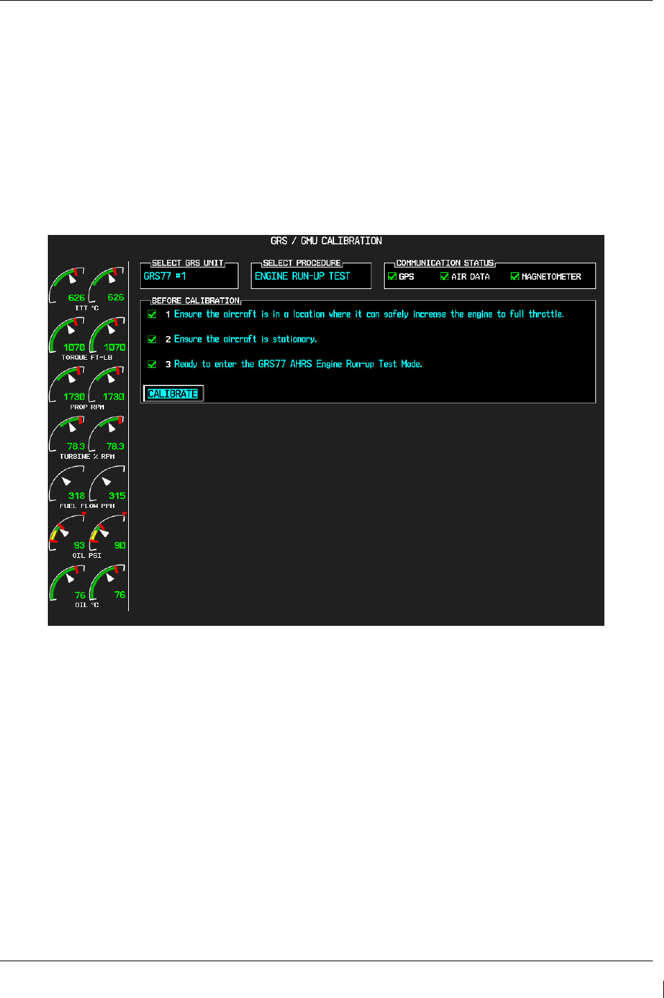
G1000/GFC700 System Maintenance Manual – C90A/C90GT/C90GTi King Air Page 7-33
190-00682-01 Revision G
7.7.5
Procedure D: Engine Run-Up Vibration Procedure
NOTE
Calibration Procedure D is performed in order to guarantee that the AHRS mounting is
sufficiently rigid and insensitive to vibration. This procedure must be performed for both GRS
77 units installed in the aircraft. Calibration Procedures A1 and B (Sections 7.7.2 and 7.7.4
respectively) are not required prior to this procedure.
Figure 7-7, Engine Run-Up Test Page
1. Press the FMS small knob to highlight GRS 77 #1. The FMS small knob can now be turned to
select either GRS 77 #1 or GRS 77 #2 for calibration. Press the ENT key after selecting the
desired GRS 77 unit to calibrate. The SELECT PROCEDURE field is not blinking.
2. Initiate the AHRS engine run-up vibration test procedure by performing the following steps:
a) Select the ENGINE RUN-UP TEST procedure and press the ENT key.
b) Follow the checklist items displayed on the PFD, and press the ENT key as each one is
completed or confirmed. When the CALIBRATE field is blinking, press the ENT key to
begin the procedure.
3. The PFD display instructs the operator to gradually increase power from idle to full throttle and
back to idle over a period of 2-4 minutes.
4. When the operator has completed the engine run-up and the engine is back to an idle setting,
press the ENT key to indicate that the process is complete. When this is done, the TEST
COMPLETE field stops blinking.

Page 7-34 G1000/GFC700 System Maintenance Manual – C90A/C90GT/C90GTi King Air
Revision G 190-00682-01
5. The PFD informs the operator if the installation has passed or failed the vibration test. If the test
fails, the specific measurements causing the failure are identified and associated numeric values
are displayed on the PFD.
NOTE
Should a failure occur, the technician may perform the Engine Run-up test up to 3 times successively
before corrective action must be taken. If the test does not pass after three attempts, then the installation
should not be considered reliable until the source of the vibration problem is identified and remedied. In
the event of repeated failure of the engine run-up test, record the values that are reported to be out of
range for future reference.
The following are potential causes for failure of the engine run-up test:
a) Vibration motion of GRS77 and/or GMU44 caused by neighboring equipment and/or
supports.
b) Mounting screws and other hardware for GRS77 and/or GMU44 not firmly attached.
c) GRS77 connector not firmly attached to unit.
d) Cabling leading to GRS77 or GMU44 not firmly secured to supporting structure.
e) An engine / propeller that is significantly out of balance.
6. Press the ENT key on the PFD to conclude this procedure
7. Repeats steps 1 through 6 for GRS 77 #2 and proceed to Section 7.7.6.
7.7.6
GRS/GMU Test
The aircraft can now be taxied back and the engine can be shut down for final testing. Restart the
displays in normal mode to conduct final system checks. When the PFDs power up in normal mode, the
AHRS attitude and heading information displayed should become valid within 1 minute of power-up, as
shown in Figure 7-8 (provided both GPS receivers have a valid position; if GPS is unavailable, AHRS
initialization may take as long as 2 minutes).
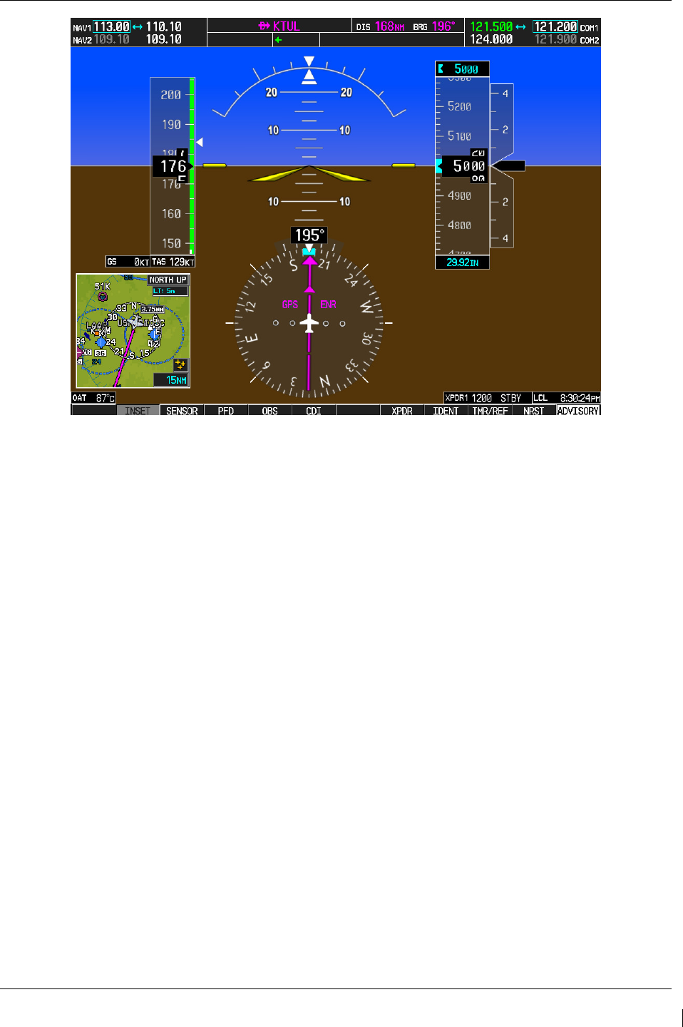
G1000/GFC700 System Maintenance Manual – C90A/C90GT/C90GTi King Air Page 7-35
190-00682-01 Revision G
Figure 7-8. Normal Mode AHRS Check
If no other service is to be performed, continue to the return-to-service checks in Section 8.

Page 7-36 G1000/GFC700 System Maintenance Manual – C90A/C90GT/C90GTi King Air
Revision G 190-00682-01
7.8 GDL 69A XM Data Link
Original GDL 69A is Reinstalled
No software or configuration loading is required if the removed GDL 69A is re-installed. This does not
include units that were returned for repair as their software and configuration files are deleted during the
repair testing process. Continue to the GDL 69A Test (Section 7.8.1).
New Repaired or Exchange GDL 69A is Installed
If a new repaired or exchange GDL 69A is installed, the correct software and configuration files must be
loaded to the unit, then the XM Satellite Radio subscription must be reactivated. See Section 3.9 and the
XM Activation Instructions listed in Table 1-2. Then continue to the GDL 69A Test (Section 7.8.1).
7.8.1
GDL 69A Test
If an XM Satellite Radio subscription has already been activated for the GDL 69A, then power up the
G1000 and go to the AUX – XM INFORMATION page and verify that the GDL 69A is working
properly. Refer to the Cockpit Reference Guide, listed in Table 1-2, for details on XM Radio weather and
music operation.
If the GDL 69A is replaced (new unit), the owner must re-activate the subscription, using the new
GDL 69A’s Radio ID number(s). Refer to the GDL 69A/69AA XM Satellite Radio Activation
Instructions, listed in Table 1-2, for details on the activation process.
As a final operations check, make sure there are no MANIFEST errors shown on the PFD for the
GDL 69A.
If no other service is to be performed, continue to the return-to-service checks in Section 8.
7.9 GSA 80/81 Servos
Original Servo(s) Reinstalled
No software loading is required if the removed servo(s) is re-installed. This does not include units that
were returned for repair as their software and configuration files are deleted during the repair testing
process. Continue to the return-to-service checks in Section 8.
New Repaired or Exchange Servo(s) Installed
If a new repaired or exchange servo is installed, the correct software files and certification gains must be
loaded to the unit. See Section 3.9 and then continue to the return-to-service checks in Section 8.
NOTE
Refer to the appropriate servo installation drawing listed in Table 1-2.
If no other service is to be performed, continue to the return-to-service checks in Section 8.

G1000/GFC700 System Maintenance Manual – C90A/C90GT/C90GTi King Air Page 7-37
190-00682-01 Revision G
7.10 GCU 475 FMS Controller
Original GCU 475 Reinstalled
No software or configuration loading is required if the removed GCU 475 is re-installed. This does not
include units that were returned for repair as their software and configuration files are deleted during the
repair testing process. Continue to the GCU 475 Test (Section 7.10.1).
New Repaired or Exchange GCU 475 Installed
If a new repaired or exchange GCU 475 is installed, the correct software and configuration files must be
loaded to the unit. See Section 3.9 and then continue to the GCU 475 Test (Section 7.10.1).
7.10.1
GCU 475 Test
Perform the following key and knob presses and knob rotations on the GCU 475, and verify the
actions on the MFD.
1. Rotate the large FMS knob and verify that the page groups change.
2. Rotate the small FMS knob and verify that the pages change within the page groups.
3. Use the large FMS knob to display the MAP page group and the small FMS knob to display the
NAVIGATION MAP page.
4. Rotate the RANGE knob to the right and verify the map display zooms out.
5. Rotate the RANGE knob to the left and verify the map display zooms in.
6. Press the RANGE knob to get the pointer on the map display.
7. Move the RANGE knob to the left and verify the pointer moves to the left.
8. Move the pointer up, right and down and verify that the pointer moves accordingly.
9. Press the RANGE knob to stop displaying the pointer.
10. Press the left and right arrowheads of the SOFTKEY SELECT keys. Verify softkeys highlighting
on the MFD changes.
11. Press the SEL key to select one of the softkeys.
12. Press the key to display the DIRECT TO page.
13. Use the keypad to type KIXD (or alternate local airport) and verify KIXD is displayed on the
MFD.
14. Press the SPC key to add a space and then the BACK key to delete the space.
15. Press the CLR key to clear the field.
16. Type K34 and then press the ENTER key twice. Verify that the flight path to K34 is displayed on
the map.
17. Press the FPL key to open the ACTIVE FLIGHT PLAN page. Press the FPL key again to close
it.
18. Press the PROC key to open the PROCEDURES page. Press the PROC key again to close it.
19. Press the MENU key to open the MENU page. Press the MENU key again to close it.
If no other service is to be performed, continue to the return-to-service checks in Section 8.

Page 7-38 G1000/GFC700 System Maintenance Manual – C90A/C90GT/C90GTi King Air
Revision G 190-00682-01
7.11 GMC 710 AFCS Controller
Original GMC 710 Reinstalled
No software or configuration loading is required if the removed GMC 710 is re-installed. This does not
include units that were returned for repair as their software and configuration files are deleted during the
repair testing process. Continue to the GMC 710 Test (Section 7.11.1).
New Repaired or Exchange GMC 710 Installed
If a new repaired or exchange GMC 710 is installed, the correct software and configuration files must be
loaded to the unit. See Section 3.9 and then continue to the GMC 710 Test (Section 7.11.1).
7.11.1
GMC 710 Test
Perform a basic operational check on the GMC 710. The following knob, wheel and key presses and
rotations are to be performed on the GMC 710.
1. Ensure the G1000 is operating in normal mode and the autopilot is operational.
2. Press the FD key a few times; verify the Flight Director display on PFD1 toggles on and off.
Leave the flight director displayed.
3. Press the XFR key and verify the white-illuminated arrowhead points in the opposite direction.
Verify the green arrow displayed at the top of PFD 1 also points in the same direction.
4. Rotate the ALT SEL knob and verify the altitude bug, displayed on PFD 1 altitude tape, moves.
5. Rotate the UP/DN wheel and verify the flight director moves in the vertical direction.
6. Press the HDG key and verify the white illumination appears next to the key. Rotate the HDG
knob and verify the heading bug, displayed on PFD 1 compass card, moves and the flight director
follows.
7. Press the HDG knob and verify the heading bug centers.
8. Press the YD key and verify the white illumination appears next to the key.
9. Press the VS key and verify the white illumination appears next to the key.
10. Press the FLC key and verify the white illumination appears next to the key.
If no other service is to be performed, continue to the return-to-service checks in Section 8.

G1000/GFC700 System Maintenance Manual – C90A/C90GT/C90GTi King Air Page 7-39
190-00682-01 Revision G
7.12 GWX 68 Weather Radar
Original GWX 68 Reinstalled
No software or configuration loading is required if the removed GWX 68 is re-installed. This does not
include units that were returned for repair as their software and configuration files are deleted during the
repair testing process. Continue to the GWX 68 Test (Section 7.12.1).
New Repaired or Exchange GWX 68 Installed
If a new repaired or exchange GWX 68 is installed, the correct software and configuration files must be
loaded to the unit. See Section 3.9 and then continue to the GWX 68 Test (Section 7.12.1).
7.12.1
GWX 68 Test
Operation of the GWX 68 Weather Radar is accomplished using the MFD/GCU 475. Refer to
G1000/C90A/C90GT/C90GTi King Air Cockpit Reference Guide, listed in Table 1-2, for basic operation.
NOTE
Before energizing the equipment, be sure microwave radiation safety precautions including
both fuel and personnel safety considerations have been observed. These include clearing all
personnel to an area beyond the maximum permissible exposure level (MPEL) boundary. The
MPEL for the GWX 68 is 11 feet.
1. On the GCU, turn the large FMS knob to select the Map Page Group then turn the small FMS knob
to select the Weather Radar page.
2. Select the MODE softkey.
3. Select the STANDBY softkey to initiate the one minute warm-up period. Verify the radar enters the
standby mode after the warm-up is complete.
4. Select the MODE softkey.
5. Select the WEATHER softkey. After reading the CAUTION statement, turn the large FMS knob to
select YES. Press the GCU ENT key.
6. Select the STAB ON softkey to activate antenna stabilization or select the STAB OFF softkey to
deactivate. Verify the current stabilization condition is shown in the upper right of the weather radar
display.
7. Select the BACK softkey.
8. Select the VERTICAL softkey.
9. Select the TILT softkey to activate the cursor in the TILT field.
10. On the GCU, turn the small FMS knob to select the desired antenna tilt angle. Press the GCU ENT
key. Press the GCU FMS knob to remove the cursor.
11. Select the GAIN softkey to activate the cursor in the GAIN field.
12. On the GCU, turn the small FMS knob to adjust the gain for the desirable level. Verify the gain
setting is visible in the gain field as a movable horizontal bar in a flashing box and the line pointer is
a reference depicting the calibrated position. Press the FMS knob to remove the cursor.
13. On the GCU, select the GAIN softkey again to recalibrate the gain. Verify ‘CALIBRATED’ is
displayed in the GAIN field.
14. Select the MODE softkey.
15. Select the OFF softkey.

Page 7-40 G1000/GFC700 System Maintenance Manual – C90A/C90GT/C90GTi King Air
Revision G 190-00682-01
If no other service is to be performed, continue to the return-to-service checks in Section
8
.
7.13 Traffic (Non-Garmin) System Functional Check
1. Select the TRAFFIC MAP page on the MFD.
2. Verify that the STANDBY, OPERATE, TEST and ALT MODE soft keys are available on the
bottom of the MFD. Verify that an
operating mode; STANDBY, OPERATE, or TEST
(not TAS
FAIL) is displayed in the upper left corner of the traffic map. Verify that NO DATA is not
displayed in yellow in the center of the display over the aircraft symbol.
NOTE
If the ALT MODE softkey is not displayed, the G1000 has not been properly configured for the
traffic system. Reference Section 3.9.4.4, “Traffic System Option” to enable the traffic system.
3. Press the OPERATE soft key and verify that OPERATING is displayed in the upper left corner of
the traffic map.
4. Press the STANDBY soft key and verify that STANDBY is displayed in the upper left corner of
the traffic map.
5. Press the TEST soft key and verify that TEST is displayed in the upper left corner of the traffic
map and a traffic test pattern is displayed. Upon completion of the test, verify that “TAS
SYSTEM TEST OK” is heard over the cockpit speaker.
NOTE
This annunciated traffic system test message may be different from the traffic system installed on
subject aircraft.
6. Open the TRFC circuit breaker on the avionics circuit breaker panel. On the MFD, verify that
NO DATA is displayed in yellow after several seconds.
7.
Close the TRFC circuit breaker on the avionics circuit breaker panel and verify that NO DATA is
removed after several seconds.
If no other service is to be performed, continue to the return-to-service checks in Section 8.

G1000/GFC700 System Maintenance Manual – C90A/C90GT/C90GTi King Air Page 7-41
190-00682-01 Revision G
7.14 Lightning Detection Functional Check
Reference Section 3.9.4.5, Stormscope (WX-500) Configuration, for configuring Stormscope.
This procedure assumes familiarity with the set-up and operation of the WX-PA portable analyzer kit.
1. Apply power to the WX-500 and verify that no failed test messages appear. If fault messages do
appear, refer to the WX-500 Installation Manual for troubleshooting.
2. Following successful power up, verify the following modes:
a. Access to both 360° and ARC weather view modes.
b. All available ranges can be displayed.
c. Access to the cell mode and strike mode.
d. Strike counter is displayed in all weather modes and ranges.
3. Key COM1 and COM2 several times on different frequencies representing the lower, mid and
upper portion of the VHF COM frequency band. Verify keying of COM1 or COM2 does not
cause strike data to appear on the MFD.
4. Operate DME, XPDR 1, XPDR 2 and weather radar. Verify these systems do not cause strike
data to appear on the MFD.
5. Connect the WX-PA cable to the WX-PA antenna.
6. Position the WX-PA antenna on the WX-500 antenna. Ensure the connection is tight. If
necessary, use tape to secure the WX-PA antenna. Ensure the “FORWARD” arrows are aligned
and the WX-PA antenna suction cups are positioned forward of center along the longitudinal axis.
7. Secure the WX-PA cable to the aircraft with the attached suction cup and route the cable to the
cockpit.
8. Connect the remaining cable end to the WX-PA.
9. Power up the WX-PA and verify the WX-500 is in the weather mapping mode (i.e. 3600 weather
view at the 200 NM range.
10. Set the WX-500 to STRIKE mode; 100 NM range (or next highest available range).
11. Select the Continuous Out mode displayed on the WX-PA menu and press MENU/ENTER.
12. Select the bottom mount antenna configuration on the WX-PA keyboard (“A” key).
13. Select a cardinal bearing and a range of 120 NM.
14. Use the F1 and F2 keys to adjust range and F3 and F4 keys to adjust heading.
NOTE
The WX-500 will plot data at one-half the range selected on the WX-PA

Page 7-42 G1000/GFC700 System Maintenance Manual – C90A/C90GT/C90GTi King Air
Revision G 190-00682-01
15. Press MENU/ENTER to start the test.
16. Observe the MFD to ensure the proper positioning of the strikes, based on range and azimuth
settings on the WX-PA. Change the cardinal bearings and verify correct test strikes. Verify the
strikes are within 10 degrees of the selected azimuth and plot at 60NM (1/2 120 NM).
17. Verify after 20 seconds of operation the strike counter reads 580 +/-40.
18. After testing for all ranges and bearings indicated, press 2
ND
then MENU/ENTER to return to the
main menu.
19. Select Circular Pattern mode on the WX-PA mode menu and press MENU/ENTER.
20. Select bottom mount antenna configuration on the WX-PA keyboard (“A” key).
NOTE
The MFD should be set at 100 NM (or next highest available range) on the 360 degree weather
screen and in strike mode.
21. Use the F1 and F2 keys to select 120 NM range and press MENU/ENTER to start the test. Verify
the WX-500 plots discharge points at approximately 60 NM.
22. Observe the MFD to ensure the proper positioning of the test strikes. Verify the strikes are within
10 degrees of the 30 degree azimuth increment and within 12 NM of 60 NM,
23. When complete, set WX-PA for 55 NM, set the MFD for 50 NM (or the next highest available
range) and repeat test.
24. On the MFD, verify the sensor plots points just outside of 25 NM and the strikes are within 10
degrees of the 30 degree azimuth and within 5 NM of 27.5 NM.
25. Repeat above setting the MFD for 25 NM (or the next highest available range) and the WX-PA
for 15 NM.
26. On the MFD, verify the positioning of test strikes are within 10 degrees of azimuth and within 2
NM of 7.5 NM.
27. Restart the G1000 in configuration mode by opening the PFD and MFD circuit breakers. While
holding the ENT keys on the PFDs and MFD, restore power by closing the PFDs and MFD
circuit breakers.
28. Select the OTHER page group on the MFD. The STORMSCOPE page is shown by default.
If no other service is to be performed, continue to the return-to-service checks in Section 8.

G1000/GFC700 System Maintenance Manual – C90A/C90GT/C90GTi King Air Page 7-43
190-00682-01 Revision G
7.15 TAWS Functional Check
1. With the G1000 in Normal Mode, use the GCU FMS knob to select the MAP group and TAWS
page on the MFD.
2. Verify that the title at the top of the page reads “MAP – TAWS-B”.
NOTE
If TAWS has not been enabled, the title will read “MAP – TERRAIN PROXIMITY” or “MAP
– TERRAIN”. Refer to section 3.9.7 for TAWS Configuration for configuring TAWS.
3. Press the GCU MENU button and select “Test TAWS” from the pop-up menu. Verify TAWS
test annunciation is displayed on the MFD and both PFDs.
4. After the TAWS test has completed, verify that “TAWS System Test Okay” is heard over the
cockpit speaker.
5. Press the GCU MENU button again and select “Inhibit TAWS” from the pop-up menu and press
ENT on the GCU. Verify “TAWS INHB” is displayed on PFD 1, PFD 2 and MFD.
6. Press the GCU MENU button again and select “Enable TAWS” from the prop-up menu and press
ENT on the GCU. Verify the “TAWS INHB” annunciation on the PFDs and MFD has
extinguished.
7. With a GPS position acquired, shield or disconnect the GPS antennas to remove the GPS signal.
Verify “No GPS Position” shows on the MFD and the “TAWS N/A” and “LOI” annunciations
show on the PFDs.
8. Reconnect or remove the shield from the GPS antennas, and verify the MFD “No GPS Position”
and PFD “TAWS N/A” and “LOI” annunciations are removed once the GPS satellites are
acquired.
9. Pull PFD1 PRI and PFD1 SEC circuit breakers. Re-power PFD1 in configuration mode, and use
the PFD1 FMS knob to select the Audio Alert Configuration page.
10. Ensure cockpit speaker is selected ON. Use the PFD1 FMS knob to highlight each of the
following messages then select PLAY. Verify each of the following audio messages can be
played:
Caution Obstacle (2x) Pull-Up
Caution Terrain (2x) Sink Rate
Don’t Sink Terrain Ahead, Pull-Up (2x)
Obstacle Ahead (2x) Terrain Ahead (2x)
Obstacle Ahead, Pull-Up (2x) Too Low, Terrain
Obstacle (x2); Pull-Up (2x) Terrain (2x); Pull-Up (2x)
Five Hundred
11. Pull the PFD1 PRI and PFD1 SEC circuit breakers, and re-power PFD1 in normal operating
mode.
If no other service is to be performed, continue to the return-to-service checks in Section 8.

Page 7-44 G1000/GFC700 System Maintenance Manual – C90A/C90GT/C90GTi King Air
Revision G 190-00682-01
7.16 FliteCharts Functional Check
Reference Section 3.9.4.11, FliteCharts Configuration, for configuring FliteCharts.
NOTE
This test is not required if ChartView is enabled.
1. With the G1000 in Normal Mode, use the GCU FMS knob to select ‘AUX – System Status’ page,
then select MFD1 DB softkey.
2. Use the small FMS knob to scroll to CHART.
3. Verify “FliteCharts” is displayed in blue text adjacent to “CHART”.
4. Verify the FliteCharts database cycle number is displayed in blue text and the FliteCharts database is
current.
5. Deactivate the cursor and use the GCU large FMS knob to select the Navigation Map Page then
press the SHW CHRT softkey.
6. Verify the airport chart is displayed and the following softkeys are displayed (some softkeys may be
grayed out):
• CHRT OPT
• CHRT
• INFO-1
• DP
• STAR
• APR
• WX
• NOTAM
• GO BACK
7. Press the CHRT OPT softkey and verify the following softkeys are displayed (some softkeys may be
grayed out):
• ALL
• HEADER
• PLAN
• PROFILE
• MINIMUMS
• FIT WDTH
• FULL SCN
• BACK
If no other service is to be performed, continue to the return-to-service checks in Section 8.

G1000/GFC700 System Maintenance Manual – C90A/C90GT/C90GTi King Air Page 7-45
190-00682-01 Revision G
7.17 ChartView Functional Check
ChartView must be enabled using a ChartView Enable Card, as specified in the General Arrangement
Drawing listed in Table 1-2, and a current ChartView database. Reference section 3.9.6, “ChartView
Configuration” for enabling procedures.
NOTE
The required ChartView databases are subscription-based and are to be procured by the aircraft owner
directly from Jeppesen.
1. With the G1000 in Normal Mode, use the GCU FMS knob to select ‘AUX – System Status’ page, then
select MFD1 DB softkey.
2. Use the small FMS knob to scroll to CHART.
3. Verify “ChartView” is displayed in blue text adjacent to CHART.
4. Verify the ChartView database cycle number is displayed in blue text and the ChartView database is
current.
5. Deactivate the cursor and use the large GCU FMS knob to select the Navigation Map Page then press
the SHW CHRT softkey.
6. Verify the airport chart is displayed and the following softkeys are displayed(some softkeys may be
grayed out):
• CHRT OPT • APR
• CHRT • WX
• INFO-1 • NOTAM
• DP • GO BACK
• STAR
7. Press CHRT OPT softkey and verify the following softkeys are displayed (some softkeys may be
grayed out):
• ALL
• HEADER
• PLAN
• PROFILE
• MINIMUMS
• FIT WDTH
• FULL SCN
• BACK
If no other service is to be performed, continue to the return-to-service checks in Section 8.

Page 7-46 G1000/GFC700 System Maintenance Manual – C90A/C90GT/C90GTi King Air
Revision G 190-00682-01
7.18 SafeTaxi Functional Check
The maximum map ranges for enhanced detail are configurable by the flight crew. When zoomed in close
enough to show the airport detail, the map reveals runways with numbers, taxiways with identifying
letters/numbers, and airport landmarks including ramps, buildings, control towers, and other prominent
features. Resolution is greater at lower map ranges. When the aircraft location is within the screen
boundary, including within SafeTaxi ranges, an airplane symbol is shown on any of the navigation map
views for enhanced position awareness.
Any map page that displays the navigation view can also show the SafeTaxi airport layout, within the
maximum configured range. The following is a list of pages where the SafeTaxi feature can be seen:
• Navigation Map Page
• Inset map
• Weather Datalink Page
• Airport Information Page
• Intersection Information Page
• NDB Information Page
• VOR Information Page
• User Waypoint Information Page
• Trip Planning Page
• Nearest Pages
1. Use the FMS knob on the GCU to select the AUX – System Status page and select DBASE
softkey. Use the small FMS knob to scroll to CHART category and verify “FliteCharts” is
displayed in blue text adjacent to “CHART”.
2. Verify the FliteCharts database ‘REGION’, ‘CYCLE’ number, ‘EFFECTIVE’, ‘EXPIRES’, and
‘DISABLES’ dates of the subscription appear in blue text.
3. Use the FMS knob on the GCU to select MAP - Navigation Map page.
4. On the GCU, press MENU. With Map Setup highlighted, press ENT on the GCU. Rotate the
small GCU FMS knob to select the Aviation group and press the ENT key on GCU.
5. Turn the GCU large FMS Knob to scroll through the Aviation Group options to ‘SAFETAXI’.
6. Turn the GCU small FMS Knob to display the range of distances.
7. Turn the GCU FMS Knob to select 5000ft as the distance for maximum SafeTaxi display range,
and then press the GCU ENT key to complete the selection.
8. Using the GCU range knob, select a range of 5000ft or less. Verify SafeTaxi display represents
the current aircraft location and the airport layout.
If no other service is to be performed, continue to the return-to-service checks in Section 8.

G1000/GFC700 System Maintenance Manual – C90A/C90GT/C90GTi King Air Page 7-47
190-00682-01 Revision G
7.19 DME Functional Check
This check verifies that the DME-to-G1000 interface operates correctly.
NOTE
Support for a single Collins DME-42 system is provided as an option in the G1000. If the DME option is
selected, the DME channel one audio level must be adjusted by the procedure contained within Collins
DME-42 Transceiver Repair Manual 523-0772458-00611A, Maintenance Section 523-0772460-006118
to adjust DME channel one audio level. Recommended nominal DME audio output level is 1.32 Vpp +
0.10 Vpp for aircraft with C90A G1000 System Software Version 0636.01 and 4.46 Vpp +0.10 Vpp for
aircraft with C90A G1000 System Software Version 0636.02 and subsequent approved versions.
Procedure must be accomplished by an approved repair station.
1. If DME is not displayed, press the PFD softkeys on PFD1 and PFD2, then press the DME
softkey. Verify the DME window is displayed next to the PFD1 and PFD2 HSI.
2. On PFD1 and PFD2, press the BACK softkey then select DME softkeys. Verify the DME
TUNING screen is displayed.
3. On PFD1 and PFD2, use the large FMS knob to select the NAV1, NAV2 and HOLD modes in
the DME field. Verify that the NAV1, NAV2 and HOLD modes can be selected by turning the
small FMS knob.
4. Set NAV1 and NAV2 frequencies to 108.00 and 117.00 respectively.
5. On PFD1 and PFD2, select the DME NAV1 mode. Verify that the DME window display is set to
the NAV1 frequency of 108.00.
6. On PFD1 and PFD2, select the DME NAV2 mode by pressing the ENT softkey. Verify that the
DME window display is set to the NAV2 frequency of 117.00.
7. On PFD1 and PFD2, select the DME HOLD mode by using the FMS knob. Verify that the last
selected NAV frequency of 117.00 remains the same when the NAV2 frequency is changed.
Deselect DME HOLD.
8. On the NAV Test Set, set up a DME test and note the nav frequency. Tune NAV 1 to the test set
frequency and set PFD1 and PFD2 DME MODE to NAV1. Set NAV 2 to a frequency other than
the test set frequency.
9. Verify that the DME distance on PFD1 and PFD2 match the test set.
10. Select, or verify selected, DME and SPKR buttons on GMA1 and GMA2 audio panels to select
the DME audio and select speaker to ON. Verify that the DME audio can be heard over the
cockpit speakers.
11. On PFD1 and PFD2, set the DME mode to NAV2 and verify that the DME distance is dashed
out.
12. Tune NAV 2 to the test set frequency. Set NAV 1 to a frequency other than the test set frequency.
13. Verify that the DME distance on PFD1 and PFD2 match the test set.
If no other service is to be performed, continue to the return-to-service checks in Section 8.

Page 7-48 G1000/GFC700 System Maintenance Manual – C90A/C90GT/C90GTi King Air
Revision G 190-00682-01
7.20 ADF Functional Check
This check verifies that the ADF / G1000 interface operates correctly.
1. Press the PFD softkey on PFD1 and PFD2. Toggle the BRG1 and BRG2 softkey until the ADF
bearing is shown on PFD1 and PFD2.
2. Verify that the ADF window is not invalid (no red ‘X’).
3. Using the ADF control head select a known valid local ADF. Verify that the ADF bearing pointer
moves towards a bearing and stabilizes.
4. Select ADF and SPKR on GMA1 and GMA2. Using the ADF control head, select, ANT mode.
Verify that the audio from the station tuned can be heard on the pilots and copilots headset and
cockpit speaker.
5. Increment the ADF volume control from full low to full high. Verify the volume increases and
decreases appropriately over pilots and copilots headset and cockpit speaker.
If no other service is to be performed, continue to the return-to-service checks in Section 8.
7.21 Aircraft Weight Configuration Functional Check
The following functional check will verify that the Maximum Takeoff Weight (MTOW) and Maximum
Zero Fuel Weight (MZFW) configurations were correctly loaded in Section 3.9.2, G1000 System
Software Upload or Section 3.9.4, Loading Airframe Options.
Reference the operating AFM or AFMS Limitation Section for subject aircraft. Note aircraft MTOW and
MZFW weight limits and determine the appropriate Weight Configuration Functional Check.
7.21.1
Aircraft Weight Limitation (MTOW = 10,100 lbs., MZFW = No Limitation)
1. On the GCU, turn the large FMS knob to select the AUX page group. Turn the small FMS to
select the AUX-Weight Planning page.
2. Select the EMPTY WT softkey. Using the GCU keypad enter a basic empty weight of 8900.
Press the ENT key to confirm the entry.
3. Turn the large FMS knob to highlight the “CARGO” field. Using the GCU keypad enter a
CARGO weight of 1200. Press the ENT key to confirm the entry. Verify the ZERO FUEL
WEIGHT value is 10100 and displayed in cyan.
4. Turn the large FMS knob CCW to highlight the “CARGO” field. Turn the small FMS knob CW
to increase the CARGO weight to 1210. Verify the ZERO FUEL WEIGHT value is 10110 and
displayed in amber.
5. Turn the small FMS knob CCW to decrease the CARGO weight to 1200. Verify the ZERO FUEL
WEIGHT value is 10100 and displayed in cyan.
6. Turn the large FMS knob CW to highlight the “FUEL ON BOARD” field. Turn the small FMS
knob CW to increase the FUEL ON BOARD weight value to 10. Verify that AIRCRAFT
WEIGHT value is 10110 and displayed in amber.

G1000/GFC700 System Maintenance Manual – C90A/C90GT/C90GTi King Air Page 7-49
190-00682-01 Revision G
7. Turn the small FMS knob CCW to decrease the FUEL ON BOARD weight value to zero (0).
Verify that AIRCRAFT WEIGHT value is 10100 and displayed in cyan.
7.21.2
Aircraft Weight Limitation (MTOW = 10,350 lbs., MZFW = 9,000 lbs.)
1. On the GCU, turn the large FMS knob to select the AUX page group. Turn the small FMS to
select the AUX-Weight Planning page.
2. Select the EMPTY WT softkey. Using the GCU keypad enter a basic empty weight of 8900.
Press the ENT key to confirm the entry.
3. Turn the large FMS knob to highlight the “CARGO” field. Using the GCU keypad enter a
CARGO weight of 100. Press the ENT key to confirm the entry. Verify the ZERO FUEL
WEIGHT value is 9000 and displayed in cyan.
4. Turn the large FMS knob CCW to highlight the “CARGO” field. Turn the small FMS knob CW
to increase the CARGO weight to 110. Verify the ZERO FUEL WEIGHT value is 9010 and
displayed in amber.
5. Turn the small FMS knob CCW to decrease the CARGO weight to 100. Verify the ZERO FUEL
WEIGHT value is 9000 and displayed in cyan.
6. Turn the large FMS knob CW to highlight the “FUEL ON BOARD” field. Using the GCU
keypad enter a FUEL ON BOARD weight of 1350. Press the ENT key to confirm the entry.
Verify that AIRCRAFT WEIGHT value is 10350 and displayed in cyan.
7. Turn the large FMS knob CCW to highlight the “FUEL ON BOARD” field. Turn the small FMS
knob CW to increase the FUEL ON BOARD weight to 1360. Verify that AIRCRAFT WEIGHT
value is 10360 and displayed in amber.
8. Turn the small FMS knob CCW to decrease the FUEL ON BOARD weight to 1350. Verify that
AIRCRAFT WEIGHT value is 10350 and displayed in cyan.
7.21.3
Aircraft Weight Limitation (MTOW = 10,100 lbs., MZFW = 9,000 lbs.)
1. On the GCU, turn the large FMS knob to select the AUX page group. Turn the small FMS to
select the AUX-Weight Planning page.
2. Select the EMPTY WT softkey. Using the GCU keypad enter a basic empty weight of 8900.
Press the ENT key to confirm the entry.
3. Turn the large FMS knob to highlight the “CARGO” field. Using the GCU keypad enter a
CARGO weight of 100. Press the ENT key to confirm the entry. Verify the ZERO FUEL
WEIGHT value is 9000 and displayed in cyan.
4. Turn the large FMS knob CCW to highlight the “CARGO” field. Turn the small FMS knob CW
to increase the CARGO weight to 110. Verify the ZERO FUEL WEIGHT value is 9010 and
displayed in amber.
5. Turn the small FMS knob CCW to decrease the CARGO weight to 100. Verify the ZERO FUEL
WEIGHT value is 9000 and displayed in cyan.

Page 7-50 G1000/GFC700 System Maintenance Manual – C90A/C90GT/C90GTi King Air
Revision G 190-00682-01
6. Turn the large FMS knob CW to highlight the “FUEL ON BOARD” field. Using the GCU
keypad enter a FUEL ON BOARD weight of 1100. Press the ENT key to confirm the entry.
Verify that AIRCRAFT WEIGHT value is 10100 and displayed in cyan.
7. Turn the large FMS knob CCW to highlight the “FUEL ON BOARD” field. Turn the small FMS
knob CW to increase the FUEL ON BOARD weight to 1110. Verify that AIRCRAFT WEIGHT
value is 10110 and displayed in amber.
8. Turn the small FMS knob CCW to decrease the FUEL ON BOARD weight to 1100. Verify that
AIRCRAFT WEIGHT value is 10100 and displayed in cyan.
7.21.4
Aircraft Weight Limitation (MTOW = 9,650 lbs., MZFW =No Limitation)
1. On the GCU, turn the large FMS knob to select the AUX page group. Turn the small FMS to
select the AUX-Weight Planning page.
2. Select the EMPTY WT softkey. Using the GCU keypad enter a basic empty weight of 8900.
Press the ENT key to confirm the entry.
3. Turn the large FMS knob to highlight the “CARGO” field. Using the GCU keypad enter a
CARGO weight of 750. Press the ENT key to confirm the entry. Verify the ZERO FUEL
WEIGHT value is 9650 and displayed in cyan.
4. Turn the large FMS knob CCW to highlight the “CARGO” field. Turn the small FMS knob CW
to increase the CARGO weight to 760. Verify the ZERO FUEL WEIGHT value is 9660 and
displayed in amber.
5. Turn the small FMS knob CCW to decrease the CARGO weight to 750. Verify the ZERO FUEL
WEIGHT value is 9650 and displayed in cyan.
6. Turn the large FMS knob CW to highlight the “FUEL ON BOARD” field. Turn the small FMS
knob CW to increase the FUEL ON BOARD weight to 10. Verify that AIRCRAFT WEIGHT
value is 9660 and displayed in amber.
7. Turn the small FMS knob CCW to decrease the FUEL ON BOARD weight value to zero (0).
Verify that AIRCRAFT WEIGHT value is 9650 and displayed in cyan.

G1000/GFC700 System Maintenance Manual – C90A/C90GT/C90GTi King Air Page 7-51
190-00682-01 Revision G
7.21.5
Aircraft Weight Limitation (MTOW = 10,500 lbs., MZFW =9,000 lbs.)
1. On the GCU, turn the large FMS knob to select the AUX page group. Turn the small FMS to
select the AUX-Weight Planning page.
2. Select the EMPTY WT softkey. Using the GCU keypad enter a basic empty weight of 8900.
Press the ENT key to confirm the entry.
3. Turn the large FMS knob CW to highlight the “CARGO” field. Using the GCU keypad enter a
CARGO weight of 100. Press the ENT key to confirm the entry. Verify the ZERO FUEL
WEIGHT value is 9000 and displayed in cyan.
4. Turn the large FMS knob CCW to highlight the “CARGO” field. Turn the small FMS knob CW
to increase the CARGO weight to 110. Verify the ZERO FUEL WEIGHT value is 9010 and
displayed in amber.
5. Turn the small FMS knob CCW to decrease the CARGO weight to 100. Verify the ZERO FUEL
WEIGHT value is 9000 and displayed in cyan.
6. Turn the large FMS knob CW to highlight the “FUEL ON BOARD” field. Using the GCU
keypad enter a FUEL ON BOARD weight to 1500. Press the ENT key to confirm the entry.
Verify that AIRCRAFT WEIGHT value is 10500 and displayed in cyan.
7. Turn the large FMS knob CCW to decrease the FUEL ON BOARD field. Turn the small FMS
knob CW to increase the FUEL ON BOARD weight to 1510. Verify that AIRCRAFT WEIGHT
value is 10510 and displayed in amber.
8. Turn the small FMS knob CCW to decrease the FUEL ON BOARD weight to 1500. Verify that
AIRCRAFT WEIGHT value is 10500 and displayed in cyan.
7.21.6
Aircraft Weight Limitation (MTOW = 10,353 lbs., MZFW =9,378 lbs.)
1. On the GCU, turn the large FMS knob to select the AUX page group. Turn the small FMS to
select the AUX-Weight Planning page.
2. Select the EMPTY WT softkey. Using the GCU keypad enter a basic empty weight of 8900.
Press the ENT key to confirm the entry.
3. Turn the large FMS knob CW to highlight the “CARGO” field. Using the GCU keypad enter a
CARGO weight of 470. Press the ENT key to confirm the entry. Verify the ZERO FUEL
WEIGHT value is 9370 and displayed in cyan.
4. Turn the large FMS knob CCW to highlight the “CARGO” field. Turn the small FMS knob CW
to increase the CARGO weight to 480. Verify the ZERO FUEL WEIGHT value is 9380 and
displayed in amber.
5. Turn the small FMS knob CCW to decrease the CARGO weight to 470. Verify the ZERO FUEL
WEIGHT value is 9370 and displayed in cyan.
6. Turn the large FMS knob CW to highlight the “FUEL ON BOARD” field. Using the GCU
keypad enter a FUEL ON BOARD weight to 980. Press the ENT key to confirm the entry.
Verify that AIRCRAFT WEIGHT value is 10350 and displayed in cyan.

Page 7-52 G1000/GFC700 System Maintenance Manual – C90A/C90GT/C90GTi King Air
Revision G 190-00682-01
7. Turn the large FMS knob CCW to decrease the FUEL ON BOARD field. Turn the small FMS
knob CW to increase the FUEL ON BOARD weight to 990. Verify that AIRCRAFT WEIGHT
value is 10360 and displayed in amber.
8. Turn the small FMS knob CCW to decrease the FUEL ON BOARD weight to 980. Verify that
AIRCRAFT WEIGHT value is 10350 and displayed in cyan.
7.21.7
Aircraft Weight Limitation (MTOW = 10,485 lbs., MZFW =9,378 lbs.)
1. On the GCU, turn the large FMS knob to select the AUX page group. Turn the small FMS to
select the AUX-Weight Planning page.
2. Select the EMPTY WT softkey. Using the GCU keypad enter a basic empty weight of 8900.
Press the ENT key to confirm the entry.
3. Turn the large FMS knob CW to highlight the “CARGO” field. Using the GCU keypad enter a
CARGO weight of 470. Press the ENT key to confirm the entry. Verify the ZERO FUEL
WEIGHT value is 9370 and displayed in cyan.
4. Turn the large FMS knob CCW to highlight the “CARGO” field. Turn the small FMS knob CW
to increase the CARGO weight to 480. Verify the ZERO FUEL WEIGHT value is 9380 and
displayed in amber.
5. Turn the small FMS knob CCW to decrease the CARGO weight to 470. Verify the ZERO FUEL
WEIGHT value is 9370 and displayed in cyan.
6. Turn the large FMS knob CW to highlight the “FUEL ON BOARD” field. Using the GCU
keypad enter a FUEL ON BOARD weight to 1110. Press the ENT key to confirm the entry.
Verify that AIRCRAFT WEIGHT value is 10480 and displayed in cyan.
7. Turn the large FMS knob CCW to decrease the FUEL ON BOARD field. Turn the small FMS
knob CW to increase the FUEL ON BOARD weight to 1120. Verify that AIRCRAFT WEIGHT
value is 10490 and displayed in amber.
8. Turn the small FMS knob CCW to decrease the FUEL ON BOARD weight to 1110. Verify that
AIRCRAFT WEIGHT value is 10480 and displayed in cyan.
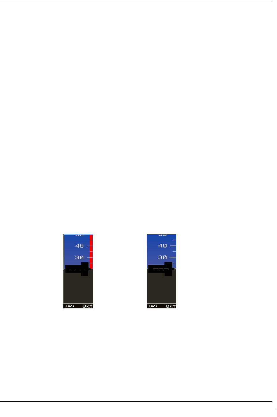
G1000/GFC700 System Maintenance Manual – C90A/C90GT/C90GTi King Air Page 7-53
190-00682-01 Revision G
7.22 Weight on Wheels and Low Speed Awareness Band Test
This check is accomplished to verify the integrity of the wiring interface between the right landing gear
safety switch assembly and the No. 1 and No. 2 GIA inputs (Discrete IN* 2A).
1. Ensure aircraft is positioned with weight on wheels.
2. Apply external power to the aircraft. Set BAT and AVIONICS MASTER switches to ON and
wait for all aircraft and avionics systems to complete their initialization and begin operating
normally.
3. Check that the airspeed fields are valid within 2 minutes of power up on both PFD1 and PFD2.
4. Verify the Low Speed Awareness Band is NOT displayed in the airspeed field on PFD1 and
PFD2 airspeed tapes (See Figure 7-9).
NOTE
This portion of the check can be accomplished in conjunction with the Landing Gear Aural Alert and XM
Audio Suppression Test in Section 7.2.2.
5. Place the airplane on jacks (Ref. Maintenance Manual Chapter 7-00-00) with the wheels clear of
the ground.
6. Verify the Low Speed Awareness Band (red band) at the low end of the airspeed tape on PFD1
and PFD2 (See Figure 7-9).
7. Remove airplane from jacks.
If no other service is to be performed, continue to the return-to-service checks in Section 8.
Figure 7-9. Low Speed Awareness Band Symbolization

Page 7-54 G1000/GFC700 System Maintenance Manual – C90A/C90GT/C90GTi King Air
Revision G 190-00682-01
7.23 ESP Functional Check
NOTE
This
procedure is required only for aircraft with the optional Electronic Stability
and Protection (ESP) feature.
1. Apply power to the aircraft and avionics systems by setting the BAT, EXT PWR and AVIONICS
MASTER PWR switches to ON. Ensure G1000 system and components are powered and
operating normally.
2. Verify the DISPLAY BACKUP button on the audio panel is pushed in so that the GDUs will not
operate in reversionary mode.
3. Verify no AHRS, ADC, Autopilot, PFD, AFCS Mode Controller, GCU alert messages or monitor
flags (HDG MISCOMP etc) are present on PFD1 or PFD2.
4. On initial power up verify that the MFD splash screen includes the following graphic:
5. On the GMC 710 couple the Flight Director to the left side by pressing the XFR button. The
arrow that is illuminated indicates which side is coupled. No flight director modes should be
active at this time.
6. On the GCU, rotate the inner FMS knob to activate the AUX – SYSTEM SETUP page on the
MFD.
7. On the MFD AUX – SYSTEM SETUP page press the SETUP 2 softkey.
8. Verify that on the MFD SETUP 2 page there is a window for Stability & Protection and the status
is “ENABLED”.
9. Verify on PFD 1 and PFD 2 that there are no “ESP FAIL”, “ESP OFF”, or “ESP DEGRADE”
alert messages.
10. Cover both GPS1 and GPS2 antennas.
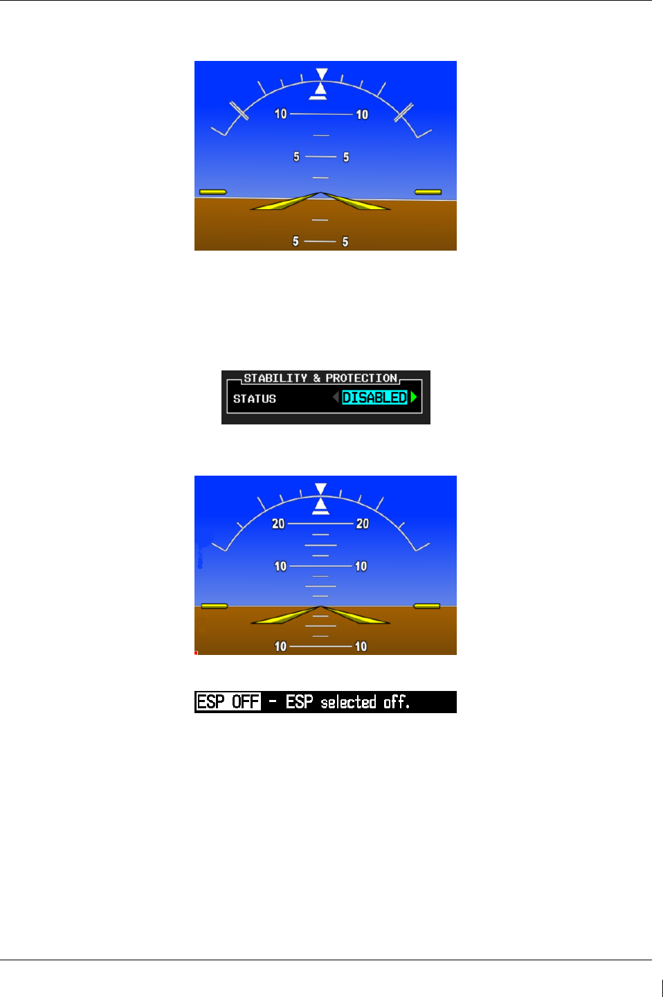
G1000/GFC700 System Maintenance Manual – C90A/C90GT/C90GTi King Air Page 7-55
190-00682-01 Revision G
11. Verify on PFD 1 and PFD 2 the ESP Roll Indices are displayed at 45° on the roll indicator on the
Attitude Display.
12. On the GCU, press the inner FMS knob to activate the cursor then rotate the outer FMS knob to
select the Stability & Protection window on the MFD.
13. Rotate the inner FMS knob to change the status to “DISABLED”.
14. Verify that on the MFD SETUP 2 page Stability & Protection window that the status is
“DISABLED”.
15. Verify on PFD 1 and PFD 2 the ESP Roll Indices are not displayed at 45° on the roll indicator on
the Attitude Display.
16. Verify on PFD 1 and PFD 2 that there is an “ESP OFF” alert message.
17. Remove the cover from both GPS1 and GPS2 antennas.
18. Remove power to the aircraft and avionics systems by placing the aircraft AVIONICS MASTER
PWR and EXP PWR switches to OFF.
19. Wait ~ 1 minute before re-applying aircraft power.
20. Apply power to the aircraft and avionics systems by setting the BAT, EXT PWR and AVIONICS
MASTER PWR switches to ON.
21. During power up and GPS satellite acquisition, verify on PFD1 and PFD2 the ESP Roll Indices
are displayed at 45° on the roll indicator on the Attitude Display.
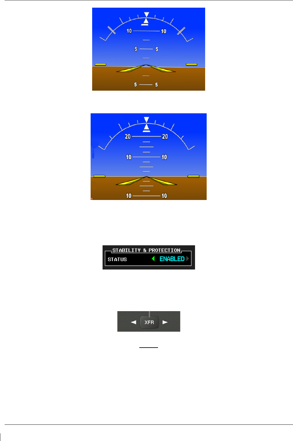
Page 7-56 G1000/GFC700 System Maintenance Manual – C90A/C90GT/C90GTi King Air
Revision G 190-00682-01
22. Once AFCS PFT is complete and GPS has acquired satellites, verify on PFD1 and PFD2 the ESP
Roll Indices are not displayed at 45° on the roll indicator on the Attitude Display.
23. On the GCU, rotate the inner FMS knob to activate the AUX – SYSTEM SETUP page.
24. On the MFD AUX – SYSTEM SETUP page press the SETUP 2 softkey.
25. Verify that on the MFD SETUP 2 page there is a window for Stability & Protection and the status
is “ENABLED”.
26. Verify on PFD 1 and PFD 2 that there are no “ESP FAIL” or “ESP OFF” alert messages.
27. On the GMC 710, couple the Flight Director to the right side by pressing the XFR button. The
arrow that is illuminated indicates which side is coupled. No flight director modes should be
active at this time.
NOTE
On power up the coupled side will default to the left side.
Each time power is
reapplied couple back to the right side and continue test steps.
28. Repeat step 1 thru 27 while coupled to right side.
29. Remove power to the aircraft and avionics systems by setting the aircraft AVIONICS MASTER
PWR, EXT PWR and BAT switches to OFF.
30.
Wait ~ 1 minute before re-applying power for further testing as required.

G1000/GFC700 System Maintenance Manual – C90A/C90GT/C90GTi King Air Page 8-1
190-00682-01 Revision G
8 System Return to Service Procedure
After reinstalling any G1000 LRU, verify the correct LRU software part numbers and versions against the
numbers listed on the General Arrangement drawing, listed in Table 1-2. To check an LRU software part
number and/or version, follow the procedure defined in Section 3.9.3.
IMPORTANT!
It is essential that the software versions be checked and matched against the listed
versions in the General Arrangement drawing listed in Table 1-2. Software
Configuration is a critical part of the G1000 operation and must be verified before
returning an aircraft to service.
Page 8-2 G1000/GFC700 System Maintenance Manual – C90A/C90GT/C90GTi King Air
Revision G 190-00682-01
8.1 Backup Path System Testing
This final checkout tests various secondary communications paths in the G1000 to ensure that the paths
function correctly. Additional aircraft systems checks are also performed in this section. Perform the
following steps and verify the results of each test.
8.1.1
GPS Failure Test
NOTE
Depending upon aircraft status and c
onfiguration, various other messages and
alerts may be present on GDUs during the failure tests.
Step
Desired Result
Single GPS Failure Conditions:
1. Ensure GPS satellites are acquired.
2. Place a shroud over the GPS antenna for
GIA 1 to prevent signal reception. Verify
loss of signal on MFD AUX page 4.
3. Check for desired results.
4. Remove shroud from the GIA 1 GPS
antenna and allow system to re-acquire
satellites.
5. Place a shroud over the GPS antenna for
GIA 2 to prevent signal reception. Verify
loss of signal on MFD AUX page 4.
6. Check for desired results.
7. Remove shroud from the GIA 2 GPS
antenna.
GPS Failure – For each of the specified GPS failure
conditions, the following shall remain valid on the
PFD throughout the procedure:
• Attitude and Heading from AHRS.
• Airspeed, Altitude, Vertical Speed, and OAT from
Air Data Computer.
• GPS Course Deviation Indicator remains valid on
PFD.
For a GIA1 GPS Failure, an amber BOTH ON
GPS2 is displayed on PFD 1 and PFD 2.
For a GIA2 GPS Failure, an amber BOTH ON
GPS1 is displayed on PFD 1 and PFD 2.
Dual GPS Failure Conditions:
1. Ensure GPS satellites are acquired.
2. Cover both GPS antennas. Verify loss of
signal on MFD AUX page 4.
3. Check for desired results.
4. Remove shrouds from GPS antennas.
5. Allow both receivers to re-acquire satellite
signals before continuing.
Dual GPS Failure - For a dual GPS failure, the
following shall occur:
• GPS CDI flags LOI on both PFDs.
• Attitude and Heading remain valid from both
AHRS on both PFDs.
• Airspeed, Altitude, Vertical Speed, and OAT
remain valid from both Air Data Computers on
both PFDs.
• No GPS Position appears on MFD Map.
• TAWS N/A aural alert & annunciation given.
When GPS satellites are re-acquired, verify that the
INTEG OK annunciation is given on the HSI in white
for a brief period of time then disappears.
After ~10 seconds of stable GPS position
reacquisition, verify the TAWS AVAILABLE aural
alert is given.
Verify that the system returns to normal navigation
mode (GPS CDI restored, DR annunciation
removed, & GPS data magenta).
G1000/GFC700 System Maintenance Manual – C90A/C90GT/C90GTi King Air Page 8-3
190-00682-01 Revision G
8.1.2
GIA Failure Test
Step
Desired Result
GIA 1 Failure Conditions:
1. Ensure GPS satellites are acquired.
2. Open GIA1 primary and secondary CBs.
3. Verify desired results.
4. Close GIA1 primary and secondary CBs.
Allow system to re-acquire satellites and
return to normal display modes.
• NAV 1 and COMM1 tuning fields on PFD1 and
PFD2 are invalid (red X).
• L/R engine data remains valid
• XPDR1 is Inoperative.
• GMA1 Is Inoperative.
• AHRS1 is using backup GPS source.
• AHRS2 not receiving backup GPS Information.
• An amber BOTH ON GPS2 is displayed on
PFD1 and PFD2.
• AHRS and ADC data remain valid on PFD1 and
PFD2.
GIA 2 Failure Conditions:
1. Open GIA 2 CB.
2. Verify desired results.
3. Close GIA 2 CB. Allow system to re-
acquire satellites and return to normal
display modes.
• NAV2 and COMM2 tuning fields on PFD1 and
PFD2 are invalid (red X).
• L/R engine data remains valid.
• XPDR2 is Inoperative.
• GMA2 Is Inoperative.
• AHRS2 is using backup GPS source.
• AHRS1 not receiving backup GPS Information.
• An amber BOTH ON GPS1 is displayed on
PFD1 and PFD2.
• AHRS and ADC data remain valid on PFD1 and
PFD2.
Dual GIA Failure Conditions:
1. Open GIA1 primary and secondary CBs
and GIA 2 CB.
2. Check for desired results.
3.
Restore power to both GIA units.
Dual GIA Failure – For a dual GIA failure, the
following shall occur:
• COM1/NAV1 & COM2/NAV2 fields flag invalid.
• GPS CDI flags DR on PFD
• NAV1 & NAV2 CDI loses deviation bar.
• XPDR field flags invalid on PFD.
• Engine Instrument field flags invalid on MFD.
• All AHRS & ADC fields remain valid.
• Red AFCS status annunciation given.
• TAWS FAIL annunciation given.*
• ADF/DME windows flag invalid.*
*If equipped.

Page 8-4 G1000/GFC700 System Maintenance Manual – C90A/C90GT/C90GTi King Air
Revision G 190-00682-01
8.1.3
Display Failure Test
Step
Desired Result
MFD Display Failure Conditions:
1. Open MFD CB.
2. Verify desired results.
3. Close MFD CB.
The following shall occur when power is removed
from the MFD:
• MFD goes blank.
• All PFD1 and 2 primary flight information is
retained.
• The COM 1/2 and NAV 1/2 tuning fields remain
valid and can be tuned by rotating the tuning
knobs on PFD1 and PFD2.
• XPDR 1/2 fields remain valid and XPDRs can
adjusted via PFD softkeys.
PFD2 Display Failure Conditions:
1. Open PFD 2 CB.
2. Verify desired results.
3. Close PFD 2 CB.
The following shall occur when power is removed
from PFD2:
• PFD2 goes blank.
• PFD1 and MFD remain in normal display formats.
The following illuminate on PFD1:
• HDG NO COMP illuminates on PFD1
• ROLL NO COMP illuminates on PFD1
• PIT NO COMP illuminates on PFD1
• IAS NO COMP illuminates on PFD1
• ALT NO COMP illuminates on PFD1
• GMA2 Fail – GMA2 is inoperative.
• XPDR2 Fail – XPDR2 is Inoperative.
PFD1 Display Failure Conditions:
1. Open PFD 1 PRI and PFD1 SEC circuit
breakers.
2. Verify desired results.
3. Close PFD 1 PRI and PFD1 SEC circuit
breakers.
The following shall occur when power is removed
from PFD1:
• PFD1 goes blank.
• PFD2 and MFD remain in normal display formats.
The following illuminate on PFD2:
• HDG NO COMP illuminates on PFD2
• ROLL NO COMP illuminates on PFD2
• PIT NO COMP illuminates on PFD2
• IAS NO COMP illuminates on PFD2
• ALT NO COMP illuminates on PFD2
• GMA1 Fail – GMA1 is inoperative.
• XPDR1 Fail – XPDR1 is Inoperative.

G1000/GFC700 System Maintenance Manual – C90A/C90GT/C90GTi King Air Page 8-5
190-00682-01 Revision G
8.1.4
G1000 Cooling Fan Fail Annunciation Check
Do the following to verify the cooling fans and annunciations are functioning properly
Step
Desired Result
Cooling Fan Failure Conditions:
1. Ensure the G1000 is in normal mode and
verify that there are no fan related alert
messages displayed in the PFD 1 or
PFD 2 Alerts Window.
2. Pull the following cooling fan circuit
breakers:
a) PFD/GIA FANS LEFT
b) PFD/GIA FANS RIGHT
c) MFD FAN
Verify that the following alert messages are
displayed:
• AVN FAN 1 FAIL – Avionics cooling fan #1 is
inoperative
• AVN FAN 2 FAIL – Avionics cooling fan #2 is
inoperative
• PFD 1 FAN FAIL – PFD #1 cooling fan is
inoperative
• PFD 2 FAN FAIL – PFD #2 cooling fan is
inoperative
• MFD FAN FAIL – MFD cooling fan is inoperative
Fan Failure reset and acknowledgement:
1. Reset all cooling fan circuit breakers.
2. Acknowledge alerts by pressing the
ALERTS softkey on PFD1.
Verify the above alerts extinguish.
8.1.5
Standby Instrument Electrical Power Checks
This section tests the standby electrical power for the standby attitude indicator, the standby altimeter and
the standby airspeed indicator. The magnetic compass is tested in each Phase inspection during the
cockpit lights check, (item 33 of the operational inspections) in the King Air Model 90 Series
Maintenance Manual, listed in Table 1-2.
Step
Desired Result
1. Remove or ensure external aircraft power
is removed. Set main battery switch to
OFF.
2. Ensure the STBY ATT and STBY ALTM
circuit breakers are closed.
3. Ensure the MASTER PANEL LIGHTS
rocker switch in the overhead panel is in
the ON position.
4. Ensure the STBY INSTR knob is turned to
full bright.
Verify the STANDBY BATTERY annunciator/switch
is not illuminated

Page 8-6 G1000/GFC700 System Maintenance Manual – C90A/C90GT/C90GTi King Air
Revision G 190-00682-01
Step
Desired Result
5. Select (depress) the STANDBY BATTERY
switch.
Verify the following:
• STBY Attitude indicator motor is energized as
indicated by the indicator motor and the absence
of flag.
• STBY altimeter vibrator is active as indicated by
vibrator noise.
• STBY attitude, STBY Altimeter, STBY Airspeed
indicators are illuminated full bright.
• Amber “ON” is annunciated full bright on the
STANDBY BATTERY switch.
• White STANDBY BATTERY legend on the
standby battery switch is illuminated full bright.
6. Activate aircraft power by selecting the
BAT switch ON.
7. Ensure that the generator busses are tied
by closing the GEN TIES MAN switch.
Verify the following:
• “ON” annunciation should extinguish on the
STANDBY BATTERY switch.
• “ARM” should be fully illuminated (green) on the
STANDBY BATTERY switch.
• The STBY attitude, STBY altimeter and STBY
airspeed instrument lighting reverts to the aircraft
settings.
• The STBY attitude motor and STBY altimeter
vibrator remain active.
• White STANDBY BATTERY legend on the
standby battery switch remains illuminated.
8. Deselect the STANDBY BATTERY switch Verify the following:
• “ARM” annunciation extinguishes on the
STANDBY BATTERY switch.
• STBY attitude motor and STBY altimeter vibrator
remain active.
• White STANDBY BATTERY legend on the
standby battery switch remains illuminated.
9. Remove aircraft power by selecting the
BAT switch to “OFF” position.
Verify the following:
• The STBY Attitude motor is deactivated (the
sound of the motor may be present as the gyro
spools down).
• The STBY altimeter vibrator is deactivated.
• The STBY attitude, STBY altimeter, STBY
airspeed and magnetic compass are no longer
illuminated.
• White STANDBY BATTERY legend on the
standby battery switch extinguishes.
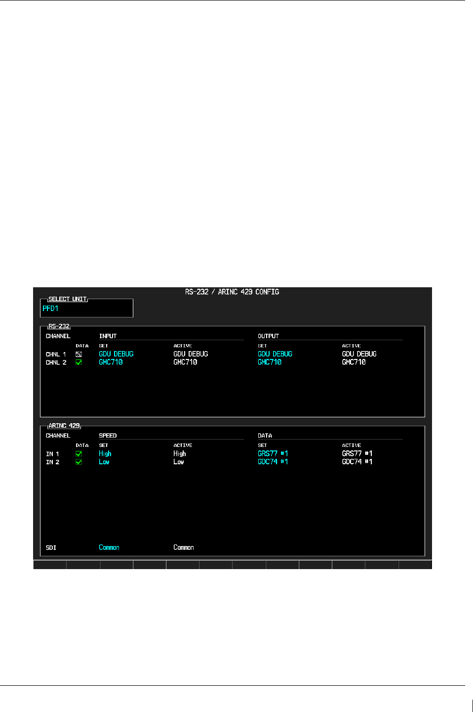
G1000/GFC700 System Maintenance Manual – C90A/C90GT/C90GTi King Air Page 8-7
190-00682-01 Revision G
8.1.6
G1000 Backup Path Test
1. Remove power from the displays by pulling the following circuit breakers:
a. PFD1 PRI
b. PFD1 SEC
c. PFD2
d. MFD
2. Individually power the PFD1, PFD2 and MFD by resetting the appropriate circuit breaker while
holding the ENT key on each display (far right key on MFD) until the words INITIALIZING
SYSTEM appear.
3. In configuration mode, go to the GDU Page Group on PFD1.
4. On PFD1, activate the cursor and select PFD1 in the SELECT UNIT field and press ENT.
5. Observe the GRS 77 and GDC 74 DATA indicators in the ARINC 429 window.
6. Verify both indicators are valid (GREEN √ ), indicating the channels are receiving data as shown
below:
NOTE
Reference Table 3-1 for interpretation of data indicator symbols
Figure 8-1. GDU Data Verification (ARINC 429)
7. On PFD1, activate the cursor and select PFD2 in the SELECT UNIT field and press the ENT key.
8. Repeat Steps 4 and 5.
9. On PFD1, activate the cursor and select MFD1 in the SELECT UNIT field and press the ENT
key.
10. Repeat Steps 4 and 5.
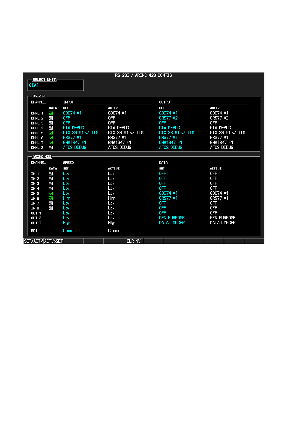
Page 8-8 G1000/GFC700 System Maintenance Manual – C90A/C90GT/C90GTi King Air
Revision G 190-00682-01
11. On PFD1, go to the GIA Page Group. Go to the RS-232 / ARINC 429 CONFIG page.
12. Verify that GIA1 is selected in the SELECT UNIT field.
13. Observe the data indicators for all configured RS-232 and ARINC 429 channels (except GIA
DEBUG), including the GRS 77 and GDC 74 ARINC 429 channels.
14. Verify all DATA indicators are valid (GREEN√ ), indicating the channels are receiving data as
shown in the following image:
Figure 8-2. GIA Data Verification (ARINC429/RS-232)
15. Activate the cursor and select GIA2 in the SELECT UNIT field, and then press the ENT key.
16. Repeat Steps 12 and 13.
17. On PFD1, go to the CAN / RS-485 CONFIGURATION page in the GIA Page Group.
18. Verify that GIA1 is selected in the SELECT UNIT field.
19. Observe the data indicators for all configured RS-485 channels.
20. Verify all DATA indicators are valid (GREEN√ ), indicating the channels are receiving data as
shown:
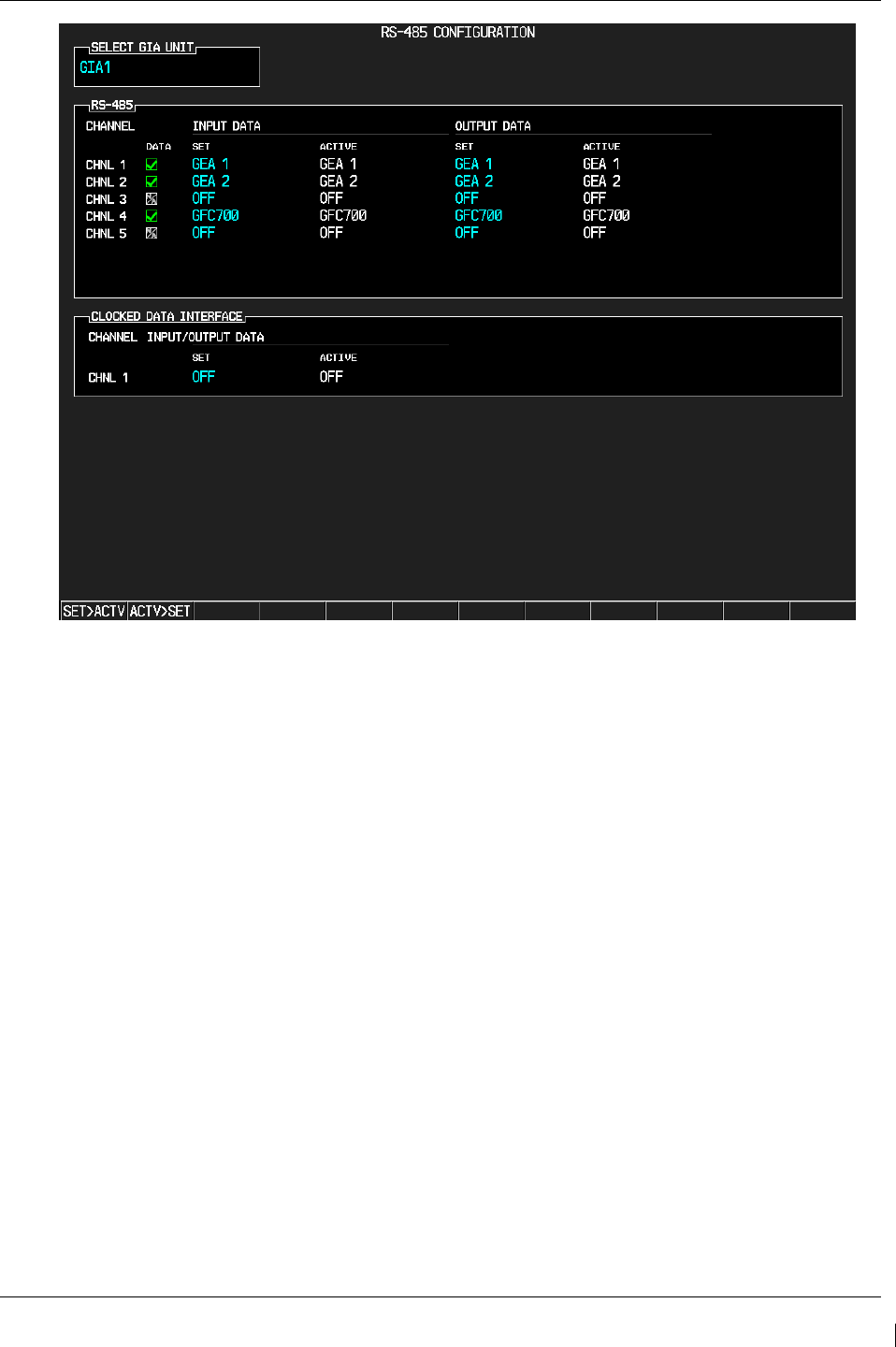
G1000/GFC700 System Maintenance Manual – C90A/C90GT/C90GTi King Air Page 8-9
190-00682-01 Revision G
Figure 8-3. GIA Data Verification (RS-485)
21. Activate the cursor and select GIA2 in the SELECT UNIT field, and then press the ENT key.
22. Repeat Steps 18 and 19.
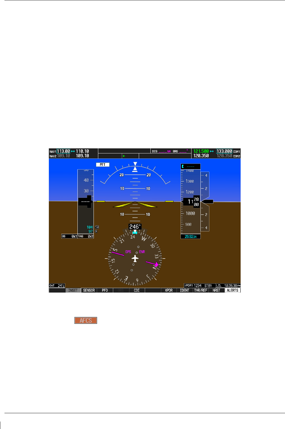
Page 8-10 G1000/GFC700 System Maintenance Manual – C90A/C90GT/C90GTi King Air
Revision G 190-00682-01
8.2 GFC 700 Ground Checkout
The following procedures verify the proper operation of the GFC 700 AFCS, after maintenance has been
performed. The technician performing these checks should be thoroughly familiar with the G1000 and
GFC 700. Information on the installation and operation of the GFC 700 can be found by referring to
Sections 6.11, 6.12 and the G1000 in King Air C90 Cockpit Reference Guide, listed in Table 1-2:
NOTE
In the sections that follow, an Autopilot disconnect should be accompanied by an aural
alert (two-second tone) unless otherwise specified.
8.2.1
Pre-Flight Test
1. If selected ON, select the AVIONICS MASTER switch and ground power unit to OFF. After 30
seconds select the ground power unit and AVIONICS MASTER switch to ON. Verify the GFC
700 begins an automatic pre-flight test after AHRS and ADC parameters become valid.
2. Verify that a white ‘PFT’ annunciation is displayed on PFD1 and PFD2, as shown in Figure 8-4
Figure 8-4. Pre-Flight Test
NOTE
A momentary red annunciation displayed before PFT starts is acceptable.
3. Upon successful completion of the test, an aural alert will sound and the annunciation will clear.
The aural alert is generated by either GIA 63W #1 or GIA 63W #2, alternately, with each system
power-up. Thus, the PFT sequence must be run twice to verify both GIA units are providing the
correct aural alert.
NOTE
If the ‘PFT’ annunciation turns red, the test has failed. Return to Section 5 for
troubleshooting.
4. Repeat Steps 1 - 3 to test the PFT aural alert for the other GIA 63W.
5. Continue to Section 8.2.2.

G1000/GFC700 System Maintenance Manual – C90A/C90GT/C90GTi King Air Page 8-11
190-00682-01 Revision G
8.2.2
AFCS Switch Checks
Verify that the AFCS system buttons and switches are operating correctly by performing the following:
1. Actuate both sections of the PITCH TRIM (NOSE UP/NOSE DN) switch to activate Manual
Electric Pitch Trim (MEPT). Verify the trim clutch engages and the trim wheel drives in the
requested direction. Check operation in both the up and down direction.
2. Press the AP/YD DISC TRIM INTRPT switch and hold while actuating the manual electric trim
switch. Verify trim does not run and the trim wheel rotates freely when moved manually.
Release the AP/YD DISC TRIM INTRPT button and PITCH TRIM switch.
3. Engage the autopilot by pressing the AP key on AFCS mode controller. Press and hold the left
section of the manual electric trim switch. Verify the Autopilot disengages normally with an
aural alert and the trim wheel rotates freely when moved manually.
4. Engage the autopilot again by pressing the AP key on the AFCS mode controller. Verify the
pitch and roll clutches engage and resist movement of the control wheel. Press and hold the CWS
switch and verify the control wheel moves freely when moved manually. Verify the green ‘AP’
at the top of PFD1 and PFD2 is replaced by a white ‘CWS’.
5. Release the CWS switch and press the ‘XFR’ key on the AFCS mode controller. Verify the
clutches are engaged and resist movement of the control wheel. Press and hold the CWS switch
and verify the control wheel moves freely when moved manually. Verify the green ‘AP’ at the
top of PFD1 and PFD2 is replaced by a white ‘CWS’.
6. Release the CWS switch and press the AP/YD DISC TRIM INTRPT switch on the pilots control
wheel. Verify the autopilot disengages with a flashing amber ‘AP’ annunciation on PFD1 and
PFD2, accompanied by an aural alert. Verify that the control wheel is free in pitch and roll axes.
7. Engage the autopilot again by pressing the ‘AP’ key on the AFCS mode controller. Open AFCS
SERVOS circuit breaker. Verify the autopilot disconnects and the abnormal disconnect is
provided, consisting of a continuous aural alert and a flashing red/white ‘AP’ annunciation.
Verify no AFCS annunciations (e.g. AFCS, PFT, Mistrim) remain on PFD1 or PFD2. Press the
AP/YD DISC TRIM INTRPT switch to cancel the abnormal alert. Close the AFCS SERVOS
circuit breaker to restore power to the system and wait for completion of the pre-flight test
sequence.
8. Engage the autopilot again by pressing the ‘AP’ key on the AFCS mode controller. Ensure the
autopilot is coupled to GIA1 by verifying the arrowhead next to the ‘XFR’ key on the AFCS
mode controller is pointing to the pilot’s side. If the arrowhead points to the copilot’s side, press
the ‘XFR’ key. Open GIA1 primary and secondary circuit breakers. Verify the autopilot
disconnects with a continuous aural alert and a flashing red/white ‘AP’ annunciation. Press the
AP/YD DISC TRIM INTRPT switch to cancel the alert and annunciation. Close the GIA1
primary and secondary circuit breakers and wait for completion of the pre-flight test sequence.
9. Press the ‘XFR’ key on the AFCS mode controller and engage the autopilot by pressing the ‘AP’
key on the AFCS Mode Controller. Press the AP/YD DISC TRIM INTRPT switch on the pilot
side to disconnect the autopilot; verify the flashing amber ‘AP’ alert is displayed on PFD1 & 2.
10. Press the GO AROUND button on the left throttle. Verify ‘TO’ is annunciated on PFD1 and
PFD2 for both PITCH and ROLL modes and the command bars should be at 8 degrees nose up
and wings-level.
11. Press the Flight Director (FD) key on the AFCS mode controller to deactivate the GA mode.
Press the AP key to engage the autopilot. Press the CWS button for a minimum of 5 seconds and
release; verifying there is no residual force on the control stick for the pitch axis.
12. Disengage the autopilot by pressing the AP/YD DISC TRIM INTRPT switch on the co-pilot’s
control wheel. Engage VS mode by pressing the VS key on the AFCS mode controller. Verify
PFD1 and PFD2 display ‘VS’ in green and indicates a pitch reference of ‘0 FPM’.

Page 8-12 G1000/GFC700 System Maintenance Manual – C90A/C90GT/C90GTi King Air
Revision G 190-00682-01
13. Press the FLC key on the AFCS mode controller and verify that ‘FLC’ is annunciated on PFD1
and PFD2 in green with a reference of 100 KTS.
14. Press the ALT SEL key on the AFCS mode controller and verify that the ‘ALT’ annunciation is
displayed in green on PFD1 and PFD2 with an altitude reference equal to the aircraft altitude
(within the nearest 20 feet).
15. Press the FD key and verify that the mode annunciations and command bars are removed from
the display.
8.2.3
Autopilot Clutch Overpower Check
NOTE
The GFC 700 uses electronic torque limiting as well as mechanical slip clutches to limit
the maximum servo effort. When the system is on the ground, the electronic torque
limiting is removed, allowing manual checks of the slip-clutch settings.
1. Engage the Autopilot by pressing the AP key on the AFCS mode controller.
2. Manually overpower the autopilot clutches in pitch and roll. If the Autopilot clutches cannot be
overpowered, check the servo clutch torque settings. For the GSM 86, if the GSM86 clutch
cannot be overpowered, check the GSM 86 clutch cartridge. Refer to the servo installation
drawing (listed in Table 1-2) as applicable.
3. Actuate and hold PITCH TRIM switch in either the NOSE UP or NOSE DOWN direction to
disconnect the autopilot. While the trim is running, restrain the aircraft pitch trim wheel and
verify that the trim clutch can be overpowered. If it cannot be overpowered, check the trim servo
clutch torque setting. For the GSM 86, if the GSM86 clutch cannot be overpowered, check the
GSM 86 clutch cartridge. Refer to the pitch trim servo installation drawing, listed in Table 1-2.
4. Engage the autopilot by pressing the AP key on the AFCS mode controller. Actuate and hold the
manual electric trim switch in either the up or down direction to disconnect the autopilot. Verify
that the trim wheel moves smoothly in both directions throughout the entire trim range during
manual electric trim operation. If the trim wheel hesitates, this may indicate that the pitch trim
clutch is slipping and proper clutch setting and cable tension should be verified. Refer to the
King Air Model 90 Series Maintenance Manual and Pitch Trim Servo Install drawing, listed in
Table 1-2, for clutch settings and cable tensions. If both clutch setting and cable tension are
within tolerance, check the aircraft pitch trim system for excessive friction. Refer to the
appropriate C90 Maintenance Manual, listed in Table 1-2.
8.2.4
Manual Electric Pitch Trim Speed Check
1. Run MANUAL ELECTRIC PITCH TRIM in one direction until it runs against the mechanical
stop.
2. Run the trim in the opposite direction, and using a stop watch or equivalent device, time the trim
speed to the opposite mechanical stop. Verify the elapsed time for full travel measures 15 ± 5
seconds.
8.2.5
Autopilot Operation Checks
1. Engage the Autopilot by pressing the AP key on the AFCS mode controller. Push the HDG knob
to synchronize the heading bug to the current aircraft heading. Select HDG mode by pressing the
HDG key on the AFCS mode controller. Verify the command bars are level and the control wheel
is stationary. (There may be some roll motion in the yoke if the aircraft not perfectly level.)

G1000/GFC700 System Maintenance Manual – C90A/C90GT/C90GTi King Air Page 8-13
190-00682-01 Revision G
2. Turn the HDG knob to the left and right and check that the command bars move in the correct
direction and the control wheel follows the command bars.
3. Push and hold the CWS button and pull the control wheel to the center of the pitch control range.
Release the CWS button. Verify the autopilot clutches re-engage and hold the wheel stationary.
4. Holding the control wheel lightly, rotate the NOSE UP/DN wheel on the AFCS mode controller
two clicks, to increase the pitch reference. Verify the command bars move up 1 degree and the
control wheel begins moving aft. (In some aircraft, the down spring may require manual
assistance to get aft control stick movement).
5. While holding the control wheel firmly, press and hold the CWS button to re-synchronize the
pitch reference. Re-center the control wheel to wings level and mid-range elevator travel.
Release the CWS button and check that servo clutches re-engage before releasing the control
wheel.
6. Rotate the NOSE UP/DN wheel on the AFCS mode controller two clicks. Verify the command
bars command a pitch attitude 2 degrees lower and the control wheel begins moving forward.
Hold the controls and press CWS to re-center the command bars and stop control wheel
movement.
7. With the Autopilot still engaged and the CWS button pressed, move the control wheel to its aft
limit. Release the CWS button and apply continuous forward pressure, slowly moving the control
wheel. After a brief delay, verify the trim wheel begins moving in a trim up direction.
8. Grip the control wheel and press the CWS button. Verify trim motion stops. Move the control
wheel to the forward limit and release the CWS button. Slowly move the control wheel aft. After
a brief delay, verify the trim wheel begins to trim down. Relieve pressure on the wheel and verify
the trim motion stops. Check that the trim wheel is free to turn. Hold the control wheel and press
the AP/YD DISC TRIM INTRPT switch to disconnect the autopilot.
8.2.6
VOR/LOC/GS Test
Perform the following test using ramp test equipment. Operate the equipment according to the test
equipment manufacturer’s instructions.
NOTE
The PFD HSI does not show a course deviation bar unless a valid VHF NAV frequency
is tuned.
1. Ensure FD is coupled to PFD1 as indicated by a left pointing arrow next to the XFR button.
2. Simulate a VOR signal on a radial equivalent to the aircraft heading. Tune the NAV 1 and NAV 2
receivers to the simulation frequency.
3. Set the HSI on PFD1 to VOR1 by pressing the CDI soft key until VOR1 is selected. Set the HSI
on PFD2 to VOR2 by pressing the CDI soft key until VOR2 is selected. Rotate CRS1 and CRS2
knobs to set VOR1 and VOR2 course pointers to aircraft heading. (CDI Synchronization must be
set to OFF on the AUX-SYSTEM SETUP 1 page on the MFD.)
4. Verify full scale deflection of VOR1 and VOR2 CDI by varying the selected course at least 10°
left and right. Reset course pointers to aircraft heading.
5. Engage the autopilot and press the NAV key on the AFCS mode controller. Using the CRS1 knob
alter course by 10° to the right. Verify the flight director and aircraft controls respond by flying
to the VOR course. Repeat to the left.

Page 8-14 G1000/GFC700 System Maintenance Manual – C90A/C90GT/C90GTi King Air
Revision G 190-00682-01
6. Couple FD to PFD2 by pressing the XFR button on the AFCS mode controller. Verify FD is
coupled right as indicate by a right pointing arrow on the AFCS mode controller next to the XFR
button. Repeat step 5 using CRS2 knob while coupled to PFD2.
7. Set CRS1 and CRS2 course pointers to aircraft heading.
8. Simulate a Localizer/Glideslope signal. Tune this signal on NAV 1 and NAV 2 receiver. Set the
PFD1 HSI to LOC1 and PFD2 HSI to LOC2 by pressing CDI soft key until LOC1 and LOC2 is
selected. Use the test equipment to center the deviation bars (localizer and glideslope) on PFD1
and PFD2.
9. Press the APR key on the AFCS mode controller. Verify that the LOC and GS annunciations are
green on PFD1 and PFD2. Apply right/left and up/down localizer/glideslope signals using the
test equipment. Verify that the Flight Director and flight controls respond appropriately.
10. Couple FD to PFD1 by pressing the XFR button on the AFCS mode controller. Verify FD is
coupled to PFD1 as indicate by a left pointing arrow on the AFCS mode controller next to the
XFR button.
11. Repeat step 9 using while coupled to PFD1.
8.3 Maintenance Records
After conducting required return-to-service procedures in accordance with the King Air Model 90 Series
Maintenance Manual, listed in Table 1-2, the aircraft may be returned to service.
1. Record the following information in appropriate aircraft maintenance logs:
a. Part number of the G1000 software loader card used to perform software loading or
software updates.
b. Record part and serial numbers of any LRU which was replaced.
c. Record any database updates which were performed during maintenance.
d. Any other applicable information related to the maintenance work performed on the
aircraft.
