Garmin Mdl Rev 16 Sa01535Wi D
2015-05-27
: Garmin Garmin-Mdl-Rev-16-Sa01535Wi-D-720657 garmin-mdl-rev-16-sa01535wi-d-720657 garmin pdf
Open the PDF directly: View PDF ![]() .
.
Page Count: 734 [warning: Documents this large are best viewed by clicking the View PDF Link!]
- Section 1 System Overview
- Section 2 Flight Instruments
- Section 3 Engine Indication System
- Section 4 Audio Panel and CNS
- Section 5 Flight Management
- 5.1 Introduction
- 5.2 Using Map Displays
- 5.3 Waypoints
- 5.4 Airspaces
- 5.5 Direct-to-Navigation
- 5.6 Flight Planning
- Flight Plan Creation
- Adding Waypoints to an Existing Flight Plan
- Adding Airways to a Flight Plan
- Adding Procedures to a Stored Flight Plan
- Flight Plan Storage
- Flight Plan Editing
- Along Track Offsets
- Parallel Track
- Activating a Flight Plan Leg
- Inverting a Flight Plan
- Flight Plan Views
- Closest Point of FPL
- User-Defined Holding Patterns
- 5.7 Vertical Navigation
- 5.8 Procedures
- 5.9 Trip Planning
- 5.10 RAIM Prediction
- 5.11 Navigating a Flight Plan
- 5.12 Abnormal Operation
- Section 6 Hazard Avoidance
- Section 7 Automatic Flight Control System
- Section 8 Additional Features
- Appendices
- Index

Beechcraft 200/B200 Series
G1000®Integrated Flight Deck
Pilot’s Guide

190-00928-04 Rev. A
Garmin G1000 Pilot’s Guide for the Beechcraft 200/B200 Series
Copyright © 2008-2013 Garmin Ltd. or its subsidiaries. All rights reserved.
This manual reflects the operation of System Software version 0985.07 or later for the Beechcraft 200/B200 Series. Some differences in
operation may be observed when comparing the information in this manual to earlier or later software versions.
Garmin International, Inc., 1200 East 151st Street, Olathe, Kansas 66062, U.S.A.
Tel: 913/397.8200 Fax: 913/397.8282
Garmin AT, Inc., 2345 Turner Road SE, Salem, OR 97302, U.S.A.
Tel: 503/391.3411 Fax: 503/364.2138
Garmin (Europe) Ltd., Liberty House, Hounsdown Business Park, Southampton, Hampshire SO40 9LR U.K.
Tel: 44 (0) 23 8052 4000 Fax: 44 (0) 23 8052 4004 Aviation Support:44 (0) 87 0850 1243
Garmin Corporation, No. 68, Jangshu 2nd Road, Shijr, Taipei County, Taiwan
Tel: 886/02.2642.9199 Fax: 886/02.2642.9099
For after-hours emergency, aircraft on ground (AOG) technical support for Garmin panel mount and integrated avionics systems, please
contact Garmin’s AOG Hotline at 913.397.0836.
Website Address: www.garmin.com
Except as expressly provided herein, no part of this manual may be reproduced, copied, transmitted, disseminated, downloaded or stored
in any storage medium, for any purpose without the express written permission of Garmin. Garmin hereby grants permission to download
a single copy of this manual and of any revision to this manual onto a hard drive or other electronic storage medium to be viewed for
personal use, provided that such electronic or printed copy of this manual or revision must contain the complete text of this copyright notice
and provided further that any unauthorized commercial distribution of this manual or any revision hereto is strictly prohibited.
Garmin® and G1000® are registered trademarks of Garmin Ltd. or its subsidiaries, and ESP™ is a trademark of Garmin Ltd. or its subsidiaries.
These trademarks may not be used without the express permission of Garmin.
Bendix/King® and Honeywell® are registered trademarks of Honeywell International, Inc.; Becker® is a registered trademark of Becker
Flugfunkwerk GmbH; NavData® is a registered trademark of Jeppesen, Inc.
AOPA Membership Publications, Inc. and its related organizations (hereinafter collectively “AOPA”) expressly disclaim all warranties,
with respect to the AOPA information included in this data, express or implied, including, but not limited to, the implied warranties
of merchantability and fitness for a particular purpose. The information is provided “as is” and AOPA does not warrant or make any
representations regarding its accuracy, reliability, or otherwise. Under no circumstances including negligence, shall AOPA be liable for any
incidental, special or consequential damages that result from the use or inability to use the software or related documentation, even if
AOPA or an AOPA authorized representative has been advised of the possibility of such damages. User agrees not to sue AOPA and, to
the maximum extent allowed by law, to release and hold harmless AOPA from any causes of action, claims or losses related to any actual
or alleged inaccuracies in the information. Some jurisdictions do not allow the limitation or exclusion of implied warranties or liability for
incidental or consequential damages so the above limitations or exclusions may not apply to you.
AC-U-KWIK and its related organizations (hereafter collectively “AC-U-KWIK Organizations”) expressly disclaim all warranties with
respect to the AC-U-KWIK information included in this data, express or implied, including, but not limited to, the implied warranties of
merchantability and fitness for a particular purpose. The information is provided “as is” and AC-U-KWIK Organizations do not warrant or
make any representations regarding its accuracy, reliability, or otherwise. Licensee agrees not to sue AC-U-KWIK Organizations and, to the
maximum extent allowed by law, to release and hold harmless AC-U-KWIK Organizations from any cause of action, claims or losses related
to any actual or alleged inaccuracies in the information arising out of Garmin’s use of the information in the datasets. Some jurisdictions
do not allow the limitation or exclusion of implied warranties or liability for incidental or consequential damages so the above limitations
or exclusions may not apply to licensee.
December 2013 Printed in the U.S.A.

Garmin G1000 Pilot’s Guide for the Beechcraft 200/B200 Series
190-00928-04 Rev. Aii
LIMITED WARRANTY
LIMITED WARRANTY
Within the warranty period, Garmin will, at its sole discretion, repair or replace any components that fail in normal use. Such repairs or
replacement will be made at no charge to the customer for parts and/or labor incidental to the direct repair of said product. Garmin may,
at its discretion with prior approval, reimburse an authorized Garmin Service Center for associated labor costs incurred for removal and
replacement of the panel mount product installed in an aircraft. The customer shall be responsible for any transportation or other cost. This
warranty does not apply to: (i) cosmetic damage, such as scratches, nicks and dents; (ii) consumable parts, such as batteries, unless product
damage has occurred due to a defect in materials or workmanship; (iii) damage caused by accident, abuse, misuse, water, flood, fire, or
other acts of nature or external causes; (iv) damage caused by service performed by anyone who is not an authorized service provider
of Garmin; or (v) damage to a product that has been modified or altered without the written permission of Garmin. In addition, Garmin
reserves the right to refuse warranty claims against products or services that are obtained and/or used in contravention of the laws of any
country.
THE WARRANTIES AND REMEDIES CONTAINED HEREIN ARE EXCLUSIVE AND IN LIEU OF ALL OTHER WARRANTIES, WHETHER EXPRESS,
IMPLIED OR STATUTORY, INCLUDING ANY LIABILITY ARISING UNDER ANY WARRANTY OF MERCHANTABILITY OR FITNESS FOR A
PARTICULAR PURPOSE, STATUTORY OR OTHERWISE. THIS WARRANTY GIVES YOU SPECIFIC LEGAL RIGHTS, WHICH MAY VARY FROM
STATE TO STATE.
IN NO EVENT SHALL GARMIN BE LIABLE FOR ANY INCIDENTAL, SPECIAL, INDIRECT OR CONSEQUENTIAL DAMAGES, WHETHER
RESULTING FROM THE USE, MISUSE, OR INABILITY TO USE THIS PRODUCT OR FROM DEFECTS IN THE PRODUCT. Some states do not
allow the exclusion of incidental or consequential damages, so the above limitations may not apply in every case.
Garmin retains the exclusive right to repair or replace (with a new or newly-overhauled replacement product) the product or offer a full
refund of the purchase price at its sole discretion. SUCH REMEDY SHALL BE YOUR SOLE AND EXCLUSIVE REMEDY FOR ANY BREACH OF
WARRANTY.
To obtain warranty service, contact your local Garmin Authorized Service Center. For assistance in locating the nearest Service Center, call
Garmin Customer Service at one of the numbers listed below.
Products sold through online auctions are not eligible for warranty coverage or rebates or other special offers from Garmin. Online auction
confirmations are not accepted for warranty verification. To obtain warranty service, an original or copy of the sales receipt from the original
retailer is required. Garmin will not replace missing components from any package purchased through an online auction.
Garmin International Inc.
1200 East 151st Street, Olathe, Kansas 66062
Telephone: (913)397-8200
Telephone Toll Free: (888)606-5482
Facsimile: (913)397-8282
Facsimile Toll Free: (800)801-4670
E-mail: orders@garmin.com
avionics@garmin.com
warranty@garmin.com
Garmin (Europe) Ltd.
Liberty House, Bulls Copse Road, Southampton, SO40
9RB, UK
Telephone: ++44 (0) 870-8501243
Telephone Toll Free: ++44 (0) 0808 238 0000
(option 5)
Facsimile: ++44 (0) 238052004
E-mail: avionics.europe@garmin.com
190-00928-04 Rev. A
Garmin G1000 Pilot’s Guide for the Beechcraft 200/B200 Series
iii
WARNINGS, CAUTIONS, AND NOTES
WARNING: Navigation and terrain separation must NOT be predicated upon the use of the terrain avoidance
feature. The terrain avoidance feature is NOT intended to be used as a primary reference for terrain avoidance
and does not relieve the pilot from the responsibility of being aware of surroundings during flight. The
terrain avoidance feature is only to be used as an aid for terrain avoidance. Terrain data is obtained from
third party sources. Garmin is not able to independently verify the accuracy of the terrain data.
WARNING: The displayed minimum safe altitudes (MSAs) are only advisory in nature and should not be
relied upon as the sole source of obstacle and terrain avoidance information. Always refer to current
aeronautical charts for appropriate minimum clearance altitudes.
WARNING: The altitude calculated by G1000 GPS receivers is geometric height above Mean Sea Level and
could vary significantly from the altitude displayed by pressure altimeters, such as the GDC 74 Air Data
Computer, or other altimeters in aircraft. GPS altitude should never be used for vertical navigation. Always
use pressure altitude displayed by the G1000 PFD or other pressure altimeters in aircraft.
WARNING: Do not use outdated database information. Databases used in the G1000 system must be updated
regularly in order to ensure that the information remains current. Pilots using any outdated database do so
entirely at their own risk.
WARNING: Do not use basemap (land and water data) information for primary navigation. Basemap data is
intended only to supplement other approved navigation data sources and should be considered as an aid to
enhance situational awareness.
WARNING: Do not rely solely upon the display of traffic information for collision avoidance maneuvering.
The traffic display does not provide collision avoidance resolution advisories and does not under any
circumstances or conditions relieve the pilot’s responsibility to see and avoid other aircraft.
WARNING: Do not rely solely upon the display of traffic information to accurately depict all of the traffic
within range of the aircraft. Due to lack of equipment, poor signal reception, and/or inaccurate information
from aircraft or ground stations, traffic may be present that is not represented on the display.
WARNING: Do not rely on information from a lightning detection system display as the sole basis for hazardous
weather avoidance. Range limitations and interference may cause the system to display inaccurate or
incomplete information. Refer to documentation from the lightning detection system manufacturer for
detailed information about the system.
WARNING: Do not use data link weather information for maneuvering in, near, or around areas of hazardous
weather. Information contained within data link weather products may not accurately depict current
weather conditions.
WARNING: Do not use the indicated data link weather product age to determine the age of the weather
information shown by the data link weather product. Due to time delays inherent in gathering and processing
weather data for data link transmission, the weather information shown by the data link weather product
may be significantly older than the indicated weather product age.

Garmin G1000 Pilot’s Guide for the Beechcraft 200/B200 Series
190-00928-04 Rev. Aiv
WARNINGS, CAUTIONS, AND NOTES
WARNING:
For safety reasons, G1000 operational procedures must be learned on the ground.
WARNING:
The Garmin system, as installed in this aircraft, has a very high degree of functional integrity.
However, the pilot must recognize that providing monitoring and/or self-test capability for all conceivable
system failures is not practical.
WARNING:
The United States government operates the Global Positioning System and is solely responsible
for its accuracy and maintenance. The GPS system is subject to changes which could affect the accuracy
and performance of all GPS equipment. Portions of the Garmin G1000 utilize GPS as a precision electronic
NAVigation AID (NAVAID). Therefore, as with all NAVAIDs, information presented by the G1000 can be
misused or misinterpreted and, therefore, become unsafe.
WARNING:
To reduce the risk of unsafe operation, carefully review and understand all aspects of the G1000
Pilot’s Guide documentation and the G1000 Integrated Avionics System in the Airplane Flight Manual.
Thoroughly practice basic operation prior to actual use. During flight operations, carefully compare indications
from the G1000 to all available navigation sources, including the information from other NAVAIDs, visual
sightings, charts, etc. For safety purposes, always resolve any discrepancies before continuing navigation.
WARNING: Do not use the system to attempt to penetrate a thunderstorm. The illustrations in this guide are
only examples. Both the FAA Advisory Circular, Subject: Thunderstorms, and the Aeronautical Information
Manual (AIM) recommend avoiding any thunderstorm identified as severe of giving intense radar echo by
at least 20 miles.
WARNING
:
Lamp(s) inside this product may contain mercury (HG) and must be recycled or disposed of
according to local, state, or federal laws. For more information, refer to our website at www.garmin.com/
aboutGarmin/environment/disposal.jsp.
WARNING
:
Because of variation in the earth’s magnetic field, operating the system within the following
areas could result in loss of reliable attitude and heading indications (GRS 77 installations only). North
of 72° North latitude at all longitudes; South of 70° South latitude at all longitudes; North of 65° North
latitude between longitude 75° W and 120° W. (Northern Canada); North of 70° North latitude between
longitude 70° W and 128° W. (Northern Canada); North of 70° North latitude between longitude 85° E and
114° E. (Northern Russia); South of 55° South latitude between longitude 120° E and 165° E. (Region south
of Australia and New Zealand)
WARNING
:
Do not use GPS to navigate to any active waypoint identified as a ‘NON WGS84 WPT’ by a
system message. ‘NON WGS84 WPT’ waypoints are derived from an unknown map reference datum that
may be incompatible with the map reference datum used by GPS (known as WGS84) and may be positioned
in error as displayed.
190-00928-04 Rev. A
Garmin G1000 Pilot’s Guide for the Beechcraft 200/B200 Series
v
WARNINGS, CAUTIONS, AND NOTES
CAUTION: The PFD and MFD displays use a lens coated with a special anti-reflective coating that is very
sensitive to skin oils, waxes, and abrasive cleaners. CLEANERS CONTAINING AMMONIA WILL HARM THE
ANTI-REFLECTIVE COATING. It is very important to clean the lens using a clean, lint-free cloth and an
eyeglass lens cleaner that is specified as safe for anti-reflective coatings.
CAUTION:
The Garmin G1000 does not contain any user-serviceable parts. Repairs should only be made by
an authorized Garmin service center. Unauthorized repairs or modifications could void both the warranty
and the pilot’s authority to operate this device under FAA/FCC regulations.
NOTE: When using Stormscope, there are several atmospheric phenomena in addition to nearby
thunderstorms that can cause isolated discharge points in the strike display mode. However, clusters of
two or more discharge points in the strike display mode do indicate thunderstorm activity if these points
reappear after the screen has been cleared.
NOTE: Do not rely solely upon data link services to provide Temporary Flight Restriction (TFR) information.
Always confirm TFR information through official sources such as Flight Service Stations or Air Traffic Control.
NOTE: All visual depictions contained within this document, including screen images of the G1000 panel and
displays, are subject to change and may not reflect the most current G1000 system and aviation databases.
Depictions of equipment may differ slightly from the actual equipment.
NOTE
: This device complies with part 15 of the FCC Rules. Operation is subject to the following two
conditions: (1) this device may not cause harmful interference, and (2) this device must accept any
interference received, including interference that may cause undesired operation.
NOTE
: Interference from GPS repeaters operating inside nearby hangars can cause an intermittent loss of
attitude and heading displays while the aircraft is on the ground. Moving the aircraft more than 100 yards
away from the source of the interference should alleviate the condition.
NOTE
: Use of polarized eyewear may cause the flight displays to appear dim or blank.
NOTE
: This product, its packaging, and its components contain chemicals known to the State of California
to cause cancer, birth defects, or reproductive harm. This notice is being provided in accordance with
California’s Proposition 65. If you have any questions or would like additional information, please refer to
our web site at www.garmin.com/prop65.
NOTE
: When operating the G1000 in DG Free Mode (GRS 7800 installations only), the heading information
used by some system components (e.g. GTS 8000, AFCS, and GWX) will be different from the heading
displayed on the GDU by an amount equal to the difference between the current Magnetic Field Variation
Database (MV DB) value, and the MV DB value when DG Free Mode was activated. Due to the convergence
of isogonic lines, this condition is most noticeable at or near the North and South poles.

Garmin G1000 Pilot’s Guide for the Beechcraft 200/B200 Series
190-00928-04 Rev. Avi
WARNINGS, CAUTIONS, AND NOTES
NOTE
: System navigation utilities may not reliably calculate range and bearing information when the
aircraft is operating north of 80° North latitude or south of 80° South latitude. This may result in the system
displaying small gaps in racetrack holding pattern depictions (GRS 7800 installations only).
NOTE
: The Terrain Awareness and Warning System (TAWS) may not operate reliably north of 89º North
latitude and south of 89º South latitude. This is due to limitations present within the Terrain database and
the system’s ability to process the data representing the affected areas (GRS 7800 installations only).

190-00928-04 Rev. A
Garmin G1000 Pilot’s Guide for the Beechcraft 200/B200 Series
vii
REVISION INFORMATION
Record of Revisions
Part Number Revision Date Page Range Description
190-00928-00 A 12/3/08 i – I-6 Initial Release for GDU 9.12
190-00928-01 A 7/24/09 i – I-6 Added GDU 10.00 changes
Added TAWS A functionality
Added radar altimeter functionality
190-00928-02 A 10/20/10 i – I-6 Added GDU 11.12 changes
Added GTS 820/850
Added GDL 59/GSR 56
Added Worldwide Weather
Added Profile View
Added Selected Altitude Arc
Added Electronic Stabilization & Protection (ESP™)
190-00928-03 A 8/30/11 i – I-6 Added GDU 12.01 changes
Added EGNOS
Added WX LGND Softkey on PFD
Removed DB SYNC Softkey
Changed Altitude to GSL Altitude on GPS Status Page
190-00928-04 A 12/02/13 i – I-6 Added GDU 13.04 changes, including User Defined Holds,
Temp Compensated Altitudes, Pilot Profile Import/Export, LP
approaches, and Baro VNAV approaches.
Added GDC 7400, GRS 7800, GTX 3000, GRA 5500, GTS 8000,
and GWX 70
Removed ADB TX Softkey
Removed GND Softkey (Transponder Mode)

Garmin G1000 Pilot’s Guide for the Beechcraft 200/B200 Series
190-00928-04 Rev. Aviii
TABLE OF CONTENTS
SECTION 1 SYSTEM OVERVIEW
1.1 System Description ................................................... 1
1.2 Line Replaceable Units (LRU) ................................... 2
1.3 G1000 Controls ......................................................... 5
PFD Controls ................................................................ 5
Controls Associated With the MFD ................................. 7
AFCS Controls .............................................................. 9
Audio Panel Controls .................................................. 11
1.4 Secure Digital Cards ............................................... 13
1.5 System Power-up ..................................................... 14
1.6 System Operation ................................................... 15
Normal Operation ....................................................... 15
Reversionary Mode ..................................................... 15
AHRS Operation ......................................................... 17
G1000 System Annunciations ...................................... 20
Softkey Function ......................................................... 20
GPS Receiver Operation .............................................. 29
1.7 Accessing G1000 Functionality ............................. 34
Menus ....................................................................... 34
MFD Page Groups ....................................................... 34
MFD System Pages...................................................... 38
1.8 Display Backlighting ............................................... 53
SECTION 2 FLIGHT INSTRUMENTS
2.1 Flight Instruments ................................................... 58
Airspeed Indicator ...................................................... 58
Attitude Indicator ....................................................... 61
Altimeter ................................................................... 63
Vertical Speed Indicator (VSI) ....................................... 66
Vertical Deviation ....................................................... 66
Horizontal Situation Indicator (HSI) .............................. 68
Course Deviation Indicator (CDI) .................................. 73
2.2 Supplemental Flight Data ...................................... 81
Temperature Displays .................................................. 81
Wind Data ................................................................. 82
Vertical Navigation (VNV) Indications ........................... 83
2.3 PFD Annunciations and Alerting Functions .......... 84
G1000 Alerting system ................................................ 84
Marker Beacon Annunciations...................................... 86
Traffic Annunciation .................................................... 86
TAWS Annunciations ................................................... 87
Altitude Alerting ......................................................... 87
Low Altitude Annunciation .......................................... 88
Minimum Descent Altitude/Decision Height Alerting ...... 88
Radar Altimeter .......................................................... 90
2.4 Abnormal Operations ............................................. 92
Abnormal GPS Conditions ........................................... 92
Directional Gyro (DG) Mode ........................................ 93
Unusual Attitudes ....................................................... 94
SECTION 3 ENGINE INDICATION SYSTEM
3.1 EIS Display ............................................................... 96
Interstage Turbine Temperature .................................... 98
Torque ....................................................................... 98
Tachometer (RPM) ...................................................... 99
Turbine Speed .......................................................... 100
Fuel Flow ................................................................. 100
Oil Pressure .............................................................. 101
Oil Temperature ........................................................ 101
3.2 EIS Display in Reversionary Mode ...................... 102
Reversionary Display ................................................. 103
SECTION 4 AUDIO PANEL AND CNS
4.1 Overview ................................................................ 105
Audio Panel Volume Control ...................................... 105
PFD Controls and Frequency Display ........................... 106
Audio Panel Controls ................................................ 108
Control Unit ............................................................. 110
4.2 COM Operation...................................................... 112
COM Transceiver Selection and Activation ................... 112
COM Transceiver Manual Tuning ................................ 113
Quick-Tuning and Activating 121.500 MHz .................. 115
Auto-Tuning the COM Frequency ................................ 116
Frequency Spacing .................................................... 120
Automatic Squelch .................................................... 121
Volume .................................................................... 121
4.3 NAV Operation....................................................... 122
NAV Radio Selection and Activation ........................... 122
NAV Receiver Manual Tuning ..................................... 123
Auto-Tuning a NAV Frequency from the MFD............... 126
Marker Beacon Receiver ............................................ 131
DME Tuning ............................................................. 132
4.4 Mode S Transponders ........................................... 133
GTX 33 Transponder Controls ..................................... 133
GTX 33 Transponder Mode Selection .......................... 135

190-00928-04 Rev. A
Garmin G1000 Pilot’s Guide for the Beechcraft 200/B200 Series
ix
TABLE OF CONTENTS
TCAS II Transponder Controls (optional) ...................... 136
TCAS II Transponder Mode Selection (optional) ............ 137
Entering a Transponder Code ..................................... 139
IDENT Function ........................................................ 141
4.5 Additional Audio Panel Functions ....................... 142
Power-Up ................................................................. 142
Mono/Stereo Headsets .............................................. 142
Speaker ................................................................... 142
Unmuted Inputs ....................................................... 142
Intercom .................................................................. 143
Passenger Address (PA) System .................................. 144
Simultaneous COM Operation .................................... 144
Clearance Recorder and Player ................................... 145
4.6 Audio Panels Preflight Procedure ....................... 146
4.7 Abnormal Operation ............................................. 148
Stuck Microphone ..................................................... 148
COM Tuning Failure ................................................... 148
PFD Failure, Dual System ...........................................149
Audio Panel Fail-Safe Operation ................................. 150
Reversionary Mode ................................................... 150
SECTION 5 FLIGHT MANAGEMENT
5.1 Introduction ........................................................... 151
Navigation Status Box ............................................... 152
5.2 Using Map Displays .............................................. 154
Map Orientation ....................................................... 154
Map Range .............................................................. 156
Map Panning ............................................................ 158
Measuring Bearing and Distance ................................ 163
Topography .............................................................. 164
Map Symbols ........................................................... 167
Airways ................................................................... 173
Track Vector ............................................................. 175
Wind Vector ............................................................. 176
Nav Range Ring........................................................ 177
Fuel Range Ring ....................................................... 178
Field of View (SVS) .................................................... 179
Selected Altitude Intercept Arc ................................... 180
5.3 Waypoints .............................................................. 181
Airports ................................................................... 182
Intersections ............................................................ 189
NDBs ....................................................................... 191
VORs ....................................................................... 193
User Waypoints ........................................................ 195
5.4 Airspaces ................................................................ 201
5.5 Direct-to-Navigation ........................................... 206
5.6 Flight Planning ...................................................... 212
Flight Plan Creation .................................................. 213
Adding Waypoints to an Existing Flight Plan ................ 218
Adding Airways to a Flight Plan ................................. 220
Adding Procedures to a Stored Flight Plan .................. 223
Flight Plan Storage ................................................... 230
Flight Plan Editing .................................................... 232
Along Track Offsets ................................................... 236
Parallel Track ............................................................ 237
Activating a Flight Plan Leg ....................................... 240
Inverting a Flight Plan ............................................... 241
Flight Plan Views ...................................................... 242
Closest Point of FPL .................................................. 245
User-Defined Holding Patterns ................................... 245
5.7 Vertical Navigation ............................................... 250
Altitude Constraints .................................................. 252
5.8 Procedures ............................................................. 256
Departures ............................................................... 256
Arrivals ................................................................... 259
Approaches ............................................................. 261
5.9 Trip Planning .......................................................... 269
Trip Planning ............................................................ 269
Weight Planning ....................................................... 273
Weight Caution And Warning Conditions .................... 275
5.10 RAIM Prediction .................................................... 276
5.11 Navigating a Flight Plan ....................................... 280
5.12 Abnormal Operation ............................................. 309
SECTION 6 HAZARD AVOIDANCE
6.1 SiriusXM Weather .................................................. 312
Activating Services .................................................... 312
Using SiriusXM Weather Products .............................. 313
Weather Softkeys on the Weather Data Link (XM) Page 318
6.2 Garmin Connext Weather ..................................... 348
Connext Data Requests ............................................. 356
Garmin Connext Weather Products ............................. 360
Abnormal Operations ................................................ 375
6.3 Airborne Color Weather Radar ............................ 377
System Description ................................................... 377
Principles of Pulsed Airborne Weather Radar ............... 377
Safe Operating Distance ............................................ 381

Garmin G1000 Pilot’s Guide for the Beechcraft 200/B200 Series
190-00928-04 Rev. Ax
TABLE OF CONTENTS
Basic Antenna Tilt Setup ............................................ 382
Practical Application Using the Basic Tilt Setup ............ 382
Weather Mapping and Interpretation ......................... 383
Ground Mapping and Interpretation ........................... 394
6.4 Stormscope ............................................................ 395
Setting Up Stormscope on the Navigation Map ........... 396
Selecting the Stormscope Page .................................. 399
6.5 TAWS-B ................................................................... 401
Displaying TAWS-B Data ............................................ 402
TAWS-B Alerts .......................................................... 406
System Status ........................................................... 412
6.6 Profile View Terrain ............................................... 414
Profile View Display .................................................. 415
6.7 TAWS-A ................................................................... 418
TAWS-A Page ........................................................... 420
TAWS-A Alerts .......................................................... 422
System Status ........................................................... 434
TAWS-A Abnormal operations .................................... 435
6.8 Traffic Information Service (TIS) .......................... 437
Traffic Map Page ....................................................... 440
TIS Alerts ................................................................. 441
System Status ........................................................... 442
6.9 Garmin GTS 800 Series Traffic ............................. 445
Theory of operation .................................................. 445
Traffic Alerts ............................................................. 448
System Test .............................................................. 449
Operation ................................................................ 450
6.10 L-3 Skywatch Traffic .............................................. 458
TAS Symbology ......................................................... 458
Operation ................................................................ 459
Altitude Display ........................................................ 462
Traffic Map Page Display Range ................................. 462
TAS Alerts ................................................................ 464
System Status ........................................................... 464
6.11 Honeywell KTA 870 Traffic ................................... 466
TAS Symbology ......................................................... 466
Operation ................................................................ 467
Altitude Display ........................................................ 470
Traffic Map Page Display Range ................................. 470
TAS Alerts ................................................................ 472
System Status ........................................................... 473
6.12 GTS 8000 TCAS II Traffic ....................................... 474
Theory of Operation .................................................. 474
TCAS II Alerts ........................................................... 475
System Test .............................................................. 480
Operation ................................................................ 481
System Status .......................................................... 487
SECTION 7 AUTOMATIC FLIGHT CONTROL SYSTEM
7.1 AFCS Overview ...................................................... 489
Additional AFCS Controls .......................................... 491
Basic Autopilot Operation .......................................... 492
7.2 Flight Director Operation ..................................... 493
Activating the Flight Director ..................................... 493
AFCS Status Box ....................................................... 494
Flight Director Modes ................................................ 495
Switching Flight Directors .......................................... 495
Command Bars ......................................................... 496
Underspeed Protection .............................................. 497
7.3 Vertical Modes ....................................................... 499
Pitch Hold Mode (PIT) ............................................... 500
Selected Altitude Capture Mode (ALTS) ....................... 501
Altitude Hold Mode (ALT) .......................................... 502
Vertical Speed Mode (VS) .......................................... 503
Flight Level Change Mode (FLC) ................................. 504
Vertical Navigation Modes (VPTH, ALTV) ..................... 506
Glidepath Mode (GP) ................................................ 511
Glideslope Mode (GS) ............................................... 512
Takeoff (TO) and Go Around (GA) Modes .................... 513
Level Mode (LVL) ...................................................... 514
7.4 Lateral Modes ........................................................ 515
Roll Hold Mode (ROL) ............................................... 516
Low Bank Mode ....................................................... 516
Heading Select Mode (HDG) ...................................... 517
Navigation Modes (GPS, VOR, LOC) ............................ 518
Approach Modes (GPS, VAPP, LOC) ............................. 520
Backcourse Mode (BC) .............................................. 522
Level Mode (LVL) ...................................................... 523
7.5 Autopilot and Yaw Damper Operation ............... 524
Flight Control ........................................................... 524
Engagement ............................................................. 525
Control Wheel Steering ............................................. 525
Disengagement ........................................................ 526

190-00928-04 Rev. A
Garmin G1000 Pilot’s Guide for the Beechcraft 200/B200 Series
xi
TABLE OF CONTENTS
7.6 Example Flight Plan .............................................. 527
Departure ................................................................ 528
Intercepting a VOR Radial .......................................... 530
Flying a Flight Plan/GPS Course ................................. 531
Descent ................................................................... 532
Approach ................................................................. 538
Go Around/Missed Approach ..................................... 542
7.7 AFCS Annunciations and Alerts ........................... 544
AFCS Status Alerts .................................................... 544
Overspeed Protection ................................................ 545
7.8 Abnormal Operation ............................................. 546
Suspected Autopilot malfunction ................................ 546
Overpowering Autopilot Servos .................................. 546
SECTION 8 ADDITIONAL FEATURES
8.1 Synthetic Vision Technology (SVT) ...................... 548
SVT Operation .......................................................... 549
SVT Features ............................................................ 551
Field of View ............................................................ 559
8.2 SafeTaxi .................................................................. 561
SafeTaxi Cycle Number and Revision .......................... 564
8.3 ChartView .............................................................. 567
ChartView Softkeys ................................................... 568
Terminal Procedures Charts ....................................... 569
Chart Options ........................................................... 577
Day/Night View ........................................................ 583
ChartView Cycle Number and Expiration Date ............. 585
8.4 FliteCharts .............................................................. 588
FliteCharts Softkeys .................................................. 589
Terminal Procedures Charts ....................................... 590
Chart Options ........................................................... 597
Day/Night View ........................................................ 600
FliteCharts Cycle Number and Expiration Date ............. 602
8.5 Airport Directory ................................................... 606
Airport Directory Database Cycle Number and Revision 607
8.6 Satellite Telephone ............................................... 609
Registering with Garmin Connext
™
........................... 609
Disable/Enable Iridium Transceiver.............................. 610
Telephone Communication ........................................ 611
Text Messaging (SMS) ............................................... 624
8.7 WI-FI Connections ................................................. 636
8.8 SiriusXM Radio Entertainment ............................ 641
Activating SiriusXM Satellite Radio Services ................ 641
Using SiriusXM Radio ................................................ 643
8.9 Scheduler ............................................................... 646
8.10 Flight Data Logging .............................................. 648
8.11 Electronic Stability & Protection (ESP™) ............ 650
Roll Engagement ...................................................... 651
Pitch Engagement..................................................... 653
Angle of Attack Protection ......................................... 654
High Airspeed Protection ........................................... 654
8.12 Abnormal Operation ............................................. 655
SVT Troubleshooting ................................................. 655
Reversionary Mode ................................................... 655
Unusual Attitudes ..................................................... 656
GSR 56 & GDL 59/69/69A Troubleshooting .................. 657
APPENDICES
Annunciations and Alerts ............................................... 659
Alert Level Definitions ............................................... 660
Aircraft Alerts ........................................................... 661
Comparator Annunciations ........................................ 663
Reversionary Sensor Annunciations ............................ 664
G1000 System Annunciations .................................... 664
G1000 System Message Advisories ............................. 667
AFCS Alerts .............................................................. 682
TAWS ALERTS ........................................................... 683
Pilot Profile Import/Export Messages .......................... 686
Database Management .................................................. 687
Jeppesen Databases .................................................. 687
Garmin Databases .................................................... 691
Glossary ............................................................................ 697
Frequently Asked Questions .......................................... 705
Map Symbols ................................................................... 709
INDEX
Index .................................................................................. I-1

Garmin G1000 Pilot’s Guide for the Beechcraft 200/B200 Series
190-00928-04 Rev. Axii
TABLE OF CONTENTS
Blank Page
190-00928-04 Rev. A
Garmin G1000 Pilot’s Guide for the Beechcraft 200/B200 Series
1
SYSTEM OVERVIEW
SECTION 1 SYSTEM OVERVIEW
1.1 SYSTEM DESCRIPTION
This section provides an overview of the G1000 Integrated Flight Deck as installed in the Beechcraft 200/B200
Series. The G1000 system is an integrated flight control system that presents flight instrumentation, position,
navigation, communication, and identification information to the pilot through large-format displays. The system
consists of the following Line Replaceable Units (LRUs):
•
GDU 1040A
Primary Flight Display (PFD)
•
GDU 1500
Multi Function Display (MFD)
•
GIA 63W
Integrated Avionics Unit
•
GDC 74B/7400
Air Data Computer (ADC)
•
GEA 71
Engine/Airframe Unit
•
GRS 77/7800
Attitude and Heading Reference
System (AHRS)
•
GMU 44
Magnetometer
•
GMA 1347D
Dual Audio System with Integrated
Marker Beacon Receiver
•
GTX 33/33D/3000
Extended Squitter Mode S
Transponder
•
GDL 69A
Satellite Data Link Receiver
•
GWX 68/70
Weather Radar
•
GCU 477
MFD Control Unit
•
GDL 59
Data Link
•
GSR 56
Iridium Transceiver
•
GTS 800/820/825/850/855/8000
Traffic Avoidance
System
•
GRA 5500
Radio Altimeter
•
GMC 710
AFCS Control Unit
•
GA 58
Directional Antenna
•
GTP 59
Outside Air Temperature (OAT) Probe
•
GSA 80
AFCS Servos
•
GSM 85A/86
Servo Gearboxes
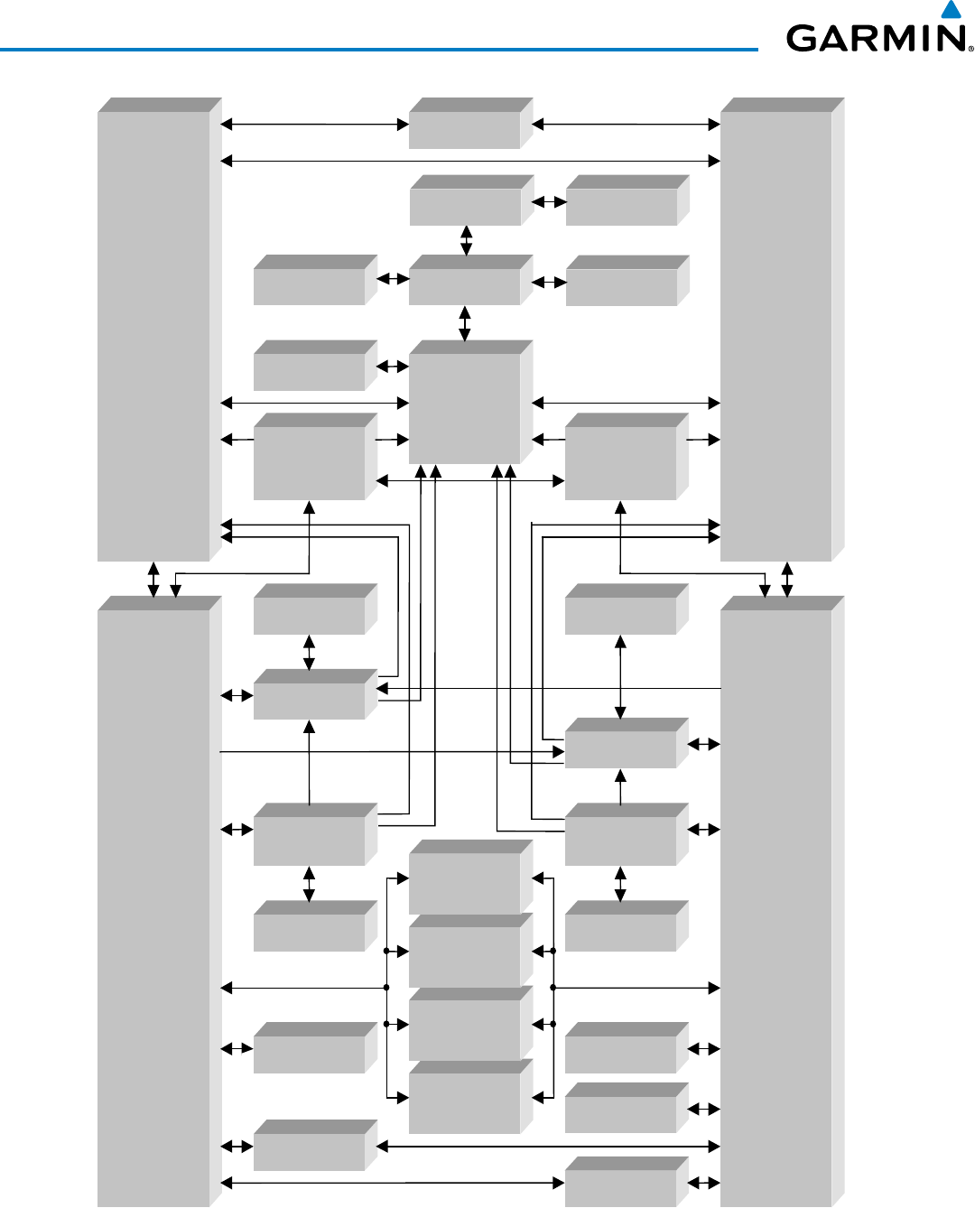
A top-level G1000 system block diagram is shown in Figure 1-1 (it does not include the GSM 85A/86).
NOTE: Refer to the AFCS section for details on the GFC 700 AFCS.
In the Beechcraft 200/B200 Series, the GFC 700 Automated Flight Control System (AFCS) provides the flight
director (FD), autopilot (AP), and yaw damper (YD) functions of the G1000 system.

190-00928-04 Rev. A
Garmin G1000 Pilot’s Guide for the Beechcraft 200/B200 Series
2
SYSTEM OVERVIEW
1.2 LINE REPLACEABLE UNITS (LRU)
•
GDU 1040A
(2) – Each unit is configured as a PFD that features a 10.4-inch LCD with 1024 x 768 resolution.
The unit installed on the left/pilot side is designated as PFD1, and the one installed on the right/copilot side
is designated as PFD2. These units communicate with each other, the MFD, and with the on-side GIA 63W
Integrated Avionics Unit through a High-Speed Data Bus (HSDB) connection.
•
GDU 1500
(1) – Features a 15-inch LCD with 1024 x 768 resolution and is configured as an MFD. This unit
is linked to both PFDs via HSDB connection.
•
GIA 63W
(2) – Functions as the main communication hub, linking all LRUs with the on-side PFD. Each
GIA 63W contains a GPS SBAS receiver, VHF COM/NAV/GS receivers, a flight director (FD) and system
integration microprocessors. Each GIA 63W is paired with the on-side PFD via HSDB connection. The GIA
63Ws are not paired together and do not communicate with each other directly.
•
GDC 74B/7400
(2) – Processes data from the pitot/static system as well as the OAT probe. This unit provides
pressure altitude, airspeed, vertical speed and OAT information to the G1000 system, and it communicates with
the on-side GIA 63W, on-side GDU 1040A, GDU 1040A MFD, and on-side GRS 77/7800, using an ARINC 429
digital interface (it also interfaces directly with the on-side GTP 59). The GDC 74B/7400 is designed to operate
in Reduced Vertical Separation Minimum (RVSM) airspace.
•
GEA 71
(2) – Receives and processes signals from the engine and airframe sensors. This unit communicates
with both GIA 63Ws using an RS-485 digital interface.
•
GRS 77/7800
(2) – Provides aircraft attitude and heading information via ARINC 429 to both the on-side
GDU 1040A, the GDU 1040A MFD, and the on-side GIA 63W. The GRS 77/7800 contains advanced sensors
(including accelerometers and rate sensors) and interfaces with the on-side GMU 44 to obtain magnetic field
information, with the GDC 74B/7400 to obtain air data, and with both GIA 63Ws to obtain GPS information.
AHRS modes of operation are discussed later in this document.
•
GMU 44
(2) – Measures local magnetic field. Data is sent to the GRS 77/7800 for processing to determine
aircraft magnetic heading. This unit receives power directly from the GRS 77 and communicates with the
GRS 77/7800, using an RS-485 digital interface.
•
GMA 1347D
(2) – Integrates NAV/COM digital audio, intercom system and marker beacon controls, and is
installed in dual configuration on the outboard side of PFD1 and PFD2. This unit also enables the manual
control of the display reversionary mode (red
DISPLAY BACKUP
button) and communicates with the on-side
GIA 63W, using an RS-232 digital interface.
•
GTX 33/33D/3000
(2) – Solid-state transponders that provide Modes A, C, S and ADS-B capability. Both
transponders can be controlled from either PFD, and only one transponder can be active at a time. Each
transponder communicates with the on-side GIA 63W through an RS-232 digital interface.
•
GDL 69A
(1) – A satellite radio receiver that provides data link weather information to the G1000 MFD (and,
indirectly, to the inset map of the PFD) as well as digital audio entertainment. The GDL 69A communicates with
the MFD via HSDB connection. Subscriptions to the SiriusXM Weather or SiriusXM Satellite Radio services are
required to enable the GDL 69A capability.
•
GDL 59
(1) – GDL 59 operation is performed with the MFD through the HSDB. Connectivity with the GSR 56
for the Iridium telephone feature is through the RS-232 bus.

190-00928-04 Rev. A
Garmin G1000 Pilot’s Guide for the Beechcraft 200/B200 Series
3
SYSTEM OVERVIEW
•
GSR 56
(1) – The Iridium Transceiver operation for voice communication is by means of a telephone handset in
the cabin and pilot and copilot headsets in the cockpit. The transceiver can also send and receive data provided
by the GDL 59 through the RS-232 bus, and provide Garmin Connext Weather and SMS functions.
•
GWX 68/70
(1) – Provides airborne weather and ground mapped radar data to the MFD, through the GDL 69A,
via HSDB connection.
•
GCU 477
(1) – Provides the Flight Management System (FMS) controls for the MFD through an RS-232 digital
interface.
•
GMC 710
(1) – Provides the controls for the GFC 700 AFCS through an RS-232 digital interface allowing
communication with both PFDs.
•
GTP 59
(2) – Provides Outside Air Temperature (OAT) data to the on-side GDC 74B/7400.
•
GTS 800/820/825/850/855/8000
– The GTS 800/820/825 Traffic Advisory System (TAS), GTS 850/855 TCAS
I, and GTS 8000 TCAS II use active interrogations of Mode S and Mode C transponders to provide traffic
information to the pilot independent of the air traffic control system.
•
GRA 5500
(1) – Provides altitude above the ground (AGL) to the MFD, through the GIA 63W, via HSDB
connection.
•
GA 58
– The GA 58 is directional antenna for the Traffic Avoidance System. One top-mounted directional
antenna is required. Optional bottom mounted antenna offers better threat visibility.
•
GA 36
(1) and
GA 37
(1) – The GA 36 is a through-mount GPS/SBAS antenna. The GA 37 is a through-mount
GPS/SBAS antenna with XM/Data Link.
•
GSA 80
(4), and
GSM 85A/GSM 86
(4) – The GSA 80 servos are used for the automatic control of roll, pitch,
and yaw, and pitch trim. These units interface with each GIA 63W. The servo gearboxes are responsible for
transferring the output torque of the servo actuator to the mechanical flight-control surface linkage.
190-00928-04 Rev. A
Garmin G1000 Pilot’s Guide for the Beechcraft 200/B200 Series
4
SYSTEM OVERVIEW
GDU 1040A
(PFD #1)
GDU 1040A
(PFD #2)
GDU1500
(MFD)
GIA63W #2
GSA80
(Yaw)
GSA80
(Roll)
GSA 80
(Pitch)
GSA 80
(Pitch Trim)
GRS 77/7800
#1
GIA 63W #1
GMC710
GMU44#1
GEA71#2
GEA71#1
GDC 74B/7400
#1
GTP59#1
GMA1347D
#2
GMA1347D
#1
GTX 33/33D/
3000 #1
GDL 69AGWX 68/70
GCU 477
GTX 33/33D/
3000 #2
GRA 5500
GRS 77/7800
#2
GMU44#2
GDC 74B/7400
#2
GTP59#2
VHF COM
VHF NAV/LOC
GPS/SBAS
G/S
AFCS Mode Logic
Flight Director
Servo Management
VHF COM
VHF NAV/LOC
GPS/SBAS
G/S
AFCS Mode Logic
Flight Director
Servo Management
GSR 56GDL 59
GTS 8XX/8000
Figure 1-1 G1000 System (LRU Configuration)
190-00928-04 Rev. A
Garmin G1000 Pilot’s Guide for the Beechcraft 200/B200 Series
5
SYSTEM OVERVIEW
1.3 G1000 CONTROLS
NOTE: The Audio Panel (GMA 1347D) and AFCS controls (GMC 710) are described in the CNS & Audio Panel
and AFCS sections respectively.
The G1000 system controls are located on the PFD and MFD bezels, MFD Control Unit, AFCS Control Unit and
audio panel. The controls for the PFD and MFD are discussed within the following pages of this section.
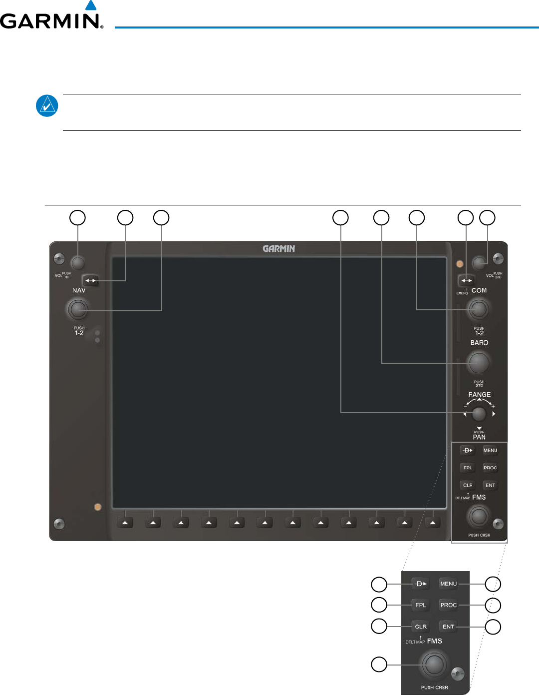
PFD CONTROLS
Figure 1-2 PFD Controls
21 5
468
7
3
11
12
10
9
15
14
13

190-00928-04 Rev. A
Garmin G1000 Pilot’s Guide for the Beechcraft 200/B200 Series
6
SYSTEM OVERVIEW
The following list provides an overview of the controls located on the PFD bezel (see Figure 1-2).
1
NAV VOL/ID Knob
– Controls NAV audio volume level. Press to toggle the Morse code identifier audio ON
and OFF. Volume level is shown in the NAV frequency field as a percentage.
2
NAV Frequency Transfer Key
– Toggles the standby and active NAV frequencies.
3
Dual
NAV Knob
– Tunes the standby frequencies for the NAV receiver (large knob for MHz; small knob for
kHz). Press to switch the tuning box (cyan box) between NAV1 and NAV2.
4
Joystick
– Changes the map range when rotated. Activates the map pointer when pressed.
5
BARO Knob
– Sets the altimeter barometric pressure. Press to enter standard pressure (29.92).
6
Dual COM Knob
– Tunes the standby frequencies for the COM transceiver (large knob for MHz; small
knob for kHz). Press to switch the tuning box (cyan box) between COM1 and COM2.
7
COM Frequency Transfer Key
– Toggles the standby and active COM frequencies. Press and hold this
key for two seconds to tune the emergency frequency (121.5 MHz) automatically into the active frequency
field.
8
COM
VOL/SQ Knob
– Controls COM audio volume level. Volume level is shown in the COM frequency
field as a percentage. Press to turn the COM automatic squelch ON and OFF.
9
Direct-to Key ( )
– Allows the user to enter a destination waypoint and establish a direct course to the
selected destination (the destination is either specified by the identifier, chosen from the active route, or
taken from the map pointer position).
10
FPL Key
– Displays the active Flight Plan Page for creating and editing the active flight plan.
11
CLR
Key
– Erases information, cancels entries, or removes page menus. Pressing and holding this key
displays the Navigation Map Page automatically.
12
Dual FMS Knob
– Flight Management System Knob. Press the
FMS
Knob to turn the selection cursor
ON and OFF. When the cursor is ON, data may be entered in the applicable window by turning the small
and large
knobs. The large
knob moves the cursor on the page, while the small
knob selects individual
characters for the highlighted cursor location.
13
MENU Key
– Displays a context-sensitive list of options. This list allows the user to access additional
features or make setting changes that relate to particular pages.
14
PROC Key
– Gives access to IFR departure procedures (DPs), arrival procedures (STARs) and approach
procedures (IAPs) for a flight plan. If a flight plan is used, available procedures for the departure and/or
arrival airport are automatically suggested. These procedures can then be loaded into the active flight plan.
If a flight plan is not used, both the desired airport and the desired procedure may be selected.
15
ENT Key
– Validates or confirms a menu selection or data entry.
190-00928-04 Rev. A
Garmin G1000 Pilot’s Guide for the Beechcraft 200/B200 Series
7
SYSTEM OVERVIEW
CONTROLS ASSOCIATED WITH THE MFD
The controls for the MFD (GDU 1500) are located on both the MFD bezel and the Control Unit (GCU 477).
The bottom portion of the MFD bezel features 12 softkeys that are designed to perform various functions
depending upon the specific page being displayed. These softkeys are discussed throughout the Pilot’s Guide
documentation.
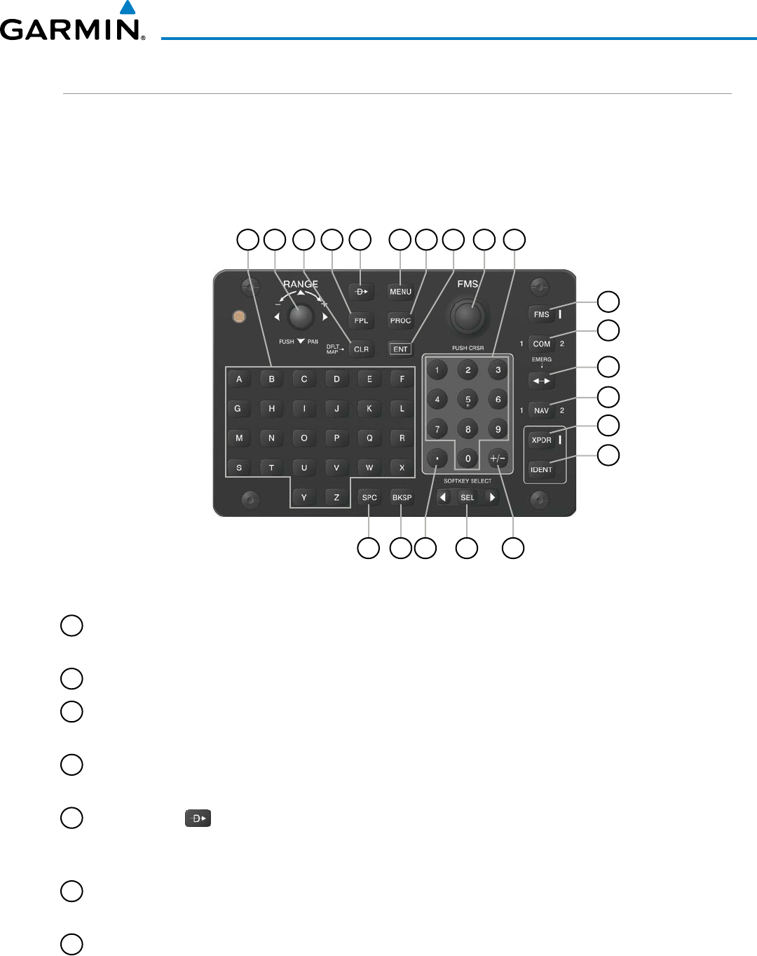
The following list provides an overview of the controls located on the Control Unit (see Figure 1-3):
Figure 1-3 Control Unit (GCU 477)
6 75
17
2 84 93
11
12
13
14
15
16
19 182021
1 10
1
Alphabetic Keys
– Allow the user to enter letters quickly, without having to select individual characters
with the
FMS
Knob.
2
Joystick
– Changes the map range when rotated. Activates the map pointer when pressed.
3
CLR
Key
– Erases information, cancels entries, or removes page menus. Pressing and holding this key
displays the Navigation Map Page automatically.
4
FPL Key
– Displays the active Flight Plan Page for creating and editing the active flight plan, or for
accessing stored flight plans.
5
Direct-to Key ( )
– Allows the user to enter a destination waypoint and establish a direct course to the
selected destination (the destination is either specified by the identifier, chosen from the active route, or
taken from the map pointer position).
6
MENU Key
– Displays a context-sensitive list of options. This list allows the user to access additional
features or make setting changes that relate to particular pages.
7
PROC Key
– Gives access to IFR departure procedures (DPs), arrival procedures (STARs) and approach
procedures (IAPs) for a flight plan. If a flight plan is used, available procedures for the departure and/or
arrival airport are automatically suggested. Theses procedures can then be loaded into the active flight
plan. If a flight plan is not used, both the desired airport and the desired procedure may be selected.

190-00928-04 Rev. A
Garmin G1000 Pilot’s Guide for the Beechcraft 200/B200 Series
8
SYSTEM OVERVIEW
8
ENT Key
– Validates or confirms a menu selection or data entry.
9
Dual FMS Knob
– Flight Management System Knob. When the FMS Key is pressed, this knob selects the
MFD page to be viewed. The large
knob selects a page group (MAP, WPT, AUX, NRST), while the small
knob selects a specific page within the page group. Pressing the
FMS
Knob turns the selection cursor ON
and OFF. When the cursor is ON, data may be entered in the applicable window by turning the small
and large
knobs. In this case, the large
knob moves the cursor on the page, while the small
knob selects
individual characters for the highlighted cursor location. This knob also tuning capability for the COM
and NAV radios when the appropriate COM or NAV key is pressed. When the XPDR Key is pressed, the
transponder code may be entered using the FMS Knob.
10
FMS Key
– Sets the FMS Knob to control FMS functions on the MFD. When pressed, an annunciator next
to the key illuminates indicating adjustment of the FMS Knob will now affect FMS functions.
11
Numeric Keys
– Allow the user to enter numbers quickly, without having to select individual characters
with the
FMS
Knob.
12
COM Key
– Sets the FMS Knob to control tuning of the COM radios. The first press will select COM1,
as indicated by an illuminated “1” to the left of the key. Press again to select COM2. This is annunciated
with a “2” to the right of the key. Each subsequent press of the COM Key will switch between COM1 and
COM2. Use the FMS Knob to tune the selected COM.
13
Frequency Transfer Key
(EMERG) – Switches the standby and active COM or NAV frequencies. Press
and hold this key for two seconds to tune the emergency frequency (121.5 MHz) automatically into the
active frequency field.
14
NAV Key
– Sets the FMS Knob to control tuning of the NAV radios. The first press will select NAV1, as
indicated by an illuminated “1” to the left of the key. Press again to select NAV2. This is annunciated with
a “2” to the right of the key. Each subsequent press of the N AV Key will switch between NAV1 and NAV2.
Use the FMS Knob to tune the selected NAV.
15
XPDR Key
– Sets the FMS Knob to enter transponders codes. When pressed, an annunciator next to the
key illuminates indicating the FMS Knob can now be used for transponder code entry.
16
IDENT Key
– Activates transponder IDENT function.
17
Plus (+) Minus (-) Key
– Toggles a (+) or (-) character.
18
SEL Key
– The center of this key activates the selected MFD softkey, while the right and left arrows move
the softkey selection box to the right and left, respectively.
19
Decimal Key
– Enters a decimal point.
20
BKSP Key
– Moves the cursor back one character space.
21
SPC Key
– Adds a space character.
190-00928-04 Rev. A
Garmin G1000 Pilot’s Guide for the Beechcraft 200/B200 Series
9
SYSTEM OVERVIEW
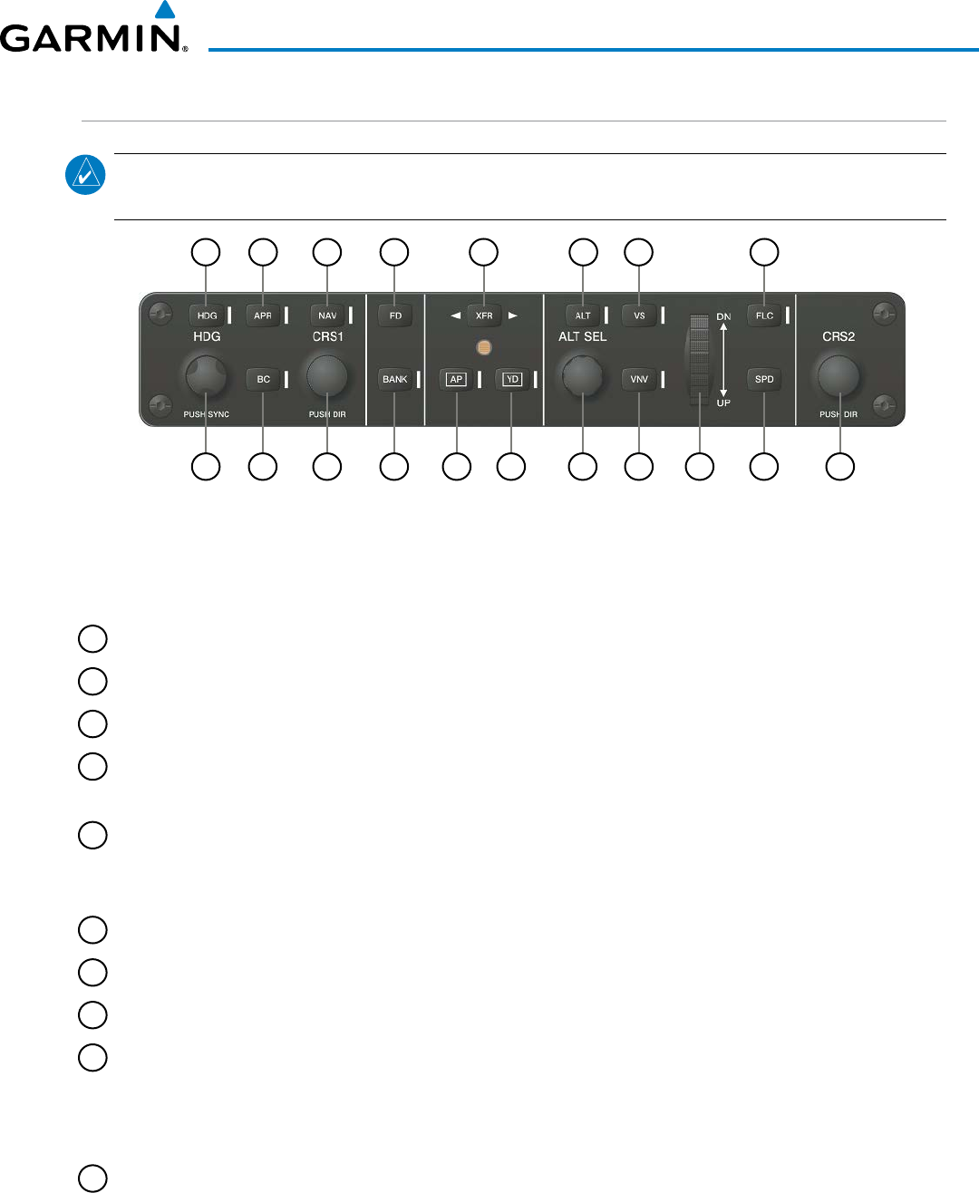
AFCS CONTROLS
NOTE: With the exception of the
FD
and
SPD
Keys, if a key is selected, its respective annunciator is
illuminated.
1 2 3 4 5 6 7 8
10 917 16 15 14 13 12 111819
Figure 1-4 AFCS Control Unit (GMC 710)
The GFC 700 AFCS is mainly controlled through the GMC 710 AFCS Control Unit. The AFCS Control Unit
consists of the following controls:
1
HDG Key
– Selects/deselects Heading Select Mode.
2
APR Key
– Selects/deselects Approach Mode.
3
NAV Key
– Selects/deselects Navigation Mode.
4
FD Key
– Activates/deactivates the flight director in the default pitch and roll modes. If the autopilot is
engaged, the
FD
Key is disabled.
5
XFR Key
– Switches the autopilot between the pilot-side and the copilot-side flight directors. This selection
also selects which air data computer is communicating with the active transponder. Upon power-up, the
pilot-side FD is selected.
6
ALT Key
– Selects/deselects Altitude Hold Mode.
7
VS Key
– Selects/deselects Vertical Speed Mode.
8
FLC Key
– Selects/deselects Flight Level Change Mode.
9
CRS2 Knob
– Sets the copilot-selected course on the HSI of PFD2 when the VOR1, VOR2, or OBS/SUSP
mode is selected. Pressing this knob centers the CDI on the currently selected VOR. The copilot-selected
course provides course reference to the copilot-side flight director when operating in Navigation and
Approach modes.
10
SPD Key
– Switches the Flight Level Change mode reference speed between IAS and MACH number.

190-00928-04 Rev. A
Garmin G1000 Pilot’s Guide for the Beechcraft 200/B200 Series
10
SYSTEM OVERVIEW
11
NOSE UP/DN Wheel
– Controls the active mode reference for the Pitch, Vertical Speed, and Flight Level
Change modes.
12
VNV Key
– Selects/deselects Vertical Navigation mode.
13
ALT SEL Knob
– Sets the selected altitude in the Selected Altitude Box. In addition to providing the
standard G1000 altitude alerter function, selected altitude provides an altitude setting for the Altitude
Capture/Hold mode of the AFCS.
14
YD Key
– Engages/disengages the yaw damper.
15
AP Key
– Engages/disengages the autopilot.
16
BANK Key
– Selects/deselects Low Bank Mode.
17
CRS1 Knob
– Sets the pilot-selected course on the HSI of PFD1 when the VOR1, VOR2, or OBS/SUSP mode
is selected. Pressing this knob centers the CDI on the currently selected VOR. The pilot-selected course
provides course reference to the pilot-side flight director when operating in Navigation and Approach
modes.
18
BC Key
– Selects/deselects Back Course Mode.
19
HDG Knob
– Sets the selected heading on the HSI. When operating in Heading Select mode, this knob
provides the heading reference to the flight director.
ADDITIONAL AFCS CONTROLS
The
AP DISC
(Autopilot Disconnect) Switch,
CWS
(Control Wheel Steering) Button,
GO AROUND
Switch, and
MEPT (Manual Electric Pitch Trim) Switch are additional AFCS
controls and are located in the cockpit,
separately from the AFCS Control Unit. These are discussed in detail in the AFCS section.
190-00928-04 Rev. A
Garmin G1000 Pilot’s Guide for the Beechcraft 200/B200 Series
11
SYSTEM OVERVIEW
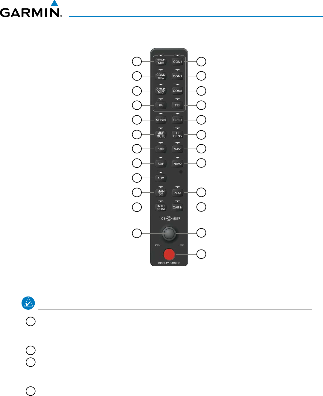
AUDIO PANEL CONTROLS
Figure 1-5 Audio Panel Controls (GMA 1347D)
17
18
15
13
11
9
20
7
5
3
1
22
14
2
16
4
6
8
10
12
24
23
21
19
NOTE: When a key is selected, a triangular annunciator above the key is illuminated.
1
COM1 MIC
– Selects the #1 transmitter for transmitting. COM1 receive is simultaneously selected when
this key is pressed allowing received audio from the #1 COM receiver to be heard. COM2 receiver audio
can be added by pressing the COM2 Key.
2
COM1
– When selected, audio from the #1 COM receiver can be heard.
3
COM2 MIC
– Selects the #2 transmitter for transmitting. COM2 is simultaneously selected when this key
is pressed allowing received audio from the #2 COM receiver to be heard. COM2 can be deselected by
pressing the COM2 Key, or COM1 can be added by pressing the COM1 Key.
4
COM2
– When selected, audio from the #2 COM receiver can be heard.

190-00928-04 Rev. A
Garmin G1000 Pilot’s Guide for the Beechcraft 200/B200 Series
12
SYSTEM OVERVIEW
5
COM3 MIC
– Selects an optional transmitter for transmitting (if installed). COM3 is simultaneously
selected when this key is pressed allowing received audio from the optional receiver to be heard. COM3
can be deselected by pressing the COM3 Key, or either COM1 or COM2 can be added by pressing the
COM1 or COM2 Key.
6
COM3
– When selected, audio from an optional COM can be heard.
7
PA
– Selects the passenger address system. The selected COM transmitter is deselected when the PA Key
is pressed.
8
TEL
– When selected, activates the SATCOM transceiver.
9
MUSIC
– Toggles the Music input on or off. Pressing and holding toggles music muting on or off.
10
SPKR
– Pressing this key selects and deselects the corresponding cockpit speaker. With
SPKR
selected on,
the COM and NAV receiver audio, and alerts are heard on the speaker.
11
MKR/MUTE
– Mutes the currently received marker beacon receiver audio. Unmutes when new marker
beacon audio is received.
12
HI SENS
– Press to increase Marker Beacon Receiver sensitivity. Press again to return to normal.
13
DME
– Pressing turns optional DME audio on or off.
14
NAV1
– When selected, audio from the #1 NAV receiver can be heard.
15
ADF
– Pressing turns on or off the audio from the optional ADF receiver.
16
NAV2
– When selected, audio from the #2 NAV receiver can be heard.
17
AUX
– Not used on the Beechcraft 200/B200 Series.
18
MAN SQ
– Press to enable manual squelch for the intercom. When active, press the ICS Knob to illuminate
‘SQ’. Turn the ICS Knob to adjust squelch.
19
PLAY
– Press once to play the last recorded audio. Press again to stop playing. Press twice quickly while
audio is playing and the previous block of recorded audio is played. Each subsequent two presses skips
back to the previously recorded block.
20
INTR COM
– Pressing selects the pilot/copilot intercom on both audio panels. Press again to deselect the
intercom.
21
CABIN
– Initiates intercom communications with passengers in the cabin.
22
ICS Knob
– Turn to adjust intercom volume or squelch. Press to switch between volume and squelch
control as indicated by the ‘VOL’ or ‘SQ’ being illuminated. The MAN SQ Key must be selected to allow
squelch adjustment.
23
MSTR Knob
– The Master Volume Control adjusts volume for the blended NAV, COM, and intercom
audio.
24
Reversionary Mode Button
– Pressing manually selects Reversionary Mode.
190-00928-04 Rev. A
Garmin G1000 Pilot’s Guide for the Beechcraft 200/B200 Series
13
SYSTEM OVERVIEW
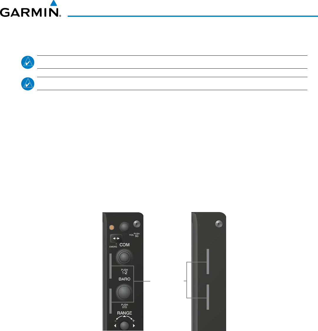
1.4 SECURE DIGITAL CARDS
NOTE:
Refer to the Appendices for instructions on updating the aviation databases.
NOTE:
Ensure that the G1000 system is powered off before inserting the SD card.
The GDU 1040A and GDU 1500 data card slots use Secure Digital (SD) cards and are located on the top
right portion of the display bezels. Each display bezel is equipped with two SD card slots. SD cards are used
for aviation database and system software updates as well as terrain database storage. Also, flight plans may be
imported or exported from an SD card in the MFD.
Install an SD card
Insert the SD card in the SD card slot, pushing the card in until the spring latch engages. The front of the card
should remain flush with the face of the display bezel.
Remove an SD card
Gently press on the SD card to release the spring latch and eject the card.
Figure 1-6 Display Bezel SD Card Slots
PFD MFD
SD Card Slots
190-00928-04 Rev. A
Garmin G1000 Pilot’s Guide for the Beechcraft 200/B200 Series
14
SYSTEM OVERVIEW
1.5 SYSTEM POWER-UP
NOTE: Refer to the Appendices for AHRS initialization bank angle limitations.
NOTE: See the Appendices for additional information regarding system-specific annunciations and alerts.
NOTE: See the Pilot’s Operating Handbook and FAA Approved Airplane Flight Manual (AFM/POH) for specific
procedures concerning avionics power application and emergency power supply operation.
The G1000 system is integrated with the aircraft electrical system and receives power directly from electrical
busses. The G1000 PFDs, MFD and supporting sub-systems include both power-on and continuous built-in test
features that exercise the processor, RAM, ROM, external inputs and outputs to provide safe operation.
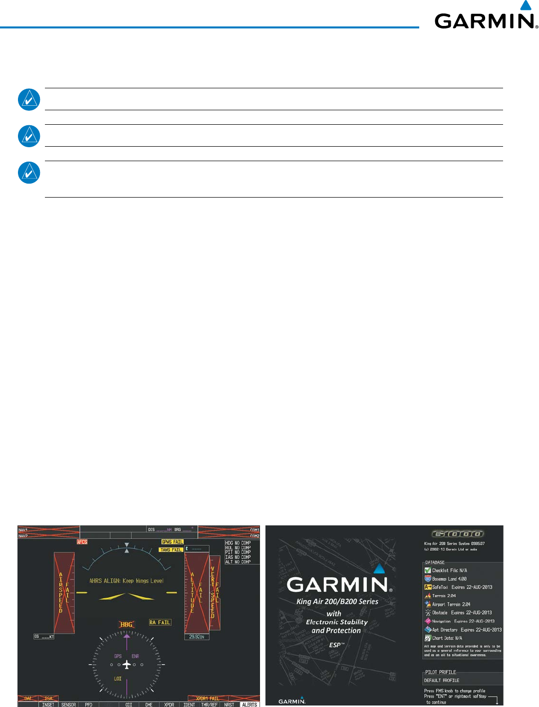
During system initialization, test annunciations are displayed, as shown in Figure 1-7. All system annunciations
should disappear typically within one minute of power-up. Upon power-up, key annunciator lights also become
momentarily illuminated on the audio panels, the control units and the display bezels.
On the PFD, the AHRS begins to initialize and displays ‘AHRS ALIGN: Keep Wings Level’. The AHRS should
display valid attitude and heading fields typically within one minute of power-up. The AHRS can align itself both
while taxiing in a straight line and during level flight.
When the MFD powers up (Figure 1-8), the MFD Power-up Page displays the following information:
• System version • Airport Terrain database name and version
• Copyright • Obstacle database name and effective dates
• Land database name and version • Navigation database name and effective dates
• Safe Taxi database name and effective dates • Airport Directory name and effective dates
• Terrain database name and version • FliteCharts/ChartView database information
Current database information includes the valid operating dates, cycle number and database type. When this
information has been reviewed for currency (to ensure that no databases have expired), the pilot is prompted
to continue. Pressing the
ENT
Key
acknowledges this information and displays the Auxiliary (AUX) Weight
Planning Page.
Figure 1-8 MFD Power-up PageFigure 1-7 PFD Initialization
190-00928-04 Rev. A
Garmin G1000 Pilot’s Guide for the Beechcraft 200/B200 Series
15
SYSTEM OVERVIEW
1.6 SYSTEM OPERATION
The displays are connected together via multiple data busses, thus allowing for high-speed communication.
As shown in Figure 1-1, each GIA 63W is connected to the on-side PFD. This section discusses the normal and
reversionary modes of operation as well as the various AHRS modes of the G1000 system.
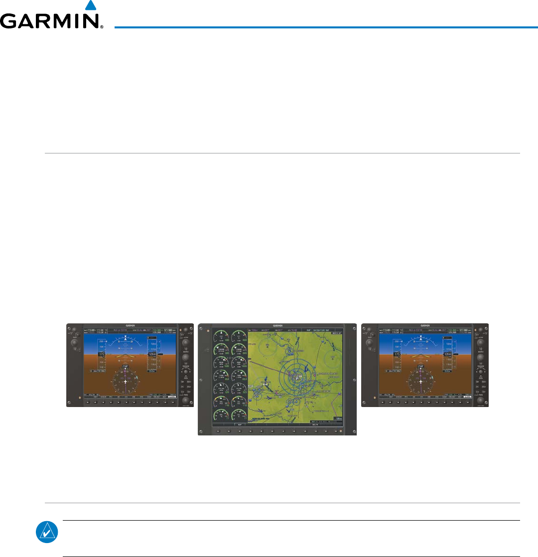
NORMAL OPERATION
PFD
In normal mode, the PFD presents graphical flight instrumentation (attitude, heading, airspeed, altitude
and vertical speed), thereby replacing the traditional flight instrument cluster. The PFD also offers control for
COM and NAV frequency selection.
MFD
In normal mode, the right portion of the MFD displays a full-color moving map with navigation information,
while the left portion of the MFD is dedicated to the Engine Indication System (EIS).
Figure 1-9 gives an example of the G1000 displays in normal mode.
Figure 1-9 Normal Operation
MFD
PFD1 PFD2
REVERSIONARY MODE
NOTE: The G1000 system alerts the pilot when backup paths are utilized by the LRUs. Refer to the Appendices
for further information regarding system-specific alerts.
Reversionary mode is a mode of operation in which all important flight information is presented identically
on at least one of the remaining displays (see Figure 1-10). Transition to reversionary mode should be
straightforward for the pilot, for flight parameters are presented in the same format as in normal mode.
When a display fails, the G1000 system automatically switches to reversionary (backup) mode as follows:
•
PFD1 failure
– MFD and PFD2 remain in normal mode.
•
MFD failure
– PFD1 automatically switches to reversionary mode.
•
PFD2 failure
– MFD and PFD1 remain in normal mode.
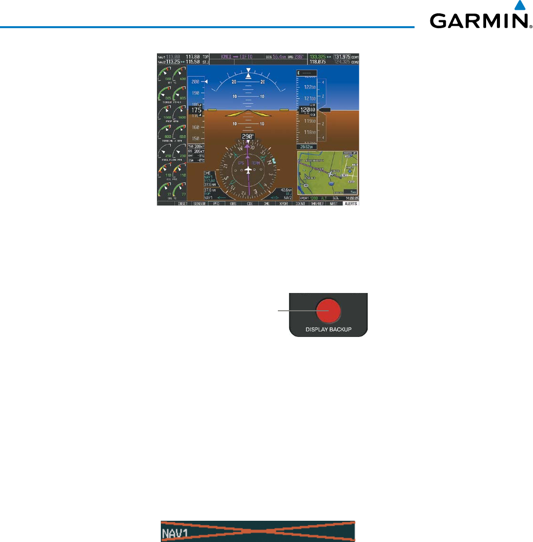
190-00928-04 Rev. A
Garmin G1000 Pilot’s Guide for the Beechcraft 200/B200 Series
16
SYSTEM OVERVIEW
Figure 1-10 Reversionary Mode
Reversionary mode can be activated manually by pressing the dedicated
DISPLAY BACKUP
button at the
bottom of the audio panel (see Figure 1-11 and refer to the Audio Panel section for further details). Pressing
this button again deactivates reversionary mode.
Figure 1-11 DISPLAY BACKUP Button
Pressing the DISPLAY BACKUP
button activates/deactivates
reversionary mode for both the
on-side PFD and the MFD.
Each display can be configured to operate in reversionary mode, as follows:
•
PFD1
– By pressing the
DISPLAY BACKUP
button on the left audio panel.
•
MFD
– By pressing the
DISPLAY BACKUP
button on the left or the right audio panel.
•
PFD2
– By pressing the
DISPLAY BACKUP
button on the right audio panel.
Should the connection between a PFD and the on-side GIA 63W become inoperative, the on-side GIA 63W
can no longer communicate with the remaining PFD (refer to Figure 1-1). As a result, the NAV and COM
functions provided to the failed PFD by the on-side GIA 63W are flagged as invalid (red “X”) on the remaining
PFD (see Figure 1-12).
Figure 1-12 Inoperative Input (NAV1 Shown)
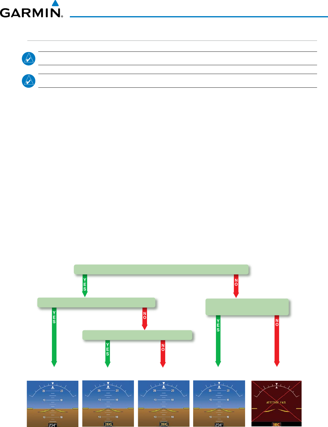
190-00928-04 Rev. A
Garmin G1000 Pilot’s Guide for the Beechcraft 200/B200 Series
17
SYSTEM OVERVIEW
AHRS OPERATION
NOTE: Refer to the Appendices for specific AHRS alert information.
NOTE: Aggressive maneuvering while AHRS is not operating normally may degrade AHRS accuracy.
The Attitude and Heading Reference System (AHRS) performs attitude, heading, and vertical acceleration
calculations for the G1000 System, using GPS, magnetometer, air data, and internal inertial sensors. Attitude
and heading information are updated on the PFD(s) while the AHRS receives appropriate combinations of
information from the external sensor inputs.
The AHRS corrects for shifts and variations in the Earth’s magnetic field by applying the Magnetic Field
Variation Database. The Magnetic Field Variation Database is derived from the International Geomagnetic
Reference Field (IGRF). The IGRF is a mathematical model that describes the Earth’s main magnetic field
and its annual rate of change. The database is updated approximately every five years. See the Appendices
for information on updating the Magnetic Field Variation Database. The system will prompt you on startup
when an update is available. Failure to update this database could lead to erroneous heading information being
displayed to the pilot.
GRS 77 OPERATION
In normal mode, the GRS 77 AHRS relies upon GPS and magnetic field measurements (air data is not used).
If one or more of these three external inputs is unavailable or unreliable, the AHRS uses the remaining inputs
for attitude/heading determination. Four AHRS modes of operation are available (Figure 1-13) and depend
upon the combination of available sensor inputs. Loss of air data, GPS, or magnetometer sensor inputs is
communicated to the pilot by message advisory alerts.
AHRS no-GPS
Mode
AHRS coast-on-gyros
until invalid
AHRS Normal
Mode
AHRS no-Mag
Mode
AHRS no-Mag/
no-Air Mode
Heading Invalid Heading Invalid Attitude/Heading Invalid
Air Data Available and Reliable?
Mag Data Available and Reliable? Mag Data AND Air Data
Available and Reliable?
GPS Data Available and Reliable?
Figure 1-13 AHRS Modes (GRS 77)

190-00928-04 Rev. A
Garmin G1000 Pilot’s Guide for the Beechcraft 200/B200 Series
18
SYSTEM OVERVIEW
aHRS FailuRe
Failure of the internal AHRS inertial sensors may result in loss of attitude and heading information
(indicated by red ‘X’ flags over the corresponding flight instruments).
gPS inPut FailuRe
The system provides two sources of GPS information. If a single GPS receiver fails, or if the information
provided from one of the GPS receivers is unreliable, the AHRS seamlessly transitions to using the other
GPS receiver. An alert message informs the pilot of the use of the backup GPS path. If both GPS inputs
fail, the AHRS continues to operate in reversionary No-GPS mode so long as the air data and magnetometer
inputs are available and reliable. Unavailable or unreliable air data or magnetometer data in addition to
GPS failure results in loss of all attitude and heading information.
NOTE: In-flight initialization of AHRS, when operating without any valid source of GPS data and at true
air speed values greater than approximately 200 knots, is not guaranteed. Under these rare conditions, it
is possible for in-flight AHRS initialization to take an indefinite amount of time which would result in an
extended period of time where valid AHRS outputs are unavailable.
MagnetoMeteR FailuRe
If the magnetometer input fails, the AHRS transitions to one of the reversionary No-Magnetometer modes
and continues to output valid attitude information. However, if the aircraft is airborne, the heading output
on the PFD does become invalid (as indicated by a red “X”).
aiR Data inPut FailuRe
Failure of the air data input has no effect on the AHRS output while AHRS is receiving valid GPS
information. A failure of the air data input while the AHRS is operating in reversionary No-GPS mode
results in invalid attitude and heading information on the PFD (as indicated by red “X” flags).
GRS 7800 OPERATION
In primary mode, the GRS 7800 AHRS relies upon GPS and magnetic field measurements (air data is not
used). If either GPS or magnetometer data is unavailable or unreliable, the AHRS uses the remaining inputs
for attitude/heading determination. In DG Free Mode, the magnetometer data is replaced by a heading value
set by the flight crew. Four AHRS modes of operation are available (Figure 1-14) and depend upon the
combination of available sensor inputs. Loss of GPS or magnetometer sensor inputs is communicated to the
pilot by message advisory alerts. Refer to the Flight Instruments section for further discussion of DG Free
Mode.
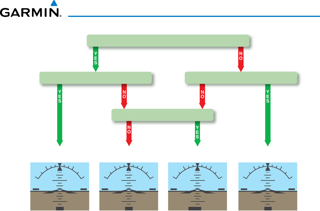
190-00928-04 Rev. A
Garmin G1000 Pilot’s Guide for the Beechcraft 200/B200 Series
19
SYSTEM OVERVIEW
10 10
10 10
360‘
10 10
10 10
10 10
10 10
360‘
AHRS
Classical Mode
AHRS
Primary Mode
AHRS
No-Magnetometer Mode
Heading Invalid,
DG Free Mode Available
AHRS
DG Free Mode
Heading Entered by Pilot
GPS Data Available and Reliable?
Mag Data Available & Reliable?Mag Data Available & Reliable?
Manual DG Selection?
10 10
10 10
360‘ 360‘
FREE
Figure 1-14 AHRS Modes (GRS 7800)
gPS inPut FailuRe
Two GPS inputs are provided to the AHRS. If GPS information from one of the inputs fails, the AHRS
uses the remaining GPS input and an alert message is issued to inform the pilot. If both GPS inputs fail,
the AHRS can continue to provide attitude and heading information to the PFD(s) as long as magnetometer
data is available and reliable (air data will be used to aid calculations during speed changes and extended
turns).
MagnetoMeteR FailuRe
If the magnetometer input fails, the AHRS continues to output valid attitude information; however, the
heading output on the PFD(s) is shown in yellow. The pilot can select DG Free mode to provide heading
inputs.
aiR Data inPut FailuRe
Failure of the air data input has no effect on the AHRS output.
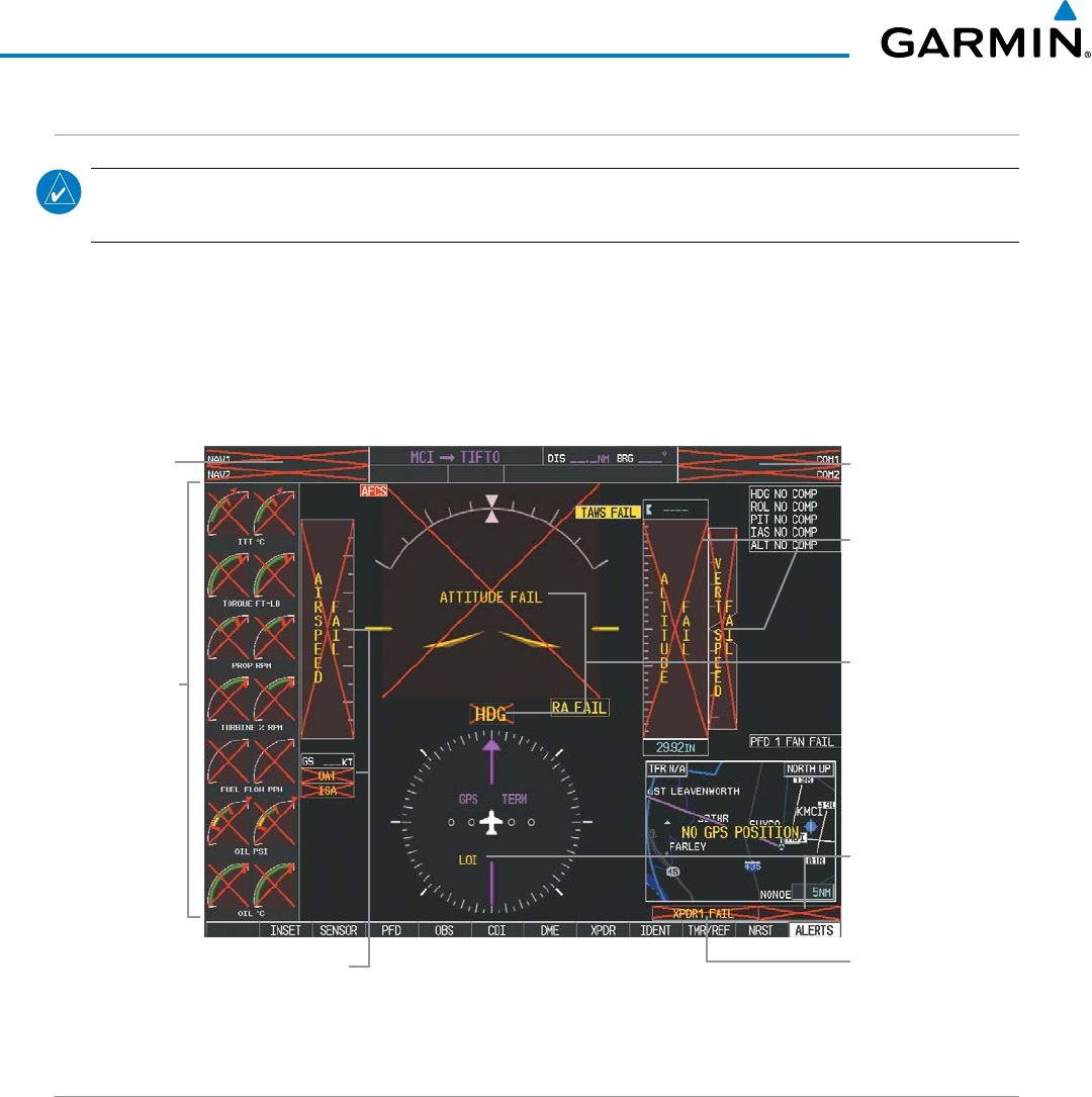
190-00928-04 Rev. A
Garmin G1000 Pilot’s Guide for the Beechcraft 200/B200 Series
20
SYSTEM OVERVIEW
G1000 SYSTEM ANNUNCIATIONS
NOTE: For a detailed description of all annunciations and alerts, refer to Appendix A. Refer to the (AFM/
POH) for additional information regarding pilot responses to these annunciations.
When an LRU or an LRU function fails, a large red “X” is typically displayed on windows associated with
the failed data (Figure 1-14 displays all possible flags and responsible LRUs). Upon G1000 power-up, certain
windows remain invalid as equipment begins to initialize. All windows should be operational within one
minute of power-up. If any window remains flagged, the G1000 system should be serviced by a Garmin-
authorized repair facility.
Figure 1-14 G1000 System Failure Annunciations
GDC 74B Air
Data Computer
GTX 33 Transponder
Or
GIA 63W Integrated
Avionics Units
GDC 74B Air
Data Computer
GEA 71 Engine
Airframe Unit
Or
GIA 63W
Integrated Avionics
Unit
GIA 63W
Integrated Avionics
Units
GRS 77 AHRS
Or
GMU 44
Magnetometer
GIA 63W
Integrated Avionics
Units
GIA 63W
Integrated
Avionics Units
SOFTKEY FUNCTION
The softkeys are located along the bottoms of the displays. The softkeys shown depend on the softkey level
or page being displayed. The bezel keys below the softkeys can be used to select the appropriate softkey. When
a softkey is selected, its color changes to black text on gray background and remains this way until it is turned
off, at which time it reverts to white text on black background.

190-00928-04 Rev. A
Garmin G1000 Pilot’s Guide for the Beechcraft 200/B200 Series
21
SYSTEM OVERVIEW
Softkey Names (displayed)
Figure 1-15 Softkeys (Second-Level PFD Configuration)
Bezel-Mounted Softkeys (press)
Softkey On
Another means of selecting softkeys on the MFD is by using the GCU 477 Control Unit:
Selecting a softkey using the Control Unit
1) Move the softkey selection box to the desired softkey using the arrows of the SEL Key.
2) Press the center of the SEL Key to select the desired softkey.
PFD SOFTKEYS
The
CDI
,
IDENT
,
TMR/REF
,
NRST,
and
ALERTS
Softkeys undergo a momentary change to black text
on gray background and automatically switch back to white text on black background when selected. If
messages remain after acknowledgement, the ALERTS Softkey is black on white.
The PFD softkeys provide control over flight management functions, including GPS, NAV, terrain, traffic,
and lightning (optional). Each softkey sublevel has a BACK Softkey which can be pressed to return to
the previous level. The ALERTS Softkey is visible in all softkey levels. For the top level softkeys and the
transponder (XPDR) levels, the IDENT Softkey remains visible.
LVL1 LVL2 LVL3 LVL4
INSET Displays Inset Map in PFD lower left corner
OFF Removes Inset Map
DCLTR (3) Selects desired amount of map detail; cycles through declutter levels:
DCLTR (No Declutter): All map features visible
DCLTR-1: Declutters land data
DCLTR-2: Declutters land and SUA data
DCLTR-3: Removes everything except for the active flight plan
WX LGND Displays icon and age on the Inset Map for the selected weather products
TRAFFIC Displays traffic information on Inset Map
TRAFFIC: No Traffic displayed on Inset Map
TRFC-1: Traffic displayed on Inset Map
TRFC-2: Traffic Only display shown
TOPO Displays topographical data (e.g., coastlines, terrain, rivers, lakes) and elevation scale
on Inset Map
TERRAIN Displays terrain information on Inset Map (not available with TAWS-A)
STRMSCP Displays Stormscope information on Inset Map (optional)
LVL1 LVL2 LVL3 LVL4

190-00928-04 Rev. A
Garmin G1000 Pilot’s Guide for the Beechcraft 200/B200 Series
22
SYSTEM OVERVIEW
LVL1 LVL2 LVL3 LVL4
NEXRAD
or
PRECIP
Displays XM NEXRAD weather and coverage on Inset Map (optional)
or
Displays Garmin Connext radar precipitation on Inset Map (optional)
XM LTNG
or
DL LTNG
Displays XM lightning information on Inset Map (optional)
or
Displays Garmin Connext data link lightning information on Inset Map (optional)
METAR Displays METAR information on Inset Map (optional)
SENSOR Displays softkeys for selecting the #1 and #2 AHRS and Air Data Computers
ADC1 Selects the #1 Air Data Computer
ADC2 Selects the #2 Air Data Computer
AHRS1 Selects the #1 AHRS
AHRS2 Selects the #2 AHRS
PFD Displays second-level softkeys for additional PFD configurations
SYN VIS Displays the softkeys for enabling or disabling Synthetic Vision features
PATHWAY Displays rectangular boxes representing the horizontal and vertical flight path of the
active flight plan
SYN TERR Enables synthetic terrain depiction
HRZN HDG Displays compass heading along the Zero-Pitch line
APTSIGNS Displays position markers for airports within approximately 15 nm of the current
aircraft position. Airport identifiers are displayed when the airport is within
approximately 9 nm.
DFLTS Resets PFD to default settings, including changing units to standard
WIND Displays softkeys to select wind data parameters
OPTN 1 Wind direction arrow with numeric speed
OPTN 2 Wind direction arrow with numeric direction and magnitude
OPTN 3 Headwind/tailwind and crosswind arrows with numeric speed components
OFF Information not displayed
DME Displays DME Information Window
BRG1 Cycles the Bearing 1 Information Window through NAV1 or GPS waypoint identifier
and GPS-derived distance information, and ADF/frequency.
HSI FRMT Displays the softkeys for selecting the two HSI formats
360 HSI Displays HSI as a 360° compass rose
ARC HSI Displays HSI as a 140° viewable arc
BRG2 Cycles the Bearing 2 Information Window through NAV2 or GPS waypoint identifier
and GPS-derived distance information, and ADF/frequency.
HDG MODE Displays the softkeys for selecting one of the two DG modes (GRS 7800 only)
LVL1 LVL2 LVL3 LVL4

190-00928-04 Rev. A
Garmin G1000 Pilot’s Guide for the Beechcraft 200/B200 Series
23
SYSTEM OVERVIEW
LVL1 LVL2 LVL3 LVL4
DG FREE Allows the DG to enter FREE mode (GRS 7800 only)
DG SLAVE Slaves the DG to the AHRS (GRS 7800 only)
HDG - Slews heading counterclockwise (GRS 7800 only)
HDG + Slews heading clockwise (GRS 7800 only)
HDG SYNC Synchronizes heading to the selected heading (GRS 7800 only)
TRK SYNC Synchronizes heading to the current track (GRS 7800 only)
ALT UNIT Displays softkeys for setting the altimeter and BARO settings to metric units
METERS When enabled, displays altimeter in meters
IN Press to display the BARO setting as inches of mercury
HPA Press to display the BARO setting as hectopacals
STD BARO Sets barometric pressure to 29.92 in Hg (1013 hPa if metric units are selected)
OBS Selects OBS mode on the CDI when navigating by GPS (only available with active leg)
CDI Cycles through GPS, VOR1, and VOR2 navigation modes on the CDI
DME Displays the DME Tuning Window, allowing tuning and selection of the DME
(optional)
Transponder Softkeys without TCAS II
XPDR Displays transponder mode selection softkeys
XPDR1 Selects the #1 transponder as active
XPDR2 Selects the #2 transponder as active
STBY Selects standby mode (transponder does not reply to any interrogations)
ON Selects Mode A (transponder replies to interrogations)
ALT Selects Mode C – altitude reporting mode (transponder replies to identification and
altitude interrogations)
VFR Automatically enters the VFR code (1200 in the U.S.A. only)
CODE Displays transponder code selection softkeys 0-7
0 – 7 Use numbers to enter code
BKSP Removes numbers entered, one at a time
Transponder/Traffic Softkeys with TCAS II
XPDR/TFC Displays the transponder and TCAS II system selection softkeys
XPDR1 Selects the #1 transponder as active
XPDR2 Selects the #2 transponder as active
MODE Displays transponder mode selection softkeys
STBY Selects transponder Standby Mode (transponder does not reply to any interrogations).
When the transponder is set to standby, the TCAS II system is also set to standby.
LVL1 LVL2 LVL3 LVL4
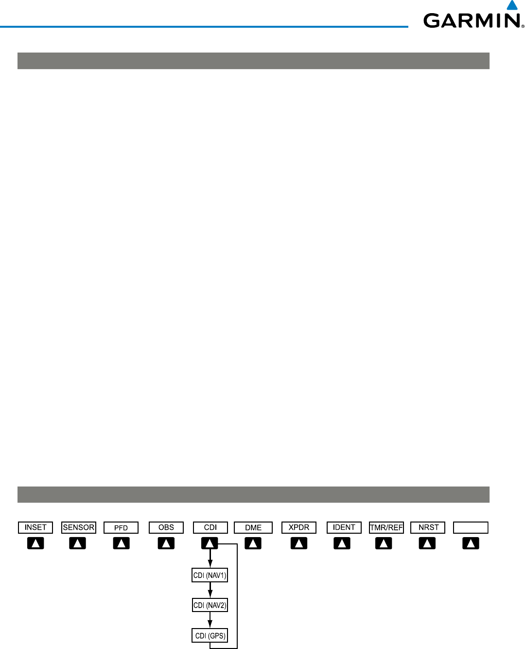
190-00928-04 Rev. A
Garmin G1000 Pilot’s Guide for the Beechcraft 200/B200 Series
24
SYSTEM OVERVIEW
LVL1 LVL2 LVL3 LVL4
ON Activates transponder (transponder replies to identification interrogations). When the
transponder is set to ON, the TCAS II system is set to standby.
ALT Altitude Reporting Mode (transponder replies to identification and altitude
interrogations). When the transponder is set to ALT, the TCAS II system is set to
standby.
TA ONLY Activates the TCAS II system in TA Only Mode and sets the transponder to ALT
TA/RA Activates the TCAS II system in TA/RA Mode and sets the transponder to ALT
TCAS Displays the TCAS control softkeys
REL Displays intruder altitude as altitude relative to own aircraft altitude
ABS Displays intruder MSL altitude
ALT RNG Displays the altitude display range softkeys
ABOVE Displays non-threat traffic from 9900 feet above the aircraft to 2700 feet below the
aircraft. Typically used during climb phase of flight.
NORMAL Displays non-threat traffic from 2700 feet above the aircraft to 2700 feet below the
aircraft. Typically used during enroute phase of flight.
BELOW Displays non-threat traffic from 2700 feet above the aircraft to 9900 feet below the
aircraft. Typically used during descent phase of flight.
UNREST All traffic is displayed
TEST Activates Test Mode and displays test intruder symbols
CODE Displays transponder code selection softkeys 0-7
0 – 7 Use numbers to enter code
BKSP Removes numbers entered, one at a time
IDENT Activates the Special Position Identification (SPI) pulse for 18 seconds, identifying the
transponder return on the ATC screen
TMR/REF Displays Timer/References Window
NRST Displays Nearest Airports Window
ALERTS Displays Alerts Window
LVL1 LVL2 LVL3 LVL4
Figure 1-16 Top Level PFD Softkeys (without TCAS II)
ALERTS
(optional)
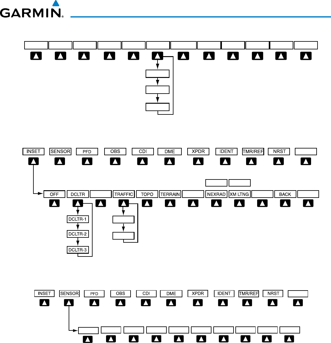
190-00928-04 Rev. A
Garmin G1000 Pilot’s Guide for the Beechcraft 200/B200 Series
25
SYSTEM OVERVIEW
Figure 1-17 Top Level PFD Softkeys (with TCAS II)
DME ALERTS
TRFC/MAP SENSOR PFD OBS CDI XPDR/TFC IDENT TMR/REF NRST
CDI (NAV1)
CDI (NAV2)
CDI (GPS)
(optional)
Figure 1-17 INSET Softkeys
Select the BACK Softkey
to return to the top-level softkeys.
STRMSCP
ALERTS
ALERTS
(
optional
)
(optional)
(optional)
or (optional)
TRFC-1
TRFC-2
(optional)
METAR
PRECIP
(optional)
or
DL LTNG
WX LGND
Figure 1-18 SENSOR Softkeys
Select the BACK Softkey toreturn to the top level softkeys.
BACK
ADC2
ADC1
AHRS1 AHRS2
ALERTS
ALERTS
(
optional
)
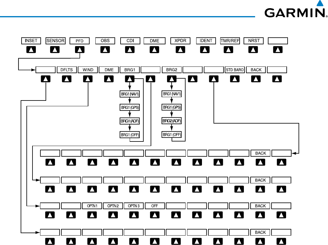
190-00928-04 Rev. A
Garmin G1000 Pilot’s Guide for the Beechcraft 200/B200 Series
26
SYSTEM OVERVIEW
Figure 1-19 PFD Configuration Softkeys
Select the BACK Softkey to return
to the top-level softkeys
ALT UNIT
METERS IN HPA
ALERTS
ALERTS
ALERTS
ALERTS
ALERTS
HSI FRMT
360 HSI ARC HSI ALERTS
(
optional
)
SYN VIS
SYN TERR HRZN HDG
PATHWAY APTSIGNS
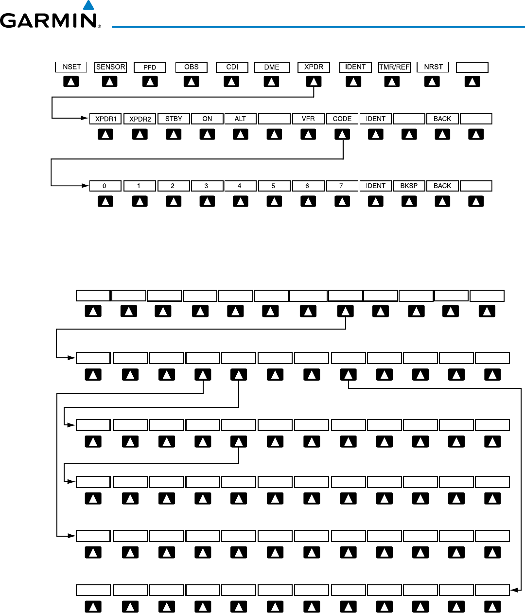
190-00928-04 Rev. A
Garmin G1000 Pilot’s Guide for the Beechcraft 200/B200 Series
27
SYSTEM OVERVIEW
Figure 1-20 XPDR Softkeys (without TCAS II)
Select the BACK Softkey to return
to the top-level softkeys.
Select the BACK Softkey to return to the previous level softkeys.
ALERTS
ALERTS
ALERTS
(optional)
Figure 1-22 XPDR Softkeys (with TCAS II)
ALERTS
ALERTS
DME
TRFC/MAP XPDR/TFC
Press the BACK Softkey to return
to the top-level softkeys.
ALERTSMODE TCAS CODE IDENT
Selecting BACK returns to the
previous softkey level.
Selecting BACK returns to the
previous softkey level.
Selecting BACK returns to the
previous softkey level.
ALERTSREL ABS ALT RNG TEST
TA ONLY TA/RA
SENSOR PFDOBS CDI IDENT TMR/REF NRST ALERTS
BACK
(optional)
STBY ON ALT BACK
BACK
IDENT BKSP BACK0 5432167
ALERTS
Selecting BACK returns to the
previous softkey level.
UNRESTABOVE BELOWNORMAL BACK
XPDR1 XPDR2

190-00928-04 Rev. A
Garmin G1000 Pilot’s Guide for the Beechcraft 200/B200 Series
28
SYSTEM OVERVIEW
MFD SOFTKEYS
LVL1 LVL2 LVL3 LVL4
MAP Enables second-level Navigation Map softkeys
TRAFFIC Displays traffic information on Navigation Map Page
PROFILE Displays profile view on Navigation Map Page
TOPO Displays topographical data (e.g., coastlines, terrain, rivers, lakes) and elevation scale on
Navigation Map Page
TERRAIN Displays terrain information on Navigation Map Page (not available with TAWS-A)
AIRWAYS
(Default label is
dependent on map
setup option
selected)
Displays airways on the map; cycles through the following:
AIRWAYS: No airways are displayed
AIRWY ON: All airways are displayed
AIRWY LO: Only low altitude airways are displayed
AIRWY HI: Only high altitude airways are displayed
STRMSCP Displays Stormscope information on Navigation Map Page (optional)
NEXRAD
or
PRECIP
Displays XM NEXRAD weather and coverage on Navigation Map Page (optional)
or
Displays Worldwide Weather precipitation on Navigation Map Page (optional)
XM LTNG
or
DL LTNG
Displays XM lightning information on Navigation Map Page (optional)
or
Displays Worldwide Weather lightning information on Navigation Map Page (optional)
METAR Displays METAR information on Navigation Map Page (optional)
LEGEND Displays legends for the displayed XM Weather products (optional)
BACK Returns to top-level softkeys
DCLTR (3) Selects desired amount of map detail; cycles through declutter levels:
DCLTR (No Declutter): All map features visible
DCLTR-1: Declutters land data
DCLTR-2: Declutters land and SUA data
DCLTR-3: Removes everything except for the active flight plan
SHW CHRT When available, displays optional airport and terminal procedure charts
CHKLIST When available, displays optional checklists
LVL1 LVL2 LVL3 LVL4
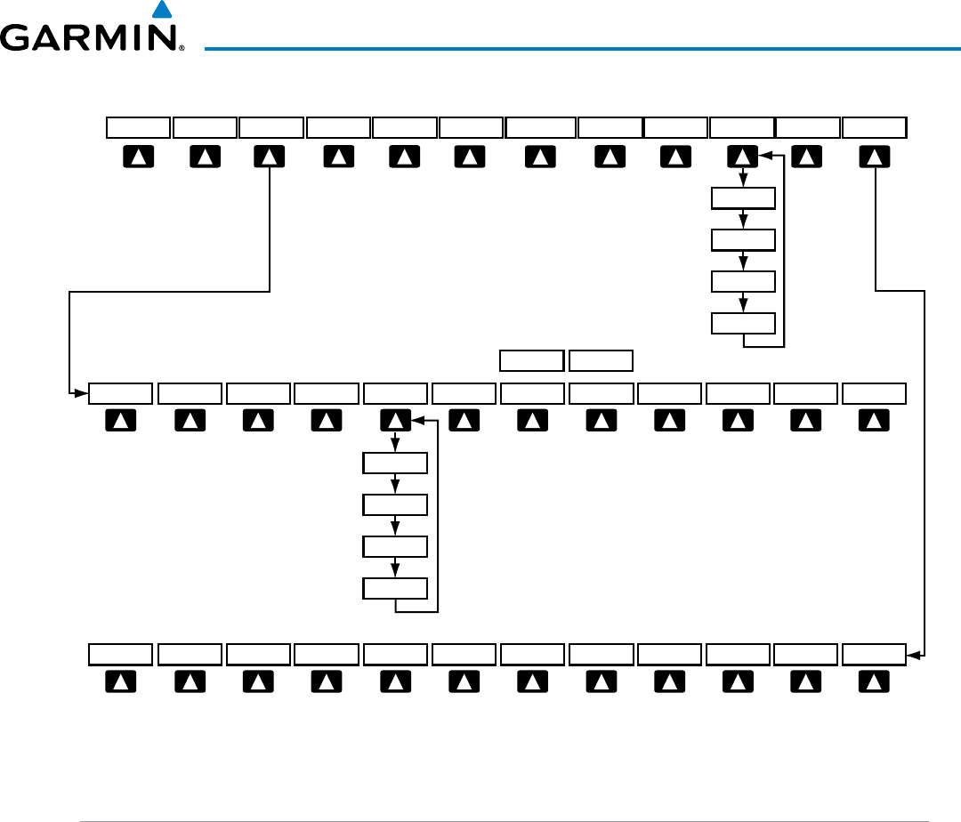
190-00928-04 Rev. A
Garmin G1000 Pilot’s Guide for the Beechcraft 200/B200 Series
29
SYSTEM OVERVIEW
Figure 1-21 MFD Softkeys
DCLTR-1
DCLTR-2
DCLTR
DCLTR-3
AIRWY ON
AIRWY LO
AIRWAYS
AIRWY HI
The DONE Softkey label changes to UNDO
when the checklist item is already checked.
Press the BACK softkey to
return to the top-level softkeys.
CHKLIST
MAP DCLTR SHW CHRT
BACKMETARXM LTNGNEXRADSTRMSCPAIRWAYSTERRAINPROFILE TOPOTRAFFIC
EXIT EMERGCYDONE
(optional) (optional)
(optional)
LEGEND
(optional)
or
PRECIP
or
DL LTNG
(optional) (optional)
GPS RECEIVER OPERATION
Each GIA 63W Integrated Avionics Unit (IAU) contains a GPS receiver. Information collected by the specified
receiver (GPS1 for the #1 IAU or GPS2 for the #2 IAU) may be viewed on the AUX - GPS Status Page.
GPS1 provides information to the pilot-side PFD and GPS2 provides data to the copilot-side PFD. Internal
system checking is performed to ensure both GPS receivers are providing accurate data to the PFDs. In some
circumstances, both GPS receivers may be providing accurate data, but one receiver may be providing a better
GPS solution than the other receiver. In this case the GPS receiver producing the better solution is automatically
coupled to both PFDs. “BOTH ON GPS 1” or “BOTH ON GPS 2” is displayed in the Reversionary Sensor
Window (see Appendix A) indicating which GPS receiver is being used. Both GPS receivers are still functioning
properly, but one receiver is performing better than the other at that particular time.
These GPS sensor annunciations are most often seen after system power-up when one GPS receiver has
acquired satellites before the other, or one of the GPS receivers has not yet acquired a SBAS signal. While
the aircraft is on the ground, the SBAS signal may be blocked by obstructions causing one GPS receiver to
have difficulty acquiring a good signal. Also, while airborne, turning the aircraft may result in one of the GPS
receivers temporarily losing the SBAS signal.
If the sensor annunciation persists, check for a system failure message in the Messages Window on the PFD.
If no failure message exists, check the GPS Status Page and compare the information for GPS1 and GPS2.
Discrepancies may indicate a problem.
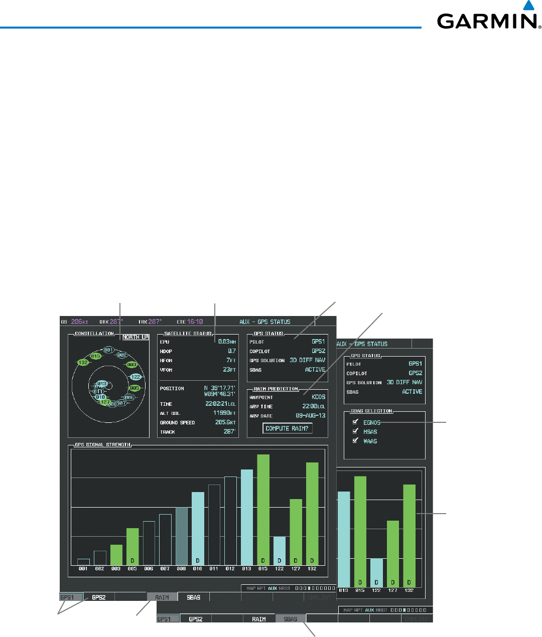
190-00928-04 Rev. A
Garmin G1000 Pilot’s Guide for the Beechcraft 200/B200 Series
30
SYSTEM OVERVIEW
Viewing GPS receiver status information
1) Use the large FMS Knob to select the Auxiliary Page Group (see Section 1.7 for information on navigating MFD
page groups).
2) Use the small FMS Knob to select GPS Status Page.
Selecting the GPS receiver for which data may be reviewed
1) Use the FMS Knob to select the AUX - GPS Status Page.
2) To change the selected GPS receiver:
a) Select the desired
GPS
Softkey.
Or:
a) Press the MENU Key.
b) Use the FMS Knob to highlight the receiver which is not selected and press the ENT Key.
Figure 1-22 GPS Status Page (RAIM or SBAS Selected)
Satellite Signal
Strength Bars
Satellite Constellation
Diagram Satellite Signal
Information Status RAIM
Availability
Prediction
GPS Receiver
Status
EGNOS, MSAS
and WAAS
Selected
RAIM Softkey
Selected
SBAS Softkey
Selected
GPS Selection
Softkeys
The GPS Status Page provides the following information:

190-00928-04 Rev. A
Garmin G1000 Pilot’s Guide for the Beechcraft 200/B200 Series
31
SYSTEM OVERVIEW
• Satellite constellation diagram
Satellites currently in view are shown at their respective positions on a sky view diagram. The sky view is
always in a north-up orientation, with the outer circle representing the horizon, the inner circle representing
45° above the horizon, and the center point showing the position directly overhead.
Each satellite is represented by an oval containing the Pseudo-random noise (PRN) number (i.e., satellite
identification number). Satellites whose signals are currently being used are represented by solid ovals.
• Satellite signal information status
The accuracy of the aircraft’s GPS fix is calculated using Estimated Position Uncertainty (EPU), Dilution
of Precision (DOP), and horizontal and vertical figures of merit (HFOM and VFOM). EPU is the radius of a
circle centered on an estimated horizontal position in which actual position has 95% probability of laying.
EPU is a statistical error indication and not an actual error measurement.
DOP measures satellite geometry quality (i.e., number of satellites received and where they are relative to
each other) on a range from 0.0 to 9.9, with lower numbers denoting better accuracy. HFOM and VFOM,
measures of horizontal and vertical position uncertainty, are the current 95% confidence horizontal and
vertical accuracy values reported by the GPS receiver.
The current calculated GPS position, time, altitude, ground speed, and track for the aircraft are displayed
below the satellite signal accuracy measurements.
• GPS receiver status
The GPS solution type (ACQUIRING, 2D NAV, 2D DIFF NAV, 3D NAV, 3D DIFF NAV) for the active
GPS receiver (GPS1 or GPS2) is shown in the upper right of the GPS Status Page. When the receiver is
in the process of acquiring enough satellite signals for navigation, the receiver uses satellite orbital data
(collected continuously from the satellites) and last known position to determine the satellites that should be
in view. ACQUIRING is indicated as the solution until a sufficient number of satellites have been acquired
for computing a solution.
When the receiver is in the process of acquiring a 3D differential GPS solution, 3D NAV is indicated as the
solution until the 3D differential fix has finished acquisition. SBAS (Satellite-Based Augmentation System)
indicates INACTIVE. When acquisition is complete, the solution status indicates 3D DIFF NAV and SBAS
indicates ACTIVE.
• RAIM (Receiver Autonomous Integrity Monitoring) Prediction (RAIM Softkey is selected)
In most cases performing a RAIM prediction is not necessary. However, in some cases, the selected approach
may be outside the SBAS coverage area and it may be necessary to perform a RAIM prediction for the intended
approach.
Receiver Autonomous Integrity Monitoring (RAIM) is a GPS receiver function that performs a consistency
check on all tracked satellites. RAIM ensures that the available satellite geometry allows the receiver to
calculate a position within a specified RAIM protection limit (2.0 nautical miles for oceanic and enroute, 1.0
nm for terminal, and 0.3 nm for non-precision approaches). During oceanic, enroute, and terminal phases of
flight, RAIM is available nearly 100% of the time.
The RAIM prediction function also indicates whether RAIM is available at a specified date and time. RAIM
computations predict satellite coverage within ±15 min of the specified arrival date and time.

190-00928-04 Rev. A
Garmin G1000 Pilot’s Guide for the Beechcraft 200/B200 Series
32
SYSTEM OVERVIEW
Because of the tighter protection limit on approaches, there may be times when RAIM is not available. The
G1000 automatically monitors RAIM and warns with an alert message when it is not available. If RAIM is not
predicted to be available for the final approach course, the approach does not become active, as indicated by
the messages “Approach is not active” and “RAIM not available from FAF to MAP”. If RAIM is not available
when crossing the FAF, the missed approach procedure must be flown.
Predicting RAIM availability at a selected waypoint
1) Select the GPS Status Page.
2) If necessary, select the RAIM Softkey.
3) Press the
FMS
Knob
. The ‘WAYPOINT’ field is highlighted.
4) Turn the small FMS Knob to display the Waypoint Information Window.
5) Enter the desired waypoint:
a) Use the FMS Knob to enter the desired waypoint by identifier, facility, or city name and press the ENT Key. Refer
to Section 1.7 for instructions on entering alphanumeric data into the G1000.
Or:
a) Turn the small FMS Knob counter-clockwise to display a list of flight plan waypoints (the FPL list is populated
only when navigating a flight plan).
b) Turn the small FMS Knob clockwise to display the NRST, RECENT, or AIRWAY waypoints, if required.
c) Turn the large FMS Knob clockwise to select the desired waypoint. The G1000 automatically fills in the identifier,
facility, and city fields with the information for the selected waypoint.
d) Press the ENT Key to accept the waypoint entry.
6) Use the FMS Knob to enter an arrival time and press the ENT Key.
7) Use the FMS Knob to enter an arrival date and press the ENT Key.
8) With the cursor highlighting ‘COMPUTE RAIM?’, press the ENT Key. Once RAIM availability is computed, one
of the following is displayed:
• ‘COMPUTE RAIM?’—RAIM has not been computed for the current waypoint, time, and date combination
• ‘COMPUTING AVAILABILITY’—RAIM calculation in progress
• ‘RAIM AVAILABLE’—RAIM is predicted to be available for the specified waypoint, time, and date
• ‘RAIM NOT AVAILABLE’—RAIM is predicted to be unavailable for the specified waypoint, time, and date
Predicting RAIM availability at present position
1) Select the GPS Status Page.
2) If necessary, select the RAIM Softkey.
3) Press the
FMS
Knob
. The ‘WAYPOINT’ field is highlighted.
4) Press the MENU Key.

190-00928-04 Rev. A
Garmin G1000 Pilot’s Guide for the Beechcraft 200/B200 Series
33
SYSTEM OVERVIEW
5) With ‘Set WPT to Present Position’ highlighted, press the ENT Key.
6) Press the ENT Key to accept the waypoint entry.
7) Use the FMS Knob to enter an arrival time and press the ENT Key.
8) Use the FMS Knob to enter an arrival date and press the ENT Key.
9) With the cursor highlighting ‘COMPUTE RAIM?’, press the ENT Key. Once RAIM availability is computed, one
of the following is displayed:
• ‘COMPUTE RAIM?’—RAIM has not been computed for the current waypoint, time, and date combination
• ‘COMPUTING AVAILABILITY’—RAIM calculation in progress
• ‘RAIM AVAILABLE’—RAIM is predicted to be available for the specified waypoint, time, and date
• ‘RAIM NOT AVAILABLE’—RAIM is predicted to be unavailable for the specified waypoint, time, and date
• SBAS Selection (SBAS Softkey is selected)
In certain situations, such as when the aircraft is outside or on the fringe of the SBAS coverage area, it may
be desirable to disable WAAS or MSAS (although it is not recommended). When disabled, the SBAS field in
the GPS Status box indicates DISABLED. There may be a small delay for the GPS Status box to be updated
upon WAAS and MSAS enabling/disabling.
Disabling SBAS
1) Select the GPS Status Page.
2) If necessary, press the SBAS Softkey.
3) Press the
FMS
Knob
, and turn the large FMS Knob to hightlight ‘EGNOS’, ‘MSAS’ or ‘WAAS’.
4) Press the ENT Key to uncheck the box.
5) Press the FMS Knob to remove the cursor.
• GPS Satellite Signal Strengths
The GPS Status Page can be helpful in troubleshooting weak (or missing) signal levels due to poor satellite
coverage or installation problems. As the GPS receiver locks onto satellites, a signal strength bar is displayed
for each satellite in view, with the appropriate satellite PRN number (01-32 or 120-138 for WAAS) below each
bar. The progress of satellite acquisition is shown in three stages, as indicated by signal bar appearance:
- No bar—Receiver is looking for the indicated satellite
- Hollow bar—Receiver has found the satellite and is collecting data
- Light blue bar—Receiver has collected the necessary data and the satellite signal can be used
- Green bar—Satellite is being used for the GPS solution
- Checkered bar—Receiver has excluded the satellite (Fault Detection and Exclusion)
- “D” indication—Denotes the satellite is being used as part of the differential computations
Each satellite has a 30-second data transmission that must be collected (signal strength bar is hollow) before
the satellite may be used for navigation (signal strength bar becomes solid).
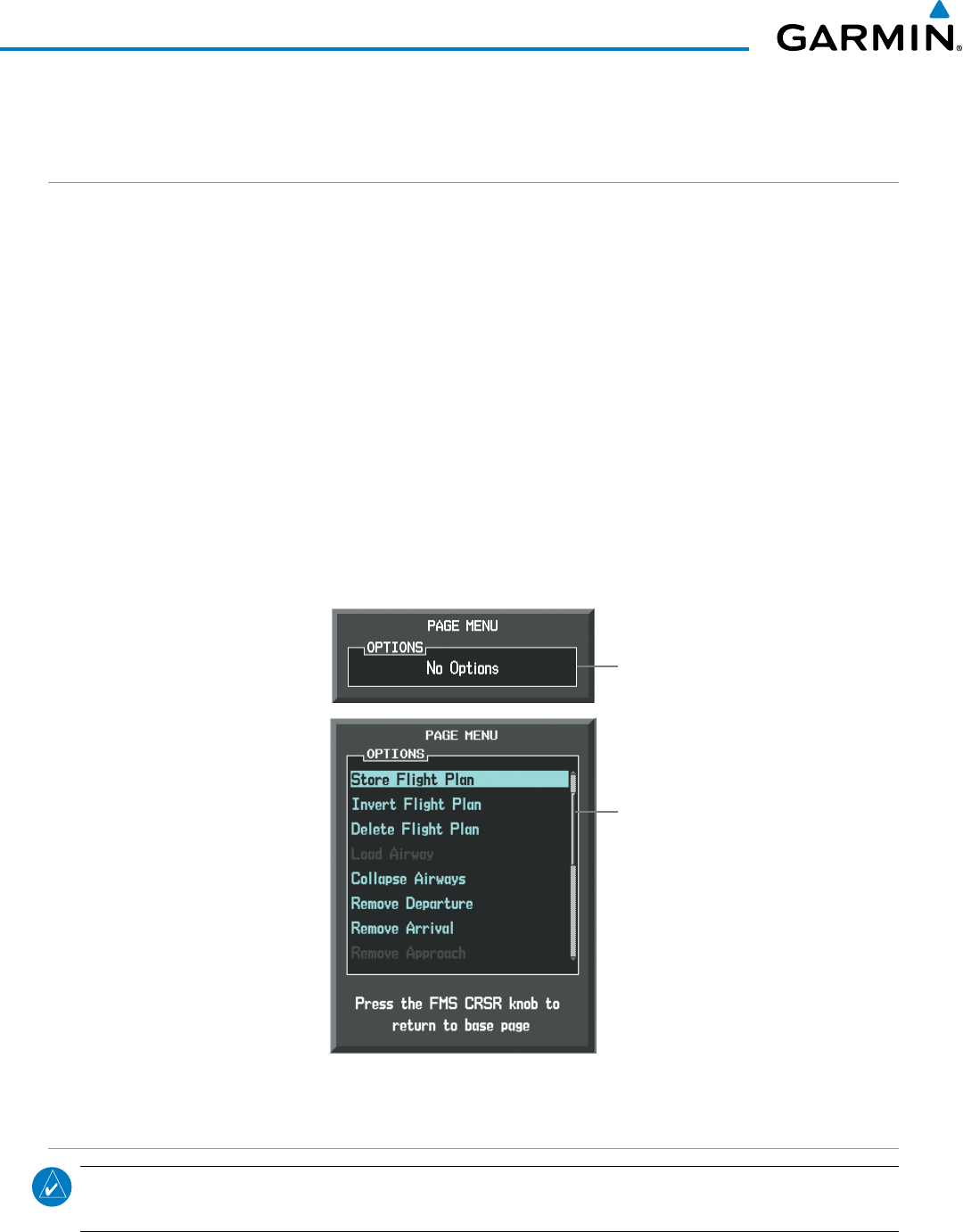
190-00928-04 Rev. A
Garmin G1000 Pilot’s Guide for the Beechcraft 200/B200 Series
34
SYSTEM OVERVIEW
1.7 ACCESSING G1000 FUNCTIONALITY
MENUS
The G1000 has a MENU Key that, when pressed, displays a context-sensitive list of options. This options list
allows the user to access additional features or make settings changes which specifically relate to the currently
displayed window/page. There is no all-encompassing menu. Some menus provide access to additional
submenus that are used to view, edit, select, and review options. Menus display ‘NO OPTIONS’ when there are
no options for the window/page selected. The main controls used in association with all window/page group
operations are described in section 1.3. Softkey selection does not display menus or submenus.
Navigating the Page Menu Window
1) Press the MENU Key to display the Page Menu Window.
2) Turn the FMS Knob to scroll through a list of available options (a scroll bar appears to the right of the window
when the option list is longer than the window).
3) Press the ENT Key to select the desired option.
4) The CLR Key may be pressed to remove the menu and cancel the operation. Pressing the FMS Knob also
removes the displayed menu.
Figure 1-23 Page Menu Examples
No Options with
NRST Window
Displayed on the
PFD
Options
with FPL
Window
Displayed
MFD PAGE GROUPS
NOTE: Refer to the Flight Management, Hazard Avoidance, and Additional Features sections for details on
specific pages.
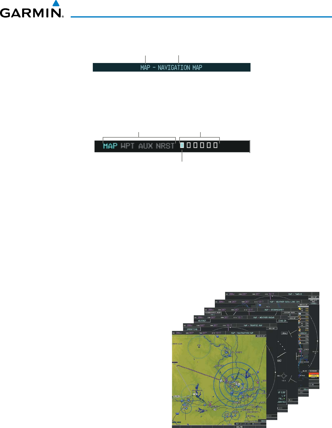
190-00928-04 Rev. A
Garmin G1000 Pilot’s Guide for the Beechcraft 200/B200 Series
35
SYSTEM OVERVIEW
The page group and active page title box are displayed in the upper right of the screen.
Page Group Active Page Title
Figure 1-24 Page Title Box
In the bottom right corner of the screen, the current page group, number of pages available in the group, and
placement of the current page within the group are indicated.
Figure 1-25 Page Group Icons
Page Groups
Selected Page
Pages in Current Group
The MFD displays information in four main page groups; specific pages within each group can vary depending
on the configuration of optional equipment.
Selecting a page using the FMS Knob
1) Turn the
large FMS
Knob until the desired page group is selected.
2)
Turn
the
small FMS
Knob until the desired page is selected.
There are also several pages (Airport Information and XM Information pages) which are selected first from
within a main page group with the FMS Knobs, then with the appropriate softkey at the bottom of the page. In
this case, the page remains set to the selected screen until a different screen softkey is pressed.
Figure 1-26 Map Pages
Map Page Group (MAP)
Navigation Map
Traffic Map
Weather Radar
Stormscope®(optional)
Weather Data Link (service optional)
TAWS
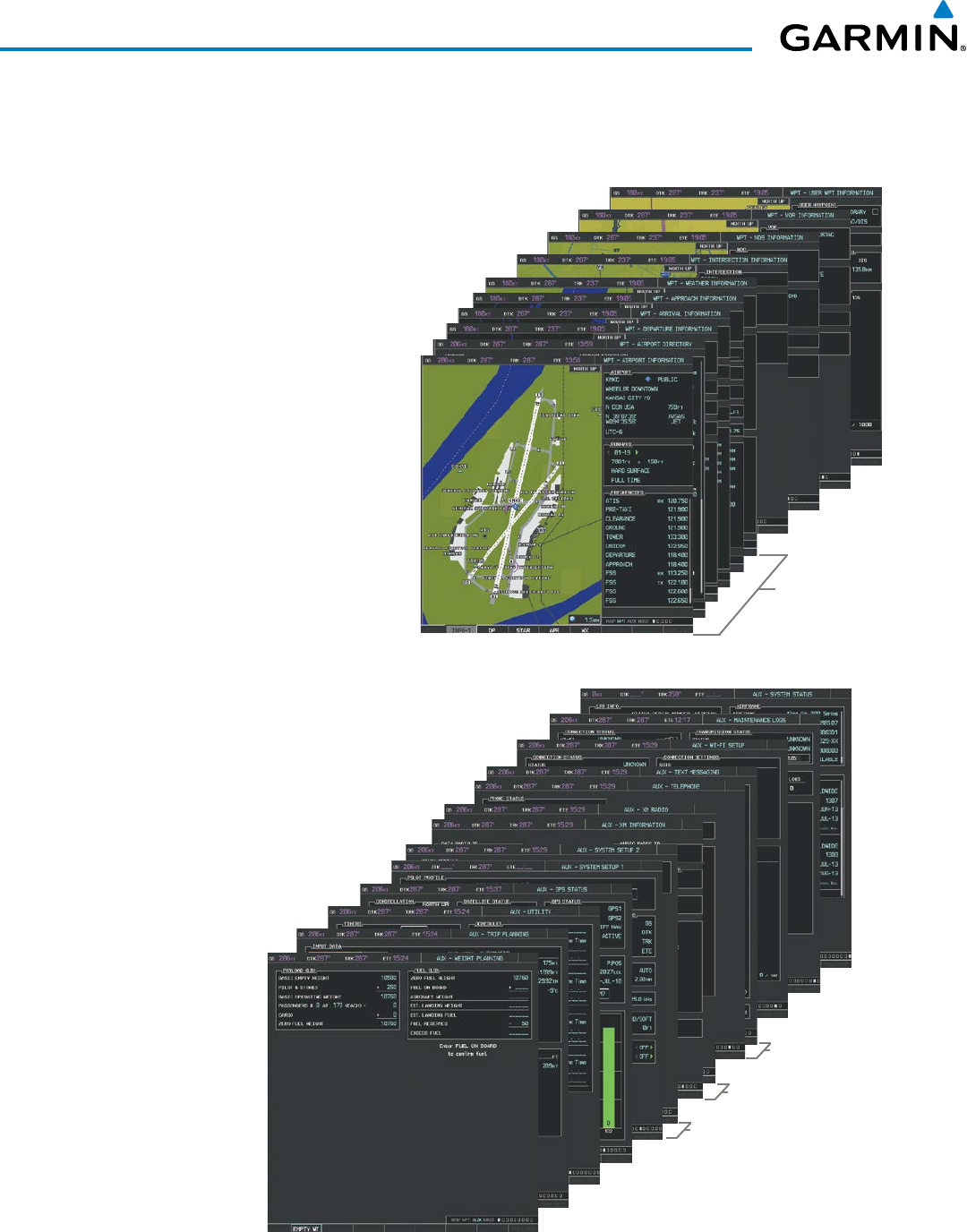
190-00928-04 Rev. A
Garmin G1000 Pilot’s Guide for the Beechcraft 200/B200 Series
36
SYSTEM OVERVIEW
Figure 1-27 Waypoint Pages
Airport/
Procedures/
Weather
Information
Pages
Waypoint Page Group (WPT)
Airport/Procedures/Weather Information Pages
- Airport Information
(INFO-1 Softkey)
- Airport Directory Information
(INFO-2 Softkey)
- Departure Information
(DP Softkey)
- Arrival Information
(STAR Softkey)
- Approach Information
(APR Softkey)
- Weather Information (optional)
(WX Softkey)
Intersection Information
NDB Information
VOR Information
User Waypoint Information
Figure 1-28 Auxiliary Pages
Auxiliary Page Group (AUX)
Weight Planning
Trip Planning
Utility
GPS Status
System Setup 1/2
XM Satellite pages
- XM Information
(INFO Softkey)
- XM Radio
(RADIO Softkey)
Satellite Comm pages
- Telephone
(TEL Softkey)
- Text Messaging
(SMS Softkey)
Wi-Fi Setup
Maintenance Logs
System Status
XM Satellite
Pages
System Setup
Pages
SatComm
Pages
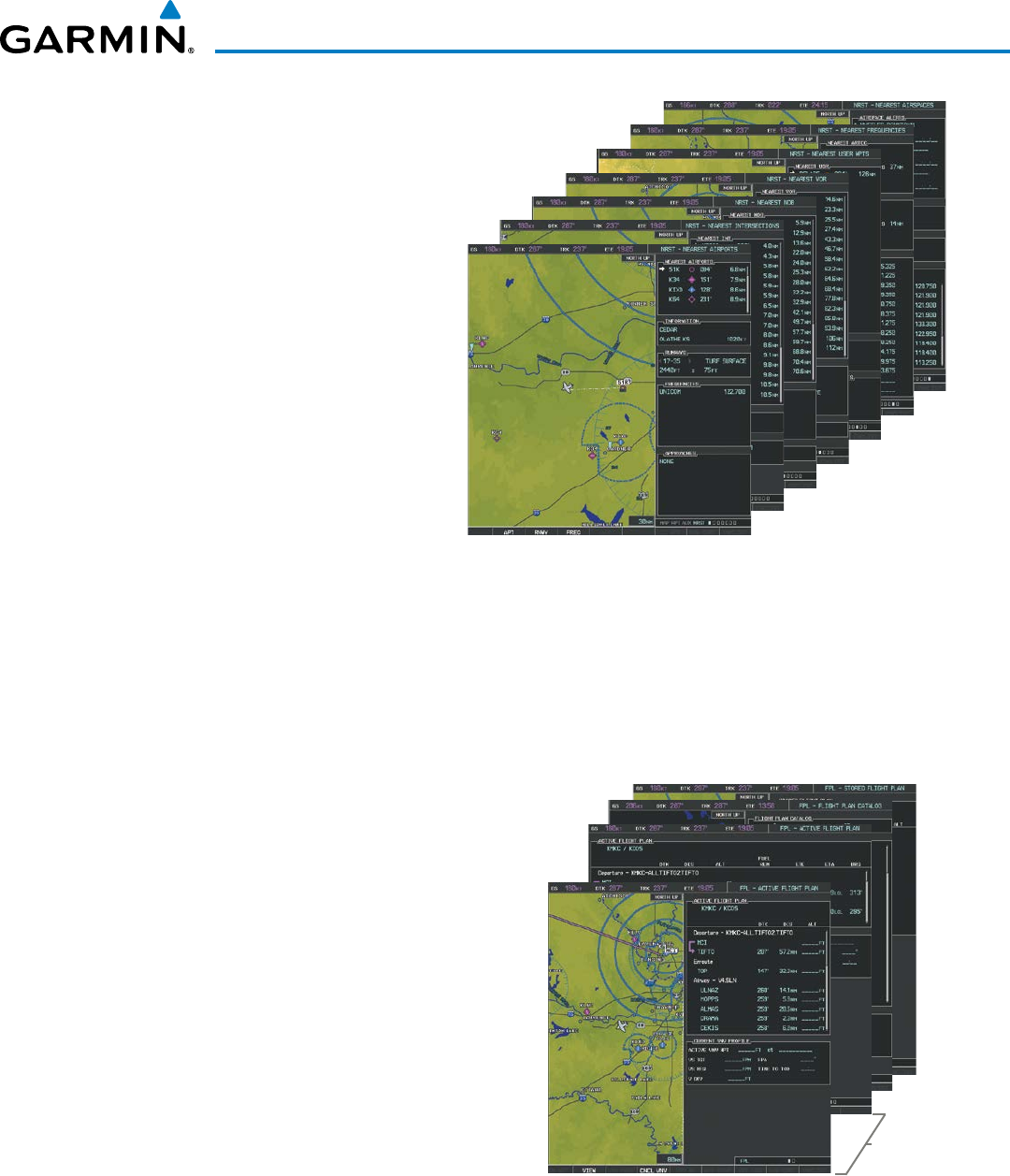
190-00928-04 Rev. A
Garmin G1000 Pilot’s Guide for the Beechcraft 200/B200 Series
37
SYSTEM OVERVIEW
Figure 1-29 Nearest Pages
Nearest Page Group (NRST)
Nearest Airports
Nearest Intersections
Nearest NDB
Nearest VOR
Nearest User Waypoints
Nearest Frequencies
Nearest Airspaces
In addition to the main page groups accessed exclusively using the FMS Knobs, there are pages for flight
planning (FPL) and loading procedures (PROC) which are accessed by a dedicated key. In some instances,
softkeys may be used to access the Procedure Pages.
The Flight Plan Pages are accessed using the FPL Key. Main pages within this group are selected by turning
the small FMS Knob.
Figure 1-30 Flight Plan Pages
Flight Plan Pages (FPL)
Active Flight Plan
- Wide View, Narrow View (VIEW
Softkey)
Flight Plan Catalog
Stored Flight Plan (via NEW Softkey on
Flight Plan Catalog Page)
Narrow and
Wide View
The Procedure pages may be accessed at any time on the MFD by pressing the PROC Key. A menu is
initialized, and when a departure, approach, or arrival is selected, the appropriate Procedure Loading Page is
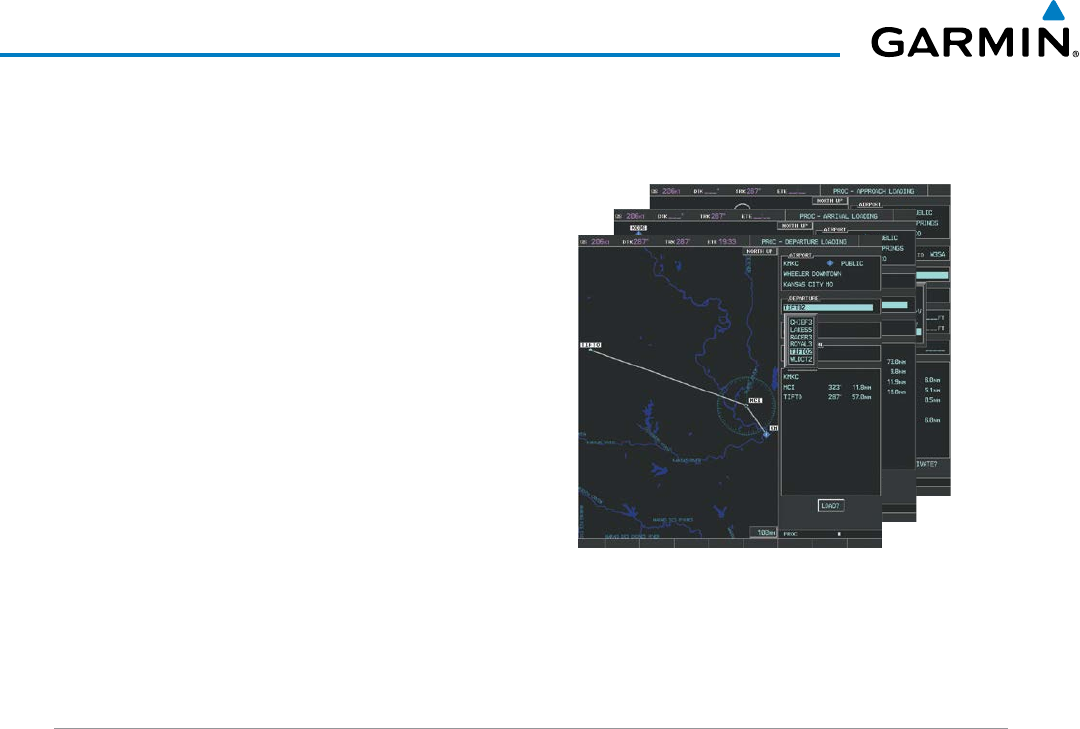
190-00928-04 Rev. A
Garmin G1000 Pilot’s Guide for the Beechcraft 200/B200 Series
38
SYSTEM OVERVIEW
opened. Turning the FMS Knob does not scroll through the Procedure pages (note the single page icon in the
lower right corner).
Figure 1-31 Procedure Pages
Procedure Pages (PROC)
Departure Loading
Arrival Loading
Approach Loading
For some of these pages (Airport Information pages, XM Satellite pages, Procedure pages), the title of the page
may change while the page icon remains the same.
MFD SYSTEM PAGES
In the Auxiliary (AUX) Page Group, there are three system pages: System Setup 1, System Setup 2, and System
Status. The System Setup pages allows management of various system parameters, while the System Status Page
displays the status of all G1000 system LRUs.
SYSTEM SETUP PAGES
The System Setup pages allows management of the pilot profiles and the following system parameters:
• Time display format (local or UTC )
• Displayed measurement units
• Barometric Transition Alert
(see the Flight Instruments Section)
• Airspace alerts
(see the Flight Management Section)
• Arrival alert
• Audio alert voice
• Flight Director Format
(see the Flight Instruments Section)
• MFD Data Bar (Navigation Status Box) fields
(see the Flight Management Section)
• GPS Course Deviation Indicator (CDI) range
(see the Flight Instruments Section)
• COM transceiver channel spacing
(see the Audio Panel and CNS Section)
• Displayed nearest airports
(see the Flight Management Section)
• CDI/Baro Synchronization
(see the Flight Instruments Section)
• Stability & Protection
(see the AFCS & Additional Features Sections)
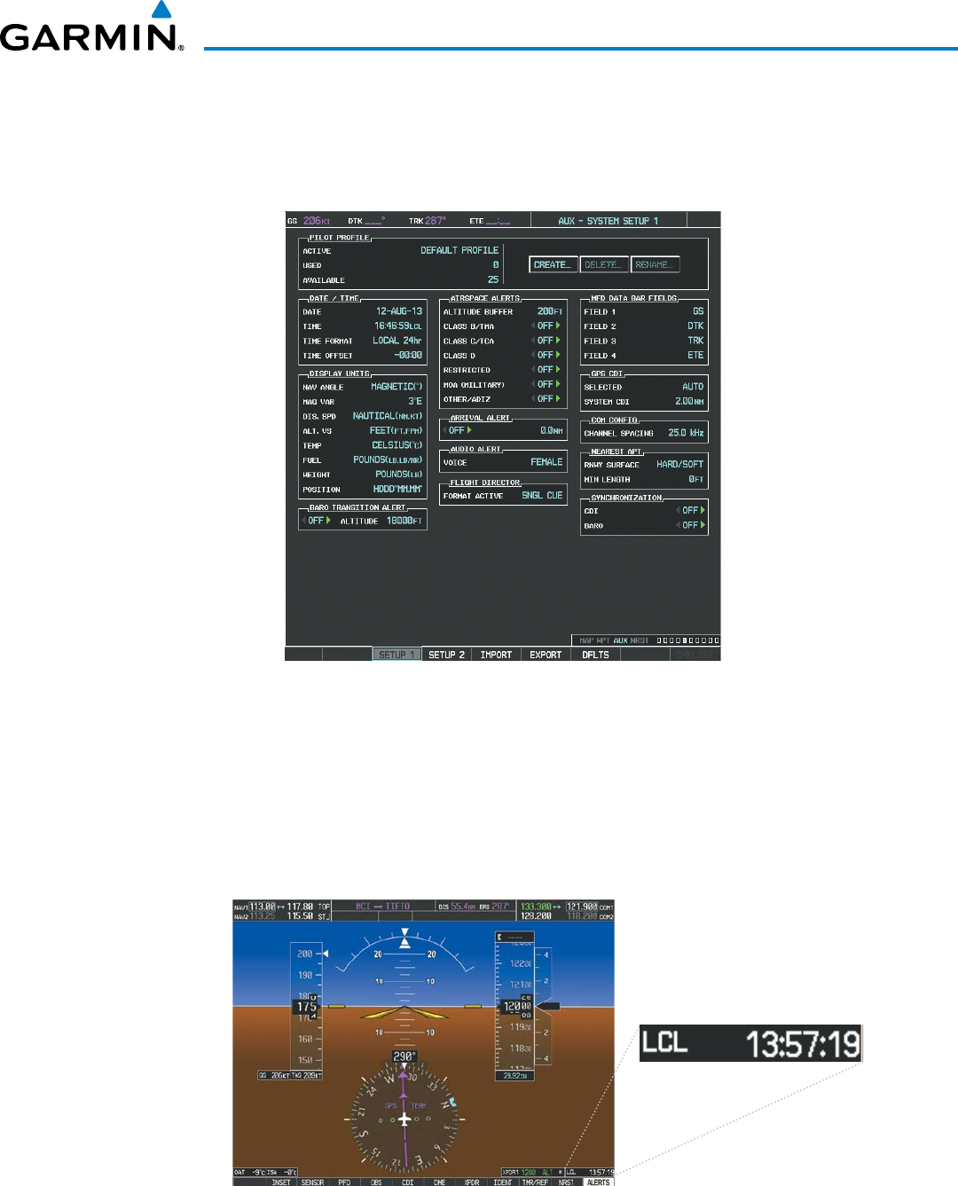
190-00928-04 Rev. A
Garmin G1000 Pilot’s Guide for the Beechcraft 200/B200 Series
39
SYSTEM OVERVIEW
Restoring system setup defaults:
1) Select the AUX - System Setup Page.
2) Select the DFLTS Softkey; or press the MENU Key, highlight ‘Restore Defaults’, and press the ENT Key.
Figure 1-34 System Setup Page
Date/tiMe
The G1000 obtains the current Universal Coordinated Time (UTC) date and time directly from the GPS
satellite signals (shown on the AUX - GPS Status Page). System time (displayed in the lower right corner of
the PFD) can be displayed in three formats: local 12-hr, local 24-hr, or UTC. Local time is set by adding/
subtracting an offset (hours:minutes) to/from UTC.
Figure 1-33 System Time (Local 24-hr Format)
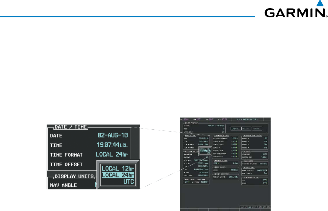
190-00928-04 Rev. A
Garmin G1000 Pilot’s Guide for the Beechcraft 200/B200 Series
40
SYSTEM OVERVIEW
Configuring the system time:
1) Select the AUX - System Setup Page.
2) Press the FMS Knob to activate the cursor.
3) Turn the large FMS Knob to highlight the ‘Time Format’ field.
4) Turn the small FMS Knob to select the desired format and press the ENT Key to confirm selection. The ‘Time
Offset’ field is highlighted.
5) Use the FMS Knob to enter the desired time offset (±HH:MM) and press the ENT Key to confirm selection.
Figure 1-34 Date/Time Settings (System Setup Page)
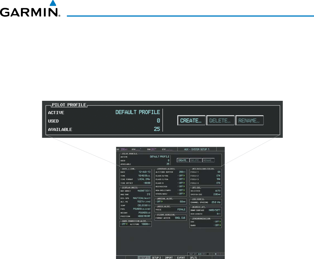
190-00928-04 Rev. A
Garmin G1000 Pilot’s Guide for the Beechcraft 200/B200 Series
41
SYSTEM OVERVIEW
Pilot PRoFileS
System settings may be saved under a pilot profile. When the system is powered on, the last selected
pilot profile is shown on the MFD Power-up Splash Screen (Figure 1-8). The G1000 can store up to 25
profiles; the currently active profile, the amount of memory used, and the amount of memory available are
shown at the top of the System Setup Page in the box labeled ‘Pilot Profile’. From here, pilot profiles may be
created, selected, renamed, or deleted. Pilot profiles may also be exported from the system to an SD card,
or imported from an SD card into the system.
Figure 1-35 Pilot Profile Management (System Setup Page)
Creating a profile:
1) Select the AUX - System Setup Page.
2) Press the FMS Knob momentarily to activate the flashing cursor.
3) Turn the large FMS Knob to highlight ‘CREATE’ in the Pilot Profile Box.
4) Press the ENT Key. A ‘Create Profile’ window is displayed.
5) Use the FMS Knob to enter a profile name up to 16 characters long and press the ENT Key. Pilot profile names
cannot begin with a blank as the first letter.
6) In the next field, use the small FMS Knob to select the desired settings upon which to base the new profile.
Profiles can be created based on Garmin factory defaults, default profile settings (initially based on Garmin
factory defaults unless edited by the pilot), or current system settings.
7) Press the ENT Key.
8) With ‘CREATE’ highlighted, press the ENT Key to create the profile
Or:

190-00928-04 Rev. A
Garmin G1000 Pilot’s Guide for the Beechcraft 200/B200 Series
42
SYSTEM OVERVIEW
Use the large FMS Knob to select ‘CREATE and ACTIVATE’ and press the ENT Key to activate the new profile.
9) To cancel the process, select ‘CANCEL’ with the large FMS Knob and press the ENT Key.
Selecting an active profile:
1) Select the AUX - System Setup Page.
2) Press the FMS Knob momentarily to activate the flashing cursor.
3) Turn the large FMS Knob to highlight the active profile field in the Pilot Profile Box.
4) Turn the small FMS Knob to display the pilot profile list and highlight the desired profile.
5) Press the ENT Key. The G1000 loads and displays the system settings for the selected profile.
Renaming a profile:
1) Select the AUX - System Setup Page.
2) Press the FMS Knob momentarily to activate the flashing cursor.
3) Turn the large FMS Knob to highlight ‘RENAME’ in the Pilot Profile Box.
4) Press the ENT Key.
5) In the ‘Rename Profile’ window, turn the FMS Knob to select the profile to rename.
6) Press the ENT Key.
7) Use the FMS Knob to enter a new profile name up to 16 characters long and press the ENT Key.
8) With ‘RENAME’ highlighted, press the ENT Key.
9) To cancel the process, use the large FMS Knob to select ‘CANCEL’ and press the ENT Key.
Deleting a profile:
1) Select the AUX - System Setup Page.
2) Press the FMS Knob momentarily to activate the flashing cursor.
3) Turn the large FMS Knob to highlight ‘DELETE’ in the Pilot Profile Box.
4) Press the ENT Key.
5) In the ‘Delete Profile’ window, turn the FMS Knob to select the profile to delete.
6) Press the ENT Key.
7) With ‘DELETE’ highlighted, press the ENT Key.
8) To cancel the process, use the large FMS Knob to select ‘CANCEL’ and press the ENT Key.
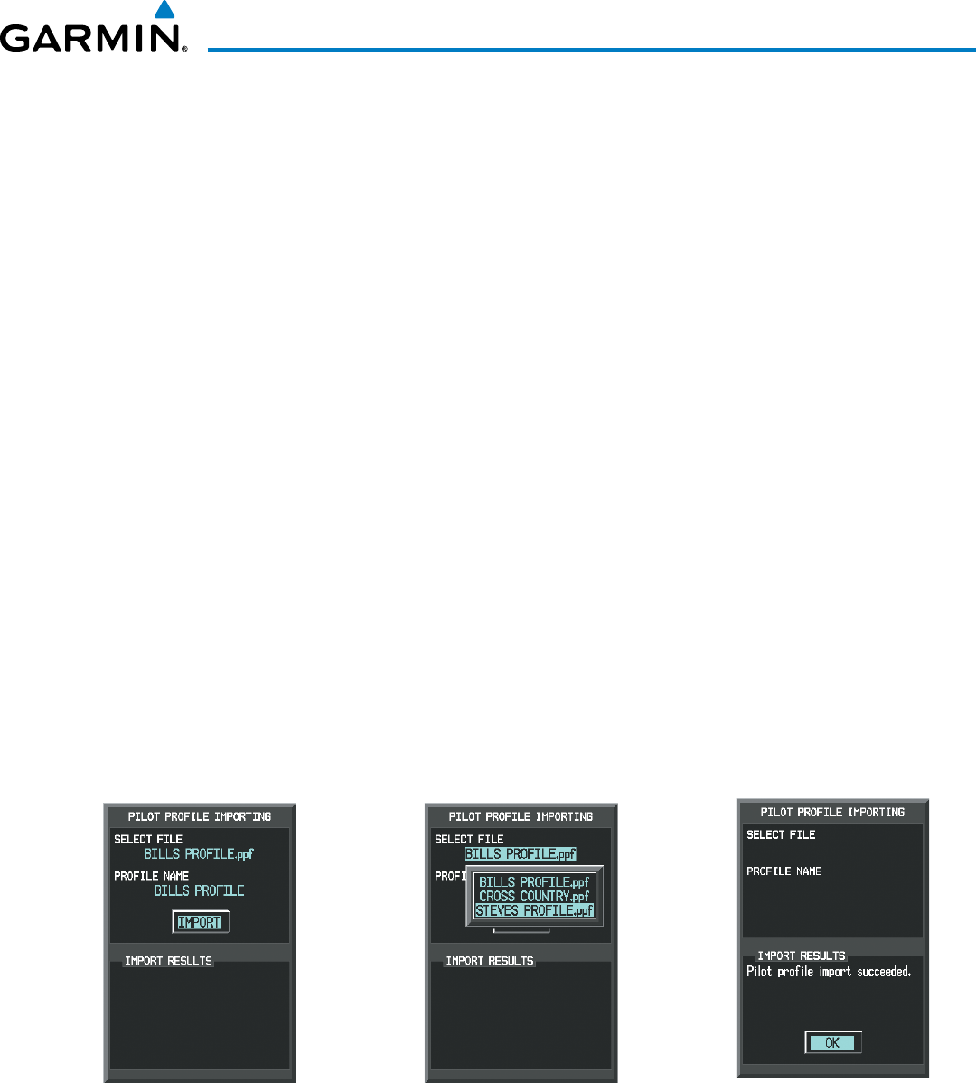
190-00928-04 Rev. A
Garmin G1000 Pilot’s Guide for the Beechcraft 200/B200 Series
43
SYSTEM OVERVIEW
Importing a profile from an SD card:
1) Insert an SD card containing the pilot profile(s) into the top card slot on the MFD.
2) Turn the FMS Knob to select the AUX - System Setup Page.
3) Select the IMPORT Softkey.
Or:
a) Press the MENU Key.
b) Turn the FMS Knob to highlight ‘Import Pilot Profile’ and press the ENT Key.
4) The system displays the Pilot Profile Importing window with ‘IMPORT’ highlighted. To change the selected
profile to be imported from the SD card (shown as ‘SELECT FILE’), turn the large FMS Knob to highlight the
profile file name, then turn the small FMS Knob to highlight a profile from the list, and press the ENT Key.
5) If desired, the profile name to be used after profile has been imported can be changed by turning the FMS
Knob to highlight the ‘PROFILE NAME’ field, then use the large and small FMS Knobs to enter the name, and
press the ENT Key. Imported profile names cannot begin with a blank space or be named ‘DEFAULT’, ‘GARMIN
DEFAULTS’ or ‘DEFAULT SETTINGS’.
6) With ‘IMPORT’ highlighted, press the ENT Key.
7) If the imported profile name is the same as an existing profile on the system, the system displays an ‘Overwrite
existing file? OK or CANCEL’ prompt. Press the ENT Key to replace profile on the system with the profile
imported from the SD card, or turn the FMS Knob to highlight ‘CANCEL’ and press the ENT Key to return to the
Pilot Profile Importing window.
8) If successful, the system displays ‘Pilot profile import succeeded.’ in the IMPORT RESULTS window below. With
‘OK’ highlighted, press the ENT or CLR Keys or press the FMS Knob to return to the AUX - System Setup Page.
The imported profile becomes the active profile.
Pilot Profile Importing and Import
Results Window
Pilot Profiles Available for Import from
SD Card (‘STEVE’S PROFILE’ Selected)
Import Successful
Figure 1-36 Pilot Profile Import (AUX - System Setup Page)
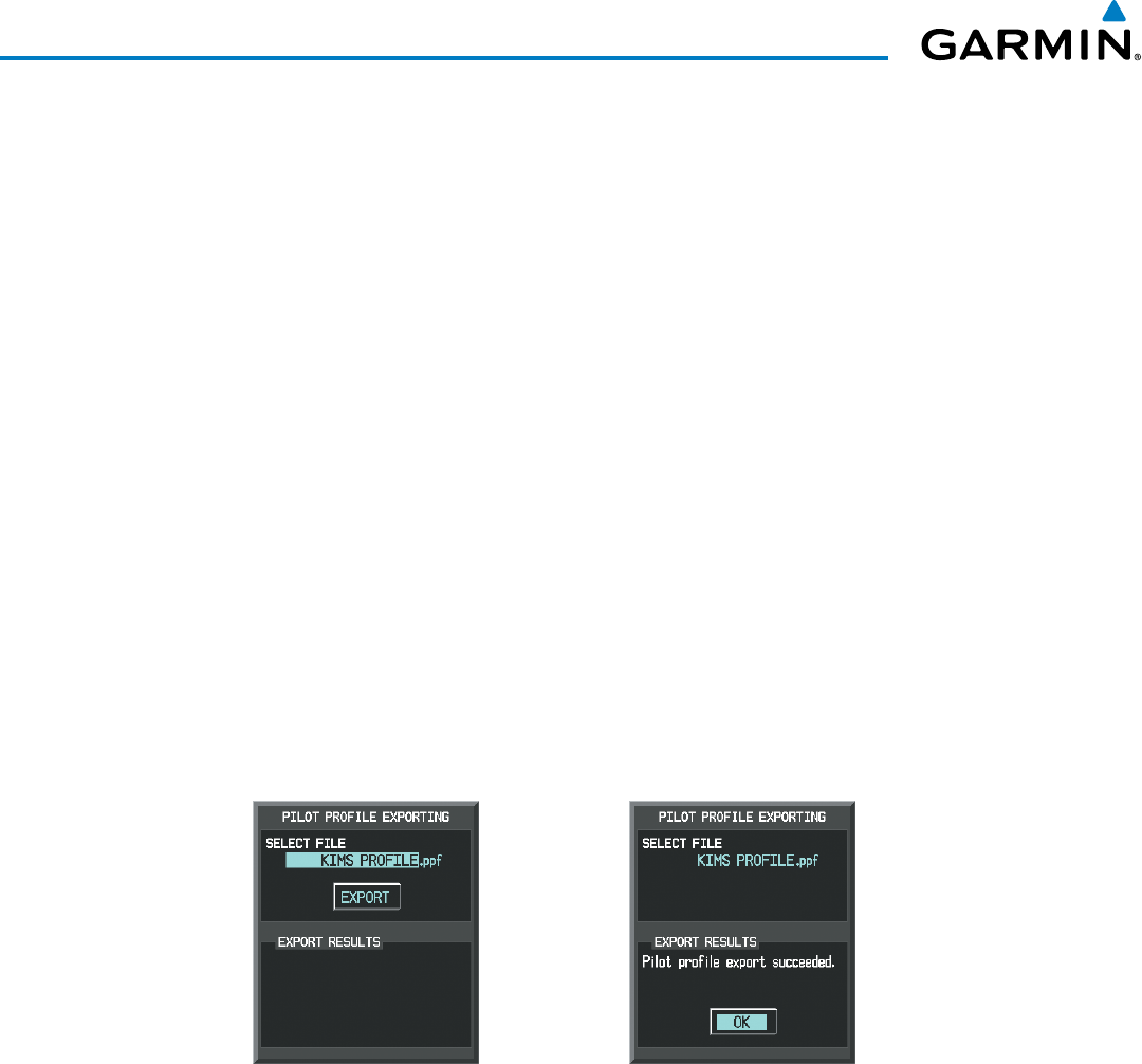
190-00928-04 Rev. A
Garmin G1000 Pilot’s Guide for the Beechcraft 200/B200 Series
44
SYSTEM OVERVIEW
Exporting a profile to an SD card:
1) Insert the SD card for storing the Pilot Profile into the top card slot on the MFD.
2) Turn the FMS Knob to select the AUX - System Setup Page.
3) If necessary, activate the desired pilot profile to export. Only the currently active Pilot Profile can be exported.
4) Select the EXPORT Softkey. The system displays the Pilot Profile Exporting window.
Or:
a) Press the MENU Key.
b) Turn the FMS Knob to highlight ‘Export Pilot Profile’ and press the ENT Key.
5) To export the pilot profile using the current supplied name, press the ENT Key with ‘EXPORT’ highlighted. To
change the profile file name turn the large FMS Knob to highlight the ‘SELECT FILE’ field, then enter the new
name with the large and small FMS Knobs, then press the ENT Key. Then press the ENT Key with ‘EXPORT’
highlighted.
6) If the profile name to be exported is the same as an existing profile file name on the SD card, the system displays
an ‘Overwrite existing file? OK or CANCEL’ prompt. Press the ENT Key to replace the profile on the SD card
with the profile to be exported, or turn the FMS Knob to highlight ‘CANCEL’ and press the ENT Key to return to
the Pilot Profile Exporting window without exporting the profile.
7) If successful, the EXPORT RESULTS window displays ‘Pilot profile export succeeded.’ With ‘OK’ highlighted,
press the ENT or CLR Keys, or press the FMS Knob to return to the AUX - System Setup Page.
Pilot Profile Exporting Window, Enter a
Name to Use for Exported Profile
Export Successful
Figure 1-37 Pilot Profile Export on the AUX - System Setup Page

190-00928-04 Rev. A
Garmin G1000 Pilot’s Guide for the Beechcraft 200/B200 Series
45
SYSTEM OVERVIEW
DiSPlay unitS
Units in which various quantities are displayed on the G1000 screens are listed on the System Setup Page.
The Navigation Angle reference, the Temperature units, and the Position units can be set from here.
Category Settings Affected Quantities Exceptions
Navigation Angle Magnetic (North)*
True (North)
User
Heading
Course
Bearing
Track
Desired Track
Wind direction (Trip Planning Page)
Distance and Speed** Metric
Nautical*
Crosstrack error (HSI)
Bearing distances (information windows)
DME distance (information window)
Flight plan distances
Map ranges
DIS, GS, TAS, XTK fields (Navigation Status Box)
All distances on MFD
Altitude buffer distance (System Setup)
Arrival Alert trigger distance (System Setup)
All speeds on MFD
Airspeed Indicator
True Airspeed (PFD)
Wind speed vector
Map range (Traffic Page, Terrain
Proximity/TAWS Page)
CDI scaling (System Setup)
Fuel range calculation (EIS)
Altitude and Vertical
Speed***
Feet All altitudes on MFD
All elevations on MFD
Altimeter
Vertical Speed Indicator
VNV altitudes (Active Flight Plan)
Temperature Celsius*
Fahrenheit
All temperatures on PFD
Total Air Temperature (Trip Planning Page)
Engine Indication System (EIS)
Fuel and Fuel
Flow***
Pounds Fuel parameters (Trip Planning Page) Engine Indication System (EIS)
Weight** Pounds*
Kilograms
N/A N/A
Position HDDD°MM.MM’*
HDDD°MM’SS.S”
MGRS
UTM/UPS
All positions N/A
* Default setting
** Contact a Garmin-authorized service center to change this setting
*** Not configurable
Table 1-1 Display Units Settings (System Setup Page)
Changing a display unit setting
1) While on the System Setup Page, press the FMS Knob momentarily to activate the flashing cursor.
2) Turn the large FMS Knob to highlight the desired field in the Display Units Box.
3) Turn the small FMS Knob to select the desired units.
4) Press the ENT Key. Press the CLR Key to cancel the action without changing the units.
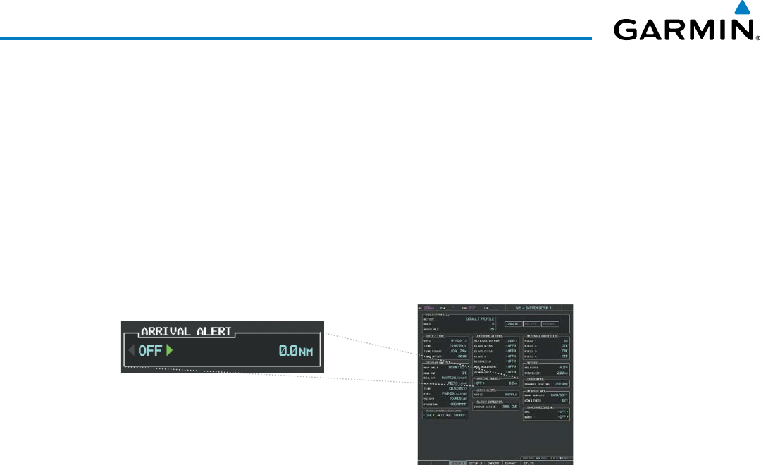
190-00928-04 Rev. A
Garmin G1000 Pilot’s Guide for the Beechcraft 200/B200 Series
46
SYSTEM OVERVIEW
aRRival aleRtS
The Arrival Alert Box on the System Setup Page allows the Alerts Window arrival alerts to be turned
ON/OFF, and the alert trigger distance (up to 99.9 units) set for alerts in the Alerts Window and the
PFD Navigation Status Box. An arrival alert can be set to notify the pilot with a message upon reaching
a user-specified distance from the final destination (the direct-to waypoint or the last waypoint in a flight
plan). When Arrival Alerts is set to ON, and the set distance is reached, an “Arrival at waypoint” message
is displayed in the PFD Navigation Status Box, and a “WPT ARRIVAL - Arriving at waypoint - [xxxx]” is
displayed in the Alerts Window. When Arrival Alerts is set to OFF, only the PFD Navigation Status Box
message “Arriving at waypoint” is displayed, and it is displayed when the time to the final destination is
approximately ten seconds.
Figure 1-36 Arrival Alert Settings (System Setup Page)
Enabling/disabling the Alerts Window arrival alert:
1) Use the FMS Knob to select the AUX - System Setup Page.
2) Press the FMS Knob momentarily to activate the flashing cursor.
3) Turn the large FMS Knob to select the ON/OFF field in the Arrival Alert Box.
4) Turn the small FMS Knob clockwise to turn the airspace alert ON or counterclockwise to turn the alert OFF.
Changing the arrival alert trigger distance:
1) Use the FMS Knob to select the AUX - System Setup Page.
2) Press the FMS Knob momentarily to activate the flashing cursor.
3) Turn the large FMS Knob to highlight the distance field in the Arrival Alert Box.
4) Use the FMS Knob to enter a trigger distance and press the ENT Key.
auDio aleRtS
The Audio Alert Box on the System Setup Page allows the audio alert voice to be set to male or female.
Changing the audio alert voice
1) While on the System Setup Page, press the FMS Knob momentarily to activate the flashing cursor.
2) Turn the large FMS Knob to highlight the voice in the Audio Alert Box.
3) Turn the small FMS Knob to display and highlight the desired voice and press the ENT Key.
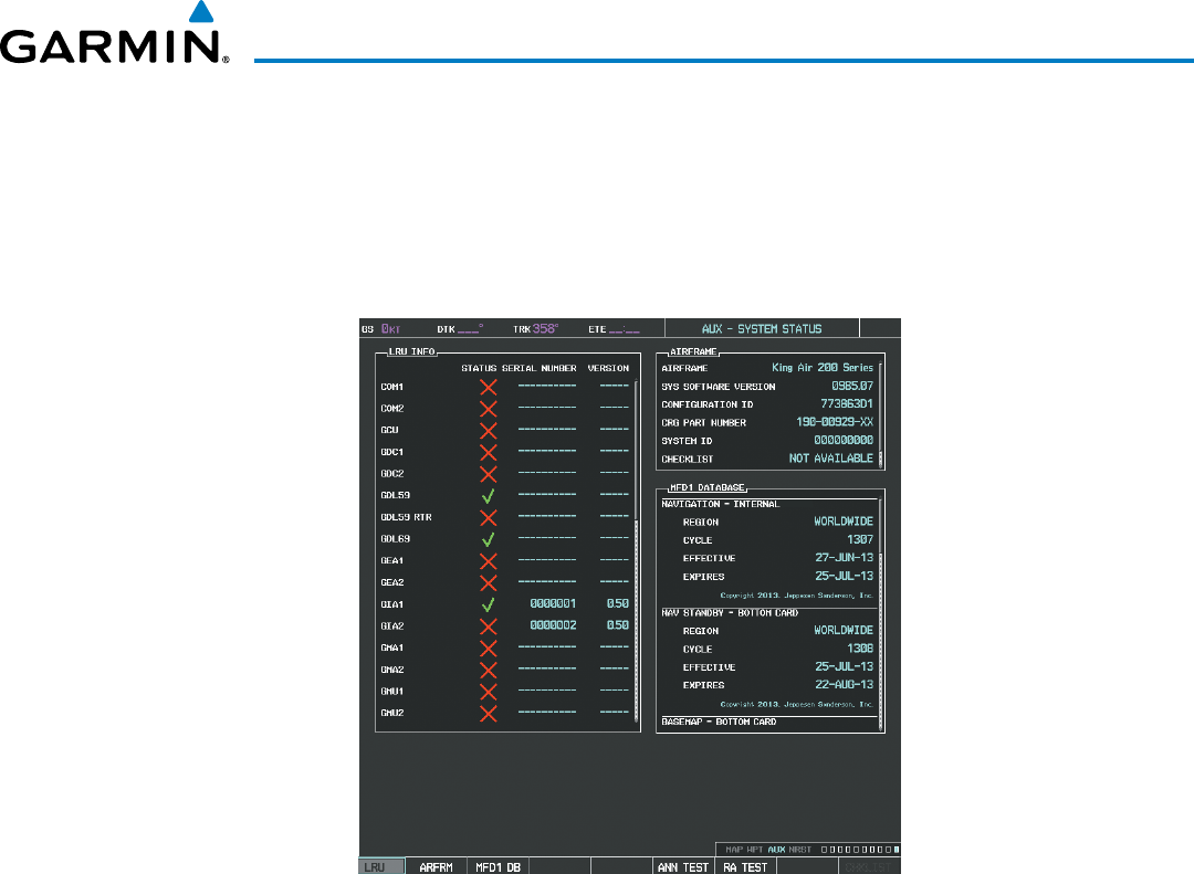
190-00928-04 Rev. A
Garmin G1000 Pilot’s Guide for the Beechcraft 200/B200 Series
47
SYSTEM OVERVIEW
SYSTEM STATUS PAGE
The System Status Page displays the status and software version numbers for all detected system LRUs.
Pertinent information on all system databases is also displayed. Active LRUs are indicated by green check
marks and failed LRUs are indicated by red “X”s. Failed LRUs should be noted and a service center or Garmin
dealer informed.
Figure 1-37 Example System Status Page
The LRU and ARFRM Softkeys on the System Status Page select the applicable list (LRU INFO or AIRFRAME
window) through which the FMS Knob can be used to scroll information within the selected window.
Selecting the MFD1 DB Softkey (label background changes to grey indicting the softkey is selected) places
the cursor in the database window. Use the FMS Knob to scroll through database information for the MFD.
Selecting the softkey again will change the softkey label to PFD1 DB. PFD 1 database information is now
displayed in the database window. Selecting the softkey a third time will change the softkey label to PFD2
DB. PFD 2 database information is now displayed in the database window.
The ANN TEST Softkey, when selected, causes an annunciation test tone to be played.
The RA TEST Softkey, when selected, initiates the Radar Altimeter test mode. For more information, see
the Flight Instruments section.
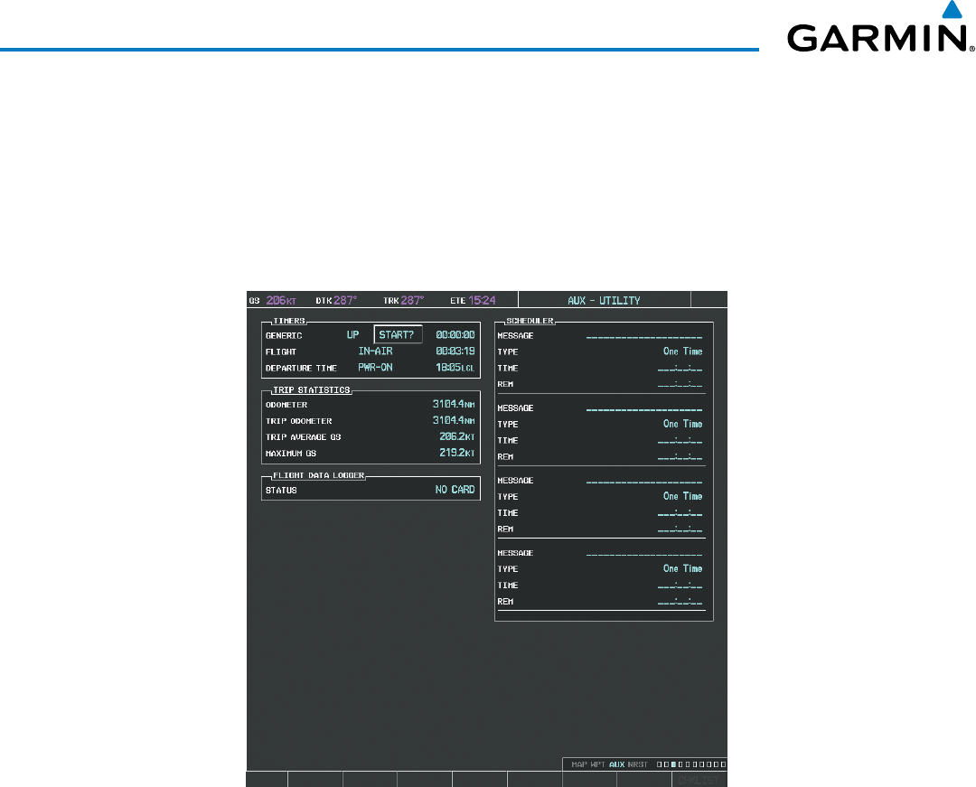
190-00928-04 Rev. A
Garmin G1000 Pilot’s Guide for the Beechcraft 200/B200 Series
48
SYSTEM OVERVIEW
UTILITY PAGE
For flight planning purposes, timers, trip statistics, and a scheduler feature are provided on the AUX -
Utility Page. The timers available include a stopwatch-like generic timer, a total time in flight timer, and a
record of the time of departure. Trip statistics—odometer, trip odometer, and average trip and maximum
groundspeeds—are displayed from the time of the last reset. Refer to the Additional Features section for a
discussion on the Scheduler feature.
Figure 1-38 Utility Page
tiMeRS
The G1000 timers available include:
• Stopwatch-like generic timers (available from the PFD Timer/References Window and on the MFD AUX
- Utility Page)
• Total-time-in-flight timer (MFD AUX - Utility Page)
• Time since departure (MFD AUX - Utility Page)
The generic timer can be set to count up or down from a specified time (HH:MM:SS). When the
countdown on the timer reaches zero the digits begin to count up from zero. If the timer is reset before
reaching zero on a countdown, the digits are reset to the initial value. If the timer is counting up when
reset, the digits return to zero.
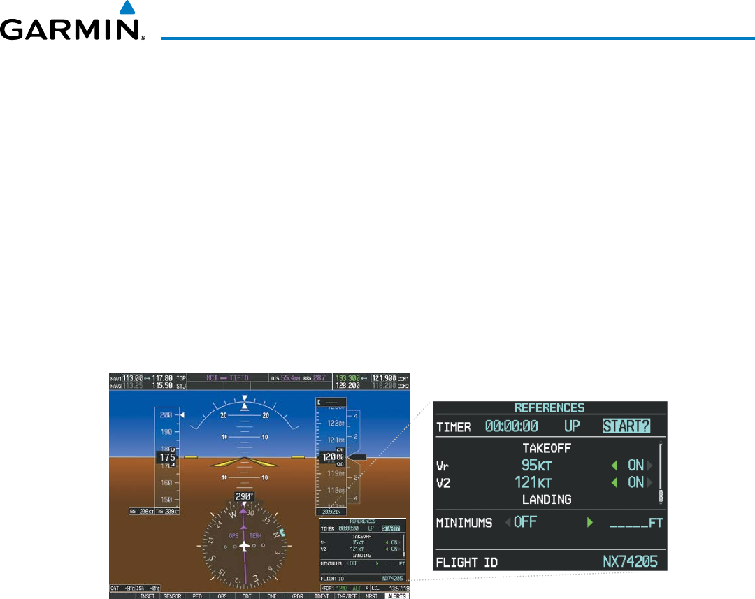
190-00928-04 Rev. A
Garmin G1000 Pilot’s Guide for the Beechcraft 200/B200 Series
49
SYSTEM OVERVIEW
Setting the generic timer (PFD):
1) Press the
TMR/REF
Softkey.
2) Turn the
large FMS
Knob to select the timer field (HH:MM:SS).
3) Use the FMS Knob to enter the desired time and press the
ENT
Key.
4) With the UP/DN field highlighted, turn the
small FMS
Knob to select the timer counting direction (UP/DN) and
press the
ENT
Key.
6) With ‘START?’ highlighted, press the
ENT
Key to start the timer. The field changes to ‘STOP?’.
7) To stop the timer, press the ENT Key with ‘STOP?’ highlighted. The field changes to ‘RESET?’.
8) To reset the timer, press the ENT Key with ‘RESET?’ highlighted. The field changes back to ‘START?’ and the
digits are reset.
9) To remove the window, press the
CLR
Key or the
TMR/REF
Softkey.
Figure 1-39 Generic Timer (PFD Timer/References Window)
Setting the generic timer (MFD AUX - Utility Page)
1) Use the FMS Knob to select the AUX - Utility Page.
2) Press the FMS Knob momentarily to activate the flashing cursor.
3) Turn the small FMS Knob to select the timer counting direction (UP/DN) and press the ENT Key.
4) If a desired starting time is desired:
a) Use the large FMS Knob to highlight the HH:MM:SS field.
b) Use the FMS Knob to enter the desired time and press the
ENT
Key.
5) Turn the
large FMS
Knob to highlight ‘START?’ and press the
ENT
Key to start the timer. The field changes to
‘STOP?’.
6) To stop the timer, press the ENT Key with ‘STOP?’ highlighted. The field changes to ‘RESET?’.
7) To reset the timer, press the ENT Key with ‘RESET?’ highlighted. The field changes back to ‘START?’ and the
digits are reset.
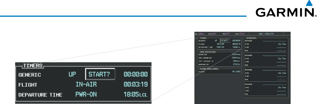
190-00928-04 Rev. A
Garmin G1000 Pilot’s Guide for the Beechcraft 200/B200 Series
50
SYSTEM OVERVIEW
Figure 1-40 Timers (MFD AUX - Utility Page)
The flight timer can be set to count up from zero starting at system power-up or from the time that the
aircraft lifts off; the timer can also be reset to zero at any time.
Setting the flight timer starting criterion
1) Use the FMS Knob to select the AUX - Utility Page.
2) Press the FMS Knob momentarily to activate the flashing cursor.
3) Turn the large FMS Knob to highlight the field next to the flight timer.
4) Turn the
small FMS
Knob to select the starting criterion (PWR-ON or IN-AIR) and press the
ENT
Key.
Resetting the flight timer
1) Use the FMS Knob to select the AUX - Utility Page.
2) Press the
MENU
Key.
3) With ‘Reset Flight Timer’ highlighted, press the
ENT
Key.
The G1000 records the time at which departure occurs, depending on whether the pilot prefers the time
to be recorded from system power-up or from aircraft lift off. The displayed departure time can also be reset
to display the current time at the point of reset. The format in which the time is displayed is controlled
from the System Setup Page.
Setting the departure timer starting criterion
1) Use the FMS Knob to select the AUX - Utility Page.
2) Press the FMS Knob momentarily to activate the flashing cursor.
3) Turn the large FMS Knob to highlight the field next to the departure time.
4) Turn the
small FMS
Knob to select the starting criterion (PWR-ON or IN-AIR) and press the
ENT
Key.
Resetting the departure time
1) Use the FMS Knob to select the AUX - Utility Page.
2) Press the
MENU
Key.
3) Use the FMS Knob to highlight ‘Reset Departure Time’ and press the
ENT
Key.
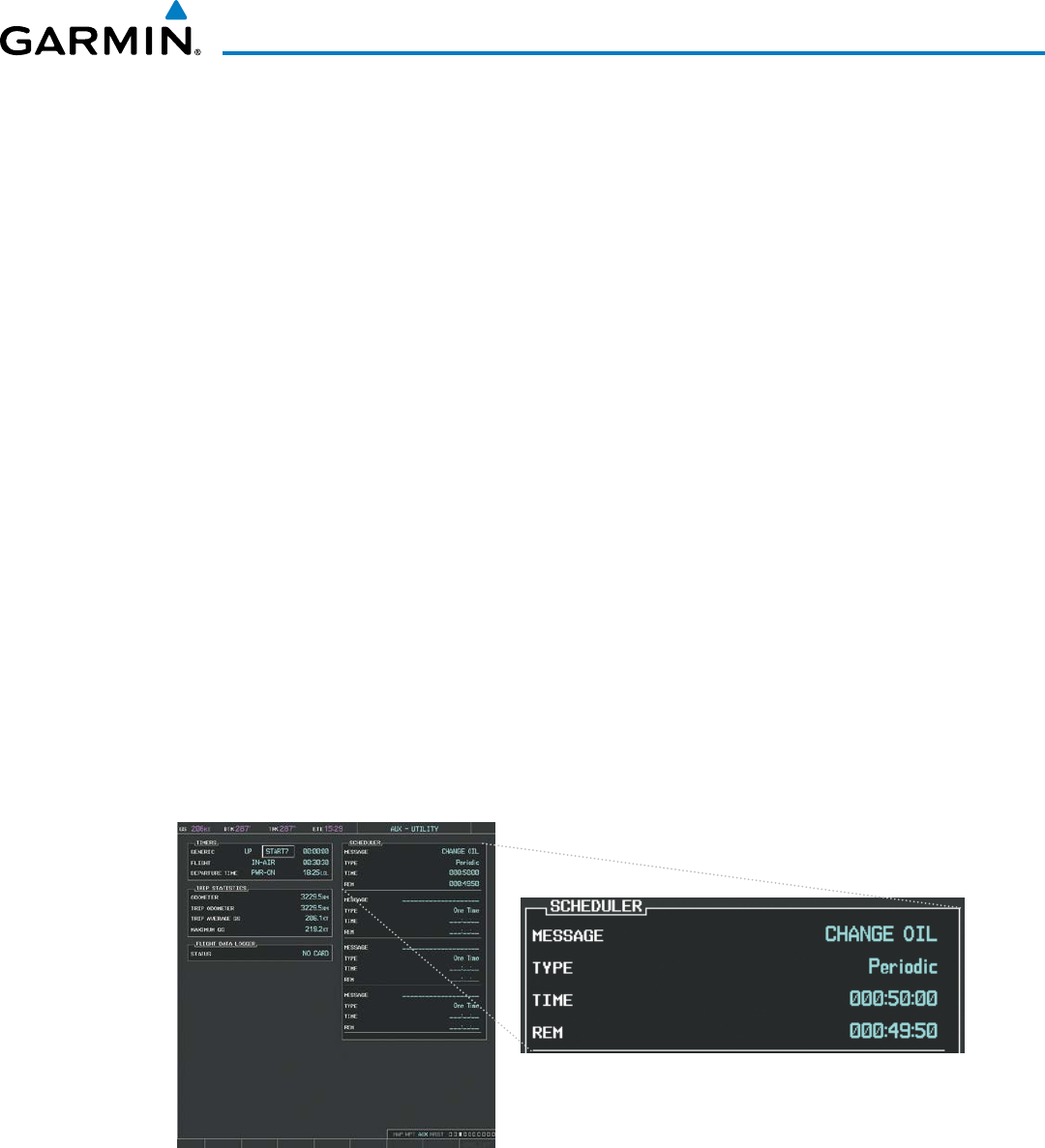
190-00928-04 Rev. A
Garmin G1000 Pilot’s Guide for the Beechcraft 200/B200 Series
51
SYSTEM OVERVIEW
tRiP StatiSticS
The odometer and trip odometer record the total mileage traveled from the last reset; these odometers can
be reset independently. Resetting the trip odometer also resets the average trip groundspeed. Maximum
groundspeed for the period of time since the last reset is also displayed.
Resetting trip statistics readouts
1) Use the FMS Knob to select the AUX - Utility Page.
2) Press the
MENU
Key. The following reset options for trip statistics are displayed:
• Reset Trip ODOM/AVG GS—Resets trip average ground speed readout and odometer
• Reset Odometer—Resets odometer readout only
• Reset Maximum Speed—Resets maximum speed readout only
• Reset All—Resets flight timer, departure timer, odometers, and groundspeed readouts
3) Use the FMS Knob to highlight the desired reset option and press the
ENT
Key. The selected parameters are reset
to zero and begin to display data from the point of reset.
ScHeDuleR
The G1000’s Scheduler feature can be used to enter and display reminder messages (e.g., “Change oil”,
“Switch fuel tanks”, “Overhaul”) in the Alerts Window on the PFD. Messages can be set to display based
on a specific date and time (event), once the message timer reaches zero (one-time; default setting), or
recurrently whenever the message timer reaches zero (periodic). Message timers set to periodic alerting
automatically reset to the original timer value once the message is displayed. When power is cycled,
messages are retained until deleted, and message timer countdown is restarted.
Figure 1-41 Scheduler (Utility Page)
Entering a scheduler message:
1) Select the AUX - Utility Page.
2) Press the FMS Knob momentarily to activate the flashing cursor.
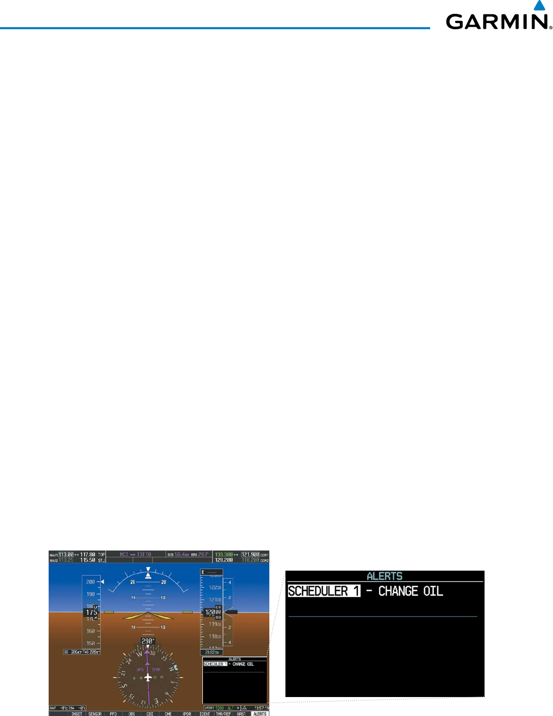
190-00928-04 Rev. A
Garmin G1000 Pilot’s Guide for the Beechcraft 200/B200 Series
52
SYSTEM OVERVIEW
3) Turn the large FMS Knob to highlight the first empty scheduler message naming field.
4) Use the FMS Knob to enter the message text to be displayed in the Alerts Window and press the
ENT
Key.
5) Press the ENT Key again or use the large FMS Knob to move the cursor to the field next to ‘Type’.
6) Turn the small FMS Knob to select set the message alert type:
• Event—Message issued at the specified date/time
• One-time—Message issued when the message timer reaches zero (default setting)
• Periodic—Message issued each time the message timer reaches zero
7) Press the ENT Key again or use the large FMS Knob to move the cursor to the next field.
8) For periodic and one-time message, use the FMS Knob to enter the timer value (HHH:MM:SS) from which to
countdown and press the ENT Key.
9) For event-based messages:
a) Use the FMS Knob to enter the desired date (DD-MMM-YYY) and press the ENT Key.
b) Press the ENT Key again or use the large FMS Knob to move the cursor to the next field.
c) Use the FMS Knob to enter the desired time (HH:MM) and press the ENT Key.
10) Press the ENT Key again or use the large FMS Knob to move the cursor to enter the next message.
Deleting a scheduler message:
1) Select the AUX - Utility Page.
2) Press the FMS Knob momentarily to activate the flashing cursor.
3) Turn the large FMS Knob to highlight the name field of the scheduler message to be deleted.
4) Press the CLR Key to clear the message text. If the CLR Key is pressed again, the message is restored.
5) Press the ENT Key to confirm message deletion.
Scheduler messages appear in the Alerts Window on the PFD and cause the ALERTS Softkey label to
change to ‘ADVISORY’. Pressing the ADVISORY Softkey opens the Alerts Window and acknowledges
the scheduler message. The softkey reverts to the ‘ALERTS’ label and when pressed, the Alerts Window is
removed from the display and the scheduler message is deleted from the message queue.
Figure 1-42 PFD Alerts Window
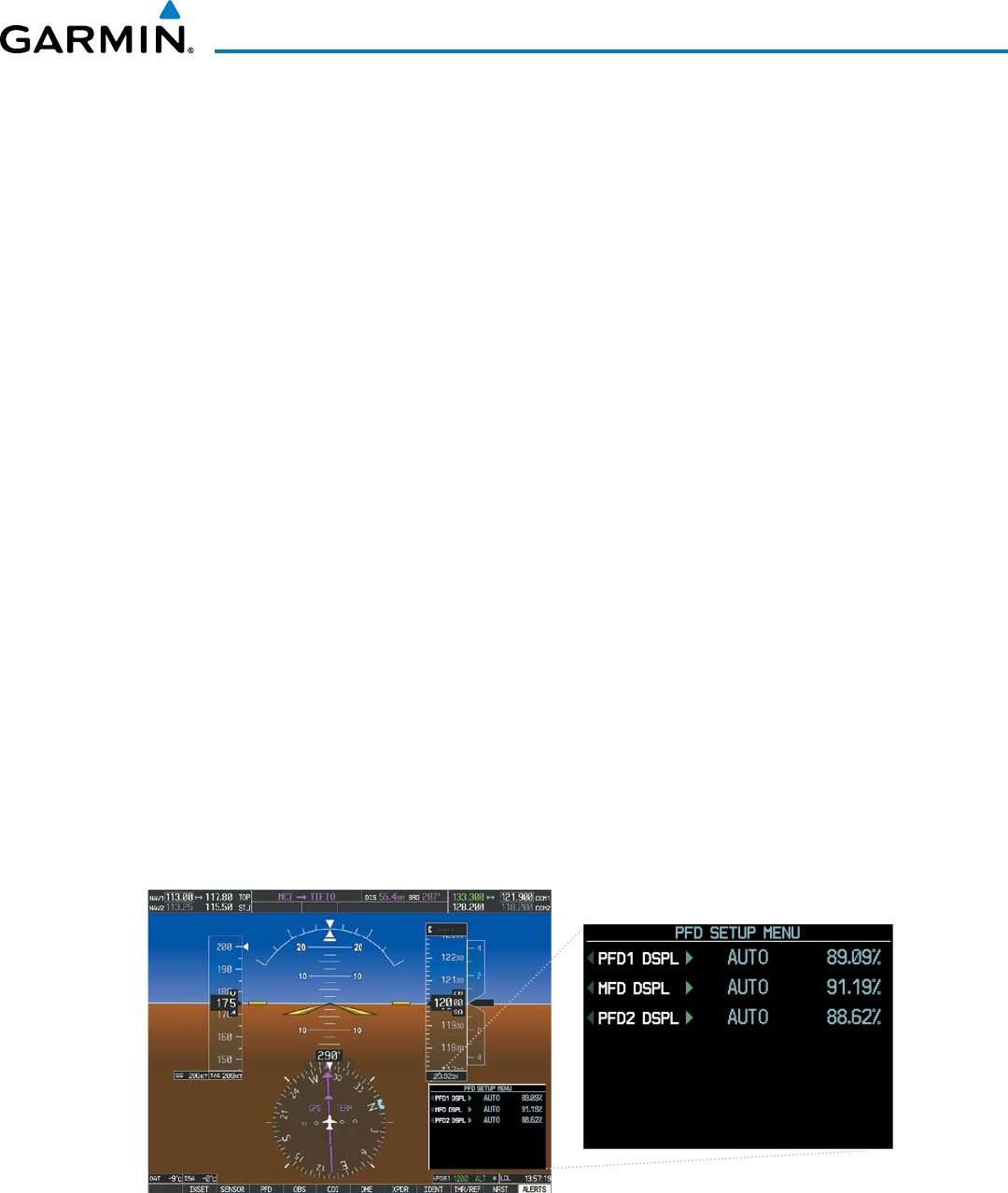
190-00928-04 Rev. A
Garmin G1000 Pilot’s Guide for the Beechcraft 200/B200 Series
53
SYSTEM OVERVIEW
1.8 DISPLAY BACKLIGHTING
The PFD and MFD display backlighting, the PFD and MFD bezel, and the Audio Panel keys can be adjusted
manually in one of two ways:
• Using the individual dimmer bus control for the desired display, or
• Using the PFD Setup Menu and the following procedures. In normal operating mode, backlighting can only be
adjusted from the PFDs. In reversionary mode, adjustments can be made from any remaining displays.
Adjusting display backlighting:
1) Press either PFD
MENU
Key to display the PFD Setup Menu. ‘AUTO’ is now highlighted next to ‘PFD1 DSPL’. If
desired, turn the large FMS Knob to select ‘AUTO’ next to ‘MFD DSPL’ or ‘PFD2 DSPL’.
2) Turn the
small FMS
Knob to select ‘MANUAL’ and press the
ENT
Key. The intensity value is now highlighted.
3) Use the FMS Knob to enter the desired backlighting then press the
ENT
Key.
4) To remove the menu, press the
CLR
or
MENU
Key.
Adjusting key backlighting:
1) Press either PFD
MENU
Key to display the PFD Setup Menu. ‘AUTO’ is now highlighted next to ‘PFD1 DSPL’.
2) Turn the
large FMS
Knob to highlight ‘PFD DSPL’, ‘MFD DSPL’, or ‘PFD2 DSPL’, as desired.
3) Turn the
small FMS
Knob in the direction of the green arrowhead to display ‘PFD1 KEY’, ‘MFD KEY’, or ‘PFD2
KEY’.
4) Turn the
large FMS
Knob to highlight ‘AUTO’.
5) Turn the
small FMS
Knob to select ‘MANUAL’ and press the
ENT
Key. The intensity value is now highlighted.
6) Use the FMS Knob to enter the desired backlighting and press the
ENT
Key.
7) To remove the menu, press the
CLR
or
MENU
Key.
Figure 1-43 PFD Setup Menu

190-00928-04 Rev. A
Garmin G1000 Pilot’s Guide for the Beechcraft 200/B200 Series
54
SYSTEM OVERVIEW
Blank Page
190-00928-04 Rev. A
Garmin G1000 Pilot’s Guide for the Beechcraft 200/B200 Series
55
FLIGHT INSTRUMENTS
SECTION 2 FLIGHT INSTRUMENTS
WARNING: In the event that the airspeed, attitude, altitude, or heading indications become unusable, refer
to the backup instruments.
NOTE: The Automatic Flight Control System (AFCS) provides additional readouts and bugs on selected flight
instruments. Refer to the AFCS Section for details on these bugs and readouts, as they appear on the display
during certain AFCS modes.
Increased situational awareness is provided by replacing the traditional instruments on the panel with easy-
to-scan pilot and copilot Primary Flight Displays (PFD) that features a large horizon, airspeed, attitude, altitude,
vertical speed, and course deviation information. In addition to the flight instruments, navigation, communication,
terrain, traffic, and weather information are also presented on the PFD and explained in other sections of this
Pilot’s Guide.
The following flight instruments and supplemental flight data are displayed on the PFDs:
• Airspeed Indicator, showing
– True Airspeed
– Ground Speed
– Mach number
– Airspeed awareness ranges
– Reference flags
• Attitude Indicator with slip/skid indication
• Altimeter, showing
– Barometric setting
– Selected Altitude
• Vertical Deviation, Glideslope, and
Glidepath Indicators
• Vertical Speed Indicator (VSI)
• Horizontal Situation Indicator, showing
– Turn Rate Indicator
– Bearing pointers and information windows
– DME Information Window (optional)
– Course Deviation Indicator (CDI)
• DME Tuning Window
• Outside Air Temperature (OAT)
• International Standard Atmosphere (ISA)
temperature deviation
• System time
• Wind data
• Vertical Navigation indications
• Radar altimeter (optional)
The PFDs also display various alerts and annunciations.
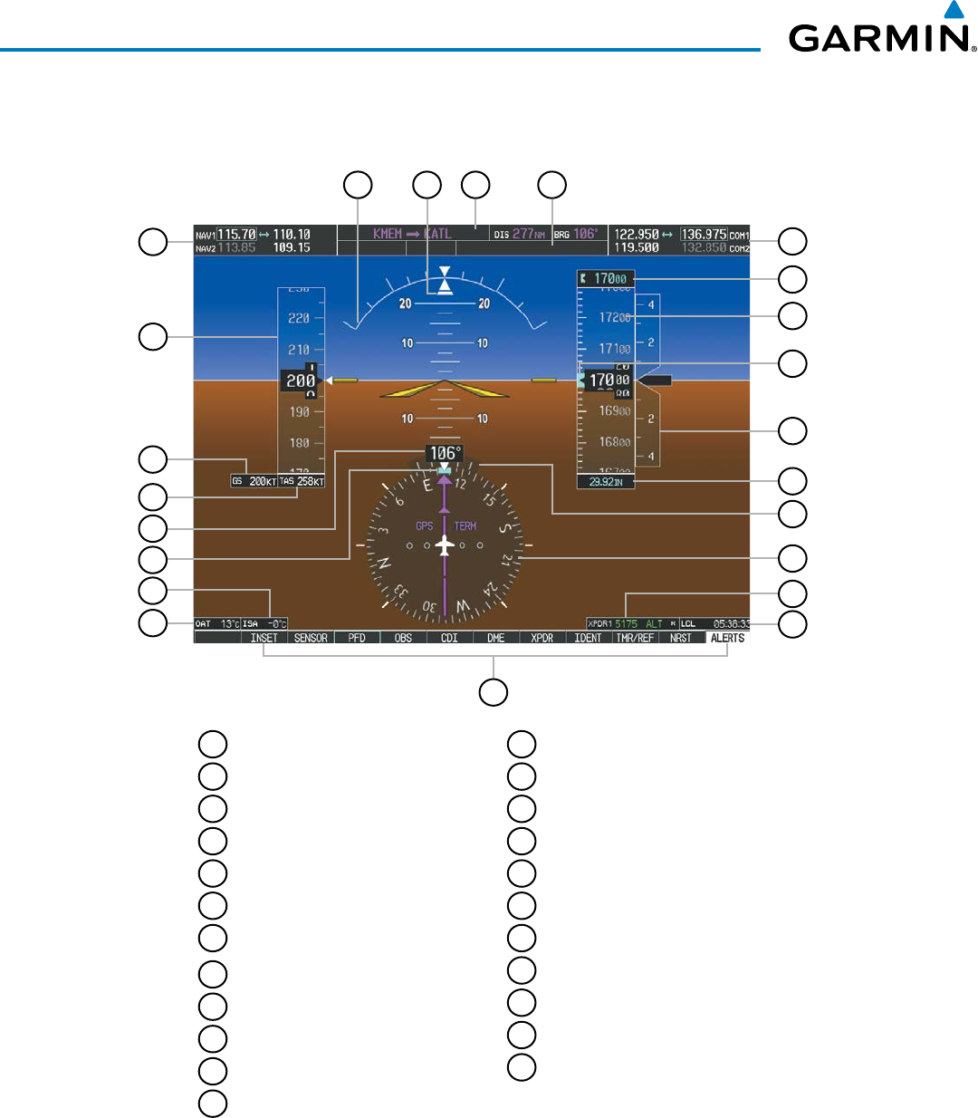
Garmin G1000 Pilot’s Guide for the Beechcraft 200/B200 Series
190-00928-04 Rev. A56
FLIGHT INSTRUMENTS
1
NAV Frequency Box
2
Airspeed Indicator
3
Ground Speed
4
True Airspeed
5
Current Heading
6
Selected Heading Bug
7
International Standard Atmosphere
(ISA) temperature deviation
8
Outside Air Temperature (OAT)
9
Softkeys
10
System Time
11
Transponder Data Box
12
Horizontal Situation Indicator ( HSI)
13
Turn Rate Indicator
14
Altimeter Barometric Setting
15
Vertical Speed Indicator (VSI)
16
Selected Altitude Bug
17
Altimeter
18
Selected Altitude
19
COM Frequency Box
20
AFCS Status Box
21
Navigation Status Box
22
Slip/Skid Indicator
22
Attitude Indicator
Figure 2-1 Primary Flight Display (Default)
10
9
18
15
13
119
22
5
6
2
4
3
17
12
16
20
14
8
11
2123
7
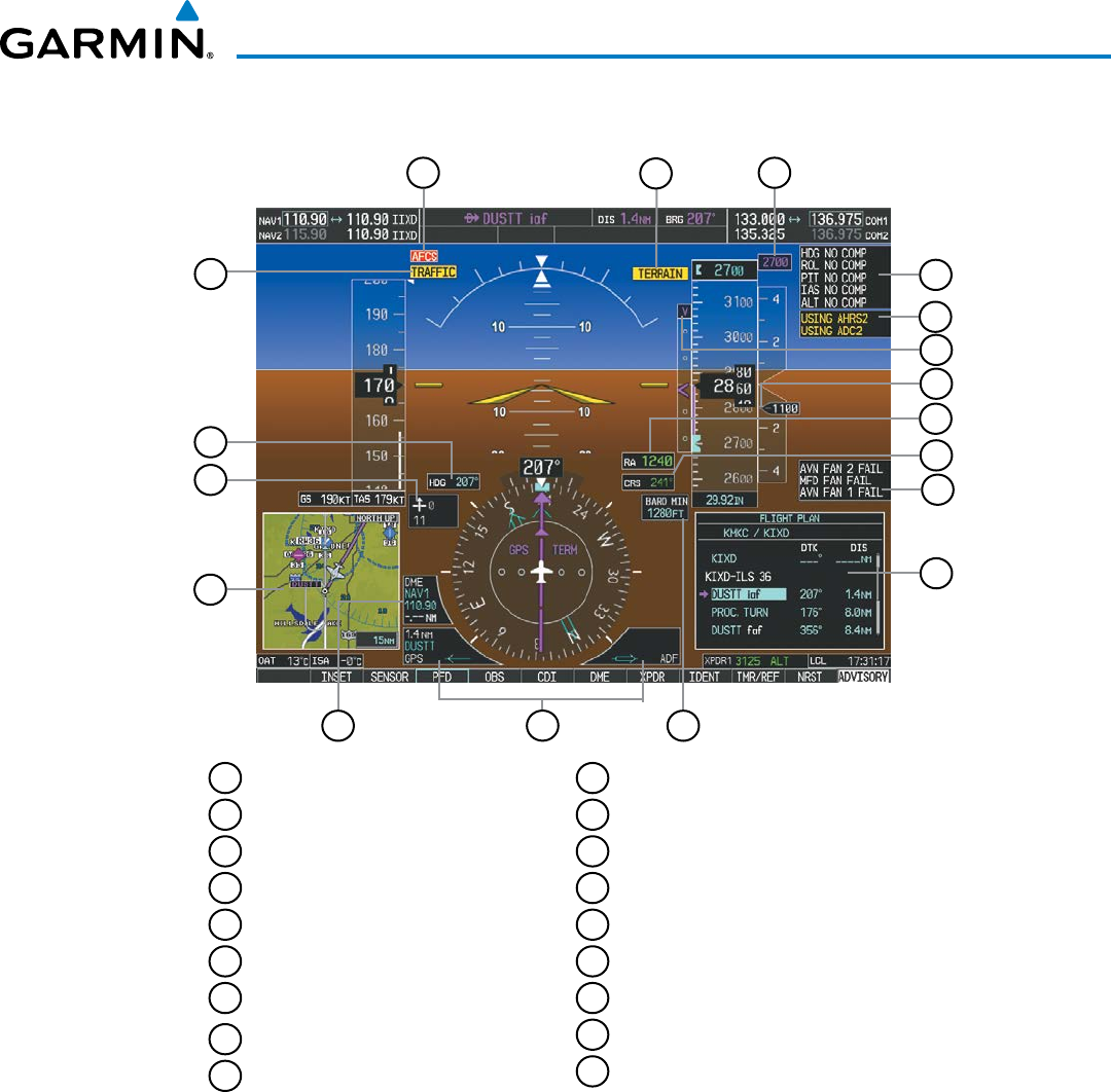
190-00928-04 Rev. A
Garmin G1000 Pilot’s Guide for the Beechcraft 200/B200 Series
57
FLIGHT INSTRUMENTS
2
3
4
6
1
8
7
13
14
18
10
16
12
5
17
15
1
Traffic Annunciation
2
Selected Heading
3
Wind Data
4
Inset Map
5
DME Information Window (optional)
6
Bearing Information Windows
7
Minimum Descent Altitude/
Decision Height
8
Flight Plan Window
9
Annunciation Window
10
Selected Course
11
Radar Altimeter (optional)
12
Current Vertical Speed
13
Vertical Deviation Indicator (VDI)
14
Reversionary Sensor Window
15
Comparator Window
16
Current VNV Target Altitude
17
Terrain Annunciation
18
AFCS Status Annunciation
11
9
Figure 2-2 Additional PFD Information
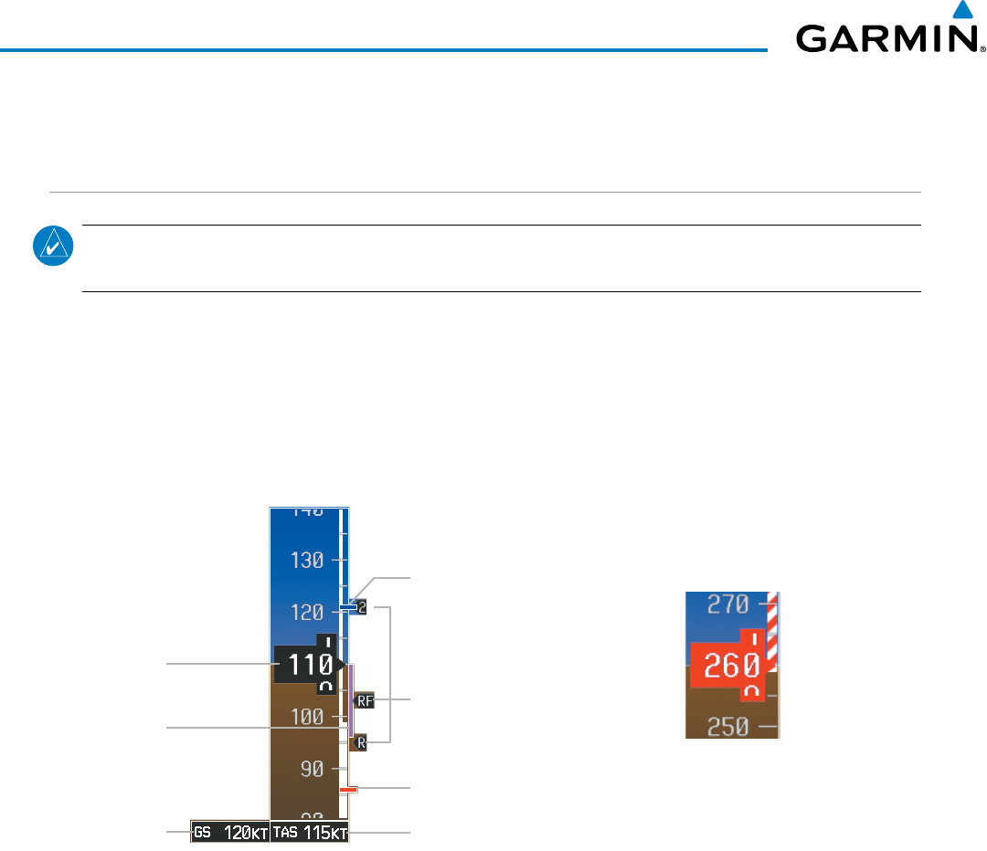
Garmin G1000 Pilot’s Guide for the Beechcraft 200/B200 Series
190-00928-04 Rev. A58
FLIGHT INSTRUMENTS
2.1 FLIGHT INSTRUMENTS
AIRSPEED INDICATOR
NOTE: Refer to the Pilot’s Operating Handbook (POH) and FAA Approved Airplane Flight Manual (AFM) for
speed criteria and Vspeed values.
The Airspeed Indicator displays airspeed on a moving tape rolling number gauge. The true airspeed (TAS)
is displayed in knots below the Airspeed Indicator. When displayed, the Mach number appears in place of the
TAS. The ground speed is displayed to the left of the TAS. The numeric labels and major tick marks on the
moving tape are shown at intervals of 10 knots, while minor tick marks on the moving tape are indicated at
intervals of 5 knots. Speed indication starts at 20 knots, with 60 knots of airspeed viewable at any time. The
actual airspeed is displayed inside the black pointer. The pointer remains black until reaching the high airspeed
limit, at which point it turns red.
Figure 2-4 Red Pointer
Showing Airspeed Above V
MO
Figure 2-3 Airspeed Indicator
Actual
Airspeed
Airspeed
Trend
Vector
True
Airspeed
Vspeed
References
V
MCA
Red Line
V
YSE
Blue Line
Ground
Speed
Speeds above the maximum operating speed, VMO or MMO depending on aircraft altitude, appear in the high
speed warning range, represented on the airspeed tape by red/white “barber pole” coloration.
A red low speed awareness range extends up to the low speed awareness velocity, VLSA. An aural stall warning
is generated as the aircraft approaches a stall condition.
The Airspeed Trend Vector is a vertical magenta line that appears to the right of the color-coded speed range
strip when airspeed is either accelerating or decelerating. One end of the magenta line is anchored to the
tip of the airspeed pointer while the other end moves continuously up or down corresponding to the rate of
acceleration or deceleration. For any constant rate of acceleration or deceleration, the moving end of the line
shows approximately what the indicated airspeed value will be in six seconds. If the trend vector crosses VMO/
MMO, the text of the actual airspeed readout changes to yellow while the pointer remains black. The trend
vector is absent if the speed remains constant or if any data needed to calculate airspeed is not available due to
a system failure.
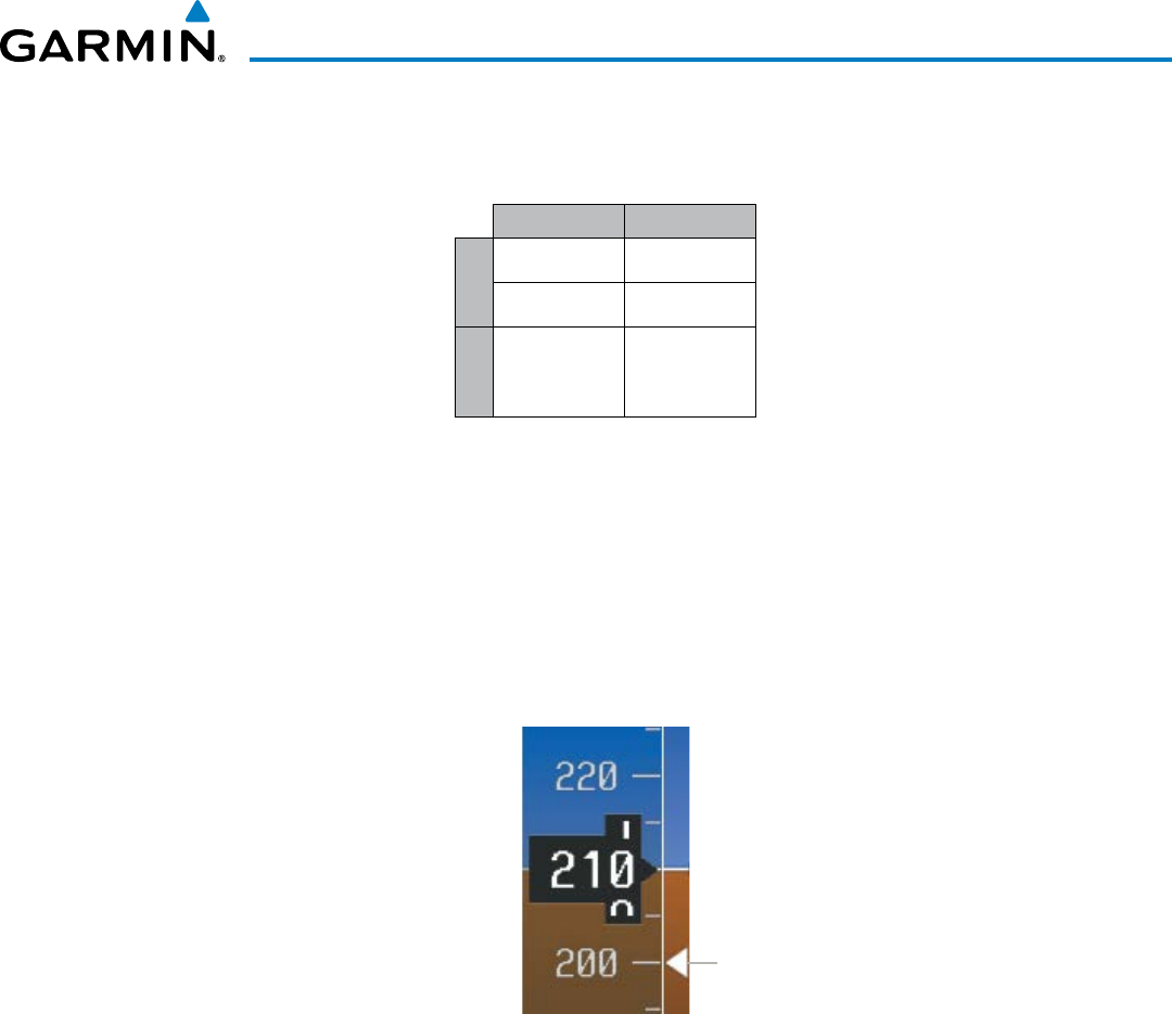
190-00928-04 Rev. A
Garmin G1000 Pilot’s Guide for the Beechcraft 200/B200 Series
59
FLIGHT INSTRUMENTS
Vspeeds can be changed and their flags turned on/off from the Timer/References Window. When active (on),
the Vspeeds are displayed at their respective locations to the right of the airspeed scale.
Vspeed Flag
Takeoff
V
R
R
V
2
2
Landing
V
REF
RF
Table 2-1 Vspeed Flag Labels
Vspeeds are categorized as either takeoff or landing. Takeoff Vspeed flags are automatically turned off when
airspeed reaches 160 knots. The order in which the categories are displayed is determined by whether the
aircraft is on the ground or in the air. If the aircraft is on the ground, the takeoff Vspeeds are displayed at the
top of the Vspeed list. If the aircraft is in the air, the landing Vspeeds are displayed at the top.
The maximum speed with approach flaps is displayed as a solid white triangle to the right of the airspeed
scale. This indication is always displayed and cannot be turned off by the pilot.
Figure 2-5 Maximum Flaps Extended Speed Reference
Maximum
Approach
Flaps Speed
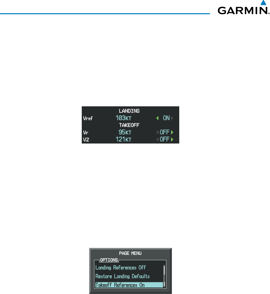
Garmin G1000 Pilot’s Guide for the Beechcraft 200/B200 Series
190-00928-04 Rev. A60
FLIGHT INSTRUMENTS
Changing Vspeeds and turning Vspeed flags on/off:
1) Press the
TMR/REF
Softkey.
2) Turn the
large FMS
Knob to highlight the desired Vspeed.
3) Use the small FMS Knob to change the Vspeed in 1-kt increments (when a speed has been changed from a
default value, an asterisk appears next to the speed).
4) Press the
ENT
Key or turn the large FMS Knob to highlight the ON/OFF field
5) Turn the
small FMS
Knob clockwise to ON or counterclockwise to OFF.
6) To remove the window, press the
CLR
Key or the
TMR/REF
Softkey.
Figure 2-6 Takeoff and Landing Vspeeds
(Timer/References Window)
Vspeed flags can be turned on or off and values restored all at once or by category (takeoff and landing).
Modifying Vspeeds (on, off, restore defaults):
1) Press the
TMR/REF
Softkey.
2) Press the
MENU
Key.
3) Turn the FMS Knob to highlight the desired selection.
4) Press the
ENT
Key.
5) To remove the window, press the CLR Key or the TMR/REF Softkey.
Figure 2-7 Page Menu
(Timer/References Window)
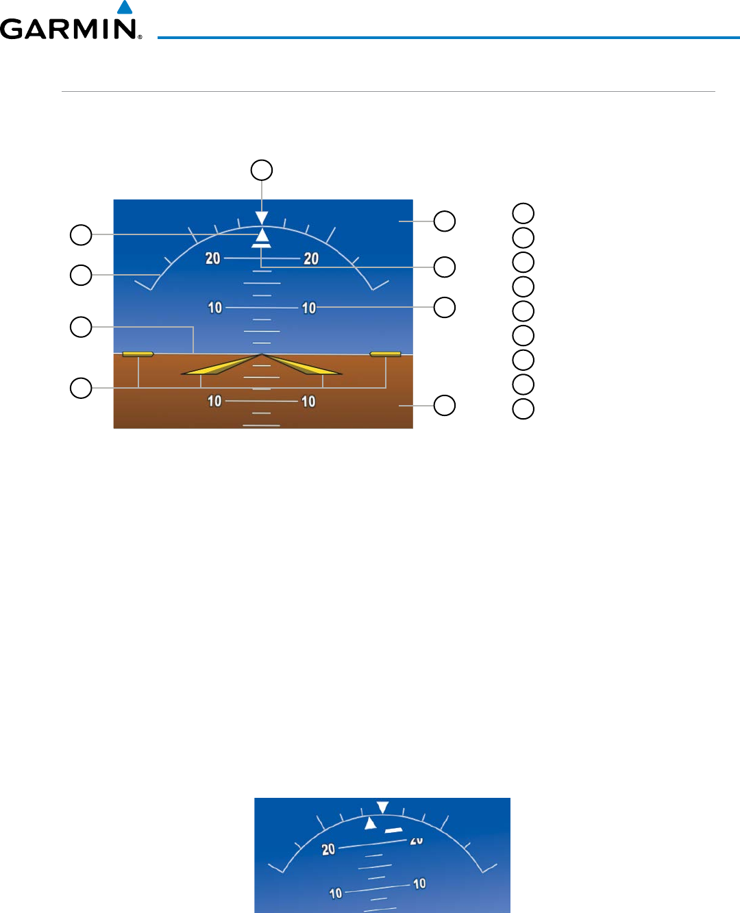
190-00928-04 Rev. A
Garmin G1000 Pilot’s Guide for the Beechcraft 200/B200 Series
61
FLIGHT INSTRUMENTS
ATTITUDE INDICATOR
Attitude information is displayed over a virtual blue sky and brown ground with a white horizon line. The
Attitude Indicator displays the pitch, roll, and slip/skid information.
1
Roll Pointer
2
Roll Scale
3
Horizon Line
4
Aircraft Symbol
5
Land Representation
6
Pitch Scale
7
Slip/Skid Indicator
8
Sky Representation
9
Roll Scale Zero
Figure 2-8 Attitude Indicator
5
6
8
7
2
4
3
9
1
The horizon line is part of the pitch scale. Above and below the horizon line, major pitch marks and numeric
labels are shown for every 10˚, up to 80˚. Minor pitch marks are shown for intervening 5˚ increments, up to
25˚ below and 45˚ above the horizon line. Between 20˚ below to 20˚ above the horizon line, minor pitch marks
occur every 2.5˚. When the Synthetic Vision System (SVS) is activated, the pitch scale is reduced to 10˚ up and
7.5˚ down; refer to the Additional Features section for more information about SVS.
The inverted white triangle indicates zero on the roll scale. Major tick marks at 30˚ and 60˚ and minor tick
marks at 10˚, 20˚, and 45˚ are shown to the left and right of the zero. Angle of bank is indicated by the position
of the pointer on the roll scale.
The Slip/Skid Indicator is the bar beneath the roll pointer. The indicator bar moves with the roll pointer and
moves laterally away from the pointer to indicate uncoordinated flight. Slip (inside the turn) or skid (outside
the turn) is indicated by the location of the bar relative to the pointer.
When the optional Garmin Electronic Stability and Protection (Garmin ESP™) system is available, additional
indications may appear on the pitch and roll scales; refer to the Additional Features and AFCS Sections for more
information about ESP.
Figure 2-9 Slip/Skid Indication
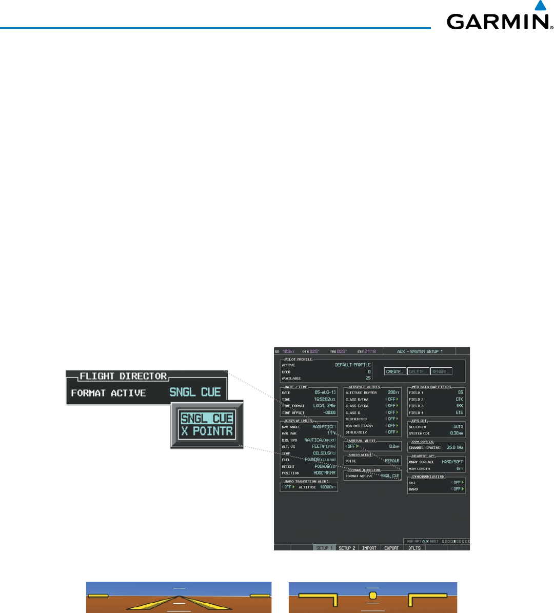
Garmin G1000 Pilot’s Guide for the Beechcraft 200/B200 Series
190-00928-04 Rev. A62
FLIGHT INSTRUMENTS
The yellow symbolic aircraft on the Attitude Indicator changes appearance based on selection of AFCS
flight director Command Bar format (see the AFCS Section for details). Both PFDs show the same Command
Bar format and Aircraft Symbol. The Command Bar format (single-cue or cross-pointer) may be selected from
the AUX - System Setup 1 Page (Figure 2-10). If a compatible lift computer is installed, the cross-pointer
option will be unavailable.
Changing Command Bar format:
1) Turn the large FMS Knob to select the AUX page group on the MFD.
2) Turn the small FMS Knob to select the System Setup Page.
3) If necessary, press the SETUP 1 Softkey to display the System Setup 1 Page.
4) Press the FMS Knob to activate the cursor.
5) Turn the large FMS Knob to highlight ‘Format Active’ in the ‘Flight Director’ box.
6) Turn the small FMS Knob to highlight the desired format.
’SNGL CUE’ to display Command Bars as a single cue (Figure 2-10).
Or:
’X-POINTER’ to display Command Bars as a cross-pointer (Figure 2-10).
Figure 2-10 Flight Director Format
(AUX - System Setup 1 Page)
Single-cue Cross-pointer
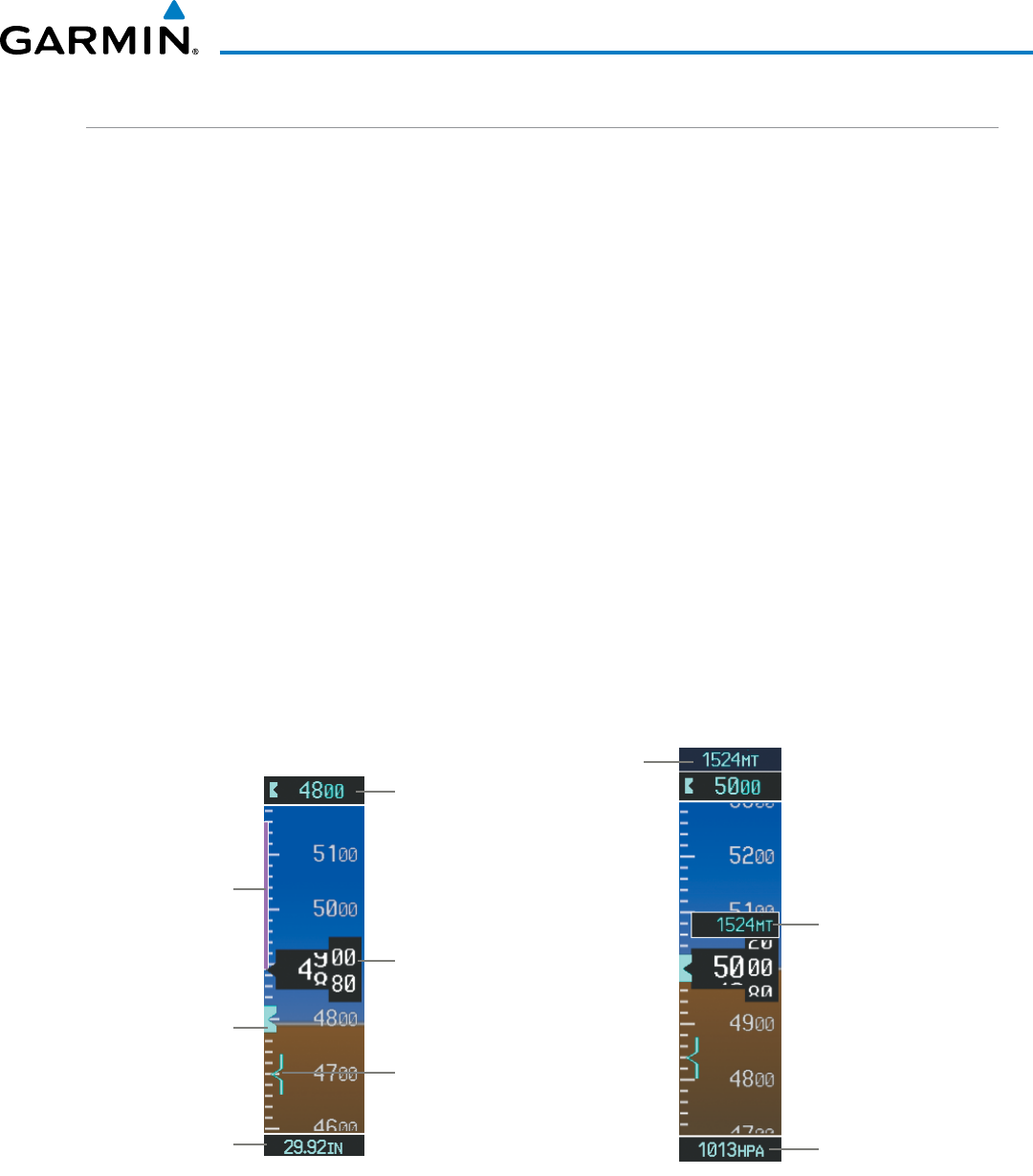
190-00928-04 Rev. A
Garmin G1000 Pilot’s Guide for the Beechcraft 200/B200 Series
63
FLIGHT INSTRUMENTS
ALTIMETER
The Altimeter displays 600 feet of barometric altitude values at a time on a moving tape rolling number gauge.
Numeric labels and major tick marks are shown at intervals of 100 feet. Minor tick marks are at intervals of 20
feet. The indicated altitude is displayed inside the black pointer.
The Selected Altitude is displayed above the Altimeter in the box indicated by a selection bug symbol. A bug
corresponding to this altitude is shown on the tape. If the Selected Altitude exceeds the range shown on the
tape, the bug appears at the upper or lower edge of the tape. When the metric value is selected it is displayed
in a separate box above the Selected and Indicated Altitudes (Figure 2-11). See the AFCS Section for more
information about Selected Altitude.
The Altitude Trend Vector is a vertical magenta line that appears to the left of the altitude range strip when
the aircraft is either climbing or descending. One end of the magenta line is anchored to the tip of the altitude
pointer while the other end moves continuously up or down according to the rate of vertical speed. For any
constant rate of vertical speed, the moving end of the line shows approximately what the indicated altitude
value will be in six seconds. The trend vector is absent if the altitude remains constant or if data needed for
calculation is not available due to a system failure.
Setting the Selected Altitude:
Turn the
ALT SEL
Knob to set the Selected Altitude in 100-ft increments.
If set, the Minimum Descent Altitude/Decision Height (MDA/DH) value is also available for the Selected Altitude.
When the altimeter is configured for metric units, the selected altitude is adjusted in 50 meter increments.
Figure 2-11 Altimeter
MDA/DH
Altitude
Bug
Barometric
Setting
Altitude
Trend
Vector
Selected
Altitude
Bug
Selected
Altitude
Indicated
Altitude
Barometric
Setting Box
(Hectopascals)
Indicated
Altitude
(Meters)
Selected
Altitude
(Meters)

Garmin G1000 Pilot’s Guide for the Beechcraft 200/B200 Series
190-00928-04 Rev. A64
FLIGHT INSTRUMENTS
Displaying altitude in meters:
1) Press the PFD Softkey to display the second-level softkeys.
2) Press the ALT UNIT Softkey.
3) Press the METERS Softkey to turn on metric altitude readouts.
4) Press the
BACK
Softkey to return to the top-level softkeys.
The barometric pressure setting is displayed below the Altimeter in inches of mercury (in Hg) or hectopascals
(hPa). Adjusting the altimeter barometric setting creates discontinuities in VNAV vertical deviation, moving
the descent path. For large adjustments, it may take several minutes for the aircraft to re-establish on the
descent path. If the change is made while nearing a waypoint with a VNAV Target Altitude, the aircraft may not
re-establish on the descent path in time to meet the vertical constraint.
Selecting the altimeter barometric pressure setting:
Turn the BARO Knob to select the desired setting.
Selecting standard barometric pressure:
Press the BARO Knob to select standard pressure; STD BARO is displayed in barometric setting box.
Or:
1) Press the PFD Softkey to display the second-level softkeys.
2) Press the STD BARO Softkey; STD BARO is displayed in barometric setting box.
Figure 2-12 Standard Barometric Altimeter Setting
Changing altimeter barometric pressure setting units:
1) Press the PFD Softkey to display the second-level softkeys.
2) Press the ALT UNIT Softkey.
3) Press the IN Softkey to display the barometric pressure setting in inches of mercury (in Hg).
Or, press the HPA Softkey to display the barometric pressure setting in hectopascals (hPa; see Figure 2-12).
4) Press the
BACK
Softkey to return to the top-level softkeys.
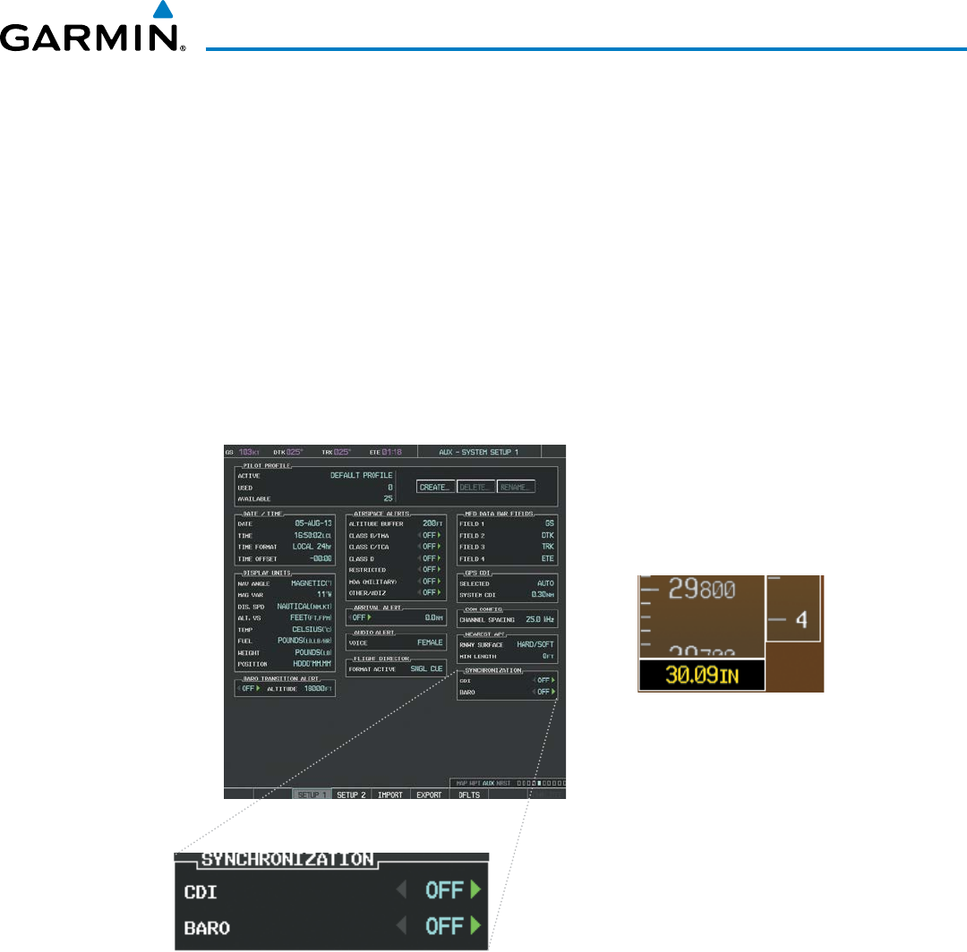
190-00928-04 Rev. A
Garmin G1000 Pilot’s Guide for the Beechcraft 200/B200 Series
65
FLIGHT INSTRUMENTS
If the barometric altimeter settings differ between PFDs, the readouts turn yellow. The settings can be
synchronized from the PFD Setup Menu. Once the settings are synchronized (BARO SYNC turned on), they
remain synchronized until the setting is turned off.
Synchronizing the altimeter barometric pressure settings:
1) Turn the large FMS Knob to select the AUX page group on the MFD.
2) Turn the small FMS Knob to select the System Setup Page.
3) If necessary, press the SETUP 1 Softkey to display the System Setup 1 Page.
4) Press the
FMS
Knob to activate the cursor.
5) Turn the
large FMS
Knob to highlight ‘BARO’ in the Synchronization box.
6) Turn the
small FMS
Knob clockwise to ON or counterclockwise to OFF.
Figure 2-13 System Setup Page, Barometric Pressure Synchronization
Barometric Settings
not Synchronized on PFD
Displayed in Yellow

Garmin G1000 Pilot’s Guide for the Beechcraft 200/B200 Series
190-00928-04 Rev. A66
FLIGHT INSTRUMENTS
VERTICAL SPEED INDICATOR (VSI)
The Vertical Speed Indicator (VSI) displays the aircraft vertical speed using a non-moving tape labeled at 2000
and 4000 fpm with minor tick marks every 1000 fpm. The current vertical speed is displayed in the pointer
along the tape. Digits appear in the pointer when the climb or descent rate is greater than 100 fpm. If the rate
of ascent/descent exceeds 4000 fpm, the pointer appears at the corresponding edge of the tape and the rate
appears inside the pointer.
A magenta chevron bug is displayed as the Required Vertical Speed Indication (RVSI) for reaching a VNV
Target Altitude once the “TOD [Top of Descent] within 1 minute” alert has been generated. See the Flight
Management Section for details on VNV features, and refer to Section 2.2, Supplemental Flight Data, for more
information about VNV indications on the PFD.
VERTICAL DEVIATION
The Vertical Deviation Indicator (VDI; Figure 2-14) uses a magenta chevron to indicate the baro-VNV vertical
deviation when Vertical Navigation (VNV) is being used; the VDI appears in conjunction with the “TOD within
1 minute” alert. Full-scale deflection (two dots) is 1000 feet. The VDI is removed from the display if vertical
deviation becomes invalid. See the Flight Management and AFCS sections for details on VNV features, and refer
to Section 2.2, Supplemental Flight Data, for more information about VNV indications on the PFD.
The Glideslope Indicator (Figure 2-15) appears to the left of the Altimeter whenever an ILS frequency is tuned
in the active NAV field and the aircraft heading and selected course are within 107˚. A green diamond acts as
the Glideslope Indicator, like a glideslope needle on a conventional indicator. If a localizer frequency is tuned
and there is no glideslope, “NO GS” is displayed in place of the diamond.
The glidepath is analogous to the glideslope for RNAV approach service levels supporting SBAS vertical
guidance (LNAV+V, LNAV/VNAV, LPV, LP+V). When one of these RNAV approaches is loaded into the flight
plan, GPS is the selected navigation source, and SBAS is used for vertical approach guidance, the Glidepath
Indicator appears as a magenta diamond (Figure 2-16). If the approach type downgrades past the final approach
fix (FAF), “NO GP” is displayed in place of the diamond.
While executing an LNAV/VNAV approach and SBAS is unavailable, baro-VNAV (barometric vertical
navigation) is used for vertical guidance. This occurs due to any of the following conditions:
• SBAS fails or becomes unavailable prior to the FAF
• The aircraft is outside of SBAS coverage
• SBAS is manually disabled on the GPS Status page
Baro-VNAV is also the source of vertical approach guidance if the LNAV/VNAV procedure does not support
SBAS vertical guidance.
While baro-VNAV is being utilized, the Glidepath Indicator appears as a magenta pentagon (Figure 2-17). If
the approach type downgrades past the final approach fix (FAF), “NO GP” is displayed in place of the pentagon.
While executing an LNAV/VNAV or RNP approach and between the FAF and MAP, excessive deviation
indicators appear as vertical yellow lines (Figure 2-17) to indicate an area where the vertical deviation exceeds
±75 feet.
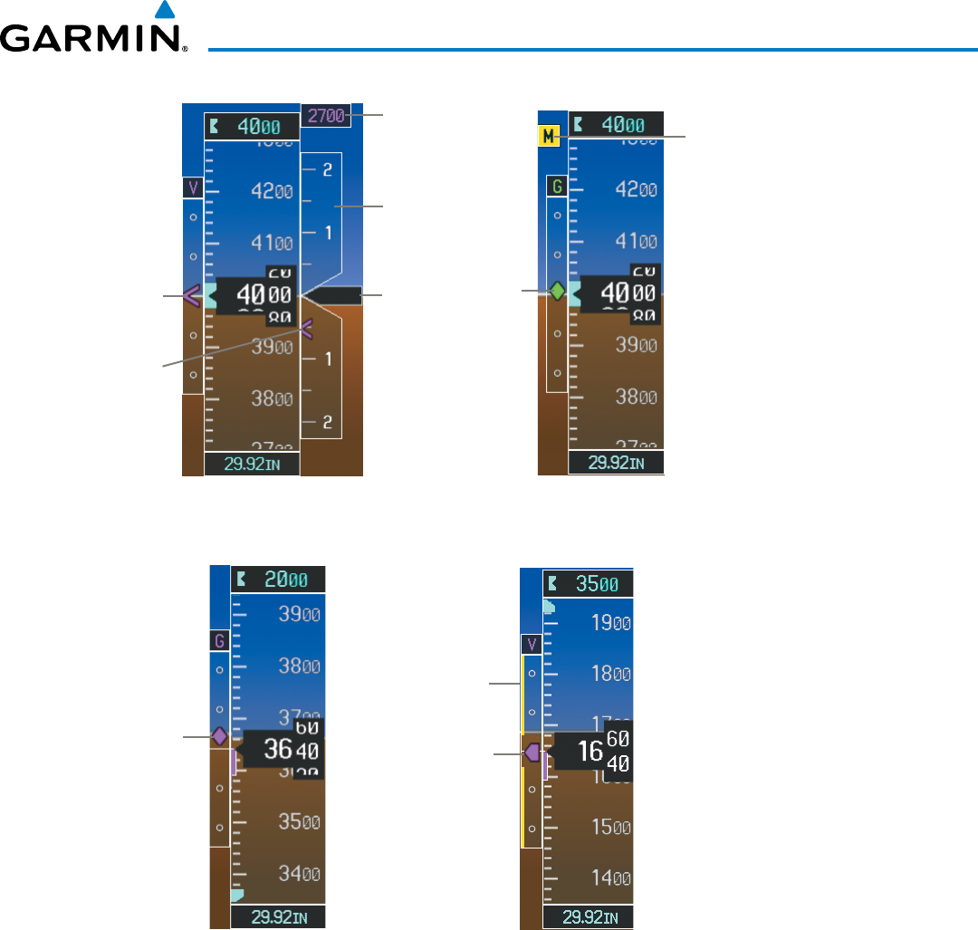
190-00928-04 Rev. A
Garmin G1000 Pilot’s Guide for the Beechcraft 200/B200 Series
67
FLIGHT INSTRUMENTS
Figure 2-14 Vertical Speed and
Deviation Indicator (VSI and VDI)
Vertical
Speed
Indicator
Required
Vertical
Speed
Vertical
Speed
Pointer
VNV Target
Altitude
Vertical
Deviation
Indicator
Glideslope
Indicator
Marker
Beacon
Annunciation
Figure 2-15 Glideslope Indicator
Glipepath
Indicator
Figure 2-16 Glidepath Indicator
Glipepath
Indicator
Figure 2-17 Glidepath Indicator
Excessive
Deviation
Indicator
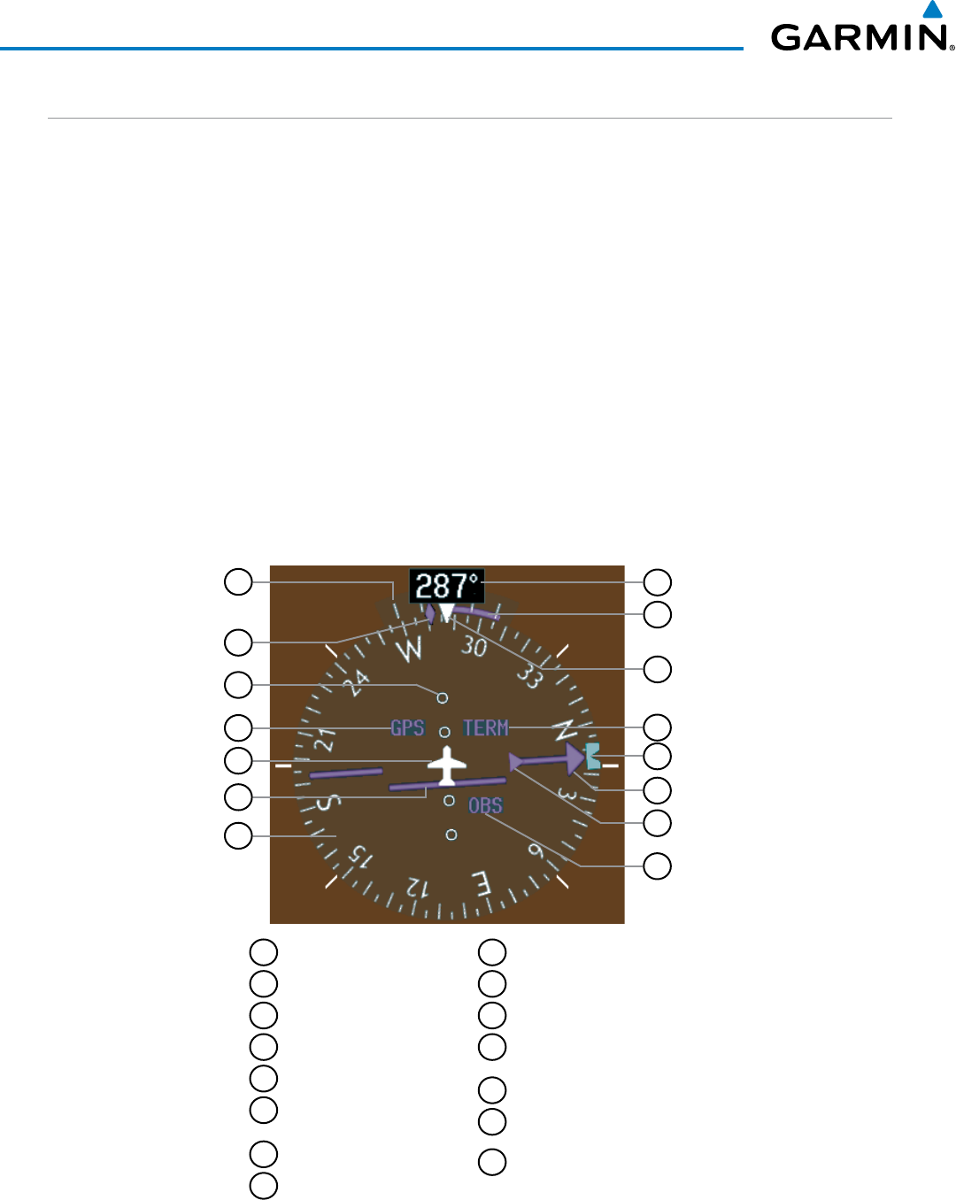
Garmin G1000 Pilot’s Guide for the Beechcraft 200/B200 Series
190-00928-04 Rev. A68
FLIGHT INSTRUMENTS
HORIZONTAL SITUATION INDICATOR (HSI)
The Horizontal Situation Indicator (HSI) displays a rotating compass card in a heading-up orientation. Letters
indicate the cardinal points and numeric labels occur every 30˚. Major tick marks are at 10˚ intervals and minor
tick marks at 5˚ intervals. A digital reading of the current heading appears on top of the HSI, and the current
track is represented on the HSI by a magenta diamond indicator. The HSI also presents turn rate, course
deviation, bearing, and navigation source information and is available in two formats (360˚ compass rose and
140˚ arc).
Changing the HSI display format:
1) Press the
PFD
Softkey.
2) Press the HSI FRMT Softkey.
3) Press the
360 HSI
or
ARC HSI
Softkey.
The 360˚ HSI contains a Course Deviation Indicator (CDI), with a Course Pointer, To/From Indicator, and a
sliding deviation bar and scale. The course pointer is a single line arrow (GPS, VOR1, and LOC1) or a double
line arrow (VOR2 and LOC2) which points in the direction of the set course. The To/From arrow rotates with
the course pointer and is displayed when the active NAVAID is received.
11
7
6
5
3
2
1
12
10
4
14
15
13
Figure 2-18 Horizontal Situation Indicator (HSI)
8
9
1
Turn Rate Indicator
2
Current Track Indicator
3
Lateral Deviation Scale
4
Navigation Source
5
Aircraft Symbol
6
Course Deviation Indicator
(CDI)
7
Rotating Compass Rose
8
OBS Mode Active
9
To/From Indicator
10
Course Pointer
11
Heading Bug
12
Flight Phase/Approach
Service Level
13
Lubber Line
14
Turn Rate/Heading
Trend Vector
15
Current Heading
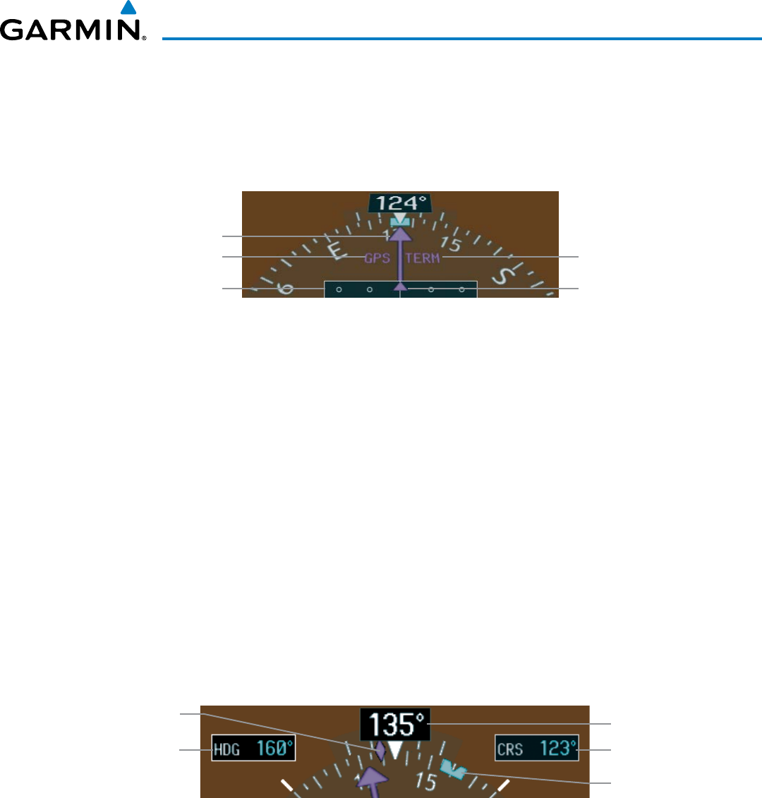
190-00928-04 Rev. A
Garmin G1000 Pilot’s Guide for the Beechcraft 200/B200 Series
69
FLIGHT INSTRUMENTS
The Arc HSI is a 140˚ expanded section of the compass rose. The Arc HSI contains a Course Pointer,
To/From Indicator, a sliding deviation indicator (the To/From and deviation indicators are combined), and a
deviation scale. Upon station passage, the To/From Indicator flips and points to the tail of the aircraft, just like
a conventional To/From flag. Depending on the navigation source, the CDI on the Arc HSI can appear in two
different ways: an arrowhead (GPS, VOR, OBS) or a diamond (LOC).
Figure 2-19 Arc HSI
Lateral Deviation Scale Course Deviation and
To/From Indicator
Course Pointer
Navigation Source Flight Phase Annunciation
The Selected Heading is shown to the upper left of the HSI for 3 seconds after being adjusted The light blue
bug on the compass rose corresponds to the Selected Heading. While the HSI is displayed as an arc, if the
Selected Heading Bug is adjusted off the shown portion of the compass rose, the digital reading is displayed.
Adjusting the Selected Heading:
Turn the
HDG
Knob to set the Selected Heading.
Press the HDG Knob to synchronize the bug to the current heading.
The Selected Course is shown to the upper right of the HSI for 3 seconds after being adjusted. While the
HSI is displayed as an arc, the Selected Course is displayed whenever the Course Pointer is not within the 140˚
currently shown.
Adjusting the Selected Course:
Turn the
CRS
Knob to set the Selected Course.
Press the CRS Knob to re-center the CDI and return the course pointer to the bearing of the active waypoint or
navigation station (see OBS Mode for adjusting a GPS course).
Figure 2-20 Heading and Course Indications
Selected Heading Selected Course
Current Heading
Current Track Indicator
Selected Heading Bug
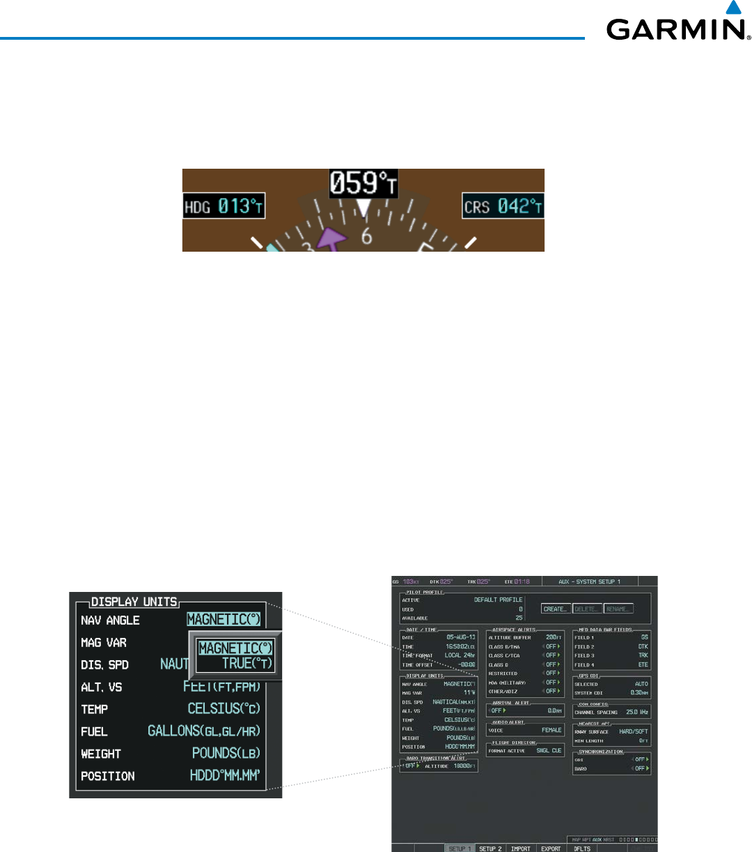
Garmin G1000 Pilot’s Guide for the Beechcraft 200/B200 Series
190-00928-04 Rev. A70
FLIGHT INSTRUMENTS
Navigation angles (track, heading, course, bearing) are corrected to the computed magnetic variation (‘Mag
Var’) or referenced to true north (denoted ‘T’), set on the AUX - System Setup 1 Page. When an approach
referenced to true north has been loaded into the flight plan, the system generates a message to change the
navigation angle setting to ‘True’ at the appropriate time.
Figure 2-21 Heading and Course Indications (True)
Changing the navigation angle setting:
1) Turn the large FMS Knob to select the AUX page group on the MFD.
2) Turn the small FMS Knob to select the System Setup Page.
3) If necessary, press the SETUP 1 Softkey to display the System Setup 1 Page.
4) Press the FMS Knob to activate the cursor.
5) Turn the
large FMS
Knob to highlight ‘Nav Angle’ in the ‘Display Units’ box (Figure 2-22).
6) Turn the small FMS Knob to highlight the desired setting and press the ENT Key.
• TRUE - References angles to true north (denoted with ‘T’)
• MAGNETIC - Angles corrected to the computed magnetic variation (‘Mag Var’)
Figure 2-22 System Setup Page, Navigation Angle Settings
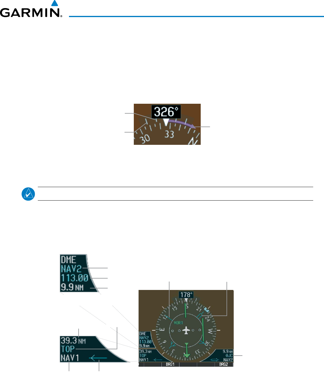
190-00928-04 Rev. A
Garmin G1000 Pilot’s Guide for the Beechcraft 200/B200 Series
71
FLIGHT INSTRUMENTS
TURN RATE INDICATOR
The Turn Rate Indicator is located directly above the rotating compass card. Tick marks to the left and right
of the lubber line denote half-standard and standard turn rates. A magenta Turn Rate Trend Vector shows the
current turn rate. The end of the trend vector gives the heading predicted in 6 seconds, based on the present
turn rate. A standard-rate turn is shown on the indicator by the trend vector stopping at the standard turn
rate tick mark, corresponding to a predicted heading of 18˚ from the current heading. At rates greater than 4
deg/sec, an arrowhead appears at the end of the magenta trend vector and the prediction is no longer valid.
Standard
Turn Rate
Half Standard
Turn Rate Arrow Shown
for Turn Rate
> 4 Degrees
per Second
Figure 2-23 Turn Rate Indicator and Trend Vector
BEARING POINTERS AND INFORMATION WINDOWS
NOTE: When the Arc HSI is displayed, the Bearing Information windows and pointers are disabled.
Two bearing pointers and associated information can be displayed on the HSI for NAV and GPS sources.
The pointers are light blue and are single- (BRG1) or double-lined (BRG2); an icon is shown in the respective
information window to indicate the pointer type. The bearing pointers never override the CDI and are
visually separated from the CDI by a white ring (shown when bearing pointers are selected but not necessarily
visible due to data unavailability).
Figure 2-24 HSI with Bearing and DME Information
Bearing 2 Information Window
Bearing 1 Information Window
Pointer
Icon
Distance to
Bearing Source
Bearing
Source
Bearing 2
Pointer
Bearing 1
Pointer
Frequency
Tuning Mode
Distance
Station
Identifier
DME Information Window
(optional)

Garmin G1000 Pilot’s Guide for the Beechcraft 200/B200 Series
190-00928-04 Rev. A72
FLIGHT INSTRUMENTS
When a bearing pointer is displayed, its associated information window is also displayed. The Bearing
Information windows (Figure 2-24) are displayed to the lower sides of the HSI and show:
• Bearing source (NAV, GPS, ADF)
• Pointer icon (BRG1 = single line, BRG2 = double line)
• Frequency (NAV)
• Station/waypoint identifier (NAV, GPS)
• GPS-derived great circle distance to bearing
source
If the NAV radio is the bearing source and is tuned to an ILS frequency (refer to the Audio Panel and CNS
Section for information on tuning the radios), the bearing pointer is removed from the HSI and the frequency
is replaced with “ILS”. When NAV1 or NAV2 is the selected bearing source, the frequency is replaced by the
station identifier when the station is within range. If GPS is the bearing source, the active waypoint identifier
is displayed in lieu of a frequency.
The bearing pointer is removed from the HSI and “NO DATA” is displayed in the information window if:
• The NAV radio is not receiving the tuned VOR
station
• GPS is the bearing source and an active waypoint
is not selected
Selecting bearing display and changing sources:
1) Press the PFD Softkey.
2) Press a BRG Softkey to display the desired bearing pointer and information window with a NAV source.
3) Press the BRG Softkey again to change the bearing source to GPS.
4) Press the BRG Softkey a third time to change the bearing source to ADF (note: ADF radio installation is
optional).
5) To remove the bearing pointer and information window, press the BRG Softkey again.
DME INFORMATION WINDOW
NOTE: DME radio installation is optional.
The DME Information Window is displayed above the BRG1 Information Window and shows the DME
label, tuning mode (NAV1, NAV2, or HOLD), frequency, and distance. When a signal is invalid, the distance
is replaced by “–.– – NM”. Refer to the Audio Panel and CNS Section for information on tuning the radios.
Displaying the DME Information Window:
1) Press the PFD Softkey.
2) Press the DME Softkey to display the DME Information Window above the BRG1 Information Window.
3) To remove the DME Information Window, press the DME Softkey again.
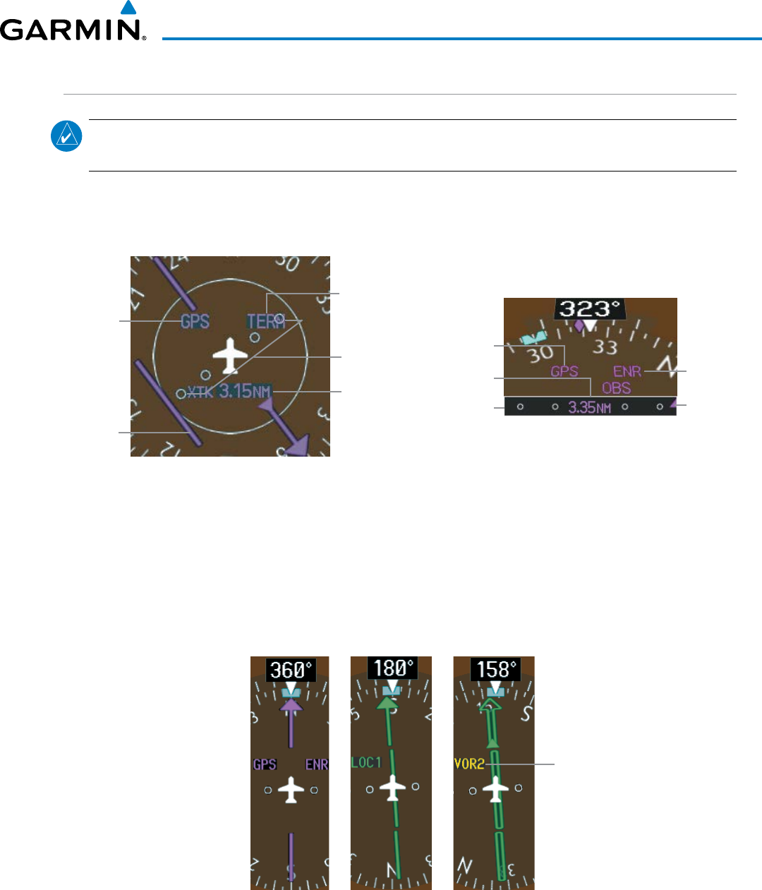
190-00928-04 Rev. A
Garmin G1000 Pilot’s Guide for the Beechcraft 200/B200 Series
73
FLIGHT INSTRUMENTS
COURSE DEVIATION INDICATOR (CDI)
NOTE
: If a heading change of greater than 105˚ with respect to the course is made, the CDI on the Arc HSI
switches to the opposite side of the deviation scale and displays reverse sensing.
The Course Deviation Indicator (CDI) moves left or right from the course pointer along a lateral deviation
scale to display aircraft position relative to the course. If the course deviation data is not valid, the CDI is not
displayed.
Figure 2-25 Course Deviation Indicator
360º HSI
Scale
Crosstrack
Error
Flight
Phase
CDI
Navigation
Source
Arc HSI
CDI
Navigation
Source
CDI Scale
Flight
Phase
Crosstrack
Error
The CDI can display two sources of navigation: GPS or NAV (VOR, localizer). Color indicates the current
navigation source: magenta (for GPS) or green (for VOR and LOC); the Selected Course readout also follows
these color indications. When coupled to GPS, the full scale limits for the CDI are defined by a GPS-derived
distance. When coupled to a VOR or localizer (LOC), the CDI has the same angular limits as a mechanical CDI.
If the CDI exceeds the maximum deviation on the scale (two dots) while coupled to GPS, the crosstrack error
(XTK) is displayed below the white aircraft symbol.
Figure 2-26 Navigation Sources
Navigation
Source Selected
on Both PFDs
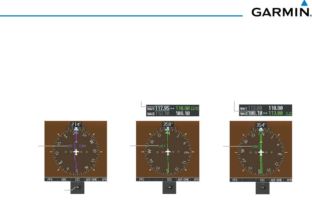
Garmin G1000 Pilot’s Guide for the Beechcraft 200/B200 Series
190-00928-04 Rev. A74
FLIGHT INSTRUMENTS
Changing navigation sources:
1) Select the CDI Softkey to change from GPS to VOR1 or LOC1. This places the light blue tuning box over the
NAV1 standby frequency in the upper left corner of the PFD.
2) Select the CDI Softkey again to change from VOR1 or LOC1 to VOR2 or LOC2. This places the light blue tuning
box over the NAV2 standby frequency.
3) Select the CDI Softkey a third time to return to GPS.
Selecting the
CDI
Softkey
Cycles through
Navigation Sources
GPS
Selected
Figure 2-27 Selecting a Navigation Source
LOC1
Selected
NAV1 Selected for Tuning
VOR2
Selected
NAV2 Selected for Tuning
If the same VOR/LOC navigation source is selected on both PFDs, the navigation source annunciation turns
yellow on both displays (unless synchronized). Once the CDIs are synchronized (CDI SYNC turned on), they
remain synchronized until the setting is turned off.
Synchronizing the CDIs:
1) Turn the large FMS Knob to select the AUX page group on the MFD.
2) Turn the small FMS Knob to select the System Setup Page.
3) If necessary, press the SETUP 1 Softkey to display the System Setup 1 Page.
4) Press the
FMS
Knob to activate the cursor.
5) Turn the
large FMS
Knob to highlight the ‘CDI Sync’ in the Synchronization box.
6) Turn the
small FMS
Knob clockwise to ON or counterclockwise to OFF.
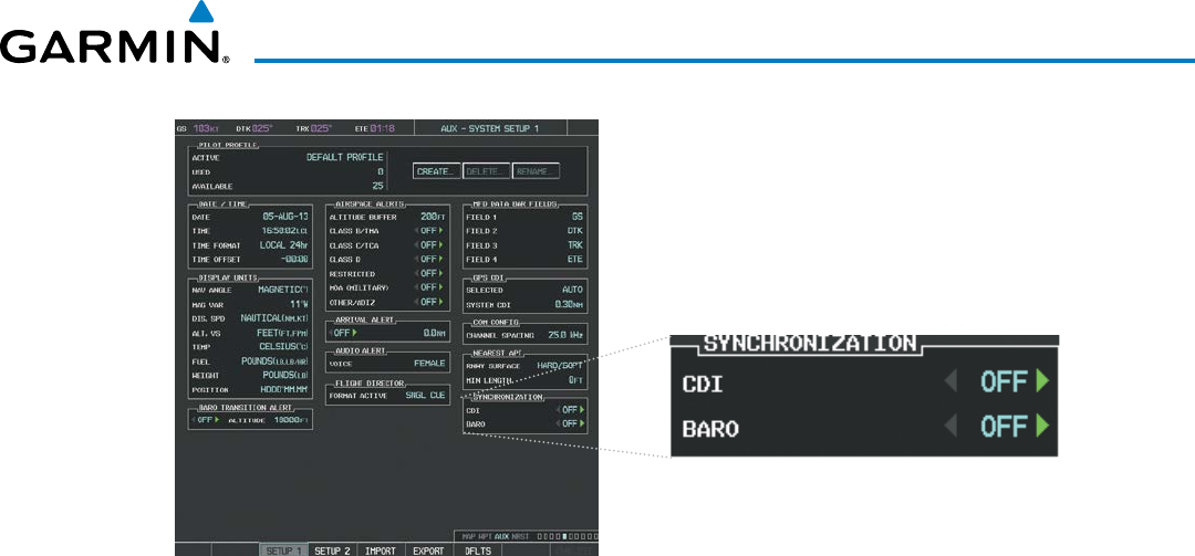
190-00928-04 Rev. A
Garmin G1000 Pilot’s Guide for the Beechcraft 200/B200 Series
75
FLIGHT INSTRUMENTS
Figure 2-28 System Setup Page, CDI Synchronization
The system automatically switches from GPS to LOC navigation source and changes the CDI scaling accordingly
when all of the following occur:
• A localizer or ILS approach has been loaded into the active flight plan
• The final approach fix (FAF) is the active leg, the FAF is less than 15 nm away, and the aircraft is moving
toward the FAF
• A valid localizer frequency has been tuned
• The GPS CDI deviation is less than 1.2 times full-scale deflection
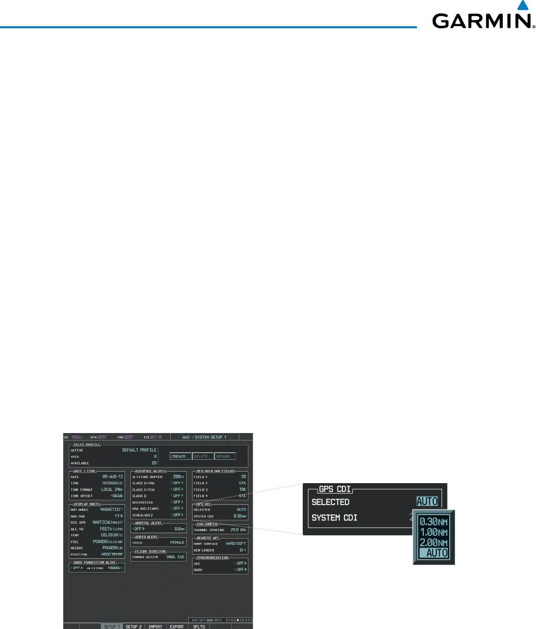
Garmin G1000 Pilot’s Guide for the Beechcraft 200/B200 Series
190-00928-04 Rev. A76
FLIGHT INSTRUMENTS
GPS steering guidance is still provided after the CDI automatically switches to LOC until LOC capture, up
to the Final Approach Fix (FAF) for an ILS approach, or until GPS information becomes invalid. Activating
a Vector-to-Final (VTF; see the Flight Management Section) also causes the CDI to switch to LOC navigation
source; GPS steering guidance is not provided after this switch.
GPS CDI SCALING
When GPS is the selected navigation source, the flight plan legs are sequenced automatically and
annunciations appear on the HSI for the flight phase. Flight phase annunciations are normally shown in
magenta, but when cautionary conditions exist the color changes to yellow. If the current leg in the flight plan
is a heading leg, ‘HDG LEG’ is annunciated in magenta beneath the aircraft symbol.
The current GPS CDI scale setting is displayed as ‘System CDI’ on the AUX - System Setup 1 Page and the
full-scale deflection setting may also be changed (2.0 nm, 1.0 nm, 0.3 nm, or Auto) from this page (
Figure
2-29
). If the selected scaling is smaller than the automatic setting for enroute and terminal phases, the CDI is
scaled accordingly and the selected setting is be displayed rather than the flight phase annunciation.
Changing the selected GPS CDI setting:
1) Turn the large FMS Knob to select the AUX page group on the MFD.
2) Turn the small FMS Knob to select the System Setup Page.
3) If necessary, press the SETUP 1 Softkey to display the System Setup 1 Page.
4) Press the FMS Knob to activate the cursor.
5) Turn the
large FMS
Knob to highlight ‘Selected’ in the ‘GPS CDI’ box.
6) Turn the small FMS Knob to highlight the desired setting and press the ENT Key.
7) To cancel the selection, press the FMS Knob or the CLR Key.
Figure 2-29 System Setup Page, GPS CDI Settings
When set to ‘Auto’ (default), the GPS CDI scale automatically adjusts to the desired limits based upon the
current phase of flight (Figure 2-30, 2-31, 2-32, Table 2-2).
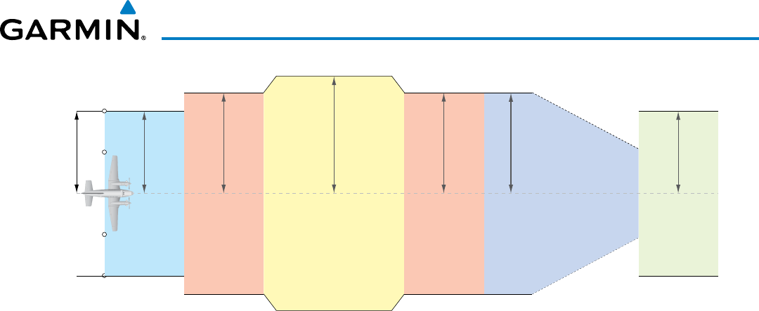
190-00928-04 Rev. A
Garmin G1000 Pilot’s Guide for the Beechcraft 200/B200 Series
77
FLIGHT INSTRUMENTS
Figure 2-30 Automatic CDI Scaling
0.3 nm
Missed
Approach
Approach
2.0 nm
Enroute
1.0 nm
1.0 nm
Te rminal
1.0 nm
Te rminal
0.3 nm
Departure
CDI Full-scale Deflection
Refer to accompanying
approach CDI scaling figures
• When a departure procedure is active, the CDI is scaled for departure (0.3 nm).
• The system switches from departure to terminal CDI scaling (1.0 nm) under the following conditions:
- The next leg in the procedure is not aligned with the departure runway
-
The next leg in the departure procedure is not CA, CD, CF, CI, CR, DF, FA, FC, FD, FM, IF, or TF (see
Glossary for leg type definitions)
- After any leg in the departure procedure that is not CA or FA
• At 30 nm from the departure airport the enroute phase of flight is automatically entered and CDI scaling
changes to 2.0 nm over a distance of 1.0 nm, except under the following conditions:
- When navigating with an active departure procedure, the flight phase and CDI scale does not change
until the aircraft arrives at the last departure waypoint (if more than 30 nm from the departure airport)
or the leg after the last departure waypoint has been activated or a direct-to waypoint is activated.
• If after completing the departure procedure the nearest airport is more than 200 nm away from the aircraft
and the approach procedure has not yet commenced, the CDI is scaled for oceanic flight (4.0 nm).
• Within 31 nm of the destination airport (terminal area), the CDI scale gradually ramps down from 2.0 nm
to 1.0 nm over a distance of 1.0 nm; except under the following conditions:
- Upon reaching the first waypoint of an arrival route that is more than 31 nm from the destination airport,
the flight phase changes to terminal and the CDI scale begins to transition down from 2.0 nm to 1.0 nm
over a distance of 1.0 nm.
• During approach, the CDI scale ramps down even further (see Figures 2-31 and 2-32). This transition
normally occurs within 2.0 nm of the final approach fix (FAF). The CDI switches to approach scaling
automatically once the approach procedure is activated or if Vector-to-Final (VTF) is selected.
- If the active waypoint is the FAF, the ground track and the bearing to the FAF must be within 45° of the
final approach segment course.
- If the active waypoint is part of the missed approach procedure, the active leg and preceding missed
approach legs must be aligned with the final approach segment course and the aircraft must not have
passed the turn initiation point.
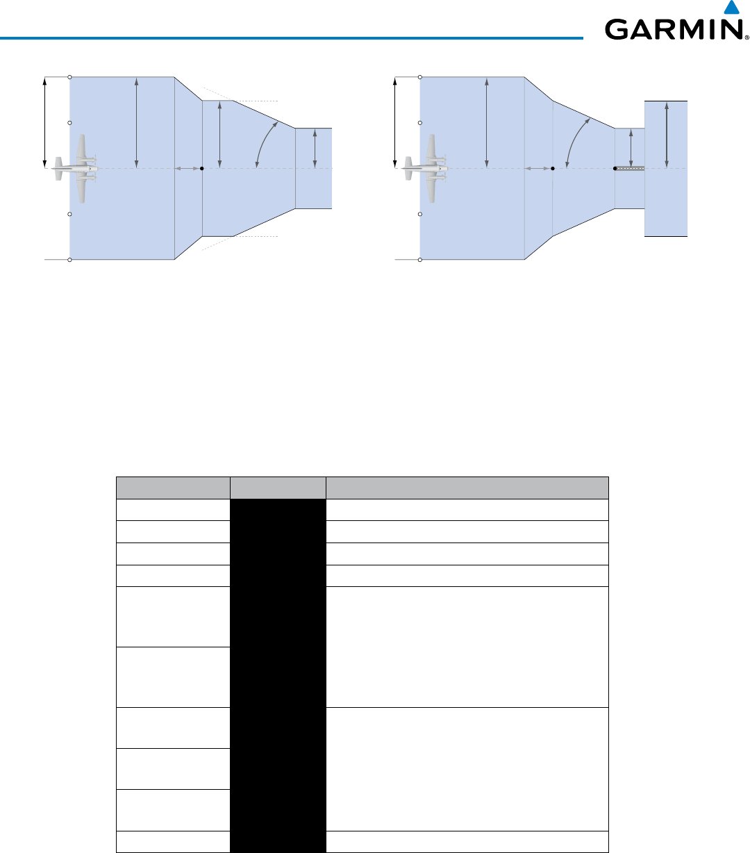
Garmin G1000 Pilot’s Guide for the Beechcraft 200/B200 Series
190-00928-04 Rev. A78
FLIGHT INSTRUMENTS
Figure 2-31 Typical LNAV and LNAV+V Approach CDI Scaling
1.0 nm
2 nm
350 ft
angle set
by system
0.3 nm
FAF
CDI Full-scale Deflection
CDI scale is set to the smaller of 0.3 nm
or an angle set by the system
CDI scale varies if VTF is activated
Figure 2-32 Typical LNAV/VNAV, LP, and LPV Approach CDI Scaling
1.0 nm
2 nm
FAF
0.3 nm
course width
Landing
Threshold
CDI Full-scale Deflection
angle based
on database
information
CDI scale varies if VTF is activated
• When a missed approach is activated, the CDI scale changes to 0.3 nm.
• The system automatically switches back to terminal scaling under the following conditions:
- The next leg in the missed approach procedure is not aligned with the final approach path
-
The next leg in the missed approach procedure is not CA, CD, CF, CI, CR, DF, FA, FC, FD, FM, IF, or TF
- After any leg in the missed approach procedure that is not CA or FA
Flight Phase Annunciation Automatic CDI Full-scale Deflection
Departure DPRT 0.3 nm
Terminal TERM 1.0 nm
Enroute ENR 2.0 nm
Oceanic OCN 4.0 nm
Approach
(Non-precision) LNAV
1.0 nm decreasing to 350 feet depending on
variables (see Figure 2-31)
Approach
(Non-precision with
Vertical Guidance)
LNAV + V
Approach
(LNAV/VNAV) L/VNAV
1.0 nm decreasing to a specified course width, then
0.3 nm, depending on variables (see Figure 2-32)
Approach
(LPV) LPV
Approach
(LP) LP
Missed Approach MAPR 0.3 nm
Table 2-2 Automatic GPS CDI Scaling
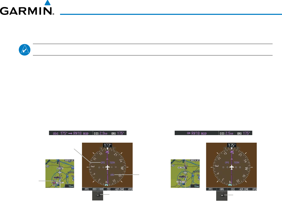
190-00928-04 Rev. A
Garmin G1000 Pilot’s Guide for the Beechcraft 200/B200 Series
79
FLIGHT INSTRUMENTS
OBS MODE
NOTE: VNV is inhibited while automatic waypoint sequencing has been suspended.
Enabling Omni-bearing Selector (OBS) Mode suspends the automatic sequencing of waypoints in a GPS
flight plan (GPS must be the selected navigation source), but retains the current “active-to” waypoint as the
navigation reference even after passing the waypoint. ‘OBS’ is annunciated to the lower right of the aircraft
symbol when OBS Mode is selected (see Figure 2-33).
While OBS Mode is enabled, a course line is drawn through the “active-to” waypoint on the moving map.
If desired, the course to/from the waypoint can now be adjusted. When OBS Mode is disabled, the GPS flight
plan returns to normal operation with automatic sequencing of waypoints, following the course set in OBS
Mode. The flight path on the moving map retains the modified course line.
Figure 2-33 Omni-bearing Selector (OBS) Mode
Pressing the
OBS
Softkey Again
Disables OBS Mode
Extended
Course
Line
GPS
Selected
OBS Mode
Enabled
Pressing the
OBS
Softkey Enables
OBS Mode
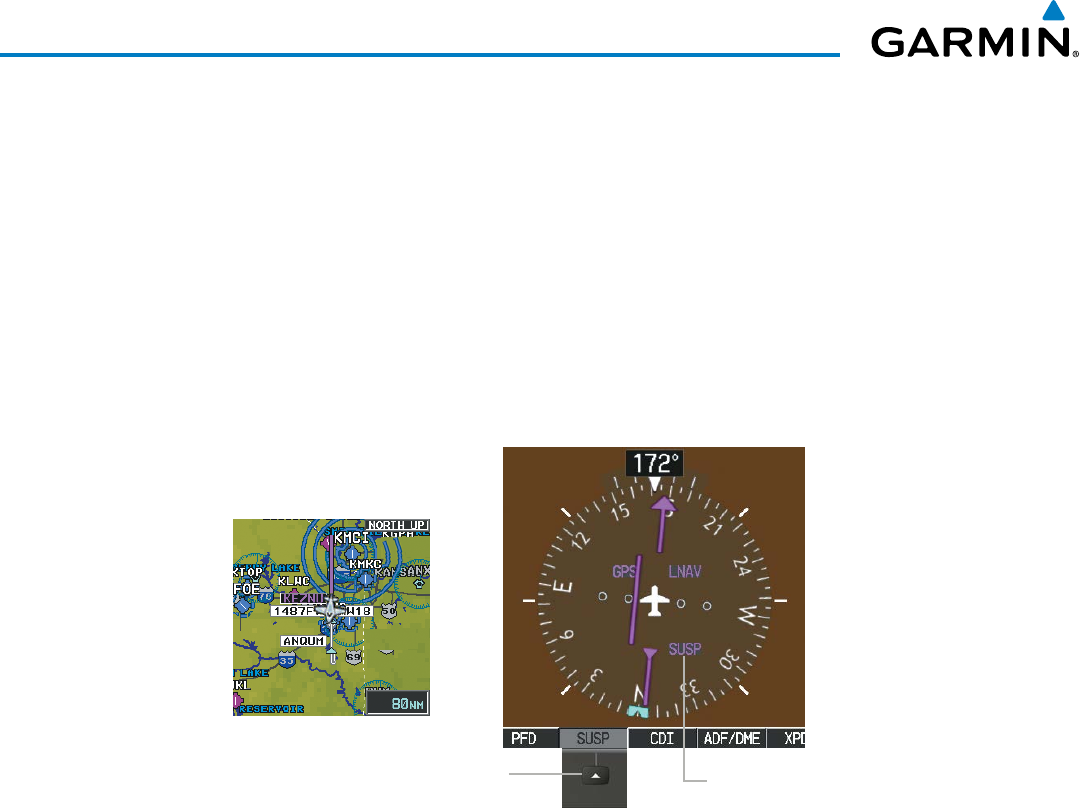
Garmin G1000 Pilot’s Guide for the Beechcraft 200/B200 Series
190-00928-04 Rev. A80
FLIGHT INSTRUMENTS
Enabling/disabling OBS Mode while navigating a GPS flight plan:
1) Select the OBS Softkey to select OBS Mode.
2) Turn the CRS Knob to select the desired course to/from the waypoint. Press the CRS Knob to synchronize the
Selected Course with the bearing to the next waypoint.
3) Select the OBS Softkey again to return to automatic waypoint sequencing.
As the aircraft crosses the missed approach point (MAP), automatic approach waypoint sequencing is
suspended. SUSP appears on the HSI at the lower right of the aircraft symbol. The
OBS
Softkey label
changes to indicate the suspension is active as shown in Figure 2-34. Pressing the SUSP Softkey deactivates
the suspension and resumes automatic sequencing of approach waypoints.
Figure 2-34 Suspending Automatic Waypoint Sequencing
SUSP
Softkey SUSP
Annunciation
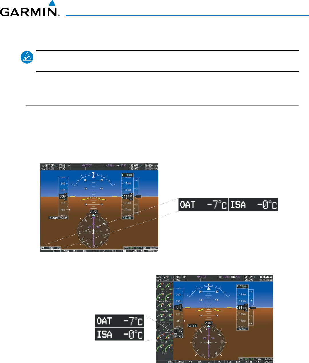
190-00928-04 Rev. A
Garmin G1000 Pilot’s Guide for the Beechcraft 200/B200 Series
81
FLIGHT INSTRUMENTS
2.2 SUPPLEMENTAL FLIGHT DATA
NOTE: Selecting the DFLTS Softkey (a second-level PFD softkey) turns off metric Altimeter display, the Inset
Map, and wind data display.
In addition to the flight instruments, the PFD also displays various supplemental information, including
temperatures, wind data, and Vertical Navigation (VNV) indications.
TEMPERATURE DISPLAYS
The G1000 Outside Air Temperature display (OAT), which is adjusted for compressibility effects, and the
deviation from International Standard Atmosphere Temperature display (ISA) are shown in degrees Celsius
(°C) by default in the lower left of the PFD under normal display conditions, or below the true airspeed in
reversionary mode.
Figure 2-35 Outside Air Temperature
Normal Display
Reversionary Mode
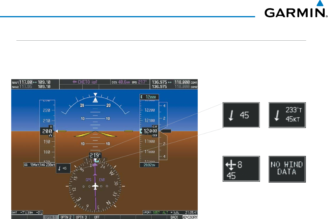
Garmin G1000 Pilot’s Guide for the Beechcraft 200/B200 Series
190-00928-04 Rev. A82
FLIGHT INSTRUMENTS
WIND DATA
Wind direction and speed in knots can be displayed in a window to the upper left of the HSI. When the
window is selected for display, but wind information is invalid or unavailable, the window shows “NO WIND
DATA”. Wind data can be displayed in three different ways:
Figure 2-36 Wind Data
No Data
Option 2
Option 1
Option 3
Displaying wind data:
1) Press the PFD Softkey.
2) Press the WIND Softkey to display wind data below the Selected Heading.
3) Press one of the OPTN softkeys to change how wind data is displayed:
• OPTN 1: Wind direction arrow and speed
• OPTN 2: Wind direction arrow with true digital direction and speed
• OPTN 3: Wind direction arrows with headwind, tailwind, and crosswind speed components
4) To remove the window, press the OFF Softkey.
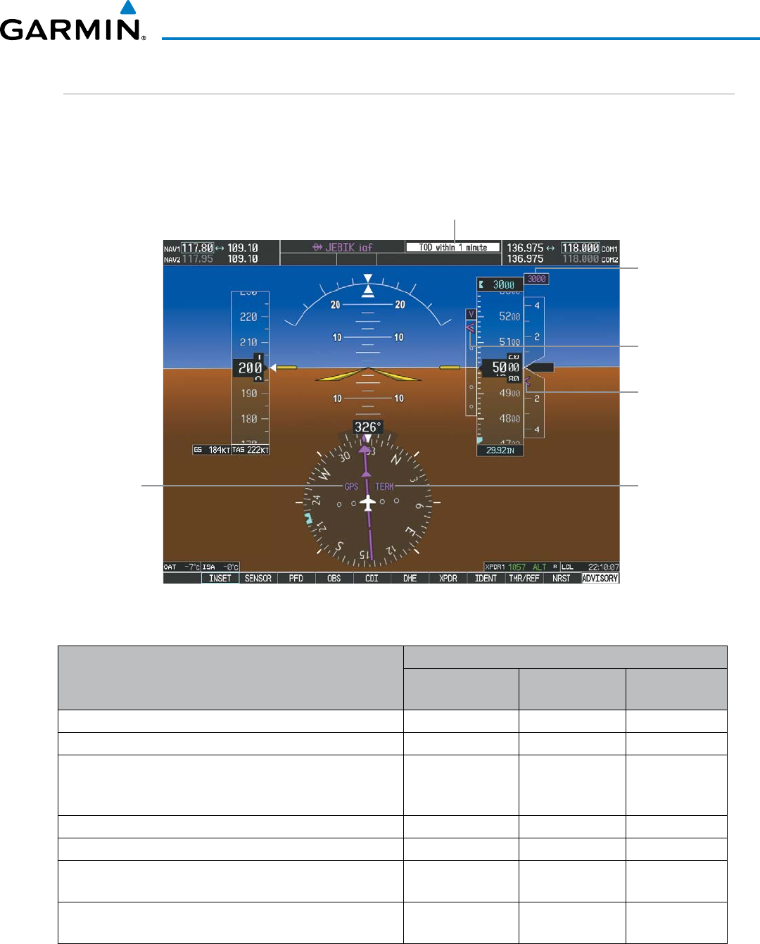
190-00928-04 Rev. A
Garmin G1000 Pilot’s Guide for the Beechcraft 200/B200 Series
83
FLIGHT INSTRUMENTS
VERTICAL NAVIGATION (VNV) INDICATIONS
When a VNV flight plan has been activated, VNV indications (VNV Target Altitude, RVSI, VDI) appear on the
PFD in conjunction with the “TOD within 1 minute” message and “Vertical track” voice alert. See the Flight
Management and AFCS sections for details on VNV features. VNV indications are removed from the PFD
according to the criteria listed in Table 2-3.
Figure 2-37 Vertical Navigation Indications (PFD)
Top of Descent Message
VNV Target
Altitude
Vertical
Deviation
Indicator
Required
Vertical
Speed Bug
GPS is
Selected
Navigation
Source
Phase of
Flight
Criteria
VNV Indication Removed
Required Vertical
Speed (RVSI)
Vertical
Deviation (VDI)
VNV Target
Altitude
Aircraft > 1 min before the next TOD due to flight plan change X X X
VNV cancelled (CNCL VNV Softkey selected on MFD) X X X
Distance to active waypoint cannot be computed due to
unsupported flight plan leg type (see Flight Management
Section)
X X X
Aircraft > 250 feet below active VNV Target Altitude X X X
Current crosstrack or track angle error has exceeded limit X X X
Active altitude-constrained waypoint cannot be reached within
maximum allowed flight path angle and vertical speed X X
Last altitude-constrained waypoint in active flight plan reached X X
(30 sec before) X
Table 2-3 VNV Indication Removal Criteria
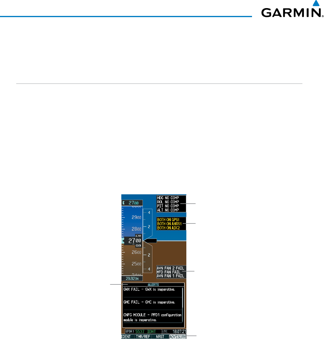
Garmin G1000 Pilot’s Guide for the Beechcraft 200/B200 Series
190-00928-04 Rev. A84
FLIGHT INSTRUMENTS
2.3 PFD ANNUNCIATIONS AND ALERTING FUNCTIONS
The following annunciations and alerting functions are displayed on the PFD. Refer to Appendix A for more
information on alerts and annunciations.
G1000 ALERTING SYSTEM
Messages appear in the Alerts Window (in the lower right corner of the PFD; Figure 2-38) when a warning,
caution, advisory alert, or G1000 message advisory occurs. System alert messages are provided for awareness
of G1000 system problems or status and may not require pilot action. The Alerts Window allows system alerts
to be displayed simultaneously. The FMS Knob can be used to scroll through the alert messages. The Alerts
Window is enabled/disabled by selecting the
ALERTS
Softkey. If the window is already open when a new
message is generated, selecting the ALERTS Softkey to acknowledge the message causes it to turn gray.
The Annunciation Window appears to the right of the Vertical Speed Indicator and displays abbreviated
annunciation text for aircraft alerts. Text color is based on alert level: warnings appear in red, cautions in
yellow, advisory alerts in white. New alerts, regardless of priority, are displayed at the top of the Annunciation
Window, separated by a white line from acknowledged alerts. Once acknowledged, they are sequenced based
on priority.
Alerts
Window
Softkey
Annunciation
Reversionary
Sensor
Window
Comparator
Window
Figure 2-38 G1000 Alerting System
Annunciation
Window
The ADVISORY Softkey provides general information to the pilot that may not need immediate attention.
A flashing ADVISORY Softkey annunciation (no aural tone) indicates the presence of a message advisory. The
flashing ADVISORY Softkey annunciation continues to flash until acknowledged (by pressing the
ADVISORY
Softkey).
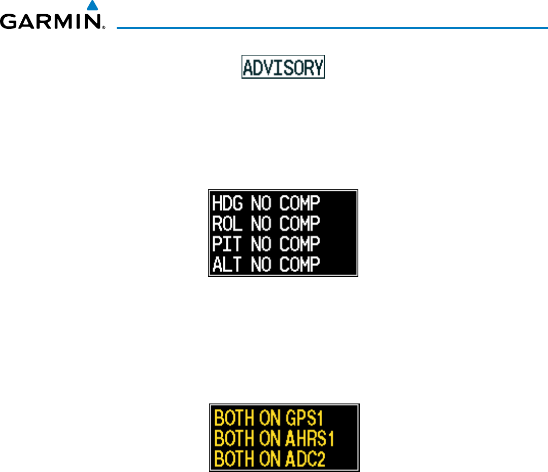
190-00928-04 Rev. A
Garmin G1000 Pilot’s Guide for the Beechcraft 200/B200 Series
85
FLIGHT INSTRUMENTS
Figure 2-39 Softkey Annunciation
Critical values generated by redundant sensors are monitored by comparators. If differences in the sensors
exceed a specified amount, the Comparator Window appears in the upper right corner of the PFD and the
discrepancy is annunciated in the Comparator Window as a ‘MISCOMP’ (miscompare). If one or both of the
sensed values are unavailable, it is annunciated as a ‘NO COMP’ (no compare).
Figure 2-40 Comparator Window
Reversionary sensor selection is annunciated in a window on the right side of the PFD. These annunciations
reflect reversionary sensors selected on one or both PFDs. Pressing the SENSOR Softkey accesses the ADC1,
ADC2, AHRS1, and AHRS2 softkeys. These softkeys allow switching of the sensors being viewed on each
PFD. With certain types of sensor failures, the G1000 may make some sensor selections automatically. The GPS
sensor cannot be switched manually.
Figure 2-41 Reversionary Sensor Window
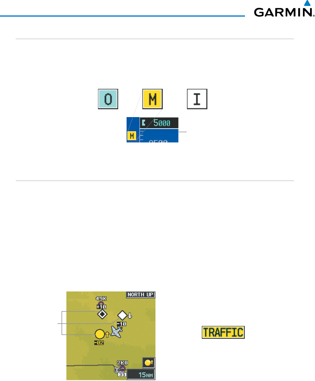
Garmin G1000 Pilot’s Guide for the Beechcraft 200/B200 Series
190-00928-04 Rev. A86
FLIGHT INSTRUMENTS
MARKER BEACON ANNUNCIATIONS
Marker Beacon Annunciations are displayed on the PFD to the left of the Selected Altitude. Outer marker
reception is indicated in blue, middle in yellow, and inner in white. Refer to the Audio Panel and CNS Section
for more information on Marker Beacon Annunciations.
Figure 2-42 Marker Beacon Annunciations
Inner MarkerMiddle MarkerOuter Marker
Altimeter
TRAFFIC ANNUNCIATION
The System displays traffic symbolically on the Inset Map (PFD), the Navigation Map Page (MFD), and various
other MFD page maps. Refer to the Hazard Avoidance Section for more details about the Traffic Information
Service (TIS) and optional Traffic Advisory Systems (TAS). When a traffic advisory (TA) is detected, the following
automatically occurs:
• The PFD Inset Map is enabled, displaying traffic (Figure 2-43)
• A flashing black-on-yellow TRAFFIC annunciation (Figure 2-44) appears to the top left of the Attitude
Indicator for five seconds and remains displayed until no TAs are detected in the area
• A single “Traffic” aural alert is generated, unless an optional Traffic Advisory System (TAS) is installed (refer to
the applicable TAS documentation for alerts generated by TAS equipment)
If additional TAs appear, new aural and visual alerts are generated.
Figure 2-44 Traffic Annunciation
Figure 2-43 Inset Map with Traffic Displayed
Traffic
Symbols
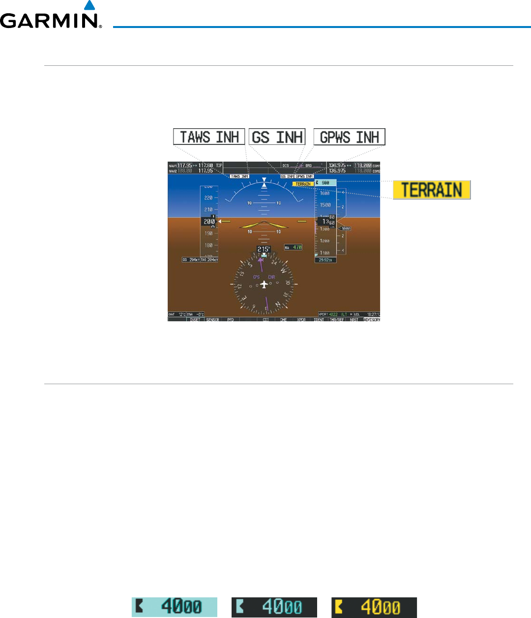
190-00928-04 Rev. A
Garmin G1000 Pilot’s Guide for the Beechcraft 200/B200 Series
87
FLIGHT INSTRUMENTS
TAWS ANNUNCIATIONS
Terrain Awareness and Warning System (TAWS) annunciations appear on the PFD to the upper left of the
Altimeter. In TAWS-A installations, annunciations also appear to the upper right of the Airspeed Indicator.
Refer to the Hazard Avoidance Section and Appendix A for information on TAWS alerts and annunciations.
Figure 2-45 Example TAWS-A Annunciations
ALTITUDE ALERTING
The Altitude Alerting function provides the pilot with visual and aural alerts when approaching the Selected
Altitude. Whenever the Selected Altitude is changed, the Altitude Alerter is reset. The Altitude Alerter is
independent of the GFC 700 AFCS, but aural and visual alerts are generated only when the GFC 700 is
installed. The following occur when approaching the Selected Altitude:
• Upon passing through 1000 feet of the Selected Altitude, the Selected Altitude (shown above the Altimeter)
changes to black text on a light blue background, flashes for 5 seconds, and an aural tone is generated.
• When the aircraft passes within 200 ft of the Selected Altitude, the Selected Altitude changes to light blue text
on a black background and flashes for 5 seconds.
• After reaching the Selected Altitude, if the pilot flies outside the deviation band (±200 feet of the Selected
Altitude), the Selected Altitude changes to yellow text on a black background, flashes for 5 seconds, and an
aural tone is generated.
Figure 2-46 Altitude Alerting Visual Annunciations
Within 1000 ft Within 200 ft Deviation of ±200 ft
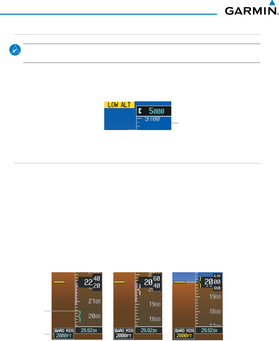
Garmin G1000 Pilot’s Guide for the Beechcraft 200/B200 Series
190-00928-04 Rev. A88
FLIGHT INSTRUMENTS
LOW ALTITUDE ANNUNCIATION
NOTE: The Low Altitude Annunciation is available only when an SBAS signal (such as WAAS, EGNOS, or
MSAS) is available and the pilot has inhibited TAWS alerts.
When the Final Approach Fix (FAF) is the active waypoint in a GPS SBAS approach using vertical guidance,
a Low Altitude Annunciation may appear if the current aircraft altitude is at least 164 feet below the prescribed
altitude at the FAF. A black-on-yellow ‘LOW ALT’ annunciation appears to the top right of the Altimeter,
flashing for several seconds then remaining displayed until the condition is resolved.
Figure 2-47 Low Altitude on GPS SBAS Approach
Altimeter
MINIMUM DESCENT ALTITUDE/DECISION HEIGHT ALERTING
For altitude awareness, a barometric, radar altimeter, or temperature compensated Minimum Descent Altitude
(MDA) or Decision Height (DH) can be set in the Timer/References Window and is reset when the power is
cycled. When active, the altitude setting is displayed to the bottom left of the Altimeter. Once the altitude
is within the range of the tape, a bug appears at the reference altitude on the Altimeter. The following visual
annunciations occur when approaching the MDA/DH:
• When the aircraft altitude descends to within 2500 feet of the MDA/DH setting, the BARO MIN, RA MIN, or
COMP MIN box appears with the altitude in light blue (or magenta for COMP MIN) text. The bug appears
on the altitude tape in light blue (or magenta for COMP MIN) once in range.
• When the aircraft passes through 100 feet of the MDA/DH, the bug and text turn white.
• Once the aircraft reaches MDA/DH, the bug and text turn yellow and the aural alert, “Minimums. Minimums”,
is heard.
Figure 2-48 Barometric MDA/DH Alerting Visual Annunciations
Within 100 ft Altitude Reached
Within 2500 ft
Barometric
Minimum
Box
Barometric
Minimum
Bug
Alerting is inhibited while the aircraft is on the ground and until the aircraft reaches 150 feet above the MDA.
If the aircraft proceeds to climb after having reached the MDA, once it reaches 50 feet above the MDA, alerting
is disabled.
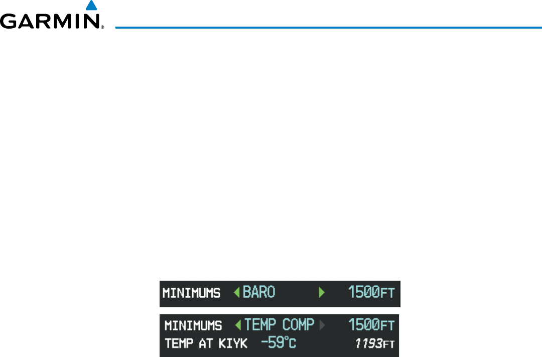
190-00928-04 Rev. A
Garmin G1000 Pilot’s Guide for the Beechcraft 200/B200 Series
89
FLIGHT INSTRUMENTS
The MDA/DH may be set from either PFD and is synchronized on both PFDs. The function is reset when the
power is cycled or a new approach is activated.
Setting the barometric Minimum Descent Altitude/Decision Height and bug:
1) Press the
TMR/REF
Softkey.
2) Turn the large FMS Knob to highlight the Minimums field.
3) Turn the small FMS Knob to select BARO, TEMP COMP, or RAD ALT. OFF is selected by default. Press the ENT
Key or turn the large FMS Knob to highlight the next field.
4) Use the small FMS Knob to enter the desired altitude (from zero to 16,000 feet when BARO or TEMP COMP is
selected, or up to 2,500 feet when ‘RAD ALT’ is selected).
5) If TEMP COMP was selected, press the ENT Key or turn the large FMS Knob to highlight the next field and then
enter the temperature (-59˚C to 59˚C)
6) To remove the window, press the
CLR
Key or the
TMR/REF
Softkey.
Figure 2-49 BARO and TEMP COMP MDA/DH
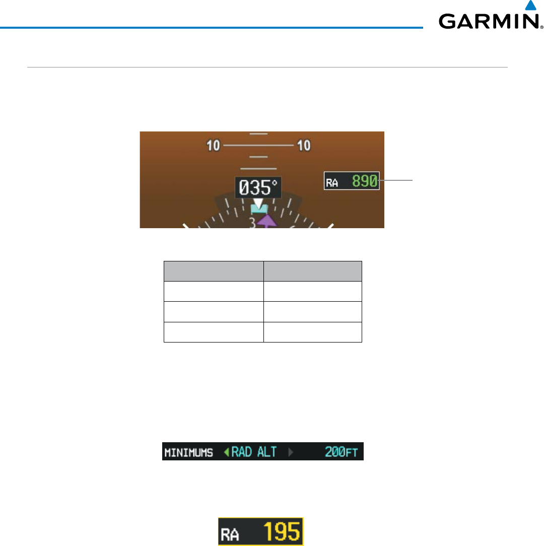
Garmin G1000 Pilot’s Guide for the Beechcraft 200/B200 Series
190-00928-04 Rev. A90
FLIGHT INSTRUMENTS
RADAR ALTIMETER
When the radar height (the aircraft altitude above ground level detected by the radar altimeter) is between
zero and 2500 feet, the current value is displayed in green to the right of the current aircraft heading (Figure
2-50). Display of radar height becomes more sensitive as the height above ground decreases (Table 2-4).
Figure 2-50 Current Radar Height
Radar Altimeter
Radar Height Range Shown to Nearest
0 to 200 feet 5 feet
200 to 1500 feet 10 feet
1500 to 2500 feet 50 feet
Table 2-4 Radar Altimeter Sensitivity
When the radar altimeter is selected as the altitude source for the minimum descent altitude alerting function
(Figure 2-51), the color of the radar height changes to yellow upon reaching at or below the MDA/DH (Figure
2-52).
Figure 2-51 RAD ALT Setting
(Timer/References Window)
Figure 2-52 RA as Altitude Source for MDA/DH
A ground line (Figure 2-53) is shown on the Altimeter to display the aircraft’s height relative to the ground.
If the data becomes invalid, the message “RA FAIL” is displayed in yellow in the RA box (Figure 2-54). The
Radar Altimeter test is done on the MFD but is displayed on the PFDs to the right of the current heading (Figure
2-55).
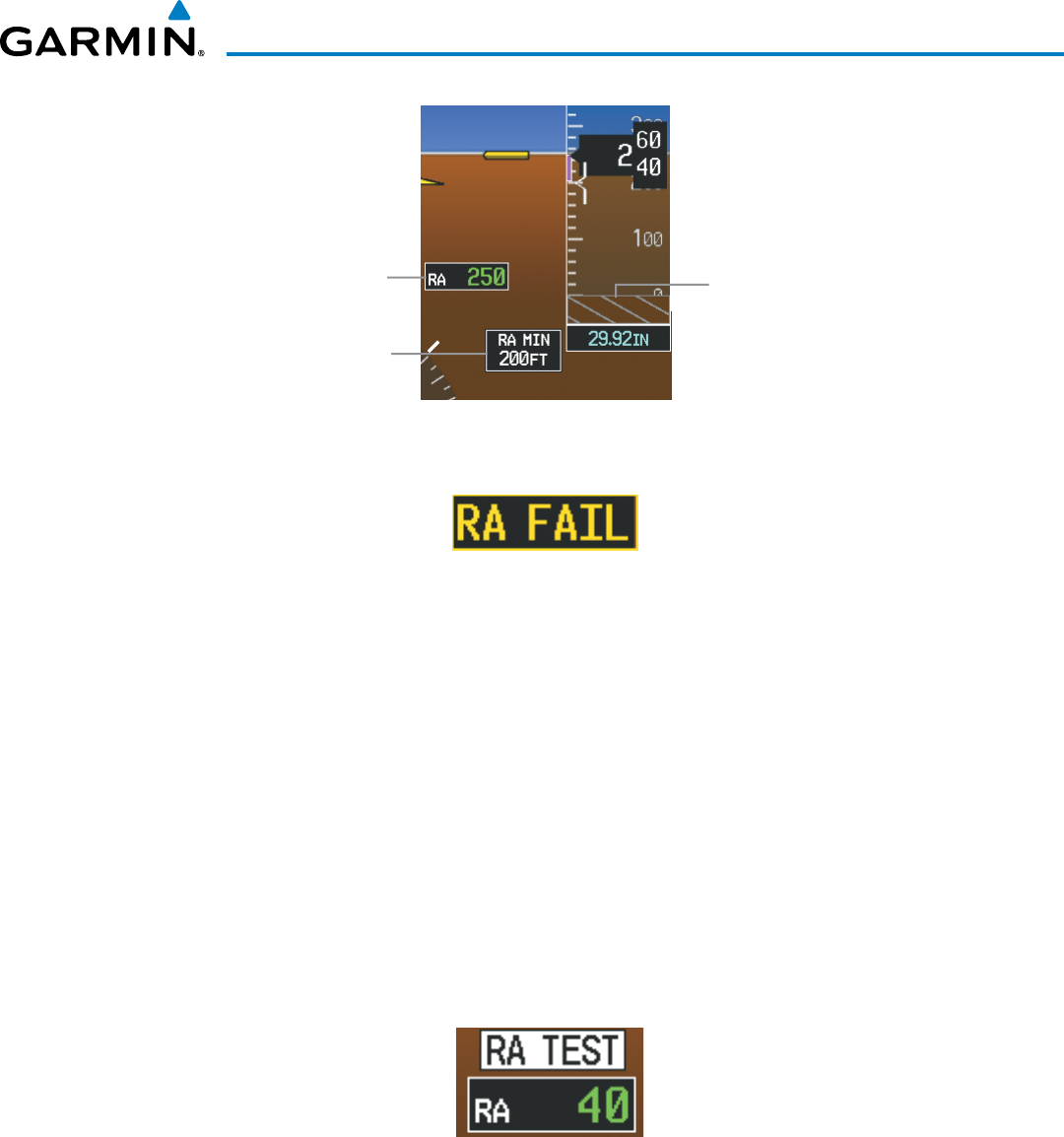
190-00928-04 Rev. A
Garmin G1000 Pilot’s Guide for the Beechcraft 200/B200 Series
91
FLIGHT INSTRUMENTS
Radar Altimeter
Minimums Box
Ground
Line
Radar
Altimeter
Figure 2-53 Altimeter Displaying the Ground Line (RAD ALT)
Figure 2-54 Radar Altimeter with Invalid Data
Enabling/Disabling the Radar Altimeter Test Mode:
1) Turn the large FMS Knob to select the AUX page group on the MFD.
2) Turn the small FMS Knob to select the AUX - System Status Page.
3) Press the RA TEST Softkey to enable or disable the test.
Or:
1) Press the MENU Key.
2) Turn the
small
FMS Knob to choose ‘Enable RA Test Mode’ or ‘Disable RA Test Mode’ (choice dependent on
current state).
3) Press the ENT Key.
When test mode is active, ‘RA TEST’ is annunciated above the RA box and 40 feet will be displayed in the
RA box.
Figure 2-55 Radar Altimeter with Test Annunciation
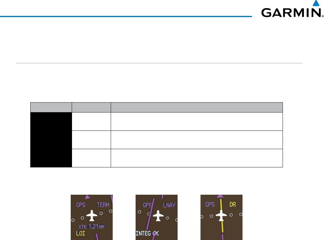
Garmin G1000 Pilot’s Guide for the Beechcraft 200/B200 Series
190-00928-04 Rev. A92
FLIGHT INSTRUMENTS
2.4 ABNORMAL OPERATIONS
ABNORMAL GPS CONDITIONS
The annunciations listed in Table 2-5 can appear on the HSI when abnormal GPS conditions occur; see Figure
2-56 for examples. Refer to the Flight Management Section for more information on Dead Reckoning (DR)
Mode.
Annunciation Location Description
LOI Lower left of
aircraft symbol
Loss of Integrity Monitoring–GPS integrity is insufficient for the current
phase of flight
INTEG OK Lower left of
aircraft symbol
Integrity OK–GPS integrity has been restored to within normal limits
(annunciation displayed for 5 seconds)
DR Upper right of
aircraft symbol
Dead Reckoning–System is using projected position rather than GPS position
to compute navigation data and sequence active flight plan waypoints
Table 2-5 Abnormal GPS Conditions Annunciated on HSI
Figure 2-56 Example HSI Annunciations
DR Mode causes the following items on the PFD to be shown in yellow:
• CDI (when GPS is the selected navigation source; removed after 20 minutes in DR mode operation)
• Current Track Indicator
• Wind data and pointers in the Wind Data Box on the PFD
• GPS bearing pointers
• Distances in the Bearing Information windows
• Active Flight Plan distances, bearings, and ETE values
The accuracy items should be verified when operating in DR Mode.
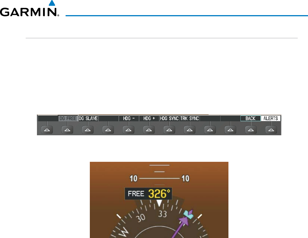
190-00928-04 Rev. A
Garmin G1000 Pilot’s Guide for the Beechcraft 200/B200 Series
93
FLIGHT INSTRUMENTS
DIRECTIONAL GYRO (DG) MODE
DG Mode allows the pilot to manually input a heading value. While DG Mode is not active, a yellow heading
value annunciation indicates that reliable magnetic variation data is unavailable.
Selecting DG Mode:
1) Press the PFD Softkey.
2) Press the HDG MODE Softkey.
3) Press the DG FREE Softkey to activate DG mode. Press the DG SLAVE Softkey to deactivate DG mode.
Figure 2-57 DG Mode Softkeys
Figure 2-58 DG Mode
Once active, ‘FREE’ is annunciated to the left of the heading value on the HSI. While in DG Mode and reliable
magnetic variation data is not available, the heading value is cyan. While in DG Mode and reliable magnetic
variation data is available, the heading value is yellow. The HDG-, HDG+, HDG SYNC, and TRACK SYNC keys
are enabled, and can be operated as follows:
• Pressing the HDG- or HDG+ softkey to slew the heading up or down.
• Pressing the HDG SYNC Bug softkey to sychronize the heading to the current selected heading
• Pressing the TRACK SYNC softkey to synchronize the heading to the current track
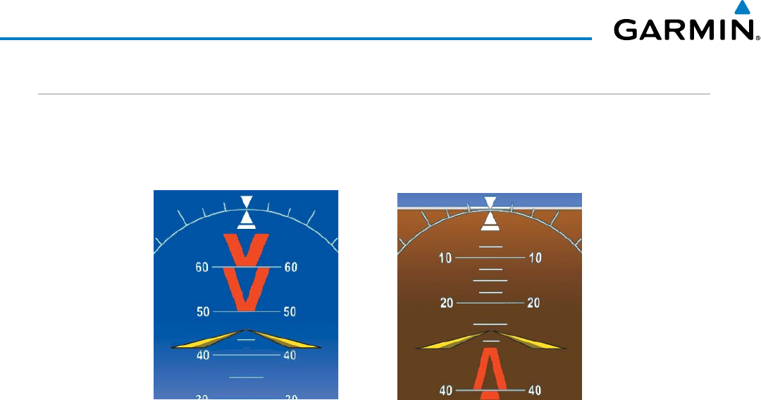
Garmin G1000 Pilot’s Guide for the Beechcraft 200/B200 Series
190-00928-04 Rev. A94
FLIGHT INSTRUMENTS
UNUSUAL ATTITUDES
When the aircraft enters an unusual pitch attitude, red extreme pitch warning chevrons pointing toward the
horizon are displayed on the Attitude Indicator, starting at 50˚ above and 30˚ below the horizon line.
Figure 2-59 Pitch Attitude Warnings
Nose Low
Nose High
If pitch exceeds +30˚/-20˚ or bank exceeds 65˚, some information displayed on the PFD is removed. The
Altimeter and Airspeed, Attitude, Vertical Speed, and Horizontal Situation indicators remain on the display
and the Bearing Information, Alerts, and Annunciation windows can be displayed during such situations. The
following information is removed from the PFD (and corresponding softkeys are disabled) when the aircraft
experiences unusual attitudes:
• Traffic Annunciations
• AFCS Annunciations
• Flight director Command Bars
• Inset Map
• Outside Air Temperature (OAT)
• International Standard
Atmosphere Temperature (ISA)
• DME Information Window
(optional)
• Wind data
• Transponder Status Box
• PFD Setup Menu
• Windows displayed in the lower
right corner of the PFD:
– Timer/References
– Nearest Airports
– Flight Plan
– Alerts
– Procedures
– DME Tuning (optional)
• Minimum Descent Altitude/
Decision Height readout
• Vertical Deviation, Glideslope,
and Glidepath Indicators
• Altimeter Barometric Setting
• Selected Altitude
• VNV Target Altitude
• System Time
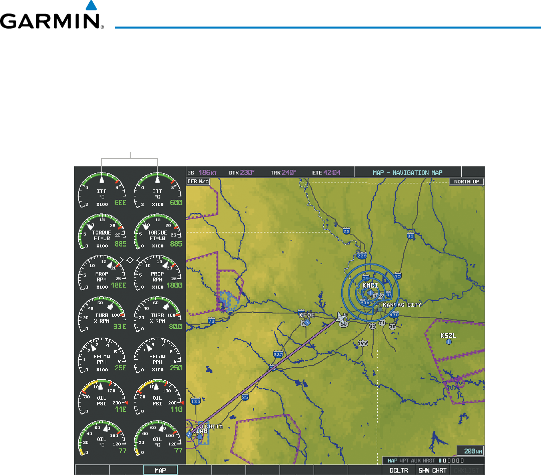
190-00928-04 Rev. A
Garmin G1000 Pilot’s Guide for the Beechcraft 200/B200 Series
95
ENGINE INDICATION SYSTEM
SECTION 3 ENGINE INDICATION SYSTEM
The G1000 Engine Indication System (EIS) displays critical engine and fuel flow parameters on the left side of
the Multi Function Display (MFD) during normal operations (Figure 3-1). In Reversionary Mode, the display(s)
are configured to combine the Primary Flight Display (PFD) symbology with the EIS (Figure 3-12).
EIS Display
Figure 3-1 MFD (Normal Mode)
EIS information is presented using gauges and digital readouts. Green bands on the instrument scales indicate
normal ranges of operation; yellow and red bands indicate caution and warning, respectively. White or uncolored
bands indicate areas outside of normal operation not yet in the caution or warning ranges (except for the Fuel
Flow gauges, which do not display bands). During normal operating conditions, an instrument’s pointer appears
in white and the readout text is green.
When an unsafe operating condition occurs, the pointer and readout color change to yellow or red, indicating
a caution or warning. If a cautionary time limit is exceeded, the pointers and digits may flash red, even if the
parameter is still within in the cautionary range. If the sensor data for a parameter becomes invalid or unavailable,
a red ‘X’ is displayed across the indicator and/or readout. If the sensor data for a parameter is out of range, dashes
‘---’ are displayed instead of a readout.
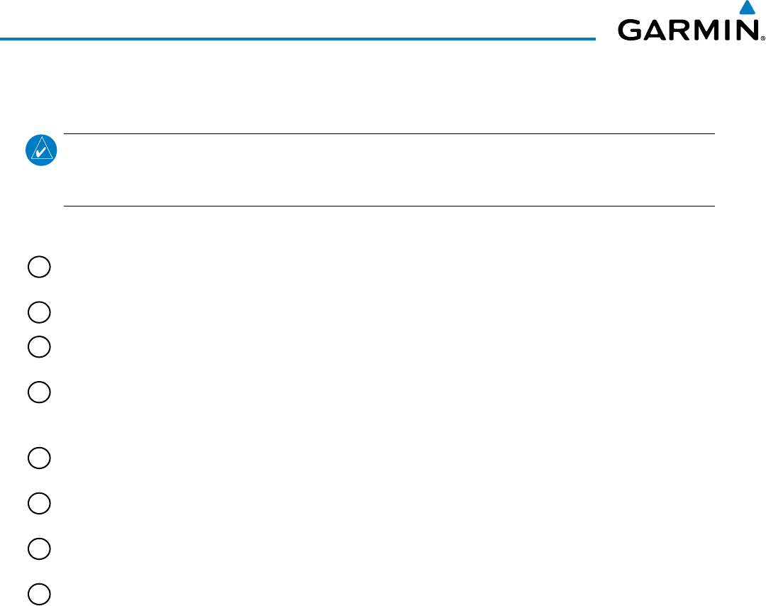
Garmin G1000 Pilot’s Guide for the Beechcraft 200/B200 Series
190-00928-04 Rev. A96
ENGINE INDICATION SYSTEM
3.1 EIS DISPLAY
NOTE: The gauges displayed and the values shown in this section are taken from an example Beechcraft
200/B200 configuration. Refer to the Pilot’s Operating Handbook (POH) and FAA Approved Airplane Flight
Manual (AFM) for specific values and operating limitations.
1
Interstage Turbine
Temperature (ITT)
Displays Interstage Turbine Temperature in degrees Celsius (°C)
2
Torque (FT-LB) Displays torque in foot-pounds
3
Tachometer (PROP RPM) Displays propeller speed in revolutions per minute (rpm); the red band
indicates propeller overspeed
4
Propeller Sync Displays a diamond when propellers are in sync. Indicates when propellers
are out of sync by the diamond transitioning to an arrowhead. The
arrowhead points towards the propeller turning at a higher-speed.
5
Turbine Speed (% RPM) Displays turbine speed in a percentage of the revolutions per minute
(rpm)
6
Fuel Flow
(FFLOW PPH)
Displays current fuel flow in pounds per hour (pph)
7
Oil Pressure (OIL PSI) Displays pressure of oil supplied to the engines in pounds per square
inch (psi)
8
Oil Temperature (OIL °C) Displays the oil temperature in degrees Celsius (°C)
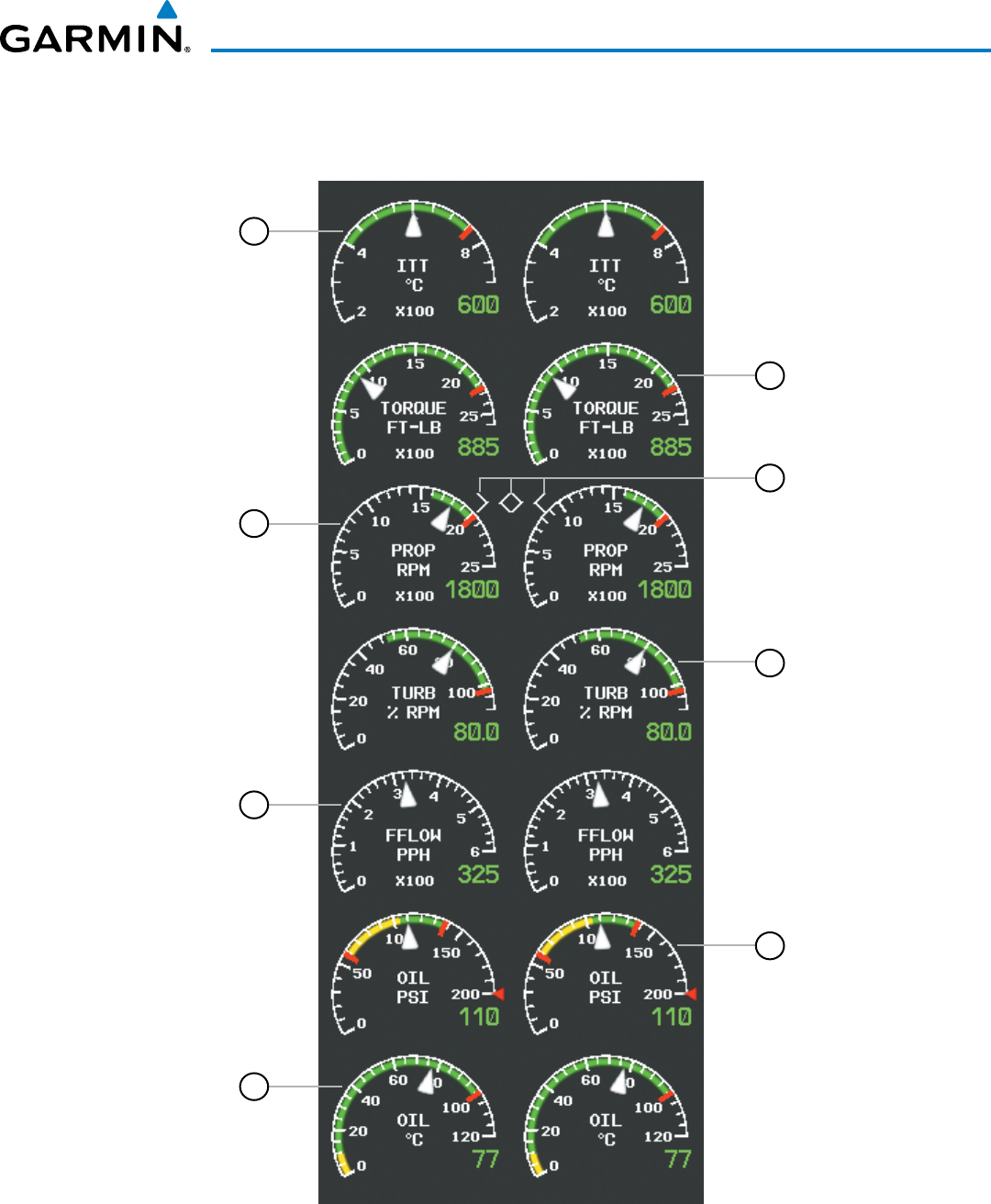
190-00928-04 Rev. A
Garmin G1000 Pilot’s Guide for the Beechcraft 200/B200 Series
97
ENGINE INDICATION SYSTEM
Figure 3-2 EIS Display (Normal Mode)
200/B200 Example Configuration
8
5
4
3
2
1
6
7
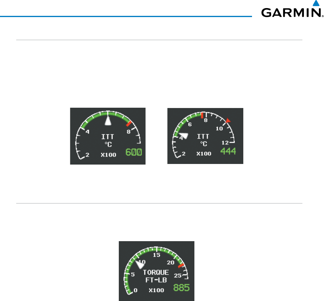
Garmin G1000 Pilot’s Guide for the Beechcraft 200/B200 Series
190-00928-04 Rev. A98
ENGINE INDICATION SYSTEM
INTERSTAGE TURBINE TEMPERATURE
The Interstage Turbine Temperature (ITT) Gauge is displayed at the top of the EIS strip. This gauge differs for
engine start and running conditions. Values between 200 and 1200 degrees Celsius (°C) are shown at engine
start; values change to 200 to 900 °C once the engine has stabilized. A red triangle is displayed at 1000 °C
during engine start to indicate maximum starting ITT. If the ITT remains above 750 °C (red tick mark) for more
than 5 seconds, a warning condition occurs.
Figure 3-3 ITT Gauge
ITT Engine Running ITT Engine Start
TORQUE
The Torque Gauge displays engine power in foot-pounds and is located beneath the ITT gauge. The values
range from 0 FT-LB to 2600 FT-LB If the torque remains above 2230 FT-LB for more than 5 seconds, a warning
condition occurs.
Figure 3-4 Torque Gauge
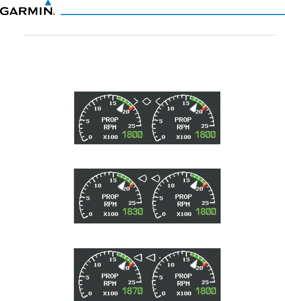
190-00928-04 Rev. A
Garmin G1000 Pilot’s Guide for the Beechcraft 200/B200 Series
99
ENGINE INDICATION SYSTEM
TACHOMETER (RPM)
The Tachometer is located beneath the Torque gauge and displays the propeller speed in revolutions per
minute (RPM) from 0 to 2500. A propeller overspeed is indicated if the propeller speed exceeds the maximum
safe operating speed (red tick mark). The Tachometer is equipped with a propeller sync indicator, which
points towards the higher-speed propeller when propellers are out of sync. The indicator changes linearly
with RPM difference between the left and right propellers. A full diamond is displayed when the propellers are
synchronized and transitions to a full arrowhead when the difference is greater or equal to 50 rpm.
Figure 3-5 Propellers Synchronized
Figure 3-6 Propellers Out of Sync (less than 50 rpm)
Figure 3-7 Propellers Out of Sync
(greater than or equal to 50 rpm)
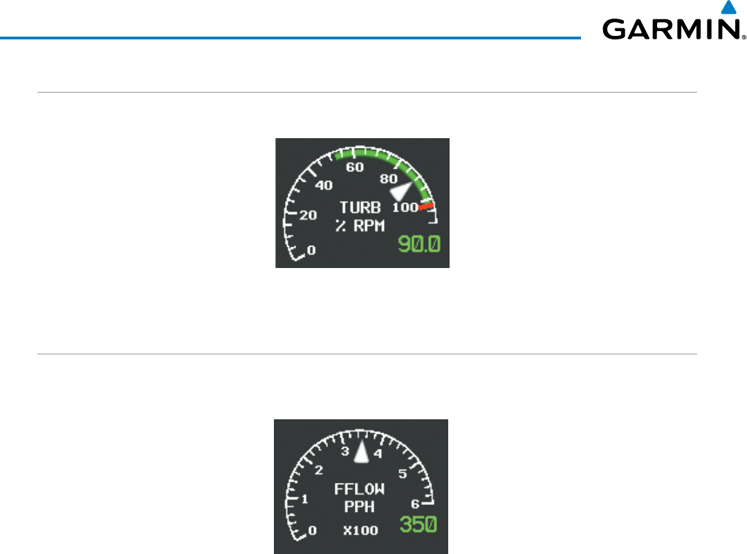
Garmin G1000 Pilot’s Guide for the Beechcraft 200/B200 Series
190-00928-04 Rev. A100
ENGINE INDICATION SYSTEM
TURBINE SPEED
The Turbine Speed Gauge is located beneath the Tachometer. The gauge range is from 0 to 110%.
Figure 3-8 Turbine Speed Gauge
FUEL FLOW
The Fuel Flow Gauge is displayed beneath the Turbine Speed gauge. Fuel Flow is displayed in pounds per
hour (pph) from 0 to 600 pph.
Figure 3-9 Fuel Flow Gauge
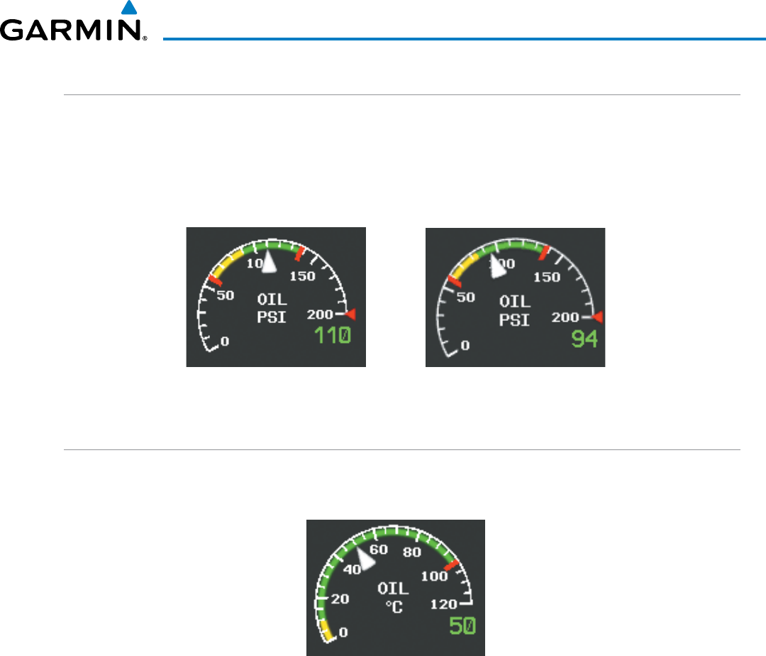
190-00928-04 Rev. A
Garmin G1000 Pilot’s Guide for the Beechcraft 200/B200 Series
101
ENGINE INDICATION SYSTEM
OIL PRESSURE
The Oil Pressure Gauge is located beneath the Fuel Flow gauge. Oil pressure is displayed in pounds per square
inch (psi) from 0 to 200 psi. Safe operating pressure is more than 90 psi and less than 135 psi (varies based on
altitude above FL210 and type of engines installed; refer to the AFM). A red triangle represents the maximum oil
transient pressure at 200 psi.
Figure 3-10 Oil Pressure Gauge
Above FL210
Below FL210
OIL TEMPERATURE
The Oil Temperature Gauge is located beneath the Oil Pressure gauge. Oil temperature is displayed in
degrees Celsius (°C).
Figure 3-11 Oil Temperature Gauge
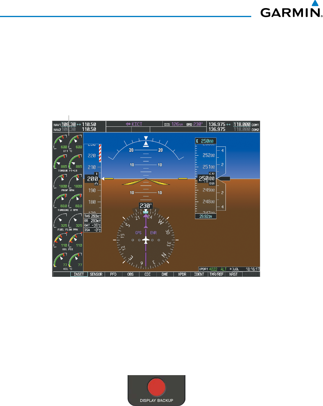
Garmin G1000 Pilot’s Guide for the Beechcraft 200/B200 Series
190-00928-04 Rev. A102
ENGINE INDICATION SYSTEM
3.2 EIS DISPLAY IN REVERSIONARY MODE
PFD1 will revert to reversionary (or backup) mode automatically during an MFD failure in flight. In the event
of PFD1 or PFD2 failure, the Display Backup button must be pressed to enter reversionary mode. Reversionary
mode is a mode of operation in which all important flight information is presented identically on at least one
of the operating displays (see Figure 3-12). Transition to reversionary mode should be straightforward for the
pilot. Flight parameters are presented in the same format as in normal mode (refer to the System Overview for
information about display Reversionary Mode).
Figure 3-12 Reversionary Mode (200/B200)
EIS Display
In the event of display failure, the display modes are as follows:
•
PFD1 failure
– Press the Display Backup button on the left Audio Panel. MFD enters reversionary mode; PFD2
remains in normal mode.
•
MFD failure
– Press the Display Backup buttons on both Audio Panels. PFD1 and PFD2 enter reversionary
mode.
•
PFD2 failure
– Press the Display Backup button on the right Audio Panel. MFD enters reversionary mode;
PFD1 remains in normal mode.
Figure 3-13 Display Backup Button
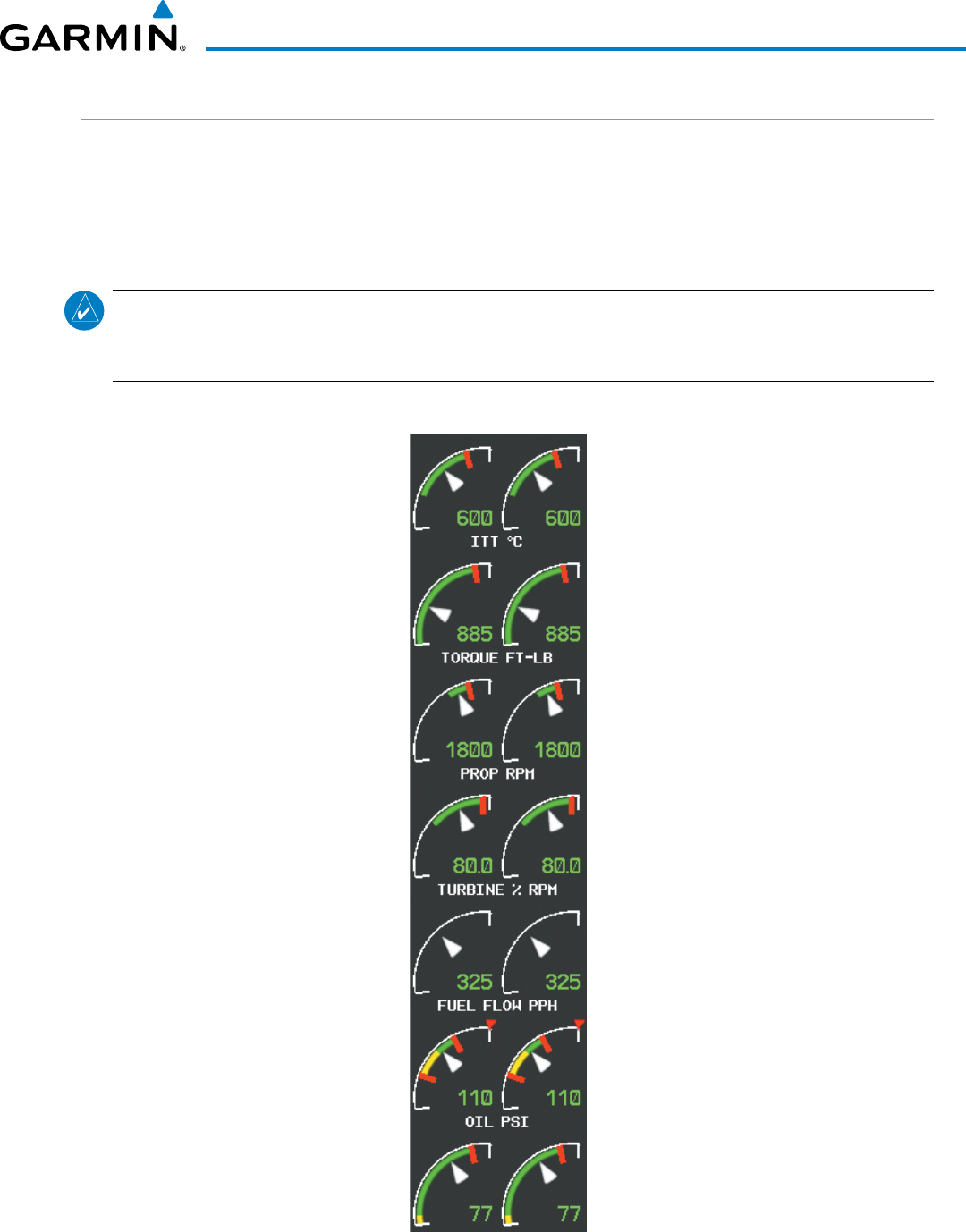
190-00928-04 Rev. A
Garmin G1000 Pilot’s Guide for the Beechcraft 200/B200 Series
103
ENGINE INDICATION SYSTEM
REVERSIONARY DISPLAY
The EIS Reversionary Mode Display gauges have a different shape and share one title (i.e. ITT, TORQUE)
for each pair of gauges. White tick marks are displayed only at the minimum and maximum values. Green
bands on the instrument scales indicate normal ranges of operation; yellow and red bands indicate caution and
warning, respectively. No minor tick marks or numeric labels are displayed. Prop Synchronization information
is not displayed while in Reversionary Mode.
NOTE: The gauges displayed and the values shown in this section are taken from an example Beechcraft
200/B200 configuration. Refer to the Pilot’s Operating Handbook (POH) and FAA Approved Airplane Flight
Manual (AFM) for specific values and operating limitations.
Figure 3-14 EIS Reversionary Mode Display
200/B200 Example Configuration

Garmin G1000 Pilot’s Guide for the Beechcraft 200/B200 Series
190-00928-04 Rev. A104
ENGINE INDICATION SYSTEM
Blank Page

190-00928-04 Rev. A
Garmin G1000 Pilot’s Guide for the Beechcraft 200/B200 Series
105
AUDIO PANEL AND CNS
SECTION 4 AUDIO PANEL AND CNS
4.1 OVERVIEW
The Communication/Navigation/Surveillance (CNS) system includes the Audio Panels, communication radios,
navigation radios, and Mode S transponders. The System Overview Section provides a block diagram description
of the Audio Panels and CNS system interconnection.
CNS operation in the Beechcraft 200/B200 Series is performed by the following Line Replaceable Units
(LRUs):
• Primary Flight Display (PFD) (2)
• Multi Function Display (MFD)
• Integrated Avionics Unit (2)
• Audio Panel (2)
• Mode S Transponder (2)
• Control Unit
The PFD and Control Unit controls are used to tune the communication transceivers and navigation radios.
The two Audio Panels provide the traditional audio selector functions of microphone and receiver audio
selection. Each Audio Panel includes a two position intercom system (ICS) between the pilot and copilot, a
marker beacon system, and a COM clearance recorder. Ambient noise from the aircraft radios is reduced by a
feature called Master Avionics Squelch (MASQ). When no audio is detected, MASQ processing further reduces
the amount of background noise from the radios.
The Mode S Transponders are controlled with softkeys and the FMS Knobs. The Transponder Data Box is
located to the left of the System Time Box. The data box displays the selected transponder, the active four-digit
code, mode, and a reply status (Figure 4-1).
AUDIO PANEL VOLUME CONTROL
Adjusting the master volume control affects all radio audio volume and airframe type warnings that are heard
in the headsets (not the speaker) for the pilot or copilot side Audio Panel. Radio adjustments made on the PFD
controls to compensate for the master volume change on the Audio Panel also affect the radio levels for the other
pilot. Independent radio volume adjustments made using the Audio Panel Master Volume controls affect only
the audio heard in the corresponding crew position headset.
Radio volume adjustments may be overridden by each crew position independently using the master volume
control on the Audio Panel for the respective crew position. In addition, the master volume control for each
Audio Panel affects all other system audio output to its designated crew position headset much like volume
adjustments found on many aviation headsets.
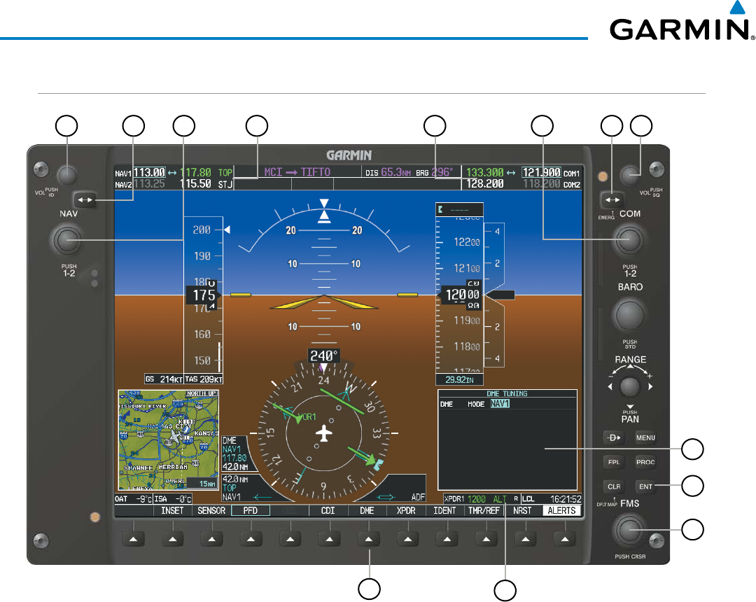
190-00928-04 Rev. A
Garmin G1000 Pilot’s Guide for the Beechcraft 200/B200 Series
106
AUDIO PANEL AND CNS
PFD CONTROLS AND FREQUENCY DISPLAY
Figure 4-1 PFD Controls, NAV/COM Frequency Tuning Boxes, and DME Tuning Window
12
21 68
7
345
9
10
11
13

190-00928-04 Rev. A
Garmin G1000 Pilot’s Guide for the Beechcraft 200/B200 Series
107
AUDIO PANEL AND CNS
1
NAV VOL/ID Knob
– Controls NAV audio volume level. Press to turn the Morse code identifier audio on
and off. Volume level is shown in the NAV frequency field as a percentage.
2
NAV Frequency Transfer Key
– Transfers the standby and active NAV frequencies.
3
NAV Knob
– Tunes the standby frequencies for the NAV receiver (large knob for MHz; small knob for kHz).
Press to move the frequency selected for tuning (light blue numbers) and the Frequency Transfer Arrow
between NAV1 and NAV2.
4
NAV Frequency Box
– Displays NAV standby and active frequency fields, volume, and station ID. The
frequency of the NAV radio selected for navigation is displayed in green.
5
COM Frequency Box
– Displays COM standby and active frequency fields and volume. The selected COM
transceiver frequency is displayed in green.
6
COM Knob
– Tunes the standby frequencies for the COM transceiver (large knob for MHz; small knob for
kHz). Press to move the frequency selected for tuning (light blue numbers) and the Frequency Transfer
Arrow between COM1 and COM2.
7
COM Frequency Transfer Key
– Transfers the standby and active COM frequencies. Press and hold this key
for two seconds to tune the emergency frequency (121.500 MHz) automatically into the active frequency
field.
8
COM
VOL/SQ Knob
– Controls COM audio volume level. Press to turn the COM automatic squelch on
and off. Volume level is shown in the COM frequency field as a percentage.
9
DME Tuning Window
– Displays DME frequency pairing mode. Display by selecting the DME Softkey.
10
ENT Key
– Validates or confirms DME pairing mode and Auto-tune selection.
11
FMS Knob
– Flight Management System Knob, used to enter transponder codes, select DME modes, and
Auto-tune entries when DME Tuning Window or NRST Window is present. Press the FMS Knob to turn
the selection cursor on and off. The large knob moves the cursor in the window. The small knob selects
individual characters for the highlighted cursor location.
12
Transponder Data Box
– Indicates the selected transponder code, operating mode, reply, and ident status
for the applicable transponder.
13
DME Softkey
– Displays the DME Tuning Window.
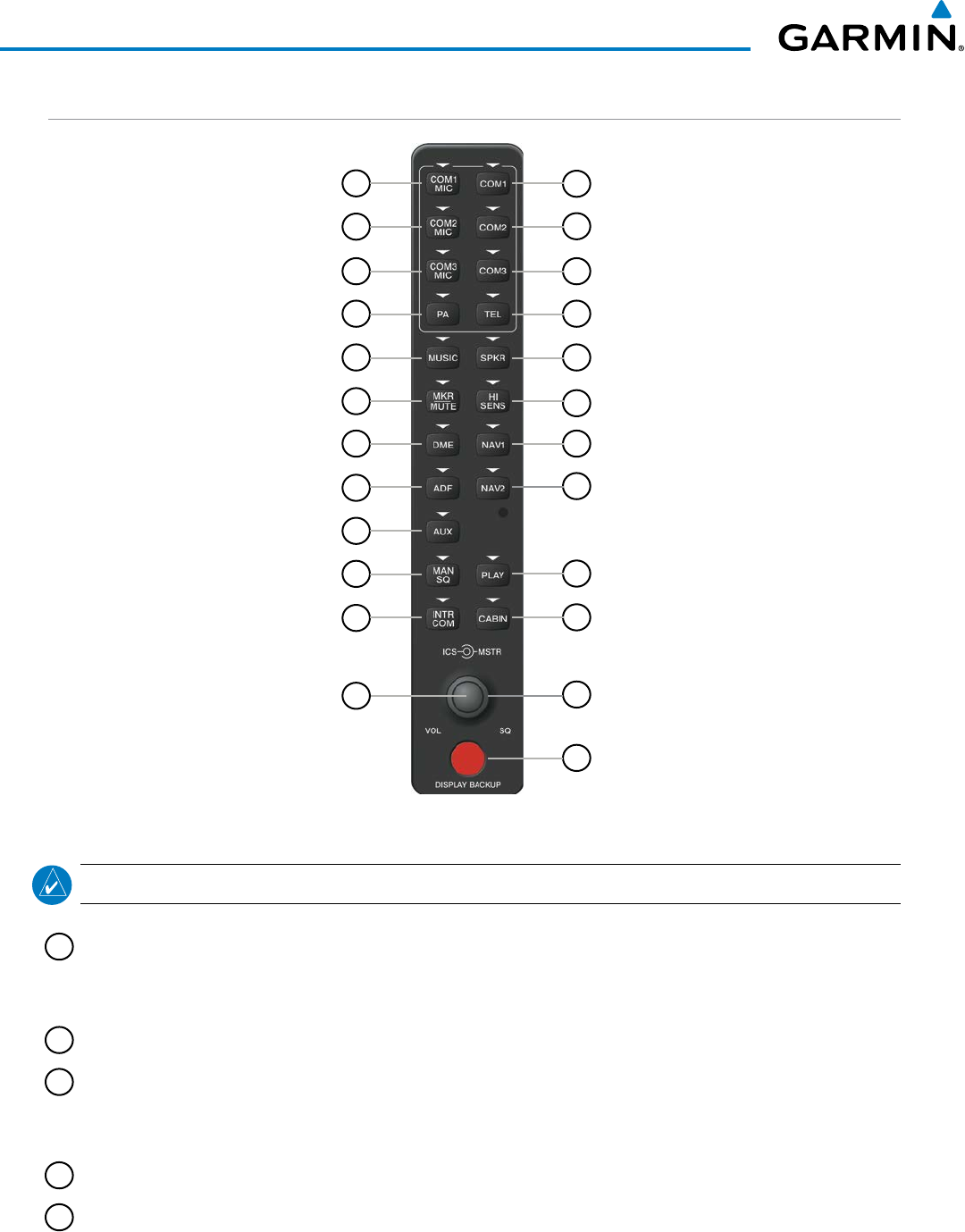
190-00928-04 Rev. A
Garmin G1000 Pilot’s Guide for the Beechcraft 200/B200 Series
108
AUDIO PANEL AND CNS
AUDIO PANEL CONTROLS
Figure 4-2 Audio Panel Controls
17
18
15
13
11
9
20
7
5
3
1
14
2
16
4
6
8
10
12
22
24
23
21
19
NOTE: When a key is selected, a triangular annunciator above the key is illuminated.
1
COM1 MIC
– Selects the #1 transmitter for transmitting. COM1 receive is simultaneously selected when
this key is pressed allowing received audio from the #1 COM receiver to be heard. COM2 receive can be
added by pressing the COM2 Key.
2
COM1
– When selected, audio from the #1 COM receiver can be heard.
3
COM2 MIC
– Selects the #2 transmitter for transmitting. COM2 receive is simultaneously selected when
this key is pressed allowing received audio from the #2 COM receiver to be heard. COM1 receive can be
added by pressing the COM1 Key.
4
COM2
– When selected, audio from the #2 COM receiver can be heard.
5
COM3 MIC
– Reserved for optional COM radio.

190-00928-04 Rev. A
Garmin G1000 Pilot’s Guide for the Beechcraft 200/B200 Series
109
AUDIO PANEL AND CNS
6
COM3
– Reserved for optional COM radio.
7
PA
– Selects the passenger address system. The selected COM transmitter is deselected when the PA Key
is pressed.
8
TEL
– When selected, activates the SATCOM transceiver enabling telephone audio and MIC.
9
MUSIC
– Toggles the Music 1 input on or off. Pressing and holding toggles music muting on or off.
10
SPKR
– Selects and deselects the on-side flight deck speaker. COM and NAV receiver audio can be heard
on the speaker.
11
MKR/MUTE
– Selects marker beacon receiver audio. Mutes the currently received marker beacon receiver
audio. Unmutes automatically when new marker beacon audio is received.
12
HI SENS
– Press to increase marker beacon receiver sensitivity. Press again to return to low sensitivity.
13
DME
– Turns optional DME audio on or off.
14
NAV1
– When selected, audio from the #1 NAV receiver can be heard.
15
ADF
– Turns optional ADF receiver audio on or off.
16
NAV2
– When selected, audio from the #2 NAV receiver can be heard.
17
AUX
– Not used in Beechcraft 200/B200 Series aircraft.
18
MAN SQ
– Enables manual squelch for the intercom. When the intercom is active, press the ICS Knob to
illuminate SQ. Turn the ICS Knob to adjust squelch.
19
PLAY
– Press once to play the last recorded COM audio. Press again to stop playing. Press twice within 0.5
second while audio is playing and the previous block of recorded audio will be played. Each subsequent
two presses within 0.5 second plays each previously recorded block.
20
INTR COM
– Selects and deselects the pilot/copilot intercom on both Audio Panels.
21
CABIN
– Initiates intercom communications with passengers in the cabin.
22
ICS Knob
– Turn to adjust intercom volume or squelch. Press to switch between volume and squelch
control as indicated by illumination of VOL or SQ. The MAN SQ Key must be selected to allow squelch
adjustment.
23
MSTR Knob
– The Master Volume Control adjusts volume for the blended NAV, COM, intercom audio,
and alert warnings.
24
DISPLAY BACKUP Button
– Manually selects PFD/MFD Reversionary Mode.
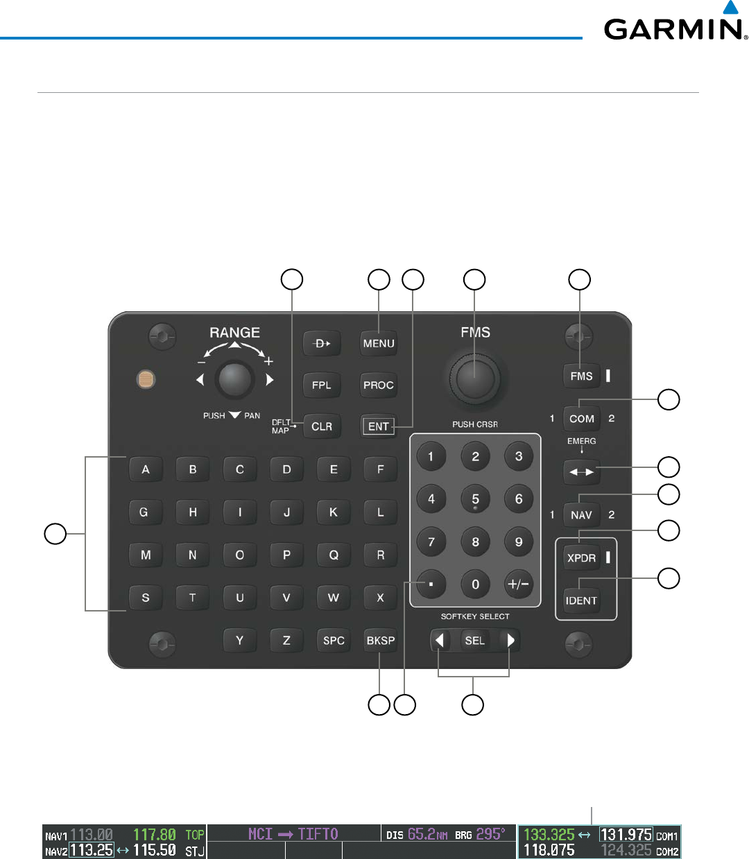
190-00928-04 Rev. A
Garmin G1000 Pilot’s Guide for the Beechcraft 200/B200 Series
110
AUDIO PANEL AND CNS
CONTROL UNIT
The Control Unit is a pedestal-mounted interface allowing MFD operation, data entry, COM and NAV tuning,
and transponder control. Many procedures can be performed using the Control Unit rather than the display
bezel controls. Annunciators beside the FMS, XPDR, COM, and NAV keys illuminate when their respective
control modes are selected. The unit is in FMS control mode by default on system power-up.
The appropriate frequency box on the selected display is outlined by a light blue selection box, which flashes
for a few seconds to indicate control unit activity. Selection of a different display control or radio tuning mode
results in cancelation of the previous radio tuning mode.
Figure 4-3 Control Unit
3
1
14
2
13 11
4
12
5
10
6
7
8
9
Figure 4-4 Frequency Tuning with the Control Unit
Tuning Selection
Box

190-00928-04 Rev. A
Garmin G1000 Pilot’s Guide for the Beechcraft 200/B200 Series
111
AUDIO PANEL AND CNS
1
CLR Key – Erases information, cancels entries, or removes menus. Press and hold to activate the Navigation
Map Page on the MFD
2
MENU Key – Displays a list of options for accessing additional features or making setting changes.
3
ENT Key – Validates or confirms a menu selection or data entry.
4
FMS Knob – Flight Management System Knob. This knob provides tuning capability for the COM and
NAV radios when the appropriate COM or NAV key is pressed. When the XPDR Key is pressed, the
transponder code may be entered using the FMS Knob. The large knob moves the cursor in the window.
The small knob selects individual characters for the highlighted cursor location.
5
FMS
Key – Sets the FMS Knob to control FMS functions on the MFD. When pressed, an annunciator next
to the key illuminates indicating adjustment of the FMS Knob will now affect FMS functions.
6
COM Key – Sets the FMS Knob to control tuning of the COM radios. The first press will select COM1,
as indicated by an illuminated “1” to the left of the key. Press again to select COM2. This is annunciated
with a “2” to the right of the key. Each subsequent press of the COM Key will switch between COM1 and
COM2. Use the FMS Knob to tune the selected COM The COM Tuning Selection Box is outlined with a
light blue line when the COM frequency is active on the control unit (Figure 4-4).
7
Frequency Transfer Key (EMERG) – Transfers the standby and active COM or NAV frequencies. Press
and hold for two seconds to tune the emergency frequency (121.500 MHz) automatically into the COM
active frequency field.
8
NAV Key – Sets the FMS Knob to control tuning of the NAV radios. The first press will select NAV1, as
indicated by an illuminated “1” to the left of the key. Press again to select NAV2. This is annunciated with
a “2” to the right of the key. Each subsequent press of the N AV Key will switch between NAV1 and NAV2.
Use the FMS Knob to tune the selected NAV. The NAV Tuning Selection Box is outlined with a light blue
line when the NAV frequency is active on the control unit.
9
XPDR Key
– Sets the FMS Knob to enter transponder codes. When pressed, an annunciator next to the
key illuminates indicating the FMS Knob can now be used for transponder code entry. Transponder code
entry can be performed with either the number keypad or FMS Knob.
10
IDENT
Key – Press to activate the IDENT function of the transponder. When the
IDENT
Key is pressed,
a green
IDNT
indication is displayed in the mode field of the Transponder Data Box for 18 seconds.
11
SEL Key
– The center of this key activates the selected MFD softkey, while the right and left arrows move
the softkey selection box to the right and left, respectively.
12
Decimal Key – Enters a decimal point.
13
BKSP Key – Moves cursor back one character space and removes last character entered.
14
Alphanumeric Keys – Allows data entry (rather than using the FMS Knob to select characters/
numbers).
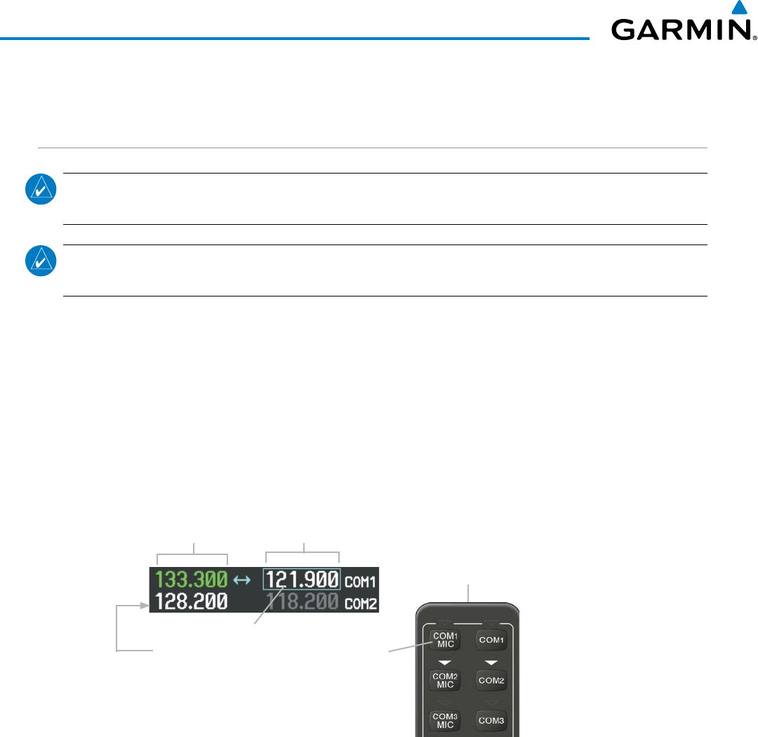
190-00928-04 Rev. A
Garmin G1000 Pilot’s Guide for the Beechcraft 200/B200 Series
112
AUDIO PANEL AND CNS
4.2 COM OPERATION
COM TRANSCEIVER SELECTION AND ACTIVATION
NOTE: During PA Mode, the COM MIC Annunciator is extinguished and the COM active frequency color
changes to white, indicating that neither COM transmitter is active.
NOTE: When turning on the G1000 for use, the system remembers the last frequencies used and the active
COM transceiver state prior to shutdown.
The COM Frequency Box is composed of four fields; the two active frequencies are on the left side and the
two standby frequencies are on the right. The COM transceiver is selected for transmitting by pressing the
COM MIC
Keys on the Audio Panel. During reception of audio from the COM radio selected for transmission,
audio from the other COM radio is muted.
An active COM frequency displayed in green indicates that the COM transceiver is selected on the Audio
Panel (
COM1 MIC
or
COM2 MIC
Key). Both active COM frequencies appearing in white indicate that no COM
radio is selected for transmitting (PA Key is selected on the Audio Panel).
Frequencies in the standby field are displayed in either white or gray. The standby frequency selected for
tuning is white and outlined in cyan. The other standby frequency is gray.
Active
Fields Standby
Fields
Selected for Tuning
COM1 Radio is Selected on the Audio Panel
Figure 4-5 Selecting a COM Radio for Transmit
Top Section of
the Audio Panel
COM3 is reserved for an optional COM radio.
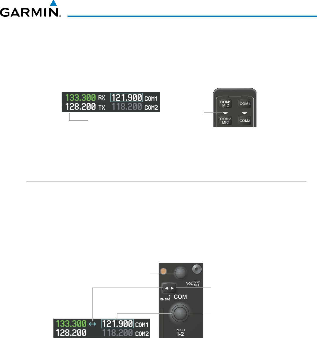
190-00928-04 Rev. A
Garmin G1000 Pilot’s Guide for the Beechcraft 200/B200 Series
113
AUDIO PANEL AND CNS
TRANSMIT/RECEIVE INDICATIONS
During COM transmission, a white TX appears by the active COM frequency. On the Audio Panel, when
the active COM is transmitting, the active transceiver
COM MIC
Key Annunciator flashes approximately once
per second.
During COM signal reception, a white RX appears by the active COM frequency.
Figure 4-6 COM Radio Transmit and Receive Indications
Annunciator
Flashes During
Transmission
Transmit and
Receive Indicators
When the same COM radio is selected on both Audio Panels, the pilot has transmit priority on COM1, the
copilot has transmit priority on COM2.
COM TRANSCEIVER MANUAL TUNING
The COM frequency controls and frequency boxes are on the right side of each PFD.
Manually tuning a COM frequency:
1) Turn the COM Knob to tune the desired frequency (large knob for MHz; small knob for kHz).
2) Press the
Frequency Transfer
Key to transfer the frequency to the active field.
3) Adjust the volume level with the COM VOL/SQ Knob
.
4) Press the COM VOL/SQ Knob to turn automatic squelch on and off.
Turn the
VOL/SQ
Knob to adjust
volume. Press the Knob to Turn
Automatic Squelch On or Off Press the
Frequency Transfer
Key to Transfer COM
Frequencies Between Active
and Standby Frequency
Turn the
COM
Knob
to Tune the Selected
Frequency
Figure 4-7 COM Frequency Tuning
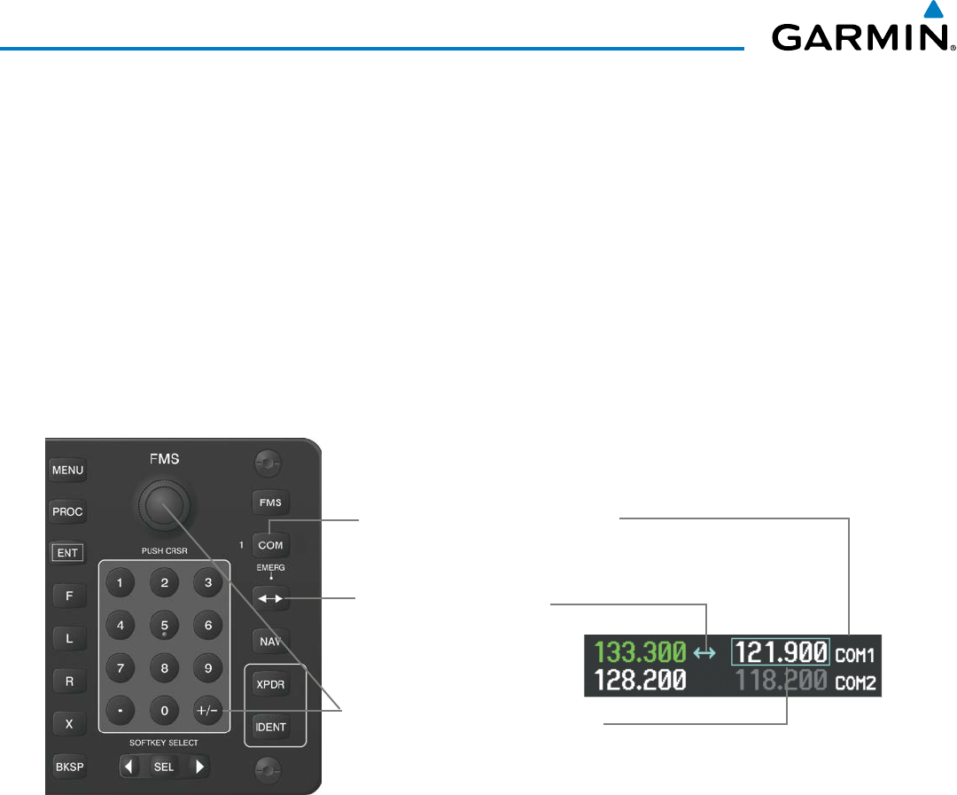
190-00928-04 Rev. A
Garmin G1000 Pilot’s Guide for the Beechcraft 200/B200 Series
114
AUDIO PANEL AND CNS
Manual COM frequency tuning from the Control Unit
1) Press the COM Key to enable the FMS Knob for COM tuning. The COM Tuning Selection Box is shown.
2) Press the COM Key again, if needed, to select the desired COM radio (1 or 2).
3) Turn the FMS Knob to tune the desired frequency in the COM Tuning Box (large knob for MHz; small knob for
kHz).
Or:
Press the numeric keys on the keypad to enter a Frequency.
4) Press the
Frequency Transfer
Key to transfer the frequency to the active field.
If an error is made during frequency entry with the numeric keypad, pressing the BKSP Key moves the cursor
back one space. If an incorrect frequency is entered, reenter the correct one using the same procedure.
Figure 4-8 Frequency Tuning from the Control Unit
Second, Turn the
FMS
Knob or Press
the Numeric Keys to Enter a Frequency
into the COM Standby Frequency Box
Third, Press the
Frequency
Transfer
Key to Move the
Frequency to the Active Field.
First, Press the
COM
Key to activate COM
tuning from the
FMS
Knob or Numeric
Keypad
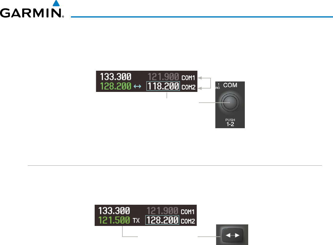
190-00928-04 Rev. A
Garmin G1000 Pilot’s Guide for the Beechcraft 200/B200 Series
115
AUDIO PANEL AND CNS
SELECTING THE RADIO TO BE TUNED
Press the small COM Knob to move the COM Tuning Box and the Frequency Transfer Arrow between the
COM radios.
Figure 4-9 Switching COM Tuning Boxes
Press the
COM
Knob to Switch
the Tuning Selection From One
COM Radio to the Other
QUICK-TUNING AND ACTIVATING 121.500 MHZ
Pressing and holding the COM
Frequency Transfer
Key for two seconds automatically loads the emergency
COM frequency (121.500 MHz) in the active field of the COM radio selected for tuning (the one with the
transfer arrow). In the example shown, pressing the Audio Panel COM2 MIC Key activates the transceiver.
Figure 4-10 Quickly Tuning 121.500 MHz
Press for Two Seconds to
Load 121.500 MHz
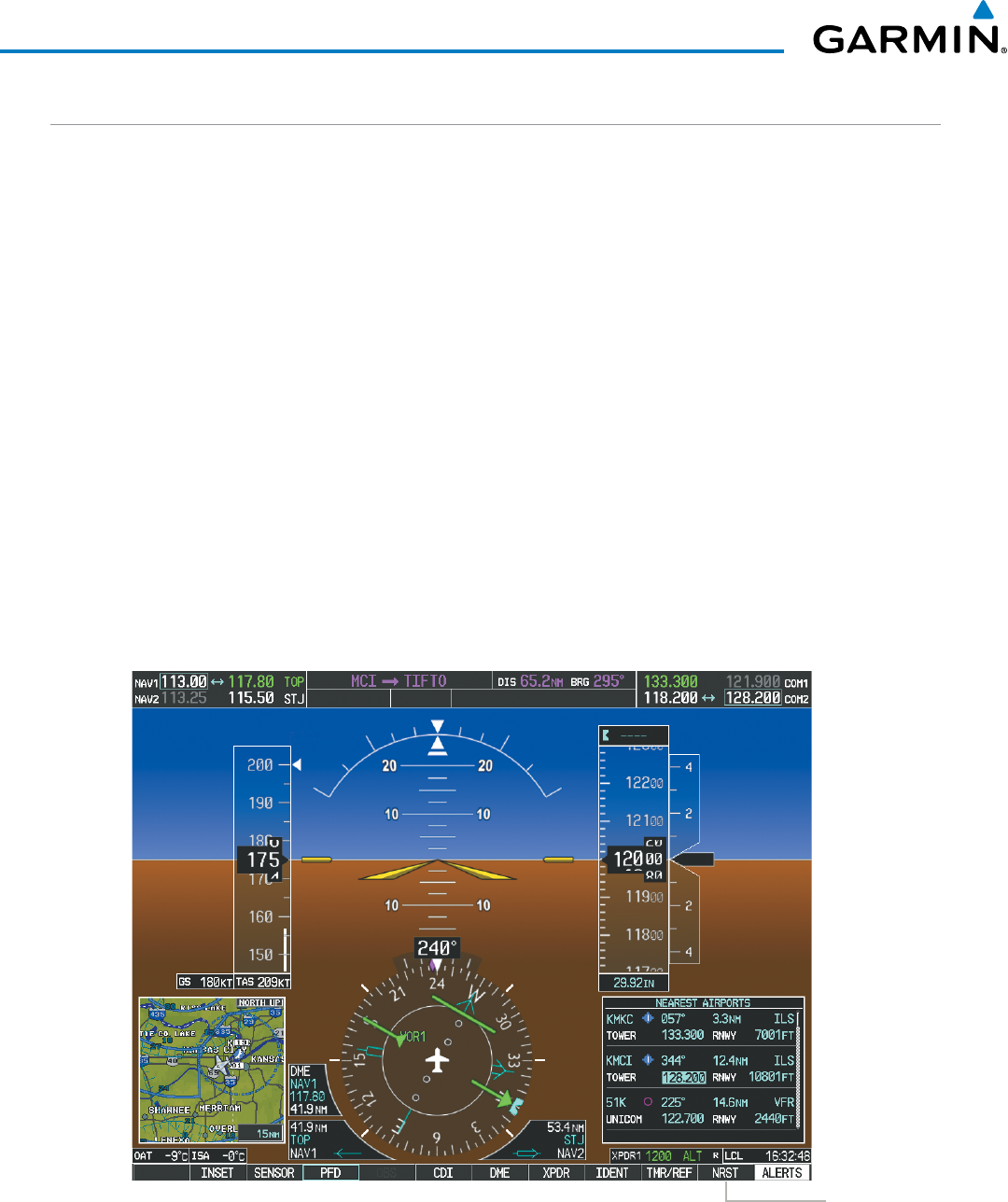
190-00928-04 Rev. A
Garmin G1000 Pilot’s Guide for the Beechcraft 200/B200 Series
116
AUDIO PANEL AND CNS
AUTO-TUNING THE COM FREQUENCY
COM frequencies can be automatically tuned from the following:
• Nearest Airports Window (PFD)
• WPT – Airport Information Page
• NRST – Nearest Airports Page
• NRST – Nearest Frequencies Page (ARTCC, FSS, WX)
• NRST – Nearest Airspaces Page
AUTO-TUNING FROM THE PFD
COM frequencies for the nearest airports can be automatically tuned from the Nearest Airports Window on
the PFD. When the desired frequency is entered, it becomes a standby frequency. Pressing the
Frequency
Transfer
Key places this frequency into the COM Active Frequency Field.
Auto-tuning a COM frequency for a nearby airport from the PFD:
1) Select the
NRST
Softkey on the PFD to open the Nearest Airports Window. A list of 25 nearest airport identifiers
and COM frequencies is displayed.
2) Turn the
FMS
Knob to scroll through the list and highlight the desired COM frequency.
3) Press the
ENT
Key to load the COM frequency into the COM Standby Frequency Field.
4) Press the Frequency Transfer Key to transfer the frequency to the COM Active Frequency Field.
Figure 4-11 Nearest Airports Window (PFD)
Select the
NRST
Softkey to Open
the Nearest
Airports Window
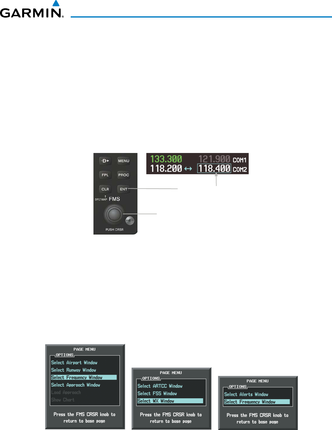
190-00928-04 Rev. A
Garmin G1000 Pilot’s Guide for the Beechcraft 200/B200 Series
117
AUDIO PANEL AND CNS
AUTO-TUNING FROM THE MFD
Frequencies can be automatically loaded into the COM Frequency Box from pages in the NRST or WPT
page group by highlighting the frequency and pressing the ENT Key (Figures 4-12, 4-13, and 4-14).
Auto-tuning a COM frequency from the WPT and NRST Pages:
1) From any page that the COM frequency can be auto-tuned, activate the cursor by pressing the FMS Knob or
selecting the appropriate softkey.
2) Turn the FMS Knob to place the cursor on the desired COM frequency (Figure 4-12).
3) Press the ENT Key to load the COM frequency into the standby field of the selected COM radio.
4) Press the Frequency Transfer Key on either PFD to transfer the frequency to the COM Active Frequency
Field.
Figure 4-12 Frequency Auto-Tuning from the MFD
Press the
ENT
Key to Load a
Highlighted Frequency into the
COM Standby Frequency Box.
Turn the
FMS
Knob to Scroll Through a
List of Frequencies.
Or:
1) Press the MENU Key to display the page menu (Figure 4-13).
2) Turn the large FMS Knob to scroll through the menu options.
3) Press the ENT Key to place the cursor on the desired selection.
4) Scroll through the frequency selections with the FMS Knob or the ENT Key.
5) Press the ENT Key to load the COM frequency into the standby field of the selected COM radio.
6) Press the Frequency Transfer Key to transfer the frequency to the COM Active Frequency Field.
Figure 4-13 Nearest Pages Menus
Nearest Airspaces Menu
Nearest Airports Menu Nearest Frequencies Menu
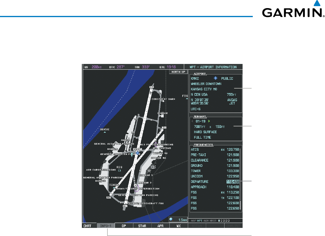
190-00928-04 Rev. A
Garmin G1000 Pilot’s Guide for the Beechcraft 200/B200 Series
118
AUDIO PANEL AND CNS
On the WPT - Airport Information Page, the cursor can be placed on the frequency field by pressing the
FMS Knob and scrolling through the list. The frequency is transferred to the COM Standby Field with the
ENT Key.
Press
ENT
Key to
load frequency
into PFD1 COM
Standby Field.
Cursor then
advances to the
next frequency.
Select
INFO-1
Softkey for
AIRPORT,
RUNWAYS, and
FREQUENCIES
Windows
Selected Airport
Identifier and
Information
Runway
Information
Figure 4-14 WPT – Airport Information Page
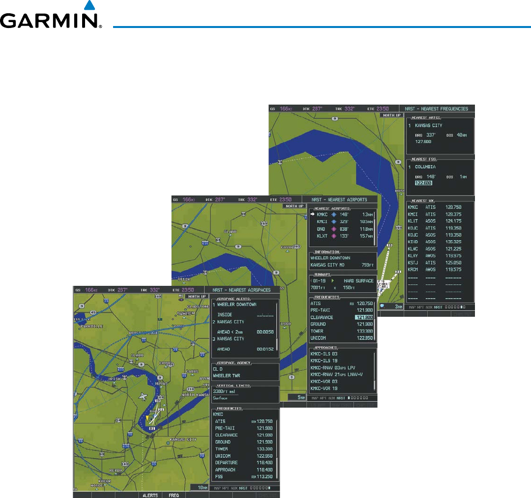
190-00928-04 Rev. A
Garmin G1000 Pilot’s Guide for the Beechcraft 200/B200 Series
119
AUDIO PANEL AND CNS
COM frequencies can also be auto-tuned from the NRST – Nearest Airspaces, NRST – Nearest Frequencies,
and NRST – Nearest Airports Pages on the MFD in a similar manner using the appropriate softkeys or MENU
Key, the FMS Knob, and the ENT Key.
Figure 4-15 NRST – Nearest Airspaces, NRST – Nearest Airports, and NRST – Nearest Frequencies Pages
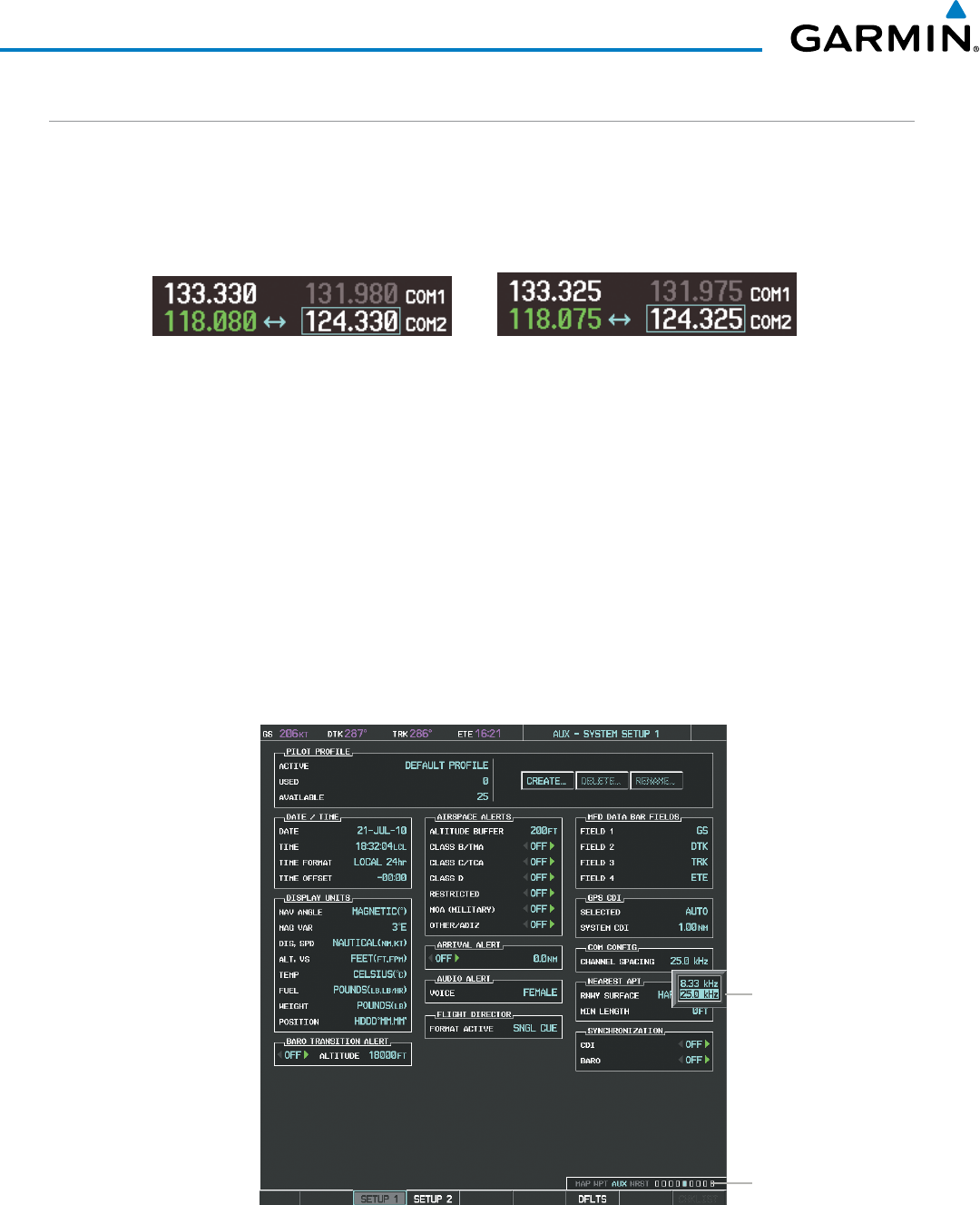
190-00928-04 Rev. A
Garmin G1000 Pilot’s Guide for the Beechcraft 200/B200 Series
120
AUDIO PANEL AND CNS
FREQUENCY SPACING
The G1000 COM radios can tune either 25-kHz spacing (118.000 to 136.975 MHz) or 8.33-kHz spacing
(118.000 to 136.990 MHz) for 760-channel or 3040-channel configuration. When 8.33-kHz channel spacing
is selected, all of the 25-kHz channel spacing frequencies are also available in the complete 3040-channel list.
COM channel spacing is set on the System Setup 1 Page of the AUX Page Group.
Figure 4-16 COM Channel Spacing
25-kHz Channel
Spacing
8.33-kHz Channel
Spacing
Changing COM frequency channel spacing:
1) Select the AUX – System Setup 1 Page.
2) Press the FMS Knob to activate the flashing cursor.
3) Turn the large FMS Knob to highlight the Channel Spacing Field in the COM Configuration Box.
4) Turn the small FMS Knob to select the desired channel spacing.
5) Press the ENT Key to complete the channel spacing selection.
While the COM CONFIG Window is selected, the G1000 softkeys are blank.
Figure 4-17 AUX – System Setup 1 Page
Select 8.33-kHz
or 25.0-kHz
COM Frequency
Channel Spacing
AUX - SYSTEM
SETUP-1 PAGE
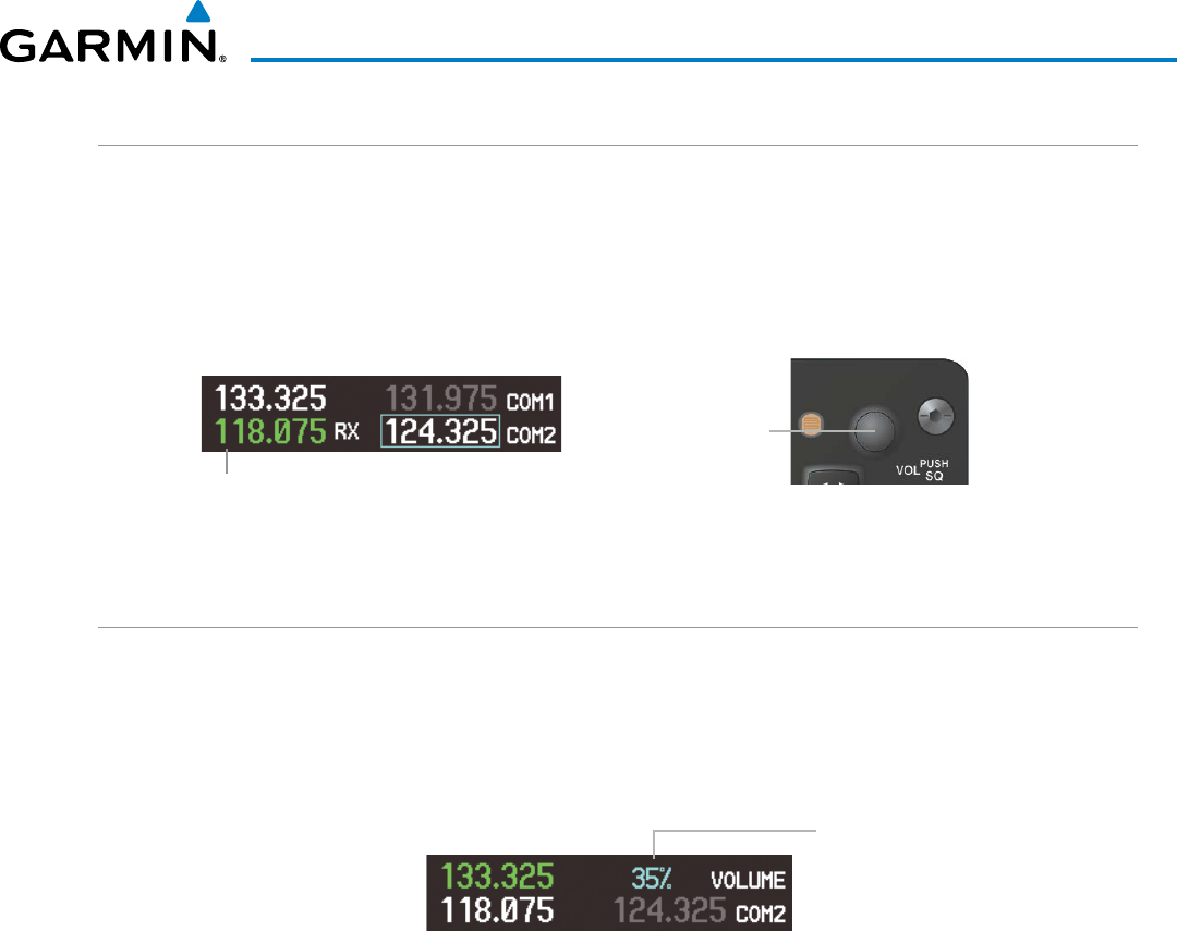
190-00928-04 Rev. A
Garmin G1000 Pilot’s Guide for the Beechcraft 200/B200 Series
121
AUDIO PANEL AND CNS
AUTOMATIC SQUELCH
Automatic Squelch quiets unwanted static noise when no radio transmission is received, while still providing
good sensitivity to weak COM signals. To disable Automatic Squelch, press the
VOL/SQ
Knob. When Automatic
Squelch is disabled, COM audio reception is always on. Continuous static noise is heard over the headsets and
speaker, if selected. Pressing the
VOL/SQ
Knob again enables Automatic Squelch.
When Automatic Squelch is disabled, a white RX appears next to the COM frequency.
Figure 4-18 Overriding Automatic Squelch
Manual Squelch
Indication
Press the COM
VOL/
SQ
Knob to turn off
Automatic Squelch.
Press again to restore
Automatic Squelch.
VOLUME
COM radio volume level can be adjusted from 0 to 100% using the
VOL/SQ
Knob. Turning the knob
clockwise increases volume, turning the knob counterclockwise decreases volume. When adjusting volume,
the level is displayed in place of the standby frequencies. Volume level indication remains for two seconds after
the change.
Figure 4-19 COM Volume Level
COM Volume
Level Remains
for Two Seconds
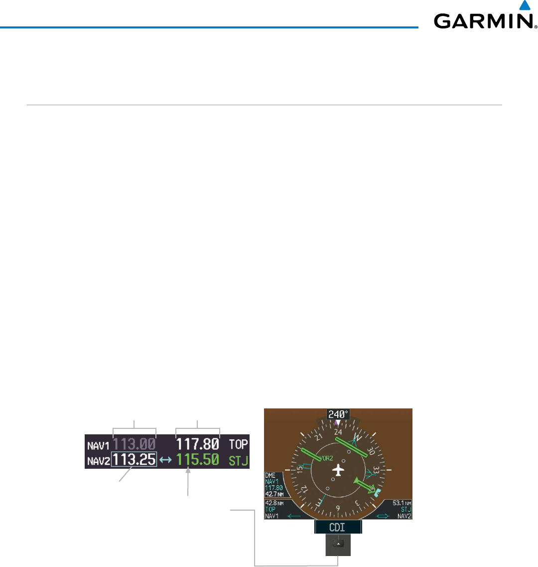
190-00928-04 Rev. A
Garmin G1000 Pilot’s Guide for the Beechcraft 200/B200 Series
122
AUDIO PANEL AND CNS
4.3 NAV OPERATION
NAV RADIO SELECTION AND ACTIVATION
The NAV Frequency Box is composed of four fields; two standby fields and two active fields. The active
frequencies are on the right side and the standby frequencies are on the left.
A NAV radio is selected for navigation by selecting the
CDI
Softkey located on the PFD. The active NAV
frequency selected for navigation is displayed in green. Selecting the
CDI
Softkey once selects NAV1 as the
navigation radio. Selecting the
CDI
Softkey a second time selects NAV2 as the navigation radio. Selecting the
CDI
Softkey a third time activates GPS mode. Selecting the
CDI
Softkey again cycles back to NAV1.
While cycling through the
CDI
Softkey selections, the selected NAV standby frequency is selected for tuning,
the Frequency Transfer Arrow is placed in the selected NAV Frequency Field, and the active NAV frequency
color changes to green.
The three navigation modes that can be cycled through are:
• VOR1 (or LOC1) – If NAV1 is selected, a green single line arrow (not shown) labeled either VOR1 or LOC1
is displayed on the HSI and the active NAV1 frequency is displayed in green.
• VOR2 (or LOC2) – If NAV2 is selected, a green double line arrow (shown) labeled either VOR2 or LOC2 is
displayed on the HSI and the active NAV2 frequency is displayed in green.
• GPS – If GPS Mode is selected, a magenta single line arrow (not shown) appears on the HSI and neither NAV
radio is selected. Both active NAV frequencies are then displayed in white and the previously selected NAV
standby frequency remains selected for tuning.
Figure 4-20 Selecting a NAV Radio for Navigation
Active
Fields
Standby
Fields
Selected for
Tuning The NAV Radio is
Selected by Selecting
the
CDI
Softkey
See the Flight Instruments Section for selecting the DME and Bearing Information windows and using VOR
or ADF as the source for the bearing pointer.
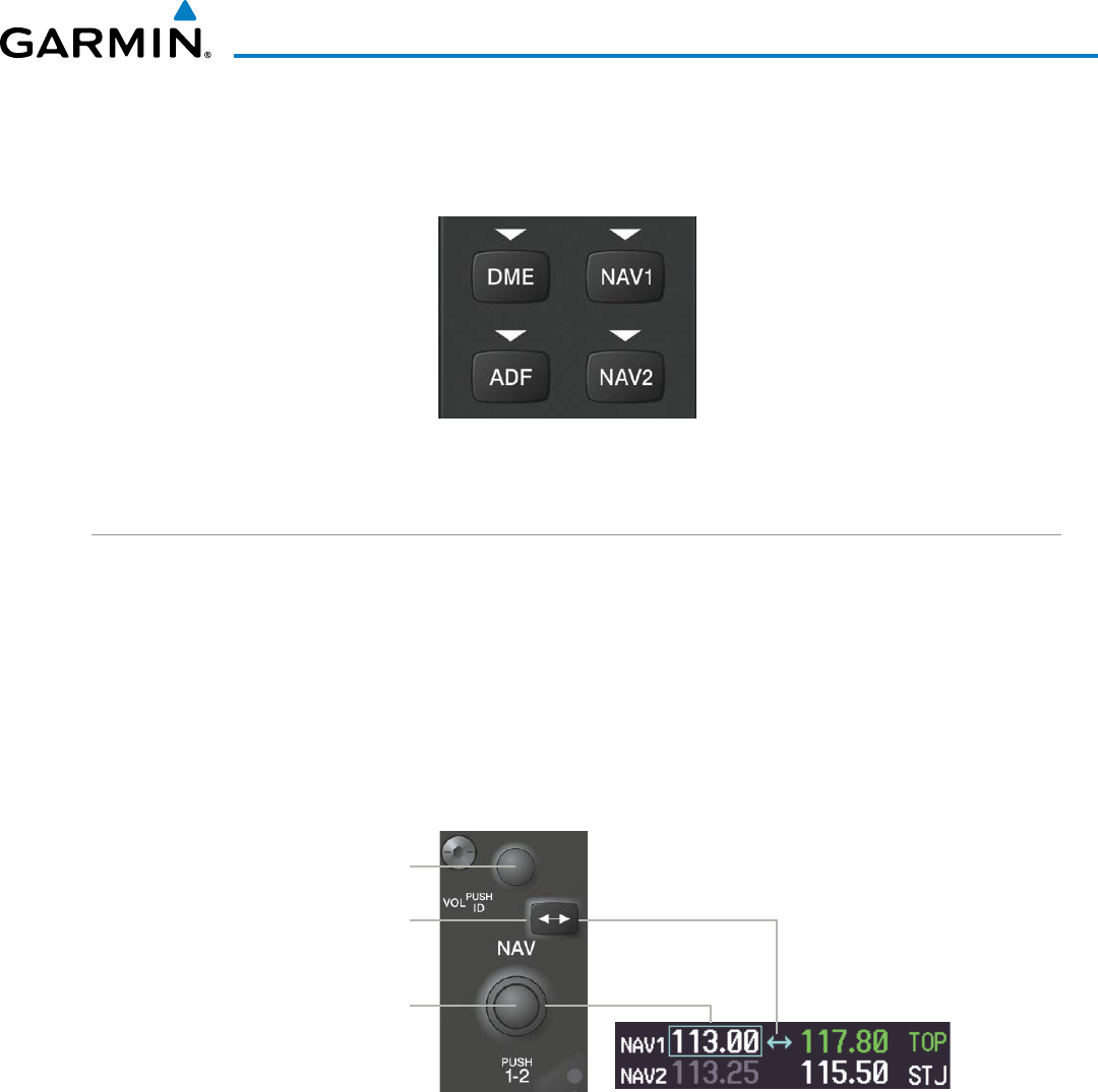
190-00928-04 Rev. A
Garmin G1000 Pilot’s Guide for the Beechcraft 200/B200 Series
123
AUDIO PANEL AND CNS
NAV radios are selected for listening by pressing the corresponding keys on the Audio Panel.
Pressing the
NAV1, NAV2, ADF, or DME Key selects and deselects the navigation radio source. Selected audio can be heard over
the headset and the speakers (if selected). All radios can be selected individually or simultaneously.
Figure 4-21 Selecting a NAV Radio Receiver
NAV RECEIVER MANUAL TUNING
The NAV frequency controls and frequency boxes are on the left side of the PFDs.
Manually tuning a NAV frequency:
1) Turn the
NAV
Knob to tune the desired frequency in the NAV Tuning Box.
2) Press the
Frequency Transfer
Key to transfer the frequency to the NAV Active Frequency Field.
3) Adjust the volume level with the NAV VOL/ID Knob
.
4) Press the NAV VOL/ID Knob to turn the Morse code identifier audio on and off.
Figure 4-22 NAV Frequency Tuning
Press the
Frequency Transfer
Key to
Transfer NAV Frequencies Between
Active and Standby Frequency Fields
Turn the
NAV
Knob to
Tune the Frequency in
the Tuning Box
Turn
VOL/ID
Knob to adjust
volume. Press Knob to Turn
Morse Code On or Off.
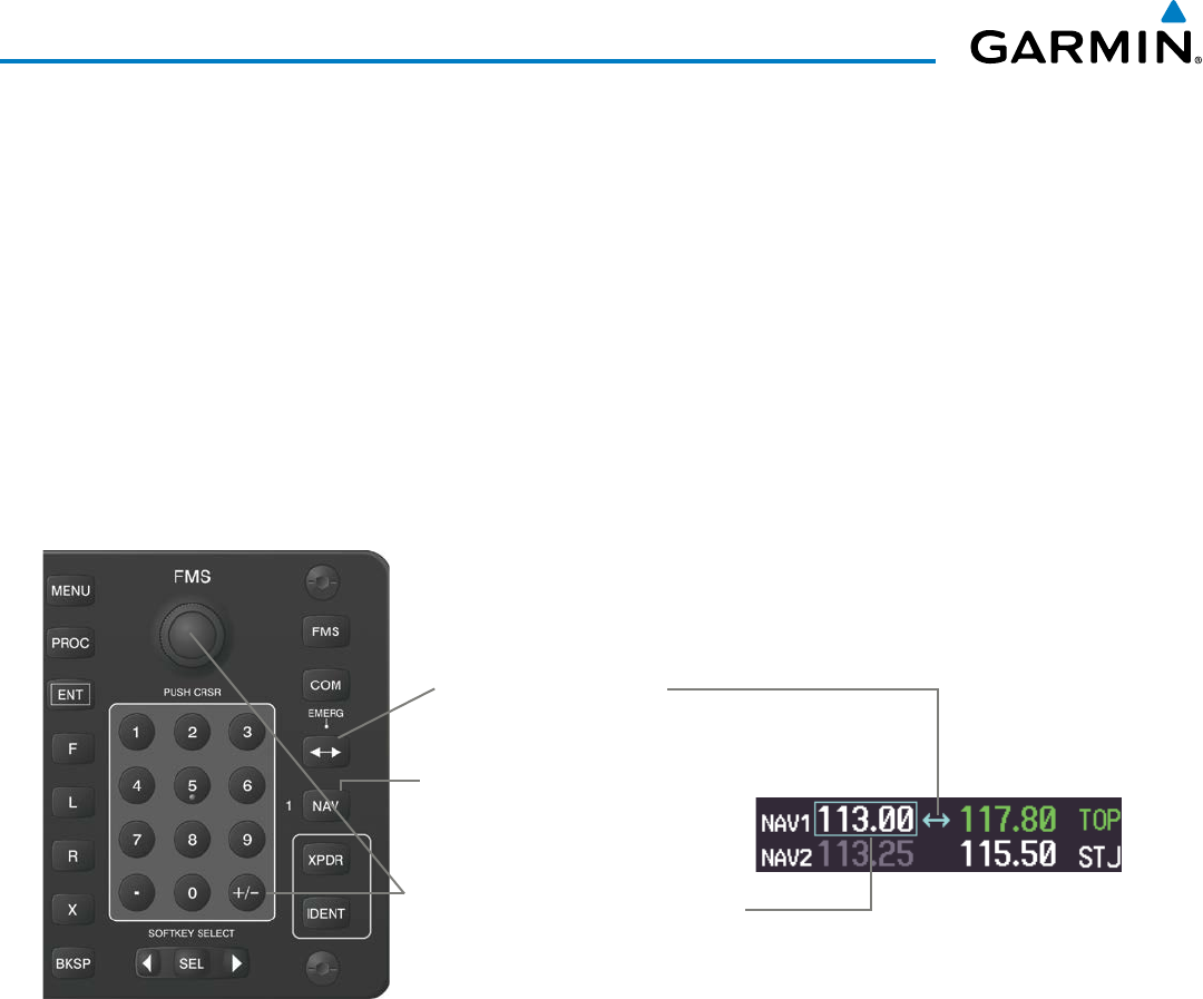
190-00928-04 Rev. A
Garmin G1000 Pilot’s Guide for the Beechcraft 200/B200 Series
124
AUDIO PANEL AND CNS
Manual NAV frequency tuning from the Control Unit
1) Press the NAV Key to enable the FMS Knob for NAV tuning. The NAV Tuning Selection Box is shown.
2) Press the NAV Key again, if needed, to select the desired NAV radio (1 or 2).
3) Turn the FMS Knob to tune the desired frequency in the NAV Tuning Box (large knob for MHz; small knob for
kHz).
Or:
Press the numeric keys on the keypad to enter a Frequency.
4) Press the
Frequency Transfer
Key to transfer the frequency to the active field.
If an error is made during frequency entry with the numeric keypad, pressing the BKSP Key moves the cursor
back one space. If an incorrect frequency is entered, reenter the correct one using the same procedure.
Figure 4-23 Frequency Tuning from the Control Unit
Second, Turn the
FMS
Knob or Press
the Numeric Keys to Enter a Frequency
into the NAV Standby Frequency Box
Third, Press the
Frequency
Transfer
Key to Move the
Frequency to the Active Field.
First, Press the
NAV
Key to activate NAV
tuning from the
FMS
Knob or Numeric
Keypad
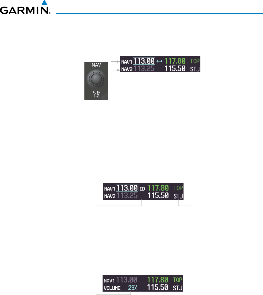
190-00928-04 Rev. A
Garmin G1000 Pilot’s Guide for the Beechcraft 200/B200 Series
125
AUDIO PANEL AND CNS
SELECTING THE RADIO TO BE TUNED
Press the small NAV Knob to transfer the frequency tuning selection and the Frequency Transfer Arrow
between NAV1 and NAV2.
Figure 4-24 Switching NAV Tuning Boxes
Press the
NAV
Knob to Switch
the tuning selection from one
NAV Radio to the other
VOR/LOC ID
When the Morse code Identifier audio is on for a NAV radio, a white ID appears to the left of the active
NAV frequency.
In the example shown, in order to listen to either station identifier, press the NAV1 or NAV2 Key on the
Audio Panel. Pressing the VOL/ID Knob turns off the Morse code audio only in the radio selected for tuning
(light blue numbers). To turn off both NAV IDs, transfer the tuning selection between NAV1 and NAV2 with
the small NAV Knob and press the VOL/ID Knob again to turn the Morse code off in the other radio.
Figure 4-25 NAV Radio ID Indication
The Morse Code Identifier
for the TOP VOR is On Station
Identifier
VOLUME
NAV Radio volume level can be adjusted from 0 to 100% using the
VOL/ID
Knob. Turning the knob
clockwise increases volume, counterclockwise decreases volume.
When adjusting, the level is displayed in place of the standby frequencies. Volume level indication remains
for two seconds after the change.
Figure 4-26 NAV Volume Level
NAV Volume Level
Remains for Two
Seconds
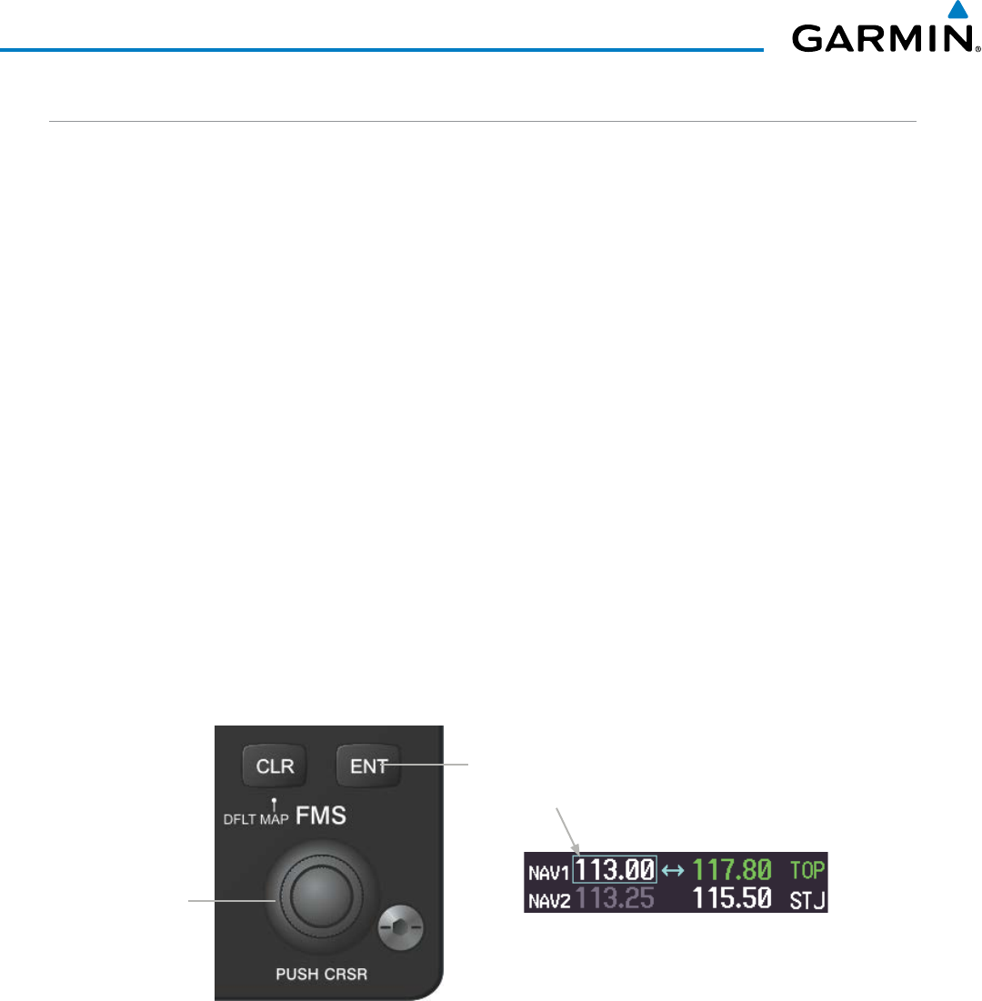
190-00928-04 Rev. A
Garmin G1000 Pilot’s Guide for the Beechcraft 200/B200 Series
126
AUDIO PANEL AND CNS
AUTO-TUNING A NAV FREQUENCY FROM THE MFD
NAV frequencies can be selected and loaded from the following MFD pages:
• WPT – Airport Information
• WPT – VOR Information
• NRST – Nearest Airports
• NRST – Nearest VOR
• NRST – Nearest Frequencies (FSS, WX)
• NRST – Nearest Airspaces
The MFD provides auto-tuning of NAV frequencies from waypoint and nearest pages. During enroute
navigation, the NAV frequency is entered automatically into the NAV standby frequency field. During approach
activation the NAV frequency is entered automatically into the NAV active frequency field.
Frequencies can be automatically loaded into the NAV Frequency Box from pages in the NRST or WPT page
group by highlighting the frequency and pressing the
ENT
Key (Figures 4-27, 4-28, and 4-29).
Auto-tuning a NAV frequency from the WPT and NRST Pages:
1) From any page that the NAV frequency can be auto-tuned, activate the cursor by pressing the FMS Knob or the
appropriate softkey.
2) Turn the FMS Knob to place the cursor on the desired NAV identifier or NAV frequency.
3) On the Nearest VOR and Nearest Airports pages, press the FREQ Softkey to place the cursor on the NAV
frequency (Figure 4-25).
4) Press the ENT Key to load the NAV frequency into the standby field of the selected NAV radio.
5) Press the Frequency Transfer Key to transfer the frequency to the NAV Active Frequency Field.
Press the
ENT
Key to Load a
Highlighted Frequency into the
NAV Standby Frequency Box.
Turn the
FMS
Knob to Scroll
Through a List
of Frequencies.
Figure 4-27 NAV Frequency Auto-Tuning from the MFD
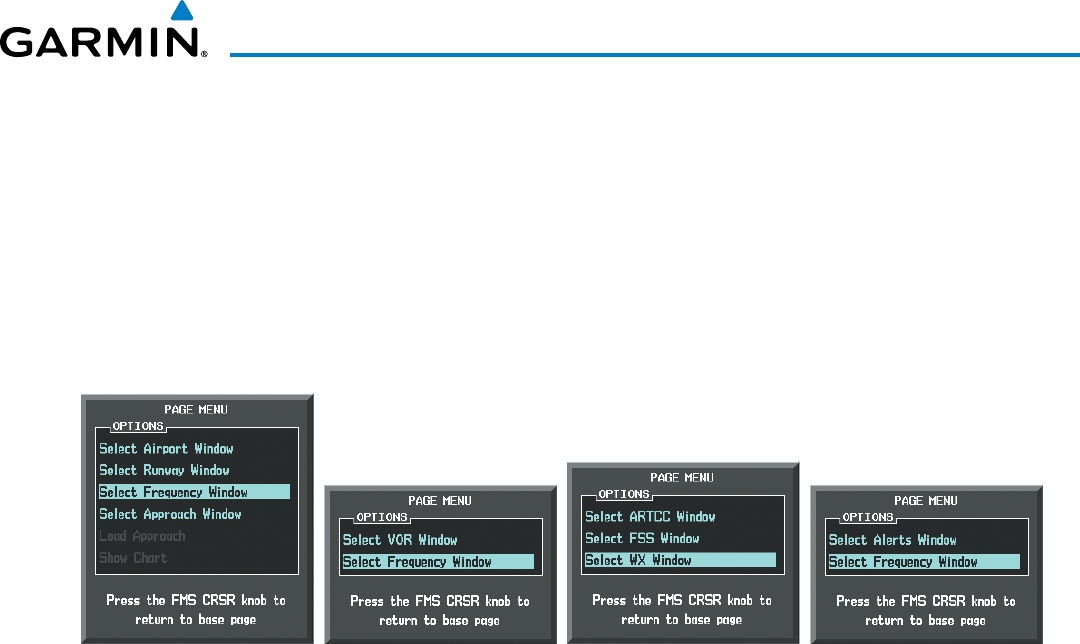
190-00928-04 Rev. A
Garmin G1000 Pilot’s Guide for the Beechcraft 200/B200 Series
127
AUDIO PANEL AND CNS
Or:
1) When on the NRST pages, press the MENU Key on the MFD control unit to display the page menu.
2) Turn the large FMS Knob to scroll through the menu options.
3) Press the ENT Key to place the cursor in the desired window.
4) Scroll through the frequency selections with the FMS Knob or the ENT Key.
5) Press the ENT Key to load the NAV frequency into the standby field of the selected NAV radio.
6) Press the Frequency Transfer Key to transfer the frequency to the NAV Active Frequency Field.
Figure 4-28 Nearest Pages Menus
Nearest Airspaces MenuNearest Airports Menu Nearest Frequencies MenuNearest VOR Menu
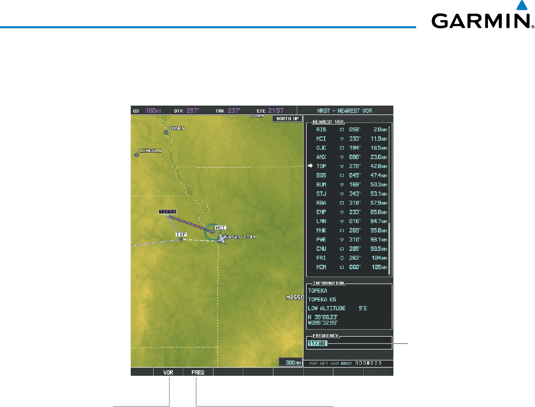
190-00928-04 Rev. A
Garmin G1000 Pilot’s Guide for the Beechcraft 200/B200 Series
128
AUDIO PANEL AND CNS
In the example shown, the VOR list is selected with the VOR Softkey or from the page menu. The FMS Knob
or ENT Key is used to scroll through the list. The cursor is placed on the frequency with the FREQ Softkey and
loaded into the NAV Tuning Box with the ENT Key.
Select the
FREQ
Softkey
to Place the Cursor on
the VOR Frequency
Figure 4-29 Loading the NAV Frequency from the NRST – Nearest VOR Page
Press the
ENT
Key to Load
the Frequency
into the NAV
Standby Field.
Select the
VOR
Softkey
to Place the Cursor on
the VOR Identifier
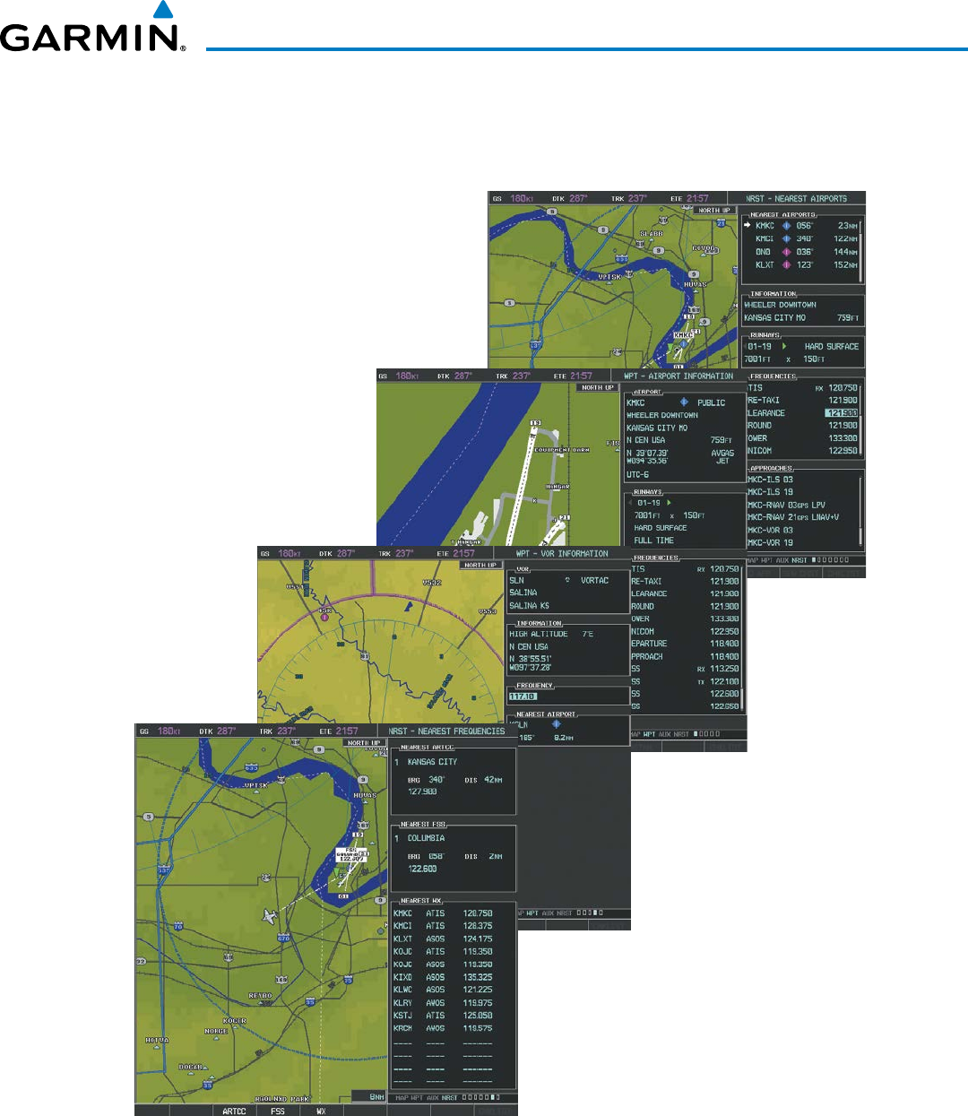
190-00928-04 Rev. A
Garmin G1000 Pilot’s Guide for the Beechcraft 200/B200 Series
129
AUDIO PANEL AND CNS
While enroute, NAV frequencies can also be auto-tuned from the NRST – Nearest Airports,
WPT – Airport Information, WPT – VOR Information, and NRST – Nearest Frequencies Pages on the MFD in
a similar manner using the appropriate softkeys or MENU Key, the FMS Knob, and the ENT Key.
Figure 4-30 NRST – Nearest Frequencies, WPT – VOR Information, WPT – Airport Information, and
NRST – Nearest Airports Pages

190-00928-04 Rev. A
Garmin G1000 Pilot’s Guide for the Beechcraft 200/B200 Series
130
AUDIO PANEL AND CNS
AUTO-TUNING NAV FREQUENCIES ON APPROACH ACTIVATION
NOTE: The primary NAV frequency is auto-tuned upon loading a VOR or ILS/Localizer approach.
NOTE: When an ILS/LOC approach has been activated in GPS Mode, the system switches to NAV Mode as
the final approach course is intercepted (within 15 nm of the FAF). See the Flight Management Section for
details.
NAV frequencies are automatically loaded into the NAV Frequency field on approach activation, on both
PFD1 and PFD2.
When loading or activating a VOR or ILS/LOC approach, the approach frequency is automatically transferred
to a NAV frequency field as follows:
• If the current CDI navigation source is GPS, the approach frequency is transferred to the NAV1 or NAV2
active frequency fields. The frequency that was previously in the NAV1 or NAV2 active frequency fields are
transferred to standby.
• If the current CDI navigation source is GPS, and if the approach frequency is already loaded into the NAV1
or NAV2 standby frequency field, the standby frequency is transferred to active.
• If the current CDI navigation source is NAV1 or NAV2, the approach frequency is transferred to the standby
frequency fields of the selected CDI NAV radio.
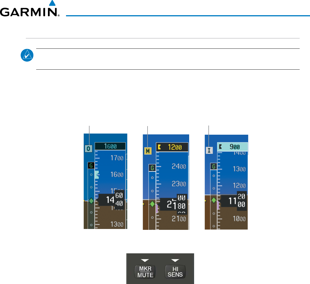
190-00928-04 Rev. A
Garmin G1000 Pilot’s Guide for the Beechcraft 200/B200 Series
131
AUDIO PANEL AND CNS
MARKER BEACON RECEIVER
NOTE: The marker beacon indicators operate independently of marker beacon audio and cannot be turned
off.
The marker beacon receiver is used as part of an ILS. The marker beacon receiver is always on and detects
any marker beacon signals within the reception range of the aircraft.
The receiver detects the three marker tones – outer, middle, and inner – and provides the marker beacon
annunciations located to the left of the Altimeter on the PFD.
Figure 4-31 Marker Beacon Annunciations on the PFD
Outer Marker
Indication Middle Marker
Indication Inner Marker
Indication
Figure 4-32 Marker Beacon Keys
The Audio Panels provide three different states of marker beacon operation; On, Muted, and Deselected.
Pressing the
MKR/MUTE
Key selects and deselects marker beacon audio. The key annunciator indicates when
marker beacon audio is selected.
During marker beacon audio reception, pressing the
MKR/MUTE
Key mutes the audio but does not affect the
marker annunciations (Figure 4-31). The marker tone is silenced, then waits for the next marker tone. The
MKR/MUTE
Key Annunciator is illuminated, indicating audio muting. The audio returns when the next marker
beacon signal is received. If the
MKR/MUTE
Key is pressed during signal reception (O, M, I indication) while
marker beacon audio is muted, the audio is deselected and the
MKR/MUTE
Key Annunciator is extinguished.
Pressing the HI SENS Key switches between high and low marker beacon receiver sensitivity. The HI SENS
function (annunciator illuminated) is used to provide an earlier indication when nearing a marker during an
approach. The LO SENS function (annunciator extinguished) results in a narrower marker dwell while over a
station.
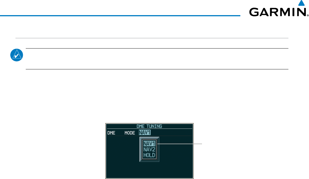
190-00928-04 Rev. A
Garmin G1000 Pilot’s Guide for the Beechcraft 200/B200 Series
132
AUDIO PANEL AND CNS
DME TUNING
NOTE: When turning on the G1000 for use, the system remembers the last frequency used for DME tuning
and the NAV1
,
NAV2,
or
HOLD
state prior to shutdown.
The G1000 System tunes the optional DME transceiver. The UHF DME frequency is tuned by pairing with a
VHF NAV frequency. DME frequency pairing is automatic and only the VHF NAV frequency is shown.
The DME Tuning Window is located to the right of the HSI in the lower right corner of the PFD. The DME
transceiver is tuned by selecting NAV1, NAV2, or HOLD in the DME Tuning Window. Pressing the
DME
Softkey switches the DME Tuning Window on and off.
Figure 4-33 DME Tuning Window
DME
Modes
The following DME transceiver pairing can be selected:
• NAV1 – Pairs the DME frequency from the selected NAV1 frequency.
• NAV2 – Pairs the DME frequency from the selected NAV2 frequency.
• HOLD – When in the HOLD position, the DME frequency remains paired with the last selected NAV
frequency.
Selecting DME transceiver pairing:
1) Press the DME Softkey to display the DME Tuning Window.
2) Turn the small
FMS
Knob to select the DME tuning mode.
3) Press the
ENT
Key to complete the selection.
Pressing the CLR Key or FMS Knob while in the process of DME pairing cancels the tuning entry and reverts
back to the previously selected DME tuning state. Pressing the FMS Knob activates/deactivates the cursor in
the DME Tuning Window.
See the Flight Instruments Section for displaying the DME information window.

190-00928-04 Rev. A
Garmin G1000 Pilot’s Guide for the Beechcraft 200/B200 Series
133
AUDIO PANEL AND CNS
4.4 MODE S TRANSPONDERS
The GTX 33, GTX 33D (optional), GTX 33ES (optional), and GTX 3000 (optional) Mode S Transponders
provide Mode A, Mode C, and Mode S interrogation and reply capabilities. Selective addressing or Mode Select
(Mode S) capability includes the following features:
• Level-2 reply data link capability (used to exchange information between aircraft and ATC facilities)
• Surveillance identifier capability
• Flight ID (Flight Identification) reporting – The Mode S Transponder reports aircraft identification as either the
aircraft registration or a unique Flight ID.
• Altitude reporting
• Airborne status determination
• Transponder capability reporting
• Mode S Enhanced Surveillance (EHS) requirements
• Acquisition squitter – Acquisition squitter, or short squitter, is the transponder 24-bit identification address.
The transmission is sent periodically, regardless of the presence of interrogations. The purpose of acquisition
squitter is to enable Mode S ground stations and aircraft equipped with a Traffic Avoidance System (TAS) to
recognize the presence of Mode S-equipped aircraft for selective interrogation.
• Extended squitter – Transmits the Automatic Dependent Surveillance-Broadcast (ADS-B) position, velocity, and
heading information periodically without requiring an interrogation.
The Hazard Avoidance Section provides more details on traffic avoidance systems.
GTX 33 TRANSPONDER CONTROLS
Transponder function is displayed on three levels of softkeys on the PFD: Top-level, Mode Selection, and
Code Selection. When the top-level
XPDR
Softkey is selected, the Mode Selection softkeys appear:
XPDR1,
XPDR2, STBY
,
ON
,
ALT
,
VFR
,
CODE
,
IDENT
,
BACK
.
When the
CODE
Softkey is selected, the number softkeys appear:
0
,
1,
2
,
3
,
4
,
5
,
6
,
7
,
IDENT
,
BKSP,
BACK
. The digits
8
and
9
are not used for code entry. Selecting the numbered softkeys in sequence enters
the transponder code. If an error is made, selecting the
BKSP
Softkey moves the code selection cursor to the
previous digit. Selecting the
BKSP
Softkey again moves the cursor to the next previous digit.
Selecting the
BACK
Softkey during code selection reverts to the Mode Selection Softkeys. Selecting the
BACK
Softkey during mode selection reverts to the top-level softkeys.
The code can also be entered with the FMS Knob on either PFD. Code entry must be completed with either
the softkeys or the FMS Knob, but not a combination of both.
Selecting the
IDENT
Softkey while in Mode or Code Selection initiates the ident function and reverts to the
top-level softkeys.
After 45 seconds of transponder control inactivity, the system reverts back to the top-level softkeys.
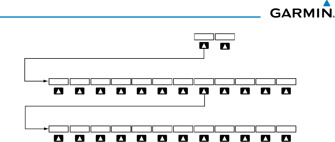
190-00928-04 Rev. A
Garmin G1000 Pilot’s Guide for the Beechcraft 200/B200 Series
134
AUDIO PANEL AND CNS
Figure 4-34 Transponder Softkeys (PFD)
Selecting the BACK Softkey
returns to the top-level softkeys.
ALERTS
ALERTS
BACK BKSP
IDENT
7 6 5 4 3 2 1 0
STBY ON ALT VFR CODE IDENT BACK
XPDR IDENT
Selecting the BACK Softkey returns to the mode selection softkeys.
XPDR1 XPDR2
Selecting and activating Transponder 1 or Transponder 2:
1) Select the
XPDR
Softkey to display the Transponder Mode Selection Softkeys.
2) Select the
XPDR1
or
XPDR2
Softkey to select and activate the desired transponder.
When turning on the G1000 for use, the system activates Transponder 1 as the default unit, regardless of
which transponder was active prior to shutdown. When switching between Transponder 1 and Transponder 2,
the code and mode remain the same. If a new code is entered in the active transponder, switching transponders
does not bring back the previous code.
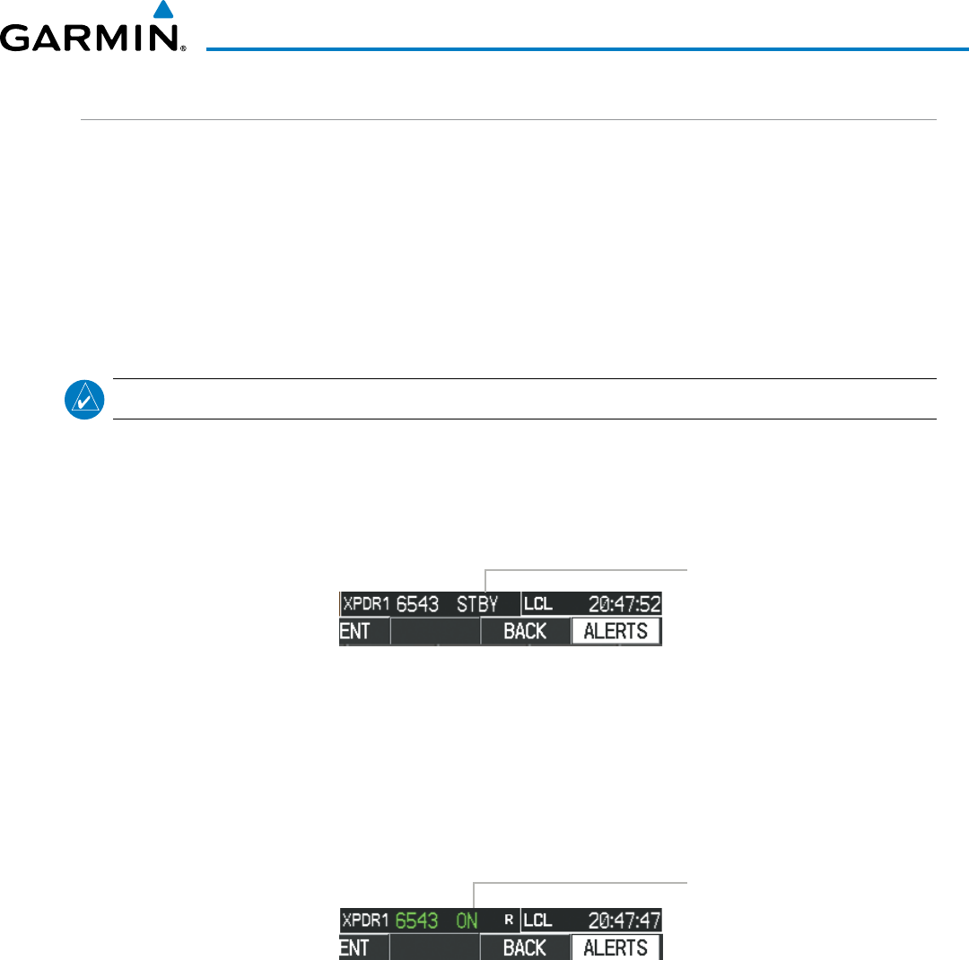
190-00928-04 Rev. A
Garmin G1000 Pilot’s Guide for the Beechcraft 200/B200 Series
135
AUDIO PANEL AND CNS
GTX 33 TRANSPONDER MODE SELECTION
Mode selection can be automatic (Ground and Altitude Modes) or manual (Standby, ON, and Altitude Modes).
The
STBY
,
ON,
and
ALT
Softkeys can be accessed by selecting the
XPDR
Softkey.
Selecting a transponder mode:
1) Select the
XPDR
Softkey to display the Transponder Mode Selection Softkeys.
2) Select the desired softkey to activate the transponder mode.
STANDBY MODE (MANUAL)
NOTE: In Standby Mode, the IDENT function is inhibited.
Standby Mode can be selected at any time by selecting the
STBY
Softkey. In Standby, the transponder does
not reply to interrogations, but new codes can be entered. When Standby is selected, a white
STBY
indication
and transponder code appear in the mode field of the Transponder Data Box. In all other modes, these fields
appear in green.
STBY Mode (White
Code Number and
Mode)
Figure 4-35 Standby Mode
MANUAL ON MODE
ON Mode can be selected at any time by selecting the ON Softkey. ON Mode generates Mode A and Mode S
replies, but Mode C altitude reporting is inhibited. In ON Mode, a green ON indication and transponder
code appear in the mode field of the Transponder Data Box.
ON Mode
(No Altitude
Reporting)
Figure 4-36 ON Mode
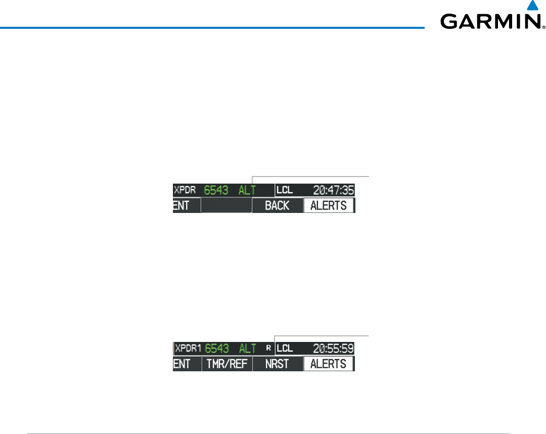
190-00928-04 Rev. A
Garmin G1000 Pilot’s Guide for the Beechcraft 200/B200 Series
136
AUDIO PANEL AND CNS
ALTITUDE MODE (AUTOMATIC OR MANUAL)
Altitude Mode is automatically selected when the aircraft becomes airborne. Altitude Mode may also be
selected manually by selecting the
ALT
Softkey.
If Altitude Mode is selected, a green ALT indication and transponder code appear in the mode field of the
Transponder Data Box, and all transponder replies requesting altitude information are provided with pressure
altitude information.
ALT Mode
(Mode C Altitude
Reporting)
Figure 4-37 Altitude Mode
REPLY STATUS
When the transponder sends replies to interrogations, a white R indication appears momentarily in the
reply status field of the Transponder Data Box.
Reply to
Interrogation
Figure 4-38 Reply Indication
TCAS II TRANSPONDER CONTROLS (OPTIONAL)
Transponder function is displayed on three levels of softkeys on the PFD: Top-level, Transponder/Traffic
Selection, and Mode Selection or Code Entry. When the top-level
XPDR/TFC
Softkey is selected, the Function
Select softkeys appear:
XPDR1, XPDR2,
MODE, TCAS, CODE
,
IDENT
,
BACK
.
When the
MODE
Softkey is selected, the Mode Selection softkeys appear:
STBY
,
ON
,
ALT
,
TA ONLY
,
TA/
RA
,
BACK
.
When the
CODE
Softkey is selected, the number softkeys appear:
0
,
1,
2
,
3
,
4
,
5
,
6
,
7
,
IDENT
,
BKSP,
BACK
. The digits
8
and
9
are not used for code entry. Selecting the numbered softkeys in sequence enters
the transponder code. If an error is made, selecting the
BKSP
Softkey moves the code selection cursor to the
previous digit. Selecting the
BKSP
Softkey again moves the cursor to the next previous digit.
Selecting the
BACK
Softkey returns to the previous level softkeys.
The code can also be entered with the FMS Knob on either PFD. Code entry must be completed with either
the softkeys or the FMS Knob, but not a combination of both.
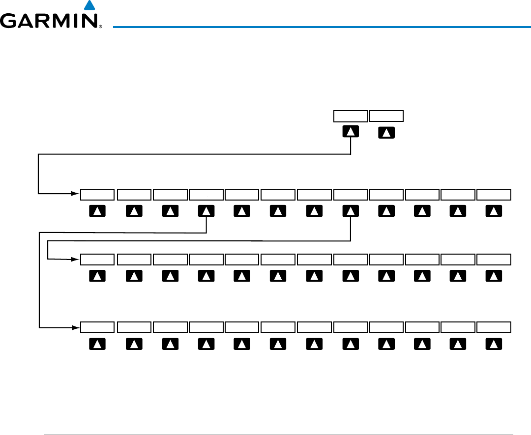
190-00928-04 Rev. A
Garmin G1000 Pilot’s Guide for the Beechcraft 200/B200 Series
137
AUDIO PANEL AND CNS
Selecting the
IDENT
Softkey while in Code Selection initiates the ident function and reverts to the top-level
softkeys.
After 45 seconds of transponder control inactivity, the system reverts back to the top-level softkeys.
Figure 4-39 Transponder Softkeys (with TCAS II option)
Selecting the BACK Softkey
returns to the top-level softkeys.
MSG
MSG
BACKBKSP
IDENT
76543210
MODE TCAS CODE IDENT BACK
XPDR/TFC
IDENT
Selecting the BACK Softkey
returns to the previous level softkeys.
MSG
STBY ON ALTTA/RA BACK
TA ONLY
Selecting the BACK Softkey
returns to the previous level softkeys.
XPDR1 XPDR2
(optional) (optional)
TCAS II TRANSPONDER MODE SELECTION (OPTIONAL)
Mode selection can be automatic (Altitude Mode) or manual (Standby, On, and Altitude Modes). The
STBY
,
ON,
ALT, TA ONLY,
and
TA/RA
Softkeys can be accessed by selecting the
XPDR/TFC
Softkey, then the
MODE
Softkey.
Selecting a transponder mode:
1) Select the
XPDR/TFC
Softkey.
2) Select the
MODE
Softkey to display the Transponder Mode Selection Softkeys.
3) Select the desired softkey to activate the transponder mode (STBY, ON, or ALT).
Selecting a TCAS II mode:
1) Select the
XPDR/TFC
Softkey.
2) Select the
MODE
Softkey to display the TCAS II Mode Selection Softkeys.
3) Select the desired softkey to activate the TCAS II mode (TA ONLY or TA/RA).
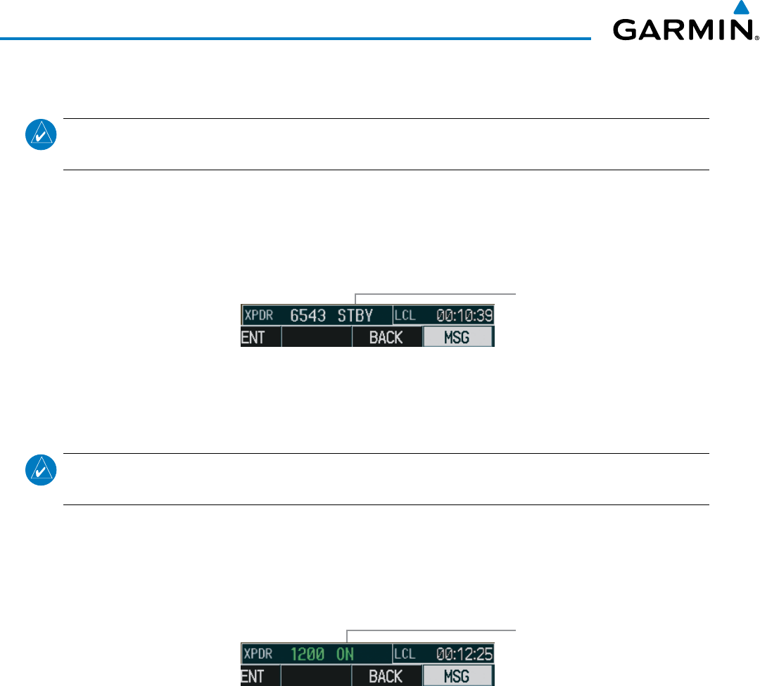
190-00928-04 Rev. A
Garmin G1000 Pilot’s Guide for the Beechcraft 200/B200 Series
138
AUDIO PANEL AND CNS
STANDBY MODE (MANUAL)
NOTE: In Standby Mode, the IDENT function is inhibited. TCAS II is switched to Standby Mode, because the
transponder is not capable of supporting TCAS II operation in Standby Mode.
Standby Mode can be selected at any time by selecting the
STBY
Softkey. In Standby, the transponder does
not reply to interrogations, but new codes can be entered. When Standby is selected, a white
STBY
indication
and transponder code appear in the mode field of the Transponder Data Box. In all other modes, these fields
appear in green.
STBY Mode (White
Code Number and
Mode)
Figure 4-40 Standby Mode
ON MODE (MANUAL)
NOTE: TCAS II is switched to Standby Mode, because the transponder is not capable of supporting TCAS II
operation in On Mode.
ON Mode can be selected at any time by selecting the ON Softkey. ON Mode generates Mode A replies,
but Mode C altitude reporting is inhibited. Acquisition squitter and replies to discretely addressed Mode S
interrogations are also permitted. In ON Mode, a green ON indication and transponder code appear in the
mode field of the Transponder Data Box.
ON Mode
(No Altitude
Reporting)
Figure 4-41 ON Mode
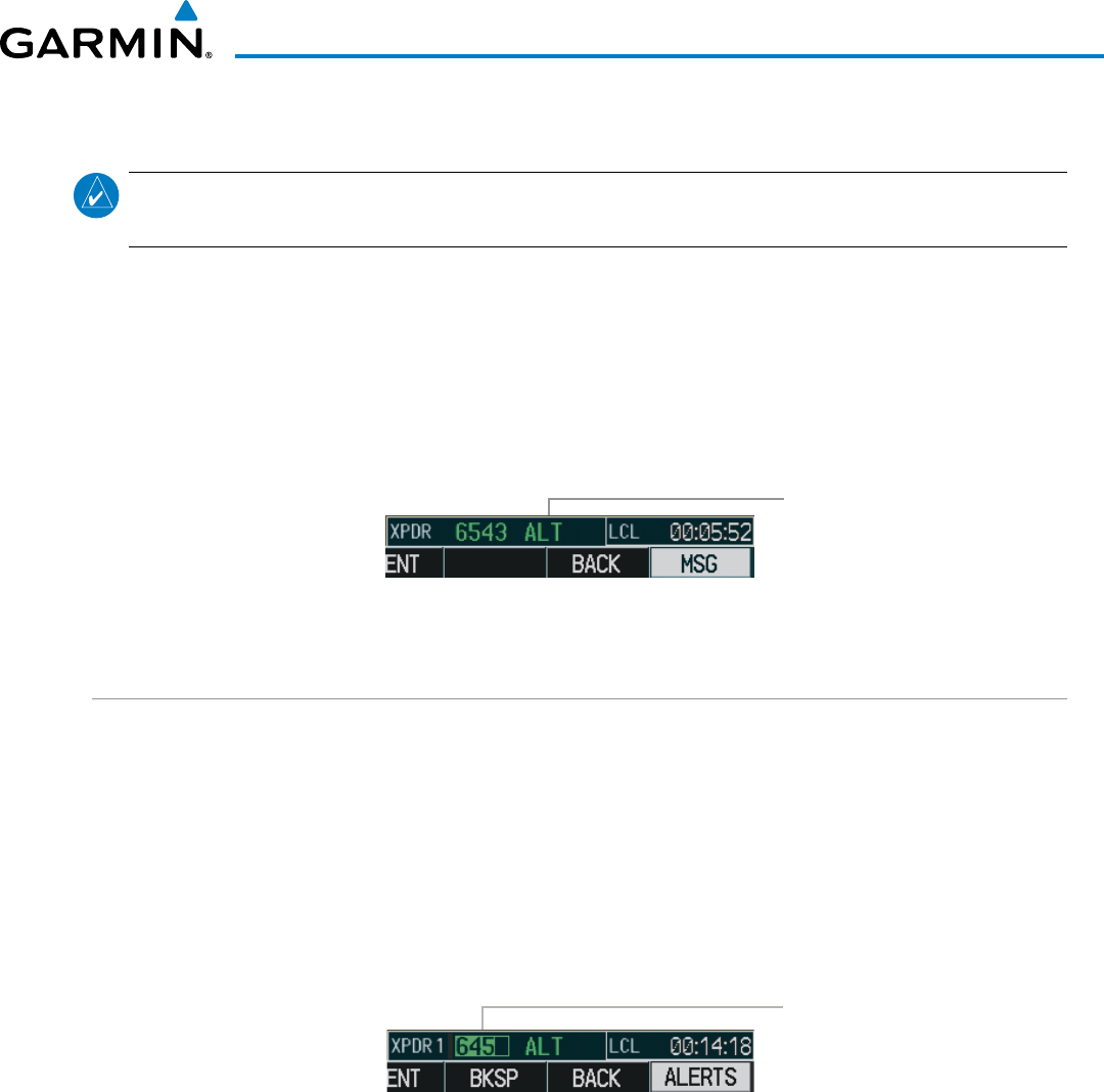
190-00928-04 Rev. A
Garmin G1000 Pilot’s Guide for the Beechcraft 200/B200 Series
139
AUDIO PANEL AND CNS
ALTITUDE MODE (AUTOMATIC OR MANUAL)
NOTE: TCAS II is switched to Standby Mode when the altitude mode is manually selected using the ALT
Softkey.
Altitude Mode is automatically selected when the aircraft becomes airborne. Altitude Mode may also be
selected manually by selecting the
ALT
Softkey. ALT Mode generates Mode A and Mode C replies. Acquisition
squitter and replies to discretely addressed Mode S interrogations are also permitted.
If Altitude Mode is selected, a green ALT indication and transponder code appear in the mode field of the
Transponder Data Box, and all transponder replies requesting altitude information are provided with pressure
altitude information.
ALT Mode
(Mode C Altitude
Reporting)
Figure 4-42 Altitude Mode
ENTERING A TRANSPONDER CODE
Entering a transponder code with softkeys:
1) Select the
XPDR
or
XPDR/TFC
Softkey to display the Transponder Mode Selection Softkeys.
2) Select the
CODE
Softkey to display the Transponder Code Selection Softkeys, for digit entry.
3) Select the digit softkeys to enter the code in the code field. When entering the code, the next softkey in sequence
must be selected within 10 seconds, or the entry is cancelled and restored to the previous code. Selecting the
BKSP Softkey moves the code selection cursor to the previous digit. Five seconds after the fourth digit has been
entered, the transponder code becomes active.
Entering
a Code
Figure 4-43 Entering a Code
Entering a transponder code with the PFD FMS Knob:
1) Select the
XPDR
or
XPDR/TFC
and the
CODE
Softkeys as in the previous procedure to enable code entry.
2) Turn the small FMS Knob to enter the first two code digits.
3) Turn the large FMS Knob to move the cursor to the next code field.
4) Enter the last two code digits with the small FMS Knob.
5) Press the
ENT
Key to complete code digit entry.
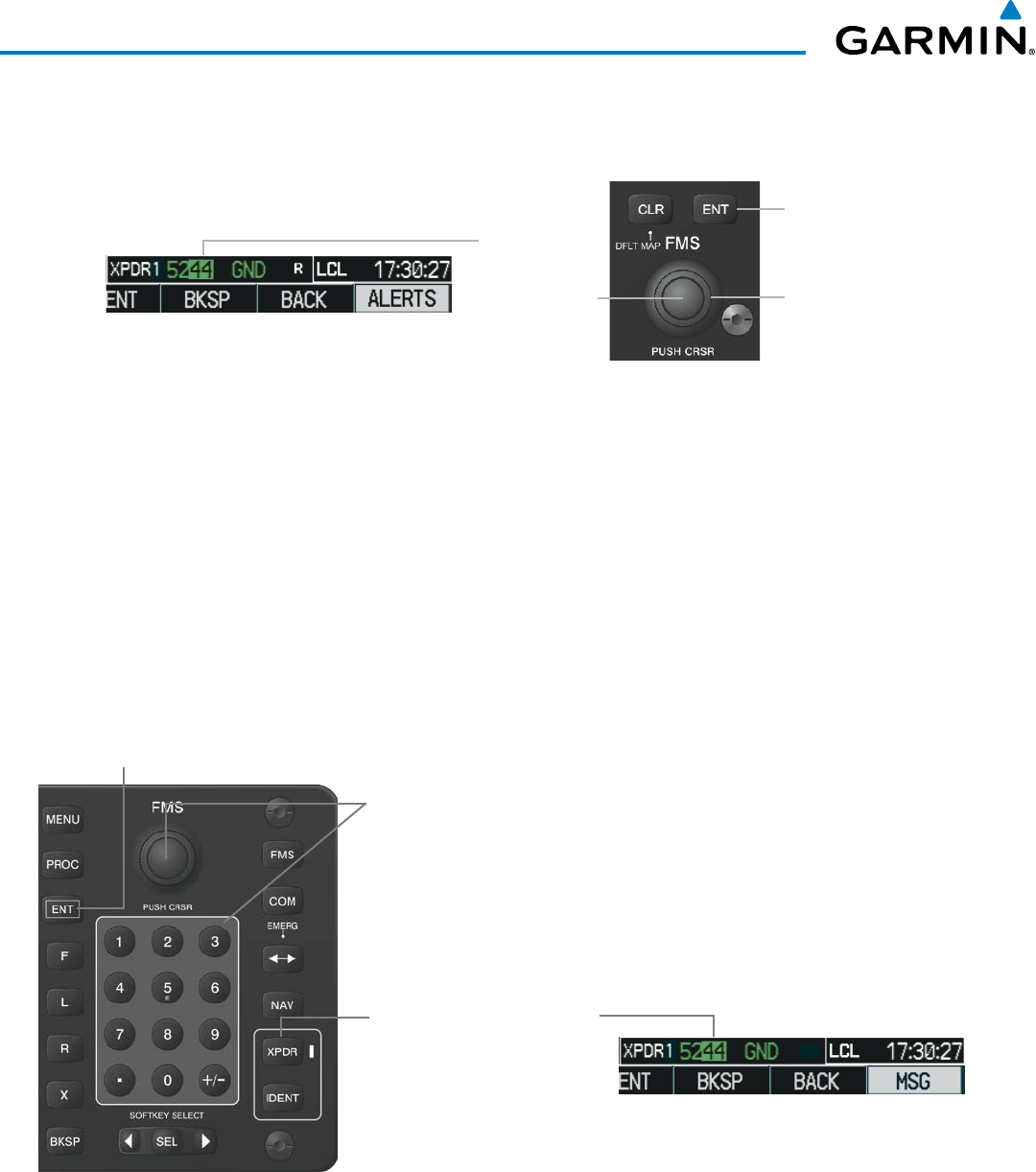
190-00928-04 Rev. A
Garmin G1000 Pilot’s Guide for the Beechcraft 200/B200 Series
140
AUDIO PANEL AND CNS
Pressing the CLR Key or small FMS Knob before code entry is complete cancels code entry and restores the
previous code. Waiting for 10 seconds after code entry is finished activates the code automatically.
Figure 4-44 Entering a Code with the FMS Knob
Press the
ENT
Key
to Complete Code
Entry
Turn the Large
FMS
Knob to
Move the Cursor
to the Next
Code Field
Turn the Small
FMS
Knob to
Enter Two Code
Digits at a Time
Manual code entry from the Control Unit
1) Press the XPDR Key to select the transponder code field.
2) Turn the small FMS Knob on the PFD to enter the first two code digits, turn the large FMS Knob to select the
last two digits, and turn the small FMS Knob to enter the last two code digits.
Or:
Press the numeric keys on the keypad to enter a code.
If an error is made during code entry with the numeric keypad, pressing the BKSP Key moves the cursor
back one space. If an incorrect code is entered, reenter the correct one using the same procedure.
Figure 4-45 Transponder Code Entry from the Control Unit
Second, Turn the
FMS
Knob, Small
Knob to Enter Two Code Digits at a
Time, Large Knob to Move the Cursor
to the Next Code Field, or Press the
Numeric Keys to Enter a Code into the
Transponder Data Box
First, Press the
XPDR
Key to
Activate Code Entry from the
FMS
Knob or Numeric Keypad
into the Transponder Data Box
Third, Press
ENT
Key to
Complete Code Entry
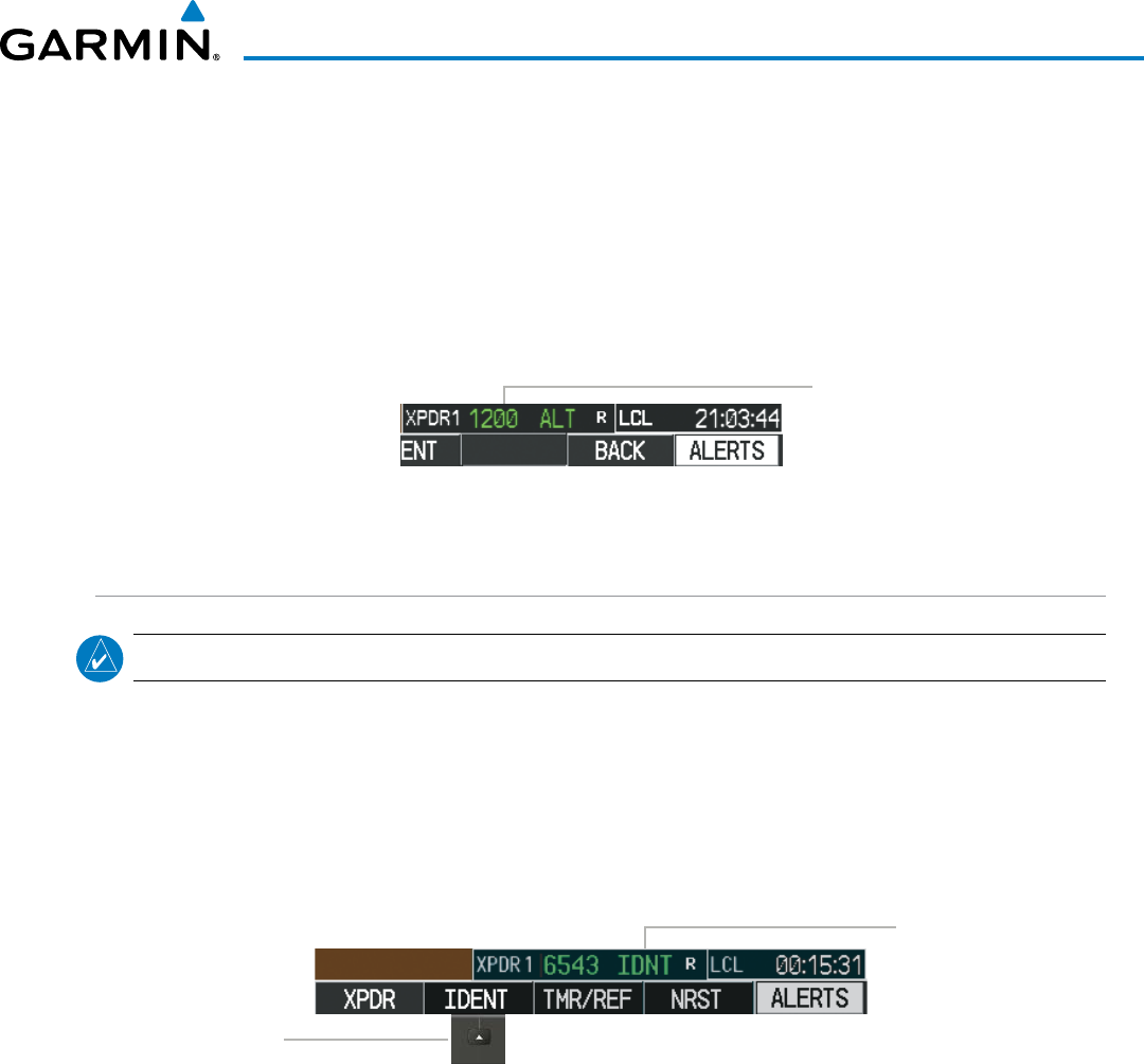
190-00928-04 Rev. A
Garmin G1000 Pilot’s Guide for the Beechcraft 200/B200 Series
141
AUDIO PANEL AND CNS
VFR CODE
The VFR code can be entered either manually or by selecting the
XPDR
or XPDR/TFC Softkey, then the
VFR
Softkey. When the
VFR
Softkey is selected, the pre-programmed VFR code is automatically displayed in the
code field of the Transponder Data Box. Selecting the
VFR
Softkey again restores the previous identification
code.
The pre-programmed VFR Code is set at the factory to 1200. If a VFR code change is required, contact a
Garmin-authorized service center for configuration.
Figure 4-46 VFR Code
VFR Code
IDENT FUNCTION
NOTE: In Standby Mode, the IDENT Softkey is inoperative.
Selecting the
IDENT
Softkey sends a distinct identity indication to Air Traffic Control (ATC). The indication
distinguishes the identing transponder from all the others on the air traffic controller’s screen. The
IDENT
Softkey appears on all levels of transponder softkeys. When the
IDENT
Softkey is selected, a green
IDNT
indication is displayed in the mode field of the Transponder Data Box for a duration of 18 seconds.
After the
IDENT
Softkey is selected while in Mode or Code Selection, the system reverts to the top-level
softkeys.
Select the
IDENT Softkey
to Initiate the
ID Function
IDNT
Indication
Figure 4-47 IDENT Softkey and Indication
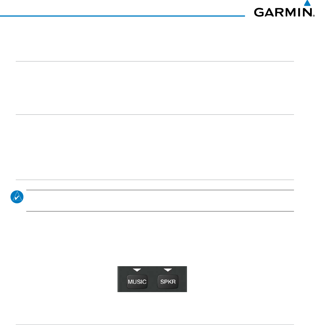
190-00928-04 Rev. A
Garmin G1000 Pilot’s Guide for the Beechcraft 200/B200 Series
142
AUDIO PANEL AND CNS
4.5 ADDITIONAL AUDIO PANEL FUNCTIONS
POWER-UP
The Audio Panels perform a self-test during power-up. During the self-test all Audio Panel annunciator lights
illuminate for approximately two seconds. Once the self-test is completed, most of the settings are restored to
those in use before the unit was last turned off. The exceptions are the speaker and intercom, which are always
selected during power up.
MONO/STEREO HEADSETS
Stereo headsets are recommended for use in this aircraft.
Using a monaural headset in a stereo jack shorts the right headset channel output to ground. While this does
not damage the Audio Panel, a person listening on a monaural headset hears only the left channel in both ears.
If a monaural headset is used at one of the passenger positions, any other passenger using a stereo headset hears
audio in the left ear only.
SPEAKER
NOTE: When the oxygen mask switch on the instrument panel is selected, each pilot’s microphone audio is
heard on the cross-side speaker. The on-side speaker is also enabled and cannot be deselected.
Each Audio Panel is connected to a separate flight deck speaker for listening to all of the radios. Each SPKR
Key controls the on-side speaker unless oxygen masks are in use. During oxygen mask use the on-side speaker
is always enabled.
Pressing the SPKR Key selects and deselects the speaker. Except for oxygen mask use, speaker audio is
muted when the PTT Key is pressed.
Figure 4-48 Speaker Key
UNMUTED INPUTS
Aural alerts are always present on the headset and are on the speaker when the SPKR is selected. These
warnings and the aircraft radios are not heard on the passenger headphones.
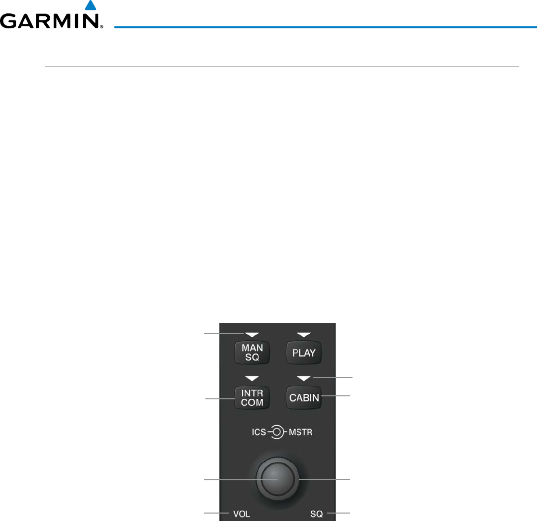
190-00928-04 Rev. A
Garmin G1000 Pilot’s Guide for the Beechcraft 200/B200 Series
143
AUDIO PANEL AND CNS
INTERCOM
Pressing the INTR COM Key on either Audio Panel selects and deselects the intercom on both Audio Panels.
The annunciator is lit when the intercom is active. The intercom connects the pilot and copilot together. Either
the pilot or copilot may select or deselect the intercom.
The CABIN Key initiates two way communication between the pilot or copilot and the passengers in the
cabin. The annunciator is lit when the cabin intercom is active on either Audio Panel.
When the flight crew wants to communicate with the passengers, the pilot or copilot presses the CABIN
Key to signal that communication is desired. The cabin signal must be acknowledged to begin intercom
conversation.
The MAN SQ Key allows either automatic or manual control of the intercom squelch setting. Pressing the
MAN SQ Key enables manual squelch control, indicated by the MAN SQ annunciator.
• When the MAN SQ Annunciator is extinguished (Automatic Squelch is on), the
ICS
Knob controls only the
volume (pressing the
ICS
Knob has no effect on the VOL/SQ selection).
• When the MAN SQ Annunciator is illuminated (Manual Squelch), the
ICS
Knob controls either volume or
squelch (selected by pressing the ICS Knob and indicated by the VOL or SQ annunciation).
Pilot/Copilot
ICS
Manual Squelch
Annunciator; Off
for Automatic
Squelch, On for
Manual Squelch
Press to switch
between VOL and SQ.
Turn to adjust Squelch
when SQ Annunciation
is lit, Volume when
VOL Annunciation is lit.
Volume Annunciation Squelch Annunciation
Master Volume
Control for Pilot
Side or Copilot
Side
Figure 4-49 Intercom Controls
Selects and Deselects
Cabin Intercom
Cabin Annunciator; On for
Cabin Intercom, Flashes for
Cabin to Flight Deck Hail
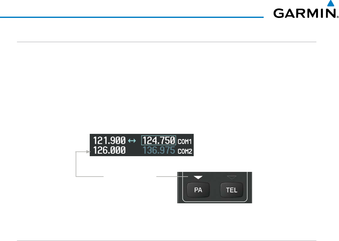
190-00928-04 Rev. A
Garmin G1000 Pilot’s Guide for the Beechcraft 200/B200 Series
144
AUDIO PANEL AND CNS
PASSENGER ADDRESS (PA) SYSTEM
A passenger address system is provided by pressing the PA Key to deliver messages to the passengers. The
message is heard by the other pilot on the headset only if the INTR COM Key is enabled. PA messages are one
way from the flight deck to the passengers.
A Push-to-talk (PTT) must be pressed to deliver PA announcements to the passengers over their
headphones.
When PA is selected on the Audio Panel, the annunciator flashes about once per second while pressing the
PTT, the COM MIC annunciator is no longer lit, and the active COM frequency for that Audio Panel changes to
white, indicating that there is no COM selected.
Figure 4-50 PA Key Selected for Cabin Announcements
PA Key is Selected on
the Audio Panel
SIMULTANEOUS COM OPERATION
Both the pilot and the copilot can transmit and receive simultaneously over separate COM radios. The
selected COM MIC Annunciator flashes when either pilot’s microphone PTT is pressed.
If both pilots select the same COM radio, the pilot has priority on COM1 and the copilot has priority on
COM2.
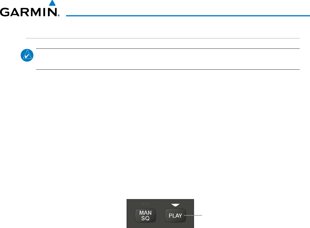
190-00928-04 Rev. A
Garmin G1000 Pilot’s Guide for the Beechcraft 200/B200 Series
145
AUDIO PANEL AND CNS
CLEARANCE RECORDER AND PLAYER
NOTE: Pressing the play key on the pilot’s Audio Panel plays recorded audio to the Pilot. Pressing the play
key on the Copilot’s Audio Panel plays recorded audio to the Copilot.
The Audio Panel contains a digital clearance recorder that continually records up to 2.5 minutes of the
selected COM radio signal. Recorded COM audio is stored in separate memory blocks. Once 2.5 minutes of
recording time have been reached, the recorder begins recording over the stored memory blocks, starting from
the oldest block.
The PLAY Key controls the play function. The PLAY annunciator remains lit to indicate when play is in
progress. The PLAY annunciator turns off after playback is finished.
Pressing the PLAY Key once plays the latest recorded memory block and then returns to normal operation.
Pressing the PLAY Key again during play of a memory block stops play. If a COM input signal is detected
during play of a recorded memory block, play is halted.
Pressing the PLAY Key twice within one-half second while audio is playing plays the previous block of
recorded audio. Each subsequent two presses of the PLAY Key within one-half second backtracks through the
recorded memory blocks to reach and play any recorded block.
Powering off the unit automatically clears all recorded blocks.
Figure 4-51 Play Key
PLAY
Key
Controls the
Play Function
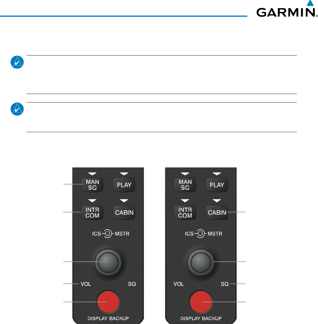
190-00928-04 Rev. A
Garmin G1000 Pilot’s Guide for the Beechcraft 200/B200 Series
146
AUDIO PANEL AND CNS
4.6 AUDIO PANELS PREFLIGHT PROCEDURE
NOTE: If the flight crew is using headsets that have a high/low switch or volume control knob, verify that
the switch is in the high position and the volume control on the headsets are at max volume setting. On
single-pilot flights, verify that all other headsets are not connected to avoid excess noise in the audio
system.
NOTE: When the MAN SQ Key is pressed, the flight crew is now able to set the ICS squelch manually. If
manual squelch is set to full open (SQ annunciated and the small knob turned counterclockwise) background
noise is heard in the ICS system as well as during COM transmissions.
After powering up the G1000 system the following steps aid the flight crew in maximizing the use of the Audio
Panels as well as prevent flight crew induced issues. These preflight procedures should be performed each time a
flight crew boards the aircraft to insure awareness of all audio levels in the Audio Panels and radios.
Pilot Side Copilot Side
Figure 4-52 Audio Panel Controls
Reversionary Mode
for PFD1 and MFD Reversionary Mode
for PFD2 and MFD
Cabin ICS
Automatic/Manual
Squelch
Volume Annunciation Squelch Annunciation
Pilot/Copilot
ICS
ICS Volume and
Squelch Control Master Volume
Control
Independent radio volume adjustments made using the PFD controls affect only the audio output for each
radio selected for adjustment. Radio volume adjustment affects both crew positions equally for each radio that
is adjusted. Turning the master volume control located on either Audio Panel affects only the audio heard in the
corresponding crew position headset. Thus, radio volume adjustments may be overridden by each crew position
independently using the master volume control on the Audio Panel for the respective crew position. The master
volume control for each Audio Panel affects all other system audio output for the pilot or copilot headset.
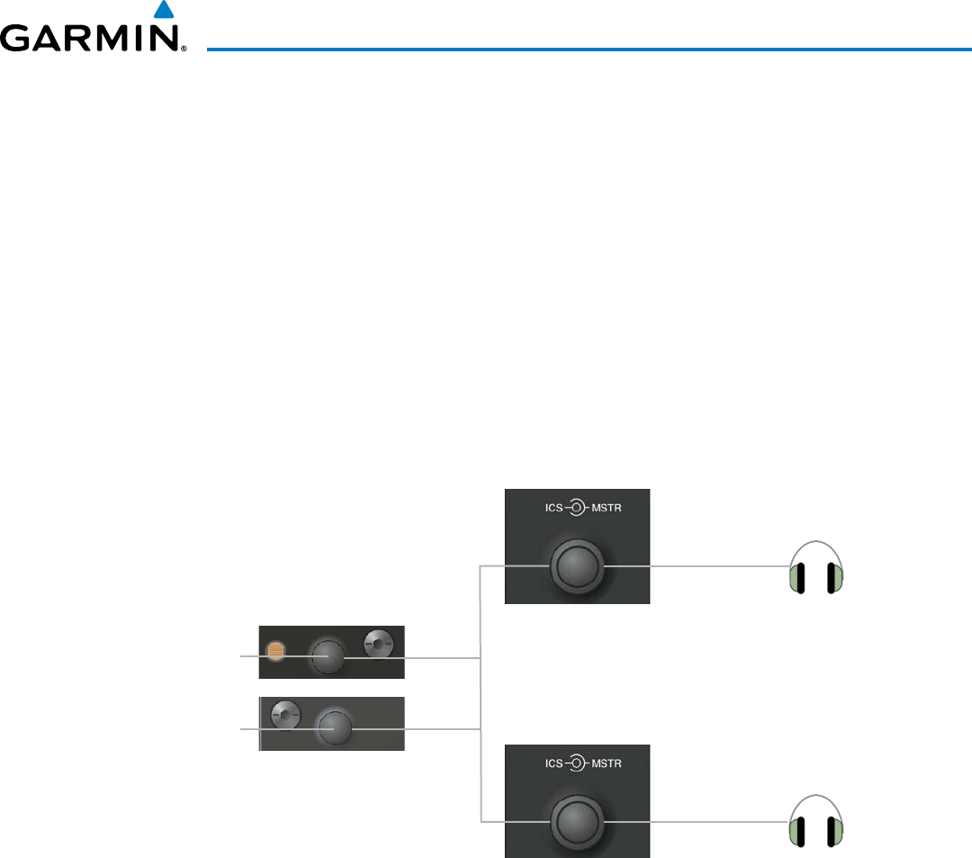
190-00928-04 Rev. A
Garmin G1000 Pilot’s Guide for the Beechcraft 200/B200 Series
147
AUDIO PANEL AND CNS
Setting the Audio Panels during preflight:
1) Verify that the INTR COM Key is selected.
2) Verify manual squelch is set to minimum.
3) Turn the MSTR Knob (Master Volume Control) on both Audio Panels clockwise two full turns. This sets the
headset audio level to max volume (least amount of attenuation).
4) Adjust radio volume levels (COM, NAV, etc.) to a suitable level.
5) Adjust the ICS volume Knob on each Audio Panel to the desired intercom level.
6) Reset squelch to automatic, or adjust to the appropriate level manually.
Once this procedure has been completed, the master volume controls on both Audio Panels may now be
adjusted. The flight crew can change settings, keeping in mind the notes above.
Figure 4-53 Radio and Headphone Volume Controls
Radio Volume
Knobs Adjust
Radio Level
Copilot Master
Volume Control
Pilot Master
Volume Control
Master Volume
Knobs Adjust
Headphone
Volume Level
COM Radio
Audio
NAV Radio
Audio
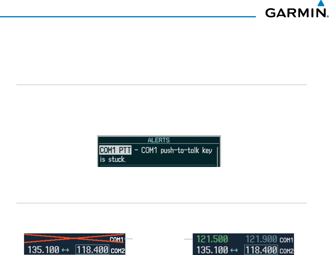
190-00928-04 Rev. A
Garmin G1000 Pilot’s Guide for the Beechcraft 200/B200 Series
148
AUDIO PANEL AND CNS
4.7 ABNORMAL OPERATION
Abnormal operation of the G1000 includes equipment failures of the G1000 components and failure of
associated equipment, including switches and external devices.
STUCK MICROPHONE
If the push-to-talk (PTT) Key becomes stuck, the COM transmitter stops transmitting after 35 seconds of
continuous operation. An alert appears on the PFD to advise the crew of a stuck microphone.
The
COM1 MIC
or
COM2 MIC
Key Annunciator on the Audio Panel flashes as long as the PTT Key remains
stuck.
Figure 4-54 Stuck Microphone Alert
COM TUNING FAILURE
In case of a COM system tuning failure, the emergency frequency (121.500 MHz) is automatically tuned in
the radio in which the tuning failure occurred.
Figure 4-55 COM Tuning Failure
Emergency Channel
Loaded Automatically
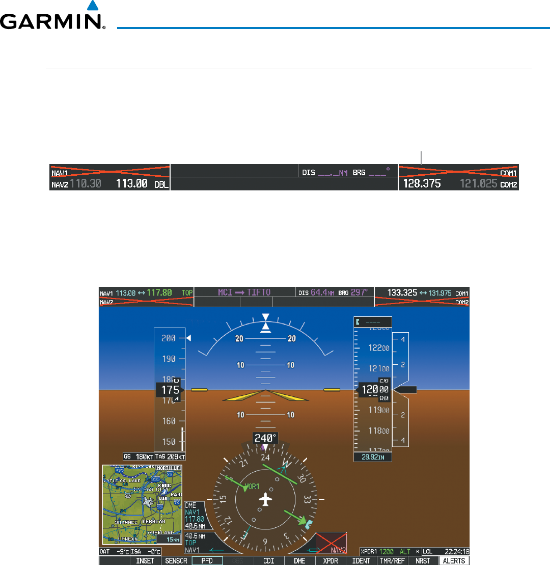
190-00928-04 Rev. A
Garmin G1000 Pilot’s Guide for the Beechcraft 200/B200 Series
149
AUDIO PANEL AND CNS
PFD FAILURE, DUAL SYSTEM
If PFD1 fails, COM1 and NAV1 display a red X on both remaining displays. NAV1 is unavailable. COM1
automatically tunes 121.500 MHz, but the frequency is not shown. The COM1 emergency frequency is available
to both the copilot and pilot.
Figure 4-56 Frequency Section of PFD2 Display after PFD1 Failure
Emergency Channel
Loaded Automatically
If PFD2 fails, COM2 and NAV2 display a red X on the remaining PFD display. NAV2 is unavailable. COM2
tunes 121.500 MHz, but the frequency is not shown. The COM2 emergency frequency is available to both the
copilot and pilot.
Figure 4-57 PFD1 Display after PFD2 Failure
190-00928-04 Rev. A
Garmin G1000 Pilot’s Guide for the Beechcraft 200/B200 Series
150
AUDIO PANEL AND CNS
AUDIO PANEL FAIL-SAFE OPERATION
If there is a failure of both Audio Panels, a fail-safe circuit connects the pilot’s headset and microphone directly
to the COM1 transceiver and the copilot’s headset directly to the COM2 transceiver. Audio is not available on
the speakers.
If there is a failure of one Audio Panel, the remaining one does not have access to the others side’s COM and
NAV. For example, if the pilot side Audio Panel fails, the copilot side Audio Panel has access to all the radios
except for COM1 and NAV1.
REVERSIONARY MODE
The red DISPLAY BACKUP Button selects the PFD/MFD Reversionary Mode. See the System Overview
Section for more information on Reversionary Mode.
Figure 4-58 Reversionary Mode Button

190-00928-04 Rev. A
Garmin G1000 Pilot’s Guide for the Beechcraft 200/B200 Series
151
FLIGHT MANAGEMENT
SECTION 5 FLIGHT MANAGEMENT
5.1 INTRODUCTION
The G1000 is an integrated flight, engine, communication, navigation and surveillance system. This section of
the Pilot’s Guide explains flight management using the G1000.
The most prominent part of the G1000 are the three full color displays: two Primary Flight Displays (PFD) and
a Multi Function Display (MFD). The information to successfully navigate the aircraft using the GPS sensors is
displayed on the PFD and the MFD. See examples in the Figure 5-1 and Figure 5-2. Detailed descriptions of GPS
navigation functions are discussed later in this section.
A brief description of the GPS navigation data on the PFD and MFD follows.
Navigation mode indicates which sensor is providing the course data (e.g., GPS, VOR) and the flight plan
phase (e.g., Departure (DPRT), Terminal (TERM), Enroute (ENR), Oceanic (OCN), Approach (LNAV, LNAV+V, L/
VNAV, LP, LP+V, LPV), or Missed Approach (MAPR)). L/VNAV, LP, LP+V, and LPV approach service levels are only
available with SBAS. L/VNAV will be flown as Baro VNAV when SBAS is not available.
The Inset Map is a small version of the MFD Navigation Map and can be displayed in the lower left corner of
the PFD. When the system is in reversionary mode, the Inset Map is displayed in the lower right corner. The
Inset Map is displayed by pressing the INSET Softkey. Pressing the INSET Softkey again, then pressing the OFF
Softkey removes the Inset Map.
The Navigation Map displays aviation data (e.g., airports, VORs, airways, airspaces), geographic data (e.g.,
cities, lakes, highways, borders), topographic data (map shading indicating elevation), and hazard data (e.g.,
traffic, terrain, weather). The amount of displayed data can be reduced by selecting the DCLTR Softkey. The
Navigation Map can be oriented four different ways: North Up (NORTH UP), Track Up (TRK UP), Desired Track
Up (DTK UP), or Heading Up (HDG UP).
An aircraft icon is placed on the Navigation Map at the location corresponding to the calculated present position.
The aircraft position and the flight plan legs are accurately based on GPS calculations. The basemap upon which
these are placed are from a source with less resolution, therefore the relative position of the aircraft to map features
is not exact. The leg of the active flight plan currently being flown is shown as a magenta line on the navigation
map. The other legs are shown in white.
There are 28 different map ranges available, from 500 feet to 2000 nm. The current range is indicated in the
lower right corner of the map and represents the top-to-bottom distance covered by the map. To change the map
range on any map, turn the Joystick counter-clockwise to zoom in ( -, decreasing), or clockwise to zoom out (+,
increasing).
The Direct-to Window, the Flight Plan Window, the Procedures Window, and the Nearest Airports Window
can be displayed in the lower right corner of the PFD. Details of these windows are discussed in detail later in
the section.
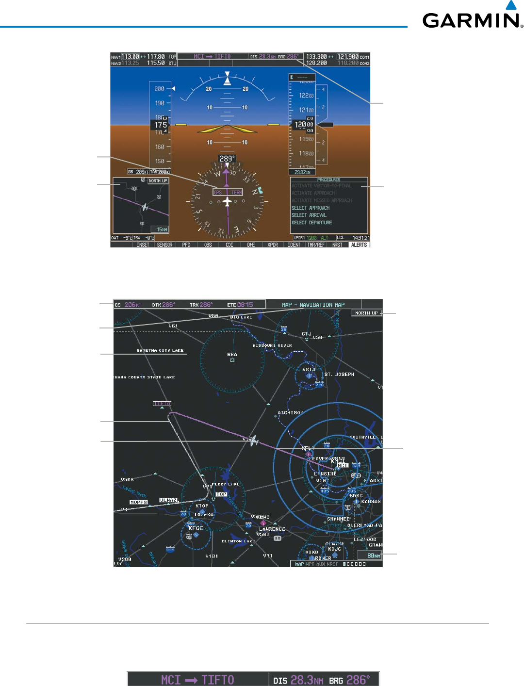
Garmin G1000 Pilot’s Guide for the Beechcraft 200/B200 Series
190-00928-04 Rev. A152
FLIGHT MANAGEMENT
Figure 5-1 GPS Navigation Information on the PFD
Location of:
- Direct To Window
- Flight Plan Window
- Procedures Window
- Nearest Airports Window
Inset Map
Navigation Status Box
Navigation Mode
Figure 5-2 GPS Navigation Information on the MFD Navigation Page
Active Flight Plan Leg
Navigation Map
- Aviation Data
- Geographic Data
- Topographic Data
- Hazard Data
Navigation Status Box
Aircraft Icon
at Present Position
Navigation Page Title
Map Range
Map Orientation
Flight Plan Leg
NAVIGATION STATUS BOX
The Navigation Status Box located at the top of the PFD contains two fields displaying the following
information:
PFD Navigation Status Box
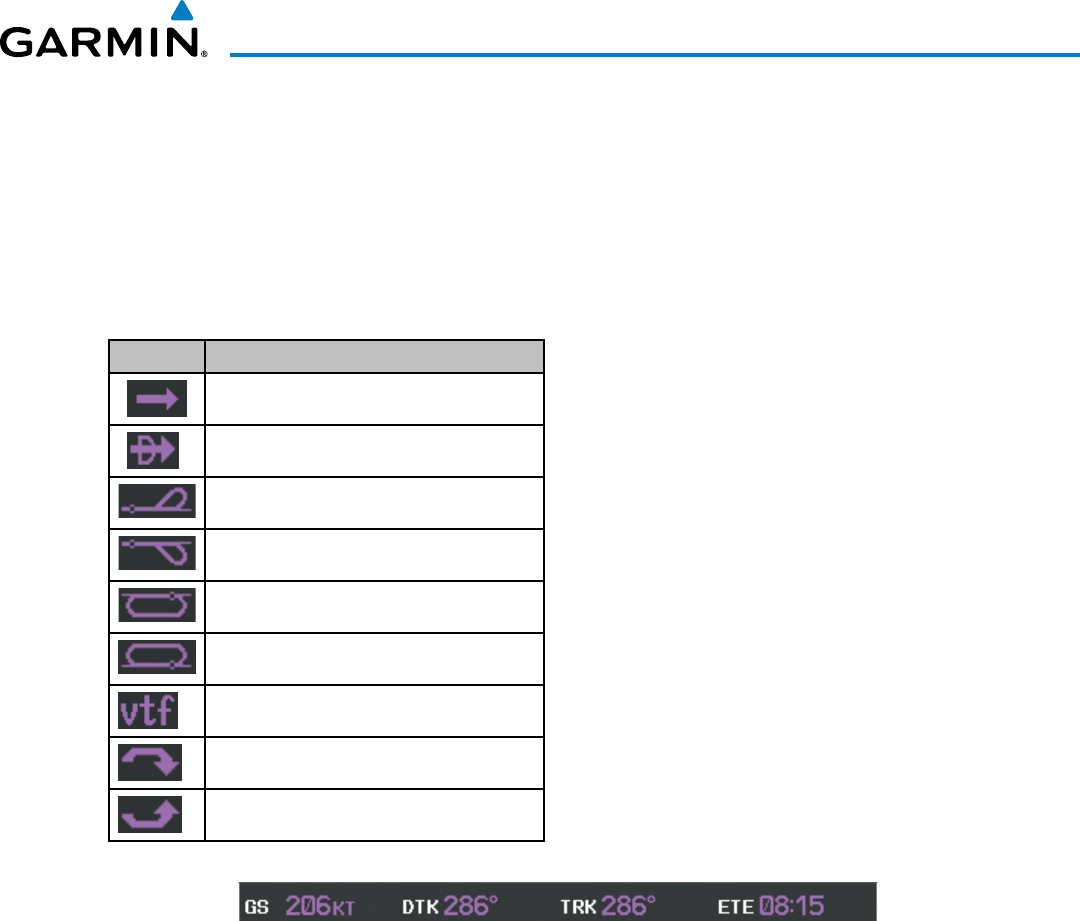
190-00928-04 Rev. A
Garmin G1000 Pilot’s Guide for the Beechcraft 200/B200 Series
153
FLIGHT MANAGEMENT
• Active flight plan leg (e.g., ‘D-> KICT’ or ‘KIXD ->
KCOS’) or flight plan annunciations (e.g., ‘Turn
right to 021˚ in 8 seconds’)
• Distance (DIS) and Bearing (BRG) to the next
waypoint or flight plan annunciations (e.g., ‘TOD
within 1 minute’)
The symbols used in the PFD status bar are:
Symbol Description
Active Leg
Direct-to
Right Procedure Turn
Left Procedure Turn
Right Holding Pattern
Left Holding Pattern
Vector to Final
Right DME Arc
Left DME Arc
The Navigation Status Box located at the top of the
MFD contains four data fields, each displaying one of
the following items:
• Bearing (BRG)
• Distance (DIS)
• Desired Track (DTK)
• Endurance (END)
• Enroute Safe Altitude (ESA)
• Estimated Time of Arrival (ETA)
• Estimated Time Enroute (ETE)
• Fuel on Board (FOB)
• Fuel over Destination (FOD)
• Ground Speed (GS)
• Minimum Safe Altitude (MSA)
• True Air Speed (TAS)
• Track Angle Error (TKE)
• Track (TRK)
• Vertical Speed Required (VSR)
• Crosstrack Error (XTK)
MFD Navigation Status Box
The navigation information displayed in the four data fields can be selected on the MFD Data Bar Fields Box
on the AUX - System Setup Page. The default selections (in order left to right) are GS, DTK, TRK, and ETE.
Changing a field in the MFD Navigation Status Box:
1) Select the System Setup Page.
2) Press the FMS Knob momentarily to activate the flashing cursor.
3) Turn the large FMS Knob to highlight the desired field number in the MFD Data Bar Fields Box.
4) Turn the small FMS Knob to display and scroll through the data options list.
5) Select the desired data.
6) Press the ENT Key. Selecting the DFLTS Softkey returns all fields to the default setting.
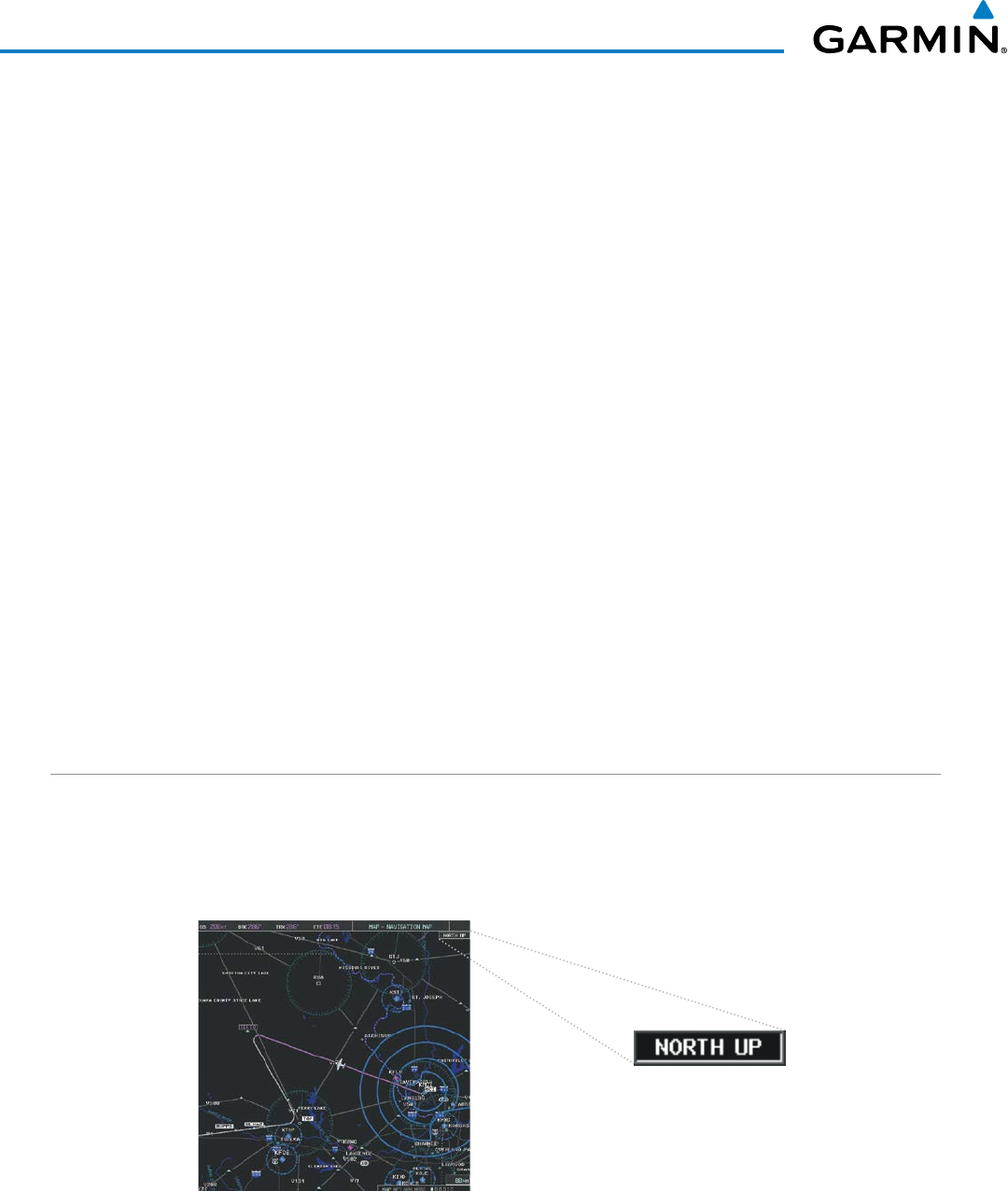
Garmin G1000 Pilot’s Guide for the Beechcraft 200/B200 Series
190-00928-04 Rev. A154
FLIGHT MANAGEMENT
5.2 USING MAP DISPLAYS
Map displays are used extensively in the G1000 to provide situational awareness in flight. Most G1000 maps
can display the following information:
• Airports, NAVAIDs, airspaces, airways, land data
(highways, cities, lakes, rivers, borders, etc.) with
names
• Map Pointer information (distance and bearing to
pointer, location of pointer, name, and other pertinent
information)
• Map range
• Wind direction and speed
• Map orientation
• Icons for enabled map features
• Aircraft icon (representing present position)
• Nav range ring
• Fuel range ring
• Flight plan legs
• User waypoints
• Track vector
• Topography scale
• Topography data
• Obstacle data
MAP ORIENTATION
Maps are shown in one of four different orientation options, allowing flexibility in determining aircraft
position relative to other items on the map (north up) or for determining where map items are relative to where
the aircraft is going (track up, desired track up, or heading up). The map orientation is shown in the upper
right corner of the map.
Figure 5-3 Map Orientation
• North up (NORTH UP) aligns the top of the map display to north (default setting).
• Track up (TRK UP) aligns the top of the map display to the current ground track.
• All Map Group Pages (MAP)
• All Waypoint Group Pages (WPT)
• AUX - Trip Planning
• All Nearest Group Pages (NRST)
• Flight Plan Pages (FPL)
• Direct-to Window
• PFD Inset Map
• Procedure Loading Pages
The information in this section applies to the following maps unless otherwise noted:
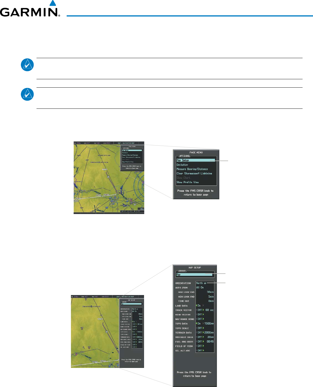
190-00928-04 Rev. A
Garmin G1000 Pilot’s Guide for the Beechcraft 200/B200 Series
155
FLIGHT MANAGEMENT
• Desired track up (DTK UP) aligns the top of the map display to the desired course.
• Heading up (HDG UP) aligns the top of the map display to the current aircraft heading.
NOTE: When panning or reviewing active flight plan legs in a non-North Up orientation, the map does not
show the map orientation nor the wind direction and speed.
NOTE: Map orientation can only be changed on the Navigation Map Page. Any other displays that show
navigation data reflect the orientation selected for the Navigation Map Page.
Changing the Navigation Map orientation:
1) With the Navigation Map Page displayed, press the MENU Key. The cursor flashes on the ‘Map Setup’ option.
Figure 5-4 Navigation Map Page Menu Window
Map Setup
Selection
2) Press the ENT Key to display the Map Setup Window.
3) Turn the large FMS Knob, or press the ENT Key once, to select the ‘ORIENTATION’ field.
Figure 5-5 Map Setup Menu Window - Map Group
Orientation Field
Map Group Selection
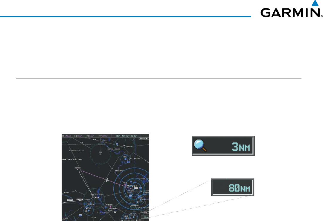
Garmin G1000 Pilot’s Guide for the Beechcraft 200/B200 Series
190-00928-04 Rev. A156
FLIGHT MANAGEMENT
4) Turn the small FMS Knob to select the desired orientation.
5) Press the ENT Key to select the new orientation.
6) Press the FMS Knob to return to the base page.
MAP RANGE
There are 28 different map ranges available, from 500 feet to 2000 nm. The current range is indicated in
the lower right corner of the map and represents the top-to-bottom distance covered by the map. When the
map range is decreased to a point that exceeds the capability of the G1000 to accurately represent the map,
a magnifying glass icon is shown to the left of the map range. To change the map range turn the Joystick
counter-clockwise to decrease the range, or clockwise to increase the range.
Figure 5-6 Map Range
Range Overzoom
AUTO ZOOM
Auto zoom allows the G1000 to change the map display range to the smallest range clearly showing the
active waypoint. Auto zoom can be overridden by adjusting the range with the Joystick, and remains until
the active waypoint changes, a terrain or traffic alert occurs, the aircraft takes off, or the manual override times
out (timer set on Map Setup Window).
If a terrain caution or warning occurs, any map page displaying TAWS/TERRAIN data automatically adjusts
to the smallest map range clearly showing the highest priority alert. If a new traffic advisory alert occurs, any
map page capable of displaying traffic advisory alerts automatically adjusts to the smallest map range clearly
showing the traffic advisory. When terrain or traffic alerts clear, the map returns to the previous auto zoom
range based on the active waypoint.
The auto zoom function can be turned on or off independently for the PFDs and MFD. Control of the
ranges at which the auto zoom occurs is done by setting the minimum and maximum ‘look forward’ times
(set on the Map Setup Window for the Map Group). These settings determine the minimum and maximum
distance to display based upon the aircraft’s ground speed.
• Waypoints that are long distances apart cause the map range to increase to a point where many details on
the map are decluttered. If this is not acceptable, lower the maximum look ahead time to a value that limits
the auto zoom to an acceptable range.
• Waypoints that are very short distances apart cause the map range to decrease to a point where situational
awareness may not be what is desired. Increase the minimum look ahead time to a value that limits the auto
zoom to a minimum range that provides acceptable situational awareness.
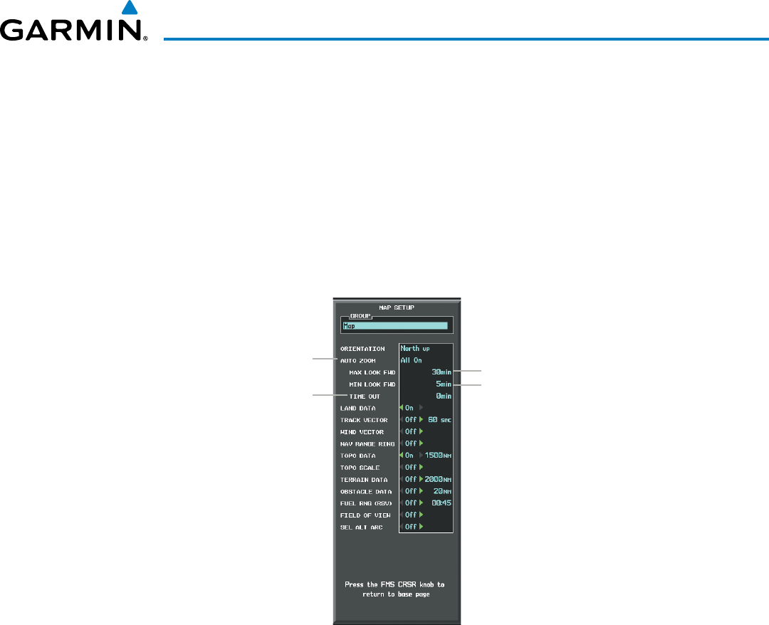
190-00928-04 Rev. A
Garmin G1000 Pilot’s Guide for the Beechcraft 200/B200 Series
157
FLIGHT MANAGEMENT
• Flight plans that have a combination of long and short legs cause the range to increase and decrease as
waypoints sequence. To avoid this, auto zoom can be disabled or the maximum/minimum times can be
adjusted.
• The ‘time out’ time (configurable on the Map Setup Page for the Map Group) determines how long auto
zoom is overridden by a manual adjustment of the range knob. At the expiration of this time, the auto
zoom range is restored. Setting the ‘time out’ value to zero causes the manual override to never time out.
• When the maximum ‘look forward’ time is set to zero, the upper limit becomes the maximum range available
(2000 nm).
• When the minimum ‘look forward’ time is set to zero, the lower limit becomes 1.5 nm.
Figure 5-7 Map Setup Menu Window - Map Group, Auto Zoom
Auto Zoom:
Off, MFD Only, PFD Only, All On
Manual Range Override
Expiration Time
Maximum Look Forward Time
Minimum Look Forward Time
Configuring automatic zoom:
1) Press the MENU Key with the Navigation Map Page displayed. The cursor flashes on the ‘Map Setup’ option.
2) Press the ENT Key. The Map Setup Menu is displayed.
3) Select the ‘Map’ group.
4) Press the ENT Key.
5) Highlight the ‘AUTO ZOOM’ field.
6) Select ‘Off’, ‘MFD Only’, ‘PFD Only’, or ‘ALL On’.
7) Press the ENT Key to accept the selected option. The flashing cursor highlights the ‘MAX LOOK FWD’ field.
Times are from zero to 999 minutes.
8) Use the FMS Knobs to set the time. Press the ENT Key.
9) Repeat step 8 for ‘MIN LOOK FWD’ (zero to 99 minutes) and ‘TIME OUT’ (zero to 99 minutes).
10) Press the FMS Knob to return to the Navigation Map Page.
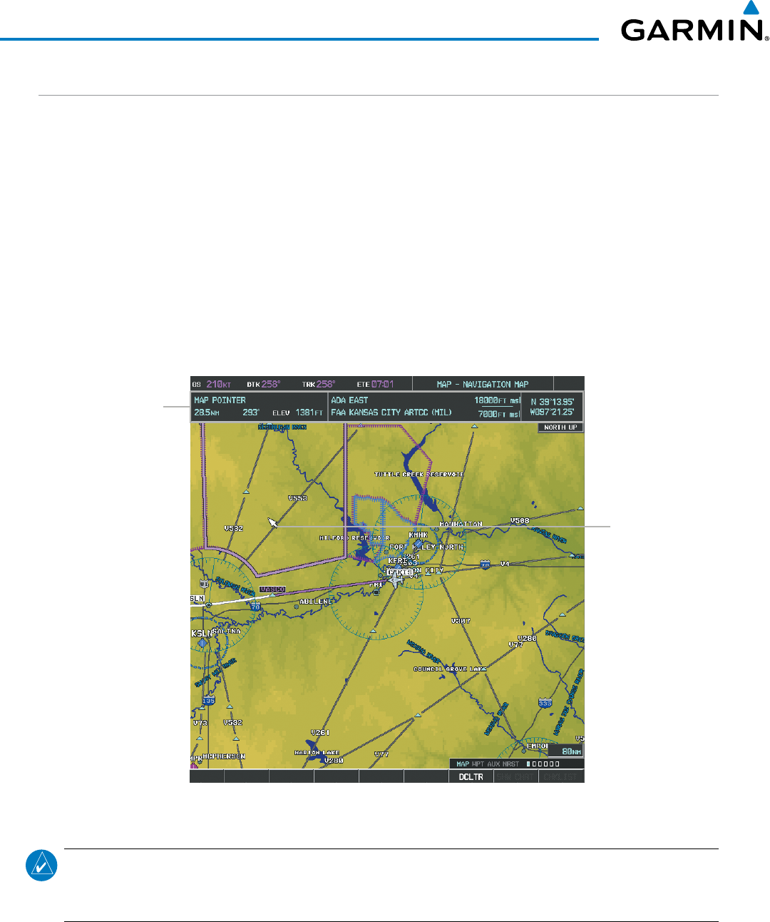
Garmin G1000 Pilot’s Guide for the Beechcraft 200/B200 Series
190-00928-04 Rev. A158
FLIGHT MANAGEMENT
MAP PANNING
Map panning allows the pilot to:
• View parts of the map outside the displayed range without adjusting the map range
• Highlight and select locations on the map
• Review information for a selected airport, NAVAID or user waypoint
• Designate locations for use in flight planning
• View airspace and airway information
When the panning function is selected by pressing the Joystick, the Map Pointer flashes on the map display.
A window also appears at the top of the map display showing the latitude/longitude position of the pointer,
the bearing and distance to the pointer from the aircraft’s present position, and the elevation of the land at the
position of the pointer.
Figure 5-8 Navigation Map - Map Pointer Activated
Map Pointer
Map Pointer Information
NOTE: The map is normally centered on the aircraft’s position. If the map has been panned and there has
been no pointer movement for about 60 seconds, the map reverts back to centered on the aircraft position
and the flashing pointer is removed.
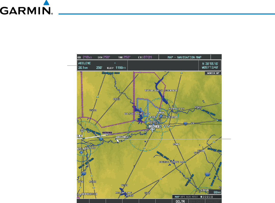
190-00928-04 Rev. A
Garmin G1000 Pilot’s Guide for the Beechcraft 200/B200 Series
159
FLIGHT MANAGEMENT
When the Map Pointer is placed on an object, the name of the object is highlighted (even if the name was
not originally displayed on the map). When any map feature or object is selected on the map display, pertinent
information is displayed.
Figure 5-9 Navigation Map - Map Pointer on Point of Interest
Map Pointer on
POI
Information about Point
of Interest
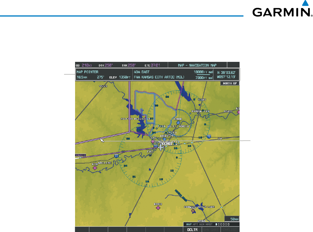
Garmin G1000 Pilot’s Guide for the Beechcraft 200/B200 Series
190-00928-04 Rev. A160
FLIGHT MANAGEMENT
When the Map Pointer crosses an airspace boundary, the boundary is highlighted and airspace information
is shown at the top of the display. The information includes the name and class of airspace, the ceiling in feet
above Mean Sea Level (MSL), and the floor in feet MSL.
Figure 5-10 Navigation Map - Map Pointer on Airspace
Map Pointer on
Airspace
Information about
Airspace
Panning the map:
1) Press the Joystick to display the Map Pointer.
2) Move the Joystick to move the Map Pointer around the map.
3) Press the Joystick to remove the Map Pointer and recenter the map on the aircraft’s current position.
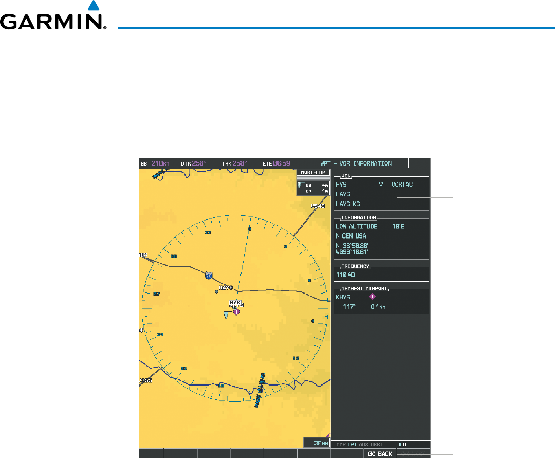
190-00928-04 Rev. A
Garmin G1000 Pilot’s Guide for the Beechcraft 200/B200 Series
161
FLIGHT MANAGEMENT
Reviewing information for an airport, NAVAID, or user waypoint:
1) Place the Map Pointer on a waypoint.
2) Press the ENT Key to display the Waypoint Information Page for the selected waypoint.
3) Select the GO BACK Softkey, the CLR Key, or the ENT Key to exit the Waypoint Information Page and return to
the Navigation Map showing the selected waypoint.
Figure 5-11 Navigation Map - Information Window - NAVAID
NAVAID
Information
GO BACK Softkey
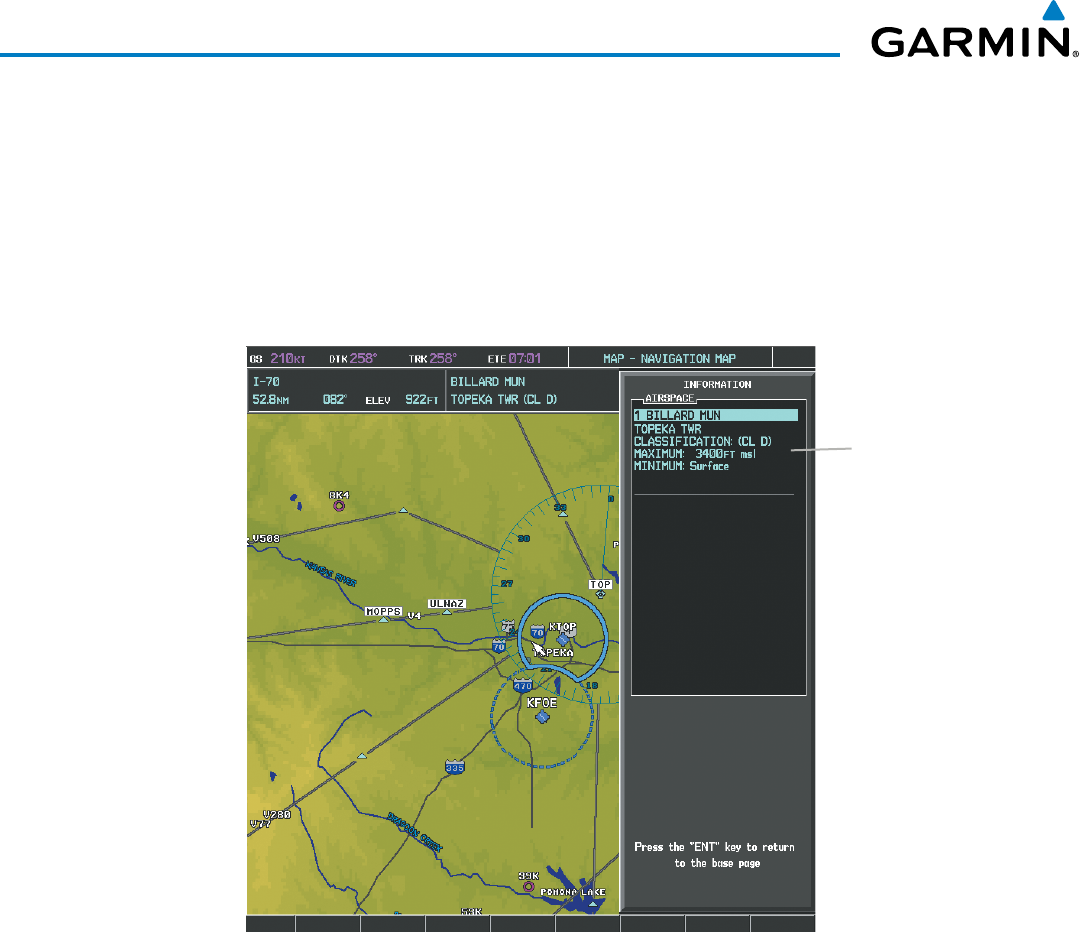
Garmin G1000 Pilot’s Guide for the Beechcraft 200/B200 Series
190-00928-04 Rev. A162
FLIGHT MANAGEMENT
Viewing airspace information for a special-use or controlled airspace:
1) Place the Map Pointer on an open area within the boundaries of an airspace.
2) Press the ENT Key to display an options menu.
3) ‘Review Airspaces?’ should already be highlighted, if not select it. Press the ENT Key to display the Airspace
Information Page for the selected airspace.
4) Press the CLR or ENT Key to exit the Airspace Information Page.
Figure 5-12 Navigation Map - Information Window - Airspace
Airspace
Information
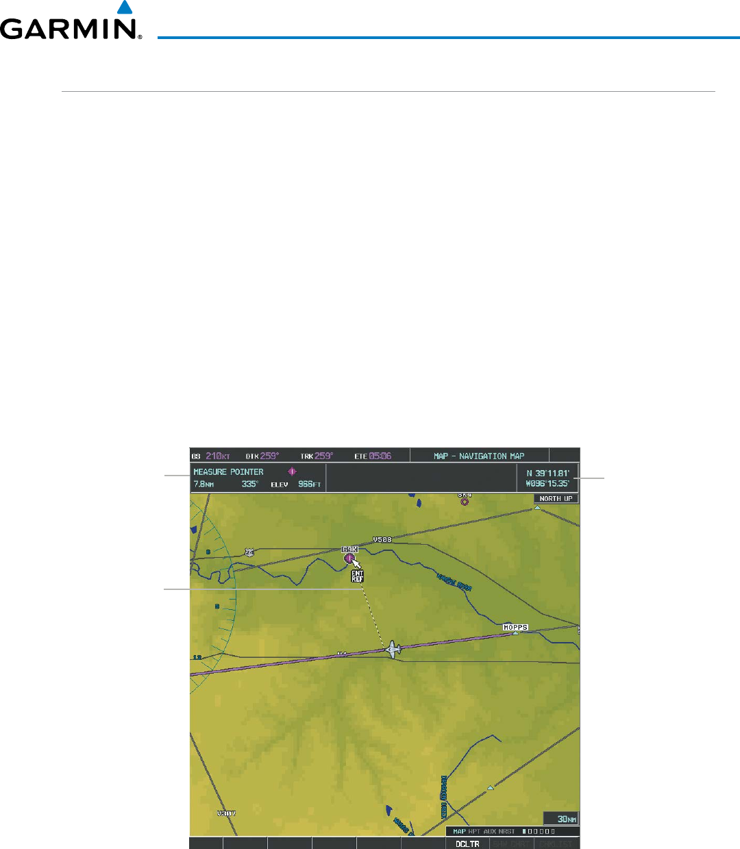
190-00928-04 Rev. A
Garmin G1000 Pilot’s Guide for the Beechcraft 200/B200 Series
163
FLIGHT MANAGEMENT
MEASURING BEARING AND DISTANCE
Distance and bearing from the aircraft’s present position to any point on the viewable navigation map may be
calculated using the ‘Measure Bearing and Distance’ selection from Navigation Map page menu. The bearing
and distance tool displays a dashed Measurement Line and a Measure Pointer to aid in graphically identifying
points with which to measure. Lat/Long, distance and elevation data for the Measure Pointer is provided in a
window at the top of the navigation map.
Measuring bearing and distance between any two points:
1) Press the MENU Key (with the Navigation Map Page displayed).
2) Highlight the ‘Measure Bearing/Distance’ field.
3) Press the ENT Key. A Measure Pointer is displayed on the map at the aircraft’s present position.
4) Move the Joystick to place the reference pointer at the desired location. The bearing and distance are displayed
at the top of the map. Elevation at the current pointer position is also displayed. Pressing the ENT Key changes
the starting point for measuring.
5) To exit the Measure Bearing/Distance option, press the Joystick; or select ‘Stop Measuring’ from the Page
Menu and press the ENT Key.
Figure 5-13 Navigation Map - Measuring Bearing and Distance
Pointer Lat/Long
Measurement
Information
Measurement Line
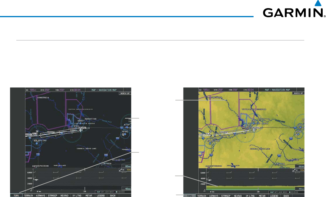
Garmin G1000 Pilot’s Guide for the Beechcraft 200/B200 Series
190-00928-04 Rev. A164
FLIGHT MANAGEMENT
TOPOGRAPHY
All navigation maps can display various shades of topography colors representing land elevation, similar
to aviation sectional charts. Topographic data can be displayed or removed as described in the following
procedures. Topographic data can also be displayed on the selectable profile map at the bottom of the navigation
map (the profile map is not available if TAWS-A is configured).
Navigation Map
Black Background
TOPO Off
Figure 5-14 Navigation Map - Topographic Data
TOPO Softkey
Enabled
Navigation Map
Topographic Data
TOPO On
TOPO Softkey
Not Enabled
Topographic Data
on Profile Map
Displaying/removing topographic data on all pages displaying navigation maps:
1) Select the MAP Softkey (the INSET Softkey for the PFD Inset Map).
2) Select the TOPO Softkey.
3) Select the TOPO Softkey again to remove topographic data from the Navigation Map. When topographic data
is removed from the page, all navigation data is presented on a black background.
Displaying/removing topographic data (TOPO DATA) using the Navigation Map Page Menu:
1) Press the MENU Key with the Navigation Map Page displayed. The cursor flashes on the ‘Map Setup’ option.
2) Press the ENT Key. The Map Setup Menu is displayed.
3) Select the ‘Map’ group.
4) Press the ENT Key.
5) Highlight the ‘TOPO DATA’ field.
6) Select ‘On’ or ‘Off’.
7) Press the FMS Knob to return to the Navigation Map Page.
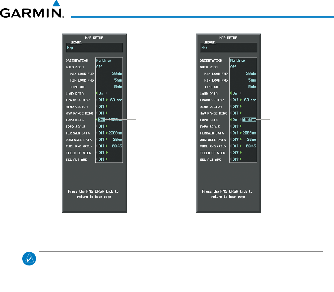
190-00928-04 Rev. A
Garmin G1000 Pilot’s Guide for the Beechcraft 200/B200 Series
165
FLIGHT MANAGEMENT
Figure 5-15 Navigation Map Setup Menu - TOPO DATA Setup
TOPO DATA
On/Off TOPO DATA
Range
The topographic data range is the maximum map range on which topographic data is displayed.
NOTE: Since the PFD Inset Map is much smaller than the MFD navigation maps, items are removed on the
PFD Inset Map two range levels smaller than the range selected in the Map Setup pages (e.g., a setting
of 100 nm removes the item at ranges above 100 nm on MFD navigation maps, while the PFD Inset Map
removes the same item at 50 nm).
Selecting a topographical data range (TOPO DATA):
1) Press the MENU Key with the Navigation Map Page displayed. The cursor flashes on the ‘Map Setup’ option.
2) Press the ENT Key. The Map Setup Menu is displayed.
3) Select the ‘Map’ group.
4) Press the ENT Key.
5) Highlight the ‘TOPO DATA’ range field. TOPO ranges are from 500 ft to 2000 nm.
6) To change the TOPO range setting, turn the small FMS Knob to display the range list.
7) Select the desired range using the small FMS Knob.
8) Press the ENT Key.
9) Press the FMS Knob to return to the Navigation Map Page.
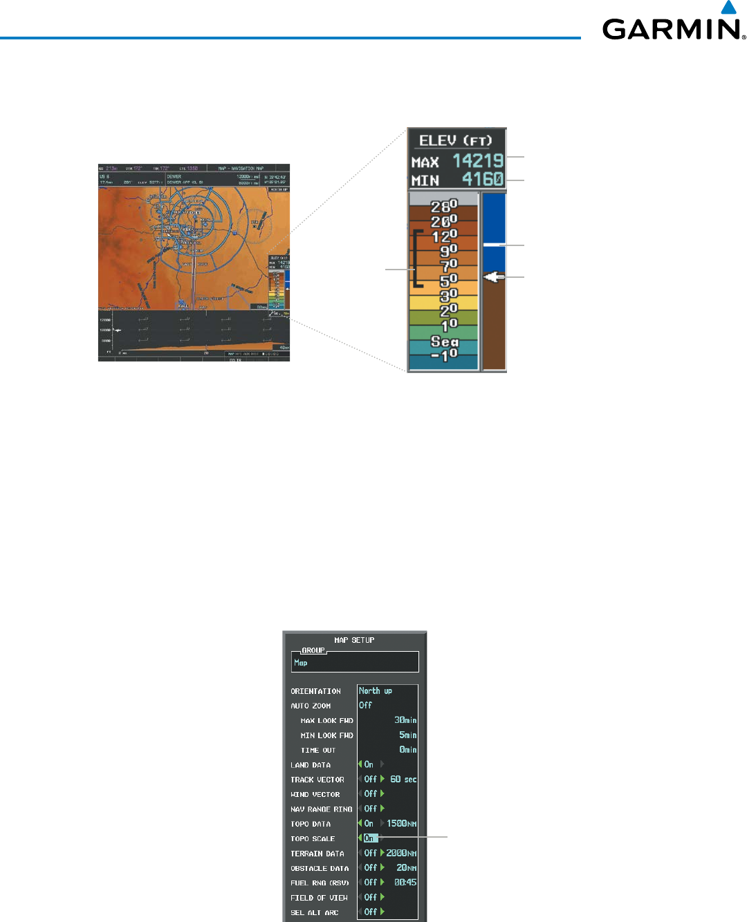
Garmin G1000 Pilot’s Guide for the Beechcraft 200/B200 Series
190-00928-04 Rev. A166
FLIGHT MANAGEMENT
In addition, the Navigation Map can display a topographic scale (located in the lower right hand side of the
map) showing a scale of the terrain elevation and current elevation values.
Figure 5-16 Navigation Map - TOPO SCALE
Maximum Displayed Elevation
Minimum Displayed Elevation
Aircraft Altitude (MSL)
Ground Elevation at Map Pointer
Location (only visible when Map
Pointer is displayed)
Range of
Displayed
Elevations
Displaying/removing the topographic scale (TOPO SCALE):
1) Press the MENU Key with the Navigation Map Page displayed. The cursor flashes on the ‘Map Setup’ option.
2) Press the ENT Key. The Map Setup Menu is displayed.
3) Select the ‘Map’ group and select the ENT Key.
4) Highlight the ‘TOPO SCALE’ field.
5) Select ‘On’ or ‘Off’.
6) Press the FMS Knob to return to the Navigation Map Page.
Figure 5-17 Navigation Map Setup Menu - TOPO SCALE Setup
TOPO SCALE
On/Off
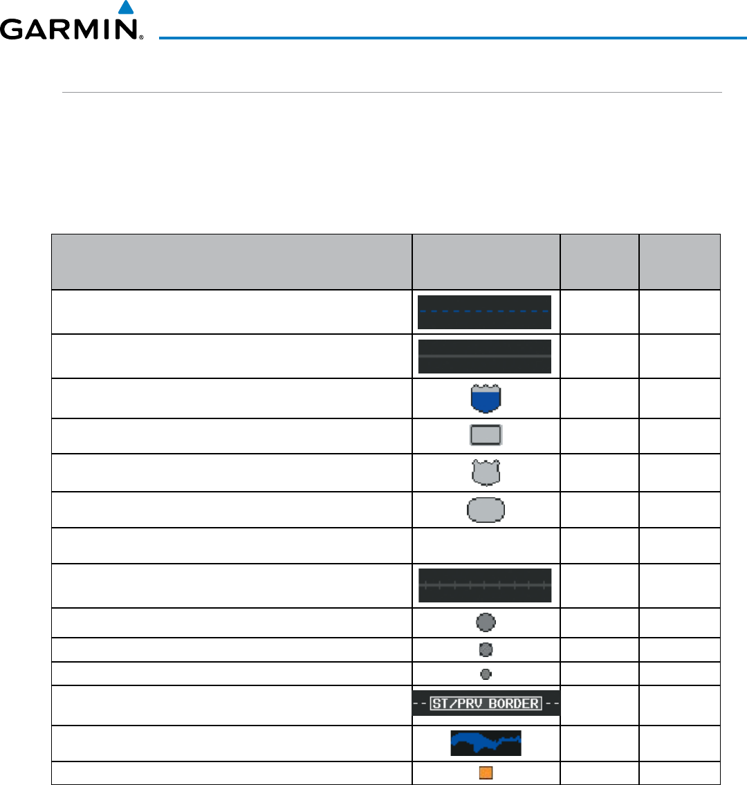
190-00928-04 Rev. A
Garmin G1000 Pilot’s Guide for the Beechcraft 200/B200 Series
167
FLIGHT MANAGEMENT
MAP SYMBOLS
This section discusses the types of land and aviation symbols that can be displayed. Each listed type of symbol
can be turned on or off, and the maximum range to display each symbol can be set. The decluttering of the
symbols from the map using the DCLTR Softkey is also discussed.
LAND SYMBOLS
The following items are configured on the land menu:
Land Symbols
(Text label size can be None, Small, Medium (Med), or Large
(Lrg))
Symbol Default
Range (nm)
Maximum
Range (nm)
Latitude/Longitude (LAT/LON) Off 2000
Highways and Roads
Interstate Highway (FREEWAY) 300 800
International Highway (FREEWAY) 300 800
US Highway (NATIONAL HWY) 30 80
State Highway (LOCAL HWY) 15 30
Local Road (LOCAL ROAD) N/A 8 15
Railroads (RAILROAD) 15 30
LARGE CITY (> 200,000) 800 1500
MEDIUM CITY (> 50,000) 100 200
SMALL CITY (> 5,000) 20 50
States and Provinces (STATE/PROV) 800 1500
Rivers and Lakes (RIVER/LAKE) 200 500
USER WAYPOINT 150 300
Table 5-1 Land Symbol Information
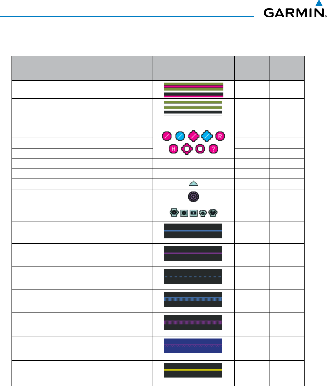
Garmin G1000 Pilot’s Guide for the Beechcraft 200/B200 Series
190-00928-04 Rev. A168
FLIGHT MANAGEMENT
AVIATION SYMBOLS
The following items are configured on the aviation menu:
Aviation Symbols
(Text label size can be None, Small, Medium (Med),
or Large (Lrg))
Symbol Default
Range (nm)
Maximum
Range (nm)
Active Flight Plan Leg (ACTIVE FPL) 2000 2000
Non-active Flight Plan Leg (ACTIVE FPL) 2000 2000
Active Flight Plan Waypoint (ACTIVE FPL WPT) See Airports, NAVAIDs 2000 2000
Large Airports (LARGE APT)
200 500
Medium Airports (MEDIUM APT) 150 300
Small Airports (SMALL APT) 50 100
Taxiways (SAFETAXI) See Additional Features 3 20
Runway Extension (RWY EXTENSION) N/A Off 100
Intersection (INT WAYPOINT) 15 30
Non-directional Beacon (NDB WAYPOINT) 15 30
VOR (VOR WAYPOINT) 150 300
Class B Airspace/TMA (CLASS B/TMA) 200 500
Class C Airspace/TCA (CLASS C/TCA) 200 500
Class D Airspace (CLASS D) 150 300
Restricted Area (RESTRICTED) 200 500
Military Operations Area [MOA(MILITARY)] 200 500
Other/Air Defense Interdiction Zone (OTHER/ADIZ) 200 500
Temporary Flight Restriction (TFR) 500 2000
Table 5-2 Aviation Symbol Information
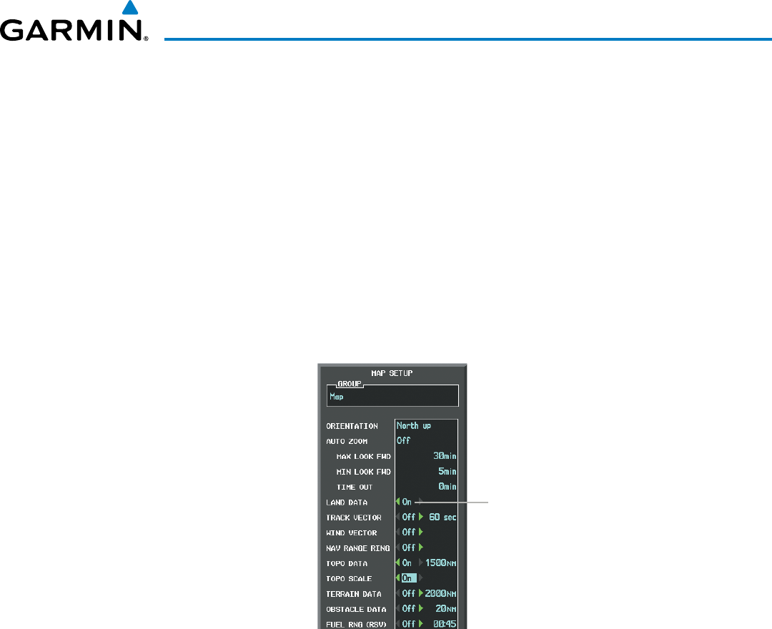
190-00928-04 Rev. A
Garmin G1000 Pilot’s Guide for the Beechcraft 200/B200 Series
169
FLIGHT MANAGEMENT
SYMBOL SETUP
All pages with maps can display land symbols (roads, lakes, borders, etc). Land symbols can be removed
totally (turned off).
Displaying/removing all land symbols:
1) Press the MENU Key with the Navigation Map Page displayed. The Page Menu is displayed and the cursor
flashes on the ‘Map Setup’ option.
2) Press the ENT Key. The Map Setup Group Menu is displayed and the cursor flashes on the ‘Map’ option.
3) Highlight the ‘LAND DATA’ field.
4) Select ‘On’ or ‘Off’.
5) Press the FMS Knob to return to the Navigation Map Page.
Figure 5-18 Navigation Map Setup Menu - LAND DATA Setup
LAND DATA
On/Off
The label size (TEXT) sets the size at which labels appear on the display (none, small, medium, and large).
The range (RNG) sets the maximum range at which items appear on the display.
Selecting a ‘Land’ or ‘Aviation’ group item text size and range:
1) Press the MENU Key with the Navigation Map Page displayed. The cursor flashes on the ‘Map Setup’ option.
2) Press the ENT Key. The Map Setup Menu is displayed.
3) Select the ‘Land’ or ‘Aviation’ group.
4) Press the ENT Key. The cursor flashes on the first field.
5) Select the desired land option.
6) Select the desired text size.
7) Press the ENT Key to accept the selected size.
8) Select the desired range.
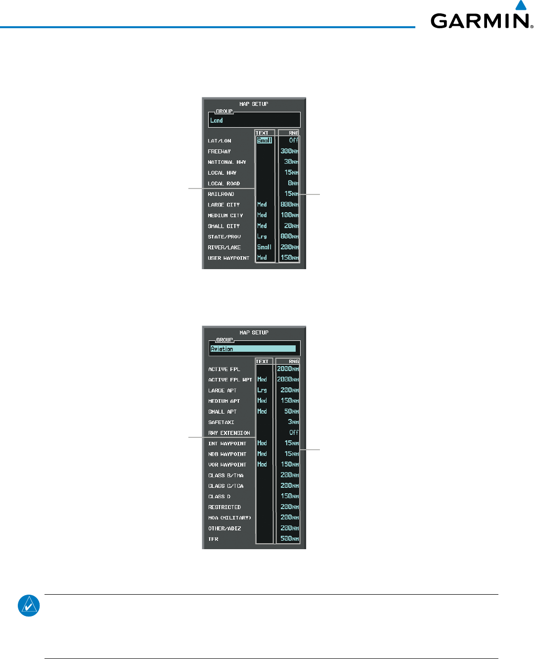
Garmin G1000 Pilot’s Guide for the Beechcraft 200/B200 Series
190-00928-04 Rev. A170
FLIGHT MANAGEMENT
9) Press the ENT Key to accept the selected range.
10) Press the FMS Knob to return to the Navigation Map Page.
Figure 5-19 Navigation Map Setup Menu - LAND GROUP Setup
Maximum Display Range
Text Label Size
(None, Small, Med, or Lrg)
Figure 5-20 Navigation Map Setup Menu - AVIATION GROUP Setup
Maximum Display Range
Text Label Size
(None, Small, Med, or Lrg)
NOTE: Since the PFD Inset Map is much smaller than the MFD navigation maps, items are removed on the
PFD Inset Map two range levels smaller than the range selected in the Map Setup pages (e.g., a setting
of 100 nm removes the item at ranges above 100 nm on MFD navigation maps, while the PFD Inset Map
removes the same item at 50 nm).
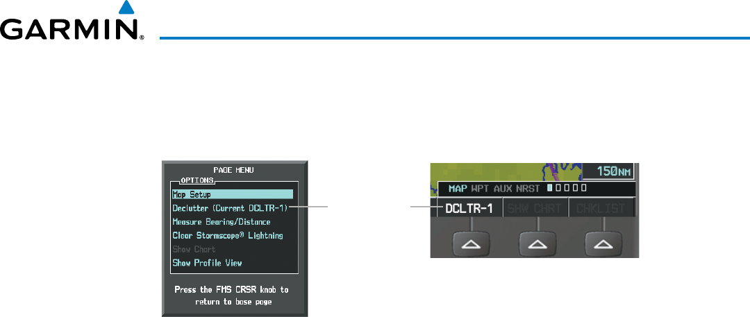
190-00928-04 Rev. A
Garmin G1000 Pilot’s Guide for the Beechcraft 200/B200 Series
171
FLIGHT MANAGEMENT
MAP DECLUTTER
The declutter feature allows the pilot to progressively step through four levels of removing map information.
The declutter level is displayed in the DCLTR Softkey and next to the Declutter Menu Option.
Figure 5-21 Navigation Map - Declutter Level Indications
Declutter Level
Navigation Map Page Menu
DCLTR Softkey
Decluttering the map:
Select the DCLTR Softkey with the Navigation Map Page displayed. The current declutter level is shown. With
each softkey selection, another level of map information is removed.
Or:
1) Press the MENU Key with the Navigation Map Page displayed.
2) Select ‘Declutter’. The current declutter level is shown.
3) Press the ENT Key.
Decluttering the PFD Inset Map:
1) Press the INSET Softkey.
2) Select the DCLTR Softkey. The current declutter level is shown. With each selection, another level of map
information is removed.
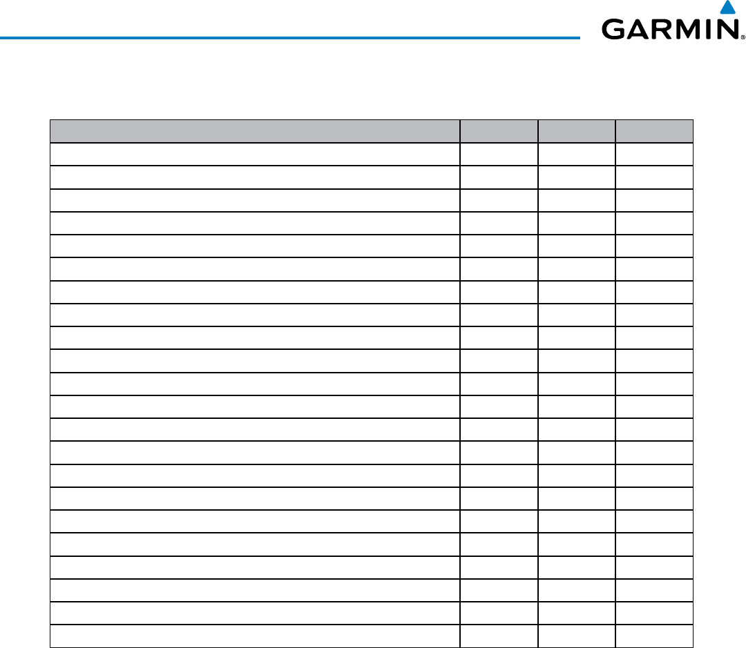
Garmin G1000 Pilot’s Guide for the Beechcraft 200/B200 Series
190-00928-04 Rev. A172
FLIGHT MANAGEMENT
Table 5-3 lists the items that are decluttered at each map detail level. The ‘X’ represents map items
decluttered for each level of detail.
Item Declutter-1 Declutter-2 Least
Data Link Radar Precipitation X
Data Link Lightning X
Graphical METARs X
Airports X
Safe Taxi X
Runway Labels X
TFRs X
Restricted X
MOA (Military) X
User Waypoints X X
Latitude/Longitude Grid X X
NAVAIDs (does not declutter if used to define airway) X X
Intersections (does not declutter if used to define airway) X X
Class B Airspaces/TMA X X
Class C Airspaces/TCA X X
Class D Airspaces X X
Other Airspaces/ADIZ X X
Obstacles X X
Cities X X X
Roads X X X
Railroads X X X
State/Province Boundaries X X X
Table 5-3 Navigation Map Items Decluttered for each Detail Level
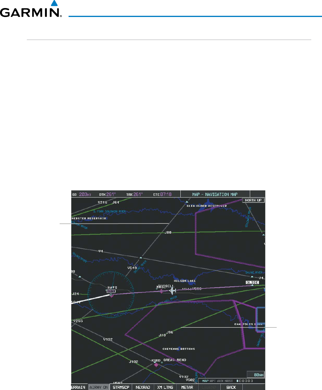
190-00928-04 Rev. A
Garmin G1000 Pilot’s Guide for the Beechcraft 200/B200 Series
173
FLIGHT MANAGEMENT
AIRWAYS
This airways discussion is based upon the North American airway structure. The airway structure in places
other than North America vary by location, etc. and are not discussed in this book. Low Altitude Airways (or
Victor Airways) primarily serve smaller piston-engine, propeller-driven airplanes on shorter routes and at lower
altitudes. Airways are eight nautical miles wide and start 1,200 feet above ground level (AGL) and extend up
to 18,000 feet mean sea level (MSL). Low Altitude Airways are designated with a “V” before the airway number
(hence the name “Victor Airways”) since they run primarily between VORs.
High Altitude Airways (or Jet Routes) primarily serve airliners, jets, turboprops, and turbocharged piston
aircraft operating above 18,000 feet MSL. Jet Routes start at 18,000 feet MSL and extend upward to 45,000 feet
MSL (altitudes above 18,000 feet are called “flight levels” and are described as FL450 for 45,000 feet MSL). Jet
Routes are designated with a “J” before the route number.
Low Altitude Airways are drawn in gray (the same shade used for roads). High Altitude Airways are drawn
in green. When both types of airways are displayed, High Altitude Airways are drawn on top of Low Altitude
Airways.
When airways are selected for display on the map, the airway waypoints (VORs, NDBs and Intersections) are
also displayed.
Figure 5-22 Airways on MFD Navigation Page
Low Altitude
Airway
(Victor Airway)
High Altitude
Airway
(Jet Route)
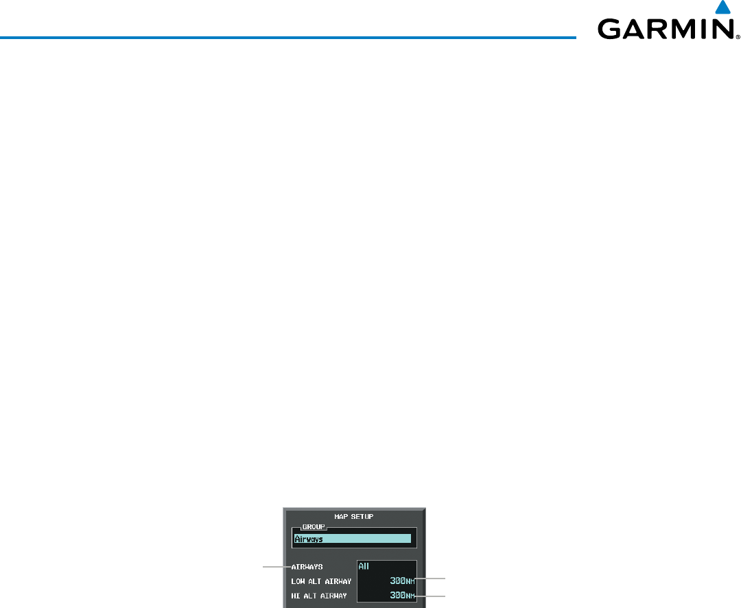
Garmin G1000 Pilot’s Guide for the Beechcraft 200/B200 Series
190-00928-04 Rev. A174
FLIGHT MANAGEMENT
Airways may be displayed on the map at the pilot’s discretion using either a combination of AIRWAYS Softkey
selections, or menu selections using the MENU Key from the Navigation Map Page. The Airway range can also
be programmed to only display Airways on the MFD when the map range is at or below a specific number.
Displaying/removing airways:
1) Select the MAP Softkey.
2) Select the AIRWAYS Softkey. Both High and Low Altitude Airways are displayed (AIRWY ON).
3) Select the softkey again to display Low Altitude Airways only (AIRWY LO).
4) Select the softkey again to display High Altitude Airways only (AIRWY HI).
5) Select the softkey again to remove High Altitude Airways. No airways are displayed (AIRWAYS).
Or:
1) Press the MENU Key with the Navigation Map Page displayed. The cursor flashes on the ‘Map Setup’ option.
2) Press the ENT Key. The Map Setup Menu is displayed.
3) Turn the small FMS Knob to select the ‘Airways’ group, and press the ENT Key.
4) Turn the large FMS Knob to highlight the ‘AIRWAYS’ field.
5) Turn the FMS Knob to select ‘Off’, ‘All’, ‘LO Only’, or ‘HI Only’, and press the ENT Key.
6) Press the FMS Knob to return to the Navigation Map Page.
Figure 5-23 Navigation Map Setup Menu - AIRWAYS Setup
Low Altitude Airway Range
High Altitude Airway Range
Airway Display Selection
Off, All, LO Only, HI Only
The airway range is the maximum map range on which airways are displayed.
Selecting an airway range (LOW ALT AIRWAY or HI ALT AIRWAY):
1) Press the MENU Key with the Navigation Map Page displayed. The cursor flashes on the ‘Map Setup’ option.
2) Press the ENT Key. The Map Setup Menu is displayed.
3) Turn the small FMS Knob to select the ‘Airways’ group, and press the ENT Key.
4) Highlight the ‘LOW ALT AIRWAY’ or ‘HI ALT AIRWAY’ range field.
5) To change the range setting, turn the small FMS Knob to display the range list.
6) Select the desired range using the small FMS Knob.
7) Press the ENT Key.
8) Press the FMS Knob to return to the Navigation Map Page.
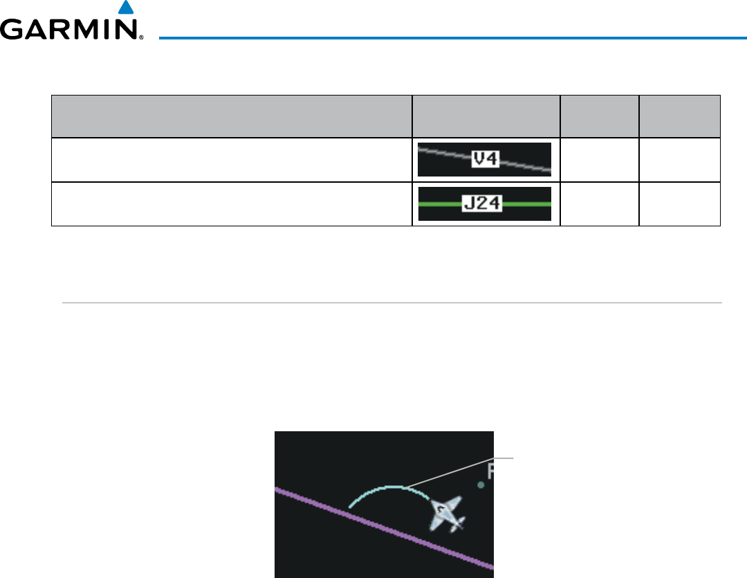
190-00928-04 Rev. A
Garmin G1000 Pilot’s Guide for the Beechcraft 200/B200 Series
175
FLIGHT MANAGEMENT
The following range items are configurable on the airways menu:
Airway Type Symbol Default
Range (nm)
Maximum
Range (nm)
Low Altitude Airway (LOW ALT AIRWAY) 200 500
High Altitude Airway (HI ALT AIRWAY) 300 500
Table 5-4 Airway Range Information
TRACK VECTOR
The Navigation Map can display a track vector that is useful in minimizing track angle error. The track vector
is a solid light blue line segment extended to a predicted location. The track vector look-ahead time is selectable
(30 sec, 60 sec (default), 2 min, 5 min, 10 min, 20 min) and determines the length of the track vector. The track
vector shows up to 90 degrees of a turn for the 30 and 60 second time settings. It is always a straight line for
the 2 min, 5 min, 10 min and 20 min settings.
Figure 5-24 Navigation Map -Track Vector
Track Vector
Displaying/removing the track vector:
1) Press the MENU Key with the Navigation Map Page displayed. The cursor flashes on the ‘Map Setup’ option.
2) Press the ENT Key. The Map Setup Menu is displayed.
3) Select the ‘Map’ group.
4) Press the ENT Key.
5) Highlight the ‘TRACK VECTOR’ field.
6) Select ‘On’ or ‘Off’. Press the ENT Key to accept the selected option. The flashing cursor highlights the look
ahead time field. Use the FMS Knob to select the desired time. Press the ENT Key.
7) Press the FMS Knob to return to the Navigation Map Page.
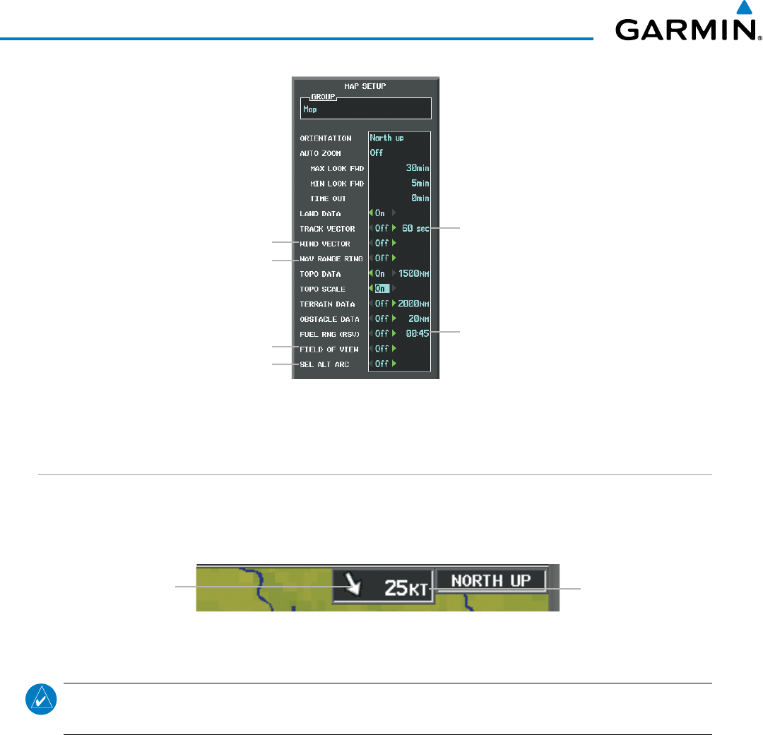
Garmin G1000 Pilot’s Guide for the Beechcraft 200/B200 Series
190-00928-04 Rev. A176
FLIGHT MANAGEMENT
Figure 5-25 Navigation Map Setup Menu - WIND VECTOR On/Off, NAV RANGE RING On/Off, FIELD OF VIEW On/Off,
SEL ALT ARC On/Off, TRACK VECTOR Setup, FUEL RNG (RSV) Setup
Track Vector
- On/Off
- Look Ahead Time
Fuel Range Ring
- On/Off
- Fuel Reserve Time
Wind Vector On/Off
Nav Range Ring On/Off
SVS Field of View On/Off
Selected Altitude Arc On/Off
WIND VECTOR
The map displays a wind vector arrow in the upper right-hand portion of the screen. Wind vector information
is displayed as a white arrow pointing in the direction in which the wind is moving for wind speeds greater than
or equal to 1 kt.
Figure 5-26 Navigation Map - Wind Vector
Wind Direction Wind Speed
NOTE: The wind vector is not displayed until the aircraft is moving. It is not displayed on the Waypoint
Information pages.
Displaying/removing the wind vector:
1) Press the MENU Key with the Navigation Map Page displayed. The cursor flashes on the ‘Map Setup’ option.
2) Press the ENT Key. The Map Setup Menu is displayed.
3) Select the ‘Map’ group.
4) Press the ENT Key.
5) Highlight the ‘WIND VECTOR’ field.
6) Select ‘On’ or ‘Off’.
7) Press the FMS Knob to return to the Navigation Map Page.
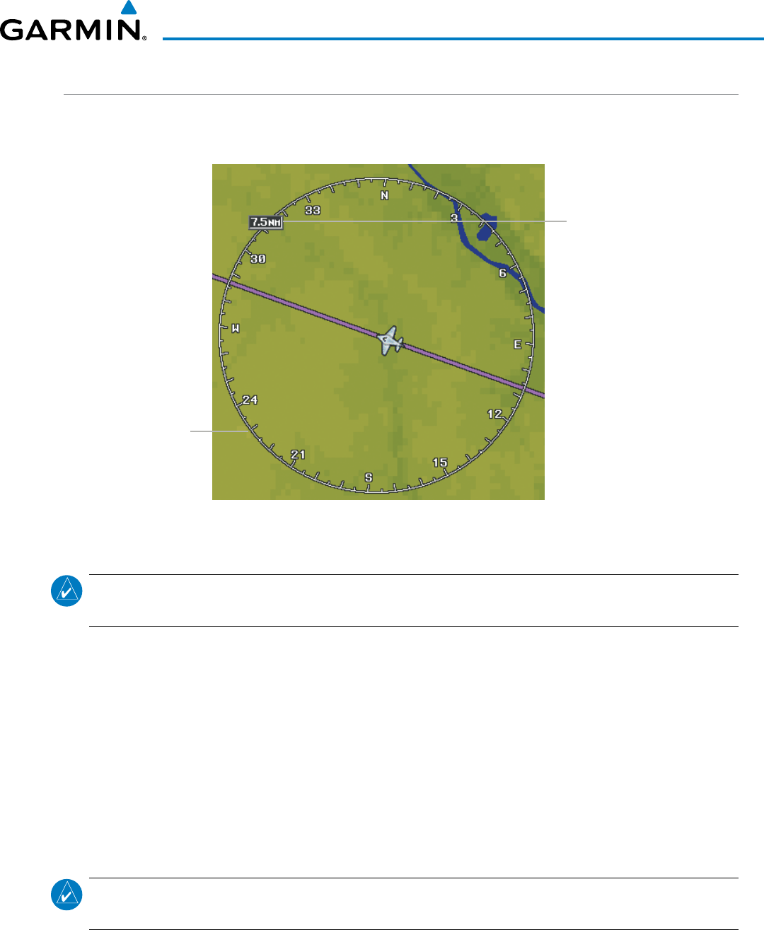
190-00928-04 Rev. A
Garmin G1000 Pilot’s Guide for the Beechcraft 200/B200 Series
177
FLIGHT MANAGEMENT
NAV RANGE RING
The Nav Range Ring shows the direction of travel (ground track) on a rotating compass card. The range is
determined by the map range. The range is 1/4 of the map range (e.g., 7.5 nm on a 30 nm map).
Figure 5-27 Navigation Map - Nav Range Ring
Nav Range Ring
Range (radius)
NOTE: The Nav Range Ring is not displayed on the Waypoint Information pages, Nearest pages, or Direct-to
Window map.
Displaying/removing the Nav Range Ring:
1) Press the MENU Key with the Navigation Map Page displayed. The cursor flashes on the ‘Map Setup’ option.
2) Press the ENT Key. The Map Setup Menu is displayed.
3) Select the ‘Map’ group.
4) Press the ENT Key.
5) Highlight the ‘NAV RANGE RING’ field.
6) Select ‘On’ or ‘Off’.
7) Press the FMS Knob to return to the Navigation Map Page.
NOTE: The Nav Range Ring is referenced to either magnetic or true north, based on the selection on the AUX
- System Setup Page.
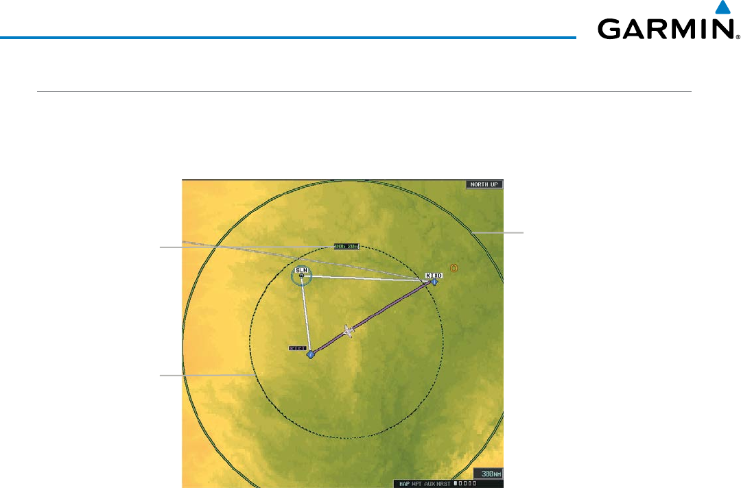
Garmin G1000 Pilot’s Guide for the Beechcraft 200/B200 Series
190-00928-04 Rev. A178
FLIGHT MANAGEMENT
FUEL RANGE RING
The map can display a fuel range ring which shows the remaining flight distance. A dashed green circle
indicates the selected range to reserve fuel. A solid green circle indicates the total endurance range. If only
reserve fuel remains, the range is indicated by a solid yellow circle.
Figure 5-28 Navigation Map - Fuel Range Ring
Range to Reserve Fuel
Time to Reserve Fuel Total Endurance Range
Displaying/removing the fuel range ring and selecting a fuel range time:
1) Press the MENU Key with the Navigation Map Page displayed. The cursor flashes on the ‘Map Setup’ option.
2) Press the ENT Key. The Map Setup Menu is displayed.
3) Select the ‘Map’ group.
4) Press the ENT Key.
5) Highlight the ‘FUEL RNG (RSV)’ field.
6) Select ‘On’ or ‘Off’.
7) Highlight the fuel reserve time field. This time should be set to the amount of flight time equal to the amount
of fuel reserve desired.
8) To change the reserve fuel time, enter a time (00:00 to 23:59; hours:minutes). The default setting is 00:45
minutes.
9) Press the ENT Key.
10) Press the FMS Knob to return to the Navigation Map Page.
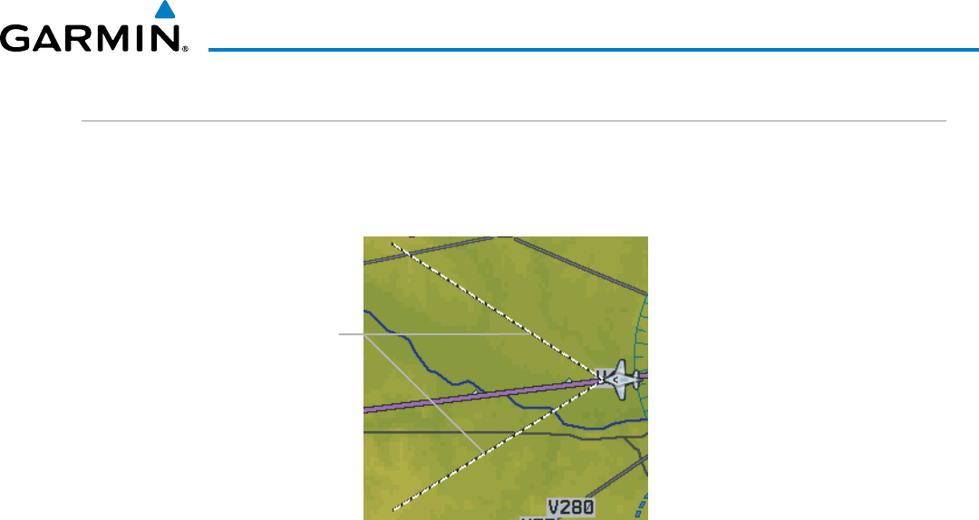
190-00928-04 Rev. A
Garmin G1000 Pilot’s Guide for the Beechcraft 200/B200 Series
179
FLIGHT MANAGEMENT
FIELD OF VIEW (SVS)
The map can display the boundaries of the PFD Synthetic Vision System (SVS) lateral field of view. The field
of view is shown as two dashed lines forming a V shape in front of the aircraft symbol on the map. This is only
available if SVS is installed on the aircraft.
Figure 5-29 Navigation Map - Field of View
Lateral Field
of View
Boundaries
Displaying/removing the field of view:
1) Press the MENU Key with the Navigation Map Page displayed. The cursor flashes on the ‘Map Setup’ option.
2) Press the ENT Key. The Map Setup Menu is displayed.
3) Select the ‘Map’ group.
4) Press the ENT Key.
5) Highlight the ‘FIELD OF VIEW’ field.
6) Select ‘On’ or ‘Off’.
7) Press the FMS Knob to return to the Navigation Map Page.
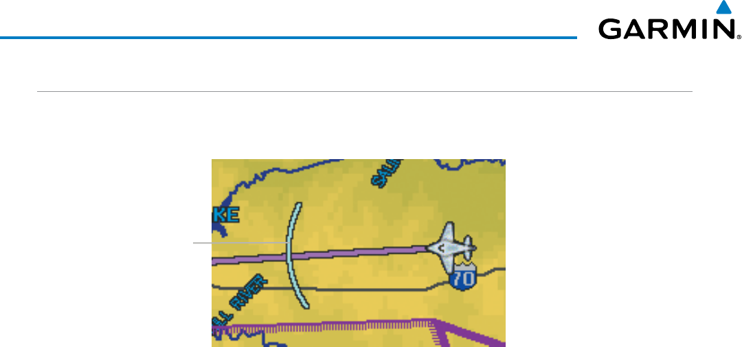
Garmin G1000 Pilot’s Guide for the Beechcraft 200/B200 Series
190-00928-04 Rev. A180
FLIGHT MANAGEMENT
SELECTED ALTITUDE INTERCEPT ARC
The map can display the location along the current track where the aircraft will intercept the selected altitude.
The location will be shown as a light blue arc when the aircraft is actuallly climbing or descending.
Figure 5-30 Navigation Map - Range to Altitude Arc
Range to
Altitude Arc
Displaying/removing the selected altitude intercept arc:
1) Press the MENU Key with the Navigation Map Page displayed. The cursor flashes on the ‘Map Setup’ option.
2) Press the ENT Key. The Map Setup Menu is displayed.
3) Select the ‘Map’ group.
4) Press the ENT Key.
5) Highlight the ‘SEL ALT ARC’ field.
6) Select ‘On’ or ‘Off’.
7) Press the FMS Knob to return to the Navigation Map Page.
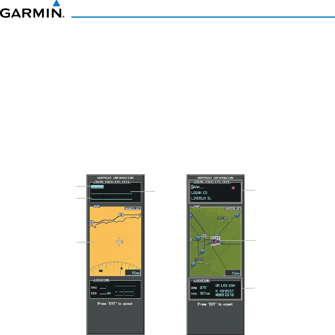
190-00928-04 Rev. A
Garmin G1000 Pilot’s Guide for the Beechcraft 200/B200 Series
181
FLIGHT MANAGEMENT
5.3 WAYPOINTS
Waypoints are predetermined geographical positions (internal database) or pilot-entered positions, and are
used for all phases of flight planning and navigation.
Communication and navigation frequencies can be tuned “automatically” from various Waypoint Information
(WPT) pages, Nearest (NRST) pages, and the Nearest Airports Window (on PFD). This auto-tuning feature
simplifies frequency entry over manual tuning. Refer to the Audio Panel and CNS section for details on auto-
tuning.
Waypoints can be selected by entering the ICAO identifier, entering the name of the facility, or by entering
the city name. See the System Overview section for detailed instructions on entering data in the G1000. As a
waypoint identifier, facility name, or location is entered, the G1000’s Spell’N’Find™ feature scrolls through the
database, displaying those waypoints matching the characters which have been entered to that point. A direct-to
navigation leg to the selected waypoint can be initiated by pressing the Direct-to Key on any of the waypoint
pages.
Figure 5-31 Waypoint Information Window
Map Area Showing
Entered Waypoint
Identifier Entry Field
Entered Waypoint on
Map
Facility
Entry Field
City Entry Field
- Waypoint Identifier
- Type (symbol)
- Facility Name
- City
Waypoint Location
If duplicate entries exist for the entered facility name or location, additional entries may be viewed by continuing
to turn the small FMS Knob during the selection process. If duplicate entries exist for an identifier, a Duplicate
Waypoints Window is displayed when the ENT Key is pressed.
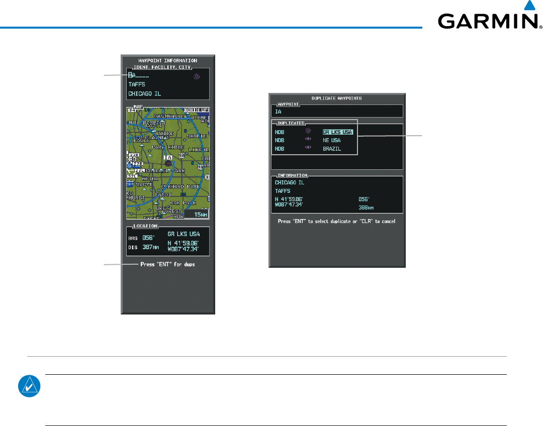
Garmin G1000 Pilot’s Guide for the Beechcraft 200/B200 Series
190-00928-04 Rev. A182
FLIGHT MANAGEMENT
Figure 5-32 Waypoint Information Window - Duplicate Identifier
Duplicate Message
Identifier with
Duplicates
Duplicate
Waypoints
AIRPORTS
NOTE: ‘North Up’ orientation on the Airport Information Page cannot be changed; the pilot needs to be
aware of proper orientation if the Navigation Map orientation is different from the Airport Information Page
Map.
The Airport Information Page is the first page in WPT group and allows the pilot to view airport information,
load frequencies (COM, NAV, and lighting), review runways, and review instrument procedures that may be
involved in the flight plan. See the Audio Panel and CNS Section for more information on loading frequencies
(auto-tuning). After engine startup, the Airport Information Page defaults to the airport where the aircraft is
located. After a flight plan has been loaded, it defaults to the destination airport. On a flight plan with multiple
airports, it defaults to the airport which is the current active waypoint.
In addition to displaying a map of the currently selected airport and surrounding area, the Airport Information
Page displays airport information in three boxes labeled ‘AIRPORT’, ‘RUNWAYS’, and ‘FREQUENCIES’. For
airports with multiple runways, information for each runway is available. This information is viewed on the
Airport Information Page by pressing the INFO softkey until INFO-1 is displayed.
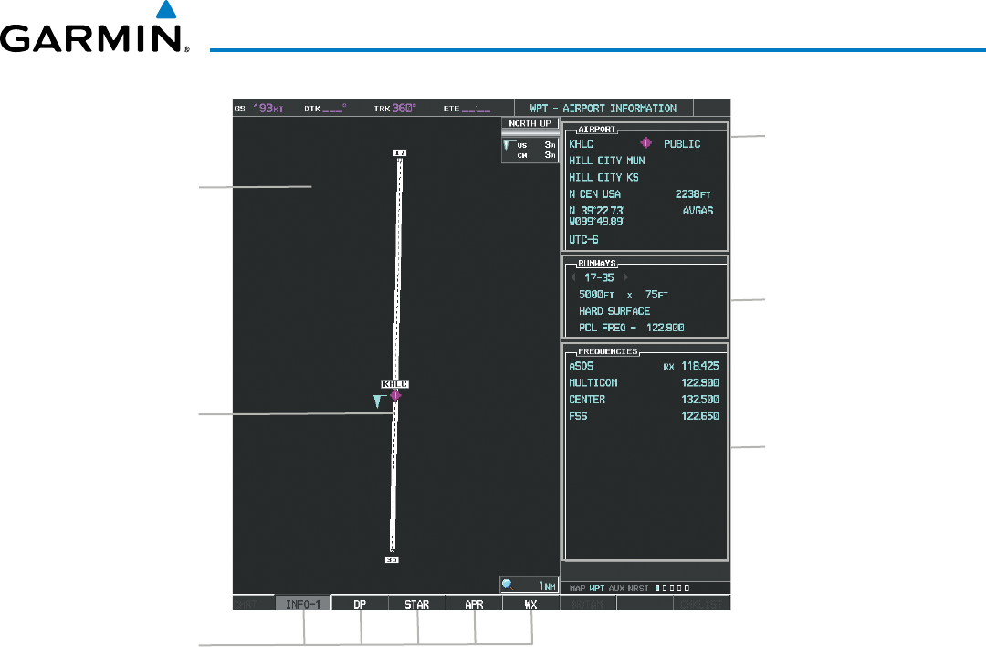
190-00928-04 Rev. A
Garmin G1000 Pilot’s Guide for the Beechcraft 200/B200 Series
183
FLIGHT MANAGEMENT
Figure 5-33 Airport Information Page
Airport/Runway
Diagram
Navigation Map
Showing Selected
Airport
Runway Information
- Designation
- Length/Width/Surface
- Lighting Available
Airport Information
- ID/Facility/City
- Usage Type/Region
- Lat/Long/Elev
- Fuel Available
- Time Zone (UTC Offset)
COM/NAV Freq. Info.
- Identification
- Frequency
- Availability
- Additional Information
Softkeys
The following descriptions and abbreviations are used on the Airport Information Page:
• Usage type: Public, Military, Private, or Heliport
• Runway surface type: Hard, Turf, Sealed, Gravel, Dirt, Soft, Unknown, or Water
• Runway lighting type: No Lights, Part Time, Full Time, Unknown, or PCL Freq (for pilot-controlled
lighting)
• COM Availability: TX (transmit only), RX (receive only), PT (part time), i (additional information available)
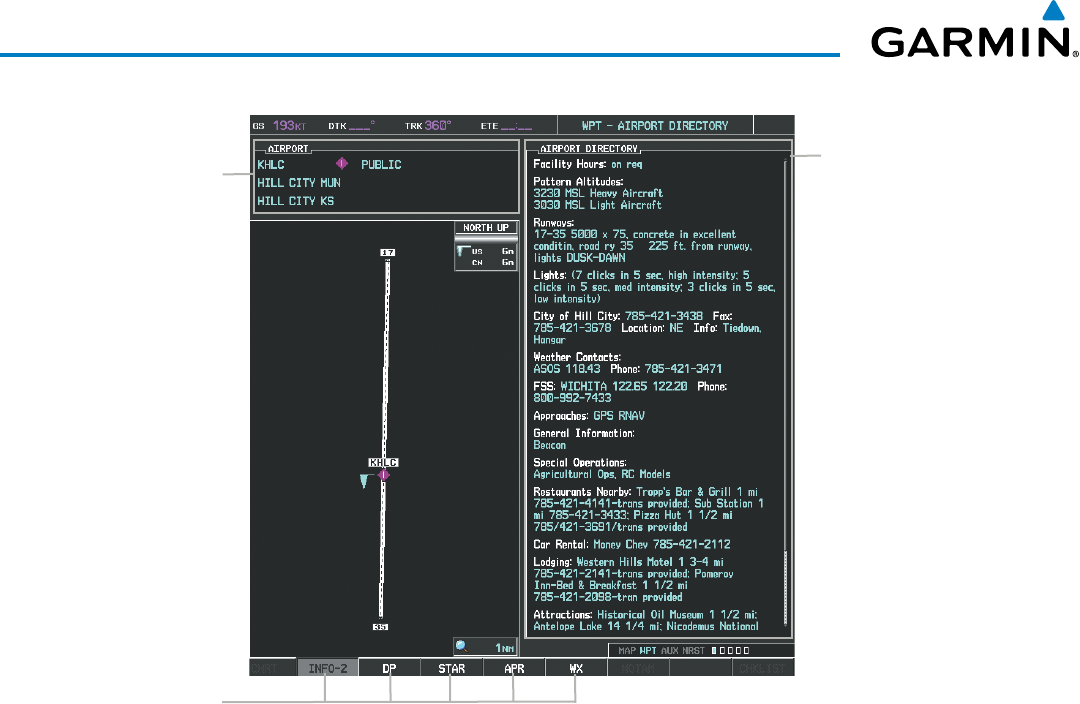
Garmin G1000 Pilot’s Guide for the Beechcraft 200/B200 Series
190-00928-04 Rev. A184
FLIGHT MANAGEMENT
Figure 5-34 Airport Directory Page Example
Airport Information
- ID/Facility/City
- Usage Type/Region
Airport Directory
Information
Softkeys
The AOPA directory information is viewed on the Airport Directory Page by pressing the INFO softkey until
INFO-2 is displayed. The following are types of AOPA airport directory informantion shown (if available) on
the Airport Directory Page:
• Airport: Identifier, Site
Number, Name, City, State
• Traffic Pattern Altitudes
(TPA): Aircraft Class/Altitude
• Runway: Headings, Length,
Width, Obstructions, Surface
• Phones: Phone/Fax Numbers • Weather: Service Type,
Frequency, Phone Number
• Obstructions: General Airport
Obstructions
• Hours: Facility Hours, Light
Hours, Tower Hours, Beacon
Hours
• Flight Service Station (FSS):
FSS Name, Phone Numbers
• Special Operations at
Airport
• Location: Sectional, Magnetic
Variation
• Instrument Approaches:
Published Approach, Freq.
• Services Available: Category,
Specific Service
• Frequencies: Type/Frequency • NAVAIDS: Type, Identifier,
Frequency, Radial, Distance
• Notes: Airport Notes
• Transportation: Ground
Transportation Type Available
• Noise: Noise Abatement
Procedures
• Pilot Controlled Lighting:
High/Med/Low Clicks/Second
• Approach: Approach Facility
Name, Frequency, Frequency
Parameter
• Charts: Low Altitude Chart
Number
• FBO: Type, Frequencies,
Services, Fees, Fuel, Credit
Cards, Phone/Fax Numbers

190-00928-04 Rev. A
Garmin G1000 Pilot’s Guide for the Beechcraft 200/B200 Series
185
FLIGHT MANAGEMENT
Selecting an airport for review by identifier, facility name, or location:
1) From the Airport Information Page, press the FMS Knob.
2) Use the FMS Knobs and enter an identifier, facility name, or location.
3) Press the ENT Key.
4) Press the FMS Knob to remove the cursor.
Selecting a runway:
1) With the Airport Information Page displayed, press the FMS Knob to activate the cursor.
2) Turn the large FMS Knob to place the cursor in the ‘RUNWAYS’ Box, on the runway designator.
3) Turn the small FMS Knob to display the desired runway (if more than one) for the selected airport.
4) To remove the flashing cursor, press the FMS Knob.
Viewing a destination airport:
From the Airport Information Page press the MENU Key. Select ‘View Destination Airport’. The Destination
Airport is displayed.
The Airport Frequencies Box uses the descriptions and abbreviations listed in the following table:
Communication Frequencies Navigation Frequencies
Approach *
Arrival *
ASOS
ATIS
AWOS
Center
Class B *
Class C *
Clearance
Control
CTA *
Departure *
Gate
Ground
Helicopter
Multicom
Other
Pre-Taxi
Radar
Ramp
Terminal *
TMA *
Tower
TRSA *
Unicom
ILS
LOC
* May include Additional Information
Table 5-5 Airport Frequency Abbreviations
A departure, arrival, or approach can be loaded using the softkeys on the Airport Information Page. See the
Procedures section for details. METARs or TAFs applicable to the selected airport can be selected for display (see
the Hazard Avoidance section for details about weather).
The G1000 provides a NRST Softkey on the PFD, which gives the pilot quick access to nearest airport
information (very useful if an immediate landing is required). The Nearest Airports Window displays a list of
up to 25 of the nearest airports (three entries can be displayed at one time). If there are more than three they are
displayed in a scrollable list. If there are no nearest airports available, “NONE WITHIN 200NM” is displayed.
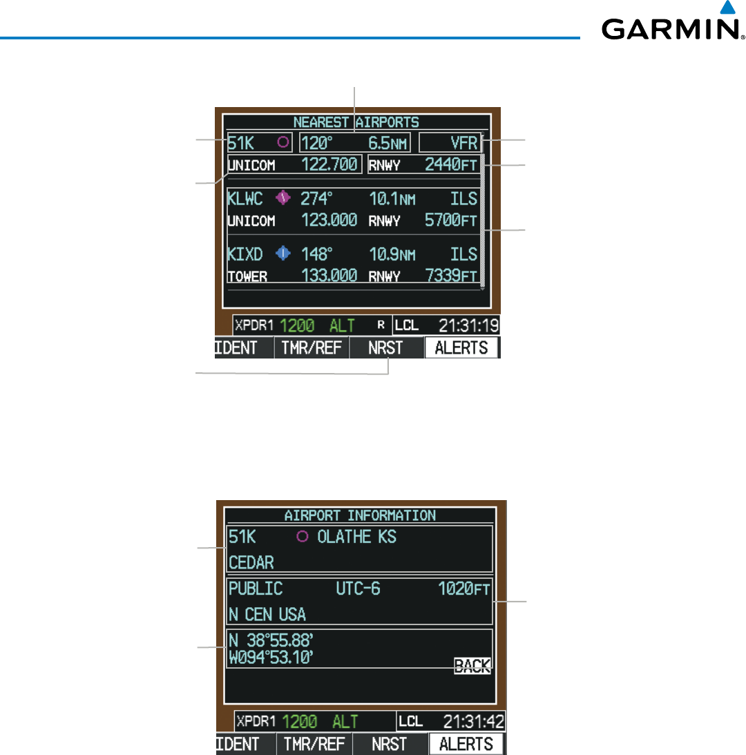
Garmin G1000 Pilot’s Guide for the Beechcraft 200/B200 Series
190-00928-04 Rev. A186
FLIGHT MANAGEMENT
Figure 5-35 Nearest Airports Window on PFD
COM Freq. Info.
- Identification
- Frequency
Airport Identifier/
Type Length of Longest
Runway
Approach Available
Additional Airports
(within 200 nm)
NRST Softkey
Bearing/Distance to Airport
Pressing the ENT Key displays the PFD Airport Information Window for the highlighted airport. Pressing the
ENT Key again returns to the Nearest Airports Window with the cursor on the next airport in the list. Continued
presses of the ENT Key sequences through the information pages for all airports in the Nearest Airports list.
Figure 5-36 Airport Information Window on PFD
Airport Information
- Usage/Time/Elev
- Region
Airport Information
- Lat/Long
Airport Information
- ID/Type/City
- Facility
The Nearest Airports Page on the MFD is first in the group of NRST pages because of its potential use in
the event of an in-flight emergency. In addition to displaying a map of the currently selected airport and
surrounding area, the page displays nearest airport information in five boxes labeled ‘NEAREST AIRPORTS’,
‘INFORMATION’, ‘RUNWAYS’, ‘FREQUENCIES’, and ‘APPROACHES’.
The selected airport is indicated by a white arrow, and a dashed white line is drawn on the navigation map
from the aircraft position to the nearest airport. Up to four nearest airports, one runway, up to six frequencies,
and up to six approaches are visible at one time. If there are more than can be shown, each list can be scrolled.
If there are no items for display in a boxed area, text indicating that fact is displayed. The currently selected
airport remains in the list until it is unselected.
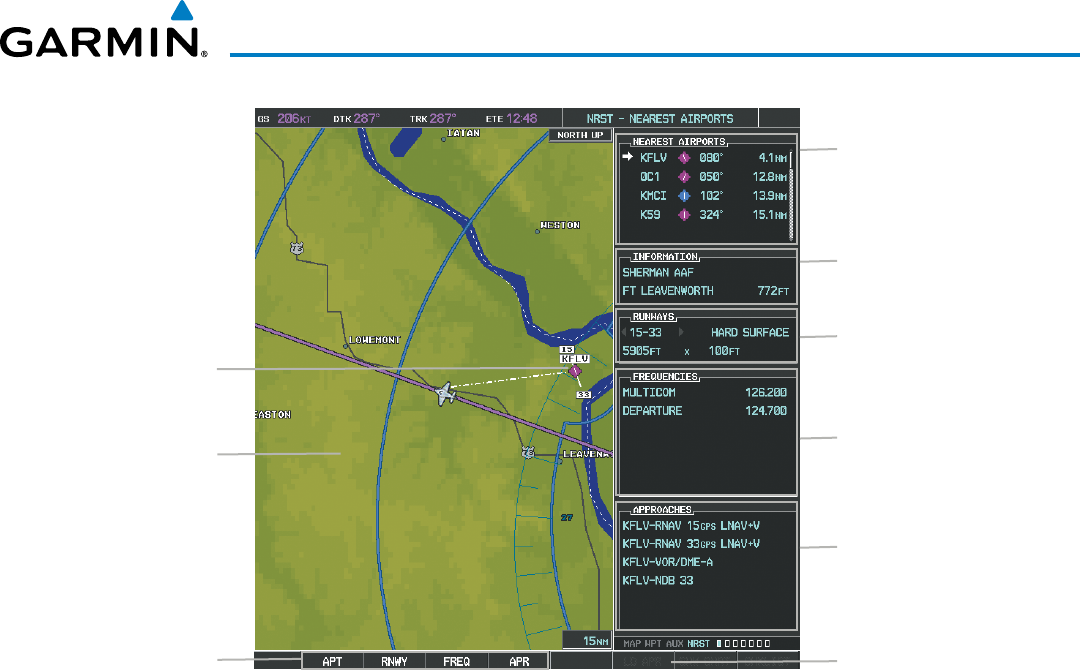
190-00928-04 Rev. A
Garmin G1000 Pilot’s Guide for the Beechcraft 200/B200 Series
187
FLIGHT MANAGEMENT
Figure 5-37 Nearest Airport Page
Nearest Airport
Navigation Map
Showing Nearest
Airport
Runway Information
- Designation/Surface
- Length/Width
Nearest Airports
- ID/Type
- Bearing/Distance
COM/NAV Freq. Info.
- Identification
- Frequency
Window Selection
Softkeys
Airport Information
- Facility/City/Elevation
Approaches Available
LD APR Softkey (only
available if an approach is
highlighted)
Viewing information for a nearest airport on the PFD:
1) Select the NRST Softkey to display the Nearest Airports Window. Press the FMS Knob to activate the cursor.
2) Highlight the airport identifier with the FMS Knob and press the ENT Key to display the Airport Information
Window.
3) To return to the Nearest Airports Window press the ENT Key (with the cursor on ‘BACK’) or press the CLR
Key. The cursor is now on the next airport in the nearest airports list. (Repeatedly pressing the ENT Key
moves through the airport list, alternating between the Nearest Airports Window and the Airport Information
Window.)
4) Press the CLR Key or the NRST Softkey to close the PFD Nearest Airports Window.
Viewing information for a nearest airport on the MFD:
1) Turn the large FMS Knob to select the NRST page group.
2) Turn the small FMS Knob to select the Nearest Airports Page (it is the first page of the group, so it may already
be selected). If there are no Nearest Airports available, “NONE WITHIN 200 NM” is displayed.
3) Select the APT Softkey; or press the FMS Knob; or press the MENU Key, highlight ‘Select Airport Window’ and
press the ENT Key. The cursor is placed in the ‘NEAREST AIRPORTS’ Box. The first airport in the nearest airports
list is highlighted.
4) Turn the FMS Knob to highlight the desired airport. (Pressing the ENT Key also moves to the next airport.)
5) Press the FMS Knob to remove the flashing cursor.

Garmin G1000 Pilot’s Guide for the Beechcraft 200/B200 Series
190-00928-04 Rev. A188
FLIGHT MANAGEMENT
Viewing runway information for a specific airport:
1) With the Nearest Airports Page displayed, select the RNWY Softkey; or press the MENU Key, highlight ‘Select
Runway Window’; and press the ENT Key. The cursor is placed in the ‘RUNWAYS’ Box.
2) Turn the small FMS Knob to select the desired runway.
3) Press the FMS Knob to remove the flashing cursor.
See the Audio Panel and CNS Section for frequency selection and the Procedures section for approaches.
The Nearest Airports Box on the System Setup Page defines the minimum runway length and surface type
used when determining the 25 nearest airports to display on the MFD Nearest Airports Page. A minimum
runway length and/or surface type can be entered to prevent airports with small runways or runways that are
not appropriately surfaced from being displayed. Default settings are 0 feet (or meters) for runway length and
“HARD/SOFT” for runway surface type.
Selecting nearest airport surface matching criteria:
1) Use the FMS Knob to select the System Setup Page.
2) Press the FMS Knob momentarily to activate the flashing cursor.
3) Turn the large FMS Knob to highlight the runway surface field in the Nearest Airports Box.
4) Turn the small FMS Knob to select the desired runway option (ANY, HARD ONLY, HARD/SOFT).
5) Press the ENT Key.
6) Press the FMS Knob to remove the flashing cursor.
Selecting nearest airport minimum runway length matching criteria:
1) Use the FMS Knob to select the System Setup Page.
2) Press the FMS Knob momentarily to activate the flashing cursor.
3) Turn the large FMS Knob to highlight the minimum length field in the Nearest Airport Box.
4) Use the FMS Knob to enter the minimum runway length (zero to 25,000 feet) and press the ENT Key.
5) Press the FMS Knob to remove the flashing cursor.
Figure 5-38 System Setup Page - Nearest Airport Selection Criteria
Nearest Airport Criteria
- Type of Runway Surface
- Minimum Runway Length
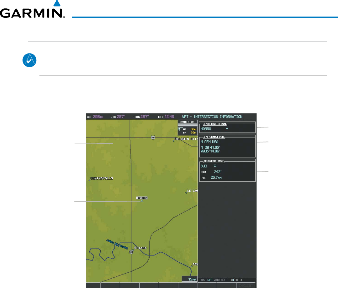
190-00928-04 Rev. A
Garmin G1000 Pilot’s Guide for the Beechcraft 200/B200 Series
189
FLIGHT MANAGEMENT
INTERSECTIONS
NOTE: The VOR displayed on the Intersection Information Page is the nearest VOR, not necessarily the VOR
used to define the intersection.
The Intersection Information Page is used to view information about intersections. In addition to displaying
a map of the currently selected intersection and surrounding area, the Intersection Information Page displays
intersection information in three boxes labeled ‘INTERSECTION’, ‘INFORMATION’, and ‘NEAREST VOR’.
Figure 5-39 Intersection Information Page
Selected Intersection
Navigation Map
Showing Selected
Intersection
Intersection Identifier
Nearest VOR Info
- Identifier/Type (symbol)
- Radial to VOR
- Distance to VOR
Intersection Info
- Region
- Lat/Long
Selecting an intersection:
1) With the Intersection Information Page displayed, enter an identifier in the Intersection Box.
2) Press the ENT Key.
3) Press the FMS
Knob to remove the flashing cursor.
Or:
1) With the Nearest Intersections Page displayed, press the FMS Knob.
2) Press the ENT Key or turn either FMS Knob to select an identifier in the Nearest Intersection Box.
3) Press the FMS Knob to remove the flashing cursor.
The Nearest Intersections Page can be used to quickly find an intersection close to the flight path. In addition
to displaying a map of the surrounding area, the page displays information for up to 25 nearest intersections in
three boxes labeled ‘NEAREST INT’, ‘INFORMATION’, and ‘REFERENCE VOR’.
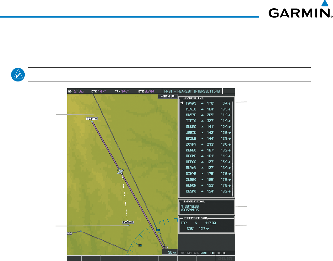
Garmin G1000 Pilot’s Guide for the Beechcraft 200/B200 Series
190-00928-04 Rev. A190
FLIGHT MANAGEMENT
The selected intersection is indicated by a white arrow. Up to sixteen intersections are visible at a time. If
there are more than can be shown, the list can be scrolled. If there are no items for display, text indicating that
fact is displayed.
NOTE: The list only includes waypoints that are within 200 nm.
Figure 5-40 Nearest Intersections Page
Nearest
Intersection
Navigation Map
Showing Nearest
Intersection
Intersection Information
- Identifier/Symbol
- Bearing/Distance to
intersection from
aircraft position
Reference VOR Info
- Identifier/Type (symbol)
- VOR Frequency
- Bearing/Distance to VOR
Intersection Lat/Long
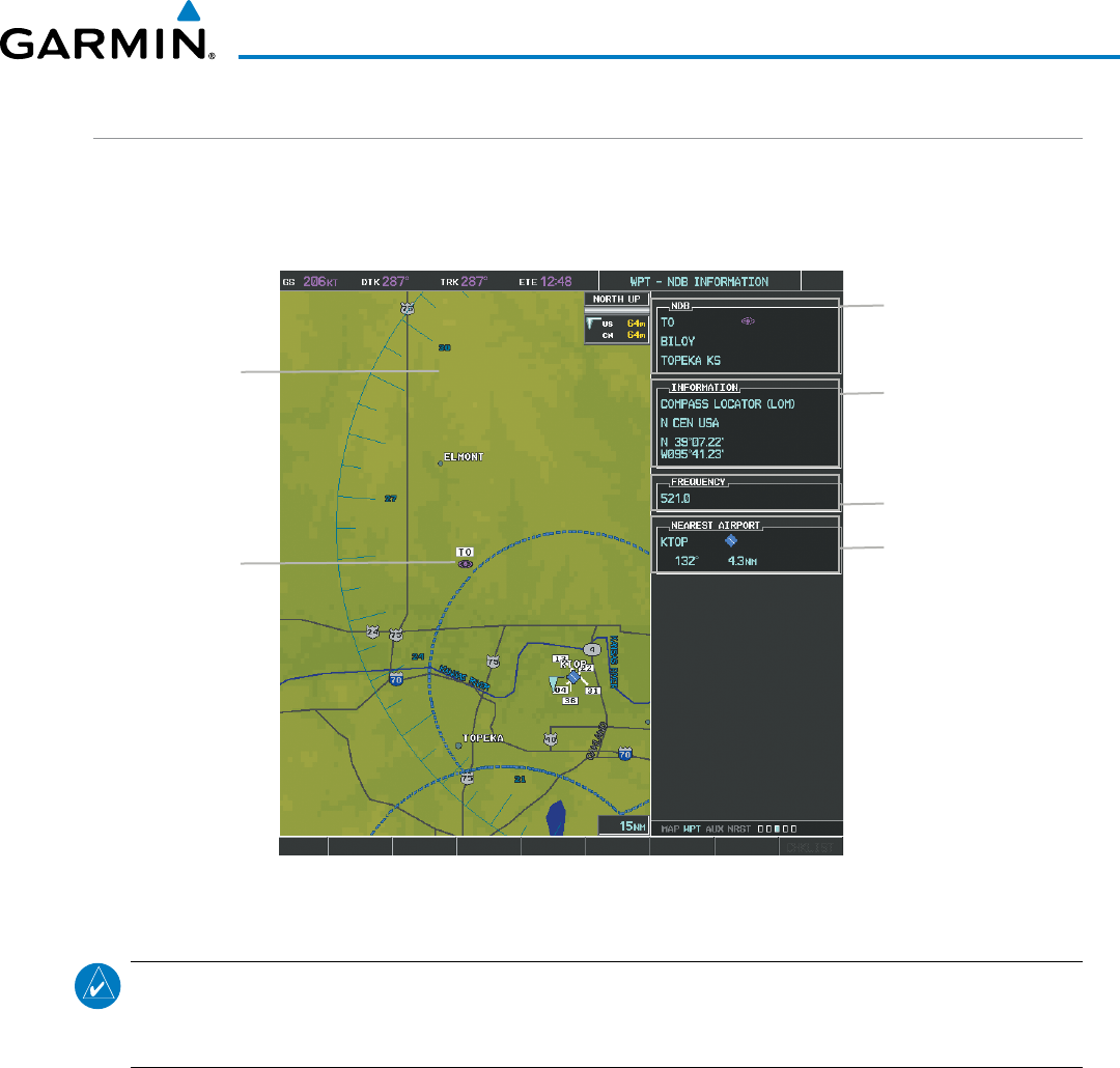
190-00928-04 Rev. A
Garmin G1000 Pilot’s Guide for the Beechcraft 200/B200 Series
191
FLIGHT MANAGEMENT
NDBS
The NDB Information Page is used to view information about NDBs. In addition to displaying a map of
the currently selected NDB and surrounding area, the page displays NDB information in four boxes labeled
‘NDB’, ‘INFORMATION’, ‘FREQUENCY’, and ‘NEAREST AIRPORT’.
Figure 5-41 NDB Information Page
Selected NDB
Navigation Map
Showing Selected
NDB
NDB Identifier/Type
- Facility Name
- Nearest City
Nearest Airport Info
- Identifier/Type (symbol)
- Bearing/Distance to
Airport
NDB Information
- Type
- Region
- Lat/Long
NDB Frequency
NOTE: Compass locator (LOM, LMM): a low power, low or medium frequency radio beacon installed in
conjunction with the instrument landing system. When LOM is used, the locator is at the Outer Marker;
when LMM is used, the locator is at the Middle Marker.
Selecting an NDB:
1) With the NDB Information Page displayed, enter an identifier, the name of the NDB, or the city in which it’s
located in the NDB Box.
2) Press the ENT Key.
3) Press the
FMS
Knob to remove the flashing cursor.
Or:
1) With the Nearest NDB Page displayed, press the FMS Knob.
2) Press the ENT Key or turn either FMS Knob to select an identifier in the Nearest NDB Box.
3) Press the FMS Knob to remove the flashing cursor.
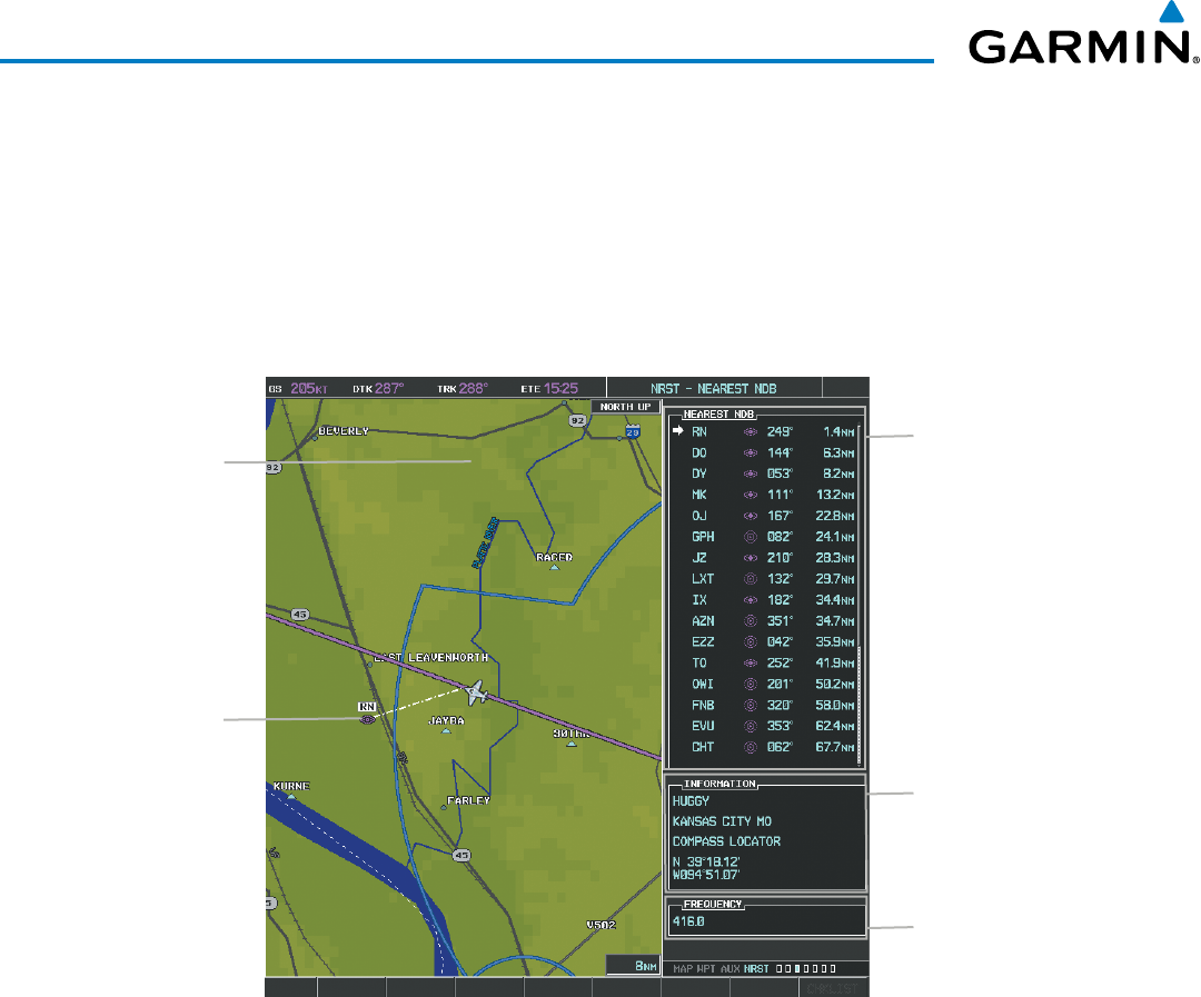
Garmin G1000 Pilot’s Guide for the Beechcraft 200/B200 Series
190-00928-04 Rev. A192
FLIGHT MANAGEMENT
The Nearest NDB Page can be used to quickly find a NDB close to the flight path. In addition to displaying
a map of the surrounding area, the page displays information for up to 25 nearest NDBs in three boxes labeled
‘NEAREST NDB’, ‘INFORMATION’, and ‘FREQUENCY’.
A white arrow before the NDB identifier indicates the selected NDB. Up to sixteen NDBs are visible at a time.
If there are more than can be shown, each list can be scrolled. The list only includes waypoints that are within
200nm. If there are no NDBs in the list, text indicating that there are no nearest NDBs is displayed. If there are
no nearest NDBs in the list, the information and frequency fields are dashed.
Figure 5-42 Nearest NDB Page
Nearest NDB
Navigation Map
Showing Selected
NDB
NDB Information
- Facility Name/City
- Type
- Lat/Long
NDB Identifier/Symbol
- Bearing/Distance to
NDB from aircraft
position
NDB Frequency
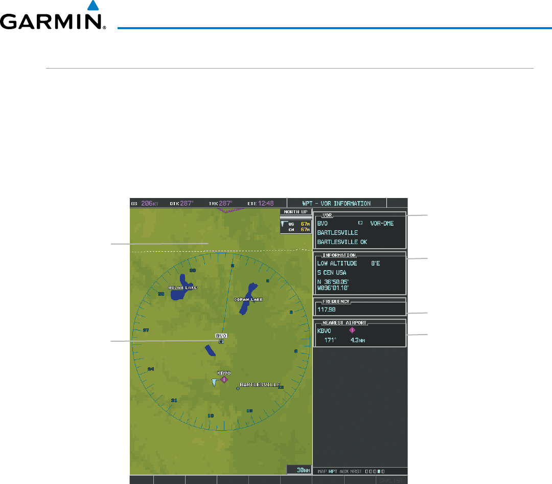
190-00928-04 Rev. A
Garmin G1000 Pilot’s Guide for the Beechcraft 200/B200 Series
193
FLIGHT MANAGEMENT
VORS
The VOR Information Page can be used to view information about VOR and ILS navigation signals, or to
quickly auto-tune a VOR or ILS frequency. Localizer information cannot be viewed on the VOR Information
Page. If a VOR station is combined with a TACAN station it is listed as a VORTAC on the VOR Information
Page and if it includes only DME, it is displayed as VOR-DME.
In addition to displaying a map of the currently selected VOR and surrounding area, the VOR Information
Page displays VOR information in four boxes labeled ‘VOR’, ‘INFORMATION’, ‘FREQUENCY’, and ‘NEAREST
AIRPORT’.
Figure 5-43 VOR Information Page
Selected VOR
Navigation Map
Showing
Selected VOR
VOR Identifier/Type
- Facility Name
- Nearest City
Nearest Airport Info
- Identifier/Type (symbol)
- Bearing/Distance to
Airport
VOR Information
- Class/Magnetic Variation
- Region
- Lat/Long
VOR Frequency
The VOR classes used in the VOR information box are: LOW ALTITUDE, HIGH ALTITUDE, and
TERMINAL.
Selecting a VOR:
1) With the VOR Information Page displayed, enter an identifier, the name of the VOR, or the city in which it’s
located in the VOR Box.
2) Press the ENT Key.
3) Press the FMS Knob to remove the flashing cursor.
Or:
1) With the Nearest VOR Page displayed, press the FMS Knob or press the VOR Softkey.
2) Press the ENT Key or turn either FMS Knob to select an identifier in the Nearest VOR Box.
3) Press the FMS Knob to remove the flashing cursor.
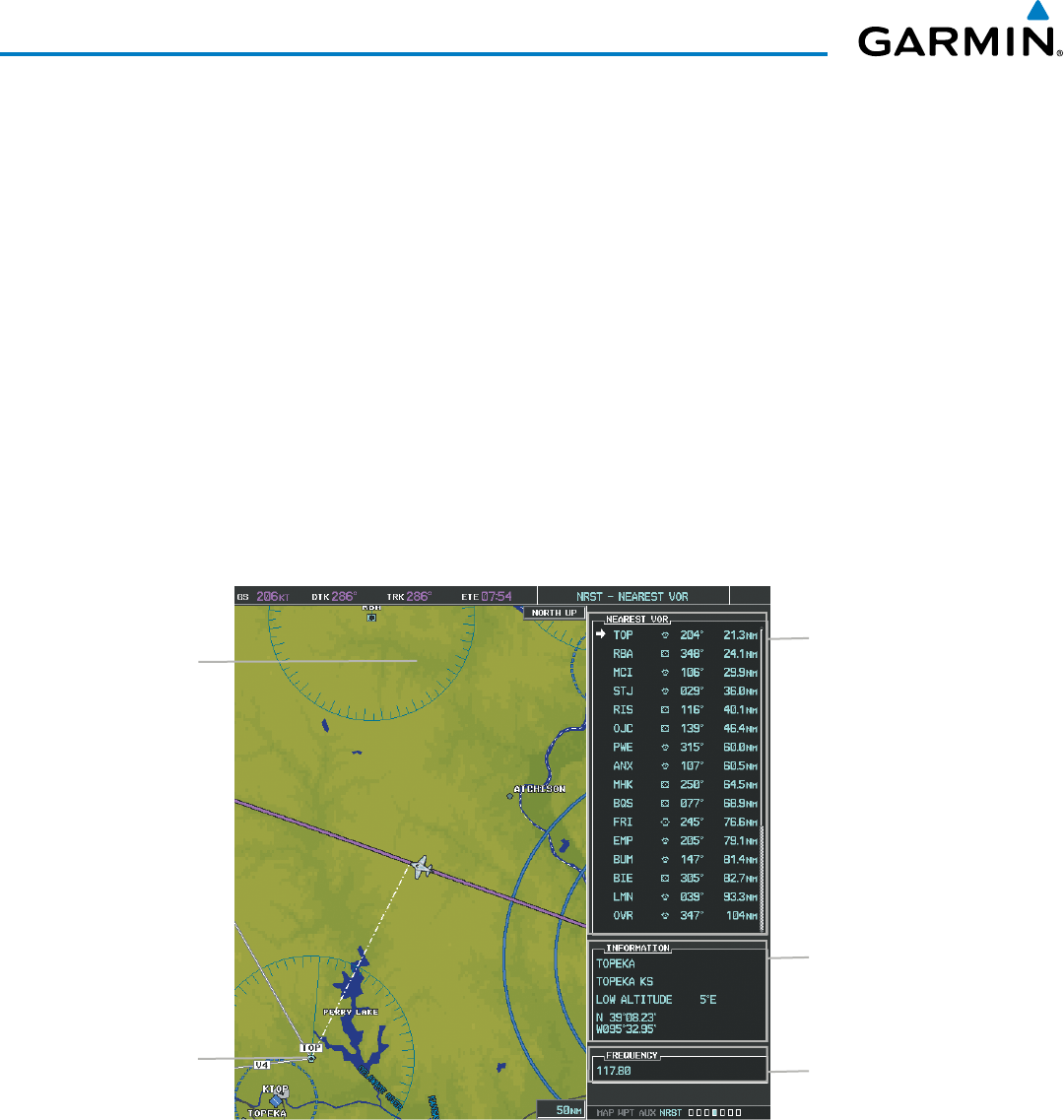
Garmin G1000 Pilot’s Guide for the Beechcraft 200/B200 Series
190-00928-04 Rev. A194
FLIGHT MANAGEMENT
Or:
1) With the Nearest VOR Page displayed, press the MENU Key.
2) Highlight ‘Select VOR Window’, and press the ENT Key.
3) Press the ENT Key or turn either FMS Knob to select an identifier in the Nearest VOR Box.
4) Press the FMS Knob to remove the flashing cursor.
The Nearest VOR Page can be used to quickly find a VOR station close to the aircraft. Also, a NAV frequency
from a selected VOR station can be loaded from the Nearest VOR Page. In addition to displaying a map of
the surrounding area, the Nearest VOR Page displays information for up to 25 nearest VOR stations in three
boxes labeled ‘NEAREST VOR’, ‘INFORMATION’, and ‘FREQUENCY’. The list only includes waypoints that
are within 200 nm
.
A white arrow before the VOR identifier indicates the selected VOR. Up to sixteen VORs are visible at a
time. If there are more than can be shown, each list can be scrolled. If there are no VORs in the list, text
indicating that there are no nearest VORs is displayed. If there are no nearest VORs in the list, the information
is dashed.
Figure 5-44 Nearest VOR Page
Nearest VOR
Navigation Map
Showing Nearest
VOR
VOR Information
- Facility Name/City
- Class/Magnetic Variation
- Lat/Long
VOR Identifier/Symbol
- Bearing/Distance to VOR
from aircraft position
VOR Frequency
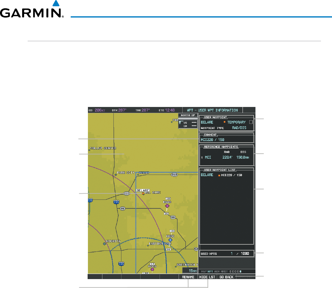
190-00928-04 Rev. A
Garmin G1000 Pilot’s Guide for the Beechcraft 200/B200 Series
195
FLIGHT MANAGEMENT
USER WAYPOINTS
The system can create and store up to 1,000 user-defined waypoints. User waypoints can be created from any
map page (except PFD Inset Map, AUX-Trip Planning Page, or Procedure Pages) by selecting a position on the
map using the Joystick, or from the User Waypoint Information Page by referencing a bearing/distance from
an existing waypoint, bearings from two existing waypoints, or a latitude and longitude. Once a waypoint has
been created, it can be renamed, deleted, or moved. Temporary user waypoints are erased upon system power
down.
Figure 5-45 User Waypoint Information Page
Selected User
Waypoint
Navigation Map
Showing Selected
User Waypoint
User Waypoint Info
- Identifier
- Temporary/Normal
- Waypoint Type
User Waypoint List
- Identifier
- Comment
Reference Wpt/Info
- Identifier/Rad/Dist or
- Identifiers/Radials or
- Region/Lat/Long
Softkeys
User Wpt Comment
# User Wpts Used
Displayed if User Wpt
was created on map
page
Selecting a User Waypoint:
1) With the User Waypoint Information Page displayed, enter the name of the User Waypoint, or scroll to the
desired waypoint in the User Waypoint List using the large FMS Knob.
2) Press the ENT Key.
3) Press the
FMS
Knob to remove the flashing cursor.
Or:
1) With the Nearest User Waypoints Page displayed, press the FMS Knob.
2) Press the ENT Key or turn either FMS Knob to select an identifier in the Nearest USR Box.
3) Press the FMS Knob to remove the flashing cursor.
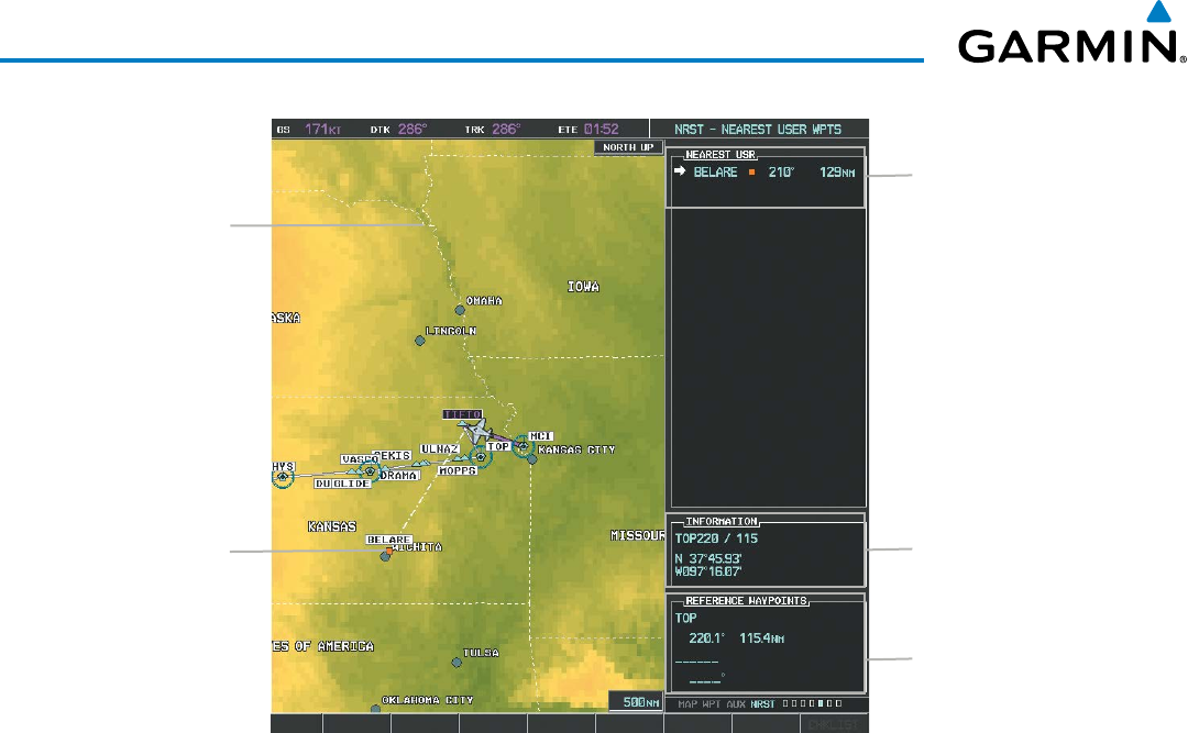
Garmin G1000 Pilot’s Guide for the Beechcraft 200/B200 Series
190-00928-04 Rev. A196
FLIGHT MANAGEMENT
Figure 5-46 Nearest User Waypoint Page
Selected User
Waypoint
Navigation Map
Showing Selected
User Waypoint
Nearest User Wpt List
- Identifier
- Bearing/Distance from
aircraft position
User Waypoint Info
- Comment
- Lat/Long
Reference Wpt Info
- Identifier
- Radial/Distance
CREATING USER WAYPOINTS
User waypoints can be created from the User Waypoint Information Page in the following ways:
Creating user waypoints from the User Waypoint Information Page:
1) Select the NEW Softkey, or press the MENU Key and select ‘Create New User Waypoint’.
2) Enter a user waypoint name (up to six characters).
3) Press the ENT Key. The current aircraft position is the default location of the new waypoint.
4) If desired, define the type and location of the waypoint in one of the following ways:
a) Select “RAD/RAD” using the small FMS Knob, press the ENT Key, and enter the two reference waypoint
identifiers and radials into the REFERENCE WAYPOINTS window using the FMS Knobs.
Or:
b) Select “RAD/DIS” using the small FMS Knob, press the ENT Key, and enter the reference waypoint identifier,
the radial, and the distance into the REFERENCE WAYPOINTS window using the FMS Knobs.
Or:
c) Select “LAT/LON” using the small FMS Knob, press the ENT Key, and enter the latitude and longitude into
the INFORMATION window using the FMS Knobs.
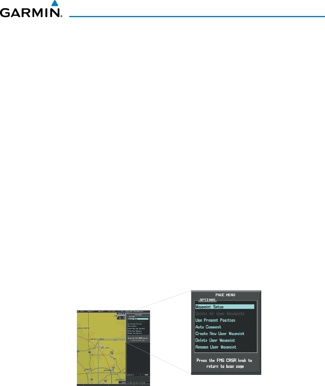
190-00928-04 Rev. A
Garmin G1000 Pilot’s Guide for the Beechcraft 200/B200 Series
197
FLIGHT MANAGEMENT
5) Press the ENT Key to accept the new waypoint.
6) If desired, change the storage method of the waypoint to “TEMPORARY” or “NORMAL” by moving the cursor
to “TEMPORARY” and selecting the ENT Key to check or uncheck the box.
7) Press the FMS Knob to remove the flashing cursor.
Or:
1) Press the FMS Knob to activate the cursor.
2) Enter a user waypoint name (up to six characters).
3) Press the ENT Key. The message ‘Are you sure you want to create the new User Waypoint AAAAAA?’ is
displayed.
4) With ‘YES’ highlighted, press the ENT Key.
5) If desired, define the type and location of the waypoint in one of the following ways:
a) Select “RAD/RAD” using the small FMS Knob, press the ENT Key, and enter the two reference waypoint
identifiers and radials into the REFERENCE WAYPOINTS window using the FMS Knobs.
Or:
b) Select “RAD/DIS” using the small FMS Knob, press the ENT Key, and enter the reference waypoint identifier,
the radial, and the distance into the REFERENCE WAYPOINTS window using the FMS Knobs.
Or:
c) Select “LAT/LON” using the small FMS Knob, press the ENT Key, and enter the latitude and longitude into
the INFORMATION window using the FMS Knobs.
6) Press the ENT Key to accept the new waypoint.
7) If desired, change the storage method of the waypoint to “TEMPORARY” or “NORMAL” by moving the cursor
to “TEMPORARY” and selecting the ENT Key to check or uncheck the box.
8) Press the FMS Knob to remove the flashing cursor.
Figure 5-47 User Waypoint Information Page Menu

Garmin G1000 Pilot’s Guide for the Beechcraft 200/B200 Series
190-00928-04 Rev. A198
FLIGHT MANAGEMENT
Creating user waypoints from map pages:
1) Press the Joystick to activate the panning function and pan to the map location of the desired user waypoint.
2) Press the ENT Key. The User Waypoint Information Page is displayed with the captured position.
NOTE: If the pointer has highlighted a map database feature, one of three things happens upon pressing
the
ENT
Key: 1) information about the selected feature is displayed instead of initiating a new waypoint,
2) a menu pops up allowing a choice between ‘Review Airspaces’ or ‘Create User Waypoint’, or 3) a new
waypoint is initiated with the default name being the selected map item.
3) Enter a user waypoint name (up to six characters).
4) Press the ENT Key to accept the selected name. The first reference waypoint box is highlighted.
5) If desired, define the type and location of the waypoint in one of the following ways:
a) Select “RAD/RAD” using the small FMS Knob, press the ENT Key, and enter the two reference waypoint
identifiers and radials into the REFERENCE WAYPOINTS window using the FMS Knobs.
Or:
b) Select “RAD/DIS” using the small FMS Knob, press the ENT Key, and enter the reference waypoint identifier,
the radial, and the distance into the REFERENCE WAYPOINTS window using the FMS Knobs.
Or:
c) Select “LAT/LON” using the small FMS Knob, press the ENT Key, and enter the latitude and longitude into
the INFORMATION window using the FMS Knobs.
6) Press the ENT Key to accept the new waypoint.
7) If desired, change the storage method of the waypoint to “TEMPORARY” or “NORMAL” by moving the cursor
to “TEMPORARY” and selecting the ENT Key to check or uncheck the box.
8) Press the FMS Knob to remove the flashing cursor.
9) Press the GO BACK Softkey to return to the map page.
EDITING USER WAYPOINTS
Editing a user waypoint comment or location:
1) With the User Waypoint Information Page displayed, press the FMS Knob to activate the cursor.
2) Select a user waypoint in the User Waypoint List, if required, and press the ENT Key.
3) Move the cursor to the desired field.
4) Turn the small FMS Knob to make any changes.
5) Press the ENT Key to accept the changes.
6) Press the FMS Knob to remove the flashing cursor.

190-00928-04 Rev. A
Garmin G1000 Pilot’s Guide for the Beechcraft 200/B200 Series
199
FLIGHT MANAGEMENT
Renaming user waypoints:
1) Highlight a user waypoint in the User Waypoint List. Select the RENAME Softkey, or press the MENU Key and
select ‘Rename User Waypoint’.
2) Enter a new name.
3) Press the ENT Key. The message ‘Do you want to rename the user waypoint AAAAAA to BBBBBB?’ is
displayed.
4) With ‘YES’ highlighted, press the ENT Key.
5) Press the FMS Knob to remove the flashing cursor.
Changing the location of an existing waypoint to the aircraft present position:
1) Enter a waypoint name or select the waypoint in the User Waypoint List, then press the ENT Key.
2) Press the MENU Key.
3) Select ‘Use Present Position’.
4) Press the ENT Key twice. The new waypoint’s location is saved.
5) Press the FMS Knob to remove the flashing cursor.
A system generated comment for a user waypoint incorporates the reference waypoint identifier, bearing,
and distance. If a system generated comment has been edited, a new comment can be generated.
Resetting the comment field to the system generated comment:
1) Enter a waypoint name or select the waypoint in the User Waypoint List, then press the ENT Key.
2) Press the MENU Key.
3) Select ‘Auto Comment’.
4) Press the ENT Key. The generated comment is based on the reference point used to define the waypoint.
The default type of user waypoint (normal or temporary) can be changed using the user waypoint information
page menu. Temporary user waypoints are automatically deleted upon the next power cycle.
Changing the user waypoint storage duration default setting:
1) With the User Waypoint Information Page displayed, press the MENU Key.
2) Move the cursor to select ‘Waypoint Setup’, and press the ENT Key.
3) Select ‘NORMAL’ or ‘TEMPORARY’ as desired, and press the ENT Key.
4) Press the FMS Knob to remove the flashing cursor and return to the User Waypoint Information Page.

Garmin G1000 Pilot’s Guide for the Beechcraft 200/B200 Series
190-00928-04 Rev. A200
FLIGHT MANAGEMENT
DELETING USER WAYPOINTS
Deleting a single user waypoint:
1) Highlight a User Waypoint in the User Waypoint List, or enter a waypoint in the User Waypoint field.
2) Select the DELETE Softkey or press the CLR Key. ‘Yes’ is highlighted in the confirmation window.
3) Press the ENT Key.
4) Press the FMS Knob to remove the flashing cursor.
Or:
1) Highlight a User Waypoint in the User Waypoint List, or enter a waypoint in the User Waypoint field.
2) Press the MENU Key.
3) Select ‘Delete User Waypoint’.
4) Press the ENT Key twice to confirm the selection.
5) Press the FMS Knob to remove the flashing cursor.
NOTE: The option to ‘Delete All User Waypoints’ is not available while the aircraft is in flight.
Deleting all user waypoints:
1) Highlight a User Waypoint in the User Waypoint List.
2) Press the MENU Key.
3) Select ‘Delete All User Waypoints.’
4) Press the ENT Key twice to confirm the selection.
5) Press the FMS Knob to remove the flashing cursor.
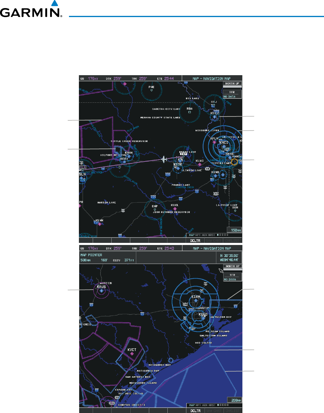
190-00928-04 Rev. A
Garmin G1000 Pilot’s Guide for the Beechcraft 200/B200 Series
201
FLIGHT MANAGEMENT
5.4 AIRSPACES
The G1000 can display the following types of airspaces: Class B/TMA, Class C/TCA, Class D, Restricted, MOA
(Military), Other Airspace, Air Defense Identification Zone (ADIZ), and Temporary Flight Restriction (TFR).
Figure 5-48 Airspaces
MOA (Military) Class D Airspace
Class B Airspace
TFR
Restricted Area
Class C Airspace Alert Area
ADIZ
Warning Area

Garmin G1000 Pilot’s Guide for the Beechcraft 200/B200 Series
190-00928-04 Rev. A202
FLIGHT MANAGEMENT
The Nearest Airspaces Page, Airspace Alerts Window, and Airspace Alerts on the PFD provide additional
information about airspaces and the location of the aircraft in relationship to them.
The Airspace Alerts Box allows the pilot to turn the controlled/special-use airspace message alerts on or off.
This does not affect the alerts listed on the Nearest Airspaces Page or the airspace boundaries depicted on the
Navigation Map Page. It simply turns on/off the warning provided when the aircraft is approaching or near an
airspace.
An altitude buffer is also provided which “expands” the vertical range above or below an airspace. For example,
if the buffer is set at 500 feet, and the aircraft is more than 500 feet above/below an airspace, an alert message is
not generated, but if the aircraft is less than 500 feet above/below an airspace and projected to enter it, the pilot
is notified with an alert message. The default setting for the altitude buffer is 200 feet.
Changing the altitude buffer distance setting:
1) Use the FMS Knob to select the AUX - System Setup Page.
2) Press the FMS Knob momentarily to activate the flashing cursor.
3) Turn the large FMS Knob to highlight the altitude buffer field in the Airspace Alerts Box.
4) Use the FMS Knob to enter an altitude buffer value and press the ENT Key.
5) Press the FMS Knob to remove the flashing cursor.
Turning an airspace alert on or off:
1) Use the FMS Knob to select the AUX - System Setup Page.
2) Press the FMS Knob momentarily to activate the flashing cursor.
3) Turn the large FMS Knob to highlight the desired field in the Airspace Alerts Box.
4) Turn the small FMS Knob clockwise to turn the airspace alert ON or counterclockwise to turn the alert OFF.
5) Press the FMS Knob to remove the flashing cursor.
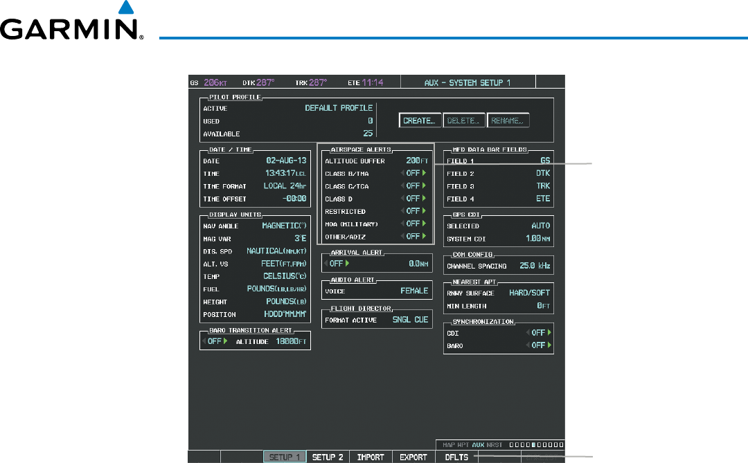
190-00928-04 Rev. A
Garmin G1000 Pilot’s Guide for the Beechcraft 200/B200 Series
203
FLIGHT MANAGEMENT
Figure 5-49 System Setup Page - Airspace Alerts
DFLTS Softkey
Airspace Alerts Box
- Airspace Altitude Buffer
- Alert On/Off
(Default Settings Shown)
Map ranges for the airspace boundaries are selected from the Aviation Group in the Map Setup Menu. See Table
5-2 for the default and maximum ranges for each type of airspace and the symbol used to define the airspace
area.
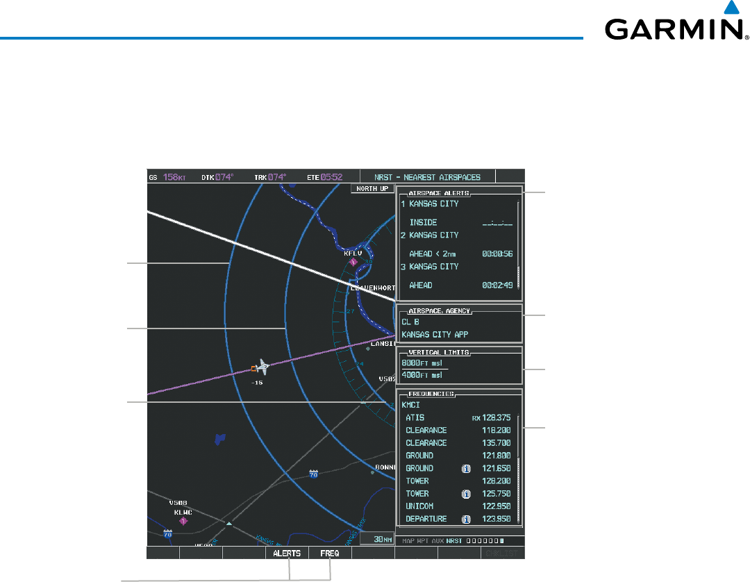
Garmin G1000 Pilot’s Guide for the Beechcraft 200/B200 Series
190-00928-04 Rev. A204
FLIGHT MANAGEMENT
The Nearest Airspaces Page can be used to quickly find airspaces close to the flight path. In addition, a selected
frequency associated with the airspace can be loaded from the Nearest Airspaces Page. In addition to displaying
a map of airspace boundaries and surrounding area, the Nearest Airspaces Page displays airspace information in
four boxes labeled ‘AIRSPACE ALERTS’, ‘AIRSPACE, AGENCY’, ‘VERTICAL LIMITS’, and ‘FREQUENCIES’.
Figure 5-50 Nearest Airspaces Page
Airspace Alerts Info
- Name
- Proximity (Ahead, Inside,
Ahead < 2nm, Within 2nm)
- Time till Intercept (only if
Ahead or Ahead < 2nm)
Airspace Vertical Limits
- Ceiling
- Floor
Airspace/Agency Info
- Airspace Type
- Controlling Agency
Softkeys
Airspace 1
Associated Frequencies
- Type
- Availability/Info
- Frequency
Airspace 2
Airspace 3
Airspace alerts and associated frequencies are shown in scrollable lists on the Nearest Airspaces Page. The
ALERTS and FREQ softkeys place the cursor in the respective list. The FREQ Softkey is enabled only if one or
more frequencies exist for a selected airspace.
Selecting and viewing an airspace alert with its associated information:
1) Select the Nearest Airspaces Page.
2) Select the ALERTS Softkey; or press the FMS Knob; or press the MENU Key, highlight ‘Select Alerts Window’,
and press the ENT Key. The cursor is placed in the ‘AIRSPACE ALERTS’ Box.
3) Select the desired airspace.
4) Press the FMS Knob to remove the flashing cursor.
190-00928-04 Rev. A
Garmin G1000 Pilot’s Guide for the Beechcraft 200/B200 Series
205
FLIGHT MANAGEMENT
Pressing the PFD ALERTS Softkey displays the message window on the PFD. The following airspace alerts are
displayed in the message window:
Message Comments
INSIDE ARSPC
– Inside airspace. The aircraft is inside the airspace.
ARSPC AHEAD
– Airspace ahead –
less than 10 minutes.
Special use airspace is ahead of aircraft. The aircraft penetrates the airspace within 10
minutes.
ARSPC NEAR
– Airspace near and
ahead. Special use airspace is near and ahead of the aircraft position.
ARSPC NEAR
– Airspace near –
less than 2 nm. Special use airspace is within 2 nm of the aircraft position.
Table 5-6 PFD Airspace Alert Messages
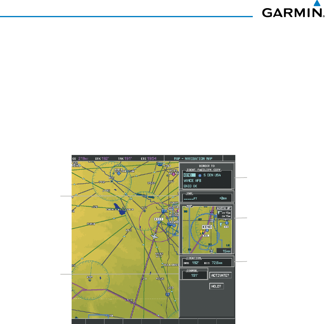
Garmin G1000 Pilot’s Guide for the Beechcraft 200/B200 Series
190-00928-04 Rev. A206
FLIGHT MANAGEMENT
5.5 DIRECT-TO-NAVIGATION
The Direct-to method of navigation, initiated by pressing the Direct-to Key on either the MFD or PFD, is
quicker to use than a flight plan when the desire is to navigate to a single point such as a nearby airport.
Once a direct-to is activated, the G1000 establishes a point-to-point course line from the present position to the
selected direct-to destination. Course guidance is provided until the direct-to is replaced with a new direct-to or
flight plan, or cancelled.
A vertical navigation (VNV) direct-to creates a descent path (and provides guidance to stay on the path) from
the current altitude to a selected altitude at the direct-to waypoint. Vertical navigation is based on barometric
altitudes, not on GPS altitude, and is used for cruise and descent phases of flight.
The Direct-to Window allows selection and activation of direct-to navigation. The Direct-to Window displays
selected direct-to waypoint data on the PFD and the MFD.
Figure 5-51 Direct-to Window - MFD
Direct-to Point Info
- Identifier/Symbol/Region
- Facility Name
- City
Location of Destination
- Bearing/Distance
Map of Selected Point
Desired Course
VNV Constraints
- Altitude at Arrival
- Along Track Offset
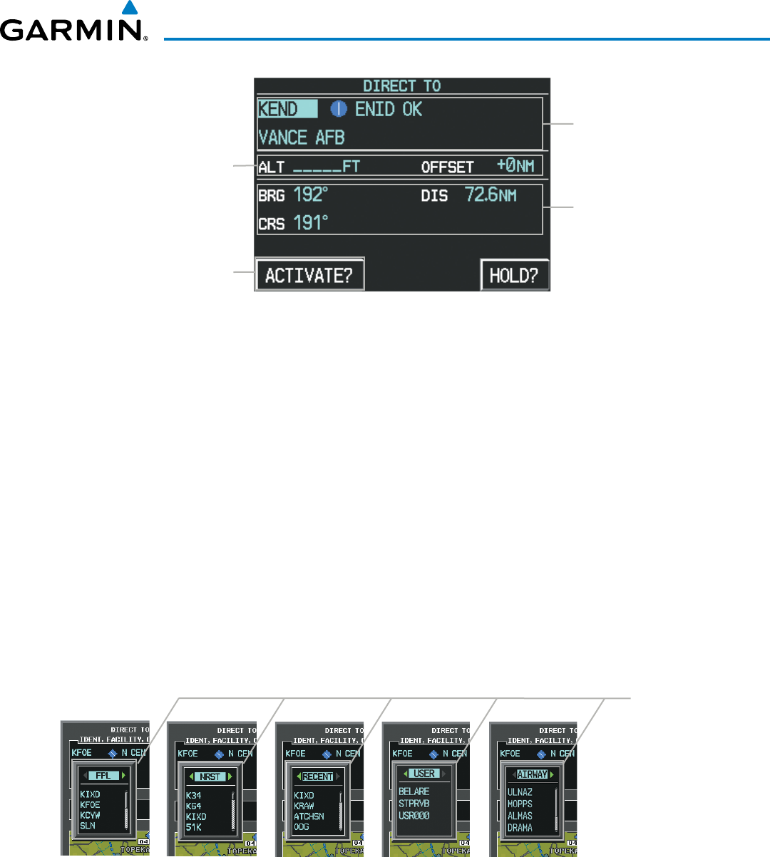
190-00928-04 Rev. A
Garmin G1000 Pilot’s Guide for the Beechcraft 200/B200 Series
207
FLIGHT MANAGEMENT
Figure 5-52 Direct-to Window - PFD
Direct-to Point Info
- Identifier/Symbol/City
- Facility Name
Activation Command
Direct-to Point Info
- Bearing/Distance
- Desired Course
VNV Constraints
- Altitude at Arrival
- Along Track Offset
Any waypoint can be entered as a direct-to destination from the Direct-to Window.
Entering a waypoint identifier, facility name, or city as a direct-to destination:
1) Press the Direct-to Key. The Direct-to Window is displayed (with the active flight plan wayoint as the default
selection or a blank waypoint field if no flight plan is active).
2) Turn the small FMS Knob clockwise to begin entering a waypoint identifier (turning it counter-clockwise brings
up the waypoint selection submenu - press the CLR Key to remove it), or turn the large FMS Knob to select the
facility name, or city field and turn the small FMS Knob to begin entering a facility name or city. If duplicate
entries exist for the entered facility or city name, additional entries can be viewed by turning the small FMS
Knob during the selection process.
3) Press the ENT Key. The ‘Activate?’ field is highlighted.
4) Press the ENT Key to activate the direct-to.
Any waypoint contained in the active flight plan can be selected as a direct-to waypoint from the Direct-to
Window, the Active Flight Plan Page, or the Active Flight Plan Window.
Figure 5-53 Waypoint Submenu
Waypoint Submenu
- Flight Plan Waypoints
- Nearest Airports
- Recent Waypoints
- User Waypoints
- Airway Waypoints
(only available when
active leg is part of an
airway)

Garmin G1000 Pilot’s Guide for the Beechcraft 200/B200 Series
190-00928-04 Rev. A208
FLIGHT MANAGEMENT
Selecting an active flight plan waypoint as a direct-to destination:
1) While navigating an active flight plan, press the Direct-to Key. The Direct-to Window is displayed with the
active flight plan waypoint as the default selection.
2) Turn the small FMS Knob counter-clockwise to display a list of flight plan waypoints (the FPL list is populated
only when navigating a flight plan).
3) Select the desired waypoint.
4) Press the ENT Key. The cursor is now displayed on ‘ACTIVATE?’.
5) Press the ENT Key again to activate the direct-to.
Or:
1) Select the Active Flight Plan Page on the MFD, or the Active Flight Plan Window on the PFD.
2) Select the desired waypoint.
3) Press the Direct-to Key.
4) Press the ENT Key. The cursor is now displayed on ‘ACTIVATE?’.
5) Press the ENT Key again to activate the direct-to.
Any NRST, RECENT, USER, or AIRWAY waypoint can be selected as a direct-to destination in the Direct-to
Window.
Selecting a NRST, RECENT, USER, or AIRWAY waypoint as a direct-to destination:
1) Press the Direct-to Key. The Direct-to Window is displayed (with the active flight plan destination as the
default selection or a blank destination if no flight plan is active).
2) Turn the small FMS Knob counter-clockwise to display a list of flight plan waypoints (the FPL list is populated
only when navigating a flight plan).
3) Turn the small FMS Knob clockwise to display the NRST, RECENT, USER, or AIRWAY waypoints.
4) Turn the large FMS Knob clockwise to select the desired waypoint.
5) Press the ENT Key. The cursor is now displayed on ‘ACTIVATE?’.
6) Press the ENT Key again to activate the direct-to.
The Direct-to Window can be displayed from any page and allows selection and activation of direct-to navigation.
If the direct-to is initiated from any page except the WPT pages, the default waypoint is the active flight plan
waypoint (if a flight plan is active) or a blank waypoint field. Direct-to requests on any WPT page defaults to the
displayed waypoint.
Selecting any waypoint as a direct-to destination:
1) Select the page or window containing the desired waypoint type and select the desired waypoint.
2) Press the Direct-to Key to display the Direct-to Window with the selected waypoint as the direct-to
destination.
3) Press the ENT Key. The cursor is now displayed on ‘ACTIVATE?’.
4) Press ENT again to activate the direct-to.

190-00928-04 Rev. A
Garmin G1000 Pilot’s Guide for the Beechcraft 200/B200 Series
209
FLIGHT MANAGEMENT
Selecting a nearby airport as a direct-to destination:
1) Select the NRST Softkey on the PFD; or turn the FMS Knob to display the Nearest Airports Page and press the
FMS Knob.
2) Select the desired airport (the nearest one is already selected).
3) Press the Direct-to Key.
4) Press the ENT Key. The cursor is now displayed on ‘ACTIVATE?’.
5) Press the ENT Key again to activate the direct-to.
Direct-to destinations may also be selected by using the pointer on the navigation map pages. If no airport,
NAVAID, or user waypoint exists at the desired location, a temporary waypoint named ‘MAPWPT’ is automatically
created at the location of the map arrow.
Selecting a waypoint as a direct-to destination using the pointer:
1) From a navigation map page, press the Joystick to display the pointer.
2) Move the Joystick to place the pointer at the desired destination location.
3) If the pointer is placed on an existing airport, NAVAID, or user waypoint, the waypoint name is highlighted.
4) Press the Direct-to Key to display the Direct-to Window with the selected point entered as the direct-to
destination.
5) Press the ENT Key. The cursor is now displayed on ‘ACTIVATE?’.
6) Press the ENT Key again to activate the direct-to.
Cancelling a Direct-to:
1) Press the Direct-to Key to display the Direct-to Window.
2) Press the MENU Key.
3) With ‘Cancel Direct-To NAV’ highlighted, press the ENT Key. If a flight plan is still active, the G1000 resumes
navigating the flight plan along the closest leg.
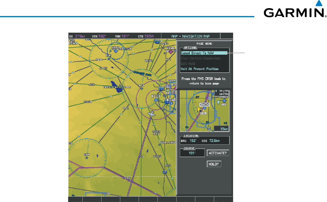
Garmin G1000 Pilot’s Guide for the Beechcraft 200/B200 Series
190-00928-04 Rev. A210
FLIGHT MANAGEMENT
Figure 5-54 Direct-to Window - Cancelling Direct-to Navigation
Page Menu
- Cancel Direct-To NAV
- Hold At Present Position
When navigating a direct-to, the G1000 sets a direct great circle course to the selected destination. The course
to a destination can also be manually selected using the course field (‘COURSE’) on the Direct-to Window.
Selecting a manual direct-to course:
1) Press the Direct-to Key. The Direct-to Window is displayed with the destination field highlighted.
2) Highlight the course field.
3) Enter the desired course.
4) Press the ENT Key. The cursor is now displayed on ‘ACTIVATE?’.
5) Press the ENT Key again to activate the direct-to.
Reselecting the direct course from the current position:
1) Press the Direct-to Key. The Direct-to Window is displayed with the destination field highlighted.
2) Press the ENT Key. The cursor is now displayed on ‘ACTIVATE?’.
3) Press the ENT Key again to activate the direct-to.
A direct-to with altitude constraints creates a descent path (and provides guidance to stay on the path) from the
aircraft’s current altitude to the altitude of the direct-to waypoint. The altitude is reached at the waypoint, or at the
specified distance along the flight path if an offset distance has been entered. All VNV altitudes prior to the direct-
to destination are removed from the active flight plan upon successful activation of a direct-to destination that is

190-00928-04 Rev. A
Garmin G1000 Pilot’s Guide for the Beechcraft 200/B200 Series
211
FLIGHT MANAGEMENT
part of the active flight plan. All VNV altitudes following the direct-to waypoint are retained. See the section on
Vertical Navigation for more information regarding the use and purpose of VNV altitudes and offset distances.
Entering a VNV altitude and along-track offset for the waypoint:
1) Press the Direct-to Key to display the Direct-to Window.
2) Turn the large FMS Knob to place the cursor over the ‘VNV’ altitude field.
3) Enter the desired altitude.
4) Press the ENT Key. The option to select MSL or AGL is now displayed.
5) Turn the small FMS Knob to select ‘MSL’ or ‘AGL’.
6) Press the ENT Key. The cursor is now flashing in the VNV offset distance field.
7) Enter the desired along-track distance before the waypoint.
8) Press the ENT Key. The ‘Activate?’ field is highlighted.
9) Press the ENT Key to activate.
Removing a VNV altitude constraint:
1) Press the Direct-to Key to display the Direct-to Window.
2) Press the MENU Key.
3) With ‘Clear Vertical Constraints’ highlighted, press the ENT Key.
Figure 5-55 Direct-to Window - Clearing Vertical Constraints
Page Menu
- Clear Vertical Navigation
Constraints
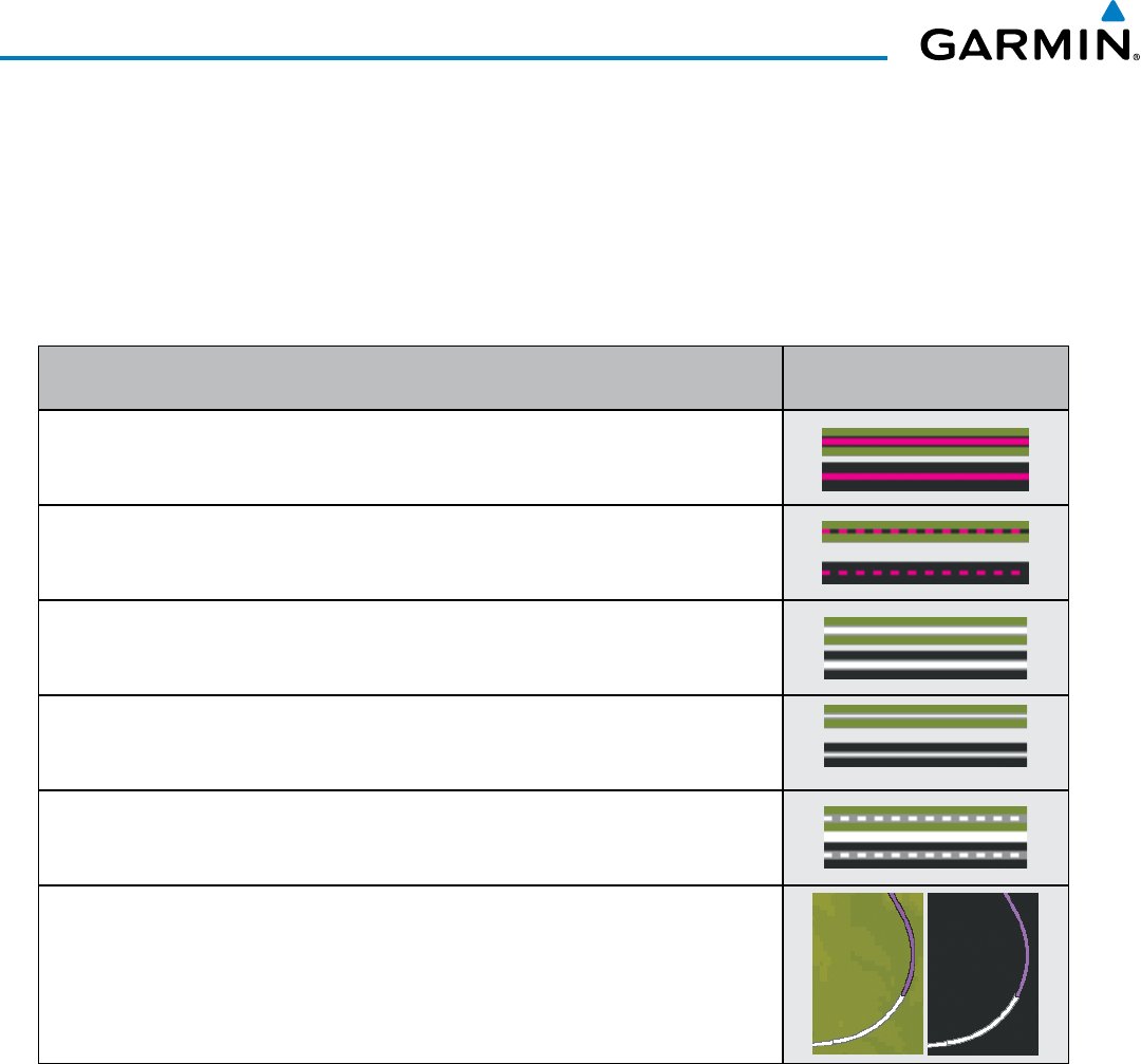
Garmin G1000 Pilot’s Guide for the Beechcraft 200/B200 Series
190-00928-04 Rev. A212
FLIGHT MANAGEMENT
5.6 FLIGHT PLANNING
Flight planning on the G1000 consists of building a flight plan by entering waypoints one at a time, adding
waypoints along airways, and inserting departures, airways, arrivals, or approaches as needed. The G1000 allows
flight planning information to be entered from either the MFD or PFD. The flight plan is displayed on maps using
different line widths, colors, and types, based on the type of leg and the segment of the flight plan currently being
flown (departure, enroute, arrival, approach, or missed approach).
Flight Plan Leg Type Symbol
Active Course Leg (TOPO On)
Active Course Leg (TOPO Off)
Active Heading Leg (TOPO On)
Active Heading Leg (TOPO Off)
Course Leg in the current flight segment (TOPO On)
Course Leg in the current flight segment (TOPO Off)
Course Leg not in the current flight segment (TOPO On)
Course Leg not in the current flight segment (TOPO Off)
Heading Leg (TOPO On)
Heading Leg (TOPO Off)
Turn Anticipation Arc (TOPO On/TOPO Off)
Table 5-7 Flight Plan Leg Symbols
Up to 99 flight plans with up to 99 waypoints each can be created and stored in memory. One flight plan can be
activated at a time and becomes the active flight plan. The active flight plan is erased when the system is turned
off and overwritten when another flight plan is activated. When storing flight plans with an approach, departure,
or arrival, the G1000 uses the waypoint information from the current database to define the waypoints. If the
database is changed or updated, the G1000 automatically updates the information if the procedure has not been
modified. If an approach, departure, or arrival procedure is no longer available, the procedure is deleted from the
affected stored flight plan(s), and an alert is displayed (see Miscellaneous Messages in Appendix A) advising that
one or more stored flight plans need to be edited.
Whenever an approach, departure, or arrival procedure is loaded into the active flight plan, a set of approach,
departure, or arrival waypoints is inserted into the flight plan along with a header line describing the instrument
procedure the pilot selected. The original enroute portion of the flight plan remains active (unless an instrument
procedure is activated) when the procedure is loaded.
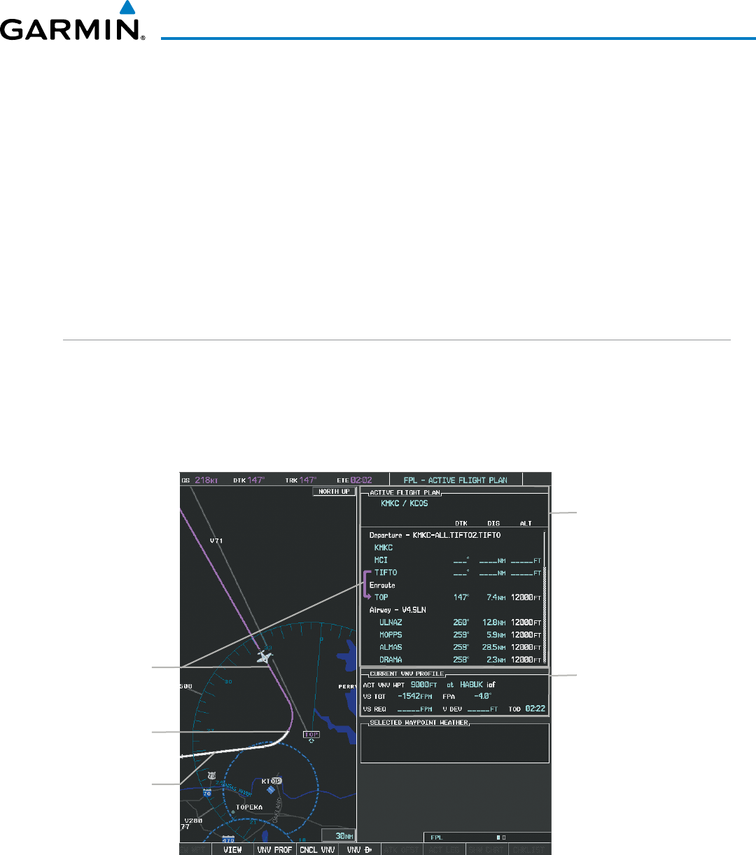
190-00928-04 Rev. A
Garmin G1000 Pilot’s Guide for the Beechcraft 200/B200 Series
213
FLIGHT MANAGEMENT
When the database is updated, the airways need to be reloaded also. Each airway segment is reloaded from
the database given the entry waypoint, the airway identifier and the exit waypoint. This reloads the sequence of
waypoints between the entry and exit waypoints (the sequence may change when the database is updated). The
update of an airway can fail during this process. If that happens, the airway waypoints are changed to regular
(non-airway) flight plan waypoints, and an alert is displayed (see Miscellaneous Messages in Appendix A).
The following could cause the airway update to fail:
• Airway identifier, entry waypoint or exit waypoint not found in the new database.
• Airway entry/exit waypoint is not an acceptable waypoint for the airway – either the waypoint is no longer on
the airway, or there is a new directional restriction that prevents it being used.
• Loading the new airway sequence would exceed the capacity of the flight plan.
FLIGHT PLAN CREATION
There are three methods to create or modify a flight plan:
• Active Flight Plan Page on the MFD (create/modify the active flight plan)
• Active Flight Plan Window on the PFD (create/modify the active flight plan)
• Flight Plan Catalog Page on the MFD (create/modify a stored flight plan)
Figure 5-56 Active Flight Plan Page
Active FPL Waypoint List
- Comment
- Procedure Header
- Waypoint Identifier
- Airway Identifier
- Desired Track to Waypoint
- Distance to Waypoint
- Waypoint Altitude Constraint
Vertical Navigation Profile
- Active Vertical WPT Alt/ID
- Vertical Speed Target
- Flight Path Angle
- Vertical Speed Target
- Time to Top of Descent
- Vertical Deviation
Active Flight
Plan Leg
Turn Anticipation
Arc
Non-Active,
Flight Plan Leg
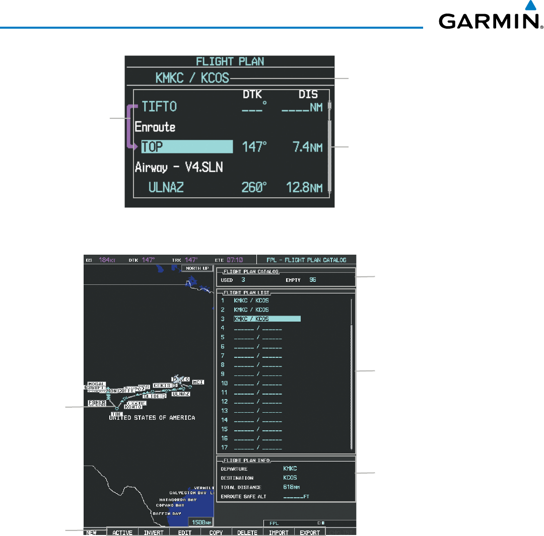
Garmin G1000 Pilot’s Guide for the Beechcraft 200/B200 Series
190-00928-04 Rev. A214
FLIGHT MANAGEMENT
Active Flight Plan Comment
Figure 5-57 Active Flight Plan Window on PFD
Active Flight
Plan Leg
Active Flight Plan Waypoint List
- Waypoint ID
- Desired Track to Waypoint
- Distance to Waypoint
- Airway Identifier
Figure 5-58 Flight Plan Catalog Page
Flight Plan List
- Comment
Selected FPL Info
- Departure Waypoint
- Destination Waypoint
- Total Flight Plan Distance
- Enroute Safe Altitude
Catalog Contents
- # Used
- # Empty
Softkeys
Selected
Flight Plan
Map

190-00928-04 Rev. A
Garmin G1000 Pilot’s Guide for the Beechcraft 200/B200 Series
215
FLIGHT MANAGEMENT
The active flight plan is listed on the active Flight Plan Page on the MFD, and in the Active Flight Plan
Window on the PFD. It is the flight plan to which the G1000 is currently providing guidance, and is shown
on the navigation maps. Stored flight plans are listed on the Flight Plan Catalog Page, and are available for
activation (becomes the active flight plan).
Creating an active flight plan:
1) Press the FPL Key.
2) Press the FMS Knob to activate the cursor (only on MFD).
3) Turn the small FMS Knob to display the Waypoint Information Window. (Turning it clockwise displays a blank
Waypoint Information Window, turning it counter-clockwise displays the Waypoint Information Window
with a waypoint selection submenu allowing selection of active flight plan, nearest, recent, user, or airway
waypoints).
4) Enter the identifier, facility, or city name of the departure waypoint or select a waypoint from the submenu of
waypoints and press the ENT Key. The active flight plan is modified as each waypoint is entered.
5) Repeat step numbers 3 and 4 to enter each additional flight plan waypoint.
6) When all waypoints have been entered, press the FMS Knob to remove the cursor.
Creating a stored flight plan:
1) Press the FPL Key.
2) Turn the small FMS Knob clockwise to display the Flight Plan Catalog Page.
3) Select the NEW Softkey; or press the MENU Key, highlight ‘Create New Flight Plan’, and press the ENT Key to
display a blank flight plan for the first empty storage location.
4) Turn the small FMS Knob to display the Waypoint Information Window. (Turning it clockwise displays a blank
Waypoint Information Window, turning it counter-clockwise displays the Waypoint Information Window
with a waypoint selection submenu allowing selection of active flight plan, nearest, recent, user, or airway
waypoints).
5) Enter the identifier, facility, or city name of the departure waypoint or select a waypoint from the submenu of
waypoints and press the ENT Key.
6) Repeat step numbers 4 and 5 to enter each additional flight plan waypoint.
7) When all waypoints have been entered, press the FMS Knob to return to the Flight Plan Catalog Page. The new
flight plan is now in the list.
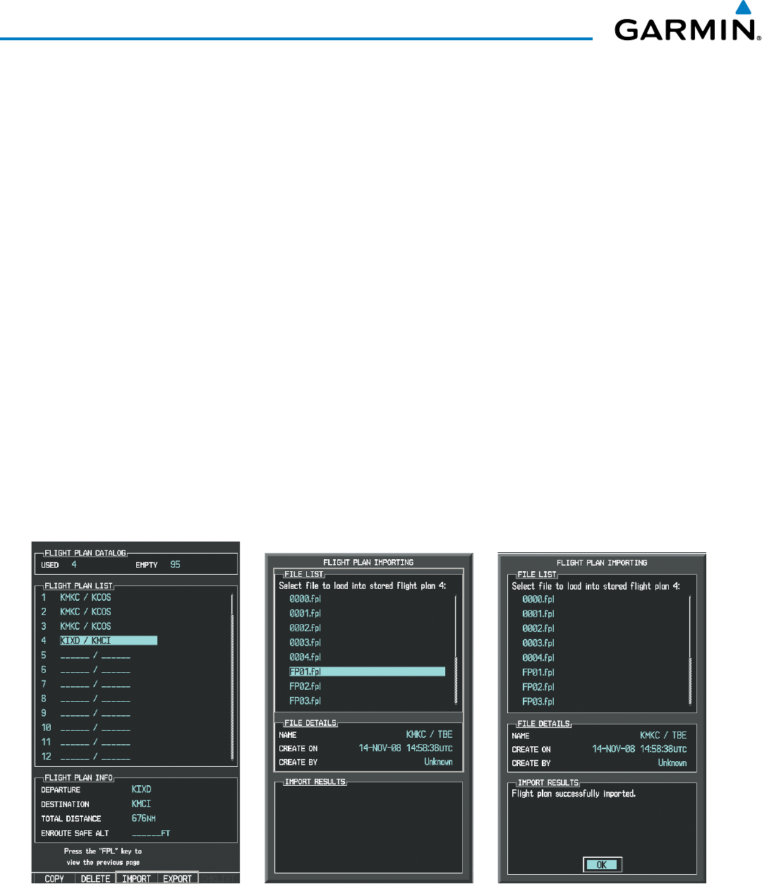
Garmin G1000 Pilot’s Guide for the Beechcraft 200/B200 Series
190-00928-04 Rev. A216
FLIGHT MANAGEMENT
Flight plans can be imported from an SD Card or exported to an SD Card from the Stored Flight Plan Page.
Importing a Flight Plan from an SD Card
1) Insert the SD card containing the flight plan in the top card slot on the MFD.
2) Press the FPL Key to display the Active Flight Plan Page on the MFD.
3) Turn the small FMS Knob to select the Flight Plan Catalog Page.
4) Press the FMS Knob to activate the cursor.
5) Turn either FMS Knob to highlight an empty or existing flight plan.
6) Press the IMPORT Softkey; or press the MENU Key, select “Import Flight Plan”, and press the ENT Key.
If an empty slot is selected, a list of the available flight plans on the SD card will be displayed.
Or:
If an existing flight plan is selected, an “Overwrite existing flight plan? OK or CANCEL” prompt is displayed.
Press the ENT Key to choose to overwrite the selected flight plan and see the list of available flight plans on the
SD card. If overwriting the existing flight plan is not desired, select “CANCEL” using the FMS Knob, press the
ENT Key, select another flight plan slot, and press the IMPORT Softkey again.
7) Turn the small FMS Knob to highlight the desired flight plan for importing.
8) Press the ENT Key to initiate the import.
9) Press the ENT Key again to confirm the import.
Figure 5-59 Flight Plan Import
Import/Export Softkeys List of Flight Plans to Import &
Details for the Selected File
Import Successful
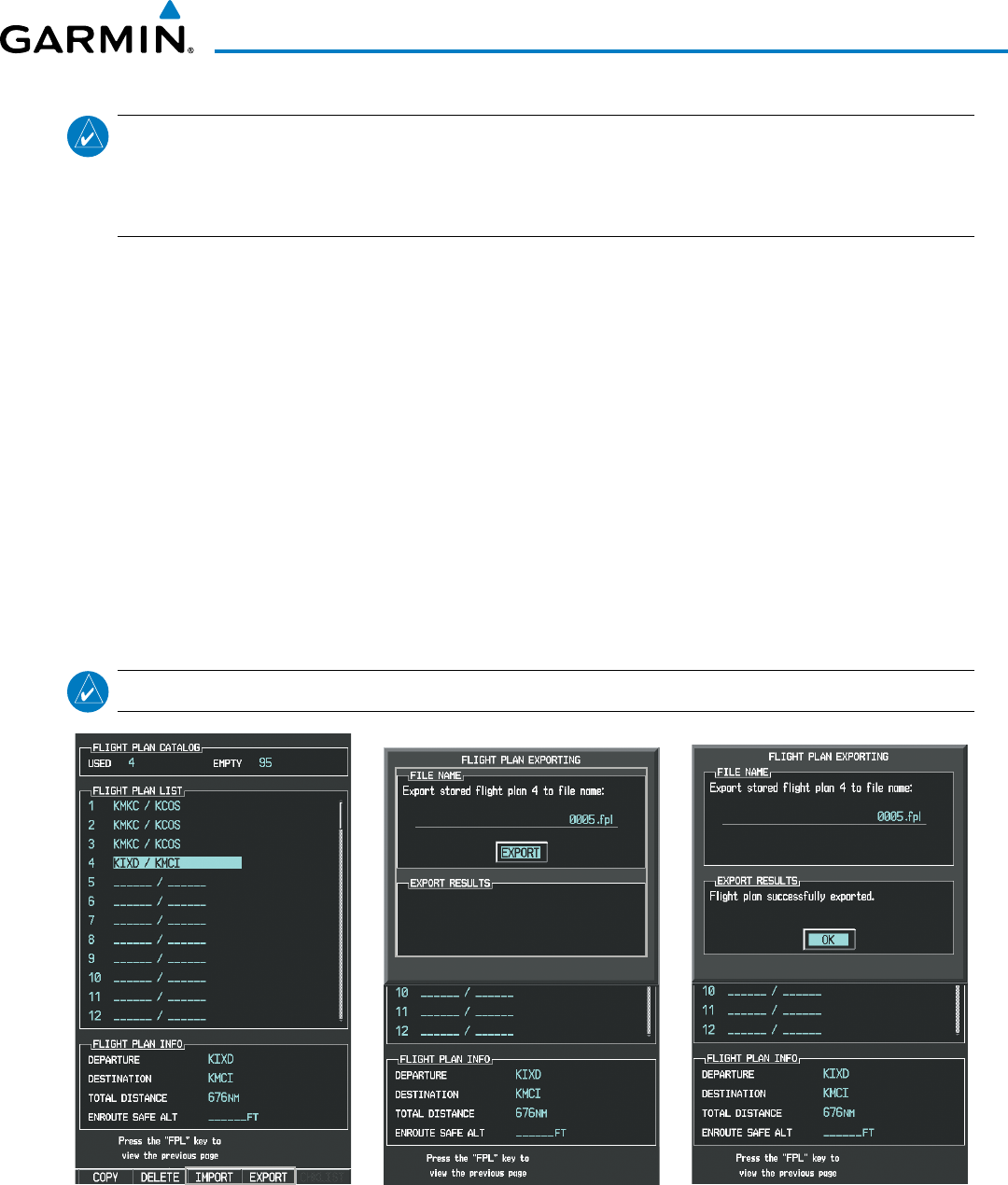
190-00928-04 Rev. A
Garmin G1000 Pilot’s Guide for the Beechcraft 200/B200 Series
217
FLIGHT MANAGEMENT
NOTE: If the imported flight plan contains a waypoint with a name that duplicates the name of a waypoint
already stored on the system, the system compares the coordinates of the imported waypoint with those of
the existing waypoint. If the coordinates are different, the imported waypoint is automatically renamed by
adding characters to the end of the name.
Exporting a Flight Plan to an SD Card
1) Insert the SD card into the top card slot on the MFD.
2) Press the FPL Key to display the Active Flight Plan Page on the MFD.
3) Turn the small FMS Knob to select the Flight Plan Catalog Page.
4) Press the FMS Knob to activate the cursor.
5) Turn the large FMS Knob to highlight the flight plan to be exported.
6) Press the EXPORT Softkey; or press the MENU Key, select “Export Flight Plan”.
7) If desired, change the name for the exported file by turning the large FMS Knob to the left to highlight the
name, then use the small and large FMS knobs to enter the new name, and press the ENT Key.
8) Press the ENT Key to initiate the export.
9) Press the ENT Key to confirm the export.
NOTE: The exported flight plan will not contain any procedures or airways.
Figure 5-60 Flight Plan Export
Import/Export Softkeys Stored Flight Plan to be Exported &
Exported Flight Plan Name
Export Successful
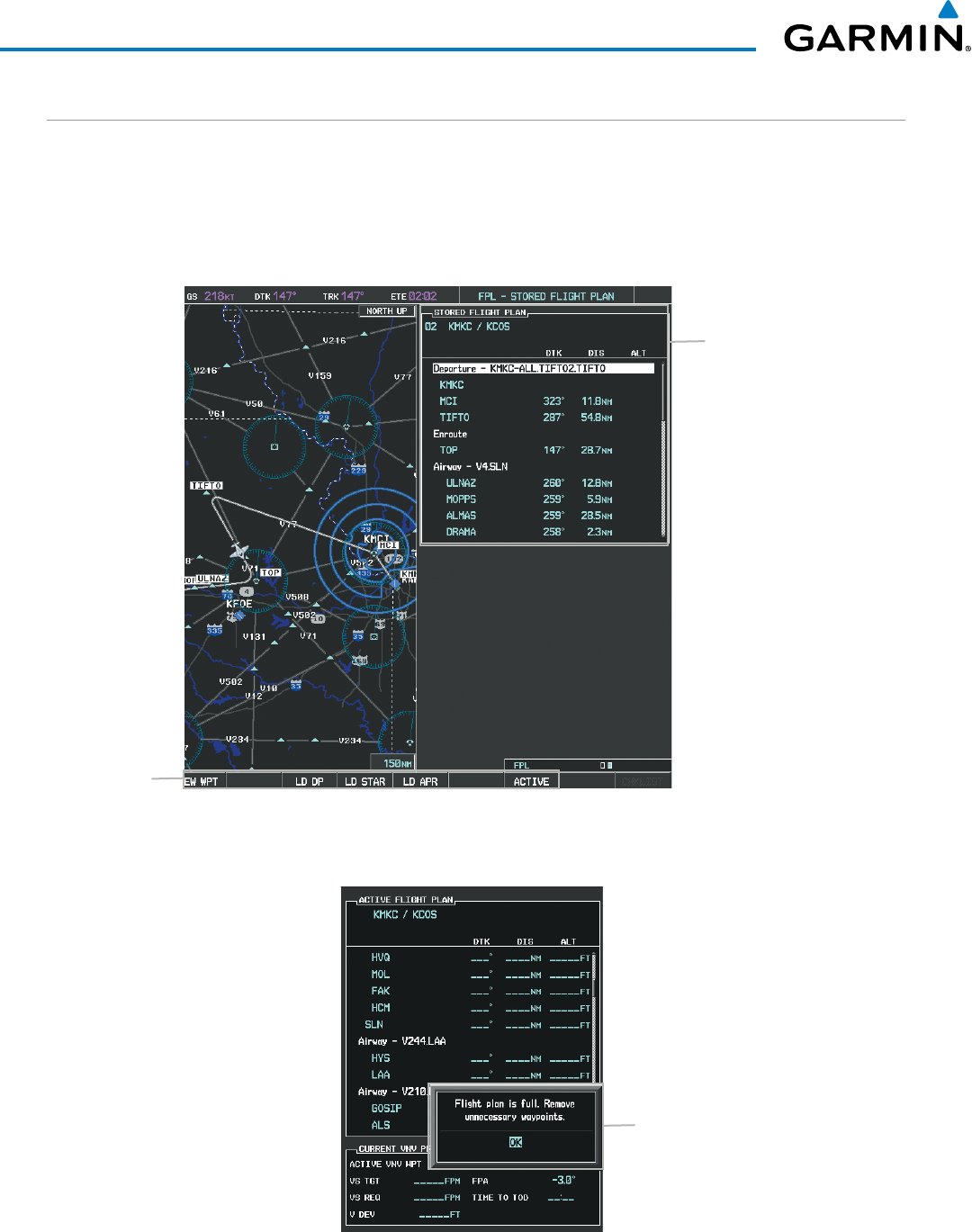
Garmin G1000 Pilot’s Guide for the Beechcraft 200/B200 Series
190-00928-04 Rev. A218
FLIGHT MANAGEMENT
ADDING WAYPOINTS TO AN EXISTING FLIGHT PLAN
Waypoints can be added to the active flight plan or any stored flight plan. Choose the flight plan, select the
desired point of insertion, enter the waypoint, and it is added in front of the selected waypoint. Flight plans
are limited to 99 waypoints (including waypoints within airways and procedures). If the number of waypoints
in the flight plan exceeds 99, the message “Flight plan is full. Remove unnecessary waypoints.” appears and the
new waypoint(s) are not added to the flight plan.
Figure 5-61 Stored Flight Plan Page
Stored Flight Plan Selected
- Memory Slot
- Comment
- Procedure Identifier
- Waypoint Identifier
- Airway Identifier
- Desired Track to Waypoint
- Distance to Waypoint
- Waypoint Altitude Constraint
Softkeys
Figure 5-62 Active Flight Plan Page - FPL Full
Flight Plan Full Message
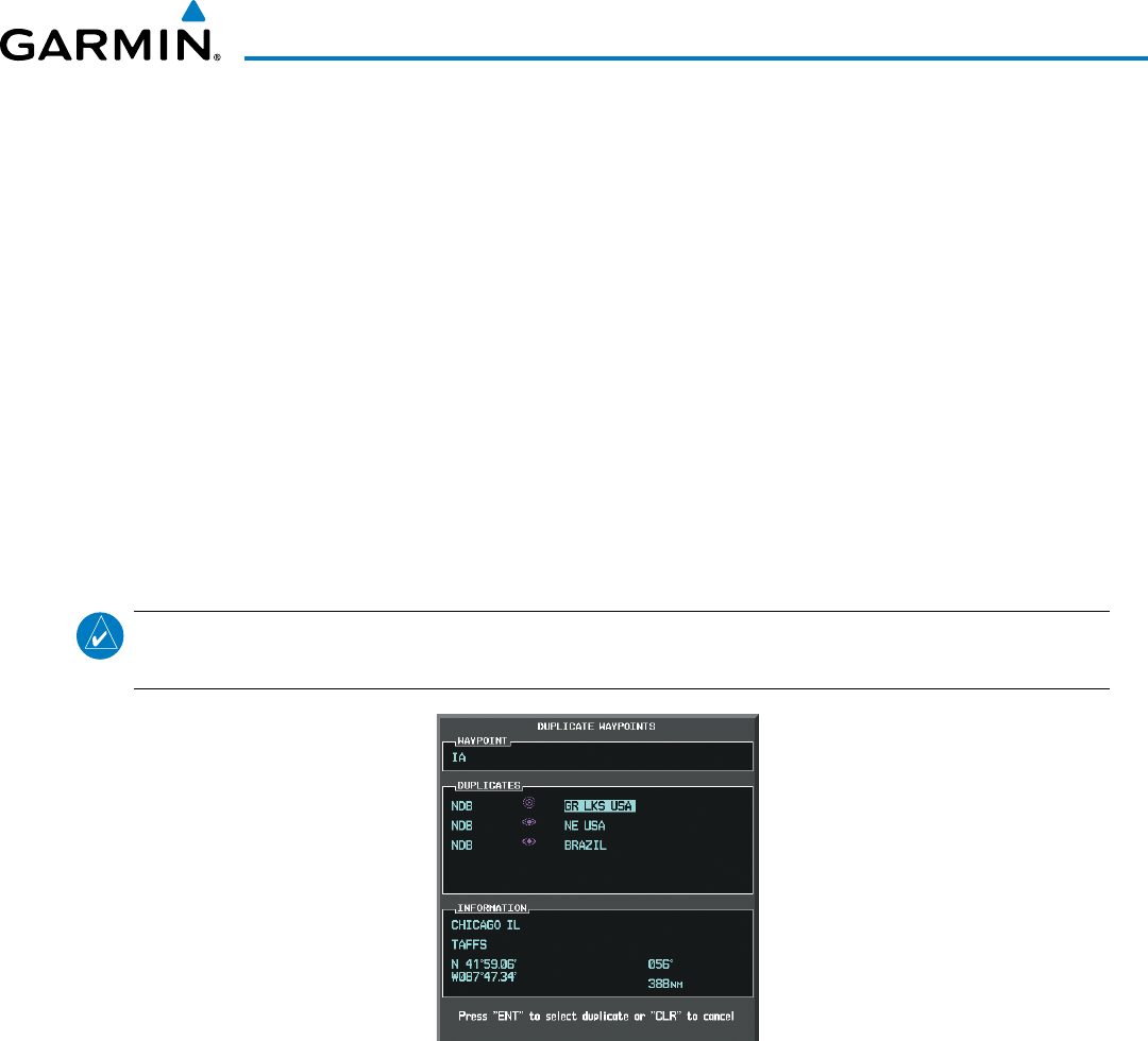
190-00928-04 Rev. A
Garmin G1000 Pilot’s Guide for the Beechcraft 200/B200 Series
219
FLIGHT MANAGEMENT
Adding a waypoint to a stored flight plan:
1) On the Flight Plan Catalog Page, press the FMS Knob to activate the cursor.
2) Highlight the desired flight plan.
3) Select the EDIT Softkey; or press the ENT Key, turn the large FMS Knob clockwise to select “EDIT” and press
the ENT Key. The Stored Flight Plan Page is displayed.
4) Select the point in the flight plan to add the new waypoint. The new waypoint is placed directly in front of the
highlighted waypoint.
5) Turn the small FMS Knob to display the Waypoint Information Window. (Turning it clockwise displays a blank
Waypoint Information Window, turning it counter-clockwise displays the Waypoint Information Window
with a waypoint selection submenu allowing selection of active flight plan, nearest, recent, user, or airway
waypoints).
6) Enter the identifier, facility, or city name of the waypoint or select a waypoint from the submenu of waypoints
and press the ENT Key. The new waypoint now exists in the flight plan.
NOTE: If the identifier entered in the Waypoint Information Window has duplicates, a Duplicate Waypoint
Window is displayed. Use the FMS Knob to select the correct waypoint.
Figure 5-63 Duplicate Waypoints Window
Adding a waypoint to the active flight plan:
1) Press the FPL Key.
2) Press the FMS Knob to activate the cursor (not required on the PFD).
3) Select the point in the flight plan before which to add the new waypoint. The new waypoint is placed directly
in front of the highlighted waypoint.
4) Turn the small FMS Knob to display the Waypoint Information Window. (Turning it clockwise displays a blank
Waypoint Information Window, turning it counter-clockwise displays the Waypoint Information Window
with a waypoint selection submenu allowing selection of active flight plan, nearest, recent, user, or airway
waypoints).
5) Enter the identifier, facility, or city name of the waypoint or select a waypoint from the submenu of waypoints
and press the ENT Key. The active flight plan is modified as each waypoint is entered.
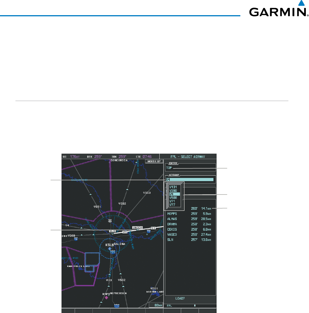
Garmin G1000 Pilot’s Guide for the Beechcraft 200/B200 Series
190-00928-04 Rev. A220
FLIGHT MANAGEMENT
Creating and adding user waypoints to the active flight plan:
1) Press the Joystick to activate the panning function on the Active Flight Plan Page and pan to the map location
of the desired user waypoint.
2) Select the LD WPT Softkey; or press the MENU Key, select ‘Load Waypoint’, and press the ENT Key. The user
waypoint is created with a name of USRxxx (using the next available in sequence) and is added to the end of
the active flight plan.
ADDING AIRWAYS TO A FLIGHT PLAN
Airways can be added to the active flight plan or any stored flight plan. Choose a flight plan (add the desired
airway entry point if not already in the flight plan), select the waypoint after the desired airway entry point,
select the airway, and it is added in front of the selected waypoint. An airway can only be loaded if there is a
waypoint in the flight plan that is part of the desired airway and is not part of an arrival or approach procedure.
The G1000 also anticipates the desired airway and exit point based on loaded flight plan waypoints.
Figure 5-64 Select Airway Page - Selecting Airway
Airway Entry Waypoint
Selected Airway
Airways Available at TOP
Airway Waypoint
Sequence
Preview of
Selected Airway
Adding an airway to a flight plan:
1) Press the FPL Key.
2) Press the FMS Knob to activate the cursor (not required on the PFD).
3) Turn the large FMS Knob to highlight the waypoint after the desired airway entry point. If this waypoint is not
a valid airway entry point, a valid entry point should be entered at this time.
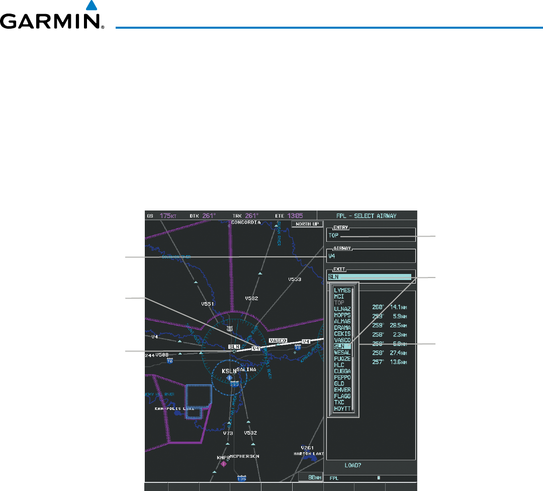
190-00928-04 Rev. A
Garmin G1000 Pilot’s Guide for the Beechcraft 200/B200 Series
221
FLIGHT MANAGEMENT
4) Turn the small FMS Knob one click clockwise and select the LD AIRWY Softkey, or press the MENU Key and
select “Load Airway”. The Select Airway Page is displayed. The LD AIRWY Softkey or the “Load Airway” menu
item is available only when a valid airway entry waypoint has been chosen (the waypoint ahead of the cursor
position).
5) Turn the FMS Knob to select the desired airway from the list, and press the ENT Key. Low altitude airways are
shown first in the list, followed by “all” altitude airways, and then high altitude airways.
6) Turn the FMS Knob to select the desired airway exit point from the list, and press the ENT Key. ‘LOAD?’ is
highlighted.
7) Press the ENT Key. The system returns to editing the flight plan with the new airway inserted.
Figure 5-65 Select Airway Page - Selecting Exit Point
Airway Entry Waypoint
Selected Airway
Airway Exit Points
Available
Selected Exit Point
Selected Airway Exit
Point
Preview of
Selected Airway
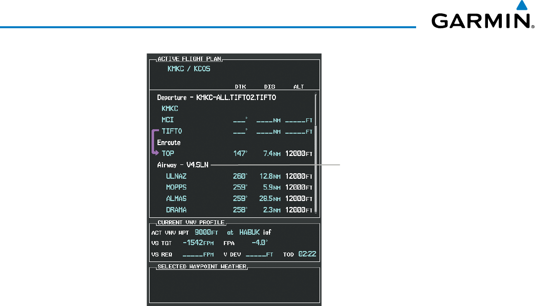
Garmin G1000 Pilot’s Guide for the Beechcraft 200/B200 Series
190-00928-04 Rev. A222
FLIGHT MANAGEMENT
Figure 5-66 Active Flight Plan Page - Airway Inserted
Inserted Airway Header
- Airway Identifier: [airway
identifier].[exit waypoint identifier]
(e.g., V4.SLN)
RESTRICTIONS ON ADDING AIRWAYS
Some airways have directional restrictions on all or part of the route. For example, Airway “A2” in Europe
has a directional restriction over the whole route such that it can be flown only in the direction MTD-ABB-
BNE-DEVAL.
Airway “UR975” in North Africa has more complicated directional restrictions within the list of airway
waypoints AMANO, VAKOR, LIBRO, NELDA, DIRKA, GZO, KOSET, and SARKI:
• Starting from AMANO, the airway can be flown only to LIBRO.
• Starting from SARKI, the airway can be flown only to LIBRO.
• Between NELDA and GZO, the airway can be flown in either direction.
In the US, airways that are “one-way” for specified hours of operation are not uncommon. These airways
are always bidirectional in the G1000 database.
The system only allows correct airway sequences to be inserted. If the pilot subsequently inverts the flight
plan, the system inverts the airway waypoint sequence and removes the airway header.
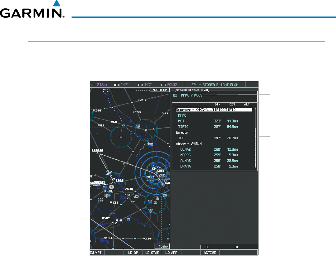
190-00928-04 Rev. A
Garmin G1000 Pilot’s Guide for the Beechcraft 200/B200 Series
223
FLIGHT MANAGEMENT
ADDING PROCEDURES TO A STORED FLIGHT PLAN
The G1000 allows the pilot to insert pre-defined instrument procedures from the navigation database into a
flight plan. The procedures are designed to facilitate routing of traffic leaving an airport (departure), arriving at
an airport (arrival), and landing at an airport (approach). See the procedures section for more details.
Figure 5-67 Stored Flight Plan Page
Flight Plan Name
Flight Plan Waypoint
List
Softkeys
Load Departure -
Load Arrival -
Load Approach -
Activate Flight Plan
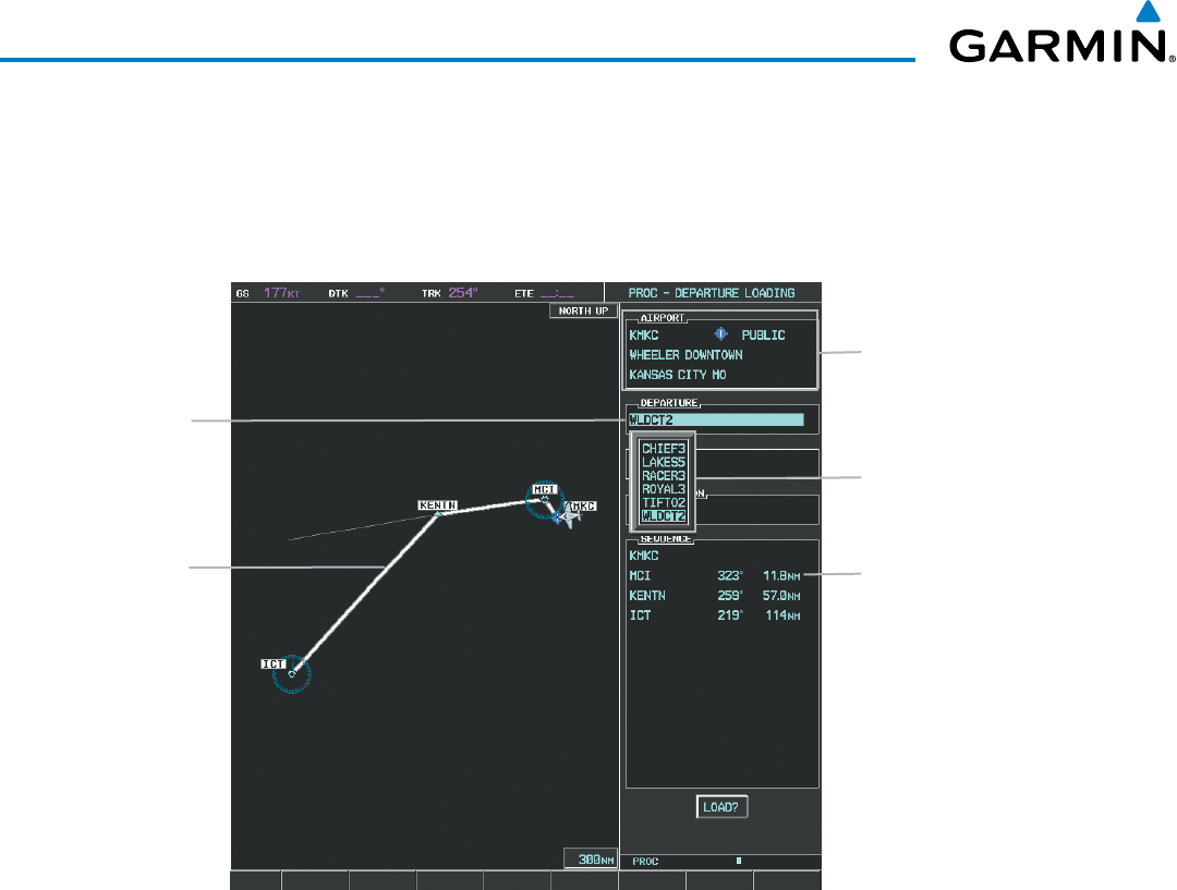
Garmin G1000 Pilot’s Guide for the Beechcraft 200/B200 Series
190-00928-04 Rev. A224
FLIGHT MANAGEMENT
DEPARTURE (DP)
A Departure Procedure (DP) is loaded at the departure airport in the flight plan. Only one departure can
be loaded at a time in a flight plan. The route is defined by selection of a departure, the transition waypoints,
and a runway.
Figure 5-68 Departure Loading Page - Selecting the Departure
Departure Airport
Selected
Departure
Departures Available at
KMKC
Departure Waypoint
Sequence
Preview of
Selected
Departure
Loading a departure procedure into a stored flight plan:
1) Select a stored flight plan from the Flight Plan Catalog Page.
2) Select the EDIT Softkey; or press the MENU Key, select ‘Edit Flight Plan’, and press the ENT Key. The Stored
Flight Plan Page is displayed.
3) Select the LD DP Softkey; or press the MENU Key, select “Load Departure”, and press the ENT Key. The
Departure Loading Page is displayed.
4) Select a departure. Press the ENT Key.
5) Select a runway served by the selected departure, if required. Press the ENT Key.
6) Select a transition for the selected departure. Press the ENT Key.
7) Press the ENT Key to load the selected departure procedure.
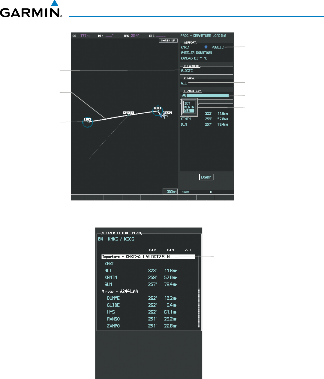
190-00928-04 Rev. A
Garmin G1000 Pilot’s Guide for the Beechcraft 200/B200 Series
225
FLIGHT MANAGEMENT
Figure 5-69 Departure Loading Page - Selecting Transition
Departure Airport
Selected
Departure
Departure Transition Points
Available
Selected Runway
Selected
Departure End
Point
Preview of
Selected
Departure
Selected Transition
Figure 5-70 Stored Flight Plan Page - Departure Inserted
Inserted Departure Header
- Departure Identifier: [departure
airport]-[departure runway].
[departure transition].
[departure end point]
(e.g., KMKC-ALL.WLDCT2.SLN)
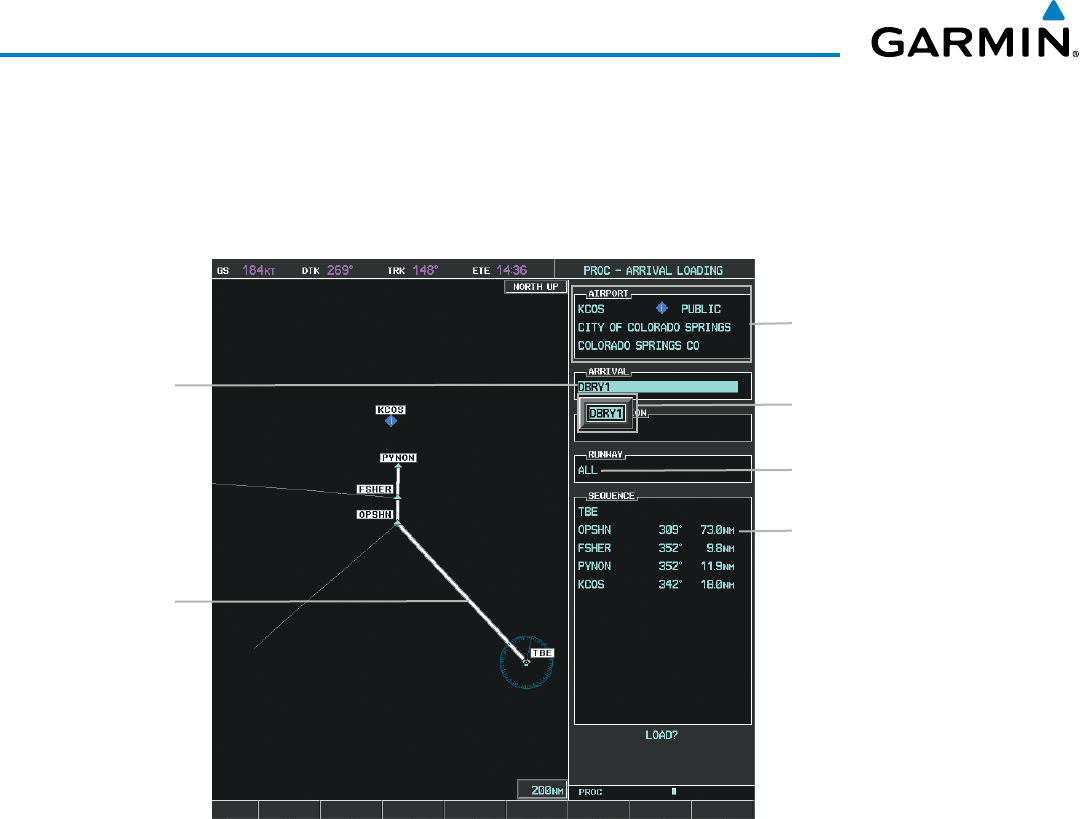
Garmin G1000 Pilot’s Guide for the Beechcraft 200/B200 Series
190-00928-04 Rev. A226
FLIGHT MANAGEMENT
ARRIVAL (STAR)
A Standard Terminal Arrival (STAR) is loaded at the destination airport in the flight plan. Only one arrival
can be loaded at a time in a flight plan. The route is defined by selection of an arrival, the transition waypoints,
and a runway.
Figure 5-71 Arrival Loading Page - Selecting the Arrival
Destination Airport
Selected Arrival Arrivals Available at KCOS
Arrival Waypoint Sequence
Preview of
Selected Arrival
Selected Runway
Loading an arrival procedure into a stored flight plan:
1) Select a stored flight plan from the Flight Plan Catalog Page.
2) Select the EDIT Softkey; or press the MENU Key, select ‘Edit Flight Plan’, and press the ENT Key. The Stored
Flight Plan Page is displayed.
3) Select the LD STAR Softkey; or press the MENU Key, select “Load Arrival”, and press the ENT Key. The Arrival
Loading Page is displayed.
4) Select an arrival. Press the ENT Key.
5) Select a transition for the selected arrival. Press the ENT Key.
6) Select a runway served by the selected arrival, if required. Press the ENT Key.
7) Press the ENT Key to load the selected arrival procedure.
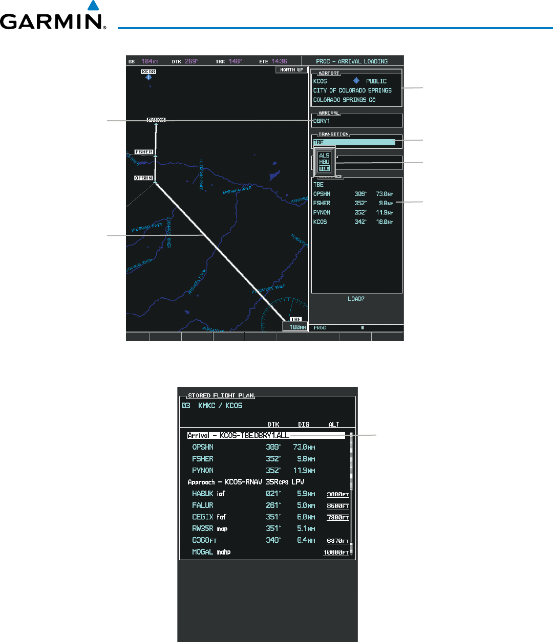
190-00928-04 Rev. A
Garmin G1000 Pilot’s Guide for the Beechcraft 200/B200 Series
227
FLIGHT MANAGEMENT
Figure 5-72 Arrival Loading Page - Selecting the Transition
Destination Airport
Selected Arrival
Transitions Available with
DBRY1
Arrival Waypoint Sequence
Preview of
Selected Arrival
Selected Transition
Figure 5-73 Stored Flight Plan Page - Arrival Inserted
Inserted Arrival Header
- Arrival Identifier:
[arrival airport]-[arrival transition].
[arrival].[arrival runway]
(e.g., KCOS-TBE.DBRY1.ALL)
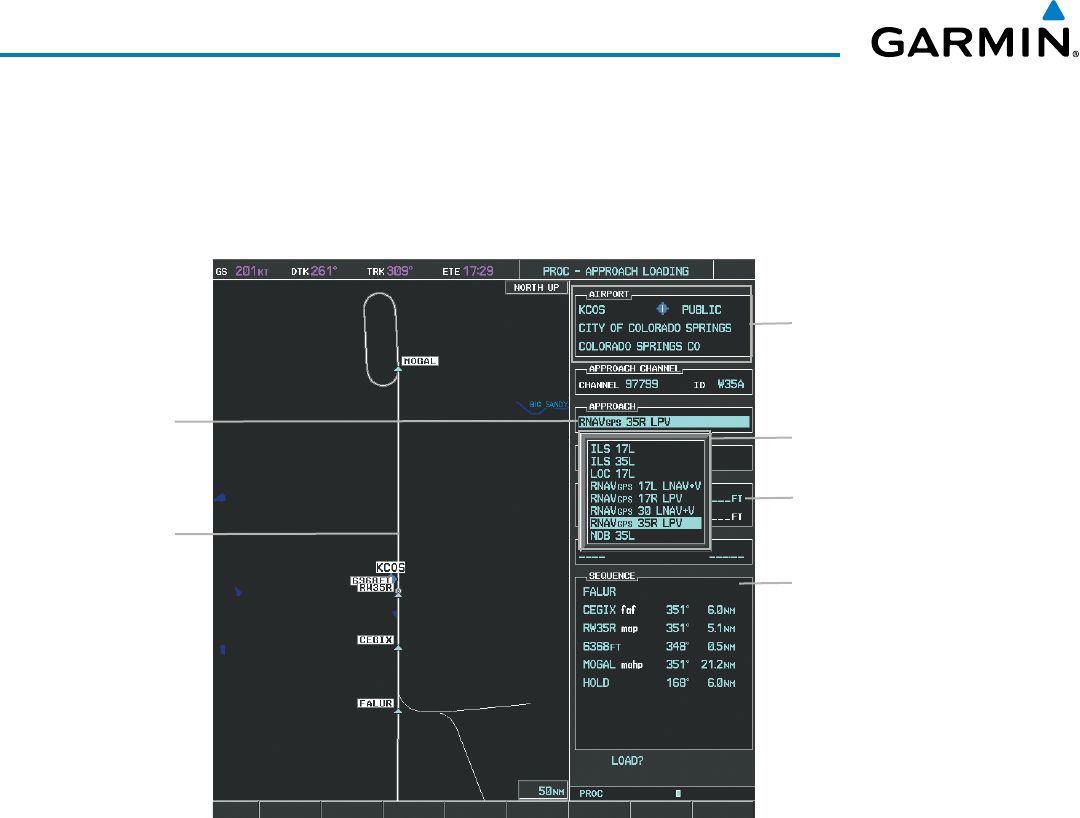
Garmin G1000 Pilot’s Guide for the Beechcraft 200/B200 Series
190-00928-04 Rev. A228
FLIGHT MANAGEMENT
APPROACH (APPR)
An Approach Procedure (APPR) can be loaded at any airport that has an approach available. Only one
approach can be loaded at a time in a flight plan. The route for a selected approach is defined by designating
transition waypoints.
Figure 5-74 Approach Loading Page - Selecting the Approach
Destination Airport
Selected
Approach Approaches Available at
KCOS
Approach Waypoint
Sequence
Preview of
Selected
Approach
Barometric Minimum
Loading an approach procedure into a stored flight plan:
1) Select a stored flight plan from the Flight Plan Catalog Page.
2) Press the EDIT Softkey; or press the MENU Key, select ‘Edit Flight Plan’, and press the ENT Key. The Stored
Flight Plan Page is displayed.
3) Press the LD APR Softkey; or press the MENU Key, select “Load Approach”, and press the ENT Key. The
Approach Loading Page is displayed.
4) Select the airport and approach:
a) Use the FMS Knob to select an airport and press the ENT Key.
b) Select an approach from the list and press the ENT Key.
Or:
a) If necessary, push the FMS Knob to exit the approach list, and use the large FMS Knob to move the cursor to
the APPROACH CHANNEL field.
b) Use the FMS Knob to enter the approach channel number, and press the ENT Key to accept the approach
channel number. The airport and approach are selected.
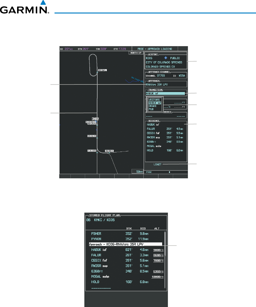
190-00928-04 Rev. A
Garmin G1000 Pilot’s Guide for the Beechcraft 200/B200 Series
229
FLIGHT MANAGEMENT
5) Select a transition for the selected approach. Press the ENT Key.
6) Press the ENT Key to load the selected approach procedure.
Figure 5-75 Approach Loading Page - Selecting the Transition
Destination Airport
Selected
Approach
Transitions Available with
Selected Approach
Approach Waypoint
Sequence
Preview of
Selected
Approach
Load Approach?
Selected Transition
Figure 5-76 Stored Flight Plan Page - Approach Inserted
Inserted Approach Header
- Approach Identifier: [approach
airport].[runway and approach type]
(e.g., KCOS-RNAV 35RGPS LPV)
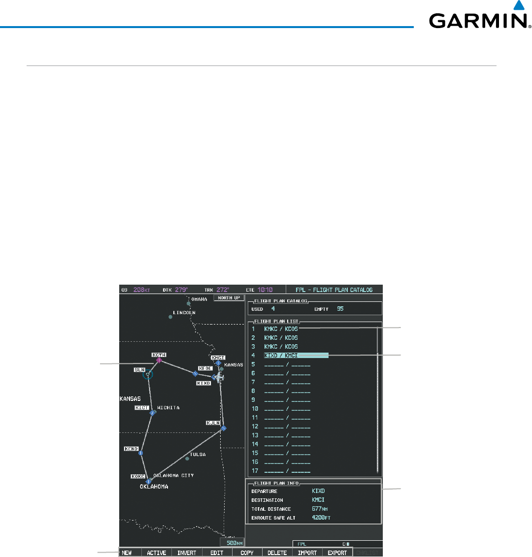
Garmin G1000 Pilot’s Guide for the Beechcraft 200/B200 Series
190-00928-04 Rev. A230
FLIGHT MANAGEMENT
FLIGHT PLAN STORAGE
The G1000 can store up to 99 flight plans, numbered 1 through 99. The active flight plan is erased when
the G1000 is powered off or when another flight plan is activated. Details about each stored flight plan can be
viewed on the Flight Plan Catalog Page and on the Stored Flight Plan Page.
Viewing information about a stored flight plan:
1) Press the FPL Key on the MFD to display the Active Flight Plan Page.
2) Turn the small FMS Knob clockwise one click to display the Flight Plan Catalog Page.
3) Press the FMS Knob to activate the cursor and turn the FMS Knob to highlight the desired flight plan.
4) The Flight Plan Information is displayed showing departure, destination, total distance, and enroute safe altitude
information for the selected Flight Plan.
5) Select the EDIT Softkey to open the Stored Flight Plan Page and view the waypoints in the flight plan.
6) Press the FMS Knob to exit the Stored Flight Plan Page.
Figure 5-77 Stored Flight Plan Information
Preview of Selected
Flight Plan
Stored Flight Plan Info
- Departure Airport
- Destination Airport
- Total Flight Plan Distance
- Enroute Safe Altitude
Flight Plan Name
(Comment)
Selected Flight Plan
Stored FPL Editing
Softkeys
Storing an active flight plan from the Active Flight Plan Page or the Active Flight Plan Window:
1) Press the MENU Key.
2) Highlight ‘Store Flight Plan’.
3) Press the ENT Key.
4) With ‘OK’ highlighted, press the ENT Key. The flight plan is stored in the next available position in the flight
plan list on the Flight Plan Catalog Page.

190-00928-04 Rev. A
Garmin G1000 Pilot’s Guide for the Beechcraft 200/B200 Series
231
FLIGHT MANAGEMENT
ACTIVATE A FLIGHT PLAN
Activating a stored flight plan erases the active flight plan and replaces it with the flight plan being activated.
Inverting a stored flight plan reverses the waypoint order, erases the active flight plan, and replaces it with the
flight plan being activated (the stored flight plan is not changed).
Activating a stored flight plan on the MFD:
1) Press the FPL Key and turn the small FMS Knob to display the Flight Plan Catalog Page.
2) Press the FMS Knob to activate the cursor, and turn the FMS Knob to highlight the desired flight plan.
3) Select the ACTIVE Softkey; or press the ENT Key twice; or press the MENU Key, highlight ‘Activate Flight Plan’,
and press the ENT Key. The ‘Activate Stored Flight Plan?’ window is displayed.
4) With ‘OK’ highlighted, press the ENT Key. To cancel the request, press the CLR Key, or highlight ‘CANCEL’ and
press the ENT Key.
Inverting and activating a stored flight plan on the MFD:
1) Press the FPL Key and turn the small FMS Knob to display the Flight Plan Catalog Page.
2) Press the FMS Knob to activate the cursor, and turn the FMS Knob to highlight the desired flight plan.
3) Select the INVERT Softkey; or press the MENU Key, highlight ‘Invert & Activate FPL?’, and press the ENT Key.
The ‘Invert and activate stored flight plan?’ window is displayed.
4) With ‘OK’ highlighted, press the ENT Key. To cancel the request, press the CLR Key, or highlight ‘CANCEL’ and
press the ENT Key.
COPY A FLIGHT PLAN
The G1000 allows copying a flight plan into a new flight plan memory slot, allowing editing, etc., without
affecting the original flight plan. This can be used to duplicate an existing stored flight plan for use in creating
a modified version of the original stored flight plan.
Copying a stored flight plan on the MFD:
1) Press the FPL Key and turn the small FMS Knob to display the Flight Plan Catalog Page.
2) Press the FMS Knob to activate the cursor, and turn the FMS Knob to highlight the desired flight plan.
3) Select the COPY Softkey; or press the MENU Key, highlight ‘Copy Flight Plan’, and press the ENT Key. The
‘Copy to Flight Plan XX?’ window is displayed.
4) With ‘OK’ highlighted, press the ENT Key to copy the flight plan. To cancel the request, press the CLR Key, or
highlight ‘CANCEL’ and press the ENT Key.
DELETE A STORED FLIGHT PLAN
Individual or all stored flight plans can be deleted from the G1000 memory.
Deleting a stored flight plan:
1) Press the FPL Key and turn the small FMS Knob to display the Flight Plan Catalog Page.
2) Press the FMS Knob to activate the cursor, and turn the FMS Knob to highlight the desired flight plan.
Garmin G1000 Pilot’s Guide for the Beechcraft 200/B200 Series
190-00928-04 Rev. A232
FLIGHT MANAGEMENT
3) Select the DELETE Softkey; press the CLR Key; or press the MENU Key, highlight ‘Delete Flight Plan’, and press
the ENT Key. The ‘Delete Flight Plan XX?’ window is displayed.
4) With ‘OK’ highlighted, press the ENT Key to delete the flight plan. To cancel the request, press the CLR Key, or
highlight ‘CANCEL’ and press the ENT Key.
NOTE: The option to delete all stored flight plans is not available while the aircraft is in flight.
Deleting all stored flight plans:
1) Press the FPL Key and turn the small FMS Knob to display the Flight Plan Catalog Page.
2) Press the MENU Key.
3) Highlight ‘Delete All’ and press the ENT Key. A ‘Delete all flight plans?’ confirmation window is displayed.
4) With ‘OK’ highlighted, press the ENT Key to delete all flight plans. To cancel the request, press the CLR Key, or
highlight ‘CANCEL’ and press the ENT Key.
FLIGHT PLAN EDITING
The active flight plan or any stored flight plan can be edited. The edits made to the active flight plan affect
navigation as soon as they are entered.
DELETING THE ACTIVE FLIGHT PLAN
The G1000 allows deleting an active flight plan. Deleting the active flight plan suspends navigation by the
G1000.
Deleting the active flight plan:
1) Press the FPL Key to display the Active Flight Plan Page (MFD) or the Active Flight Plan Window (PFD).
2) Press the MENU Key, highlight ‘Delete Flight Plan’, and press the ENT Key. The ‘Delete all waypoints in flight
plan?’ window is displayed.
3) With ‘OK’ highlighted, press the ENT Key to delete the active flight plan. To cancel the request, press the CLR
Key, or highlight ‘CANCEL’ and press the ENT Key.
DELETING FLIGHT PLAN ITEMS
Individual waypoints, entire airways, and entire procedures can be deleted from a flight plan. Some waypoints
in the final approach segment (such as the FAF or MAP) can not be deleted individually. Attempting to delete
a waypoint that is not allowed results in a window displaying ‘Invalid flight plan modification.’
Deleting an individual waypoint from the active flight plan:
1) Press the FPL Key to display the Active Flight Plan Page (MFD) or the Active Flight Plan Window (PFD).
2) Press the FMS Knob to activate the cursor (not required on the PFD) and turn the large FMS Knob to highlight
the waypoint to be deleted.
3) Press the CLR Key. The ‘Remove XXXXX?’ window is displayed.

190-00928-04 Rev. A
Garmin G1000 Pilot’s Guide for the Beechcraft 200/B200 Series
233
FLIGHT MANAGEMENT
4) With ‘OK’ highlighted, press the ENT Key. To cancel the request, press the CLR Key, or highlight ‘CANCEL’ and
press the ENT Key.
5) Press the FMS Knob to remove the flashing cursor.
Deleting an entire airway from the active flight plan:
1) Press the FPL Key to display the Active Flight Plan Page (MFD) or the Active Flight Plan Window (PFD).
2) Press the FMS Knob to activate the cursor (not required on the PFD) and turn the large FMS Knob to highlight
the white header of the airway to be deleted.
3) Press the CLR Key. The ‘Remove <airway name>?’ window is displayed.
4) With ‘OK’ highlighted, press the ENT Key. To cancel the request, press the CLR Key, or highlight ‘CANCEL’ and
press the ENT Key.
5) Press the FMS Knob to remove the flashing cursor.
Deleting an entire procedure from the active flight plan:
1) Press the FPL Key to display the Active Flight Plan Page (MFD) or the Active Flight Plan Window (PFD).
2) Press the FMS Knob to activate the cursor (not required on the PFD) and turn the large FMS Knob to highlight
the white header of the procedure to be deleted.
3) Press the CLR Key. The ‘Remove <procedure name> from flight plan?’ window is displayed.
4) With ‘OK’ highlighted, press the ENT Key. To cancel the request, press the CLR Key, or highlight ‘CANCEL’ and
press the ENT Key.
5) Press the FMS Knob to remove the flashing cursor.
Or:
1) Press the FPL Key to display the Active Flight Plan Page (MFD) or the Active Flight Plan Window (PFD).
2) Press the MENU Key to display the Page Menu and turn the FMS Knob to highlight ‘Remove <procedure>’.
3) Press the ENT Key. The ‘Remove <procedure name> from flight plan?’ window is displayed.
4) With ‘OK’ highlighted, press the ENT Key. To cancel the request, press the CLR Key, or highlight ‘CANCEL’ and
press the ENT Key.
Deleting an individual waypoint from a stored flight plan:
1) Press the FPL Key to display the Active Flight Plan Page.
2) Turn the small FMS Knob clockwise one click to display the Flight Plan Catalog Page.
3) Press the FMS Knob to activate the cursor and turn the FMS Knob to highlight the flight plan to be edited.
4) Select the EDIT Softkey; or press the MENU Key, select ‘Edit Flight Plan’ and press the ENT Key. The Stored
Flight Plan Page is displayed.
5) Turn the large FMS Knob to highlight the waypoint to be deleted.
6) Press the CLR Key. The ‘Remove XXXXX?’ window is displayed.

Garmin G1000 Pilot’s Guide for the Beechcraft 200/B200 Series
190-00928-04 Rev. A234
FLIGHT MANAGEMENT
7) With ‘OK’ highlighted, press the ENT Key. To cancel the request, press the CLR Key, or highlight ‘CANCEL’ and
press the ENT Key.
8) Press the FMS Knob to remove the flashing cursor.
Deleting an entire airway from a stored flight plan:
1) Press the FPL Key to display the Active Flight Plan Page.
2) Turn the small FMS Knob clockwise one click to display the Flight Plan Catalog Page.
3) Press the FMS Knob to activate the cursor and turn the FMS Knob to highlight the flight plan to be edited.
4) Select the EDIT Softkey; or press the MENU Key, select ‘Edit Flight Plan’ and press the ENT Key. The Stored
Flight Plan Page is displayed.
5) Turn the large FMS Knob to highlight the white header of the airway to be deleted.
6) Press the CLR Key. The ‘Remove <airway name>?’ window is displayed.
7) With ‘OK’ highlighted, press the ENT Key. To cancel the request, press the CLR Key, or highlight ‘CANCEL’ and
press the ENT Key.
8) Press the FMS Knob to remove the flashing cursor.
Deleting an entire procedure from a stored flight plan:
1) Press the FPL Key to display the Active Flight Plan Page.
2) Turn the small FMS Knob clockwise one click to display the Flight Plan Catalog Page.
3) Press the FMS Knob to activate the cursor and turn the FMS Knob to highlight the flight plan to be edited.
4) Select the EDIT Softkey; or press the MENU Key, select ‘Edit Flight Plan’ and press the ENT Key. The Stored
Flight Plan Page is displayed.
5) Turn the large FMS Knob to highlight the white header of the procedure to be deleted.
6) Press the CLR Key. The ‘Remove <procedure name> from flight plan?’ window is displayed.
7) With ‘OK’ highlighted, press the ENT Key. To cancel the request, press the CLR Key, or highlight ‘CANCEL’ and
press the ENT Key.
8) Press the FMS Knob to remove the flashing cursor.
Or:
1) Press the FPL Key to display the Active Flight Plan Page.
2) Turn the small FMS Knob clockwise one click to display the Flight Plan Catalog Page.
3) Press the FMS Knob to activate the cursor and turn the FMS Knob to highlight the flight plan to be edited.
4) Select the EDIT Softkey; or press the MENU Key, select ‘Edit Flight Plan’ and press the ENT Key. The Stored
Flight Plan Page is displayed.
5) Press the MENU Key to display the Page Menu and turn the FMS Knob to highlight ‘Remove <procedure>’.
6) Press the ENT Key. The ‘Remove <procedure name> from flight plan?’ window is displayed.

190-00928-04 Rev. A
Garmin G1000 Pilot’s Guide for the Beechcraft 200/B200 Series
235
FLIGHT MANAGEMENT
7) With ‘OK’ highlighted, press the ENT Key. To cancel the request, press the CLR Key, or highlight ‘CANCEL’ and
press the ENT Key.
8) Press the FMS Knob to remove the flashing cursor.
CHANGING FLIGHT PLAN COMMENTS (NAMES)
The comment field (or name) of each flight plan can be changed to something that is useful for identification
and sorting.
Changing the active flight plan comment:
1) Press the FPL Key to display the Active Flight Plan Page.
2) Press the FMS Knob to activate the cursor and turn the large FMS Knob to highlight the comment field.
3) Use the FMS Knobs to edit the comment.
4) Press the ENT Key to accept the changes.
5) Press the FMS Knob to remove the flashing cursor.
Changing a stored flight plan comment:
1) Press the FPL Key to display the Active Flight Plan Page.
2) Turn the small FMS Knob clockwise one click to display the Flight Plan Catalog Page.
3) Press the FMS Knob to activate the cursor and turn the FMS Knob to highlight the flight plan to be edited.
4) Select the EDIT Softkey; or press the MENU Key, select ‘Edit Flight Plan’ and press the ENT Key. The Stored
Flight Plan Page is displayed.
5) Turn the large FMS Knob to highlight the comment field.
6) Use the FMS Knobs to edit the comment.
7) Press the ENT Key to accept the changes.
8) Press the FMS Knob to remove the flashing cursor.
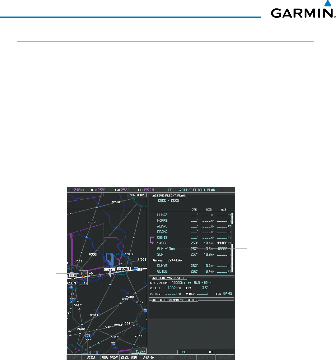
Garmin G1000 Pilot’s Guide for the Beechcraft 200/B200 Series
190-00928-04 Rev. A236
FLIGHT MANAGEMENT
ALONG TRACK OFFSETS
A waypoint having an “along track offset” distance from an existing waypoint can be entered into a flight plan.
Along track offset waypoints lie along the path of the existing flight plan, and can be used to make the system
reach a specified altitude before or after reaching the specified flight plan waypoint. Offset distances can be
entered from 1 to 999 nm in increments of 1 nm. Entering a negative offset distance results in an along track
offset waypoint inserted before the selected waypoint, whereas entering a positive offset distance results in an
along track offset waypoint inserted after the selected waypoint. Multiple offset waypoints are allowed.
A waypoint must be adjacent to its parent waypoint in the flight plan, so the system limits the along-track
distance to less than the length of the leg before or after the selected waypoint. If the selected waypoint is the
active waypoint, the distance is limited to less than the distance to go to the active waypoint. Assigning an along
track offset to a leg with indeterminate length is not permitted. An along track offset is not allowed at or after
the final approach fix of an approach.
An along track offset distance cannot be modified once entered. If the along track offset distance must be
changed, the existing along track offset waypoint must be deleted and a new one created with the new offset
distance.
Figure 5-78 Along Track Offset
Along Track
Offset Waypoint
and Distance
Along Track Offset
Waypoint and Distance
from Flight Plan Waypoint
Entering an along track offset distance:
1) Press the FPL Key to display the Active Flight Plan Page (MFD) or the Active Flight Plan Window (PFD).
2) Press the FMS Knob to activate the cursor (not required on the PFD) and turn the large FMS Knob to highlight
the waypoint for the along track offset.
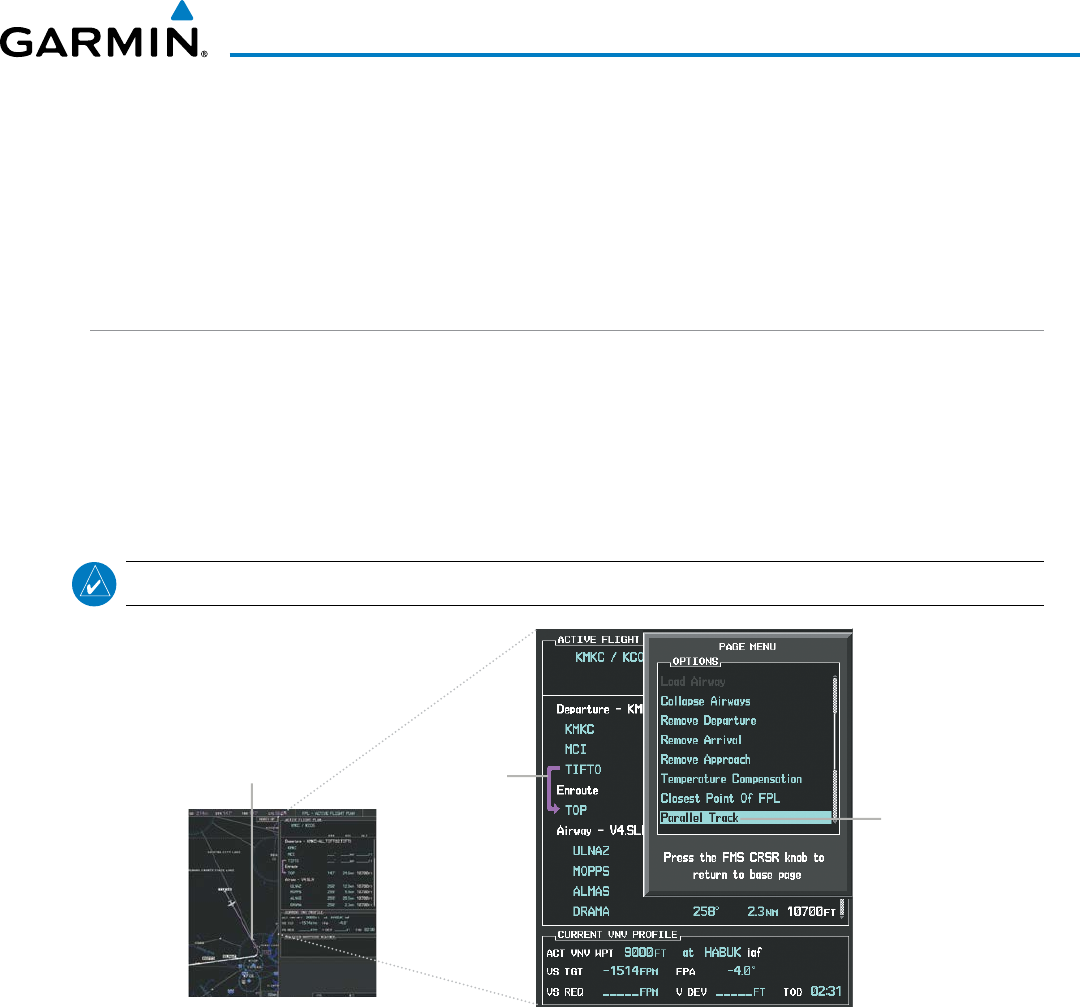
190-00928-04 Rev. A
Garmin G1000 Pilot’s Guide for the Beechcraft 200/B200 Series
237
FLIGHT MANAGEMENT
3) Select the ATK OFST Softkey (MFD only); or press the MENU Key, highlight ‘Create ATK Offset Waypoint’, and
press the ENT Key.
4) Enter a positive or negative offset distance in the range of +/- 1 to 999 nm (limited by leg distances).
5) Press the ENT Key to create the offset waypoint.
6) Press the FMS Knob to remove the flashing cursor.
PARALLEL TRACK
The Parallel Track (PTK) feature allows creation of a parallel course offset of 1 to 50 nm left or right of the
current flight plan. When Parallel Track is activated, the course line drawn on the map pages shows the parallel
course, and waypoint names have a lower case “p” placed after the identifier.
Using direct-to, loading an approach, a holding pattern, or editing and activating the flight plan automatically
cancels Parallel Track. Parallel Track is also cancelled if a course change occurs greater than 120° or the parallel
tracks overlap as a result of the course change.
NOTE: Vertical navigation is unavailable while the Parallel Track feature is active.
Figure 5-79 Active Flight Plan Window - Selecting Parallel Track
Selecting Parallel
Track
Active Flight Plan prior to Parallel Track
Activating parallel track:
1) Press the FPL Key to display the Active Flight Plan Page (MFD) or the Active Flight Plan Window (PFD).
2) Press the MENU Key, highlight ‘Parallel Track’, and press the ENT Key. The Parallel Track Window is displayed
with the direction field highlighted.
3) Turn the small FMS Knob to select ‘Left’ or ‘Right’ and press the ENT Key. The ‘DISTANCE’ field is highlighted.
4) Turn the small FMS Knob to enter a distance from 1-99 nm and press the ENT Key. ‘ACTIVATE PARALLEL
TRACK’ is highlighted.
5) Press the ENT Key to activate parallel track. Press the FMS Knob or the CLR Key to cancel the parallel track
activation.
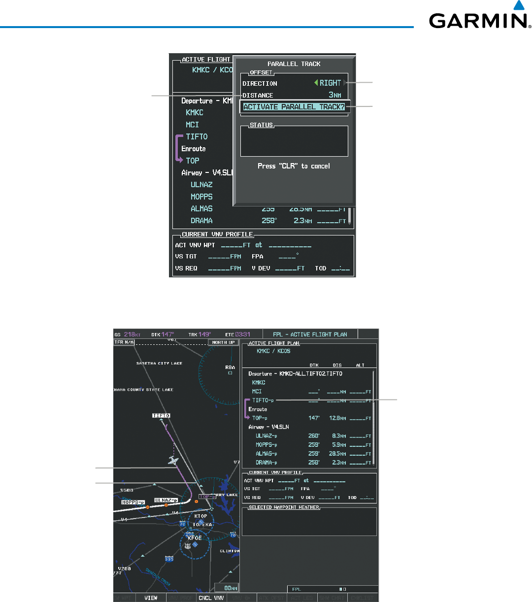
Garmin G1000 Pilot’s Guide for the Beechcraft 200/B200 Series
190-00928-04 Rev. A238
FLIGHT MANAGEMENT
Figure 5-80 Parallel Track Window
Offset Direction
Offset Distance
Activation Prompt
Figure 5-81 Parallel Track Active
Parallel Track Waypoints
- TIFTO-p
- TOP-p
- ...
- LAA-p
Activating Parallel Track
affects the active flight plan
from the current position on
(will not affect an approach)
Parallel Track
Original Track
If the parallel track proposed by the offset direction and distance is not allowed by the system, the activation
prompt is displayed, but disabled. Parallel Track cannot be activated if a course is set using direct-to or if the
active leg is the first leg of the departure procedure. Attempting to activate parallel track with these conditions
results in the message ‘Parallel Track Unavailable Invalid Route Geometry’. If an approach leg is active the status
indicates that the system is unable to activate the parallel track with the message ‘Parallel Track Unavailable
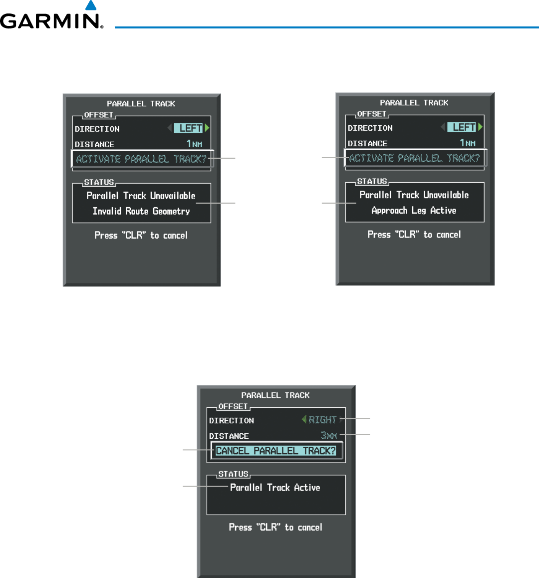
190-00928-04 Rev. A
Garmin G1000 Pilot’s Guide for the Beechcraft 200/B200 Series
239
FLIGHT MANAGEMENT
Approach Leg Active’. If the offset direction and distance results in an unreasonable route geometry the status
indicates that the system is unable to activate the parallel track because of invalid geometry.
Figure 5-82 Parallel Track Unavailable
Subdued Prompt
(Unavailable)
Unavailable Status
Invalid Approach
Geometry Active
If the active leg is not a track between two fixes (TF) or a course to a fix (DF) leg, the status
indicates that the system is unable to activate the parallel track because parallel track is not available for the
active leg type.
Figure 5-83 Cancelling Parallel Track
Cancel Prompt
Active Status
Offset Direction &
Distance Subdued
(Unavailable)
Cancelling parallel track:
1) Press the FPL Key to display the Active Flight Plan Page (MFD) or the Active Flight Plan Window (PFD).
2) Press the MENU Key, highlight ‘Parallel Track’, and press the ENT Key. The Parallel Track Window is displayed
with ‘CANCEL PARALLEL TRACK?’ highlighted.
3) Press the ENT Key.
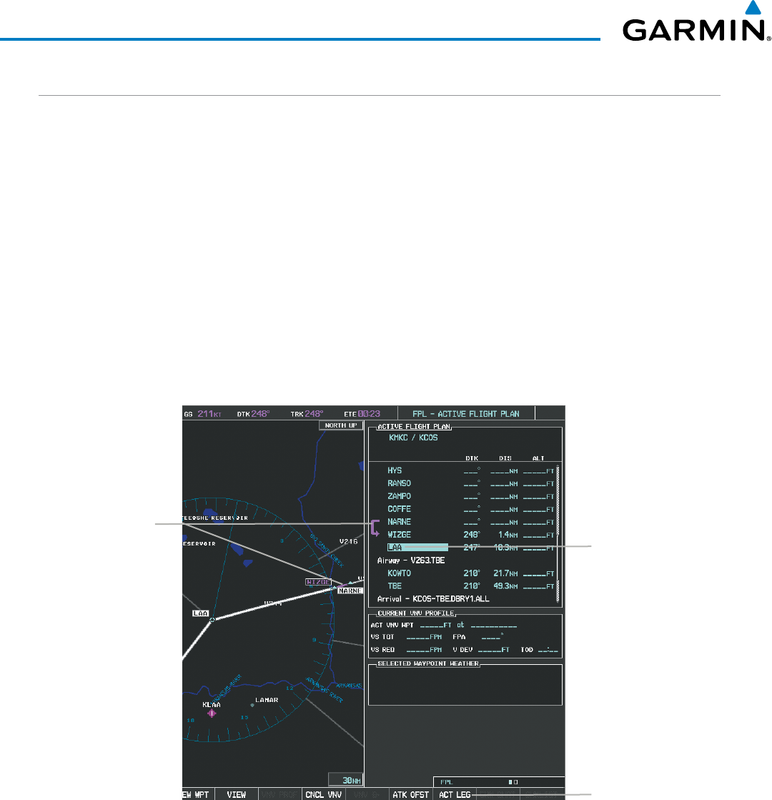
Garmin G1000 Pilot’s Guide for the Beechcraft 200/B200 Series
190-00928-04 Rev. A240
FLIGHT MANAGEMENT
ACTIVATING A FLIGHT PLAN LEG
The G1000 allows selection of a highlighted leg as the “active leg” (the flight plan leg which is currently
used for navigation guidance).
Activating a flight plan leg:
1) Press the FPL Key to display the Active Flight Plan Page (MFD) or the Active Flight Plan Window (PFD).
2) Press the FMS Knob to activate the cursor (not required on the PFD) and turn the large FMS Knob to highlight
the destination waypoint for the desired leg.
3) Select the ACT LEG Softkey (MFD only); or press the MENU Key, highlight ‘Activate Leg’, and press the ENT Key.
A confirmation window is displayed with ‘ACTIVATE’ highlighted.
4) Press the ENT Key to activate the flight plan leg. To cancel, press the CLR Key, or highlight ‘CANCEL’ and press
the ENT Key.
5) Press the FMS Knob to remove the flashing cursor.
Figure 5-84 Active Flight Plan Page - Selecting the Leg Destination Waypoint
Current
Active Leg
Activate Leg Softkey
Selected Destination
Waypoint
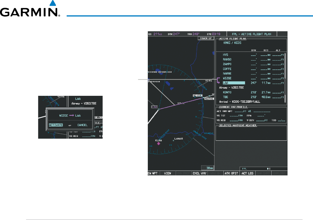
190-00928-04 Rev. A
Garmin G1000 Pilot’s Guide for the Beechcraft 200/B200 Series
241
FLIGHT MANAGEMENT
Figure 5-85 Active Flight Plan Page - New Active Leg
New Active
Flight Plan Leg
Confirmation Window
INVERTING A FLIGHT PLAN
Any flight plan may be inverted (reversed) for navigation back to the original departure point.
Inverting the active flight plan:
1) Press the FPL Key to display the Active Flight Plan Page (MFD) or the Active Flight Plan Window (PFD).
2) Press the MENU Key, highlight ‘Invert Flight Plan’, and press the ENT Key. An ‘Invert Active Flight Plan?’
confirmation window is displayed.
3) Select ‘OK’.
4) Press the ENT Key to invert and activate the active flight plan. To cancel, press the CLR Key, or highlight
‘CANCEL’ and press the ENT Key.
Inverting and activating a stored flight plan:
1) Press the FPL Key and turn the small FMS Knob to display the Flight Plan Catalog Page.
2) Press the FMS Knob to activate the cursor, and turn the FMS Knob to highlight the desired flight plan.
3) Select the INVERT Softkey; or press the MENU Key, highlight ‘Invert & Activate FPL?’, and press the ENT Key.
The ‘Invert and activate stored flight plan?’ window is displayed.
4) With ‘OK’ highlighted, press the ENT Key. To cancel the request, press the CLR Key, or highlight ‘CANCEL’ and
press the ENT Key.
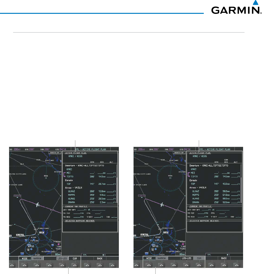
Garmin G1000 Pilot’s Guide for the Beechcraft 200/B200 Series
190-00928-04 Rev. A242
FLIGHT MANAGEMENT
FLIGHT PLAN VIEWS
Information about flight plans can be viewed in more than one way. The active flight plan can be configured
to show cumulative distance over the length of the flight plan or the distance for each leg of the flight plan;
and the active flight plan can be viewed in a narrow or wide view. In the wide view, additional information is
displayed: Fuel Remaining (FUEL REM), Estimated Time Enroute (ETE), Estimated Time of Arrival (ETA), and
Bearing to the waypoint (BRG).
Switching between leg-to-leg waypoint distance and cumulative waypoint distance:
1) Press the FPL Key on the MFD to display the Active Flight Plan Page.
2) Select the VIEW Softkey to display the CUM and LEG-LEG Softkeys.
3) Select the CUM Softkey to view cumulative waypoint distance, or select the LEG-LEG Softkey to view leg-to-leg
waypoint distance.
4) Select the BACK Softkey to return to the top level active flight plan softkeys.
Figure 5-86 Active Flight Plan - Leg to Leg vs. Cumulative Distance
Active Flight Plan
Leg to Leg Distance
Active Flight Plan
Cumulative Distance
WIDE Softkey, NARROW Softkey, LEG-LEG Softkey, CUM Softkey
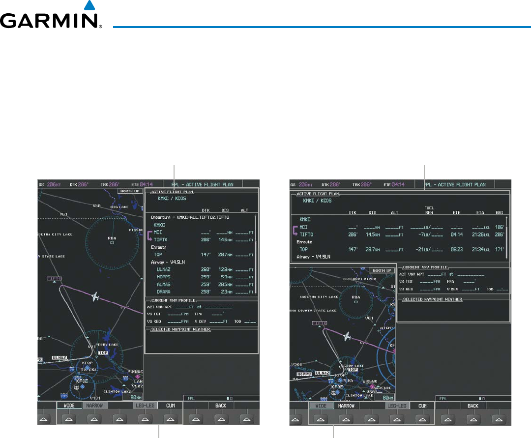
190-00928-04 Rev. A
Garmin G1000 Pilot’s Guide for the Beechcraft 200/B200 Series
243
FLIGHT MANAGEMENT
Switching between wide and narrow view:
1) Press the FPL Key on the MFD to display the Active Flight Plan Page.
2) Select the VIEW Softkey to display the WIDE and NARROW Softkeys.
3) Select the WIDE Softkey to display the wide view, or select the NARROW Softkey to display the narrow view.
4) Select the BACK Softkey to return to the top level active flight plan softkeys.
Figure 5-87 Active Flight Plan - Wide vs. Narrow View
WIDE Softkey, NARROW Softkey, LEG-LEG Softkey, CUM Softkey
Active Flight Plan
Narrow View
Active Flight Plan
Wide View
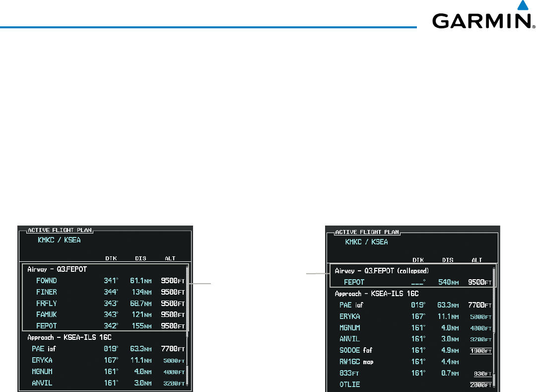
Garmin G1000 Pilot’s Guide for the Beechcraft 200/B200 Series
190-00928-04 Rev. A244
FLIGHT MANAGEMENT
COLLAPSING AIRWAYS
The G1000 allows airways on the active flight plan to be collapsed or expanded from the Active Flight Plan
Page/Window. When airways have been collapsed, it is indicated on the airway heading.
When airways are collapsed, leg-to-leg computed values such as DIS or ETE shown for the exit waypoint
reflect the total of all the legs on the airway that have been hidden in the collapsed display. The DTK value is
inhibited because it is not usable in this context.
The Active Flight Plan Page always keeps the following three waypoints visible: “From” waypoint, “To”
waypoint, and “Next” waypoint. To prevent one or more of these waypoints from being hidden in a collapsed
airway segment, the airway segment that contains either the “To” or the “Next” waypoint is automatically
expanded. When an airway is loaded, airways are automatically expanded to facilitate flight plan review.
Figure 5-88 Expanded/Collapsed Airways
Q3.FEPOT Airway
Collapsed View
Expanded View
Collapsing/expanding the airways in the active flight plan:
1) Press the FPL Key to display the Active Flight Plan Page (MFD) or the Active Flight Plan Window (PFD).
2) Press the MENU Key, highlight ‘Collapse Airways’ or ‘Expand Airways’, and press the ENT Key. The airways are
collapsed/expanded.

190-00928-04 Rev. A
Garmin G1000 Pilot’s Guide for the Beechcraft 200/B200 Series
245
FLIGHT MANAGEMENT
CLOSEST POINT OF FPL
‘Closest Point of FPL’ calculates the bearing and closest distance at which a flight plan passes a reference
waypoint, and creates a new user waypoint along the flight plan at the location closest to a chosen reference
waypoint.
Determining the closest point along the active flight plan to a selected waypoint:
1) Press the FPL Key to display the Active Flight Plan Page (MFD) or the Active Flight Plan Window (PFD).
2) Press the MENU Key, highlight ‘Closest Point Of FPL’’, and press the ENT Key. A window appears with the
reference waypoint field highlighted.
3) Enter the identifier of the reference waypoint and press the ENT Key. The G1000 displays the bearing (BRG) and
distance (DIS) to the closest point along the flight plan to the selected reference waypoint and creates a user
waypoint at this location. The name for the new user waypoint is derived from the identifier of the reference
waypoint.
USER-DEFINED HOLDING PATTERNS
A holding pattern can be defined at any active flight plan waypoint, at the aircraft present position, or at a
direct-to waypoint.
Creating a user-defined hold at an active flight plan waypoint:
1) Press the FPL Key to display the Active Flight Plan Page (MFD) or the Active Flight Plan Window (PFD).
2) Press the FMS Knob to activate the cursor (not required on the PFD) and turn the large FMS Knob to highlight
the waypoint for the hold.
3) Press the MENU Key, highlight ‘Hold At Waypoint’, and press the ENT Key. The HOLD AT window appears with
the course field highlighted.
4) Use the FMS Knobs to edit the entry course, and press the ENT Key.
5) Use the small FMS Knob to select ‘INBOUND’ or ‘OUTBOUND’ course direction, and press the ENT Key.
6) Use the small FMS Knob to select ‘TIME’ or ‘DIST’ length mode, and press the ENT Key.
7) Use the FMS Knobs to edit the length, and press the ENT Key.
8) Use the small FMS Knob to select ‘RIGHT’ or ‘LEFT’ turn direction, and press the ENT Key.
9) Use the FMS Knobs to edit the Expect Further Clearance Time (EFC TIME), and press the ENT Key.
10) Press the ENT Key while ‘LOAD?’ is highlighted to insert the hold into the flight plan.
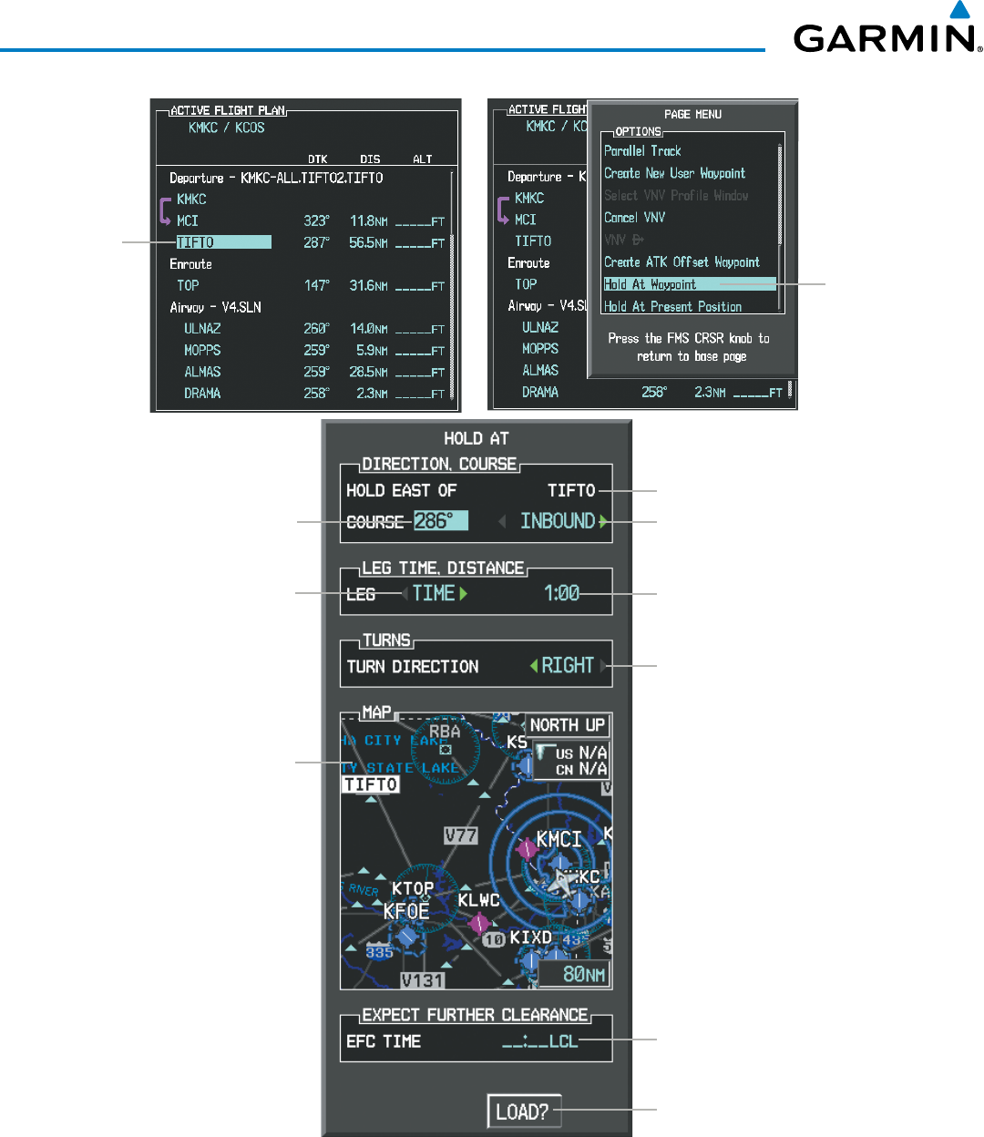
Garmin G1000 Pilot’s Guide for the Beechcraft 200/B200 Series
190-00928-04 Rev. A246
FLIGHT MANAGEMENT
Waypoint
Selected
Hold At
Wpt Menu
Selection
Figure 5-89 Creating a User Defined Holding Pattern at an Active Flight Plan Waypoint
Location of Hold
Expect Further Clearance Time
Leg Length Mode Button
(TIME or DIST))
Map of Hold Location
Course Direction
(INBOUND or OUTBOUND)
Leg Length
(Time in nm or Distance in minutes)
Hold Entry Course
Turn Direction
(RIGHT or LEFT)
Load Hold in Active Flight Plan

190-00928-04 Rev. A
Garmin G1000 Pilot’s Guide for the Beechcraft 200/B200 Series
247
FLIGHT MANAGEMENT
Creating a user-defined hold at the aircraft present position:
1) Press the FPL Key to display the Active Flight Plan Page (MFD) or the Active Flight Plan Window (PFD).
2) Press the MENU Key, highlight ‘Hold At Present Position’, and press the ENT Key. The HOLD AT window appears
with the course field highlighted.
3) If desired, use the FMS Knobs to entry the entry course, and press the ENT Key.
4) Use the small FMS Knob to select ‘INBOUND’ or ‘OUTBOUND’ course direction, and press the ENT Key.
5) Use the small FMS Knob to select ‘TIME’ or ‘DIST’ length mode, and press the ENT Key.
6) Use the FMS Knobs to edit the length, and press the ENT Key.
7) Use the small FMS Knob to select ‘RIGHT’ or ‘LEFT’ turn direction, and press the ENT Key.
8) Use the FMS Knobs to edit the Expect Further Clearance Time (EFC TIME), and press the ENT Key.
9) Press the ENT Key while ‘ACTIVATE?’ is highlighted to create an Offroute Direct-to hold waypoint and activate
the hold.
Creating a user-defined hold at a direct-to waypoint:
1) Press a Direct-to Key and set up the direct-to waypoint as desired, but select ‘HOLD?’ instead of ‘ACTIVATE?’
when finished (MFD or PFD).
2) Use the FMS Knobs to edit the entry course, and press the ENT Key.
3) Use the small FMS Knob to select ‘INBOUND’ or ‘OUTBOUND’ course direction, and press the ENT Key.
4) Use the small FMS Knob to select ‘TIME’ or ‘DIST’ length mode, and press the ENT Key.
5) Use the FMS Knobs to edit the length, and press the ENT Key.
6) Use the small FMS Knob to select ‘RIGHT’ or ‘LEFT’ turn direction, and press the ENT Key.
7) Use the FMS Knobs to edit the Expect Further Clearance Time (EFC TIME), and press the ENT Key.
8) Press the ENT Key while ‘ACTIVATE?’ is highlighted to activate the direct-to with the user-defined hold defined
at the direct-to waypoint. (If the direct-to wayoint is part of the active flight plan, the HOLD is inserted into
the active flight plan. If the direct-to waypoint is not part of the active flight plan, an off-route direct-to hold is
created.)
Exiting a user-defined hold inserted into the active flight plan:
Press the SUSP Softkey. The system will provide guidance to follow the holding pattern to the inbound course
and resume automatic waypoint sequencing.
Removing a user-defined hold inserted into the active flight plan:
1) Press the FPL Key to display the Active Flight Plan Page (MFD) or the Active Flight Plan Window (PFD).
2) Press the FMS Knob to activate the cursor (not required on the PFD) and turn the large FMS Knob to highlight
the HOLD waypoint.
3) Press the CLR Key. A ‘Remove Holding Pattern?’ confirmation window is displayed.
4) Select ‘OK’ and press the ENT Key. The holding pattern is removed from the active flight plan. Select ‘CANCEL’
and press the ENT Key to cancel the removal of the holding pattern.
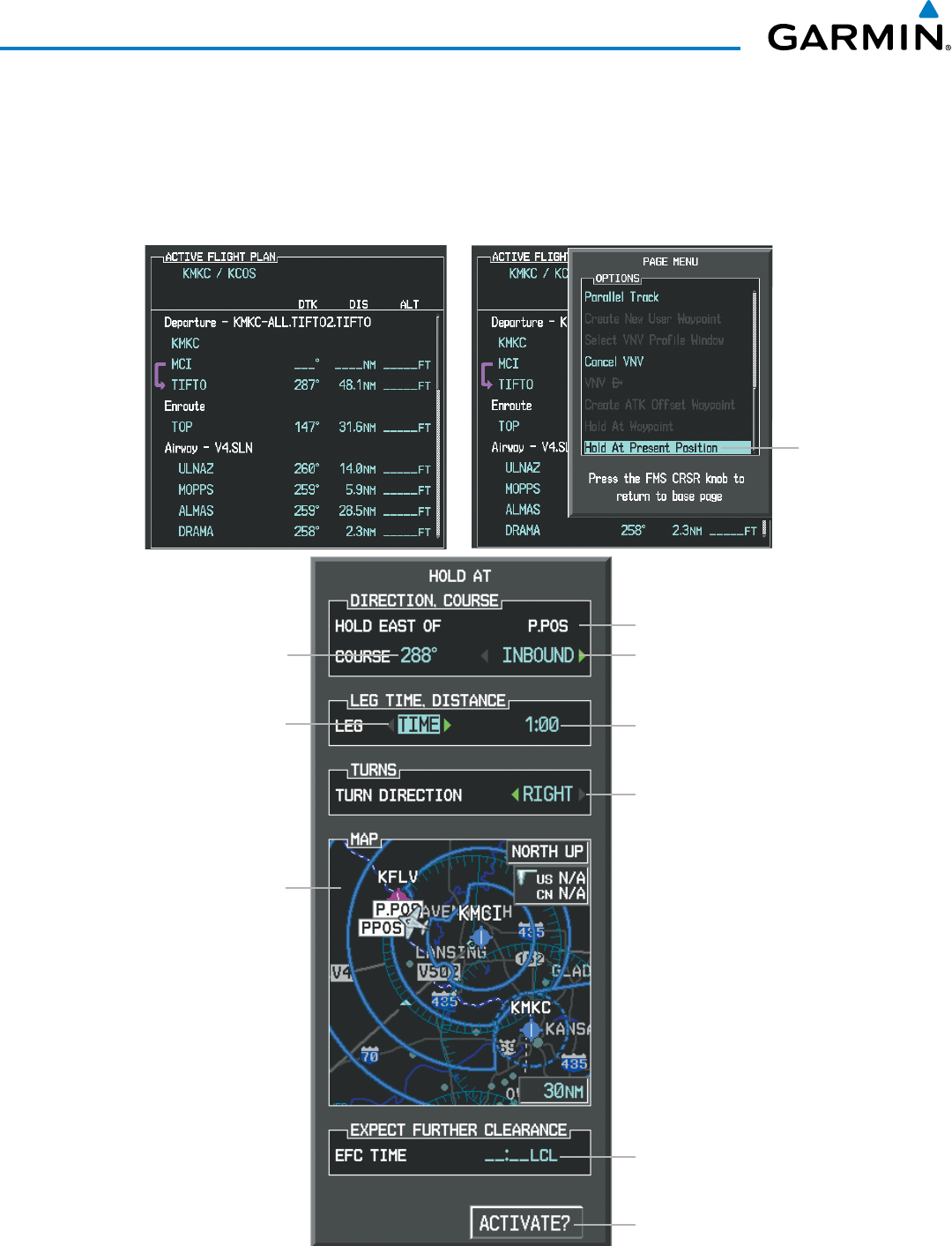
Garmin G1000 Pilot’s Guide for the Beechcraft 200/B200 Series
190-00928-04 Rev. A248
FLIGHT MANAGEMENT
Removing a user-defined hold at an off-route direct-to:
1) Press a Direct To Key to display the DIRECT TO Window (PFD or MFD).
2) Press the MENU Key to display the PAGE MENU with the cursor on the ‘Cancel Direct-To NAV’ selection.
3) Press the ENT Key. The holding pattern is removed.
Hold At
Present
Position
Menu
Selection
Figure 5-90 Creating a User Defined Holding Pattern at the Aircraft Present Position
Location of Hold
Expect Further Clearance Time
Leg Length Mode Button
(TIME or DIST))
Map of Hold Location
Course Direction
(INBOUND or OUTBOUND)
Leg Length
(Time in nm or Distance in minutes)
Hold Entry Course
Turn Direction
(RIGHT or LEFT)
Activate Hold
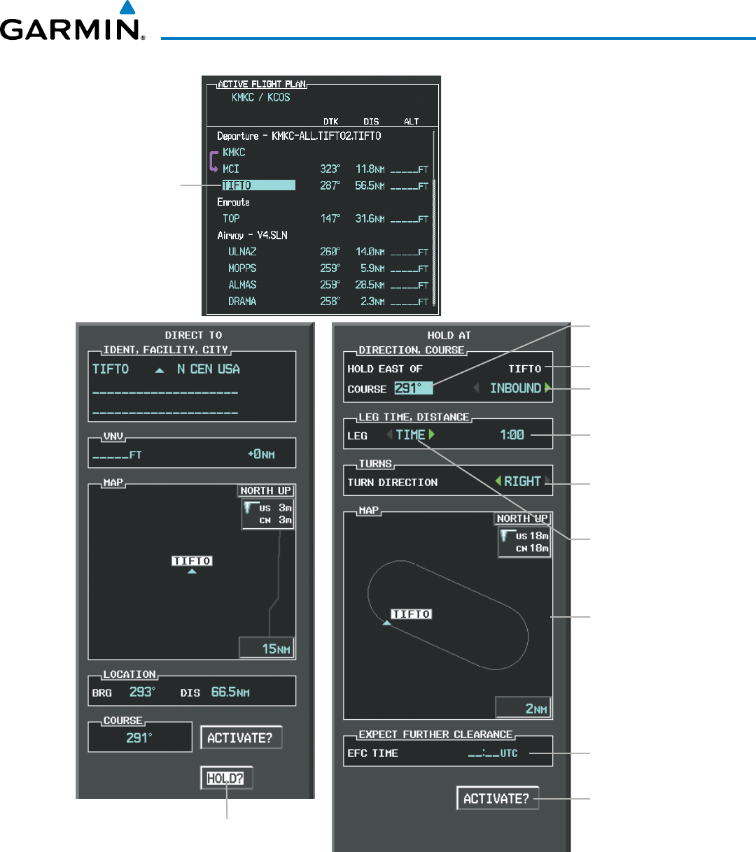
190-00928-04 Rev. A
Garmin G1000 Pilot’s Guide for the Beechcraft 200/B200 Series
249
FLIGHT MANAGEMENT
Waypoint
Selected
Hold At Direct To
Waypoint selection
Figure 5-91 Creating a User Defined Holding Pattern at a Direct To Waypoint
Location of Hold
Expect Further
Clearance Time
Course Direction
(INBOUND or OUTBOUND)
Leg Length
(Time in nm or
Distance in minutes)
Turn Direction
(RIGHT or LEFT)
Load Hold and
Activate Direct To
Map of Hold Location
Hold Entry Course
Leg Length Mode Button
(TIME or DIST))
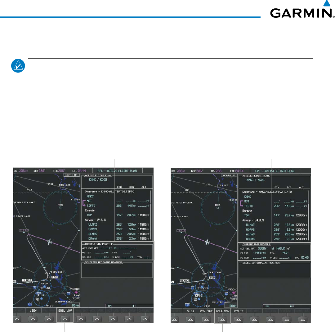
Garmin G1000 Pilot’s Guide for the Beechcraft 200/B200 Series
190-00928-04 Rev. A250
FLIGHT MANAGEMENT
5.7 VERTICAL NAVIGATION
NOTE: The G1000 supports vertical navigation for all lateral leg types except for CA, CI, FA, FM, HA, HM, PI,
VA, VD, VI, VR, and VM. Vertical constraints are not retained in stored flight plans.
The G1000 system Vertical Navigation (VNV) feature provides vertical profile guidance during the enroute
and teminal phases of flight. Guidance based on specified altitudes at waypoints in the active flight plan or to a
direct-to waypoint is provided. It includes vertical path guidance to a descending path, which is provided as a
linear deviation from the desired path. The desired path is defined by a line joining two waypoints with specified
altitudes or as a vertical angle from a specified waypoint/altitude. The vertical waypoints are integrated into the
active flight plan. Both manual and autopilot-coupled guidance are supported.
Figure 5-92 Enabling/Disabling Vertical Navigation
CNCL VNV Softkey
Current Vertical Navigation Profile
Disabled (fields dashed)
ENBL VNV Softkey
Current Vertical Navigation Profile
Enabled (valid data)
Enabling VNV guidance:
1) Press the FPL Key to display the Active Flight Plan Page on the MFD.
2) Select the ENBL VNV Softkey; or press the MENU Key, highlight ‘Enable VNV’, and press the ENT Key. Vertical
navigation is enabled, and vertical guidance begins with the waypoint shown in the CURRENT VNV PROFILE box
(defaults first waypoint in the active flight plan with an altitude enabled for vertical navigation (e.g., HABUK)).
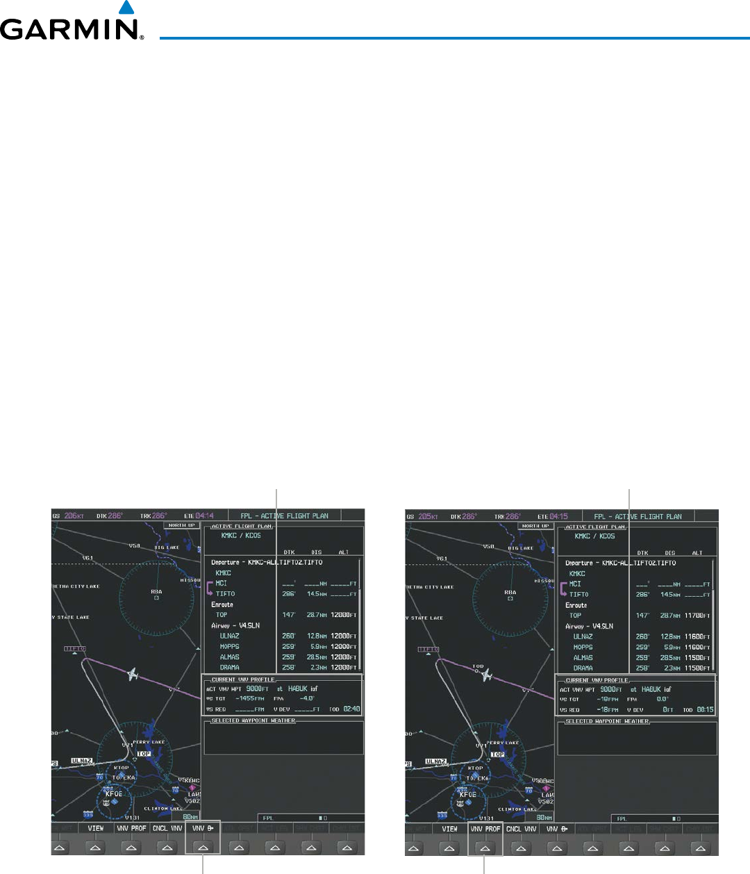
190-00928-04 Rev. A
Garmin G1000 Pilot’s Guide for the Beechcraft 200/B200 Series
251
FLIGHT MANAGEMENT
Disabling VNV guidance:
1) Press the FPL Key to display the Active Flight Plan Page on the MFD.
2) Select the CNCL VNV Softkey; or press the MENU Key, highlight ‘Cancel VNV’, and press the ENT Key. Vertical
navigation is disabled.
Canceling vertical navigation results in vertical deviation (V DEV), vertical speed required (VS REQ), and time
to top of descent/bottom of descent (TIME TO TOD/BOD) going invalid. The Vertical Deviation Indicator (VDI)
and Required Vertical Speed Indicator (RVSI) on the PFD are removed, and the V DEV, VS REQ, and TIME TO
TOD items displayed in the CURRENT VNV PROFILE box are dashed. VNV remains disabled until manually
enabled. Vertical guidance in reversionary mode can only be enabled for a direct-to waypoint.
The G1000 allows a vertical navigation direct-to to any waypoint in the active flight plan with an altitude
constraint “designated” for vertical guidance. Selecting the VNV Direct-to Softkey on the Active Flight Plan Page
allows the flight plan to be flown, while vertical guidance based on the altitude constraint at the VNV direct-to
waypoint is provided. The altitude change begins immediately and is spread along the flight plan from current
position to the vertical direct-to waypoint, not just along the leg for the direct-to waypoint. A direct-to with
altitude constraint activated by pressing the Direct-to Key also provides vertical guidance, but would bypass
flight plan waypoints between the current position in the flight plan and the direct-to waypoint. A top of descent
(TOD) point is computed based on the default flight path angle; descent begins once the TOD is reached.
Figure 5-93 Vertical Navigation Direct-To
Current Vertical Navigation Profile
Prior to VNV Direct-to
VNV Direct-To Softkey VNV PROF Softkey
Current Vertical Navigation Profile
After VNV Direct-to
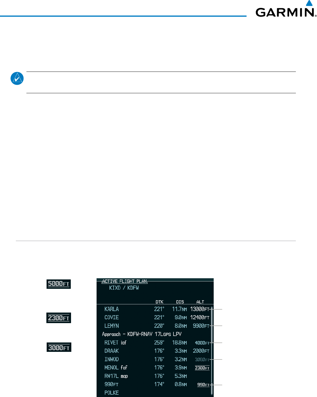
Garmin G1000 Pilot’s Guide for the Beechcraft 200/B200 Series
190-00928-04 Rev. A252
FLIGHT MANAGEMENT
Activating a vertical navigation direct-to:
1) Press the FPL Key to display the Active Flight Plan Page on the MFD.
2) Press the FMS Knob to activate the cursor and turn the FMS Knob to highlight the desired waypoint.
NOTE: The selected waypoint must have a designated altitude constraint (light blue number) to be used. If
not, the first waypoint in the flight plan with a designated altitude constraint is selected.
3) Select the VNV Direct-To Softkey; or press the MENU Key, highlight ‘VNV Direct-To’, and press the ENT Key.
An ‘Activate vertical Direct-to to: NNNNNFT at XXXXXX?’ confirmation window is displayed.
4) Press the ENT Key. Vertical guidance begins to the altitude constraint for the selected waypoint.
5) Press the FMS Knob to remove the flashing cursor.
The vertical navigation profile can be modified by directly entering a vertical speed target (VS TGT) and/or flight
path angle (FPA) in the CURRENT VNV PROFILE box.
Modifying the VS TGT and FPA:
1) Press the FPL Key to display the Active Flight Plan Page on the MFD.
2) Select the VNV PROF Softkey; or press the MENU Key, highlight ‘Select VNV Profile Window’, and press the
ENT Key. The cursor is now located in the CURRENT VNV PROFILE box.
3) Turn the FMS Knobs as needed to edit the values.
4) Press the FMS Knob to remove the flashing cursor.
ALTITUDE CONSTRAINTS
The G1000 system can use altitude constraints associated with lateral waypoints to give guidance for vertical
navigation. These altitudes are, depending on the specific instance, manually entered or retrieved from the
published altitudes in the navigation database.
Large Light Blue Text
Small White Text with
Altitude Restriction Bar
Large White Text
Small Light Blue
Subdued Text
Small Light Blue Text
Figure 5-94 Waypoint Altitude Constraints
Cross AT
or ABOVE
5,000 ft
Cross AT
or BELOW
3,000 ft
Cross AT
2,300 ft
Altitude Constraint
Examples
Displayed Text
Examples

190-00928-04 Rev. A
Garmin G1000 Pilot’s Guide for the Beechcraft 200/B200 Series
253
FLIGHT MANAGEMENT
White Text Light Blue Text Light Blue Subdued Text
Large
Text
Altitude calculated by the system
estimating the altitude of the aircraft as
it passes over the navigation point. This
altitude is provided as a reference and is
not designated to be used in determining
vertical speed and deviation guidance.
Altitude has been entered manually.
Altitude is designated for use in giving
vertical speed and deviation guidance.
Altitude does not match the published
altitude in navigation database or no
published altitude exists.
The system cannot use this
altitude in determining vertical
speed and deviation guidance
because of an invalid constraint
condition.
Small
Text
Altitude is not designated to be used in
determining vertical speed and deviation
guidance. Altitude has been retrieved
from the navigation database and is
provided as a reference.
Altitude is designated for use in giving
vertical speed and deviation guidance.
Altitude has been retrieved from the
navigation database or has been entered
manually and matches a published
altitude in the navigation database.
The system cannot use this
altitude in determining vertical
speed and deviation guidance
because of an invalid constraint
condition.
Table 5-8 Altitude Constraint Size and Color Coding
Altitudes associated with arrival and approach procedures are “auto-designated”. This means the system
automatically uses the altitudes loaded with the arrival or approach for giving vertical speed and deviation
guidance. Note that these altitudes are displayed as blue text up to, but not including, the FAF. The FAF is
always a “reference only” altitude and cannot be designated, unless the selected approach does not provide
vertical guidance. In this case, the FAF altitude can be designated.
Altitudes that have been designated for use in vertical guidance can be “un-designated” using the CLR Key.
The altitude is now displayed only as a reference. It is not used to give vertical guidance. Other displayed
altitudes may change due to re-calculations or be rendered invalid as a result of manually changing an altitude
to a non-designated altitude.
Designating a waypoint altitude to be used for vertical guidance:
1) Press the FPL Key to display the Active Flight Plan Page on the MFD.
2) Press the FMS Knob, and turn to highlight the desired waypoint altitude.
3) Turn the small FMS Knob to enter editing mode.
4) Press the ENT Key. The altitude is now shown in blue, indicating it is usable for vertical guidance.
Designating a procedure waypoint altitude to be used for vertical guidance:
1) Press the FPL Key to display the Active Flight Plan Page on the MFD.
2) Press the FMS Knob, and turn to highlight the desired waypoint altitude.
3) Press the ENT Key. The altitude is now shown in blue, indicating it is usable for vertical guidance.
Altitude constraints are displayed and entered in feet mean sea level (MSL) values to the nearest hundred. An
altitude constraint in feet above ground level (AGL) format is supported for airports. When a database altitude
restriction is displayed, the G1000 allows entry of a different altitude when creating a waypoint, effectively
overriding the database restriction (only before the FAF). When a database altitude restriction of type “AT or
ABOVE” or “AT or BELOW” is activated, the system uses the “AT” portion of the restriction to define the vertical
profile.

Garmin G1000 Pilot’s Guide for the Beechcraft 200/B200 Series
190-00928-04 Rev. A254
FLIGHT MANAGEMENT
An altitude constraint is invalid if:
• Meeting the constraint requires the aircraft to climb
• Meeting the constraint requires the maximum flight path angle (6° down) or maximum vertical speed (-6000
fpm) to be exceeded
• The altitude constraint results in a TOD behind the aircraft present position
• The constraint is within a leg type for which altitude constraints are not supported
• The altitude constraint is added to the FAF of an approach that provides vertical guidance (i.e., ILS or GPS
SBAS approach)
• The altitude constraint is added to a waypoint past the FAF.
Entering/modifiying an altitude constraint:
1) Press the FPL Key to display the Active Flight Plan Page on the MFD.
2) Press the FMS Knob, and turn to highlight the desired waypoint altitude constraint.
3) Enter an altitude constraint value using the FMS Knobs. To enter altitudes as a flight level, turn the small
FMS Knob counter-clockwise past zero or clockwise past 9 on the first character, and the system automatically
changes to show units of Flight Level. Turn the large FMS Knob clockwise to highlight the first zero and enter
the three digit flight level.
4) Press the ENT Key to accept the altitude constraint; if the selected waypoint is an airport, an additional choice
is displayed. Turn the small FMS Knob to choose ‘MSL’ or ‘AGL’, and press the ENT Key to accept the altitude.
Altitude constraints can be modified or deleted after having been added to the flight plan. In the event
an altitude constraint is deleted and the navigation database contains an altitude restriction for the lateral
waypoint, the G1000 displays the altitude restriction from the database provided no predicted altitude
can be provided. The G1000 also provides a way to reinstate a published altitude constraint that has been
edited.
Deleting an altitude constraint provided by the navigation database:
1) Press the FPL Key to display the Active Flight Plan Page on the MFD.
2) Press the FMS Knob, and turn to highlight the desired waypoint altitude constraint.
3) Press the CLR Key. A ‘Remove VNV altitude constraint?’ confirmation window is displayed.
4) Select ‘OK’ and press the ENT Key.

190-00928-04 Rev. A
Garmin G1000 Pilot’s Guide for the Beechcraft 200/B200 Series
255
FLIGHT MANAGEMENT
Deleting an altitude constraint that has been manually entered:
1) Press the FPL Key to display the Active Flight Plan Page on the MFD.
2) Press the FMS Knob, and turn to highlight the desired waypoint altitude constraint.
3) Press the CLR Key. A ‘Remove or Revert to published VNV altitude of nnnnnFT?’ confirmation window is
displayed.
4) Select ‘REMOVE’ and press the ENT Key. The manually entered altitude is deleted (it is replaced by a system
calculated altitude, if available).
Reverting a manually entered altitude constraint back to the navigation database value:
1) Press the FPL Key to display the Active Flight Plan Page on the MFD.
2) Press the FMS Knob, and turn to highlight the desired waypoint altitude constraint.
3) Press the CLR Key. A ‘Remove or Revert to published VNV altitude of nnnnnFT?’ confirmation window is
displayed.
4) Select ‘REVERT’ and press the ENT Key. The altitude is changed to the navigation database value.
5) Press the FMS Knob to remove the flashing cursor.
Modifying a system calculated altitude constraint:
1) Press the FPL Key to display the Active Flight Plan Page on the MFD.
2) Press the FMS Knob, and turn to highlight the desired waypoint altitude constraint.
3) Press the CLR Key. An ‘Edit or Revert to published VNV altitude of nnnnnFT?’ confirmation window is
displayed.
4) Select ‘EDIT’ and press the ENT Key.
5) Edit the value using the FMS Knobs, and press the ENT Key.
6) Press the FMS Knob to remove the flashing cursor.

Garmin G1000 Pilot’s Guide for the Beechcraft 200/B200 Series
190-00928-04 Rev. A256
FLIGHT MANAGEMENT
5.8 PROCEDURES
The G1000 can access the whole range of instrument procedures available. Departures (DPs), arrivals (STARs),
and non-precision and precision approaches (APPRs) are stored within the database and can be loaded using any
Procedures (PROC) Key.
The selected procedure for the departure or arrival airport is added to the active flight plan. No waypoints are
required to be in the active flight plan to load procedures; however, if the departure and arrival airport are already
loaded, the procedure loading window defaults to the appropriate airport, saving some time selecting the correct
airport on the Procedure Loading Page. Whenever an approach is selected, the choice to either “load” or “activate”
is given. “Loading” adds the approach to the end of the flight plan without immediately using it for navigation
guidance. This allows continued navigation via the intermediate waypoints in the original flight plan, but keeps
the procedure available on the Active Flight Plan Page for quick activation when needed. “Activating” also adds
the procedure to the end of the flight plan but immediately begins to provide guidance to the first waypoint in
the approach.
DEPARTURES
A Departure Procedure (DP) is loaded at the departure airport in the flight plan. Only one departure can be
loaded at a time in a flight plan. If a departure is loaded when another departure is already in the active flight
plan, the new departure replaces the previous departure. The route is defined by selection of a departure, the
transition waypoints, and a runway.
LOADING A DEPARTURE INTO THE ACTIVE FLIGHT PLAN
Loading a departure into the active flight plan using the PROC Key:
1) Press the PROC Key. The Procedures Window is displayed.
2) Highlight ‘SELECT DEPARTURE’.
3) Press the ENT Key. The Departure Loading Page is displayed.
4) Use the FMS Knob to select an airport and press the ENT Key.
5) Select a departure from the list and press the ENT Key.
6) Select a runway (if required) and press the ENT Key.
7) Select a transition (if required) and press the ENT Key. ‘LOAD?’ is highlighted.
8) Press the ENT Key to load the departure procedure.
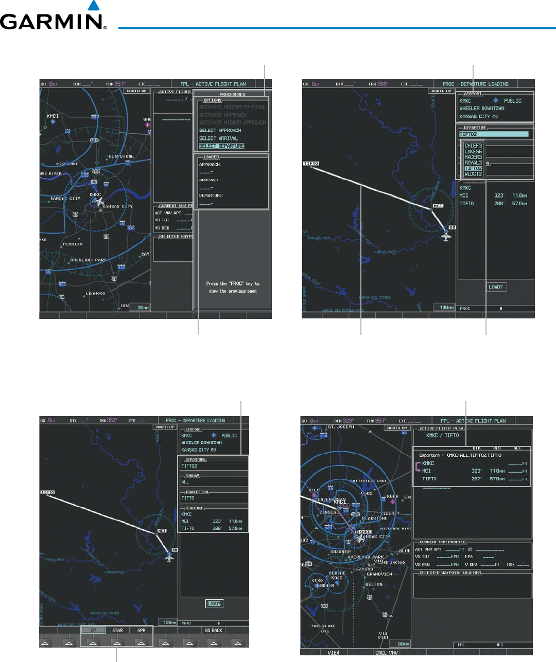
190-00928-04 Rev. A
Garmin G1000 Pilot’s Guide for the Beechcraft 200/B200 Series
257
FLIGHT MANAGEMENT
Figure 5-95 Departure Selection
Departure Airport
Departure Preview
Available Procedure Actions
Departure Choices
Loaded Procedures
Procedure Loading Page Selection Softkeys
Figure 5-96 Departure Loading
Loaded Departure
Selected Departure

Garmin G1000 Pilot’s Guide for the Beechcraft 200/B200 Series
190-00928-04 Rev. A258
FLIGHT MANAGEMENT
Viewing available departures at an airport:
1) From the Airport Information Page (first page in the WPT group), select the DP Softkey. The Departure Information
Page is displayed, defaulting to the airport displayed on the Airport information Page.
2) To select another airport, press the FMS Knob to activate the cursor, enter an identifier/facility name/city, and
press the ENT Key.
3) Turn the large FMS Knob to highlight the Departure. The departure is previewed on the map.
4) Turn the small FMS Knob to view the available departures. Press the ENT Key to select the departure. The cursor
moves to the Runway box. The departure is previewed on the map.
5) Turn the small FMS Knob to view the available runways. Press the ENT Key to select the runway. The cursor
moves to the Transition box (only if there are available transitions). The departure is previewed on the map.
6) Turn the small FMS Knob to view the available transitions. Press the ENT Key to select the transition. The cursor
moves to the Sequence box. The departure is previewed on the map.
7) Select the INFO-x Softkey to return to the Airport Information Page.
REMOVING A DEPARTURE FROM THE ACTIVE FLIGHT PLAN
When plans change while flying IFR, departures can be easily removed from the Active Flight Plan.
Removing a departure procedure from the active flight plan:
1) Press the FPL Key to display the Active Flight Plan Page (MFD) or the Active Flight Plan Window (PFD).
2) Press the MENU Key, and highlight ‘Remove Departure’.
3) Press the ENT Key. A confirmation window is displayed listing the departure procedure.
4) With ‘OK’ highlighted, press the ENT Key. To cancel the removal request, highlight ‘CANCEL’ and press the ENT
Key.
Or:
1) Press the FPL Key to display the Active Flight Plan Page (MFD) or the Active Flight Plan Window (PFD).
2) Press the FMS Knob, and turn to highlight the departure header in the active flight plan.
3) Press the CLR Key. A confirmation window is displayed listing the departure procedure.
4) With ‘OK’ highlighted, press the ENT Key. To cancel the removal request, highlight ‘CANCEL’ and press the ENT
Key.
5) Press the FMS Knob to remove the flashing cursor.
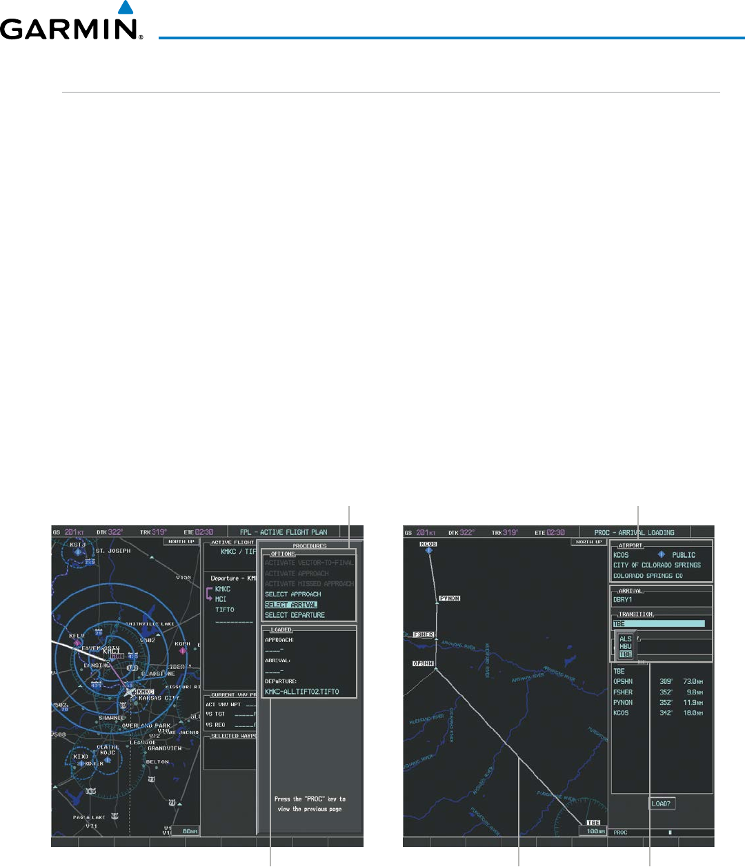
190-00928-04 Rev. A
Garmin G1000 Pilot’s Guide for the Beechcraft 200/B200 Series
259
FLIGHT MANAGEMENT
ARRIVALS
A Standard Terminal Arrival (STAR) can be loaded at any airport that has one available. Only one arrival
can be loaded at a time in a flight plan. If an arrival is loaded when another arrival is already in the active
flight plan, the new arrival replaces the previous arrival. The route is defined by selection of an arrival, the
transition waypoints, and a runway.
LOADING AN ARRIVAL INTO THE ACTIVE FLIGHT PLAN
Loading an arrival into the active flight plan using the PROC Key:
1) Press the PROC Key. The Procedures Window is displayed.
2) Highlight ‘SELECT ARRIVAL’.
3) Press the ENT Key. The Arrival Loading Page is displayed.
4) Use the FMS Knob to select an airport and press the ENT Key.
5) Select an arrival from the list and press the ENT Key.
6) Select a transition (if required) and press the ENT Key.
7) Select a runway (if required) and press the ENT Key. ‘LOAD?’ is highlighted.
8) Press the ENT Key to load the arrival procedure.
Figure 5-97 Arrival Selection
Destination Airport
Arrival Preview
Available Procedure Actions
Arrival Choices
Loaded Procedures
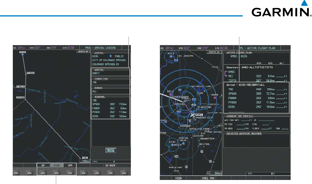
Garmin G1000 Pilot’s Guide for the Beechcraft 200/B200 Series
190-00928-04 Rev. A260
FLIGHT MANAGEMENT
Figure 5-98 Arrival Loading
Loaded ArrivalSelected Arrival
Procedure Loading Page Selection Softkeys
Viewing available arrivals at an airport:
1) From the Airport Information Page (first page in the WPT group), select the STAR Softkey. The Arrival Information
Page is displayed, defaulting to the airport displayed on the Airport Information Page.
2) To select another airport, press the FMS Knob to activate the cursor, enter an identifier/facility name/city, and
press the ENT Key.
3) Turn the large FMS Knob to highlight the Arrival. The arrival is previewed on the map.
4) Turn the small FMS Knob to view the available arrivals. Press the ENT Key to select the arrival. The cursor moves
to the Transition box. The arrival is previewed on the map.
5) Turn the small FMS Knob to view the available transitions. Press the ENT Key to select the transition. The cursor
moves to the Runway box. The arrival is previewed on the map.
6) Turn the small FMS Knob to view the available runways. Press the ENT Key to select the runway. The cursor
moves to the Sequence box. The arrival is previewed on the map.
7) Select the INFO-x Softkey to return to the Airport Information Page.

190-00928-04 Rev. A
Garmin G1000 Pilot’s Guide for the Beechcraft 200/B200 Series
261
FLIGHT MANAGEMENT
REMOVING AN ARRIVAL FROM THE ACTIVE FLIGHT PLAN
When plans change while flying IFR, arrivals can be easily removed from the Active Flight Plan.
Removing an arrival from the active flight plan:
1) Press the FPL Key to display the Active Flight Plan Page (MFD) or the Active Flight Plan Window (PFD).
2) Press the MENU Key, and highlight ‘Remove Arrival’.
3) Press the ENT Key. A confirmation window is displayed listing the arrival procedure.
4) With ‘OK’ highlighted, press the ENT Key. To cancel the removal request, highlight ‘CANCEL’ and press the ENT
Key.
Or:
1) Press the FPL Key to display the Active Flight Plan Page (MFD) or the Active Flight Plan Window (PFD).
2) Press the FMS Knob, and turn to highlight the arrival header in the active flight plan.
3) Press the CLR Key. A confirmation window is displayed listing the arrival procedure.
4) With ‘OK’ highlighted, press the ENT Key. To cancel the removal request, highlight ‘CANCEL’ and press the ENT
Key.
5) Press the FMS Knob to remove the flashing cursor.
APPROACHES
NOTE: If certain GPS parameters (SBAS, RAIM, etc.) are not available, some published approach procedures
for the desired airport may not be displayed in the list of available approaches.
An Approach Procedure (APPR) can be loaded at any airport that has one available, and provides guidance
for non-precision and precision approaches to airports with published instrument approach procedures.
Only one approach can be loaded at a time in a flight plan. If an approach is loaded when another approach
is already in the active flight plan, the new approach replaces the previous approach. The route is defined by
selection of an approach and the transition waypoints.
Whenever an approach is selected, the choice to either “load” or “activate” is given. “Loading” adds the
approach to the end of the flight plan without immediately using it for navigation guidance. This allows
continued navigation via the intermediate waypoints in the original flight plan, but keeps the procedure
available on the Active Flight Plan Page for quick activation when needed. “Activating” also adds the
procedure to the end of the flight plan but immediately begins to provide guidance to the first waypoint in
the approach.
When selecting an approach, a “GPS” designation to the right of the procedure name indicates the procedure
can be flown using the GPS receiver. Some procedures do not have this designation, meaning the GPS
receiver can be used for supplemental navigation guidance only. If the GPS receiver cannot be used for
primary guidance, the appropriate navigation receiver must be used for the selected approach (e.g., VOR or
ILS). The final course segment of ILS approaches, for example, must be flown by tuning the NAV receiver to
the proper frequency and selecting that NAV receiver on the CDI.
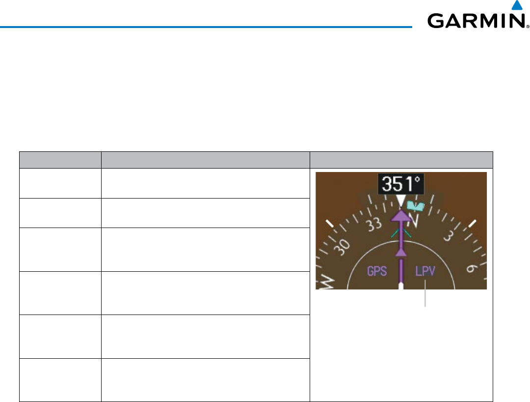
Garmin G1000 Pilot’s Guide for the Beechcraft 200/B200 Series
190-00928-04 Rev. A262
FLIGHT MANAGEMENT
The SBAS GPS allows for flying LNAV, LNAV+V, LNAV/VNAV, LP, LP+V, and LPV approach service levels
according to the published chart. LNAV+V is an LNAV with advisory vertical guidance provided for assistance
in maintaining a constant vertical glidepath similar to an ILS glideslope on approach. This guidance is
displayed on the system PFD in the same location as the ILS glideslope using a magenta diamond. In all cases
where LNAV+V is indicated by the system during an approach, LNAV minima are used. The active approach
service level is annunciated on the HSI as shown in the following table:
HSI Annunciation Description Example on HSI
LNAV RNAV GPS approach using published LNAV
minima
Approach Service Level
- LNAV, LNAV+V, L/VNAV, LP, LP+V, LPV
LNAV+V RNAV GPS approach using published LNAV
minima. Advisory vertical guidance is provided
L/VNAV
(available only if
SBAS available)
RNAV GPS approach using published LNAV/
VNAV minima (downgrades to Baro VNAV if
SBAS unavailable)
LP
(available only if
SBAS available)
RNAV GPS approach using published LP minima
(downgrades to LNAV if SBAS unavailable)
LP+V
(available only if
SBAS available)
RNAV GPS approach using published LP minima
Advisory vertical guidance is provided
(downgrades to LNAV if SBAS unavailable)
LPV
(available only if
SBAS available)
RNAV GPS approach using published LPV
minima
Table 5-9 Approach Service Levels
LOADING AN APPROACH INTO THE ACTIVE FLIGHT PLAN
Loading an approach into the active flight plan using the PROC Key:
1) Press the PROC Key. The Procedures Window is displayed.
2) Highlight ‘SELECT APPROACH’, and press the ENT Key. The Approach Loading Page is displayed.
3) Select the airport and approach:
a) Use the FMS Knob to select an airport and press the ENT Key.
b) Select an approach from the list and press the ENT Key.
Or:
a) If necessary, push the FMS Knob to exit the approach list, and use the large FMS Knob to move the cursor to
the APPROACH CHANNEL field.
b) Use the FMS Knob to enter the approach channel number, and press the ENT Key to accept the approach
channel number. The airport and approach are selected.
4) Select a transition (if required) and press the ENT Key.
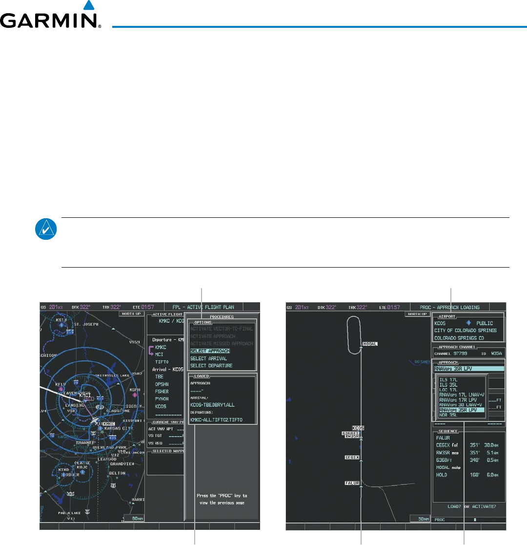
190-00928-04 Rev. A
Garmin G1000 Pilot’s Guide for the Beechcraft 200/B200 Series
263
FLIGHT MANAGEMENT
5) Minimums
a) To set ‘MINIMUMS’, turn the small FMS Knob to select ‘BARO’ or ‘TEMP COMP’, and press the ENT Key. Turn
the small FMS Knob to select the altitude, and press the ENT Key.
b) If ‘TEMP COMP’ was selected, the cursor moves to the temperature field. Turn the small FMS Knob to select the
temperature, and press the ENT Key.
Or:
a) To skip setting minimums, press the ENT Key.
6) Press the ENT Key with ‘LOAD?’ highlighted to load the approach procedure; or turn the large FMS Knob to
highlight ‘ACTIVATE’ and press the ENT Key to load and activate the approach procedure.
NOTE: When GPS is not approved for the selected final approach course, the message ‘NOT APPROVED
FOR GPS’ is displayed. GPS provides guidance to the approach, but the HSI must to be switched to a NAV
receiver to fly the final course of the approach.
Figure 5-99 Approach Selection
Destination Airport
Approach Preview
Available Procedure Actions
Approach Choices
Loaded Procedures
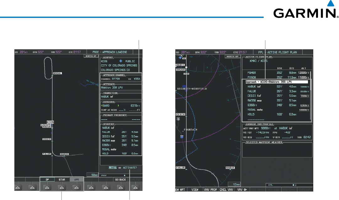
Garmin G1000 Pilot’s Guide for the Beechcraft 200/B200 Series
190-00928-04 Rev. A264
FLIGHT MANAGEMENT
Figure 5-100 Approach Loading
Loaded ApproachSelected Approach
LOAD or ACTIVATE? AnnunciationProcedure Loading Page Selection Softkeys
Viewing available approaches at an airport:
1) From the Airport Information Page (first page in the WPT group), press the APR Softkey. The Approach
Information Page is displayed, defaulting to the airport displayed on the Airport information Page.
2) To select another airport, press the FMS Knob to activate the cursor, enter an identifier/facility name/city, and
press the ENT Key.
3) Press the FMS Knob, then turn the large FMS Knob to highlight the Approach. The approach is previewed on
the map.
4) Turn the small FMS Knob to view the available approaches. Press the ENT Key to select the approach. The
cursor moves to the Transition box. The approach is previewed on the map.
5) Turn the small FMS Knob to view the available transitions. Press the ENT Key to select the transition. The cursor
moves to the Minimums box. The approach is previewed on the map.
6) Turn the small FMS Knob to select minimums on or off. Press the ENT Key.
a) When minimums are selected on, the cursor moves to the minimum altitude field . Use the small FMS Knob to
select the altitude. Press the ENT Key.
b) If temperature compensated minimums was selected, the cursor moves to the temperature field. Use the small
FMS Knob to select the temperature. Press the ENT Key. The cursor moves to the Sequence box. The approach
is previewed on the map.
Or:
a) When minimums are selected off, the cursor moves to the Sequence box. The approach is previewed on the
map.
7) Press the INFO-1 or the INFO-2 Softkey to return to the Airport Information Page.

190-00928-04 Rev. A
Garmin G1000 Pilot’s Guide for the Beechcraft 200/B200 Series
265
FLIGHT MANAGEMENT
Loading an approach into the active flight plan from the Nearest Airport Page:
1) Select the Nearest Airports Page.
2) Press the FMS Knob, then turn the large FMS Knob to highlight the desired nearest airport. The airport is
previewed on the map.
3) Press the APR Softkey; or press the MENU Key, highlight ‘Select Approach Window’, and press the ENT Key.
4) Turn the FMS Knob to highlight the desired approach.
5) Press the LD APR Softkey; or press the MENU Key, highlight ‘Load Approach’, and press the ENT Key. The
Approach Loading Page is displayed with the transitions field highlighted.
6) Turn the FMS Knob to highlight the desired transition, and press the ENT Key.
7) Minimums
a) To set ‘MINIMUMS’, turn the small FMS Knob to select ‘BARO’ or ‘TEMP COMP’, and press the ENT Key. Turn
the small FMS Knob to select the altitude, and press the ENT Key.
b) If ‘TEMP COMP’ was selected, the cursor moves to the temperature field. Turn the small FMS Knob to select the
temperature, and press the ENT Key.
Or:
a) To skip setting minimums, press the ENT Key. The ‘LOAD?’ field is highlighted.
8) Press the ENT Key with ‘LOAD?’ highlighted to load the approach procedure; or turn the large FMS Knob to
highlight ‘ACTIVATE’ and press the ENT Key to load and activate the approach procedure. The system continues
navigating the current flight plan until the approach is activated. When GPS is not approved for the selected
final approach course, the message ‘NOT APPROVED FOR GPS’ is displayed. GPS provides guidance to the
approach, but the HSI must to be switched to a NAV receiver to fly the final course of the approach.
ACTIVATING AN APPROACH
A previously loaded approach can be activated from the Procedures Window.
Activating a previously loaded approach:
1) Press the PROC Key. The Procedures Window is displayed with ‘Activate Approach’ highlighted.
2) Press the ENT Key to activate the approach.
In many cases, it may be easiest to “load” the full approach while still some distance away, enroute to the
destination airport. Later, if vectored to final, use the steps above to select ‘Activate Vector-To-Final’ — which
makes the inbound course to the FAF waypoint active.
Activating a previously loaded approach with vectors to final:
1) Press the PROC Key to display the Procedures Window.
2) Highlight ‘ACTIVATE VECTOR-TO-FINAL’ and press the ENT Key.

Garmin G1000 Pilot’s Guide for the Beechcraft 200/B200 Series
190-00928-04 Rev. A266
FLIGHT MANAGEMENT
Loading and activating an approach using the MENU Key:
1) From the Approach Loading Page, press the MENU Key. The page menu is displayed with ‘Load & Activate
Approach’ highlighted.
2) Press the ENT Key. When GPS is not approved for the selected final approach course, the message ‘NOT
APPROVED FOR GPS’ is displayed. GPS provides guidance to the approach, but the HSI must to be switched to
a NAV receiver to fly the final course of the approach.
REMOVING AN APPROACH FROM THE ACTIVE FLIGHT PLAN
When plans change while flying IFR, approaches can be easily removed from the Active Flight Plan.
Removing an approach from the active flight plan:
1) Press the FPL Key to display the Active Flight Plan Page (MFD) or the Active Flight Plan Window (PFD).
2) Press the MENU Key, and highlight ‘Remove Approach’.
3) Press the ENT Key. A confirmation window is displayed listing the approach procedure.
4) With ‘OK’ highlighted, press the ENT Key. To cancel the removal, highlight ‘CANCEL’ and press the ENT Key.
Or:
1) Press the FPL Key to display the Active Flight Plan Page (MFD) or the Active Flight Plan Window (PFD).
2) Press the FMS Knob, and turn to highlight the approach header in the active flight plan.
3) Press the CLR Key. A confirmation window is displayed listing the approach procedure.
4) With ‘OK’ highlighted, press the ENT Key. To cancel the removal, highlight ‘CANCEL’ and press the ENT Key.
5) Press the FMS Knob to remove the flashing cursor.
MISSED APPROACH
Activating a missed approach in the active flight plan:
1) Press the PROC Key.
2) Turn the FMS Knob to highlight ‘ACTIVATE MISSED APPROACH’.
3) Press the ENT Key. The aircraft automatically sequences to the MAHP.
Or:
Press the Go-Around Button.
TEMPERATURE COMPENSATED ALTITUDE
Temperature compensated altitudes can be computed and used for a loaded approach. A temperature
compensated altitude is displayed in slanted text.
Enabling temperature compensated altitude:
1) From the Active Flight Plan Page, press the MENU Key. The Page Menu is displayed.
2) Turn the FMS Knob to highlight ‘Temperature Compensation’.
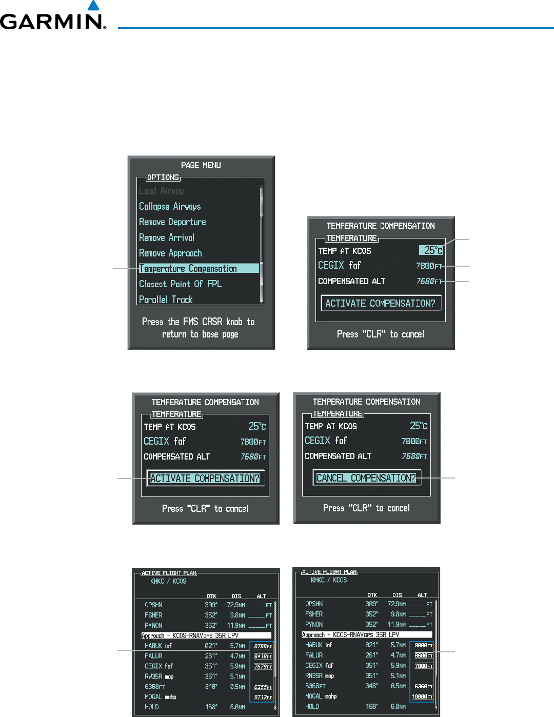
190-00928-04 Rev. A
Garmin G1000 Pilot’s Guide for the Beechcraft 200/B200 Series
267
FLIGHT MANAGEMENT
3) Press the ENT Key. The TEMPERATURE COMPENSATION Window is displayed.
4) Use the small FMS Knob to select the temperature at the <airport>. The compensated altitude is computed as
the temperature is selected.
5) Press the ENT Key. ‘ACTIVATE COMPENSATION?’ is highlighted.
6) Press the ENT Key. The compensated altitudes for the approach are shown in the flight plan.
Temperature
Compensation
Selected
Figure 5-101 Temperature Compensation
Selected
Temperature
FAF Altitude
Compensated
Altitude
ACTIVATE
COMPENSATION?
Highlighted
Figure 5-102 Activating/Cancelling Temperature Compensation
CANCEL
COMPENSATION?
Highlighted
Compensated
Altitudes
Figure 5-103 Temperature Compensation in the Active Flight Plan
Uncompensated
Altitudes
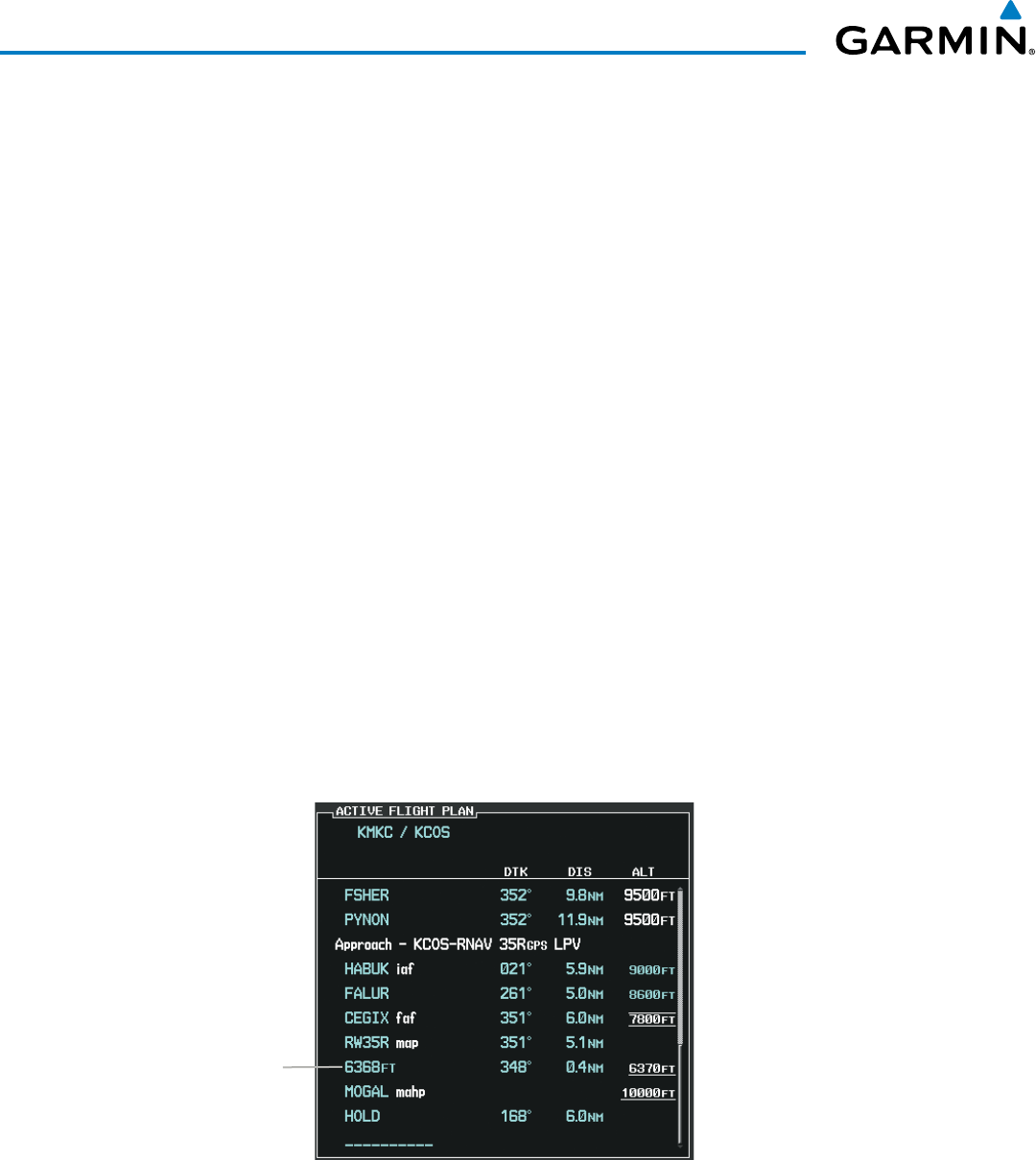
Garmin G1000 Pilot’s Guide for the Beechcraft 200/B200 Series
190-00928-04 Rev. A268
FLIGHT MANAGEMENT
Disabling temperature compensated altitude:
1) From the Active Flight Plan Page, press the MENU Key. The Page Menu is displayed.
2) Turn the FMS Knob to highlight ‘Temperature Compensation’.
3) Press the ENT Key. The TEMPERATURE COMPENSATION Window is displayed.
4) Press the ENT Key. ‘CANCEL COMPENSATION?’ is highlighted.
5) Press the ENT Key. The temperature compensated altitude at the FAF is cancelled.
COURSE TO ALTITUDE
In this missed approach procedure, the altitude immediately following the MAP (in this case ‘6368ft’) is
not part of the published procedure. It is simply a Course to Altitude (CA) leg which guides the aircraft along
the runway centerline until the altitude required to safely make the first turn toward the MAHP is exceeded.
This altitude is provided by Jeppesen, and may be below, equal to, or above the published minimums for
this approach. In this case, if the aircraft altitude is below the specified altitude (6,368 feet) after crossing
the MAP, a direct-to is established to provide a course on runway heading until an altitude of 6,368 feet is
reached. After reaching 6,368 feet, a direct-to is established to the published MAHP (in this case MOGAL).
If the aircraft altitude is above the specified altitude after crossing the MAP, a direct-to is established to the
published fix (MOGAL) to begin the missed approach procedure.
In some missed approach procedures this Course to Altitude leg may be part of the published procedure.
For example, a procedure may dictate a climb to 5,500 feet, then turn left and proceed to the Missed Approach
Hold Point (MAHP). In this case, the altitude would appear in the list of waypoints as ‘5500ft’. Again, if the
aircraft altitude is lower than the prescribed altitude, a direct-to is established on a Course to Altitude leg
when the missed approach procedure is activated.
Figure 5-104 Course to Altitude
Course to Altitude Leg
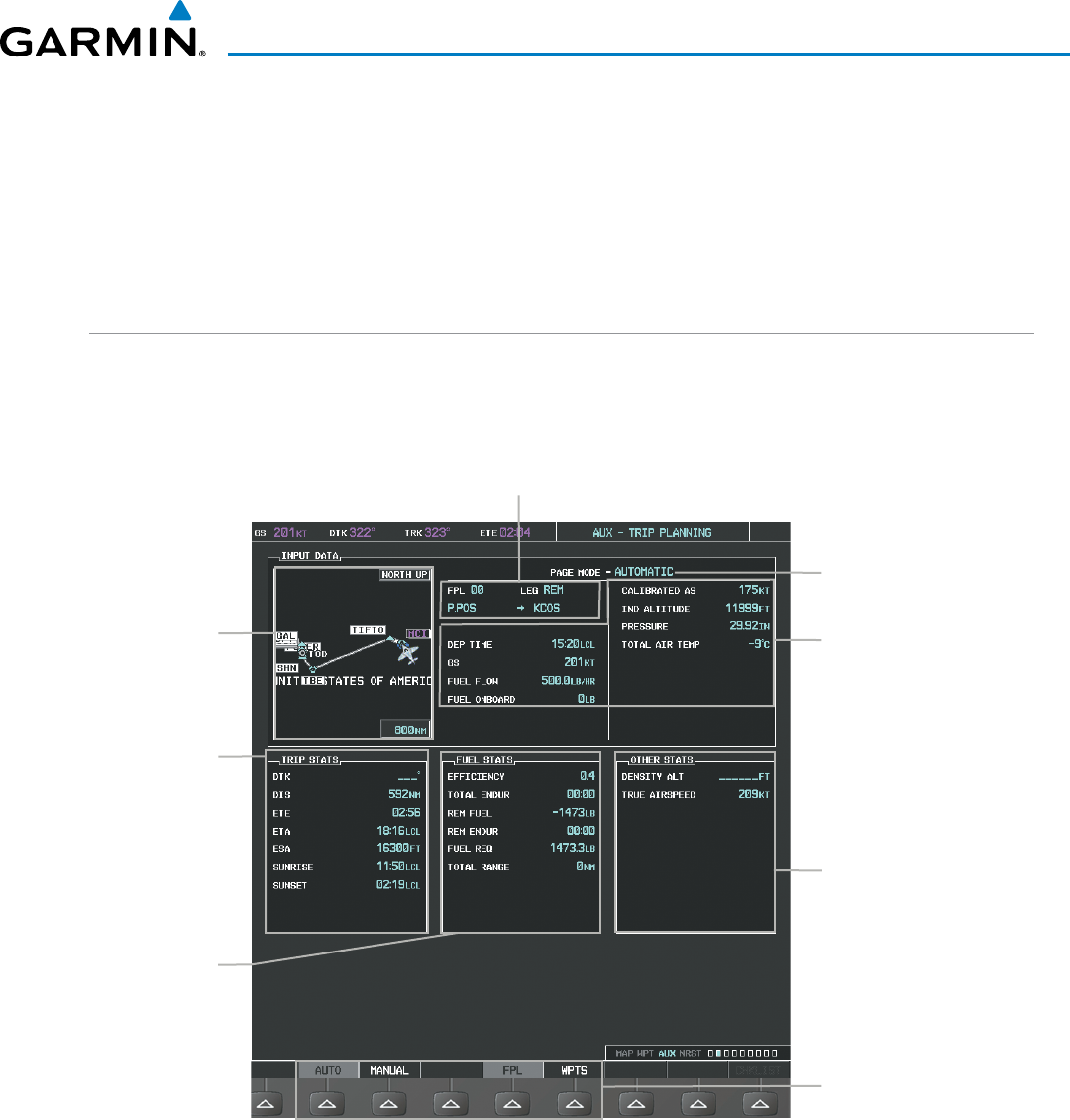
190-00928-04 Rev. A
Garmin G1000 Pilot’s Guide for the Beechcraft 200/B200 Series
269
FLIGHT MANAGEMENT
5.9 TRIP PLANNING
The G1000 allows the pilot to view trip planning information, fuel information, and other information for
a specified flight plan or flight plan leg based on automatic data, or based on manually entered data. Weight
planning is also available, based on manually entered fuel data and the active flight plan (to estimate remaining
fuel).
TRIP PLANNING
All of the input of data needed for calculation and viewing of the statistics is done on the Trip Planning Page
located in the AUX Page Group.
Figure 5-105 Trip Planning Page
Trip Statistics
Desired Track -
Distance -
Est. Time Enroute -
Est. Time of Arrival -
Enroute Safe Altitude -
Sunrise Time (local) -
Sunset Time (local) -
Trip Input Data (sensor/pilot)
- Departure Time (local)
- Ground Speed
- Fuel Flow
- Fuel On Board Aircraft
- Calibrated Airspeed
- Indicated Altitude
- Barometric Pressure
- Total Air Temperature
Softkeys
- Automatic/Manual Page Mode
- Flight Plan/Waypoint Mode
Preview of Selected
Flight Plan/
Flight Plan Leg
Trip Planning Page Mode
- Automatic/Manual
Selected Flight Plan Segment
- FPL Number/Cumulative Legs (CUM or REM) or Leg Number (NN)
- Waypoints Defining Selected Flight Plan/Flight Plan Leg
Fuel Statistics
Efficiency -
Total Endurance -
Remaining Fuel -
Remaining Endurance -
Fuel Required -
Total Range -
Other Statistics
- Density Altitude
- True Airspeed (TAS)
The trip planning inputs are based on sensor inputs (automatic page mode) or on pilot inputs (manual page
mode). Some additional explanation of the sources for some of the inputs is as follows:
• Departure time (DEP TIME) - This defaults to the current time in automatic page mode. The computations
are from the aircraft present position, so the aircraft is always just departing.

Garmin G1000 Pilot’s Guide for the Beechcraft 200/B200 Series
190-00928-04 Rev. A270
FLIGHT MANAGEMENT
• Calibrated airspeed (CALIBRATED AS) - The primary source is from the air data system, and the secondary
source of information is GPS ground speed.
• Indicated altitude (IND ALTITUDE) - The primary source is the barometric altitude, and the secondary source
of information is GPS altitude.
TRIP STATISTICS
The trip statistics are calculated based on the selected starting and ending waypoints and the trip planning
inputs.
In flight plan mode (FPL) with a stored flight plan selected (NN), and the entire flight plan (CUM) selected,
the waypoints are the starting and ending waypoints of the selected flight plan.
In flight plan mode (FPL) with a stored flight plan selected (NN), and a specific leg (NN) selected, the
waypoints are the endpoints of the selected leg.
In flight plan mode (FPL) with the active flight plan selected (00), and the remaining flight plan (REM)
selected, the ‘from’ waypoint is the present position of the aircraft and the ‘to’ waypoint is the endpoint of the
active flight plan.
In flight plan mode (FPL) with the active flight plan selected (00), and a specific leg (NN) selected, the
‘from’ waypoint is the current aircraft position and the ‘to’ waypoint is the endpoint of the selected leg.
In waypoint (WPTS) mode these are manually selected waypoints (if there is an active flight plan, these
default to the endpoints of the active leg).
Some of the calculated trip statistics are dashed when the selected leg of the active flight plan has already
been flown.
• Desired Track (DTK) - DTK is shown as nnn° and is the desired track between the selected waypoints.
It is dashed unless only a single leg is selected.
• Distance (DIS) - The distance is shown in tenths of units up to 99.9, and in whole units up to 9999.
• Estimated time enroute (ETE) - ETE is shown as hours:minutes until less than an hour, then it is shown
as minutes:seconds.
• Estimated time of arrival (ETA) - ETA is shown as hours:minutes and is the local time at the
destination.
- If in waypoint mode then the ETA is the ETE added to the departure time.
- If a flight plan other than the active flight plan is selected it shows the ETA by adding to the departure
time all of the ETEs of the legs up to and including the selected leg. If the entire flight plan is selected,
then the ETA is calculated as if the last leg of the flight plan was selected.
- If the active flight plan is selected the ETA reflects the current position of the aircraft and the current
leg being flown. The ETA is calculated by adding to the current time the ETEs of the current leg up to
and including the selected leg. If the entire flight plan is selected, then the ETA is calculated as if the
last leg of the flight plan was selected.
• Enroute safe altitude (ESA) - The ESA is shown as nnnnnFT
• Destination sunrise and sunset times (SUNRISE, SUNSET) - These times are shown as hours:minutes
and are the local time at the destination.
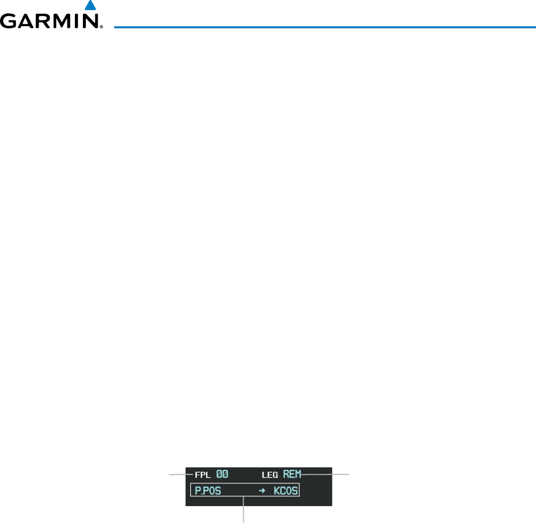
190-00928-04 Rev. A
Garmin G1000 Pilot’s Guide for the Beechcraft 200/B200 Series
271
FLIGHT MANAGEMENT
FUEL STATISTICS
The fuel statistics are calculated based on the selected starting and ending waypoints and the trip planning
inputs. Some of the calculated trip statistics are dashed when the selected leg of the active flight plan has
already been flown.
• Fuel efficiency (EFFICIENCY) - This value is calculated by dividing the current ground speed by the
current fuel flow.
• Time of fuel endurance (TOTAL ENDUR) - This time is shown as hours:minutes. This value is obtained
by dividing the amount of fuel on board by the current fuel flow.
• Fuel on board upon reaching end of selected leg (REM FUEL) - This value is calculated by taking the
amount of fuel onboard and subtracting the fuel required to reach the end of the selected leg.
• Fuel endurance remaining at end of selected leg (REM ENDUR) - This value is calculated by taking the time
of fuel endurance and subtracting the estimated time enroute to the end of the selected leg.
• Fuel required for trip (FUEL REQ) - This value is calculated by multiplying the time to go by the fuel
flow.
• Total range at entered fuel flow (TOTAL RANGE) - This value is calculated by multiplying the time of fuel
endurance by the ground speed.
OTHER STATISTICS
These statistics are calculated based on the system sensor inputs or the manual trip planning inputs.
• Density altitude (DENSITY ALT)
• True airspeed (TRUE AIRSPEED)
The pilot may select automatic (AUTO) or manual (MANUAL) page mode, and flight plan (FPL) or waypoint
(WPTS) mode. In automatic page mode, only the FPL, LEG, or waypoint IDs are editable (based on FPL/WPTS
selection).
Figure 5-106 Trip Planning Page - Flight Plan Mode
Selected Leg(s)
Stored Flight Plan
- CUM: Beginning to End of FPL
- NN: Beginning to End of Selected Leg
Active Flight Plan
- REM: Pres. Pos. to End of FPL
- NN: Pres. Pos. to End of Selected Leg
Starting and Ending Waypoint of
Selected Flight Plan Segment
Selected Flight Plan
NN -
00 is Active FPL
01-99 are Stored FPLs

Garmin G1000 Pilot’s Guide for the Beechcraft 200/B200 Series
190-00928-04 Rev. A272
FLIGHT MANAGEMENT
Figure 5-107 Trip Planning Page - Waypoint Mode
Selected Leg(s)
Not Available
Selected Starting and Ending Waypoints
Selected Flight Plan
Not Available
Selecting automatic or manual page mode:
Select the AUTO Softkey or the MANUAL Softkey; or press the MENU Key, highlight ‘Auto Mode’ or ‘Manual
Mode’, and press the ENT Key.
Selecting flight plan or waypoint mode:
Select the FPL Softkey or the WPTS Softkey; or press the MENU Key, highlight ‘Flight Plan Mode’ or ‘Waypoints
Mode’, and press the ENT Key.
Selecting a flight plan and leg for trip statistics:
1) Press the FMS Knob to activate the cursor in the flight plan number field.
2) Turn the small FMS Knob to select the desired flight plan number.
3) Turn the large FMS Knob to highlight ‘CUM’ or ‘REM’. The statistics for each leg can be viewed by turning the
small FMS Knob to select the desired leg. The Inset Map also displays the selected data.
Selecting waypoints for waypoint mode:
1) Select the WPTS Softkey; or press the MENU Key, highlight ‘Waypoints Mode’, and press the ENT Key. The
cursor is positioned in the waypoint field directly below the FPL field.
2) Turn the FMS knobs to select the desired waypoint (or select from the Page Menu ‘Set WPT to Present Position’
if that is what is desired), and press the ENT Key. The cursor moves to the second waypoint field.
3) Turn the FMS knobs to select the desired waypoint, and press the ENT Key. The statistics for the selected leg
are displayed.
In manual page mode, the other eight trip input data fields must be entered by the pilot, in addition to flight
plan and leg selection.
Entering manual data for trip statistics calculations:
1) Select the MANUAL Softkey or select ‘Manual Mode’ from the Page Menu, and press the ENT Key. The cursor
may now be positioned in any field in the top right two boxes.
2) Turn the FMS Knobs to move the cursor onto the DEP TIME field and enter the desired value. Press the ENT Key.
The statistics are calculated using the new value and the cursor moves to the next entry field. Repeat until all
desired values have been entered.
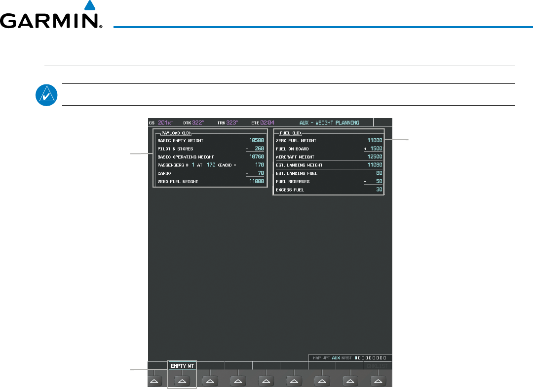
190-00928-04 Rev. A
Garmin G1000 Pilot’s Guide for the Beechcraft 200/B200 Series
273
FLIGHT MANAGEMENT
WEIGHT PLANNING
NOTE: All weight planning page data fields display data rounded to the nearest 10 pounds or 5 kilograms.
Figure 5-108 Weight Planning Page
A/C Payload Calculator
Basic Empty Weight Entry -
Pilot and Stores Weight Entry -
Basic Operating Weight Calculation -
Passenger(s) Weight Entry -
Cargo Weight Entry -
Zero Fuel Weight Calculation -
Fuel Weight Calculator
- Zero Fuel Weight Calculation
- Fuel on Board Entry
- Aircraft Weight Calculation
- Estimated Landing Weight Calculation
- Estimated Landing Fuel Calculation
- Fuel Reserve Entry
- Excess Fuel Calculation
Empty Weight Softkey
(selects Basic Empty
Weight)
Entering basic empty weight:
1) Select the EMPTY WT Softkey; or press the MENU Key, highlight ‘Set Basic Empty Weight’, and press the ENT
Key to select the ‘BASIC EMPTY WEIGHT’ field.
2) Turn the small FMS Knob to enter the basic empty weight.
3) Press the ENT Key to confirm the entry.
4) Press the FMS Knob to remove the flashing cursor.
Entering a pilot and stores weight:
1) Press the FMS Knob to activate the cursor and highlight the ‘PILOT AND STORES’ field.
2) Turn the small FMS Knob to enter the pilot and stores weight.
3) Press the ENT Key to confirm the entry.
4) Press the FMS Knob to remove the flashing cursor.
The basic operating weight is calculated by adding the basic empty weight and the pilot and stores weight.

Garmin G1000 Pilot’s Guide for the Beechcraft 200/B200 Series
190-00928-04 Rev. A274
FLIGHT MANAGEMENT
Entering the number of passengers:
1) Press the FMS Knob to activate the cursor and highlight the ‘PASSENGERS #’ field.
2) Turn the small FMS Knob to enter the number of passengers.
3) Press the ENT Key to confirm the entry.
4) Press the FMS Knob to remove the flashing cursor.
Entering the average passenger weight:
1) Press the FMS Knob to activate the cursor and highlight the passenger weight field.
2) Turn the small FMS Knob to enter the average passenger weight.
3) Press the ENT Key to confirm the entry.
4) Press the FMS Knob to remove the flashing cursor.
The total weight of passengers is calculated by multiplying the number of passengers by the average passenger
weight.
Entering the cargo weight:
1) Press the FMS Knob to activate the cursor and highlight the ‘CARGO’ field.
2) Turn the small FMS Knob to enter the cargo weight.
3) Press the ENT Key to confirm the entry.
4) Press the FMS Knob to remove the flashing cursor.
The ‘ZERO FUEL WEIGHT’ is calculated by adding the basic empty, pilot and stores, passenger, and cargo
weights.
Entering a fuel on board weight:
1) Press the FMS Knob to activate the cursor and highlight the ‘FUEL ON BOARD’ field.
2) Turn the small FMS Knob to enter the fuel on board.
3) Press the ENT Key to confirm the entry.
4) Press the FMS Knob to remove the flashing cursor.
Entering fuel reserve:
1) Press the FMS Knob to activate the cursor and highlight the ‘FUEL RESERVES’ field.
2) Turn the small FMS Knob to enter the fuel reserves amount.
3) Press the ENT Key to confirm the entry.
4) Press the FMS Knob to remove the flashing cursor

190-00928-04 Rev. A
Garmin G1000 Pilot’s Guide for the Beechcraft 200/B200 Series
275
FLIGHT MANAGEMENT
When the aircraft is in the air and a destination waypoint has been entered, the fuel calculations can be
completed.
• Estimated landing weight = zero fuel weight + estimated landing fuel weight.
• Estimated landing fuel weight = fuel on board weight - (fuel flow x ETE)
• Excess fuel weight = estimated landing fuel weight - fuel reserves weight
If the aircraft is on the ground or a destination waypoint has not been entered, the following fields display
invalid values consisting of six dashes:
• Estimated landing weight
• Estimated landing fuel weight
• Excess fuel weight
WEIGHT CAUTION AND WARNING CONDITIONS
If the zero fuel weight is greater than the maximum allowable zero fuel weight, then the zero fuel weight is
displayed in amber.
If the aircraft weight is greater than the maximum allowable takeoff weight, then the aircraft weight is displayed
in amber.
If the estimated landing weight is greater than the maximum allowable landing weight, then the estimated
landing weight is displayed in amber.
If the estimated landing fuel weight is positive, but less than or equal to the fuel reserves weight, the following
values are displayed in amber:
• Estimated fuel at landing weight
• Excess fuel weight
If the estimated landing fuel weight is zero or negative, then the following values are displayed in red:
• Estimated fuel at landing weight
• Excess fuel weight
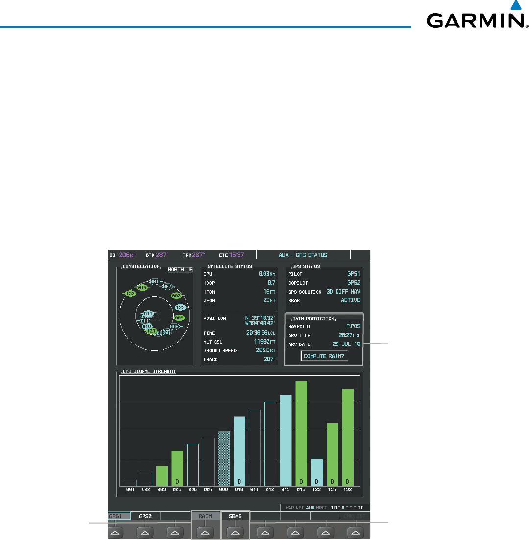
Garmin G1000 Pilot’s Guide for the Beechcraft 200/B200 Series
190-00928-04 Rev. A276
FLIGHT MANAGEMENT
5.10 RAIM PREDICTION
RAIM (Receiver Autonomous Integrity Monitoring) is a GPS receiver function that performs a consistency
check on all tracked satellites. RAIM ensures that the available satellite geometry allows the receiver to calculate
a position within a specified RAIM protection limit (2.0 nm for oceanic, 2.0 nm for enroute, 1.0 nm for terminal,
and 0.3 nm for non-precision approaches). During oceanic, enroute, and terminal phases of flight, RAIM is
available nearly 100% of the time. The RAIM prediction function also indicates whether RAIM is available at a
specified date and time. RAIM computations predict satellite coverage within ±15 min of the specified arrival
date and time. Because of the tighter protection limit on approaches, there may be times when RAIM is not
available. RAIM prediction must be initiated manually if there is concern over SBAS coverage at the destination
or some other reason that compromises navigation precision. If RAIM is not predicted to be available for the
final approach course, the approach does not become active. If RAIM is not available when crossing the FAF, the
missed approach procedure must be flown.
Figure 5-109 RAIM Prediction
SBAS Softkey
(displays SBAS Selection)
RAIM PREDICTION Box
- Prediction Waypoint
- Arrival Time
- Arrival Date
- RAIM Status
RAIM Softkey
(displays RAIM
PREDICTION)

190-00928-04 Rev. A
Garmin G1000 Pilot’s Guide for the Beechcraft 200/B200 Series
277
FLIGHT MANAGEMENT
Predicting RAIM availability at a selected waypoint:
1) Select the AUX-GPS Status Page.
2) Press the FMS Knob. The RAIM Prediction ‘WAYPOINT’ field is highlighted.
3) Turn the small FMS Knob to display the Waypoint Information Window. (Turning it clockwise displays a blank
Waypoint Information Window, turning it counter-clockwise displays the Waypoint Information Window
with a waypoint selection submenu allowing selection of active flight plan, nearest, recent, user, or airway
waypoints).
4) Enter the identifier, facility, or city name of the departure waypoint; or select a waypoint from the submenu of
waypoints and press the ENT Key to accept the waypoint entry.
5) Turn the FMS Knobs to enter an arrival time and press the ENT Key.
6) Turn the FMS Knobs to enter an arrival date and press the ENT Key.
7) Press the ENT Key with ‘COMPUTE RAIM?’ highlighted to begin the computation.
Predicting RAIM availability at the aircraft present position:
1) Select the AUX-GPS Status Page.
2) Press the FMS Knob. The RAIM Prediction ‘WAYPOINT’ field is highlighted.
3) Press the MENU Key, highlight ‘Set WPT to Present Position’, and press the ENT Key.
4) Press the ENT Key to accept the waypoint entry.
5) Turn the FMS Knobs to enter an arrival time and press the ENT Key.
6) Turn the FMS Knobs to enter an arrival date and press the ENT Key.
7) Press the ENT Key with ‘COMPUTE RAIM?’ highlighted to begin the computation.
Status of the RAIM computation for the selected waypoint, time, and date is displayed at the bottom of the
RAIM PREDICTION Box as follows:
• ‘COMPUTE RAIM?’ - RAIM has not been computed.
• ‘COMPUTING AVAILABILITY’ - RAIM calculation is in progress.
• ‘RAIM AVAILABLE’ - RAIM is predicted to be available.
• ‘RAIM NOT AVAILABLE’ - RAIM is predicted to be unavailable.
The Satellite Based Augmentation System (SBAS) provides increased navigation accuracy when available. SBAS
can be enabled or disabled manually on the GPS Status Page.
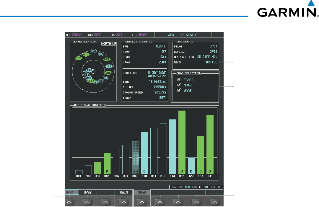
Garmin G1000 Pilot’s Guide for the Beechcraft 200/B200 Series
190-00928-04 Rev. A278
FLIGHT MANAGEMENT
Figure 5-110 SBAS Display - Active
SBAS Softkey
(displays SBAS Selection)
SBAS SELECTION Box
-
EGNOS Enable/Disable
-
MSAS Enable/Disable
-
WAAS Enable/Disable
RAIM Softkey
(displays RAIM
PREDICTION)
SBAS Status
Enabling/Disabling SBAS:
1) Select the AUX-GPS Status Page.
2) Press the SBAS Softkey.
3) Press the
FMS
Knob
, and turn the large FMS Knob to highlight ‘EGNOS’, ‘MSAS’ or ‘WAAS’.
4) Press the ENT Key to disable SBAS. Press the ENT Key again to enable SBAS.
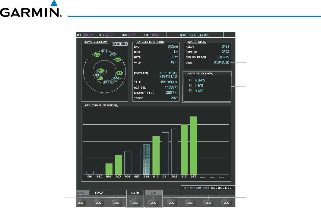
190-00928-04 Rev. A
Garmin G1000 Pilot’s Guide for the Beechcraft 200/B200 Series
279
FLIGHT MANAGEMENT
Figure 5-111 SBAS Display - Disabled
SBAS Softkey
(displays SBAS Selection)
SBAS SELECTION Box
-
EGNOS Enable/Disable
-
MSAS Enable/Disable
-
WAAS Enable/Disable
RAIM Softkey
(displays RAIM
PREDICTION)
SBAS Status
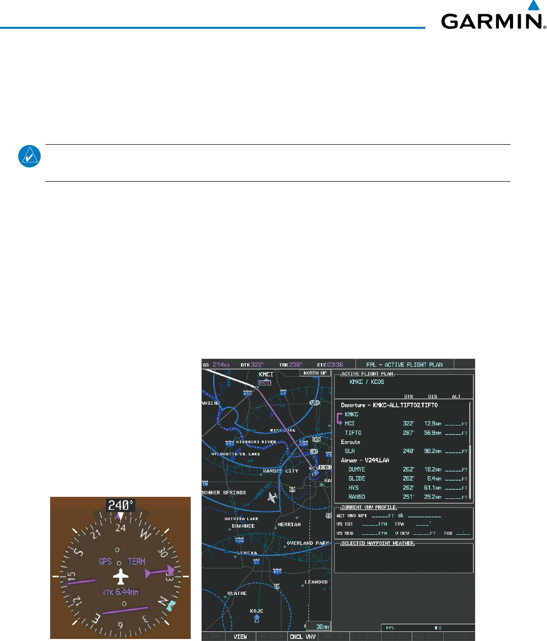
Garmin G1000 Pilot’s Guide for the Beechcraft 200/B200 Series
190-00928-04 Rev. A280
FLIGHT MANAGEMENT
5.11 NAVIGATING A FLIGHT PLAN
The following discussion is an example of navigating a flight plan with the SBAS capable GPS system while the
G1000 provides vertical guidance through descents. A lateral flight plan (LNAV) would be navigated in much the
same way, but would not include vertical guidance when the final approach course is active.
NOTE: The following example flight plan is for instructional purposes only. All database information depicted
should be considered not current.
The example is a flight plan from KMKC to KCOS filed using the TIFTO2 departure, various Victor Airways,
and the DBRY1 arrival with the transition at TBE. The flight plan includes an enroute altitude of 12,000 feet, an
RNAV LPV (WAAS) approach selected for runway 35R, and a missed approach executed at the Missed Approach
Point (MAP). A few enroute changes are demonstrated.
1) Prior to departure, the TIFTO2 departure, the airways, and the DBRY1 arrival at KCOS are loaded. See the
Procedures section for loading departures and arrivals. Note the magenta arrow in Figure 5-112 indicating the
active departure leg.
After takeoff, ATC assigns a heading of 240º.
2) Figure 5-112 shows the aircraft on the assigned heading of 240º. ‘TERM’ (Terminal) is the current CDI flight
phase displayed on the HSI indicating 1.0 nm CDI scaling.
Figure 5-112 Assigned Heading of 240º
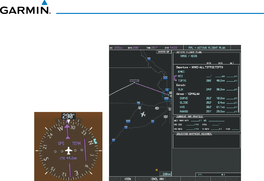
190-00928-04 Rev. A
Garmin G1000 Pilot’s Guide for the Beechcraft 200/B200 Series
281
FLIGHT MANAGEMENT
3) ATC now assigns routing to join V4. A heading of 290º is assigned to intercept V4. The aircraft turns to heading
290° as seen in Figure 5-113.
Figure 5-113 Assigned Heading of 290º
4) Enter V4 into the flight plan.
a) Press the FMS Knob to activate the cursor.
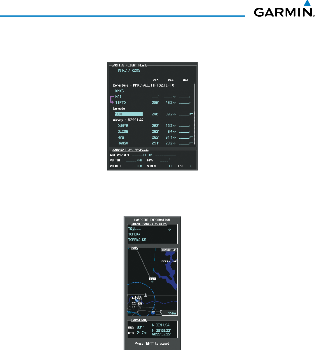
Garmin G1000 Pilot’s Guide for the Beechcraft 200/B200 Series
190-00928-04 Rev. A282
FLIGHT MANAGEMENT
b) The desired entry point for V4 (TOP) must be entered. Turn the large FMS Knob to highlight the desired flight
plan insertion point (SLN) as shown in Figure 5-114. When the V4 entry point (TOP) is inserted, it is placed
immediately above the highlighted waypoint (SLN).
Figure 5-114 Begin Adding V4 to the Flight Plan
c) Turn the small FMS Knob to display the Waypoint Information Window. Enter the desired entry point for V4,
Topeka VOR (TOP), as shown in Figure 5-115.
Figure 5-115 Entering V4 Entry Point
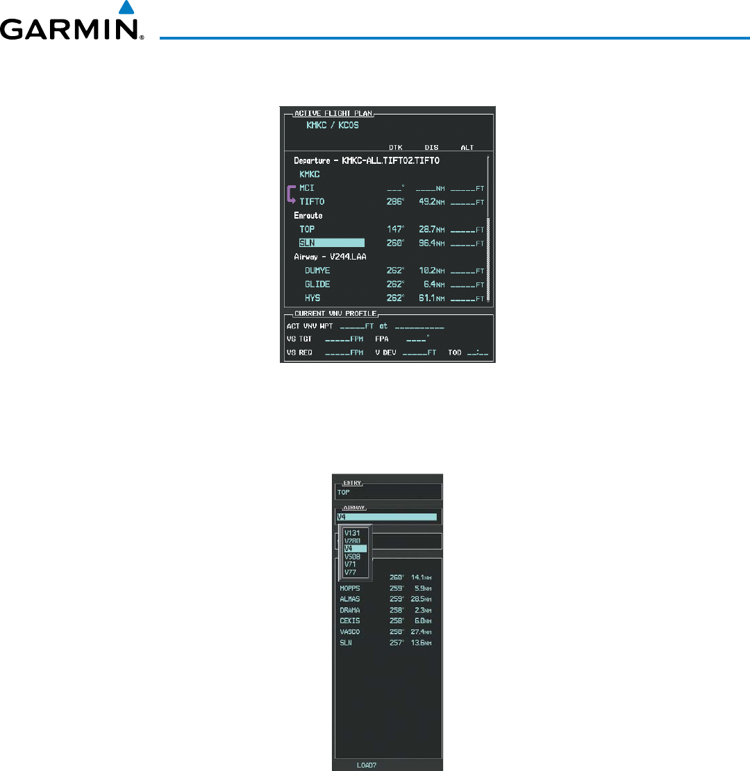
190-00928-04 Rev. A
Garmin G1000 Pilot’s Guide for the Beechcraft 200/B200 Series
283
FLIGHT MANAGEMENT
d) Press the ENT Key. TOP is inserted into the flight plan as in Figure 5-116.
Figure 5-116 TOP Inserted into the Flight Plan
e) With SLN still highlighted as in Figure 5-116, turn the small FMS Knob clockwise. The Waypoint Information
Page is displayed and the LD AIRWY Softkey is now available.
f) Select the LD AIRWY Softkey to display the list of available airways for TOP as seen in Figure 5-117.
Figure 5-117 List of Available Airways for TOP
g) Turn either FMS Knob to highlight V4 in the list as seen in Figure 5-117.
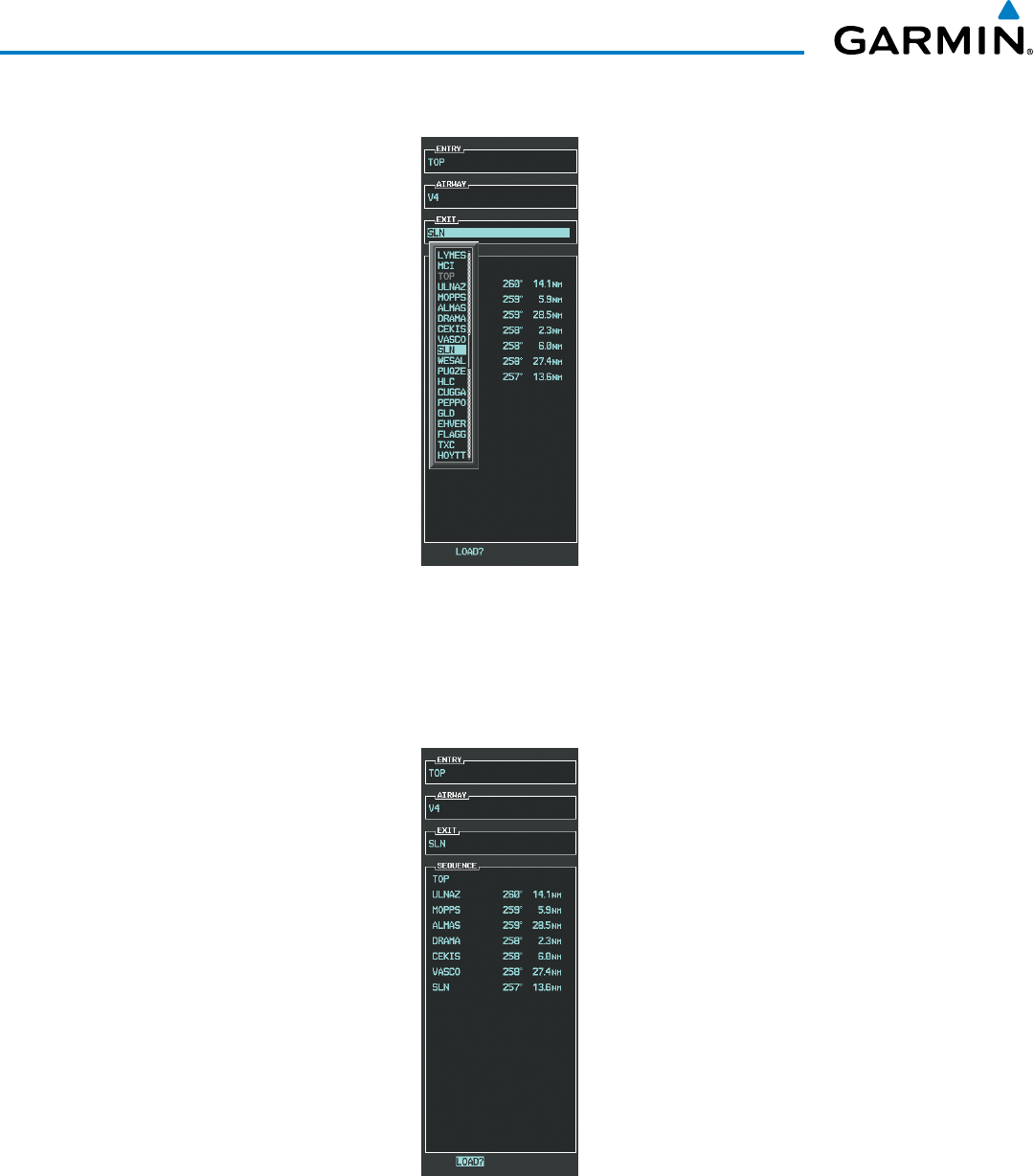
Garmin G1000 Pilot’s Guide for the Beechcraft 200/B200 Series
190-00928-04 Rev. A284
FLIGHT MANAGEMENT
h) Press the ENT Key. The list of available exits for V4 is now displayed as in Figure 5-118.
Figure 5-118 List of Available Exits for V4
i) If necessary, turn either FMS Knob to select the desired exit. In this case Salina VOR (SLN) is selected as in
Figure 5-118.
j) Press the ENT Key. The selected airway and exit are displayed, and the prompt “LOAD?” highlighted as in
Figure 5-119.
Figure 5-119 Ready to Load V4
k) Press the ENT Key.
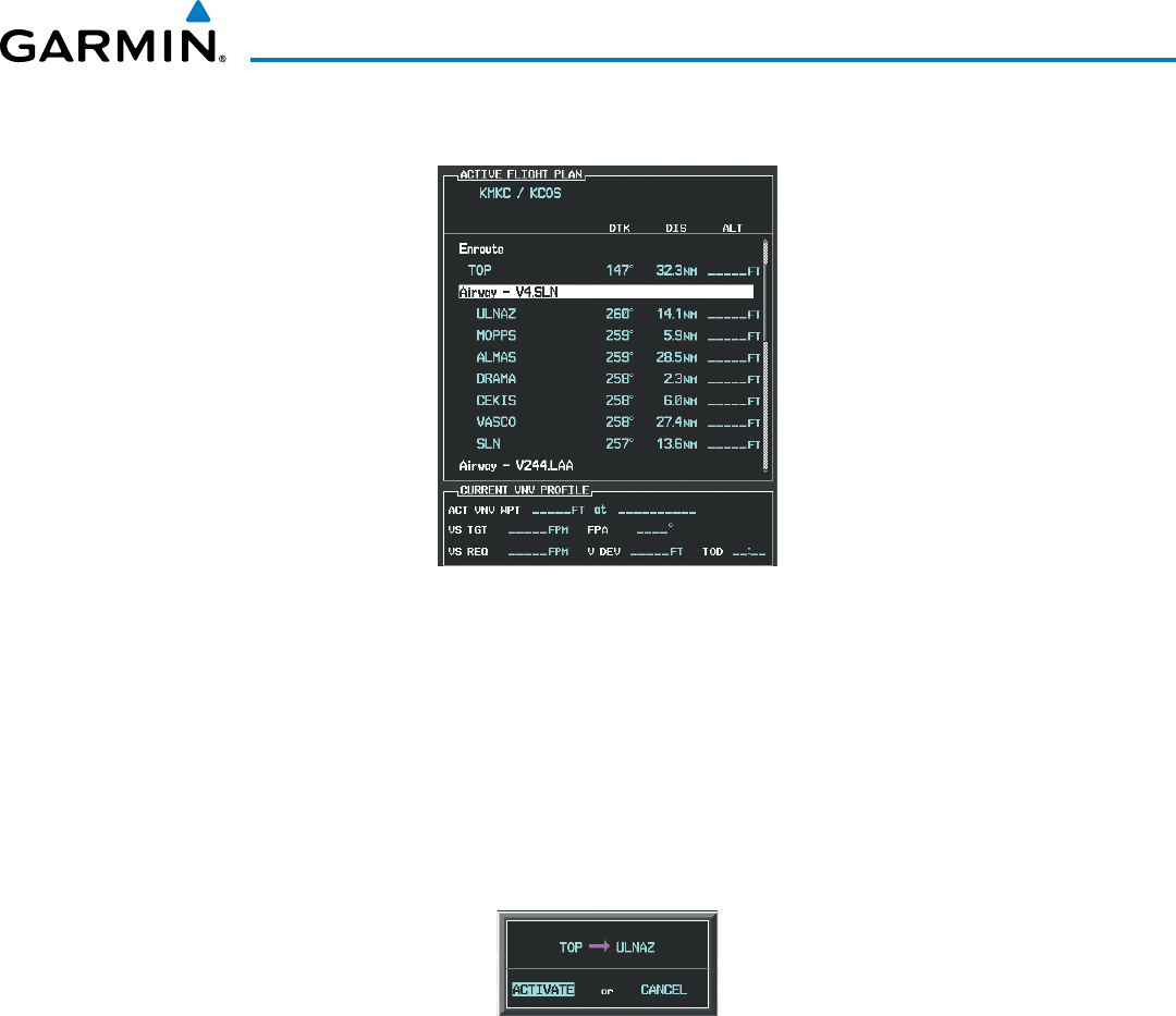
190-00928-04 Rev. A
Garmin G1000 Pilot’s Guide for the Beechcraft 200/B200 Series
285
FLIGHT MANAGEMENT
l) V4 is now loaded into the flight plan as shown in Figure 5-120.
Figure 5-120 V4 is Loaded in the Flight Plan
5) Making V4 the active leg of the flight plan.
a) Press the FMS Knob to activate the cursor.
b) Turn the large FMS Knob to highlight ULNAZ. The TO waypoint of the leg is selected in order to activate the
leg.
c) Select the ACT LEG Softkey. The confirmation window is now displayed as in Figure 5-121. Note the TOP to
ULNAZ leg is actually part of V4.
Figure 5-121 Comfirm Active Leg
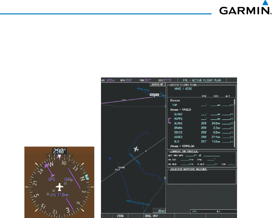
Garmin G1000 Pilot’s Guide for the Beechcraft 200/B200 Series
190-00928-04 Rev. A286
FLIGHT MANAGEMENT
d) Verify the displayed leg is the desired leg and press the ENT Key. Note in Figure 5-122, the magenta arrow in
the flight plan window and magenta line on the map indicating V4 is now the active flight plan leg. Note the
phase of flight remained in Terminal (TERM) mode up to this point because a departure leg was active. Since a
leg after the departure is now active, the current CDI flight phase is ENR (Enroute) and CDI scaling has changed
to 2.0 nm.
Figure 5-122 V4 Now Active Leg
6) The aircraft continues on heading 290º. When crosstrack distance is less than 2.0 nm, the XTK disappears from
the HSI and the CDI is positioned on the last dot indicating a 2.0 nm distance from the centerline of the next
course.
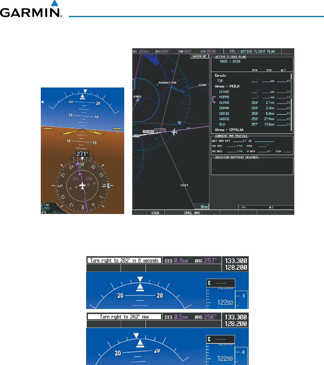
190-00928-04 Rev. A
Garmin G1000 Pilot’s Guide for the Beechcraft 200/B200 Series
287
FLIGHT MANAGEMENT
7) As the CDI approaches center, the aircraft turns onto the active leg as seen in Figure 5-123.
Figure 5-123 Turn on to Active Leg
8) At SLN, Victor Airway 244 (V244) is intercepted. Turn prompts are displayed in the PFD Navigation Status Box
as seen in Figure 5-124.
Figure 5-124 Turn to Intercept V244
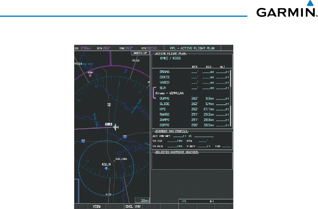
Garmin G1000 Pilot’s Guide for the Beechcraft 200/B200 Series
190-00928-04 Rev. A288
FLIGHT MANAGEMENT
9) As seen in Figure 5-125, V244 is now the active flight plan leg.
Figure 5-125 V244 Now Active Leg
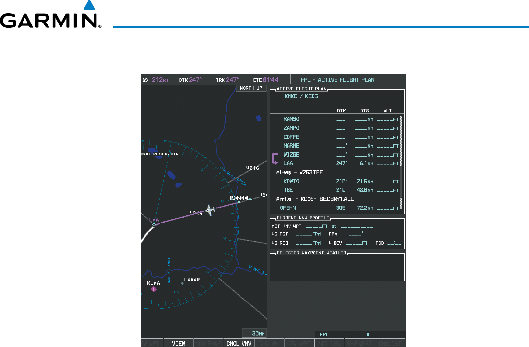
190-00928-04 Rev. A
Garmin G1000 Pilot’s Guide for the Beechcraft 200/B200 Series
289
FLIGHT MANAGEMENT
10) At Lamar VOR (LAA) V263 is intercepted. See Figure 5-126.
Figure 5-126 WIZGE to LAA Leg Active
11) ATC grants clearance to proceed direct to the OPSHN intersection to begin the arrival procedure. ATC advises
to expect an altitude of 10,000 feet at OPSHN.
a) Press the FMS Knob to activate the cursor.
b) Turn the large FMS Knob to select OPSHN in the flight plan list.
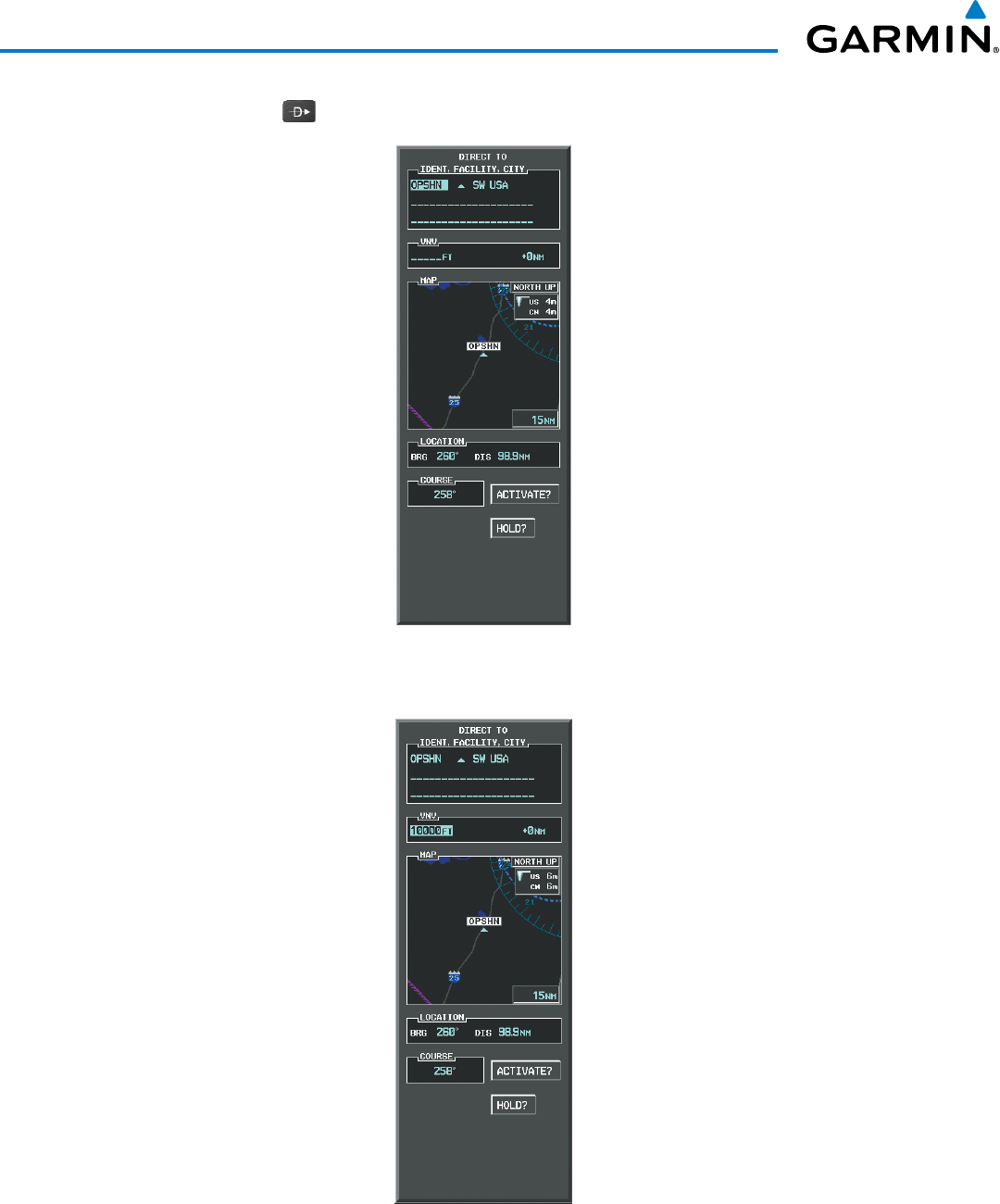
Garmin G1000 Pilot’s Guide for the Beechcraft 200/B200 Series
190-00928-04 Rev. A290
FLIGHT MANAGEMENT
c) Press the
Direct-to
( )
Key. The Direct-to Window is now displayed as shown in Figure 5-127.
Figure 5-127 Direct To OPSHN
d) Turn the large FMS Knob to place the cursor in the VNV altitude field as shown in Figure 5-128.
Figure 5-128 Enter VNV Altitude
e) An altitude of 10,000 feet is entered as requested by ATC.
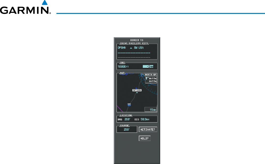
190-00928-04 Rev. A
Garmin G1000 Pilot’s Guide for the Beechcraft 200/B200 Series
291
FLIGHT MANAGEMENT
f) Press the ENT Key. The cursor is now displayed in the VNV offset field as shown in Figure 5-129.
Figure 5-129 Enter VNV Offset Distance
g) Enter the offset, or distance from the waypoint at which to reach the selected altitude. In this case, three miles
prior to OPSHN is entered. In other words, the G1000 gives vertical guidance so the aircraft arrives at an
altitude of 10,000 feet three miles prior to OPSHN.
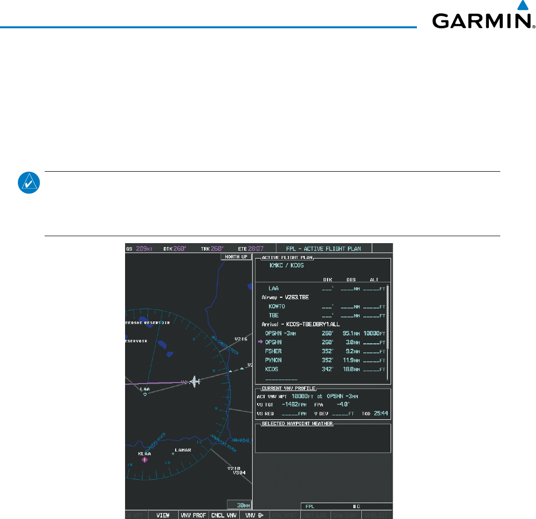
Garmin G1000 Pilot’s Guide for the Beechcraft 200/B200 Series
190-00928-04 Rev. A292
FLIGHT MANAGEMENT
h) Press the ENT Key twice to activate the direct-to. Note, in Figure 5-130, the magenta arrow indicating the
direct-to OPSHN after the offset waypoint for OPSHN. The preceding offset waypoint indicates the offset
distance and altitude that were previously entered. The remaining waypoints in the loaded arrival procedure
have no database specified altitudes, therefore, dashes are displayed. Keep the CDI centered and maintain a
track along the magenta line to OPSHN.
Note the Direct-to waypoint is within the loaded arrival procedure, therefore, phase of flight scaling for the CDI
changes to Terminal Mode and is annunciated by displaying ‘TERM’ on the HSI.
NOTE: If the loaded arrival procedure has waypoints with altitude constraints retrieved from the database
to be used as is, the altitude must be manually accepted by placing the cursor over the desired altitude,
then pressing the ENT Key. The altitude is now displayed as light blue meaning it is used by the system to
determine vertical speed and deviation guidance.
Figure 5-130 Direct-to Active
12) The aircraft is proceeding to OPSHN. The expected approach is the RNAV LPV approach to runway 35R, so it is
selected.
a) Press the
PROC
Key to display the Procedures Window.
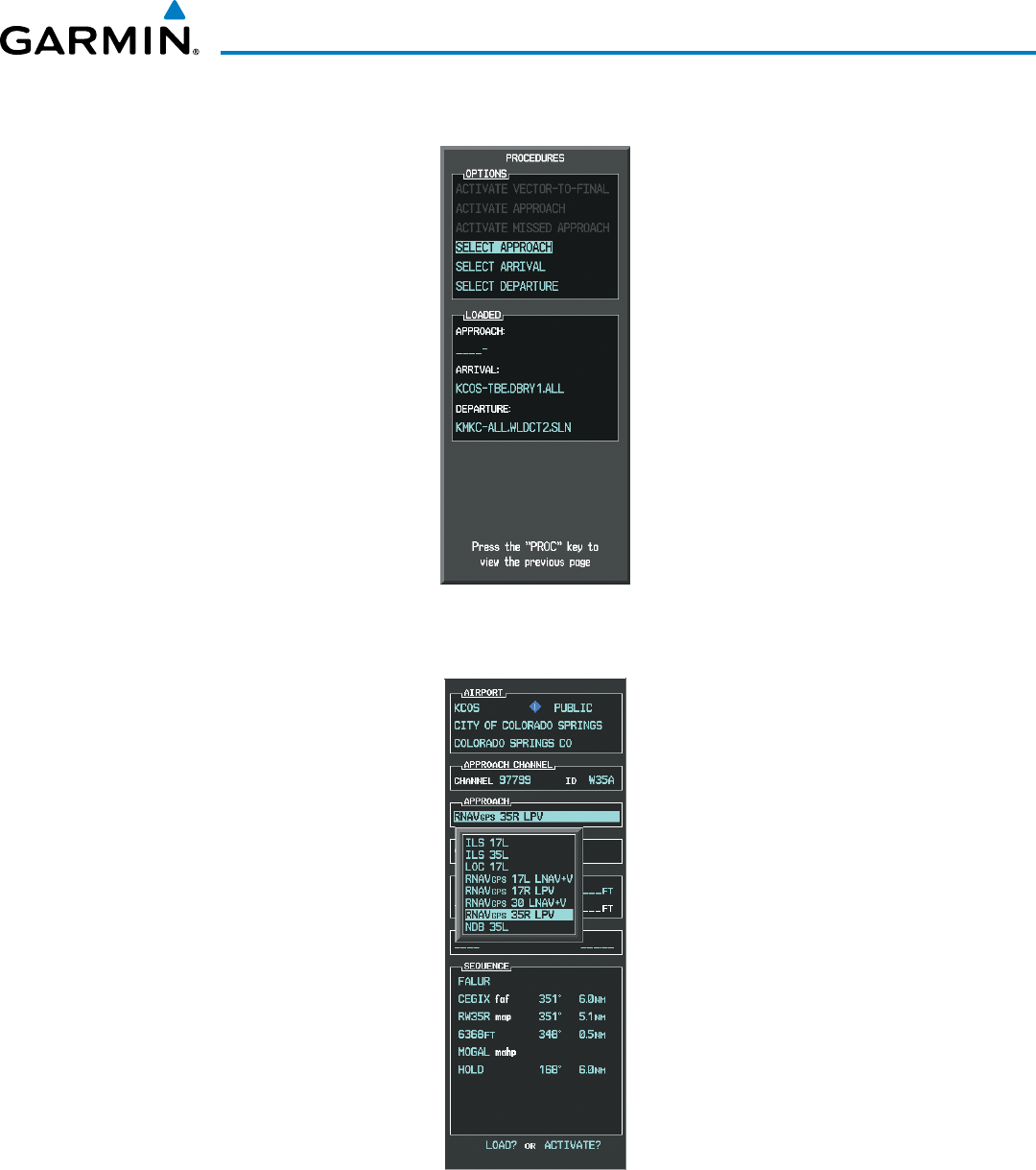
190-00928-04 Rev. A
Garmin G1000 Pilot’s Guide for the Beechcraft 200/B200 Series
293
FLIGHT MANAGEMENT
b) ‘SELECT APPROACH’ should be highlighted as shown in Figure 5-131.
Figure 5-131 Procedures Window
c) Press the ENT Key. A list of available approaches for the destination airport is displayed as in Figure 5-132.
Figure 5-132 List of Available Approaches
d) Turn either
FMS
Knob to select the RNAV LPV approach for 35R as shown in Figure 5-132.
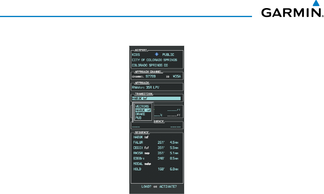
Garmin G1000 Pilot’s Guide for the Beechcraft 200/B200 Series
190-00928-04 Rev. A294
FLIGHT MANAGEMENT
e) Press the ENT Key. A list of available transitions for the selected approach is displayed as in Figure 5-133.
Figure 5-133 List of Available Transitions
f) Turn either FMS Knob to select the desired transition. In this case, the Initial Approach Fix (IAF) at HABUK is
used.
g) Press the ENT Key.
h) Barometric Minimums
To set ‘MINIMUMS’, turn the small FMS Knob to select ‘BARO’, and press the ENT Key. Turn the small
FMS Knob to select the altitude, and press the ENT Key.
Or:
To skip setting minimums, press the ENT Key.
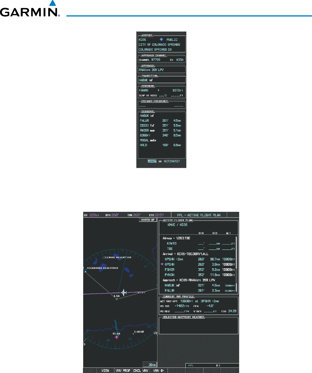
190-00928-04 Rev. A
Garmin G1000 Pilot’s Guide for the Beechcraft 200/B200 Series
295
FLIGHT MANAGEMENT
Figure 5-134 Barometric Minimums Set
i) With ‘LOAD?’ highlighted, again press the ENT Key. The selected approach is added to the flight plan as seen
in Figure 5-135.
Figure 5-135 Loaded Approach
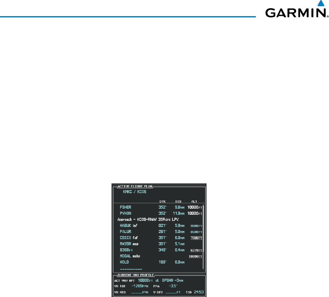
Garmin G1000 Pilot’s Guide for the Beechcraft 200/B200 Series
190-00928-04 Rev. A296
FLIGHT MANAGEMENT
13) Note the altitude constraints associated with each of the approach waypoints as seen in Figure 5-136. These
altitudes are loaded from the database and are displayed as light blue text, indicating these values are
“designated” for use in computing vertical deviation guidance.
Note: To no longer use the displayed altitude for calculating vertical deviation guidance, perform the
following:
a) Press the FMS Knob to activate the cursor.
b) Turn the small FMS Knob to highlight the desired altitude.
c) Press the CLR Key.
d) Press the FMS Knob to deactivate the cursor.
After making the altitude “non-designated”, it is displayed as white text.
Altitude constraint values associated with the Final Approach Fix (FAF) and waypoints beyond the FAF cannot be
designated for vertical guidance. These altitude values are always displayed as white text, as in Figure 5-136.
Vertical guidance from the FAF and on to the Missed Approach Point (MAP) is given using the SBAS GPS altitude
source, therefore, the displayed altitude values are for reference only.
Figure 5-136 Vertical Guidance is Active to the FAF
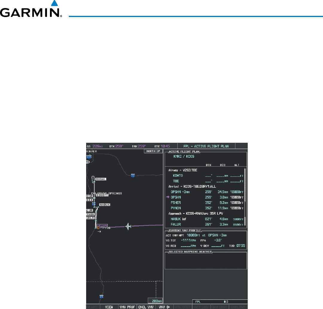
190-00928-04 Rev. A
Garmin G1000 Pilot’s Guide for the Beechcraft 200/B200 Series
297
FLIGHT MANAGEMENT
14) As the aircraft approaches OPSHN, it may be desirable to adjust the speed, or steepness of the upcoming
descent. The default Flight Path Angle (FPA) is -3.5 degrees and a required vertical speed is computed to
maintain the -3.5 FPA. To change the vertical flight path, perform the following steps.
a) Select the VNV PROF Softkey to place the cursor in the target vertical speed field (VS TGT) as shown in Figure
5-137.
b) At this point, the descent vertical speed can be selected, or the FPA can be selected. Turn the large FMS Knob
to select the desired selection field, then turn the small FMS Knob to enter the desired value.
Note the information now displayed in the ‘CURRENT VNV PROFILE’ box. Also, note the offset waypoint (orange
box) and gray circle are now displayed on the map. The gray circle marks the Top of Descent (TOD). In this
example, vertical guidance is provided at the TOD that results in a -3.0 degree FPA descent to an altitude of
10,000 feet upon reaching the offset waypoint.
Figure 5-137 Adjusting the Descent
c) Press the ENT Key.
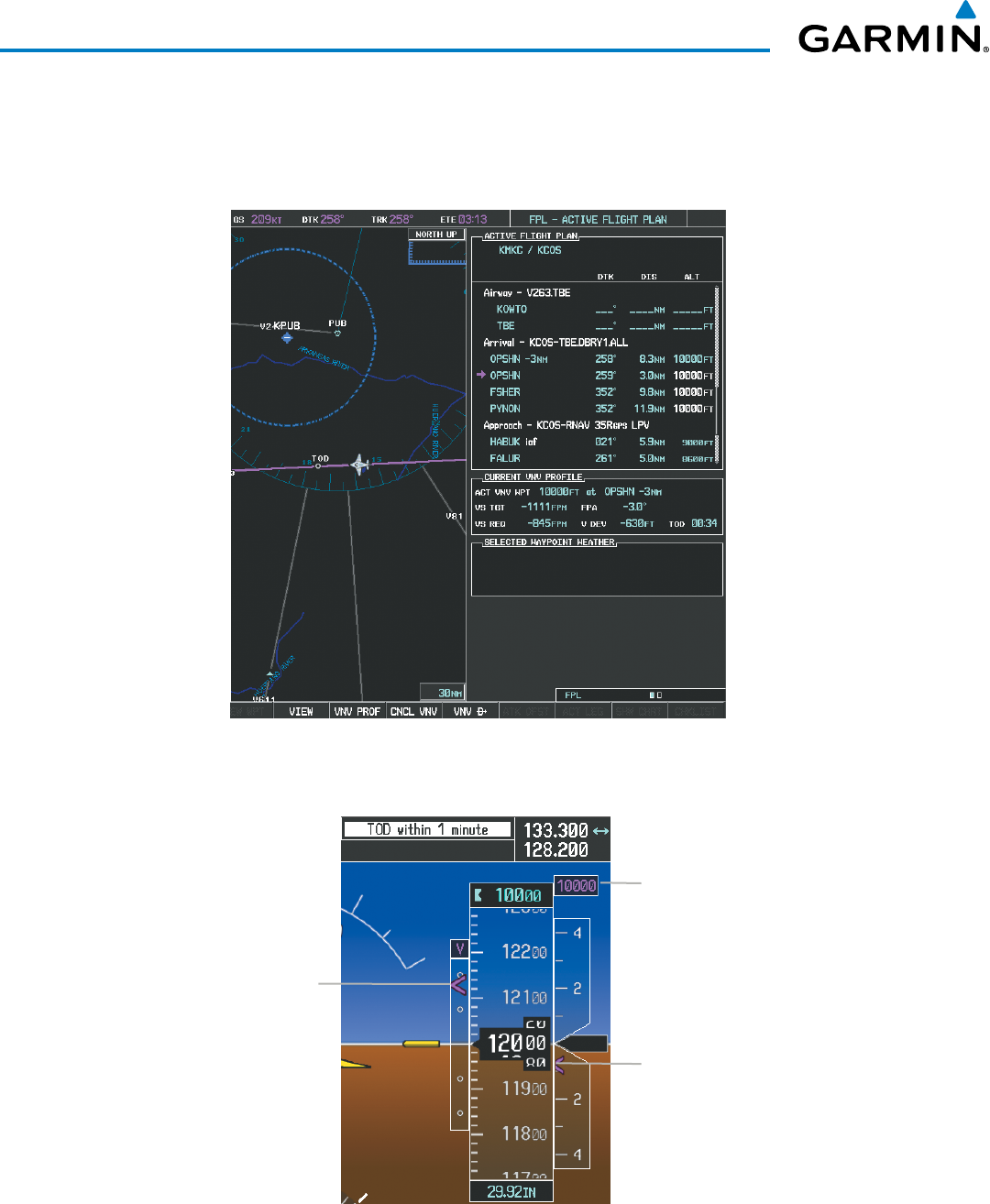
Garmin G1000 Pilot’s Guide for the Beechcraft 200/B200 Series
190-00928-04 Rev. A298
FLIGHT MANAGEMENT
15) As seen in Figure 5-138, the aircraft is approaching TOD. Note the target vertical speed required to reach the
selected altitude. The Vertical Deviation Indicator (VDI) and the Required Vertical Speed Indicator (RVSI) are
now displayed on the PFD as shown in Figure 5-139. When the aircraft is within one minute of the TOD, it is
annunciated as shown in Figure 5-139, and an aural alert ‘Vertical track’ will be heard.
Figure 5-138 Approaching Top of Descent (TOD)
Figure 5-139 VDI & RVSI Upon Reaching Top of Descent (TOD)
Required Vertical
Speed Indicator
(RVSI)
Vertical Deviation
Indicator (VDI)
Target Altitude
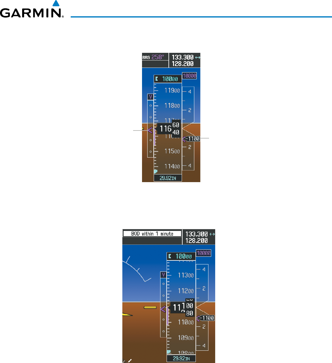
190-00928-04 Rev. A
Garmin G1000 Pilot’s Guide for the Beechcraft 200/B200 Series
299
FLIGHT MANAGEMENT
16) Upon reaching TOD, a descent vertical speed is established by placing the VSI pointer in line with the RVSI as
shown in Figure 5-140.
Figure 5-140 VDI & RVSI Showing Correctly Established Descent
Align Actual Vertical Speed
with
Required Vertical Speed
Keep Vertical Deviation
Indicator Centered
17) When the aircraft is one minute from the bottom of descent (BOD) it is annunciated as shown in Figure 5-141.
Upon reaching the offset waypoint for OPSHN, the aircraft is at 10,000 feet.
Figure 5-141 Approaching Bottom of Descent (BOD) at OPSHN Offset Waypoint
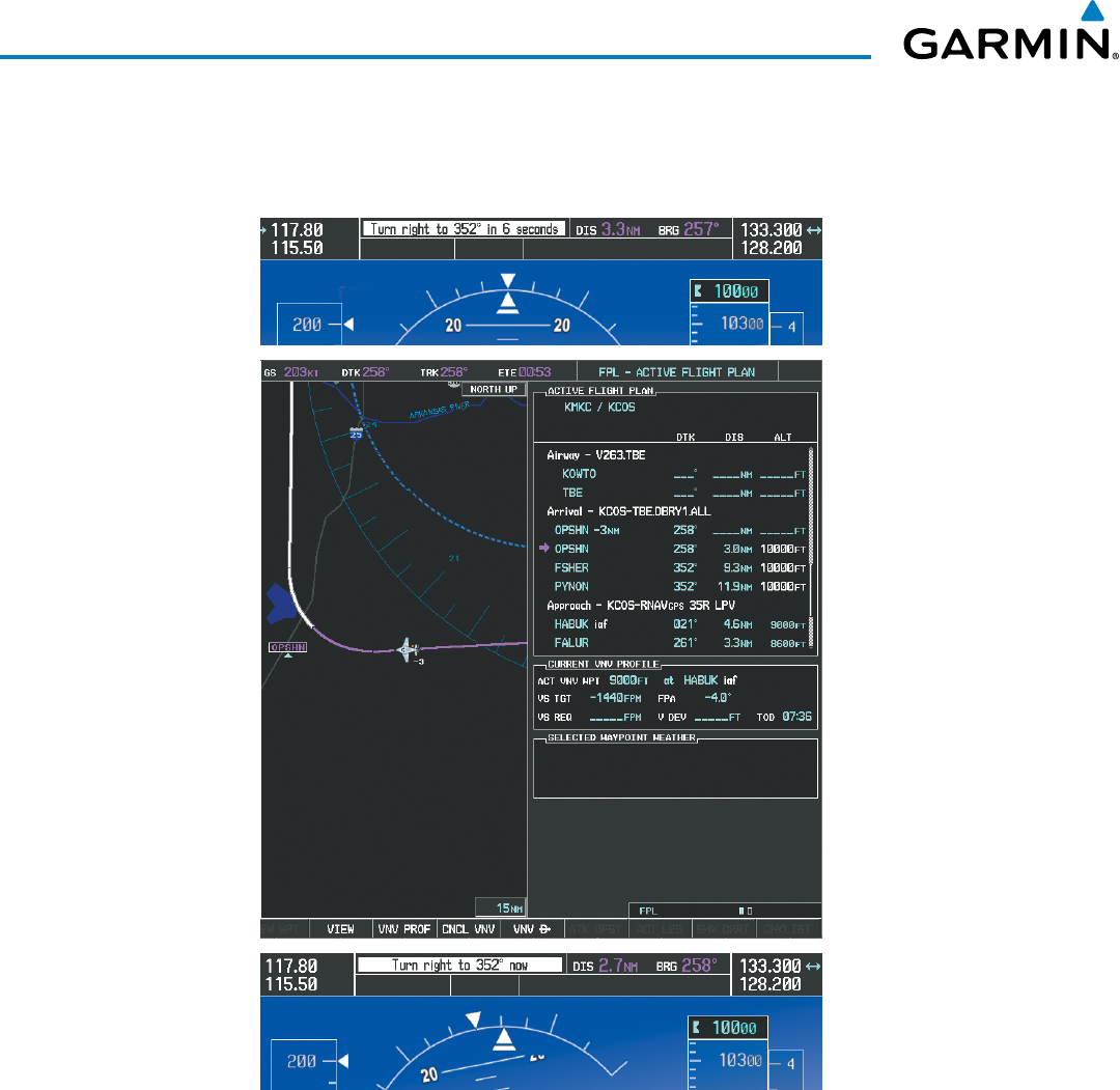
Garmin G1000 Pilot’s Guide for the Beechcraft 200/B200 Series
190-00928-04 Rev. A300
FLIGHT MANAGEMENT
18) The aircraft is approaching OPSHN. The upcoming turn and next heading are annunciated at the top left of the
PFD as seen in Figure 5-142. Initiate the turn and maneuver the aircraft on a track through the turn radius to
intercept the magenta line for the OPSHN to FSHER leg and center the CDI.
Figure 5-142 Turn to intercept OPSHN to FSHER Leg
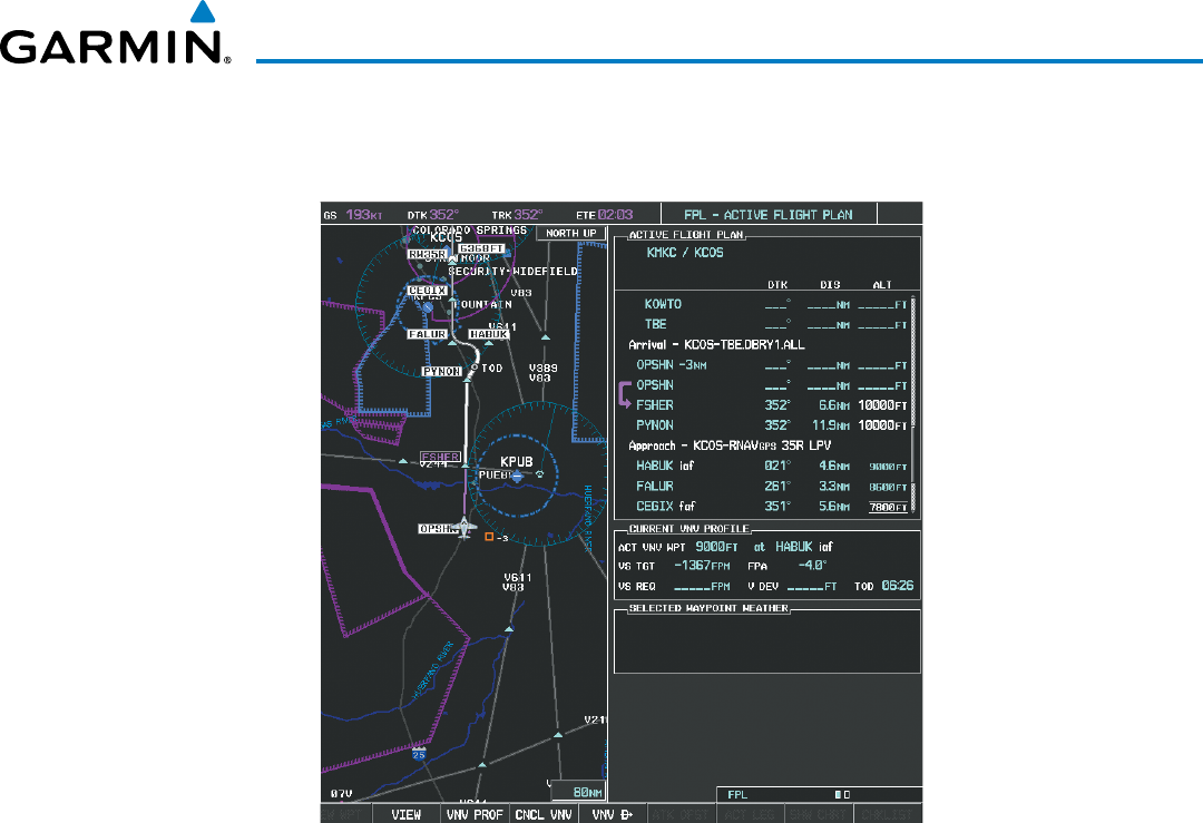
190-00928-04 Rev. A
Garmin G1000 Pilot’s Guide for the Beechcraft 200/B200 Series
301
FLIGHT MANAGEMENT
19) After passing OPSHN, the next leg of the arrival turns magenta as shown in Figure 5-143. The magenta arrow
in the flight plan list now indicates the OPSHN to FSHER leg of the arrival procedure is now active.
Figure 5-143 Tracking the OPSHN to FSHER Leg
20) The flight continues through the arrival procedure to PYNON (see Figure 5-144). At a point 31 nm from the
destination airport, the phase of flight scaling for the CDI changes to Terminal Mode and is annunciated by
displaying ‘TERM’ on the HSI.
A descent to HABUK is in the next leg. Note the TOD point on the map. Annunciations for the upcoming turn
and descent, as well as the VDI and RVSI, appear on the PFD as the flight progresses.
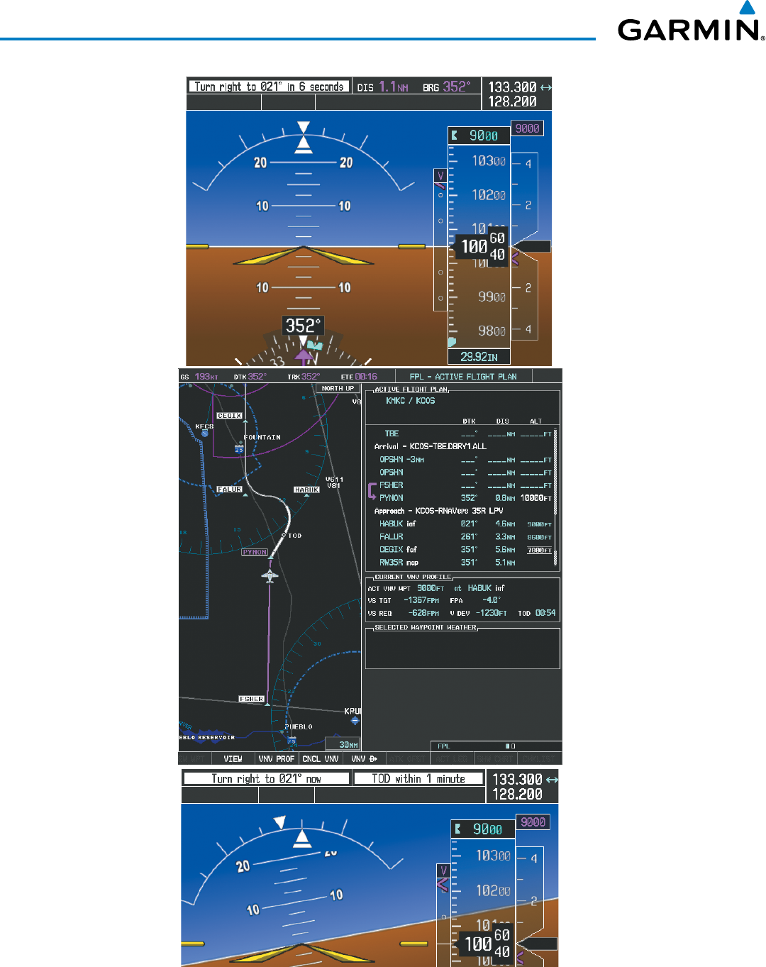
Garmin G1000 Pilot’s Guide for the Beechcraft 200/B200 Series
190-00928-04 Rev. A302
FLIGHT MANAGEMENT
Figure 5-144 Approaching PYNON
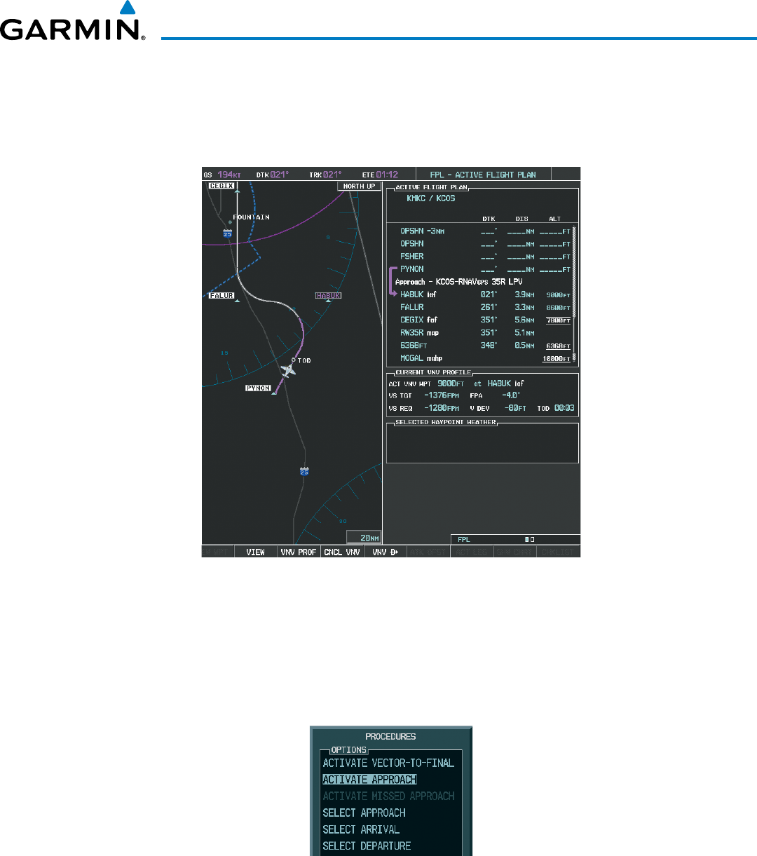
190-00928-04 Rev. A
Garmin G1000 Pilot’s Guide for the Beechcraft 200/B200 Series
303
FLIGHT MANAGEMENT
21) Upon passing PYNON the approach procedure automatically becomes active. The approach may be activated
at any point to proceed directly to the IAF. In this example, the aircraft has progressed through the final
waypoint of the arrival and the flight plan has automatically sequenced to the IAF as the active leg, activating
the approach procedure (see Figure 5-145).
Figure 5-145 Approach is Now Active
Note: To manually activate the approach procedure, perform the following steps:
a) Press the
PROC
Key.
b) Turn the large
FMS
Knob to highlight ‘ACTIVATE APPROACH’ as shown in Figure 5-146.
c) Press the
ENT
Key to activate the approach.
Figure 5-146 Manually Activate Approach
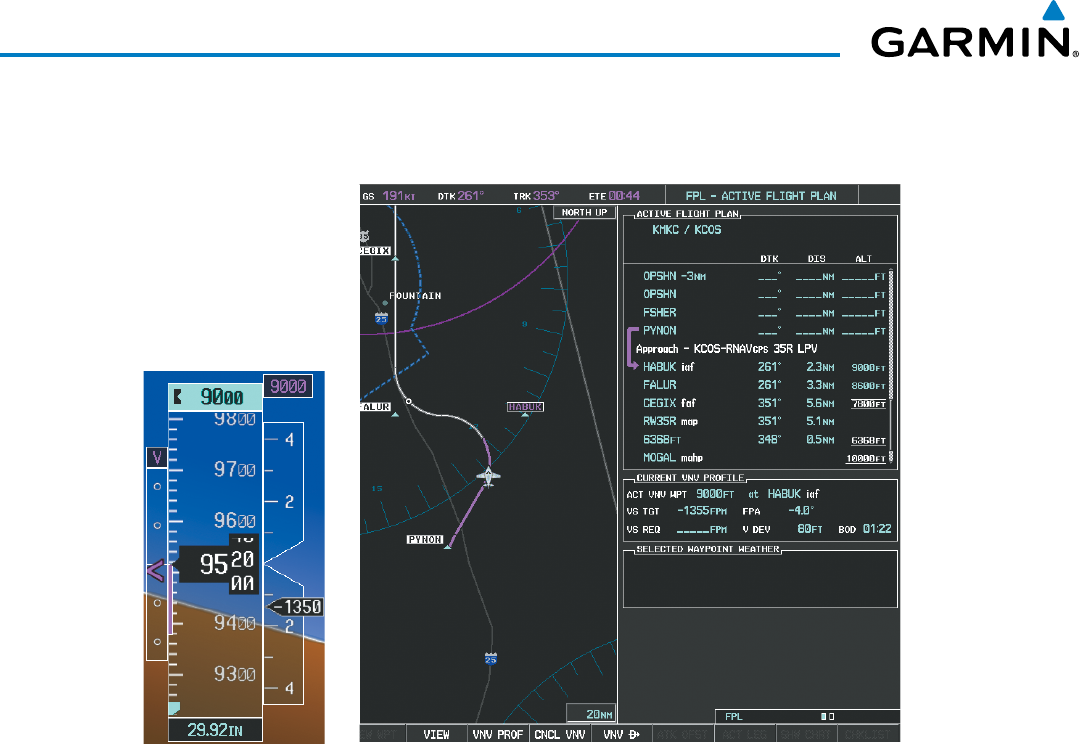
Garmin G1000 Pilot’s Guide for the Beechcraft 200/B200 Series
190-00928-04 Rev. A304
FLIGHT MANAGEMENT
22) The IAF is the next waypoint. At the TOD, establish a descent vertical speed as previously discussed in Step 16.
The aircraft altitude is 9,000 feet upon reaching HABUK.
Figure 5-147 Descending Turn to the Initial Approach Fix (IAF)
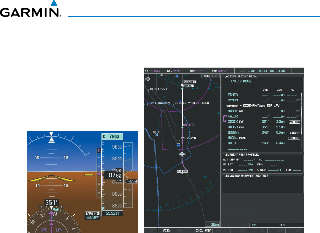
190-00928-04 Rev. A
Garmin G1000 Pilot’s Guide for the Beechcraft 200/B200 Series
305
FLIGHT MANAGEMENT
23) After crossing FALUR the next waypoint is the FAF. The flight phase changes to LPV on the HSI indicating the
current phase of flight is in Approach Mode and the approach service level is LPV. CDI scaling changes accordingly
and is used much like a localizer when flying an ILS approach. The RVSI is no longer displayed and the VDI
changes to the Glidepath Indicator (as shown in Figure 5-148) when the final approach course becomes active.
Figure 5-148 Descending to the FAF
The descent continues through the FAF (CEGIX) using the Glidepath Indicator, as one would use a glideslope
indicator, to obtain an altitude “AT” 7,800 feet at the FAF. Note the altitude restriction lines over and under (At)
the altitude in the ‘ALT’ field in Figure 5-148.
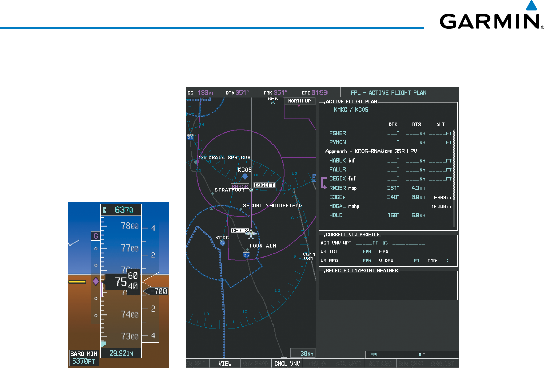
Garmin G1000 Pilot’s Guide for the Beechcraft 200/B200 Series
190-00928-04 Rev. A306
FLIGHT MANAGEMENT
24) After crossing CEGIX, the aircraft continues following the glidepath to maintain the descent to “AT or ABOVE”
6,370 feet at the Missed Approach Point (MAP) (RW35R) as seen in Figure 5-149.
Figure 5-149 Descending to the Missed Approach Point
In this missed approach procedure, the altitude immediately following the MAP (in this case ‘6368ft’) is not part
of the published procedure. It is simply a Course to Altitude (CA) leg which guides the aircraft along the runway
centerline until the altitude required to safely make the first turn toward the MAHP is exceeded. This altitude
is provided by Jeppesen, and may be below, equal to, or above the published minimums for this approach. In
this case, if the aircraft altitude is below the specified altitude (6,368 feet) after crossing the MAP, a direct-to
is established to provide a course on runway heading until an altitude of 6,368 feet is reached. After reaching
6,368 feet, a direct-to is established to the published MAHP (in this case MOGAL). If the aircraft altitude is
above the specified altitude after crossing the MAP, a direct-to is established to the published fix (MOGAL) to
begin the missed approach procedure.
In some missed approach procedures this Course to Altitude leg may be part of the published procedure. For
example, a procedure may dictate a climb to 5,500 feet, then turn left and proceed to the Missed Approach Hold
Point (MAHP). In this case, the altitude would appear in the list of waypoints as ‘5500ft’. Again, if the aircraft
altitude is lower than the prescribed altitude, a direct-to is established on a Course to Altitude leg when the
missed approach procedure is activated.
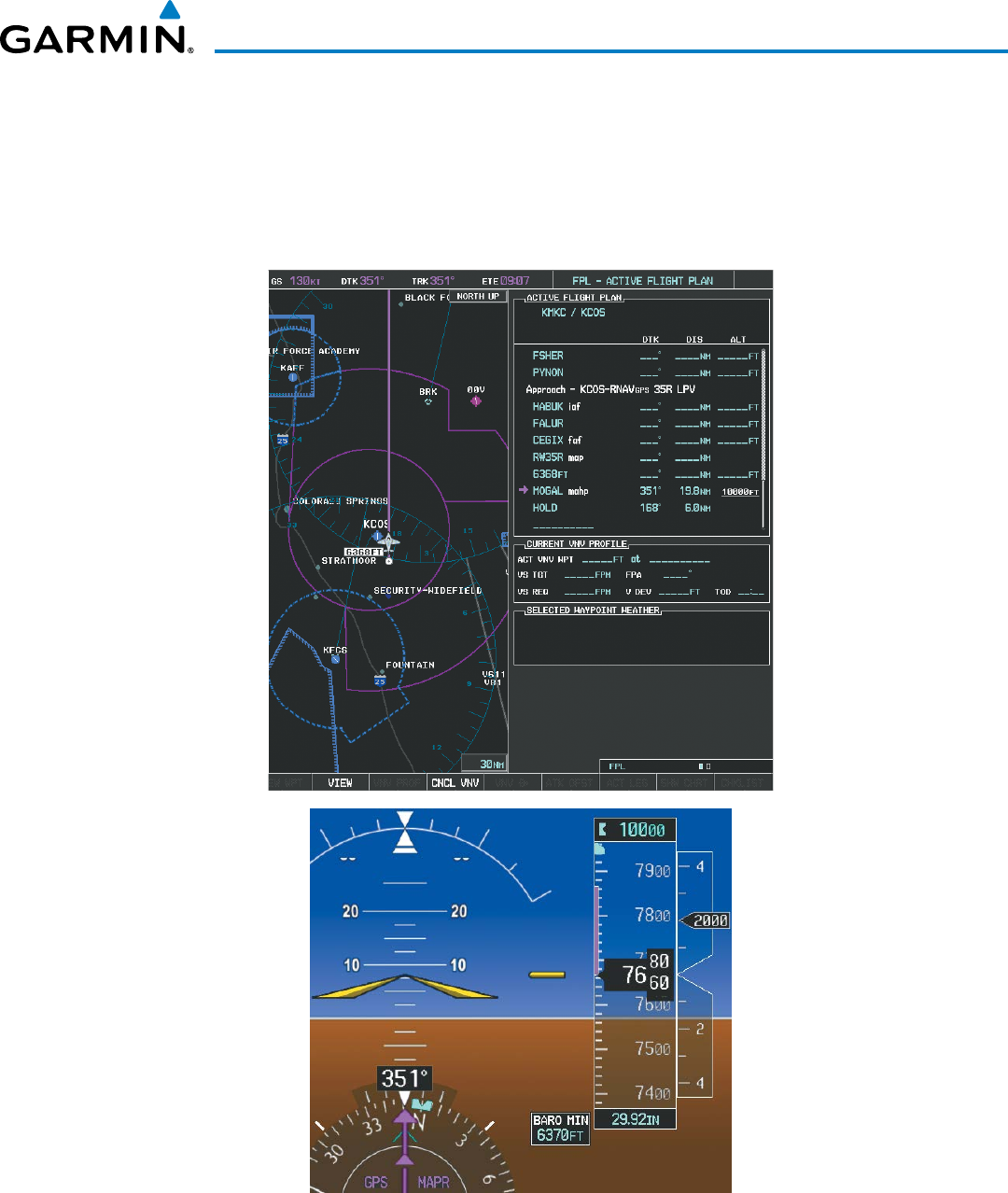
190-00928-04 Rev. A
Garmin G1000 Pilot’s Guide for the Beechcraft 200/B200 Series
307
FLIGHT MANAGEMENT
25) Upon reaching the MAP, it is decided to execute a missed approach. Automatic waypoint sequencing is
suspended past the MAP. Select the
SUSP
Softkey on the PFD to resume automatic waypoint sequencing
through the missed approach procedure.
A direct-to is initiated to MOGAL, which is the Missed Approach Hold Point (MAHP) as seen in Figure 5-150.
The aircraft is climbing to 10,000 feet. The CDI flight phase now changes from LPV to MAPR as seen on the HSI.
Figure 5-150 Missed Approach Active
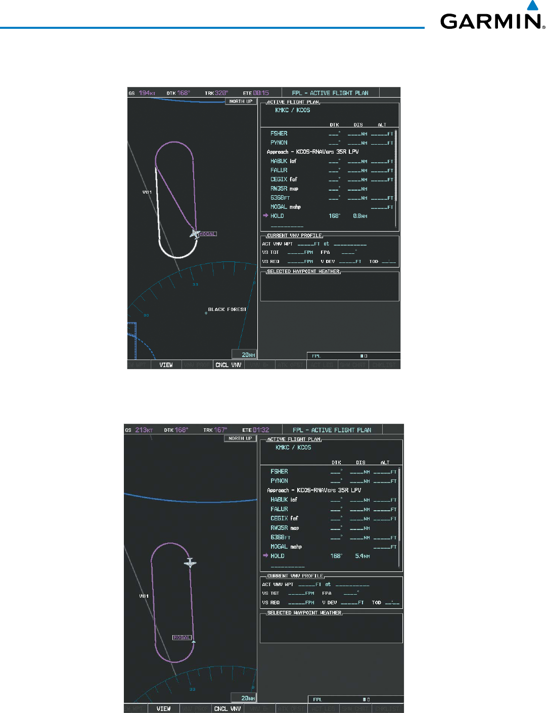
Garmin G1000 Pilot’s Guide for the Beechcraft 200/B200 Series
190-00928-04 Rev. A308
FLIGHT MANAGEMENT
26) The aircraft continues climbing to “AT or ABOVE” 10,000 feet at MOGAL. A holding pattern is established at
the MAHP (MOGAL) as shown in Figure 5-151.
Figure 5-151 Establishing the Holding Pattern
27) The aircraft maintains 10,000 feet while following the magenta line through the hold as in Figure 5-152.
Figure 5-152 Hold Established

190-00928-04 Rev. A
Garmin G1000 Pilot’s Guide for the Beechcraft 200/B200 Series
309
FLIGHT MANAGEMENT
5.12 ABNORMAL OPERATION
This section discusses the Dead Reckoning mode of operation and the subsequent indications.
NOTE: Dead Reckoning Mode only functions in Enroute (ENR) or Oceanic (OCN) phase of flight. In all other
phases, an invalid GPS solution produces a “NO GPS POSITION” annunciation on the map and the G1000
stops using GPS.
While in Enroute or Oceanic phase of flight, if the G1000 detects an invalid GPS solution or is unable to
calculate a GPS position, the system automatically reverts to Dead Reckoning (DR) Mode. In DR Mode, the G1000
uses its last-known position combined with continuously updated airspeed and heading data (when available) to
calculate and display the aircraft’s current estimated position.
It is important to note that estimated navigation data supplied by the G1000 in DR Mode may become increasingly
unreliable and must not be used as a sole means of navigation. If while in DR Mode airspeed and/or heading data
is also lost or not available, the DR function may not be capable of accurately tracking estimated position and,
consequently, the system may display a path that is different than the actual movement of the aircraft. Estimated
position information displayed by the G1000 through DR while there is no heading and/or airspeed data available
should not be used for navigation.
DR Mode is inherently less accurate than the standard GPS/SBAS Mode due to the lack of satellite measurements
needed to determine a position. Changes in wind speed and/or wind direction compound the relative inaccuracy
of DR Mode. Because of this degraded accuracy, other navigation equipment must be relied upon for position
awareness until GPS-derived position data is restored.
DR Mode is indicated on the G1000 by the appearance of the letters ‘DR’ superimposed in yellow over the
‘own aircraft’ symbol as shown in Figure 5-153. In addition, ‘DR’ is prominently displayed in yellow on the HSI
slightly above and to the right of the aircraft symbol on the CDI as shown in Figure 5-153. The CDI deviation
bar remains, but is removed from the display after 20 minutes in DR Mode. The autopilot will remain coupled
in DR mode as long as the deviation info is available (20 min.) Lastly, but at the same time, a ‘GPS NAV LOST’
alert message appears on the PFD. Normal navigation using GPS/SBAS source data resumes automatically once
a valid GPS solution is restored.
As a result of operating in DR Mode, all GPS-derived data is computed based upon an estimated position and
is displayed as yellow text on the display to denote degraded navigation source information as shown in Figure
5-153.
Also, while the G1000 is in DR Mode, some terrain functions are not available. Additionally, the accuracy of
all nearest information (airports, airspaces, and waypoints) is questionable. Finally, airspace alerts continue to
function, but with degraded accuracy.
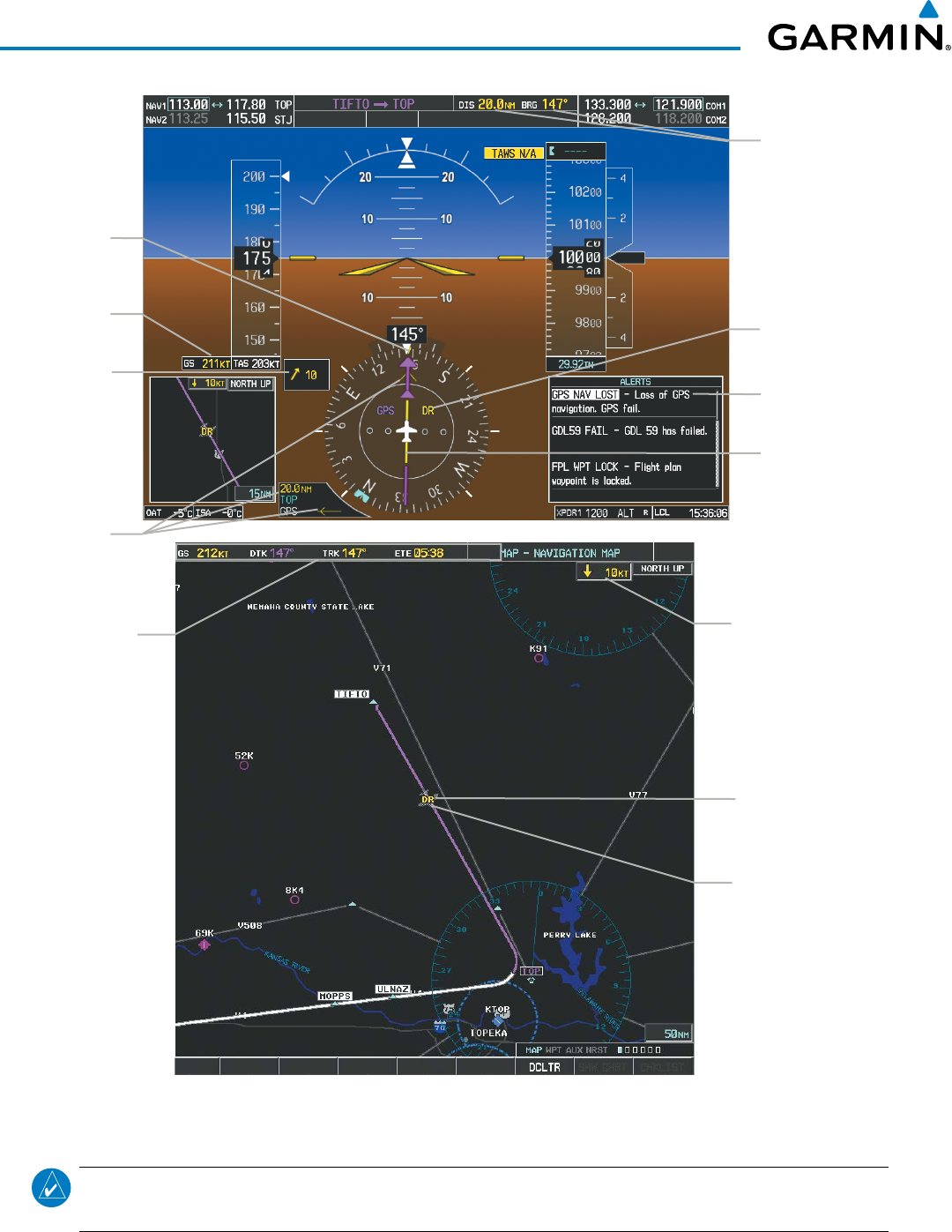
Garmin G1000 Pilot’s Guide for the Beechcraft 200/B200 Series
190-00928-04 Rev. A310
FLIGHT MANAGEMENT
Figure 5-153 Dead Reckoning Mode - GPS Derived Data Shown in Yellow
Distance &
Bearing
GPS Navigation
Lost Message
Dead Reckoning
Annunciaion
Dead Reckoning
Annunciation
Subdued Aircraft
Symbol
Nav Data Bar
All data except
Active Leg,
TAS, and DTK
are in yellow
Wind Data
Wind Data
Bearing
Pointer/
Distance
Current
Track
Indicator
Course
Deviation
Indicator
Ground
Speed
NOTE: The Inset Map is removed from the PFD any time aircraft pitch is greater than +30° or less than –20°,
or when a 65° bank angle is reached.

190-00928-04 Rev. A
Garmin G1000 Pilot’s Guide for the Beechcraft 200/B200 Series
311
HAZARD AVOIDANCE
SECTION 6 HAZARD AVOIDANCE
Hazard avoidance features available for the G1000 are designed to aid situational awareness and provide advisory
information with regard to potential hazards to flight safety associated with weather, terrain, and air traffic.
Weather
• GDL 69/69A SiriusXM Weather (Subscription Optional)
• GSR 56 Garmin Connext Weather (Optional)
• GWX 68/70 Airborne Color Weather Radar
• L-3 Stormscope® WX-500 Lightning Detection System (Optional)
Terrain Avoidance
• TAWS-B (Terrain Awareness and Warning System - Class B)
• TAWS-A (Terrain Awareness and Warning System - Class A) (Optional)
Traffic
• Traffic Information Service (TIS)
• Garmin GTS 800/820/825 Traffic Advisory System (TAS) (Optional)
• Garmin GTS 850/855 Traffic Alert and Collision Avoidance System I (TCAS I) (Optional)
• Garmin GTS 8000 Traffic Alert and Collision Avoidance System II (TCAS II) (Optional)
• L-3 SKYWATCH® SKY 497 TAS (Optional)
• L-3 SKYWATCH® HP SKY 899 TAS/TCAS I (Optional)
• Honeywell® KTA 870 TAS (Optional)
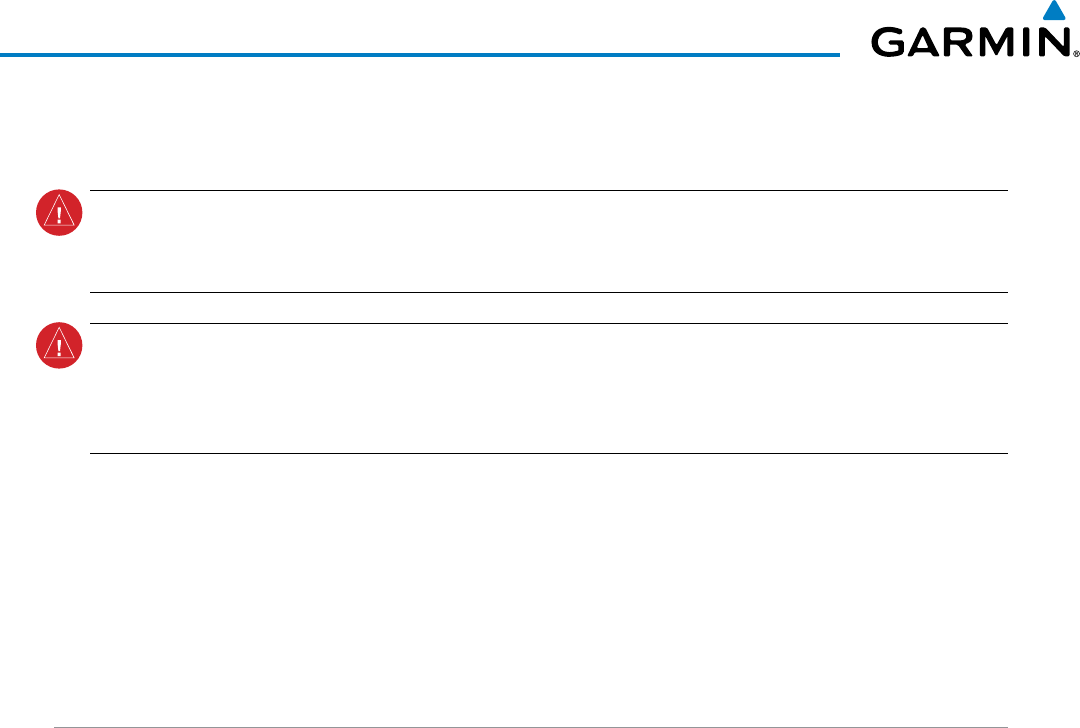
Garmin G1000 Pilot’s Guide for the Beechcraft 200/B200 Series
190-00928-04 Rev. A312
HAZARD AVOIDANCE
6.1 SIRIUSXM WEATHER
WARNING: Do not use data link weather information for maneuvering in, near, or around areas of hazardous
weather. Information contained within data link weather products may not accurately depict current
weather conditions.
WARNING: Do not use the indicated data link weather product age to determine the age of the weather
information shown by the data link weather product. Due to time delays inherent in gathering and processing
weather data for data link transmission, the weather information shown by the data link weather product
may be significantly older than the indicated weather product age.
The GDL 69/69A is a remote-mounted data link satellite receiver. It provides SiriusXM Weather data to the
system. The Multi Function Display (MFD) and the Primary Flight Display (PFD) Inset Map display the graphical
weather information and the associated text. The GDL 69A can also receive SiriusXM Satellite Radio entertainment
services. Both weather data and entertainment programming operate in the S-band frequency range to provide
continuous reception capabilities at any altitude throughout North America.
Services from SiriusXM are subscription-based. For more information on specific service packages, visit www.
siriusxm.com.
ACTIVATING SERVICES
Before SiriusXM Weather can be used, the service must be activated by providing SiriusXM’s customer service
the coded IDs unique to the installed GDL 69/69A. The SiriusXM Weather service has a coded Data Radio ID.
The Data Radio ID must be provided to activate the weather service. This ID is in the following locations:
• The AUX - XM Information Page on the MFD (Figure 6-1)
• The SiriusXM Activation Instructions included with the Data Link Receiver
• The label on the back of the Data Link Receiver
Contact the installer if the Audio and Data Radio IDs cannot be located.
SiriusXM uses the coded IDs to send an activation signal that allows the system to display weather data and/
or provide audio entertainment programming through the GDL 69/69A.
Establishing an account for SiriusXM services:
1) Select the XM Page in the Auxiliary Page Group.
2) Press the INFO Softkey to display the AUX - XM Information Page.
3) Note the Data Radio ID (for SiriusXM Weather) and/or the Audio Radio ID (for SiriusXM Satellite Radio).
4) Contact SiriusXM customer service through the phone number listed on its website.
5) Provide SiriusXM customer service the Data Radio ID and/or Audio Radio ID, in addition to payment information,
and desired weather product subscription package.
Activating the SiriusXM Weather service:
1) Once a SiriusXM Weather account has been established, select the XM Page in the Auxiliary Page Group.
2) Press the INFO Softkey to display the XM Information Page.
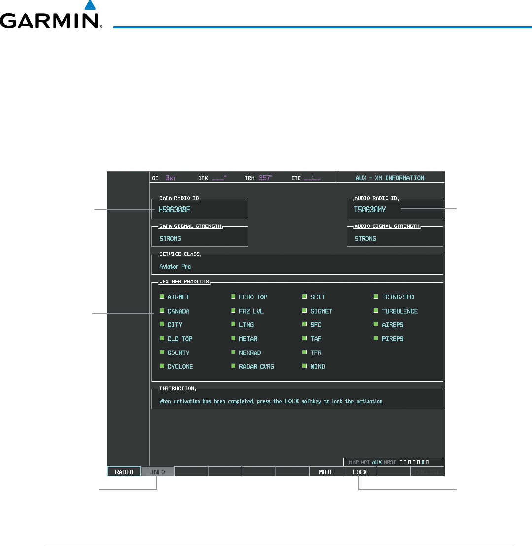
190-00928-04 Rev. A
Garmin G1000 Pilot’s Guide for the Beechcraft 200/B200 Series
313
HAZARD AVOIDANCE
3) Observe the list of Weather Products. A white empty box appears next to an unavailable weather product; a
green filled box appears next to an available weather product. During activation, it may take several minutes
for weather products in the selected subscription package to become available.
4) When the available weather products displayed match the weather products offered in the selected SiriusXM
Weather product subscription package, press the LOCK Softkey.
5) Turn the large FMS Knob to highlight ‘YES’.
6) To complete activation, press the ENT Key.
Select
INFO
Softkey to
Display XM
Information Page
Weather
Products
(Available
Products for
Service Class
Indicated in
Green)
Select
LOCK
Softkey to Lock
Subscription
Information
Figure 6-1 XM Information Page
Audio Radio ID
(for SiriusXM
Satellite Radio)
Data Radio
ID (for XM
Weather)
USING SIRIUSXM WEATHER PRODUCTS
The principal map page for viewing SiriusXM Weather data is the Weather Data Link (XM) Page in the Map
Page Group. This is the only map display capable of showing information for all available SiriusXM Weather
products.
Viewing the Weather Data Link (XM) Page:
1) Turn the large
FMS
Knob to select the Map Page Group.
2) Turn the small
FMS
Knob
to select the Weather Data Link (XM or CNXT) Page.
3) If the page title contains ‘CNXT’, it will be necessary to change the data link weather source from Garmin
Connext to SiriusXM Weather. Refer to the next procedure to change the source.
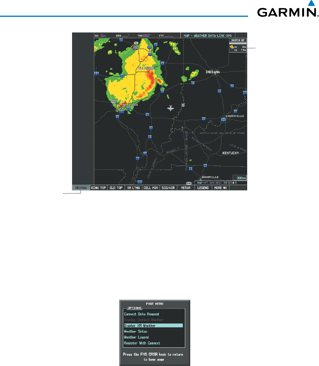
Garmin G1000 Pilot’s Guide for the Beechcraft 200/B200 Series
190-00928-04 Rev. A314
HAZARD AVOIDANCE
NEXRAD
Weather
Product Icon
and Age
(U.S. and
Canada)
NEXRAD Weather
Product Selected
for Display Figure 6-2 Weather Data Link (XM) Page
Changing the weather data link source (SiriusXM or Garmin Connext):
1) If necessary, turn the large FMS Knob to select the Map Page Group.
2) If necessary, turn the small FMS Knob to select the Weather Data Link (XM or CNXT) Page.
3) Press the MENU Key (Figure 6-3).
4) If necessary, turn the large FMS Knob to highlight ‘Display XM Weather’ or ‘Display Connext Weather’ and press
the ENT Key. Weather Data Link Page title and softkeys change to correspond to selected data link weather
source.
Figure 6-3 Changing the Data
Link Weather Source

190-00928-04 Rev. A
Garmin G1000 Pilot’s Guide for the Beechcraft 200/B200 Series
315
HAZARD AVOIDANCE
For each enabled SiriusXM Weather product, the system displays a weather product icon and product age.
The product age is the elapsed time (in minutes) since the weather data provider compiled the weather product.
The product age display does not indicate the age of the information contained within the weather product,
which can be significantly older than the displayed weather product age.
The weather product icon and age may be enabled/disabled on the PFD Inset Map.
Enabling/Disabling Weather Product Information on the PFD Inset Map:
1) Press the INSET Softkey.
2) Press the WX LGND Softkey to display or remove weather product info and age data when a data link weather
product is selected for display on the PFD Inset Map.
The SiriusXM Weather service broadcasts weather products at specific intervals (defined in the Broadcast
Rate column in Table 6-1). If for any reason, a product is not refreshed within the Broadcast Rate intervals
(see Table 6-1), the system removes the expired data from the display, and shows dashes instead of the product
age. This ensures the displayed information is consistent with what is currently being transmitted by the
SiriusXM Weather service. If more than half of the expiration time has elapsed, the color of the product age
changes to yellow. If data for a weather product is not available, the system displays ‘N/A’ next to the weather
product symbol instead of the product age.
Table 6-1 shows the weather product symbols, the expiration times and the broadcast rates. The broadcast
rate represents the interval at which the SiriusXM Weather service transmits new signals that may or may not
contain updated weather products. It does not represent the rate at which the weather information is updated
or when the Data Link Receiver receives new data. SiriusXM and its weather data suppliers define and control
the data update intervals, which are subject to change.
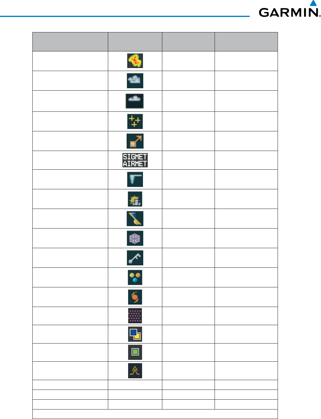
Garmin G1000 Pilot’s Guide for the Beechcraft 200/B200 Series
190-00928-04 Rev. A316
HAZARD AVOIDANCE
SiriusXM Weather Product Symbol Expiration Time
(Minutes)
Broadcast Rate
(Minutes)
NEXRAD 30 5 (U.S.)
10 (Canada)
Cloud Top (CLD TOP) 60 15
Echo Top (ECHO TOP) 30 7.5
XM Lightning (LTNG) 30 5
Cell Movement (CELL MOV) 30 1.25
SIGMETs/AIRMETs (SIG/AIR) 60 12
METARs 90 12
City Forecast (CITY) 90 12
Surface Analysis (SFC) 60 12
Freezing Levels (FRZ LVL) 120 12
Winds Aloft (WIND) 90 12
County Warnings (COUNTY) 60 5
Cyclone Warnings (CYCLONE) 60 12
Icing Potential (CIP and SLD)
(ICNG) 90 22
Pilot Weather Report
(PIREPs) 90 12
Air Report
(AIREPs) 90 12
Turbulence
(TURB) 180 12
Radar Coverage Not Available No product image 30 5
TFRs No product image 60 12
TAFs No product image 60 12
Table 6-1 SiriusXM Weather Product Symbols and Data Timing
190-00928-04 Rev. A
Garmin G1000 Pilot’s Guide for the Beechcraft 200/B200 Series
317
HAZARD AVOIDANCE
Table 6-2 shows which SiriusXM Weather products can be displayed (indicated with a ‘+’ symbol) on specific
maps.
SiriusXM Weather
Product
PFD Inset Map
Navigation Map Page
Weather Data Link
Page
Weather Information
Page
AUX - Trip Planning
Page
Nearest Page Group
Flight Plan Pages
NEXRAD + + + + + +
Cloud Top (CLD TOP) +
Echo Top (ECHO TOP) +
SitiusXM Lightning (LTNG) + + + + + +
Cell Movement (CELL MOV) + + +
SIGMETs/AIRMETs (SIG/AIR) +
METARs + + + + + + +
City Forecast (CITY) +
Surface Analysis (SFC) +
Freezing Levels (FRZ LVL) +
Winds Aloft (WIND) +* +
County Warnings (COUNTY) +
Cyclone Warnings (CYCLONE) +
Icing Potential (ICNG) +
PIREPs + +
AIREPs + +
Turbulence (TURB) +
Radar Coverage + +
TFRs +++++++
TAFs + +
* Winds Aloft data is available inside Profile View when Profile View is enabled on the Navigation
Map Page (TAWS-B installations only).
Table 6-2 Weather Product Display Maps
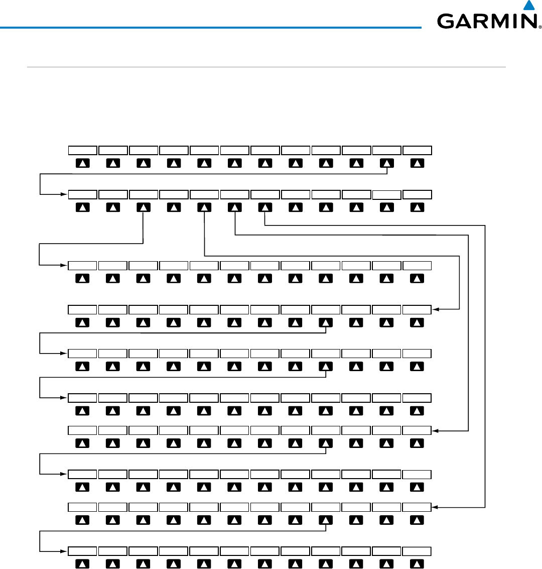
Garmin G1000 Pilot’s Guide for the Beechcraft 200/B200 Series
190-00928-04 Rev. A318
HAZARD AVOIDANCE
WEATHER SOFTKEYS ON THE WEATHER DATA LINK (XM) PAGE
Softkeys control the display of weather information on most MFD pages and the PFD Inset Map (Figure
6-4 shows the weather product softkeys for the Weather Data Link (XM) Page). When a weather product
is selected for display, the corresponding softkey label changes to gray to indicate the product is enabled.
Unavailable weather products have subdued softkey labels (softkeys are disabled from selection).
Figure 6-4 Weather Data Link (XM) Page Weather Product Softkeys
Select the BACK Softkey
to move up one level.
COUNTYFRZ LVLBACK
NEXRAD MORE WX
XM LTNGCLD TOP
ICNG OFF
ECHO TOP
CELL MOV
SIG/AIR METAR
LEGEND
CHKLIST
SFC OFF
CYCLONE
24 HR
36 HR 12 HR BACK
LEGEND
CURRENT
48 HR
OFF
9000
12000 6000 BACK
LEGEND
3000
15000
SFC
PREV OFF NEXT
27000
30000 24000 BACK
LEGEND
21000
33000
18000
PREV OFF NEXT
42000 BACK
LEGEND
39000
36000
PREV OFF NEXT
SFC Softkey label changes
to reflect current selection.
WIND/ICNG/TURB Softkey labels
change to reflect current selection.
PREV and NEXT Softkeys cycle through Winds Aloft,
Icing, and Turbulence altitude selection softkeys.
WIND OFF
TURB OFF AIREPS PIREPS
9000
120006000 BACK
LEGEND
3000
15000
1000
PREV OFF NEXT
27000
3000024000BACK
LEGEND
21000
18000
PREV OFF NEXT
30000
3300027000BACK
LEGEND
24000
36000
21000
PREV OFF NEXT
45000BACK
LEGEND
42000
39000
PREV OFF NEXT
The setup menus for the Navigation Map Page and the Weather Data Link (XM) Page control the map range
settings above which weather products data are decluttered from the display. If a map range larger than the
weather product map range setting is selected, the weather product data is removed from the map. The menus
also provide a means in addition to the softkeys for enabling/disabling display of weather products.
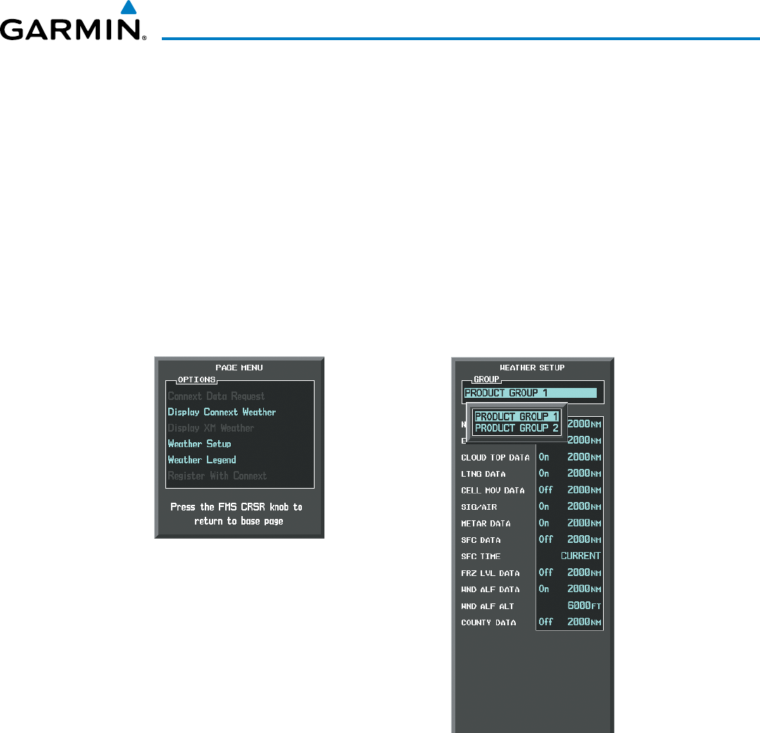
190-00928-04 Rev. A
Garmin G1000 Pilot’s Guide for the Beechcraft 200/B200 Series
319
HAZARD AVOIDANCE
Setting up and customizing the Weather Data Link (XM) Page:
1) Select the Weather Data Link (XM) Page.
2) Press the
MENU
Key.
3) With ‘Weather Setup’ highlighted, press the
ENT
Key (Figure 6-5).
4) Turn the small
FMS
Knob to select ‘PRODUCT GROUP 1’ or ‘PRODUCT GROUP 2’, and press the
ENT
Key (Figure
6-6).
5) Turn the large
FMS
Knob or press the
ENT
Key to scroll through product selections.
6) Turn the small
FMS
Knob to scroll through options for each product (ON/OFF, range settings, etc.).
7) Press the
ENT
Key to select an option.
8) Press the FMS Knob or CLR Key to return to the Weather Data Link (XM) Page with the changed settings.
Figure 6-6 Weather Data Link (XM) Page Setup Menu
Figure 6-5 Weather Data Link (XM) Page Menu
Restoring default Weather Data Link (XM) Page settings:
1) Select the Weather Data Link (XM) Page.
2) Press the MENU Key.
3) With ‘Weather Setup’ highlighted, press the
ENT
Key.
4) Press the
MENU
Key.
5) Highlight the desired default(s) to restore (all or for selection) and press ENT Key.
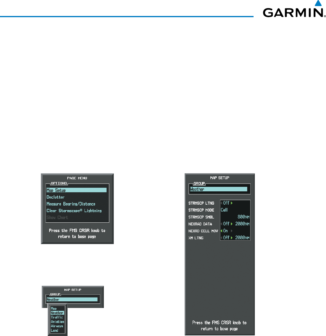
Garmin G1000 Pilot’s Guide for the Beechcraft 200/B200 Series
190-00928-04 Rev. A320
HAZARD AVOIDANCE
Maps besides the Weather Data Link (XM) Page use settings based on those selected for the Navigation Map
Page.
Setting up and customizing weather data for the Navigation Map Page:
1) Select the Navigation Map Page.
2) Press the MENU Key.
3) With ‘Map Setup’ highlighted, press the
ENT
Key (Figure 6-7).
4) Turn the small FMS Knob to select the ‘Weather’ Group and press the ENT Key (Figure 6-8).
5) Turn the large
FMS
Knob or press the
ENT
Key to scroll through product selections (Figure 6-9).
6) Turn the small
FMS
Knob to scroll through options for each product (ON/OFF, range settings).
7) Press the
ENT
Key to select an option.
8) Press the FMS Knob or CLR Key to return to the Navigation Map Page with the changed settings.
Figure 6-8 Navigation Map Page Setup Menu
Figure 6-7 Navigation Map Page Menu
Figure 6-9 Navigation Map Page Setup Menu, Weather Group
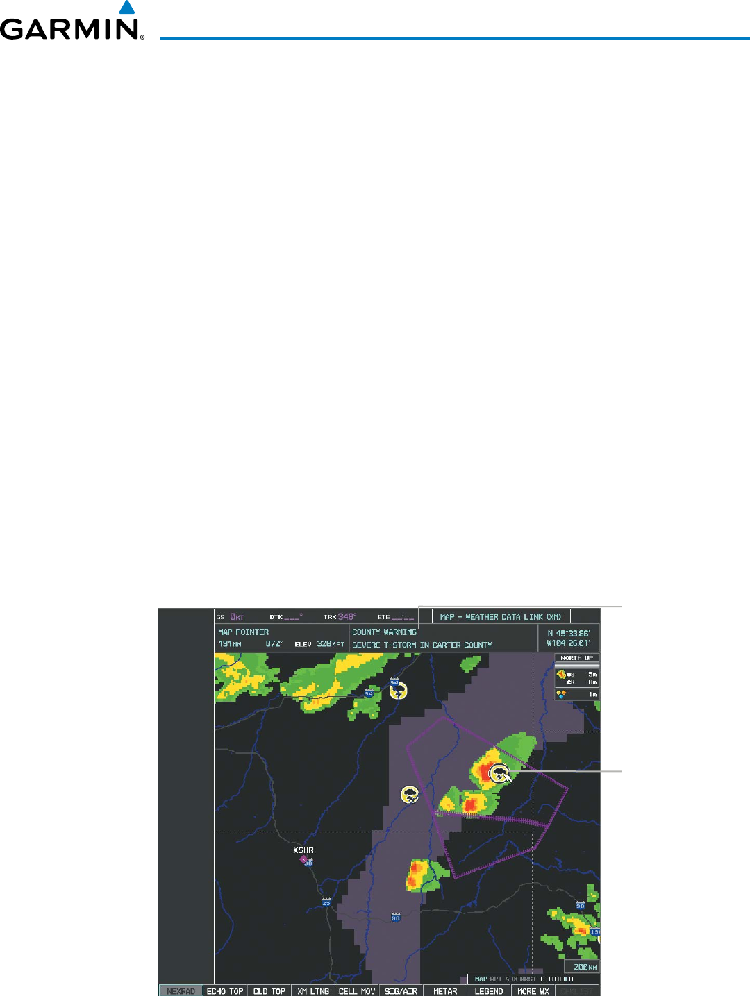
190-00928-04 Rev. A
Garmin G1000 Pilot’s Guide for the Beechcraft 200/B200 Series
321
HAZARD AVOIDANCE
Each active weather product has an associated legend which can be displayed on the Weather Data Link (XM)
Page.
Viewing legends for displayed weather products
1) Select the Weather Data Link (XM) Page.
2) Select the LEGEND Softkey to display the legends for the displayed weather products.
Or:
a) Press the MENU Key.
b) Select ‘Weather Legend’ and press the ENT Key.
3) Turn the FMS Knob to scroll through the legends if more are available than fit in the window.
4) To remove the Legend Window, select the LEGEND Softkey, the ENT or the CLR Key, or press the FMS Knob.
Additional information about the following can be displayed by panning over the display on the map:
• Echo Tops
• Cell Movement
• SIGMETs
• AIRMETs
• METARs
• County Warnings
• TFRs
• AIREPs
• PIREPs
The map panning feature is enabled by pressing the RANGE Knob. The map range is adjusted by turning
the RANGE Knob. If the map range is adjusted while panning is enabled, the map is re-centered on the Map
Pointer.
Figure 6-10 Panning on the Weather Data Link (XM) Page
Additional
Information
on Weather
Feature
Selected with
Map Pointer
Severe
Thunderstorm
Warning Selected
with Map Pointer
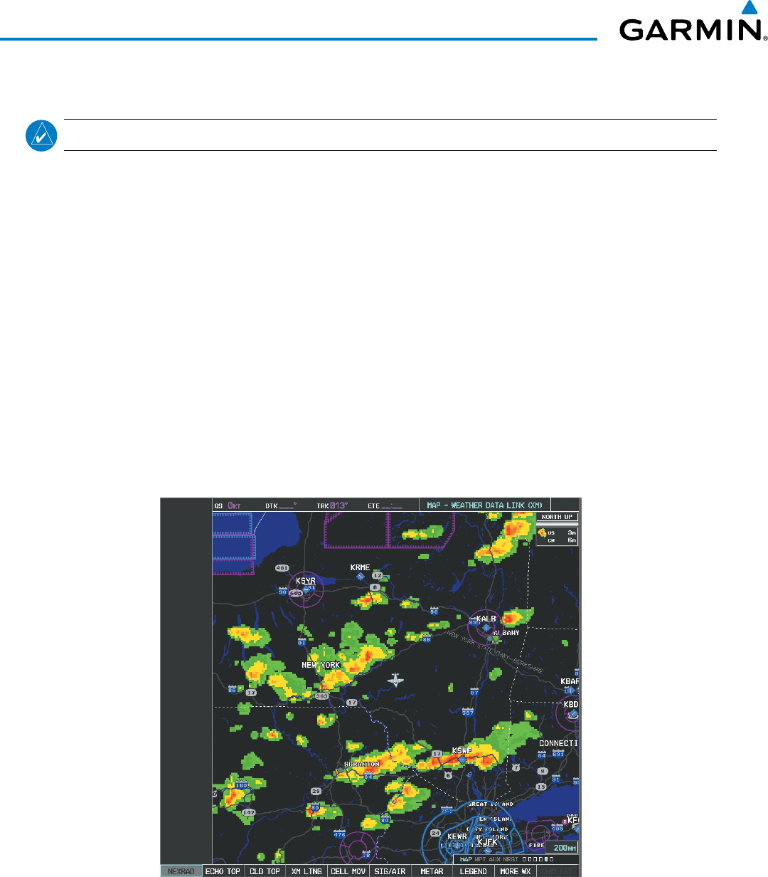
Garmin G1000 Pilot’s Guide for the Beechcraft 200/B200 Series
190-00928-04 Rev. A322
HAZARD AVOIDANCE
NEXRAD
NOTE: NEXRAD data cannot be displayed at the same time as terrain, echo tops, icing, or turbulence data.
The National Weather Service (NWS) operates the WSR-88D, or NEXRAD (NEXt-generation RADar)
system, an extensive network of 156 high-resolution Doppler radar systems. The NEXRAD network provides
centralized meteorological information for the continental United States and selected overseas locations. The
maximum range of a single NEXRAD site is 250 nm.
Individual NEXRAD sites supply the network with radar images, and the images from each radar site may
arrive at the network at different rates and times. Periodically, the weather data provider compiles the available
individual site images from the network to form a composite image, and assigns a single time to indicate when
it created the image. This image becomes the NEXRAD weather product. Individual images--gathered from
each NEXRAD site--differ in age, and are always older than the displayed NEXRAD weather product age. The
data provider then sends the NEXRAD data to the SiriusXM Weather service, whose satellites transmit this
information during the next designated refresh time for the NEXRAD weather product.
Because of the time required to detect, assemble, and distribute the NEXRAD weather product, the displayed
weather information contained within the product may be significantly older than the current radar synopsis
and may not depict the current weather conditions. NEXRAD information should never be used as a basis for
maneuvering in, near, or around areas of hazardous weather regardless of the information it contains.
Figure 6-11 NEXRAD Data on the Weather Data Link (XM) Page
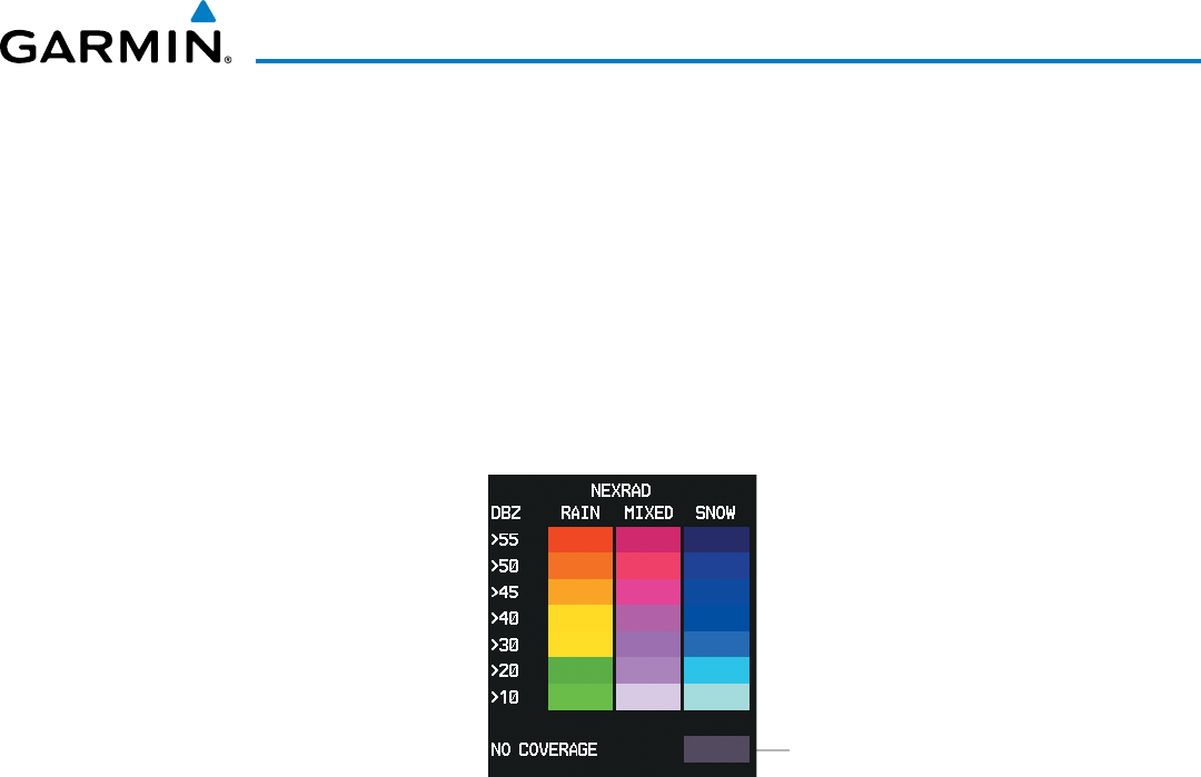
190-00928-04 Rev. A
Garmin G1000 Pilot’s Guide for the Beechcraft 200/B200 Series
323
HAZARD AVOIDANCE
Displaying NEXRAD weather information:
1) Select the MAP Softkey (for the PFD Inset Map, press the INSET Softkey). This step is not necessary on the
Weather Data Link (XM) Page.
2) Select the NEXRAD Softkey.
Composite data from all the NEXRAD radar sites in the United States is shown. This data is composed of
the maximum reflectivity from the individual radar sweeps. The display of the information is color-coded
to indicate the weather severity level. All weather product legends can be viewed on the Weather Data Link
(XM) Page. For the NEXRAD legend (Figure 6-12), select the
LEGEND
Softkey when NEXRAD is selected for
display.
No Radar Coverage
Figure 6-12 NEXRAD Data with Legend
The display of radar coverage is always active when either NEXRAD or Echo Tops is selected. Areas where
NEXRAD radar coverage and Echo Tops information is not currently available or is not being collected are
indicated in gray shade of purple.
ReFlectivity
Reflectivity is the amount of transmitted power returned to the radar receiver. Colors on the NEXRAD
display are directly correlative to the level of detected reflectivity. Reflectivity as it relates to hazardous
weather can be very complex.
The role of radar is essentially to detect moisture in the atmosphere. Simply put, certain types of weather
reflect radar better than others. The intensity of a radar reflection is not necessarily an indication of the
weather hazard level. For instance, wet hail returns a strong radar reflection, while dry hail does not. Both
wet and dry hail can be extremely hazardous.
The different NEXRAD echo intensities are measured in decibels (dB) relative to reflectivity (Z). NEXRAD
measures the radar reflectivity ratio, or the energy reflected
back to
the radar receiver (
designated by the
letter Z)
. The value of Z increases as the returned signal strength increases.
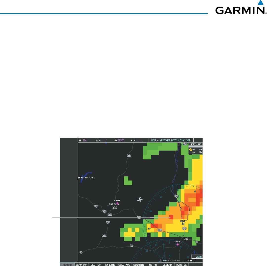
Garmin G1000 Pilot’s Guide for the Beechcraft 200/B200 Series
190-00928-04 Rev. A324
HAZARD AVOIDANCE
neXRaD liMitationS
NEXRAD radar images may have certain limitations:
• NEXRAD base reflectivity does not provide sufficient information to determine cloud layers or precipitation
characteristics (wet hail vs. rain). For example, it is not possible to distinguish between wet snow, wet
hail, and rain.
• NEXRAD base reflectivity is sampled at the minimum antenna elevation angle. An individual NEXRAD
site cannot depict high altitude storms at close ranges. It has no information about storms directly over
the site.
• When zoomed in to a range of 30 nm, each square block on the display represents an area of four square
kilometers. The intensity level reflected by each square represents the
highest
level of NEXRAD data
sampled within the area (Figure 6-13).
• If the precipitation type is unknown, the system displays the precipitation as rain, regardless of actual
precipitation type.
Figure 6-13 NEXRAD Data - Zoomed
Block represents
4 km
2
The following may cause abnormalities in displayed NEXRAD radar images:
• Ground clutter
• Strobes and spurious radar data
• Sun strobes (when the radar antenna points directly at the sun)
• Interference from buildings or mountains, which may cause shadows
• Metallic dust from military aircraft, which can cause alterations in radar scans
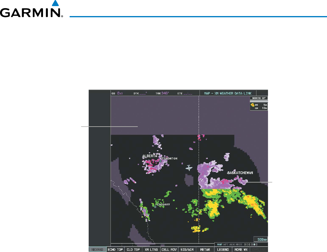
190-00928-04 Rev. A
Garmin G1000 Pilot’s Guide for the Beechcraft 200/B200 Series
325
HAZARD AVOIDANCE
neXRaD liMitationS (canaDa)
• Radar coverage extends to 55ºN.
• Any precipitation displayed between 52ºN and 55ºN is displayed as mixed precipitation.
• If the precipitation type is unknown, the system displays the precipitation as rain, regardless of actual
precipitation type.
Figure 6-14 NEXRAD Data - Canada
Precipitation Above
52°N Displays as
Mixed
No Coverage
Above 55°N

Garmin G1000 Pilot’s Guide for the Beechcraft 200/B200 Series
190-00928-04 Rev. A326
HAZARD AVOIDANCE
ECHO TOPS
NOTE: Echo Tops cannot be displayed at the same time as Cloud Tops or NEXRAD data is displayed.
The Echo Tops weather product (Figure 6-15) shows the location, elevation, and direction of the highest
radar echo. The highest radar echo does not indicate the top of a storm or clouds; rather it indicates the
highest altitude at which precipitation is detected. Information is derived from NEXRAD data.
Figure 6-15 Echo Tops Weather Product on the Weather Data Link (XM) Page
Displaying Echo Tops information:
1) Select the Weather Data Link (XM) Page.
2) Select the ECHO TOPS Softkey.
To display the Echo Tops legend (Figure 6-16), select the
LEGEND
Softkey when Echo Tops is selected for
display. Since Echo Tops and Cloud Tops use the same color scaling to represent altitude, display of these
weather products is mutually exclusive. When Echo Tops is activated, NEXRAD and Cloud Tops data are
removed.
Figure 6-16 Echo Tops Legend
No Radar Coverage
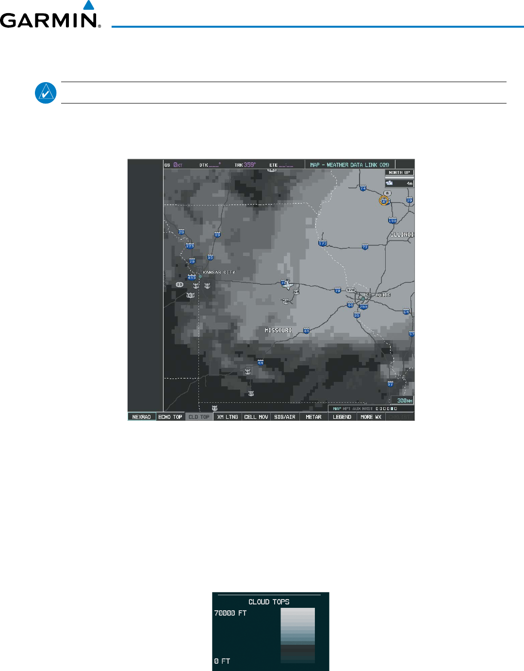
190-00928-04 Rev. A
Garmin G1000 Pilot’s Guide for the Beechcraft 200/B200 Series
327
HAZARD AVOIDANCE
CLOUD TOPS
NOTE: Cloud Tops and Echo Tops cannot be displayed at the same time.
The Cloud Tops weather product (Figure 6-17) depicts cloud top altitudes as determined from satellite
imagery.
Figure 6-17 Cloud Tops Weather Product
Displaying Cloud Tops information:
1) Select the Weather Data Link (XM) Page with the
FMS
Knob.
2) Select the CLD TOP Softkey.
To display the Cloud Tops legend (Figure 6-18), select the LEGEND Softkey when Cloud Tops is selected
for display. Since Cloud Tops and Echo Tops use the same color scaling to represent altitude, display of these
weather products is mutually exclusive. When Cloud Tops is activated, Echo Tops data is removed.
Figure 6-18 Cloud Tops Legend
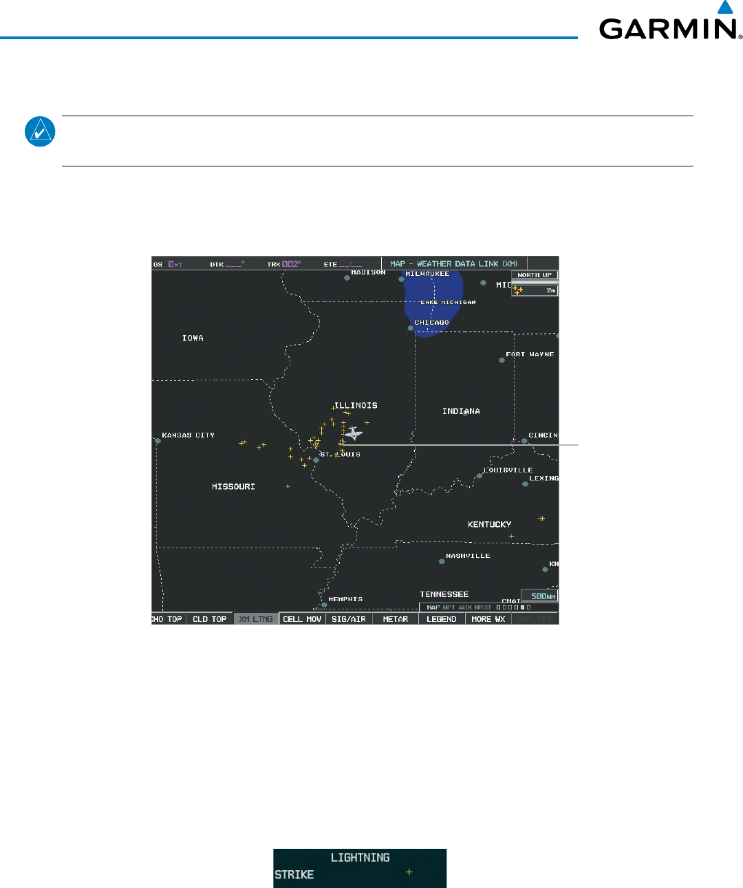
Garmin G1000 Pilot’s Guide for the Beechcraft 200/B200 Series
190-00928-04 Rev. A328
HAZARD AVOIDANCE
SIRIUSXM LIGHTNING
NOTE: SiriusXM Lightning information cannot be displayed simultaneously on the same map as information
from an optional on-board lightning detection system.
The SiriusXM Lightning weather product (Figure 6-19) shows the approximate location of cloud-to-ground
lightning strikes. A strike icon represents a strike that has occurred within a two-kilometer region. The exact
location of the lightning strike is not displayed.
Lightning
Strikes
Figure 6-19 SiriusXM Lightning Weather Product on the
Weather Data Link (XM) Page
Displaying SiriusXM Lightning information:
1) Select the MAP Softkey (for the PFD Inset Map, press the INSET Softkey). This step is not necessary on the
Weather Data Link (XM) Page.
2) Select the XM LTNG Softkey (LTNG Softkey on the Weather Data Link (XM) Page).
To display the XM Lightning legend on the Weather Data Link (XM) Page (Figure 6-20), select the
LEGEND
Softkey when XM Lightning is selected for display.
Figure 6-20 SiriusXM Lightning Legend
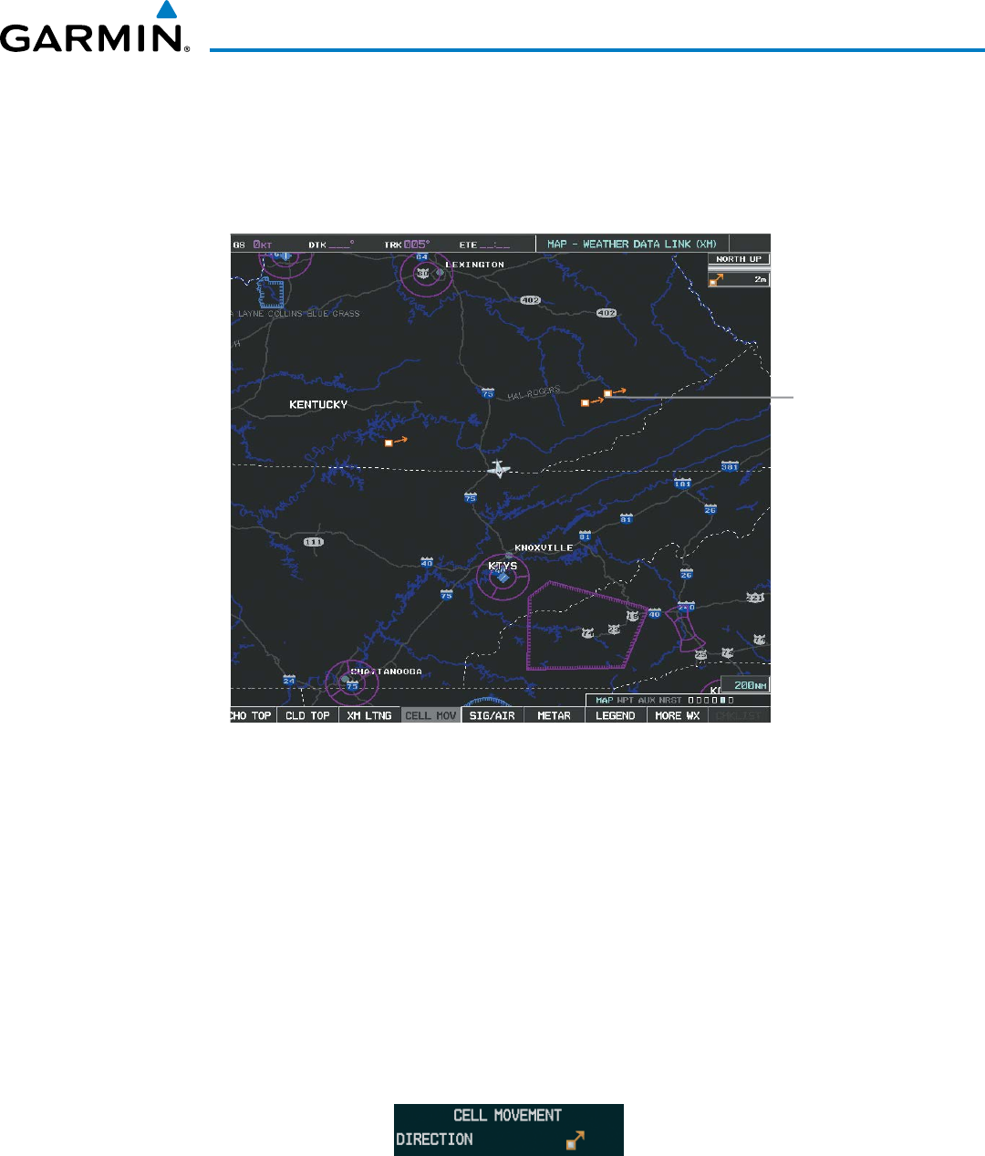
190-00928-04 Rev. A
Garmin G1000 Pilot’s Guide for the Beechcraft 200/B200 Series
329
HAZARD AVOIDANCE
CELL MOVEMENT
Cell Movement data (Figure 6-21) shows the location and movement of storm cells as identified by the
ground-based system. Cells are represented by yellow squares, with direction of movement indicated with
short, orange arrows.
Figure 6-21 Cell Movement Data
Storm
Cells
On most applicable maps, Cell Movement data is selected for display along with NEXRAD. On the Weather
Data Link (XM) Page, Cell Movement data can be selected independently.
Displaying Cell Movement information:
1) Select the MAP Softkey (for the PFD Inset Map, press the INSET Softkey). This step is not necessary on the
Weather Data Link (XM) Page.
2) Select the NEXRAD Softkey (CEL MOV Softkey on the XM Weather Data Link (XM) Page). For Cell Movement
to be displayed on maps other than the Weather Data Link (XM) Page, Cell Movement must be turned on in the
Navigation Map Setup Menu (see “Setting Up XM Satellite Weather”).
To display the Cell Movement legend on the Weather Data Link (XM) Page, (Figure 6-22), select the
LEGEND
Softkey when Cell Movement is selected for display.
Figure 6-22 Cell Movement Legend
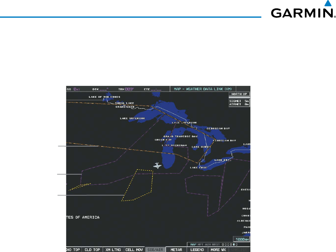
Garmin G1000 Pilot’s Guide for the Beechcraft 200/B200 Series
190-00928-04 Rev. A330
HAZARD AVOIDANCE
SIGMETS AND AIRMETS
SIGMET (SIGnificant METeorological Information) and AIRMET (AIRmen’s METeorological Information)
are issued for potentially hazardous weather. A Convective SIGMET is issued for hazardous convective
weather such as severe or widespread thunderstorms. A localized SIGMET is a significant weather condition
occurring at a localized geographical position.
Figure 6-23 SIGMET/AIRMET Data
Convective
Sigmet
Airmet
Airmet
Turbulence
Displaying SIGMETs and AIRMETs:
1) Select the Weather Data Link (XM) Page.
2) Select the SIG/AIR Softkey.
3) To view the text of the
SIGMET or AIRMET, press the
RANGE Knob
and move the Map Pointer over the icon.
4)
Press the ENT key. Figure 6-24 shows sample SIGMET text.
To display the SIGMET and AIRMET legend (Figure 6-24), select the
LEGEND
Softkey when SIGMETs and
AIRMETs are selected for display.
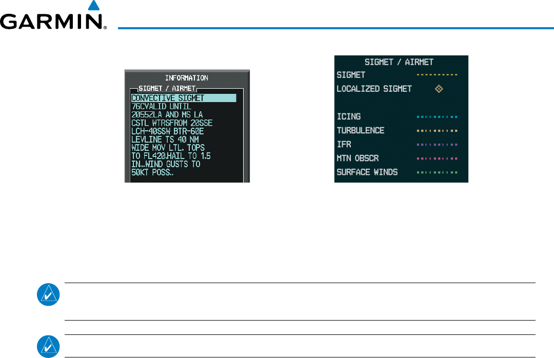
190-00928-04 Rev. A
Garmin G1000 Pilot’s Guide for the Beechcraft 200/B200 Series
331
HAZARD AVOIDANCE
Sample SIGMET Text SIGMET/AIRMET Legend
Figure 6-24 SIGMET/AIRMET Text and Legend
METARS AND TAFS
NOTE: Atmospheric pressure as reported for METARs is given in hectopascals (hPa), except for in the United
States, where it is reported in inches of mercury (in Hg). Temperatures are reported in Celsius.
NOTE: METAR information is only displayed within the installed navigation database service area.
METARs (METeorological Aerodrome Reports) typically contain information about the temperature,
dewpoint, wind, precipitation, cloud cover, cloud heights, visibility, and barometric pressure at an airport or
observation station. They can also contain information on precipitation amounts, lightning, and other critical
data. METARs reflect hourly observations; non-routine updates include the code “SPECI” in the report.
METARs are shown as colored flags at airports that provide them.
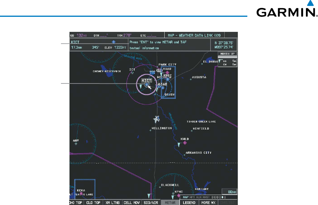
Garmin G1000 Pilot’s Guide for the Beechcraft 200/B200 Series
190-00928-04 Rev. A332
HAZARD AVOIDANCE
Figure 6-25 METAR Flags on the Weather Data Link (XM) Page
Instructions
for Viewing
METAR and
TAF Text
Selected
Airport
TAFs (Terminal Aerodrome Forecasts) are weather predictions for specific airports within a 24- hour period,
and may span up to 36 hours. TAFs typically include forecast wind, visibility, weather phenomena, and sky
conditions using METAR codes.
METAR and TAF text are displayed on the Weather Information Page. METAR data is displayed first in a
decoded fashion, followed by the original text. Note the original text may contain additional information not
found in the decoded version. TAF information is displayed only in its original form when TAFs are available.
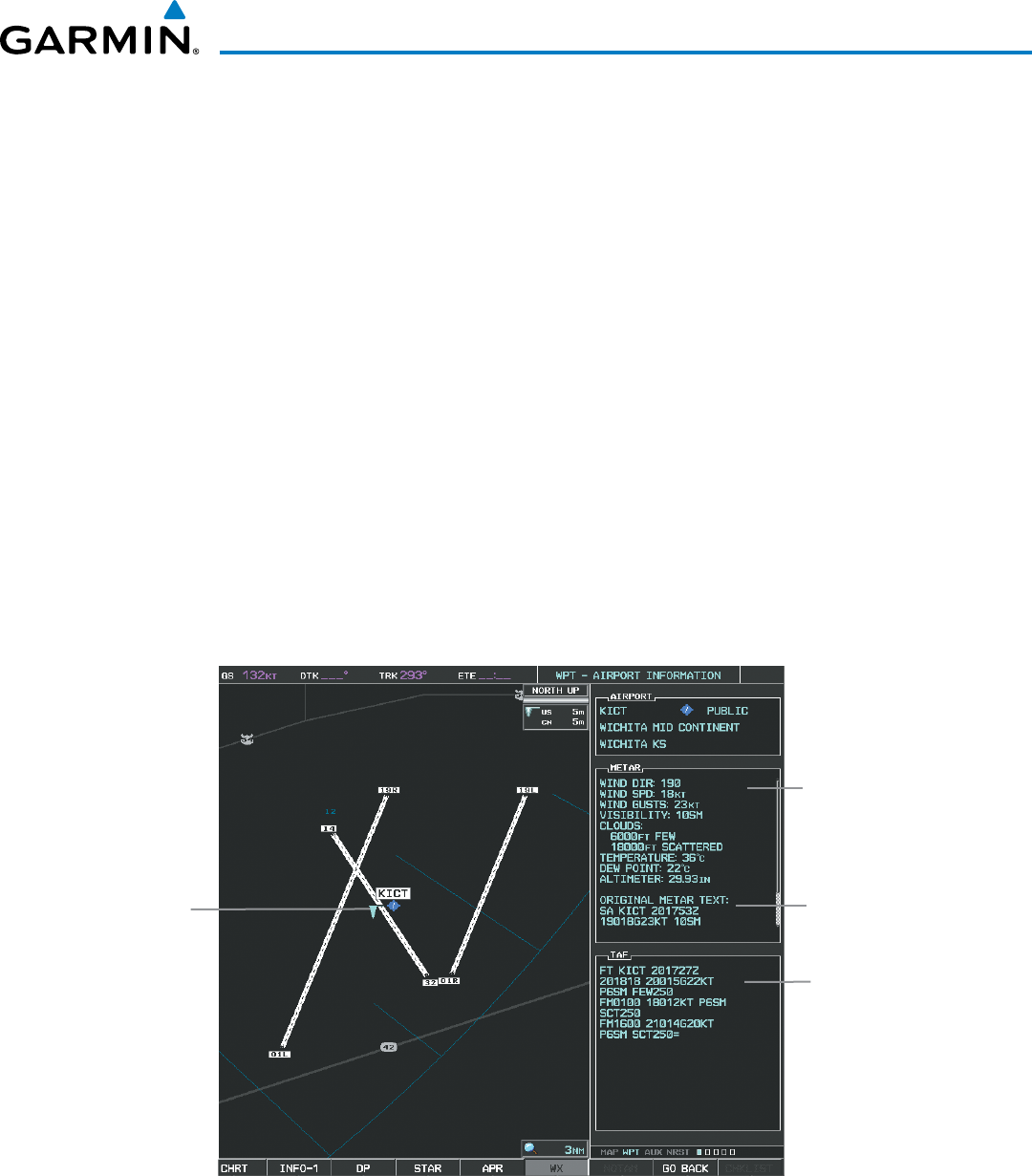
190-00928-04 Rev. A
Garmin G1000 Pilot’s Guide for the Beechcraft 200/B200 Series
333
HAZARD AVOIDANCE
Displaying METAR and TAF text:
1) On the Weather Data Link (XM) Page, select the METAR Softkey.
2) Press the RANGE Knob and pan to the desired airport.
3) Press the ENT Key. The Weather Information Page is shown with METAR and TAF text.
4) Use the FMS Knob or the ENT Key to scroll through the METAR and TAF text. METAR text must be completely
scrolled through before scrolling through the TAF text.
5) Press the FMS Knob or the CLR Key to return to the XM Weather Data Link (XM) Page.
Or:
1) Select the Weather Information Page.
a) Turn the large
FMS
Knob to select the Waypoint Page Group.
b) Select the WX Softkey to select the Weather Information Page.
2) Press the FMS Knob to display the cursor.
3) Use the FMS Knob to enter the desired airport and press the
ENT
Key.
4) Use the FMS Knob or the ENT Key to scroll through the METAR and TAF text. Note that the METAR text must
be completely scrolled through before scrolling through the TAF text.
Original
TAF Text
METAR
Symbol
Decoded
METAR
Text
Figure 6-26 METAR and TAF Information on the Airport Information Page
Original
METAR
Text
Original METAR text is also accessible while panning the map cursor over a METAR flag on any map page
on which a METAR is displayed. The METAR text is shown in a box near the METAR flag.
In addition, METAR flags and their associated text are displayed on the Active Flight Plan Page on the MF.D.
The system shows a METAR flag next to waypoints in the flight plan with an available METAR.
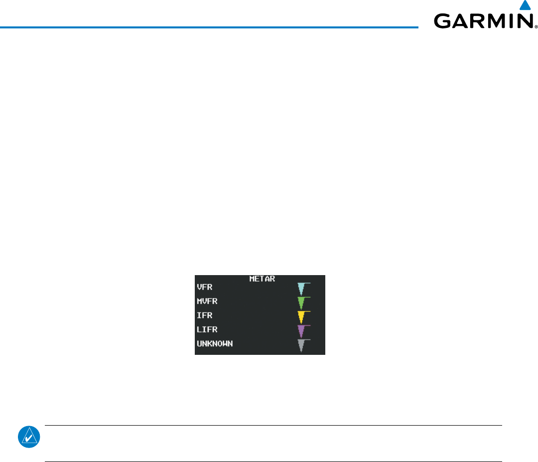
Garmin G1000 Pilot’s Guide for the Beechcraft 200/B200 Series
190-00928-04 Rev. A334
HAZARD AVOIDANCE
Displaying original METAR text on the Active Flight Plan Page:
1) Select the Active Flight Plan Page on the MFD.
2) Press the FMS Knob to activate the cursor.
3) Turn the large FMS Knob to highlight a waypoint with an available METAR (indicated with a METAR flag next
to it). The METAR text will appear in the ‘SELECTED WAYPOINT WEATHER’ window below.
4) When finished, press the FMS Knob to remove the cursor or press the FPL Key to exit the Active Flight Plan
Page.
To display the METAR legend (Figure 6-27) on the Weather Data Link (XM) Page, select the LEGEND
Softkey when METARs are selected for display.
The METAR flag color is determined by the information in the METAR text. The system displays a gray
METAR flag when the system cannot determine the METAR category based on the information available.
Figure 6-27 METAR Legend
SURFACE ANALYSIS AND CITY FORECAST
NOTE: Surface Analysis and City Forecast data are displayed only within the installed Aviation Database
service area.
Surface Analysis and City Forecast (Figure 6-28) information is available for current and forecast weather
conditions. Forecasts are available for intervals of 12, 24, 36, and 48 hours.
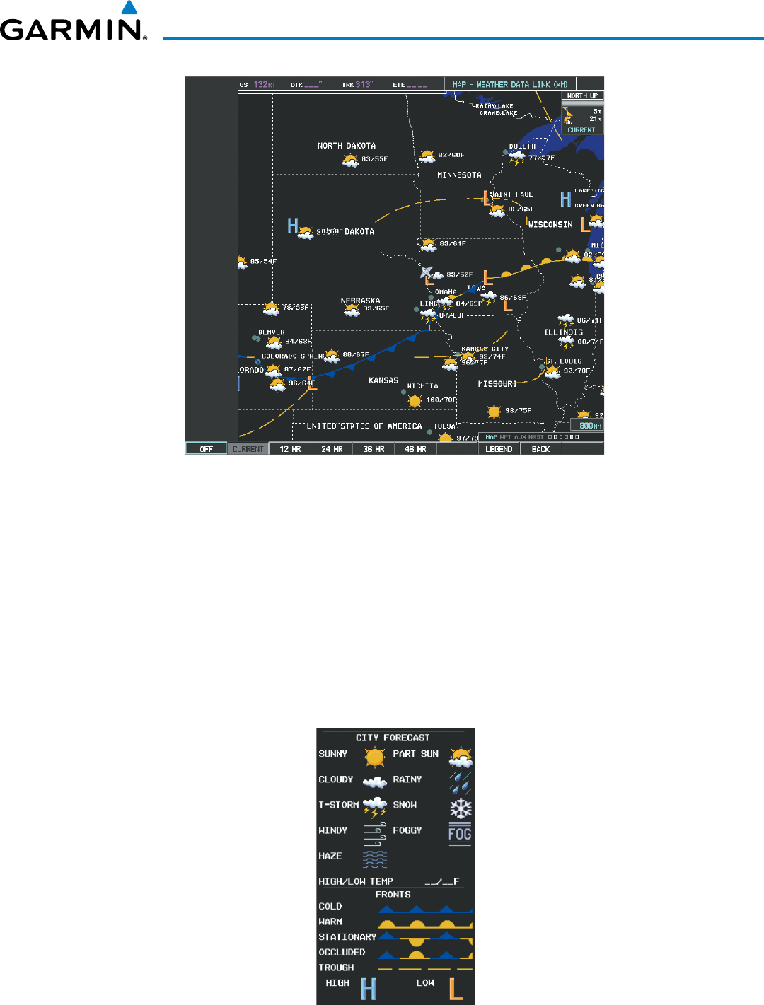
190-00928-04 Rev. A
Garmin G1000 Pilot’s Guide for the Beechcraft 200/B200 Series
335
HAZARD AVOIDANCE
Figure 6-28 Surface Analysis Data - 24-Hour
Displaying Surface Analysis and City Forecast information:
1) Select the Weather Data Link (XM) Page.
2) Select the MORE WX Softkey.
3) Select the SFC Softkey.
4) Select the desired forecast time: CURRENT, 12 HR, 24 HR, 36 HR, or 48 HR. The SFC Softkey label changes
to reflect the forecast time selected.
To display the Surface Analysis and City Forecast legend (Figure 6-29), select the
LEGEND
Softkey when
Surface Analysis and City Forecast are selected to be displayed.
Figure 6-29 Surface Analysis Legend
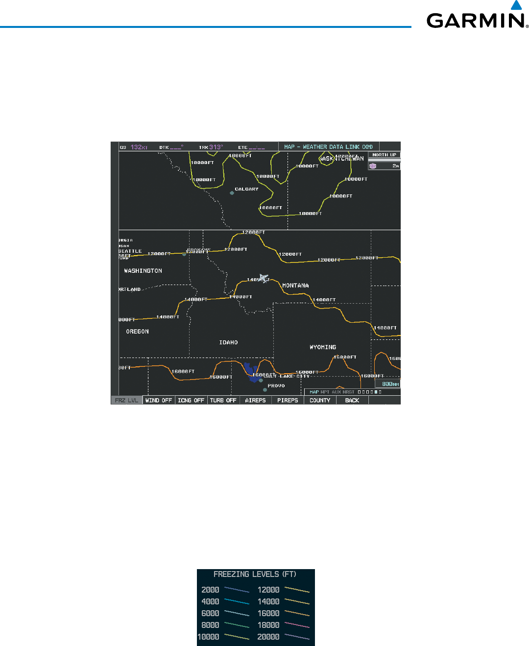
Garmin G1000 Pilot’s Guide for the Beechcraft 200/B200 Series
190-00928-04 Rev. A336
HAZARD AVOIDANCE
FREEZING LEVEL
The Freezing Level weather product (Figure 6-30) shows the color-coded contour lines for the altitude and
location at which the first isotherm is found. When no data is displayed for a given altitude, the data for that
altitude has not been received, or is out of date and has been removed from the display. New data appears
when it becomes available.
Figure 6-30 Freezing Level Data
Displaying Freezing Level information:
1) Select the Weather Data Link (XM) Page.
2) Select the MORE WX Softkey.
3) Select the FRZ LVL Softkey.
To display the Freezing Level legend (Figure 6-31), select the
LEGEND
Softkey when Freezing Level data is
selected to be displayed.
Figure 6-31 Freezing Level Legend
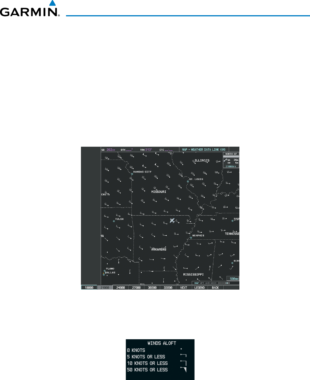
190-00928-04 Rev. A
Garmin G1000 Pilot’s Guide for the Beechcraft 200/B200 Series
337
HAZARD AVOIDANCE
WINDS ALOFT
The Winds Aloft weather product (Figure 6-32) shows the forecast wind speed and direction at the surface
and at selected altitudes. Altitude can be displayed in 3000-foot increments beginning at the surface up to
42,000 feet MSL.
Displaying the Winds Aloft weather product:
1) Select the Weather Data Link (XM) Page with the
FMS
Knob.
2) Select the
MORE WX
Softkey.
3) Select the
WIND
Softkey.
4) Select the desired altitude level: SFC (surface) up to 42,000 feet. Select the
NEXT
or
PREV
Softkey to cycle
through the altitude softkeys. The
WIND
Softkey label changes to reflect the altitude selected.
Figure 6-32 Winds Aloft at 21,000 Feet
To display the Winds Aloft legend (Figure 6-33), select the LEGEND Softkey when Winds Aloft is
selected for display.
Figure 6-33 Winds Aloft Data with Legend
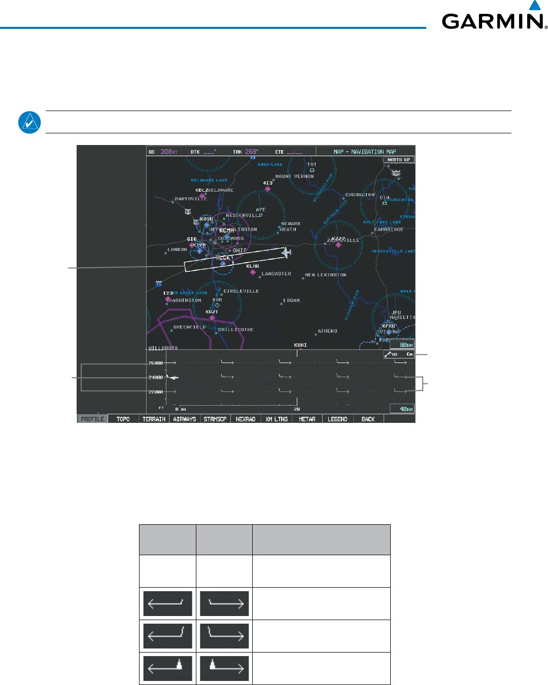
Garmin G1000 Pilot’s Guide for the Beechcraft 200/B200 Series
190-00928-04 Rev. A338
HAZARD AVOIDANCE
Headwind and tailwind components aloft are available inside the Profile View on the Navigation Map Page
(Figure 6-34). The displayed components are relative to current aircraft altitude and track, but not to aircraft
speed.
NOTE: Profile View is not available in TAWS-A installations.
Figure 6-34 Navigation Map Page with Winds Aloft Data on
Profile View
Wind Component
Velocity and Direction
Arrows
Winds Aloft Data Age
Altitude Scale
Profile View
Path Enabled
Arrows pointing to the left indicate headwind components; tailwind component arrows point to the right,
as shown in Table 6-3.
Headwind
Symbol
Tailwind
Symbol
Headwind/Tailwind
Component
None None Less than 5 knots
5 knots
10 knots
50 knots
Table 6-3 Profile View Headwind/Tailwind Component Symbols
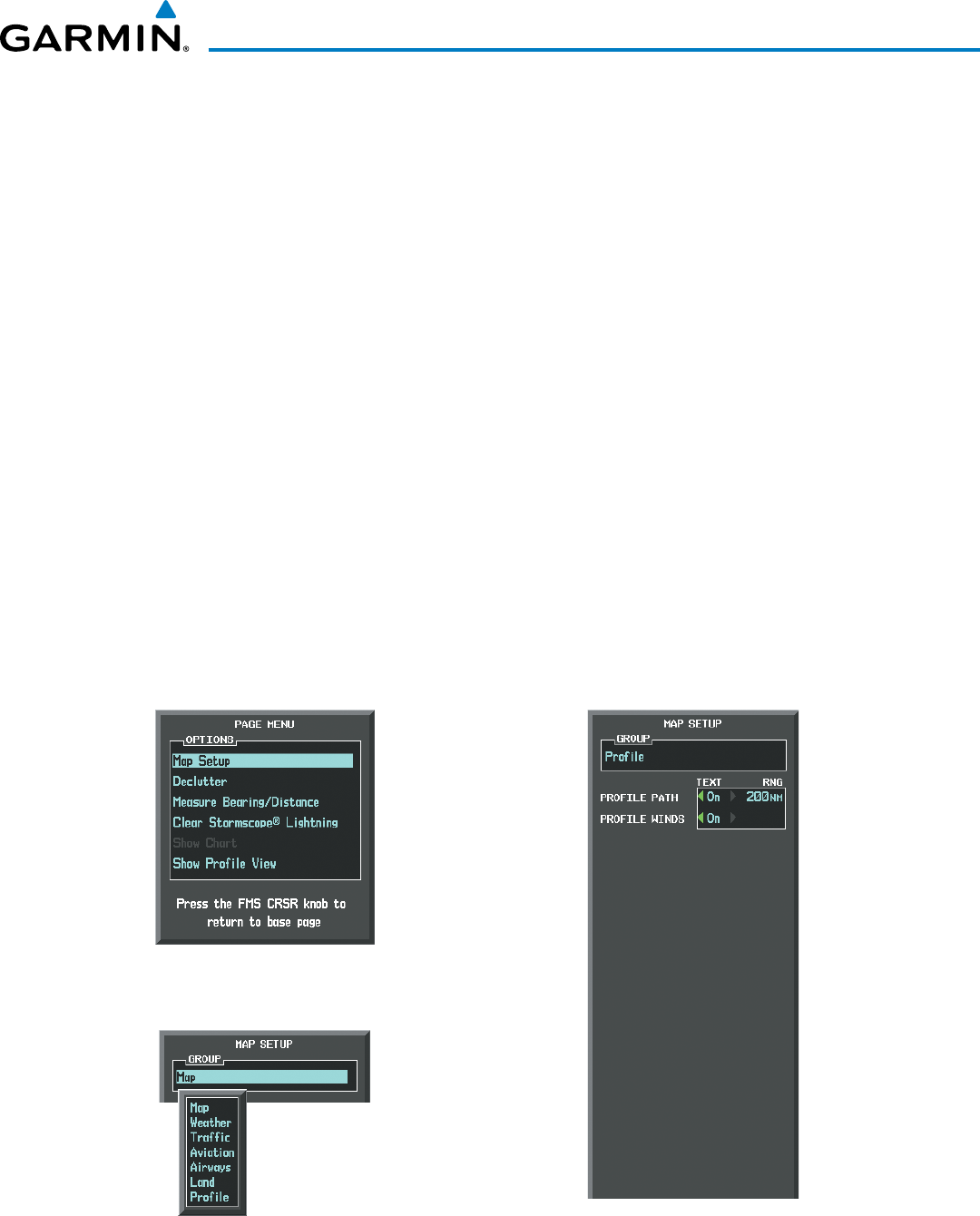
190-00928-04 Rev. A
Garmin G1000 Pilot’s Guide for the Beechcraft 200/B200 Series
339
HAZARD AVOIDANCE
Showing/Hiding Profile View (containing winds aloft data)
1) Select the Navigation Map Page.
2) Select the PROFILE Softkey.
Or:
1) Press the MENU Key.
2) Turn the large FMS Knob to highlight ‘Show Profile View’ or ‘Hide Profile View’ (choice dependent on current
state) and press the
ENT
Key.
Winds Aloft data inside the Profile View is enabled by default when the Profile View is displayed on the
Navigation Map Page. This behavior can be changed on the Navigation Map Page.
Enabling/disabling winds aloft data display in Profile View:
1) Select the Navigation Map Page.
2) Press the MENU Key.
3) With Map Setup highlighted, press the
ENT
Key (Figure 6-35).
4) Turn the small FMS Knob to select the Profile Group and press the ENT Key (Figure 6-36).
5) Turn the large
FMS
Knob to select ‘Profile Winds’ (Figure 6-37).
6) Turn the small
FMS
Knob to select ‘On’ or ‘Off’.
7) Press the FMS Knob or CLR Key to return to the Navigation Map Page with the changed settings.
Figure 6-36 Navigation Map Page Setup Menu
Figure 6-35 Navigation Map Page Menu
Figure 6-37 Navigation Map Page Setup Menu, Weather Group
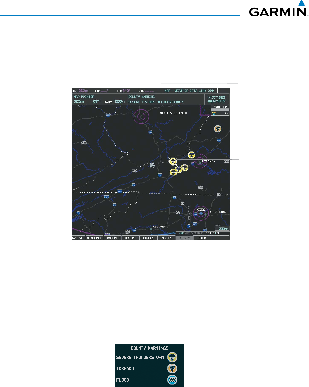
Garmin G1000 Pilot’s Guide for the Beechcraft 200/B200 Series
190-00928-04 Rev. A340
HAZARD AVOIDANCE
COUNTY WARNINGS
The County warning weather product (Figure 6-38) provides specific public awareness and protection
weather warnings from the National Weather Service (NWS). This can include information on tornadoes,
severe thunderstorms, and flood conditions.
Figure 6-38 County Flood and Severe Weather Warnings
Tornado
Warning
Severe
Thunderstorm
Warning
Selected
Additional
Information
on Warning
Selected with
Map Pointer
Displaying County Warning information:
1) Select the Weather Data Link (XM) Page with the
FMS
Knob.
2) Select the MORE WX Softkey.
3) Select the COUNTY Softkey.
To display the County Warnings legend (Figure 6-39), select the LEGEND Softkey when County Warnings
are selected to be displayed.
Figure 6-39 County Warnings Legend
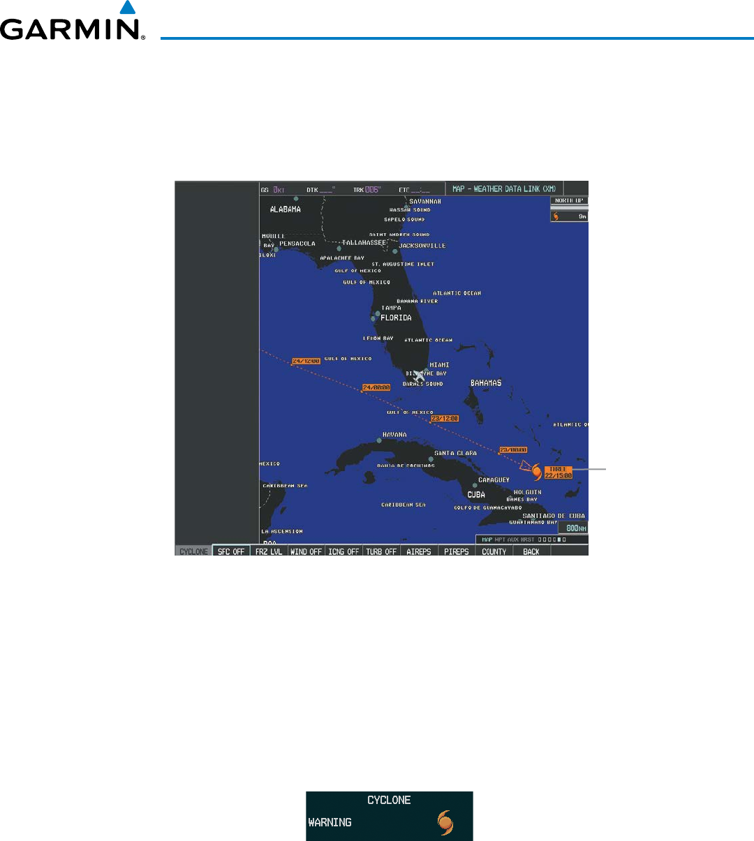
190-00928-04 Rev. A
Garmin G1000 Pilot’s Guide for the Beechcraft 200/B200 Series
341
HAZARD AVOIDANCE
CYCLONE
The Cyclone weather product (Figure 6-40) shows the current location of cyclones (hurricanes), tropical
storms, and their projected tracks. The system displays the projected track information in the form of
DD/HH:MM.
Figure 6-40 Cyclone Data Selected for Display
Cyclone
Displaying cyclone (hurricane) track information:
1) Select the Weather Data Link (XM) Page with the
FMS
Knob.
2) Select the MORE WX Softkey.
3) Select the CYCLONE Softkey.
To display the Cyclone legend (Figure 6-41), select the LEGEND Softkey when Cyclones are selected to
be displayed.
Figure 6-41 Cyclone Legend
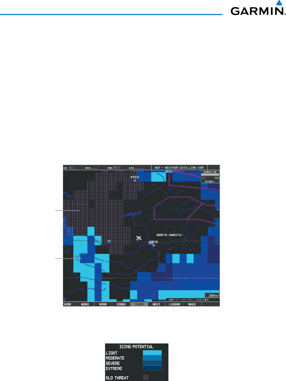
Garmin G1000 Pilot’s Guide for the Beechcraft 200/B200 Series
190-00928-04 Rev. A342
HAZARD AVOIDANCE
ICING (CIP & SLD)
The Current Icing Product (CIP) weather product (Figure 6-42) shows a graphical view of the current icing
environment. Icing severity is displayed in four categories: light, moderate, severe, and extreme (not specific
to aircraft type). The CIP product is not a forecast, but a presentation of the current conditions at the time
of the analysis.
Supercooled Large Droplet (SLD) icing conditions are characterized by the presence of relatively large,
super cooled water droplets indicative of freezing drizzle and freezing rain aloft. SLD threat areas are depicted
as magenta dots over the CIP colors.
Displaying Icing data:
1) Select the Weather Data Link (XM) Page.
2) Select the
MORE WX
Softkey.
3) Select the
ICNG
Softkey.
4) Select the desired altitude level: 1,000 feet up to 30,000 feet. Select the
NEXT
or
PREV
Softkey to cycle through
the altitude softkeys. The
ICNG
Softkey label changes to indicate the altitude selected.
Figure 6-42 Icing Data at 15,000 Feet
Supercooled
Large Droplet
Threat
Icing
To display the Icing Potential legend (Figure 6-43), select the
LEGEND
Softkey when Icing is selected for
display.
Figure 6-43 Icing Potential Legend
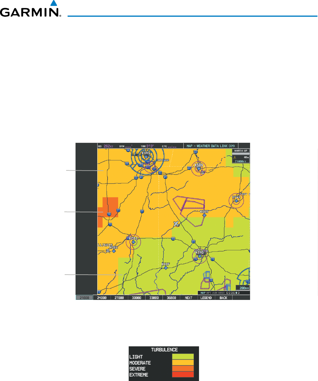
190-00928-04 Rev. A
Garmin G1000 Pilot’s Guide for the Beechcraft 200/B200 Series
343
HAZARD AVOIDANCE
TURBULENCE
The Turbulence weather product (Figure 6-44) identifies the potential for erratic movement of high-altitude
air mass associated winds. Turbulence is classified as light, moderate, severe or extreme, at altitudes between
21,000 and 45,000 feet. Turbulence information is intended to supplement AIRMETs, SIGMETs, and PIREPs.
Displaying Turbulence data:
1) Select the Weather Data Link (XM) Page.
2) Select the
MORE WX
Softkey.
3) Select the
TURB
Softkey.
4) Select the desired altitude level: 21,000 feet up to 45,000 feet. Selects the
NEXT
or
PREV
Softkey to cycle
through the altitude softkeys. The
TURB
Softkey label changes to indicate the altitude selected.
Figure 6-44 Turbulence Data at 21,000 Feet
Severe
Turbulence
Moderate
Turbulence
Light
Turbulence
To display the Turbulence legend (Figure 6-45), select the
LEGEND
Softkey when Turbulence is enabled
for display.
Figure 6-45 Turbulence Legend
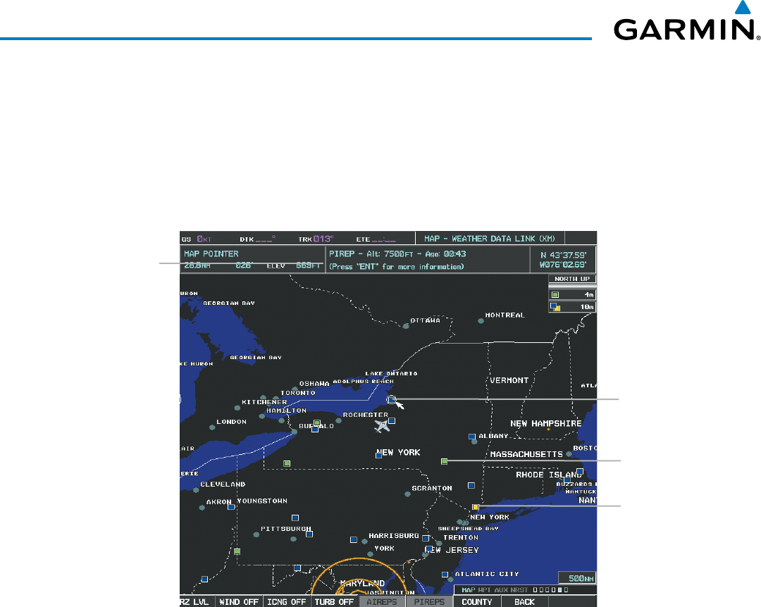
Garmin G1000 Pilot’s Guide for the Beechcraft 200/B200 Series
190-00928-04 Rev. A344
HAZARD AVOIDANCE
PIREPS AND AIREPS
Pilot Weather Reports (PIREPs) (Figure 6-46) are in-flight weather observations collected from pilots.
When significant weather conditions are reported or forecast, Air Traffic Control (ATC) facilities are required
to solicit PIREPs. A PIREP may contain adverse weather conditions, such as low in-flight visibility, icing
conditions, wind shear, and turbulence. PIREPs are issued as either Routine (UA) or Urgent (UUA).
Another type of PIREP is an Air Report (AIREP). Commercial airlines typically generate AIREPs.
Figure 6-46 AIREPs and PIREPs on the Weather Data Link (XM) Page
Instructions for
Viewing PIREP
and AIREP Text
PIREP
Selected
Urgent
PIREP
AIREP
Displaying PIREP and AIREP text:
1) Select the Weather Data Link (XM) Page.
2) Select the
MORE WX
Softkey.
3) Select the
AIREPS
or
PIREPS
Softkey.
4) Press the RANGE Knob and pan to the desired weather report. A gray circle will appear around the weather
report when it is selected.
5) Press the ENT Key. The Weather Information Page is shown with PIREP or AIREP text. The data is first displayed
in a decoded fashion, then as raw text.
6) Use the FMS Knob or the ENT Key to scroll through the PIREP or AIREP text.
7) Press the FMS Knob or the CLR Key to return to the Weather Data Link (XM) Page.
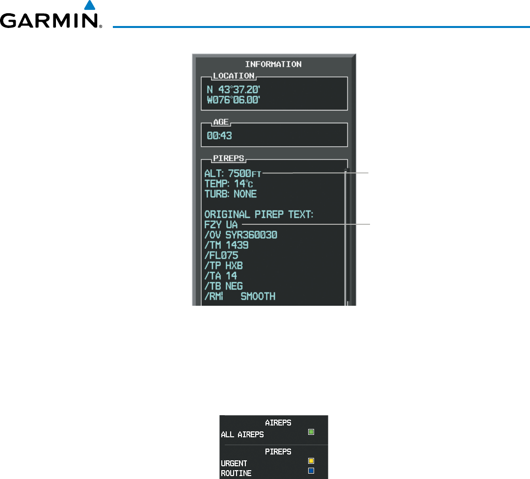
190-00928-04 Rev. A
Garmin G1000 Pilot’s Guide for the Beechcraft 200/B200 Series
345
HAZARD AVOIDANCE
Figure 6-47 PIREP Text on the Weather
Data Link (XM) Page
Decoded PIREP Text
Original PIREP Text
To display the PIREP or AIREP legend (Figure 6-48), select the
LEGEND
Softkey when PIREPs or AIREPs
are selected for display.
The PIREP color is determined by the type (routine or urgent).
Figure 6-48 AIREPs & PIREPs Legend
TFRS
In the United States, the FAA issues Temporary Flight Restrictions (TFRs) to designate areas where flight is
restricted. TFRs are issued to restrict flight for a variety of reasons including national security, law enforcement,
natural disasters, and large sporting events. TFRs may be issued at any time, and TFR data displayed on the
G1000 is only intended to supplement official TFR information obtained from Flight Service Stations (FSS),
and air traffic control.
The age of TFR data is not shown; however, if TFR data is not available or has expired, the system displays
‘TFR N/A’ in the upper-left corner of maps on which TFRs can be displayed.
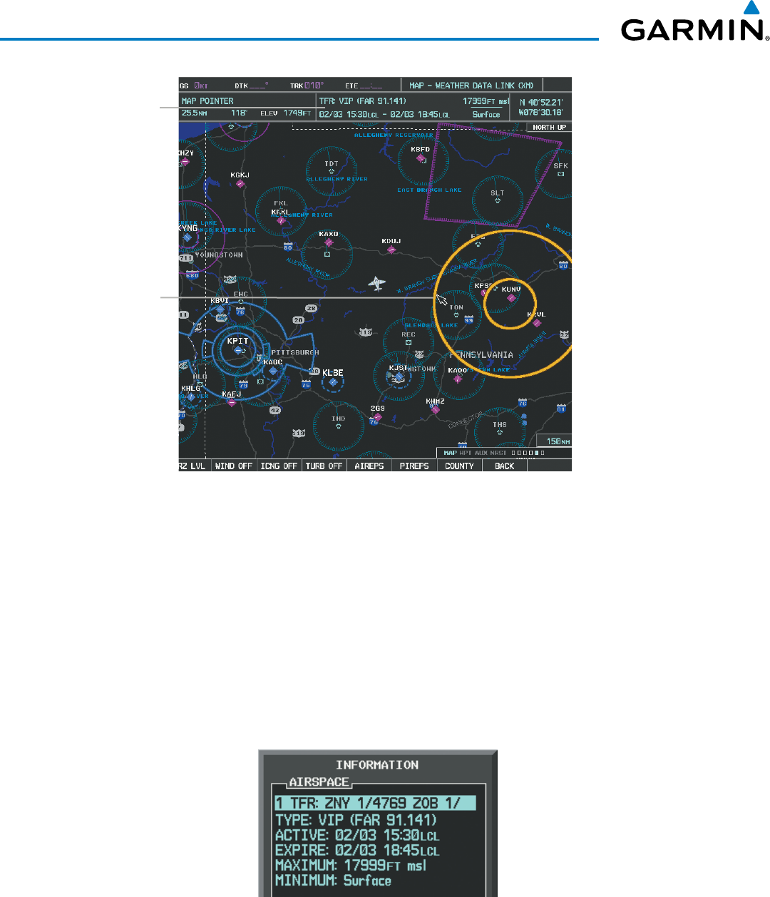
Garmin G1000 Pilot’s Guide for the Beechcraft 200/B200 Series
190-00928-04 Rev. A346
HAZARD AVOIDANCE
Figure 6-49 TFR Data on the Weather Data Link (XM) Page
TFR Summary
Data
TFR
Selected
with Map
Pointer
Displaying TFR Data:
1) Select the Weather Data Link (XM) Page or Navigation Map Page.
2) Press the RANGE Knob and pan the map pointer over a TFR to highlight it. The system displays TFR summary
information above the map.
3) Press the ENT Key. The system displays a pop-up menu.
4) If necessary, turn the FMS Knob to select ‘Review Airspaces’ and press the ENT Key. The system displays the
TFR Information window.
5) Press the FMS Knob or the CLR Key to remove the TFR Information window.
Figure 6-50 Full Text for Selected TFR
The setup menus for the Navigation Map Page control the map range settings above which TFR data is
decluttered from the display. If a map range larger than the TFR product map range setting is selected, the TFR
product data is removed from the map.
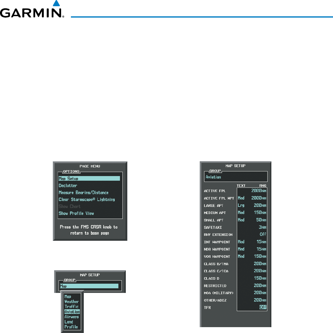
190-00928-04 Rev. A
Garmin G1000 Pilot’s Guide for the Beechcraft 200/B200 Series
347
HAZARD AVOIDANCE
Maps other than the Navigation Map Page use settings based on those selected for the Navigation Map Page.
Setting up and customizing TFR data for maps on which TFR data can be displayed:
1) Select the Navigation Map Page.
2) Press the MENU Key.
3) With Map Setup highlighted, press the
ENT
Key (Figure 6-51).
4) Turn the small FMS Knob to select the Aviation Group and press the ENT Key (Figure 6-52).
5) Turn the large
FMS
Knob to scroll to the TFR product range setting (Figure 6-53).
6) Turn the small
FMS
Knob to scroll through options (Off, range settings).
7) Press the
ENT
Key to select an option.
8) Press the FMS Knob or CLR Key to return to the Navigation Map Page with the changed settings.
Figure 6-52 Navigation Map Page Setup Menu
Figure 6-51 Navigation Map Page Menu
Figure 6-53 Navigation Map Page Setup Menu, Weather Group
Garmin G1000 Pilot’s Guide for the Beechcraft 200/B200 Series
190-00928-04 Rev. A348
HAZARD AVOIDANCE
6.2 GARMIN CONNEXT WEATHER
WARNING: Do not use data link weather information for maneuvering in, near, or around areas of hazardous
weather. Information contained within data link weather products may not accurately depict current
weather conditions.
WARNING: Do not use the indicated data link weather product age to determine the age of the weather
information shown by the data link weather product. Due to time delays inherent in gathering and processing
weather data for data link transmission, the weather information shown by the data link weather product
may be significantly older than the indicated weather product age.
NOTE: The availability of specific Garmin Connext weather products varies by region and is subject to
change. For weather product coverage information, refer to fly.garmin.com/fly-garmin/gfds-weather. This
Pilot’s Guide shows all Garmin Connext Weather products, regardless of product availability in a specific
area.
The optional GSR 56 Iridium satellite data link receiver provides extensive weather information to the G1000.
The system displays graphical weather information and its associated text on the Multi Function Display (MFD)
and the Primary Flight Display (PFD) Inset Map.
The system provides weather information after the flight crew selects either a manual or automatic Connext
Data Request on the Weather Data Link (CNXT) Page on the MFD.
Garmin Connext Weather requires an active subscription to both Iridium and Garmin Connext services. Refer
to the Additional Features section for information on registering for Garmin Connext services.
ACCESSING GARMIN CONNEXT WEATHER PRODUCTS
The principal map for viewing Garmin Connext Weather information is the Weather Data Link (CNXT) Page
in the Map Page Group (Figure 6-54). This is the only map display capable of showing information for all
available Garmin Connext Weather products. No weather data is displayed until the system completes the first
crew-initiated Connext Data Request.
Viewing the Weather Data Link (CNXT) Page:
1) Turn the large
FMS
Knob to select the Map Page Group.
2) Turn the small
FMS
Knob
to select the Weather Data Link (CNXT or XM) Page. If the page title contains
‘XM’, continue with this procedure to change the data link weather source from SiriusXM to Garmin Connxext.
3) Press the Menu Key.
4) If necessary, turn the large FMS Knob to highlight ‘Display Connext Weather’, then press the ENT Key. Page
title displays ‘MAP - WEATHER DATA LINK (CNXT)’.
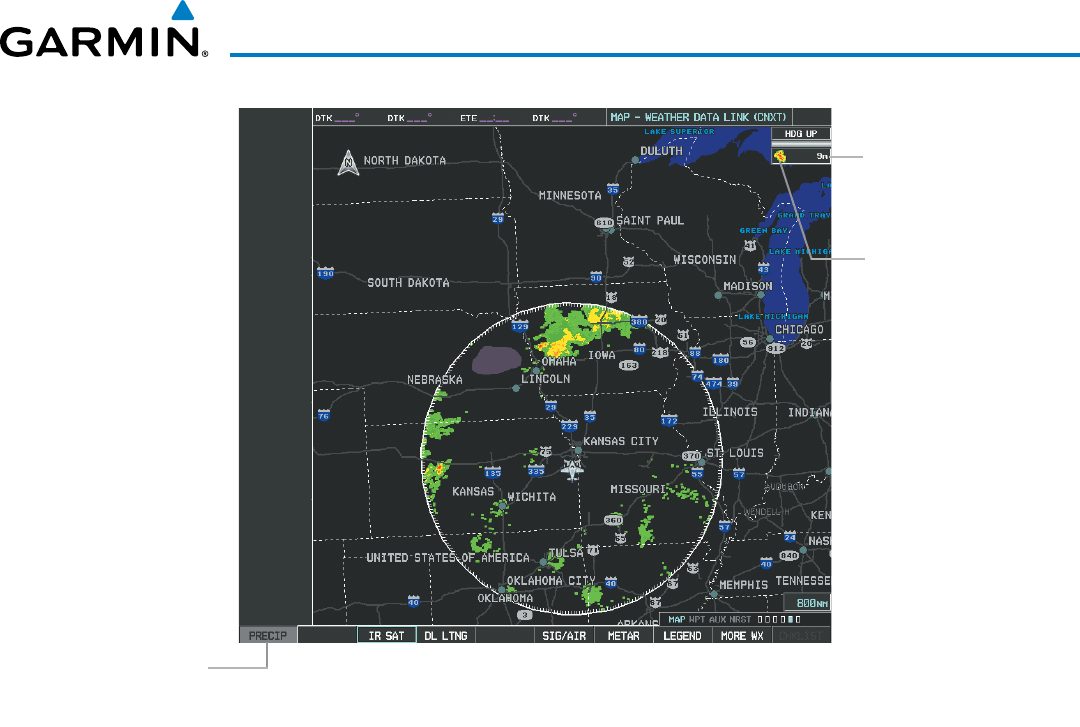
190-00928-04 Rev. A
Garmin G1000 Pilot’s Guide for the Beechcraft 200/B200 Series
349
HAZARD AVOIDANCE
Figure 6-54 Weather Data Link (CNXT) Page (After Connext Data Request)
Weather
product age
information
Precip Weather
Product Display
Enabled Symbol
Precip Weather
Product Selected
for Display
When a weather product is selected for display on the Weather Data Link (CNXT) Page, a box containing a
symbol for the product and its age (in minutes) are shown in the upper right (Figure 6-54). If weather data has
not been requested yet or is not available, ‘N/A’ is shown next to the product symbol instead of age. The age of
the weather product is based on the time difference between when the data was assembled on the ground and
the current GPS time.
Weather products are updated continuously or refreshed at specific intervals (defined in the Refresh Rate
column in Table 6-4).
If for any reason, a weather product is not refreshed within the defined Expiration Time intervals (see Table
6-4), the data is considered expired and is removed from the display. The age of the expired product is replaced
by dashes. If more than half of the expiration time has elapsed, the color of the product age changes to yellow.
As an additional reference, the Garmin Connext Weather product symbol and age can be enabled/disabled
for display on the PFD Inset Map.
Enabling/Disabling XM WX Product Information on the PFD Inset Map:
1) Press the INSET Softkey.
2) Press the WX LGND Softkey to display or remove product symbol and age data when a Garmin Connext
Weather product is selected for display on the PFD Inset Map.
Table 6-4 shows the Garmin Connext Weather product symbols, the expiration time and the refresh rates.
The refresh rate represents the interval at which the Garmin Connext ground-based infrastructure makes
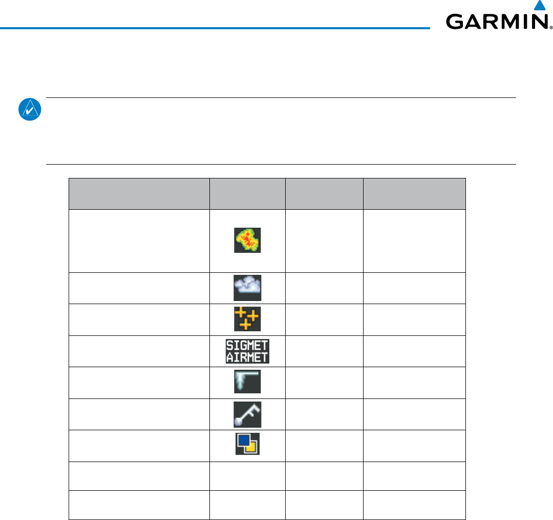
Garmin G1000 Pilot’s Guide for the Beechcraft 200/B200 Series
190-00928-04 Rev. A350
HAZARD AVOIDANCE
available the most current known weather data. It does not necessarily represent the rate at which new content
is received from weather sources.
NOTE: The availability of specific Garmin Connext Weather products varies by region and is subject to
change. For weather product coverage information, refer to fly.garmin.com/fly-garmin/gfds-weather. This
Pilot’s Guide shows all Garmin Connext Weather products, regardless of product availability in a specific
area.
Garmin Connext Weather
Product Symbol Expiration Time
(Minutes)
Refresh Rate
(Minutes)
Radar Precipitation
(PRECIP) 30
U.S.: 3*
Canada: 3*
†
Europe: 15
Australia: 15ˆ
Infrared Satellite
(IR SAT) 60 30
Datalink Lightning
(DL LTNG) 30 Continuous
SIGMETs/AIRMETs
(SIG/AIR) 60 Continuous
Meteorological Aerodrome Report
(METARs) 90 Continuous
Winds Aloft
(WIND) 90 Continuous
Pilot Weather Report
(PIREPs) 90 Continuous
Temporary Flight Restrictions
(TFRs) no product image 60 Continuous
Terminal Aerodrome Reports
(TAFs) no product image 60 Continuous
* The composite precipitation image is updated every 3 minutes, but individual radar sites may take
between 3 and 10 minutes to provide new data.
†
Canadian radar precipitation data provided by Environment Canada.
ˆ Australian radar precipitation data provided by the Australian Bureau of Meteorology.
Table 6-4 Garmin Connext Weather Product Symbols and Data Timing
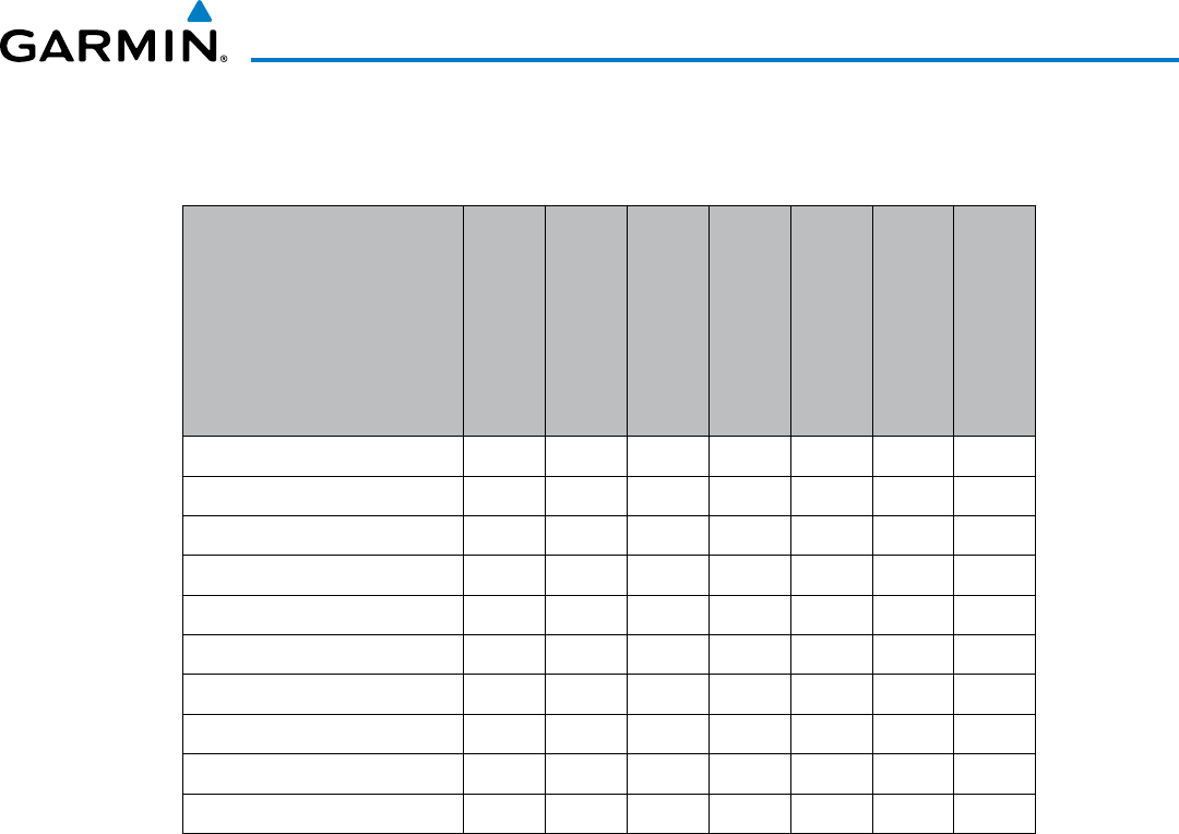
190-00928-04 Rev. A
Garmin G1000 Pilot’s Guide for the Beechcraft 200/B200 Series
351
HAZARD AVOIDANCE
Table 6-5 shows which Garmin Connext Weather products can be displayed (indicated with a ‘+’ symbol) on
specific G1000 maps.
Garmin Connext Weather
Product
PFD Inset Map
Navigation Map Page
Weather Data Link
CNXT) Page
Weather Information
Page
AUX - Trip Planning
Page
Nearest Page Group
Flight Plan Pages
Precipitation (PRECIP) + + + + + +
Infrared Satellite (IR SAT) +
Datalink Lightning (LTNG) + + + + + +
SIGMETs/AIRMETs (SIG/AIR) +
METARs + + + + + + +
Winds Aloft (WIND) +* +
PIREPs + +
Radar Coverage + + +
TFRs + + + + + + +
TAFs + +
* Winds Aloft data is available inside Profile View when Profile View is enabled on the Navigation
Map Page (TAWS-B installations only).
Table 6-5 Garmin Connext Weather Product Display Maps
Softkeys control the display of weather information on most MFD pages and the PFD Inset Map. Figure
6-55 shows the weather product softkeys for the Weather Data Link (CNXT) Page. When a weather product
is selected for display, the corresponding softkey label changes to gray to indicate the product display is
enabled.
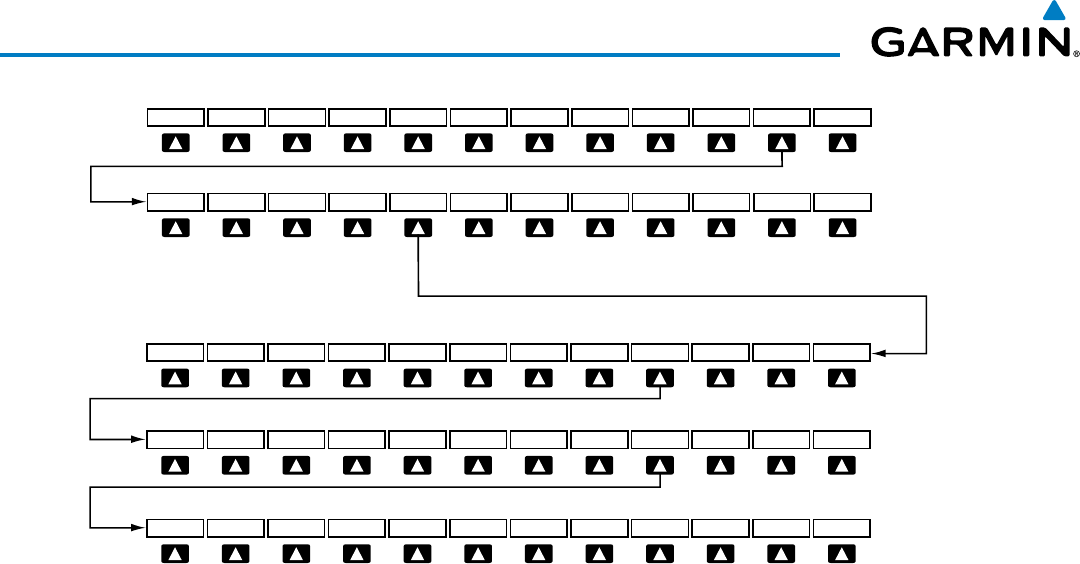
Garmin G1000 Pilot’s Guide for the Beechcraft 200/B200 Series
190-00928-04 Rev. A352
HAZARD AVOIDANCE
Figure 6-55 Weather Data Link (CNXT) Page Softkeys (MFD)
Press the BACK Softkey
to move up one level.
BACK
PRECIP MORE WX
DL LTNGIR SAT SIG/AIR METAR
LEGEND
CHKLIST
9000
120006000 BACK
LEGEND
3000
15000
SFC
PREV OFF NEXT
27000
3000024000BACK
LEGEND
21000
18000
PREV OFF NEXT
42000BACK
LEGEND
39000
36000
PREV OFF NEXT
WIND Softkey label changes
to reflect current selection.
PREV and NEXT Softkeys cycle through Winds Aloft
altitude selection softkeys.
WIND OFF
PIREPS
33000
The setup menus for the Navigation Map Page and the Weather Data Link (CNXT) Page control the map range
settings above which weather products data are decluttered from the display. If a map range larger than the
weather product map range setting is selected, the weather product data is removed from the map. The menus
also provide a means in addition to the softkeys for enabling/disabling display of weather products.
Setting up and customizing the Weather Data Link (CNXT) Page:
1) Select the Weather Data Link (CNXT) Page.
2) Press the
MENU
Key.
3) With ‘Weather Setup’ highlighted, press the
ENT
Key (Figure 6-56).
4) Turn the small
FMS
Knob to select ‘PRODUCT GROUP 1’ or ‘PRODUCT GROUP 2’, and press the
ENT
Key (Figure
6-57).
5) Turn the large
FMS
Knob or press the
ENT
Key to scroll through product selections.
6) Turn the small
FMS
Knob to scroll through options for each product (ON/OFF, maximum range settings, etc.).
7) Press the
ENT
Key to select an option.
8) Press the FMS Knob or CLR Key to return to the Weather Data Link (CNXT) Page with the changed settings.
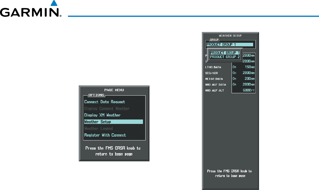
190-00928-04 Rev. A
Garmin G1000 Pilot’s Guide for the Beechcraft 200/B200 Series
353
HAZARD AVOIDANCE
Figure 6-57 Weather Data Link
(CNXT) Page Setup Menu
Figure 6-56 Weather Data Link (CNXT) Page Menu
Restoring default Weather Data Link (CNXT) Page settings:
1) Select the Weather Data Link (CNXT) Page.
2) Press the MENU Key.
3) With ‘Weather Setup’ highlighted, press the
ENT
Key.
4) Press the
MENU
Key.
5) Highlight the desired default(s) to restore (all or for selection) and press ENT Key.
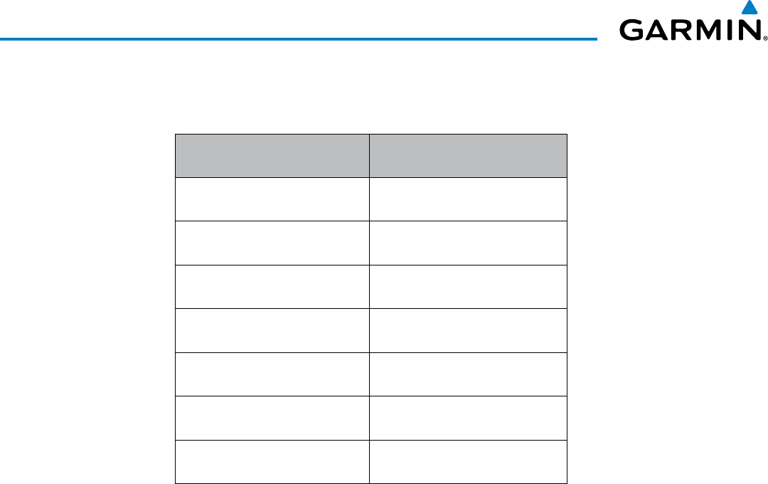
Garmin G1000 Pilot’s Guide for the Beechcraft 200/B200 Series
190-00928-04 Rev. A354
HAZARD AVOIDANCE
If both Garmin Connext Weather and SiriusXM weather services are installed, customizing the display settings
for the corresponding weather products shown in Table 6-6 will result in identical settings for both services.
SiriusXM Weather Product Garmin Connext Weather
Product
Next-generation Radar
(NEXRAD)
Precipitation
(PRECIP)
Cloud Top
(CLD TOP)
Infrared Satellite
(IR SAT)
SiriusXM Lightning
(XM LTNG)
Data Link Lightning
(DL LTNG)
SIGMETs/AIRMETs
(SIG/AIR)
SIGMETs/AIRMETs
(SIG/AIR)
Meteorological Aerodrome Report
(METARs)
Meteorological Aerodrome Report
(METARs)
Winds Aloft
(WIND)
Winds Aloft
(WIND)
Pilot Weather Report
(PIREPs)
Pilot Weather Report
(PIREPs)
Table 6-6 Corresponding SiriusXM and Garmin Connext Weather
Products
Maps besides the Weather Data Link (CNXT) Page use settings based on those selected for the Navigation
Map Page.
Setting up and customizing weather data for the Navigation Map Page:
1) Select the Navigation Map Page.
2) Press the MENU Key.
3) With ‘Map Setup’ highlighted, press the
ENT
Key (Figure 6-58).
4) Turn the small FMS Knob to select the ‘Weather’ Group and press the ENT Key (Figure 6-59).
5) Turn the large
FMS
Knob or press the
ENT
Key to scroll through product selections (Figure 6-60).
6) Turn the small
FMS
Knob to scroll through options for each product (ON/OFF, range settings).
7) Press the
ENT
Key to select an option.
8) Press the FMS Knob or CLR Key to return to the Navigation Map Page with the changed settings.
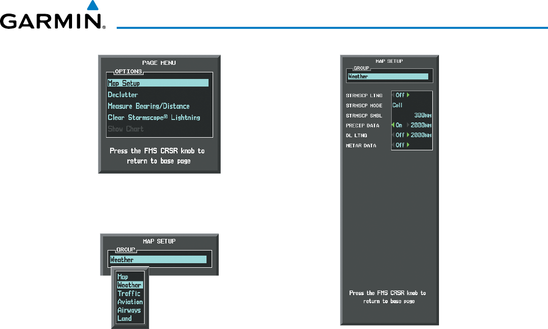
190-00928-04 Rev. A
Garmin G1000 Pilot’s Guide for the Beechcraft 200/B200 Series
355
HAZARD AVOIDANCE
Figure 6-59 Navigation Map Page Setup Menu
Figure 6-58 Navigation Map Page Menu
Figure 6-60 Navigation Map Page Setup Menu, Weather Group
Each active weather product has an associated legend which can be displayed on the Weather Data Link
(CNXT) Page. If no weather product softkeys are selected, the LEGEND Softkey will be unavailable.
Viewing legends for displayed weather products on the Weather Data Link (CNXT) Page:
1) Select the Weather Data Link (CNXT) Page.
2) Select the LEGEND Softkey to display the legends for the displayed weather products.
Or:
a) Press the MENU Key.
b) Select ‘Weather Legend’ and press the ENT Key.
3) Turn the FMS Knob to scroll through the legends if more are available than fit in the window.
4) To remove the Legend Window, select the LEGEND Softkey, the ENT or the CLR Key, or press the FMS Knob.
Additional information about the following can be displayed by panning over the display on the map:
• Infrared Satellite (IR SAT)
• SIGMETs
• AIRMETs
• METARs
• TFRs
• PIREPs
The map panning feature is enabled by pressing the RANGE Knob. The map range is adjusted by turning
the RANGE Knob. If the map range is adjusted while panning is enabled, the map is re-centered on the Map
Pointer.
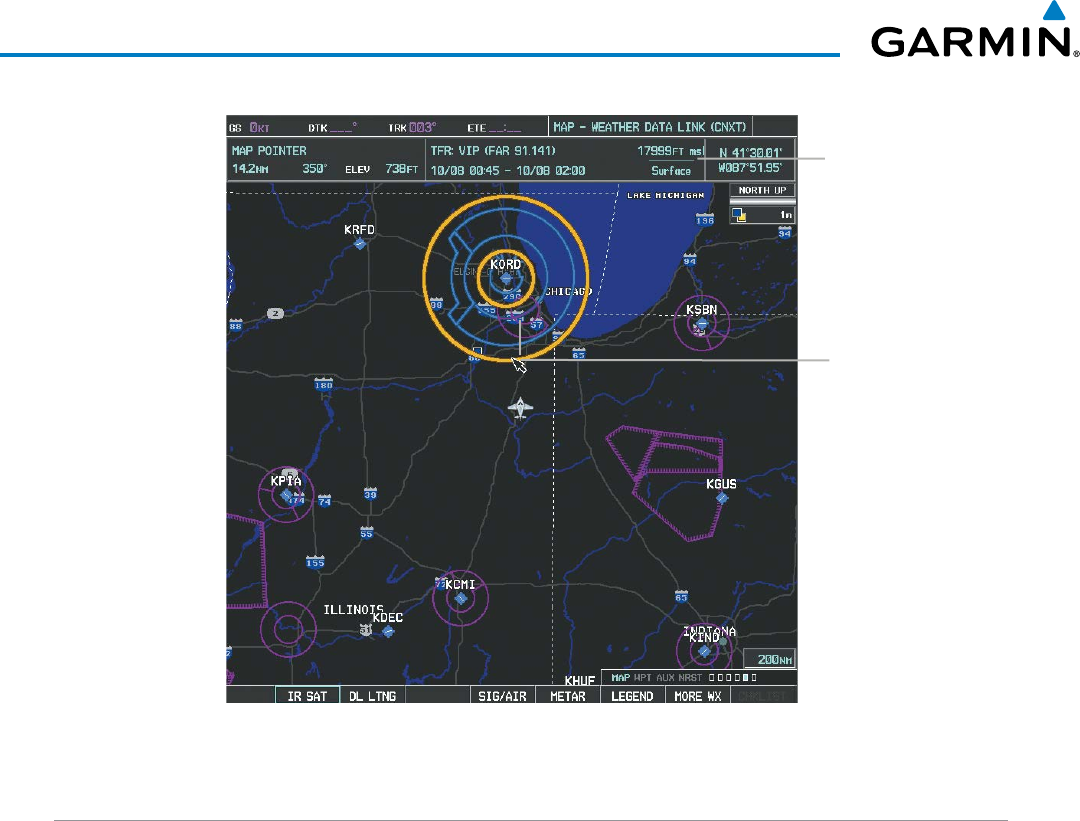
Garmin G1000 Pilot’s Guide for the Beechcraft 200/B200 Series
190-00928-04 Rev. A356
HAZARD AVOIDANCE
Figure 6-61 Panning on the Weather Data Link (CNXT) Page
Additional In-
formation on
TFR Selected
with Map
Pointer
TFR Selected
with Map
Pointer
CONNEXT DATA REQUESTS
The Connext Data Request Menu provides the flight crew with the options to define the requested weather
coverage area(s), choose automatic weather update intervals (if desired), and the ability to send or cancel weather
data requests. A ‘REQUEST STATUS’ window inside the menu shows the status of the Connext Data Request.
Before a Connext Data Request can occur, a valid request coverage area must be defined from which all currently
available Garmin Connext Weather products will be retrieved. At a minimum, either the aircraft’s present position
or a waypoint (as part of a flight plan or entered directly in the ‘WAYPOINT’ coverage field) must be part of
the request coverage area, otherwise the request status window indicates ‘INVALID COVERAGE AREA’ and the
system will not allow a request to occur.
It is not necessary for a destination (based on an active flight plan), a flight plan, or waypoint to be specified
prior to enabling these coverage areas; however no weather data will be retrieved for these option(s) until a flight
plan or waypoint is provided, respectively.
Manually Requesting Garmin Connext Weather information:
1) Select the Weather Data Link (CNXT) Page.
2) Press the MENU Key.
3) With ‘Connext Data Request’ highlighted, press the
ENT
Key (Figure 6-62).
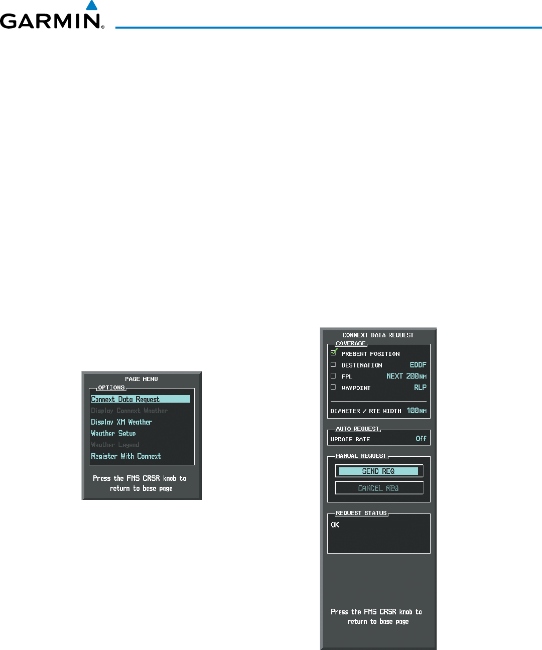
190-00928-04 Rev. A
Garmin G1000 Pilot’s Guide for the Beechcraft 200/B200 Series
357
HAZARD AVOIDANCE
4) Turn the large FMS Knob to highlight the desired coverage option(s) and press the
ENT
Key to show or hide a
green check mark to select one of more of the following coverage selections (Figures 6-63, 6-64):
• PRESENT POSITION – Requests data based on current location.
• DESTINATION – Requests data based on the active flight plan destination (Direct-To destinations excluded).
See the Flight Management section for more information about entering and activating flight plans.
• FPL – Requests data along an active flight plan, if one exists. Turn the small FMS Knob to select the desired
flight plan look-ahead distance option (or choose ‘REMAINING FPL’ to request weather data for the remainder
of the flight plan), then press the ENT Key.
• WAYPOINT – Requests data based on a waypoint (which may be off-route). Turn the large and small FMS
Knobs to enter a waypoint, then press the ENT Key.
5) Turn the large FMS Knob highlight to the ‘DIAMETER / RTE WIDTH’ (diameter/route width) distance field and
turn the small FMS Knob to select the desired diameter and route width of the request, then press the
ENT
Key.
6) Turn the large FMS Knob until the ‘SEND REQ’ button is highlighted. Press the
ENT
Key to initiate the request
immediately or press the FMS Knob to return to the Weather Data Link (CNXT) Page without requesting
weather data.
Figure 6-62 Weather Data Link (CNXT)
Page Menu
Figure 6-63 Connext Data Request Window
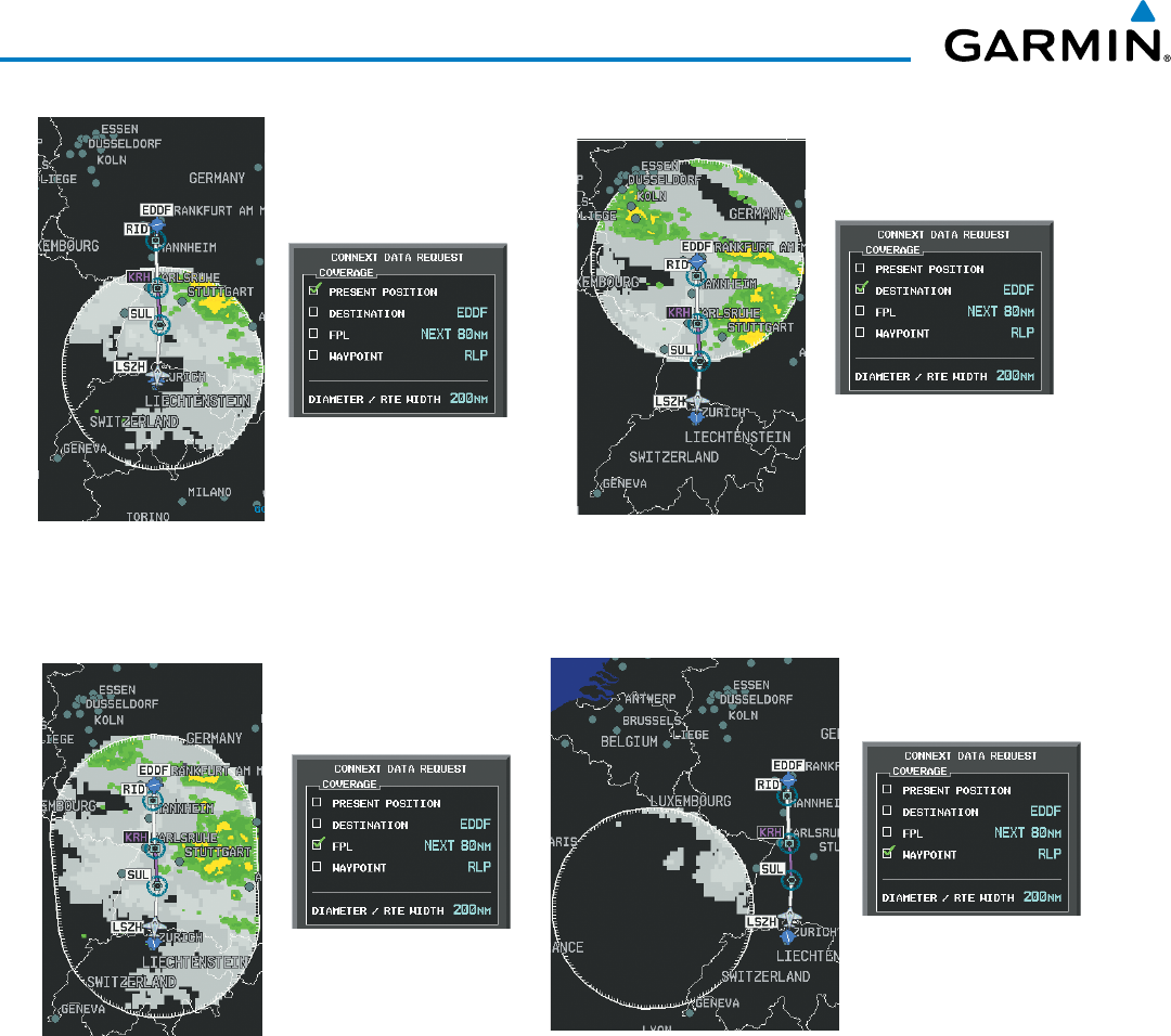
Garmin G1000 Pilot’s Guide for the Beechcraft 200/B200 Series
190-00928-04 Rev. A358
HAZARD AVOIDANCE
Figure 6-64 Garmin Connext Weather Data Request Results with Precipitation Data Displayed
Present Position Selected,
200 nm Diameter
Requested
Destination Selected,
200 nm Diameter
Requested
Next 80 nm of Flight Plan
Selected, 200 nm Route
Width Requested
Off-Route Waypoint
Selected, 200 nm Diameter
Requested
During a Connext Data Request, the REQUEST STATUS Window initially displays “Contacting Connext...”.
Once a connection is established, the REQUEST STATUS Window displays “Receiving Wx Data... Time
Remaining:” with an estimated data transfer time (either minutes or seconds). If desired, the Connext Data
Request Menu may be removed while the data request is processing by pressing the FMS Knob; the data request
will continue to process in the background. Connext Data Requests typically take between 1 to 4 minutes to
complete depending on the size of the selected weather coverage area, the amounts of weather activity present,
and the Iridium signal strength.
The system retrieves all available Garmin Connext Weather products within the selected coverage area during
an initial Connext Data Request, regardless of which products (if any) are currently enabled for display. On
subsequent requests, the system retains previously retrieved textual data (such as METARs and TAFS) if it has
not expired, while new textual weather data matching the current coverage area and all graphical weather data
is transferred to the aircraft during every data request.

190-00928-04 Rev. A
Garmin G1000 Pilot’s Guide for the Beechcraft 200/B200 Series
359
HAZARD AVOIDANCE
At the completion of a successful weather data request, the REQUEST STATUS Window indicates ‘OK’ if the
Connext Data Request menu is still within view.
Cancelling a Connext Data Request in Progress:
1) Select the Weather Data Link (CNXT) Page.
2) Press the
MENU
Key.
3) With ‘Connext Data Request’ highlighted, press the
ENT
Key.
4) Turn the large
FMS
Knob to select ‘CANCEL REQ’ and press the
ENT
Key. The request status box indicates
‘Request Cancelled’.
5) Press the FMS Knob to return to the Weather Data Link (CNXT) Page.
The flight crew can schedule Connext Data Requests to recur automatically. Automatic requests remain
enabled until the flight crew them, or the G1000 power is cycled. The REQUEST STATUS Window will
indicate a countdown timer until the next automatic data request occurs.
NOTE: If automatic Connext Data Requests were enabled prior to the system entering Reversionary Mode,
the automatic weather data requests will continue in Reversionary Mode, however the Connext Data
Request Window and its associated options will not be available in Reversionary Mode.
Enabling/disabling automatic Connext Data Requests:
1) Select the Weather Data Link (CNXT) Page.
2) Press the MENU Key.
3) With ‘Connext Weather Request’ highlighted, press the
ENT
Key.
4) Choose the desired weather coverage options.
5) Turn the large FMS Knob to select the ‘UPDATE RATE’ setting. Then turn the small FMS Knob to highlight the
desired automatic update frequency (OFF, 5 Min, 10 Min, 15 Min, 20 Min, 30 Min, 45 Min, or 60 Min), then
press the ENT Key.
6) The ‘SEND REQ” button is highlighted and a countdown timer is displayed in the ‘REQUEST STATUS’ based
on the currently selected update rate. Press the ENT Key to immediately send an immediate Connext Data
Request.
Or:
Press the FMS Knob to return to the Weather Data Link (CNXT) Page.
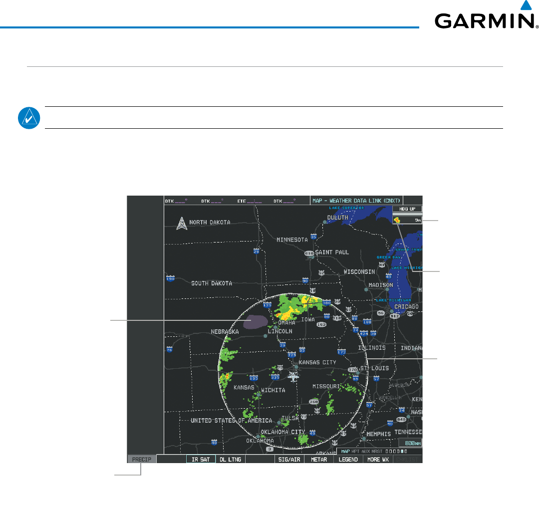
Garmin G1000 Pilot’s Guide for the Beechcraft 200/B200 Series
190-00928-04 Rev. A360
HAZARD AVOIDANCE
GARMIN CONNEXT WEATHER PRODUCTS
PRECIPITATION
NOTE: Precipitation data cannot be displayed at the same time as terrain data.
Precipitation (PRECIP) data is not real-time information. The lapsed time between collection, processing,
and dissemination of radar images can be significant and may not reflect the current radar synopsis. Due to
the inherent delays and the relative age of the data, it should never be used as a basis maneuvering in, near,
or around areas of hazardous weather regardless of the information it contains.
Figure 6-65 Precipitation Data on the Weather Data Link
(CNXT) Page
Weather
product age
information
Precip Weather
Product Display
Enabled icon
Precip Weather
Product Selected
for Display
Boundary of
Precipitation Data
Request
No Radar
Coverage
Shown in Gray
Shade of Purple
Displaying Precipitation weather information:
1) Select the MAP Softkey (for the PFD Inset Map, select the INSET Softkey). This step is not necessary on the
Weather Data Link (CNXT) Page.
2) Select the PRECIP Softkey.
Radar data shown represents highest level, composite reflectivity, of radar returns. The display of the
information is color-coded to indicate the weather severity level. All weather product legends can be viewed
on the Weather Data Link (CNXT) Page. For the Precipitation legend (Figure 6-66), select the
LEGEND
Softkey when Precipitation is selected for display.

190-00928-04 Rev. A
Garmin G1000 Pilot’s Guide for the Beechcraft 200/B200 Series
361
HAZARD AVOIDANCE
No Radar Coverage
Figure 6-66 Precipitation Data Legend
Boundary of weather
data request
The display of radar coverage is enabled active when Precipitation is selected for display. Areas where
precipitation radar coverage is not currently available or is not being collected are indicated in gray shade of
purple. A white boundary line depicting the selected coverage area of the Connext Data Request encloses the
precipitation data when this weather product is displayed.
ReFlectivity
Reflectivity is the amount of transmitted power returned to the radar receiver. Colors on the Precipitation
display directly correlate to the level of detected reflectivity. Reflectivity as it relates to hazardous weather
can be very complex.
The role of radar is essentially to detect moisture in the atmosphere. Simply put, certain types of weather
reflect radar better than others. The intensity of a radar reflection is not necessarily an indication of the
weather hazard level. For instance, wet hail returns a strong radar reflection, while dry hail does not. Both
wet and dry hail can be extremely hazardous.
The different radar echo intensities are measured in decibels (dB) relative to reflectivity (Z). Weather
radars measure the reflectivity ratio, or the energy reflected
back to
the radar receiver (
designated by the
letter Z)
. The value of Z increases as the returned signal strength increases.
PReciPitation liMitationS
Radar images may have certain limitations:
• Radar composite reflectivity does not provide sufficient information to determine precipitation
characteristics (wet hail vs. rain). For example, it is not possible to distinguish between wet snow, wet
hail, and rain.
• An individual radar site cannot depict high altitude storms at close ranges. It has no information about
storms directly over the site.
• When zoomed in to a range of 30 nm, each square block on the display represents an area of four square
kilometers.
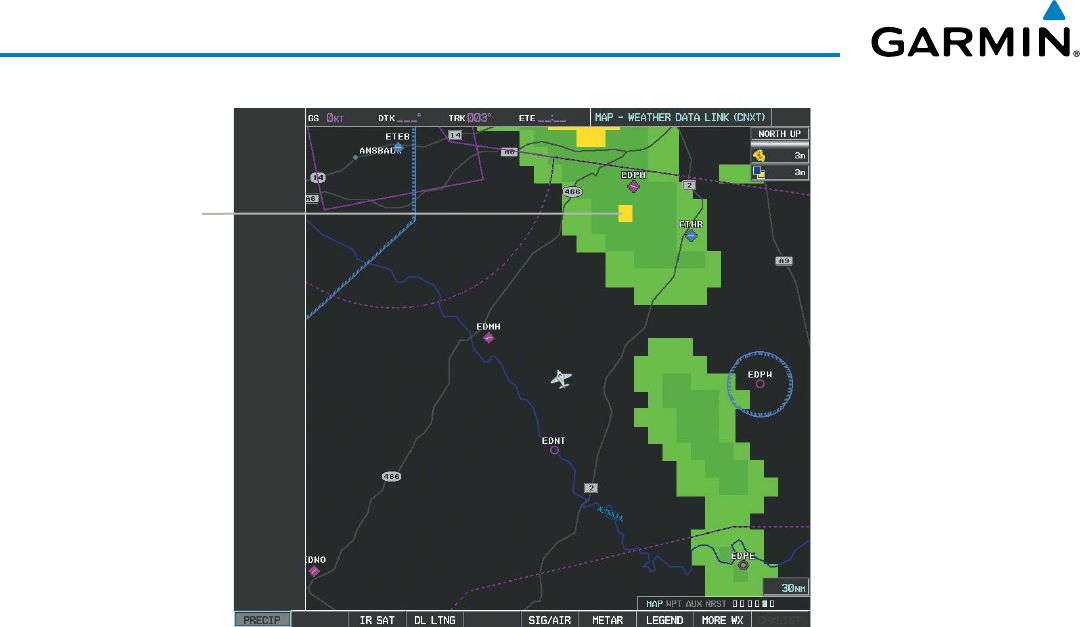
Garmin G1000 Pilot’s Guide for the Beechcraft 200/B200 Series
190-00928-04 Rev. A362
HAZARD AVOIDANCE
Figure 6-67 Precipitation Data - Zoomed
Block represents
4 km
2
The following may cause abnormalities in displayed radar images:
• Ground clutter
• Strobes and spurious radar data
• Sun strobes (when the radar antenna points directly at the sun)
• Interference from buildings or mountains, which may cause shadows
• Metallic dust from military aircraft, which can cause alterations in radar scans
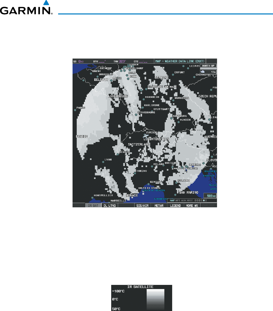
190-00928-04 Rev. A
Garmin G1000 Pilot’s Guide for the Beechcraft 200/B200 Series
363
HAZARD AVOIDANCE
INFRARED SATELLITE
Infrared Satellite (IR SAT) data (Figure 6-68) depicts cloud top temperatures from satellite imagery. Brighter
cloud top colors indicate cooler temperatures occurring at higher altitudes.
Figure 6-68 Infrared Satellite Data on the Weather Data Link (CNXT) Page
Displaying Cloud Tops information:
1) Select the Weather Data Link (CNXT) Page.
2) Select the IR SAT Softkey.
To display the Infrared Satellite legend (Figure 6-69), select the
LEGEND
Softkey when Infrared Satellite data
is selected for display.
Figure 6-69 Infrared Satellite Legend
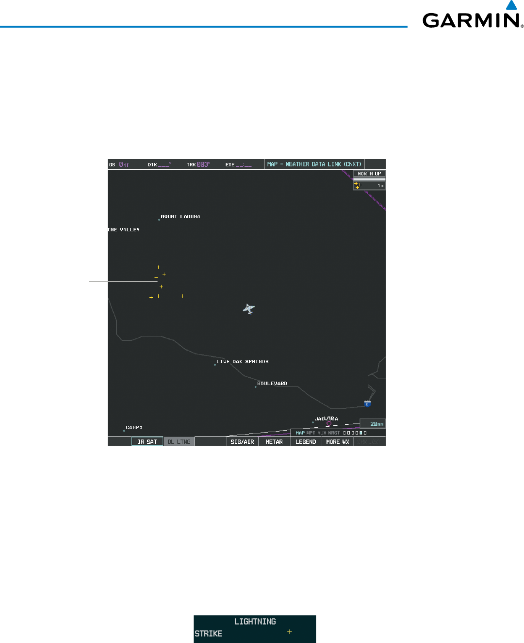
Garmin G1000 Pilot’s Guide for the Beechcraft 200/B200 Series
190-00928-04 Rev. A364
HAZARD AVOIDANCE
DATA LINK LIGHTNING
The Data Link Lightning (DL LTNG) weather product (Figure 6-70) shows the approximate location of
cloud-to-ground lightning strikes. A strike icon represents a strike that has occurred within a two-kilometer
region. Neither cloud-to-cloud nor the exact location of the lightning strike is displayed.
If the aircraft is also equipped with the optional on-board lightning detection system, only one lightning
source may be enabled on a Navigation Map at a time.
Figure 6-70 Data Link Lightning Weather Product on the Weather
Data Link (CNXT) Page
Lightning Strikes
Displaying Data Link Lightning information:
1) Select the MAP Softkey (for the PFD Inset Map, select the INSET Softkey). This step is not necessary on the
Weather Data Link (CNXT) Page.
2) Select the DL LTNG Softkey.
To display the Datalink Lightning legend on the Weather Data Link (CNXT) Page (Figure 6-71), select the
LEGEND
Softkey when Datal Link Lightning is selected for display.
Figure 6-71 Datal Link Lightning Legend
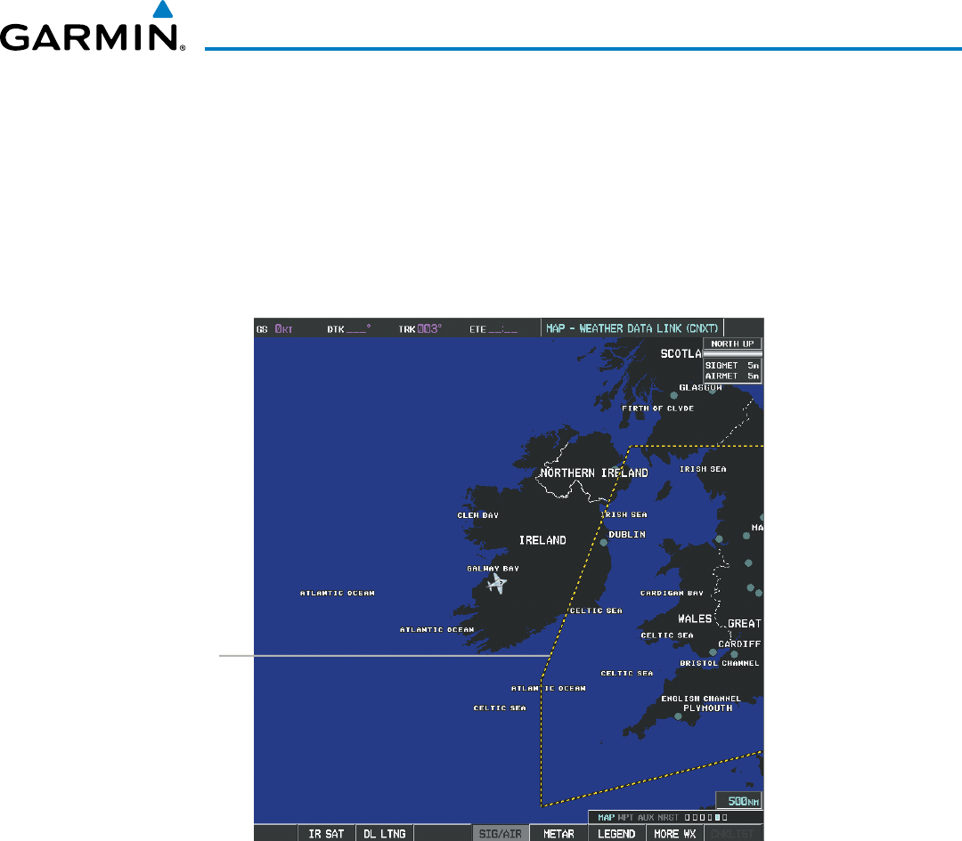
190-00928-04 Rev. A
Garmin G1000 Pilot’s Guide for the Beechcraft 200/B200 Series
365
HAZARD AVOIDANCE
SIGMETS AND AIRMETS
SIGMETs (SIGnificant METeorological Information) and AIRMETs (AIRmen’s METeorological Information)
are issued for potentially hazardous weather. A Convective SIGMET is issued for hazardous convective
weather such as severe or widespread thunderstorms. A localized SIGMET can be displayed when significant
weather conditions are not widespread.
The entire SIGMET or AIRMET is displayed as long as any portion of it is issued within the coverage area
of the Connext Data Request.
Figure 6-72 SIGMET/AIRMET Data
SIGMET
Displaying SIGMETs and AIRMETs:
1) Select the Weather Data Link (CNXT) Page.
2) Select the SIG/AIR Softkey.
3) To view the text of the
SIGMET or AIRMET, press the
RANGE Knob
and move the Map Pointer over the
icon.
4)
Press the ENT key. Figure 6-73 shows sample SIGMET text.
To display the SIGMET and AIRMET legend (Figure 6-74), select the
LEGEND
Softkey when SIGMETs and
AIRMETs are selected for display.
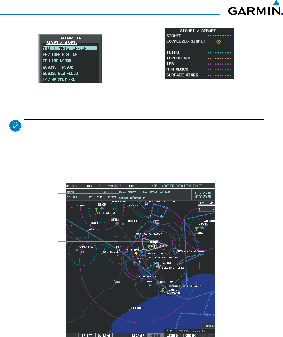
Garmin G1000 Pilot’s Guide for the Beechcraft 200/B200 Series
190-00928-04 Rev. A366
HAZARD AVOIDANCE
Figure 6-74 SIGMET/AIRMET Legend
Figure 6-73 Sample SIGMET Text
METARS AND TAFS
NOTE: METAR information is only displayed within the installed aviation database service area.
METARs (METeorological Aerodrome Reports) typically contain information about the temperature,
dewpoint, wind, precipitation, cloud cover, cloud base heights, visibility, and barometric pressure at an
airport or observation station. They can also contain information on precipitation amounts, lightning, and
other critical data. METARs reflect hourly observations; non-routine updates include the code “SPECI” in the
report. METARs are shown as colored flags at airports that provide them.
Figure 6-75 METAR Flags on the Weather Data Link (CNXT) Page
Instructions
for Viewing
METAR and
TAF Text
Selected
Airport
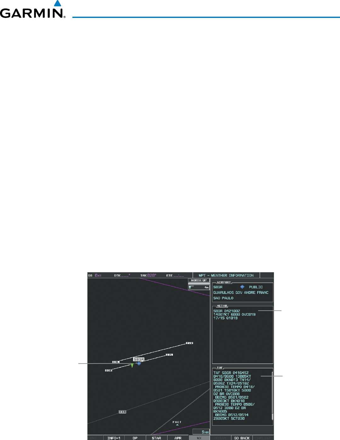
190-00928-04 Rev. A
Garmin G1000 Pilot’s Guide for the Beechcraft 200/B200 Series
367
HAZARD AVOIDANCE
TAFs (Terminal Aerodrome Forecasts) are weather predictions for specific airports within a 24- hour period,
and may span up to 36 hours. TAFs typically include forecast wind, visibility, weather phenomena, and sky
conditions using METAR codes.
METAR and TAF text are displayed on the Weather Information Page. TAF information is displayed in its
raw form when it is available.
Displaying METAR and TAF text:
1) On the Weather Data Link (CNXT) Page, select the METAR Softkey.
2) Press the RANGE Knob and pan to the desired airport.
3) Press the ENT Key. The Weather Information Page is shown with METAR and TAF text.
4) Use the FMS Knob or the ENT Key to scroll through the METAR and TAF text. METAR text must be completely
scrolled through before scrolling through the TAF text.
5) Press the FMS Knob or the CLR Key to return to the Weather Data Link (CNXT) Page.
Or:
1) Select the Weather Information Page.
a) Turn the large
FMS
Knob to select the Waypoint Page Group.
b) Select the WX Softkey to select the Weather Information Page.
2) Press the FMS Knob to display the cursor.
3) Use the FMS Knob to enter the desired airport and press the
ENT
Key.
4) Use the FMS Knob or the ENT Key to scroll through the METAR and TAF text. Note that the METAR text must
be completely scrolled through before scrolling through the TAF text.
TAF
Text
METAR
Symbol
Figure 6-76 METAR and TAF Text
METAR
Text
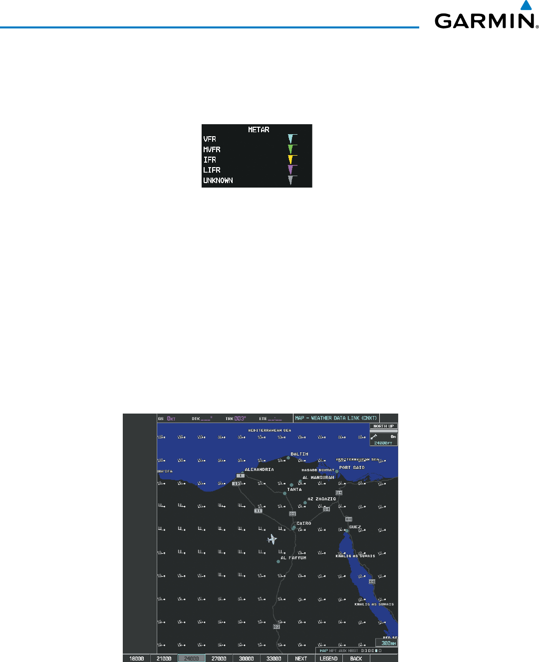
Garmin G1000 Pilot’s Guide for the Beechcraft 200/B200 Series
190-00928-04 Rev. A368
HAZARD AVOIDANCE
To display the METAR legend on the Weather Data Link (CNXT) Page (Figure 6-77), select the
LEGEND
Softkey when METARs are selected for display.
The METAR flag color is determined by the information in the METAR text. A gray METAR flag is displayed
when the METAR text does not contain adequate information.
Figure 6-77 METAR Legend
WINDS ALOFT
Winds Aloft data (Figure 6-78) shows the forecasted wind speed and direction at the surface and at selected
altitudes. Altitude can be displayed in 3,000-foot increments from the surface up to 42,000 feet MSL.
Displaying Winds Aloft data:
1) Select the Weather Data Link (CNXT) Page.
2) Select the
MORE WX
Softkey.
3) Select the
WIND
Softkey.
4) Select the desired altitude level: SFC (surface) up to 42,000 feet. Select the
NEXT
or
PREV
Softkey to cycle
through the altitude softkeys. The
WIND
Softkey label changes to reflect the altitude selected.
Figure 6-78 Winds Aloft at 24,000 Feet
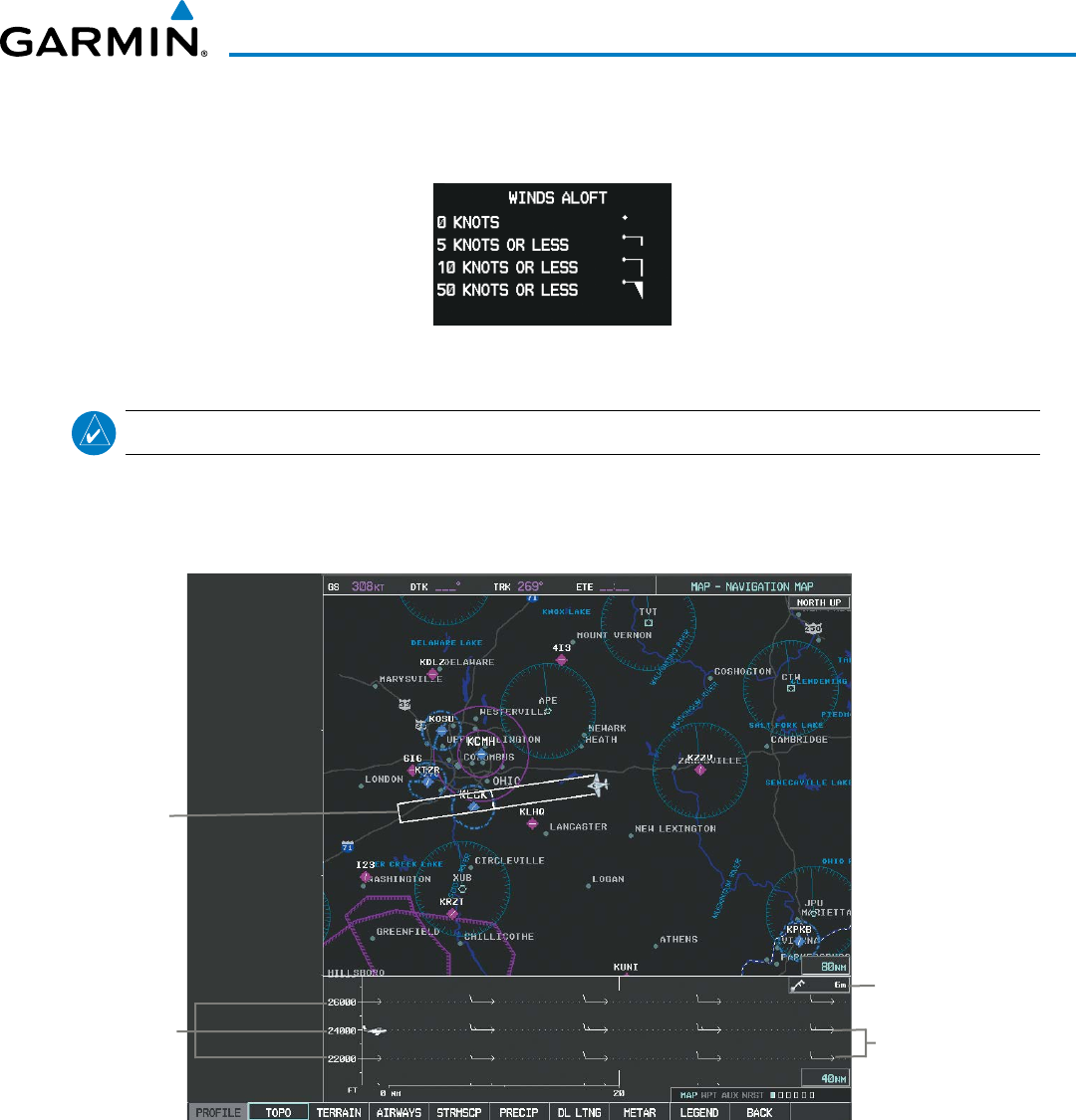
190-00928-04 Rev. A
Garmin G1000 Pilot’s Guide for the Beechcraft 200/B200 Series
369
HAZARD AVOIDANCE
To display the Winds Aloft legend (Figure 6-79), select the
LEGEND
Softkey when Winds Aloft is
selected for display.
Figure 6-79 Winds Aloft Data with Legend
NOTE: Profile View is not available if the TAWS-A option is installed.
Headwind and tailwind components aloft are available inside the Profile View on the Navigation Map Page
(Figure 6-80). The displayed components are relative to current aircraft altitude and track, but not to aircraft
speed.
Figure 6-80 Navigation Map Page with Winds Aloft Data on Profile View
Wind Component
Velocity and Direction
Arrows
Winds Aloft Data Age
Altitude Scale
Profile View
Path Enabled
Arrows pointing to the left indicate headwind components; tailwind component arrows point to the right,
as shown in Table 6-7.
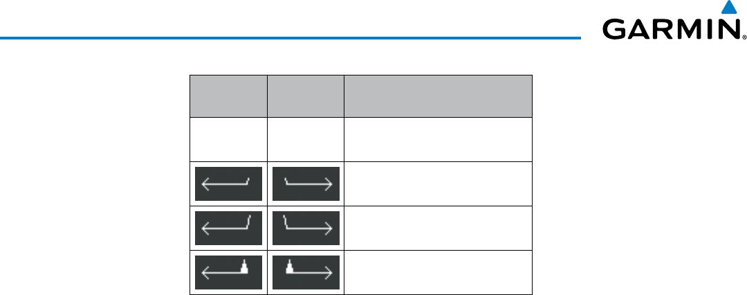
Garmin G1000 Pilot’s Guide for the Beechcraft 200/B200 Series
190-00928-04 Rev. A370
HAZARD AVOIDANCE
Headwind
Symbol
Tailwind
Symbol
Headwind/Tailwind
Component
None None Less than 5 knots
5 knots
10 knots
50 knots
Table 6-7 Profile View Headwind/Tailwind Component Symbols
Showing/Hiding Profile View (containing winds aloft data)
1) Select the Navigation Map Page.
2) Select the PROFILE Softkey.
Or:
1) Press the MENU Key.
2) Turn the large FMS Knob to highlight ‘Show Profile View’ or ‘Hide Profile View’ (choice dependent on current
state) and press the
ENT
Key.
Winds Aloft data inside the Profile View is enabled by default when the Profile View is displayed on the
Navigation Map Page. This behavior can be changed on the Navigation Map Page.
Enabling/disabling winds aloft data display in Profile View:
1) Select the Navigation Map Page.
2) Press the MENU Key.
3) With Map Setup highlighted, press the
ENT
Key (Figure 6-81).
4) Turn the small FMS Knob to select the Profile Group and press the ENT Key (Figure 6-82).
5) Turn the large
FMS
Knob to select ‘Profile Winds’ (Figure 6-83).
6) Turn the small
FMS
Knob to select ‘On’ or ‘Off’.
7) Press the FMS Knob or CLR Key to return to the Navigation Map Page with the changed settings.
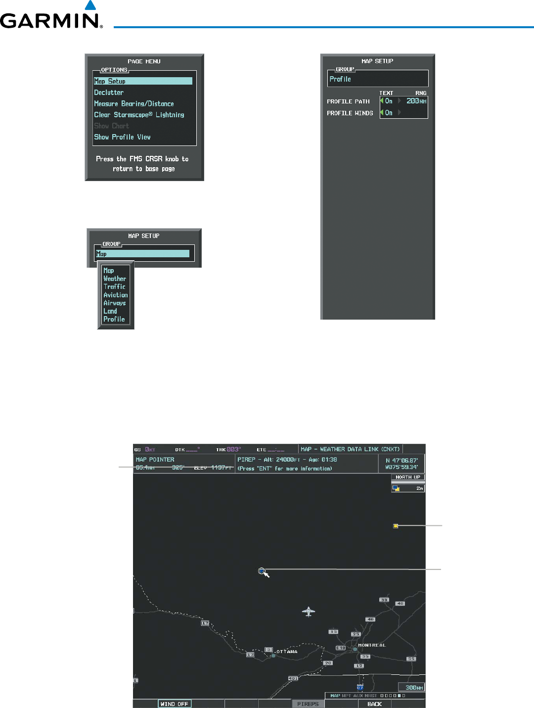
190-00928-04 Rev. A
Garmin G1000 Pilot’s Guide for the Beechcraft 200/B200 Series
371
HAZARD AVOIDANCE
Figure 6-82 Navigation Map Page Setup Menu
Figure 6-81 Navigation Map Page Menu
Figure 6-83 Navigation Map Page Setup Menu, Weather Group
PIREPS
Pilot Weather Reports (PIREPs) describe in-flight weather encountered by pilots. A PIREP may contain
adverse weather conditions, such as low in-flight visibility, icing conditions, wind shear, turbulence, and type
of aircraft flown. PIREPs are issued as either Routine (UA) or Urgent (UUA).
Figure 6-84 PIREPs on the Weather Data Link (CNXT) Page
Instructions for
Viewing PIREP
Text
PIREP
Selected
Urgent
PIREP
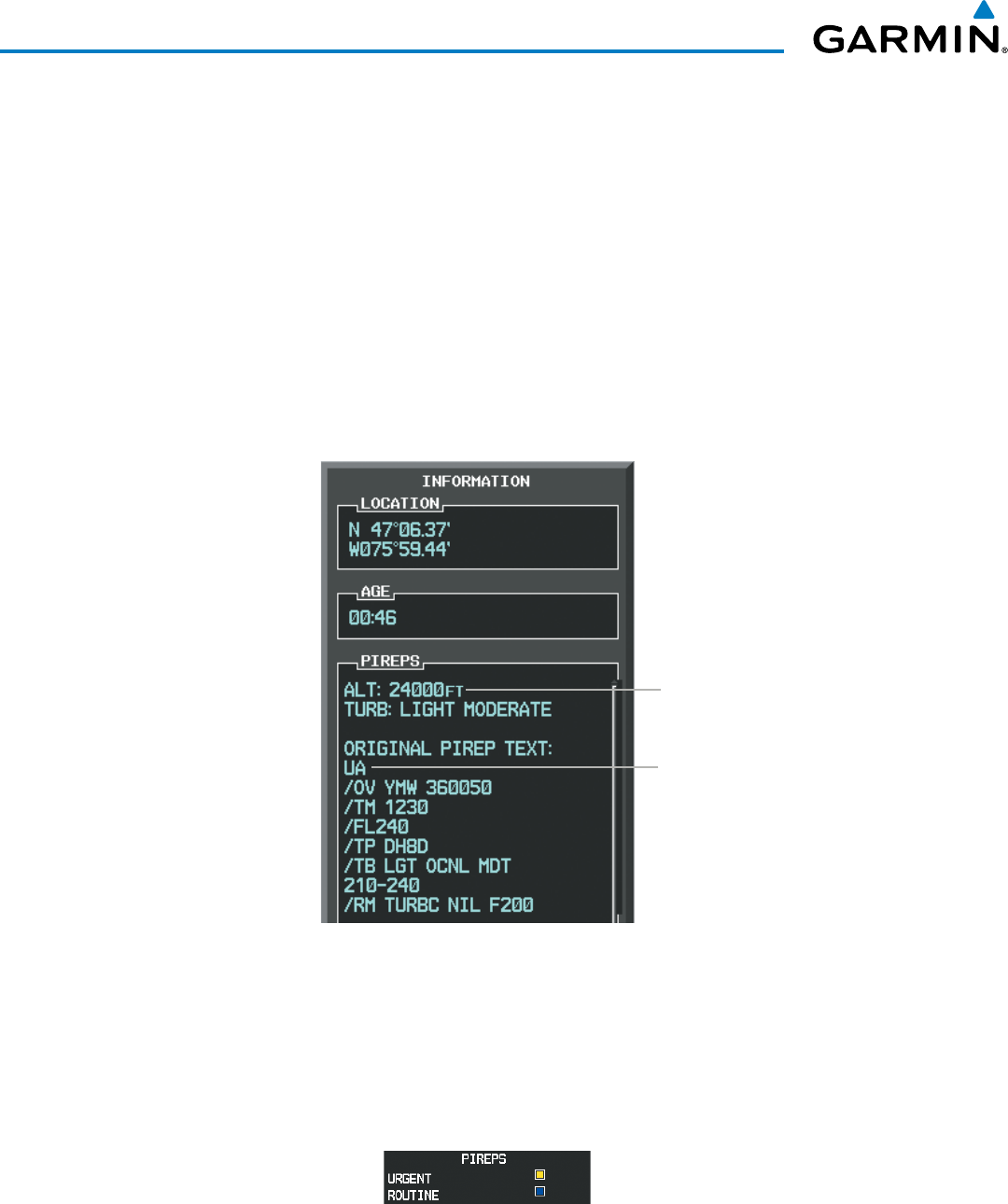
Garmin G1000 Pilot’s Guide for the Beechcraft 200/B200 Series
190-00928-04 Rev. A372
HAZARD AVOIDANCE
Displaying PIREP text:
1) Select the Weather Data Link (CNXT) Page.
2) Select the
MORE WX
Softkey.
3) Select the
PIREPS
Softkey.
4) Press the RANGE Knob and pan to the desired weather report. A gray circle will appear around the weather
report when it is selected.
5) Press the ENT Key. The PIREP tex is first displayed in a decoded fashion, then as raw text.
6) Use the FMS Knob or the ENT Key to scroll through the PIREP text.
7) Press the FMS Knob or the CLR Key to close the PIREP text window and return to the Weather Data Link (CNXT)
Page.
Figure 6-85 PIREP Text on the Weather Data
Link (CNXT) Page
Decoded PIREP Text
Original PIREP Text
To display the PIREP or AIREP legend (Figure 6-86), select the
LEGEND
Softkey when PIREPs or AIREPs
are selected for display.
The PIREP color is determined by the type (routine or urgent).
Figure 6-86 AIREPs & PIREPs Legend
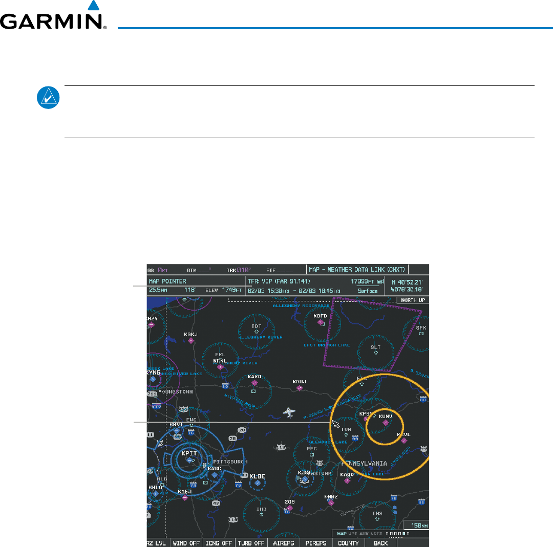
190-00928-04 Rev. A
Garmin G1000 Pilot’s Guide for the Beechcraft 200/B200 Series
373
HAZARD AVOIDANCE
TFRS
NOTE: Temporary Flight Restriction (TFR) data from Garmin Connext is only available in the United States
(not including any U.S. territories.) Refer to fly.garmin.com/fly-garmin/gfds-weather for product coverage
information.
In the United States, the FAA issues Temporary Flight Restrictions (TFRs) to designate areas where
flight is restricted. TFRs are issued to restrict flight for a variety of reasons including national security, law
enforcement, natural disasters., airshows, and large sporting events. TFRs may be issued at any time, and
TFR data displayed on the G1000 is only intended to supplement official TFR information obtained from
Flight Service Stations (FSS), and air traffic control.
The age of TFR data is not shown; however, if TFR data is not available or has expired, the system displays
‘TFR N/A’ in the upper-left corner of maps on which TFRs can be displayed.
Figure 6-87 TFR Data on the Weather Data Link (CNXT) Page
TFR Summary
Data
TFR
Selected
with Map
Pointer
Displaying TFR Data:
1) Select the Weather Data Link (CNXT) Page or Navigation Map Page.
2) Press the RANGE Knob and pan the map pointer over a TFR to highlight it. The system displays TFR summary
information above the map.
3) Press the ENT Key. The system displays a pop-up menu.
4) If necessary, turn the FMS Knob to select ‘Review Airspaces’ and press the ENT Key. The system displays the
TFR Information window.
5) Press the FMS Knob or the CLR Key to remove the TFR Information window.
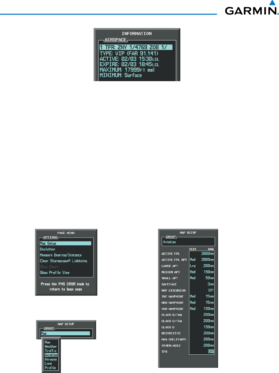
Garmin G1000 Pilot’s Guide for the Beechcraft 200/B200 Series
190-00928-04 Rev. A374
HAZARD AVOIDANCE
Figure 6-88 Full Text for Selected TFR
The setup menus for the Navigation Map Page control the map range settings above which TFR data is
decluttered from the display. If a map range larger than the TFR product map range setting is selected, the TFR
product data is removed from the map.
Maps other than the Navigation Map Page use settings based on those selected for the Navigation Map Page.
Setting up and customizing TFR data for maps on which TFR data can be displayed:
1) Select the Navigation Map Page.
2) Press the MENU Key.
3) With Map Setup highlighted, press the
ENT
Key (Figure 6-89).
4) Turn the small FMS Knob to select the Aviation Group and press the ENT Key (Figure 6-90).
5) Turn the large
FMS
Knob to scroll to the TFR product range setting (Figure 6-91).
6) Turn the small
FMS
Knob to scroll through options (Off, range settings).
7) Press the
ENT
Key to select an option.
8) Press the FMS Knob or CLR Key to return to the Navigation Map Page with the changed settings.
Figure 6-90 Navigation Map Page Setup Menu
Figure 6-89 Navigation Map Page Menu
Figure 6-91 Navigation Map Page Setup Menu, Weather Group

190-00928-04 Rev. A
Garmin G1000 Pilot’s Guide for the Beechcraft 200/B200 Series
375
HAZARD AVOIDANCE
ABNORMAL OPERATIONS
If the G1000 cannot complete a Connext Data Request, one or more messages will appear in the REQUEST
STATUS Window.
Weather Request
Status Message
Description
Auto requests inhibited
Send manual request to
reset.
The system has disabled automatic weather data requests due to excessive errors. Automatic
weather data requests have stopped. Send a manual weather data request to resume automatic
updates.
Auto update retry: ##
Seconds
The system will attempt another automatic weather data request after an error occurred during the
previous request. Timer counts down until the next automatic request occurs.
Connext Comm Error [2] A communications error has occurred with the GDL59 or GIA. The G1000 should be serviced.
Connext Comm Error [4] This occurs if multiple automatic weather data requests have recently failed, or the GDL 59 or a GIA
is off-line.
Connext Comm Error [5] This can occur if the GDL 59 is off-line or not configured, or the Iridium or Garmin Connext services
are not accessible. Check Iridium signal strength. If this error persists, the G1000 should be
serviced.
Connext Comm Error [6] A communications error has occurred. It this error persists, the G1000 should be serviced.
Connext Comm Error [7] A weather data transfer has timed out. Check Iridium signal strength and re-send the data request.
Connext Comm Error [8] A server error has occurred or invalid data received.
Connext Login Invalid There is a problem with the Garmin Connext registration. Contact Garmin at 1-866-739-5687 in
the United States or 913-397-8200, ext. 1135 for assistance.
Connext Server
Temporarily Inop
The Garmin Connext Weather data server is temporarily out of service, but is expected to return to
service in less than 30 minutes.
Connext Server Inop The Garmin Connext Weather data server will be out of service for at least 30 minutes.
Invalid Coverage Area The weather data request coverage area does not contain at least one of the following: a
waypoint, a flight plan, or a flight plan destination. Verify at least one of the coverage options is
enabled (checked) and contains required criteria, then re-send the data request.
No Connext
Subscription
The system is not be currently subscribed to Garmin Connext services or the access code is
incorrect. Verify the access code. Contact Garmin at 1-866-739-5687 in the United States or 913-
397-8200, ext. 1135 for assistance.
Reduce Request Area The size of the received weather data has exceeded system memory limits. Reduce the size of the
coverage area and issue another Connext Data Request to ensure all available weather data has
been received.
Request Cancelled The user has cancelled a Connext Data Request.
Requested area too
large. Reduce coverage
area.
The Garmin Connext Weather service has determined the size of the requested weather data exceeds
system memory limits.
Reduce the size of the coverage area and issue another Connext Data
Request to ensure all available weather data has been received.
Request Failed - Try
Again
The weather data request timed-out. Re-send data request.
Transfer Preempted
The GDL 59 is busy. Retry request later.
Table 6-8 Abnormal Garmin Connext Weather Request Status Messages

Garmin G1000 Pilot’s Guide for the Beechcraft 200/B200 Series
190-00928-04 Rev. A376
HAZARD AVOIDANCE
GARMIN CONNEXT WEATHER IN REVERSIONARY MODE
When the G1000 is operating in Reversionary Mode, only those weather products which can be displayed
on the PFD Inset map will be available for display (see Table 6-5 for a list of weather products and their
associated map availability).
If manual Connext Data Requests were enabled prior to entering Reversionary Mode, no new weather data
will be retrieved while operating in Reversionary Mode. If automatic Connext Data Requests were enabled
prior to Reversionary Mode operation, the system will continue the automatic data requests in Reversionary
Mode (provided automatic requests have not been inhibited due to a system error).

190-00928-04 Rev. A
Garmin G1000 Pilot’s Guide for the Beechcraft 200/B200 Series
377
HAZARD AVOIDANCE
6.3 AIRBORNE COLOR WEATHER RADAR
SYSTEM DESCRIPTION
The Garmin GWX 68 Airborne Color Weather Radar is a four-color digital pulsed radar with 6.5 kilowatts
of output power. It combines excellent range and adjustable scanning profiles with a high-definition target
display. The pulse width is four microseconds (µs) on all ranges except the 2.5 nm range. The GWX 68 uses a
one µs pulse width at this range to reduce the targets smearing together on the display for better target definition
at close range.
The Garmin GWX 70 Airborne Color Weather Radar is a solid-state pulsed radar with forty watts of output
power. The radar combines excellent range and adjustable scanning profiles with a high-definition target
display. The GWX 70 has an effective pulse length of 27.31 microseconds (µs), and the system optimizes the
pulse length to maximize resolution at each range setting.
The KingAir 200/B200 Series uses a 12-inch phased array antenna that is fully stabilized to accommodate 30º
of pitch and roll.
To focus radar scanning on specific areas, Sector Scanning offers pilot-adjustable horizontal scan angles. A
vertical scanning function helps to analyze storm tops, gradients, and cell buildup activity at various altitudes.
Radar features include:
• Extended Sensitivity Time Constant (STC) logic that automatically correlates distance of the return echo with
intensity, so cells do not suddenly appear to get larger as they get closer.
• WATCH™ (Weather ATtenuated Color Highlight) helps identify possible shadowing effects of short-range
cell activity, identifying areas where radar return signals are weakened or attenuated by intense precipitation
(or large areas of lesser precipitation) and may not fully reflect the weather behind a storm.
• Weather Alert that looks ahead for intense cell activity in the 80-320 nm range, even if these ranges are not
being monitored.
PRINCIPLES OF PULSED AIRBORNE WEATHER RADAR
The term RADAR is an acronym for RAdio Detecting And Ranging. Pulsed radar locates targets by transmitting
a microwave pulse beam that, upon encountering a target, is reflected back to the radar receiver as a return
echo. The microwave pulses are focused and radiated by the antenna, with the most intense energy in the
center of the beam and decreasing intensity near the edge. The same antenna is used for both transmitting and
receiving. The G1000 processes the returned signal and displays it on the MFD.
Radar detection is a two-way process that requires 12.36 µs for the transmitted microwave pulses to travel out
and back for each nautical mile of target range. It takes 123.6 µs for a transmitted pulse to make the round trip
if a target is ten nautical miles away.
Airborne weather radar should be used to avoid severe weather, not for penetrating severe weather. The
decision to fly into an area of radar targets depends on target intensity, spacing between the targets, aircraft
capabilities, and pilot experience. Pulse type weather radar detects only precipitation, not clouds or turbulence.
The display may indicate clear areas between intense returns, but this does not necessarily mean it is safe to fly
between them.
Airborne weather radar has other capabilities beyond weather detection. It also has the ability to detect and
provide distance to cities, mountains, coastlines, rivers, lakes, and oceans.
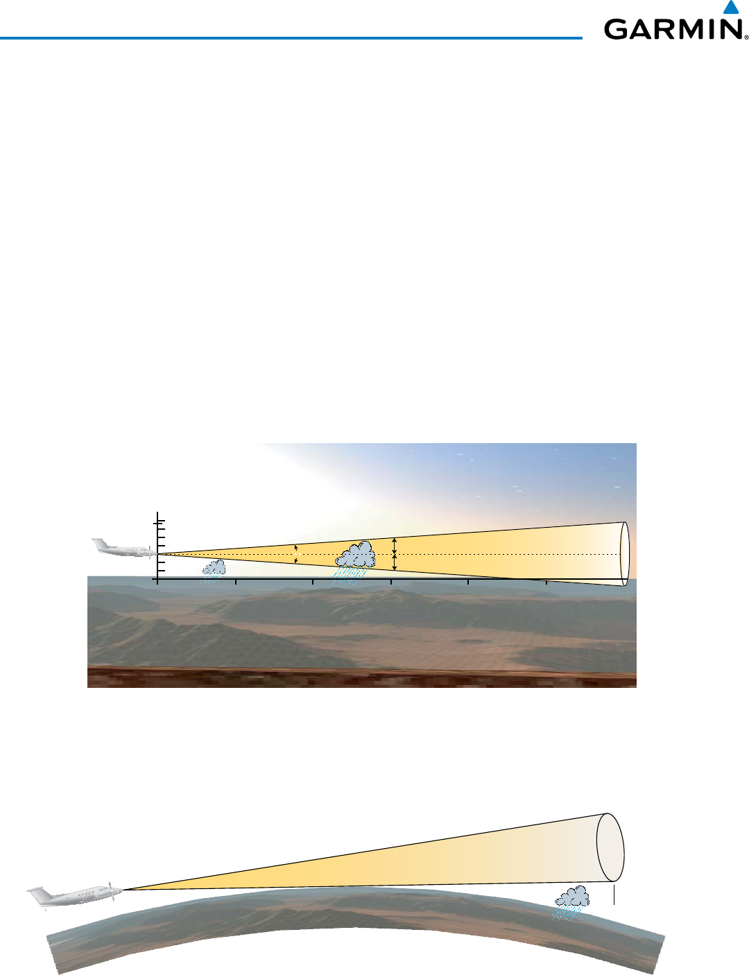
Garmin G1000 Pilot’s Guide for the Beechcraft 200/B200 Series
190-00928-04 Rev. A378
HAZARD AVOIDANCE
NEXRAD AND AIRBORNE WEATHER RADAR
Both Airborne Weather Radar and NEXRAD measure weather reflectivity in decibels (dB). A decibel is a
logarithmic expression of the ratio of two quantities. Airborne Weather Radar measures the ratio of power
against the gain of the antenna, while NEXRAD measures the energy reflected back to the radar, or the radar
reflectivity ratio.
Both systems use colors to identify the different echo intensities, but the colors are not interchangeable.
Airborne color radar values used by Garmin Airborne Color Weather Radar should not be confused with
NEXRAD radar values.
ANTENNA BEAM ILLUMINATION
The radar beam is much like the beam of a spotlight. The further the beam travels, the wider it becomes.
The radar is only capable of seeing what is inside the boundaries of the beam. The figure below depicts a radar
beam’s characteristics. The figure illustrates vertical dimensions of the radar beam, although the same holds
true for the horizontal dimensions. In other words, the beam is as wide as it is tall. Note that it is possible to
miss areas of precipitation on the radar display because of the antenna tilt setting. With the antenna tilt set
to zero in this illustration, the beam overshoots the precipitation at 15 nautical miles.
Figure 6-92 Radar Beam from a 12 inch Antenna
0
80
Altitude (x1000 ft.)
30 0 45 60 75 90
Range (nautical miles)
Half Power at Beam Sidelobes
Antenna at Zero Tilt
18,000 ft.
18,000 ft.
Max Power at Beam Center
15
8°
The curvature of the earth can also be a factor in missing areas of precipitation, especially at range settings
of 150 nautical miles or more. Here the beam overshoots the precipitation at less than 320 nautical miles.
320 nm
Figure 6-93 Radar Beam in Relation to the Curvature of the Earth

190-00928-04 Rev. A
Garmin G1000 Pilot’s Guide for the Beechcraft 200/B200 Series
379
HAZARD AVOIDANCE
RADAR SIGNAL ATTENUATION
The phenomenon of radar signal attenuation affects the operation of weather radar. When the radar signal
is transmitted, it is progressively absorbed and scattered, making the signal weaker. This weakening, or
attenuation, is caused by two primary sources, distance and precipitation.
Attenuation because of distance is due to the fact that the radar energy leaving the antenna is inversely
proportional to the square of the distance. The reflected radar energy from a target 40 miles away that fills
the radar beam is one fourth the energy reflected from an equivalent target 20 miles away. This would appear
to the operator that the storm is gaining intensity as the aircraft gets closer. Internal signal processing within
the radar system compensates for much of this distance attenuation.
Attenuation due to precipitation is not as predictable as distance attenuation. It is also more intense. As the
radar signal passes through moisture, a portion of the radar energy is reflected back to the antenna. However,
much of the energy is absorbed. If precipitation is very heavy, or covers a large area, the signal may not
reach completely through the area of precipitation. The weather radar system cannot distinguish between an
attenuated signal and an area of no precipitation. If the signal has been fully attenuated, the radar displays
a radar shadow. This appears as an end to the precipitation when, in fact, the heavy rain may extend much
further. A cell containing heavy precipitation may block another cell located behind the first, preventing it
from being displayed on the radar. Never fly into these shadowed areas and never assume that all of the heavy
precipitation is being displayed unless another cell or a ground target can be seen beyond the heavy cell. The
WATCH™ feature can help in identifying these shadowed areas. Areas in question appear as shadowed or
gray on the radar display. Proper use of the antenna tilt control can also help detect radar shadows.
Attenuation can also be due to poor maintenance or degradation of the radome. Even the smallest amount of
wear and scratching, pitting, and pinholes on the radome surface can cause damage and system inefficiency.
RADAR SIGNAL REFLECTIVITY
PReciPitation
Precipitation or objects more dense than water, such as the surface of the earth or solid structures, are
detected by the weather radar. The weather radar does not detect clouds, thunderstorms, or turbulence
directly. It detects precipitation associated with clouds, thunderstorms, and turbulence. The best radar
signal reflectors are raindrops, wet snow, or wet hail. The larger the raindrop, the better the reflectivity. The
size of the precipitation droplet is the most important factor in radar reflectivity. Because large drops in a
small concentrated area are characteristic of a severe thunderstorm, the radar displays the storm as a strong
return. Ice crystals, dry snow, and dry hail have low levels of reflectivity as shown in the illustration, and
often not displayed by the radar. Additionally, a cloud that contains only small raindrops, such as fog or
drizzle, does not reflect enough radar energy to produce a measurable target return.
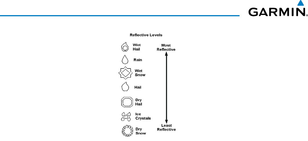
Garmin G1000 Pilot’s Guide for the Beechcraft 200/B200 Series
190-00928-04 Rev. A380
HAZARD AVOIDANCE
Figure 6-94 Precipitation Type and Reflectivity
gRounD RetuRnS
The intensity of ground target returns depends upon the angle at which the radar beam strikes the
ground target (Angle of Incidence) and the reflective properties of that target. The gain can be adjusted so
shorelines, rivers, lakes, and cities are well-defined. Increasing the gain too much causes the display to fill
in between targets, thus obscuring some landmarks.
Cities normally provide a strong return signal. While large buildings and structures provide good returns,
small buildings can be shadowed from the radar beam by the taller buildings. As the aircraft approaches
and shorter ranges are selected, details become more noticeable as the highly reflective regular lines and
edges of the city become more defined.
Bodies of water such as lakes, rivers, and oceans are not good reflectors and normally do not provide good
returns. The energy is reflected in a forward scatter angle with inadequate energy being returned. They
can appear as dark areas on the display. However, rough or choppy water is a better reflector and provides
stronger returns from the downwind sides of the waves.
Mountains also provide strong return signals to the antenna, but also block the areas behind. However,
over mountainous terrain, the radar beam can be reflected back and forth in the mountain passes or off
canyon walls, using up all or most of the radar energy. In this case, no return signal is received from this
area, causing the display to show a dark spot which could indicate a pass where no pass exists.
angle oF inciDence
The angle at which the radar beam strikes the target is called the Angle of Incidence. The figure illustrates
the incident angle (‘A’). This directly affects the detectable range, the area of illumination, and the intensity
of the displayed target returns. A large incident angle gives the radar system a smaller detectable range and
lower display intensity due to minimized reflection of the radar energy.
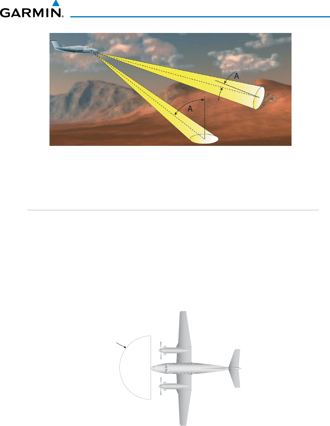
190-00928-04 Rev. A
Garmin G1000 Pilot’s Guide for the Beechcraft 200/B200 Series
381
HAZARD AVOIDANCE
Figure 6-95 Angle of Incidence
A smaller incident angle gives the radar a larger detectable range of operation and the target display shows
a higher intensity. Since more radar energy is reflected back to the antenna with a low incident angle, the
resulting detectable range is increased for mountainous terrain.
SAFE OPERATING DISTANCE
The following information establishes a minimum safe distance from the antenna for personnel near
operating weather radar. The minimum safe distance is based on the FCC’s exposure limit at 9.3 to 9.5 GHz for
general population/uncontrolled environments, which is 1 mW/cm2. See Advisory Circular 20-68B for more
information on safe distance determination.
MAXIMUM PERMISSIBLE EXPOSURE LEVEL (MPEL)
The zone in which the radiation level exceeds the US Government standard of 1 mW/cm2 is the semicircular
area of at least 11 feet from the 12-inch antenna. All personnel must remain outside of this zone. With a
scanning or rotating beam, the averaged power density at the MPEL boundary is significantly reduced.
11’ for 12”
antenna
MPEL
Boundary
Figure 6-96 MPEL Boundary
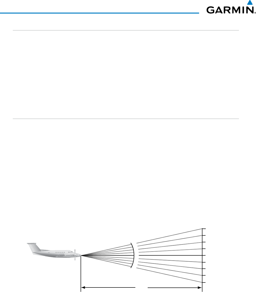
Garmin G1000 Pilot’s Guide for the Beechcraft 200/B200 Series
190-00928-04 Rev. A382
HAZARD AVOIDANCE
BASIC ANTENNA TILT SETUP
The following discussion is a simple method for setting up the weather radar antenna tilt for most situations.
It is not to be considered an all encompassing setup that works in all situations, but this method does provide
good overall parameters for the monitoring of threats. Ultimately, it is desired to have the antenna tilted so that
the bottom of the radar beam is four degrees below parallel with the ground. The following example explains
one way of achieving this.
With the aircraft flying level, adjust the antenna tilt so ground returns are displayed at a distance that equals
the aircraft’s current altitude (AGL) divided by 1,000. For example, if the aircraft is at 14,000 feet, adjust the
tilt so the front edge of ground returns are displayed at 14 nautical miles. Note this antenna tilt angle setting.
Now, raise the antenna tilt 6 degrees above this setting. The bottom of the radar beam is now angled down 4º
from parallel with the ground.
PRACTICAL APPLICATION USING THE BASIC TILT SETUP
With the antenna tilt set as previously described, any displayed target return should be scrutinized when
flying at altitudes between 2,000 and 30,000 feet AGL. If the displayed target advances on the screen to within
5 nautical miles of the aircraft, avoid it. This may be either weather or ground returns that are 2,000 feet or less
below the aircraft. Raising the antenna tilt 4 degrees can help separate ground returns from weather returns in
relatively flat terrain. This aligns the bottom of the radar beam parallel with the ground. Return the antenna
tilt to the previous setting after a few sweeps.
If the aircraft is above 29,000 feet, be cautious of any target return that gets to within 30 nautical miles. This is
likely a thunderstorm that has a top high enough that the aircraft cannot fly over it safely.
If the aircraft altitude is 15,000 feet or lower, setting the displayed range to 60 miles may be more helpful.
Closely monitor anything that enters the display.
Also, after setting up the antenna tilt angle as described previously, ground returns can be monitored for possible
threats. The relationship between antenna tilt angle, altitude, and distance is one degree of tilt equals 100 feet of
altitude for every one nautical mile.
Vertical Change of Radar Beam (feet)
Change in Antenna Tilt
10 nm
0
1000
2000
3000
4000
1000
2000
3000
4000
-1°
0°
-2°
-3°
-4°
+1°
+2°
+3°
+4°
Figure 6-97 Vertical Change in Radar Beam per Nautical Mile
Therefore, with the antenna tilt set so that the bottom of the beam is four degrees below parallel with
the ground, a target return at 10 nm is approximately 4,000 feet below the aircraft; at 20 nm, 8,000 feet;
at 50 nm, 20,000 feet. In other words, at this tilt setting, a ground return (such as a mountain peak) being
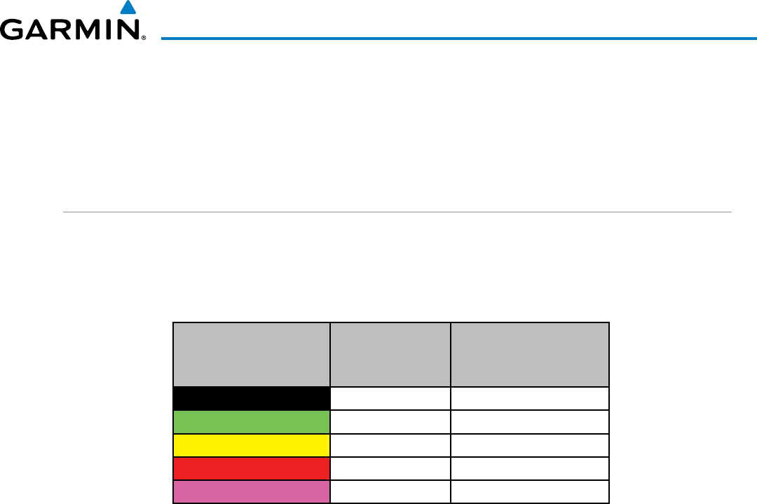
190-00928-04 Rev. A
Garmin G1000 Pilot’s Guide for the Beechcraft 200/B200 Series
383
HAZARD AVOIDANCE
displayed at 10 nm would have a maximum distance below the aircraft of 4,000 feet. When the ground target
return moves to 5 nm, maximum distance below the aircraft is 2,000 feet.
This setup provides a good starting point for practical use of the GWX 68. There are many other factors to
consider in order to become proficient at using weather radar in all situations.
WEATHER MAPPING AND INTERPRETATION
WEATHER DISPLAY INTERPRETATION
When evaluating various target returns on the weather radar display, the colors denote precipitation
intensity and rates shown in the table.
Weather Mode Color Intensity
Approximate
Precipitation Rate
(in/hr.)
Black < 23 dBZ < .01.
Green 23 dBZ to < 32 dBZ .01 - 0.1.
Yellow 32 dBZ to < 41 dBZ 0.1 - 0.5
Red 41 dBZ to < 50 dBZ 0.5 - 2
Magenta 50 dBZ and greater > 2
Table 6-9 Precipitation Intensity Levels
tHunDeRStoRMS
Updrafts and downdrafts in thunderstorms carry water through the cloud. The more severe the drafts, the
greater the number and size of the precipitation droplets. With this in mind, the following interpretations
can be made from what is displayed on the weather radar. Avoid these areas by an extra wide margin.
• In areas where the displayed target intensity is red or magenta (indicating large amounts of precipitation),
the turbulence is considered severe.
• Areas that show steep color gradients (intense color changes) over thin bands or short distances suggest
irregular rainfall rate and strong turbulence.
• Areas that show red or magenta are associated with hail or turbulence, as well as heavy precipitation. Vertical
scanning and antenna tilt management may be necessary to identify areas of maximum intensity.
Along squall lines (multiple cells or clusters of cells in a line) individual cells may be in different stages
of development. Areas between closely spaced, intense targets may contain developing clouds not having
enough moisture to produce a return. However, these areas could have strong updrafts or downdrafts.
Targets showing wide areas of green are generally precipitation without severe turbulence.
Irregularities in the target return may also indicate turbulence, appearing as hooks, fingers, or scalloped
edges. These irregularities may be present in green areas with no yellow, red, or magenta areas and should
be treated as highly dangerous areas. Avoid these areas as if they are red or magenta.
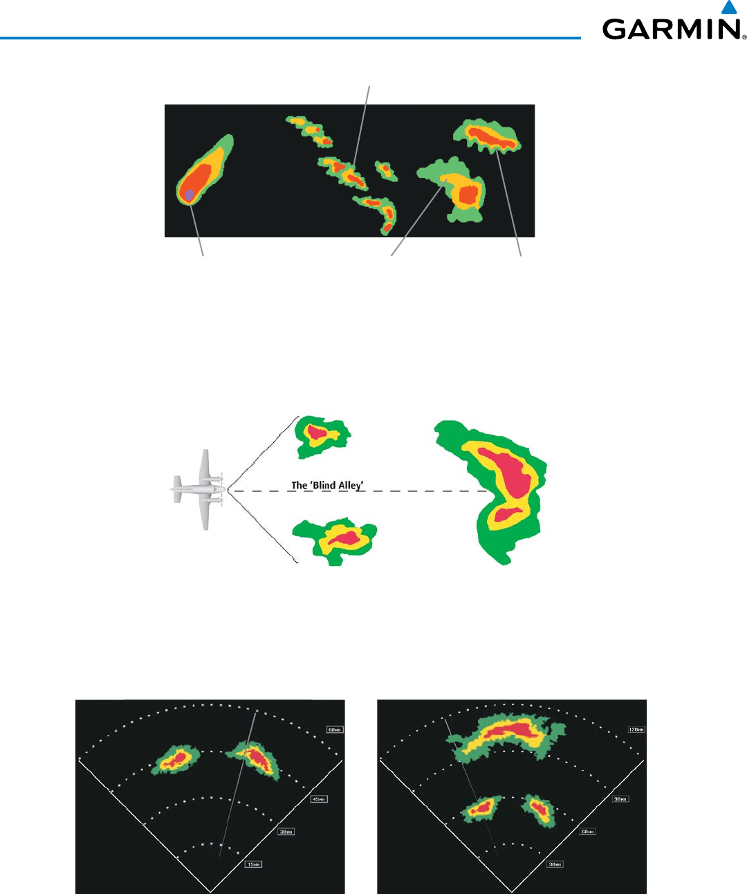
Garmin G1000 Pilot’s Guide for the Beechcraft 200/B200 Series
190-00928-04 Rev. A384
HAZARD AVOIDANCE
Figure 6-98 Cell Irregularities
Steep Gradient
Squall Line
Hook or Finger Scalloped Edge
Thunderstorm development is rapid. A course may become blocked within a short time. When displaying
shorter ranges, periodically select a longer range to see if problems are developing further out. That can
help prevent getting trapped in a blind alley or an area that is closed at one end by convective weather.
Figure 6-99 The Blind Alley - Horizontal Scan
In areas of multiple heavy cells, use the Vertical Scan feature along with antenna tilt management to
examine the areas. Remember to avoid shadowed areas behind targets.
Figure 6-100 The Blind Alley
The Blind Alley at Close Range The Large Storm Behind

190-00928-04 Rev. A
Garmin G1000 Pilot’s Guide for the Beechcraft 200/B200 Series
385
HAZARD AVOIDANCE
toRnaDoeS
There are no conclusive radar target return characteristics which identify a tornado. However, tornadoes
may be present if the following characteristics are observed:
• A narrow, finger-like portion extends and in a short time curls into a hook and closes on itself.
• A hook, which may be in the general shape of the numeral 6 (9 in the southern hemisphere), especially
if bright and projecting from the southwest quadrant (northeast quadrant in the southern hemisphere) of
a major thunderstorm.
• V-shaped notches.
• Doughnut shapes.
These shapes do not always indicate tornadoes, and tornado returns are not limited to these characteristics.
Confirmed radar observations of tornadoes most often have not shown shapes different from those of a
normal thunderstorm display.
Hail
Hail results from updrafts carrying water high enough to freeze. Therefore, the higher the top of a
thunderstorm, the greater the probability that it contains hail. Vertically scanning the target return can
give the radar top of a thunderstorm that contains hail. Radar top is the top of a storm cell as detected by
radar. It is not the actual top, or true top of the storm. The actual top of a storm cell is seen with the eyes
in clear air and may be much higher than the radar top. The actual top does not indicate the top of the
hazardous area.
Hail can fall below the minimum reflectivity threshold for radar detection. It can have a film of water on
its surface, making its reflective characteristics similar to a very large water droplet. Because of this film of
water, and because hail stones usually are larger than water droplets, thunderstorms with large amounts
of wet hail return stronger signals than those with rain. Some hail shafts are extremely narrow (100 yards
or less) and make poor radar targets. In the upper regions of a cell where ice particles are dry (no liquid
coating), target returns are less intense.
Hail shafts are associated with the same radar target return characteristics as tornados. U-shaped cloud
edges three to seven miles across can also indicate hail. These target returns appear quite suddenly along
any edge of the cell outline. They also change in intensity and shape in a matter of seconds, making vigilant
monitoring essential.
OPERATION IN WEATHER MODE
WARNING: Begin transmitting only when it is safe to do so. When transmitting while the aircraft is on the
ground, no personnel or objects should be within 11 feet of the antenna.
CAUTION: In Standby mode, the antenna is parked at the center line. It is always a good idea to put the
radar in Standby mode before taxiing the aircraft to prevent the antenna from bouncing on the bottom stop
and possibly causing damage to the radar assembly.
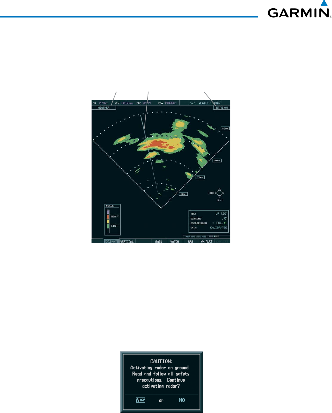
Garmin G1000 Pilot’s Guide for the Beechcraft 200/B200 Series
190-00928-04 Rev. A386
HAZARD AVOIDANCE
When the weather radar system is in the Weather or Ground Map mode, the system automatically switches
to Standby mode on landing.
In Reversionary mode, the weather radar system automatically switches to Standby mode. The system
remains in Standby mode until both displays are restored. In Reversionary mode, the weather radar system
cannot be controlled.
Figure 6-101 Horizontal Scan Display
Radar Mode Scan Line Antenna Stabilization Status
Displaying weather on the Weather Radar Page:
1) Select the Weather Radar Page in the Map Page Group with the
FMS
Knob.
2) Select the MODE Softkey.
3) While on the ground, select the STANDBY Softkey. For the GWX 68, a one-minute warm-up period is initiated
(countdown is displayed on the screen). After the warm-up is complete, the radar enters the Standby Mode. The
warm-up period is not applicable to the GWX 70.
a) Select the WEATHER Softkey. A confirmation window is displayed.
Figure 6-102 Confirming Activating Radar
(GWX 68 Only)
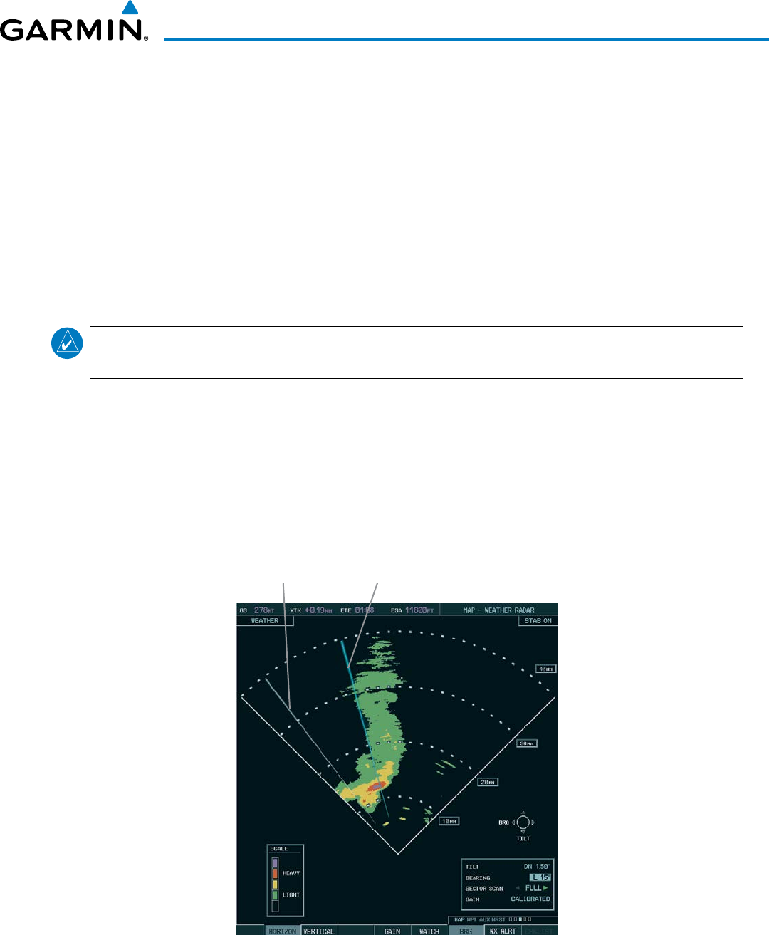
190-00928-04 Rev. A
Garmin G1000 Pilot’s Guide for the Beechcraft 200/B200 Series
387
HAZARD AVOIDANCE
b) Turn the small FMS Knob to highlight YES and press the ENT Key to continue radar activation.
OR:
If the aircraft is airborne, select the WEATHER Softkey. For the GWX 68, a one-minute warm-up period is
initiated (countdown is displayed on the screen). After the warm-up is complete, the radar begins transmitting.
The warm-up period is not applicable to the GWX 70.
4) Turn the RANGE Knob to select the desired map range.
5) The horizontal scan is initially displayed (Figure 6-101). If desired, select the VERTICAL Softkey to change to
vertical scanning.
Vertically scanning a storm cell:
NOTE: Vertical scanning of a storm cell should be done with the aircraft wings level to avoid constant
adjustment of the Bearing Line.
1) While in the Horizontal Scan view, select the BRG Softkey. This places the cursor in the BEARING field and
displays the Bearing Line.
If the Bearing Line is not displayed, press the MENU Key and turn the large
FMS Knob to select Show Bearing
Line. Press the ENT Key.
2) Press the ENT Key.
3) Turn the small
FMS Knob to place the Bearing Line on the desired storm cell or other area to be vertically
scanned.
Figure 6-103 Bearing Line on Horizontal Scan
Bearing Line
Scan Line
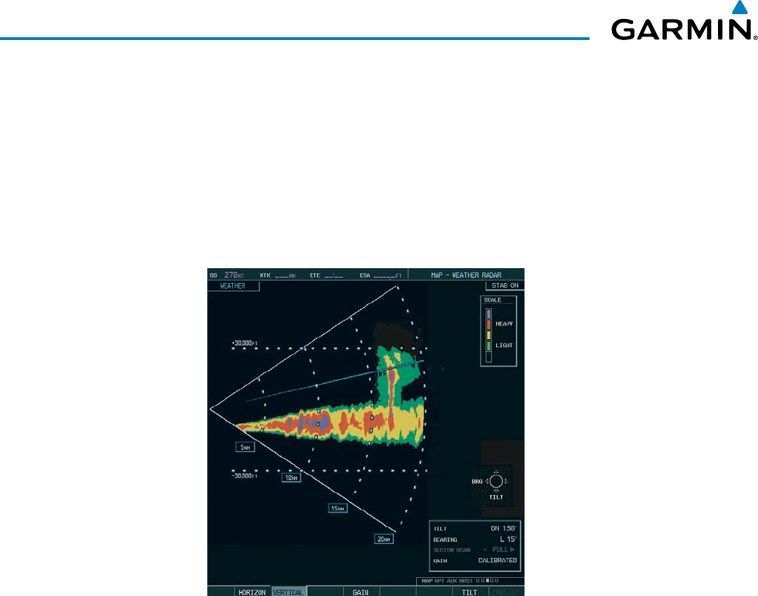
Garmin G1000 Pilot’s Guide for the Beechcraft 200/B200 Series
190-00928-04 Rev. A388
HAZARD AVOIDANCE
4) Select the
VERTICAL Softkey. A vertical scan of the selected area is now displayed (Figure 6-104).
5) The small
FMS Knob may be used to move the scanned bearing line a few degrees right or left.
6) Turn the RANGE Knob to adjust the range.
7) Press the FMS Knob to remove the cursor.
8) To select a new area to be vertically scanned, select the HORIZON Softkey to return to the Horizontal Scan view
and repeat the previous steps.
The RANGE Knob can also be used to adjust bearing from left to right.
Figure 6-104 Vertical Scan Display
aDjuSting antenna tilt angle
In order to make an accurate interpretation of a storm cell, the radar beam should be pointed at the wet
part of the weather cell to record the proper rainfall intensity (color level). The ideal aiming point is just
below the freezing level of the storm. The best way to find this point is to use the Vertical Scan feature. The
antenna tilt angle can be centered on the strongest return area in the vertical scan to get a more accurate
view of the coverage and intensity of the target in the horizontal scan.
Adjusting antenna tilt on the Horizontal Scan display:
1) Press the
FMS Knob to activate the cursor in the TILT field.
2) Turn the small
FMS Knob to select the desired antenna tilt angle.
3) Press the ENT Key.
4) Press the FMS Knob to remove the cursor.
The RANGE Knob can also be used to adjust tilt up and down.
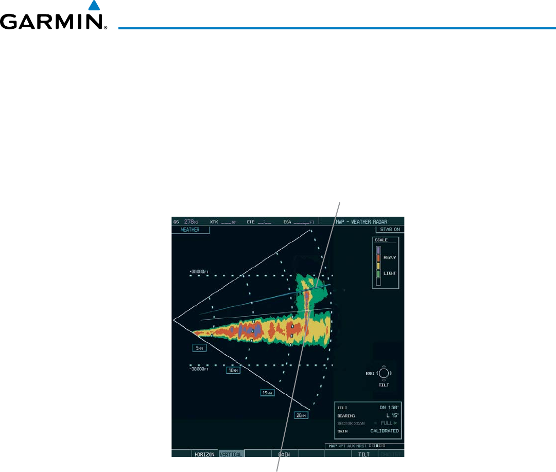
190-00928-04 Rev. A
Garmin G1000 Pilot’s Guide for the Beechcraft 200/B200 Series
389
HAZARD AVOIDANCE
Adjusting antenna tilt on the Vertical Scan display:
1) Select the
TILT Softkey to activate the cursor in the TILT field and display the Tilt Line.
If the Tilt Line is not displayed, press the MENU Key and turn the large
FMS Knob to select Show Tilt Line. Press
the ENT Key.
2) Turn the small
FMS Knob to adjust the antenna tilt angle. The selected tilt angle is implemented when Horizontal
Scan is again selected.
The RANGE Knob can also be used to adjust tilt.
Figure 6-105 Adjusting Tilt on Vertical Scan Display
Scan Line
Tilt Line
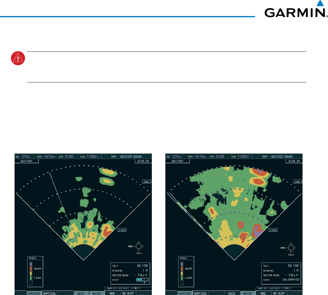
Garmin G1000 Pilot’s Guide for the Beechcraft 200/B200 Series
190-00928-04 Rev. A390
HAZARD AVOIDANCE
aDjuSting gain
WARNING: Changing the gain in weather mode causes precipitation intensity to be displayed as a color
not representative of the true intensity. Remember to return the gain setting to Calibrated for viewing the
actual intensity of precipitation.
1) Select the GAIN Softkey to activate the cursor in the GAIN field.
2) Turn the small FMS Knob to adjust the gain for the desirable level. The gain setting is visible in the GAIN field
as a movable horizontal bar in a flashing box. The line pointer is a reference depicting the calibrated position.
3) Press the FMS Knob to remove the cursor.
4) Select the GAIN Softkey again to recalibrate the gain. CALIBRATED is displayed in the GAIN field.
Calibrated GainManual Gain Set Below Calibrated
Figure 6-106 Gain Calibration
SectoR Scan
1) While in horizontal scan mode, select the BRG Softkey to display the Bearing Line and place the cursor in the
BEARING field. If the Bearing Line is not displayed, press the MENU Key and turn the large
FMS Knob to select
Show Bearing Line.
2) Press the ENT Key.
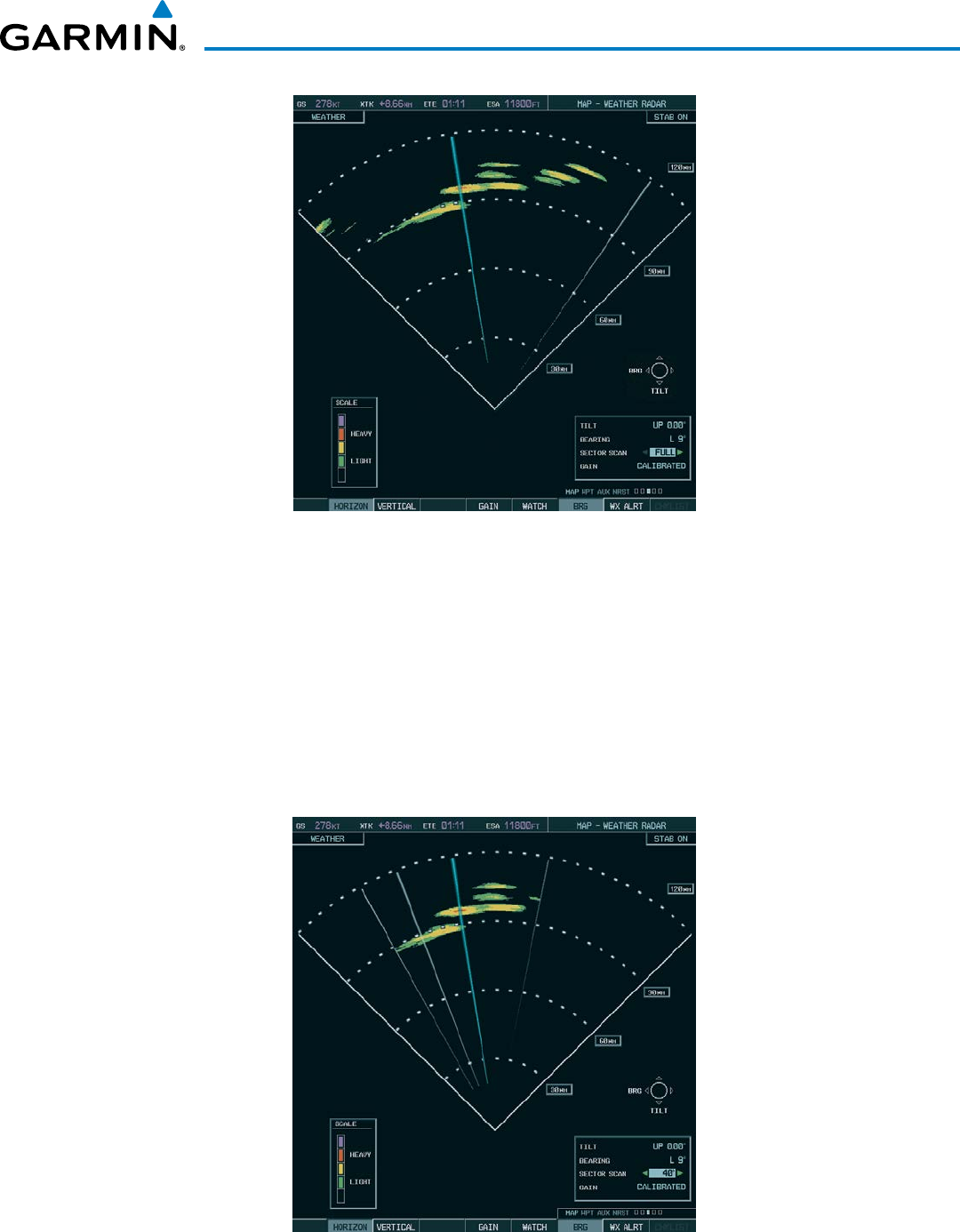
190-00928-04 Rev. A
Garmin G1000 Pilot’s Guide for the Beechcraft 200/B200 Series
391
HAZARD AVOIDANCE
Figure 6-107 Selecting Sector Scan Position
3) Turn the small
FMS Knob to place the Bearing Line in the desired position. The location of the Bearing Line
becomes the center point of the Sector Scan.
4) Turn the large
FMS Knob to place the cursor in the SECTOR SCAN field.
5) Turn the small
FMS Knob to highlight the desired scan. Selecting ‘FULL’ enables a 90º scan (GWX 68) or 120º
scan (GWX 70).
6) If desired, readjust the Bearing Line as discussed previously to change the center of the Sector Scan.
7) Select the BRG Softkey again to remove the Bearing Line and cursor. The bearing reference is reset to 0º.
Figure 6-108 40˚ Sector Scan
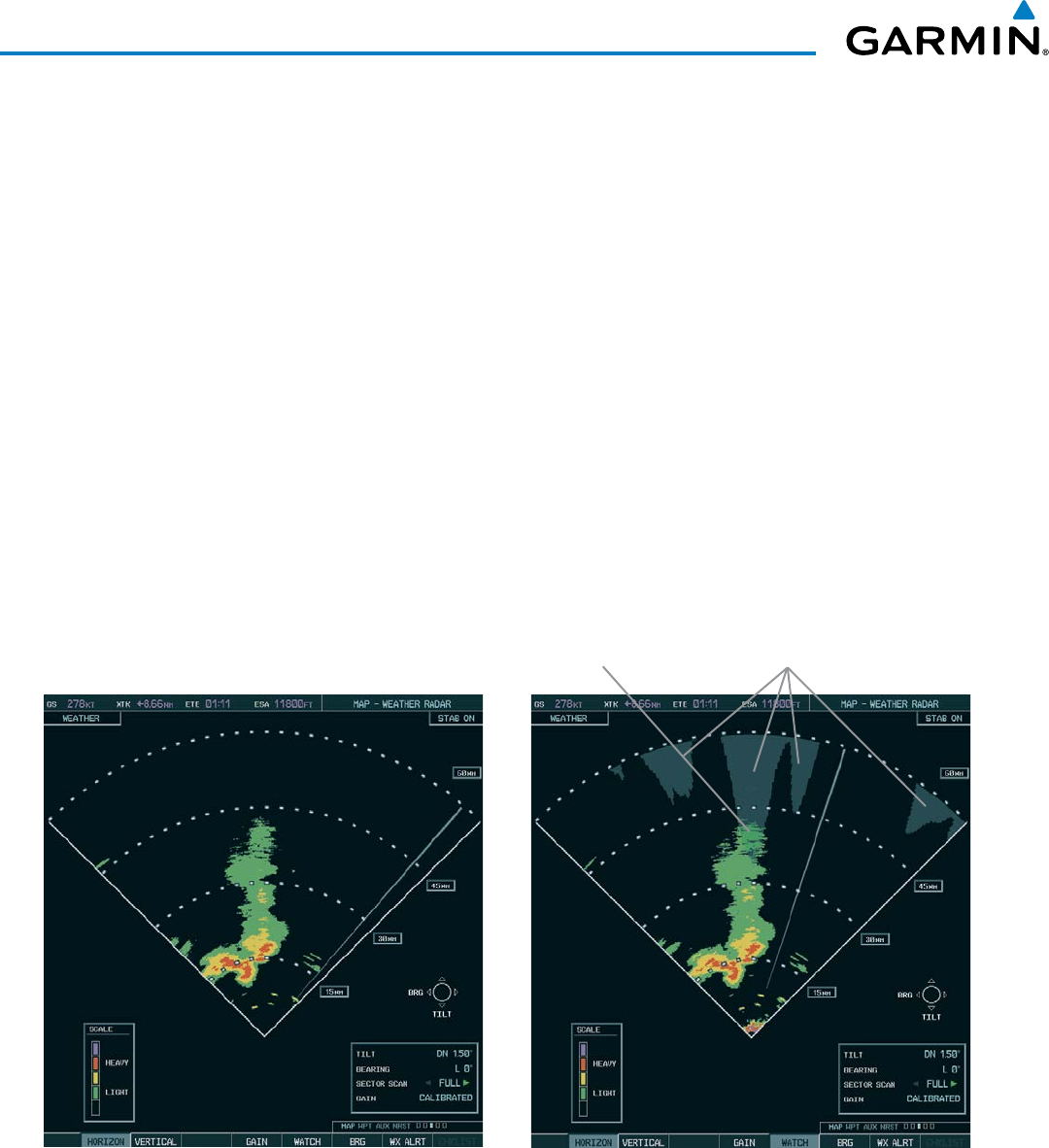
Garmin G1000 Pilot’s Guide for the Beechcraft 200/B200 Series
190-00928-04 Rev. A392
HAZARD AVOIDANCE
antenna StaBilization
1) To activate or deactivate the antenna stabilization, select the MODE Softkey.
2) Select the STAB ON Softkey to activate antenna stabilization or select the STAB OFF Softkey to deactivate. The
current stabilization condition is shown in the upper right of the weather radar display.
WeatHeR attenuateD coloR HigHligHt (WatcH™)
While in horizontal scan mode, this feature can be used as a tool to determine areas of possible inaccuracies
in displayed intensity due to weakening of the radar energy. This weakening is known as attenuation. The
radar energy weakens as it passes through areas of intense precipitation, large areas of lesser precipitation,
and distance. Issues with the radome also attenuates the radar energy. All these factors have an effect on the
return intensity. The more energy that dissipates, the lesser the displayed intensity of the return. Accuracy
of the displayed intensity of returns located in the shaded areas are suspect. Make maneuvering decisions
with this information in mind. Proper antenna tilt management should still be employed to determine the
extent of attenuation in a shaded area.
To activate or deactivate the WATCH™ feature, select the WATCH Softkey.
Horizontal Scan With WATCH™Horizontal Scan Without WATCH™
Areas of
Attenuated Signal
Displayed intensity is questionable.
Potentially stronger than displayed.
Figure 6-109 Horizontal Scan Without and With WATCH™
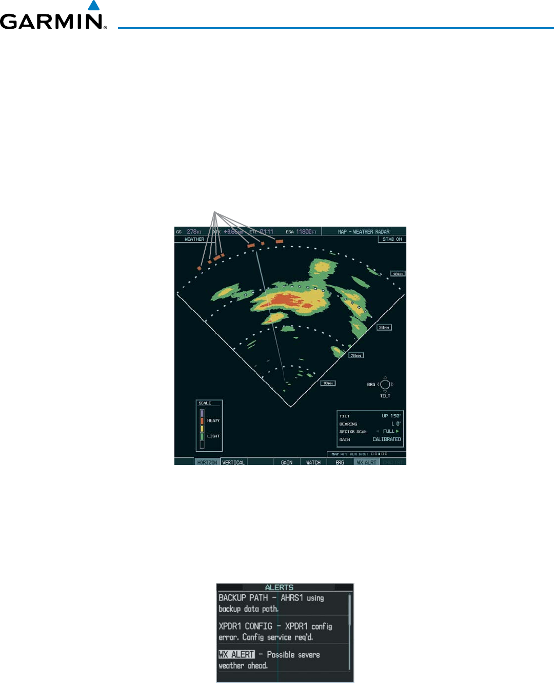
190-00928-04 Rev. A
Garmin G1000 Pilot’s Guide for the Beechcraft 200/B200 Series
393
HAZARD AVOIDANCE
WeatHeR aleRt
The Weather Alert feature indicates the presence of heavy precipitation between the ranges of 80 and 320
nm regardless of the currently displayed range. Weather Alert targets appear as red bands along the outer
range ring at the approximate azimuth of the detected returns.
If a Weather Alert is detected within ±10° of the aircraft heading, and the WX ALRT Softkey is enabled
on the Weather Radar Page, the system also displays an alert on the PFD in the Alerts Window.
If the antenna tilt is adjusted too low, a weather alert can be generated by ground returns. To avoid
unwanted weather alerts, deselect the WX ALRT Softkey..
Figure 6-110 Weather Alert Targets on the
Weather Radar Page
Weather Alert Targets
To enable or disable the Weather Alerts which appear in the Alerts Window on the PFD, select the WX
ALRT Softkey. The system continues to display weather alert target bands on the Weather Radar Page even
if the PFD alert message is disabled.
Figure 6-111 Weather Alert on PFD
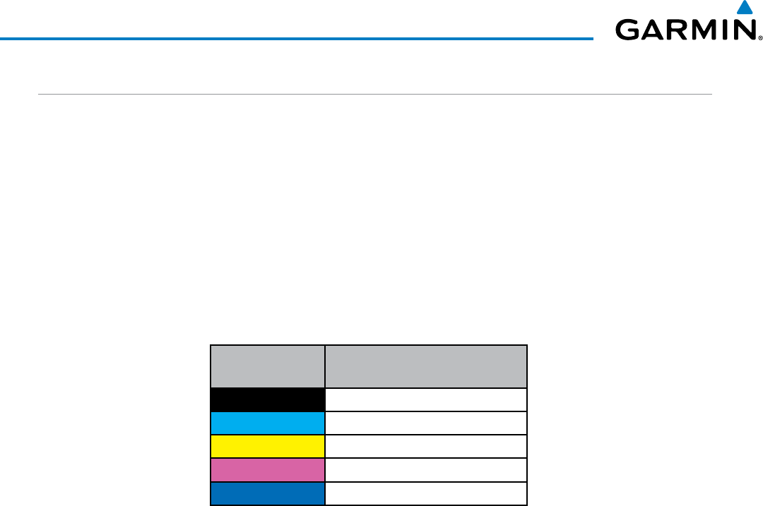
Garmin G1000 Pilot’s Guide for the Beechcraft 200/B200 Series
190-00928-04 Rev. A394
HAZARD AVOIDANCE
GROUND MAPPING AND INTERPRETATION
A secondary use of the weather radar system is for the presentation of terrain. This can be a useful tool for
verifying aircraft position. A picture of the ground is represented much like a topographical map that can be
used as a supplement to the navigation map on the MFD.
Ground Map mode uses a different gain range than Weather mode. Different colors are also used to represent
the intensity levels. The displayed intensity of ground target returns are defined in the table below. Use of the
GAIN and TILT controls help improve contrast so that specific ground targets can be recognized more easily.
As previously discussed, the type and orientation of the target in relation to the aircraft affects the intensity
displayed.
When the weather radar system is in either the Weather or Ground Map mode, the system automatically
switches to Standby mode upon landing.
Ground Map
Mode Color Intensity
Black
0 dB
Cyan
> 0 dB to < 9 dB
Yellow
9 dB to < 18 dB
Magenta
18 dB to < 27 dB
Blue
27 dB and greater
Table 6-10 Ground Target Return Intensity Levels
Operation in Ground Map Mode:
1) Select the
MODE Softkey.
2) Select the GROUND Softkey to place the radar in Ground Map mode.
3) Select the BACK Softkey.
4) Press the FMS Knob to activate the cursor.
5) Turn the large
FMS Knob to place the cursor in the TILT field.
6) Adjust the antenna tilt angle by turning the small
FMS Knob to display ground returns at the desired distance.
7) Press the FMS Knob to remove the cursor.
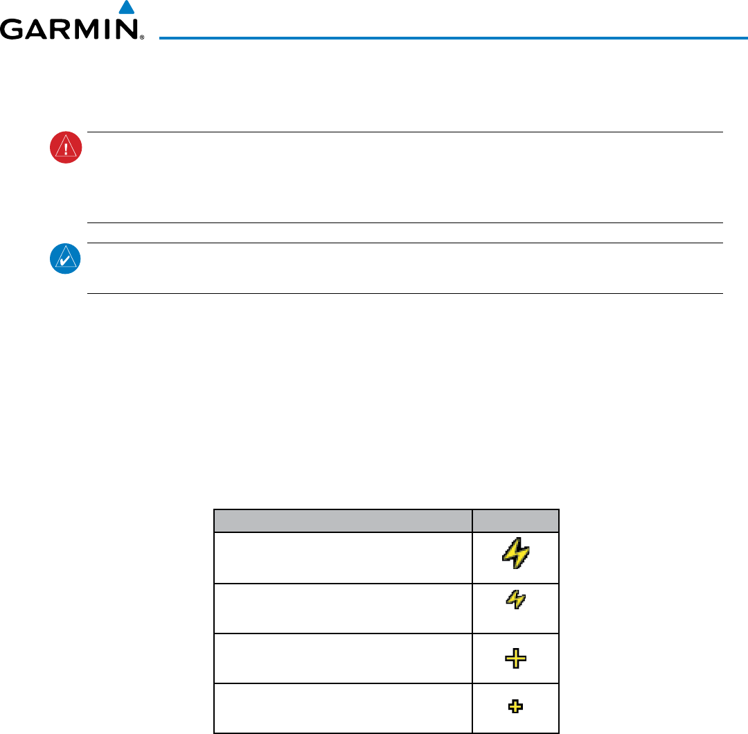
190-00928-04 Rev. A
Garmin G1000 Pilot’s Guide for the Beechcraft 200/B200 Series
395
HAZARD AVOIDANCE
6.4 STORMSCOPE
WARNING: Do not rely on information from the lightning detection system display as the sole basis for
hazardous weather avoidance. Range limitations and interference may cause the system to display inaccurate
or incomplete information. Refer to documentation from the lightning detection system manufacturer for
detailed information about the system.
NOTE: Stormscope lightning information cannot be displayed simultaneously on the same map as lightning
information from data link lightning sources.
The MAP - Stormscope Page is the principal map page for viewing Stormscope data. The following pages can
also display Stormscope data as an additional reference:
• PFD Inset Map • AUX - Trip Planning Page
• Navigation Map • Nearest Pages
To display Stormscope data on any map besides the Stormscope Page, select the
MAP
Softkey (or the INSET
Softkey for the PFD Inset Map), then select the
STRMSCP
Softkey. These pages can also display cell or strike data
using the yellow lightning strike symbology shown in Table 6-11.
Lightning Age Symbol
Strike is less than 6 seconds old
Strike is between 6 and 60 seconds old
Strike is between 1 and 2 minutes old
Strike is between 2 and 3 minutes old
Table 6-11 Lightning Age and Symbols
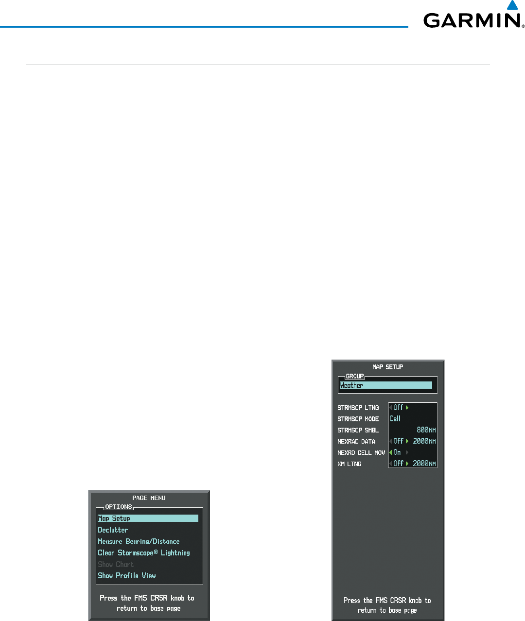
Garmin G1000 Pilot’s Guide for the Beechcraft 200/B200 Series
190-00928-04 Rev. A396
HAZARD AVOIDANCE
SETTING UP STORMSCOPE ON THE NAVIGATION MAP
Setting up Stormscope options on the Navigation Map:
1) On the Navigation Map Page, press the MENU Key.
2) With ‘Map Setup’ selected (Figure 6-112), press the ENT Key.
3) Turn the small FMS Knob to display the group selection window. Turn the small FMS Knob to select ‘Weather’,
and press the ENT Key.
4) Turn the large FMS Knob to highlight and move between the product selections (Figure 6-113).
5) When an item is highlighted, turn the small FMS Knob to select the option.
6) Press the ENT Key.
7) Press the
FMS
Knob to return to the Navigation Map Page (Figure 6-114).
The following options are available (Figure 6-113):
• STRMSCP LTNG – Turns the display of Stormscope data on or off.
• STRMSCP MODE – Selects the CELL or STRIKE mode of lightning activity. Cell mode identifies clusters
or cells of electrical activity. Strike mode indicates the approximate location of lightning strikes.
• STRMSCP SMBL – Selects the range at which Stormscope data displays. Stormscope data is removed
when a map range greater than the STRMSCP SMBL value is selected.
Figure 6-112 Navigation Map Page Menu Figure 6-113 Map Setup Menu
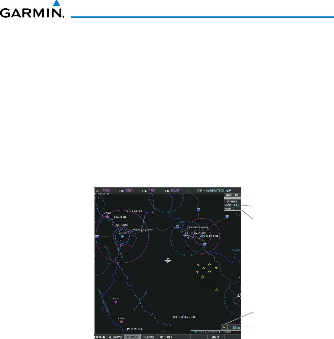
190-00928-04 Rev. A
Garmin G1000 Pilot’s Guide for the Beechcraft 200/B200 Series
397
HAZARD AVOIDANCE
CELL AND STRIKE MODE ON THE NAVIGATION MAP
On the Navigation Map, cell mode identifies cells of lightning activity (Figure 6-114). Stormscope identifies
clusters of electrical activity that indicate cells. Strike mode indicates the approximate location of lightning
strikes.
Selecting the ‘cell’ or ‘strike’ mode on the Navigation Map:
1) Press the MENU Key.
2) With ‘Map Setup’ selected, press the ENT Key (Figure 6-112).
3) Select the ‘Weather’ group.
4) Press the ENT Key. The cursor flashes on ‘STRMSCP LTNG’.
5) Turn the
large FMS
Knob to select ‘STRMSCP MODE’.
6) Turn the small FMS Knob to change between ‘CELL’ and ‘STRIKE’ options. When an item is selected, press the
ENT Key.
7) Press the
FMS
knob to return to the Navigation Map Page.
Figure 6-114 Navigation Map Page with Stormscope
Lightning Data
Map
Orientation
Stormscope
Mode
Strike Rate
per Minute
Stormscope
Icon
80 nm Map
Range
If heading input is lost, strikes and/or cells must be cleared manually after the execution of each turn. This
is to ensure that the strike and/or cell positions are depicted accurately in relation to the nose of the aircraft.
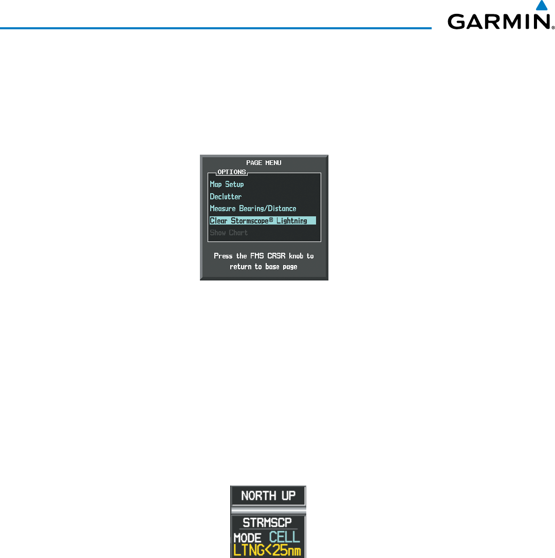
Garmin G1000 Pilot’s Guide for the Beechcraft 200/B200 Series
190-00928-04 Rev. A398
HAZARD AVOIDANCE
Manually clearing Stormscope data on the Navigation Map:
1) Press the
MENU
Key.
2) Select ‘Clear Stormscope® Lightning’ (Figure 6-115).
3) Press the
ENT
Key.
Figure 6-115 Navigation Map Page Options Menu
ZOOM RANGE ON THE NAVIGATION MAP
Stormscope lightning data can be displayed up to 800 nm zoom range (in North Up orientation) on the
Navigation Map Page.
However, in Track Up orientation at the 500 nm range, a portion of Stormscope lightning
data can be behind the aircraft and therefore not visible on the Navigation Map
. Since the range for Stormscope
data is 400 nm diameter total (200 nm in front and 200 nm behind), the 500 nm range in North Up orientation
shows all the data.
At a map range of less than 25 nm, Stormscope lightning data is not displayed, but can still be present. The
presence of Stormscope lightning data is indicated by the annunciation ‘LTNG < 25 nm’ in the upper right
corner (Figure 6-116).
Figure 6-116 Lightning Display Range Annunciation
Selecting a Stormscope range on the Navigation Map:
1) Press the MENU Key.
2) Select ‘MAP SETUP’.
3) Select the ‘Weather’ group.
4) Press the ENT Key.
5) Turn the
large FMS
Knob to select ‘STRMSCP SMBL’.
6) Turn the
small FMS
Knob to select the maximum display range.
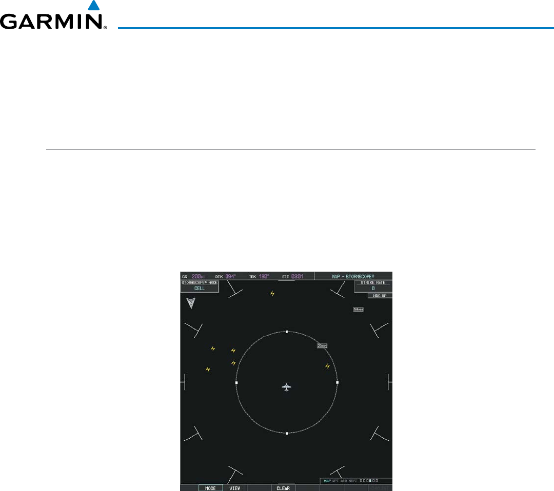
190-00928-04 Rev. A
Garmin G1000 Pilot’s Guide for the Beechcraft 200/B200 Series
399
HAZARD AVOIDANCE
7) Press the
ENT
Key.
8) Press the
FMS
Knob to return to the Navigation Map Page.
To change the display range on the Navigation Map Page, turn the RANGE Knob clockwise to zoom out or
counter-clockwise to zoom in.
SELECTING THE STORMSCOPE PAGE
Stormscope lightning data can be displayed at the ranges of 25 nm, 50 nm, 100 nm, and 200 nm.
Adjusting the Stormscope Map Range:
1) Turn the large
FMS
Knob to select the Map Page Group.
2) Turn the small
FMS
Knob
to select the Stormscope Page.
3) To change the map range, turn the RANGE Knob clockwise to zoom out or counter-clockwise to zoom in.
Figure 6-117 Stormscope Page
Changing between ‘cell’ and ‘strike’ mode:
1) Select the Stormscope Page.
2) Select the
MODE
Softkey. The
CELL
and
STRIKE
softkeys are displayed.
3) Select the
CELL
Softkey to display ‘CELL’ data or select the
STRIKE
Softkey to display ‘STRIKE’ data. ‘CELL’ or
‘STRIKE’ is displayed in the mode box in the upper left corner of the Stormscope Page.
4) Press the
BACK
Softkey to return to the Stormscope Page.
Or:
1) Select the Stormscope Page.
2) Press the MENU Key.
3) Turn the
small
FMS Knob to choose between ‘CELL’ and ‘STRIKE’ options.
4) When an item is selected, press the ENT Key.
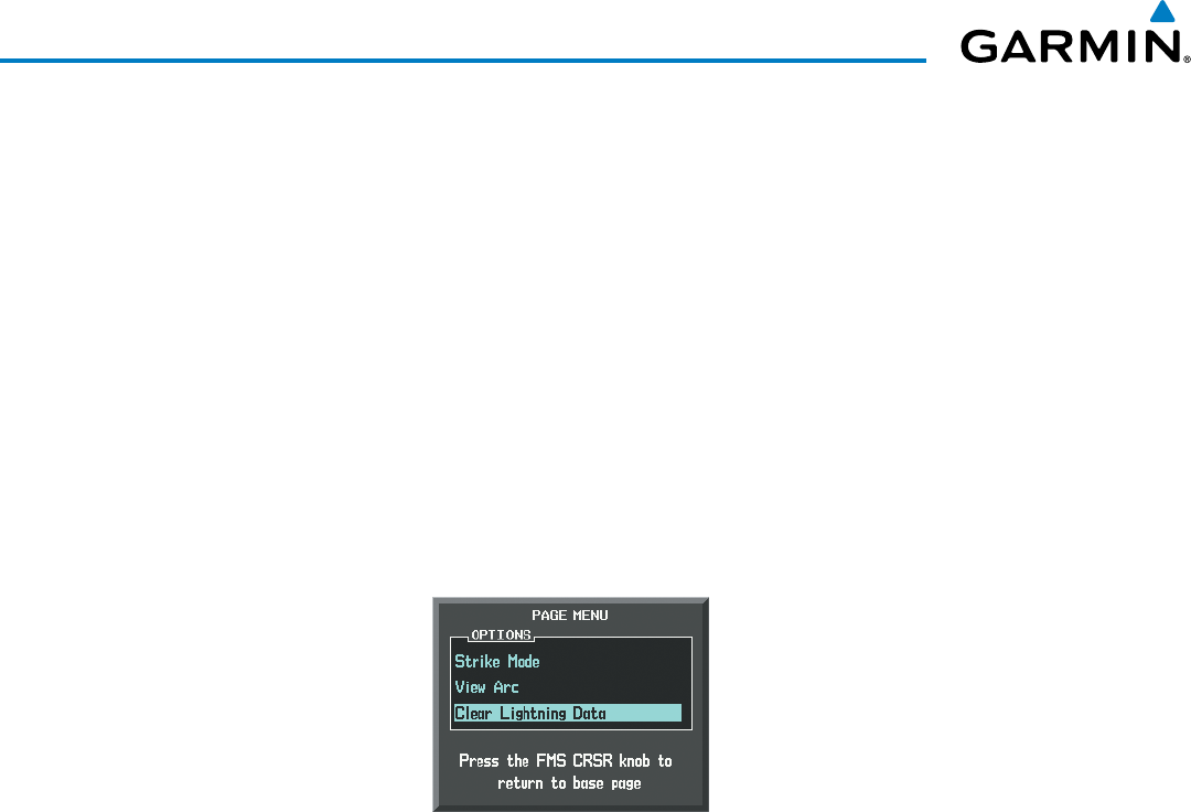
Garmin G1000 Pilot’s Guide for the Beechcraft 200/B200 Series
190-00928-04 Rev. A400
HAZARD AVOIDANCE
If heading input is lost, strikes and/or cells must be cleared manually after the execution of each turn
(Figure 6-118). This is to ensure that the strike and/or cell positions are depicted accurately in relation to the
nose of the aircraft.
Manually clearing Stormscope data (on the Stormscope Page):
1) Select the Stormscope Page.
2) Press the
MENU
Key.
3) Select ‘Clear Lightning Data’ (Figure 6-118).
4) Press the
ENT
Key.
Or:
1) Select the Stormscope Page.
2) Select the CLEAR Softkey.
Figure 6-118 Navigation Map Page Options Menu
Changing the viewing mode between 360˚ and 120˚:
1) Select the Stormscope Page.
2) Press the
VIEW
Softkey. The
360
and
ARC
softkeys are displayed.
3) Press the 360 Softkey to display a 360˚ viewing area or select the ARC Softkey to display a 120˚ viewing area.
4) Press the
BACK
Softkey to return to the Stormscope Page.
Or:
1) Select the Stormscope Page.
2) Press the MENU Key.
3) Turn the
small
FMS Knob to choose between ‘View Arc’ and ‘View 360˚ options.
4) When an item is selected, press the ENT Key.

190-00928-04 Rev. A
Garmin G1000 Pilot’s Guide for the Beechcraft 200/B200 Series
401
HAZARD AVOIDANCE
6.5 TAWS-B
WARNING: Do not use TAWS-B information for primary terrain avoidance. TAWS-B is intended only to
enhance situational awareness.
NOTE: Terrain data is not displayed if the aircraft is out of the installed terrain database coverage area.
NOTE: The data contained in the TAWS-B databases comes from government agencies. Garmin accurately
processes and cross-validates the data but cannot guarantee the accuracy and completeness of the data.
TAWS-B (Terrain Awareness and Warning System - Class B) is an optional feature to increase situational
awareness and aid in reducing controlled flight into terrain (CFIT). TAWS-B provides visual annunciations and
voice alerts when terrain and obstacles are within the given altitude threshold from the aircraft. The displayed
alerts and warnings are advisory in nature only.
TAWS-B satisfies TSO-C151b Class B requirements for certification.
TAWS-B requires the following to operate properly:
• A valid terrain/obstacle/airport terrain database
• A valid 3-D GPS position solution
TAWS-B uses terrain and obstacle information supplied by government sources. Terrain information is based
on terrain elevation information in a database that may contain inaccuracies. Individual obstructions may be
shown if available in the database. Garmin verifies the data to confirm accuracy of the content, per TSO-C151b.
However, the displayed information should never be understood as being all-inclusive and data may still contain
inaccuracies.
TAWS-B uses information provided from the GPS receiver to provide a horizontal position and altitude. GPS
altitude is derived from satellite measurements. GPS altitude is then converted to the height above geodetic sea
level (GSL), which is the height above mean sea level (MSL) calculated geometrically. GSL altitude is used to
determine TAWS-B alerts. GSL altitude accuracy is affected by satellite geometry, but is not subject to variations
in pressure and temperature that normally affect pressure altitude sensors. GSL altitude does not require local
altimeter settings to determine MSL altitude. It is a widely-used MSL altitude source. Therefore, GSL altitude
provides a highly accurate and reliable MSL altitude source to calculate terrain and obstacle alerts.
The terrain and obstacle databases used by TAWS-B are referenced to MSL. Using the GPS position and GSL
altitude, TAWS-B displays a 2-D picture of the surrounding terrain and obstacles relative to the position and
altitude of the aircraft. Furthermore, the GPS position and GSL altitude are used to calculate and “predict” the
aircraft’s flight path in relation to the surrounding terrain and obstacles. In this manner, TAWS-B can provide
advanced alerts of predicted dangerous terrain conditions.
Baro-corrected altitude (or indicated altitude) is derived by adjusting the altimeter setting for local atmospheric
conditions. The most accurate baro-corrected altitude can be achieved by frequently updating the altimeter
setting to the nearest reporting station along the flight path. However, because actual atmospheric conditions
seldom match the standard conditions defined by the International Standard Atmosphere (ISA) model (where
pressure, temperature, and lapse rates have fixed values), it is common for the baro-corrected altitude (as read
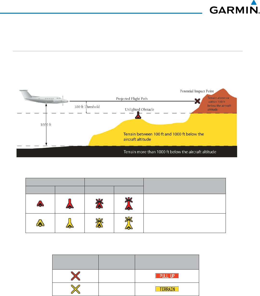
Garmin G1000 Pilot’s Guide for the Beechcraft 200/B200 Series
190-00928-04 Rev. A402
HAZARD AVOIDANCE
from the altimeter) to differ from the GSL altitude. This variation results in the aircraft’s GSL altitude differing
from the baro-corrected altitude.
DISPLAYING TAWS-B DATA
TAWS-B uses yellow (caution) and red (warning) to depict terrain and obstacles (with heights greater than
200 feet above ground level, AGL) alerts relative to aircraft altitude. Colors are adjusted automatically as the
aircraft altitude changes. The colors and symbols in figure and tables below are used to represent terrain,
obstacles, and potential impact points.
Figure 6-119 Terrain Altitude/Color Correlation for TAWS-B
Unlighted Obstacle Lighted Obstacle Obstacle Location
< 1000’ AGL > 1000’ AGL < 1000’ AGL > 1000’ AGL
Red obstacle is above or within 100 ft
below the aircraft altitude
Yellow obstacle is between 100 ft and
1000 ft below the aircraft altitude
Table 6-12 TAWS-B Obstacle Colors and Symbology
Potential Impact
Point Symbol Alert Type Example Annunciation
Warning
Caution
Table 6-13 TAWS-B Potential Impact Point Symbols with Alert Types
The Map - TAWS-B Page is the principal map page for viewing TAWS-B information. TAWS-B information
can be also displayed on the following maps and pages as an additional reference:
• PFD Inset Map
• Navigation Map Page
• Trip Planning Page
• Flight Plan Page

190-00928-04 Rev. A
Garmin G1000 Pilot’s Guide for the Beechcraft 200/B200 Series
403
HAZARD AVOIDANCE
Displaying terrain and obstacle information (maps other than the TAWS-B Page):
1) Select the MAP Softkey (for the PFD Inset Map, press the INSET Softkey).
2) Select the TERRAIN Softkey to display terrain and obstacle data.
When TAWS-B is selected on maps other than the TAWS-B Page, an icon to indicate the feature is enabled
for display and a legend for TAWS-B terrain colors are shown (Figure 6-126). The legend appears without the
icon on the TAWS-B Page.
The Navigation Map Page Setup Menu provides a means in addition to the softkeys for enabling/disabling the
display of terrain and obstacles. The setup menu also controls the map range settings above which terrain and
obstacle data are decluttered from the display. If a map range larger than the map range setting is selected, the
data is removed from the map. For terrain data, the enable/disable function applies only to the MFD, while the
range setting also affects the PFD Inset Map.
Terrain data can be selected for display independently of obstacle data; however, obstacles for which warnings
and cautions are issued are shown when terrain is selected for display and the map range is within the setting
limit.
Maps besides the TAWS-B Page use settings based on those selected for the Navigation Map Page. The
maximum display ranges for obstacles on each map are dependent on the range setting made for the Navigation
Map. If the maximum range for obstacle display on the Navigation Map is adjusted to below 20 nm, the highest
obstacle display range settings on the other applicable maps are also adjusted proportionally.
Customizing terrain and obstacle display on the Navigation Map Page:
1) Select the Navigation Map Page.
2) Press the MENU Key.
3) With ‘Map Setup’ highlighted, press the
ENT
Key (Figure 6-120).
4) Turn the small FMS Knob to select the ‘Map’ Group and press the ENT Key (Figure 6-121).
5) Turn the large
FMS
Knob or press the
ENT
Key to scroll through product selections (Figure 6-122).
• TERRAIN DATA – Turns the display of terrain data on or off and sets maximum range at which terrain is shown
• OBSTACLE DATA – Turns the display of obstacle data on or off and sets maximum range at which obstacles are shown
6) Turn the small
FMS
Knob to scroll through options for each product (ON/OFF, range settings).
7) Press the
ENT
Key to select an option.
8) Press the FMS Knob or CLR Key to return to the Navigation Map Page with the changed settings.
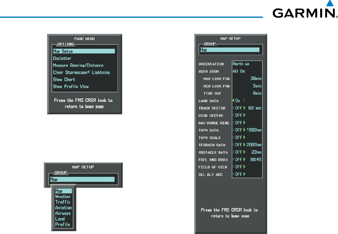
Garmin G1000 Pilot’s Guide for the Beechcraft 200/B200 Series
190-00928-04 Rev. A404
HAZARD AVOIDANCE
Figure 6-121 Navigation Map Page Setup Menu
Figure 6-120 Navigation Map Page Menu
Figure 6-122 Navigation Map Page Setup Menu, Map Group
TAWS-B PAGE
The TAWS-B Page is specialized to show terrain, obstacle, and potential impact point data in relation to
the aircraft’s current altitude, without clutter from the basemap. It is the principal page for viewing TAWS-B
information. Aviation data (airports, VORs, and other NAVAIDs) can be enabled for reference. If an obstacle
and the projected flight path of the aircraft intersect, the display automatically zooms in to the closest potential
point of impact on the TAWS-B Page.
Aircraft orientation on this map is always heading up unless there is no valid heading. Two views are available
relative to the position of the aircraft: the 360° default display and the radar-like ARC (120°) display. Map range
is adjustable with the RANGE Knob from 1 to 200 nm, as indicated by the map range rings (or arcs).
Displaying the TAWS-B Page:
1) Turn the large
FMS
Knob to select the Map Page Group.
2) Turn the small
FMS
Knob
to select the TAWS-B Page.
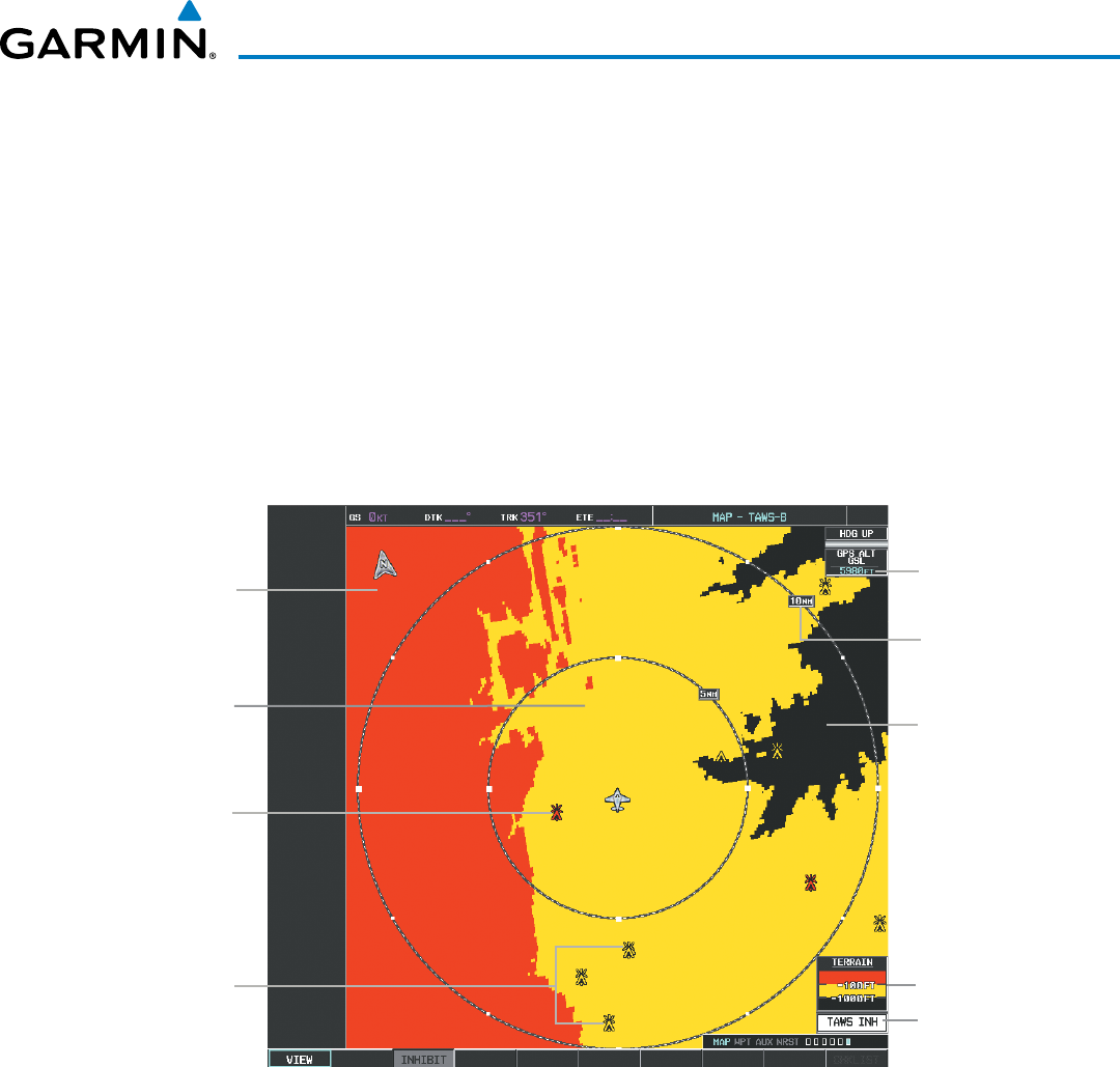
190-00928-04 Rev. A
Garmin G1000 Pilot’s Guide for the Beechcraft 200/B200 Series
405
HAZARD AVOIDANCE
Changing the TAWS-B Page view:
1) Select the
VIEW
Softkey.
2) Select the 360 or ARC Softkey to select the desired view.
Or:
1) Press the MENU Key.
2)
Select ‘View Arc or ‘View 360º’ (choice dependent on current state) and press the ENT Key to change the view
Showing/hiding aviation information on the TAWS-B Page:
1) Press the MENU Key.
2) Select ‘Show Aviation Data’ or ‘Hide Aviation Data’ (choice dependent on current state) and press the ENT Key.
Figure 6-123 TAWS-B Page, 360º View
Yellow Terrain
(Caution - Terrain
Between 100’ and
1000’ Below the
Aircraft Altitude)
Red Terrain
(Warning - Terrain
Above or Within
100’ Below the
Aircraft Altitude)
Terrain Legend
Map Range
Black Terrain
(Terrain More than
1000’ Below the
Aircraft Altitude)
Annunciation Window
Red Lighted
Obstacle is Above
or Within 100’
Below Aircraft
Altitude
Yellow Lighted
Obstacles are
Between 100’
and 1000’ Below
Aircraft Altitude
Current
Aircraft GPS-
derived GSL
Altitude
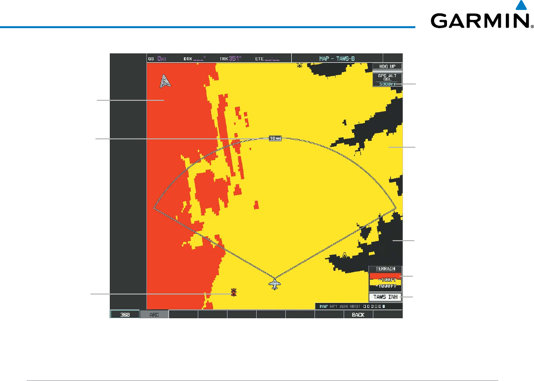
Garmin G1000 Pilot’s Guide for the Beechcraft 200/B200 Series
190-00928-04 Rev. A406
HAZARD AVOIDANCE
Figure 6-124 TAWS-B Page (ARC View)
Terrain Legend
Annunciation Window
Arc Range
Red Terrain
(Warning - Terrain
Above or Within
100’ Below the
Aircraft Altitude)
Current
Aircraft GPS-
derived GSL
Altitude
Red Lighted
Obstacle is Above
or Within 100’
Below Aircraft
Altitude
Yellow Terrain
(Caution - Terrain
Between 100’ and
1000’ Below the
Aircraft Altitude)
Black Terrain
(Terrain More than
1000’ Below the
Aircraft Altitude)
TAWS-B ALERTS
Alerts are issued when flight conditions meet parameters that are set within TAWS-B software algorithms.
TAWS-B alerts typically employ a CAUTION or a WARNING alert severity level, or both. When an alert is
issued, the system displays visual annunciations with voice alerts. Table 6-14 shows TAWS-B alert types with
corresponding annunciations and voice alerts.
When an alert occurs, the system displays annunciations on the PFDs and MFD. The TAWS-B Alert
Annunciation is shown to the upper left of the Altimeter on the PFDs and below the Terrain Legend on the
MFD. If the TAWS-B Page is not displayed at the time of the alert, a pop-up alert appears on the MFD. When
a pop-up alert occurs, do one of the following:
• Press the CLR Key (removes the pop-up alert), or
• Press the ENT Key (accesses the TAWS-B Page)
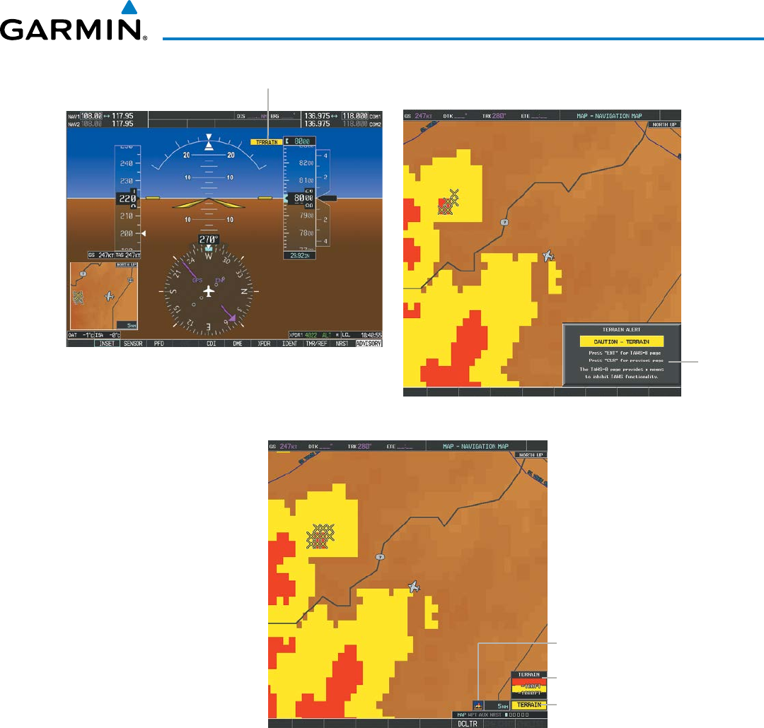
190-00928-04 Rev. A
Garmin G1000 Pilot’s Guide for the Beechcraft 200/B200 Series
407
HAZARD AVOIDANCE
Figure 6-125 TAWS-B Alert Annunciations
PFD Alert Annunciation
MFD
Pop-
Up
Alert
Figure 6-126 Navigation Map Page with Terrain data
(After removing TAWS-B Pop-Up alert)
Alert Annunciation
Terrain Legend
Terrain Display Enabled
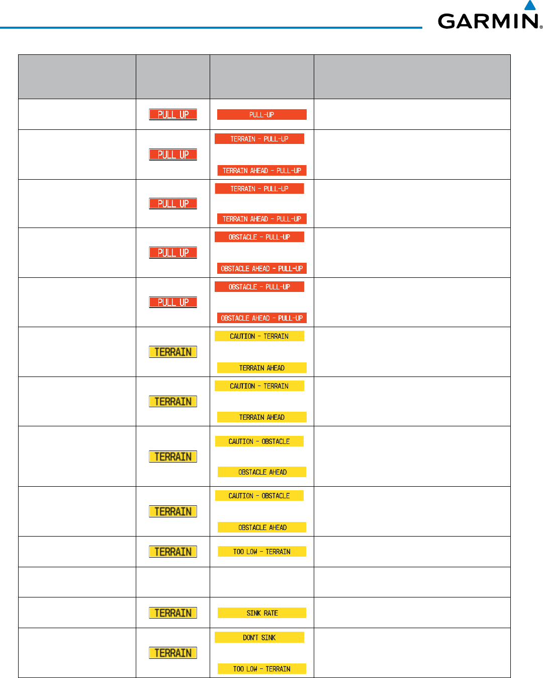
Garmin G1000 Pilot’s Guide for the Beechcraft 200/B200 Series
190-00928-04 Rev. A408
HAZARD AVOIDANCE
Alert Type
PFD/MFD**
Alert
Annunciation
MFD Pop-Up Alert
(except TAWS-B Page) Voice Alert
Excessive Descent Rate
Warning (EDR) “Pull-Up”
Reduced Required Terrain
Clearance Warning (RTC)
*
or
“Terrain, Terrain; Pull-Up, Pull-Up”*
or
“Terrain Ahead, Pull-Up; Terrain Ahead, Pull-Up”
Imminent Terrain Impact
Warning (ITI)
*
or
“Terrain, Terrain; Pull-Up, Pull-Up”*
or
“Terrain Ahead, Pull-Up; Terrain Ahead, Pull-Up”
Reduced Required Obstacle
Clearance Warning (ROC)
*
or
“
Obstacle, Obstacle; Pull-Up, Pull-Up
”*
or
“
Obstacle Ahead, Pull-Up; Obstacle Ahead, Pull-Up
”
Imminent Obstacle Impact
Warning (IOI)
*
or
“Obstacle, Obstacle; Pull-Up, Pull-Up”*
or
“Obstacle Ahead, Pull-Up; Obstacle Ahead, Pull-Up”
Reduced Required Terrain
Clearance Caution (RTC)
*
or
“Caution, Terrain; Caution, Terrain”*
or
“Terrain Ahead; Terrain Ahead”
Imminent Terrain Impact
Caution (ITI)
*
or
“Caution, Terrain; Caution, Terrain”*
or
“Terrain Ahead; Terrain Ahead”
Reduced Required Obstacle
Clearance Caution (ROC)
*
or
“Caution, Obstacle; Caution, Obstacle”*
or
“Obstacle Ahead; Obstacle Ahead”
Imminent Obstacle Impact
Caution (IOI)
*
or
“Caution, Obstacle; Caution, Obstacle”*
or
“Obstacle Ahead; Obstacle Ahead”
Premature Descent Alert
Caution (PDA) “Too Low, Terrain”
Altitude Voice Callout (VCO)
“500” None None “Five-Hundred”
Excessive Descent Rate
Caution (EDR) “Sink Rate”
Negative Climb Rate Caution
(NCR)
*
or
“Don’t Sink”*
or
“Too Low, Terrain”
* Alerts with multiple messages are configurable at installation and are installation-dependent. Alerts for the default
configuration when more than one option is available are indicated with asterisks.
** Annunciation is displayed on the MFD when terrain display is enabled.
Table 6-14 TAWS-B Alerts Summary
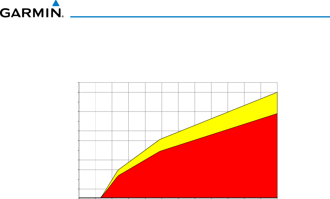
190-00928-04 Rev. A
Garmin G1000 Pilot’s Guide for the Beechcraft 200/B200 Series
409
HAZARD AVOIDANCE
EXCESSIVE DESCENT RATE ALERT
The purpose of the Excessive Descent Rate (EDR) alert is to provide suitable notification when the
aircraft is determined to be closing (descending) upon terrain at an excessive speed. Figure 6-127 shows the
parameters for the alert as defined by TSO-C151b.
0
500
1000
1500
2000
2500
3000
3500
4000
4500
5000
5500
6000
0
1000
2000
3000
4000
5000
6000
7000
8000
9000
10000
11000
12000
Descent Rate (FPM)
Height Above Terrain (Feet)
Caution: “SINK RATE”
Warning: “PULL-UP”
Figure 6-127 Excessive Descent Rate Alert Criteria
FORWARD LOOKING TERRAIN AVOIDANCE
The Forward Looking Terrain Avoidance (FLTA) feature of TAWS-B compares the aircraft’s projected flight
path with known terrain and obstacles in their respective databases and issues four types of alerts as either a
caution or a warning:
Reduced Required Terrain Clearance (RTC) and Reduced Required Obstacle Clearance (ROC)
alerts are issued when the aircraft flight path is above terrain, yet is projected to come within the minimum
clearance values in Figure 6-128. When an RTC alert is issued, the system displays a potential impact point
on navigation maps and the TAWS-B Page.
Imminent Terrain Impact (ITI) and Imminent Obstacle Impact (IOI) alerts are issued when the
aircraft is below the elevation of a terrain or obstacle cell in the aircraft’s projected path. ITI and IOI alerts
are accompanied by a potential impact point on the navigation maps and the TAWS-B Page. The alert is
annunciated when the projected vertical flight path is calculated to come within minimum clearance altitudes
in Figure 6-128.
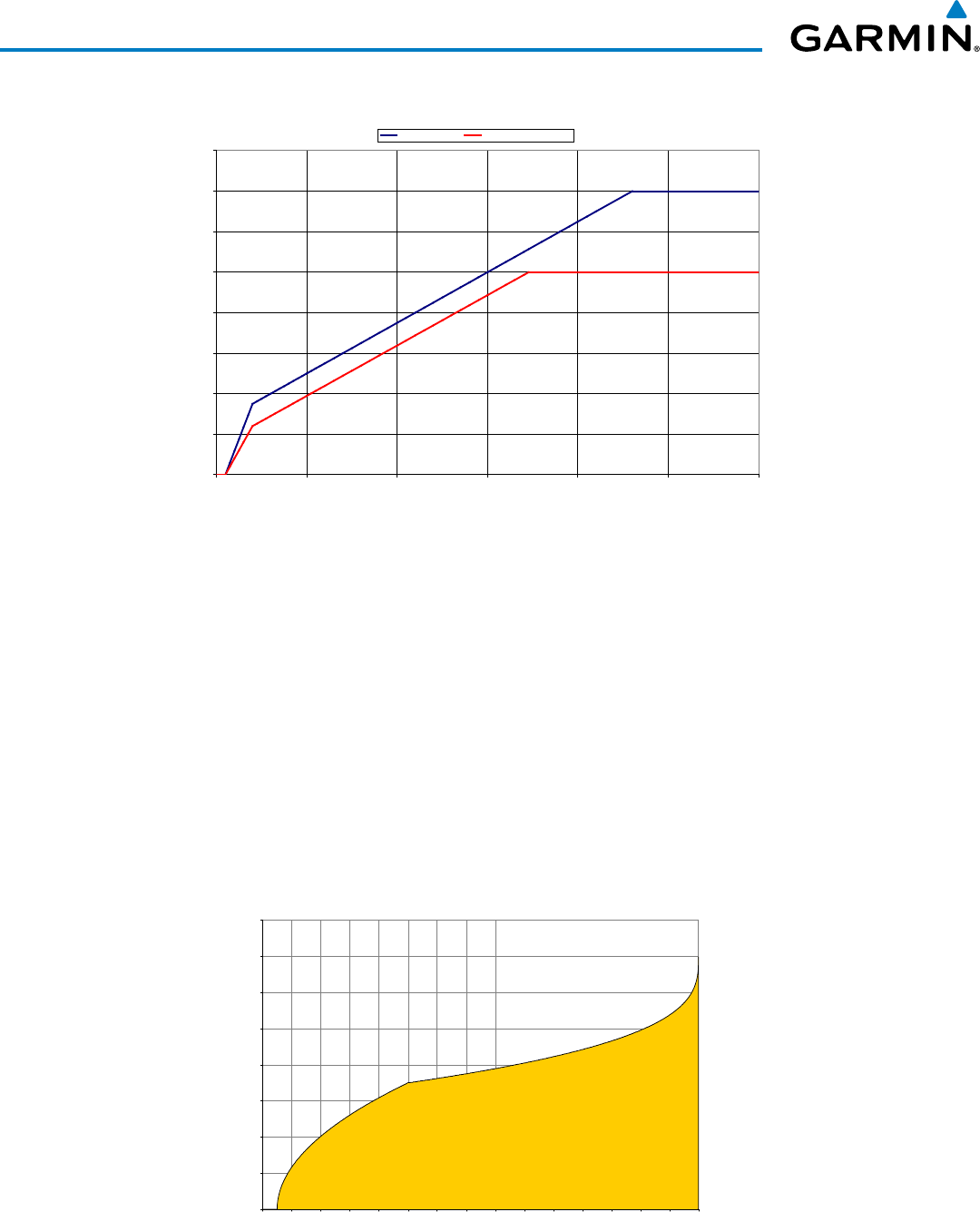
Garmin G1000 Pilot’s Guide for the Beechcraft 200/B200 Series
190-00928-04 Rev. A410
HAZARD AVOIDANCE
Required Terrain Clearance
0
100
200
300
400
500
600
700
800
0 5 10 15 20 25 30
Distance From Runway (NM)
Required Terrain Clearance (FT)
RTC Level (FT) RTC Descending (FT)
Figure 6-128 FLTA Alert Minimum Terrain and Obstacle Clearance Values
Distance From Runway (NM)
Required Terrain Clearance (FT)
The system automatically suppresses FLTA alerts from occurring under any of the following conditions:
• The aircraft is less than 200 feet above the destination elevation and within 0.5 nm of the destination.
• The aircraft is less than fifty feet above terrain or on the ground.
• The aircraft is between runway ends.
PREMATURE DESCENT ALERTING
A Premature Descent Alert (PDA) is issued when the system detects that the aircraft is significantly
below the normal approach path to a runway (Figure 6-129).
PDA alerting begins when the aircraft is below 700 feet AGL within 15 nm of the destination airport and
ends when the aircraft is 0.5 nm from the runway threshold.
Figure 6-129 PDA Alerting Threshold
0
100
200
300
400
500
600
700
800
0
1
2
3
4
5
6
7
8
9
10
11
12
13
14
15
Height Above Destination (Feet)
Distance to Destination (NM)
PDA ALERTING AREA

190-00928-04 Rev. A
Garmin G1000 Pilot’s Guide for the Beechcraft 200/B200 Series
411
HAZARD AVOIDANCE
PDA and FLTA visual annunciations and voice alerts can be manually inhibited. Discretion should be used
when inhibiting TAWS-B and the system should be enabled when appropriate. When TAWS-B is inhibited,
the alert annunciation ‘TAWS INH’ is shown on the PFD and MFD (Figure 6-130).
Figure 6-130 TAWS-B Alerting Disabled
(TAWS-B Inhibited) Annunciation
Inhibiting/enabling TAWS-B alerting:
1) Select the TAWS-B Page.
2) Select the INHIBIT Softkey to inhibit or enable TAWS-B (choice dependent on current state).
Or:
a) Press the MENU Key.
b) Select ‘Inhibit TAWS’ or ‘Enable TAWS’ (choice dependent on current state) and press the ENT Key.
While TAWS-B alerting is inhibited, is unavailable, or has failed, the system may show a ‘LOW ALT’
annunciation on the PFDs if all of these conditions are met:
• The aircraft is on a GPS SBAS approach.
• The Final Approach Fix (FAF) is the active waypoint.
• The aircraft altitude is at least 164 feet below the prescribed FAF altitude.
Refer to the Flight Instruments for more information about the ‘LOW ALT’ annunciation.
ALTITUDE VOICE CALLOUT (VCO) ALERT
The system provides a “Five-hundred” voice alert when the aircraft descends to within 500 feet above the
terrain or runway threshold. When the aircraft is within 5 nm of an airport, the “Five Hundred” voice alert is
based on the nearest runway threshold elevation. When the aircraft is more than 5 nm of the nearest airport,
the “Five Hundred” voice alert is based on the height above terrain, by comparing the aircraft’s GPS-GSL
altitude to the terrain database.
There are no display annunciations or pop-up alerts that accompany the VCO alert. This alert cannot be
inhibited.
NEGATIVE CLIMB RATE AFTER TAKEOFF ALERT (NCR)
The Negative Climb Rate (NCR) After Takeoff alert (also referred to as “Altitude Loss After Takeoff”)
provides alerts when the system determines the aircraft is losing altitude (closing upon terrain) after takeoff.
The voice alert “Don’t Sink” is given for NCR alerts, accompanied by visual annunciations. NCR alerting is
only active when departing from an airport and when the following conditions are met:
• Height above the terrain is less than 700 feet
• Distance from the departure airport is 5 nm or less
• Heading change from the departure heading is less than 110 degrees
NCR alerts can be triggered by either altitude loss (Figure 6-131) or sink rate (6-132).
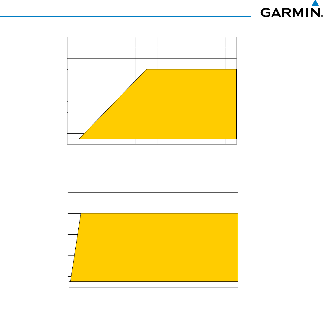
Garmin G1000 Pilot’s Guide for the Beechcraft 200/B200 Series
190-00928-04 Rev. A412
HAZARD AVOIDANCE
Figure 6-131 Negative Climb Rate (NCR) Altitude Loss
0
100
200
300
400
500
600
700
800
900
1000
0 20 40 60 80 100 120 140
Altitude Loss (Feet)
Height Above Terrain (Feet)
“DON’T SINK”
or
“TOO LOW, TERRAIN”
Figure 6-132 Negative Climb Rate (NCR) Sink Rate
0
100
200
300
400
500
600
700
800
900
1000
0 500 1000 1500 2000 2500 3000 3500 4000 4500 5000 5500 6000 6500 7000
Sink Rate (FPM)
Height Above Terrain (Feet)
“DON’T SINK”
or
“TOO LOW, TERRAIN”
SYSTEM STATUS
During power-up, TAWS-B conducts a system test of its alerting capabilities. The system test can also be
manually initiated. The system issues a voice alert when the test has concluded. TAWS-B System Testing is
disabled when ground speed exceeds 30 knots.
Manually testing the TAWS-B System:
1) Select the TAWS-B Page.
2) Press the MENU Key.
3) Select ‘Test TAWS System’ and press the ENT Key to confirm the selection. (Figure 6-133)
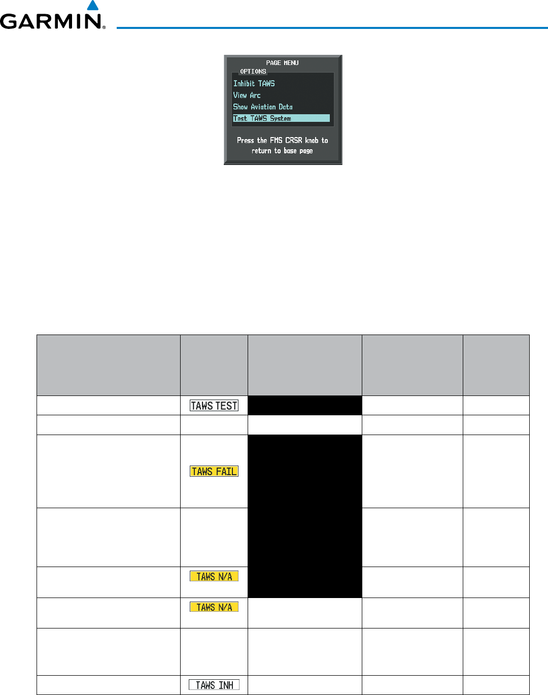
190-00928-04 Rev. A
Garmin G1000 Pilot’s Guide for the Beechcraft 200/B200 Series
413
HAZARD AVOIDANCE
Figure 6-133 TAWS-B Page Menu
TAWS-B continually monitors several system-critical items such as database validity, hardware status, and
GPS status. If the terrain/obstacle database is not available, the voice alert “TAWS System Failure” is generated
along with the ‘TAWS FAIL’ visual annunciation.
TAWS-B requires a 3-D GPS navigation solution along with specific vertical accuracy minimums. Should the
navigation solution become degraded or if the aircraft is out of the database coverage area, the annunciation
‘TAWS N/A’ is generated in the annunciation window and on the TAWS-B Page. If in-flight, the voice alert
“TAWS Not Available” is also generated. When the GPS signal is restored and the aircraft is within the
database coverage area, the voice alert “TAWS Available” is generated.
Alert Type
PFD/MFD
TAWS-B Page
Annunciation
TAWS-B Page Center
Banner Annunciation
Voice Alert
TAWS Alert
Types
Not
Available
System Test in progress TAWS TEST None None Available
System Test pass None None “TAWS System Test OK”
TAWS System Test Fail; Terrain,
Airport Terrain or Obstacle
database unavailable or invalid
on all GDUs; software mismatch
among GDUs; TAWS audio fault
TAWS FAIL “TAWS System Failure” FLTA, PDA
MFD Terrain or Obstacle database
unavailable or invalid. TAWS
operating with PFD Terrain or
Obstacle databases
None TERRAIN DATABASE
FAILURE None
No GPS position NO GPS POSITION “TAWS Not Available” FLTA, PDA,
VCO
Excessively degraded GPS signal, or
out of database coverage area
None “TAWS Not Available” FLTA, PDA
Sufficient GPS signal reception
restored
None
None “TAWS Available”
(voice alert only in
flight)
TAWS Alerting is disabled None None FLTA, PDA
Table 6-15 TAWS-B System Status Annunciations
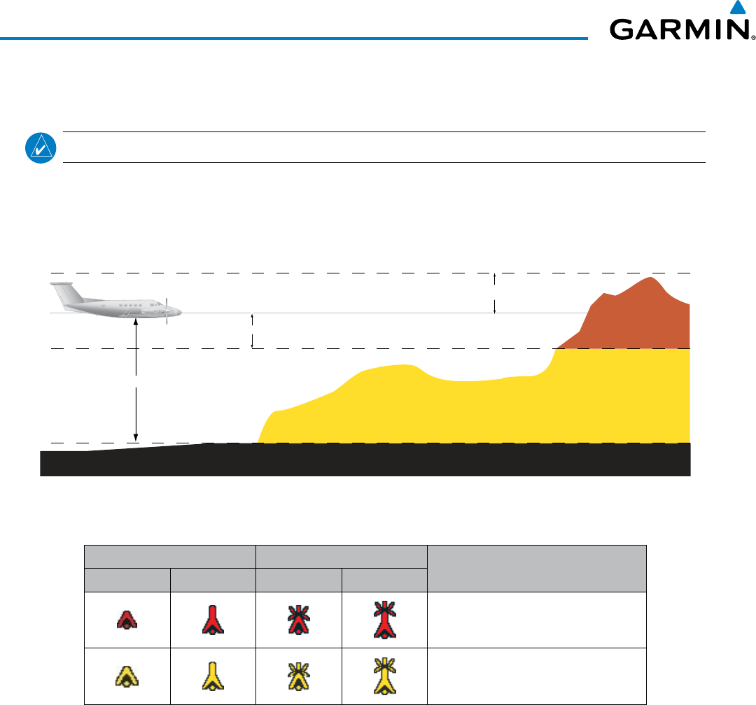
Garmin G1000 Pilot’s Guide for the Beechcraft 200/B200 Series
190-00928-04 Rev. A414
HAZARD AVOIDANCE
6.6 PROFILE VIEW TERRAIN
NOTE: Profile View is not available in TAWS-A installations.
The G1000 offers a Profile View of terrain and obstacles relative to the aircraft’s current flight path and altitude
on the Navigation Map Page of the MFD. The Profile View feature is not part of the TAWS system discussed
previously, and it does not provide alerting capabilities. The colors and symbols in Figure 6-134 and Table 6-16
are used to represent terrain and obstacles inside the Profile View Window.
1000 ft
Aircraft Altitude
100 ft Threshold
Terrain Above Aircraft Altitude
Red terrain is above
or within 100 ft below
the aircraft altitude
Yellow terrain is between 100 ft and 1000 ft below the aircraft altitude
Black terrain is more than 1000 ft below the aircraft altitude
Figure 6-134 Terrain Altitude/Color Correlation for Profile View Terrain
Unlighted Obstacle Lighted Obstacle Obstacle Location
< 1000’ AGL > 1000’ AGL < 1000’ AGL > 1000’ AGL
Red obstacle is above or within 100 ft
below the aircraft altitude
Yellow obstacle is between 100 ft and
1000 ft below the aircraft altitude
Table 6-16 Profile View Terrain/Obstacle Colors and Symbology
Enabling/Disabling Profile View:
1) Select the Navigation Map Page.
2) Select the MAP Softkey.
3) Select the PROFILE Softkey to enable or disable Profile View.
Or:
a) Press the MENU Key.
b) Select ‘Show Profile View’ or ‘Hide Profile View’ (choice dependent on current state) and press the ENT Key.

190-00928-04 Rev. A
Garmin G1000 Pilot’s Guide for the Beechcraft 200/B200 Series
415
HAZARD AVOIDANCE
Enabling/Disabling Profile View Terrain on the Navigation Map (when Profile View is enabled):
1) Select the Navigation Map Page.
2) Select the MAP Softkey.
3) Select the TERRAIN Softkey.
PROFILE VIEW DISPLAY
When the Profile View is enabled, it is displayed in a window below the Navigation Map. Altitude is shown
along a vertical scale, with an aircraft icon positioned at the current altitude. Distance is represented horizontally
along the bottom of the Profile View Window, and increases from left (present position) to right.
When the Navigation Map range is adjusted with the RANGE Knob, the horizontal distance of the Profile
View is adjusted proportionately to be 1/2 of the Navigation Map range distance down to 1 nm, at which point
Profile View is no longer available (‘PROFILE NOT AVAILABLE’ is displayed). When Navigation Map range is
adjusted to remove altitude-correlated colored terrain data (as shown in the Terrain Legend) or obstacles from
the Navigation Map, these items are also removed from the Profile View; only an outline of the terrain will be
displayed in black in the Profile View window. Refer to the or TAWS-B discussion for more information about
displaying terrain or obstacles on the Navigation Map Page.
Terrain Legend
Profile View Length
is One Half of the
Navigation Map
Range
Figure 6-135 Profile View on Navigation Map with Terrain Display Enabled
Altitude Scale
Distance Scale
Terrain Enabled Icons
Navigation Map Range
Profile Path
Range
Markers
The Profile View is based on the current aircraft track (or heading if track is unavailable) and shows the highest
known terrain or obstacles within a predetermined width from the present aircraft position to the end of the
profile range. The width of the Profile View is determined by the phase of flight, as annunciated on the HSI,
and is widest during enroute or oceanic phases (Table 6-17).

Garmin G1000 Pilot’s Guide for the Beechcraft 200/B200 Series
190-00928-04 Rev. A416
HAZARD AVOIDANCE
Flight Phase Total Profile View Width
Approach 0.6 nm
Departure 0.6 nm
Terminal 2.0 nm
Enroute 4.0 nm
Oceanic 4.0 nm
Table 6-17 Profile View Width Scale
PROFILE PATH
The Profile Path displays the horizontal and lateral boundaries of the Profile View. The path is shown as a
white rectangle on the Navigation Map Page and is only available when Profile View is enabled. White range
markers both edges of the Profile Path rectangle match the range markers along the distance scale inside the
Profile View display window whenever the profile range is at least 4 nm (or 7.5 km if configured for metric
units).
The Profile Path rectangle may be enabled/disabled, and the Navigation Map range at which the Profile Path
is removed from map display can be changed.
Customizing the Profile Path display on the Navigation Map Page:
1) Select the Navigation Map Page.
2) Press the MENU Key.
3) With ‘Map Setup’ highlighted, press the
ENT
Key (Figure 6-136).
4) Turn the small FMS Knob to select the ‘Profile’ Group and press the ENT Key (Figure 6-137).
5) Turn the large
FMS
Knob or press the
ENT
Key to scroll through product selections (Figure 6-138).
• PROFILE PATH – Turns the display of the Profile Path on or off and sets maximum range at which Profile Path
is shown
6) Turn the small
FMS
Knob to scroll through options (ON/OFF, range settings).
7) Press the
ENT
Key to select an option.
8) Press the FMS Knob or CLR Key to return to the Navigation Map Page with the changed settings.
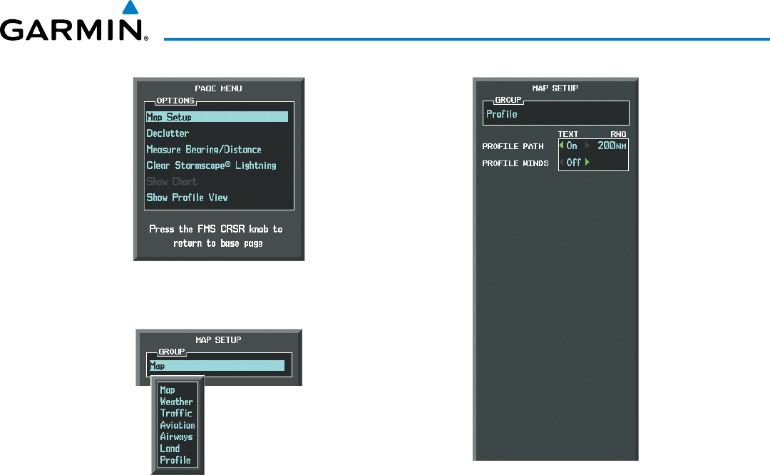
190-00928-04 Rev. A
Garmin G1000 Pilot’s Guide for the Beechcraft 200/B200 Series
417
HAZARD AVOIDANCE
Figure 6-137 Navigation Map Page Setup Menu
Figure 6-136 Navigation Map Page Menu
Figure 6-138 Navigation Map Page Setup Menu,
Profile Group
Garmin G1000 Pilot’s Guide for the Beechcraft 200/B200 Series
190-00928-04 Rev. A418
HAZARD AVOIDANCE
6.7 TAWS-A
WARNING: Do not use TAWS information for primary terrain avoidance. TAWS-A is intended only to enhance
situational awareness.
NOTE: Terrain data is not displayed when the aircraft is outside of the installed terrain database coverage
area.
NOTE: The data contained in the TAWS databases comes from government agencies. Garmin accurately
processes and cross-validates the data but cannot guarantee the accuracy and completeness of the data.
TAWS-A (Terrain Awareness and Warning System - Class A) is an optional feature to increase situational
awareness and aid in reducing controlled flight into terrain (CFIT). TAWS-A provides visual annunciations and
voice alerts when terrain and obstacles are within the given altitude threshold from the aircraft. The displayed
alerts and warnings are advisory in nature only.
TAWS-A satisfies TSO-C151b Class A and TSO-92c requirements for certification.
Class A TAWS requires the following components:
• A valid terrain/obstacle/airport terrain database
• A valid 3-D GPS position solution
• Valid flap and landing gear status inputs
• A valid radar altimeter
TAWS-A uses terrain and obstacle information supplied by government sources. Terrain information is based
on terrain elevation information in a database that may contain inaccuracies. Individual obstructions may be
shown if available in the database. Garmin verifies the data to confirm accuracy of the content, per TSO-C151b.
However, the displayed information should never be understood as being all-inclusive and the data may still
contain inaccuracies.
TAWS-A uses information from the GPS receiver to provide a horizontal position and altitude, along with
additional altitude input from the radar altimeter. GPS altitude is derived from satellite measurements. The
system converts GPS altitude to a height above geodetic sea level (GSL), which is the height above mean seal level
(MSL) calculated geometrically. GSL altitude accuracy is affected by factors such as satellite geometry, but it is not
subject to variations in pressure and temperature that normally affect pressure altitude devices. GSL altitude does
not require local altimeter settings to determine MSL altitude. Therefore, GSL altitude provides a highly accurate
and reliable MSL altitude source to calculate terrain and obstacle alerts.
The terrain and obstacle databases used by TAWS-A are referenced to mean sea level (MSL). Using the GPS
position and GSL altitude, TAWS-A displays a 2-D picture of the surrounding terrain and obstacles relative to the
position and altitude of the aircraft. Furthermore, the GPS position and GSL altitude are used to calculate and
“predict” the aircraft’s flight path in relation to the surrounding terrain and obstacles. In this manner, TAWS-A
can provide advanced alerts of predicted dangerous terrain conditions.
TAWS-A incorporates radar altimeter input with the GSL altitude to provide a more accurate position reference
when at lower altitudes for certain alert types, and to retain a level of ground proximity warning capability in the
unlikely event of a terrain or obstacle database failure.
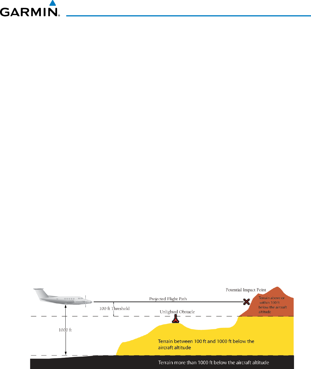
190-00928-04 Rev. A
Garmin G1000 Pilot’s Guide for the Beechcraft 200/B200 Series
419
HAZARD AVOIDANCE
Baro-corrected altitude (or indicated altitude) is derived by adjusting the altimeter setting for local atmospheric
conditions. The most accurate baro-corrected altitude can be achieved by frequently updating the altimeter
setting to the nearest reporting station along the flight path. However, because actual atmospheric conditions
seldom match the standard conditions defined by the International Standard Atmosphere (ISA) model (where
pressure, temperature, and lapse rates have fixed values), it is common for the baro-corrected altitude (as read
from the altimeter) to differ from the GPS-MSL altitude. This variation results in the aircraft’s true altitude
differing from the baro-corrected altitude.
TAWS-A provides the following alert types:
• Forward Looking Terrain Avoidance (FLTA) Alerting, which consists of:
• Required Terrain Clearance (RTC) / Required Obstacle Clearance (ROC) Alerting
• Imminent Terrain Impact (ITI) / Imminent Obstacle Impact (IOI) Alerting
• Premature Descent Alerting (PDA)
• Ground Proximity Warning System (GPWS) Alerting, which consists of:
• Excessive Descent Rate (EDR) Alerting
• Excessive Closure Rate (ECR) to Terrain Alerting
• Flight Into Terrain (FIT) Alerting
• Negative Climb Rate (NCR) after takeoff Alerting
• Excessive below Glideslope/Glidepath Deviation (GSD) Alerting
• Altitude Voice Call Out (VCO) Alerting
DISPLAYING TAWS-A DATA
TAWS-A uses yellow (caution) and red (warning) to depict terrain and obstacles (with heights greater than
200 feet above ground level, AGL) alerts relative to aircraft altitude. Colors are adjusted automatically as
the aircraft altitude changes. The colors and symbols in Figure 6-139 and Tables 6-18 and 6-19 are used to
represent terrain, obstacles, and potential impact points.
Figure 6-139 Terrain Altitude/Color Correlation for TAWS-A
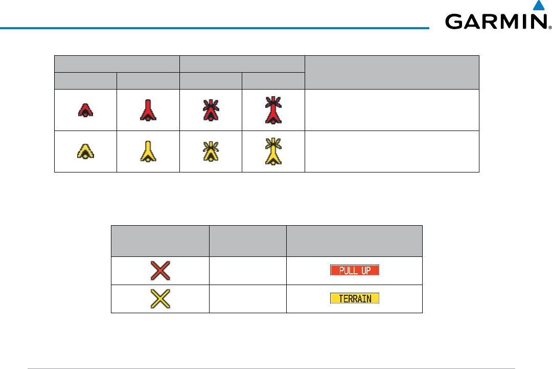
Garmin G1000 Pilot’s Guide for the Beechcraft 200/B200 Series
190-00928-04 Rev. A420
HAZARD AVOIDANCE
Unlighted Obstacle Lighted Obstacle Obstacle Location
< 1000’ AGL > 1000’ AGL < 1000’ AGL > 1000’ AGL
Red obstacle is above or within 100 ft
below the aircraft altitude
Yellow obstacle is between 100 ft and
1000 ft below the aircraft altitude
Table 6-18 TAWS-A Obstacle Colors and Symbology
Potential Impact
Point Symbol Alert Type Example Annunciation
Warning
Caution
Table 6-19 TAWS-A Potential Impact Point Symbols with Alert Types
TAWS-A PAGE
The TAWS-A Page shows terrain, obstacle, and potential impact point data in relation to the aircraft’s current
altitude, without clutter from the basemap. Aviation data (airports, VORs, and other NAVAIDs) can be displayed
for reference. If an obstacle and the projected flight path of the aircraft intersect, the system reduces the
TAWS-A Page map range if necessary to clearly show the potential impact point.
Aircraft orientation on this map is always heading up unless there is no valid heading. Two views are available
relative to the position of the aircraft: the 360° default display and the radar-like ARC (120°) display. Map range
is adjustable with the RANGE Knob from 1 to 200 nm, as indicated by the map range rings (or arcs).
Displaying the TAWS-A Page:
1) Turn the large
FMS
Knob to select the Map Page Group.
2) Turn the small
FMS
Knob
to select the TAWS-A Page.
Changing the TAWS-A Page view:
1) Select the
VIEW
Softkey.
2) Select the 360 or ARC Softkey to select the desired view.
Or:
1) Press the MENU Key.
2)
Select ‘View Arc’ or ‘View 360º’ (choice dependent on current state) and press the ENT Key to change the view
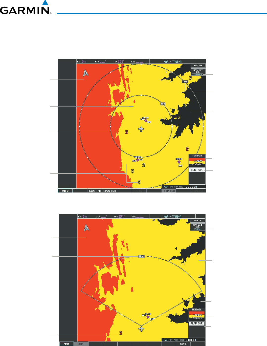
190-00928-04 Rev. A
Garmin G1000 Pilot’s Guide for the Beechcraft 200/B200 Series
421
HAZARD AVOIDANCE
Showing/hiding aviation information on the TAWS-A Page:
1) Press the MENU Key.
2) Select ‘Show Aviation Data’ or ‘Hide Aviation Data’ (choice dependent on current state) and press the ENT Key.
Figure 6-140 TAWS-A Page, 360º View
Yellow Terrain
(Caution - Terrain
Between 100’ and
1000’ Below the
Aircraft Altitude)
Red Terrain
(Warning - Terrain
Above or Within
100’ Below the
Aircraft Altitude)
Terrain Legend
Map Range
Black Terrain
(Terrain More than
1000’ Below the
Aircraft Altitude)
Annunciation Window
Red Lighted
Obstacle is Above
or Within 100’
Below Aircraft
Altitude
Yellow Lighted
Obstacles are
Between 100’
and 1000’ Below
Aircraft Altitude
Current
Aircraft GPS-
derived GSL
Altitude
Figure 6-141 TAWS-A Page (ARC View)
Terrain Legend
Annunciation Window
Arc Range
Red Terrain
(Warning - Terrain
Above or Within
100’ Below the
Aircraft Altitude)
Current
Aircraft GPS-
derived GSL
Altitude
Red Lighted
Obstacle is Above
or Within 100’
Below Aircraft
Altitude
Yellow Terrain
(Caution - Terrain
Between 100’ and
1000’ Below the
Aircraft Altitude)
Black Terrain
(Terrain More than
1000’ Below the
Aircraft Altitude)
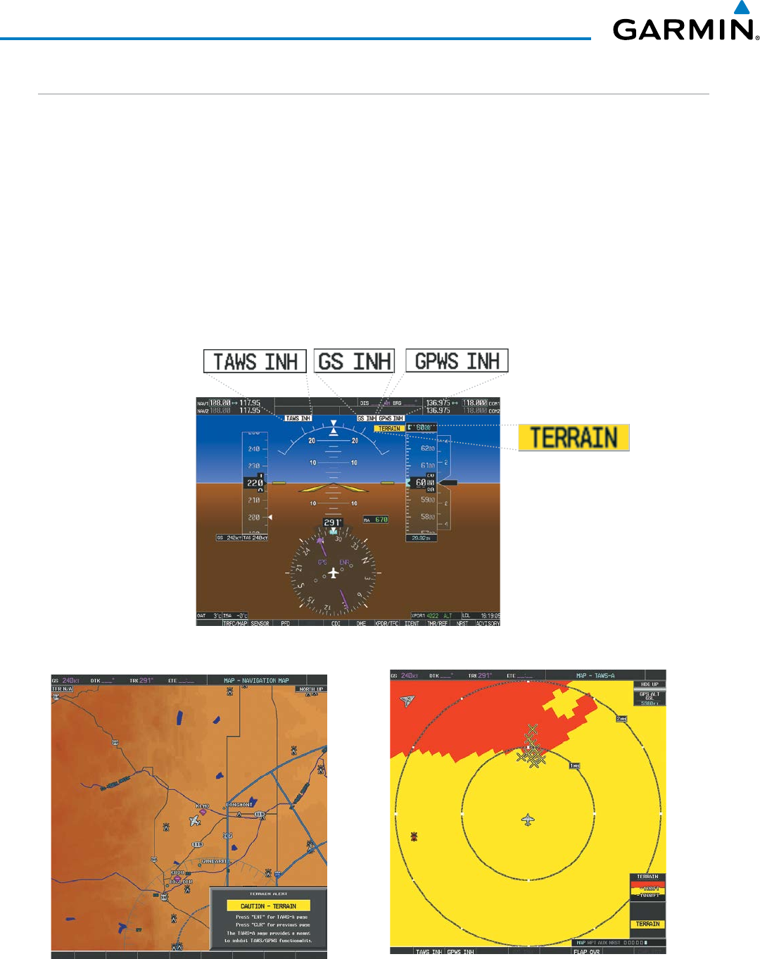
Garmin G1000 Pilot’s Guide for the Beechcraft 200/B200 Series
190-00928-04 Rev. A422
HAZARD AVOIDANCE
TAWS-A ALERTS
Alerts are issued when flight conditions meet parameters that are set within TAWS-A software algorithms.
TAWS-A alerts typically employ a CAUTION or a WARNING alert severity level, or both. When an alert is
issued, the system displays visual annunciations with voice alerts. Table 6-20 shows TAWS-A alert types with
corresponding annunciations and voice alerts.
When an alert is issued, annunciations appear on the PFD and MFD. The TAWS-A Alert Annunciation is
shown to the upper left of the Altimeter or upper right of the Airspeed indicator on the PFD and below the
Terrain Legend on the MFD. If the TAWS-A Page is not already displayed on the MFD, a pop-up alert appears
on the MFD while an alert is active. When a pop-up alert occurs, do one of the following:
• Press the CLR Key (removes the pop-up alert), or
• Press the ENT Key (accesses the TAWS-A Page)
Figure 6-142 Example TAWS-A Annunciations
MFD Pop-Up Alert (on non-TAWS-A pages) MFD TAWS-A Page with Alert Annunciation
PFD with TAWS-A Annunciations
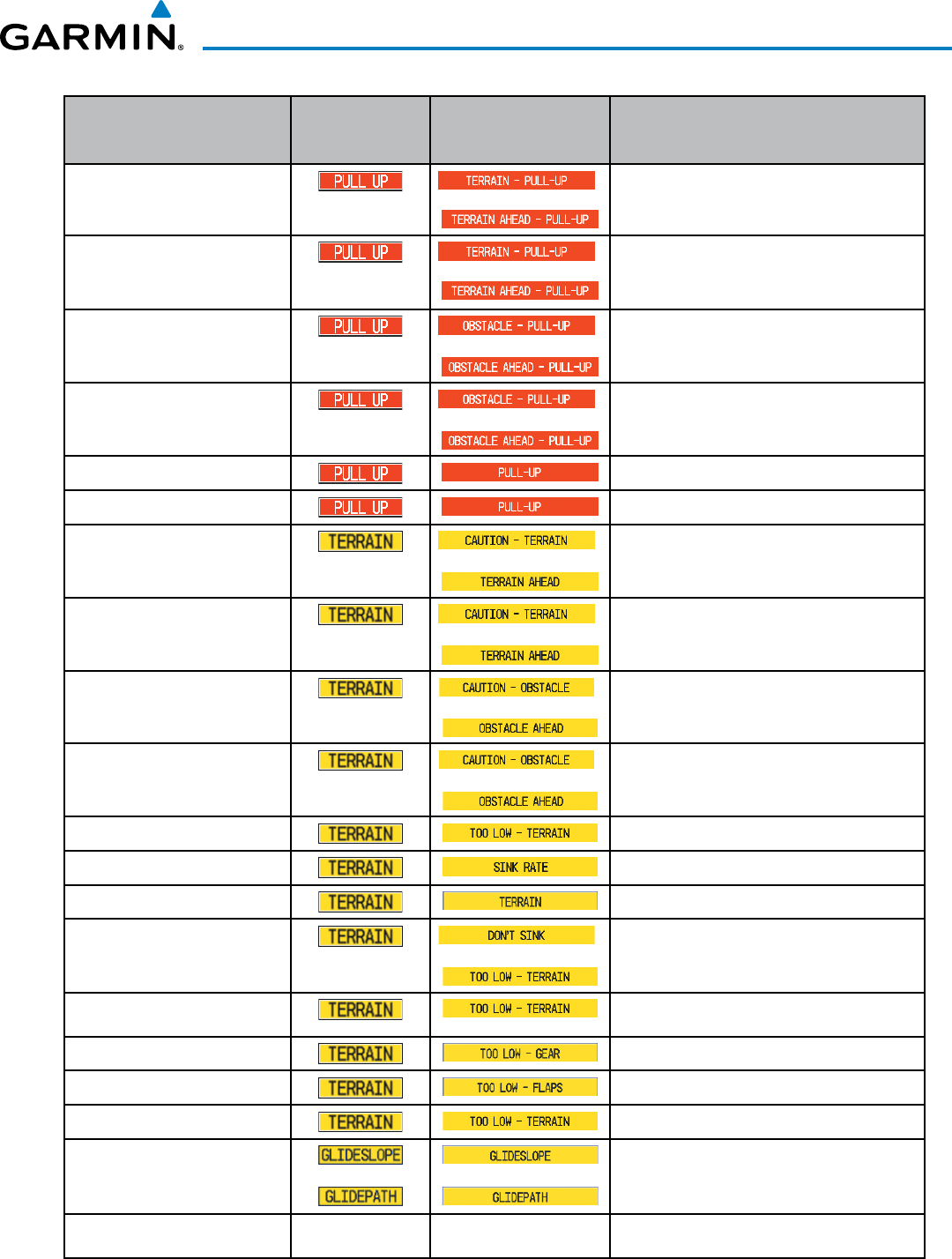
190-00928-04 Rev. A
Garmin G1000 Pilot’s Guide for the Beechcraft 200/B200 Series
423
HAZARD AVOIDANCE
Alert Type PFD/MFD TAWS-A
Page
Annunciation
MFD Map Page
Pop-Up Alert
(Except TAWS-A Page) Voice Alert
Reduced Required Terrain Clearance
Warning (RTC) *
or
“Terrain, Terrain; Pull-Up, Pull-Up” *
or
“Terrain Ahead, Pull-Up; Terrain Ahead, Pull-Up”
Imminent Terrain Impact Warning (ITI) *
or
“Terrain, Terrain; Pull-Up, Pull-Up”*
or
Terrain Ahead, Pull-Up; Terrain Ahead, Pull-Up”
Reduced Required Obstacle Clearance
Warning (ROC)*
or
“Obstacle, Obstacle; Pull-Up, Pull-Up”*
or
“Obstacle Ahead, Pull-Up; Obstacle Ahead, Pull-Up”
Imminent Obstacle Impact Warning (IOI) *
or
“Obstacle, Obstacle; Pull-Up, Pull-Up”*
or
“Obstacle Ahead, Pull-Up; Obstacle Ahead, Pull-Up”
Excessive Descent Rate Warning (EDR) “<whoop> <whoop> Pull-Up”
Excessive Closure Rate Warning (ECR) “<whoop> <whoop> Pull-Up”
Reduced Required Terrain Clearance
Caution (RTC) *
or
“Caution, Terrain; Caution, Terrain”*
or
“Terrain Ahead; Terrain Ahead”
Imminent Terrain Impact Caution (ITI) *
or
“Caution, Terrain; Caution, Terrain”
or
“Terrain Ahead; Terrain Ahead”
Reduced Required Obstacle Clearance
Caution (ROC) *
or
“Caution, Obstacle; Caution, Obstacle”*
or
“Obstacle Ahead; Obstacle Ahead”
Imminent Obstacle Impact Caution (IOI) *
or
“Caution, Obstacle; Caution, Obstacle”*
or
“Obstacle Ahead; Obstacle Ahead”
Premature Descent Alert Caution (PDA) “Too Low, Terrain”
Excessive Descent Rate Caution (EDR) “Sink Rate”
Excessive Closure Rate Caution (ECR) “Terrain, Terrain”
Negative Climb Rate Caution (NCR) *
or
“Don’t Sink”*
or
“Too Low, Terrain”
Flight Into Terrain High Speed Caution
(FIT) “Too Low, Terrain”
Flight Into Terrain Gear Caution (FIT) “Too Low, Gear”
Flight Into Terrain Flaps Caution (FIT) “Too Low, Flaps”
Flight Into Terrain Takeoff Caution (FIT) “Too Low, Terrain”
Glide Slope Deviation Caution (GSD)
(depends on approach type) or or
“Glideslope”
or
“Glidepath”
Altitude Voice Callout (VCO) None None “Five Hundred”, “Four Hundred”*, “Three Hundred”*,
“Two Hundred”*, “One Hundred”*
* Alerts with multiple messages are configurable. Alerts for the default configuration are indicated with asterisks.
Table 6-20 TAWS-A Alerts Summary
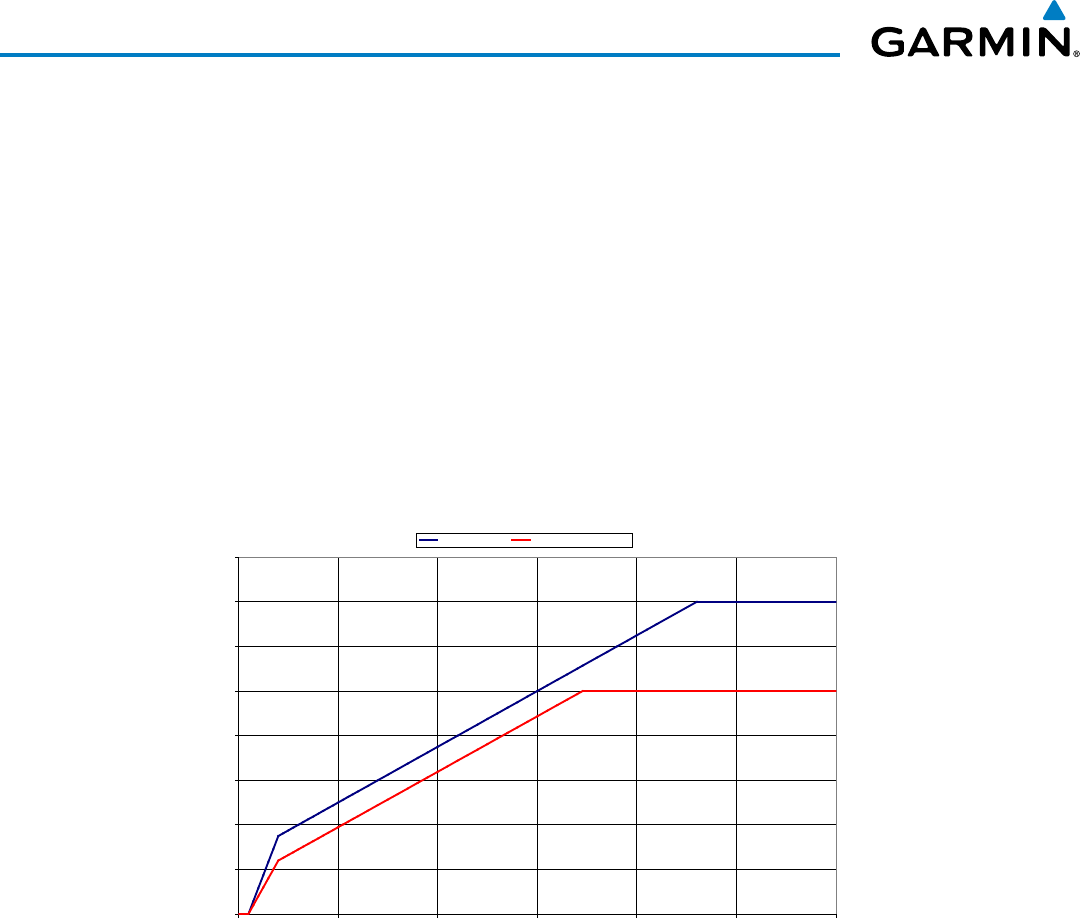
Garmin G1000 Pilot’s Guide for the Beechcraft 200/B200 Series
190-00928-04 Rev. A424
HAZARD AVOIDANCE
FORWARD LOOKING TERRAIN AVOIDANCE (FLTA)
The Forward Looking Terrain Avoidance (FLTA) feature of TAWS-A compares the aircraft’s projected flight
path with known terrain and obstacles in their respective databases and issues four types of alerts as either a
caution or a warning:
Reduced Required Terrain Clearance (RTC) and Reduced Required Obstacle Clearance (ROC)
alerts are issued when the aircraft flight path is above terrain, yet is projected to come within the minimum
clearance values in Figure 6-143. When an RTC alert is issued, a potential impact point is displayed on the
TAWS-A Page.
Imminent Terrain Impact (ITI) and Imminent Obstacle Impact (IOI) alerts are issued when the
aircraft is below the elevation of a terrain or obstacle cell in the aircraft’s projected path. ITI and IOI alerts
are accompanied by a potential impact point displayed on the TAWS-A Page. The alert is annunciated when
the projected vertical flight path is calculated to come within minimum clearance altitudes in Figure 6-143.
Required Terrain Clearance
0
100
200
300
400
500
600
700
800
0 5 10 15 20 25 30
Distance From Runway (NM)
Required Terrain Clearance (FT)
RTC Level (FT) RTC Descending (FT)
Figure 6-143 FLTA Alert Minimum Terrain and Obstacle Clearance Values
Distance From Runway (NM)
Required Terrain Clearance (FT)
The system automatically suppresses FLTA alerts from occurring under any of the following conditions:
• The aircraft is less than 200 feet above the destination elevation and within 0.5 nm of the destination.
• The aircraft is less than fifty feet above terrain or on the ground.
• The aircraft is between runway ends.
PREMATURE DESCENT ALERTING
A Premature Descent Alert (PDA) is issued when the system detects that the aircraft is significantly
below the normal approach path to a runway (Figure 6-144).
PDA alerting begins when the aircraft is below 700 feet AGL within 15 nm of the destination airport and
ends when the aircraft is 0.5 nm from the runway threshold.
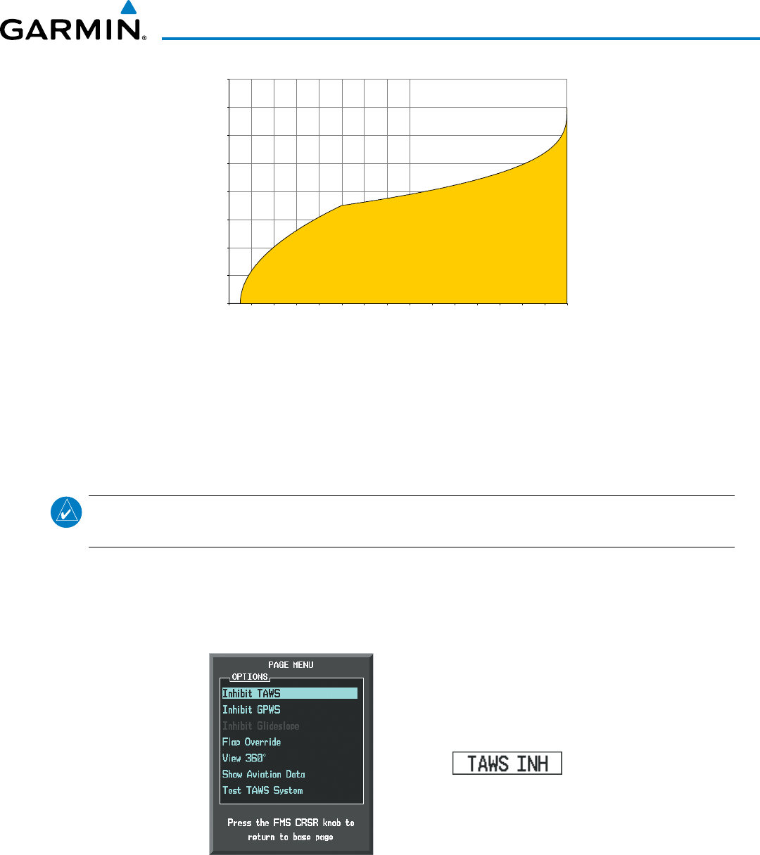
190-00928-04 Rev. A
Garmin G1000 Pilot’s Guide for the Beechcraft 200/B200 Series
425
HAZARD AVOIDANCE
Figure 6-144 PDA Alerting Threshold
0
100
200
300
400
500
600
700
800
0
1
2
3
4
5
6
7
8
9
10
11
12
13
14
15
Height Above Destination (Feet)
Distance to Destination (NM)
PDA ALERTING AREA
PDA alerting begins when the aircraft is below 700 feet AGL within 15 nm of the destination airport and
ends when the aircraft is 0.5 nm from the runway threshold.
inHiBiting Flta anD PDa aleRtS
NOTE: The ‘Inhibit TAWS’ function only inhibits FLTA and PDA alerts. Alerting for GPWS alerts (EDR, ECR,
NCR, FIT) and GSD is controlled independently from FLTA and PDA alerts.
FLTA and PDA visual annunciations and voice alerts can be manually inhibited. Discretion should be used
when inhibiting alerts and the system should be enabled when appropriate. When PDA and FLTA alerts are
inhibited, the alert annunciation ‘TAWS INH’ is shown on the PFD and on the TAWS-A Page annunciation
window of the MFD (Figure 6-145).
Figure 6-145 TAWS-A Page Menu and Inhibit Annunciation
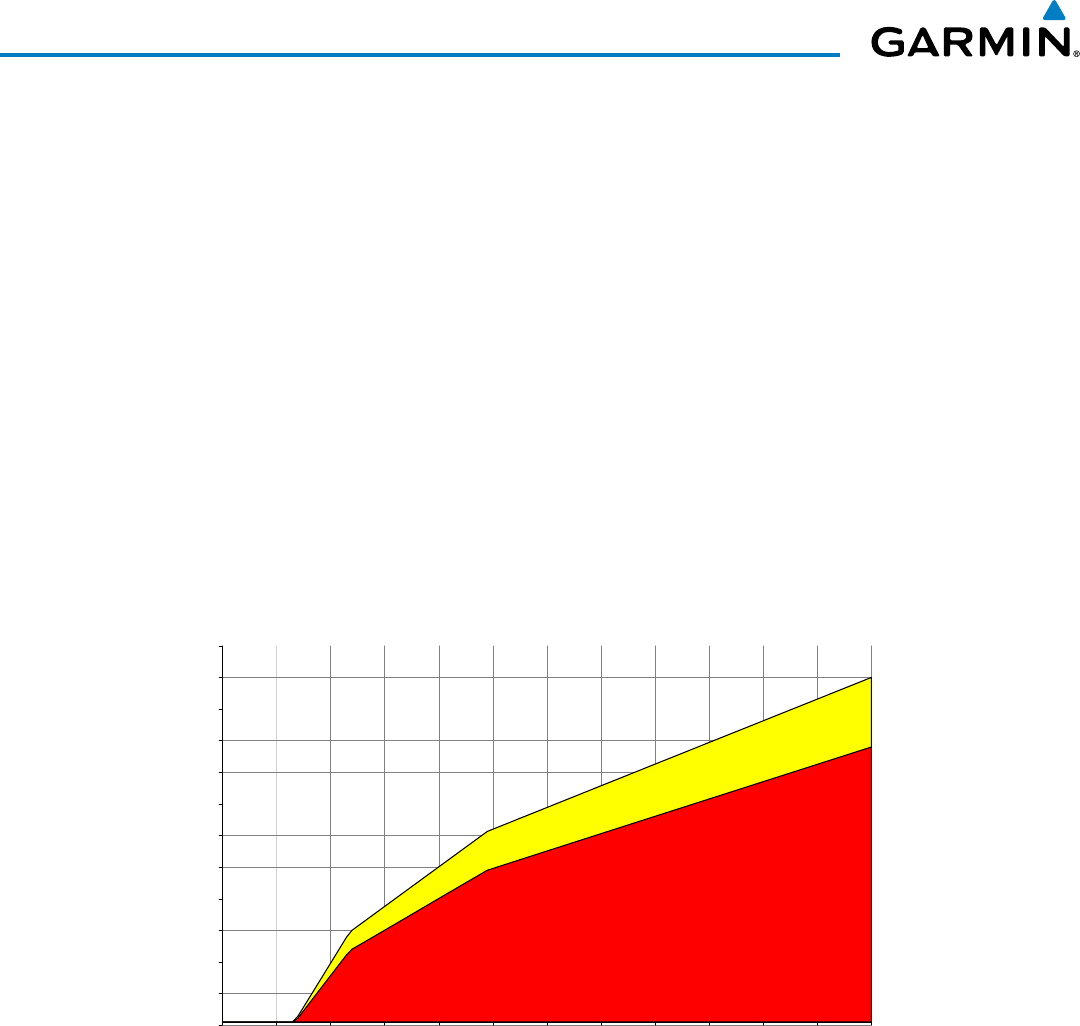
Garmin G1000 Pilot’s Guide for the Beechcraft 200/B200 Series
190-00928-04 Rev. A426
HAZARD AVOIDANCE
Inhibiting/enabling FLTA and PDA alerting:
1) Select the TAWS-A Page.
2) Select the TAWS INH Softkey to inhibit or enable TAWS-A (choice dependent on current state).
Or:
1) Press the MENU Key. (Figure 6-145)
2) Select ‘Inhibit TAWS’ or ‘Enable TAWS’ (choice dependent on current state) and press the ENT Key.
If PDA and FLTA alerts are inhibited when the Final Approach Fix is the active waypoint in a GPS SBAS
approach, a ‘LOW ALT’ annunciation may appear on the PFD next to the Altimeter if the current aircraft
altitude is at least 164 feet below the prescribed altitude at the Final Approach Fix. See the Flight Instruments
Section for details.
EXCESSIVE DESCENT RATE ALERT
The purpose of the Excessive Descent Rate (EDR) alert is to provide suitable notification when the
aircraft is determined to be closing (descending) upon terrain at an excessive speed. Figure 6-146 shows the
parameters for the alert as defined by TSO-C151b.
0
500
1000
1500
2000
2500
3000
3500
4000
4500
5000
5500
6000
0
1000
2000
3000
4000
5000
6000
7000
8000
9000
10000
11000
12000
Descent Rate (FPM)
Height Above Terrain (Feet)
Caution: “SINK RATE”
Warning: “PULL-UP”
Figure 6-146 Excessive Descent Rate Alert Criteria
EXCESSIVE CLOSURE RATE ALERT
The Excessive Closure Rate (ECR) alert provides suitable notification when the aircraft is determined to
be closing upon terrain at an excessive speed for a given aircraft gear and flap configuration.
Figures 6-147 and 6-148 show the ECR alerting criteria for flaps in the landing configuration and for all
other flight phases respectively.
ECR alerts are automatically inhibited when the aircraft is 5 nm from the nearest airport, except when FLTA
is not available (causing the TAWS N/A or TAWS FAIL annunciation to be displayed), in which case ECR
alerting will remain active until landing.
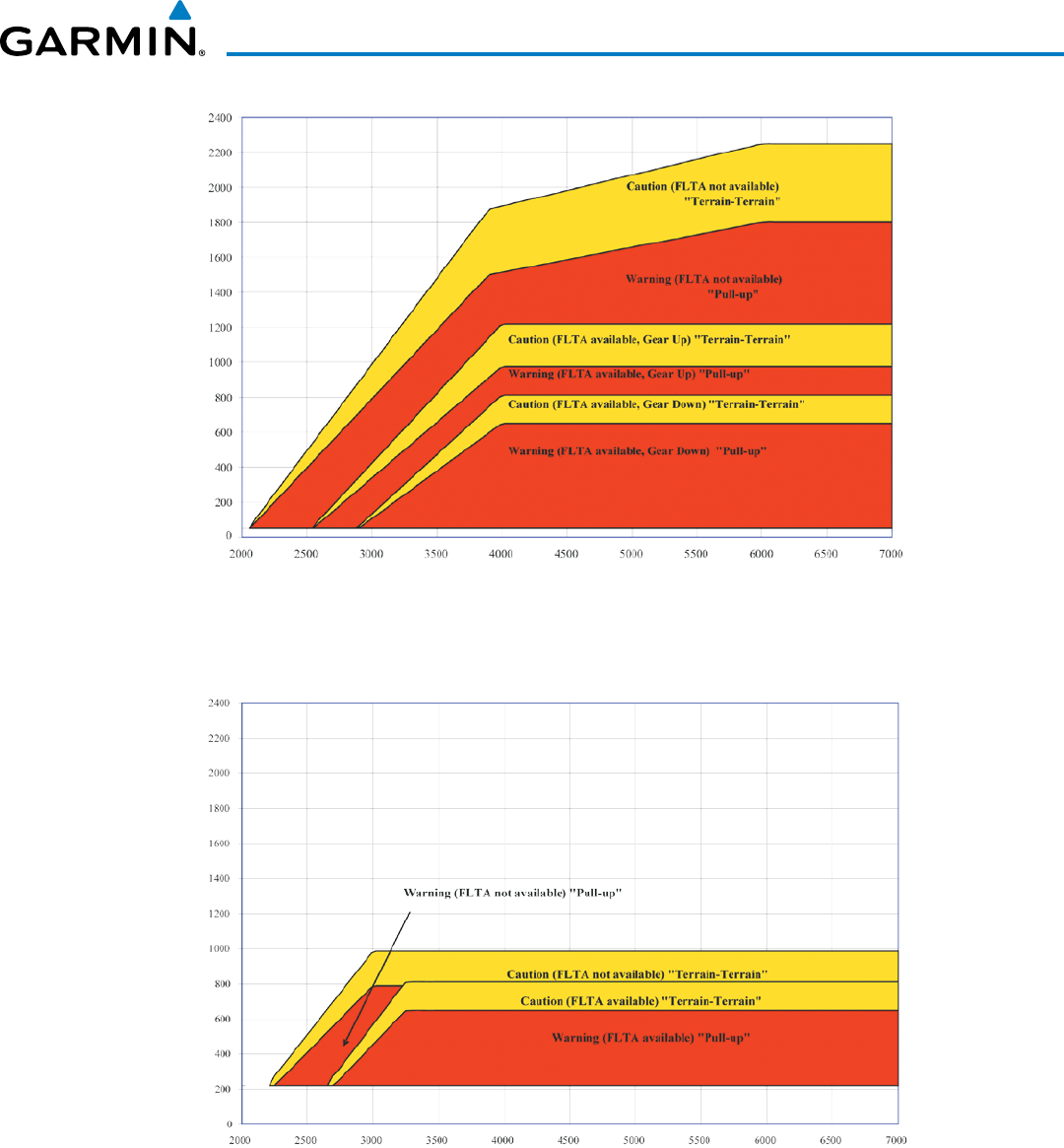
190-00928-04 Rev. A
Garmin G1000 Pilot’s Guide for the Beechcraft 200/B200 Series
427
HAZARD AVOIDANCE
Height Above Terrain (Feet)
Closure Rate (FPM)
Figure 6-147 Excessive Closure Rate Alert Criteria (Flaps Up or Takeoff Configuration)
Height Above Terrain (Feet)
Closure Rate (FPM)
Figure 6-148 Excessive Closure Rate Alert Criteria (Flaps in Landing Configuration)
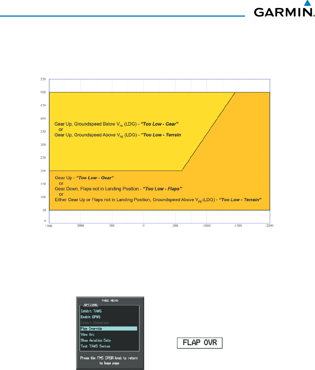
Garmin G1000 Pilot’s Guide for the Beechcraft 200/B200 Series
190-00928-04 Rev. A428
HAZARD AVOIDANCE
FLIGHT INTO TERRAIN ALERT
Flight Into Terrain (FIT) alerts occur when the aircraft is too low with respect to terrain based on landing
gear status, flap position, and groundspeed. FIT caution alerts are issued when flight conditions meet the
criteria shown in Figure 6-149.
Figure 6-149 Flight Into Terrain Caution Alert Criteria
Height Above Terrain (Feet)
Altitude Change Rate (FPM)
* Flap position will not trigger alert if Flap Override option is enabled; see discussion below.
*
*
To reduce nuisance FIT alerts on approaches where flap extension is not desired (or is intentionally delayed),
the pilot may override FIT alerting based on the flap position, while all other FIT alerting remains in effect.
Figure 6-150 TAWS-A Page Menu and FIT Flap Override Annunciation
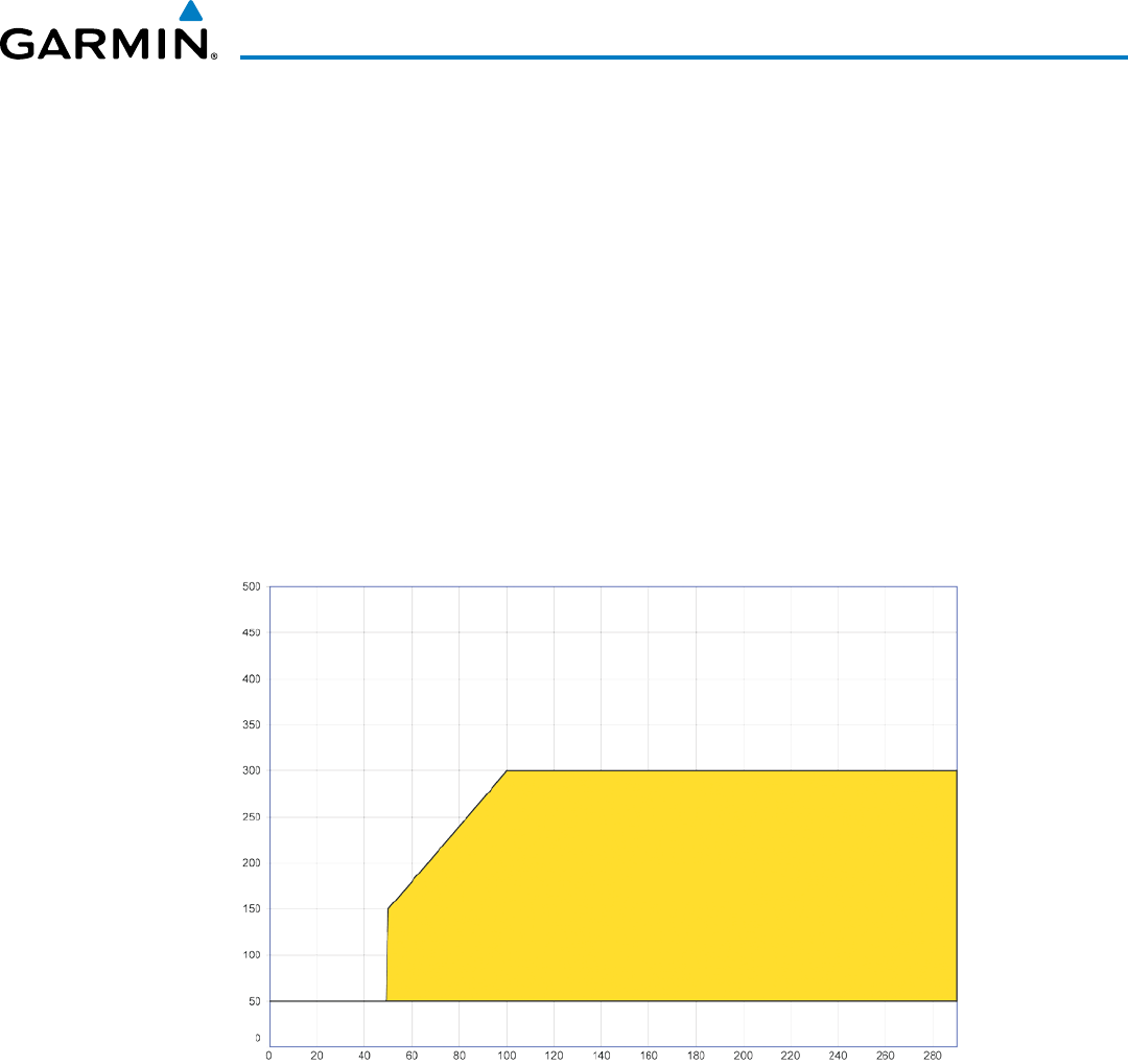
190-00928-04 Rev. A
Garmin G1000 Pilot’s Guide for the Beechcraft 200/B200 Series
429
HAZARD AVOIDANCE
Overriding Flaps-based FIT alerting:
1) Select the TAWS-A Page
2) Select the FLAP OVR Softkey
Or:
1) Press the MENU Key. (Figure 6-150)
2) Select ‘Flap Override’ or ‘Disable Flap Override’ (choice dependent on current state) and press the ENT Key.
When the Flaps Override option is enabled, the annunciation ‘FLAP OVR’ is annunciated on the PFD and
on the TAWS-A Page of the MFD (Figure 6-150). If GPWS alerts are also inhibited (which include FIT), the
‘FLAP OVR’ annunciation is not shown.
FIT alerts also occur during takeoff or go-around if the aircraft’s height above ground level (as determined
by the radar altimeter) is too close to rising terrain. TAWS-A will issue the voice alert “Too Low - Terrain”
and visual annunciations when conditions enter the caution alert area (Figure 6-151).
Figure 6-151 FIT Alerting After Takeoff
Radio Altitude Loss (Feet)
Height Above Terrain (Feet)
“TOO LOW, TERRAIN”
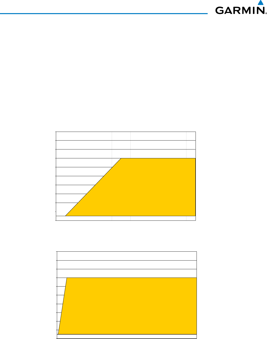
Garmin G1000 Pilot’s Guide for the Beechcraft 200/B200 Series
190-00928-04 Rev. A430
HAZARD AVOIDANCE
NEGATIVE CLIMB RATE AFTER TAKEOFF ALERT
The Negative Climb Rate (NCR) After Takeoff alert (also referred to as “Altitude Loss After Takeoff”)
provides alerts when the system determines the aircraft is losing altitude (closing upon terrain) after takeoff.
The voice alert “Don’t Sink” is given for NCR alerts, accompanied by an annunciation and a pop-up terrain
alert on the MFD if the TAWS-A Page is not already displayed. NCR alerting for TAWS-A is only active when
departing from an airport and when the following conditions are met:
• Height above the terrain is less than 700 feet
• Distance from the departure airport is 5 nm or less
• Heading change from the departure heading is less than 110 degrees
• Landing gear or flaps are configured for takeoff
NCR alerts can be triggered by either altitude loss (Figure 6-152) or sink rate (6-153).
Figure 6-152 Negative Climb Rate (NCR) Altitude Loss
0
100
200
300
400
500
600
700
800
900
1000
0 20 40 60 80 100 120 140
Altitude Loss (Feet)
Height Above Terrain (Feet)
“DON’T SINK”
or
“TOO LOW, TERRAIN”
Figure 6-153 Negative Climb Rate (NCR) Sink Rate
0
100
200
300
400
500
600
700
800
900
1000
0 500 1000 1500 2000 2500 3000 3500 4000 4500 5000 5500 6000 6500 7000
Sink Rate (FPM)
Height Above Terrain (Feet)
“DON’T SINK”
or
“TOO LOW, TERRAIN”
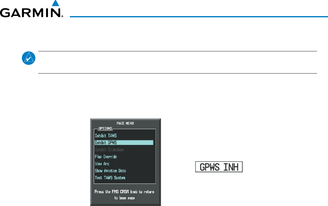
190-00928-04 Rev. A
Garmin G1000 Pilot’s Guide for the Beechcraft 200/B200 Series
431
HAZARD AVOIDANCE
inHiBiting gPWS aleRtS (eDR, ecR, Fit, anD ncR)
NOTE: The ‘Inhibit GPWS’ function only affects GPWS alerts (EDR, ECR, NCR, and FIT). Alerting for FLTA,
PDA, and GSD is controlled independently from the GPWS alerts listed below.
EDR, ECR, FIT, and NCR visual annunciations and voice alerts can be manually inhibited as a group.
Discretion should be used when inhibiting alerts and the GPWS system should be enabled when appropriate.
When these alerts are inhibited, the alert annunciation ‘GPWS INH’ is shown on the PFD and on the TAWS-A
Page annunciation window of the MFD (Figure 6-154).
Figure 6-154 TAWS-A Page Menu and GPWS Inhibit Annunciation
Inhibiting/enabling GPWS alerting:
1) Select the TAWS-A Page.
2) Select the GPWS INH Softkey to inhibit or enable GPWS alerts (choice dependent on current state).
Or:
a) Press the MENU Key. (Figure 6-154)
b) Select ‘Inhibit GPWS’ or ‘Enable GPWS’ (choice dependent on current state) and press the ENT Key.
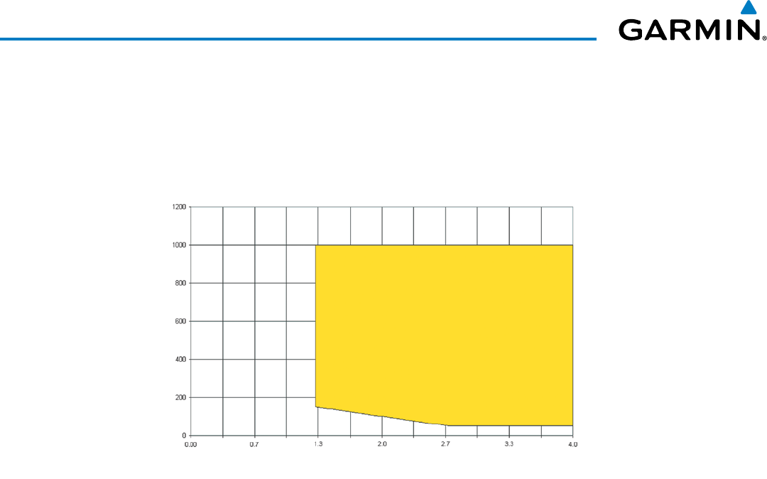
Garmin G1000 Pilot’s Guide for the Beechcraft 200/B200 Series
190-00928-04 Rev. A432
HAZARD AVOIDANCE
EXCESSIVE BELOW GLIDESLOPE/GLIDEPATH DEVIATION ALERT
A Glideslope Deviation or Glidepath Deviation (GSD) caution alert is issued when the system detects
that the aircraft is significantly below the glidepath for the selected approach in relation to the aircraft’s height
above terrain (Figure 6-155).
Radio Altitude (Feet)
Number of Dots Below Glideslope/Glidepath
Figure 6-155 Excessive Below Glideslope/Glidepath Deviation Alert Criteria
“GLIDESLOPE”
or
“GLIDEPATH”
GSD alerting is only active after departure and the following conditions are met:
• An ILS, LPV, LNAV/VNAV, or LNAV+V approach is active and vertical navigation indications are being
displayed.
• Aircraft is below 1000 feet AGL.
• Gear is configured for landing.
When a GSD caution alert occurs on an ILS approach, the visual annunciation ‘GLIDESLOPE’ is issued with
the ‘Glideslope’ voice alert. If a GSD caution alert occurs on an LPV, LNAV/VNAV, or LNAV+V approach, the
visual annunciation ‘GLIDEPATH’ is issued (Figure 6-156) with the ‘Glidepath’ voice alert.
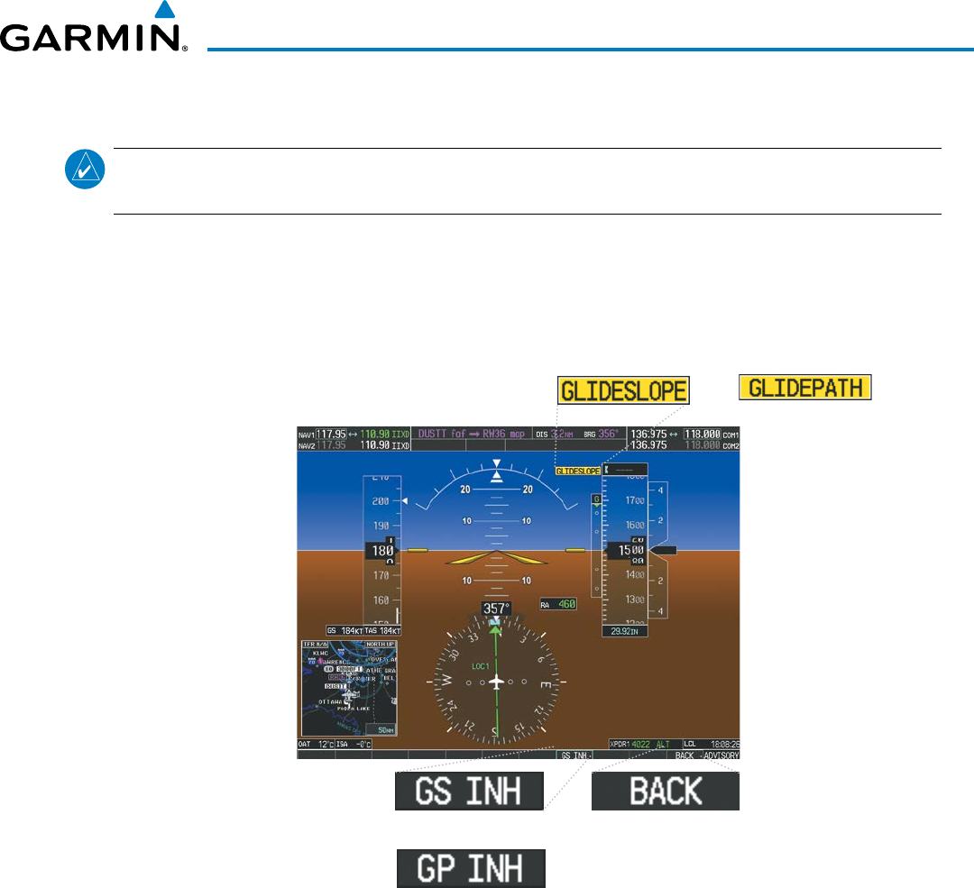
190-00928-04 Rev. A
Garmin G1000 Pilot’s Guide for the Beechcraft 200/B200 Series
433
HAZARD AVOIDANCE
inHBiting gSD aleRtS
NOTE: GSD alerting may only be inhibited while a GSD alert is occurring. GSD alerts are inhibited
independently from all other FLTA, PDA, and GPWS alerts.
During a GSD alert, the PFD Softkeys are configured as shown in Figure 6-155 to provide an option to
inhibit the alert. A ‘GLIDESLOPE’ alert will display a GS INH Softkey to inhibit the alert. A ‘GLIDEPATH’
alert will display a GP INH Softkey to inhibit the alert. When an inhibit Softkey is pressed, the PFD Softkeys
return to the top-level display. Press the BACK Softkey to return to the top level of the PFD Softkeys without
inhibiting the GSD alert.
Or:
Figure 6-156 GSD Glideslope Alert and PFD Softkeys
Or:
GSD alerts may also be inhibited on the TAWS-A Page while a GSD alert is occurring.
Inhibiting/Enabling GSD alerting (only available during a GSD alert):
1) Select the TAWS-A Page.
2) Select the GS INH or GP INH Softkey to inhibit or enable GSD alerts (softkey choice dependent on present GSD
alert type).
Or:
1) Press the MENU Key. (Figure 6-157)
2) Select the option to inhibit or enable the glideslope or glidepath alerting (choice dependent on present GSD
alert type) and press the ENT Key.
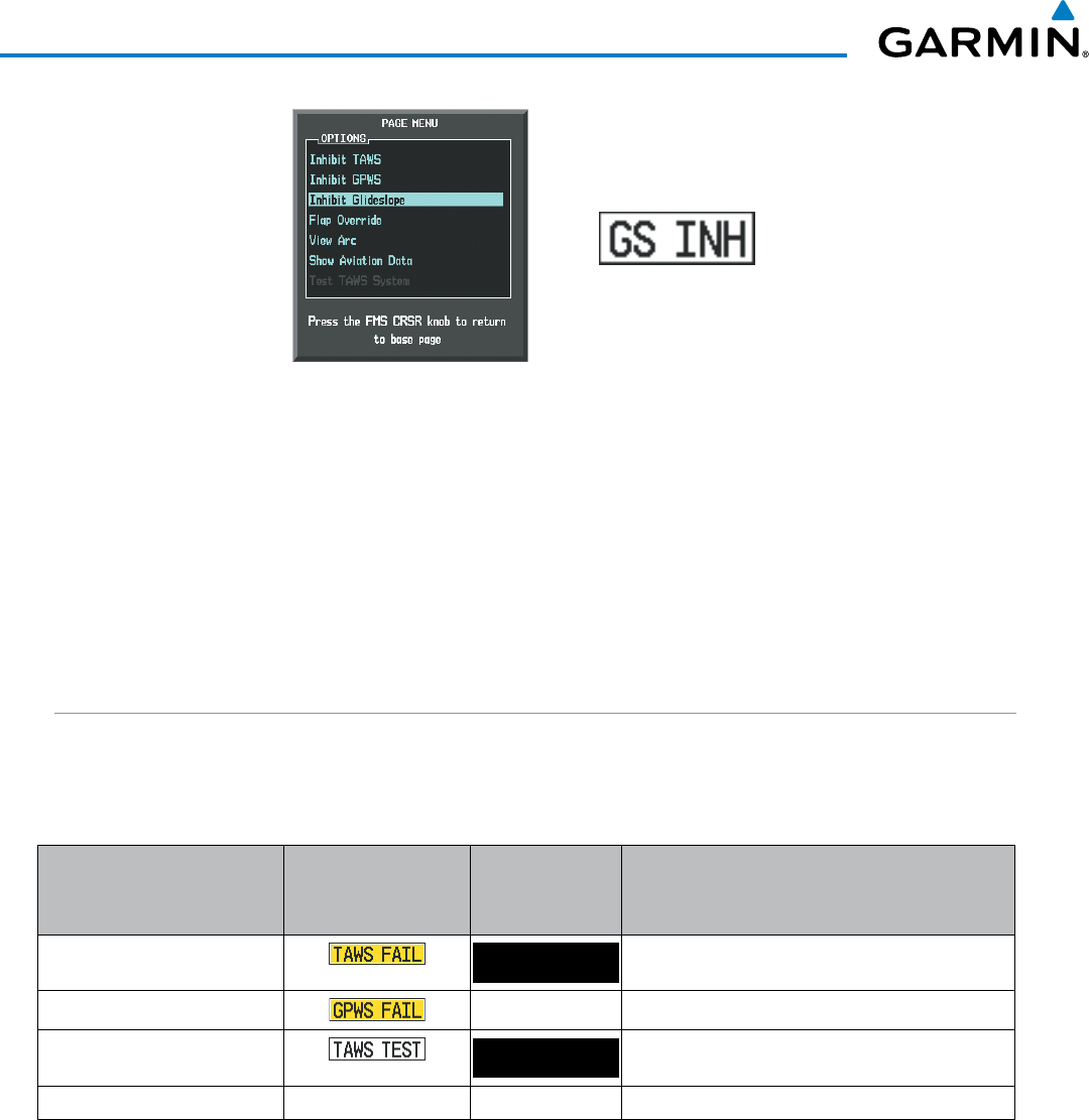
Garmin G1000 Pilot’s Guide for the Beechcraft 200/B200 Series
190-00928-04 Rev. A434
HAZARD AVOIDANCE
Figure 6-157 TAWS-A Page Menu and Glideslope Alerting Inhibited Annunciation
ALTITUDE VOICE CALLOUT (VCO)
TAWS-A provides voice alerts as the aircraft descends, beginning at 500 feet above the terrain, using radar
altitude (if greater than five nm from the nearest airport), or 500 feet above the nearest runway Touch Down
Zone Elevation using GPS-GSL altitude (if less than five nm from the nearest airport. Upon descent to this
altitude, the system issues a ‘five hundred’ voice alert.
Additional VCO alerts occur as the aircraft descends through 400, 300, 200, and 100 feet. There are no
display annunciations or pop-up alerts that accompany the voice alerts. VCO alerts cannot be inhibited.
SYSTEM STATUS
During power-up, TAWS-A conducts a system test of its alerting capabilities. The system test can also be
manually initiated. A voice alert occurs at the conclusion of the test. TAWS-A System Testing is disabled when
ground speed exceeds 30 knots. TAWS-A terrain alerts will not be issued while a test is in progress.
Alert Type PFD/MFD TAWS-A
Page Annunciation
TAWS-A Page
Center Banner
Annunciation
Voice Alert
TAWS System Fail TAWS FAIL “TAWS System Failure”
GPWS System Fail None “GPWS System Failure”
System Test in progress TAWS TEST None
System Test pass None None “TAWS System Test OK”
Table 6-21 TAWS-A System Test Status Annunciations
Manually testing the TAWS-A System:
1) Select the TAWS-A Page.
2) Press the MENU Key.
3) Select ‘Test TAWS System’ and press the ENT Key to confirm the selection. (Figure 6-158)
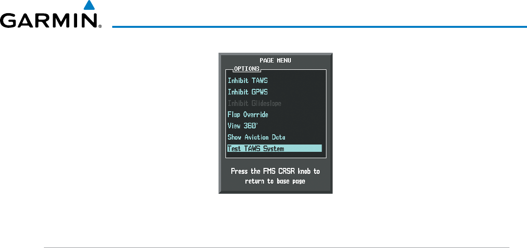
190-00928-04 Rev. A
Garmin G1000 Pilot’s Guide for the Beechcraft 200/B200 Series
435
HAZARD AVOIDANCE
Figure 6-158 TAWS-A Page Menu
TAWS-A ABNORMAL OPERATIONS
TAWS-A continually monitors several system-critical items such as database validity, flap and landing gear
position, radar altimeter input, and GPS status.
If no GDU contains Terrain, Airport Terrain, and Obstacle databases (or the databases are invalid), the voice
alert “TAWS System Failure” is generated along with the ‘TAWS FAIL’ alert annunciation.
TAWS-A requires a 3-D GPS navigation solution along with specific vertical accuracy minimums. Should the
navigation solution become degraded or if the aircraft is out of the database coverage area, the annunciation
‘TAWS N/A’ is generated in the annunciation window and on the TAWS-A Page. The voice alert “TAWS Not
Available” is also generated if airborne, and some TAWS-A terrain alerts will not be issued (Table 6-22), while
GPWS alerting (which are not dependent on GPS position) will continue to operate. When the GPS signal is re-
established and the aircraft is within the database coverage area, the voice alert “TAWS Available” is generated.
TAWS-A also requires radar altimeter input. Should the radar altimeter input fail or become degraded, the
annunciation ‘GPWS FAIL’ is generated in the annunciation window and on the TAWS-A Page. The voice alert
“GPWS System Failure” is also generated. The ‘GPWS FAIL’ annunciation will also occur if both GPS altitude
and barometric altitude are unavailable. If only the GPWS system has failed, GPWS-based alerts will not be
available (Table 6-22), while other TAWS-A alerting remains unaffected.
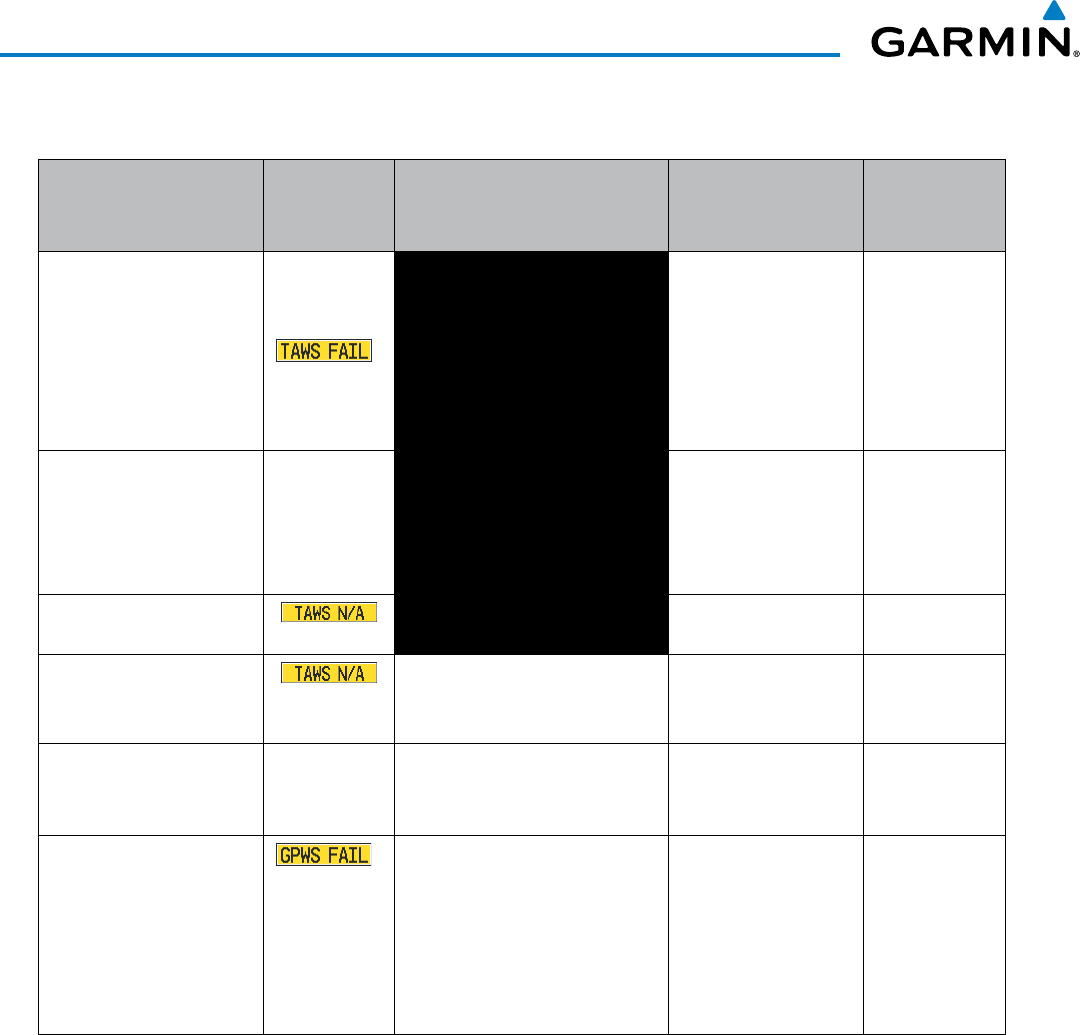
Garmin G1000 Pilot’s Guide for the Beechcraft 200/B200 Series
190-00928-04 Rev. A436
HAZARD AVOIDANCE
Alert Type
PFD/MFD
TAWS-A Page
Annunciation
TAWS-A Page Center Banner
Annunciation
Voice Alert
TAWS Alert
Types
Not Available
TAWS System Test Fail;
Terrain, Airport Terrain
or Obstacle database
unavailable or invalid on all
GDUs; software mismatch
among GDUs; TAWS audio
fault
*TAWS FAIL “TAWS System Failure” FLTA, PDA
MFD Terrain or Obstacle
database unavailable or
invalid. TAWS operating
with PFD Terrain or
Obstacle databases
None TERRAIN DATABASE FAILURE None
No GPS position NO GPS POSITION “TAWS Not Available” FLTA, PDA,
GSD
†
, VCO
*
Excessively degraded GPS
signal, or out of database
coverage area
None “TAWS Not Available” FLTA, PDA
Sufficient GPS signal
reception restored
None
None “TAWS Available”
(voice alert only in
flight)
Radar Altimeter invalid,
Vertical Speed Invalid, GPS
and Baro Altitude invalid,
Software mismatch among
GDUs, TAWS configuration
mismatch among GDUs,
TAWS audio fault
*None “GPWS System Failure” EDR, ECR, NCR,
FIT, GSD
* VCO alerts are not issued if both TAWS and GPWS systems have failed or are not available
† GSD alert will be available if a valid ILS is being used for navigation, even in no valid GPS signal is being received.
Table 6-22 TAWS-A Abnormal Status Alerts
If the aircraft bank angle exceeds 30˚, TAWS-A will disable ECR alerts. ECR alert availability returns when
the bank angle is reduced for at least eight seconds.
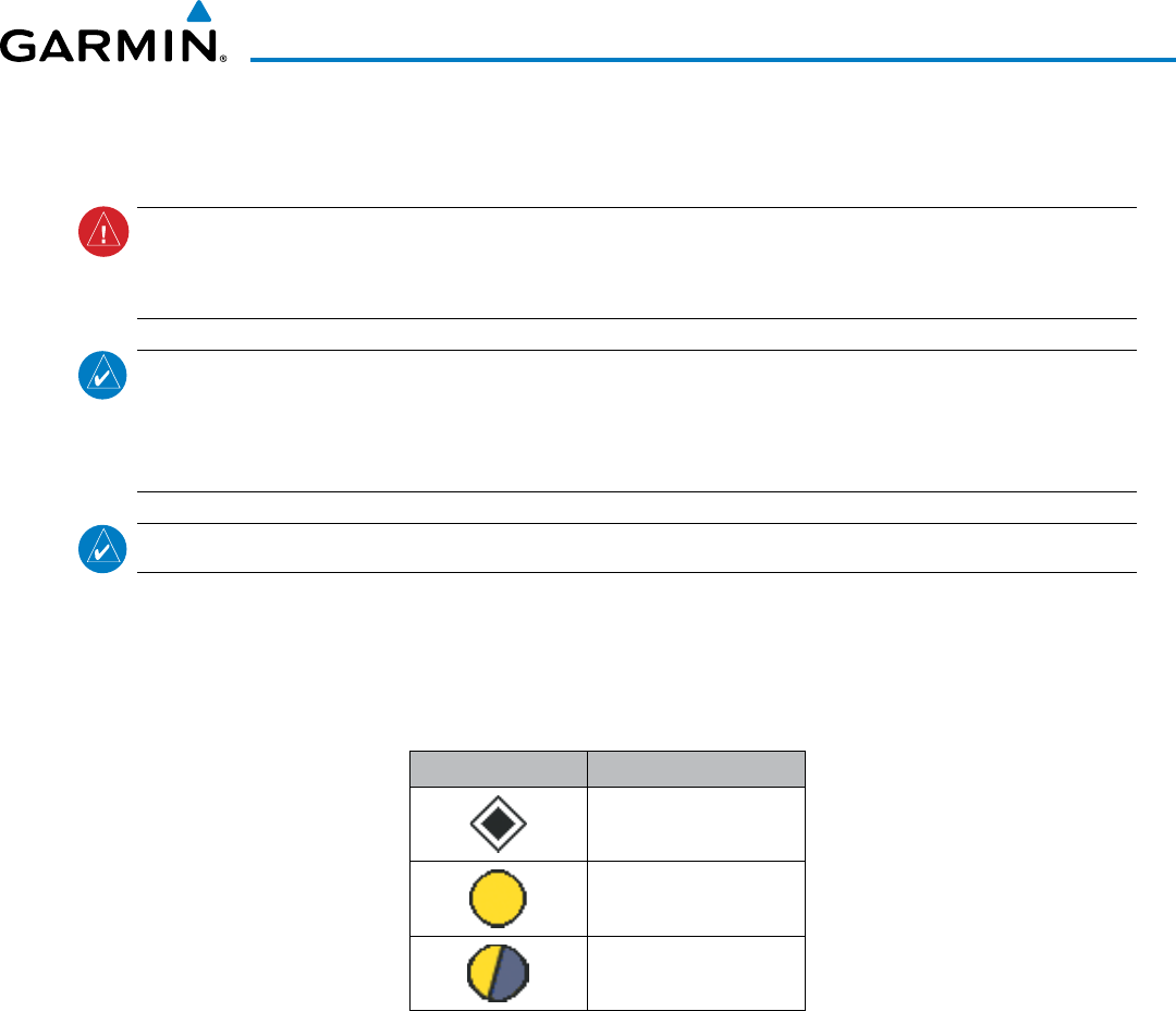
190-00928-04 Rev. A
Garmin G1000 Pilot’s Guide for the Beechcraft 200/B200 Series
437
HAZARD AVOIDANCE
6.8 TRAFFIC INFORMATION SERVICE (TIS)
WARNING: Do not rely solely upon the display of traffic information to accurately depict all of the traffic
information within range of the aircraft. Due to lack of equipment, poor signal reception, and/or inaccurate
information from other aircraft, traffic may be present but not represented on the displays.
NOTE: TIS is available only when the aircraft is within the service volume of a TIS-capable terminal radar
site. Aircraft without an operating transponder are invisible to Traffic Advisory Systems (TAS), Traffic Alert
and Collision Avoidance Systems (TCAS), and to TIS. Aircraft without altitude reporting capability are shown
without altitude separation data or climb descent indication.
NOTE: TIS is disabled if another traffic system is installed.
Traffic Information Service (TIS) is designed to help in detection and avoidance of other aircraft. TIS uses the
Mode S transponder for the traffic data link. TIS receives traffic information from ground stations, and is updated
every five seconds. The system displays up to eight traffic targets within a 7.5-nm radius, from 3000 feet below
to 3500 feet above the requesting aircraft. The system displays traffic using the symbology shown in Table 6-23.
Traffic Symbol Description
Non-Threat Traffic
Traffic Advisory (TA)
Traffic Advisory Off Scale
Table 6-23 TIS Traffic Symbols
Traffic Advisories (TA) alert the crew to intruding aircraft. When traffic meets the advisory criteria for the TA,
a solid yellow circle symbol is generated. A TA which is detected but is outside the range of the map on which
traffic is displayed are indicated with a message in the lower left corner of the map.
TIS also provides a vector line showing the direction in which the traffic is moving, to the nearest 45°. Traffic
information for which TIS is unable to determine the bearing (non-bearing traffic) is displayed in the center of the
Traffic Map Page (Figure 6-163) or in a banner at the lower left corner of maps other than the Traffic Map Page on
which traffic can be displayed (Figure 6-159).
The altitude difference between the requesting aircraft and other intruder aircraft is displayed above/below the
traffic symbol in hundreds of feet. If the other aircraft is above the requesting aircraft, the altitude separation
appears above the traffic symbol; if below, the altitude separation appears below. Altitude trend is displayed as
an up/down arrow (for speeds greater than 500 fpm in either direction) to the right of the target symbol. Traffic
symbols for aircraft without altitude reporting capability appear without altitude separation or climb/descent
information.
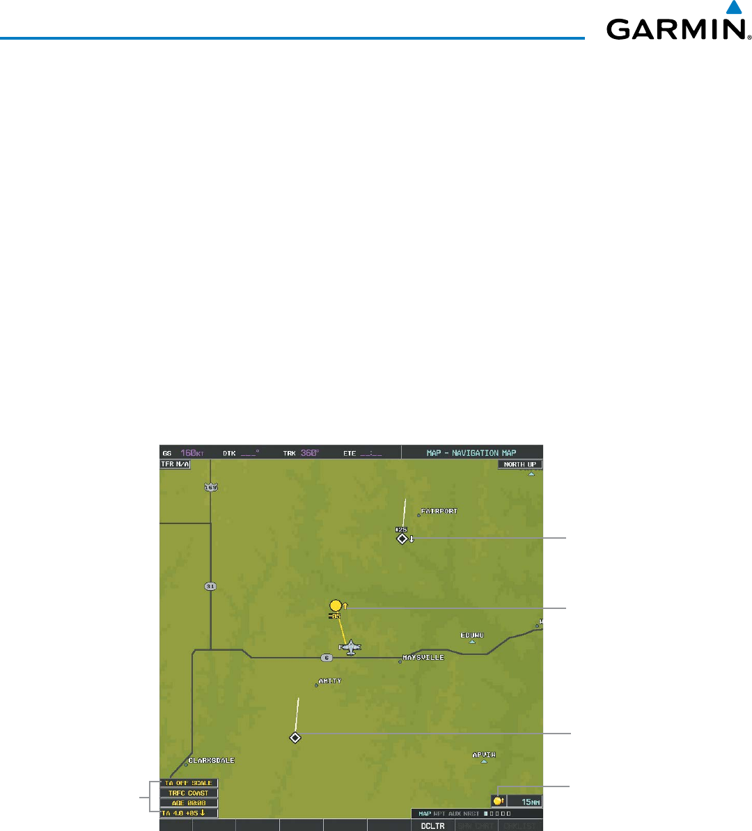
Garmin G1000 Pilot’s Guide for the Beechcraft 200/B200 Series
190-00928-04 Rev. A438
HAZARD AVOIDANCE
DISPLAYING TRAFFIC DATA
The Map - Traffic Map Page is the principal map page for viewing TIS traffic information. Traffic information
can also be displayed on the following maps (when TIS is operating) as an additional reference to the Traffic Map
Page.
• PFD Inset Map
• Navigation Map Page
• Trip Planning Page
• Nearest Pages
• Active Flight Plan Page
Traffic information is also displayed on the PFD when the Synthetic Vision Technology (SVT) option is installed
and enabled. See the Additional Features Section for details.
Displaying traffic information (maps other than the Traffic Map Page):
1) Select the MAP Softkey.
2) Select the TRAFFIC Softkey. Traffic is now displayed on the map.
When traffic is selected on maps other than the Traffic Map Page, an icon is shown to indicate the feature is
enabled for display.
Traffic Advisory, 500’
Below, Climbing
Traffic Banner
Annunciations
Figure 6-159 TIS Traffic on the Navigation Map Page
Non-Threat Traffic,
2500’ Above,
Descending
Non-Threat Traffic,
Altitude Not
Available
Traffic Display
Enabled Icon
Displaying traffic information (PFD Inset Map):
1) Select the INSET Softkey.
2) Select the TRAFFIC Softkey to display traffic data on the inset map (TRFC-1).
3) Select the softkey again to display the traffic-only inset (TRFC-2).
4) Select the softkey again to remove traffic data.
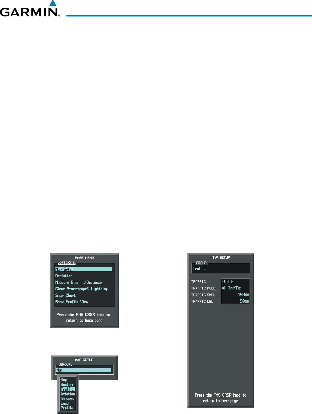
190-00928-04 Rev. A
Garmin G1000 Pilot’s Guide for the Beechcraft 200/B200 Series
439
HAZARD AVOIDANCE
The Navigation Map Page Setup Menu provides a means in addition to the softkey for enabling/disabling
display of traffic. The setup menu also controls the map range settings above which traffic data (symbols
and labels) are decluttered from the display. If a map range larger than the map range setting is selected, the
data is removed from the map. Maps besides the Traffic Map Page use settings based on those selected for the
Navigation Map Page.
Customizing traffic display on the Navigation Map Page:
1) Select the Navigation Map Page.
2) Press the MENU Key.
3) With ‘Map Setup’ highlighted, press the
ENT
Key (Figure 6-160).
4) Turn the small FMS Knob to select the ‘Traffic’ Group and press the ENT Key (Figure 6-161).
5) Turn the large
FMS
Knob or press the
ENT
Key to scroll through product selections (Figure 6-162).
• TRAFFIC – Turns the display of traffic data on or off
• TRAFFIC MODE – Selects the traffic mode for display; select from:
- All Traffic - Displays all traffic
- TA ONLY - Displays Traffic Alerts only
• TRAFFIC SMBL – Selects the maximum range at which traffic symbols are shown
• TRAFFIC LBL – Selects the maximum range at which traffic labels are shown (with the option to turn off)
6) Turn the small
FMS
Knob to scroll through options for each product (ON/OFF, range settings, etc.).
7) Press the
ENT
Key to select an option.
8) Press the FMS Knob or CLR Key to return to the Navigation Map Page with the changed settings.
Figure 6-161 Navigation Map Page Setup Menu
Figure 6-160 Navigation Map Page Menu
Figure 6-162 Navigation Map Page Setup Menu, Traffic Group
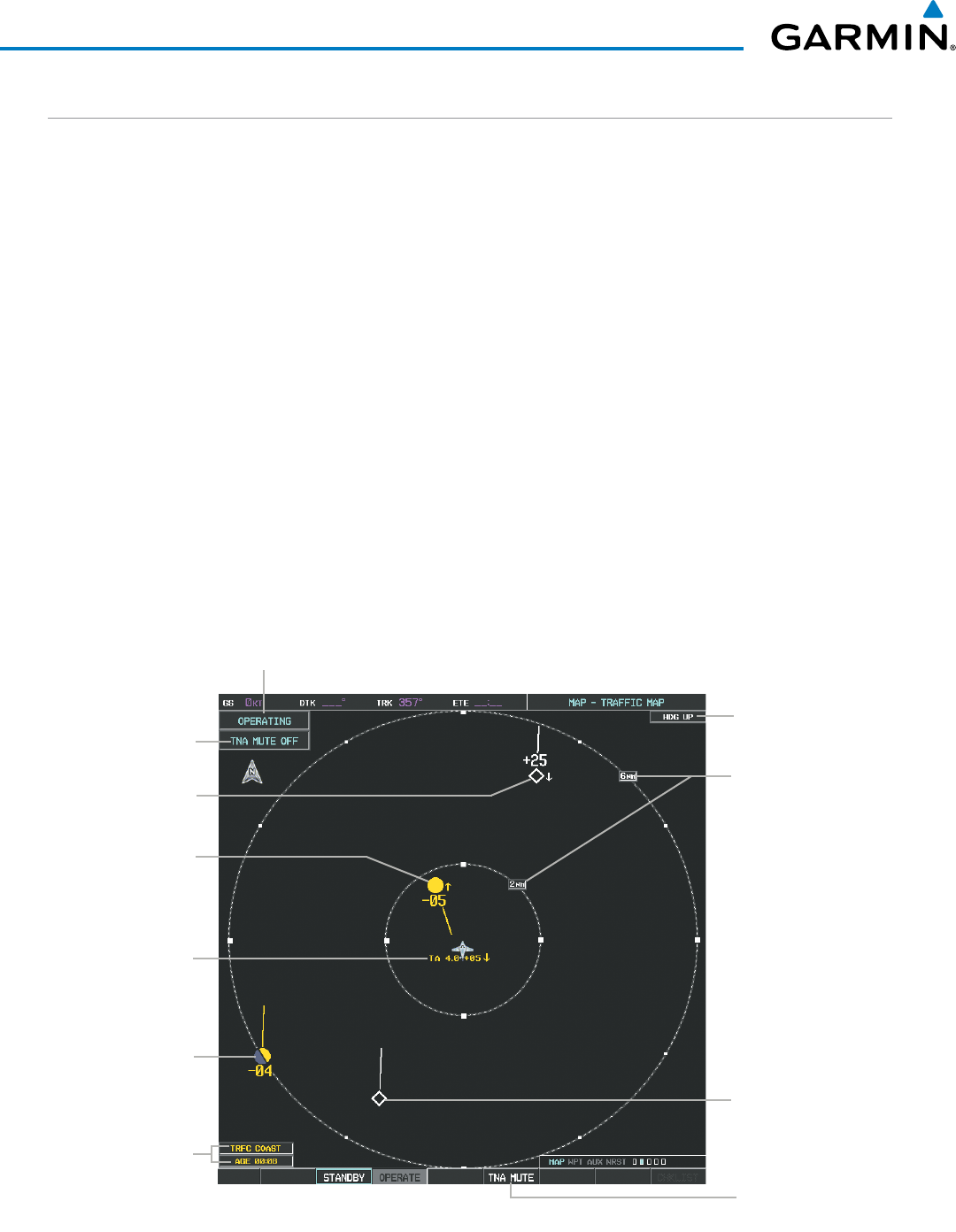
Garmin G1000 Pilot’s Guide for the Beechcraft 200/B200 Series
190-00928-04 Rev. A440
HAZARD AVOIDANCE
TRAFFIC MAP PAGE
The Traffic Map Page is specialized to show surrounding TIS traffic data in relation to the aircraft’s current
position and altitude, without clutter from the basemap. Aircraft orientation on this map is always heading up
unless there is no valid heading. Map range is adjustable with the RANGE Knob from 2 to 12 nm, as indicated
by the map range rings.
The traffic mode is annunciated in the upper left corner of the Traffic Map Page. When the aircraft is on the
ground, TIS automatically enters Standby Mode. Once the aircraft is airborne, TIS switches from Standby to
Operating Mode and the system begins to display traffic information. Refer to the System Status discussion for
more information.
Displaying traffic on the Traffic Map Page:
1) Turn the large
FMS
Knob to select the Map Page Group.
2) Turn the small
FMS
Knob
to select the Traffic Map Page.
3) Confirm TIS is in Operating Mode:
Select the
OPERATE
Softkey to begin displaying traffic.
Or:
a) Press the
MENU
Key.
b) Select ‘Operate Mode’ (shown if TIS is in Standby Mode) and press the ENT Key.
Select to Mute
“TIS Not Available”
Voice Alert
“Non-Bearing” Traffic
(TIS Unable to
Determine Bearing)
Distance is 4.0 nm,
500’ Above,
Descending
Traffic Mode Annunciation
Figure 6-163 Traffic Map Page
“TIS Not Available”
Voice Alert Status
Traffic Status Banners
Traffic Advisory Off-
Scale, 400’ Below,
Level Non-Threat Traffic,
Altitude Not
Available
Traffic Advisory, 500’
Below, Climbing
Non-Threat Traffic,
2500’ Above,
Descending
Traffic Map Range
Rings
Traffic Map Page
Orientation
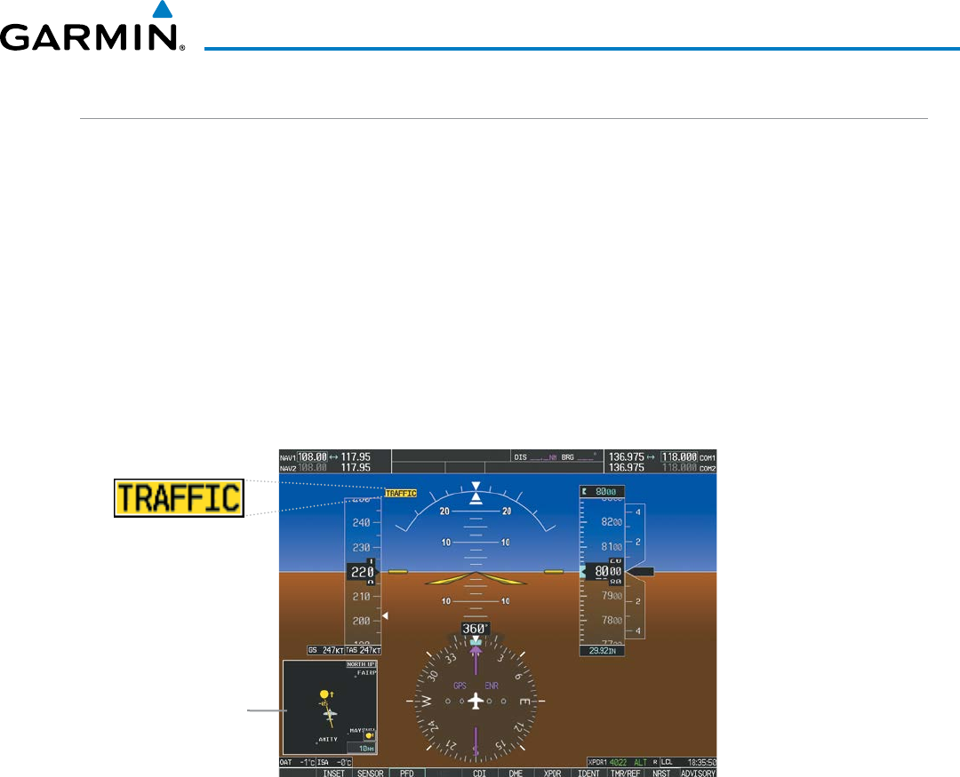
190-00928-04 Rev. A
Garmin G1000 Pilot’s Guide for the Beechcraft 200/B200 Series
441
HAZARD AVOIDANCE
TIS ALERTS
When the number of TAs detected increases from one scan to the next, the following occur:
• A single “Traffic” voice alert is generated.
• A ‘TRAFFIC’ Annunciation appears to the top left of the Attitude Indicator on the PFD, flashes for five seconds
and remaining displayed until no TAs are detected in the area.
• The PFD Inset Map is automatically displayed with traffic.
To reduce the number of nuisance alerts due to proximate aircraft, the “Traffic” voice alert is generated only
when the number of TAs increases. For example, when the first TA is displayed, a visual annunciation are
generated. As long as a single TA remains on the display, no additional voice alerts are generated. If a second
TA appears on the display or if the number of TAs initially decreases and then subsequently increases, another
voice alert is generated.
Figure 6-164 Traffic Annunciation (PFD)
Inset Map
Displays When
TA is Detected
A “TIS Not Available” (TNA) voice alert is generated when the TIS service becomes unavailable or is out of
range. TIS may be unavailable in the radar coverage area due to the following:
• Radar site TIS Mode S sensor is not operational or is out of service
• Traffic or requesting aircraft is beyond the maximum range of the TIS-capable Mode S radar site.
• Traffic or requesting aircraft is above the radar site in the cone of silence and out of range of an adjacent site.
• Traffic or requesting aircraft is below radar coverage. In flat terrain, the coverage extends from about 3000
feet upward at 55 miles. Terrain and obstacles around the radar site can further decrease radar coverage in all
directions.
• Traffic does not have an operating transponder.
The “TIS Not Available” (TNA) voice alert can be manually muted to reduce nuisance alerting. TNA muting
status is shown in the upper left corner of the Traffic Map Page.
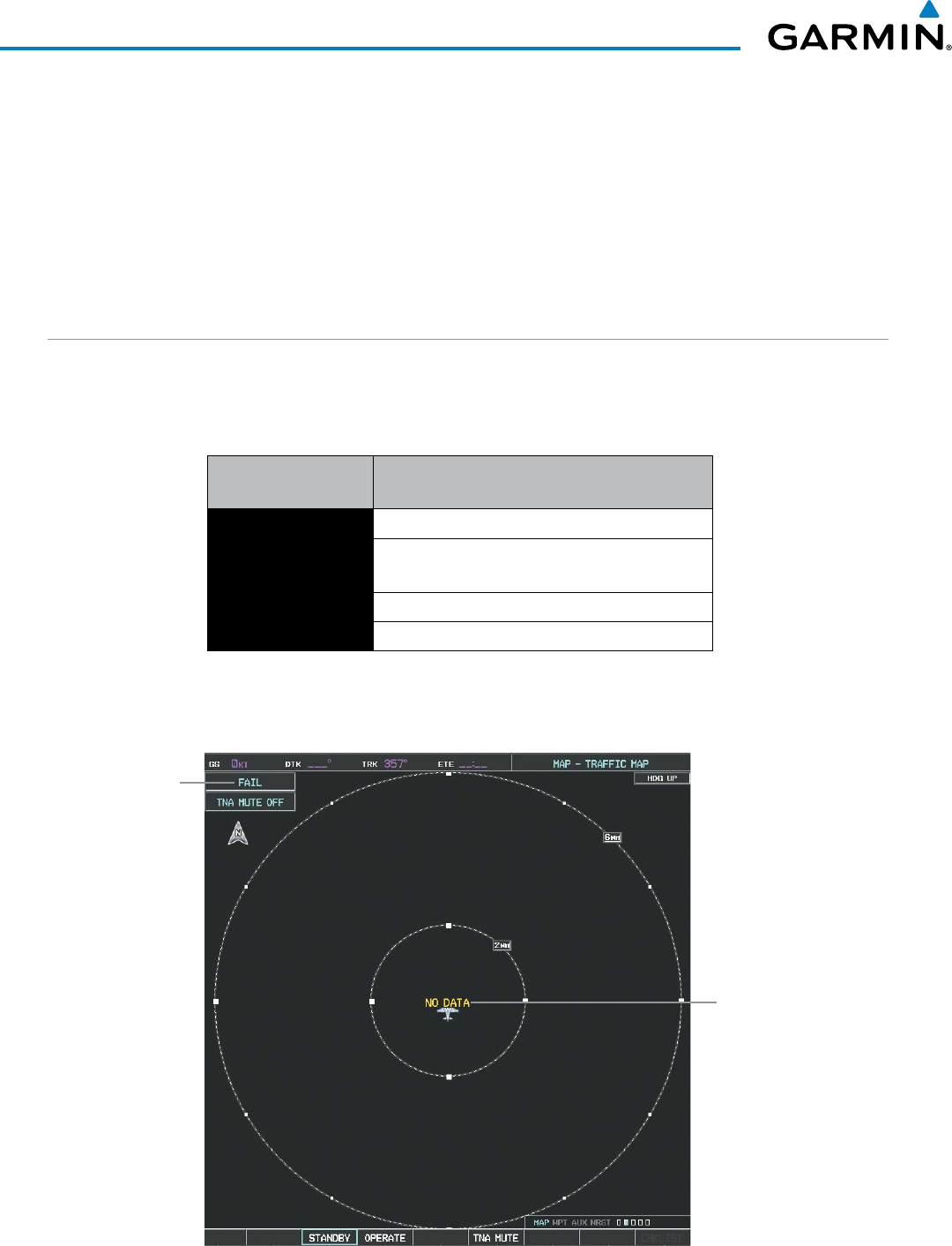
Garmin G1000 Pilot’s Guide for the Beechcraft 200/B200 Series
190-00928-04 Rev. A442
HAZARD AVOIDANCE
Muting the “TIS Not Available” voice alert:
1) Select the Traffic Map Page.
2) Select the
TNA MUTE
Softkey. The status is displayed in the upper left corner of the Traffic Map Page.
Or:
a) Press the
MENU
Key.
b) Select ’”Not Available” Mute On’ (shown if TNA muting is currently off) and press the ENT Key.
SYSTEM STATUS
The G1000 performs an automatic test of TIS during power-up. If TIS passes the test, TIS enters Standby
Mode (on the ground) or Operating Mode (in the air). If TIS fails the power up test, an annunciation is shown
in the center of the Traffic Map Page.
Traffic Map Page
Annunciation Description
NO DATA Data is not being received from the transponder*
DATA FAILED Data is being received from the transponder, but
a failure is detected in the data stream*
FAILED The transponder has failed*
UNAVAILABLE TIS is unavailable or out of range
* Contact a service center or Garmin dealer for corrective action
Table 6-24 TIS Failure Annunciations
Data Not Received
from Transponder
System Test
Failed Status
Figure 6-165 TIS Power-up Test Failure
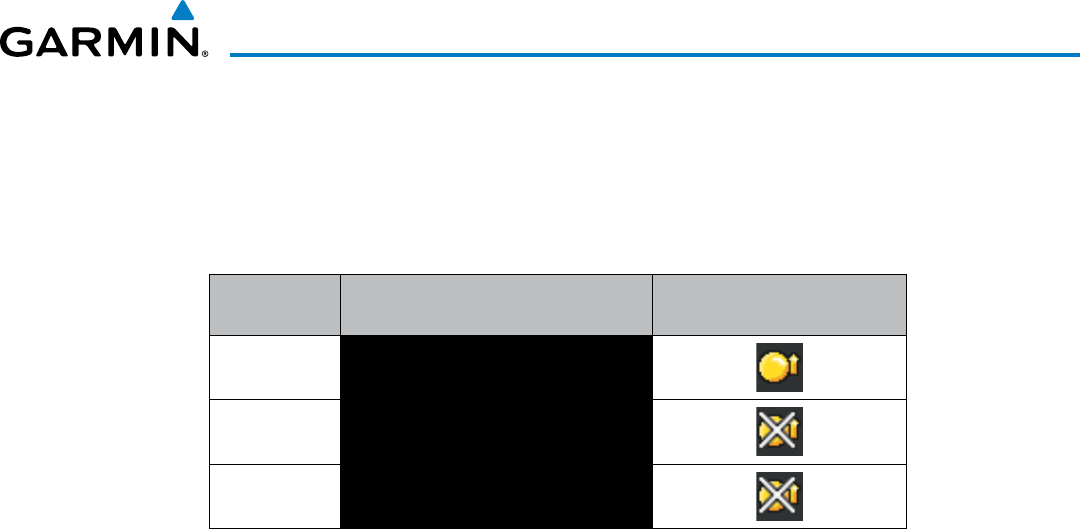
190-00928-04 Rev. A
Garmin G1000 Pilot’s Guide for the Beechcraft 200/B200 Series
443
HAZARD AVOIDANCE
The traffic mode is annunciated in the upper left corner of the Traffic Map Page. When the aircraft is on the
ground, TIS automatically enters Standby Mode. If traffic is selected for display on another map while Standby
Mode is selected, the traffic display enabled icon is crossed out (also the case whenever TIS has failed). Once
the aircraft is airborne, TIS switches to Operating Mode and traffic information is displayed. The mode can be
changed manually using softkeys or the page menu.
Mode Traffic Mode Annunciation
(Traffic Map Page)
Traffic Display Status Icon
(Other Maps)
TIS Operating OPERATING
TIS Standby STANDBY
(also shown in white in center of page)
TIS Failed* FAIL
* See Table 6-26 for additional failure annunciations
Table 6-25 TIS Modes
Switching between TIS modes:
1) Select the Traffic Map Page.
2) Select the
STANDBY
or
OPERATE
Softkey to switch between modes. The mode is displayed in the upper left
corner of the Traffic Map Page.
Or:
a) Press the
MENU
Key.
b) Select ‘Operate Mode’ or ‘Standby Mode’ (choice dependent on current state) and press the ENT Key. The
annunciations to indicate the status of traffic information appear in a banner at the lower left corner
of maps on which traffic can be displayed (Table 6-26).
Garmin G1000 Pilot’s Guide for the Beechcraft 200/B200 Series
190-00928-04 Rev. A444
HAZARD AVOIDANCE
Traffic Status Banner
Annunciation Description
TA OFF SCALE A Traffic Advisory is outside the selected display range*
Annunciation is removed when traffic comes within the selected display range
TA X.X ± XX ↕
System cannot determine bearing of Traffic Advisory**
Annunciation indicates distance in nm, altitude separation in hundreds of feet, and
altitude trend arrow (climbing/descending)
AGE MM:SS
Appears if traffic data is not refreshed within 6 seconds
If after another 6 seconds data is not received, traffic is removed from the display
The quality of displayed traffic information is reduced as the age increases
TRFC COAST The displayed data is not current (6 to 12 seconds since last message)
The quality of displayed traffic information is reduced when this message is displayed
TRFC RMVD Traffic is removed because it is too old for coasting (12 to 60 seconds since last message)
Traffic may exist within the selected display range, but it is not displayed
TRFC FAIL Traffic data has failed
NO TRFC DATA Traffic has not been detected
TRFC UNAVAIL The traffic service is unavailable or out of range
*Shown as symbol on Traffic Map Page
**Shown in center of Traffic Map Page
Table 6-26 TIS Traffic Status Annunciations
190-00928-04 Rev. A
Garmin G1000 Pilot’s Guide for the Beechcraft 200/B200 Series
445
HAZARD AVOIDANCE
6.9 GARMIN GTS 800 SERIES TRAFFIC
WARNING: The Garmin GTS 800/820/825 Traffic Advisory System (TAS) and GTS 850/855 Series Traffic Alert
and Collision Avoidance System I (TCAS I) are intended for advisory use only to aid the pilot in visually
acquiring traffic. No avoidance maneuvers should be based solely upon TAS or TCAS I traffic information.
It is the responsibility of the pilot in command to see and maneuver to avoid traffic.
WARNING: Do not rely solely upon the display of traffic information to accurately depict all of the traffic
information within range of the aircraft. Due to lack of equipment, poor signal reception, and/or inaccurate
information from other aircraft, traffic may be present but not represented on the displays.
NOTE: TIS is disabled when a TAS or TCAS I system is installed.
This section covers the optional Garmin GTS 800/820/825 Traffic Advisory System (TAS) and Garmin GTS
850/855 Traffic Alert and Collision Avoidance I System (TCAS I). Differences in these traffic systems, when
applicable, are also discussed in this section.
The Garmin GTS traffic system enhances flight crew situational awareness by displaying traffic information for
transponder-equipped aircraft. The system also provides visual annunciations and a voice traffic alerts to assist
the flight crew with efforts to visually acquire traffic.
The system is capable of tracking up to 45 intruding aircraft equipped with Mode A or C transponders, and up
to 30 intruders equipped with Mode S transponders. A maximum of 30 aircraft with the highest threat potential
can be displayed simultaneously. No traffic surveillance is provided for aircraft without operating transponders.
THEORY OF OPERATION
When the traffic system is in Operating Mode, the unit interrogates the transponders of intruding aircraft
while monitoring transponder replies. The system uses this information to derive the distance, relative bearing,
and if reported, the altitude and vertical trend for each aircraft within its surveillance range. The traffic system
then calculates a closure rate to each intruder based on the projected Closest Point of Approach (CPA). If the
closure rate meets the threat criteria for a Traffic Advisory (TA), the traffic system provides visual annunciations
and voice alerts.
TAS SURVEILLANCE VOLUME
The traffic surveillance system monitors the airspace within ±10,000 feet of own altitude, and up to 22 nm
in the forward direction (GTS 800/820/825) or up to 40 nm in the forward direction (GTS 850/855). Range is
somewhat reduced to the sides and aft of own aircraft due to the directional interrogation signal patterns. In
areas of greater transponder traffic density or when Traffic Alert and Collision and Alerting Systems II (TCAS
II) systems are detected, the system automatically reduces its interrogation transmitter power (and therefore
range) in order to limit potential interference from other signals.
When the traffic system is paired with the optional GTX 33 ES (extended squitter) transponder, the traffic
system uses Automatic Dependent Surveillance - Broadcast (ADS-B) position reports from participating
aircraft to enhance the positional accuracy of traffic displayed within the TAS or TCAS I surveillance range.
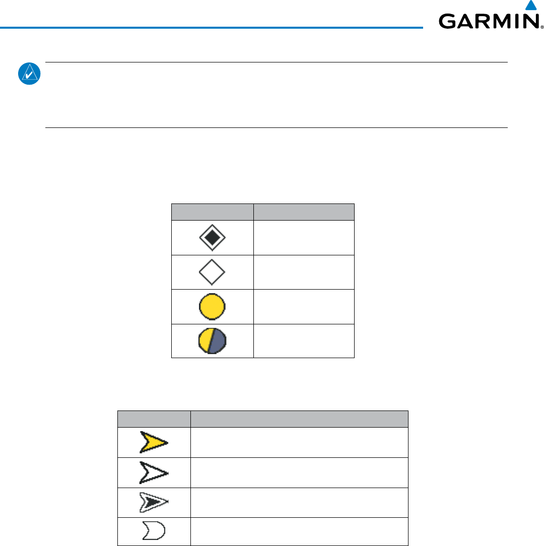
Garmin G1000 Pilot’s Guide for the Beechcraft 200/B200 Series
190-00928-04 Rev. A446
HAZARD AVOIDANCE
NOTE: Do not confuse this functionality with full ADS-B capability, which can provide traffic information
from ADS-B Ground-Based Transceivers (GBTs) and ADS-B traffic outside of the TAS surveillance volume.
This system is limited to displaying ADS-B information from suitably equipped airborne aircraft within the
TAS/TCAS I surveillance volume.
TRAFFIC DISPLAY SYMBOLOGY
The traffic system uses symbology to depict intruding traffic on the displays using the symbols shown in
Tables 6-27 and 6-28.
Traffic Symbol Description
Non-Threat Traffic
Proximity Advisory (PA)
Traffic Advisory (TA)
Traffic Advisory Off Scale
Table 6-27 Traffic Symbol Description
Traffic Symbol Description
Traffic Advisory with ADS-B directional information. Points in the
direction of the intruder aircraft track.
Proximity Advisory with ADS-B directional information. Points in
the direction of the aircraft track.
Non-threat traffic with ADS-B directional information. Points in the
direction of the intruder aircraft track.
Traffic with ADS-B directional information, but positional accuracy
is degraded. Points in the direction of the aircraft track.
Table 6-28 Traffic with ADS-B Symbology
A Traffic Advisory (TA), displayed as a yellow circle or triangle, alerts the crew to a potentially hazardous
intruding aircraft, if the closing rate, distance, and vertical separation meet TA criteria. A Traffic Advisory
that is beyond the selected display range (off scale) is indicated by a half TA symbol at the edge of the screen
at the relative bearing of the intruder.
A Proximity Advisory (PA), displayed as a solid white diamond or triangle, indicates the intruding aircraft
is within ±1200 feet and is within a 6 nm range, but is still not considered a TA threat.
A Non-threat Advisory, shown as an open white diamond or triangle, is displayed for traffic beyond 6 nm
that is neither a TA or PA.
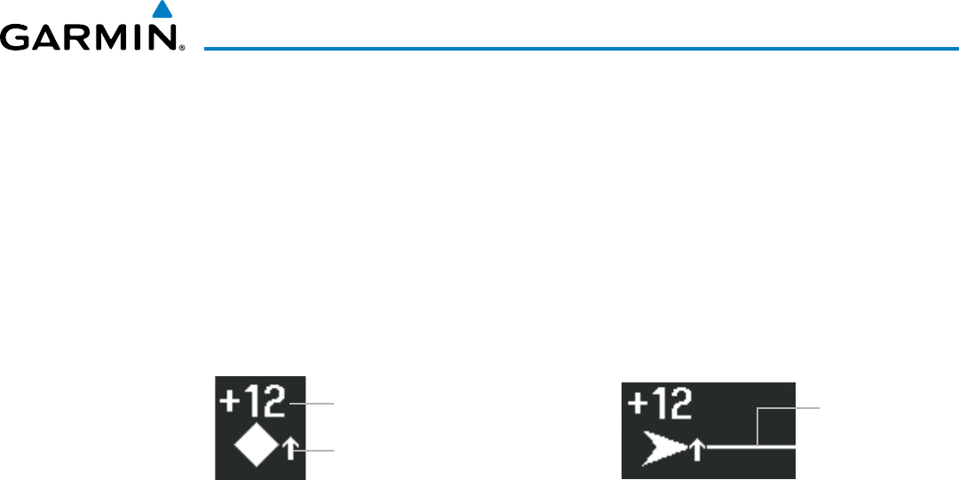
190-00928-04 Rev. A
Garmin G1000 Pilot’s Guide for the Beechcraft 200/B200 Series
447
HAZARD AVOIDANCE
A solid white rounded arrow indicates either a PA or Non-Threat traffic with ADS-B directional information,
but the position of the traffic is shown with degraded accuracy.
Relative altitude, when available, is displayed above or below the corresponding intruder symbol in
hundreds of feet (Figures 6-166, 6-167). When this altitude is above own aircraft, it is preceded by a ‘+’
symbol; a minus sign ‘-’ indicates traffic is below own aircraft.
The system displays the altitude vertical trend as an up/down arrow (for speeds greater than 500 fpm in
either direction) to the right of the intruder symbol (Figures 6-166, 6-167).
If the intruding aircraft is providing ADS-B track information, this is displayed as a vector line extending
beyond the traffic symbol in the direction of the track (Figure 6-167).
Relative Altitude
Vertical trend arrow
Figure 6-166 Intruder Altitude and
Vertical Trend Arrow
Vector Line
indicates
intruder
aircraft track
Figure 6-167 Intruder Traffic with ADS-B
Directional Information and Track
The traffic system automatically suppresses the display of altitude-reporting aircraft on the ground under
either of the following conditions:
• On-ground aircraft is equipped with a Mode S transponder.
• On-ground aircraft is equipped with a Mode C transponder, and own aircraft’s radar altimeter (if installed)
is displaying 1700’ AGL or less.

Garmin G1000 Pilot’s Guide for the Beechcraft 200/B200 Series
190-00928-04 Rev. A448
HAZARD AVOIDANCE
TA ALERTING CONDITIONS
The traffic system automatically adjusts its TA sensitivity level to reduce the likelihood of nuisance TA
alerting during flight phases likely to be near airports. Level A (less) TA sensitivity is used when the aircraft’s
landing gear is extended, or when the radar altimeter (if equipped) indicates own aircraft is below 2000’ AGL.
In all other conditions, Level B (greater) TA sensitivity is used to assess TA threats.
Sensitivity
Level
Intruder Altitude
Available
TA Alerting Conditions
AYes
Intruder closing rate provides less than 20 seconds of vertical and
horizontal separation.
Or:
Intruder closing rate provides less than 20 seconds of horizontal
separation and vertical separation is within 600 feet.
Or:
Intruder range is within 0.2 nm and vertical separation is within
600 feet.
A No Intruder closing rate provides less than 15 seconds of separation.
BYes
Intruder closing rate provides less than 30 seconds of vertical and
horizontal separation.
Or:
Intruder closing rate provides less than 30 seconds of horizontal
separation and vertical separation is within 800 feet.
Or:
Intruder range is within 0.55 nm and vertical separation is within
800 feet.
B No Intruder range is less than 20 seconds.
Table 6-29 TA Sensitivity Level and TA Alerting Criteria
TRAFFIC ALERTS
When the traffic system detects a new TA, the following occur:
• A single “Traffic!” voice alert is generated, followed by additional voice information about the bearing, relative
altitude, and approximate distance from the intruder that triggered the TA (Table 6-30). The voice alert,
“Traffic! 12 o’clock, high, four miles,” indicates the traffic is in front of own aircraft, above own altitude,
and approximately four nautical miles away.
• A ‘TRAFFIC’ Annunciation appears at the top right of the airspeed on the PFD, flashes for five seconds, and
remains displayed until no TAs are detected in the area (Figure 6-168).
• The PFD Inset Map is automatically displayed with TA traffic.
If the bearing of TA traffic cannot be determined (Figures 6-170 and 6-173), a yellow text banner will be
displayed in the center of the Traffic Map Page and in the lower-left of the PFD inset map instead of a TA
symbol. The text will indicate “TA” followed by the distance, relative altitude, and vertical trend arrow for the
TA traffic, if known.
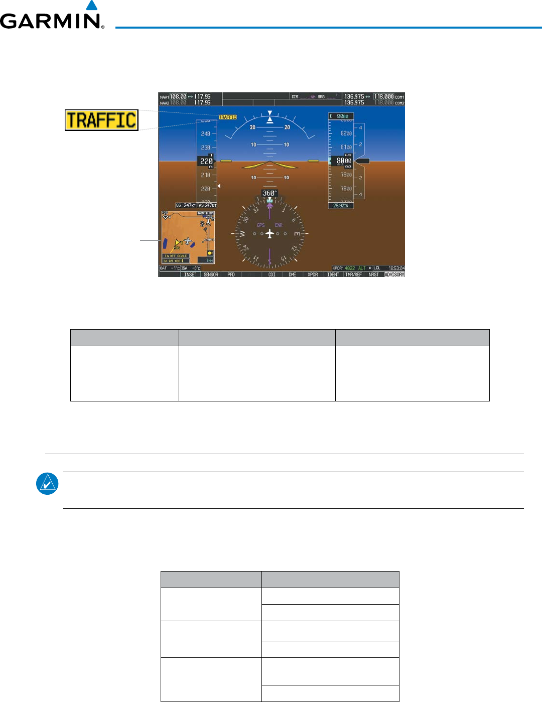
190-00928-04 Rev. A
Garmin G1000 Pilot’s Guide for the Beechcraft 200/B200 Series
449
HAZARD AVOIDANCE
A TA will be displayed for at least eight seconds, even if the condition(s) that initially triggered the TA are no
longer present.
Figure 6-168 Traffic Annunciation (PFD)
Inset Map
Displays When
TA is Detected
Bearing Relative Altitude Distance (nm)
“One o’clock” through
“Twelve o’clock”
or “No Bearing”
“High”, “Low”, “Same Altitude” (if
within 200 feet of own altitude), or
“Altitude not available”
“Less than one mile”,
“One Mile” through “Ten Miles”, or
“More than ten miles”
Table 6-30 TA Descriptive Voice Announcements
SYSTEM TEST
NOTE: Traffic surveillance is not available during the system test. Use caution when performing a system
test during flight.
The traffic system provides a system test mode to verify the system is operating normally. The test takes ten
seconds to complete. When the system test is initiated, a test pattern of traffic symbols is displayed on the
Traffic Map Page (Figure 6-169). The system issues a voice alert when the test is complete.
Traffic System Voice Alert
GTS 800/820/825 (TAS) “TAS System Test Passed.”
“TAS System Test Failed.”
GTS 850 (TCAS I) “TCAS System Test Passed.”
“TCAS System Test Failed.”
GTS 855 (TCAS I) “TCAS One System Test Passed.”
“TCAS One System Test Failed.”
Table 6-31 System Test Voice Alerts
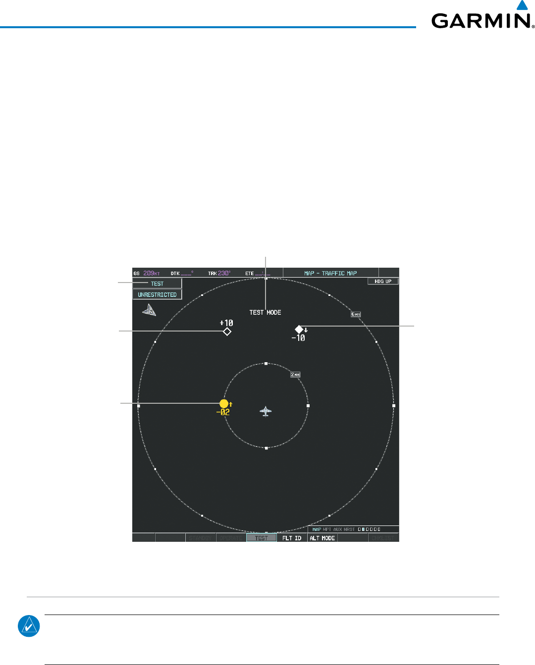
Garmin G1000 Pilot’s Guide for the Beechcraft 200/B200 Series
190-00928-04 Rev. A450
HAZARD AVOIDANCE
When the system test is complete, the traffic system enters Standby Mode.
Testing the traffic system:
1) Turn the large
FMS
Knob to select the Map Page Group.
2) Turn the small
FMS
Knob
to select the Traffic Map Page.
3) Turn the Range knob to set the range to 2/6 nm to allow for full traffic test pattern display.
4) Select the TEST Softkey.
Or:
1) Press the MENU Key and turn the small
FMS
knob
to select ‘Test Mode’.
2) Press the ENT Key.
TA at 9 o’clock,
Distance 2.0
nm, 200’ Below,
Climbing
Non-Threat
Traffic at
11 o’clock,
Distance 3.6
nm, 1000’
Above, Level
Proximity
Traffic at
1 o’clock,
Distance
3.6 nm,
1000’ Below,
Descending
Operating
Mode
Test Mode
Annunciation
Figure 6-169 System Test in Progress with Test Pattern
OPERATION
NOTE: The traffic system automatically transitions from STANDBY to OPERATE mode eight seconds after
takeoff. The system also automatically transitions from OPERATE to STANDBY mode 24 seconds after
landing.
After power-up, the traffic system is in Standby Mode. The system must be in Operating Mode for traffic to
be displayed and for TAs to be issued.
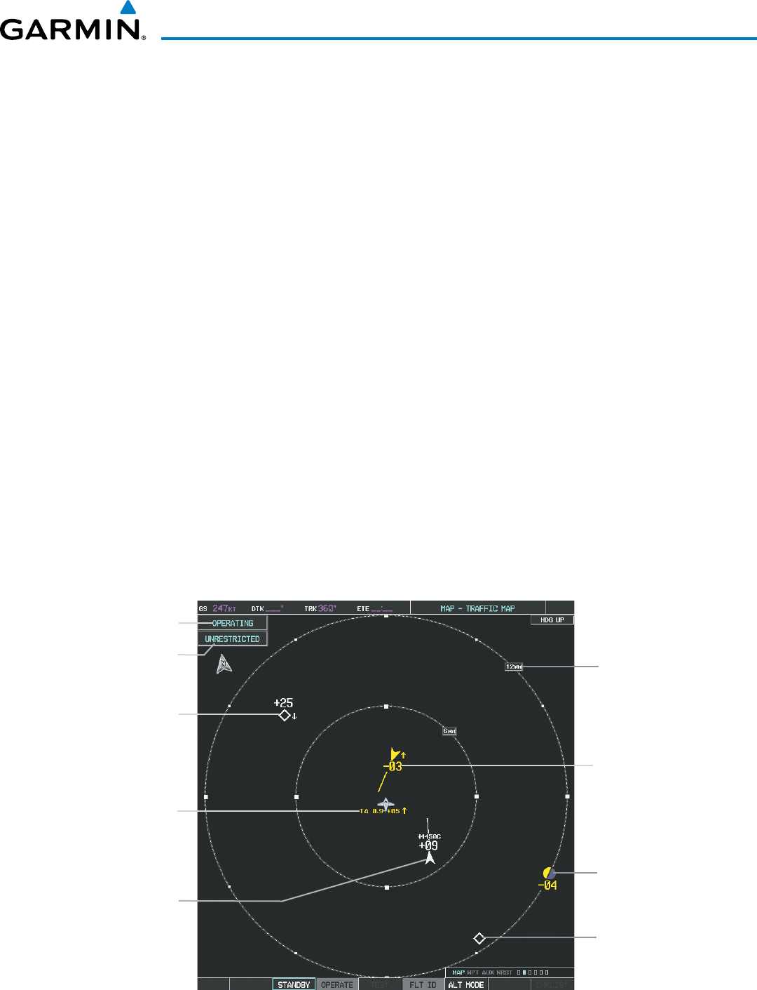
190-00928-04 Rev. A
Garmin G1000 Pilot’s Guide for the Beechcraft 200/B200 Series
451
HAZARD AVOIDANCE
Selecting the OPERATE Softkey allows the system to switch from Standby Mode to Operating Mode as
necessary. Selecting the STANDBY Softkey causes the system to enter Standby Mode.
Switching from operating mode to standby mode:
On the Traffic Page, select the
STANDBY
Softkey
Or:
1) Press the MENU Key and turn the small
FMS
knob
to select ‘Standby Mode’.
2) Press the ENT Key.
Switching from standby mode to operating mode:
On the Traffic Map Page, select the
OPERATE
Softkey.
Or:
1) Press the MENU Key and turn the small
FMS
knob
to select ‘Operate Mode’.
2) Press the ENT Key. The traffic system switches from Standby Mode to Operating Mode as necessary.
TRAFFIC MAP PAGE
The Map - Traffic Map Page shows surrounding traffic data in relation to the aircraft’s current position
and altitude, without basemap clutter. It is the principal map page for viewing traffic information. Aircraft
orientation is always heading up unless there is no valid heading. Map range is adjustable with the RANGE
Knob (up to 12 nm for the GTS 800, and up to 40 nm for the GTS 820/825/855), as indicated by the map
range rings.
The traffic mode and altitude display mode are annunciated in the upper left corner of the page.
Figure 6-170 Traffic Map Page
Operating
Mode
Altitude
Mode
Traffic Advisory,
with ADS-B
Directional
Information,
300’ Below,
Climbing
Off Scale Traffic
Advisory, 400’
Below, Level
“No Bearing”
Traffic (Bearing
Undetermined),
Distance 0.9
nm, 500’ Above,
Climbing
Proximity Traffic
with ADS-B
Directional
Information,
900’ Above,
Level
Traffic Map
Display Range
Non-Threat
Traffic, 2500’
Above,
Descending
Non-Threat Traffic,
Altitude Not
Reported

Garmin G1000 Pilot’s Guide for the Beechcraft 200/B200 Series
190-00928-04 Rev. A452
HAZARD AVOIDANCE
Displaying traffic on the Traffic Map Page:
1) Turn the large
FMS
Knob to select the Map Page Group.
2) Turn the small
FMS
Knob
to select the Traffic Map Page.
3) Select the OPERATE Softkey to begin displaying traffic. OPERATING is displayed in the Traffic mode field.
4) Select the STANDBY Softkey to place the system in the Standby mode. STANDBY is displayed in the Traffic
mode field.
5) Turn the RANGE Knob clockwise to display a larger area or counter-clockwise to display a smaller area.
altituDe DiSPlay
The pilot can select the volume of airspace in which non-threat and proximity traffic is displayed. TAs
occurring outside of these limits will always be shown.
Changing the altitude range:
1) On the Traffic Map Page, select the
ALT MODE
Softkey.
2) Select one of the following Softkeys:
• ABOVE: Displays non-threat and proximity traffic from 9000 feet above the aircraft to 2700 feet below the
aircraft. Typically used during climb phase of flight.
• NORMAL: Displays non-threat and proximity traffic from 2700 feet above the aircraft to 2700 feet below
the aircraft. Typically used during enroute phase of flight.
• BELOW: Displays non-threat and proximity traffic from 2700 feet above the aircraft to 9000 feet below the
aircraft. Typically used during descent phase of flight.
• UNREST (unrestricted): All traffic is displayed from 9900 feet above and 9900 feet below the aircraft.
3) To return to the Traffic Page, select the BACK Softkey.
Or:
1) Press the MENU Key.
2) Turn the small
FMS
Knob
to select one of the following (see softkey description in step 2 above):
• ABOVE
• NORMAL
• BELOW
• UNRESTRICTED
3) Select the ENT Softkey.
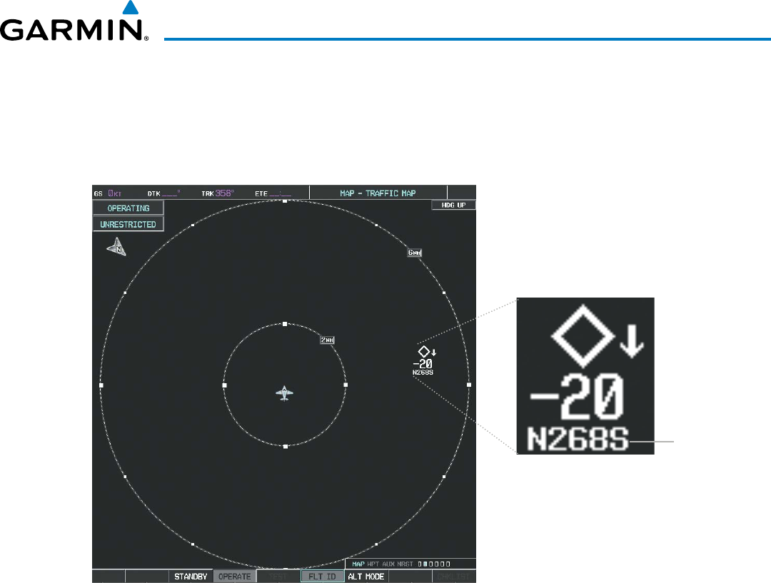
190-00928-04 Rev. A
Garmin G1000 Pilot’s Guide for the Beechcraft 200/B200 Series
453
HAZARD AVOIDANCE
FligHt iD DiSPlay
The Flight IDs of other aircraft (when available) can be enabled for display on the Traffic Map Page
(Figure 6-171). When a flight ID is received, it will appear above or below the corresponding traffic symbol
on the Traffic Map Page when this option is enabled.
Figure 6-171 Traffic Map Page with Flight IDs Enabled
Flight ID
Enabling/Disabling Flight ID Display:
On the Traffic Map Page, select the
FLT ID
Softkey.
Or:
1) Press the MENU Key.
2) Turn the small
FMS
Knob
to select ‘Show Flight IDs’ or ‘Hide Flight IDs’ (choice dependent on current state)
(Figure 6-172).
3) Press the ENT Key.

Garmin G1000 Pilot’s Guide for the Beechcraft 200/B200 Series
190-00928-04 Rev. A454
HAZARD AVOIDANCE
Figure 6-172 Traffic Map Page Menu
tRaFFic MaP Page DiSPlay Range
The display range on the Traffic Map Page can be changed at any time. Map range is adjustable with the
RANGE Knob from 2 to 40 nm, as indicated by the map range rings.
Changing the display range on the Traffic Map Page:
1) Turn the RANGE Knob.
2) The following range options are available:
• 2 nm
• 2 and 6 nm
• 6 and 12 nm
• 12 and 24 nm (GTS 820/825/850/855 only)
• 24 and 40 nm (GTS 820/825/850/855 only)
ADDITIONAL TRAFFIC DISPLAYS
Traffic information can be displayed on the following maps on the MFD when the unit is operating:
• Navigation Map Page
• Traffic Map Page
• Trip Planning Page
• Nearest Pages
• Active Flight Plan Page
Traffic information can also be displayed on the PFD when the Synthetic Vision Technology (SVT) option
is installed and enabled. See the Additional Features Section for details.
Displaying traffic information (MFD maps other than the Traffic Map Page):
1) Select the MAP Softkey.
2) Select the TRAFFIC Softkey. Traffic is now displayed on the map.
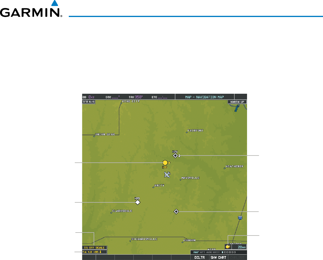
190-00928-04 Rev. A
Garmin G1000 Pilot’s Guide for the Beechcraft 200/B200 Series
455
HAZARD AVOIDANCE
When traffic is selected on maps other than the Traffic Map Page, a traffic icon is shown to indicate traffic
is enabled for display (Figure 6-173).
Displaying traffic on the Navigation Map
1) Ensure the traffic system is operating. With the Navigation Map displayed, select the
MAP
Softkey.
2) Select the
TRAFFIC
Softkey. Traffic is now displayed on the map as shown in the figure.
“No Bearing”
Traffic Advisory
Traffic Advisory
Off-Scale
Non-Threat
Traffic, 2500’
Above,
Descending
Traffic Advisory,
500’ Below,
Climbing
Proximity Traffic,
900’ Above,
Level Non-Threat
Traffic, Altitude
Not Available
Traffic Display
Enabled Icon
Figure 6-173 Traffic on the Navigation Map Page
Customizing the traffic display on the Navigation Map Page:
1) Select the Navigation Map Page.
2) Press the MENU Key.
3) With Map Setup highlighted, press the
ENT
Key (Figure 6-174).
4) Turn the small FMS Knob to select the Traffic Group and press the ENT Key (Figure 6-175).
5) Turn the large
FMS
Knob or press the
ENT
Key to scroll through the selections (Figure 6-176).
• TRAFFIC – Turns the display of traffic data on or off
• TRAFFIC MODE – Selects the traffic mode for display; select from:
- All Traffic - Displays all traffic
- TA/PA - Displays Traffic Advisories and Proximity Advisories
- TA ONLY - Displays Traffic Advisories only
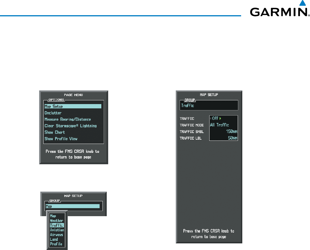
Garmin G1000 Pilot’s Guide for the Beechcraft 200/B200 Series
190-00928-04 Rev. A456
HAZARD AVOIDANCE
• TRAFFIC SMBL – Selects the maximum range at which traffic symbols are shown
• TRAFFIC LBL – Selects the maximum range at which traffic labels are shown with the option to turn off
6) Turn the small
FMS
Knob to scroll through options (ON/OFF, range settings, etc.).
7) Press the
ENT
Key to select an option.
8) Press the FMS Knob or CLR Key to return to the Navigation Map Page.
Figure 6-175 Navigation Map Page Setup Menu
Figure 6-174 Navigation Map Page Menu
Figure 6-176 Navigation Map Page Setup Menu, Traffic Group
The Navigation Map Page Setup Menu also controls the display of traffic. The setup menu controls the map
range settings. Traffic data symbols and labels can be decluttered from the display. If a map range larger than
the map range setting is selected, the data is removed from the map. Maps besides the Traffic Map Page use
settings based on those selected for the Navigation Map Page.
Traffic information can also be displayed on the PFD Inset Map by pressing the INSET Softkey. A traffic map
will appear in heading up orientation. Traffic information can also be overlaid with navigation, topographic
and optional datalink weather information.
Displaying traffic information (PFD Inset Map):
1) Select the INSET Softkey.
2) Select the TRAFFIC Softkey to display traffic data on the inset map (TRFC-1).
3) Select the softkey again to display the traffic-only inset (TRFC-2).
4) Select the softkey again to remove traffic data.
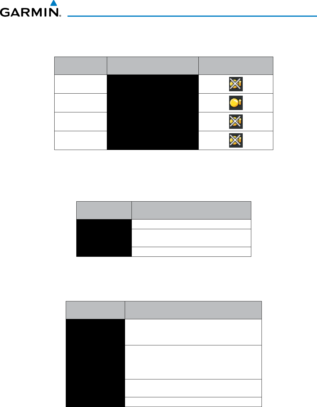
190-00928-04 Rev. A
Garmin G1000 Pilot’s Guide for the Beechcraft 200/B200 Series
457
HAZARD AVOIDANCE
SYSTEM STATUS
The traffic mode is annunciated in the upper left corner of the Traffic Map Page.
Mode Traffic Mode Annunciation
(Traffic Map Page)
Traffic Display Status Icon
(Other Maps)
Traffic System Test
Initiated
TEST
(also shown in white in center of page)
Operating OPERATING
Standby STANDBY
(also shown in white in center of page)
Traffic System Failed* FAIL
* See Table 6-33 for additional failure annunciations
Table 6-32 Traffic Modes
If the traffic unit fails, an annunciation as to the cause of the failure is shown in the center of the Traffic Map
Page. During a failure condition, the Operating Mode cannot be selected.
Traffic Map Page
Annunciation Description
NO DATA Data is not being received from the traffic unit
DATA FAILED Data is being received from the traffic unit, but the
unit is self-reporting a failure
FAILED Incorrect data format received from the traffic unit
Table 6-33 Traffic Failure Annunciations
The annunciations to indicate the status of traffic information appear in a banner at the lower left corner of
maps on which traffic can be displayed.
Traffic Status Banner
Annunciation Description
TA OFF SCALE
A Traffic Advisory is outside the selected display range*.
Annunciation is removed when traffic comes within the
selected display range.
TA X.X ± XX ↕
System cannot determine bearing of Traffic Advisory**.
Annunciation indicates distance in nm, altitude separation
in hundreds of feet, and altitude trend arrow (climbing/
descending).
TRFC FAIL Traffic unit has failed (unit is self-reporting a failure or
sending incorrectly formatted data)
NO TRFC DATA Data is not being received from the traffic unit
*Shown as symbol on Traffic Map Page
**Shown in center of Traffic Map Page
Table 6-34 Traffic Status Annunciations
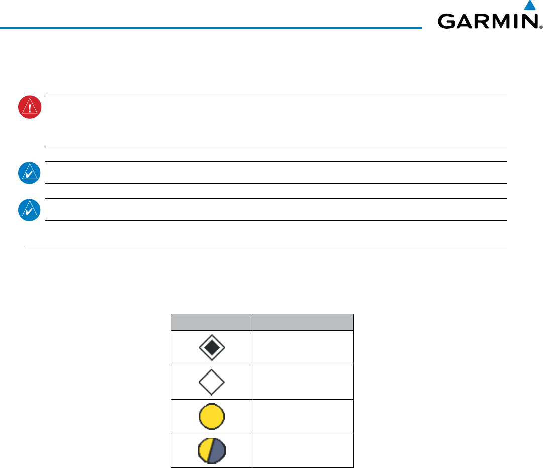
Garmin G1000 Pilot’s Guide for the Beechcraft 200/B200 Series
190-00928-04 Rev. A458
HAZARD AVOIDANCE
6.10 L-3 SKYWATCH TRAFFIC
WARNING: Do not rely solely upon the display of traffic information to accurately depict all of the traffic
information within range of the aircraft. Due to lack of equipment, poor signal reception, and/or inaccurate
information from other aircraft, traffic may be present but not represented on the displays.
NOTE: TIS is disabled when a TAS or Traffic Collision Avoidance System (TCAS) is installed.
NOTE: Refer to the SKYWATCH
®
(SKY497/SKY899) Pilot’s Guide for a detailed discussion of the TAS.
TAS SYMBOLOGY
The optional Traffic Advisory System (TAS) is designed to help in detection and avoidance of other aircraft. TAS
uses an on-board interrogator-processor and an altitude reporting transponder for the air-to-air traffic data link.
Traffic is displayed using the symbology shown in Table 6-35.
Traffic Symbol Description
Non-Threat Traffic
Proximity Advisory (PA)
Traffic Advisory (TA)
Traffic Advisory Off Scale
Table 6-35 Traffic Symbol Description
A Non-threat Advisory, shown as an open white diamond, indicates that an intruding aircraft is at greater than
±1200 feet relative altitude or the distance is beyond 5 nm.
A Proximity Advisory indicates that the intruding aircraft is within ±1200 feet and is within 5 nm range, but
is still not considered a threat.
A Traffic Advisory (TA) alerts the crew to a potentially hazardous intruding aircraft. Closing rate, distance,
and vertical separation meet TA criteria. A Traffic Advisory that is beyond the selected display range is indicated
by a half TA symbol at the edge of the screen at the relative bearing of the intruder.

190-00928-04 Rev. A
Garmin G1000 Pilot’s Guide for the Beechcraft 200/B200 Series
459
HAZARD AVOIDANCE
OPERATION
The unit must be in operating mode for traffic to be displayed. The ability to switch from standby to operating
mode on the ground is especially useful for scanning the airspace around the airport before takeoff.
Switching from standby mode to operating mode:
1) On the Traffic Page, select the
OPERATE
Softkey or press the MENU Key and turn the small
FMS
knob
to select
Operating Mode.
2) If using the FMS menu, press the ENT Key to place the TAS in the operating mode.
3) To switch to Standby Mode from the Traffic Page, select the STANDBY Softkey.
System Test:
1) Set the range to 2/6 nm to allow for full test pattern display.
2) Select the STANDBY Softkey.
3) Select the TEST Softkey. ‘TEST MODE’ is annunciated on the MFD.
4) Self test takes approximately eight seconds to complete. When completed successfully, traffic symbols display
and a voice alert is heard to indicate the system test passed.
DISPLAYING TRAFFIC DATA
Traffic information can be displayed on the following maps when the unit is operating:
• PFD Inset Map
• Navigation Map Page
• Traffic Map Page
• Trip Planning Page
• Active Flight Plan Page
• Nearest Pages
Traffic information can also be displayed on the PFDs when the Synthetic Vision Technology (SVT) option is
installed and enabled. See the Additional Features Section for details.
Displaying traffic on the Traffic Map Page:
1) Turn the large
FMS
Knob to select the Map Page Group.
2) Turn the small
FMS
Knob
to select the Traffic Map Page.
3) Select the OPERATE Softkey to begin displaying traffic. OPERATING is displayed in the Traffic mode field.
4) Select the ALT MODE Softkey to change the altitude volume.
5) Select the STANDBY Softkey to place the system in the Standby mode. STANDBY is displayed in the Traffic
mode field.
6) Turn the RANGE Knob clockwise to display a larger area or counter-clockwise to display a smaller area.
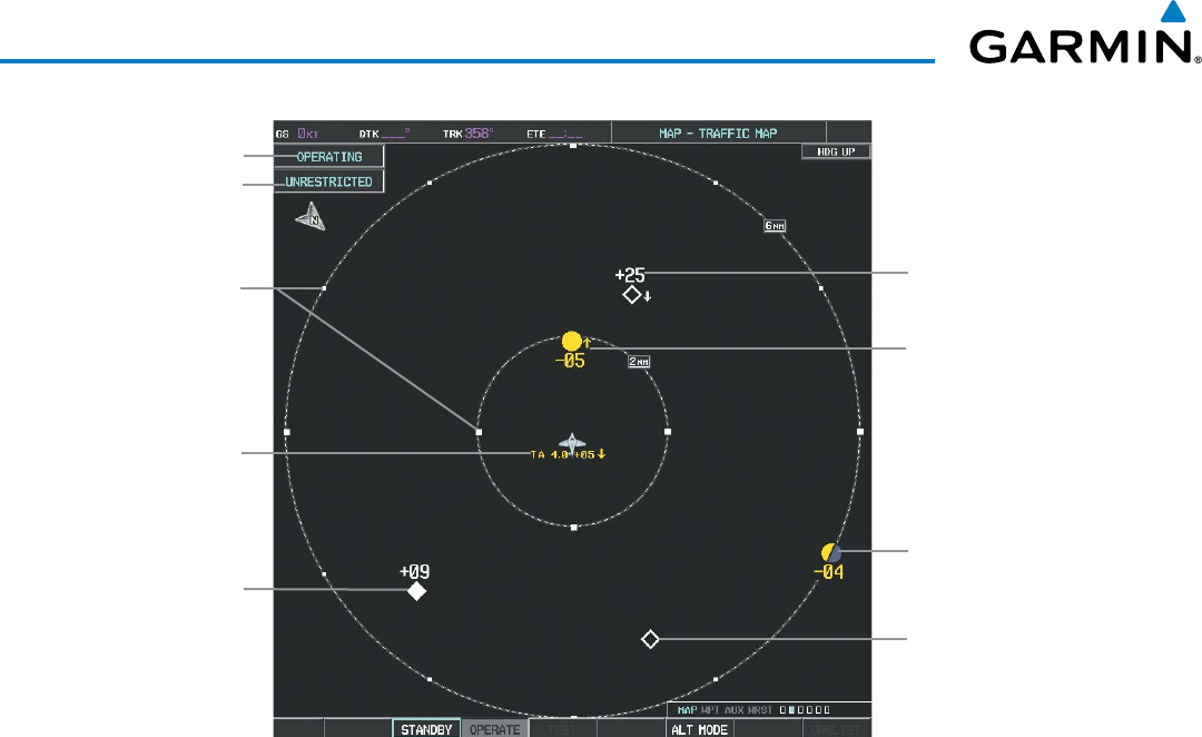
Garmin G1000 Pilot’s Guide for the Beechcraft 200/B200 Series
190-00928-04 Rev. A460
HAZARD AVOIDANCE
Figure 6-177 Traffic Map Page
Operating
Mode
Altitude
Mode
Traffic Advisory,
Aircraft is
500’ Below,
Climbing
Off Scale Traffic
Advisory, 400’
Below, No
Vertical Trend
“No Bearing”
Traffic (Bearing
Undetermined),
Distance 4.0
nm, 500’ Above,
Descending
Proximity
Traffic, 900’
Above, No
Vertical Trend
Traffic Display
Range Rings
Non-Threat
Traffic, 2500’
Above,
Descending
Non-Threat Traffic,
Altitude Not
Reported
The Map - Traffic Map Page shows surrounding TAS traffic data in relation to the aircraft’s current position
and altitude, without basemap clutter. It is the principal map page for viewing traffic information. Aircraft
orientation is always heading up unless there is no valid heading. Map range is adjustable with the RANGE
Knob, as indicated by the map range rings.
The traffic mode and altitude display mode are annunciated in the upper left corner.
Displaying traffic information (maps other than the Traffic Map Page):
1) Select the MAP Softkey.
2) Select the TRAFFIC Softkey. Traffic is now displayed on the map.
When traffic is selected on maps other than the Traffic Map Page, a traffic icon is shown to indicate TAS is
enabled for display.
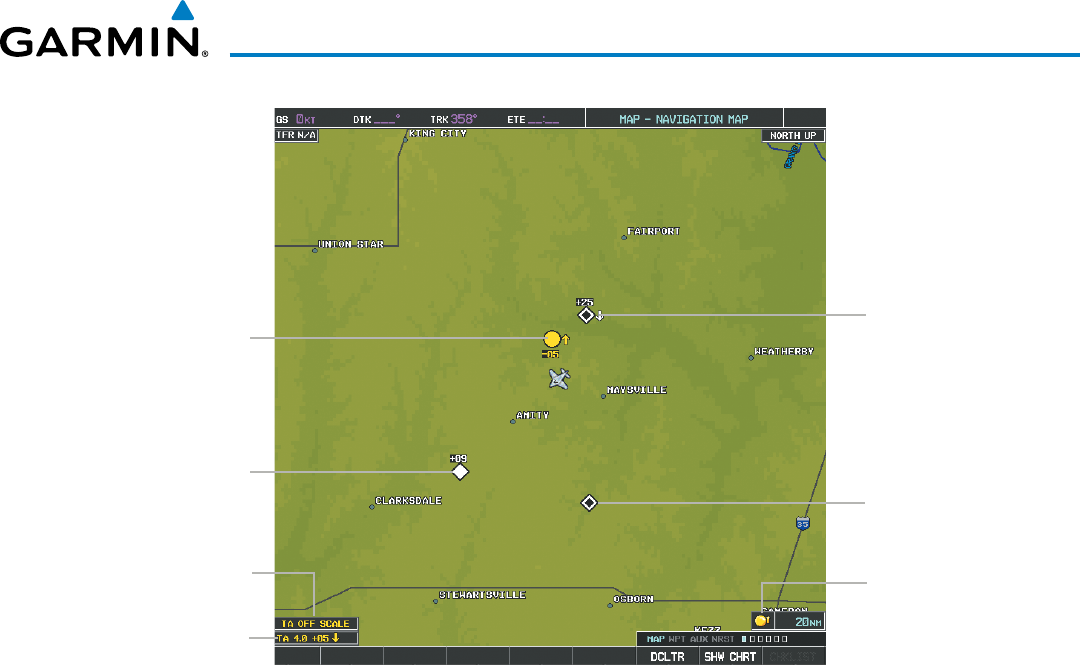
190-00928-04 Rev. A
Garmin G1000 Pilot’s Guide for the Beechcraft 200/B200 Series
461
HAZARD AVOIDANCE
Figure 6-178 TAS Traffic on the Navigation Map Page
“Non-Bearing”
Traffic Advisory
Traffic Advisory
Off-Scale
Non-Threat
Traffic, 2500’
Above,
Descending
Traffic Advisory,
500’ Below,
Climbing
Proximity Traffic,
900’ Above,
Level Non-Threat
Traffic, Altitude
Not Available
Traffic Display
Enabled Icon
Displaying traffic information (PFD Inset Map):
1) Select the INSET Softkey.
2) Select the TRAFFIC Softkey to display traffic data on the inset map (TRFC-1).
3) Select the softkey again to display the traffic-only inset (TRFC-2).
4) Select the softkey again to remove traffic data.
The Navigation Map Page Setup Menu also controls the display of traffic. The setup menu controls the map
range settings. Traffic data symbols and labels can be decluttered from the display. If a map range larger than
the map range setting is selected, the data is removed from the map. Maps besides the Traffic Map Page use
settings based on those selected for the Navigation Map Page.

Garmin G1000 Pilot’s Guide for the Beechcraft 200/B200 Series
190-00928-04 Rev. A462
HAZARD AVOIDANCE
ALTITUDE DISPLAY
Changing the altitude display mode:
1) On the Traffic Page, select the
ALT MODE
Softkey.
2) Select one of the following Softkeys:
• BELOW
• NORMAL
• ABOVE
• UNREST (unrestricted)
3) To return to the Traffic Page, select the BACK Softkey.
Or:
1) Press the MENU Key.
2) Turn the small
FMS
Knob
to select one of the following:
• BELOW
• NORMAL
• ABOVE
• UNREST (unrestricted)
3) Press the ENT Softkey.
TRAFFIC MAP PAGE DISPLAY RANGE
The display range on the Traffic Map Page can be changed at any time. Map range is adjustable with the
RANGE Knob from 2 to 40 nm, as indicated by the map range rings.
Changing the display range on the Traffic Page:
1) Turn the RANGE Knob.
2) The following range options are available:
• 2 nm
• 2 and 6 nm
• 6 and 12 nm
• 12 and 24 nm*
• 24 and 40 nm*
* Range available only on the SKY899 TAS.
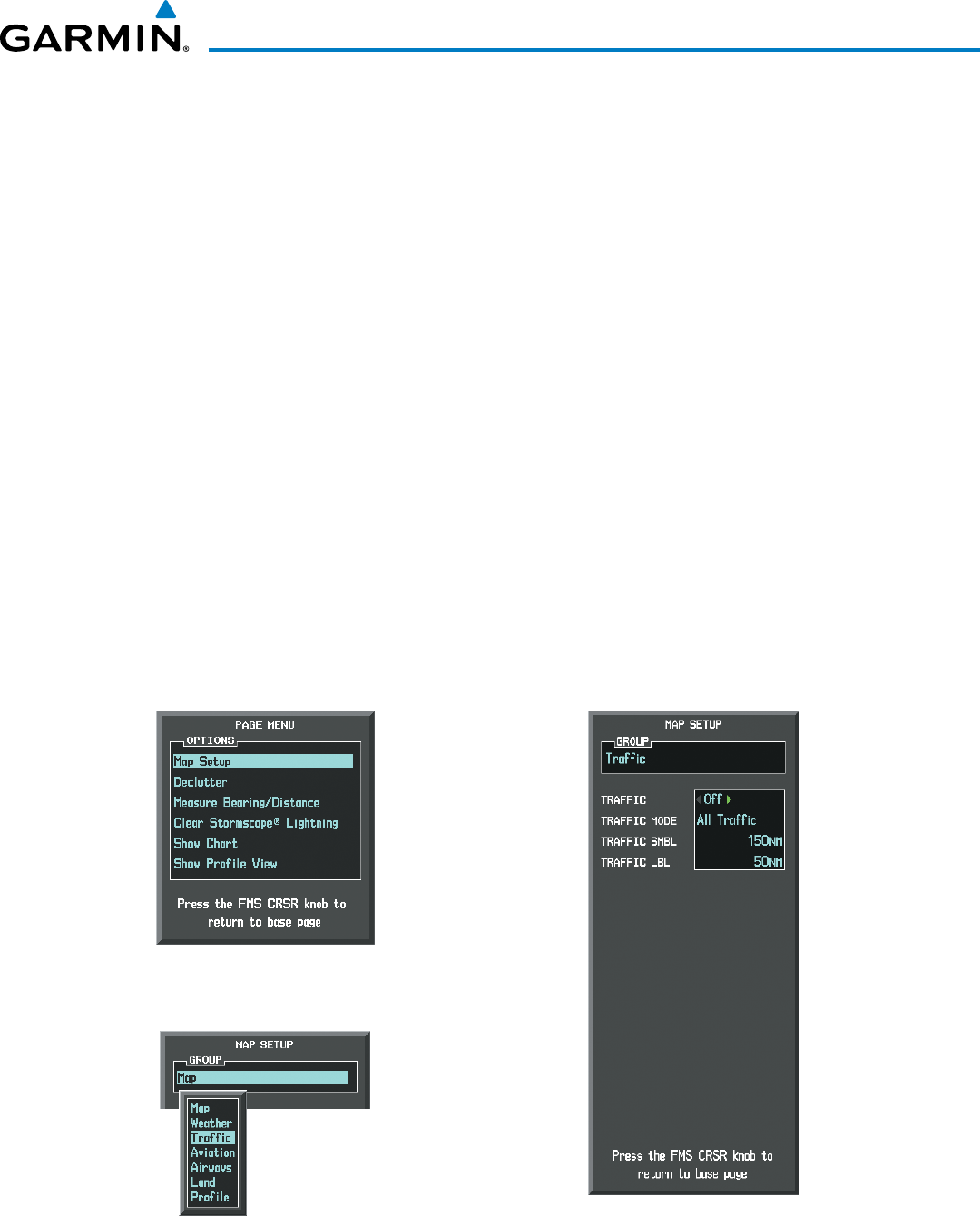
190-00928-04 Rev. A
Garmin G1000 Pilot’s Guide for the Beechcraft 200/B200 Series
463
HAZARD AVOIDANCE
Customizing the traffic display on the Navigation Map Page:
1) Select the Navigation Map Page.
2) Press the MENU Key.
3) With Map Setup highlighted, press the
ENT
Key (Figure 6-179).
4) Turn the small FMS Knob to select the Traffic Group and press the ENT Key (Figure 6-180).
5) Turn the large
FMS
Knob or press the
ENT
Key to scroll through the selections (Figure 6-181).
• TRAFFIC – Turns the display of traffic data on or off
• TRAFFIC MODE – Selects the traffic mode for display; select from:
- All Traffic - Displays all traffic
- TA/PA - Displays Traffic Alerts and Proximity Advisories
- TA ONLY - Displays Traffic Alerts only
• TRAFFIC SMBL – Selects the maximum range at which traffic symbols are shown
• TRAFFIC LBL – Selects the maximum range at which traffic labels are shown with the option to turn off
6) Turn the small
FMS
Knob to scroll through options (ON/OFF, range settings, etc.).
7) Press the
ENT
Key to select an option.
8) Press the FMS Knob or CLR Key to return to the Navigation Map Page.
Figure 6-180 Navigation Map Page Setup Menu
Figure 6-179 Navigation Map Page Menu
Figure 6-181 Navigation Map Page Setup Menu, Traffic Group
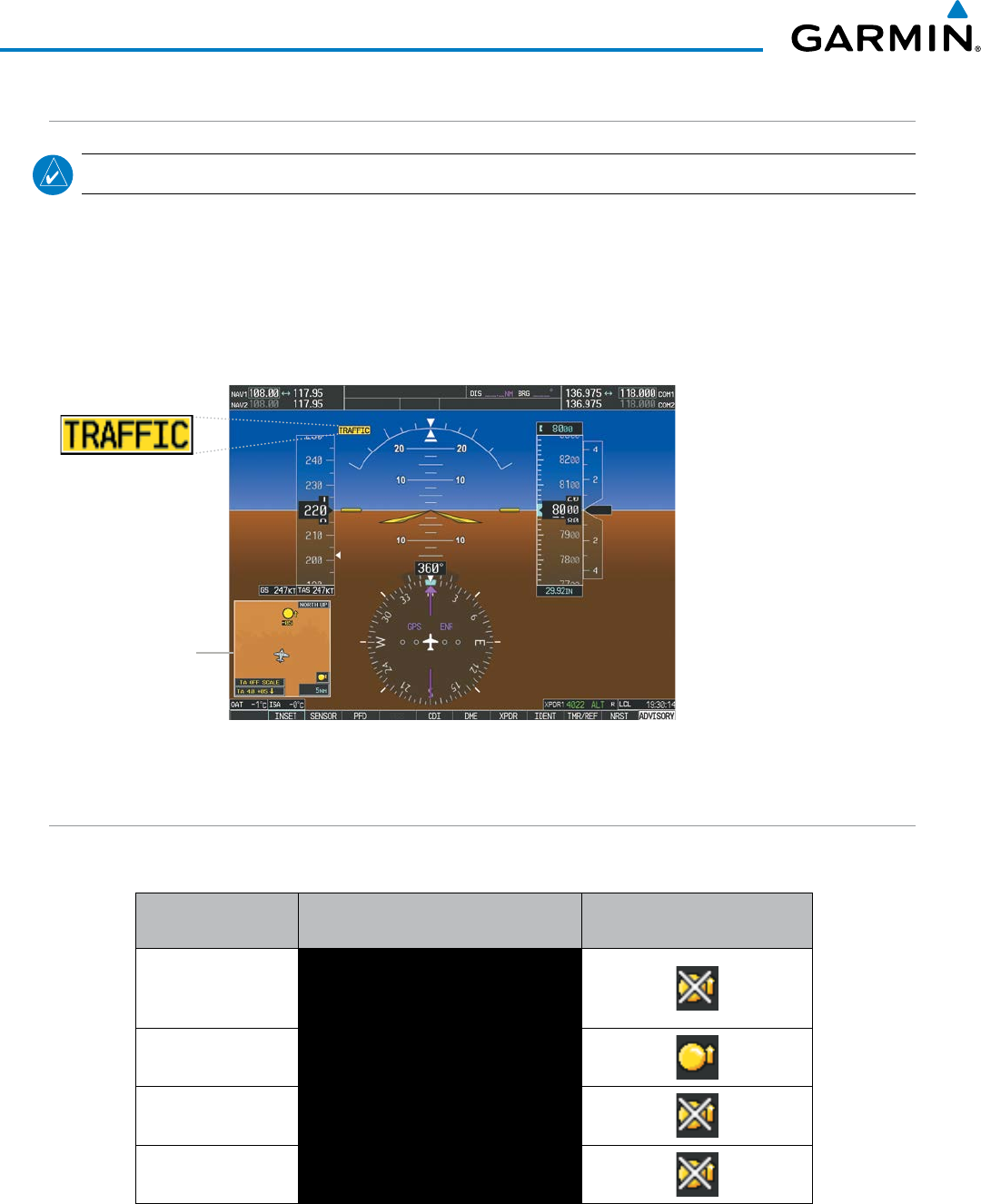
Garmin G1000 Pilot’s Guide for the Beechcraft 200/B200 Series
190-00928-04 Rev. A464
HAZARD AVOIDANCE
TAS ALERTS
NOTE: Refer to the TAS documentation for information on alerts generated by the TAS equipment.
When the number of TAs on the Traffic Map Page increases from one scan to the next, the following occur:
• A “Traffic, Traffic” voice alert is generated.
• A TRAFFIC Annunciation appears at the top right of the airspeed on the PFD, flashing for 5 seconds and
remaining displayed until no TAs are detected in the area.
• The PFD Inset Map is automatically displayed with TA traffic
Figure 6-182 Traffic Annunciation (PFD)
Inset Map
Displays When
TA is Detected
SYSTEM STATUS
The traffic mode is annunciated in the upper left corner of the Traffic Map Page.
Mode Traffic Mode Annunciation
(Traffic Map Page)
Traffic Display Status Icon
(Other Maps)
TAS Self-test Initiated
TEST
(‘TEST MODE’ also shown in white on
top center of page)
TAS Operating OPERATING
TAS Standby STANDBY
(also shown in white in center of page)
TAS Failed* FAIL
* See Table 6-37 for additional failure annunciations
Table 6-36 TAS Modes
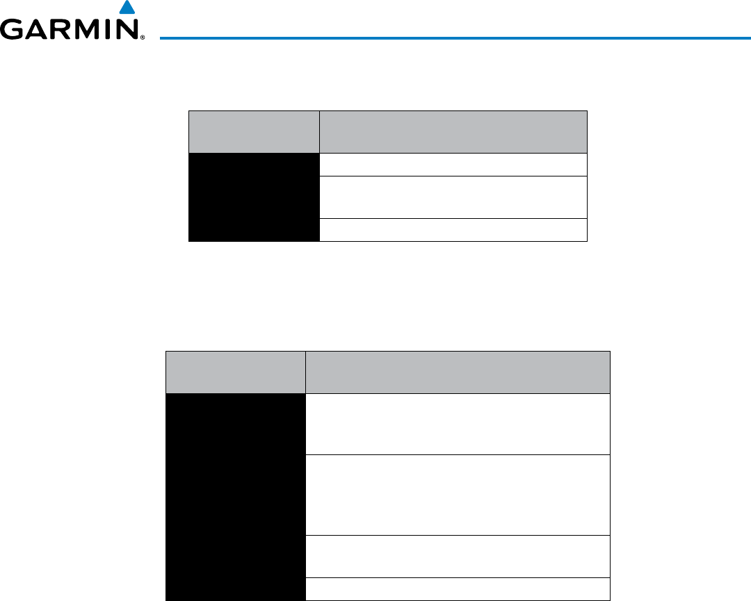
190-00928-04 Rev. A
Garmin G1000 Pilot’s Guide for the Beechcraft 200/B200 Series
465
HAZARD AVOIDANCE
If the unit fails, an annunciation as to the cause of the failure is shown in the center of the Traffic Map Page.
Traffic Map Page
Annunciation Description
NO DATA Data is not being received from the TAS unit
DATA FAILED Data is being received from the TAS unit, but the
unit is self-reporting a failure
FAILED Incorrect data format received from the TAS unit
Table 6-37 TAS Failure Annunciations
The annunciations to indicate the status of traffic information appear in a banner at the lower left corner of
maps on which traffic can be displayed.
Traffic Status Banner
Annunciation Description
TA OFF SCALE
A Traffic Advisory is outside the selected display range*
Annunciation is removed when traffic comes within the
selected display range
TA X.X ± XX ↕
System cannot determine bearing of Traffic Advisory**
Annunciation indicates distance in nm, altitude
separation in hundreds of feet, and altitude trend arrow
(climbing/descending)
TRFC FAIL TAS unit has failed (unit is self-reporting a failure or
sending incorrectly formatted data)
NO TRFC DATA Data is not being received from the TAS unit
*Shown as symbol on Traffic Map Page
**Shown in center of Traffic Map Page
Table 6-38 TAS Traffic Status Annunciations
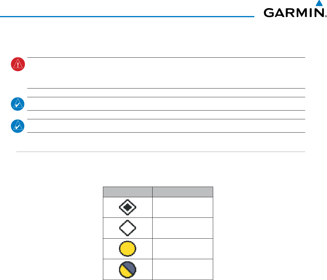
Garmin G1000 Pilot’s Guide for the Beechcraft 200/B200 Series
190-00928-04 Rev. A466
HAZARD AVOIDANCE
6.11 HONEYWELL KTA 870 TRAFFIC
WARNING: Do not rely solely upon the display of traffic information to accurately depict all of the traffic
information within range of the aircraft. Due to lack of equipment, poor signal reception, and/or inaccurate
information from other aircraft, traffic may be present but not represented on the displays.
NOTE: TIS is disabled when a TAS is installed.
NOTE: Refer to the Honeywell® KTA 870 Pilot’s Guide for a detailed discussion of the KTA 870 TAS.
TAS SYMBOLOGY
The optional Honeywell KTA 870 Traffic Advisory System (TAS) is designed to help in detection and avoidance
of other aircraft. TAS uses an on-board interrogator-processor and the Mode S transponder for the air-to-air traffic
data link. Traffic is displayed using four different symbols.
TAS Symbol Description
Non-Threat Traffic
Proximity Advisory (PA)
Traffic Advisory (TA)
Traffic Advisory Off Scale
Table 6-39 TAS Symbol Description
A Non-threat Advisory, shown as an open white diamond, indicates that an intruding aircraft is at greater than
±1200 feet relative altitude or the distance is beyond 5 nm.
A Proximity Advisory indicates that the intruding aircraft is within ±1200 feet and is within 5 nm range, but
is still not considered a threat.
A Traffic Advisory (TA) alerts the crew to a potentially hazardous intruding aircraft. Closing rate, distance,
and vertical separation meet TA criteria. A Traffic Advisory that is beyond the selected display range is indicated
by a half TA symbol at the edge of the screen at the relative bearing of the intruder.

190-00928-04 Rev. A
Garmin G1000 Pilot’s Guide for the Beechcraft 200/B200 Series
467
HAZARD AVOIDANCE
OPERATION
The KTA 870 must be in Operating Mode for traffic to be displayed. The unit starts in Operating Mode upon
power-up.
Selecting the STANDBY Softkey forces the unit into Standby Mode. Selecting the NORMAL Softkey allows
the KTA 870 to switch from Standby Mode to Operating Mode as necessary.
Switching from operating mode to standby mode:
On the Traffic Page, select the
STANDBY
Softkey
Or:
1) Press the MENU Key and turn the small
FMS
knob
to select Standby Mode.
2) Press the ENT Key.
Switching from standby mode to operating mode:
On the Traffic Page, select the
NORMAL
Softkey
Or:
1) Press the MENU Key and turn the small
FMS
knob
to select Normal Mode.
2) Press the ENT Key. The KTA 870 switches from Standby Mode to Operating Mode as necessary.
System Self Test
1) Set the range to 2/6 nm to allow for full test pattern display.
2) Select the TEST Softkey.
3) Self test takes approximately eight seconds to complete. When completed successfully, traffic symbols are
displayed and a voice alert “TAS System Test OK” is heard. In the event that the system test fails, the
system reverts to Standby Mode and a voice alert “TAS System Test Fail” is heard.
Displaying traffic on the Traffic Map Page:
1) Turn the large
FMS
Knob to select the Map Page Group.
2) Turn the small
FMS
Knob
to select the Traffic Map Page.
3) Select the NORMAL Softkey to begin displaying traffic. OPERATING is displayed in the Traffic mode field.
4) Select the ALT MODE Softkey to change the altitude volume.
5) Select the STANDBY Softkey to place the system in the Standby mode. STANDBY is displayed in the Traffic
mode field.
6) Turn the RANGE Knob clockwise to display a larger area or counter-clockwise to display a smaller area.
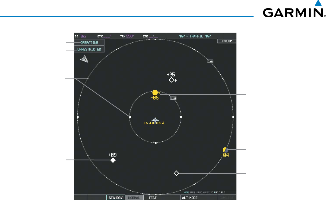
Garmin G1000 Pilot’s Guide for the Beechcraft 200/B200 Series
190-00928-04 Rev. A468
HAZARD AVOIDANCE
Figure 6-183 Traffic Map Page
Operating
Mode
Altitude
Mode
Traffic Advisory,
Aircraft is
500’ Below,
Climbing
Off Scale Traffic
Advisory, 400’
Below, No
Vertical Trend
“No Bearing”
Traffic (Bearing
Undetermined),
Distance 4.0
nm, 500’ Above,
Descending
Proximity
Traffic, 900’
Above, No
Vertical Trend
Traffic Display
Range Rings
Non-Threat
Traffic, 2500’
Above,
Descending
Non-Threat Traffic,
Altitude Not
Reported
The Map - Traffic Map Page shows surrounding TAS traffic data in relation to the aircraft’s current position
and altitude, without basemap clutter. It is the principal map page for viewing traffic information. Aircraft
orientation is always heading up unless there is no valid heading. Map range is adjustable with the RANGE
Knob from 2 to 40 nm, as indicated by the map range rings.
The traffic mode and altitude display mode are annunciated in the upper left corner.
DISPLAYING TRAFFIC DATA
Traffic information can be displayed on the following maps when the KTA 870 unit is operating:
• PFD Inset Map
• Navigation Map Page
• Traffic Map Page
• Trip Planning Page
• Nearest Pages
• Active Flight Plan Page
Displaying traffic information (maps other than the Traffic Map Page):
1) Select the MAP Softkey.
2) Select the TRAFFIC Softkey. Traffic is now displayed on the map.
When traffic is selected on maps other than the Traffic Map Page, a traffic icon is shown to indicate the
traffic system is enabled for display.
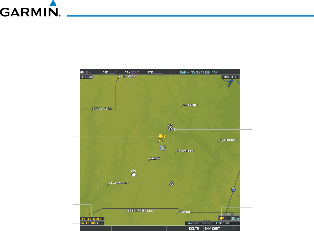
190-00928-04 Rev. A
Garmin G1000 Pilot’s Guide for the Beechcraft 200/B200 Series
469
HAZARD AVOIDANCE
Displaying traffic on the Navigation Map
1) Ensure the TAS system is operating. With the Navigation Map displayed, select the
MAP
Softkey.
2) Select the
TRAFFIC
Softkey. Traffic is now displayed on the map as shown in the figure.
Figure 6-184 TAS Traffic on the Navigation Map Page
“Non-Bearing”
Traffic Advisory
Traffic Advisory
Off-Scale
Non-Threat
Traffic, 2500’
Above,
Descending
Traffic Advisory,
500’ Below,
Climbing
Proximity Traffic,
900’ Above,
Level Non-Threat
Traffic, Altitude
Not Available
Traffic Display
Enabled Icon
Displaying traffic information (PFD Inset Map):
1) Select the INSET Softkey.
2) Select the TRAFFIC Softkey to display traffic data on the inset map (TRFC-1).
3) Select the softkey again to display the traffic-only inset (TRFC-2).
4) Select the softkey again to remove traffic data.

Garmin G1000 Pilot’s Guide for the Beechcraft 200/B200 Series
190-00928-04 Rev. A470
HAZARD AVOIDANCE
ALTITUDE DISPLAY
The flight crew can select the volume of airspace for which traffic is displayed. Traffic Advisories (TAs)
outside of these limits will still be shown. Refer to the KTA 870 Pilot’s Guide for specific display thresholds.
Changing the altitude display mode:
1) On the Traffic Page, select the
ALT MODE
Softkey.
2) Select one of the following Softkeys:
• BELOW
• NORMAL
• ABOVE
• UNREST (unrestricted)
3) To return to the Traffic Page, select the BACK Softkey.
Or:
1) Press the MENU Key.
2) Turn the small
FMS
Knob
to select one of the following:
• BELOW
• NORMAL
• ABOVE
• UNREST (unrestricted)
3) Select the ENT Softkey.
TRAFFIC MAP PAGE DISPLAY RANGE
The display range on the Traffic Map Page can be changed at any time. Map range is adjustable with the
RANGE Knob from 2 to 40 nm, as indicated by the map range rings.
Changing the display range on the Traffic Page:
1) Turn the RANGE Knob.
2) The following range options are available:
• 2 nm
• 2 and 6 nm
• 6 and 12 nm
• 12 and 24 nm
• 24 and 40 nm
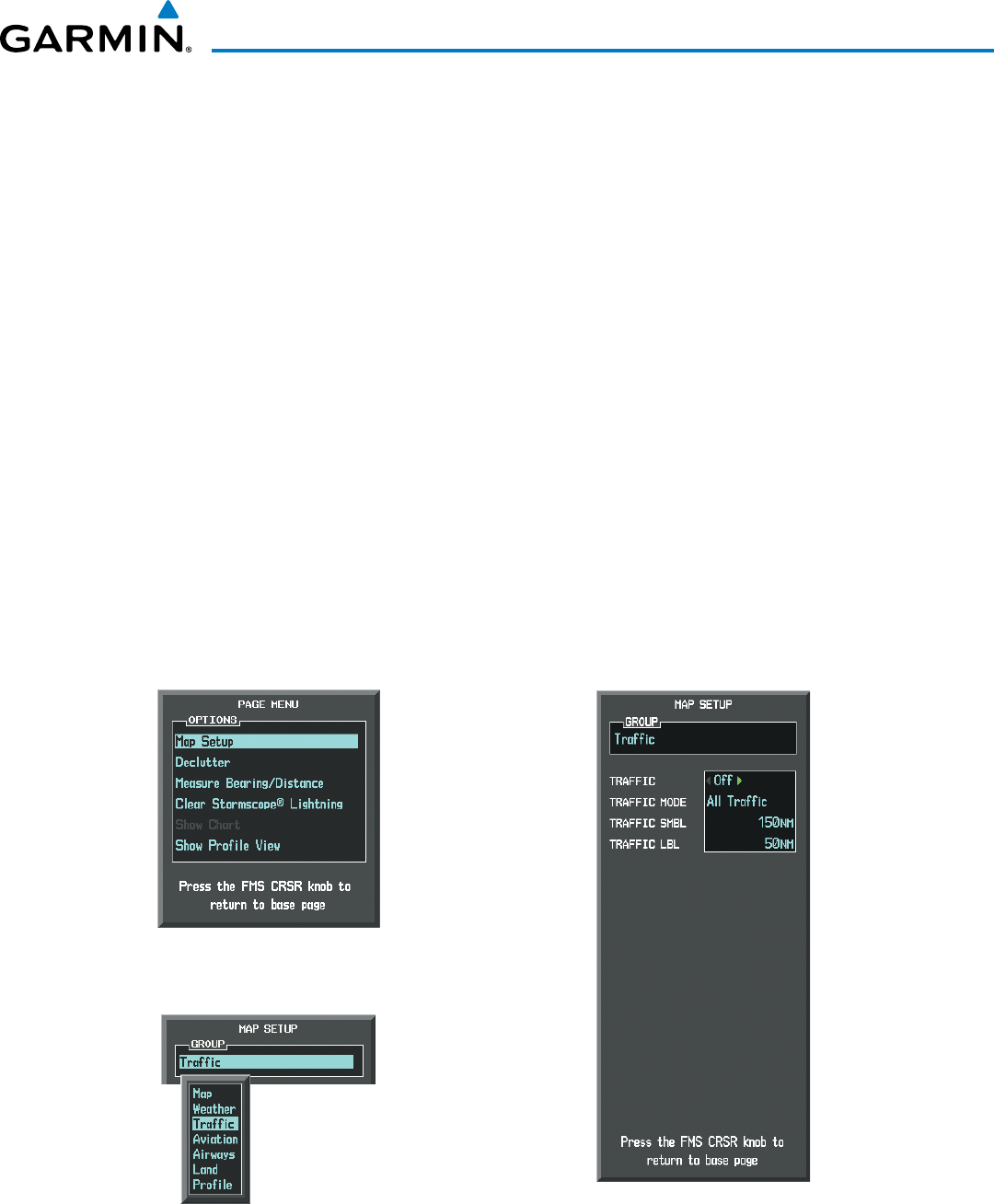
190-00928-04 Rev. A
Garmin G1000 Pilot’s Guide for the Beechcraft 200/B200 Series
471
HAZARD AVOIDANCE
Customizing the traffic display on the Navigation Map Page:
1) Select the Navigation Map Page.
2) Press the MENU Key.
3) With Map Setup highlighted, press the
ENT
Key (Figure 6-185).
4) Turn the small FMS Knob to select the Traffic Group and press the ENT Key (Figure 6-186).
5) Turn the large
FMS
Knob or press the
ENT
Key to scroll through the selections (Figure 6-187).
• TRAFFIC – Turns the display of traffic data on or off
• TRAFFIC MODE – Selects the traffic mode for display; select from:
- All Traffic - Displays all traffic
- TA/PA - Displays Traffic Alerts and Proximity Advisories
- TA ONLY - Displays Traffic Alerts only
• TRAFFIC SMBL – Selects the maximum range at which traffic symbols are shown
• TRAFFIC LBL – Selects the maximum range at which traffic labels are shown with the option to turn off
6) Turn the small
FMS
Knob to scroll through options (ON/OFF, range settings, etc.).
7) Press the
ENT
Key to select an option.
8) Press the FMS Knob or CLR Key to return to the Navigation Map Page.
Figure 6-186 Navigation Map Page Setup Menu
Figure 6-185 Navigation Map Page Menu
Figure 6-187 Navigation Map Page Setup Menu, Traffic Group
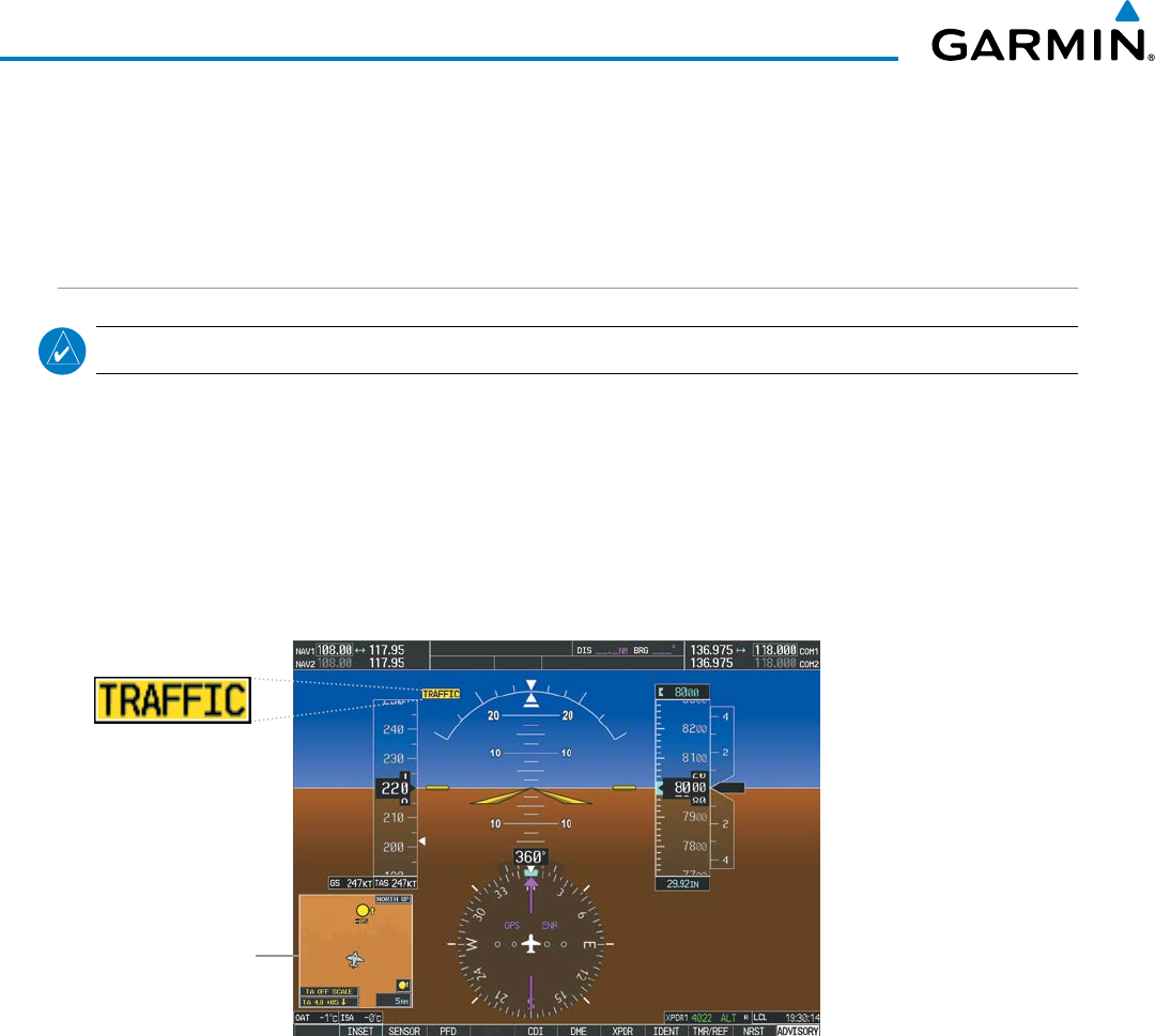
Garmin G1000 Pilot’s Guide for the Beechcraft 200/B200 Series
190-00928-04 Rev. A472
HAZARD AVOIDANCE
The Navigation Map Page Setup Menu also controls the display of traffic. The setup menu controls the map
range settings. Traffic data symbols and labels can be decluttered from the display. If a map range larger than
the map range setting is selected, the data is removed from the map. Maps besides the Traffic Map Page use
settings based on those selected for the Navigation Map Page.
TAS ALERTS
NOTE: Refer to the KTA 870 documentation for information on alerts generated by the TAS equipment.
When the number of TAs on the Traffic Map Page increases from one scan to the next, the following occur:
• A “Traffic, Traffic” voice alert is generated when the first TA is displayed.
• A TRAFFIC Annunciation appears at the top right of the airspeed on the PFD, flashing for 5 seconds and
remaining displayed until no TAs are detected in the area.
• The PFD Inset Map is automatically displayed with TA traffic.
• A single “Traffic” voice alert is generated when the number of TAs increases.
Figure 6-188 Traffic Annunciation (PFD)
Inset Map
Displays When
TA is Detected
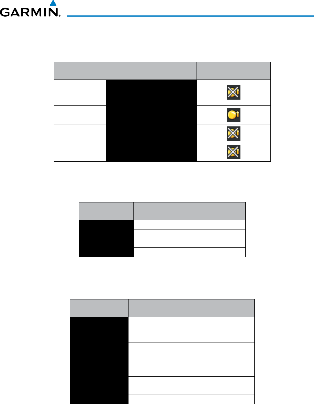
190-00928-04 Rev. A
Garmin G1000 Pilot’s Guide for the Beechcraft 200/B200 Series
473
HAZARD AVOIDANCE
SYSTEM STATUS
The traffic mode is annunciated in the upper left corner of the Traffic Map Page.
Mode Traffic Mode Annunciation
(Traffic Map Page)
Traffic Display Status Icon
(Other Maps)
TAS Self-test Initiated
TEST
(‘TEST MODE’ also shown in white on
top center of page)
TAS Operating OPERATING
TAS Standby STANDBY
(also shown in white in center of page)
TAS Failed* FAIL
* See Table 6-41 for additional failure annunciations
Table 6-40 TAS Modes
If the unit fails, an annunciation as to the cause of the failure is shown in the center of the Traffic Map Page.
Traffic Map Page
Annunciation Description
NO DATA Data is not being received from the TAS unit
DATA FAILED Data is being received from the TAS unit, but the
unit is self-reporting a failure
FAILED Incorrect data format received from the TAS unit
Table 6-41 TAS Failure Annunciations
The annunciations to indicate the status of traffic information appear in a banner at the lower left corner of
maps on which traffic can be displayed.
Traffic Status Banner
Annunciation Description
TA OFF SCALE
A Traffic Advisory is outside the selected display range*
Annunciation is removed when traffic comes within the
selected display range
TA X.X ± XX ↕
System cannot determine bearing of Traffic Advisory**
Annunciation indicates distance in nm, altitude
separation in hundreds of feet, and altitude trend
arrow (climbing/descending)
TRFC FAIL TAS unit has failed (unit is self-reporting a failure or
sending incorrectly formatted data)
NO TRFC DATA Data is not being received from the TAS unit
*Shown as symbol on Traffic Map Page
**Shown in center of Traffic Map Page
Table 6-42 TAS Traffic Status Annunciations
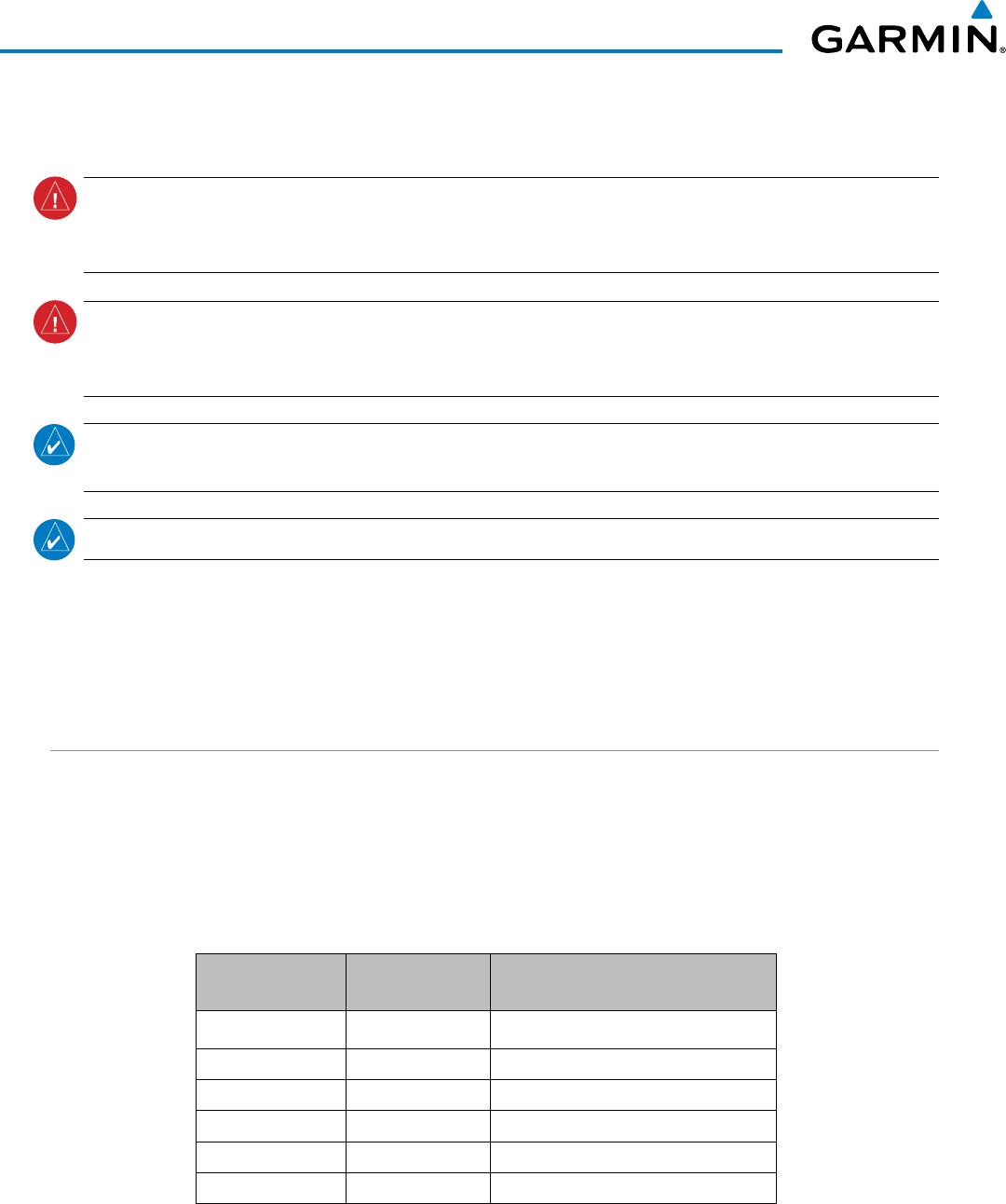
Garmin G1000 Pilot’s Guide for the Beechcraft 200/B200 Series
190-00928-04 Rev. A474
HAZARD AVOIDANCE
6.12 GTS 8000 TCAS II TRAFFIC
WARNING:
Traffic information shown on system displays is provided as an aid in visually acquiring
traffic. Traffic avoidance maneuvers are based upon TCAS II Resolution Advisories , ATC guidance, or
positive visual acquisition of conflicting traffic.
WARNING: Do not rely solely upon the display of traffic information to accurately depict all of the traffic
information within range of the aircraft. Due to lack of equipment, poor signal reception, and/or inaccurate
information from other aircraft, traffic may be present but not represented on the displays.
NOTE: If the installed TCAS II traffic system is not a Garmin GTS 8000, refer to the applicable documentation
for system-specific information.
NOTE: TIS is disabled when TCAS II is installed.
A Traffic Alert and Collision Avoidance System II (TCAS II), such as the Garmin GTS 8000, improves flight
safety by monitoring the airspace for other aircraft with operating transponders in the vicinity. The TCAS II
system provides traffic information to the displays, and if separation from other aircraft is within certain limits,
the system issues Traffic Advisories (TAs) to assist the flight crew in the visual acquisition of traffic, or Resolution
Advisories (RAs) to provide recommended vertical guidance to resolve a traffic conflict.
THEORY OF OPERATION
When the TCAS II system is operating in TA/RA or TA Only Mode, the system interrogates the transponders
of other aircraft in the vicinity, and monitors for replies from these transponders. Based on successive replies,
the system tracks the range, bearing, and if reported, the altitudes of other aircraft. For each detected aircraft
transponder, the system calculates the time to, and separation at, the closest point of approach (CPA) around
potential collision area surrounding own aircraft. Based on this time, the own aircraft altitude, and the selected
TCAS II system mode, the system determines if a TA or RA should be issued for the detected intruder traffic.
Altitude in Feet* TA Time to CPA
in Seconds RA Time to CPA in Seconds
Up to 1000 20 RA not issued below 1000’ AGL
1000-2350 25 15
2350-5000 30 20
5000-10000 40 25
10000-20000 45 30
20000 and above 48 35
* System uses pressure altitude except when Radar Altimeter altitude is displayed on the
PFDs, in which case Radar Altitude takes precedence.
Table 6-43 Altitude-based TCAS II TA and RA Alert Thresholds
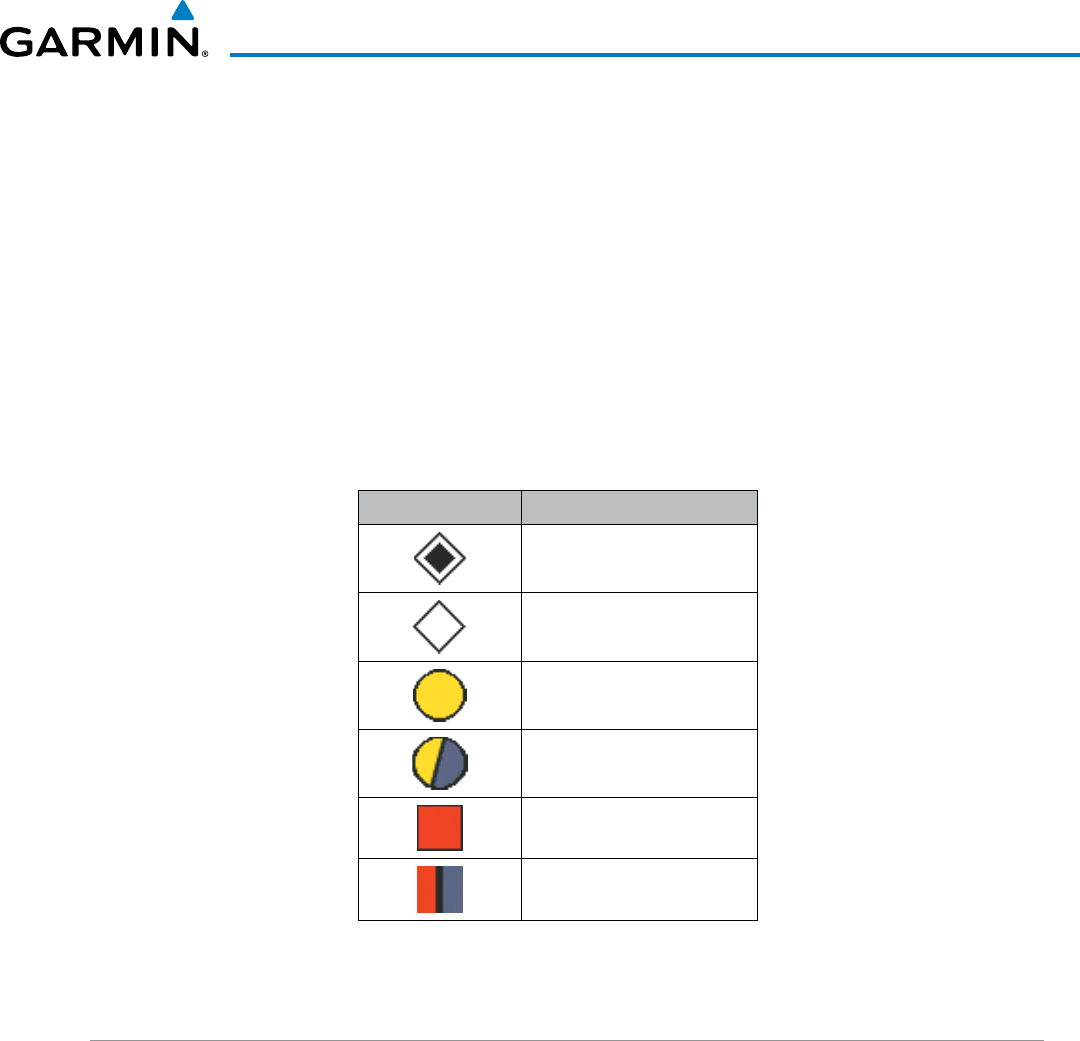
190-00928-04 Rev. A
Garmin G1000 Pilot’s Guide for the Beechcraft 200/B200 Series
475
HAZARD AVOIDANCE
The TCAS II system categorizes detected traffic into four groups of increasing threat potential:
• Other, Non-Threat Traffic, displayed as a hollow white diamond, is not currently a threat.
• Proximity Advisory (PA) Traffic, displayed as a filled white diamond, is not currently a threat, but is within
six nm and ±1200 feet of own-aircraft altitude.
• Traffic Advisory (TA), displayed as a filled yellow circle, indicates traffic is within 20-48 seconds of a potential
collision area. If a Traffic Map is shown, and the TA traffic is beyond the selected map range, the system
displays a half-TA symbol at the edge of the map at the approximate relative bearing of the TA traffic. If TA
traffic subsequently meets the criteria for an RA, the system will issue an RA.
• Resolution Advisory (RA), displayed as a filled red square, indicates traffic is within 15-35 seconds of a
potential collision area. If a Traffic Map is shown, and the RA traffic is beyond the selected map range, the
system displays a half-RA symbol at the edge of the map at the approximate relative bearing of the RA traffic.
Traffic Symbol Description
Other, Non-Threat Traffic
Proximity Advisory (PA)
Traffic Advisory (TA)
Traffic Advisory Off Scale
Resolution Advisory (RA)
Resolution Advisory Off Scale
Table 6-44 TCAS II Traffic Symbol Description
TCAS II ALERTS
When the TCAS II unit issues a TA or RA, the following occur:
• The TCAS II system issues a voice alert.
• A ‘TRAFFIC’ annunciation appears at the top right of the airspeed indicator on the PFD, flashes for 5 seconds
and remains displayed until no TAs or RAs are detected in the area. RA TRAFFIC annunciations are white
text with red backgrounds; TA ‘TRAFFIC’ annunciations are black text with yellow backgrounds. If a TA and
RA occur simultaneously, only the red and white RA ‘TRAFFIC’ annunciation is shown.
• The PFD Inset Traffic Map displays TA or RA traffic.
• During an RA only, voice alert(s) provide vertical guidance to resolve the traffic conflict. The Vertical Speed
Indicator displays a range of vertical speeds to fly to or avoid as applicable (Figure 6-189). Additional voice
alerts may occur to denote changes in the RA status, as necessary.
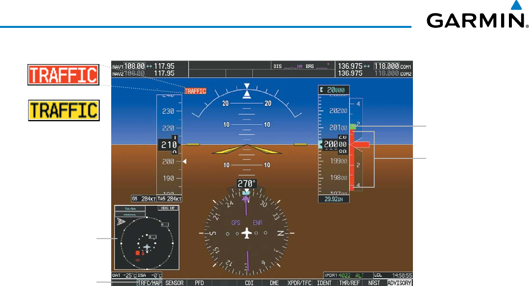
Garmin G1000 Pilot’s Guide for the Beechcraft 200/B200 Series
190-00928-04 Rev. A476
HAZARD AVOIDANCE
Softkey Displays/
Removes Inset
Traffic Map
Inset Traffic Map
Displays When TA
or RA is Detected
No-Fly Vertical
Speed Range
Fly-To Vertical
Speed Range
Figure 6-189 Traffic Annunciation with Resolution Advisory (PFD)
RA Annunciation
TA Annunciation
RESOLUTION ADVISORIES
Resolution Advisories (RAs) include recommended vertical guidance maneuvers to be flown in order to
resolve a traffic conflict. If other aircraft involved in the RA encounter are also equipped with a TCAS II
system, the systems coordinate the recommended maneuvers using the Mode S data link in order to produce
complimentary responses to resolve the RA. While an RA is occurring, the system monitors the status, and if
necessary, strengthens, weakens, reverses the RA, or declares the aircraft is clear of the traffic conflict.
RAs are categorized into the preventative and corrective types.
PReventative RaS
The system issues a Preventative RA to indicate the present vertical speed will resolve the traffic conflict.
The system indicates a range of vertical speeds to be avoided, indicated by one or more red bands inside the
VSI. The current vertical speed is outside of the avoidance area during a Preventative RA.

190-00928-04 Rev. A
Garmin G1000 Pilot’s Guide for the Beechcraft 200/B200 Series
477
HAZARD AVOIDANCE
Preventative RA Type Required Vertical Speed
(fpm)
Do Not Climb < 0
Do Not Climb > 500 fpm < 500
Do Not Climb > 1000 fpm < 1000
Do Not Climb > 2000 fpm < 2000
Do Not Descend > 0
Do Not Descend > 500 fpm > -500
Do Not Descend > 1000 fpm > -1000
Do Not Descend > 2000 fpm > -2000
Table 6-45 Preventative RA Types with Required Vertical Speeds
CORRECTIVE RA
A Corrective RA indicates the current vertical speed must be changed to resolve a traffic conflict. The VSI
indicates a range of vertical speeds to be avoided on the VSI, and the current vertical speed appears in white
with a red background. The VSI also indicates a green “fly to” vertical speed range to be flown in order to
resolve the RA conflict. In some cases, the TCAS II system logic determines it will be necessary to for own
aircraft to cross through the intruder aircraft’s altitude to resolve the traffic conflict.
Corrective RA Type Required Vertical
Speed (fpm)
Climb
1500 to 2000
Crossing Climb
Crossing Maintain Climb
1500 to 4400
Maintain Climb
Reduce Descent 0
Descend
-1500 to -2000
Crossing Descend
Crossing Maintain Descent
-1500 to -4400
Maintain Descent
Reduce Climb 0
Table 6-46 Corrective RA Types with Required
Vertical Speeds

Garmin G1000 Pilot’s Guide for the Beechcraft 200/B200 Series
190-00928-04 Rev. A478
HAZARD AVOIDANCE
TCAS II VOICE ALERTS FOR TRAFFIC
Table 6-47 lists the voice alerts the TCAS II system issues in the course of a TA or RA.
Alert Type Voice Alert
TA
“Traffic, Traffic”
Climb RA
“Climb, Climb”
Descend RA
“Descend, Descend”
Altitude Crossing Climb RA
“Climb, Crossing Climb; Climb, Crossing Climb”
Altitude Crossing Descend RA
“Descend, Crossing; Descend; Descend,
Crossing; Descend”
Reduce Climb RA
“Level Off, Level Off”
Reduce Descent RA
“Level Off, Level Off”
RA Reversal to Climb RA
“Climb, Climb NOW; Climb, Climb NOW”
RA Reversal to Descend RA
“Descend, Descent NOW; Descend, Descend
NOW”
Increase Climb RA
“Increase Climb, Increase Climb”
Increase Descent RA
“Increase Descent, Increase Descent”
Maintain Rate RA
“Maintain Vertical Speed, Maintain”
Altitude Crossing, Maintain
Rate RA (Climb and Descend)
“Maintain Vertical Speed, Crossing Maintain”
Weakening of RA
“Level Off, Level Off”
Preventative RA
“Monitor Vertical Speed”
RA Removed
“Clear of Conflict”
Table 6-47 TCAS II RA Voice Alerts
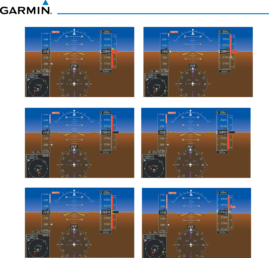
190-00928-04 Rev. A
Garmin G1000 Pilot’s Guide for the Beechcraft 200/B200 Series
479
HAZARD AVOIDANCE
Corrective Climb
Level Off, Level Off
Preventative Don’t Climb Corrective Don’t Descend
Preventative Don’t Climb and Don’t Descent
Greater than 500 FPM
Corrective Descend
Figure 6-190 Example Resolution Advisory Displays
Garmin G1000 Pilot’s Guide for the Beechcraft 200/B200 Series
190-00928-04 Rev. A480
HAZARD AVOIDANCE
SYSTEM TEST
The TCAS II system can be tested using either PFD or MFD softkeys.
On the PFD:
1) Press the XPDR/TFC Softkey.
2) Press the TCAS Softkey.
3) Press the TEST Softkey.
On the MFD:
1) Turn the large
FMS
Knob to select the Map Page Group.
2) Turn the small
FMS
Knob
to select the Traffic Map Page.
3) Turn the Range knob to set the range to 2/6 nm to allow for full traffic test pattern display.
4) Select the TEST Softkey.
Or:
1) Press the MENU Key
2) Turn the small
FMS
knob
to select ‘Test Mode’.
3) Press the ENT Key.
During a TCAS II system test, the G1000 displays a traffic test pattern appears on the Traffic Map Page of
the MFD, and on the PFD Inset Traffic Map (which appears if not already displayed.) The PFD displays a
Resolution Advisory (RA) alert annunciation, and vertical speed indicator indicating not to descend, and not
to climb greater than 2000 feet per minute (Figure 6-191). The system test takes approximately eight seconds
to complete.
Condition Voice Alert
System Test Passed “TCAS Two System Test Passed”
System Test Failed “TCAS Two System Test Failed”
Table 6-48 Garmin GTS 8000 System Test Voice Alerts
Visual annunciations will also indicate a system test has failed (Tables 6-49, 6-50, 6-51).
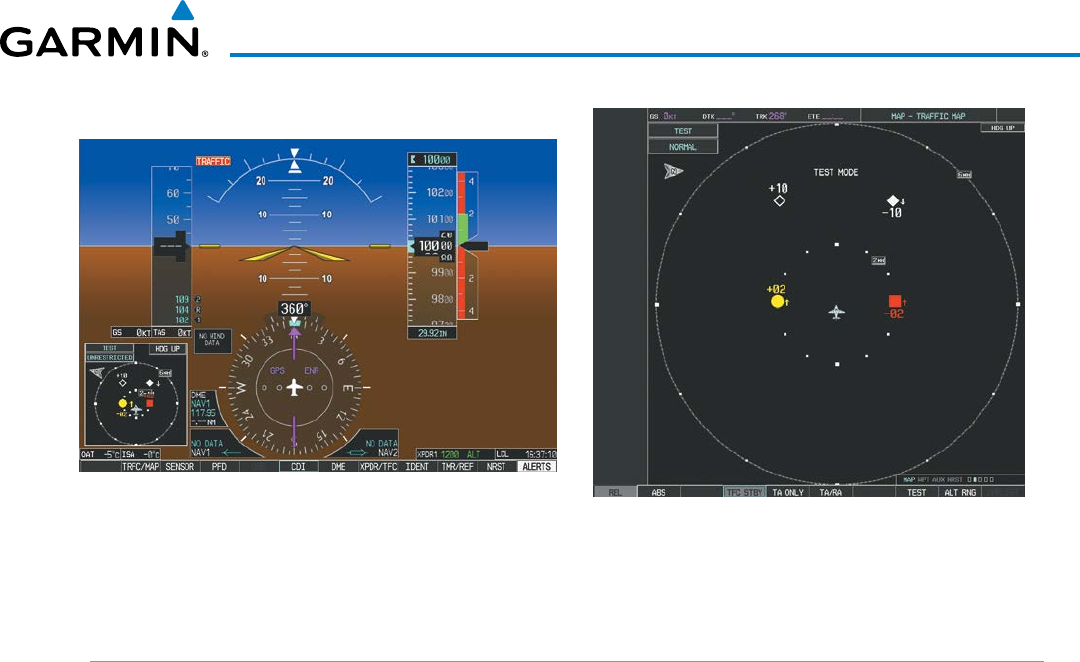
190-00928-04 Rev. A
Garmin G1000 Pilot’s Guide for the Beechcraft 200/B200 Series
481
HAZARD AVOIDANCE
PFD
MFD Traffic Map Page
Figure 6-191 TCAS II System Test Displays
OPERATION
To display TCAS II Traffic, the system must be in TA ONLY or TA/RA Mode. These modes can be accessed
on the PFD or on the Traffic Map Page of the MFD.
Switching from standby mode to TA only or TA/RA mode:
On the MFD:
1) Turn the large
FMS
Knob to select the Map Page Group.
2) Turn the small
FMS
Knob
to select the Traffic Map Page.
3) Select the TA ONLY or TA/RA Softkey
Or:
1) Press the MENU Key.
2) Turn the small
FMS
knob
to select ‘TA Only Mode’ or ‘TA/RA Mode’.
3) Press the ENT Key. The unit switches from Standby Mode to TA Only or TA/RA Mode as necessary.
On the PFD:
1) Press the XPDR/TFC Softkey.
2) Press the MODE Softkey.
3) Press the TA Only or TA/RA Softkey
Switching from TA ONLY or TA/RA mode to standby mode:
On the MFD:
1) Turn the large
FMS
Knob to select the Map Page Group.
2) Turn the small
FMS
Knob
to select the Traffic Map Page.
3) Select the TFC STBY Softkey
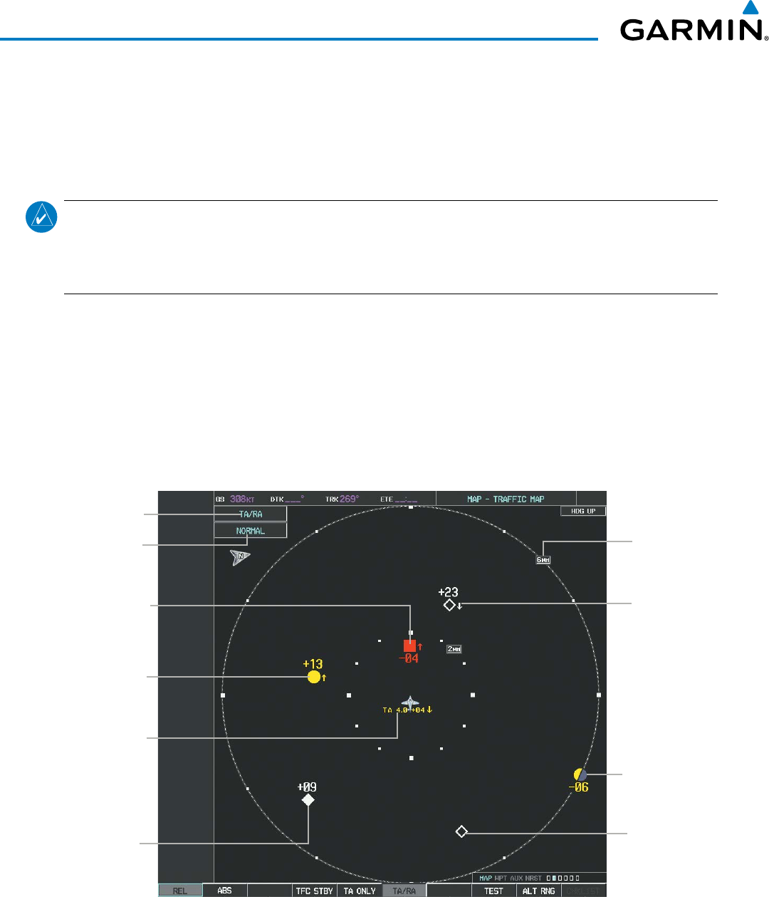
Garmin G1000 Pilot’s Guide for the Beechcraft 200/B200 Series
190-00928-04 Rev. A482
HAZARD AVOIDANCE
Or:
1) Press the MENU Key.
2) Turn the small
FMS
knob
to select ‘Traffic Standby Mode’.
3) Press the ENT Key.
NOTE: The GTS 8000 TCAS II system automatically selects TA ONLY Mode when the aircraft is below 1000’
AGL. After landing, the GTS 80000 automatically selects STANDBY Mode. If the installed TCAS II traffic
system is not a Garmin GTS 8000, refer to the applicable documentation for system-specific automatic
traffic mode selections.
TRAFFIC MAP PAGE
The Map - Traffic Map Page shows surrounding TCAS II traffic data in relation to the aircraft’s current
position and altitude, without basemap clutter. It is the principal map page for viewing TCAS II traffic.
Aircraft orientation is always heading up unless there is no valid heading. Map range is adjustable with the
RANGE Knob from 2 to 40 nm, as indicated by the map range rings.
The traffic operating mode and altitude display mode are annunciated in the upper left corner of the Traffic
Map Page.
Figure 6-192 Traffic Map Page
Operating
Mode
Altitude
Mode
Traffic Advisory,
1300’ Above,
Climbing
Proximity
Traffic, 900’
Above, Level
Traffic Display
Range
Indicator
“Non-Bearing”
(Bearing Unknown)
Resolution Advisory,
Distance 4 nm, 400’
Above, Descending
Traffic Advisory
Off Scale, 600’
Below, Level
Other Non-
Threat Traffic,
Altitude Not
Reported
Resolution
Advisory,
400’ Below,
Climbing
Other Non-
Threat Traffic,
2300’ Above,
Descending

190-00928-04 Rev. A
Garmin G1000 Pilot’s Guide for the Beechcraft 200/B200 Series
483
HAZARD AVOIDANCE
Displaying traffic on the Traffic Map Page:
1) Turn the large
FMS
Knob to select the Map Page Group.
2) Turn the small
FMS
Knob
to select the Traffic Map Page.
3) Select the TA ONLY or TA/RA Softkey to begin displaying traffic. TA ONLY or TA/RA is displayed in the Traffic
mode field.
4) Select the REL or ABS Softkey to display the relative or absolute altitude of other aircraft. When absolute
altitude is displayed, the system may revert to displaying relative altitude after 30 seconds if the TCAS II system
is providing altitude which is not corrected for the local barometric pressure setting.
5) Select the TFC STBY Softkey to place the system in the Standby mode. STANDBY is displayed in the Traffic
mode field.
6) Turn the RANGE Knob clockwise to display a larger area or counter-clockwise to display a smaller area.
altituDe DiSPlay
The flight crew can select the volume of airspace in which non-threat and proximity traffic is displayed.
Traffic Advisories (TAs) and Resolution Advisories (RAs) outside of these limits will always be shown.
Changing the altitude range:
On the PFD:
1) Press the XPDR/TFC Softkey.
2) Press the TCAS Softkey.
3) Press the ALT RNG Softkey.
4) Press one of the following altitude range Softkeys:
• ABOVE: Displays non-threat and proximity traffic from 9900 feet above the aircraft to 2700 feet below the
aircraft. Typically used during climb phase of flight.
• NORMAL: Displays non-threat and proximity traffic from 2700 feet above the aircraft to 2700 feet below
the aircraft. Typically used during enroute phase of flight.
• BELOW: Displays non-threat and proximity traffic from 2700 feet above the aircraft to 9900 feet below the
aircraft. Typically used during descent phase of flight.
• UNREST (unrestricted): All traffic is displayed
5) Press the BACK Softkey.
On the MFD:
1) On the Traffic Map Page, select the
ALT RNG
Softkey.
2) Select one of the following Softkeys (see softkey description in step 4 above):
• ABOVE
• NORMAL
• BELOW
• UNRESTRICTED
3) To return to the Traffic Page, select the BACK Softkey.
Or:

Garmin G1000 Pilot’s Guide for the Beechcraft 200/B200 Series
190-00928-04 Rev. A484
HAZARD AVOIDANCE
1) Press the MENU Key.
2) Turn the small
FMS
Knob
to select one of the following (see softkey description in step 4 above):
• ABOVE
• NORMAL
• BELOW
• UNRESTRICTED
3) Select the ENT Softkey.
tRaFFic MaP Page DiSPlay Range
The display range on the Traffic Map Page can be changed at any time. Map range is adjustable with the
RANGE Knob from 2 to 40 nm, as indicated by the map range rings.
Changing the display range on the Traffic Map Page:
1) Turn the RANGE Knob.
2) The following range options are available:
• 2 nm
• 2 and 6 nm
• 6 and 12 nm
• 12 and 24 nm
• 24 and 40 nm
ADDITIONAL TRAFFIC DISPLAYS
Traffic information can be displayed on the following maps on the MFD when the unit is operating:
• Navigation Map Page
• Traffic Map Page
• Trip Planning Page
• Nearest Pages
• Active Flight Plan Page
Traffic information can also be displayed on the PFD when the Synthetic Vision Technology (SVT) option
is installed and enabled. See the Additional Features Section for details.
Displaying traffic information (MFD maps other than the Traffic Map Page):
1) Select the MAP Softkey.
2) Select the TRAFFIC Softkey. Traffic is now displayed on the map.
When traffic is selected on maps other than the Traffic Map Page, a traffic icon is shown to indicate traffic
is enabled for display (Figure 6-193).
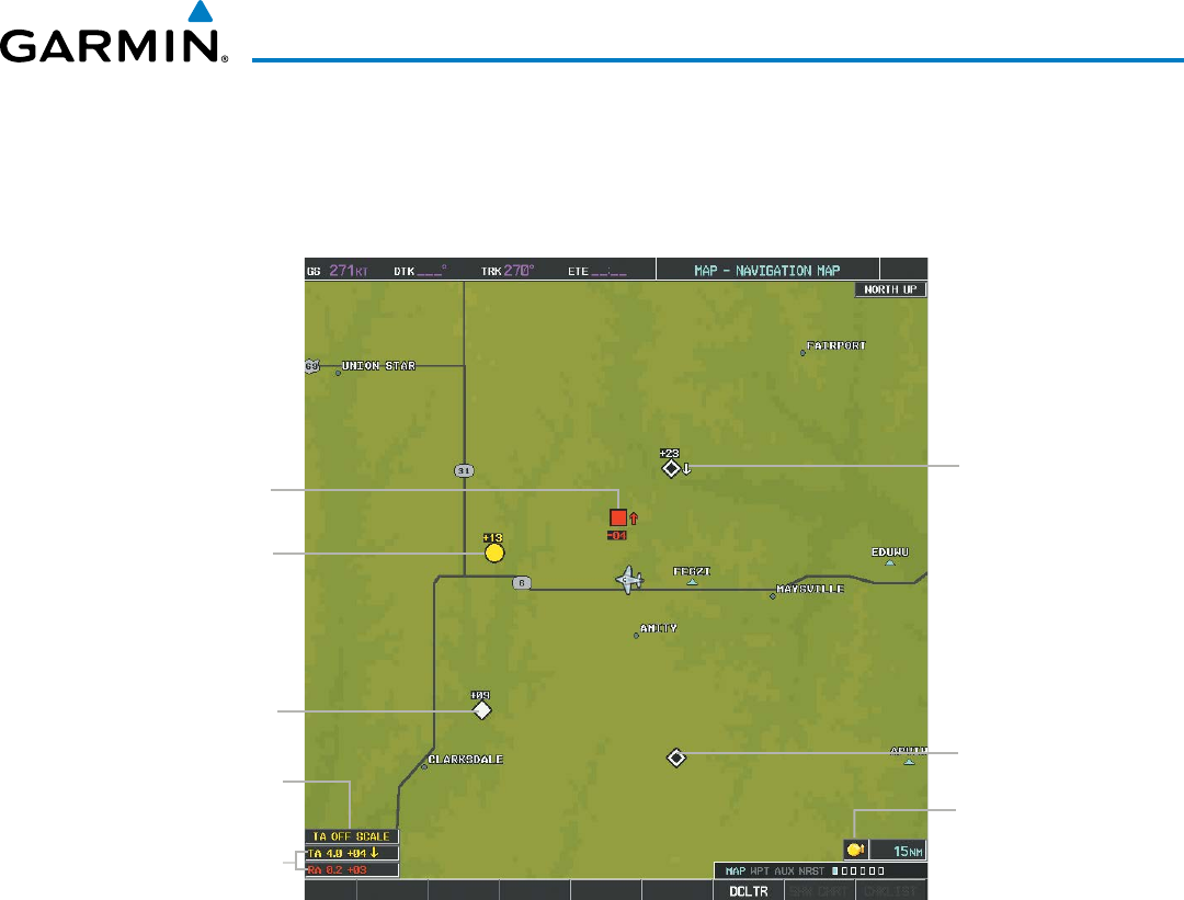
190-00928-04 Rev. A
Garmin G1000 Pilot’s Guide for the Beechcraft 200/B200 Series
485
HAZARD AVOIDANCE
Displaying traffic on the Navigation Map
1) Ensure the TCAS II system is operating. With the Navigation Map displayed, select the
MAP
Softkey.
2) Select the
TRAFFIC
Softkey. Traffic is now displayed on the map as shown in the figure.
Proximity
Traffic
Other
Non-
Threat
Traffic
TA Off Scale
Banner
Non-Bearing
Traffic and
Resolution
Advisories
Other Non-
Threat Traffic
Resolution
Advisory
Figure 6-193 TCAS II Traffic on Navigation Map
Traffic Status
Icon
Traffic
Advisory
Customizing the traffic display on the Navigation Map Page:
1) Select the Navigation Map Page.
2) Press the MENU Key.
3) With Map Setup highlighted, press the
ENT
Key (Figure 6-194).
4) Turn the small FMS Knob to select the Traffic Group and press the ENT Key (Figure 6-195).
5) Turn the large
FMS
Knob or press the
ENT
Key to scroll through the selections (Figure 6-196).
• TRAFFIC – Turns the display of traffic data on or off
• TRAFFIC MODE – Selects the traffic mode for display; select from:
- All Traffic - Displays all traffic
- TA/RA/PA - Displays Traffic Advisories, Resolution Advisories, and Proximity Advisories
- TA/RA ONLY - Displays Traffic Advisories and Resolution Advisories only
• TRAFFIC SMBL – Selects the maximum range at which traffic symbols are shown
• TRAFFIC LBL – Selects the maximum range at which traffic labels are shown with the option to turn off
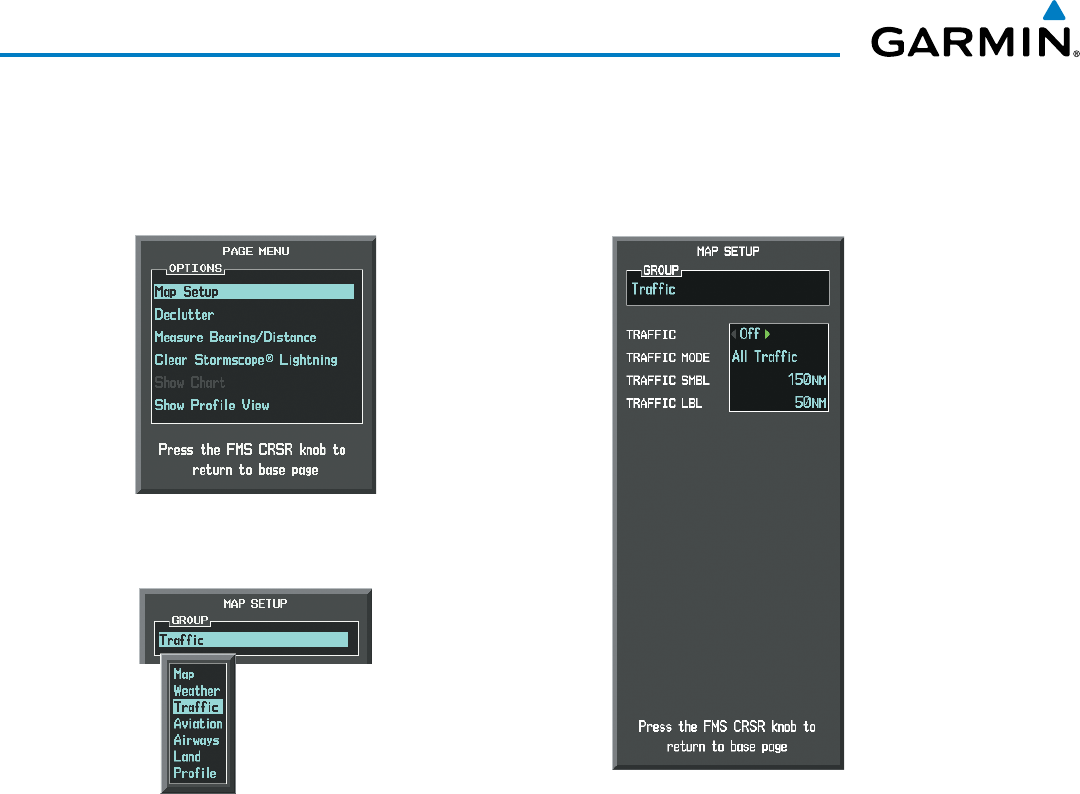
Garmin G1000 Pilot’s Guide for the Beechcraft 200/B200 Series
190-00928-04 Rev. A486
HAZARD AVOIDANCE
6) Turn the small
FMS
Knob to scroll through options (ON/OFF, range settings, etc.).
7) Press the
ENT
Key to select an option.
8) Press the FMS Knob or CLR Key to return to the Navigation Map Page.
Figure 6-195 Navigation Map Page Setup Menu
Figure 6-194 Navigation Map Page Menu
Figure 6-196 Navigation Map Page Setup Menu, Traffic Group
The Navigation Map Page Setup Menu also controls the display of traffic. The setup menu controls the map
range settings. Traffic data symbols and labels can be decluttered from the display. If a map range larger than
the map range setting is selected, the data is removed from the map. Maps besides the Traffic Map Page use
settings based on those selected for the Navigation Map Page.
Traffic information can also be displayed on the PFD Inset Map by pressing the TRFC/MAP Softkey. A
traffic map will appear in heading up orientation. Traffic information can also be overlaid with navigation,
topographic and optional datalink weather information.
Displaying additional information with Traffic on the PFD Inset Map.
1) Press the TRFC/MAP Softkey. Traffic map (TRFC-2) is displayed heading up.
2) Press the TRFC-2 Softkey.
3) Press the Softkey(s) for the item(s) to be included on the PFD Inset Map (TRAFFIC, TOPO, NEXRAD, XM LTNG)
4) Press the BACK Softkey.
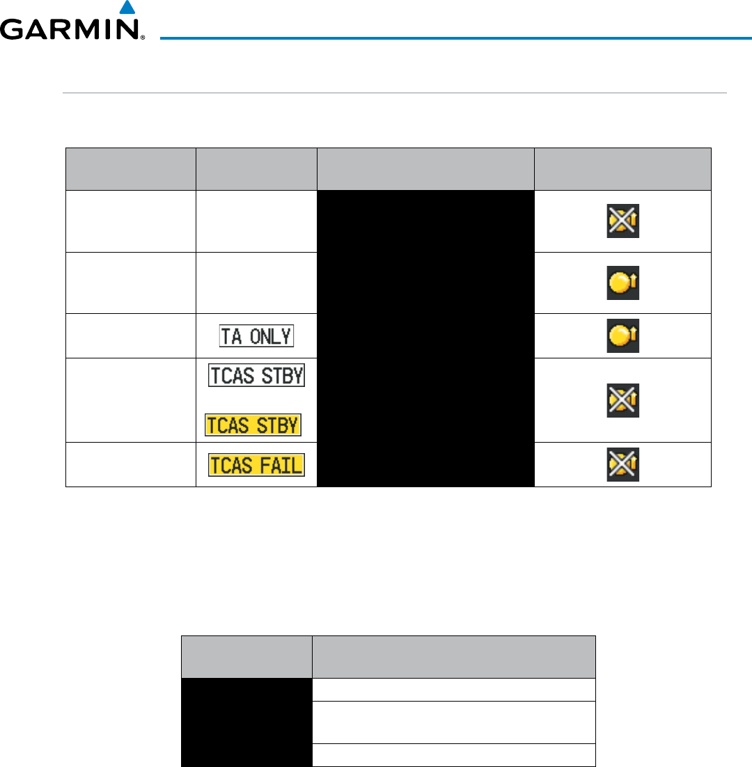
190-00928-04 Rev. A
Garmin G1000 Pilot’s Guide for the Beechcraft 200/B200 Series
487
HAZARD AVOIDANCE
SYSTEM STATUS
The traffic mode is annunciated in the upper left corner of the Traffic Map Page.
Mode PFD Mode
Annunciation
MFD Traffic Map Page Mode
Annunciation
Traffic Display Status Icon
(Other Maps)
TCAS II Self-test
Initiated (TEST) None
TEST
(‘TEST MODE’ also shown in white on
top center of page)
Traffic Advisory and
Resolution Advisory
(TA/RA)
None TA/RA
Traffic Advisory Only
(TA ONLY) TA ONLY
TCAS II Standby
(TFC STBY) o Or:
*
STANDBY
(also shown in white in center of page
on ground, yellow in the air)
TCAS II Failed** FAIL
* Annunciation appears in yellow while in the air.
** See Table 6-50 for additional failure annunciations.
Table 6-49 TCAS II Modes
If the TCAS II unit fails, an annunciation as to the cause of the failure is shown in the center of the Traffic
Map Page.
Traffic Map Page
Annunciation Description
NO DATA Data is not being received from the TCAS II unit
DATA FAILED Data is being received from the TCAS II unit, but the
unit is self-reporting a failure
FAILED Incorrect data format received from the TCAS II unit
Table 6-50 TCAS II Failure Annunciations
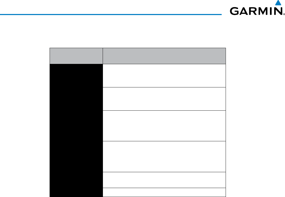
Garmin G1000 Pilot’s Guide for the Beechcraft 200/B200 Series
190-00928-04 Rev. A488
HAZARD AVOIDANCE
The annunciations to indicate the status of traffic information appear in a banner at the lower left corner of
maps on which traffic can be displayed.
Traffic Status Banner
Annunciation Description
RA OFF SCALE
A Resolution Advisory is outside the selected display
range*. Annunciation is removed when traffic comes within
the selected display range
TA OFF SCALE
A Traffic Advisory is outside the selected display range*.
Annunciation is removed when traffic comes within the
selected display range.
RA X.X ± XX ↕
System cannot determine bearing of Resolution Advisory**.
Annunciation indicates distance in nm, altitude separation
in hundreds of feet, and altitude trend arrow (climbing/
descending).
TA X.X ± XX ↕
System cannot determine bearing of Traffic Advisory**.
Annunciation indicates distance in nm, altitude separation
in hundreds of feet, and altitude trend arrow (climbing/
descending).
TRFC FAIL TCAS II unit has failed (unit is self-reporting a failure or
sending incorrectly formatted data)
NO TCAS DATA Data is not being received from the TCAS II unit
*Shown as symbol on Traffic Map Page
**Shown in center of Traffic Map Page
Table 6-51 TCAS II Traffic Status Annunciations

190-00928-04 Rev. A
Garmin G1000 Pilot’s Guide for the Beechcraft 200/B200 Series
489
AUTOMATIC FLIGHT CONTROL SYSTEM
SECTION 7 AUTOMATIC FLIGHT CONTROL SYSTEM
7.1 AFCS OVERVIEW
NOTE: The approved Pilot’s Operating Handbook (POH) and FAA Approved Airplane Flight Manual (AFM)
always supersedes this Pilot’s Guide.
The GFC 700 is a digital Automatic Flight Control System (AFCS), fully integrated within the G1000 System
avionics architecture. The System Overview section provides a block diagram to support this system description.
GFC 700 AFCS functionality is distributed across the following Line Replaceable Units (LRUs):
• GDU 1040A Primary Flight Displays (PFDs) (2)
• GMC 710 AFCS Control Unit
• GIA 63W Integrated Avionics Units (IAUs) (2)
• GSA 80 AFCS Servos (4)
• GSM 85A / GSM 86 Servo Gearboxes (4)
The GFC 700 AFCS can be divided into these main operating functions:
• Flight Director (FD) — The Beechcraft 200/B200 has two flight directors, each operating within an IAU and
referred to as pilot-side and copilot-side. Commands for the selected flight director are displayed on both
PFDs.
The flight director provides:
– Command Bars showing pitch/roll guidance
– Vertical/lateral mode selection and processing
– Autopilot communication
• Autopilot (AP) — Autopilot operation occurs within the pitch, roll, and pitch trim servos. It also provides
servo monitoring and automatic flight control in response to flight director steering commands, Attitude and
Heading Reference System (AHRS) attitude and rate information, and airspeed.
• Yaw Damper (YD) — The yaw servo is self-monitoring and provides Dutch roll damping and turn coordination
in response to yaw rate, roll angle, lateral acceleration, and airspeed.
• Manual Electric Pitch Trim (MEPT) — The pitch trim servo provides manual electric pitch trim capability
when the autopilot is not engaged.
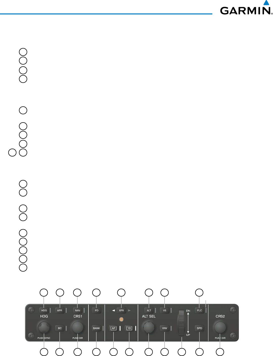
Garmin G1000 Pilot’s Guide for the Beechcraft 200/B200 Series
190-00928-04 Rev. A
490
AUTOMATIC FLIGHT CONTROL SYSTEM
AFCS CONTROL UNIT
The AFCS Control Unit is positioned above the MFD, and has the following controls:
1
HDG Key Selects/deselects Heading Select Mode
2
APR Key Selects/deselects Approach Mode
3
NAV Key Selects/deselects Navigation Mode
4
FD Key Activates/deactivates the flight director only
Pressing once turns on the selected flight director in the default vertical and lateral
modes. Pressing again deactivates the flight director and removes the Command
Bars. If the autopilot is engaged, the key is disabled.
5
XFR Key Transfers between the pilot and copilot flight directors and controls which flight
director the autopilot is tracking
6
ALT Key Selects/deselects Altitude Hold Mode
7
VS Key Selects/deselects Vertical Speed Mode
8
FLC Key Selects/deselects Flight Level Change Mode
9
17
CRS Knobs Adjust the Selected Course (while in VOR, LOC, or OBS Mode) in 1° increments on
the Horizontal Situation Indicator (HSI) of the corresponding PFD
Press to re-center the Course Deviation Indicator (CDI) and return course pointer
directly TO the bearing of the active waypoint/station
10
SPD Key Toggles Airspeed Reference between IAS and Mach for Flight Level Change Mode
11
NOSE UP/DN
Wheel
Adjusts the reference in Pitch Hold, Vertical Speed, and Flight Level Change modes
(see Table 7-2 for change increments in each mode)
12
VNV Key Selects/deselects Vertical Path Tracking Mode for Vertical Navigation flight control
13
ALT SEL Knob Controls the Selected Altitude in 100-ft increments (a finer resolution of 10 feet is
available under approach conditions)
14
YD Key Engages/disengages the yaw damper
15
AP Key Engages/disengages the autopilot
16
BANK Key Manually selects/deselects Low Bank Mode
18
BC Key Selects/deselects Backcourse Mode
19
HDG Knob Adjusts the Selected Heading and bug in 1° increments on the HSI (both PFDs)
Press to synchronize the Selected Heading to the current heading on the pilot-side PFD
Figure 7-1 GMC 710 AFCS Control Unit
1 2 3 4 5 6 7 8
Annunciator
Light
10 917 16 15 14 13 12 111819

190-00928-04 Rev. A
Garmin G1000 Pilot’s Guide for the Beechcraft 200/B200 Series
491
AUTOMATIC FLIGHT CONTROL SYSTEM
ADDITIONAL AFCS CONTROLS
The following AFCS controls are located separately from the AFCS Control Unit:
AP/YD DISC TRIM
INTRPT Switch
(Autopilot
Disconnect/Trim
Interrupt)
Disengages the autopilot, yaw damper, and flight director and interrupts pitch trim
operation
An AP/YD DISC Switch is located on each control wheel.
This switch may be used to acknowledge an autopilot disconnect alert and mute the
associated aural tone.
CWS Button
(Control Wheel
Steering)
While pressed, allows manual control of the aircraft while the autopilot is engaged and
synchronizes the flight director’s Command Bars with the current aircraft pitch (if
not in a Vertical Navigation, Glideslope, or Glidepath Mode) and roll (if in Roll Hold
Mode)
A CWS Button is located on each control wheel.
Upon release of the CWS Button, the flight director may establish new pitch and roll
references, depending on the current vertical and lateral modes. CWS operation
details are discussed in the respective mode sections of this manual.
GA Button
(Go Around)
Selects flight director Takeoff (on ground) or Go Around (in air) Mode
If an approach procedure is loaded this button also activates the missed approach when
the selected navigation source is GPS or when the navigation source is VOR/LOC
and a valid frequency has been tuned. Unless a compatible lift computer is installed,
pressing the GA Button disengages the autopilot.
The GA Button is located on the left throttle.
MEPT Switch
(Manual Electric
Pitch Trim)
Used to command manual electric pitch trim
An MEPT Switch is located on each control wheel.
The pilot side MEPT Switch has priority over the copilot side MEPT Switch.
This composite switch is split into left and right sides. The left switch is the ARM
contact and the right switch controls the DN (forward) and UP (rearward) contacts.
Pushing the MEPT ARM Switch disengages the autopilot, if currently engaged, but
does not affect yaw damper operation. The MEPT ARM Switch may be used to
acknowledge an autopilot disconnect alert and mute the associated aural tone.
Manual trim commands are generated only when both sides of the switch are operated
simultaneously. If either side of the switch is active separately for more than three
seconds, MEPT function is disabled and ‘PTRM’ is displayed as the AFCS Status
Annunciation on the PFDs. The function remains disabled until both sides of the
switch are inactivated.

Garmin G1000 Pilot’s Guide for the Beechcraft 200/B200 Series
190-00928-04 Rev. A
492
AUTOMATIC FLIGHT CONTROL SYSTEM
BASIC AUTOPILOT OPERATION
This section provides an overview for autopilot engagement and disengagement. A more detailed description
follows in Section 7.5.
• Autopilot Engagement — The autopilot may be engaged by pushing the AP Key on the AFCS Control Unit.
Annunciations regarding the engagement are indicated on the PFD.
• Autopilot Engagement with Flight Director Off — Upon engagement, the autopilot will be set to hold the
current attitude of the airplane, if the flight director was not previously on. In this case, ‘PIT’ and ‘ROL’ will be
annunciated.
• Autopilot Engagement with Flight Director On — If the flight director is on, the autopilot will smoothly
pitch and roll the airplane to capture the FD command bars. The prior flight director modes remain unchanged.
• Autopilot Disengagement — The most common way to disconnect the autopilot is to press and release the
AP/YD DISC Switch, which is located on the control stick. An autopilot disconnect tone will be heard and
annunciated on the PFD. Other ways to disconnect the autopilot include:
– Pressing the AP Key on the AFCS Control Unit
– Pressing the GA Switch (located on the left throttle)
– Operating the MEPT Switch (located on each control wheel)
– Pulling the autopilot circuit breaker
In the event of unexpected autopilot behavior, pressing and holding the AP/YD DISC Switch will disconnect
the autopilot and remove all power to the servos.
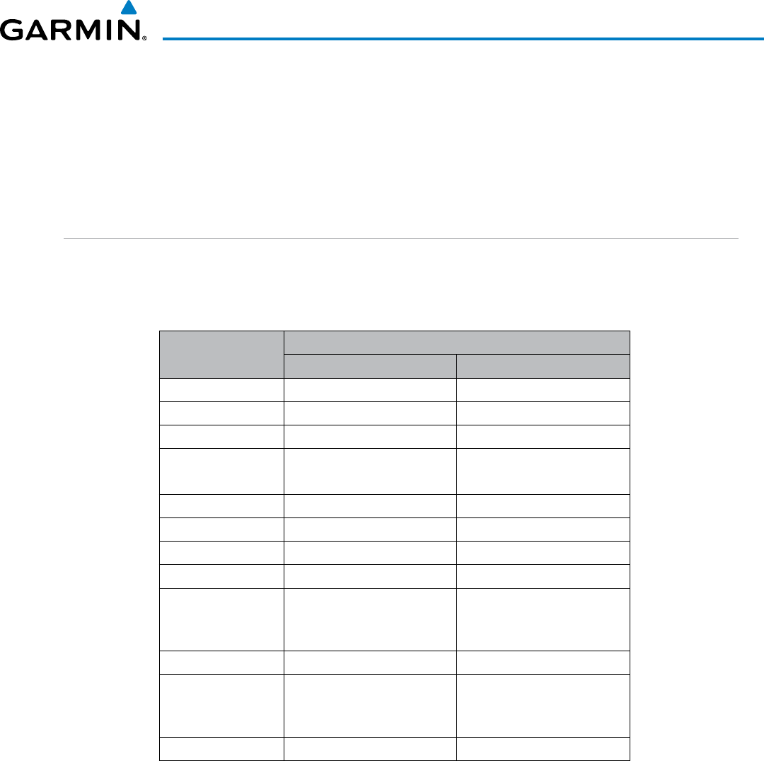
190-00928-04 Rev. A
Garmin G1000 Pilot’s Guide for the Beechcraft 200/B200 Series
493
AUTOMATIC FLIGHT CONTROL SYSTEM
7.2 FLIGHT DIRECTOR OPERATION
The flight director function provides pitch and roll commands to the AFCS and displays them on the PFDs.
With the flight director active, the aircraft can be hand-flown to follow the path shown by the Command Bars.
Maximum commanded pitch (−15°, +20°) and roll (25°) angles, vertical acceleration, and roll rate are limited to
values established during AFCS certification. The flight director also provides commands to the autopilot.
ACTIVATING THE FLIGHT DIRECTOR
An initial press of a key listed in Table 7-1 (when the flight director is not active) activates the pilot-side flight
director in the listed modes. The flight director may be turned off and the Command Bars removed from the
displays by pressing the FD Key again. The FD Key is disabled when the autopilot is engaged.
Control Pressed Modes Selected
Lateral Vertical
FD Key Roll Hold (default) ROL Pitch Hold (default) PIT
AP Key Roll Hold (default) ROL Pitch Hold (default) PIT
CWS Button Roll Hold (default) ROL Pitch Hold (default) PIT
GA Button Takeoff (on ground)
Go Around (in air)
TO
GA
Takeoff (on ground)
Go Around (in air)
TO
GA
ALT Key Roll Hold (default) ROL Altitude Hold ALT
VS Key Roll Hold (default) ROL Vertical Speed VS
FLC Key Roll Hold (default) ROL Flight Level Change FLC
VNV Key Roll Hold (default) ROL Vertical Path Tracking* VPTH
NAV Key Navigation**
GPS
VOR
LOC
Pitch Hold (default) PIT
BC Key Backcourse*** BC Pitch Hold (default) PIT
APR Key Approach**
GPS
VOR
LOC
Pitch Hold (default) PIT
HDG Key Heading Select HDG Pitch Hold (default) PIT
*Valid VNV flight plan must be entered before VNV Key press activates flight director.
**The selected navigation receiver must have a valid VOR or LOC signal or active GPS
course before
NAV
or
APR
Key press activates flight director.
***The selected navigation receiver must have a valid LOC signal before
BC
Key press
activates flight director.
Table 7-1 Flight Director Activation
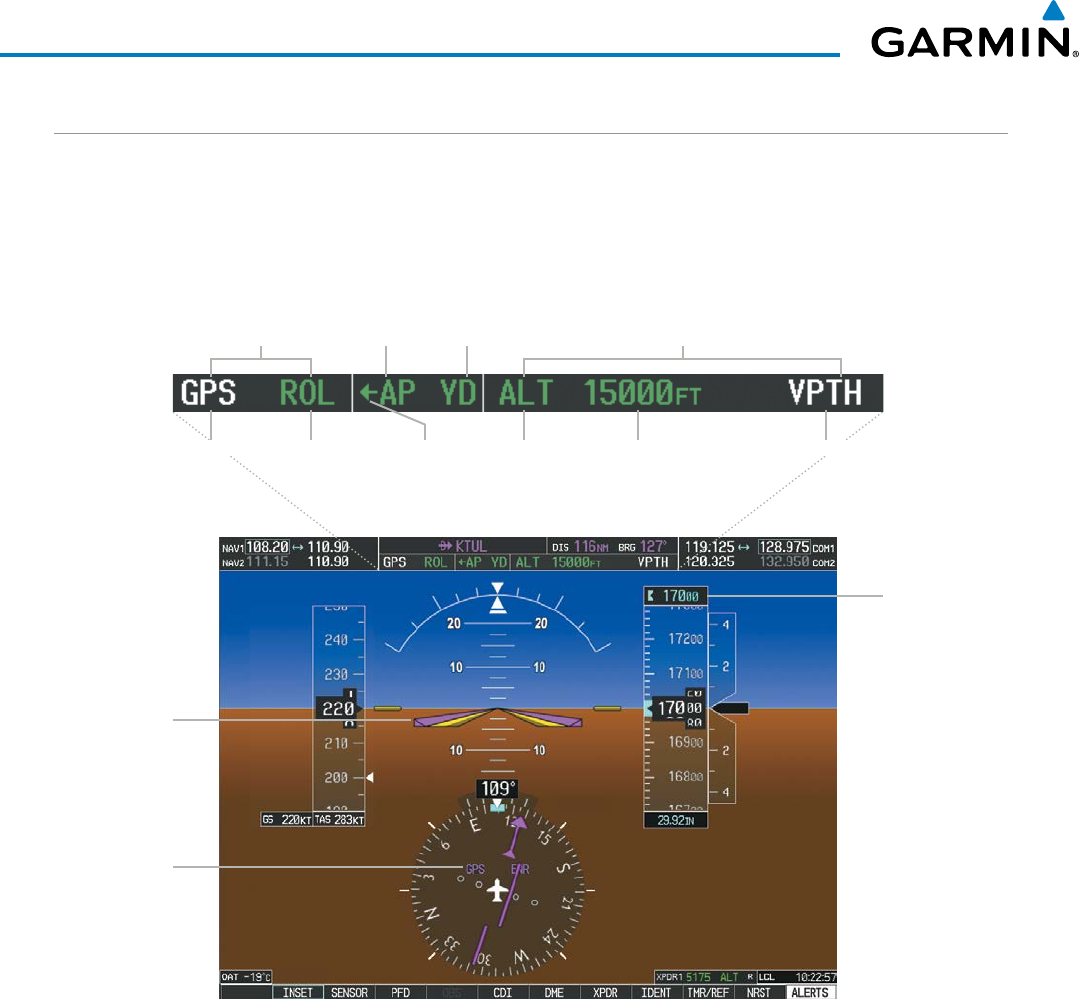
Garmin G1000 Pilot’s Guide for the Beechcraft 200/B200 Series
190-00928-04 Rev. A
494
AUTOMATIC FLIGHT CONTROL SYSTEM
AFCS STATUS BOX
Flight director mode annunciations are displayed on the PFDs when the flight director is active. Flight
director selection and autopilot and yaw damper statuses are shown in the center of the AFCS Status Box.
Lateral flight director modes are displayed on the left and vertical on the right. Armed modes are displayed in
white and active in green.
Figure 7-2 PFD AFCS Display
Selected
Altitude
GPS is
Selected
Navigation
Source
Command
Bars
AFCS Status Box
Yaw
Damper
Status
Flight Director
Indicator Arrow
Lateral Modes
Active
Autopilot
Status
Active Mode
Reference
Armed
Vertical Modes
Armed
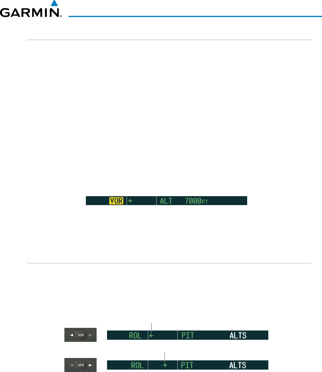
190-00928-04 Rev. A
Garmin G1000 Pilot’s Guide for the Beechcraft 200/B200 Series
495
AUTOMATIC FLIGHT CONTROL SYSTEM
FLIGHT DIRECTOR MODES
Flight director modes are normally selected independently for the pitch and roll axes. Unless otherwise
specified, all mode keys are alternate action (i.e., press on, press off). In the absence of specific mode selection,
the flight director reverts to the default pitch and/or roll modes. Mode keys on the AFCS controller are
accompanied by annunciator lights (Figure 7-1) which are illuminated when their respective modes are armed
or active.
Armed modes are annunciated in white and active in green in the AFCS Status Box. Under normal operation,
when the FD Key is pressed, the flight director reverts to the default mode(s) for the axis(es). Automatic
transition from armed to active mode is indicated by the white armed mode annunciation moving to the green
active mode field and flashing for 10 seconds.
If the information required to compute a flight director mode becomes invalid or unavailable, the flight
director automatically reverts to the default mode for that axis. A flashing yellow mode annunciation and
annunciator light indicate loss of sensor (ADC) or navigation data (VOR, LOC, GPS, VNV, SBAS) required to
compute commands. When such a loss occurs, the system automatically begins to roll the wings level (enters
Roll Hold Mode) or maintain the pitch angle (enters Pitch Hold Mode), depending on the affected axis. The
flashing annunciation stops when the affected mode key is pressed or another mode for the axis is selected. If
after 10 seconds no action is taken, the flashing annunciation stops.
Figure 7-3 Loss of VOR Signal
The flight director is automatically disabled if the attitude information required to compute the default flight
director modes becomes invalid or unavailable.
SWITCHING FLIGHT DIRECTORS
The GFC 700 in the Beechcraft 200/B200 has two flight directors, each operating within an IAU. The
autopilot follows the selected flight director only, indicated by an arrow pointing toward either the pilot or
copilot side, in the center of the AFCS Status Box. Flight directors may be switched by pressing the XFR Key.
The annunciator light arrow for the selected flight director is also illuminated beside the XFR Key. When the
flight directors are switched, the vertical and lateral modes revert to default.
Figure 7-4 Flight Director Selection Indications
Pilot-side Flight Director Selected
Copilot-side Flight Director Selected
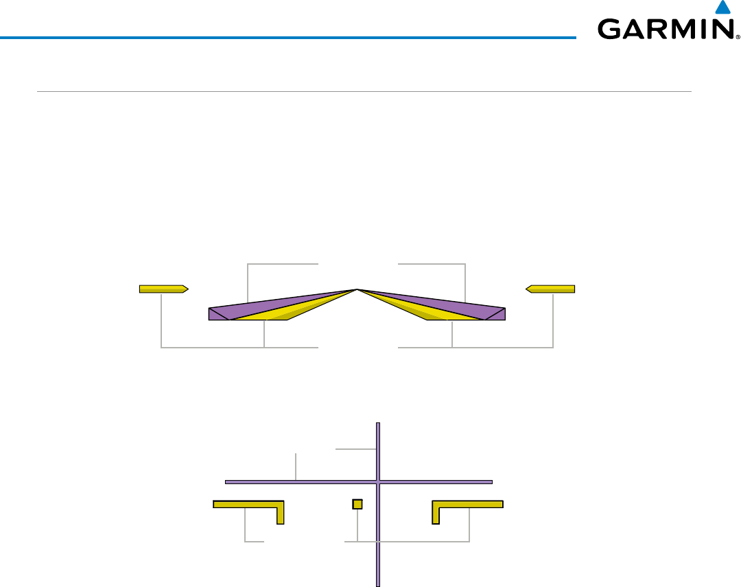
Garmin G1000 Pilot’s Guide for the Beechcraft 200/B200 Series
190-00928-04 Rev. A
496
AUTOMATIC FLIGHT CONTROL SYSTEM
COMMAND BARS
Upon activation of the flight director, Command Bars are displayed in magenta on the PFDs as a single
cue or cross pointers. The Aircraft Symbol (in yellow) changes to accommodate the Command Bar format;
the Command Bars do not override the Aircraft Symbol. The single-cue Command Bars (Figure 7-5) move
together vertically to indicate pitch commands and bank left or right to indicate roll commands. Command
Bars displayed as a cross pointer (Figure 7-6) move independently to indicate pitch (horizontal bar) and roll
(vertical bar) commands. Both PFDs show the same Command Bar format. If a compatible lift computer is
installed, the cross-pointer option will be unavailable.
Aircraft Symbol
Command Bars
Figure 7-6 Cross-pointer Command Bars
Figure 7-5 Single-cue Command Bars
Aircraft Symbol
Command Bars
Changing Command Bar format:
1) Use the FMS Knob to select the AUX - System Setup Page on the MFD.
2) Press the FMS Knob to activate the cursor.
3) Turn the large FMS Knob to highlight ‘Format Active’ in the ‘Flight Director’ box.
4) Turn the small FMS Knob to highlight the desired format.
’SNGL CUE’ to display Command Bars as a single cue (Aircraft Symbol in figure 7-5).
Or:
’X-POINTER’ to display Command Bars as a cross-pointer (Aircraft Symbol in Figure 7-6).
If the attitude information being sent to the flight director becomes invalid or unavailable, the Command Bars
are removed from the display. The flight director Command Bars also disappear if the pitch exceeds +30˚/-20˚
or bank exceeds 65˚.
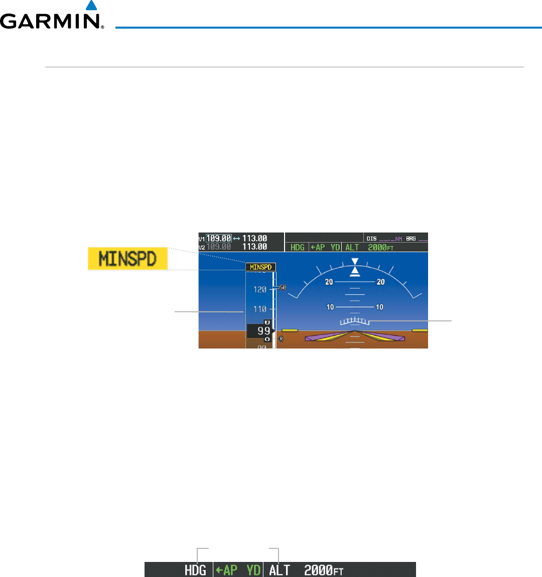
190-00928-04 Rev. A
Garmin G1000 Pilot’s Guide for the Beechcraft 200/B200 Series
497
AUTOMATIC FLIGHT CONTROL SYSTEM
UNDERSPEED PROTECTION
Underspeed Protection is available when the optional Electronic Stability and Protection (ESP) system is
installed and the autopilot is on. It is designed to discourage aircraft operation below minimum established
airspeeds.
When the aircraft reaches a predetermined airspeed (specific to each flap setting), a yellow MINSPD
annunciation (Figure 7-7) will appear above the airspeed indicator. When aircraft angle of attack is within four
degrees of stall warning, the Pitch Limit Indicator (Figure 7-7) will be displayed approximately four degrees
above the aircraft symbol on the pitch attitude indicator. If deceleration continues, the Pitch Limit Indicator
will move downward on the pitch attitude indicator until coincident with the aircraft symbol at stall warning
angle of attack.
Pitch Limit
Indicator
Figure 7-7 MINSPD Annunciation and Pitch Limit Indicator
Airspeed
Indicator
If the aircraft continues to decelerate, Underspeed Protection functionality depends on which vertical flight
director mode is selected. For the purpose of this discussion, the vertical flight director modes can be divided
into two categories: Those in which it is important to maintain altitude for as long as possible (altitude-critical
modes), and those in which maintaining altitude is less crucial (non-altitude critical modes).
ALTITUDE-CRITICAL MODES (ALT, GS, GP, TO, GA, FLC)
If the aircraft declerates to stall warning, the lateral and vertical flight director modes will change from
active to armed (Figure 7-8), and the autopilot will provide input causing the aircraft to pitch down and the
wings to level.
Lateral and
Vertical FD
Modes Armed
Figure 7-8 Lateral and Vertical Flight Director Modes Armed
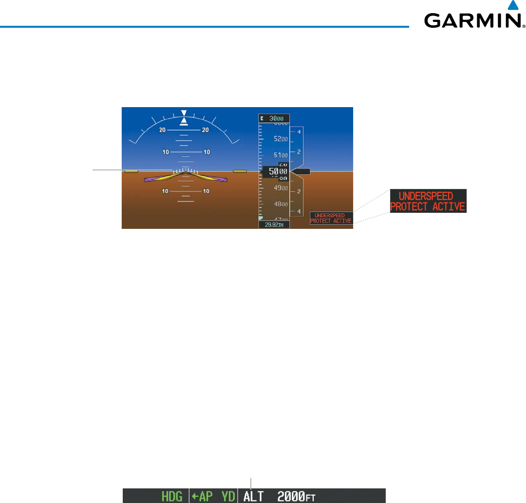
Garmin G1000 Pilot’s Guide for the Beechcraft 200/B200 Series
190-00928-04 Rev. A
498
AUTOMATIC FLIGHT CONTROL SYSTEM
An aural “AIRSPEED” alert will sound every five seconds and a red “UNDERSPEED PROTECT ACTIVE”
annunciation (Figure 7-9) will appear to the right of the vertical speed indicator. The pitch down force will
continue until the aircraft reaches a pitch attitude at which IAS equals the IAS at which stall warning turns
off, plus two knots.
Figure 7-9 Underspeed Protect Active Annunciation
Pitch Limit
Indicator
When airspeed increases (as a result of adding power/thrust) to above the IAS at which stall warning turns
off, plus two knots, the autopilot will cause the aircraft to pitch up until recapturing the vertical reference.
The vertical and lateral flight director modes will change from armed to active, and when aircraft angle of
attack reaches approximately five degrees below stall warning angle of attack, the Pitch Limit Indicator will
be removed.
NON-ALTITUDE CRITICAL MODES (VS, VNAV, IAS,)
When the airspeed trend vector (specific to each flap setting) reaches a predetermined airspeed, a single
aural “AIRSPEED” will sound, alerting the pilot to the impending underspeed condition. If the aircraft
decelerates to an IAS below the minimum commandable autopilot airspeed, a red “UNDERSPEED PROTECT
ACTIVE” annunciation (Figure 7-9) will appear to the right of the vertical speed indicator. The vertical flight
director mode will change from active to armed (Figure 7-10), and the autopilot will cause the aircraft to pitch
down until reaching a pitch attitude at which IAS equals the minimum commandable autopilot airspeed.
Vertical FD
Mode Armed
Figure 7-10 Vertical Flight Director Mode Armed
When airspeed increases (as a result of adding power/thrust) to an IAS above the minimum commandable
autopilot airspeed, the autopilot will cause the aircraft to pitch up until recapturing the vertical reference.
The vertical flight director mode will change from armed to active, and when aircraft angle of attack reaches
approximately five degrees below stall warning angle of attack, the Pitch Limit Indicator will be removed.

190-00928-04 Rev. A
Garmin G1000 Pilot’s Guide for the Beechcraft 200/B200 Series
499
AUTOMATIC FLIGHT CONTROL SYSTEM
7.3 VERTICAL MODES
Table 7-2 lists the vertical modes with their corresponding controls and annunciations. The mode reference is
displayed next to the active mode annunciation for Altitude Hold, Vertical Speed, and Flight Level Change modes.
The NOSE UP/DN Wheel can be used to change the vertical mode reference while operating under Pitch Hold,
Vertical Speed, or Flight Level Change Mode.
Vertical Mode Description Control Annunciation Reference
Range
Reference
Change
Increment
Pitch Hold
Holds the current aircraft pitch
attitude; may be used to climb/
descend to the Selected Altitude
(default) PIT -15° to
+20° 0.5°
Selected Altitude Capture Captures the Selected Altitude * ALTS
Altitude Hold Holds the current Altitude Reference ALT Key ALT nnnnn fT
Vertical Speed
Maintains the current aircraft vertical
speed; may be used to climb/descend
to the Selected Altitude
VS Key VS nnnn fpm -4000 to
+4000 fpm 100 fpm
Flight Level Change, IAS Hold Maintains the current aircraft
airspeed (in IAS or Mach) while the
aircraft is climbing/descending to the
Selected Altitude
FLC Key
FLC nnn kT 100 to
259 kt 1 kt
Flight Level Change, Mach Hold FLC M .nnn M 0.15 to
0.52 M 0.01
Vertical Path Tracking Captures and tracks descent legs of
an active vertical profile
VNV
Key VPTH
VNV Target Altitude Capture Captures the Vertical Navigation
(VNV) Target Altitude ** ALTV
Glidepath Captures and tracks the SBAS
glidepath on approach APR
Key
GP
Glideslope Captures and tracks the ILS glideslope
on approach GS
Takeoff
Commands a constant pitch angle
and wings level on the ground in
preparation for takeoff GA
Button
TO 8.6°
Go Around*** Commands a constant pitch angle
and wings level in the air GA 8°
Level
Autopilot engages and commands
pitch angle necessary to establish
zero vertical fpm
**** LVL N/A
* ALTS armed automatically when PIT, VS, FLC, TO, or GA active, and under VPTH when Selected Altitude is to be captured
instead of VNV Target Altitude
** ALTV armed automatically under VPTH when VNV Target Altitude is to be captured instead of Selected Altitude
***Go Around mode disengages the autopilot unless a compatible lift computer is installed.
**** Level mode can only become activated as a function of Electronic Stability and Protection (ESP). Refer to the Additional
Features section for a detailed discussion of the optional ESP feature.
Table 7-2 Flight Director Vertical Modes
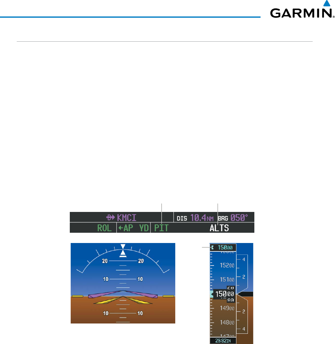
Garmin G1000 Pilot’s Guide for the Beechcraft 200/B200 Series
190-00928-04 Rev. A
500
AUTOMATIC FLIGHT CONTROL SYSTEM
PITCH HOLD MODE (PIT)
When the flight director is activated (the FD Key is pressed) or switched (the XFR Key is pressed), Pitch Hold
Mode is selected by default. Pitch Hold Mode is indicated as the active vertical mode by the ‘PIT’ annunciation.
This mode may be used for climb or descent to the Selected Altitude (shown above the Altimeter), since
Selected Altitude Capture Mode is automatically armed when Pitch Hold Mode is activated.
In Pitch Hold Mode, the flight director maintains a constant pitch attitude, the pitch reference. The pitch
reference is set to the aircraft pitch attitude at the moment of mode selection. If the aircraft pitch attitude
exceeds the flight director pitch command limitations, the flight director commands a pitch angle equal to the
nose-up/down limit.
CHANGING THE PITCH REFERENCE
When operating in Pitch Hold Mode, the pitch reference can be adjusted by:
• Using the
NOSE UP/DN
Wheel
• Pressing the
CWS
Button, hand-flying the aircraft to establish a new pitch reference, then releasing the
CWS
Button
Selected Altitude
Capture Mode Armed
Pitch Hold
Mode Active
Figure 7-11 Pitch Hold Mode
Selected
Altitude
Command Bars Maintain
Desired Pitch Reference
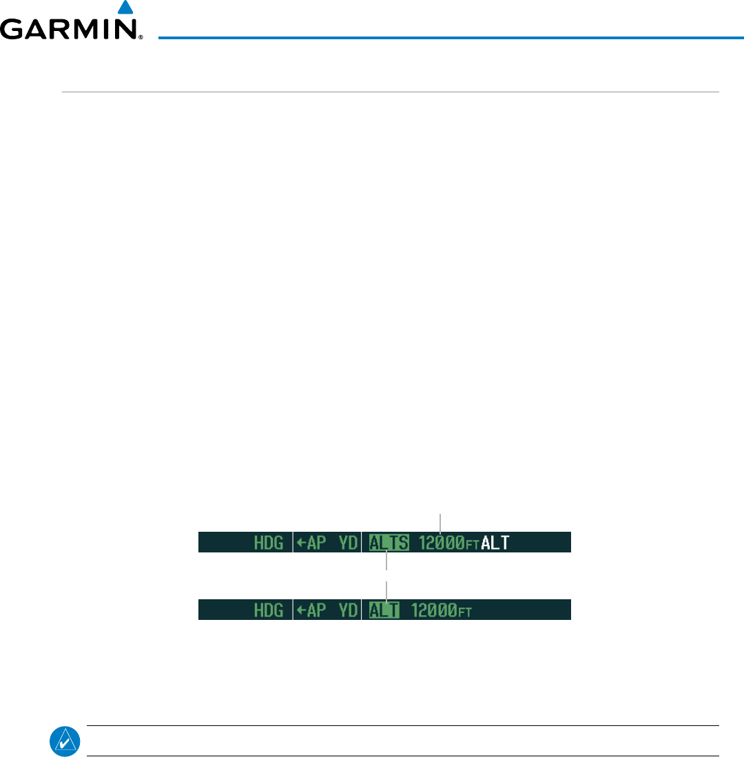
190-00928-04 Rev. A
Garmin G1000 Pilot’s Guide for the Beechcraft 200/B200 Series
501
AUTOMATIC FLIGHT CONTROL SYSTEM
SELECTED ALTITUDE CAPTURE MODE (ALTS)
Selected Altitude Capture Mode is automatically armed with activation of the following modes:
• Pitch Hold
• Vertical Speed
• Flight Level Change
• Takeoff/Go Around (if the Selected Altitude is at
least 400 feet above the current aircraft altitude)
• Vertical Path Tracking (if the Selected Altitude is to
be captured instead of the VNV Target Altitude)
The white ‘ALTS’ annunciation indicates Selected Altitude Capture Mode is armed (see Figure 7-11 for
example). The ALT SEL Knob is used to set the Selected Altitude (shown above the Altimeter) until Selected
Altitude Capture Mode becomes active.
As the aircraft nears the Selected Altitude, the flight director automatically transitions to Selected Altitude
Capture Mode with Altitude Hold Mode armed (Figure 7-12). This automatic transition is indicated by the
green ‘ALTS’ annunciation flashing for up to 10 seconds and the appearance of the white ‘ALT’ annunciation.
The Selected Altitude is shown as the Altitude Reference beside the ‘ALTS’ annunciation.
At 50 feet from the Selected Altitude, the flight director automatically transitions from Selected Altitude
Capture to Altitude Hold Mode and holds the Selected Altitude (shown as the Altitude Reference). As Altitude
Hold Mode becomes active, the white ‘ALT’ annunciation moves to the active vertical mode field and flashes
green for 10 seconds to indicate the automatic transition.
Figure 7-12 Automatic Mode Transitions During Altitude Capture
Flash up to 10 sec, Indicating Automatic Transition
Altitude Reference
(in this case, equal to
Selected Altitude)
CHANGING THE SELECTED ALTITUDE
NOTE: Pressing the CWS Button while in Selected Altitude Capture Mode does not cancel the mode.
Use of the ALT SEL Knob to change the Selected Altitude while Selected Altitude Capture Mode is active
causes the flight director to revert to Pitch Hold Mode with Selected Altitude Capture Mode armed for the
new Selected Altitude.
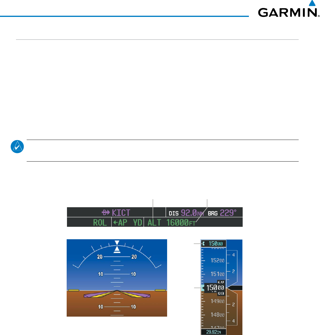
Garmin G1000 Pilot’s Guide for the Beechcraft 200/B200 Series
190-00928-04 Rev. A
502
AUTOMATIC FLIGHT CONTROL SYSTEM
ALTITUDE HOLD MODE (ALT)
Altitude Hold Mode can be activated by pressing the
ALT
Key; the flight director maintains the current aircraft
altitude (to the nearest 10 feet) as the Altitude Reference. The flight director’s Altitude Reference, shown in the
AFCS Status Box, is independent of the Selected Altitude, displayed above the Altimeter. Altitude Hold Mode
active is indicated by a green ‘ALT’ annunciation in the AFCS Status Box.
Altitude Hold Mode is automatically armed when the flight director is in Selected Altitude Capture Mode
(see Figure 7-12). Selected Altitude Capture Mode automatically transitions to Altitude Hold Mode when
the altitude error is less than 50 feet. In this case, the Selected Altitude becomes the flight director’s Altitude
Reference.
CHANGING THE ALTITUDE REFERENCE
NOTE: Turning the ALT SEL Knob while in Altitude Hold Mode changes the Selected Altitude, but not the
flight director’s Altitude Reference, and does not cancel the mode.
With the
CWS
Button depressed, the aircraft can be hand-flown to a new Altitude Reference. When the
CWS
Button is released at the desired altitude, the new altitude is established as the Altitude Reference.
Figure 7-13 Altitude Hold Mode
Selected
Altitude
Bug
Selected
Altitude
Altitude Hold
Mode Active Altitude
Reference
Command Bars Hold Pitch Attitude
to Maintain Altitude Reference
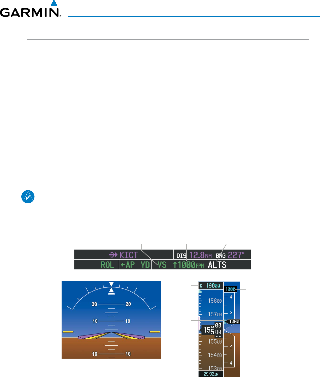
190-00928-04 Rev. A
Garmin G1000 Pilot’s Guide for the Beechcraft 200/B200 Series
503
AUTOMATIC FLIGHT CONTROL SYSTEM
VERTICAL SPEED MODE (VS)
In Vertical Speed Mode, the flight director acquires and maintains a Vertical Speed Reference. Current aircraft
vertical speed (to the nearest 100 fpm) becomes the Vertical Speed Reference at the moment of Vertical Speed
Mode activation. This mode may be used for climb or descent to the Selected Altitude (shown above the
Altimeter) since Selected Altitude Capture Mode is automatically armed when Vertical Speed Mode is selected.
When Vertical Speed Mode is activated by pressing the
VS
Key, ‘VS’ is annunciated in green in the AFCS Status
Box along with the Vertical Speed Reference. The Vertical Speed Reference is also displayed above the Vertical
Speed Indicator. A Vertical Speed Reference Bug corresponding to the Vertical Speed Reference is shown on
the indicator.
CHANGING THE VERTICAL SPEED REFERENCE
The Vertical Speed Reference (shown both in the AFCS Status Box and above the Vertical Speed Indicator)
may be changed by:
• Using the
NOSE UP/DN
Wheel
• Pressing the
CWS
Button, hand-flying the aircraft to attain a new Vertical Speed Reference, then releasing
the
CWS
Button
NOTE: If the Selected Altitude is reached during CWS maneuvering, the Altitude Reference is not changed.
To adjust the Altitude Reference in this case, the CWS Button must be pressed again after the Selected
Altitude is reached.
Figure 7-14 Vertical Speed Hold Mode
Vertical
Speed
Reference
Bug
Vertical
Speed
Reference
Selected
Altitude
Command Bars Indicate Climb to
Attain Vertical Speed Reference
Vertical
Speed
Reference
Selected
Altitude Capture
Mode Armed
Vertical Speed
Mode Active

Garmin G1000 Pilot’s Guide for the Beechcraft 200/B200 Series
190-00928-04 Rev. A
504
AUTOMATIC FLIGHT CONTROL SYSTEM
FLIGHT LEVEL CHANGE MODE (FLC)
NOTE: The Selected Altitude should be set before selecting Flight Level Change Mode.
Flight Level Change Mode is selected by pressing the
FLC
Key. This mode acquires and maintains the
Airspeed Reference (in IAS or Mach) while climbing or descending to the Selected Altitude (shown above
the Altimeter). When Flight Level Change Mode is active, the flight director continuously monitors Selected
Altitude, airspeed, Mach, and altitude.
The Airspeed Reference is set to the current airspeed upon mode activation. Flight Level Change Mode is
indicated by a green ‘FLC’ annunciation beside the Airspeed Reference in the AFCS Status Box. The Airspeed
Reference is also displayed directly above the Airspeed Indicator, along with a bug corresponding to the Airspeed
Reference along the tape.
Engine power must be adjusted to allow the autopilot to fly the aircraft at a pitch attitude corresponding
to the desired flight profile (climb or descent) while maintaining the Airspeed Reference. The flight director
maintains the current altitude until either engine power or the Airspeed Reference are adjusted and does not
allow the aircraft to climb or descend away from the Selected Altitude.
CHANGING THE AIRSPEED REFERENCE
The Airspeed Reference (shown in both the AFCS Status Box and above the Airspeed Indicator) may be
adjusted by:
• Using the
NOSE UP/DN
Wheel
• Pressing the
CWS
Button, hand-flying the aircraft to attain a new Airspeed Reference, then releasing the
CWS
Button
NOTE: If the Selected Altitude is reached during CWS maneuvering, the Airspeed Reference is not changed.
To adjust the Airspeed Reference in this case, the CWS Button must be pressed again after the Selected
Altitude is reached.
During climb, the pilot must select the Airspeed Reference (IAS or Mach), automatic switching does not
occur. For descent, if Mach airspeed reference is selected (above 16,000 ft), the aircraft descends in Mach
until the Mach airspeed reference reaches 250 KIAS, at which point the airspeed reference automatically
switches to IAS at that airspeed value. The system determines aircraft climb or descent by the relationship
between the current and Selected altitudes.
Airspeed Reference units can be manually toggled between IAS and Mach units using the SPD Key. When
the FLC Airspeed Reference is displayed in Mach, the Airspeed Reference Bug is displayed on the Airspeed
Indicator at the IAS corresponding to the selected Mach target speed and the current Mach number is shown
only in the AFCS Status Box.
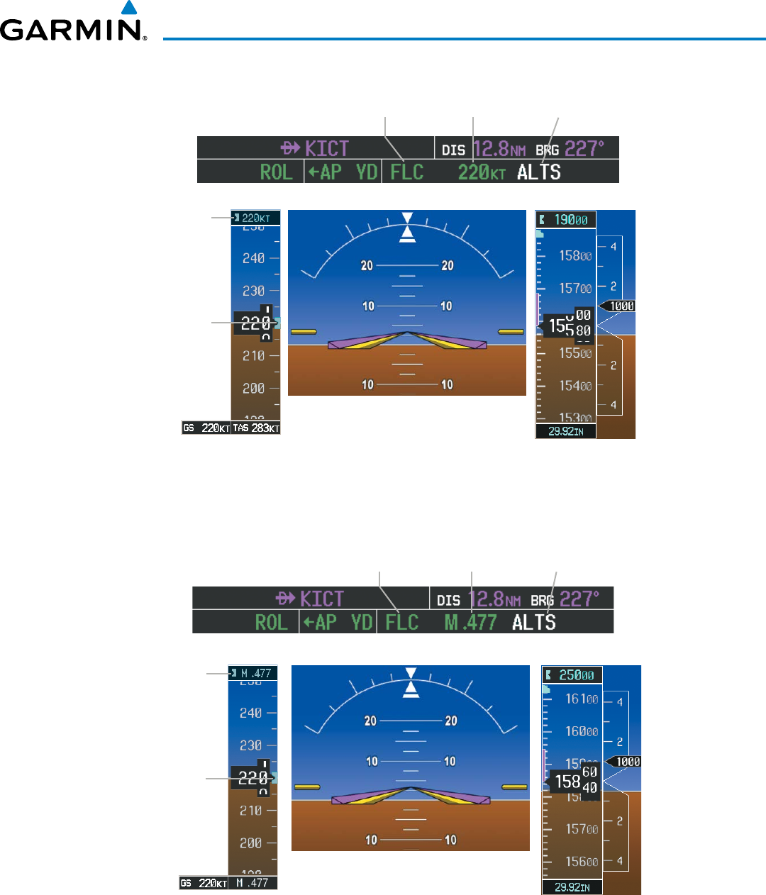
190-00928-04 Rev. A
Garmin G1000 Pilot’s Guide for the Beechcraft 200/B200 Series
505
AUTOMATIC FLIGHT CONTROL SYSTEM
Figure 7-15 Flight Level Change Mode (IAS)
Airspeed
Reference
Bug
Airspeed
Reference
Command Bars Indicate Climb
to Attain Selected Altitude
Airspeed
Reference
Selected
Altitude Capture
Mode Armed
Flight Level
Change Mode
Active
Figure 7-16 Flight Level Change Mode (Mach)
Airspeed
Reference
Bug
Airspeed
Reference
(Mach)
Command Bars Indicate Climb
to attain Selected Altitude
Selected
Altitude Capture
Mode Armed
Flight Level
Change Mode
Active
Airspeed
Reference
(Mach)
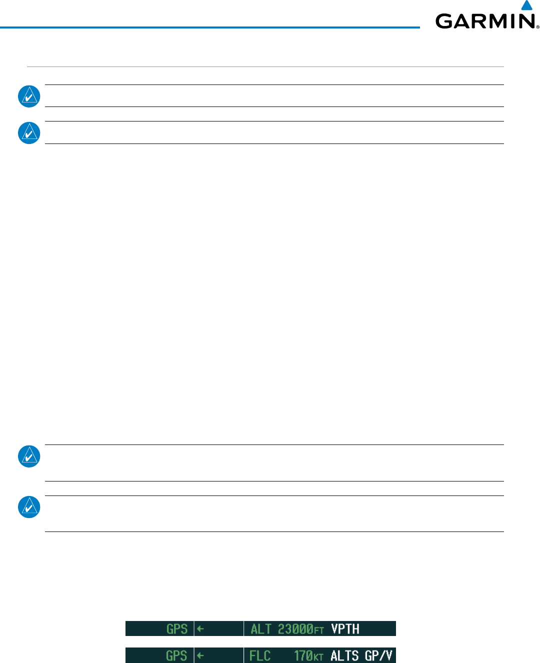
Garmin G1000 Pilot’s Guide for the Beechcraft 200/B200 Series
190-00928-04 Rev. A
506
AUTOMATIC FLIGHT CONTROL SYSTEM
VERTICAL NAVIGATION MODES (VPTH, ALTV)
NOTE: VNV is disabled when parallel track or Dead Reckoning Mode is active.
NOTE: The Selected Altitude takes precedence over any other vertical constraints.
Vertical Navigation (VNV) flight control is available for enroute/terminal cruise and descent operations any
time that VNV flight planning is available. Refer to the GPS Navigation Section for more information on VNV
flight plans. Conditions for availability include, but are not limited to:
• The selected navigation source is GPS.
• A VNV flight plan (with at least one altitude-constrained waypoint) or vertical direct-to is active.
• VNV is enabled (VNV ENBL Softkey pressed on the MFD).
• Crosstrack error is valid and within certain limits.
• Desired/actual track are valid or track angle error is within certain limits.
• The VNV Target Altitude of the active waypoint is no more than 250 ft above the current aircraft altitude.
The flight director may be armed for VNV at any time, but no target altitudes are captured during a climb.
The Command Bars provide vertical profile guidance based on specified altitudes (entered manually or loaded
from the database) at waypoints in the active flight plan or vertical direct-to. The appropriate VNV flight control
modes are sequenced by the flight director to follow the path defined by the vertical profile. Upon reaching
the last waypoint in the VNV flight plan, the flight director transitions to Altitude Hold Mode and cancels any
armed VNV modes.
VERTICAL PATH TRACKING MODE (VPTH)
NOTE: If another vertical mode key is pressed while Vertical Path Tracking Mode is selected, Vertical Path
Tracking Mode reverts to armed.
NOTE: Pressing the CWS Button while Vertical Path Tracking Mode is active does not cancel the mode. The
autopilot guides the aircraft back to the descent path upon release of the CWS Button.
When a vertical profile (VNV flight plan) is active and the VNV Key is pressed, Vertical Path Tracking
Mode is armed in preparation for descent path capture. ‘VPTH’ (or ‘/V’ when Glidepath or Glideslope Mode
is concurrently armed) is annunciated in white in addition to previously armed modes. If applicable, the
appropriate altitude capture mode is armed for capture of the next VNV Target Altitude (ALTV) or the Selected
Altitude (ALTS), whichever is greater.
Figure 7-17 Vertical Path Tracking Armed Annunciations
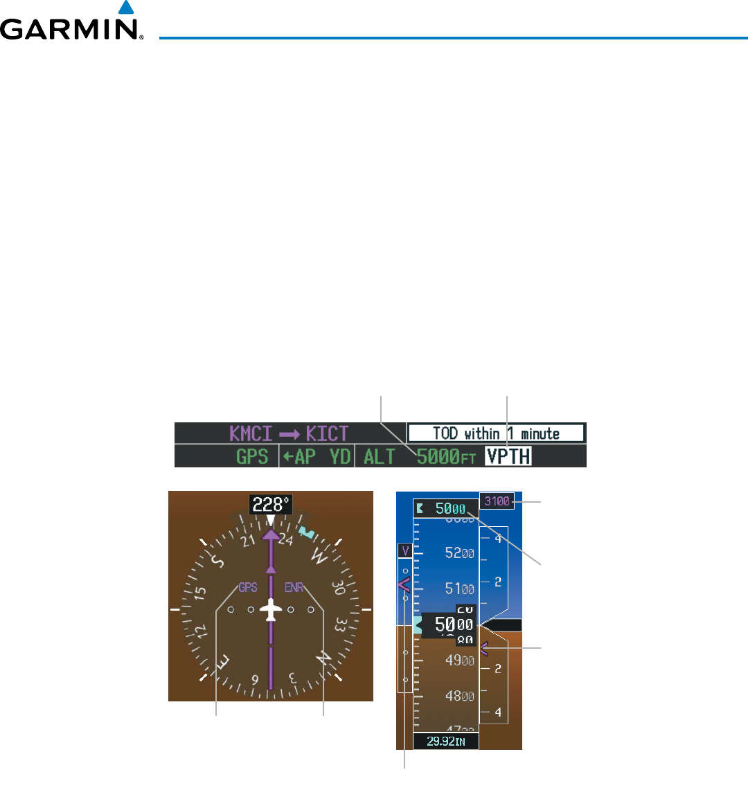
190-00928-04 Rev. A
Garmin G1000 Pilot’s Guide for the Beechcraft 200/B200 Series
507
AUTOMATIC FLIGHT CONTROL SYSTEM
Prior to descent path interception, the Selected Altitude must be set below the current aircraft altitude
by at least 75 feet. For the flight director to transition from Altitude Hold to Vertical Path Tracking Mode,
acknowledgment is required within five minutes of descent path interception by:
• Pressing the VNV Key
• Adjusting the Selected Altitude
If acknowledgment is not received within one minute of descent path interception, the white ‘VPTH’
annunciation starts to flash. Flashing continues until acknowledged or the descent path is intercepted. If
the descent is not confirmed by the time of interception, Vertical Path Tracking Mode remains armed and the
descent is not captured.
In conjunction with the “TOD [top of descent] within 1 minute” annunciation in the PFD Navigation Status
Box and the “Vertical track” voice message, VNV indications (VNV Target Altitude, vertical deviation, and
vertical speed required) appear on the PFDs in magenta (Figure 7-18).
Figure 7-18 Vertical Path Capture
GPS is Selected
Navigation
Source
Enroute
Phase of
Flight
Required
Vertical
Speed Bug
VNV Target
Altitude
Vertical
Deviation
Indicator
Selected
Altitude
Vertical Path Tracking
Armed (Flashing Indicates
Acknowledgment Required
Altitude Hold
Mode Active
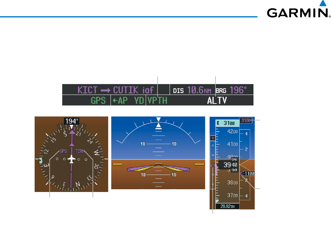
Garmin G1000 Pilot’s Guide for the Beechcraft 200/B200 Series
190-00928-04 Rev. A
508
AUTOMATIC FLIGHT CONTROL SYSTEM
When a descent leg is captured (i.e., vertical deviation becomes valid), Vertical Path Tracking becomes
active and tracks the descent profile (Figure 7-19). An altitude capture mode (‘ALTS’ or ‘ALTV’) is armed as
appropriate.
Figure 7-19 Vertical Path Tracking Mode
VNV Target Altitude
Capture Armed
Vertical Path
Tracking Active
GPS is Selected
Navigation
Source
Terminal
Phase of
Flight
Command Bars Indicate Descent to
Maintain Required Vertical Speed
VNV Target
Altitude
Required
Vertical
Speed Bug
Vertical Deviation
Indicator (VDI)
If the altimeter barometric setting is adjusted while Vertical Path Tracking is active, the flight director
increases/decreases the descent rate by up to 500 fpm to re-establish the aircraft on the descent path (without
commanding a climb). Adjusting the altimeter barometric setting creates discontinuities in VNV vertical
deviation, moving the descent path. For large adjustments, it may take several minutes for the aircraft to re-
establish on the descent path. If the change is made while nearing a waypoint with a VNV Target Altitude,
the aircraft may not re-establish on the descent path in time to meet the vertical constraint.

190-00928-04 Rev. A
Garmin G1000 Pilot’s Guide for the Beechcraft 200/B200 Series
509
AUTOMATIC FLIGHT CONTROL SYSTEM
autoMatic ReveRSion to PitcH HolD MoDe
Several situations can occur while Vertical Path Tracking Mode is active which cause the flight director to
revert to Pitch Hold Mode:
• Vertical deviation exceeds 200 feet during an overspeed condition.
• Vertical deviation experiences a discontinuity that both exceeds 200 feet in magnitude and results in the
vertical deviation exceeding 200 feet in magnitude. Such discontinuities are usually caused by flight plan
changes that affect the vertical profile.
• Vertical deviation becomes invalid (the Vertical Deviation Indicator is removed from the PFD).
• A display enters Reversionary Mode (this does not apply to an active vertical direct-to).
Unless VNV is disabled, Vertical Path Tracking Mode and the appropriate altitude capture mode become
armed following the reversion to Pitch Hold Mode to allow for possible profile recapture.
non-PatH DeScentS
Pitch Hold, Vertical Speed, and Flight Level Change modes can also be used to fly non-path descents
while VNV flight control is selected. If the VS or FLC Key is pressed while Vertical Path Tracking Mode is
selected, Vertical Path Tracking Mode reverts to armed along with the appropriate altitude capture mode to
allow profile re-capture.
Figure 7-20 Flight Level Change VNV Non-Path Descent
To prevent immediate profile re-capture, the following must be satisfied:
• At least 10 seconds have passed since the non-path transition was initiated
• Vertical deviation from the profile has exceeded 250 feet, but is now less than 200 feet
Pressing the VNV Key twice re-arms Vertical Path Tracking for immediate profile re-capture.
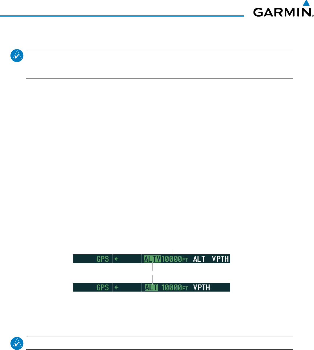
Garmin G1000 Pilot’s Guide for the Beechcraft 200/B200 Series
190-00928-04 Rev. A
510
AUTOMATIC FLIGHT CONTROL SYSTEM
VNV TARGET ALTITUDE CAPTURE MODE (ALTV)
NOTE: Armed VNV Target Altitude and Selected Altitude capture modes are mutually exclusive. However,
Selected Altitude Capture Mode is armed implicitly (not annunciated) whenever VNV Target Altitude Capture
Mode is armed.
VNV Target Altitude Capture is analogous to Selected Altitude Capture Mode and is armed automatically
after the VNV Key is pressed and the next VNV Target Altitude is to be intercepted before the Selected Altitude.
The annunciation ‘ALTV’ indicates that the VNV Target Altitude is to be captured. VNV Target Altitudes are
shown in the active flight plan or vertical direct-to, and can be entered manually or loaded from a database
(see the GPS Navigation Section for details). At the same time as “TOD within 1 minute” is annunciated in
the Navigation Status Box, the active VNV Target Altitude is displayed above the Vertical Speed Indicator.
As the aircraft nears the VNV Target Altitude, the flight director automatically transitions to VNV Target
Altitude Capture Mode with Altitude Hold Mode armed. This automatic transition is indicated by the green
‘ALTV’ annunciation flashing for up to 10 seconds and the appearance of the white ‘ALT’ annunciation. The
VNV Target Altitude is shown as the Altitude Reference beside the ‘ALTV’ annunciation and remains displayed
above the Vertical Speed Indicator. The Required Vertical Speed Indication (RSVI) is removed once VNV
Target Altitude Capture Mode becomes active.
At 50 feet from the VNV Target Altitude, the flight director automatically transitions from VNV Target
Altitude Capture to Altitude Hold Mode and tracks the level leg. As Altitude Hold Mode becomes active, the
white ‘ALT’ annunciation moves to the active vertical mode field and flashes green for 10 seconds to indicate
the automatic transition. The flight director automatically arms Vertical Path Tracking, allowing upcoming
descent legs to be captured and subsequently tracked.
Figure 7-21 Automatic Mode Transitions During Altitude Capture
Flash up to 10 sec, Indicating Automatic Transition
Altitude Reference (In This Case,
Equal To VNV Altitude Target)
cHanging tHe vnv taRget altituDe
NOTE: Pressing the CWS Button while in VNV Target Altitude Capture Mode does not cancel the mode.
Changing the current VNV Target Altitude while VNV Target Altitude Capture Mode is active causes the
flight director to revert to Pitch Hold Mode. Vertical Path Tracking and the appropriate altitude capture
mode are armed in preparation to capture the new VNV Target Altitude or the Selected Altitude, depending
on which altitude is to be intercepted first.
VNV target altitudes can be changed while editing the active flight plan (see the GPS Navigation Section
for details).
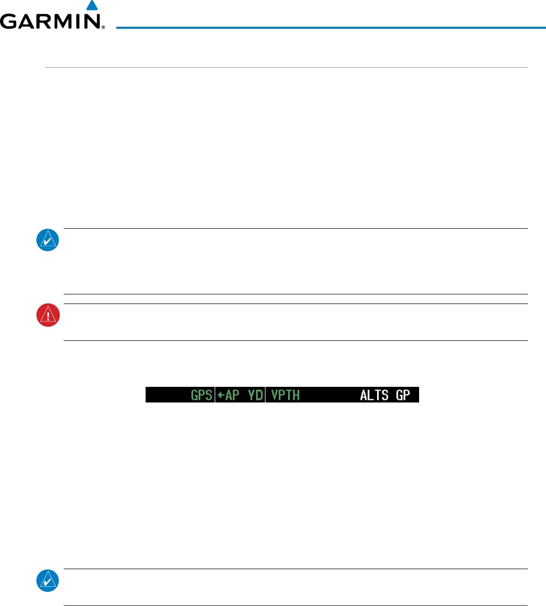
190-00928-04 Rev. A
Garmin G1000 Pilot’s Guide for the Beechcraft 200/B200 Series
511
AUTOMATIC FLIGHT CONTROL SYSTEM
GLIDEPATH MODE (GP)
Glidepath Mode is used to track the SBAS-based glidepath. When Glidepath Mode is armed, ‘GP’ is
annunciated in white in the AFCS Status Box.
Selecting Glidepath Mode:
1) Ensure a GPS approach is loaded into the active flight plan. The active waypoint must be part of the flight plan
(cannot be a direct-to a waypoint not in the flight plan).
2) Ensure that GPS is the selected navigation source (use the CDI Softkey to cycle through navigation sources if
necessary).
3) Press the APR Key.
NOTE: Some RNAV (GPS) approaches provide a vertical descent angle as an aid in flying a stabilized
approach. These approaches are NOT considered Approaches with Vertical Guidance (APV). Approaches
that are annunciated on the HSI as LNAV or LNAV+V are considered Nonprecision Approaches (NPA) and
are flown to an MDA even though vertical glidepath (GP) information may be provided.
WARNING: When flying an LNAV approach (with vertical descent angle) with the autopilot coupled, the
aircraft will not level off at the MDA even if the MDA is set in the altitude preselect.
Upon reaching the glidepath, the flight director transitions to Glidepath Mode and begins to capture and
track the glidepath.
Figure 7-22 Glidepath Mode Armed
Once the following conditions have been met, the glidepath can be captured:
• A GPS approach with vertical guidance (LPV, LNAV/VNAV, LNAV+V) is loaded into the active flight plan.
• The active waypoint is at or after the final approach fix (FAF).
• Vertical deviation is valid.
• The CDI is at less than full-scale deviation
• Automatic sequencing of waypoints has not been suspended (no ‘SUSP’ annunciation on the HSI)
NOTE: Pressing the CWS Button while Glidepath Mode is active does not cancel the mode. The autopilot
guides the aircraft back to the glidepath upon release of the CWS Button.
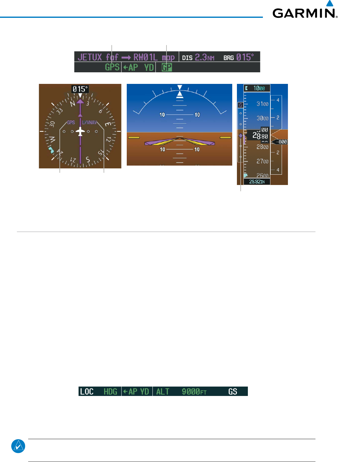
Garmin G1000 Pilot’s Guide for the Beechcraft 200/B200 Series
190-00928-04 Rev. A
512
AUTOMATIC FLIGHT CONTROL SYSTEM
Figure 7-23 Glidepath Mode
Glidepath
Mode Active
GPS Approach
Mode Active
Command Bars Indicate
Descent on Glidepath
Glidepath
Indicator
GPS is Selected
Navigation
Source
LNAV/VNAV
Approach
Active
GLIDESLOPE MODE (GS)
Glideslope Mode is available for LOC/ILS approaches to capture and track the glideslope. When Glideslope
Mode is armed (annunciated as ‘GS’ in white), LOC Approach Mode is armed as the lateral flight director mode.
Selecting Glideslope Mode:
1) Ensure a valid localizer frequency is tuned.
2) Ensure that LOC is the selected navigation source (use the CDI Softkey to cycle through navigation sources if
necessary).
3) Press the APR Key.
Or:
1) Ensure that GPS is the selected navigation source (use the CDI Softkey to cycle through navigation sources if
necessary).
2) Ensure a LOC/ILS approach is loaded into the active flight plan.
3) Ensure the corresponding LOC frequency is tuned.
4) Press the APR Key.
Figure 7-24 Glideslope Mode Armed
Once LOC is the navigation source, the localizer and glideslope can be captured. Upon reaching the glideslope,
the flight director transitions to Glideslope Mode and begins to capture and track the glideslope.
NOTE: Pressing the CWS Button while Glideslope Mode is active does not cancel the mode. The autopilot
guides the aircraft back to the glideslope upon release of the CWS Button.
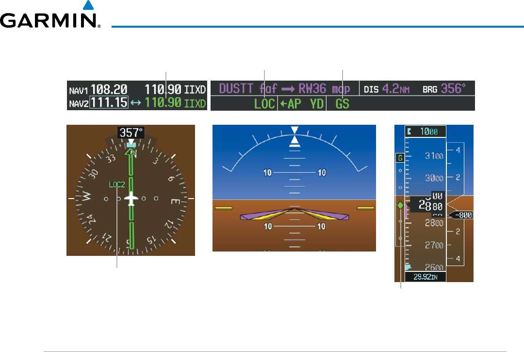
190-00928-04 Rev. A
Garmin G1000 Pilot’s Guide for the Beechcraft 200/B200 Series
513
AUTOMATIC FLIGHT CONTROL SYSTEM
Figure 7-25 Glideslope Mode
Command Bars Indicate Descent
on Localizer/Glideslope Path
NAV2 (localizer) is Selected
Navigation Source
Glideslope
Indicator
Glideslope
Mode Active
Approach
Mode Active
Active ILS
Frequency Tuned
TAKEOFF (TO) AND GO AROUND (GA) MODES
Go Around and Takeoff modes are coupled pitch and roll modes and are annunciated as both the vertical
and lateral modes when active. In these modes, the flight director commands a constant set pitch attitude and
wings level. The
GA Button
is used to select both modes. The mode entered by the flight director depends on
whether the aircraft is on the ground.
Takeoff Mode provides an attitude reference during rotation and takeoff. This mode can be selected only
while on the ground by pushing the GA Button. The flight director Command Bars assume a wings-level,
pitch-up attitude.
Pressing the GA Button while in the air activates the flight director in wings level, pitch-up attitudes, allowing
the execution of a missed approach or a go around.
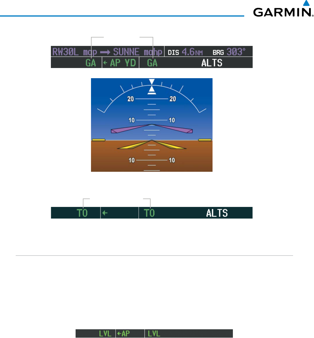
Garmin G1000 Pilot’s Guide for the Beechcraft 200/B200 Series
190-00928-04 Rev. A
514
AUTOMATIC FLIGHT CONTROL SYSTEM
Figure 7-26 Takeoff and Go Around Modes
Command Bars Indicate Climb
Takeoff Mode Active
Go Around
Mode Active
LEVEL MODE (LVL)
Level (LVL) mode becomes active only as a function of Electronic Stability and Protection (ESP). Refer to the
Additional Features section for a detailed discussion of the optional ESP feature.
When the normal flight envelope thresholds have been exceeded for more than 50% of the last 20 seconds,
Level mode is activated. The autopilot will engage and provide input to bring the aircraft back into straight
and level flight based on zero degrees roll angle and zero feet per minute vertical speed. An aural “ENGAGING
AUTOPILOT” alert sounds and the lateral and vertical flight director annunciations will display “LVL”. The
AFCS will remain in Level mode until the pilot selects another mode.
Figure 7-27 Level Mode
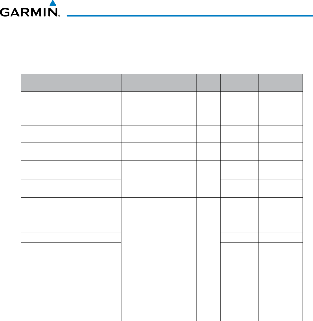
190-00928-04 Rev. A
Garmin G1000 Pilot’s Guide for the Beechcraft 200/B200 Series
515
AUTOMATIC FLIGHT CONTROL SYSTEM
7.4 LATERAL MODES
The following table relates each GFC 700 lateral mode to its respective control and annunciation. Refer to the
vertical modes section for information regarding Go Around and Takeoff modes.
Lateral Mode Description Control Annunciation Maximum Roll
Command Limit
Roll Hold
Holds the current aircraft roll
attitude or rolls the wings level,
depending on the commanded
bank angle
(default) ROL 25°
Low Bank Limits the maximum commanded
roll angle
BANK
Key * 15°
Heading Select Captures and tracks the Selected
Heading
HDG
Key HDG 25°
Navigation, GPS Arm/Capture/Track Captures and tracks the selected
navigation source (GPS, VOR,
LOC)
NAV
Key
GPS 25°
Navigation, VOR Enroute Arm/Capture/Track VOR 25°
Navigation, LOC Arm/Capture/Track
(No Glideslope) LOC 25°
Backcourse Arm/Capture/Track
Captures and tracks a
localizer signal for backcourse
approaches
BC Key BC 25°
Approach, GPS Arm/Capture/Track Captures and tracks the selected
navigation source (GPS, VOR,
LOC)
APR Key
GPS 25°
Approach, VOR Arm/Capture/Track VAPP 25°
Approach, ILS Arm/Capture/Track
(Glideslope Mode automatically armed) LOC 25°
Takeoff
Commands a constant pitch
angle and wings level on the
ground in preparation for takeoff GA
Button
TO Wings Level
Go Around** Commands a constant pitch
angle and wings level in the air GA Wings Level
Level Autopilot engages and
commands wings level *** LVL Wings Level
* No annunciation appears in the AFCS Status Box. The acceptable bank angle range is indicated in green along the Roll
Scale of the Attitude Indicator.
**Go Around mode disengages the autopilot unless a compatible lift computer is installed.
*** Level mode can only become activated as a function of Electronic Stability and Protection (ESP). Refer to the Additional
Features section for a detailed discussion of the optional ESP feature.
Table 7-3 Flight Director Lateral Modes
The CWS Button does not change lateral references for Heading Select, Navigation, Backcourse, or Approach
Mode. The autopilot guides the aircraft back to the Selected Heading/Course upon release of the CWS Button.
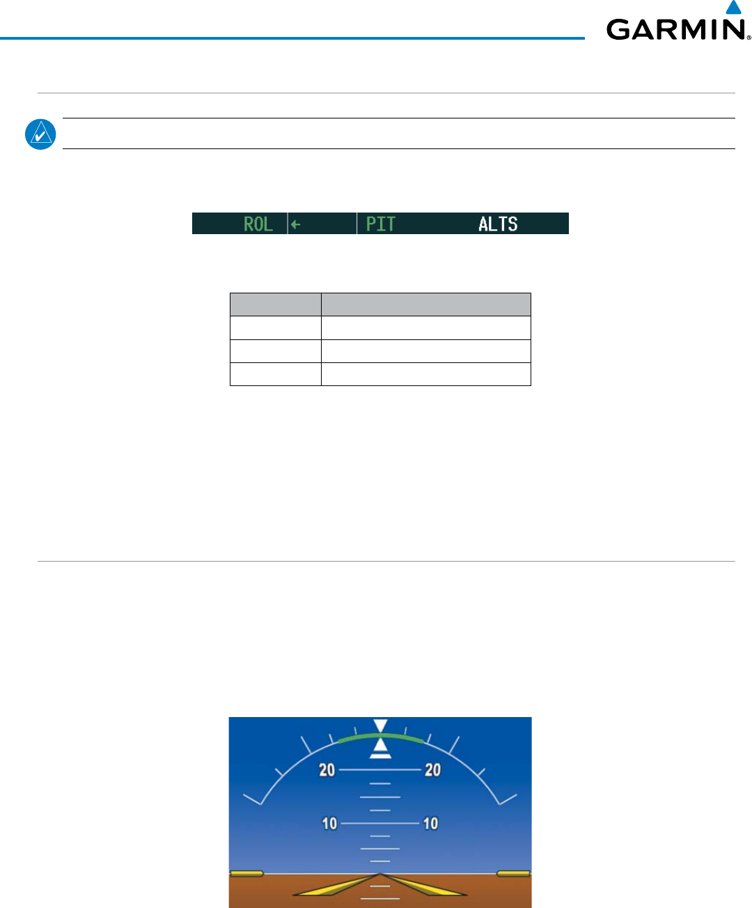
Garmin G1000 Pilot’s Guide for the Beechcraft 200/B200 Series
190-00928-04 Rev. A
516
AUTOMATIC FLIGHT CONTROL SYSTEM
ROLL HOLD MODE (ROL)
NOTE: If Roll Hold Mode is activated as a result of a mode reversion, the flight director rolls the wings level.
When the flight director is activated or switched, Roll Hold Mode is selected by default. This mode is annunciated
as ‘ROL’ in the AFCS Status Box. The current aircraft bank angle is held, subject to the bank angle condition.
Bank Angle Flight Director Response
< 6° Rolls wings level
6 to 25° Maintains current aircraft roll attitude
> 25° Limits bank to 25°
Table 7-4 Roll Hold Mode Responses
Figure 7-28 Roll Hold Mode Annunciation
CHANGING THE ROLL REFERENCE
The roll reference can be changed by pressing the
CWS
Button, establishing the desired bank angle, then releasing
the
CWS
Button.
LOW BANK MODE
When in Low Bank Mode, the flight director limits the maximum commanded roll angle to 15°. Low bank arc
limits are displayed in green along the Roll Scale.
Low Bank Mode can be manually selected/deselected by pressing the BANK Key while in Heading Select or
Navigation Modes (GPS and VOR). Low Bank Mode is activated automatically above 20,500 feet. The flight director
deactivates Low Bank Mode when descending through 20,500 feet. The annunciator light next to the BANK Key
illuminates while Low Bank Mode is selected.
Figure 7-29 Low Bank Mode Limits
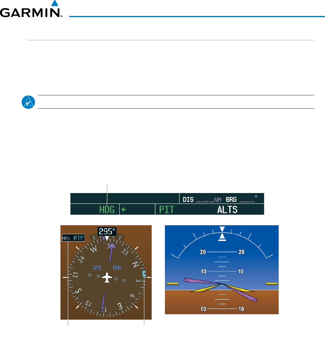
190-00928-04 Rev. A
Garmin G1000 Pilot’s Guide for the Beechcraft 200/B200 Series
517
AUTOMATIC FLIGHT CONTROL SYSTEM
HEADING SELECT MODE (HDG)
Heading Select Mode is activated by pressing the HDG Key. Heading Select Mode acquires and maintains the
Selected Heading. The Selected Heading is shown by a light blue bug on the HSI and in the box to the upper
left of the HSI.
CHANGING THE SELECTED HEADING
NOTE: Pressing the HDG Knob synchronizes the Selected Heading to the current heading.
The Selected Heading is adjusted using the HDG Knob on either PFD. Pressing the CWS Button and hand-
flying the aircraft does not change the Selected Heading. The autopilot guides the aircraft back to the Selected
Heading upon release of the CWS Button.
Turns are commanded in the same direction as Selected Heading Bug movement, even if the bug is turned
more than 180° from the present heading (e.g., a 270° turn to the right). However, Selected Heading changes
of more than 330° at a time result in turn reversals.
Figure 7-30 Heading Select Mode
Heading Select
Mode Active
Command Bars Track
Selected Heading
Selected
Heading Selected
Heading
Bug
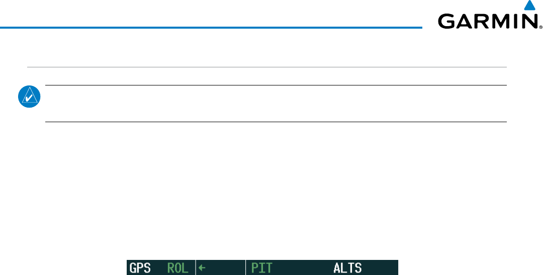
Garmin G1000 Pilot’s Guide for the Beechcraft 200/B200 Series
190-00928-04 Rev. A
518
AUTOMATIC FLIGHT CONTROL SYSTEM
NAVIGATION MODES (GPS, VOR, LOC)
NOTE: The selected navigation receiver must have a valid VOR or LOC signal or active GPS course for the
flight director to enter Navigation Mode.
Pressing the NAV Key selects Navigation Mode. Navigation Mode acquires and tracks the selected navigation
source (GPS, VOR, LOC). The flight director follows GPS roll steering commands when GPS is the selected
navigation source. When the navigation source is VOR or LOC, the flight director creates roll steering commands
from the Selected Course and deviation. Navigation Mode can also be used to fly non-precision GPS and LOC
approaches where vertical guidance is not required.
If the Course Deviation Indicator (CDI) shows greater than one dot when the NAV Key is pressed, the selected
mode is armed. If the CDI shows less than one dot, Navigation Mode is automatically captured when the NAV
Key is pressed. The armed annunciation appears in white to the left of the active lateral mode.
Figure 7-31 GPS Navigation Mode Armed
When the CDI has automatically switched from GPS to LOC during a LOC/ILS approach, GPS Navigation
Mode remains active, providing GPS steering guidance until the localizer signal is captured. LOC Navigation
Mode is armed automatically when the navigation source switch takes place if the APR Key is not pressed prior
to the automatic source switch.
If Navigation Mode is active and either of the following occur, the flight director reverts to Roll Hold Mode
(wings rolled level):
• Different VOR tuned while in VOR Navigation Mode (VOR Navigation Mode reverts to armed)
• Navigation source manually switched (with the CDI Softkey)
• During a LOC/ILS approach, the FAF is crossed while in GPS Navigation Mode after the automatic navigation
source switch from GPS to LOC
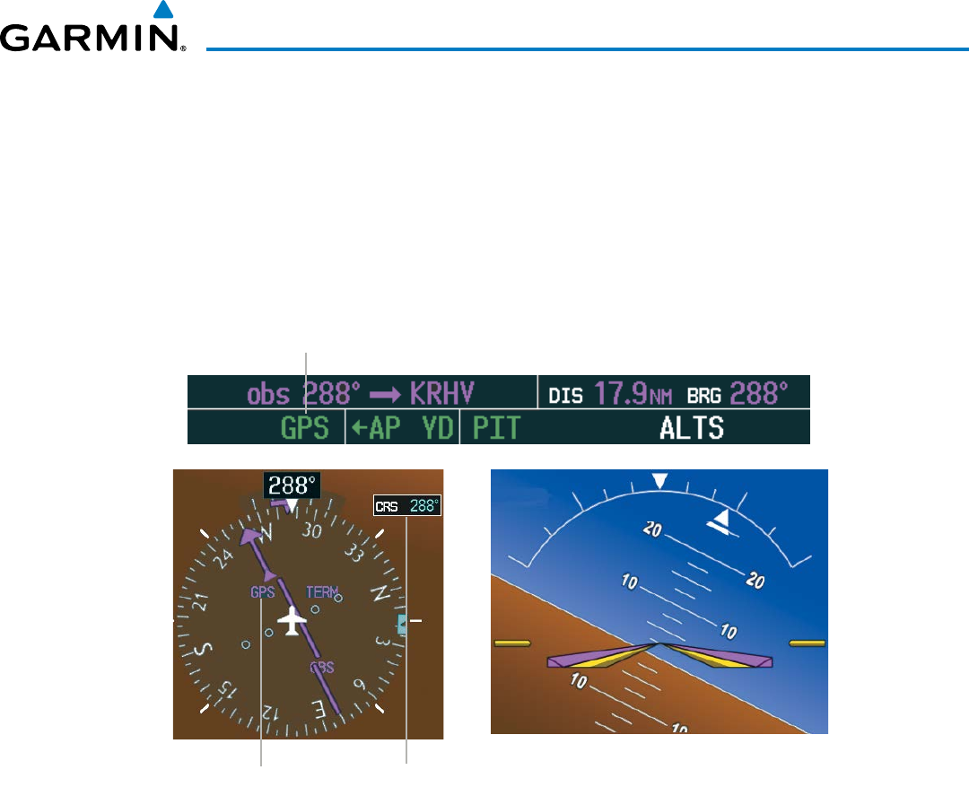
190-00928-04 Rev. A
Garmin G1000 Pilot’s Guide for the Beechcraft 200/B200 Series
519
AUTOMATIC FLIGHT CONTROL SYSTEM
CHANGING THE SELECTED COURSE
If the navigation source is VOR or localizer or OBS Mode has been enabled when using GPS, the Selected
Course is controlled using the CRS Knob corresponding to the selected flight director (CRS1 for the pilot
side, CRS2 for the copilot side).
Pressing the CWS Button and hand-flying the aircraft does not change the Selected Course while in
Navigation Mode. The autopilot guides the aircraft back to the Selected Course (or GPS flight plan) when the
CWS Button is released.
Figure 7-32 Navigation Mode
GPS Navigation
Mode Active
Command Bars Indicate Left
Turn to Track GPS Course
GPS is Selected
Navigation Source Selected
Course
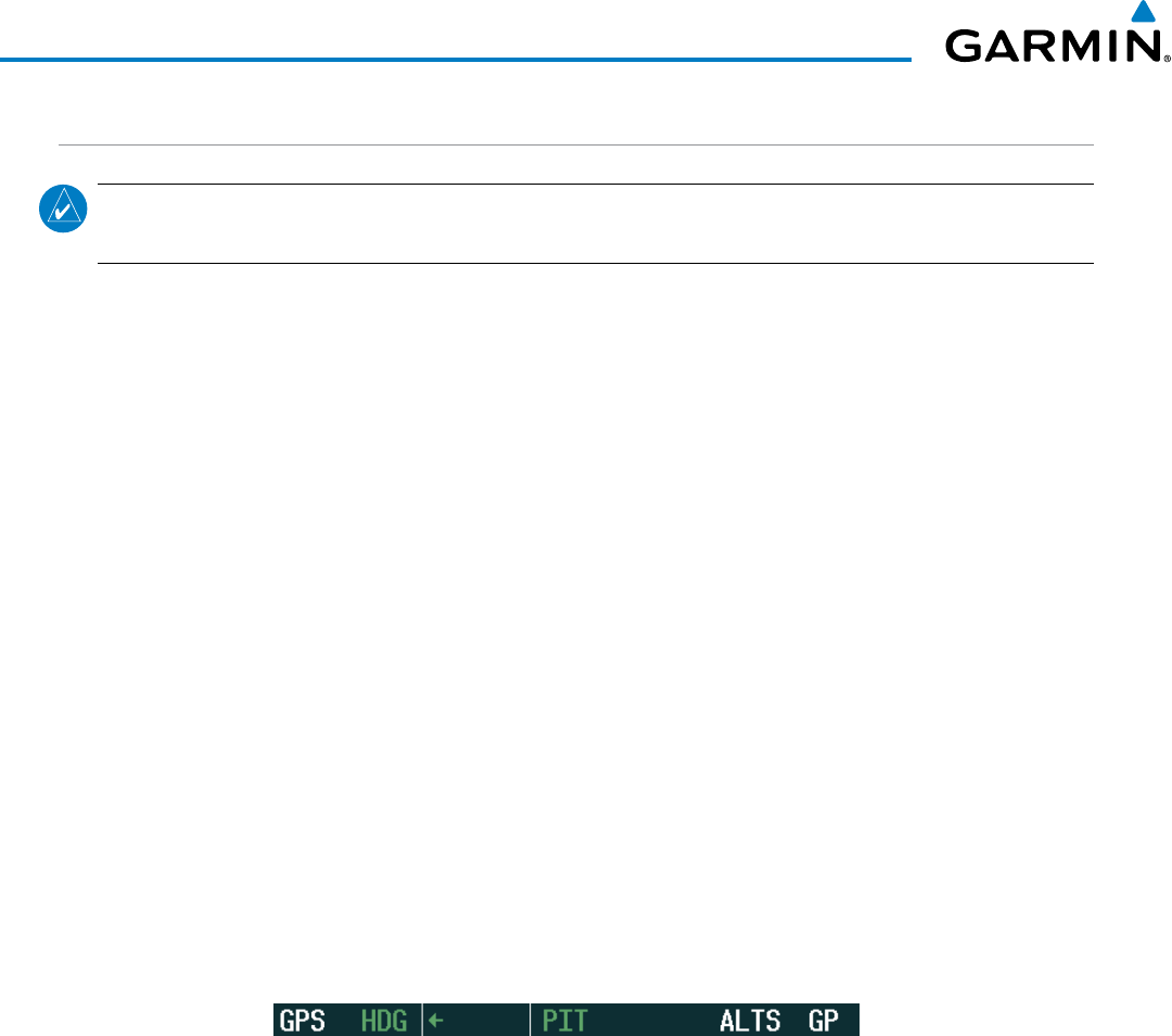
Garmin G1000 Pilot’s Guide for the Beechcraft 200/B200 Series
190-00928-04 Rev. A
520
AUTOMATIC FLIGHT CONTROL SYSTEM
APPROACH MODES (GPS, VAPP, LOC)
NOTE: The selected navigation receiver must have a valid VOR or LOC signal or active GPS course for the
flight director to enter Approach Mode.
Approach Mode is activated when the APR Key is pressed. Approach Mode acquires and tracks the selected
navigation source (GPS, VOR, or LOC), depending on loaded approach. This mode uses the selected navigation
receiver deviation and desired course inputs to fly the approach. Pressing the APR Key when the CDI is greater
than one dot arms the selected approach mode (annunciated in white to the left of the active lateral mode). If
the CDI is less the 1 dot, the LOC is automatically captured when the APR Key is pressed.
VOR Approach Mode (VAPP) provides greater sensitivity for signal tracking than VOR Navigation Mode.
Selecting VOR Approach Mode:
1) Ensure a valid VOR frequency is tuned
2) Ensure that VOR is the selected navigation source (use the CDI Softkey to cycle through navigation sources if
necessary).
3) Press the APR Key.
When GPS Approach Mode is armed, Glidepath Mode is also armed.
Selecting GPS Approach Mode:
1) Ensure a GPS approach is loaded into the active flight plan. The active waypoint must be part of the flight plan
(cannot be a direct-to a waypoint not in the flight plan).
2) Ensure that GPS is the selected navigation source (use the CDI Softkey to cycle through navigation sources if
necessary).
3) Press the APR Key.
Figure 7-33 GPS Approach Mode Armed

190-00928-04 Rev. A
Garmin G1000 Pilot’s Guide for the Beechcraft 200/B200 Series
521
AUTOMATIC FLIGHT CONTROL SYSTEM
LOC Approach Mode allows the autopilot to fly a LOC/ILS approach with a glideslope. When LOC Approach
Mode is armed, Glideslope Mode is also armed automatically. LOC captures are inhibited if the difference
between aircraft heading and localizer course exceeds 105°.
Selecting LOC Approach Mode:
1) Ensure a valid localizer frequency is tuned.
2) Ensure that LOC is the selected navigation source (use the CDI Softkey to cycle through navigation sources if
necessary).
3) Press the APR Key.
Or:
1) Ensure that GPS is the selected navigation source (use the CDI Softkey to cycle through navigation sources if
necessary).
2) Ensure a LOC/ILS approach is loaded into the active flight plan.
3) Ensure the corresponding LOC frequency is tuned.
4) Press the APR Key.
If the following occurs, the flight director reverts to Roll Hold Mode (wings rolled level):
• Approach Mode is active and a Vectors-To-Final is activated
• Approach Mode is active and Navigation source is manually switched
• During a LOC/ILS approach, GPS Navigation Mode is active and the FAF is crossed after the automatic
navigation source switch from GPS to LOC
CHANGING THE SELECTED COURSE
If the navigation source is VOR or localizer or OBS Mode has been enabled when using GPS, the Selected
Course is controlled using the CRS Knob corresponding to the selected flight director (CRS1 for the pilot
side, CRS2 for the copilot side).
Pressing the CWS Button and hand-flying the aircraft does not change the Selected Course while in
Approach Mode. The autopilot guides the aircraft back to the Selected Course (or GPS flight plan) when the
CWS Button is released.
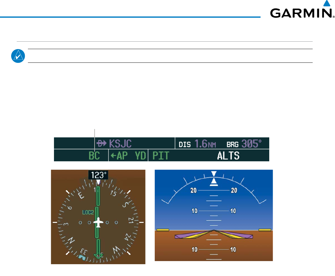
Garmin G1000 Pilot’s Guide for the Beechcraft 200/B200 Series
190-00928-04 Rev. A
522
AUTOMATIC FLIGHT CONTROL SYSTEM
BACKCOURSE MODE (BC)
NOTE: When making a backcourse approach, set the Selected Course to the localizer front course.
Backcourse Mode captures and tracks a localizer signal in the backcourse direction. The mode may be
selected by pressing the BC Key. Backcourse Mode is armed if the CDI is greater than one dot when the mode
is selected. If the CDI is less than one dot, Backcourse Mode is automatically captured when the BC Key is
pressed. The flight director creates roll steering commands from the Selected Course and deviation when in
Backcourse Mode.
Figure 7-34 Backcourse Mode
Backcourse
Mode Active
LOC2 is Selected Navigation Source Command Bars Hold Pitch Attitude
CHANGING THE SELECTED COURSE
If the navigation source is VOR or localizer or OBS Mode has been enabled when using GPS, the Selected
Course is controlled using the CRS Knob corresponding to the selected flight director (CRS1 for the pilot
side, CRS2 for the copilot side).
Pressing the CWS Button and hand-flying the aircraft does not reset any reference data while in Backcourse
Mode. The autopilot guides the aircraft back to the Selected Course when the CWS Button is released.
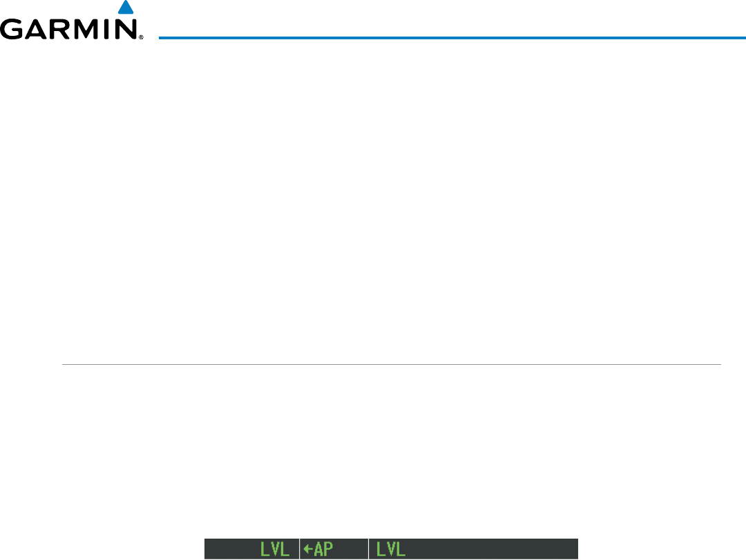
190-00928-04 Rev. A
Garmin G1000 Pilot’s Guide for the Beechcraft 200/B200 Series
523
AUTOMATIC FLIGHT CONTROL SYSTEM
INTERCEPTING AND FLYING A DME ARC
The AFCS will intercept and track a DME arc that is part of the active flight plan provided that GPS
Navigation Mode is engaged, GPS is the active navigation source on the CDI, and the DME arc segment is
the active flight plan leg. It is important to note that automatic navigation of DME arcs is based on GPS.
Thus, even if the APR key is pressed and LOC or VOR Approach Mode is armed prior to reaching the Initial
Approach Fix (IAF), Approach Mode will not activate until the arc segment is completed.
If the pilot decides to intercept the arc at a location other than the published IAF (i.e. ATC provides vectors
to intercept the arc) and subsequently selects Heading Mode or Roll Mode, the AFCS will not automatically
intercept or track the arc unless the pilot activates the arc leg of the flight plan and arms GPS Navigation
Mode. The AFCS will not intercept and fly a DME arc before reaching an IAF that defines the beginning of the
arc segment. Likewise, if at any point while established on the DME arc the pilot deselects GPS Navigation
Mode, the AFCS will no longer track the arc.
LEVEL MODE (LVL)
Level (LVL) mode becomes active only as a function of Electronic Stability and Protection (ESP). Refer to the
Additional Features section for a detailed discussion of the optional ESP feature.
When the normal flight envelope thresholds have been exceeded for more than 50% of the last 20 seconds,
Level mode is activated. The autopilot will engage and provide input to bring the aircraft back into straight
and level flight based on zero degrees roll angle and zero feet per minute vertical speed. An aural “ENGAGING
AUTOPILOT” alert sounds and the lateral and vertical flight director annunciations will display “LVL”. The
AFCS will remain in Level mode until the pilot selects another mode.
Figure 7-35 Level Mode
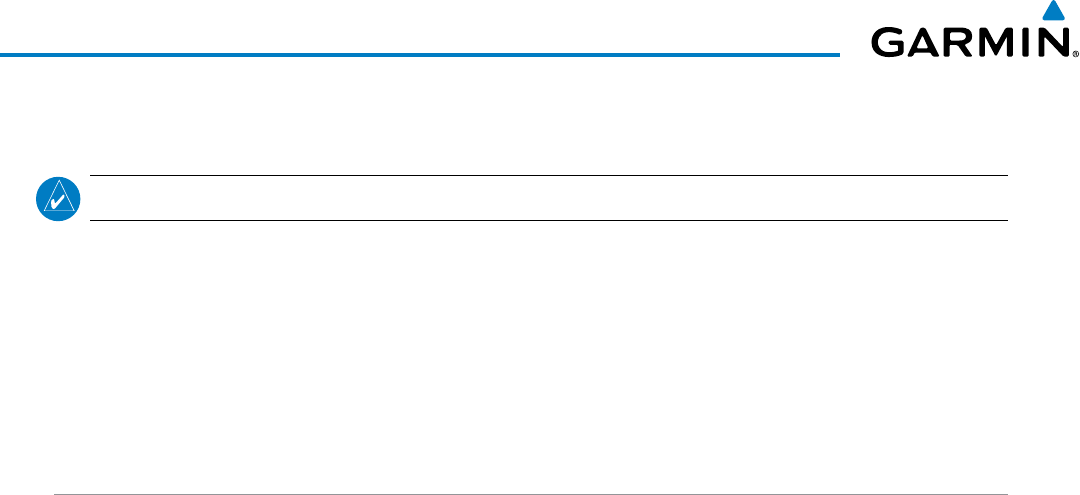
Garmin G1000 Pilot’s Guide for the Beechcraft 200/B200 Series
190-00928-04 Rev. A
524
AUTOMATIC FLIGHT CONTROL SYSTEM
7.5 AUTOPILOT AND YAW DAMPER OPERATION
NOTE: Refer to the POH/AFM for specific instructions regarding emergency procedures.
The autopilot and yaw damper operate the flight control surface servos to provide automatic flight control. The
autopilot controls the aircraft pitch and roll attitudes following commands received from the flight director. Pitch
autotrim provides trim commands to the pitch trim servo to relieve any sustained effort required by the pitch
servo. Autopilot operation is independent of the yaw damper.
The yaw damper reduces Dutch roll tendencies and coordinates turns. It can operate independently of the
autopilot and may be used during normal hand-flight maneuvers. Yaw rate commands are limited to 6 deg/sec
by the yaw damper.
FLIGHT CONTROL
Pitch and roll commands are provided to the servos based on the active flight director modes. Yaw damping
is provided by the yaw servo. Servo motor control limits the maximum servo speed and torque. The servo
gearboxes are equipped with slip-clutches set to certain values. This allows the servos to be overridden in case
of an emergency.
PITCH AXIS AND TRIM
The autopilot pitch axis uses pitch rate to stabilize the aircraft pitch attitude during flight director maneuvers.
Flight director pitch commands are rate- and attitude-limited, combined with pitch damper control, and sent
to the pitch servo motor. The pitch servo measures the output effort (torque) and provides this signal to the
pitch trim servo. The pitch trim servo commands the motor to reduce the average pitch servo effort.
When the autopilot is not engaged, the pitch trim servo may be used to provide manual electric pitch
trim (MEPT). This allows the aircraft to be trimmed using a control wheel switch rather than the trim
wheel. Manual trim commands are generated only when both halves of the MEPT Switch are operated
simultaneously. Trim speeds are scheduled with airspeed to provide more consistent response.
The pilot side MEPT Switch has priority over the copilot side MEPT Switch.
ROLL AXIS
The autopilot roll axis uses roll rate to stabilize aircraft roll attitude during flight director maneuvers. The
flight director roll commands are rate- and attitude-limited, combined with roll damper control, and sent to
the roll servo motor.
YAW AXIS
The yaw damper uses yaw rate and roll attitude to dampen the aircraft’s natural Dutch roll response. It also
uses lateral acceleration to coordinate turns.
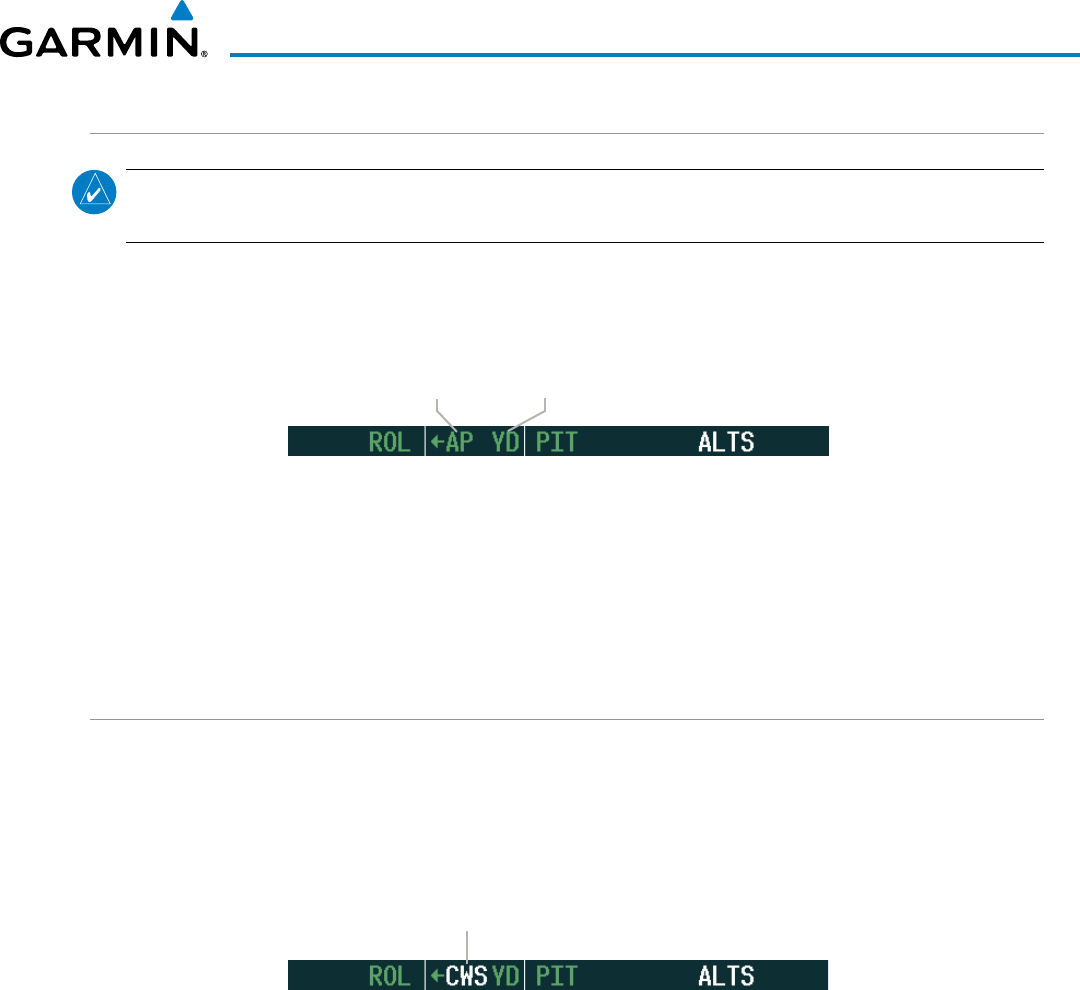
190-00928-04 Rev. A
Garmin G1000 Pilot’s Guide for the Beechcraft 200/B200 Series
525
AUTOMATIC FLIGHT CONTROL SYSTEM
ENGAGEMENT
NOTE: Autopilot engagement/disengagement is not equivalent to servo engagement/disengagement. Use
the CWS Button to disengage the pitch and roll servos while the autopilot remains active.
When the
AP
Key is pressed, the autopilot, yaw damper, and flight director (if not already active) are activated
and the annunciator lights on the AFCS controller for the autopilot and yaw damper are illuminated. The flight
director engages in Pitch and Roll Hold Modes when initially activated.
Figure 7-36 Autopilot and Yaw Damper Engaged
Autopilot
Engaged Yaw Damper
Engaged
When the YD Key is pressed, the system engages the yaw damper independently of the autopilot and the yaw
damper annunciator light is illuminated.
Autopilot and yaw damper status are displayed in the center of the AFCS Status Box. Engagement is indicated
by green ‘AP’ and ‘YD’ annunciations, respectively.
CONTROL WHEEL STEERING
During autopilot operation, the aircraft may be hand-flown without disengaging the autopilot. Pressing and
holding the
CWS
Button disengages the pitch and roll servos from the flight control surfaces and allows the
aircraft to be hand-flown. At the same time, the flight director is synchronized to the aircraft attitude during
the maneuver. CWS activity has no effect on yaw damper engagement.
The ‘AP’ annunciation is temporarily replaced by ‘CWS’ in white for the duration of CWS maneuvers.
Figure 7-37 CWS Annunciation
Control Wheel Steering
In most scenarios, releasing the
CWS
Button reengages the autopilot with a new reference. Refer to flight
director mode descriptions for specific CWS behavior in each mode.
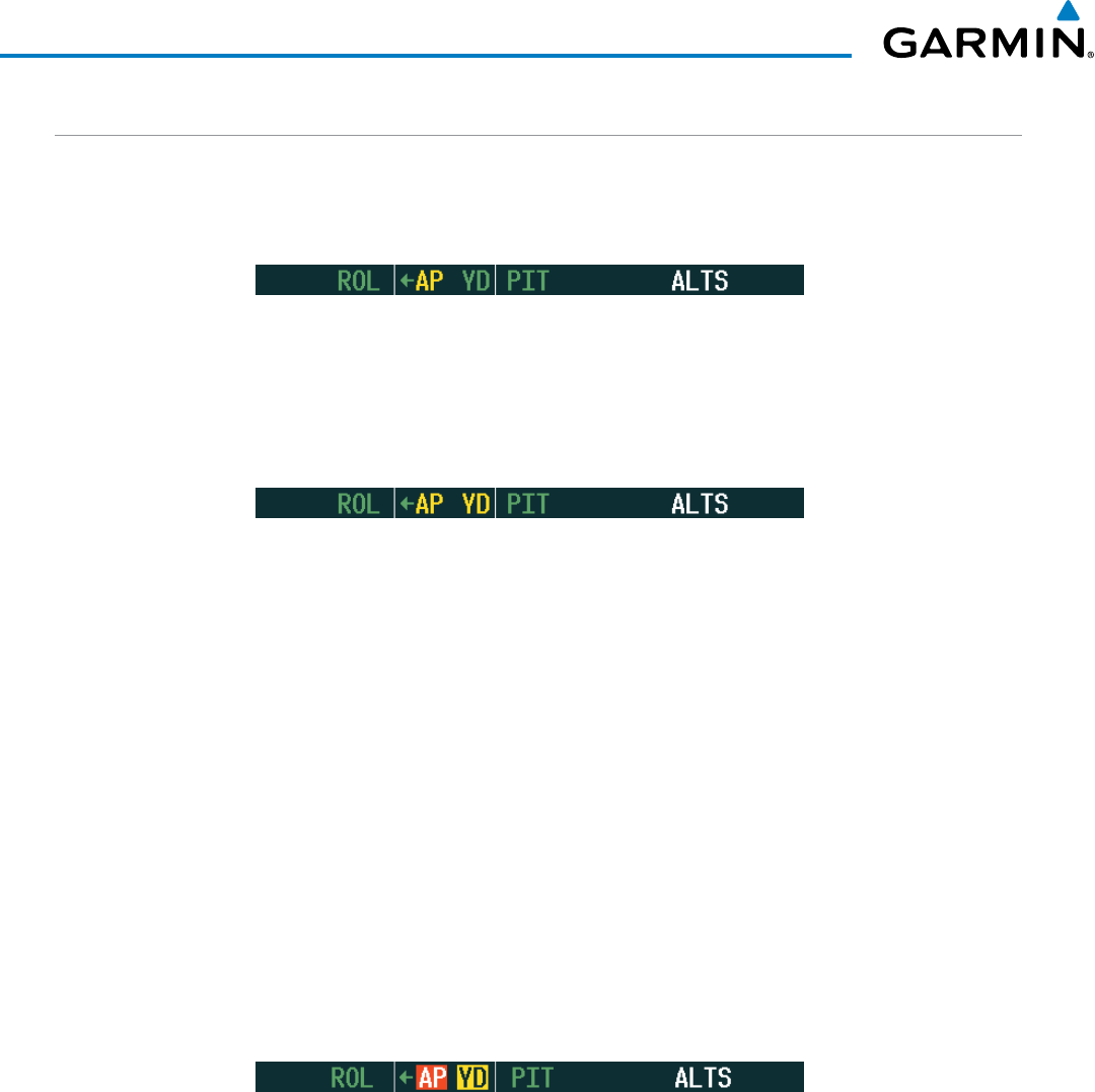
Garmin G1000 Pilot’s Guide for the Beechcraft 200/B200 Series
190-00928-04 Rev. A
526
AUTOMATIC FLIGHT CONTROL SYSTEM
DISENGAGEMENT
The autopilot is manually disengaged by pushing the
AP
Key on the AFCS Control Unit or the
MEPT ARM
Switch. Manual autopilot disengagement is indicated by a five-second flashing yellow ‘AP’ annunciation and a
three-second autopilot disconnect aural alert.
Figure 7-38 Manual Autopilot Disengagement
Pushing the
AP/YD DISC
Switch disengages both the yaw damper and the autopilot. When the yaw damper
and autopilot are manually disengaged, both the ‘AP’ and ‘YD’ annunciation turn yellow and flash for 5 seconds
and a three-second autopilot disconnect aural alert is generated.
Figure 7-39 Yaw Damper Disengagement
After manual disengagement, the autopilot disconnect aural alert may be cancelled by pushing the MEPT ARM
or
AP/YD DISC
Switch (
AP/YD DISC
Switch also cancels the flashing ‘AP’ annunciation).
Automatic autopilot disengagement is indicated by a flashing red and white ‘AP’ annunciation and by the
autopilot disconnect aural alert, which continue until acknowledged by pushing the AP/YD DISC or
MEPT ARM
Switch. Automatic autopilot disengagement occurs due to:
• System failure
• Invalid sensor data
• Inability to compute default flight director modes (FD also disengages automatically)
Yaw damper disengagement is indicated by a five-second flashing yellow ‘YD’ annunciation. Automatic yaw
damper disengagement occurs when autopilot disengagement is caused by failure in a parameter also affecting
the yaw damper. This means the yaw damper can remain operational in some cases where the autopilot
automatically disengages. A localized failure in the yaw damper system or invalid sensor data also cause yaw
damper disengagement.
Figure 7-40 Automatic Autopilot and Yaw Damper Disengagement
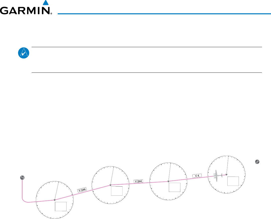
190-00928-04 Rev. A
Garmin G1000 Pilot’s Guide for the Beechcraft 200/B200 Series
527
AUTOMATIC FLIGHT CONTROL SYSTEM
7.6 EXAMPLE FLIGHT PLAN
NOTE: The following example flight plan and diagrams (not to be used for navigation) in this section are
for instructional purposes only and should be considered not current. Numbered portions of accompanying
diagrams correspond to numbered procedure steps.
This scenario-based set of procedures (based on the example flight plan found in the Flight Management
Section) shows various GFC 700 AFCS modes used during a flight. In this scenario, the aircraft departs Charles
B. Wheeler Downtown Airport (KMKC), enroute to Colorado Springs Airport (KCOS). After departure, the
aircraft climbs to 12,000 ft and airway V4 is intercepted, following ATC vectors.
Airway V4 is flown to Salina VOR (SLN) using VOR navigation, then airway V244 is flown using GPS Navigation.
The ILS approach for runway 35L and LPV (WAAS) approach for runway 35R are shown and a missed approach
is executed.
Figure 7-41 Flight Plan Overview
0
3
6
9
12
15
18
21
24
27
30
33
0
3
6
9
12
15
18
21
24
27
30
33
Salina
VOR
(SLN)
KMKC
Lamar
VOR
(LAA)
0
3
6
9
12
15
18
21
24
27
30
33
Hays
VOR
(HYS)
KCOS
V 244
V 4
V 244
0
3
6
9
12
15
18
21
24
27
30
33
Topeka
VOR
(TOP)
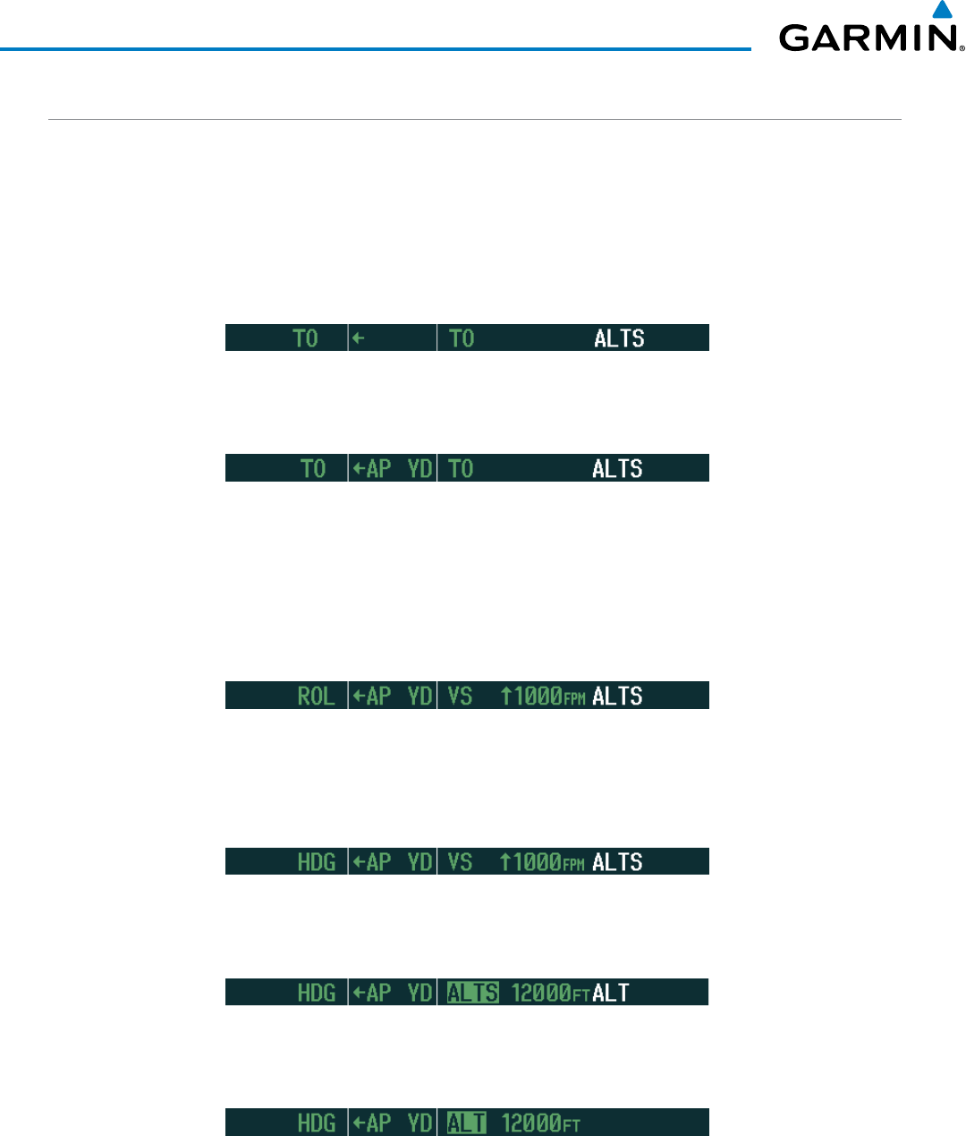
Garmin G1000 Pilot’s Guide for the Beechcraft 200/B200 Series
190-00928-04 Rev. A
528
AUTOMATIC FLIGHT CONTROL SYSTEM
DEPARTURE
Climbing to the Selected Altitude and flying an assigned heading:
1) Before takeoff:
a) Use the ALT SEL Knob to set the Selected Altitude to 12,000 feet.
b) Push the GA Button to activate Takeoff Mode. The flight director Command Bars establish a pitch up attitude
to follow.
c) Press the
AP
Key to engage the autopilot in a climb, holding the pitch angle commanded in Takeoff Mode and
wings level.
2) In this example, Vertical Speed Mode is used to capture the Selected Altitude (Pitch Hold, Vertical Speed, or
Flight Level Change Mode may be used).
Press the VS Key to activate Vertical Speed Mode.
The Vertical Speed Reference may be adjusted after Vertical Speed Mode is selected using the NOSE UP/DN
Wheel or pushing the CWS Button while hand-flying the aircraft to establish a new Vertical Speed Reference.
3) Use the
HDG
Knob to set the Selected Heading, complying with ATC vectors to intercept Airway V4.
Press the HDG Key to activate Heading Select Mode while the autopilot is engaged in the climb. The autopilot
follows the Selected Heading Bug on the HSI and turns the aircraft to the desired heading.
4) As the aircraft nears the Selected Altitude, the flight director transitions to Selected Altitude Capture Mode,
indicated by the green ‘ALTS’ annunciation flashing for up to 10 seconds.
At 50 feet from the Selected Altitude, the green ‘ALT’ annunciation flashes for up to 10 seconds; the autopilot
transitions to Altitude Hold Mode and levels the aircraft.
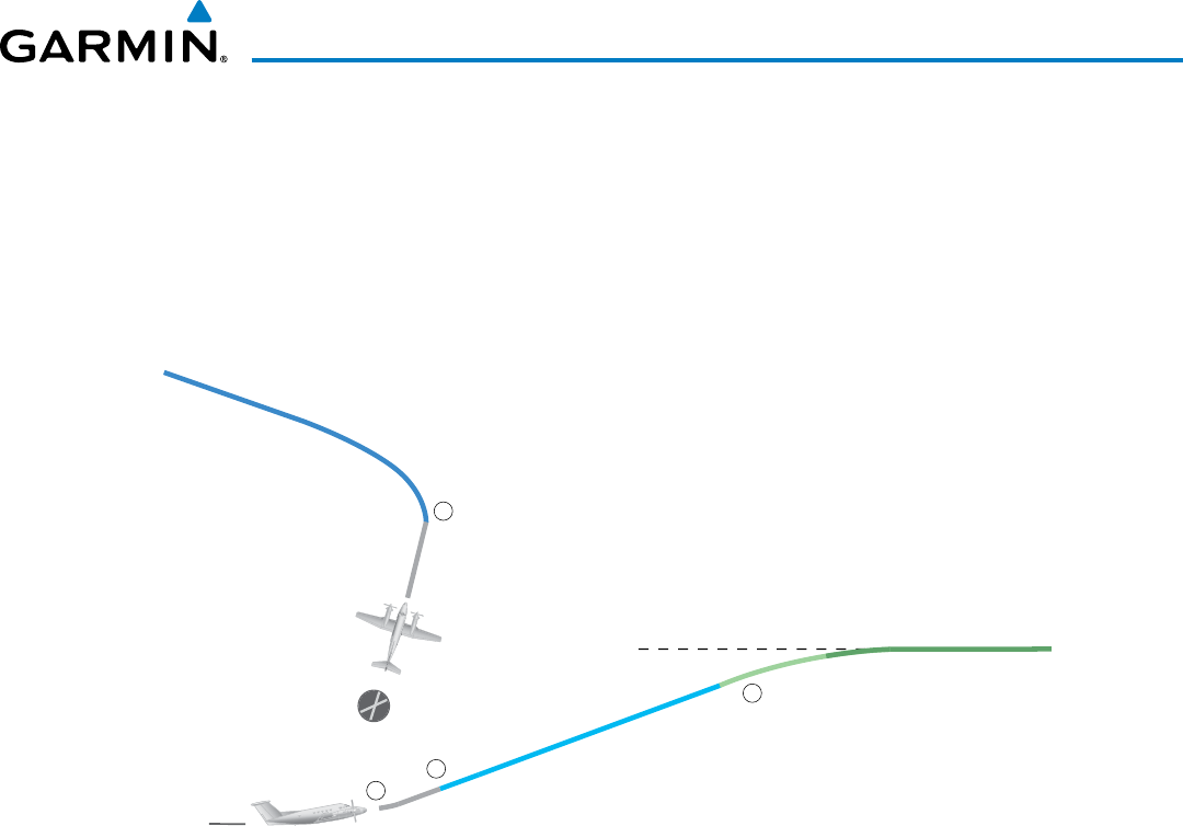
190-00928-04 Rev. A
Garmin G1000 Pilot’s Guide for the Beechcraft 200/B200 Series
529
AUTOMATIC FLIGHT CONTROL SYSTEM
Figure 7-42 Departure
Selected Altitude of 12,000 MSL
1
2
3
4
HDG Mode
VS Mode
ALT Mode
TO Mode
TO Mode
KMKC
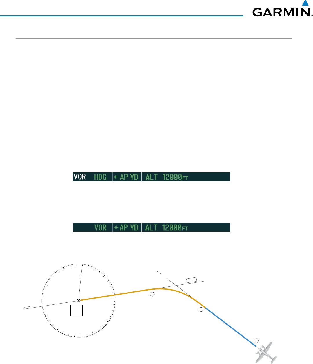
Garmin G1000 Pilot’s Guide for the Beechcraft 200/B200 Series
190-00928-04 Rev. A
530
AUTOMATIC FLIGHT CONTROL SYSTEM
INTERCEPTING A VOR RADIAL
During climb-out, the autopilot continues to fly the aircraft in Heading Select Mode. Airway V4 to Salina
VOR (SLN) should now be intercepted. Since the enroute flight plan waypoints correspond to VORs, flight
director Navigation Mode using either VOR or GPS as the navigation source may be used. In this scenario, VOR
Navigation Mode is used for navigation to the first VOR waypoint in the flight plan.
Intercepting a VOR radial:
1) Arm VOR Navigation Mode:
a) Tune the VOR frequency.
b) Press the CDI Softkey to set the navigation source to VOR.
c) Use the CRS1 or CRS2 Knob to set the Selected Course to the desired value, 255°. Note that at this point, the
flight director is still in Heading Select Mode and the autopilot continues to fly the Selected Heading, 290°.
d) Press the
NAV
Key. This arms VOR Navigation Mode and the white ‘VOR’ annunciation appears to the left of
the active lateral mode.
2) As the aircraft nears the Selected Course, the flight director transitions from Heading Select to VOR Navigation
Mode and the ‘VOR’ annunciation flashes green. The autopilot begins turning to intercept the Selected
Course.
3) The autopilot continues the turn until the aircraft is established on the Selected Course.
Figure 7-43 Intercepting a VOR Radial
0
3
6
9
12
15
18
21
24
27
30
33
HDG Mode, VOR Armed
VOR NAV Mode
V 4
Salina
VOR
(SLN)
1
2
3
Hdg
290
o
255
o
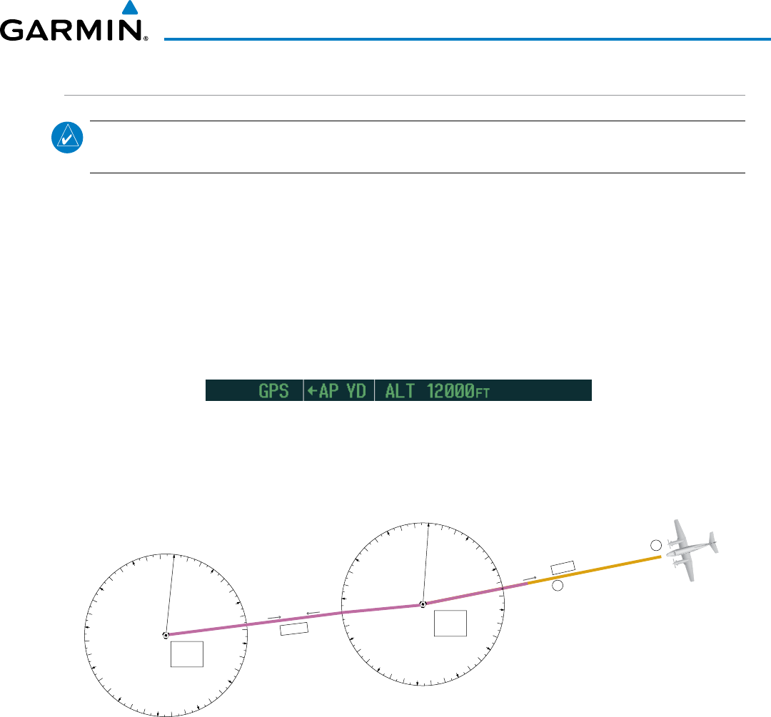
190-00928-04 Rev. A
Garmin G1000 Pilot’s Guide for the Beechcraft 200/B200 Series
531
AUTOMATIC FLIGHT CONTROL SYSTEM
FLYING A FLIGHT PLAN/GPS COURSE
NOTE: Changing the navigation source cancels Navigation Mode and causes the flight director to revert
back to Roll Hold Mode (wings rolled level).
As the aircraft closes on Salina VOR, GPS is used to navigate the next leg, airway V244. The aircraft is
currently tracking inbound on Airway V4.
Flying a GPS flight plan:
1) Transition from VOR to GPS Navigation Mode:
a) Press the
CDI
Softkey until GPS is the selected navigation source.
b) Press the
NAV
Key to activate GPS Navigation Mode. The autopilot guides the aircraft along the active flight
plan leg.
2) Following the flight plan, the autopilot continues to steer the aircraft under GPS guidance. Note that in GPS
Navigation Mode, course changes defined by the flight plan are automatically made without pilot action
required.
Figure 7-44 Transition to GPS Flight Plan
0
3
6
9
12
15
18
21
24
27
30
33
VOR NAV Mode
GPS NAV Mode
V 244
1
2
V 4
076
o
075
o
260
o
0
3
6
9
12
15
18
21
24
27
30
33
Salina
VOR
(SLN)
Hays
VOR
(HYS)

Garmin G1000 Pilot’s Guide for the Beechcraft 200/B200 Series
190-00928-04 Rev. A
532
AUTOMATIC FLIGHT CONTROL SYSTEM
DESCENT
While flying the arrival procedure, the aircraft is cleared for descent in preparation for the approach to KCOS.
Three methods are presented for descent:
• Flight Level Change descent – Flight Level Change Mode can be used to descend to the Selected Altitude at a
constant airspeed. This descent method does not account for flight plan waypoint altitude constraints.
• Vertical Path Tracking descent – Vertical Path Tracking Mode is used to follow the vertical descent path
defined in the GPS flight plan. Altitude constraints correspond to waypoints in the flight plan. Before VNV
flight control can provide vertical profile guidance, a VNV flight plan must be entered and enabled.
• Non-path descent in a VNV scenario – A VNV flight plan is entered and enabled, however Pitch Hold, Vertical
Speed, or Flight Level Change Mode can be used to descend to the VNV Target Altitude prior to reaching the
planned TOD. Flight Level Change Mode is used in the example.
Flight Level Change descent:
1) Select Flight Level Change Mode:
a) Using the ALT SEL Knob, set the Selected Altitude to 10,000 feet.
b) Press the
FLC
Key to activate Flight Level Change Mode. The annunciation ‘FLC’ appears next to the
Airspeed Reference, which defaults to the current aircraft airspeed. Selected Altitude Capture Mode is armed
automatically.
c) If desired press the SPD Key to display the Airspeed Reference in Mach.
2) Use the NOSE UP/DN Wheel or push the CWS Button while hand-flying the aircraft to adjust the commanded
airspeed while maintaining the same power, or reduce power to allow descent in Flight Level Change Mode
while the autopilot maintains the current airspeed.
3) As the aircraft nears the Selected Altitude, the flight director transitions to Selected Altitude Capture Mode,
indicated by the green ‘ALTS’ annunciation flashing for up to 10 seconds.
The green ‘ALT’ annunciation flashes for up to 10 seconds upon reaching 50 feet from the Selected Altitude; the
autopilot transitions to Altitude Hold Mode and levels the aircraft.
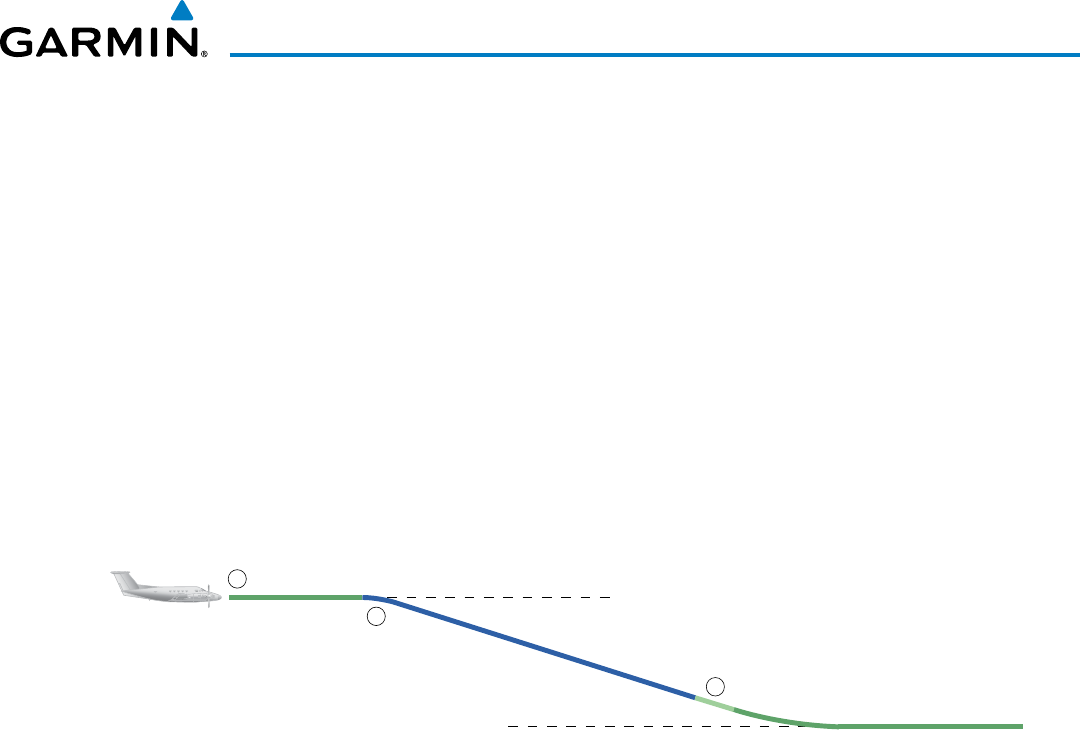
190-00928-04 Rev. A
Garmin G1000 Pilot’s Guide for the Beechcraft 200/B200 Series
533
AUTOMATIC FLIGHT CONTROL SYSTEM
Figure 7-45 FLC Descent
Cruise Altitude of 12,000 MSL
Selected Altitude of 10,000 MSL
ALT Mode
FLC Mode
ALT Mode
1
2
3

Garmin G1000 Pilot’s Guide for the Beechcraft 200/B200 Series
190-00928-04 Rev. A
534
AUTOMATIC FLIGHT CONTROL SYSTEM
Vertical Path Tracking descent to VNV Target Altitude:
1) Select VNV flight control:
a) Press the
VNV
Key to arm Vertical Path Tracking Mode. The white annunciation ‘VPTH’ appears.
b) Using the ALT SEL Knob, set the Selected Altitude below the flight plan’s VNV Target Altitude of 10,000 feet.
If the Selected Altitude is not at least 75 ft below the VNV Target Altitude, the flight director captures the
Selected Altitude rather than the VNV Target Altitude once Vertical Path Tracking Mode becomes active (ALTS is
armed rather than ALTV).
c) If Vertical Path Tracking Mode is armed more than 5 minutes prior to descent path capture, acknowledgment is
required for the flight director to transition from Altitude Hold to Vertical Path Tracking Mode. To proceed with
descent path capture if the white ‘VPTH’ annunciation begins flashing, do one of the following
• Press the VNV Key
• Turn the ALT SEL Knob to adjust the Selected Altitude
If the descent is not confirmed by the time of interception, Vertical Path Tracking Mode remains armed and the
descent is not captured.
2) When the top of descent (TOD) is reached, the flight director transitions to Vertical Path Tracking Mode and
begins the descent to the VNV Target Altitude. Intention to capture the VNV Target Altitude is indicated by the
white ‘ALTV’ annunciation.
3) As the aircraft nears the VNV Target Altitude, the flight director transitions to VNV Target Altitude Capture Mode,
indicated by the green ‘ALTV’ annunciation flashing for up to 10 seconds.
The green ‘ALT’ annunciation flashes for up to 10 seconds upon reaching 50 feet from the VNV Target Altitude;
the autopilot transitions to Altitude Hold Mode and levels the aircraft at the vertical waypoint.
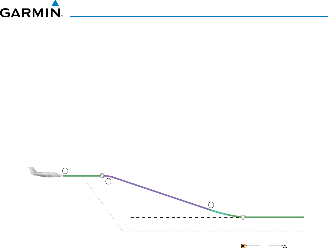
190-00928-04 Rev. A
Garmin G1000 Pilot’s Guide for the Beechcraft 200/B200 Series
535
AUTOMATIC FLIGHT CONTROL SYSTEM
Figure 7-46 VPTH Descent
Cruise Altitude of 12,000 MSL
VNAV Target Altitude of 10,000 MSL ALT Mode
VPTH Mode
Selected Altitude (set below VNAV Target Altitude)
1
2
3
TOD
BOD
ALT Mode
3 nm
Along-track Offset, 3 nm before OPSHN
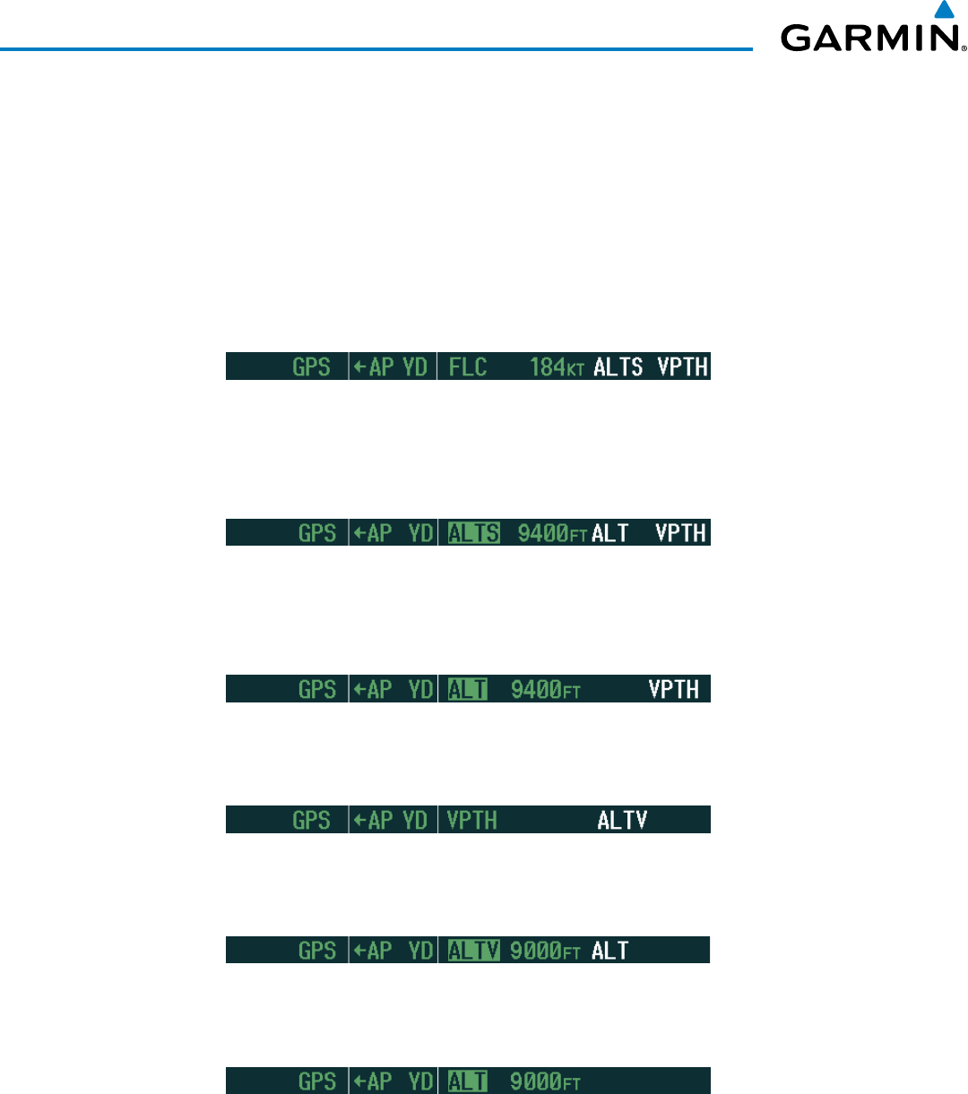
Garmin G1000 Pilot’s Guide for the Beechcraft 200/B200 Series
190-00928-04 Rev. A
536
AUTOMATIC FLIGHT CONTROL SYSTEM
Non-path descent using Flight Level Change Mode:
1) Using Flight Level Change Mode, command a non-path descent to an intermediate altitude above the next VNV
flight plan altitude.
a) Using the ALT SEL Knob, set the Selected Altitude below the current aircraft altitude to an altitude (in this case,
9,400 feet) at which to level off between VNV flight plan altitudes.
b) Press the FLC Key before the planned TOD during an altitude hold while VPTH is armed. The Airspeed Reference
defaults to the current aircraft airspeed. Vertical Path Tracking and Selected Altitude Capture Mode are armed
automatically.
2) Reduce power to allow descent in Flight Level Change Mode. The autopilot maintains the Airspeed Reference.
3) As the aircraft nears the Selected Altitude, the flight director transitions to Selected Altitude Capture Mode,
indicated by the green ‘ALTS’ annunciation flashing for up to 10 seconds.
The green ‘ALT’ annunciation flashes for up to 10 seconds upon reaching 50 feet from the Selected Altitude; the
autopilot transitions to Altitude Hold Mode and levels the aircraft. After leveling off reset Selected Altitude at
or below 9,000 ft.
4) When the next TOD is reached, Vertical Path Tracking becomes active (may require acknowledgment to allow
descent path capture).
5) As the aircraft nears the VNV Target Altitude, the flight director transitions to VNV Target Altitude Capture Mode,
indicated by the green ‘ALTV’ annunciation flashing for up to 10 seconds.
The green ‘ALT’ annunciation flashes for up to 10 seconds upon reaching 50 feet from the VNV Target Altitude;
the autopilot transitions to Altitude Hold Mode and levels the aircraft at the vertical waypoint.
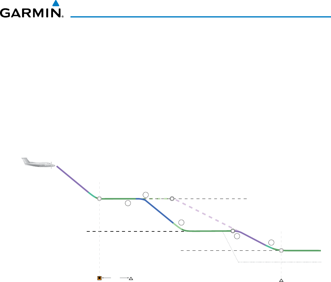
190-00928-04 Rev. A
Garmin G1000 Pilot’s Guide for the Beechcraft 200/B200 Series
537
AUTOMATIC FLIGHT CONTROL SYSTEM
Figure 7-47 Non-path Descent
HABUK
VNAV Target Altitude of 10,000 MSL
VNAV Target Altitude of 9,000 MSL ALT Mode
Planned Descent Path
Selected Altitude of 9,400 MSL
ALT Mode
VPTH Mode
1
2
3
FLC Mode
4
VPTH Mode
ALT Mode
Selected Altitude
5
TOD
Planned
TOD
BOD
BOD
OPSHN
3 nm
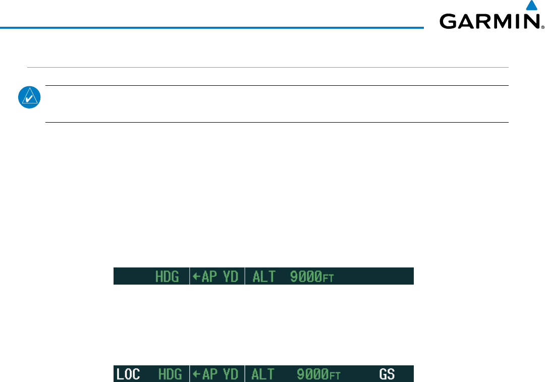
Garmin G1000 Pilot’s Guide for the Beechcraft 200/B200 Series
190-00928-04 Rev. A
538
AUTOMATIC FLIGHT CONTROL SYSTEM
APPROACH
NOTE: If an approach contains a DME arc, the arc must be flown in Navigation Mode with the GFC 700.
When receiving vectors from ATC, Navigation Mode must be selected prior to intercepting the ARC.
Flying an ILS approach:
1) Transition from GPS Navigation Mode to Heading Select Mode.
a) Select the Runway 35L ILS approach for KCOS and select ‘VECTORS’ for the transition. Load and activate the
approach into the flight plan.
b) Use the HDG Knob to set the Selected Heading after getting vectors from ATC.
c) Press the HDG Key. The autopilot turns the aircraft to the desired heading.
d) Use Heading Select Mode to comply with ATC vectors as requested.
2) Arm LOC Approach and Glideslope modes.
a) Ensure the appropriate localizer frequency is tuned.
b) Press the APR Key when cleared for approach to arm Approach and Glideslope modes. ‘LOC’ and ‘GS’ appear
in white as armed mode annunciations.
c)
The navigation source automatically switches to LOC. After this switch occurs, the localizer signal can be captured
and the flight director determines when to begin the turn to intercept the final approach course. The flight
director now provides guidance to the missed approach point.
3) There are two options available at this point, as the autopilot flies the ILS approach:
• Push the AP/YD DISC Switch at the decision height and land the aircraft.
• Use the
GA Button
to execute a missed approach.
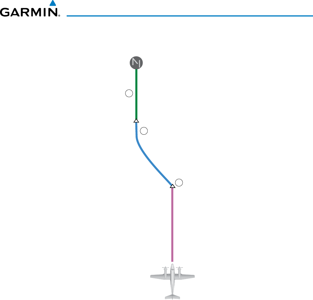
190-00928-04 Rev. A
Garmin G1000 Pilot’s Guide for the Beechcraft 200/B200 Series
539
AUTOMATIC FLIGHT CONTROL SYSTEM
Figure 7-48 ILS Approach to KCOS
HDG Mode
LOC APR/
GS Mode
PETEY
1
2
3
GPS NAV Mode
KCOS
PYNON
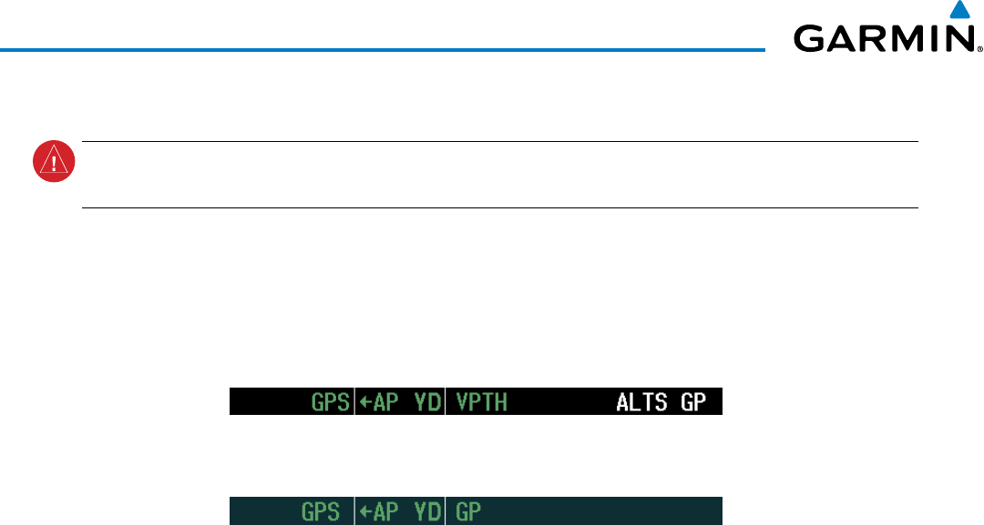
Garmin G1000 Pilot’s Guide for the Beechcraft 200/B200 Series
190-00928-04 Rev. A
540
AUTOMATIC FLIGHT CONTROL SYSTEM
Flying a RNAV GPS approach with vertical guidance:
WARNING: When flying an LNAV approach (with vertical guidance) with the autopilot coupled, the aircraft
will not level off at the MDA even if the MDA is set in the altitude preselect.
1) Arm flight director modes for a RNAV GPS approach with vertical guidance:
a) Make sure the navigation source is set to GPS (use CDI Softkey to change navigation source).
b) Select the Runway 35R LPV approach for KCOS. Load and activate the approach into the flight plan.
2) Press the APR Key once clearance for approach has been received. GPS Approach Mode is activated and
Glidepath Mode is armed.
3) Once the glidepath is captured, Glidepath Mode becomes active. The flight director now provides guidance to
the missed approach point.
4) There are two options available at this point, as the autopilot flies the approach:
• Push the AP/YD DISC Switch at the decision height and land the aircraft.
• Use the
GA Button
to execute a missed approach.
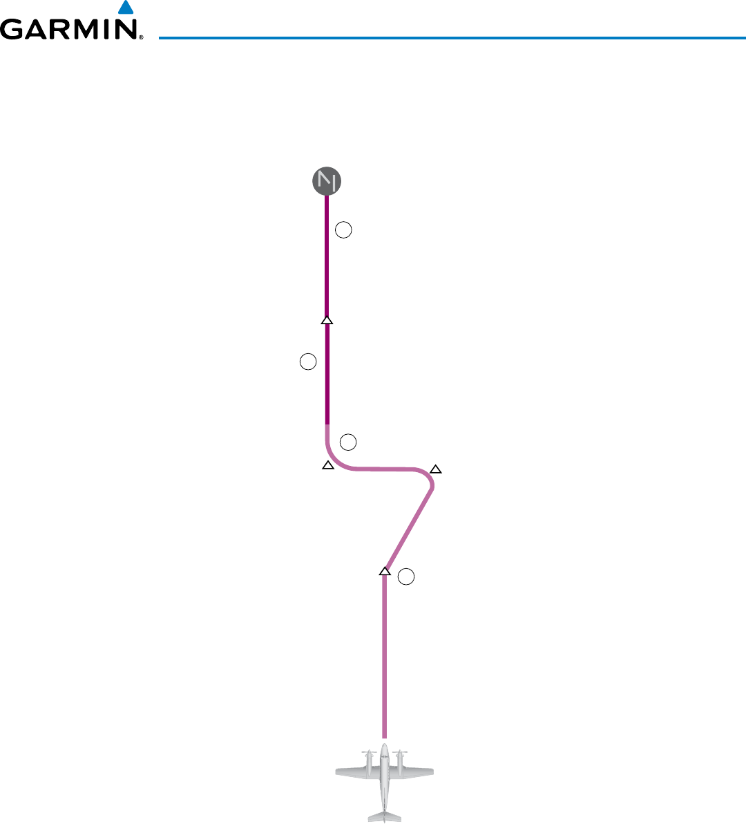
190-00928-04 Rev. A
Garmin G1000 Pilot’s Guide for the Beechcraft 200/B200 Series
541
AUTOMATIC FLIGHT CONTROL SYSTEM
4
GPS APR/
GP Mode
FALUR
1
2
3
GPS NAV Mode
KCOS
HABUK
PYNON
CEGIX
Figure 7-49 LPV Approach to KCOS
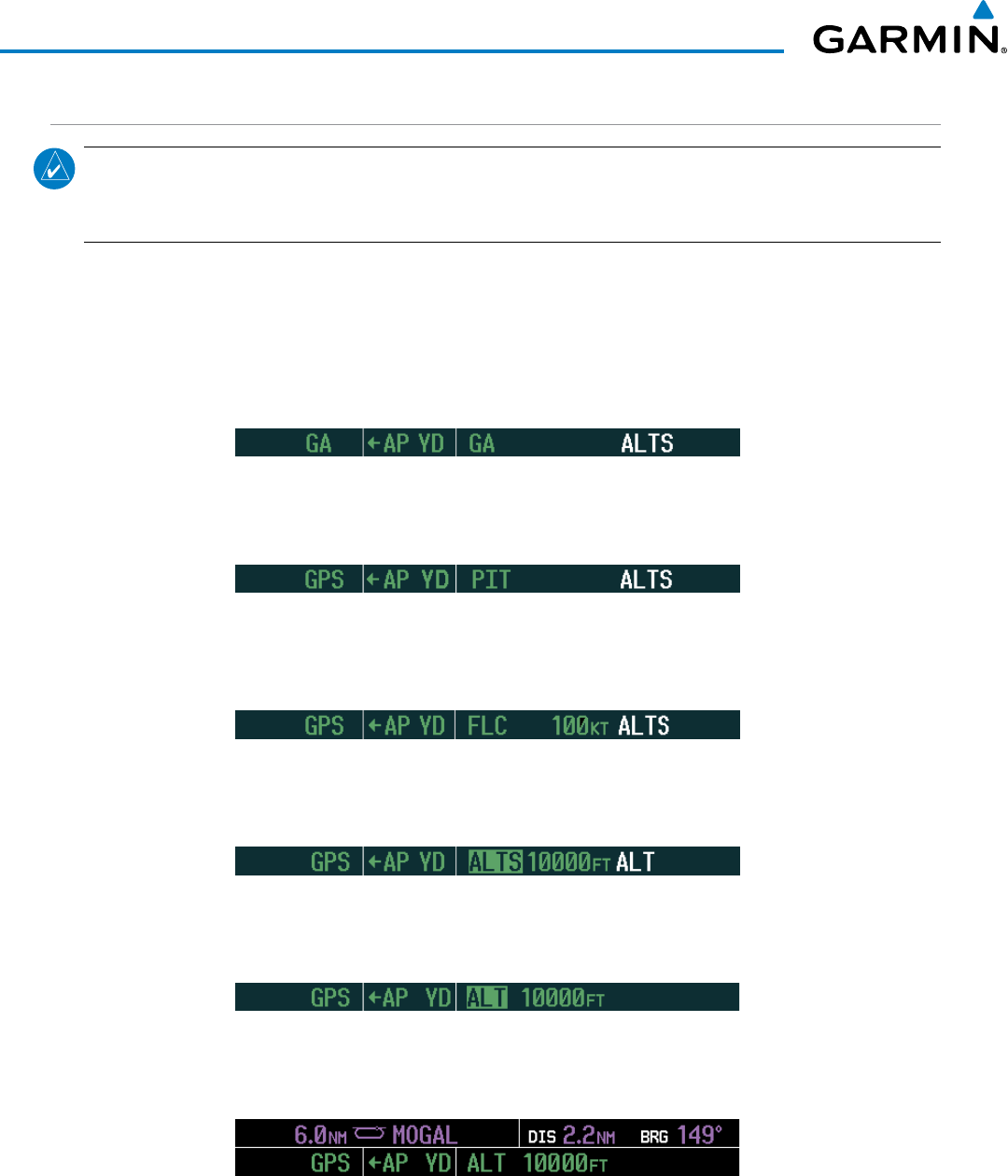
Garmin G1000 Pilot’s Guide for the Beechcraft 200/B200 Series
190-00928-04 Rev. A
542
AUTOMATIC FLIGHT CONTROL SYSTEM
GO AROUND/MISSED APPROACH
NOTE: As a result of calculations performed by the system while flying the holding pattern, the display may
re-size automatically and the aircraft may not precisely track the holding pattern as depicted on the PFD and
MFD.
Flying a missed approach:
1) Push the GA Button at the Decision height and apply go-around power to execute a missed approach. If a
compatible lift computer is installed, the autopilot will remain engaged and the flight director will indicate
nose-up and wings level attitudes. If flying an ILS or LOC approach the CDI will switch to GPS as the navigation
source.
2) Start the climb to the prescribed altitude in the published Missed Approach Procedure (in this case, 10,000 ft).
Upon reaching the appropriate altitude, press the NAV Key climb to have the autopilot fly to the hold.
3) Use the
ALT SEL Kno
b to set a Selected Altitude to hold.
To hold the current airspeed during the climb, press the FLC Key.
As the aircraft nears the Selected Altitude, the flight director transitions to Selected Altitude Capture Mode,
indicated by the green ‘ALTS’ annunciation flashing for up to 10 seconds.
The green ‘ALT’ annunciation flashes for up to 10 seconds upon reaching 50 feet from the Selected Altitude; the
autopilot transitions to Altitude Hold Mode and levels the aircraft.
4) The autopilot flies the holding pattern after the missed approach is activated. Annunciations are displayed in
the Navigation Status Box, above the AFCS Status Box.
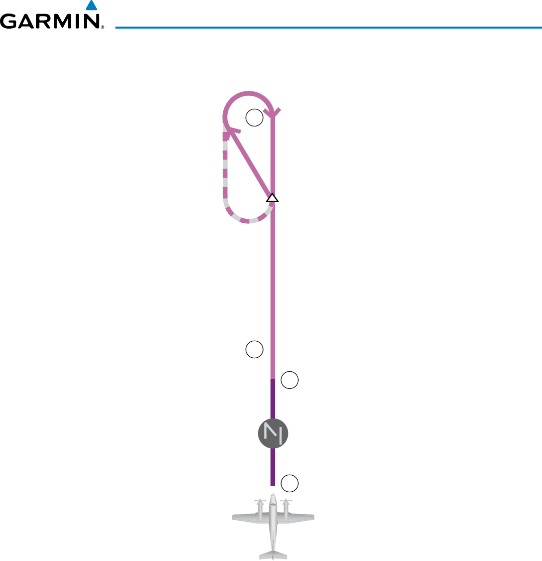
190-00928-04 Rev. A
Garmin G1000 Pilot’s Guide for the Beechcraft 200/B200 Series
543
AUTOMATIC FLIGHT CONTROL SYSTEM
Figure 7-50 Go Around/Missed Approach
3
4
1
2
KCOS
MOGAL
GA Mode
GPS NAV Mode
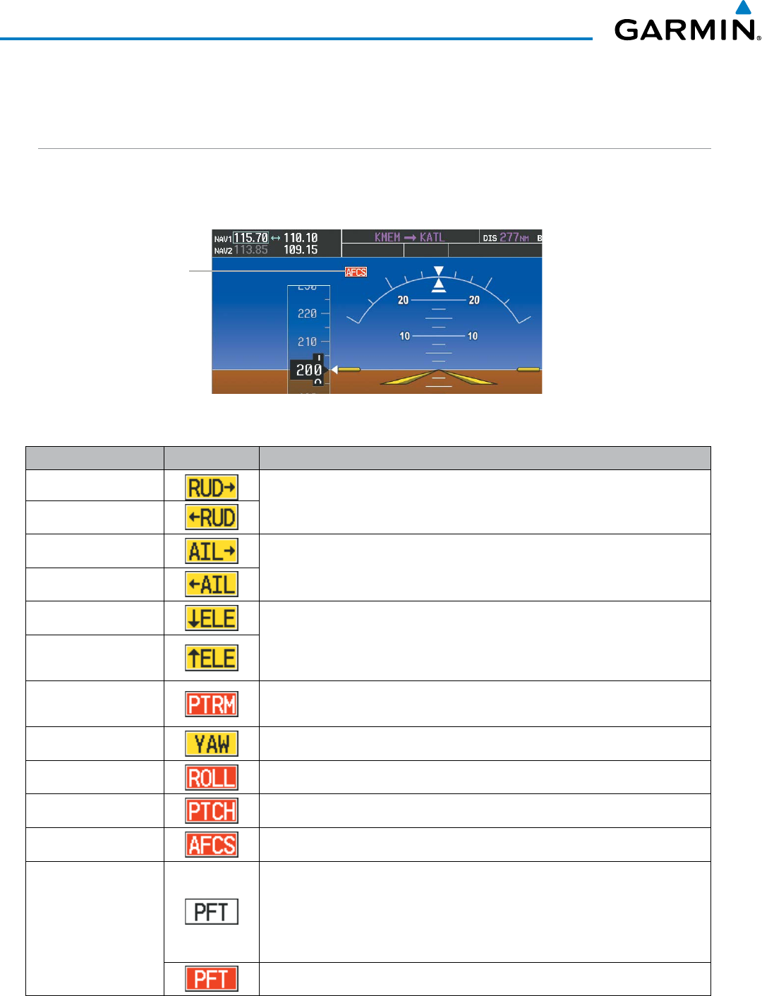
Garmin G1000 Pilot’s Guide for the Beechcraft 200/B200 Series
190-00928-04 Rev. A
544
AUTOMATIC FLIGHT CONTROL SYSTEM
7.7 AFCS ANNUNCIATIONS AND ALERTS
AFCS STATUS ALERTS
The annunciations in Table 7-5 (listed in order of increasing priority) can appear on the PFDs above the
Airspeed and Attitude indicators. Only one annunciation may occur at a time, and messages are prioritized by
criticality.
Figure 7-51 AFCS Status Annunciation
AFCS Status
Annunciation
Alert Condition Annunciation Description
Rudder Mistrim Right
Yaw servo providing sustained force in the indicated direction
Rudder Mistrim Left
Aileron Mistrim Right
Roll servo providing sustained force in the indicated direction
Aileron Mistrim Left
Elevator Mistrim Down
Pitch servo providing sustained force in the indicated direction
Elevator Mistrim Up
Pitch Trim Failure
(or stuck MEPT Switch)
If AP engaged, take control of the aircraft and disengage AP
If AP disengaged, move MEPT switches separately to unstick
Yaw Damper Failure YD control failure
Roll Failure Roll axis control failure; AP and YD inoperative
Pitch Failure Pitch axis control failure; AP and YD inoperative
System Failure AP and MEPT are unavailable; FD may still be available, but YD inoperative
Preflight Test
Performing preflight system test; aural alert sounds at completion
Do not press the AP/YD DISC Switch during servo power-up and preflight system
tests as this may cause the preflight system test to fail or never to start (if servos
fail their power-up tests). Power must be cycled to the servos to remedy the
situation.
Preflight system test failed; aural alert sounds at failure
Table 7-5 AFCS Status Alerts
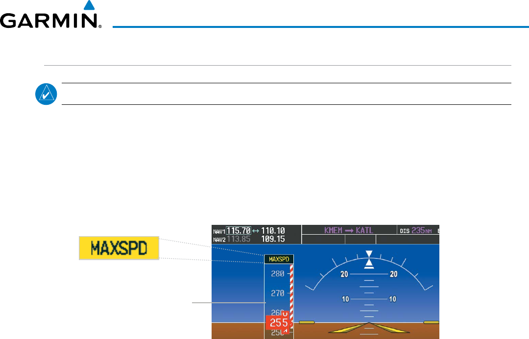
190-00928-04 Rev. A
Garmin G1000 Pilot’s Guide for the Beechcraft 200/B200 Series
545
AUTOMATIC FLIGHT CONTROL SYSTEM
OVERSPEED PROTECTION
NOTE: Overspeed protection is not active in ALT, GS or GP modes.
While Pitch Hold, Vertical Speed, Flight Level Change, Vertical Path Tracking, or an altitude capture mode is
active, airspeed is monitored by the flight director. Overspeed protection is provided to limit the flight director’s
pitch command in situations where the flight director cannot acquire and maintain the mode reference for the
selected vertical mode without exceeding the certified maximum autopilot airspeed.
When Overspeed Protection is active, the Airspeed Reference appears in a box above the Airspeed Indicator,
flashing a yellow ‘MAXSPD’ annunciation. Engine power should be reduced and/or the pitch reference adjusted
to slow the aircraft. The annunciation disappears when the overspeed condition is resolved.
Figure 7-52 Overspeed Annunciation
Airspeed
Indicator
Garmin G1000 Pilot’s Guide for the Beechcraft 200/B200 Series
190-00928-04 Rev. A
546
AUTOMATIC FLIGHT CONTROL SYSTEM
7.8 ABNORMAL OPERATION
SUSPECTED AUTOPILOT MALFUNCTION
NOTE: Consult the aircraft documentation for the location of circuit breakers as well as specifics that may
supplement or amplify this procedure.
If an autopilot failure or trim failure is suspected to have occurred, perform the following steps:
1) Firmly grasp the control wheel.
2) Press and hold the AP/YD DISC Switch. The autopilot will disconnect and power is removed from the trim
motor. Power is also removed from all primary servo motors and engaged solenoids. Note the visual and aural
alerting indicating autopilot disconnect.
3) Retrim the aircraft as needed. Substantial trim adjustment may be needed.
4) Pull the appropriate circuit breaker(s) to electrically isolate the servo and solenoid components.
5) Release the AP/YD DISC Switch.
OVERPOWERING AUTOPILOT SERVOS
In the context of this discussion, “overpowering” refers to any pressure or force applied to the pitch controls
when the autopilot is engaged. A small amount of pressure or force on the pitch controls can cause the autopilot
automatic trim to run to an out-of-trim condition. Therefore, any application of pressure or force to the
controls should be avoided when the autopilot is engaged.
Overpowering the autopilot during flight will cause the autopilot’s automatic trim to run, resulting in an out-
of-trim condition or cause the trim to hit the stop if the action is prolonged. In this case, larger than anticipated
control forces are required after the autopilot is disengaged.
The following steps should be added to the preflight check:
1) Check for proper autopilot operation and ensure the autopilot can be overpowered.
2) Note the forces required to overpower the autopilot servo clutches.

Garmin G1000 Pilot’s Guide for the Beechcraft 200/B200 Series
190-00928-04 Rev. A 547
ADDITIONAL FEATURES
SECTION 8 ADDITIONAL FEATURES
NOTE: With the availability of SafeTaxi
®
, ChartView, or FliteCharts
®
, it may be necessary to carry another
source of charts on-board the aircraft.
Additional features of the system include the following:
• Synthetic Vision Technology (SVT)
• SafeTaxi® diagrams
• ChartView and FliteCharts® electronic charts
• AOPA or AC-U-KWIK Airport Directory
• Satellite telephone and SMS messaging services
• Wi-Fi connections
• SiriusXM Satellite Radio entertainment
• Scheduler
• Flight Data Logging
• Electronic Stability and Protection (ESP™) System
The optional Synthetic Vision Technology (SVT) provides a three-dimensional forward view of terrain features
on the PFD. SVT imagery shows the pilot’s view of relevant features in relation to the aircraft attitude, as well as
the flight path pertaining to the active flight plan.
SafeTaxi diagrams provide detailed taxiway, runway, and ramp information at more than 700 airports in the
United States. By decreasing range on an airport that has a SafeTaxi diagram available, a close up view of the
airport layout can be seen.
The optional ChartView and FliteCharts provide on-board electronic terminal procedures charts. Electronic
charts offer the convenience of rapid access to essential information. Either ChartView or FliteCharts may be
configured in the system, but not both.
The AOPA and AC-U-KWIK Airport Directories offer detailed information for a selected airport, such as available
services, hours of operation, and lodging options.
Iridium Telephone Services and SMS messaging is an optional subscription service offered through Garmin
Connext and Iridium Satellite LLC. Voice and SMS messaging communications are through the Iridium Satellite
Network. Data communications are through Iridium Data Services, or a wireless network (Wi-Fi) when the
aircraft is on the ground.
The optional SiriusXM Satellite Radio entertainment audio feature of the GDL 69A Data Link Receiver handles
more than 170 channels of music, news, and sports. SiriusXM Satellite Radio offers more entertainment choices
and longer range coverage than commercial broadcast stations.
The Scheduler feature can be used to enter and display short term or long term reminder messages such as
Switch fuel tanks, Change oil, or Altimeter-Transponder Check in the Messages Window on the PFD.
The Flight Data Logging feature automatically stores critical flight and engine data on an SD data card.
Approximately 1,000 flight hours can be recorded for each 1GB of available space on the card.
The Electronic Stability and Protection (ESP™) system discourages aircraft operation outside the normal flight
envelope.

Garmin G1000 Pilot’s Guide for the Beechcraft 200/B200 Series
190-00928-04 Rev. A548
ADDITIONAL FEATURES
8.1 SYNTHETIC VISION TECHNOLOGY (SVT)
WARNING:
Use appropriate primary systems for navigation, and for terrain, obstacle, and traffic avoidance.
SVT is intended as an aid to situational awareness only and may not provide either the accuracy or reliability
upon which to solely base decisions and/or plan maneuvers to avoid terrain, obstacles, or traffic.
The optional Synthetic Vision Technology (SVT) is a visual enhancement to the G1000 Integrated Flight Deck.
SVT depicts a forward-looking attitude display of the topography immediately in front of the aircraft. The field of
view is 30 degrees to the left and 35 degrees to the right. SVT information is shown on the Primary Flight Display
(PFD), or on the Multifunction Display (MFD) in Reversionary Mode (Figure 8-128). The depicted imagery is
derived from the aircraft attitude, heading, GPS three-dimensional position, and a nine arc-second database of
terrain, obstacles, and other relevant features. The terrain data resolution of nine arc-seconds, meaning that
the terrain elevation contours are stored in squares measuring nine arc-seconds on each side, is required for the
operation of SVT. Loss of any of the required data, including temporary loss of the GPS signal, will cause SVT to
be disabled until the required data is restored.
The SVT terrain display shows land contours (colors are consistent with those of the topographical map display),
large water features, towers, and other obstacles over 200’ AGL that are included in the obstacle database. Cultural
features on the ground such as roads, highways, railroad tracks, cities, and state boundaries are not displayed even
if those features are found on the MFD map. The terrain display also includes a north–south east–west grid with
lines oriented with true north and spaced at one arc-minute intervals to assist in orientation relative to the terrain.
The Terrain Awareness and Warning System (TAWS) is integrated within SVT to provide visual and auditory
alerts to indicate the presence of terrain and obstacle threats relevant to the projected flight path. Terrain alerts
are displayed in red and yellow shading on the PFD.
The terrain display is intended for situational awareness only. It may not provide the accuracy or fidelity on
which to base decisions and plan maneuvers to avoid terrain or obstacles. Navigation must not be predicated
solely upon the use of the TAWS terrain or obstacle data displayed by the SVT.
The following SVT enhancements appear on the PFD:
• Pathways
• Flight Path Marker
• Horizon Heading Marks
• Traffic Display
• Airport Signs
• Runway Display
• Terrain Alerting
• Obstacle Alerting
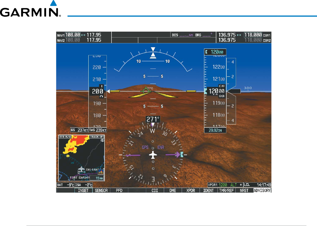
Garmin G1000 Pilot’s Guide for the Beechcraft 200/B200 Series
190-00928-04 Rev. A 549
ADDITIONAL FEATURES
Figure 8-1 Synthetic Vision Imagery
SVT OPERATION
SVT is activated from the PFD using the softkeys located along the bottom edge of the display. Pressing the
softkeys turns the related function on or off. When SVT is enabled, the pitch attitude scale is reduced from 20
degrees up and down to 10 degrees up to 7.5 degrees down.
SVT functions are displayed on three levels of softkeys. The PFD Softkey leads into the PFD function
Softkeys, including synthetic vision. Pressing the
SYN VIS
Softkey displays the SVT feature softkeys. The
softkeys are labeled PATHWAY, SYN
TERR, HRZN
HDG
, and APTSIGNS. The BACK Softkey returns to
the previous level of softkeys. Synthetic Terrain must be active before any other SVT feature may be activated.
HRZN
HDG
, APTSIGNS, and PATHWAY Softkeys are only available when the SYN
TERR Softkey is
activated (gray with black characters). After activating the SYN TERR Softkey, the HRZN
HDG
, APTSIGNS,
and PATHWAY softkeys may be activated in any combination to display desired features. When system power
is cycled, the last selected state (on or off) of the SYN TERR, HRZN
HDG
, APTSIGNS, and PATHWAY
softkeys is remembered by the system.
• PATHWAY Softkey enables display of rectangular boxes that represent course guidance.
• SYN
TERR Softkey enables synthetic terrain depiction.
• HRZN
HDG
Softkey enables horizon heading marks and digits.
• APTSIGNS Softkey enables airport signposts.
Garmin G1000 Pilot’s Guide for the Beechcraft 200/B200 Series
190-00928-04 Rev. A550
ADDITIONAL FEATURES
Figure 8-2 SVT Softkeys
Pressing the BACK Softkey
returns to the top-level softkeys.
BACK
BACK
PFD
Pressing the BACK Softkey returns to the previous level of softkeys.
SYN VIS
PATHWAYSYN TERR HRZN HDG APTSIGNS
Activating and deactivating SVT:
1) Press the PFD Softkey.
2) Press the SYN VIS Softkey.
3) Press the SYN TERR Softkey. The SVT display will cycle on or off with the SYN TERR Softkey.
Activating and deactivating Pathways:
1) Press the PFD Softkey.
2) Press the SYN VIS Softkey.
3) Press the PATHWAY Softkey. The Pathway feature will cycle on or off with the PATHWAY Softkey.
Activating and deactivating Horizon Headings:
1) Press the PFD Softkey.
2) Press the SYN VIS Softkey.
3) Press the HRZN HDG Softkey. The horizon heading display will cycle on or off with the HRZN HDG Softkey.
Activating and deactivating Airport Signs:
1) Press the PFD Softkey.
2) Press the SYN VIS Softkey.
3) Press the APTSIGNS Softkey. Display of airport signs will cycle on or off with the APTSIGNS Softkey.
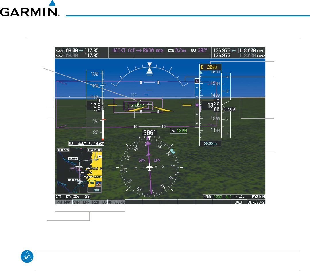
Garmin G1000 Pilot’s Guide for the Beechcraft 200/B200 Series
190-00928-04 Rev. A 551
ADDITIONAL FEATURES
SVT FEATURES
Figure 8-3 SVT on the Primary Flight Display
SVT
Softkeys
Synthetic
Terrain
Pathways
Color
Matches CDI
Indicating
NAV Source
Flight
Path
Marker
Airport
Runway
Zero
Pitch Line
(ZPL) with
Compass
Heading
Marks
Airplane
Symbol
Selected
Altitude
NOTE: Pathways and terrain features are not a substitute for standard course and altitude deviation
information provided by the altimeter, CDI, and VDI.
PATHWAYS
Pathways provide a three-dimensional perspective view of the selected route of flight shown as colored
rectangular boxes representing the horizontal and vertical flight path of the active flight plan. The box
size represents 700 feet wide by 200 feet tall during enroute, oceanic, and terminal flight phases. During
an approach, the box width is 700 feet or one half full scale deviation on the HSI, whichever is less. The
height is 200 feet or one half full scale deviation on the VDI, whichever is less. The altitude at which the
pathway boxes are displayed is determined by the higher of either the selected altitude or the VNAV altitude
programmed for the active leg in the flight plan (Figure 8-4).
The color of the rectangular boxes may be magenta, green, or white depending on the route of flight and
navigation source selected. The active GPS or GPS overlay flight plan leg is represented by magenta boxes
that correspond to the Magenta CDI. A localizer course is represented by green boxes that correspond to a
green CDI. An inactive leg of an active flight plan is represented by white boxes corresponding to a white line
drawn on the Inset map or MFD map indicating an inactive leg.
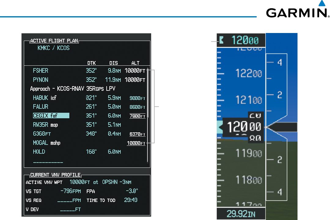
Garmin G1000 Pilot’s Guide for the Beechcraft 200/B200 Series
190-00928-04 Rev. A552
ADDITIONAL FEATURES
Figure 8-4 Programmed and Selected Altitude
Selected
Altitude
Programmed
Altitudes
Pathways provide supplemental glidepath/glideslope information on an active ILS, LPV, LNAV/VNAV, and
some LNAV approaches. Pathways are intended as an aid to situational awareness and should not be used
independent of the CDI, VDI, glide path indicator, and glide slope indicator. They are removed from the
display when the selected navigation information is not available. Pathways are not displayed beyond the
active leg when leg sequencing is suspended and are not displayed on any portion of the flight plan leg that
would lead to intercepting a leg in the wrong direction.
DePaRtuRe anD enRoute
Prior to intercepting an active flight plan leg, pathways are displayed as a series of boxes with pointers at
each corner that point in the direction of the active waypoint. Pathways are not displayed for the first leg
of the flight plan if that segment is a Heading-to-Altitude leg. The first segment displaying pathways is the
first active GPS leg or active leg with a GPS overlay. If this leg of the flight plan route is outside the SVT
field of view, pathways will not be visible until the aircraft has turned toward this leg. While approaching
the center of the active leg and prescribed altitude, the number of pathway boxes decreases to a minimum
of four.
Climb profiles cannot be displayed due to the variables associated with aircraft performance. Flight
plan legs requiring a climb are indicated by pathways displayed at a level above the aircraft at the altitude
selected or programmed.
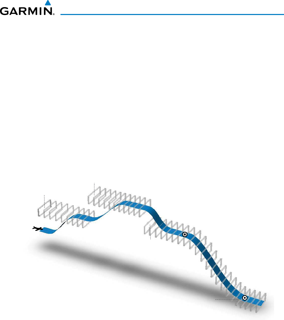
Garmin G1000 Pilot’s Guide for the Beechcraft 200/B200 Series
190-00928-04 Rev. A 553
ADDITIONAL FEATURES
DeScent anD aPPRoacH
Pathways are shown descending only for a programmed descent (Figures 8-5, 8-6). When the flight plan
includes programmed descent segments, pathways are displayed along the descent path provided that the
selected altitude is lower than the programmed altitude.
When an approach providing vertical guidance is activated, Pathways are shown level at the selected
altitude up to the point along the final approach course where the altitude intercepts the extended vertical
descent path, glidepath, or glideslope. From the vertical path descent, glidepath, or glideslope intercept
point, the pathways are shown inbound to the Missed Approach Point (MAP) along the published lateral
and vertical descent path, or at the selected altitude, whichever is lower.
During an ILS approach, the initial approach segment is displayed in magenta at the segment altitudes
if GPS is selected as the navigation source on the CDI. When switching to localizer inbound with LOC
selected as the navigation source on the CDI, pathways are displayed in green along the localizer and glide
slope.
VOR, LOC BC, and ADF approach segments that are approved to be flown using GPS are displayed in
magenta boxes. Segments that are flown using other than GPS or ILS, such as heading legs or VOR final
approach courses are not displayed.
Figure 8-5 SVT Pathways, Enroute and Descent
Climbs NOT
displayed
by pathway
TOD
Programmed descent
displayed by pathway
Selected Altitude
set for Departure
Selected Altitude
set for Enroute
Selected Altitude or Programmed Altitude
(whichever is higher)
Selected Altitude
for Step Down
Non-programmed descents NOT displayed by pathway
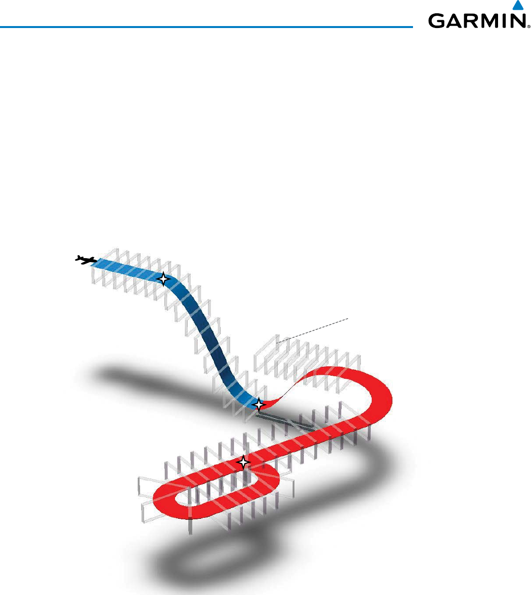
Garmin G1000 Pilot’s Guide for the Beechcraft 200/B200 Series
190-00928-04 Rev. A554
ADDITIONAL FEATURES
MiSSeD aPPRoacH
Upon activating the missed approach, pathways lead to the Missed Approach Holding Point (MAHP) and
are displayed as a level path at the published altitude for the MAHP, or the selected altitude, whichever is
the highest. If the initial missed approach leg is a Course-to-Altitude (CA) leg, the pathways boxes will
be displayed level at the altitude published for the MAHP. If the initial missed approach leg is defined by
a course using other than GPS, pathways are not displayed for that segment. In this case, the pathways
displayed for the next leg may be outside the field of view and will be visible when the aircraft has turned
in the direction of that leg.
Pathways are displayed along each segment including the path required to track course reversals that are
part of a procedure, such as holding patterns. Pathways boxes will not indicate a turn to a MAHP unless a
defined geographical waypoint exists between the MAP and MAHP.
Figure 8-6 SVT Pathways, Approach, Missed Approach, and Holding
Descent displayed
by pathway Selected Altitude
or Programmed Altitude
(whichever is higher)
FAF
MAP
MAHP
Climbs NOT displayed
by pathway
Turn Segment
NOT displayed
by pathway
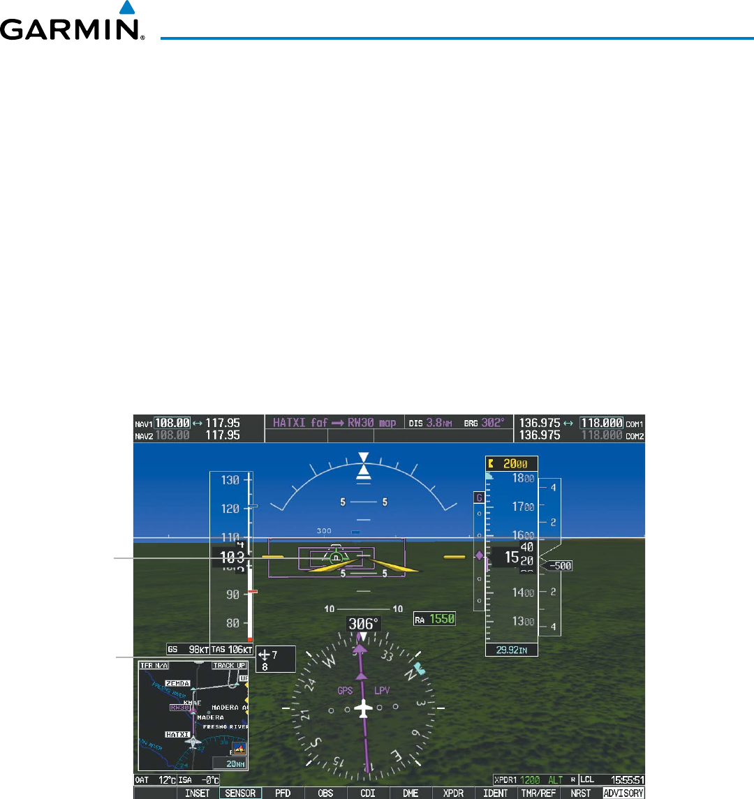
Garmin G1000 Pilot’s Guide for the Beechcraft 200/B200 Series
190-00928-04 Rev. A 555
ADDITIONAL FEATURES
FLIGHT PATH MARKER
The Flight Path Marker (FPM), also known as a Velocity Vector, is displayed on the PFD at groundspeeds
above 30 knots. The FPM depicts the approximate projected path of the aircraft accounting for wind speed
and direction relative to the three-dimensional terrain display.
The FPM is always available when the Synthetic Terrain feature is in operation. The FPM represents the
direction of the flight path as it relates to the terrain and obstacles on the display, while the airplane symbol
represents the aircraft heading.
The FPM works in conjunction with the Pathways feature to assist the pilot in maintaining desired altitudes
and direction when navigating a flight plan. When on course and altitude the FPM is aligned inside the
pathway boxes as shown (Figure 8-7).
The FPM may also be used to identify a possible conflict with the aircraft flight path and distant terrain or
obstacles. Displayed terrain or obstacles in the aircraft’s flight path extending above the FPM could indicate
a potential conflict, even before an alert is issued by TAWS. However, decisions regarding terrain and/or
obstacle avoidance should not be made using only the FPM.
Flight Path
Marker
(FPM)
Wind
Vector
Figure 8-7 Flight Path Marker and Pathways
ZERO PITCH LINE
The Zero Pitch Line is drawn completely across the display and represents the horizon when the terrain
horizon is difficult to distinguish from other terrain being displayed. It may not align with the terrain
horizon, particularly when the terrain is mountainous or when the aircraft is flown at high altitudes.
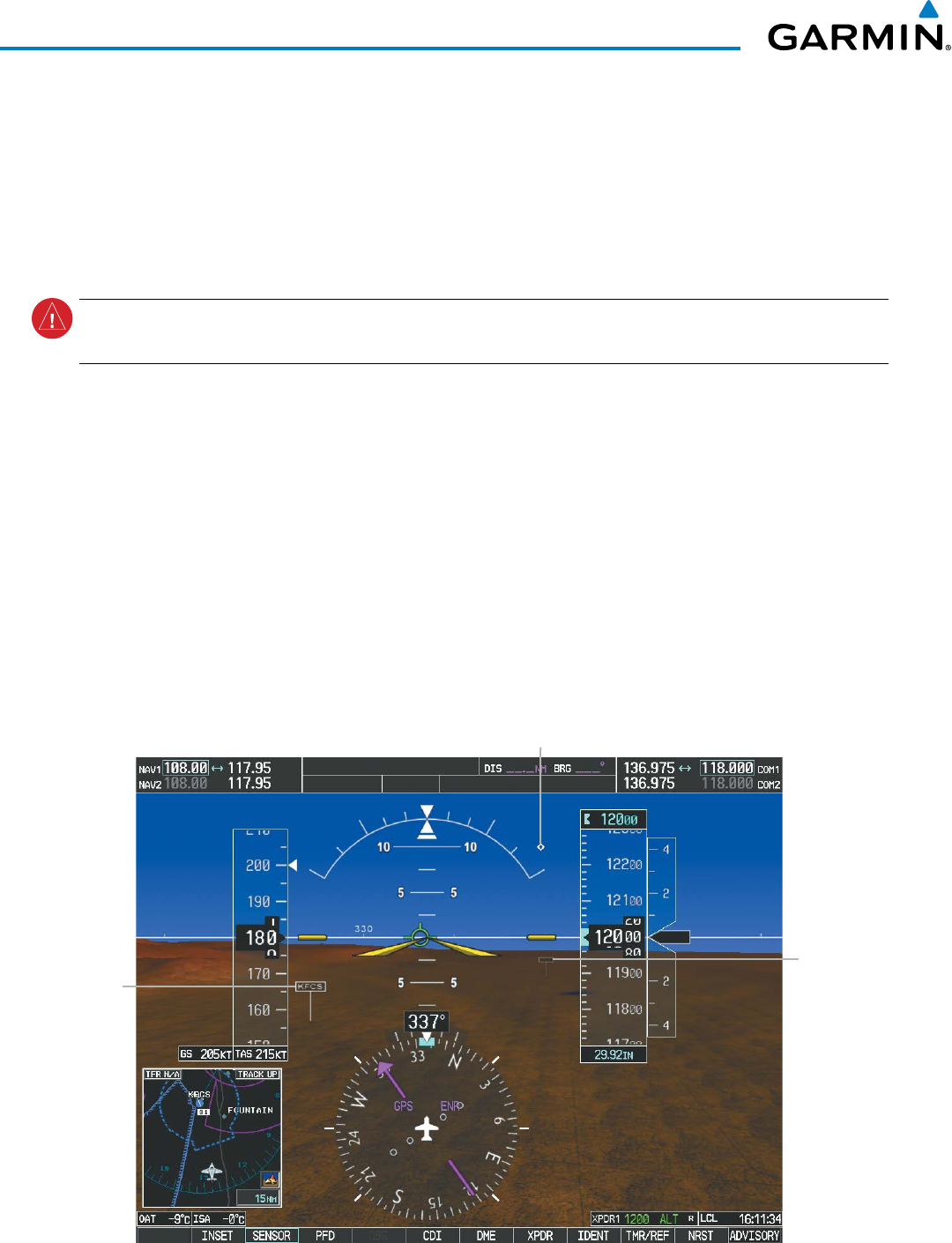
Garmin G1000 Pilot’s Guide for the Beechcraft 200/B200 Series
190-00928-04 Rev. A556
ADDITIONAL FEATURES
HORIZON HEADING
The Horizon Heading is synchronized with the HSI and shows approximately 60 degrees of compass
heading in 30-degree increments on the Zero Pitch Line. Horizon Heading tick marks and digits appearing
on the zero pitch line are not visible behind either the airspeed or altitude display. Horizon Heading is used
for general heading awareness, and is activated and deactivated by pressing the HRZN HDG Softkey.
TRAFFIC
WARNING:
Intruder aircraft at or below 500 ft. AGL may not appear on the SVT display or may appear as a
partial symbol.
Traffic symbols are displayed in their approximate locations as determined by the related traffic systems.
Traffic symbols are displayed in three dimensions, appearing larger as they are getting closer, and smaller
when they are further away. Traffic within 250 feet laterally of the aircraft will not be displayed on the SVT
display. Traffic symbols and coloring are consistent with that used for traffic displayed in the Inset map or
MFD traffic page. If the traffic altitude is unknown, the traffic will not be displayed on the SVT display. For
more details refer to the traffic system discussion in the Hazard Avoidance section.
AIRPORT SIGNS
Airport Signs provide a visual representation of airport location and identification on the synthetic terrain
display. When activated, the signs appear on the display when the aircraft is approximately 15 nm from
an airport and disappear at approximately 4.5 nm. Airport signs are shown without the identifier until
the aircraft is approximately eight nautical miles from the airport. Airport signs are not shown behind the
airspeed or altitude display. Airport signs are activated and deactivated by pressing the APTSIGNS Softkey.
Figure 8-8 Airport Signs
Airport
Sign with
Identifier
(Between
4.5 nm and
8 nm)
Airport
Sign
without
Identifier
(Between
8 nm and
15 nm)
Traffic
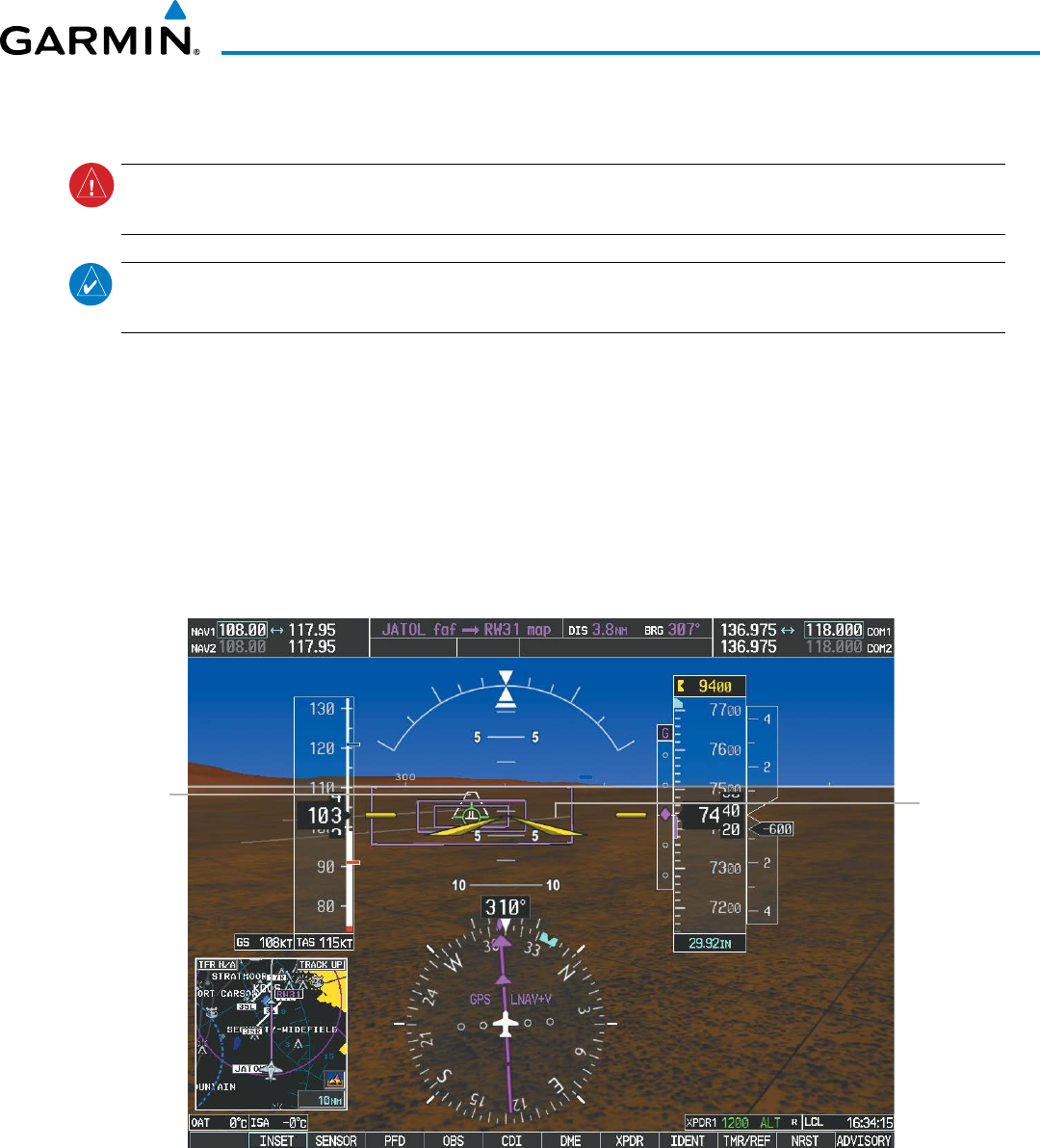
Garmin G1000 Pilot’s Guide for the Beechcraft 200/B200 Series
190-00928-04 Rev. A 557
ADDITIONAL FEATURES
RUNWAYS
WARNING:
Do not use SVT runway depiction as the sole means for determining the proximity of the aircraft
to the runway or for maintaining the proper approach path angle during landing.
NOTE: Not all airports have runways with endpoint data in the database, therefore, these runways are not
displayed.
Runway data provides improved awareness of runway location with respect to the surrounding terrain. All
runway thresholds are depicted at their respective elevations as defined in the database. In some situations,
where threshold elevations differ significantly, crossing runways may appear to be layered. As runways are
displayed, those within 45 degrees of the aircraft heading are displayed in white. Other runways will be gray
in color. When an approach for a specific runway is active, that runway will appear brighter and be outlined
with a white box, regardless of the runway orientation as related to aircraft heading. As the aircraft gets closer
to the runway, more detail such as runway numbers and centerlines will be displayed.
Other
Runway
on Airport
Figure 8-9 Airport Runways
Runway
Selected for
Approach
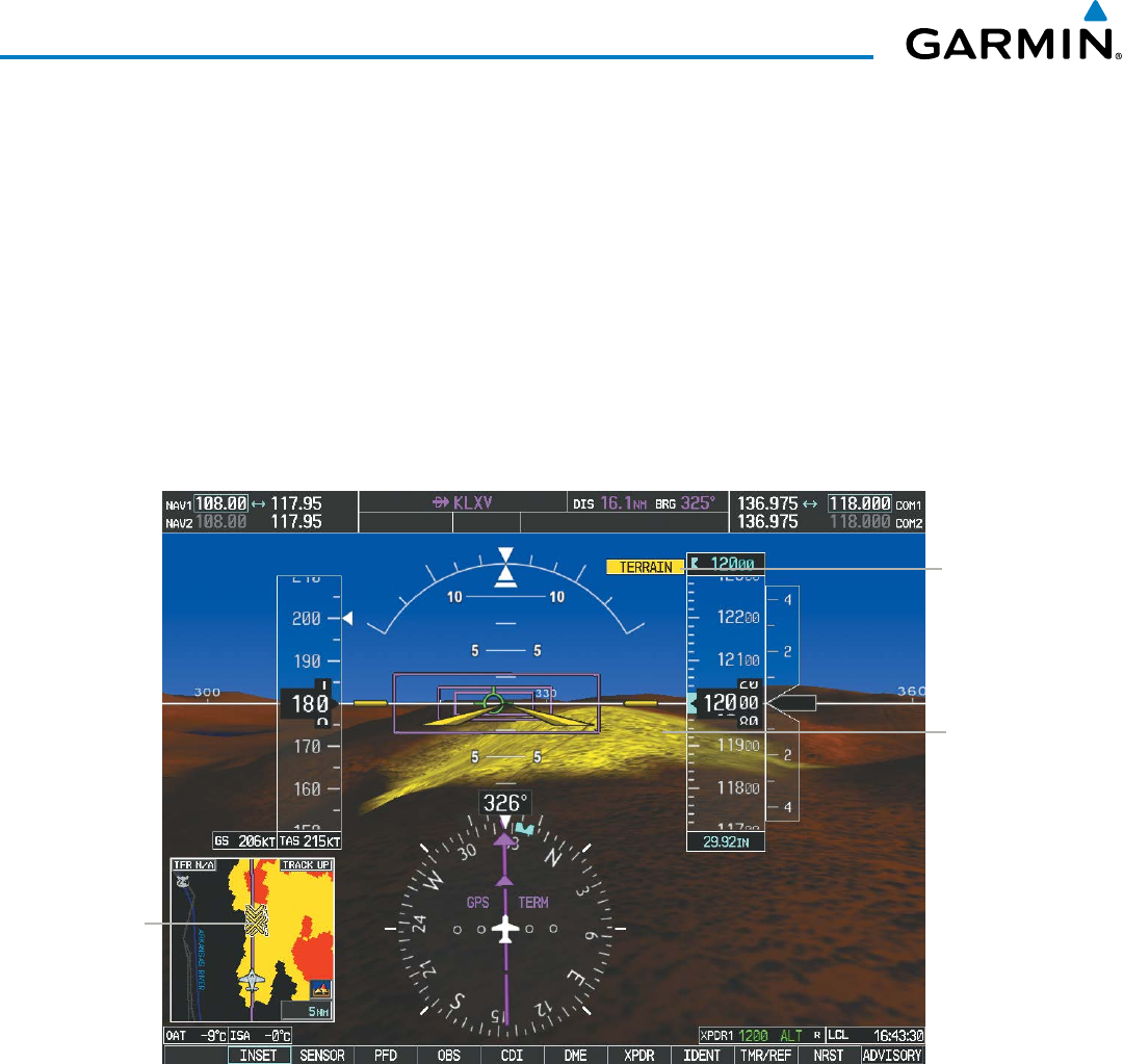
Garmin G1000 Pilot’s Guide for the Beechcraft 200/B200 Series
190-00928-04 Rev. A558
ADDITIONAL FEATURES
TAWS ALERTING
Terrain alerting on the synthetic terrain display is triggered by Forward-looking Terrain Avoidance (FLTA)
alerts. In addition to the yellow terrain shading for a caution alert and the red shading for a warning alert,
TAWS-B alerting will also indicate potential impact points. These potential impact points correspond to red
and/or yellow X symbols on the PFD Inset Map (as shown in Figure 8-10), MFD map displays, and TAWS-B
Page on the MFD. Terrain shading will only occur on the synthetic terrain display on the PFD and TAWS-A
Page on the MFD when using the optional TAWS-A system. No terrain shading nor potential impact points
will be displayed on the PFD inset map or the MFD map display. For more detailed information regarding
TAWS, refer to the Hazard Avoidance Section.
In some instances, a terrain or obstacle alert may be issued with no conflict shading displayed on the
synthetic terrain. In these cases, the conflict is outside the SVT field of view to the left or right of the aircraft.
TERRAIN
Annunciation
Figure 8-10 Terrain Alert
Potential
Impact
Point
Terrain
Caution
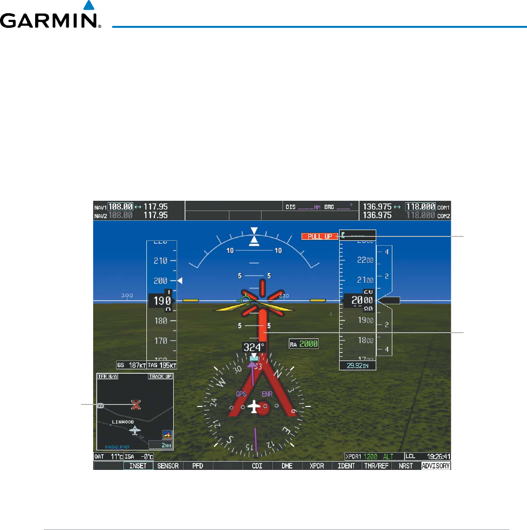
Garmin G1000 Pilot’s Guide for the Beechcraft 200/B200 Series
190-00928-04 Rev. A 559
ADDITIONAL FEATURES
Obstacles are represented on the synthetic terrain display by standard two-dimensional tower symbols found
on the Inset map and MFD maps and charts. Obstacle symbols appear in the perspective view with relative
height above terrain and distance from the aircraft. When employing a TAWS-B system, unlike the Inset
map and MFD moving map display, obstacles on the synthetic terrain display do not change colors to warn
of potential conflict with the aircraft’s flight path until the obstacle is associated with an actual FLTA alert.
Obstacles greater than 1000 feet below the aircraft altitude are not shown. Obstacles are shown behind the
airspeed and altitude displays.
As with terrain alerting on a TAWS-A system, obstacle alerting is limited to the synthetic terrain display on
the PFD and the TAWS-A Page on the MFD.
Figure 8-11 Obstacle
Potential
Impact
Point
Obstacle
Warning
TERRAIN
Annunciation
FIELD OF VIEW
The PFD field of view can be represented on the MFD Navigation Map Page. Two dashed lines forming a
V-shape in front of the aircraft symbol on the map, represent the forward viewing area shown on the PFD.
Configuring field of view:
1) While viewing the Navigation Map Page, press the MENU Key to display the PAGE MENU.
2) Turn the large
FMS
Knob to highlight Map Setup and press the
ENT
Key.
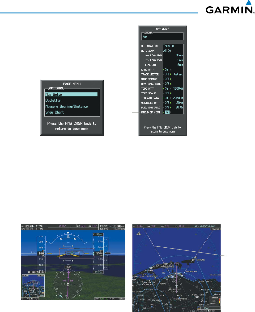
Garmin G1000 Pilot’s Guide for the Beechcraft 200/B200 Series
190-00928-04 Rev. A560
ADDITIONAL FEATURES
Figure 8-12 Option Menus
Navigation Map Page OPTIONS Menu Map Setup Menu, Map Group, Field of View Option
Field of
View
3) Turn the FMS Knob to select the Map Group and press the ENT Key.
4) Turn the large FMS Knob to scroll through the Map Group options to FIELD OF VIEW.
5) Turn the small FMS Knob to select On or Off.
6) Press the
FMS
Knob to return to the Navigation Map Page.
The following figure compares the PFD forward looking depiction with the MFD plan view and FIELD OF
VIEW turned on.
Figure 8-13 PFD and MFD Field of View Comparison
Lines
Depict
PFD Field
of View
SVT View on the PFD
Field of View on the MFD

Garmin G1000 Pilot’s Guide for the Beechcraft 200/B200 Series
190-00928-04 Rev. A 561
ADDITIONAL FEATURES
8.2 SAFETAXI
SafeTaxi is an enhanced feature that gives greater map detail when viewing airports at close range. The
maximum map ranges for enhanced detail are pilot configurable. When viewing at ranges close enough to
show the airport detail, the map reveals taxiways with identifying letters/numbers, airport Hot Spots, and airport
landmarks including ramps, buildings, control towers, and other prominent features. Resolution is greater at
lower map ranges. When the MFD display is within the SafeTaxi ranges, the airplane symbol on the airport
provides enhanced position awareness.
Designated Hot Spots are recognized at airports with many intersecting taxiways and runways, and/or complex
ramp areas. Airport Hot Spots are outlined to caution pilots of areas on an airport surface where positional
awareness confusion or runway incursions happen most often. Hot Spots are defined with a magenta circle or
outline around the region of possible confusion.
Any map page that displays the navigation view can also show the SafeTaxi airport layout within the maximum
configured range. The following is a list of pages where the SafeTaxi feature can be seen:
• Navigation Map Page
• Inset Map (PFD)
• Weather Datalink Page
• Airport Information Page
• Intersection Information Page
• NDB Information Page
• VOR Information Page
• User Waypoint Information Page
• Trip Planning Page
• Nearest Pages
• Active and Stored Flight Plan Pages
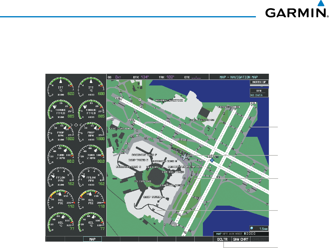
Garmin G1000 Pilot’s Guide for the Beechcraft 200/B200 Series
190-00928-04 Rev. A562
ADDITIONAL FEATURES
During ground operations the aircraft’s position is displayed in reference to taxiways, runways, and airport
features. In the example shown, the aircraft is on taxiway Bravo inside the High Alert Intersection boundary
on KSFO airport. Airport Hot Spots are outlined in magenta. When panning over the airport, features such as
runway holding lines and taxiways are shown at the cursor.
Figure 8-14 SafeTaxi Depiction on the Navigation Map Page
DCLTR
Softkey
Removes
Taxiway
Markings
Airport
Features
Aircraft
Position
Taxiway
Identification
Airport Hot
Spot Outline
The DCLTR Softkey (declutter) label advances to DCLTR-1, DCLTR -2, and DCLTR-3 each time the softkey is
selected for easy recognition of decluttering level. Selecting the DCLTR Softkey removes the taxiway markings
and airport feature labels. Selecting the DCLTR-1 Softkey removes VOR station ID, the VOR symbol, and
intersection names if within the airport plan view. Selecting the DCLTR-2 Softkey removes the airport runway
layout, unless the airport in view is part of an active route structure. Selecting the DCLTR-3 Softkey cycles back
to the original map detail. Refer to Map Declutter Levels in the Flight Management Section.
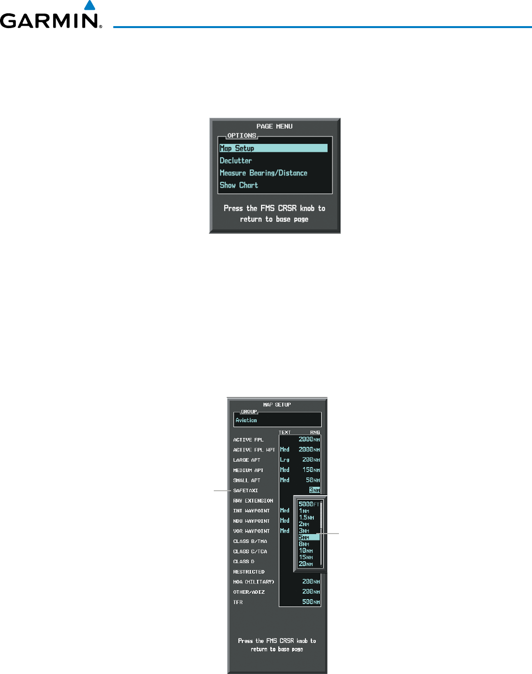
Garmin G1000 Pilot’s Guide for the Beechcraft 200/B200 Series
190-00928-04 Rev. A 563
ADDITIONAL FEATURES
Configuring SafeTaxi range:
1) While viewing the Navigation Map Page, press the MENU Key to display the PAGE MENU.
2) Turn the large
FMS
Knob to highlight the Map Setup Menu Option and press the
ENT
Key.
Figure 8-15 Navigation Map PAGE MENU, Map Setup Option
3) Turn the FMS Knob to select the Aviation Group and press the ENT Key.
4) Turn the large FMS Knob to scroll through the Aviation Group options to SAFETAXI.
5) Turn the small FMS Knob to display the range of distances.
6) Turn either FMS Knob to select the desired distance for maximum SafeTaxi display range.
7) Press the ENT Key to complete the selection.
8) Press the
FMS
Knob to return to the Navigation Map Page.
Figure 8-16 MAP SETUP Menu, Aviation Group, SAFETAXI Range Options
SafeTaxi
Range
Options
SAFETAXI
Option
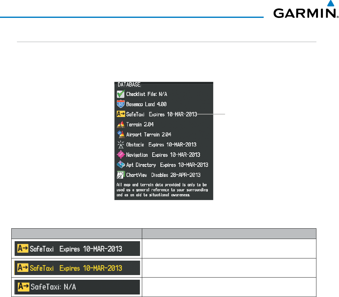
Garmin G1000 Pilot’s Guide for the Beechcraft 200/B200 Series
190-00928-04 Rev. A564
ADDITIONAL FEATURES
SAFETAXI CYCLE NUMBER AND REVISION
SafeTaxi database is revised every 56 days. SafeTaxi is always available for use after the expiration date.
When turning on the system, the Power-up Page indicates whether the databases are current, out of date, or
not available.
Figure 8-17 Power-up Page, SafeTaxi Database
SafeTaxi Database
Power-up Page Display Definition
Normal operation. SafeTaxi database is valid and within current cycle.
SafeTaxi database has expired.
Database card contains no SafeTaxi data.
Table 8-1 SafeTaxi Annunciation Definitions
The SafeTaxi Region, Version, Cycle, Effective date and Expires date of the database cycle can also be found
on the AUX - System Status page, as seen in Figure 8-18.
Select the MFD1 DB Softkey to place the cursor in the DATABASE window. Scroll through the listed
information by turning the FMS Knob or pressing the ENT Key until the SafeTaxi database information is
shown.
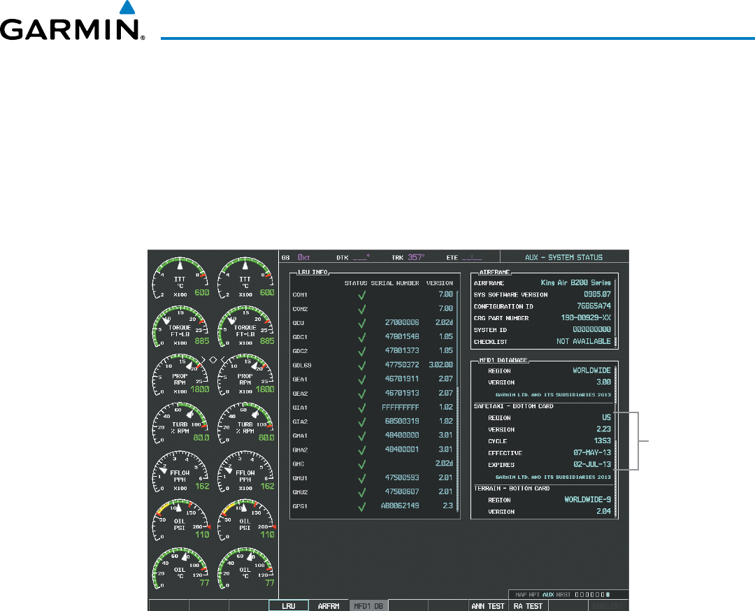
Garmin G1000 Pilot’s Guide for the Beechcraft 200/B200 Series
190-00928-04 Rev. A 565
ADDITIONAL FEATURES
The SafeTaxi database cycle number shown in Figure 8-18, 13S3, is deciphered as follows:
13 – Indicates the year 2013
S – Indicates the data is for SafeTaxi
3 – Indicates the third issue of the SafeTaxi database for the year
The SafeTaxi EFFECTIVE date 07–MAY–13 is the beginning date for the current database cycle. SafeTaxi
EXPIRES date 02–JUL–13 is the revision date for the next database cycle.
Figure 8-18 AUX – System Status Page, SafeTaxi Current Information
SafeTaxi Data
SafeTaxi information appears in blue and yellow text. The EFFECTIVE date appears in blue when data is
current and in yellow when the current date is before the effective date. The EXPIRES date appears in blue
when data is current and in yellow when expired (Figures 8-18 and 8-19). NOT AVAILABLE appears in blue
in the REGION field if SafeTaxi data is not available on the database card (Figure 8-19). An expired SafeTaxi
database is not disabled and will continue to function indefinitely.
Select the MFD1 DB Softkey a second time. The softkey label will change to PFD1 DB. The DATABASE
window will now be displaying database information for PFD1. As before, scroll through the listed information
by turning the FMS Knob or pressing the ENT Key until the SafeTaxi database information is shown.
Select the PFD1 DB Softkey. The softkey label will change to PFD2 DB. The DATABASE window will now
display database information for PFD2. Again, scroll through the listed information by turning the FMS Knob
or pressing the ENT Key until the SafeTaxi database information is shown.
Refer to Updating Garmin Databases in Appendix B for instructions on revising the SafeTaxi database.
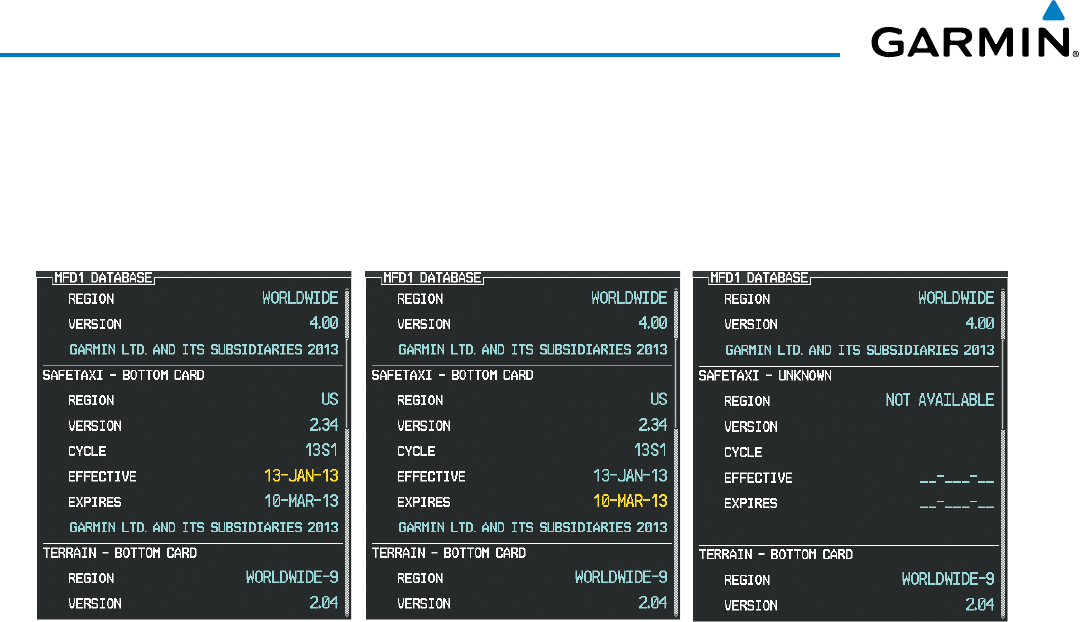
Garmin G1000 Pilot’s Guide for the Beechcraft 200/B200 Series
190-00928-04 Rev. A566
ADDITIONAL FEATURES
Figure 8-19 illustrates possible SafeTaxi database conditions that may appear on the AUX - System Status
Page. The EFFECTIVE date is the beginning date for this database cycle. If the present date is before the
effective date, the EFFECTIVE date appears in yellow and the EXPIRES date appears in blue. The EXPIRES date
is the revision date for the next database cycle. NOT AVAILABLE indicates that SafeTaxi is not available on the
database card or no database card is inserted.
Figure 8-19 AUX – System Status Page, SafeTaxi Database Status
Current Date is before Effective Date SafeTaxi Database has Expired SafeTaxi Database Not Installed
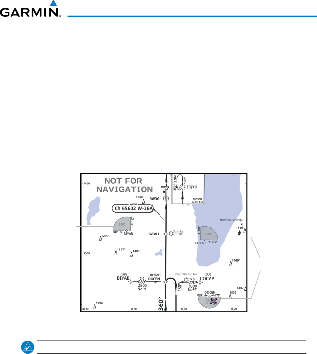
Garmin G1000 Pilot’s Guide for the Beechcraft 200/B200 Series
190-00928-04 Rev. A 567
ADDITIONAL FEATURES
8.3 CHARTVIEW
ChartView resembles the paper version of Jeppesen terminal procedures charts. The charts are displayed in full
color with high-resolution. The MFD depiction shows the aircraft position on the moving map in the planview
of approach charts and on airport diagrams. Airport Hot Spots are outlined in magenta.
The geo-referenced aircraft position is indicated by an aircraft symbol displayed on the chart when the current
position is within the boundaries of the chart. Inset boxes (Figure 8-20) are not considered within the chart
boundaries. Therefore, when the aircraft symbol reaches a chart boundary line, or inset box, the aircraft symbol
is removed from the display.
Figure 8-20 shows examples of off-scale areas, indicated by the grey shading. Note, the grey shading is for
illustrative purposes only and will not appear on the published chart or MFD display. These off-scale areas
appear on the chart to convey supplemental information. However, the depicted geographical position of this
information, as it relates to the chart planview, is not the actual geographic position. Therefore, when the aircraft
symbol appears within one of these areas, the aircraft position indicated is relative to the chart planview, not to
the off-scale area.
Figure 8-20 Sample Chart Indicating Off-Scale Areas
Off-Scale
Area
Off-Scale
Areas
Inset Box
NOTE: Do not maneuver the aircraft based solely upon the geo-referenced aircraft symbol.
The ChartView database subscription is available from Jeppesen, Inc. Available data includes:
• Arrivals (STAR)
• Departure Procedures (DP)
• Approaches
• Airport Diagrams
• NOTAMs
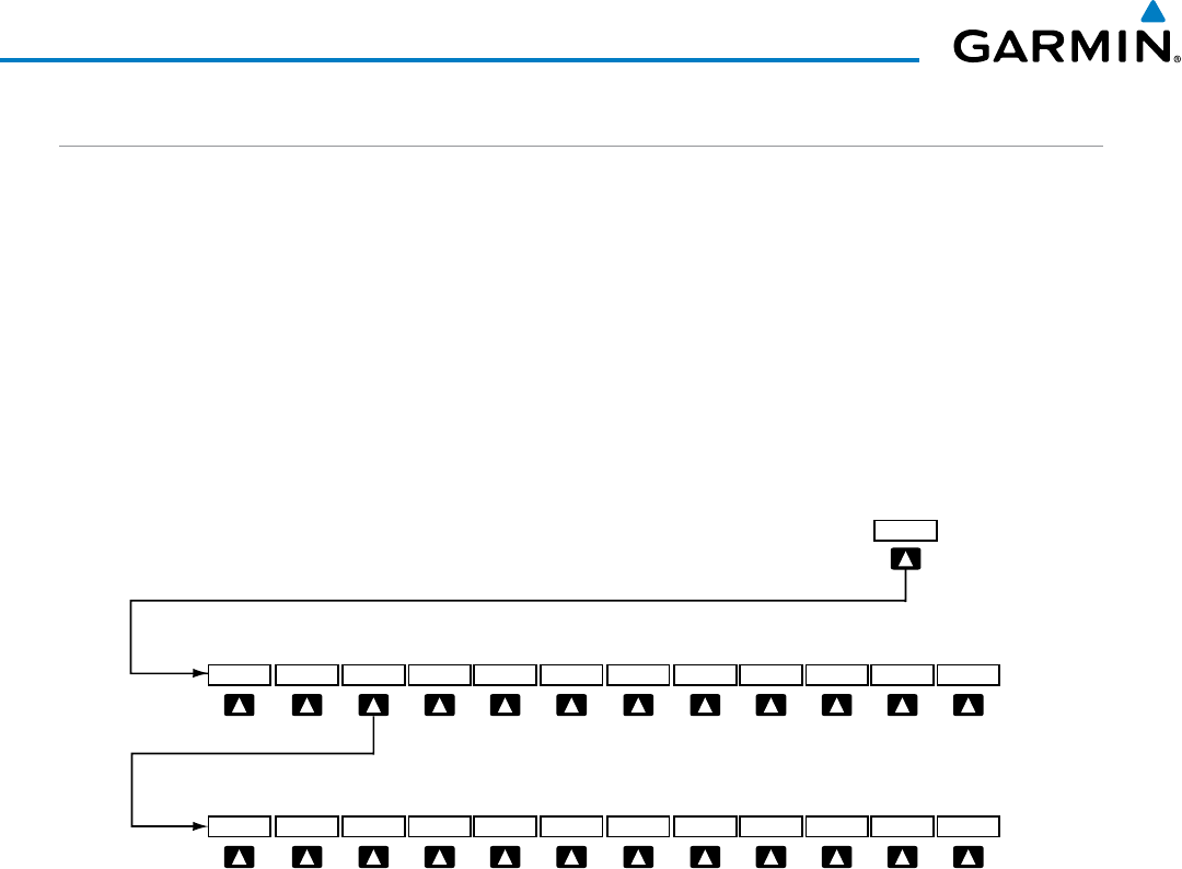
Garmin G1000 Pilot’s Guide for the Beechcraft 200/B200 Series
190-00928-04 Rev. A568
ADDITIONAL FEATURES
CHARTVIEW SOFTKEYS
ChartView functions are displayed on three levels of softkeys. While on the Navigation Map Page, Nearest
Airports Page, or Flight Plan Page, selecting the
SHW CHRT
Softkey displays the available terminal chart and
advances to the chart selection level of softkeys: CHRT OPT, CHRT, INFO, DP, STAR, APR, WX, NOTAM,
and GO
BACK. The chart selection softkeys shown below appear on the Airport Information Page.
Selecting the GO
BACK Softkey reverts to the top level softkeys and previous page.
Selecting the CHRT OPT Softkey advances to the next level of softkeys: ALL, HEADER, PLAN, PROFILE,
MINIMUMS, FIT
WDTH, FULL
SCN, and BACK.
While viewing the CHRT OPT Softkeys, after 45 seconds of softkey inactivity, the system reverts to the chart
selection softkeys.
Figure 8-21 ChartView SHW CHRT, Chart Selection, and Chart Option Softkeys
Selecting the GO BACK Softkey returns
to the top-level softkeys and previous page.
Selecting the BACK Softkey returns
to the Chart Selection Softkeys.
MINIMUMS
CHRT OPT CHRT INFO DP STAR APR WX NOTAM GO BACK
SHW CHRT
ALL HEADER PLAN PROFILE FIT WDTH FULL SCN BACK
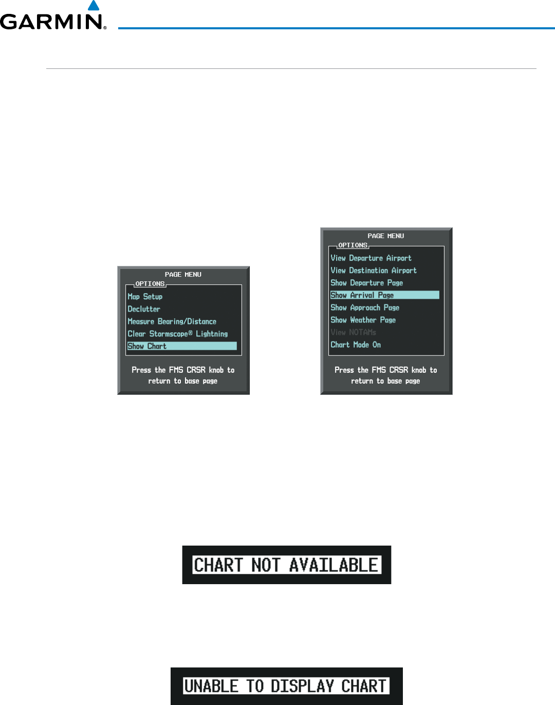
Garmin G1000 Pilot’s Guide for the Beechcraft 200/B200 Series
190-00928-04 Rev. A 569
ADDITIONAL FEATURES
TERMINAL PROCEDURES CHARTS
Selecting Terminal Procedures Charts:
While viewing the Navigation Map Page, Nearest Airport Page, or Flight Plan Page, select the SHW CHRT
Softkey.
Or:
1) Press the MENU Key to display the PAGE MENU.
2) Turn the large FMS Knob to scroll through the OPTIONS Menu to Show Chart.
3) Press the ENT Key to display the chart.
Navigation Map Page OPTIONS Menu Waypoint Airport Information Page OPTIONS Menu
Figure 8-22 Option Menus
On the Waypoint Airport Information Page OPTIONS Menu, select the desired chart and press the ENT Key
to display the chart.
When no terminal procedure chart is available, the banner CHART NOT AVAILABLE appears on the screen.
The CHART NOT AVAILABLE banner does not refer to the FliteCharts subscription, but rather the availability
of a particular airport chart selection or procedure for a selected airport.
Figure 8-23 Chart Not Available Banner
If there is a problem in rendering the data (such as a data error or a failure of an individual chart), the banner
UNABLE TO DISPLAY CHART is then displayed.
Figure 8-24 Unable To Display Chart Banner
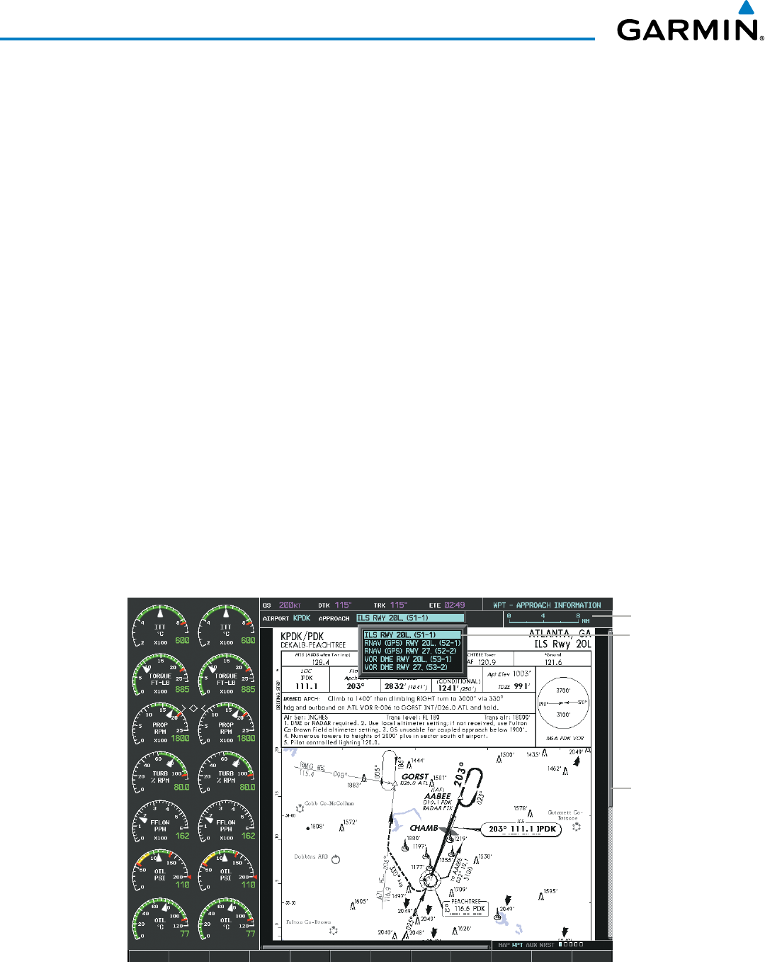
Garmin G1000 Pilot’s Guide for the Beechcraft 200/B200 Series
190-00928-04 Rev. A570
ADDITIONAL FEATURES
When a chart is not available by selecting the SHW CHRT Softkey or selecting a Page Menu Option, charts
may be obtained for other airports from the WPT Pages or Flight Plan Pages.
If a chart is available for the destination airport, or the airport selected in the active flight plan, the chart
appears on the screen. When no flight plan is active, or when not flying to a direct-to destination, selecting the
SHW CHRT Softkey displays the chart for the nearest airport, if available.
The chart shown is one associated with the WPT – Airport Information page. Usually this is the airport runway
diagram. Where no runway diagram exists, but Take Off Minimums or Alternate Minimums are available, that
page appears. If Airport Information pages are unavailable, the Approach Chart for the airport is shown.
Selecting a chart:
1) While viewing the Navigation Map Page, Flight Plan Page, or Nearest Airports Page, select the SHW CHRT
Softkey. The airport diagram or approach chart is displayed on the Airport Information Page.
2) Press the
FMS
Knob to activate the cursor.
3) Turn the large FMS Knob to select either the Airport Identifier Box or the Approach Box. (Select the APR Softkey
if the Approach Box is not currently shown).
4) Turn the small and large FMS Knob to enter the desired airport identifier.
5) Press the ENT Key to complete the airport selection.
6) Turn the large FMS Knob to select the Approach Box.
7) Turn the small
FMS
Knob to show the approach chart selection choices.
8) Turn either
FMS
Knob to scroll through the available charts.
9) Press the ENT Key to complete the chart selection.
Figure 8-25 Approach Information Page, Chart Selection
Select Desired
Approach Chart
from Menu
Scroll Through
Chart With
the
Joystick
Chart Scale
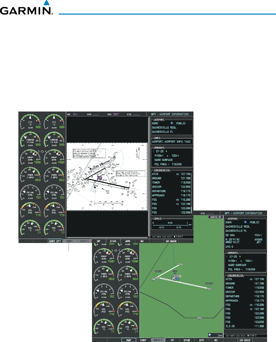
Garmin G1000 Pilot’s Guide for the Beechcraft 200/B200 Series
190-00928-04 Rev. A 571
ADDITIONAL FEATURES
While the APPROACH Box is selected using the FMS Knob, the G1000 softkeys are blank. Once the desired
chart is selected, the chart scale can be changed and the chart page can be scrolled using the Joystick. Pressing
the Joystick centers the chart on the screen.
The aircraft symbol is shown on the chart only if the chart is to scale and the aircraft position is within
the boundaries of the chart. The aircraft symbol is not displayed when the Aircraft Not Shown Icon appears
(Figure 8-29). If the Chart Scale Box displays a banner NOT TO SCALE, the aircraft symbol is not shown. The
Aircraft Not Shown Icon may appear at certain times, even if the chart is displayed to scale.
Selecting the CHRT Softkey switches between the ChartView diagram and the associated map in the WPT
page group. In the example shown, the CHRT Softkey switches between the Gainesville, FL (KGNV) Airport
Diagram and the navigation map on the WPT – Airport Information page.
Figure 8-26 CHRT Softkey, Airport Information Page
Select
CHRT
Softkey
to Switch Between
ChartView and WPT -
Airport Information Page
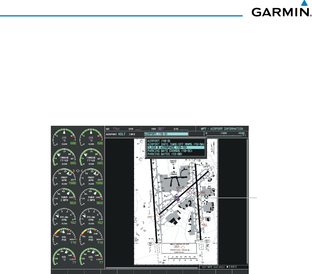
Garmin G1000 Pilot’s Guide for the Beechcraft 200/B200 Series
190-00928-04 Rev. A572
ADDITIONAL FEATURES
Selecting the INFO-1 or INFO-2 Softkey returns to the airport diagram when the view is on a different chart.
If the displayed chart is the airport diagram, the INFO-1 or INFO-2 Softkey has no effect.
The aircraft position is shown in magenta on the ChartView diagrams when the location of the aircraft is
within the chart boundaries. In the example shown, the aircraft is turning onto Taxiway Bravo on the Charlotte,
NC (KCLT) airport.
Another source for additional airport information is from the INFO Box above the chart for certain airports.
This information source is not related to the INFO-1 or INFO-2 Softkey. When the INFO Box is selected using
the FMS Knob, the G1000 softkeys are blank. The Charlotte, NC airport has five additional charts offering
information; the Airport Diagram, Take-off Minimums, Class B Airspace, Airline Parking Gate Coordinates, and
Airline Parking Gate Location. (The numbers in parentheses after the chart name are Jeppesen designators.)
Aircraft
Current
Position
Figure 8-27 Airport Information Page, INFO View, Full Screen Width
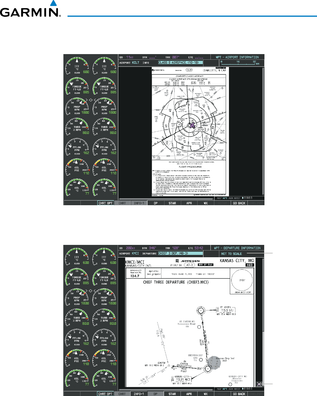
Garmin G1000 Pilot’s Guide for the Beechcraft 200/B200 Series
190-00928-04 Rev. A 573
ADDITIONAL FEATURES
In the example shown in Figure 8-27, the Class B Chart is selected. Pressing the ENT Key displays the
Charlotte Class B Airspace Chart (Figure 8-28).
Figure 8-28 Airport Information Page, Class B Chart Selected from INFO View
Selecting the DP Softkey displays the Departure Procedure Chart if available.
Chart Not
To Scale
Aircraft Not
Shown Icon
Figure 8-29 Departure Information Page
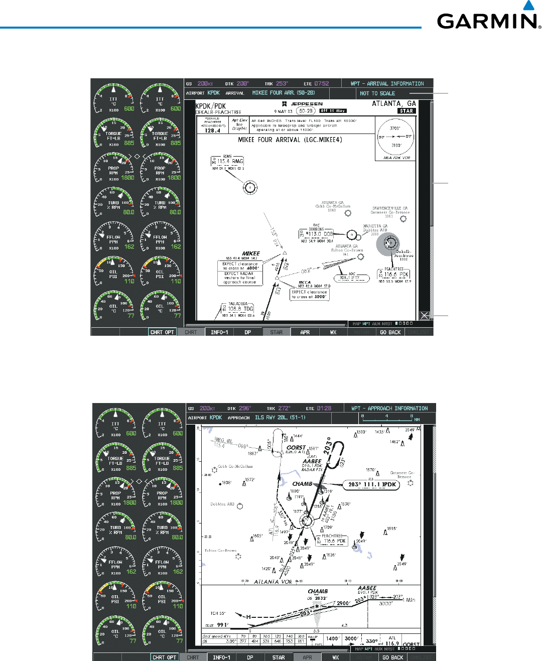
Garmin G1000 Pilot’s Guide for the Beechcraft 200/B200 Series
190-00928-04 Rev. A574
ADDITIONAL FEATURES
Selecting the STAR Softkey displays the Standard Terminal Arrival Chart if available.
Figure 8-30 Arrival Information Page
Aircraft Not
Shown Icon
Change Range
and Scroll
Through the
Chart With the
Joystick
Chart Not
To Scale
Selecting the APR Softkey displays the approach chart for the airport if available.
Figure 8-31 Approach Information Page
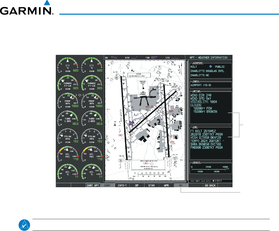
Garmin G1000 Pilot’s Guide for the Beechcraft 200/B200 Series
190-00928-04 Rev. A 575
ADDITIONAL FEATURES
Selecting the WX Softkey shows the airport weather frequency information, and includes weather data such
as METAR and TAF from the SiriusXM Data Link Receiver, when available. Weather information is available
only when a SiriusXM Data Link Receiver is installed and the SiriusXM Weather subscription is current.
Figure 8-32 Weather Information Page
WX Softkey
Selected
WX Info
When
Available
NOTE
: A subdued softkey label indicates the function is disabled.
Recent NOTAMS applicable to the current ChartView cycle are included in the ChartView database. Selecting
the NOTAM Softkey shows the local NOTAM information for selected airports, when available. When NOTAMS
are not available, the NOTAM Softkey label appears subdued and is disabled as shown in Figure 8-32. The
NOTAM Softkey may appear on the Airport Information Page and all of the chart page selections.
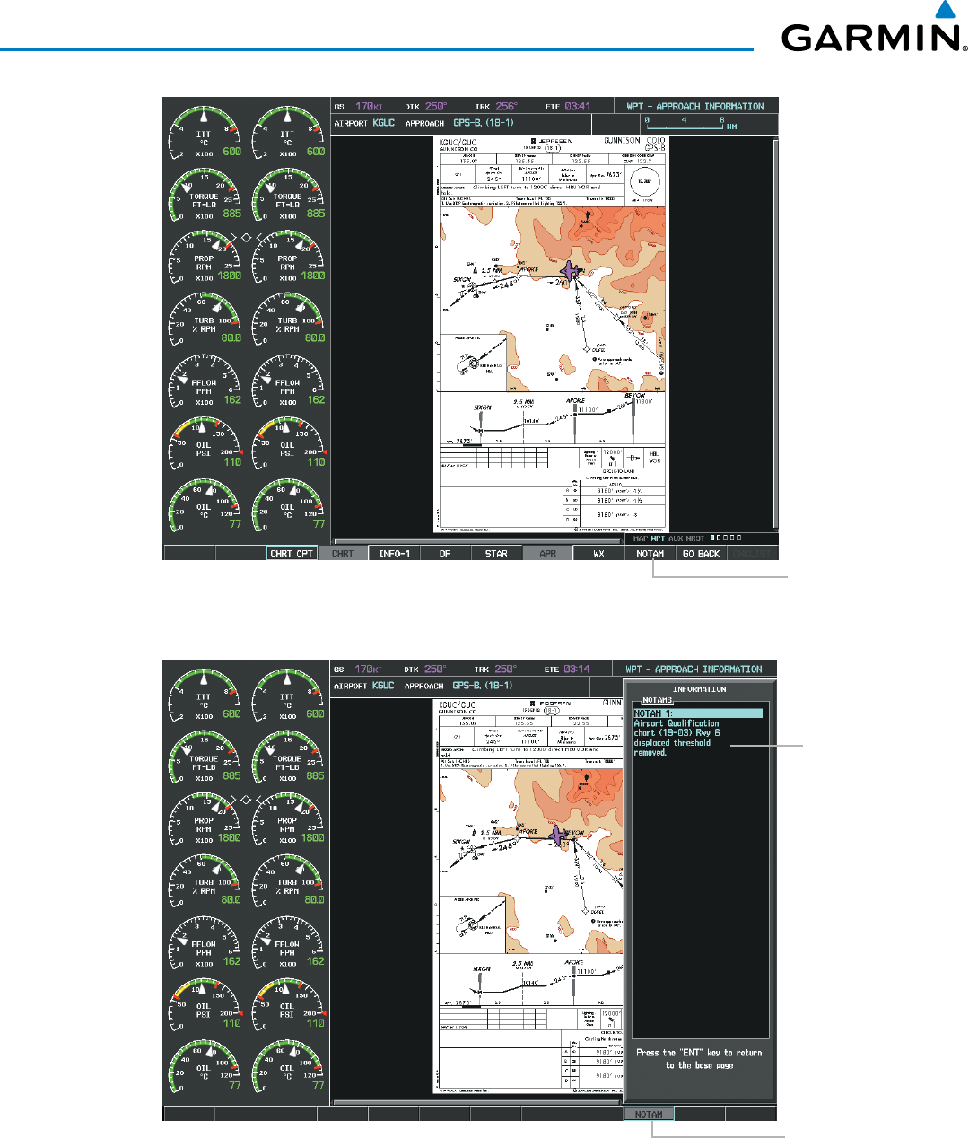
Garmin G1000 Pilot’s Guide for the Beechcraft 200/B200 Series
190-00928-04 Rev. A576
ADDITIONAL FEATURES
Figure 8-33 NOTAM Available
NOTAM
Softkey
Appears for
Selected Airports
Figure 8-34 Airport Information Page, Local NOTAMs
Local
NOTAM on
This Airport
NOTAM
Softkey
Selected
Selecting the NOTAM Softkey again removes the NOTAMS information.
Selecting the GO
BACK Softkey reverts to the previous page (Navigation Map Page, Nearest Pages, or Flight
Plan Page).
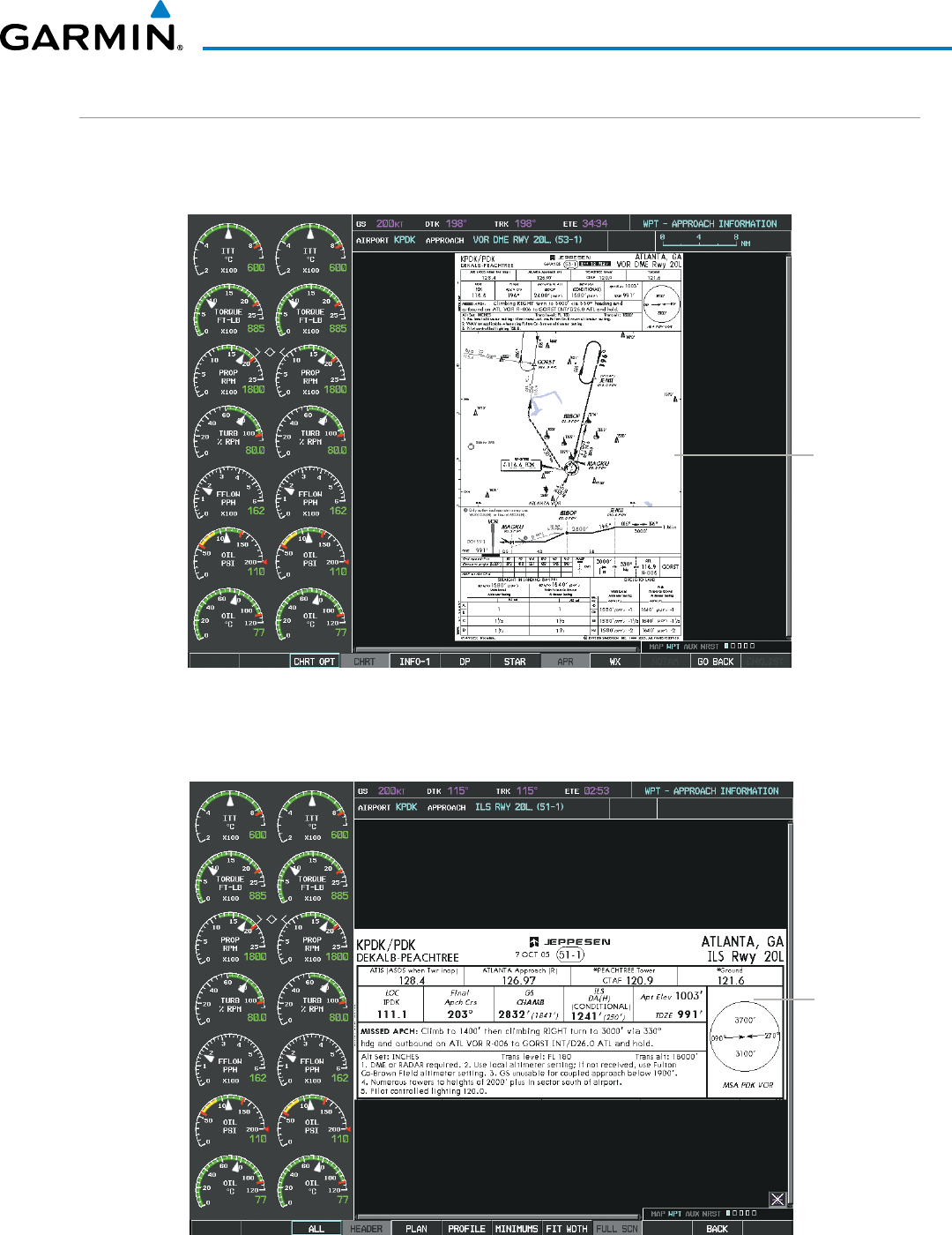
Garmin G1000 Pilot’s Guide for the Beechcraft 200/B200 Series
190-00928-04 Rev. A 577
ADDITIONAL FEATURES
CHART OPTIONS
Selecting the CHRT OPT Softkey displays the next level of softkeys, the chart options level (Figure 8-21).
Selecting the ALL Softkey shows the complete approach chart on the screen.
Complete
Chart
Shown
Figure 8-35 Approach Information Page, ALL View
Selecting the HEADER Softkey shows the header view (approach chart briefing strip) on the screen.
Approach
Chart
Briefing Strip
Figure 8-36 Approach Information Page, Header View
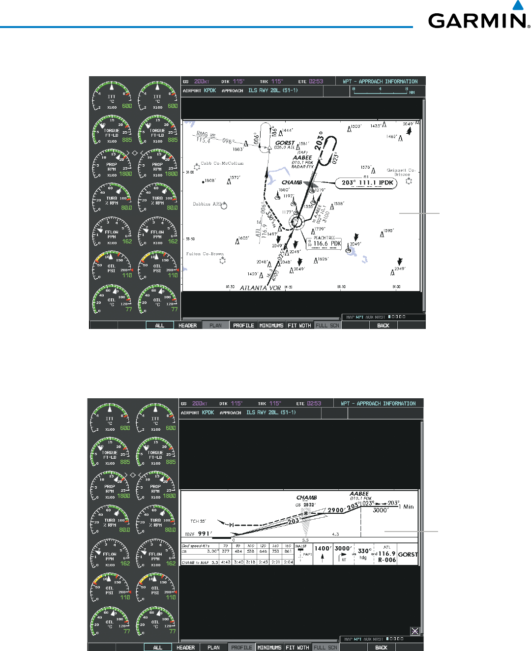
Garmin G1000 Pilot’s Guide for the Beechcraft 200/B200 Series
190-00928-04 Rev. A578
ADDITIONAL FEATURES
Selecting the PLAN Softkey shows the approach chart two dimensional plan view.
Figure 8-37 Approach Information Page, Plan View
Approach
Chart Plan
View
Selecting the PROFILE Softkey displays the approach chart descent profile strip.
Approach
Chart Descent
Profile Strip
Figure 8-38 Approach Information Page, Profile View, Full Screen Width
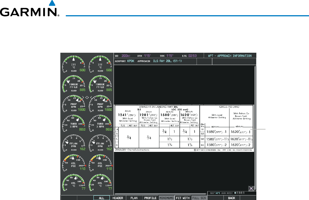
Garmin G1000 Pilot’s Guide for the Beechcraft 200/B200 Series
190-00928-04 Rev. A 579
ADDITIONAL FEATURES
Selecting the MINIMUMS Softkey displays the minimum descent altitude/visibility strip at the bottom of the
approach chart.
Minimum
Descent
Altitude/
Visibility Strip
Figure 8-39 Approach Information Page, Minimums View, Full Screen Width
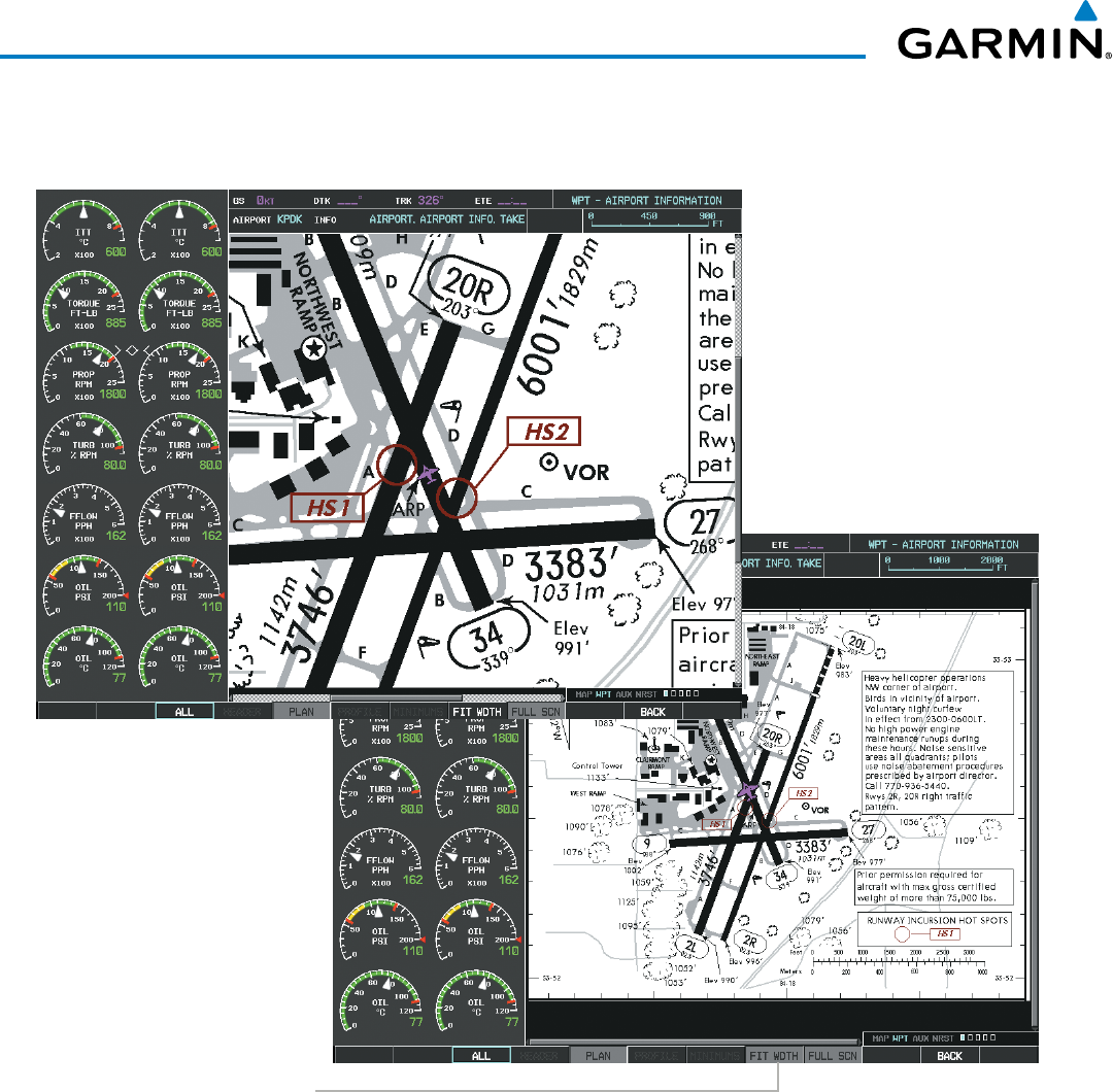
Garmin G1000 Pilot’s Guide for the Beechcraft 200/B200 Series
190-00928-04 Rev. A580
ADDITIONAL FEATURES
If the chart scale has been adjusted to view a small area of the chart, selecting the FIT WIDTH Softkey
changes the chart size to fit the available screen width.
Select
FIT WDTH
Softkey to Show
Full Chart Width
Figure 8-40 Airport Information Page, FIT WDTH Softkey Selected
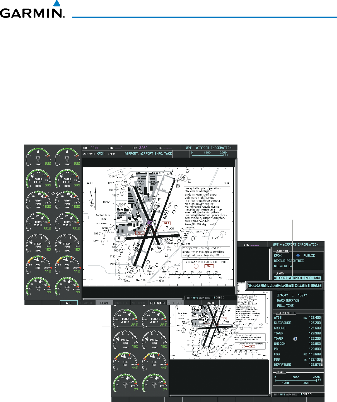
Garmin G1000 Pilot’s Guide for the Beechcraft 200/B200 Series
190-00928-04 Rev. A 581
ADDITIONAL FEATURES
Selecting the FULL
SCN Softkey alternates between removing and replacing the data window to the right.
Selecting Additional Information:
1) While viewing the Airport Taxi Diagram, select the FULL SCN Softkey to display the information windows
(AIRPORT, INFO).
2) Press the
FMS
Knob to activate the cursor.
3) Turn the large
FMS
Knob to highlight the AIRPORT, INFO, RUNWAYS, or FREQUENCIES Box (INFO Box shown).
4) Turn the small FMS Knob to select the INFO Box choices. If multiple choices are available, scroll to the desired
choice with the large FMS Knob and press the ENT Key to complete the selection.
5) Press the
FMS
Knob again to deactivate the cursor.
Figure 8-41 Airport Information Page, Full Screen and Info Window
Select
FULL SCN
Softkey to Switch
Between Chart on Full
Screen and Chart with
Info Window
Available
Information
Selecting the BACK Softkey, or waiting for 45 seconds reverts to the chart selection softkeys.
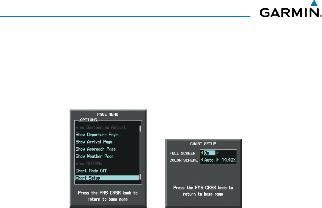
Garmin G1000 Pilot’s Guide for the Beechcraft 200/B200 Series
190-00928-04 Rev. A582
ADDITIONAL FEATURES
The full screen view can also be selected by using the page menu option.
Selecting full screen On or Off:
1) While viewing a terminal chart press the MENU Key to display the Page Menu OPTIONS.
2) Turn the large
FMS
Knob to highlight the Chart Setup Menu Option and press the
ENT
Key.
3) Turn the large
FMS
Knob to move between the FULL SCREEN and COLOR SCHEME Options.
4) Turn the small
FMS
Knob to choose between the On and Off Full Screen Options.
Figure 8-42 Page Menus
Full Screen On/Off SelectionChart Setup Option
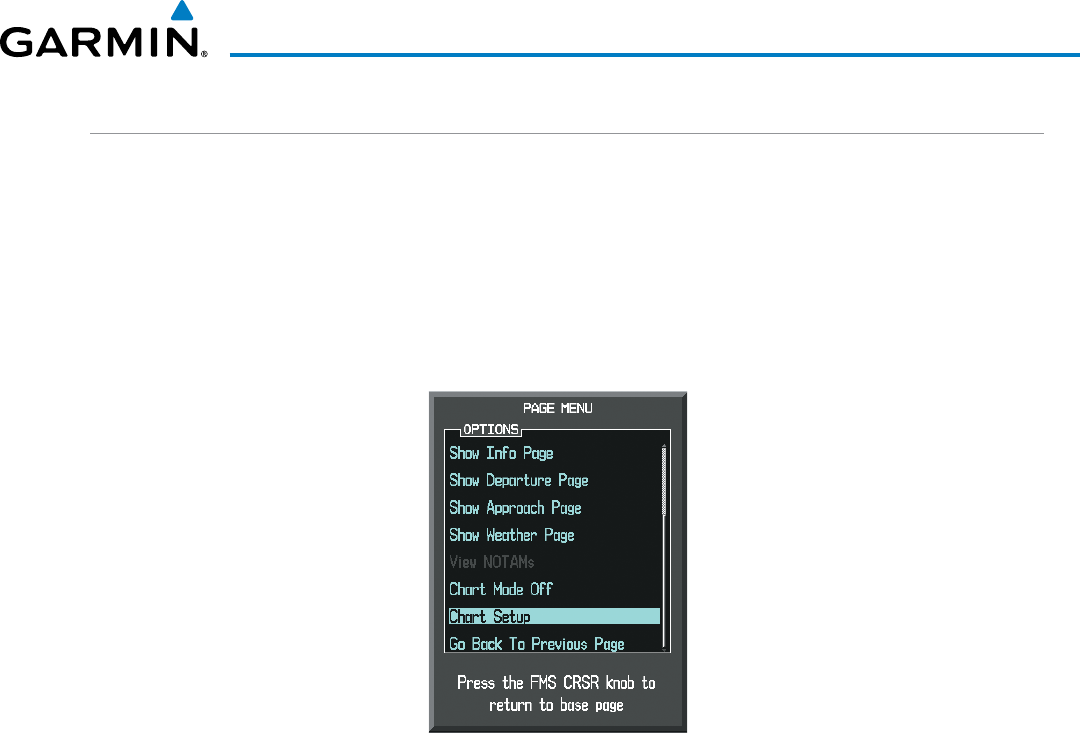
Garmin G1000 Pilot’s Guide for the Beechcraft 200/B200 Series
190-00928-04 Rev. A 583
ADDITIONAL FEATURES
DAY/NIGHT VIEW
ChartView can be displayed on a white or black background for day or night viewing. The Day View offers
a better presentation in a bright environment. The Night View gives a better presentation for viewing in a dark
environment. When the CHART SETUP Box is selected the MFD softkeys are blank.
Selecting Day, Night, or Automatic View:
1) While viewing a terminal chart press the MENU Key to display the Page Menu OPTIONS.
2) Turn the large
FMS
Knob to highlight the Chart Setup Menu Option and press the
ENT
Key.
Figure 8-43 Waypoint Information Page, OPTIONS Menu
3) Turn the large
FMS
Knob to move to the COLOR SCHEME Option (Figure 8‑44).
4) Turn the small
FMS
Knob to choose between Day, Auto, and Night Options.
5) If Auto Mode is selected, turn the large FMS Knob to select the percentage field. Use the small FMS Knob to
change the percentage value. The percentage value is the day/night crossover point based on the percentage of
backlighting intensity. For example, if the value is set to 15%, the day/night display changes when the display
backlight reaches 15% of full brightness.
The display must be changed in order for the new setting to become active. This may be accomplished by
selecting another page or changing the display range.
6) Press the FMS Knob when finished to remove the Chart Setup Menu.
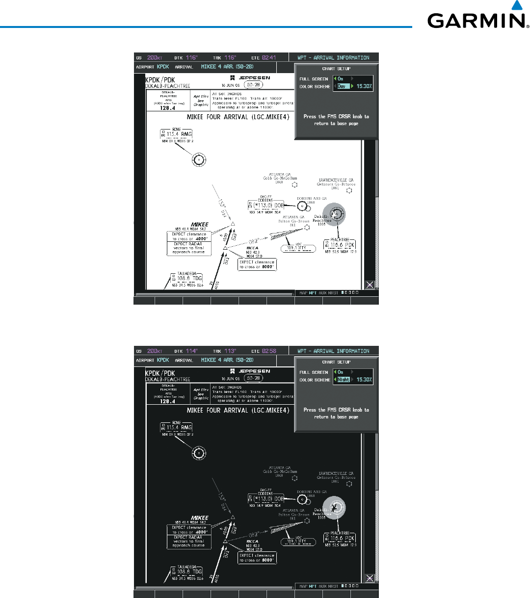
Garmin G1000 Pilot’s Guide for the Beechcraft 200/B200 Series
190-00928-04 Rev. A584
ADDITIONAL FEATURES
Figure 8-44 Arrival Information Page, Day View
Figure 8-45 Arrival Information Page, Night View
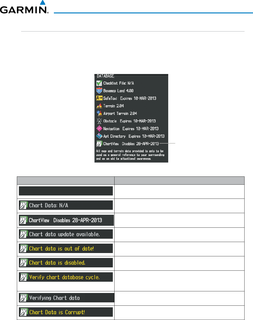
Garmin G1000 Pilot’s Guide for the Beechcraft 200/B200 Series
190-00928-04 Rev. A 585
ADDITIONAL FEATURES
CHARTVIEW CYCLE NUMBER AND EXPIRATION DATE
ChartView database is revised every 14 days. Charts are still viewable during a period that extends from the
cycle expiration date to the disables date. ChartView is disabled 70 days after the expiration date and is no
longer available for viewing. When turning on the system, the Power-up Page displays the current status of the
ChartView database. See the table below for the various ChartView Power-up Page displays and the definition
of each.
Figure 8-46 Power-up Page, ChartView Database
ChartView Database
Power-up Page Display Definition
Blank Line. system is not configured for ChartView. Contact a Garmin‑
authorized service center for configuration.
System is configured for ChartView but no chart database is installed.
Contact Jeppesen for a ChartView database.
Normal operation. ChartView database is valid and within current
cycle.
ChartView database is within 1 week after expiration date. A new cycle
is available for update.
ChartView database is beyond 1 week after expiration date, but still
within the 70 day viewing period.
ChartView database has timed out. Database is beyond 70 days after
expiration date. ChartView database is no longer available for viewing.
System time is not available. GPS satellite data is unknown or the
system has not yet locked onto satellites. Check database cycle number
for effectivity.
System is verifying chart database when new cycle is installed for the
first time.
After verifying, chart database is found to be corrupt. ChartView is not
available.
Table 8-2 ChartView Power-up Page Annunciations and Definitions
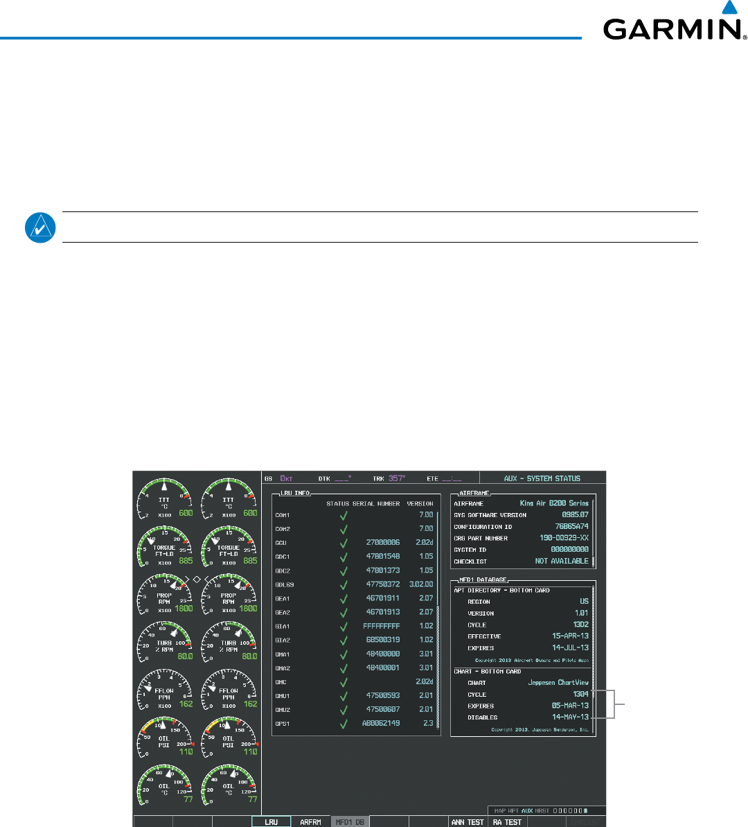
Garmin G1000 Pilot’s Guide for the Beechcraft 200/B200 Series
190-00928-04 Rev. A586
ADDITIONAL FEATURES
The ChartView time critical information can also be found on the AUX - System Status page. The database
CYCLE number, EXPIRES, and DISABLES dates of the ChartView subscription appear in either blue or yellow
text. When the ChartView EXPIRES date is reached, ChartView becomes inoperative 70 days later. This is
shown as the DISABLES date. When the DISABLES date is reached, charts are no longer available for viewing.
The SHW CHRT Softkey label then appears subdued and is disabled until a revised issue of ChartView is
installed.
NOTE
: A subdued softkey label indicates the function is disabled.
Select the MFD1 DB Softkey to place the cursor in the DATABASE window. Scroll through the listed
information by turning the FMS Knob or pressing the ENT Key until the ChartView database information is
shown.
The ChartView database cycle number shown in the figure, 1304, is deciphered as follows:
13 – Indicates the year 2013
04 – Indicates the fourth issue of the ChartView database for the year
The EXPIRES date 05–MAR–13 is the date that this database should be replaced with the next issue.
The DISABLES date 14–MAY–13 is the date that this database becomes inoperative.
Figure 8-47 AUX – System Status Page, ChartView Current and Available
ChartView
Data
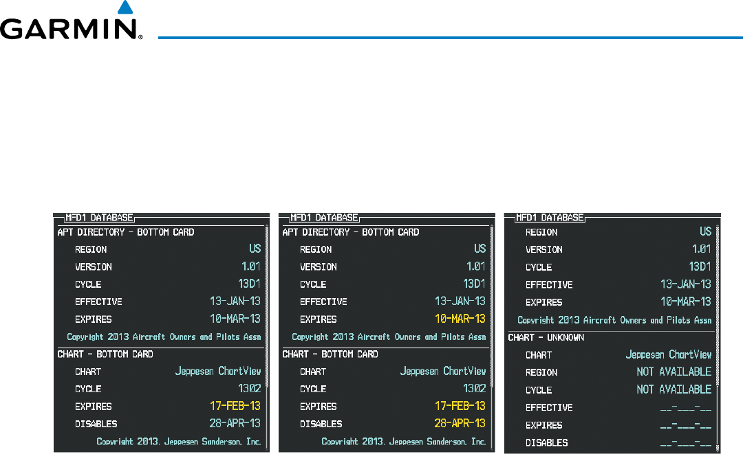
Garmin G1000 Pilot’s Guide for the Beechcraft 200/B200 Series
190-00928-04 Rev. A 587
ADDITIONAL FEATURES
The ChartView database is obtained directly from Jeppesen. Refer to Updating Jeppesen Databases in
Appendix B for instructions on revising the ChartView database.
Other possible AUX - System Status page conditions are shown in Figure 8-48. The EXPIRES date, in yellow,
is the revision date for the next database cycle. The DISABLES date, in yellow, is the date that this database
cycle is no longer viewable. CYCLE NOT AVAILABLE in blue, indicates no ChartView data is available on the
database card or no database card is inserted.
Figure 8-48 AUX – System Status Page, ChartView Database Status
ChartView Database is Disabled
ChartView has Expired, but is not Disabled ChartView Database is Not Available
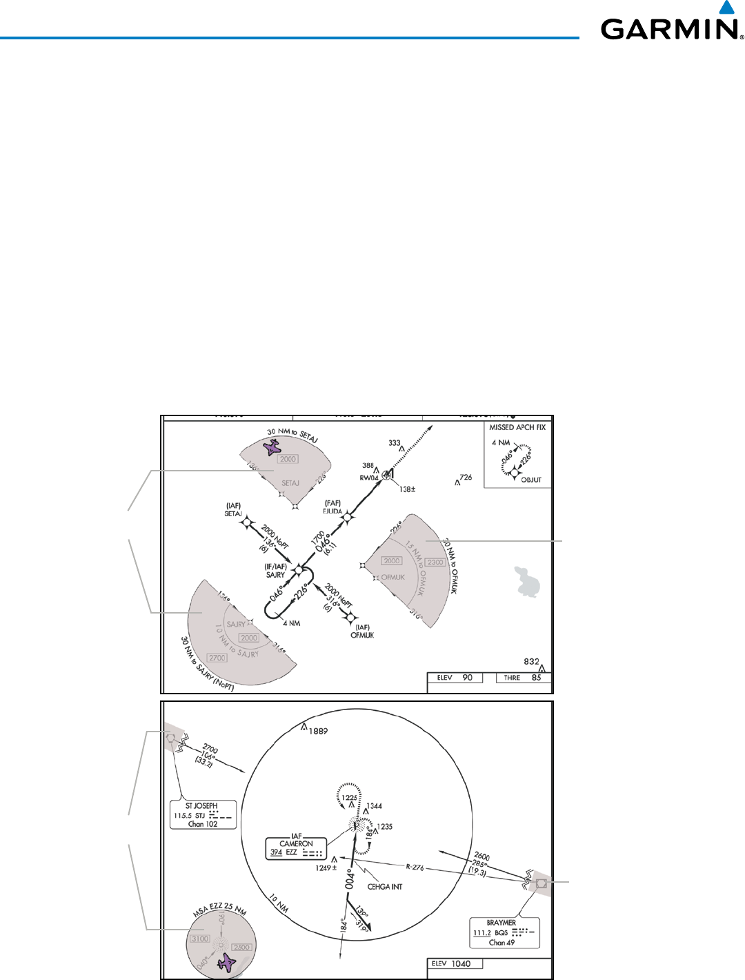
Garmin G1000 Pilot’s Guide for the Beechcraft 200/B200 Series
190-00928-04 Rev. A588
ADDITIONAL FEATURES
8.4 FLITECHARTS
FliteCharts resemble the paper version of AeroNav Services terminal procedures charts. The charts are displayed
with high-resolution and in color for applicable charts.
The geo-referenced aircraft position is indicated by an aircraft symbol displayed on the chart when the current
position is within the boundaries of the chart. Not all charts are geo-referenced. These charts will display an
Aircraft Not Shown Icon in the lower right corner of the MFD, as in Figure 8-54.
An aircraft symbol may be displayed within an off-scale area depicted on some charts. Figure 8-49 shows
examples of off-scale areas, indicated by the grey shading. Note, these areas are not shaded on the published
chart. These off-scale areas appear on the chart to convey supplemental information. However, the depicted
geographical position of this information, as it relates to the chart planview, is not the actual geographic position.
Therefore, when the aircraft symbol appears within one of these areas, the aircraft position indicated is relative to
the chart planview, not to the off-scale area.
The FliteCharts database subscription is available from Garmin. Available data includes:
• Arrivals (STAR)
• Departure Procedures (DP)
• Approaches
• Airport Diagrams
Figure 8-49 Sample Chart Indicating Off-Scale Areas
Off-Scale
Area
Off-Scale
Areas
Off-Scale
Area
Off-Scale
Areas
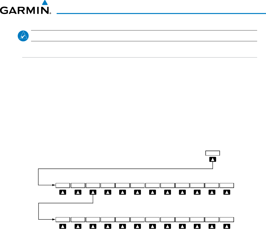
Garmin G1000 Pilot’s Guide for the Beechcraft 200/B200 Series
190-00928-04 Rev. A 589
ADDITIONAL FEATURES
NOTE: Do not maneuver the aircraft based solely upon the geo-referenced aircraft symbol.
FLITECHARTS SOFTKEYS
FliteCharts functions are displayed on three levels of softkeys. While on the Navigation Map Page, Nearest
Airports Page, or Flight Plan Page, selecting the
SHW CHRT
Softkey displays the available terminal chart and
advances to the chart selection level of softkeys: CHRT OPT, CHRT, INFO, DP, STAR, APR, WX, and
GO
BACK. The chart selection softkeys appear on the Airport Information Page.
Selecting the GO
BACK Softkey reverts to the top level softkeys and previous page.
Selecting the CHRT OPT Softkey displays the available terminal chart and advances to the next level of
softkeys: ALL, FIT
WDTH, FULL
SCN, and BACK.
While viewing the CHRT OPT Softkeys, after 45 seconds of softkey inactivity, the system reverts to the chart
selection softkeys.
NOTAMs are not available with FliteCharts. The NOTAM Softkey label appears subdued and is disabled.
Figure 8-50 FliteCharts SHW CHRT, Chart Selection, and Chart Option Softkeys
Selecting the GO BACK Softkey returns
to the top-level softkeys and previous page.
Selecting the BACK Softkey returns
to the Chart Selection Softkeys.
ALL
GO BACK
SHW CHRT
WX
APR
STAR
DP
INFO
CHRT
CHRT OPT
FIT WDTH
FULL SCN
BACK
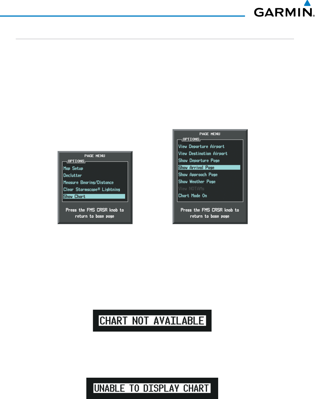
Garmin G1000 Pilot’s Guide for the Beechcraft 200/B200 Series
190-00928-04 Rev. A590
ADDITIONAL FEATURES
TERMINAL PROCEDURES CHARTS
Selecting Terminal Procedures Charts:
While viewing the Navigation Map Page, Nearest Airport Page, or Flight Plan Page, select the SHW CHRT
Softkey.
Or:
1) Press the MENU Key to display the PAGE MENU.
2) Turn the large FMS Knob to scroll through the OPTIONS Menu to Show Chart.
3) Press the ENT Key to display the chart.
Navigation Map Page OPTIONS Menu Waypoint Airport Information Page OPTIONS Menu
Figure 8-51 Option Menus
On the Waypoint Airport Information Page OPTIONS Menu, select the desired chart and press the ENT Key
to display the chart.
When no terminal procedure chart is available, the banner CHART NOT AVAILABLE appears on the screen.
The CHART NOT AVAILABLE banner does not refer to the FliteCharts subscription, but rather the availability
of a particular airport chart selection or procedure for a selected airport.
Figure 8-52 Chart Not Available Banner
If there is a problem in rendering the data (such as a data error or a failure of an individual chart), the banner
UNABLE TO DISPLAY CHART is then displayed.
Figure 8-53 Unable To Display Chart Banner
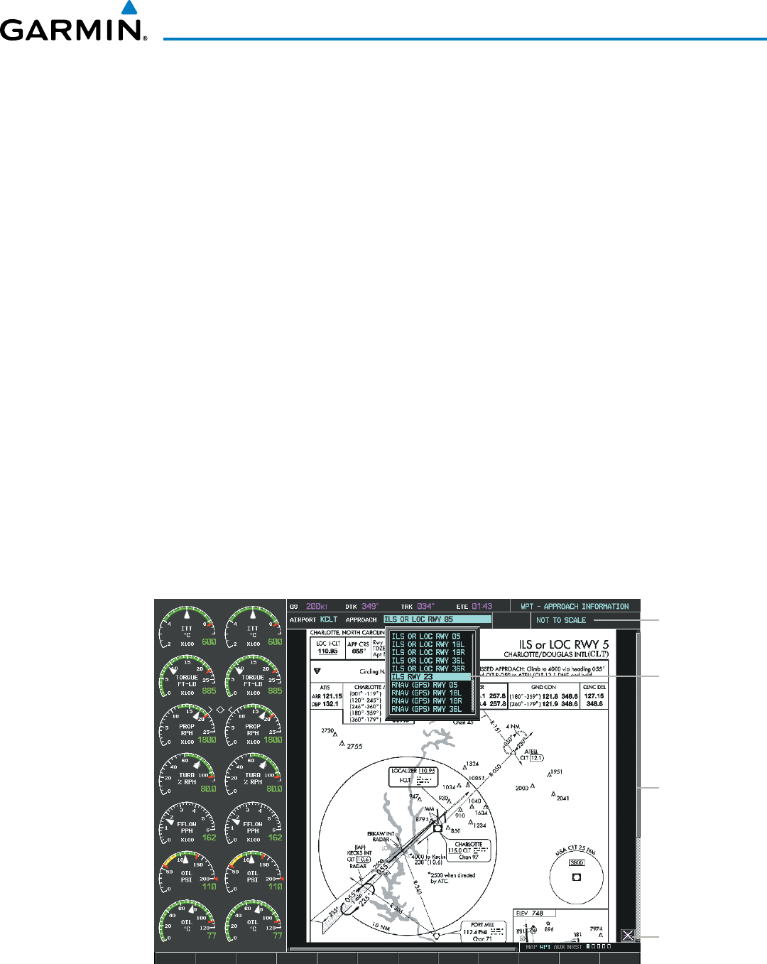
Garmin G1000 Pilot’s Guide for the Beechcraft 200/B200 Series
190-00928-04 Rev. A 591
ADDITIONAL FEATURES
When a chart is not available by selecting the SHW CHRT Softkey or selecting a Page Menu Option, charts
may be obtained for other airports from the WPT Pages or Flight Plan Pages.
If a chart is available for the destination airport, or the airport selected in the active flight plan, the chart
appears on the screen. When no flight plan is active, or when not flying to a direct-to destination, selecting the
SHW CHRT Softkey displays the chart for the nearest airport, if available.
The chart shown is one associated with the WPT – Airport Information page. Usually this is the airport runway
diagram. Where no runway diagram exists, but Take Off Minimums or Alternate Minimums are available, that
page appears. If Airport Information pages are unavailable, the Approach Chart for the airport is shown.
Selecting a chart:
1) While viewing the Navigation Map Page, Flight Plan Page, or Nearest Airports Page, select the SHW CHRT
Softkey. The airport diagram or approach chart is displayed on the Airport Information Page.
2) Press the
FMS
Knob to activate the cursor.
3) Turn the large FMS Knob to select either the Airport Identifier Box or the Approach Box. (Select the APR Softkey
if the Approach Box is not currently shown).
4) Turn the small and large FMS Knob to enter the desired airport identifier.
5) Press the ENT Key to complete the airport selection.
6) Turn the large FMS Knob to select the Approach Box.
7) Turn the small
FMS
Knob to show the approach chart selection choices.
8) Turn either
FMS
Knob to scroll through the available charts.
9) Press the ENT Key to complete the chart selection.
Figure 8-54 Approach Information Page, Chart Selection
Select Desired
Approach Chart
from Menu
Chart Not
To Scale
Pan Chart
With the
Joystick
Aircraft Not
Shown Icon
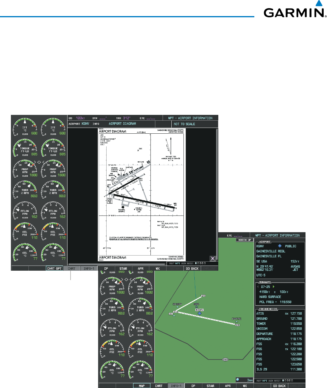
Garmin G1000 Pilot’s Guide for the Beechcraft 200/B200 Series
190-00928-04 Rev. A592
ADDITIONAL FEATURES
While the APPROACH Box is selected using the FMS Knob, the G1000 softkeys are blank. Once the desired
chart is selected, the chart scale can be changed and the chart can be panned using the Joystick. Pressing the
Joystick centers the chart on the screen.
The aircraft symbol is not shown on FliteCharts. The Chart Scale Box displays a banner NOT TO SCALE, and
the Aircraft Not Shown Icon is displayed in the lower right corner of the screen.
Selecting the CHRT Softkey switches between the FliteCharts diagram and the associated map in the WPT
page group. In the example shown, the CHRT Softkey switches between the Gainesville, FL (KGNV) Airport
Diagram and the navigation map on the WPT – Airport Information page.
Figure 8-55 CHRT Softkey, Airport Information Page
Select
CHRT
Softkey
to Switch Between
Navigation Map Page
and FliteCharts
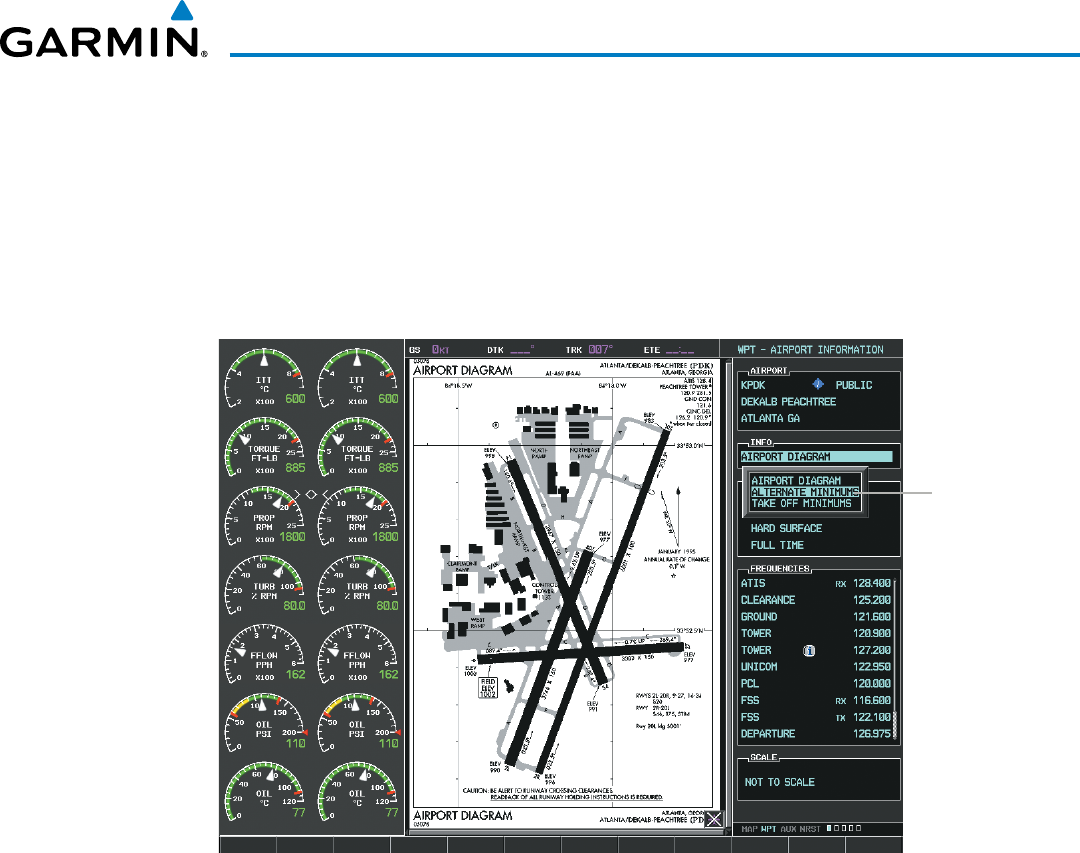
Garmin G1000 Pilot’s Guide for the Beechcraft 200/B200 Series
190-00928-04 Rev. A 593
ADDITIONAL FEATURES
Selecting the INFO-1 or INFO-2 Softkey returns to the airport diagram when the view is on a different chart.
If the displayed chart is the airport diagram, the INFO-1 or INFO-2 Softkey has no effect.
Another source for additional airport information is from the INFO Box above the chart (Figure 8-62) or to
the right of the chart (Figure 8-56) for certain airports. This information source is not related to the INFO-1 or
INFO-2 Softkey. When the INFO Box is selected using the FMS Knob, the G1000 softkeys are blank. The DeKalb
Peachtree Airport has three additional charts offering information; the Airport Diagram, Alternate Minimums, and
Take-off Minimums.
Figure 8-56 Airport Information Page, INFO View with Airport Information
Info Box
Selected
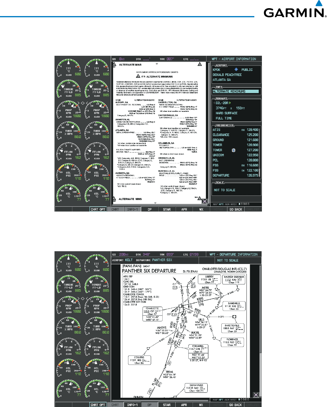
Garmin G1000 Pilot’s Guide for the Beechcraft 200/B200 Series
190-00928-04 Rev. A594
ADDITIONAL FEATURES
In the example shown in Figure 8-56, ALTERNATE MINIMUMS is selected. Pressing the ENT Key displays
the IFR Alternate Minimums Chart (Figure 8-57).
Figure 8-57 Airport Information Page, ALTERNATE MINIMUMS Selected from INFO View
Selecting the DP Softkey displays the Departure Procedure Chart if available.
Figure 8-58 Departure Information Page
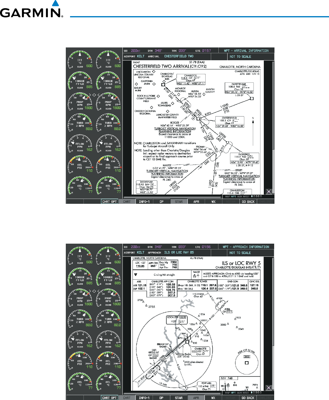
Garmin G1000 Pilot’s Guide for the Beechcraft 200/B200 Series
190-00928-04 Rev. A 595
ADDITIONAL FEATURES
Selecting the STAR Softkey displays the Standard Terminal Arrival Chart if available.
Figure 8-59 Arrival Information Page
Selecting the APR Softkey displays the approach chart for the airport if available.
Figure 8-60 Approach Information Page
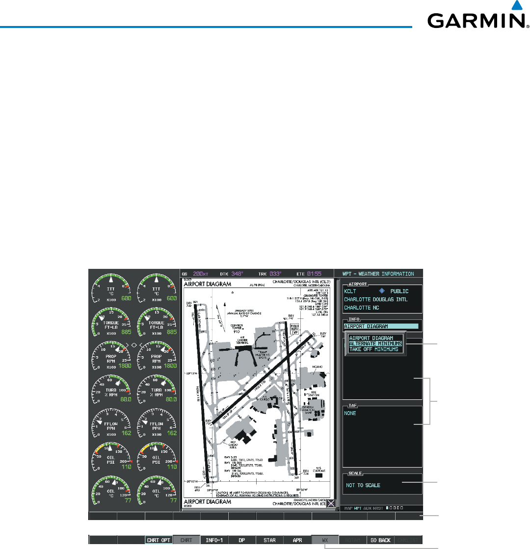
Garmin G1000 Pilot’s Guide for the Beechcraft 200/B200 Series
190-00928-04 Rev. A596
ADDITIONAL FEATURES
Selecting the WX Softkey shows the airport weather frequency information, when available, and includes
weather data such as METAR and TAF from the SiriusXM Data Link Receiver. Weather information is available
only when a SiriusXM Data Link Receiver is installed and the SiriusXM Weather subscription is current.
Selecting Additional Information:
1) While viewing the Airport Taxi Diagram, select the WX Softkey to display the information windows (AIRPORT,
INFO).
2) Press the
FMS
Knob to activate the cursor.
3) Turn the large
FMS
Knob to highlight the INFO Box.
4) Turn the small
FMS
Knob to select the INFO Box choices. When the INFO Box is selected the G1000 softkeys
are blank. If multiple choices are available, scroll to the desired choice with the large
FMS
Knob and press the
ENT Key to complete the selection.
5) Press the
FMS
Knob again to deactivate the cursor.
Figure 8-61 Weather Information Page, WX Softkey Selected
WX
Softkey
Selected
Softkeys are
Blank during
Info Box
Selection
Chart Not
To Scale
Info Available
on This
Airport
WX Info
When
Available
Selecting the GO
BACK Softkey reverts to the previous page (Navigation Map Page or Flight Plan Page).
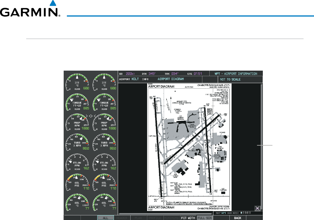
Garmin G1000 Pilot’s Guide for the Beechcraft 200/B200 Series
190-00928-04 Rev. A 597
ADDITIONAL FEATURES
CHART OPTIONS
Selecting the CHRT OPT Softkey displays the next level of softkeys, the chart options level (Figure 8-50).
Selecting the ALL Softkey shows the complete chart on the screen.
Complete
Chart
Shown
Figure 8-62 Airport Information Page, ALL View Selected
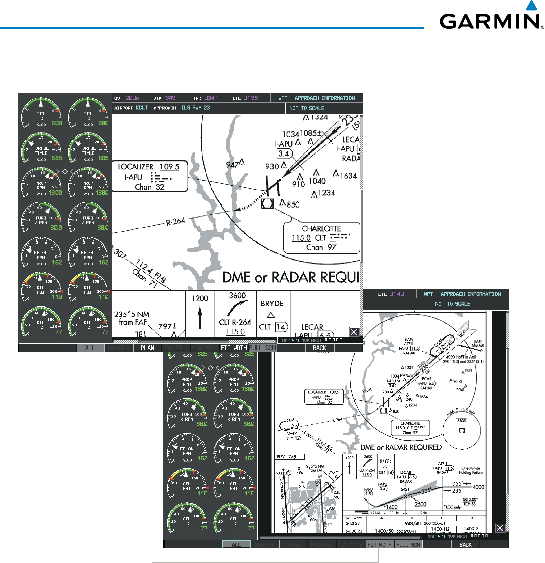
Garmin G1000 Pilot’s Guide for the Beechcraft 200/B200 Series
190-00928-04 Rev. A598
ADDITIONAL FEATURES
Selecting the FIT WIDTH Softkey fits the width of the chart in the display viewing area. In the example
shown, the chart at close range is replaced with the full width chart.
Figure 8-63 Approach Information Page, FIT WDTH Softkey Selected
Select
FIT WDTH
Softkey to Show
Full Chart Width
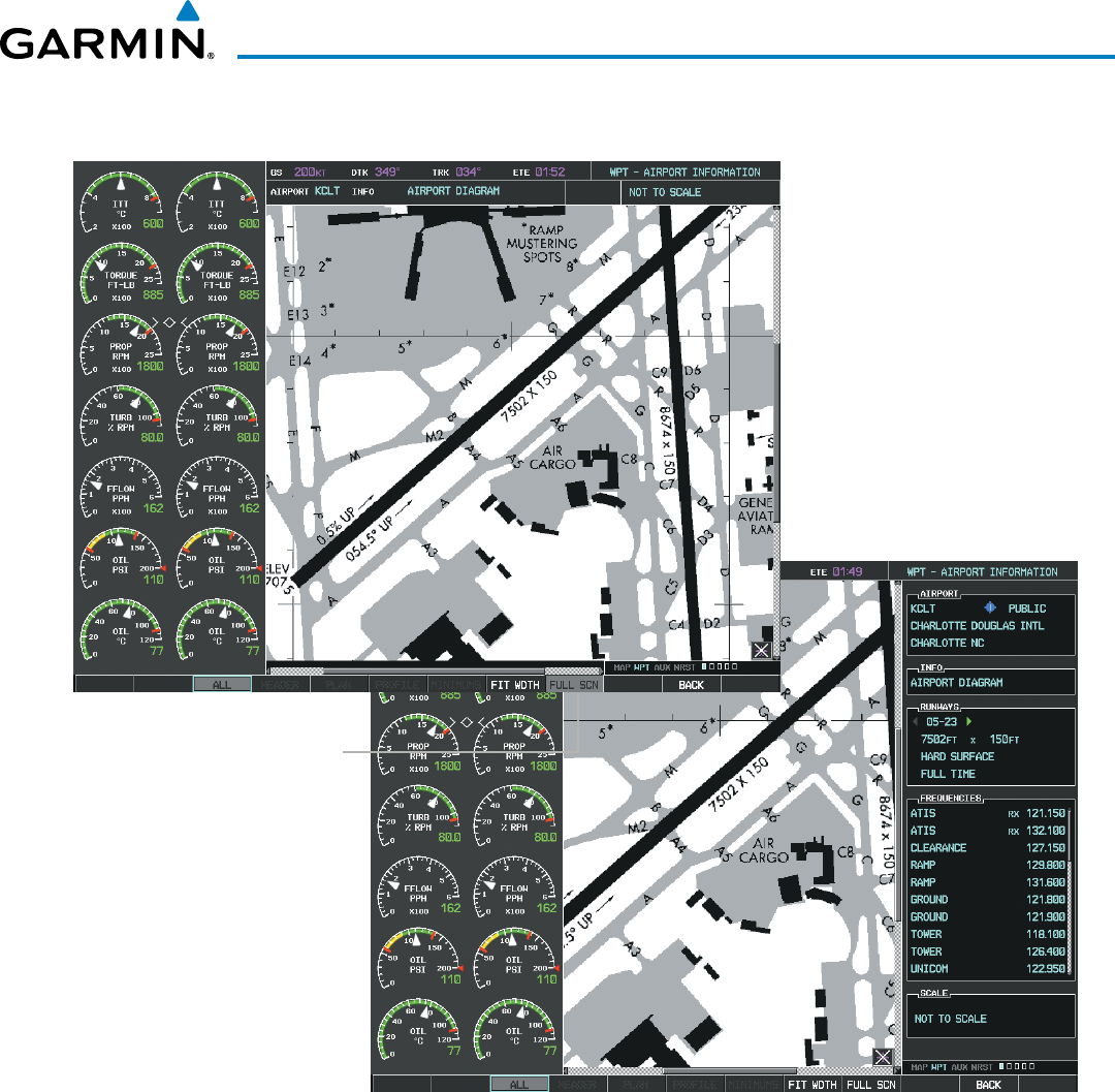
Garmin G1000 Pilot’s Guide for the Beechcraft 200/B200 Series
190-00928-04 Rev. A 599
ADDITIONAL FEATURES
Selecting the FULL
SCN Softkey alternates between removing and replacing the data window to the right.
Figure 8-64 Airport Information Page, Full Screen and Info Window
Select
FULL SCN
Softkey to Switch
Between Chart on
Full Screen and Chart
with Info Window
Selecting the BACK Softkey, or waiting for 45 seconds reverts to the chart selection softkeys.
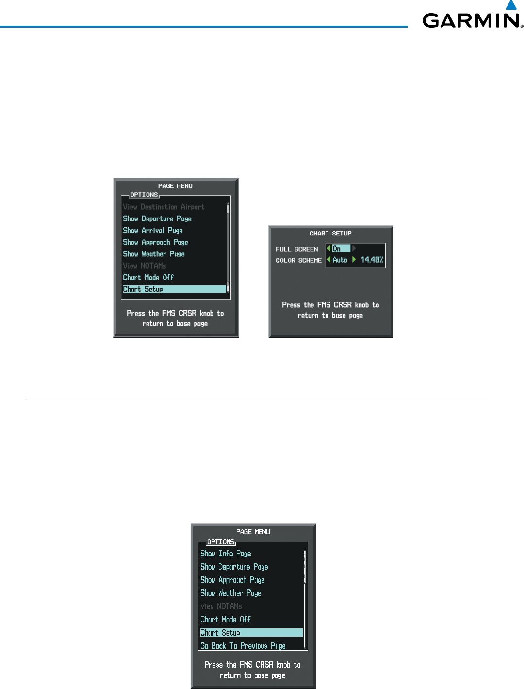
Garmin G1000 Pilot’s Guide for the Beechcraft 200/B200 Series
190-00928-04 Rev. A600
ADDITIONAL FEATURES
The full screen view can also be selected by using the page menu option.
Selecting full screen On or Off:
1) While viewing a terminal chart press the MENU Key to display the Page Menu OPTIONS.
2) Turn the large
FMS
Knob to highlight the Chart Setup Menu Option and press the
ENT
Key.
3) Turn the large
FMS
Knob to move between the FULL SCREEN and COLOR SCHEME Options.
4) Turn the small
FMS
Knob to choose between the On and Off Full Screen Options.
Figure 8-65 Page Menus
Full Screen On/Off SelectionChart Setup Option
DAY/NIGHT VIEW
FliteCharts can be displayed on a white or black background for day or night viewing. The Day View offers
a better presentation in a bright environment. The Night View gives a better presentation for viewing in a dark
environment. When the CHART SETUP Box is selected the MFD softkeys are blank.
Selecting Day, Night, or Automatic View:
1) While viewing a terminal chart press the MENU Key to display the Page Menu OPTIONS.
2) Turn the large
FMS
Knob to highlight the Chart Setup Menu Option and press the
ENT
Key.
Figure 8-66 Waypoint Information Page, OPTIONS Menu
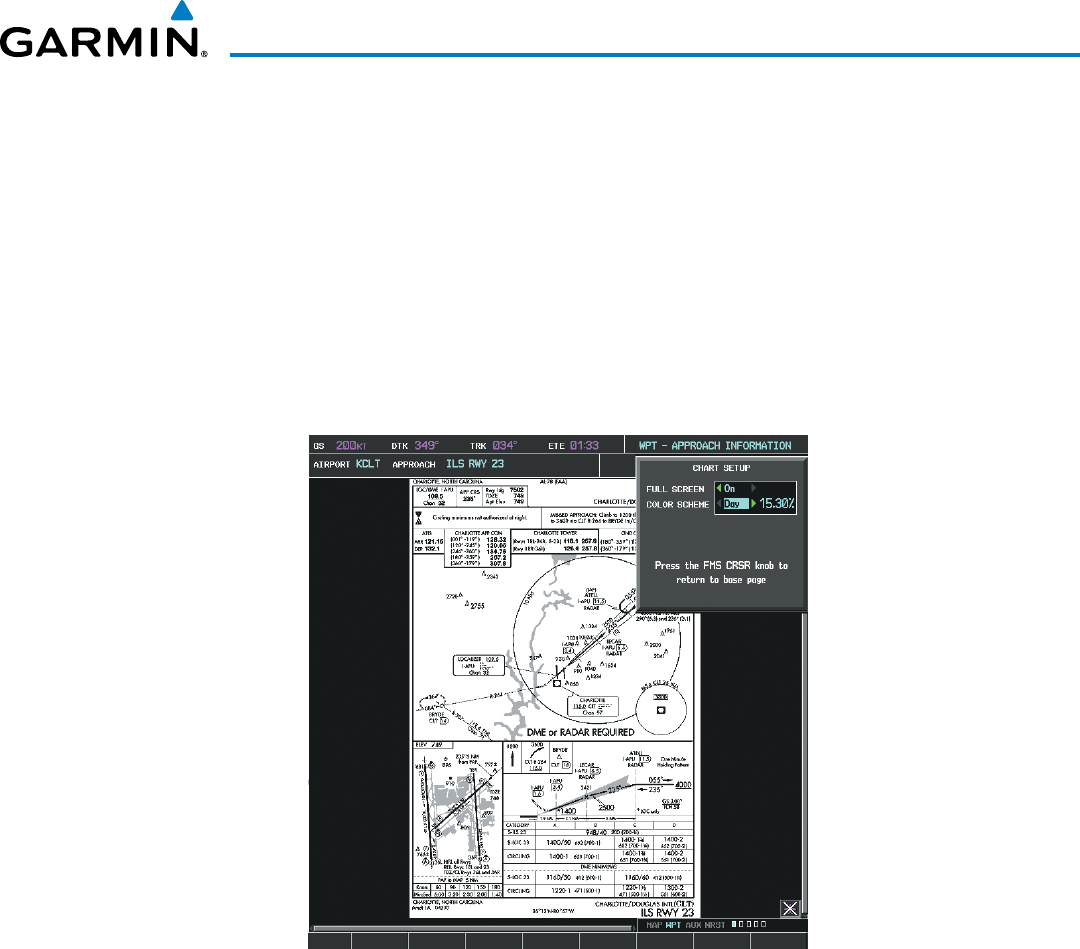
Garmin G1000 Pilot’s Guide for the Beechcraft 200/B200 Series
190-00928-04 Rev. A 601
ADDITIONAL FEATURES
3) Turn the large
FMS
Knob to move to the COLOR SCHEME Option (Figure 8‑67).
4) Turn the small
FMS
Knob to choose between Day, Auto, and Night Options.
5) If Auto Mode is selected, turn the large FMS Knob to select the percentage field. Use the small FMS Knob to
change the percentage value. The percentage value is the day/night crossover point based on the percentage of
backlighting intensity. For example, if the value is set to 15%, the day/night display changes when the display
backlight reaches 15% of full brightness.
The display must be changed in order for the new setting to become active. This may be accomplished by
selecting another page or changing the display range.
6) Press the FMS Knob when finished to remove the Chart Setup Menu.
Figure 8-67 Approach Information Page, Day View
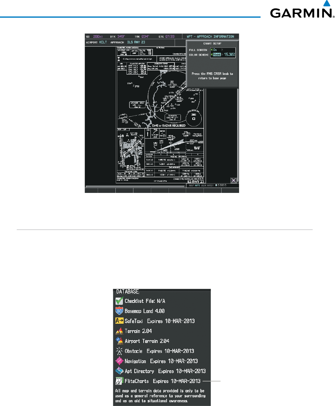
Garmin G1000 Pilot’s Guide for the Beechcraft 200/B200 Series
190-00928-04 Rev. A602
ADDITIONAL FEATURES
Figure 8-68 Approach Information Page, Night View
FLITECHARTS CYCLE NUMBER AND EXPIRATION DATE
FliteCharts data is revised every 28 days. Charts are still viewable during a period that extends from the cycle
expiration date to the disables date. FliteCharts is disabled 180 days after the expiration date and are no longer
available for viewing upon reaching the disables date. When turning on the system, the Power-up Page displays
the current status of the FliteCharts database. See the table below for the various FliteCharts Power-up Page
displays and the definition of each.
Figure 8-69 Power-up Page, FliteCharts Database
FliteCharts Database
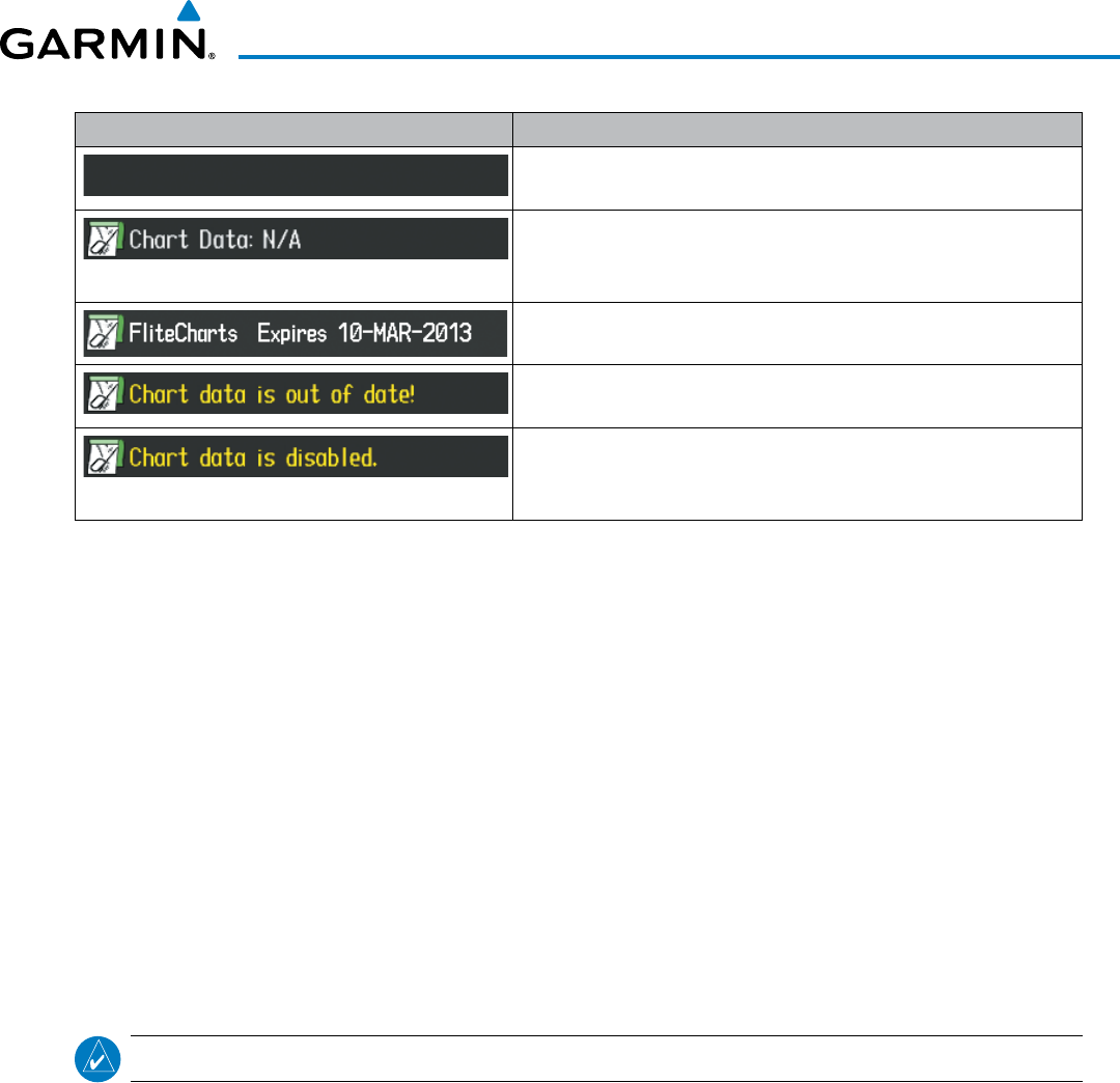
Garmin G1000 Pilot’s Guide for the Beechcraft 200/B200 Series
190-00928-04 Rev. A 603
ADDITIONAL FEATURES
Power-up Page Display Definition
Blank Line. system is not configured for FliteCharts. Contact a Garmin‑
authorized service center for configuration.
System is configured for FliteCharts but no chart database is installed.
Refer to Updating Garmin Databases in Appendix B for the FliteCharts
database
Normal operation. FliteCharts database is valid and within current
cycle.
FliteCharts database is beyond the expiration date, but still within the
180 day viewing period.
FliteCharts database has timed out. Database is beyond 180 days
after expiration date. FliteCharts database is no longer available for
viewing.
Table 8-3 FliteCharts Power-up Page Annunciations and Definitions
Other possible AUX - System Status page conditions are shown in Figure 8-70. ‘FliteCharts Expires’ plus a
date in white, indicates the chart database is current. ‘Chart data is out of date!’ in yellow, indicates charts are
still viewable, but approaching the disable date.
When the 180 day grace period has expired, ‘Chart data is disabled.’ in yellow indicates that the FliteCharts
database has expired and is no longer viewable. ‘Chart Data: N/A’ appears in white if no FliteCharts data is
available on the database card or no database card is inserted.
FliteCharts time critical information can also be found on the AUX - System Status page. The FliteCharts
database REGION, CYCLE number, EFFECTIVE, EXPIRES, and DISABLES dates of the subscription appear in
either blue or yellow text. Dates shown in blue are current data. Dates shown in yellow indicate the data is not
within the current subscription period.
FliteCharts becomes inoperative 180 days after the FliteCharts EXPIRES date is reached, and is no longer
available for viewing. This date is shown as the DISABLES date. After the disable date the
SHW CHRT
Softkey
label appears subdued and is unavailable until a revised issue of FliteCharts is installed.
NOTE
: A subdued softkey label indicates the function is disabled.
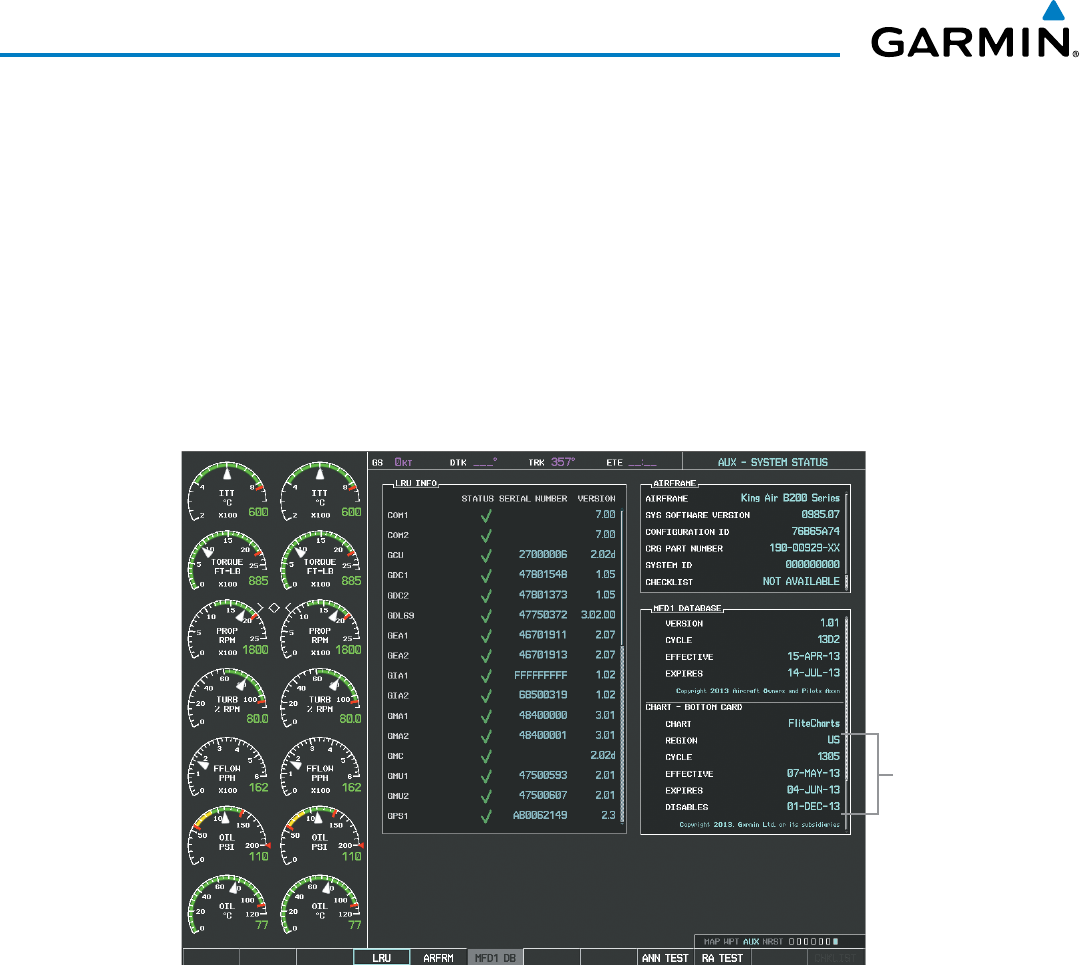
Garmin G1000 Pilot’s Guide for the Beechcraft 200/B200 Series
190-00928-04 Rev. A604
ADDITIONAL FEATURES
Select the MFD1 DB Softkey to place the cursor in the DATABASE window. Scroll through the listed
information by turning the FMS Knob or pressing the ENT Key until the FliteCharts database information is
shown.
The FliteCharts database cycle number shown in the figure, 1305, is deciphered as follows:
13 – Indicates the year 2013
05 – Indicates the fifth issue of the FliteCharts database for the year
The FliteCharts EFFECTIVE date 07–MAY–13 is the first date that this database is current.
The FliteCharts EXPIRES date 04–JUN–13 is the last date that this database is current.
The DISABLES date 01–DEC–13 is the date that this database becomes inoperative.
Figure 8-70 AUX – System Status Page, FliteCharts Current and Available
FliteCharts
Data
The FliteCharts database is provided from Garmin. Refer to Updating Garmin Databases in Appendix B for
instructions on revising the FliteCharts database.
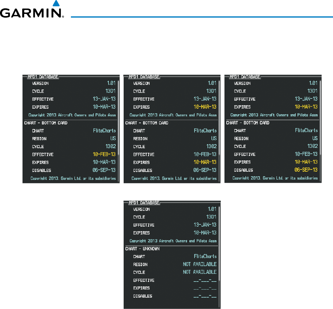
Garmin G1000 Pilot’s Guide for the Beechcraft 200/B200 Series
190-00928-04 Rev. A 605
ADDITIONAL FEATURES
The other three possible AUX - System Status page conditions are shown here. The EXPIRES date, in yellow,
is the revision date for the next database cycle. The DISABLES date, in yellow, is the date that this database cycle
is no longer viewable. REGION and CYCLE NOT AVAILABLE in blue, indicate that FliteCharts database is not
available on the database card or no database card is inserted.
Figure 8-71 AUX – System Status Page, FliteCharts Datbase Status
FliteCharts Expired, but is not Disabled FliteCharts Database is Disabled
FliteCharts Database is Not Available
Current Date is Before Effective Date
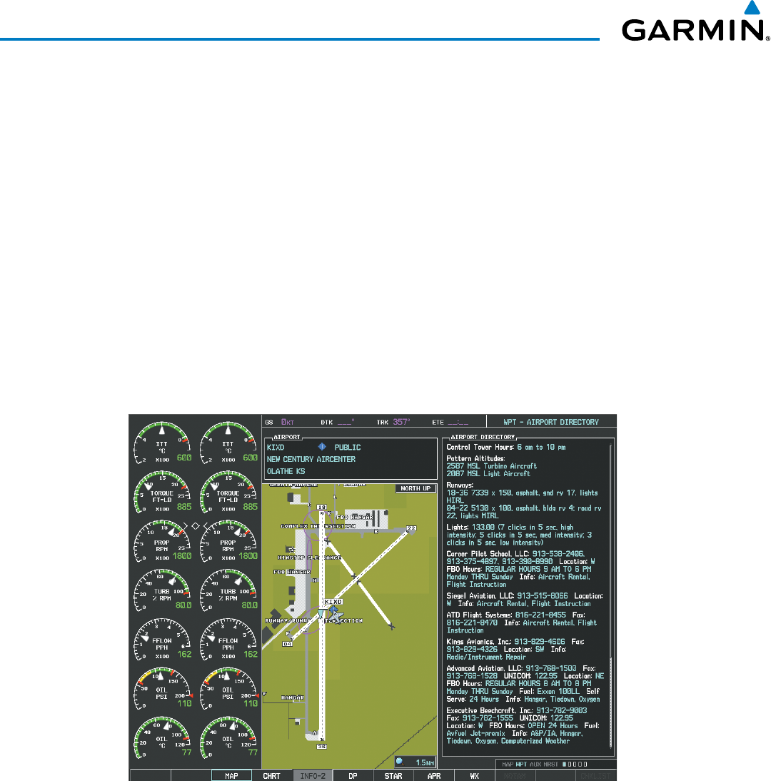
Garmin G1000 Pilot’s Guide for the Beechcraft 200/B200 Series
190-00928-04 Rev. A606
ADDITIONAL FEATURES
8.5 AIRPORT DIRECTORY
The Aircraft Owners and Pilots Association (AOPA) and optional AC-U-KWIK Airport Directory databases
offer detailed information regarding services, hours of operation, lodging options, and more. This information
is viewed on the Airport Information Page by selecting the INFO Softkey until INFO-2 is displayed as shown in
Figure 8-72.
Both Airport Directories are available for downloading at flygarmin.com. However, copy only one of the
databases to the Supplemental Data Card. The system cannot recognize both databases simultaneously.
Selecting the Airport Directory Page:
1) Turn the large
FMS
Knob to select the ‘WPT’ page group.
2) Turn the small
FMS
Knob to select the AIRPORT INFORMATION Page. Initially, information for the airport closest
to the aircraft’s present position is displayed.
3) If necessary, select the INFO softkey until INFO-2 is displayed.
Figure 8-72 AOPA Information on the Airport Information Page
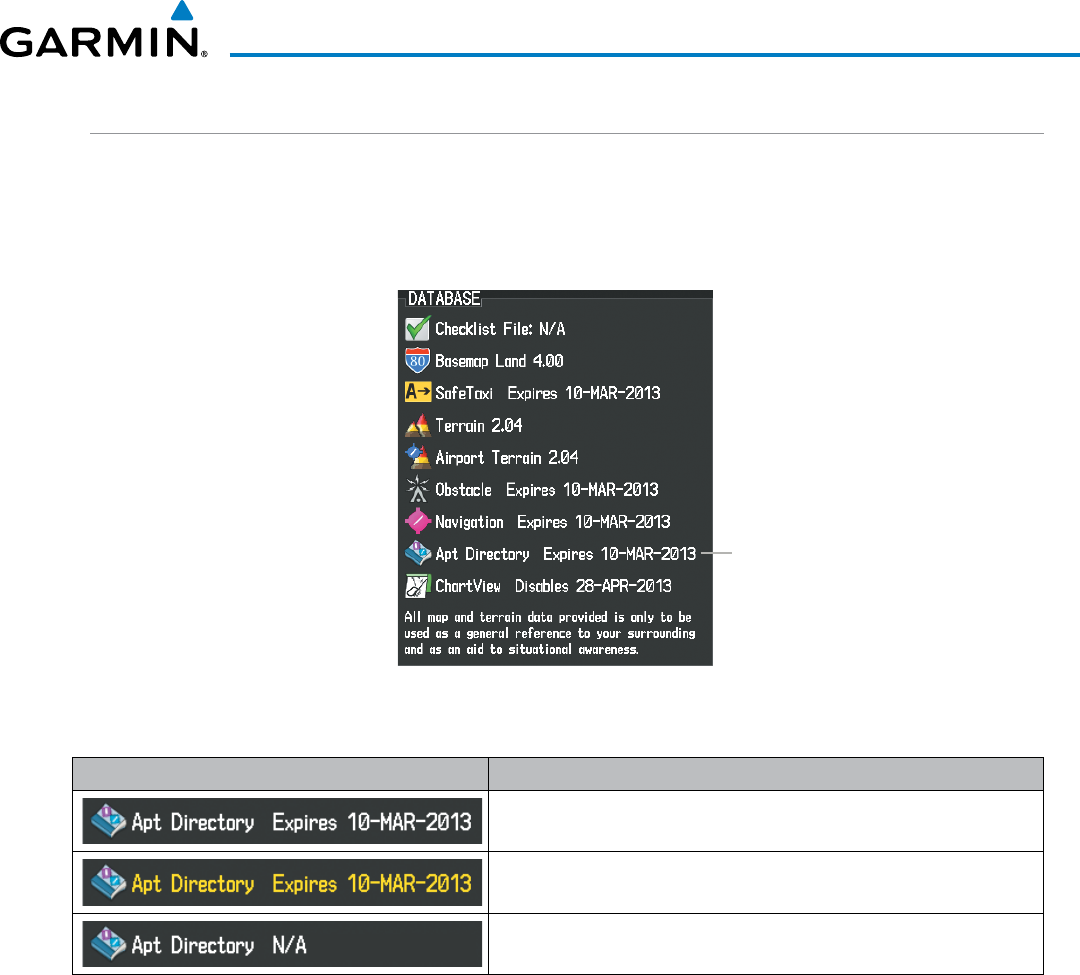
Garmin G1000 Pilot’s Guide for the Beechcraft 200/B200 Series
190-00928-04 Rev. A 607
ADDITIONAL FEATURES
AIRPORT DIRECTORY DATABASE CYCLE NUMBER AND REVISION
The Airport Directory databases are revised every 56 days and offered on a subscription basis. Check fly.
garmin.com for the current database. The Airport Directory is always available for use after the expiration date.
When turning on the system, the Power-up Page indicates whether the databases are current, out of date, or
not available.
Figure 8-73 Power-up Page, Airport Directory Database
Airport Directory Database
Power-up Page Display Definition
Normal operation. Airport Directory database is valid and within
current cycle.
Airport Directory database has expired.
Database card contains no Airport Directory data.
Table 8-4 Airport Directory Annunciation Definitions
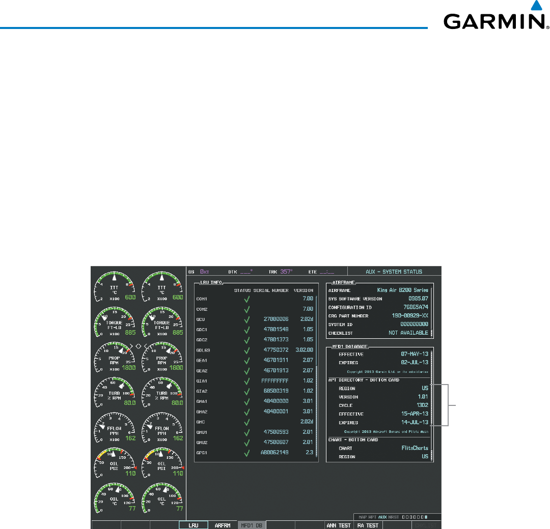
Garmin G1000 Pilot’s Guide for the Beechcraft 200/B200 Series
190-00928-04 Rev. A608
ADDITIONAL FEATURES
The Airport Directory Region, Version, Cycle, Effective date and Expires date of the database cycle can also be
found on the AUX - System Status page, as seen in Figure 8-74.
Select the MFD1 DB Softkey to place the cursor in the DATABASE window. Scroll through the listed
information by turning the FMS Knob or pressing the ENT Key until the Airport Directory database information
is shown.
The Airport Directory database cycle number shown in the figure, 11D2, is deciphered as follows:
11 – Indicates the year 2011
D – Indicates the data is for Airport Directory
2 – Indicates the second issue of the Airport Directory database for the year
The Airport Directory EFFECTIVE date 15–APR–11 is the beginning date for the current database cycle. The
Airport Directory EXPIRES date 14–JUL–11 is the revision date for the next database cycle.
Figure 8-74 AUX – System Status Page, Airport Directory Current Information
Airport Directory
Data
Airport Directory information appears in blue and yellow text. The EFFECTIVE date appears in blue when
data is current and in yellow when the current date is before the effective date. The EXPIRES date appears in
blue when data is current and in yellow when expired (Table 8-4). NOT AVAILABLE appears in blue in the
REGION field if Airport Directory data is not available on the database card. An expired Airport Directory
database is not disabled and will continue to function indefinitely.
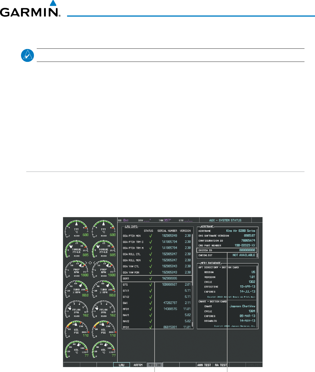
Garmin G1000 Pilot’s Guide for the Beechcraft 200/B200 Series
190-00928-04 Rev. A 609
ADDITIONAL FEATURES
8.6 SATELLITE TELEPHONE
NOTE
: An account must be established to access the Iridium satellite network for voice/SMS.
The GSR 56 Iridium Transceiver provides an airborne low speed data link, Iridium Satellite Telephone service,
and Short Message Service (SMS). The GSR 56 can also be paired with the optional GDL 59 Data Link, providing
a high speed (IEEE 802.11g) Wi-Fi data link between the aircraft and a ground computer network while the
aircraft is on the ground.
The telephone is available to the flight crew through the audio panel and headsets. An optional handset may be
installed in the aircraft cabin to be used for voice communication between the aircraft cabin and the cockpit and
for Iridium telephone service in the aircraft cabin.
Operation of these features in the cockpit is accomplished through the AUX-TELEPHONE, AUX-TEXT
MESSAGING, and AUX-WI-FI SETUP Pages. For operation using the cabin handset, consult the instructions
provided with the handset.
REGISTERING WITH GARMIN CONNEXT
™
A subscriber account must be established prior to using the Iridium Satellite System. Before setting up an
Iridium account, obtain the serial number of the Iridium Transceiver (GSR1) and the System ID by selecting the
AUX- SYSTEM STATUS Page as shown in Figure 8-75. Contact Garmin at 1-866-739-5687 in the United States
or 913-397-8200, ext. 1135.
Figure 8-75 Identification Needed for Iridium Registration
Iridium Transceiver Serial Number System ID Number
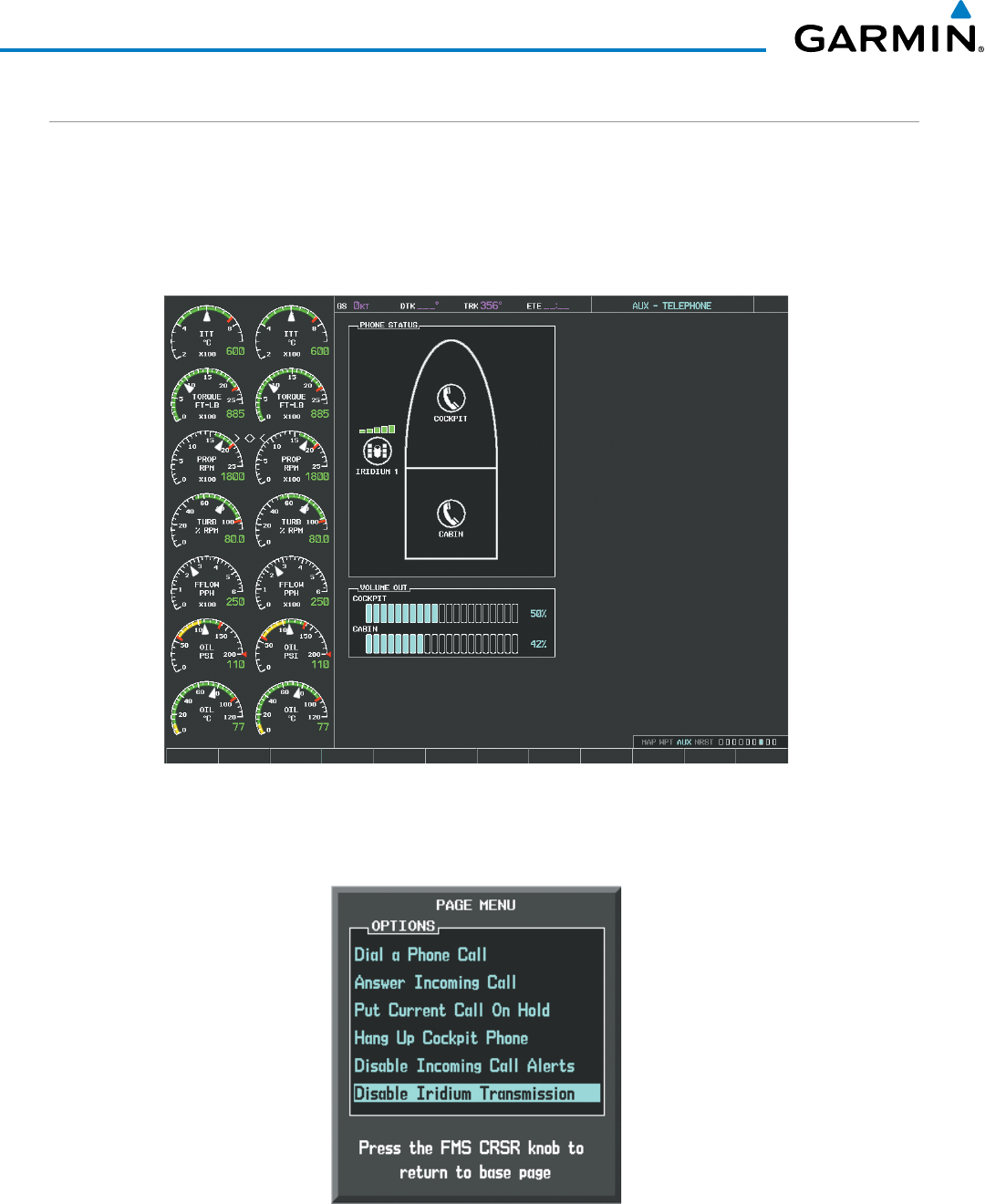
Garmin G1000 Pilot’s Guide for the Beechcraft 200/B200 Series
190-00928-04 Rev. A610
ADDITIONAL FEATURES
DISABLE/ENABLE IRIDIUM TRANSCEIVER
Iridium telephone and data communications may be turned on or off by performing these simple steps.
Disabling/enabling telephone and low speed data services:
1) Turn the large FMS Knob on the MFD to select the AUX page group.
2) Turn the small FMS Knob to select the AUX‑TELEPHONE Page as in Figure 8‑76.
Figure 8-76 Report Status Page
3) Press the MENU Key. The Page Menu window is now displayed as seen in Figure 8‑77.
4) Turn the FMS Knob to select ‘Disable Iridium Transmission’ in the menu list.
Figure 8-77 Select Disable Iridium Transmission
5) Press the ENT Key. The Iridium transceiver is now disabled.
6) To enable the Iridium transceiver, repeat steps 1 through 3, then select ‘Enable Iridium Transceiver’.
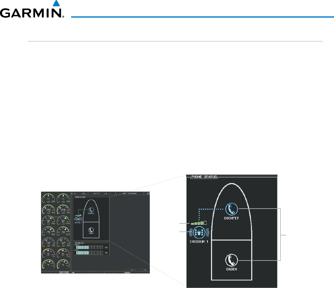
Garmin G1000 Pilot’s Guide for the Beechcraft 200/B200 Series
190-00928-04 Rev. A 611
ADDITIONAL FEATURES
TELEPHONE COMMUNICATION
The pilot or copilot can place and answer calls on the Iridium satellite network as well as to or from the
telephone handset in the cabin. Calls can also be answered or made from the optional cabin phone, however,
only actions initiated from the cockpit will be discussed here. See the cabin handset user guide for more
information. Control and monitoring of telephone functions are accomplished through the AUX-TELEPHONE
Page.
Viewing the Telephone Page:
1) Turn the large FMS Knob on the MFD to select the AUX page group.
2) Turn the small FMS Knob to select the AUX ‑ TELEPHONE or AUX ‑ TEXT MESSAGING Page.
3) If necessary, select the TEL Softkey to display the AUX‑TELEPHONE Page.
The phone status display, as shown in Figure 8-78, gives a graphical representation of the current disposition
of voice and/or data transmissions. Table 8-5 describes symbology used on Phone Status display.
Figure 8-78 Phone Status Display
Internal
Phones
Satellite
Signal
Strength
External
Phone
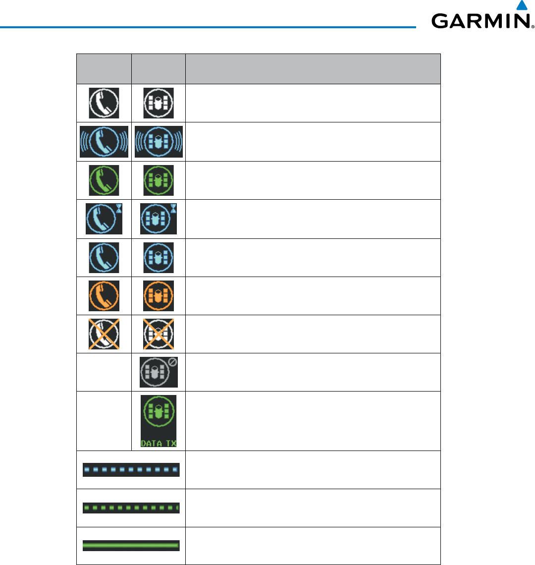
Garmin G1000 Pilot’s Guide for the Beechcraft 200/B200 Series
190-00928-04 Rev. A612
ADDITIONAL FEATURES
Internal
Phone
External
Phone Description
Phone is Idle
Phone is ringing
Phone has a dial tone (off hook) or connected to another phone
Phone dialed is busy
Phone is dialing another phone
Phone has failed
Phone status not known
Phone is disabled
Phone is reserved for data transmission
Calling other phone or incoming call from other phone
Other phone is on hold
Phones are connected
Table 8-5 Telephone Symbols
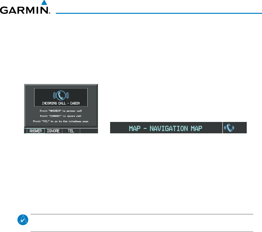
Garmin G1000 Pilot’s Guide for the Beechcraft 200/B200 Series
190-00928-04 Rev. A 613
ADDITIONAL FEATURES
INCOMING CALLS
When viewing MFD pages other than the AUX-TELEPHONE Page, a pop-up alert similar to Figure 8-79
will be displayed and an aural alert “Incoming Call” will be heard. If the call is from the cabin, CABIN will be
displayed as seen in Figure 8-79. If the incoming call is an Iridium network call, IRIDIUM will be displayed.
The pop-up alert may be inhibited at times, such as during takeoff. In addition to the pop-up alert, a ringing
phone symbol will be displayed to the right of the MFD page title as shown in Figure 8-79. Also, the voice
alert “Incoming Call” will be heard on the selected cockpit audio.
Figure 8-79 Incoming Call
Incoming Call Pop-up Incoming Call Symbol on MFD Page
Answering an incoming call in the cockpit:
1) Press the TEL Key on the appropriate audio panel.
2) Select the ANSWER Softkey on the MFD.
Or:
While viewing the AUX‑TELEPHONE Page
NOTE
: The Push-to-Talk switch is not utilized for telephone communication. The microphone is active after
selecting the ANSWER Softkey, and stays active until the call is terminated.
1) Press the TEL Key on the appropriate audio panel.
2) Press the MENU Key to display the Page Menu.
3) Turn either FMS Knob to place the cursor on ‘Answer Incoming Call’.
4) Press the ENT Key.
Selecting the IGNORE Softkey will extinguish the pop-up window and leave the call unanswered. Selecting
the TEL Softkey will display the AUX-TELEPHONE Page allowing additional call information to be viewed
before answering.
Muting incoming call alerts:
1) With the AUX‑TELEPHONE Page displayed, press the MENU Key on the MFD to display the Page Menu.
2) Turn either FMS Knob to place the cursor on ‘Mute Incoming Call Alerts’.
3) Press the ENT Key. The voice and pop‑up alert will not be displayed now when an incoming call is received.
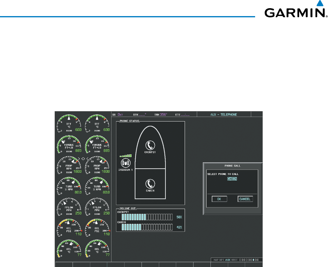
Garmin G1000 Pilot’s Guide for the Beechcraft 200/B200 Series
190-00928-04 Rev. A614
ADDITIONAL FEATURES
OUTGOING CALLS
Voice calls can be made from the cockpit to the handset in the cabin, or to an external phone through the
Iridium Satellite Network.
Making a call to the cabin:
1) Press the TEL Key on the appropriate audio panel.
2) Select the DIAL Softkey on the MFD. A display similar to Figure 8‑80 will be shown.
Figure 8-80 Initiating a Cabin Call
3) Press the ENT Key. The cursor will move from ‘CABIN’ to ‘OK’.
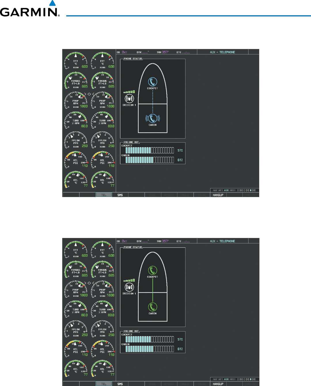
Garmin G1000 Pilot’s Guide for the Beechcraft 200/B200 Series
190-00928-04 Rev. A 615
ADDITIONAL FEATURES
4) Press the ENT Key again. The cabin phone will now ring as seen in Figure 8‑81.
Figure 8-81 Cabin Phone Ringing
When the cabin phone is answered, the connection is established as shown in Figure 8-82. To exit the call,
select the HANGUP Softkey.
Figure 8-82 Cabin Phone Answered
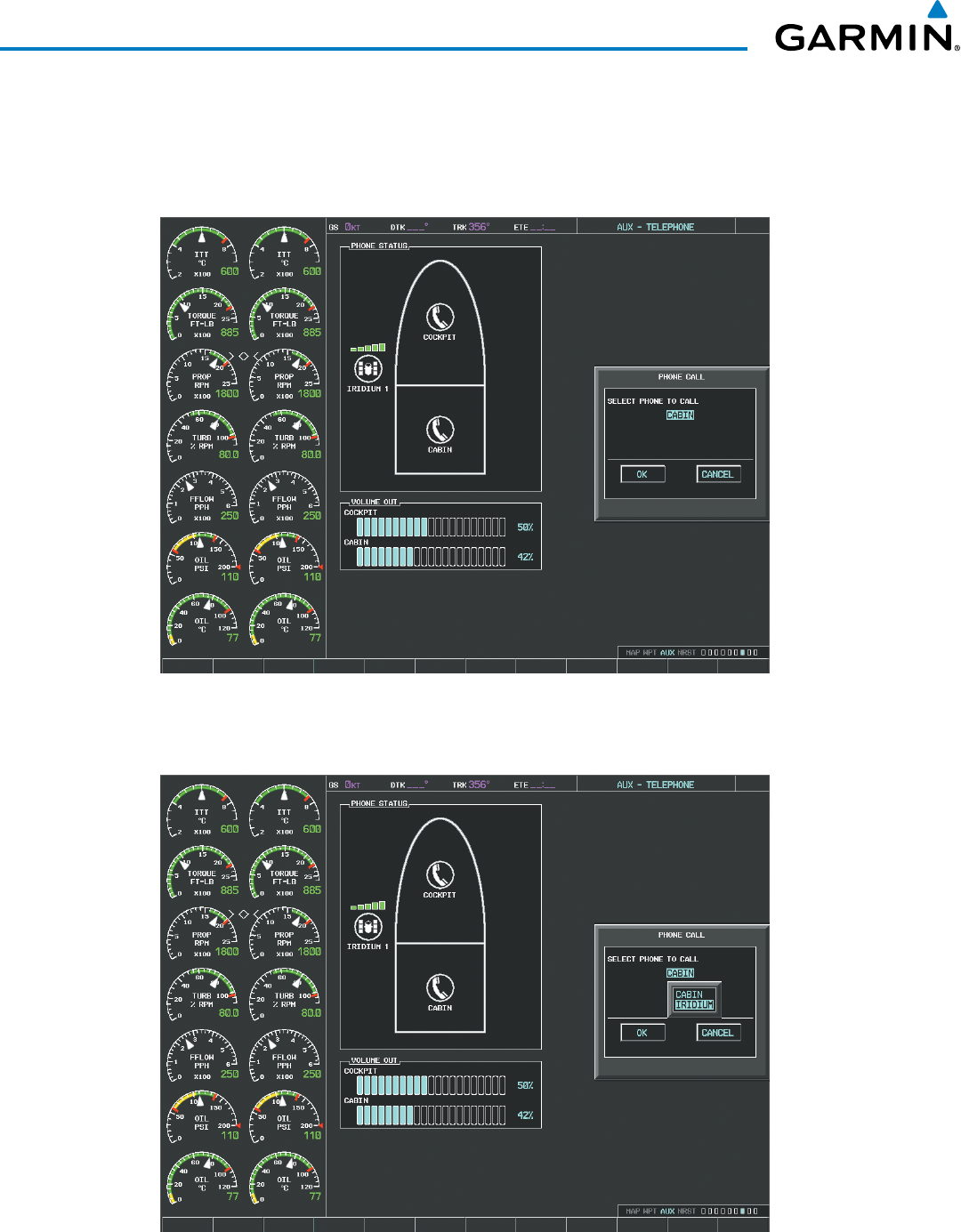
Garmin G1000 Pilot’s Guide for the Beechcraft 200/B200 Series
190-00928-04 Rev. A616
ADDITIONAL FEATURES
Making an external call from the cockpit using the Iridium satellite network:
1) Press the TEL Key on the appropriate audio panel.
2) Select the DIAL Softkey on the MFD. A display similar to Figure 8‑83 will be shown.
Figure 8-83 Initiating an External Call
3) Turn the small FMS Knob to select ‘IRIDIUM’ as seen in Figure 8‑84.
Figure 8-84 Selecting the Iridium Satellite System
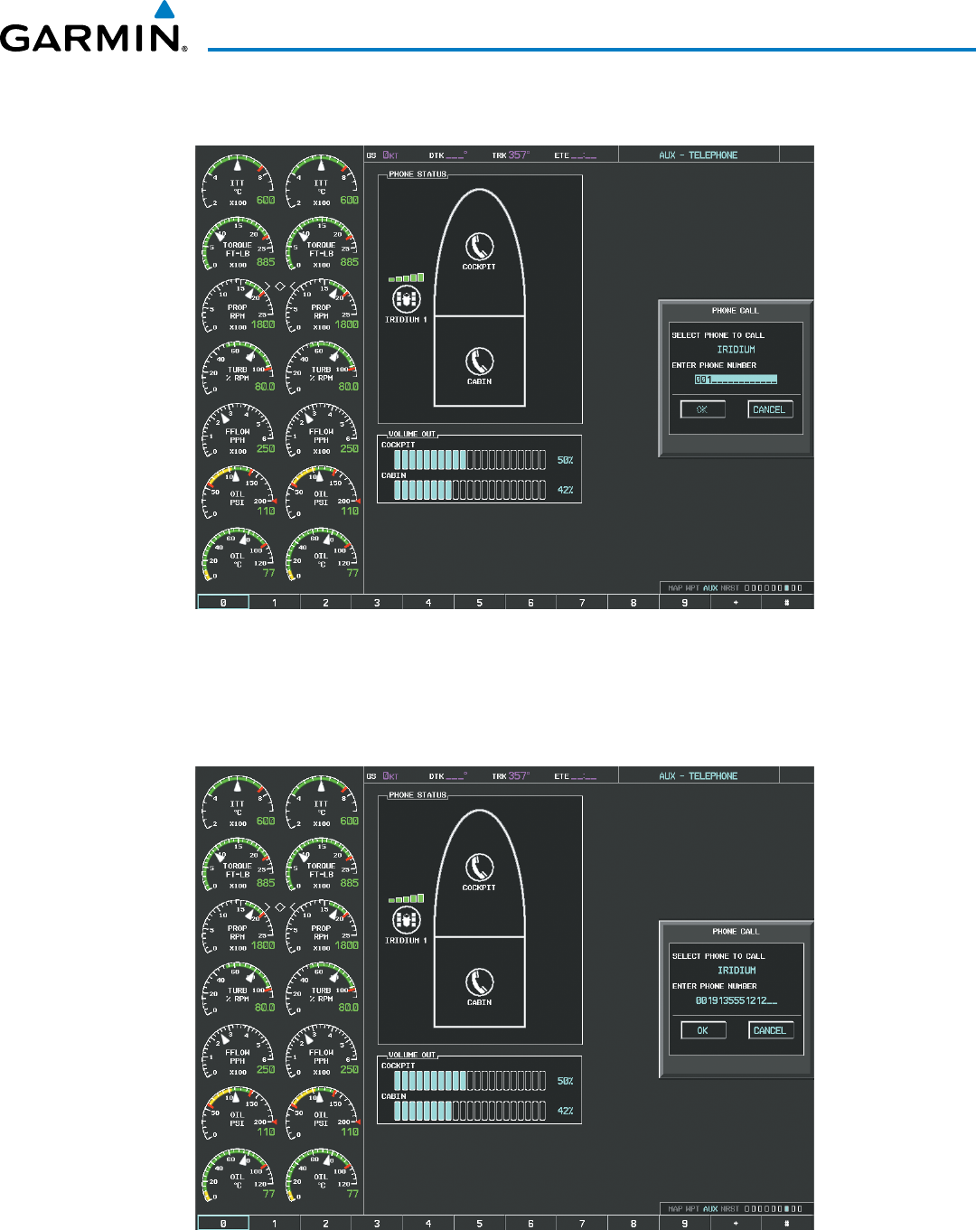
Garmin G1000 Pilot’s Guide for the Beechcraft 200/B200 Series
190-00928-04 Rev. A 617
ADDITIONAL FEATURES
4) Press the ENT Key. The cursor has now moved to the phone number entry field as shown in Figure 8‑85.
Figure 8-85 Enter Phone Number
5) Enter the desired telephone number (country code first) by selecting the number softkeys on the MFD or by
pressing the numeric keys on the MFD Control Unit.
6) Press the ENT Key. ‘OK’ is highlighted as in Figure 8‑86.
Figure 8-86 Make the Call
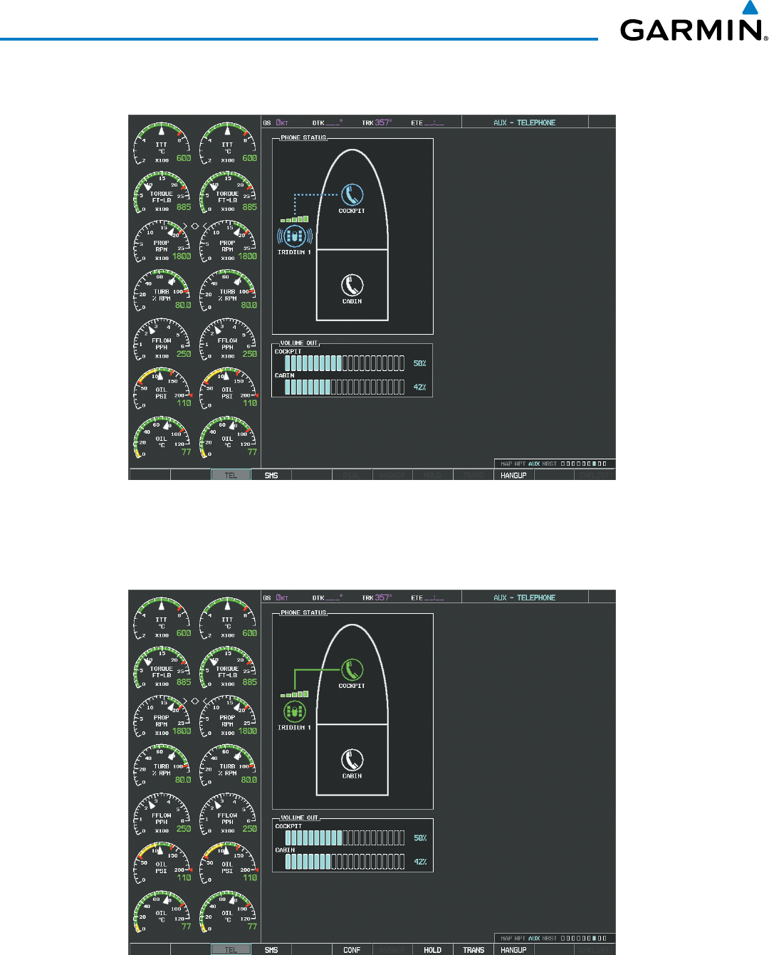
Garmin G1000 Pilot’s Guide for the Beechcraft 200/B200 Series
190-00928-04 Rev. A618
ADDITIONAL FEATURES
7) Press the ENT Key. The system will begin calling the number, as in Figure 8‑87.
Figure 8-87 System is Making the Connection
When the phone is answered, the connection is established as shown in Figure 8-88. To exit the call, select
the HANGUP Softkey.
Figure 8-88 Phone is Answered, Connection Complete
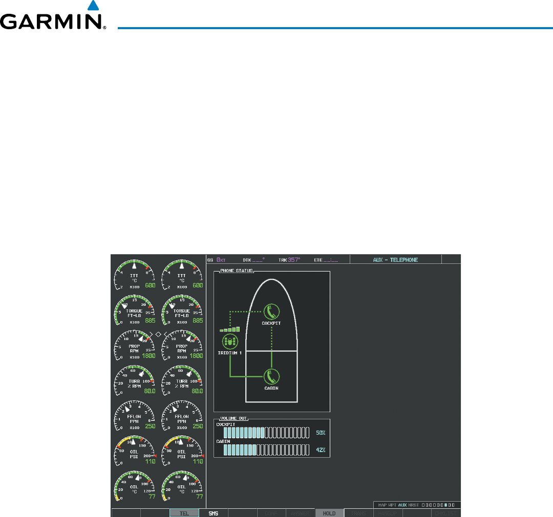
Garmin G1000 Pilot’s Guide for the Beechcraft 200/B200 Series
190-00928-04 Rev. A 619
ADDITIONAL FEATURES
PLACING THE COCKPIT PHONE ON HOLD
Placing a call on hold:
Select the HOLD Softkey on the MFD.
Or:
1) Press the MENU Key to display the Page Menu.
2) Turn either FMS Knob to place the cursor on ‘Put Current Call On Hold’.
3) Press the ENT Key.
The cockpit phone is now isolated from the call as seen in Figure 8-89. This figure illustrates a conference
call between the cockpit, cabin, and an external phone in which the cockpit phone has been put on hold.
Select the HOLD Softkey again to resume the call.
Figure 8-89 Cockpit Phone on Hold
TRANSFERRING A CALL FROM THE COCKPIT
From the cockpit phone, a external call can be transferred to the cabin phone, or a call with the cabin phone
can be transferred to an external phone, or (when two Iridium Transceivers are installed) an external call can
be transferred to another external phone.
Transfering a call:
1) Select the TRANS Softkey on the MFD.
Or:
a) Press the MENU Key to display the Page Menu.
b) Turn either FMS Knob to place the cursor on ‘Transfer Current Call’.
c) Press the ENT Key.
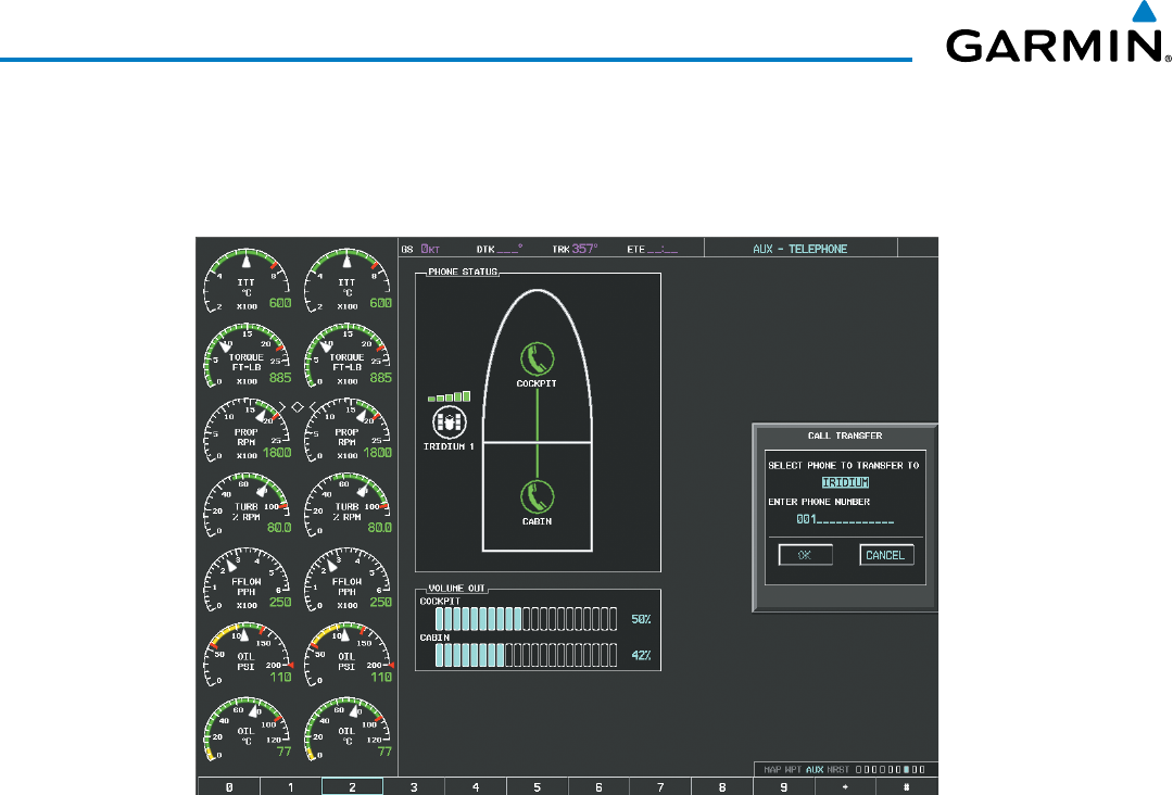
Garmin G1000 Pilot’s Guide for the Beechcraft 200/B200 Series
190-00928-04 Rev. A620
ADDITIONAL FEATURES
A window similar to that shown in Figure 8-90 will be displayed. In this example, an active call to the cabin
is transferred to an external number. Therefore, the window shows the ‘Iridium’ option. If the active call is
with an external phone, ‘CABIN’ would be the option.
Figure 8-90 Enter Phone Number to Receive Transferred Call
2) Press the ENT Key. The cursor now highlights the phone number entry field.
3) Enter the phone number to which the call is being transferred, as discussed earlier for making an external call
on the Iridium satellite network.
4) Press the ENT Key. ‘OK’ is now highlighted.
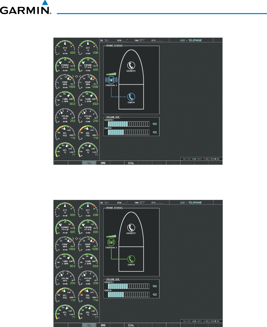
Garmin G1000 Pilot’s Guide for the Beechcraft 200/B200 Series
190-00928-04 Rev. A 621
ADDITIONAL FEATURES
5) Press the ENT Key again to place the call as shown in Figure 8‑91.
Figure 8-91 Call Transfer to an External Phone
When the external phone is answered, the call connection is indicated as in Figure 8-92.
Figure 8-92 Call Transfer Complete
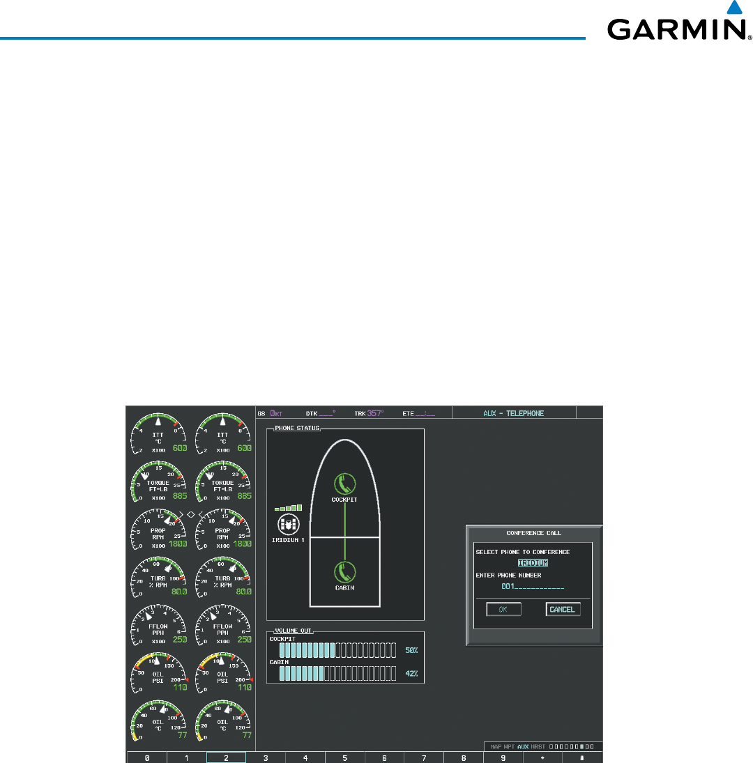
Garmin G1000 Pilot’s Guide for the Beechcraft 200/B200 Series
190-00928-04 Rev. A622
ADDITIONAL FEATURES
MAKING A CONFERENCE CALL FROM THE COCKPIT
The cabin or an external phone (two external phones if two Iridium Transceivers are installed) can be added
to a call already in progress.
Adding another phone to an active call:
1) Select the CONF Softkey on the MFD.
Or:
a) Press the MENU Key to display the Page Menu.
b) Turn either FMS Knob to place the cursor on ‘Conference Current Call’.
c) Press the ENT Key.
A window similar to that shown in Figure 8-93 will be displayed. In this example, an external phone will
be added to an active call to the cabin. Therefore, the window shows the ‘IRIDIUM’ option. If the active call
is with an external phone, ‘CABIN’ would be the option.
Figure 8-93 Initiate a Conference Call
2) Press the ENT Key. The cursor now highlights the phone number entry field.
3) Enter the phone number to be added to the call, as discussed earlier for making an external call on the Iridium
satellite network.
4) Press the ENT Key. ‘OK’ is now highlighted.
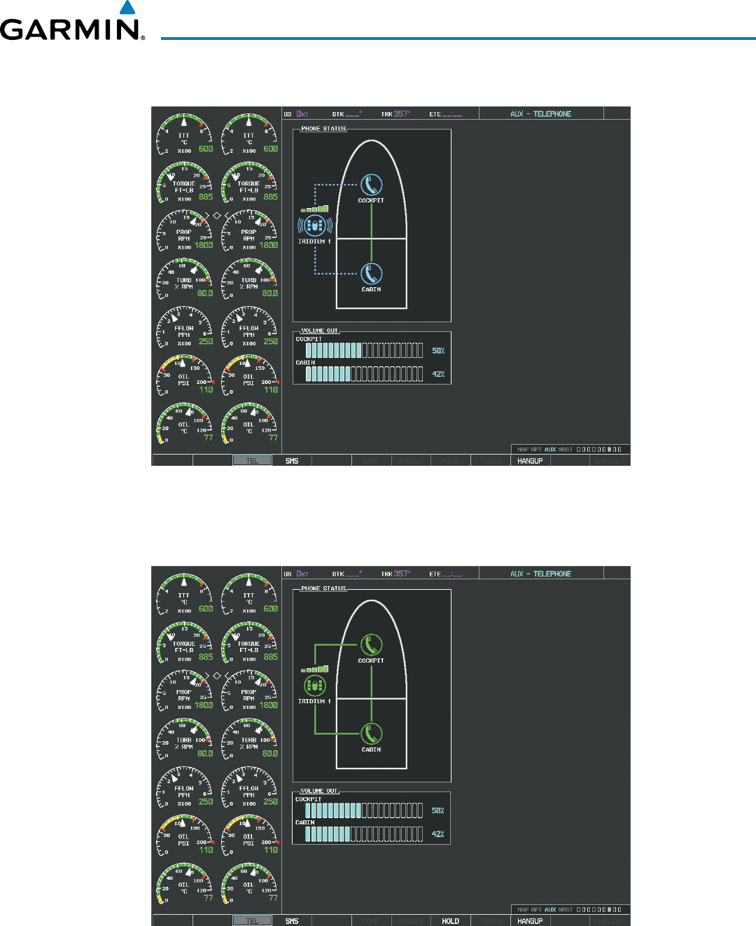
Garmin G1000 Pilot’s Guide for the Beechcraft 200/B200 Series
190-00928-04 Rev. A 623
ADDITIONAL FEATURES
5) Press the ENT Key again to place the call as shown in Figure 8‑94.
Figure 8-94 Conference in External Phone
When the external phone is answered, the call connection is indicated as in Figure 8-95.
Figure 8-95 External Phone Added
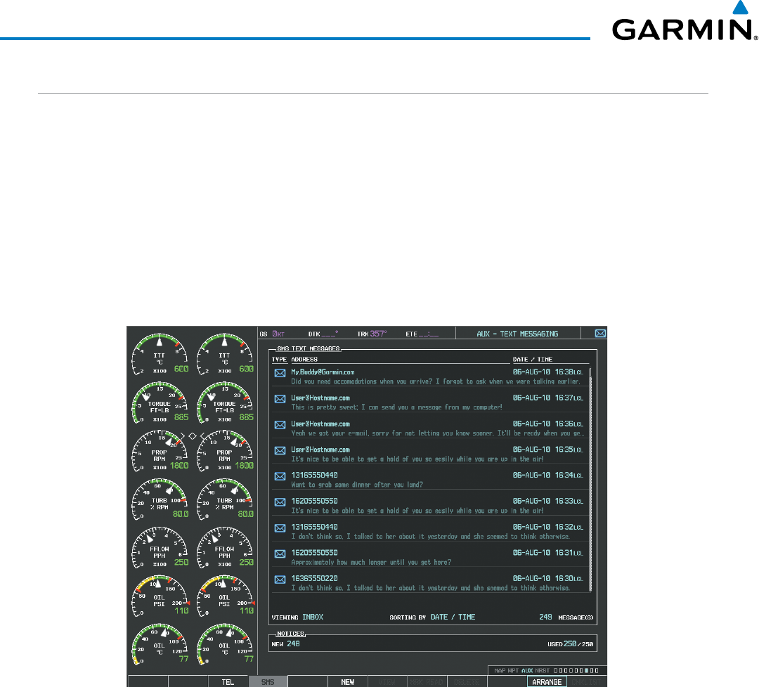
Garmin G1000 Pilot’s Guide for the Beechcraft 200/B200 Series
190-00928-04 Rev. A624
ADDITIONAL FEATURES
TEXT MESSAGING (SMS)
The pilot or copilot can send and receive text messages on the Iridium satellite network. Messages may be
sent to an email address or text message capable cellular telephone. Message length is limited to 160 characters,
including the email address.
The text messaging user interface is mainly through the AUX-TEXT MESSAGING Page.
Viewing the Text Messaging Page:
1) Turn the large FMS Knob on the MFD to select the AUX page group.
2) Turn the small FMS Knob to select the AUX ‑ TELEPHONE or AUX ‑ TEXT MESSAGING Page.
3) If necessary, select the SMS Softkey to display the AUX‑TEXT MESSAGING Page as shown in Figure 8‑96.
Figure 8-96 Text Messaging Page
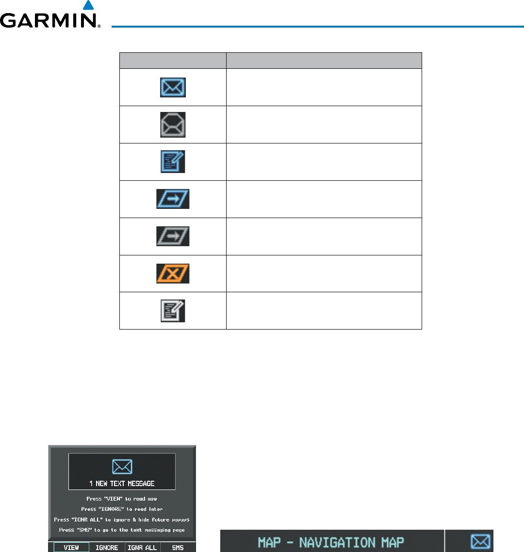
Garmin G1000 Pilot’s Guide for the Beechcraft 200/B200 Series
190-00928-04 Rev. A 625
ADDITIONAL FEATURES
Message Symbol Description
Received text message that has not been opened
Received text message that has been opened
Saved text message, draft not sent
System is sending text message
Text message has been sent
System failed to send text message
Predefined text message
Table 8-6 Text Message Symbols
VIEWING A TEXT MESSAGE WHEN RECEIVED
When viewing MFD pages other than the AUX-TEXT MESSAGING Page, a pop-up alert similar to Figure
8-97 will be displayed when a new text message is received.
Figure 8-97 New Text Message Received
New Text Message Pop-up New Text Message Symbol on MFD Page
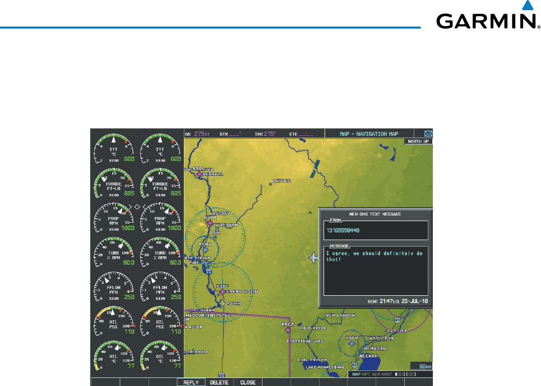
Garmin G1000 Pilot’s Guide for the Beechcraft 200/B200 Series
190-00928-04 Rev. A626
ADDITIONAL FEATURES
Select the VIEW Softkey to view the message (Figure 8-98). Selecting the IGNORE Softkey will extinguish
the pop-up window and leave the text message unopened. Selecting the IGNR ALL Softkey will extinguish
the pop-window and ignore all future incoming text messages. Selecting the SMS Softkey will display the
AUX-TEXT MESSAGING Page.
Figure 8-98 Text Message Displayed from Pop-Up Alert
The pop-up alerts may be enabled or disabled through the Page Menu.
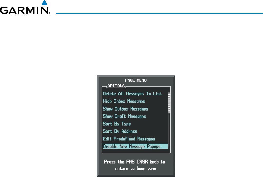
Garmin G1000 Pilot’s Guide for the Beechcraft 200/B200 Series
190-00928-04 Rev. A 627
ADDITIONAL FEATURES
Enabling/disabling incoming text message pop-up alerts:
1) With the AUX‑TEXT MESSAGING Page displayed, press the MENU Key on the MFD to display the Page Menu.
2) Turn either FMS Knob to place the cursor on ‘Disable New Message Popups’ or ‘Enable New Message
Popups’.
3) Press the ENT Key. The pop‑up alert will not be displayed when an incoming text message is received.
Figure 8-99 Disabling New Text Message Pop-Ups
REPLY TO A TEXT MESSAGE
After reading a text message, a reply may be sent.
Replying to a text message:
While viewing the text message, select the REPLY Softkey.
Or:
1) Press the MENU Key to display the Page Menu.
2) Turn either FMS Knob to place the cursor on ‘Reply To Message’.
3) Press the ENT Key.
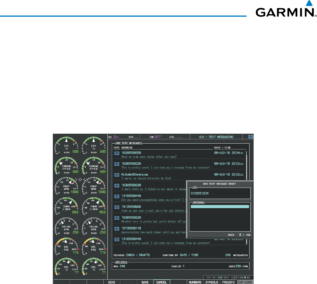
Garmin G1000 Pilot’s Guide for the Beechcraft 200/B200 Series
190-00928-04 Rev. A628
ADDITIONAL FEATURES
SENDING A TEXT MESSAGE
Text messages may be sent from the AUX-TEXT MESSAGING Page.
Sending a new text message:
1) While viewing the AUX‑TEXT MESSAGING Page, select the NEW Softkey.
Or:
a) Press the MENU Key to display the Page Menu.
b) Turn either FMS Knob to place the cursor on ‘Draft New Message’.
c) Press the ENT Key.
Figure 8-100 Composing a New Text Message
2) The TEXT MESSAGE DRAFT Window is now displayed with the cursor in the ‘TO’ field. Enter the desired
telephone number or email address. Entry can be accomplished through the alphanumeric keys on the MFD
Controller, or combination of the FMS Knob on the controller and softkeys on the MFD. The FMS Knob is used
to enter letters and numbers, or numbers can be entered from the MFD by selecting the NUMBERS Softkey.
Select the CAP LOCK Softkey to create upper and lower case alpha characters. Special characters can be
accessed by selecting the SYMBOLS Softkey. See Figure 8‑100.
3) Press the ENT Key. The cursor is now displayed in the ‘MESSAGE’ field.
4) Enter the desired message using any combination of entry methods as described in step 2.
5) Press the ENT Key.
6) Select the SEND Softkey to send the message immediately, or select the SAVE Softkey to save the message in
Outbox for sending at a later time. Select the CANCEL Softkey to delete the message.
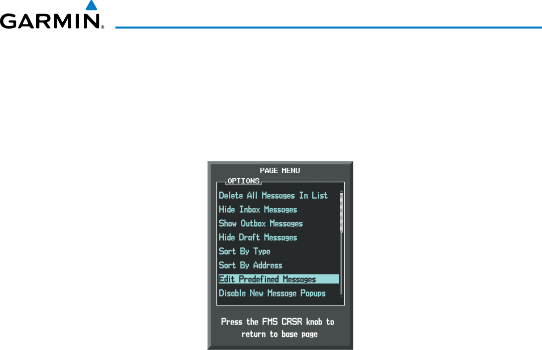
Garmin G1000 Pilot’s Guide for the Beechcraft 200/B200 Series
190-00928-04 Rev. A 629
ADDITIONAL FEATURES
PREDEFINED TEXT MESSAGES
Time and effort can be saved in typing text messages that are used repeatedly by saving these messages as
a predefined message.
Creating a predefined text message:
1) While viewing the AUX‑TEXT MESSAGING Page, press the MENU Key to display the Page Menu.
Figure 8-101 Creating/Editing Predefined Messages
2) Turn either FMS Knob to select ‘Edit Predefined Messages’ as shown in Figure 8‑101.
3) Press the ENT Key. The PREDEFINED MESSAGES view is now displayed.
4) Select the NEW Softkey.
Or:
a) Press the MENU Key to display the Page Menu.
b) Turn either FMS Knob to place the cursor on ‘Draft New Predefined Message’.
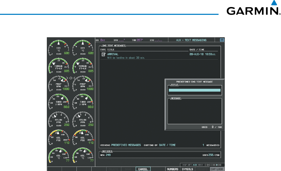
Garmin G1000 Pilot’s Guide for the Beechcraft 200/B200 Series
190-00928-04 Rev. A630
ADDITIONAL FEATURES
c) Press the ENT Key. The PREDEFINED SMS TEXT MESSAGE Window is now displayed as shown in Figure 8‑102.
Figure 8-102 Composing a Predefined Message
5) The cursor is displayed in the ‘TITLE’ field. Enter the desired message title. Entry can be accomplished through
the alphanumeric keys on the MFD Controller, or combination of the FMS Knob on the controller and softkeys
on the MFD. The FMS Knob is used to enter letters and numbers, or numbers can be entered from the MFD
by selecting the NUMBERS Softkey. Select the CAP LOCK Softkey to create upper and lower case alpha
characters. Special characters can be accessed by selecting the SYMBOLS Softkey.
6) Press the ENT Key. The cursor is now displayed in the ‘MESSAGE’ field.
7) Enter the desired message using any combination of entry methods as described in step 5.
8) Press the ENT Key.
9) Select the SAVE Softkey. The new predefined message is now shown in the displayed list. Selecting the
CANCEL Softkey will delete the message without saving.
10) Press the MENU Key to display the Page Menu.
11) Turn either FMS Knob to place the cursor on ‘Stop Editing Predefined Message’.
12) Press the ENT Key.
Sending a predefined text message:
1) While viewing the AUX‑TEXT MESSAGING Page, select the NEW Softkey.
2) The TEXT MESSAGE DRAFT Window is now displayed with the cursor in the ‘TO’ field. Enter the desired
telephone number or email address. Entry can be accomplished through the alphanumeric keys on the MFD
Controller, or combination of the FMS Knob on the controller and softkeys on the MFD. The FMS Knob is used
to enter letters and numbers, or numbers can be entered from the MFD by selecting the NUMBERS Softkey.
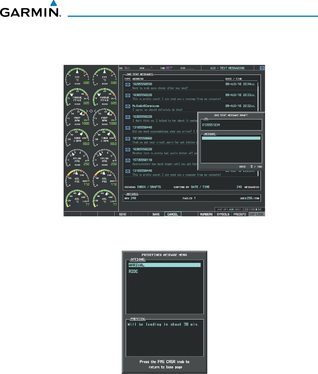
Garmin G1000 Pilot’s Guide for the Beechcraft 200/B200 Series
190-00928-04 Rev. A 631
ADDITIONAL FEATURES
Select the CAP LOCK Softkey to create upper and lower case alpha characters. Special characters can be
accessed by selecting the SYMBOLS Softkey. See Figure 8‑103.
3) Press the ENT Key. The cursor is now displayed in the ‘MESSAGE’ field (Figure 8‑103).
Figure 8-103 Predefined Message Softkey Shown When Composing a Message
4) Select the PREDEFD Softkey. The PREDEFINED MESSAGE MENU Window is displayed as seen in Figure 8‑104.
Figure 8-104 Predefined Message List
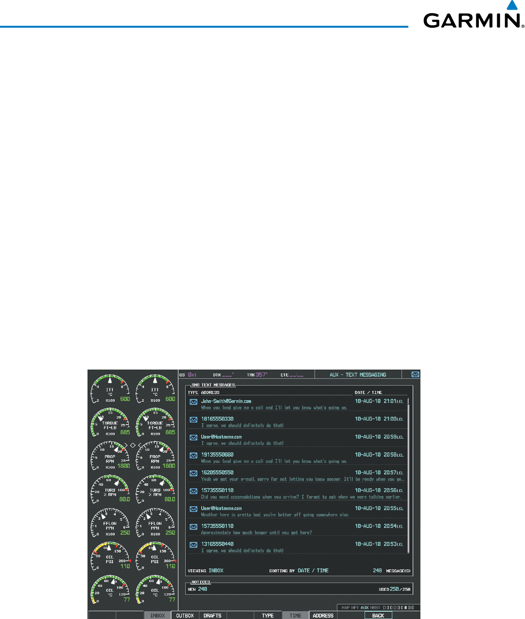
Garmin G1000 Pilot’s Guide for the Beechcraft 200/B200 Series
190-00928-04 Rev. A632
ADDITIONAL FEATURES
5) Turn either FMS Knob to select the desired predefined message.
6) Press the ENT Key. The predefined message text is inserted into the message field. If desired, the message can
be edited by using the FMS Knobs.
7) Press the ENT Key.
8) Select the SEND Softkey to transmit the message.
TEXT MESSAGE BOXES
Received text messages reside in the Inbox as ‘Read’ or ‘Unread’ messages. The Outbox contains ‘Sent” and
‘Unsent’ text messages. Saved messages that are meant to be sent later are stored as Drafts. Each text message
box may be viewed separately, or together in any combination.
Show Inbox messages:
While viewing the AUX‑TEXT MESSAGING Page, select the ARRANGE Softkey, then select the INBOX Softkey
(Figure 8‑105).
Or:
1) Press the MENU Key to display the Page Menu.
2) Turn either FMS Knob to place the cursor on ‘Show Inbox Messages’.
3) Press the ENT Key. The message box selected for viewing is indicated at the bottom left of the list window.
Figure 8-105 Text Message Inbox

Garmin G1000 Pilot’s Guide for the Beechcraft 200/B200 Series
190-00928-04 Rev. A 633
ADDITIONAL FEATURES
Show Outbox messages:
While viewing the AUX‑TEXT MESSAGING Page, select the ARRANGE Softkey, then select the OUTBOX
Softkey.
Or:
1) Press the MENU Key to display the Page Menu.
2) Turn either FMS Knob to place the cursor on ‘Show Outbox Messages’.
3) Press the ENT Key. The message box selected for viewing is indicated at the bottom left of the list window.
Show Draft messages:
While viewing the AUX‑TEXT MESSAGING Page, select the ARRANGE Softkey, then select the DRAFTS
Softkey.
Or:
1) Press the MENU Key to display the Page Menu.
2) Turn either FMS Knob to place the cursor on ‘Show Draft Messages’.
3) Press the ENT Key. The message box selected for viewing is indicated at the bottom left of the list window.
MANAGING TEXT MESSAGES
The viewed messages may be listed according to the date/time the message was sent or received, the type of
message (read, unread, sent, unsent, etc.), or by message address.
Viewing messages sorted by message date/time:
While viewing the AUX‑TEXT MESSAGING Page, select the ARRANGE Softkey, then select the TIME Softkey
(Figure 8‑105).
Or:
1) Press the MENU Key to display the Page Menu.
2) Turn either FMS Knob to place the cursor on ‘Sort By Date/Time’.
3) Press the ENT Key. The sorting selection is indicated at the bottom center of the list window (Figure 8‑106).
Viewing messages sorted by message type:
While viewing the AUX‑TEXT MESSAGING Page, select the ARRANGE Softkey, then select the TYPE Softkey.
Or:
1) Press the MENU Key to display the Page Menu.
2) Turn either FMS Knob to place the cursor on ‘Sort By Type’.
3) Press the ENT Key. The sorting selection is indicated at the bottom center of the list window.
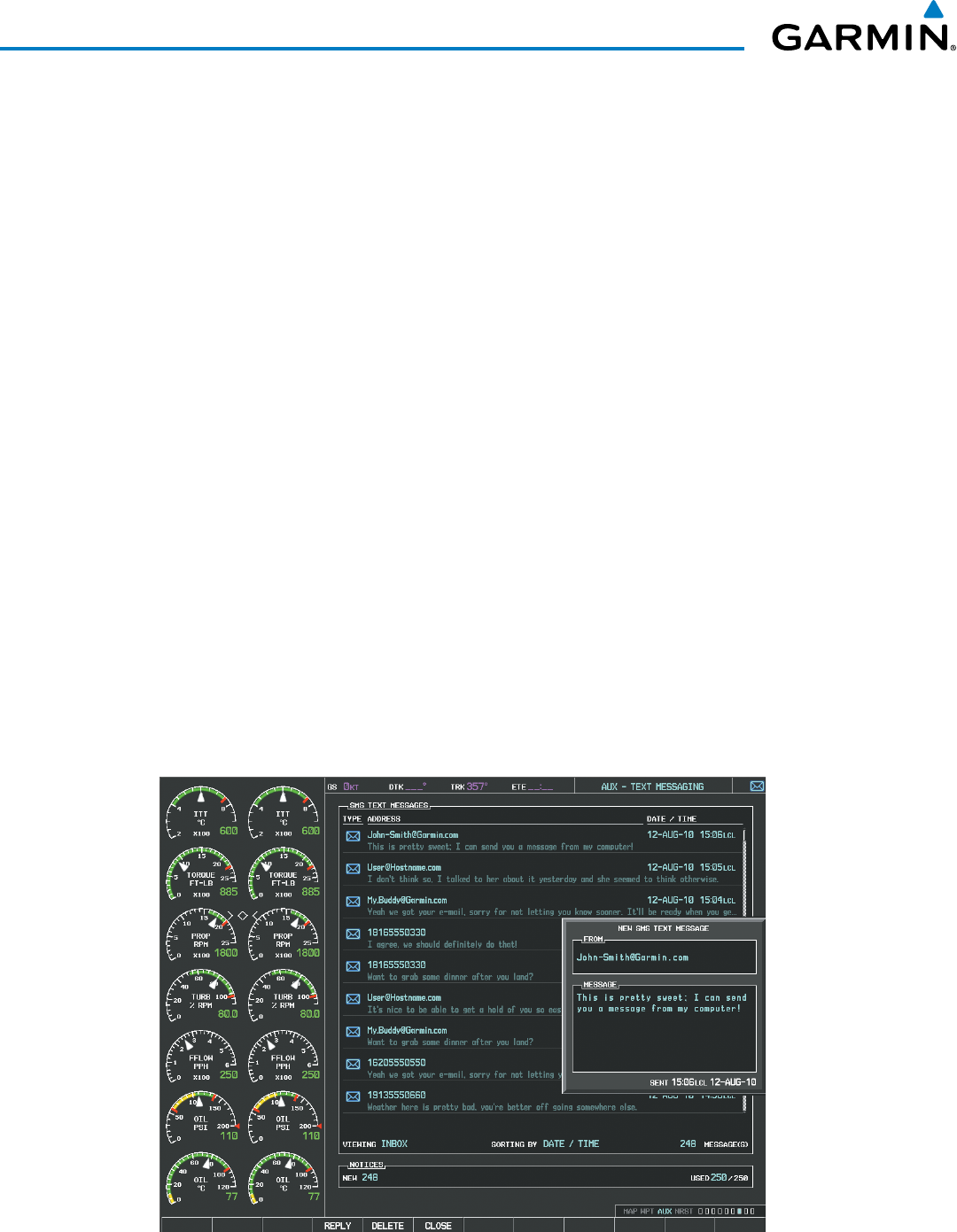
Garmin G1000 Pilot’s Guide for the Beechcraft 200/B200 Series
190-00928-04 Rev. A634
ADDITIONAL FEATURES
Viewing messages sorted by address:
While viewing the AUX‑TEXT MESSAGING Page, select the ARRANGE Softkey, then select the ADDRESS
Softkey.
Or:
1) Press the MENU Key to display the Page Menu.
2) Turn either FMS Knob to place the cursor on ‘Sort By Address’.
3) Press the ENT Key. The sorting selection is indicated at the bottom center of the list window.
Viewing the content of a text message:
1) While viewing the AUX‑TEXT MESSAGING Page, select the desired message box.
2) Press the FMS Knob to activate the cursor.
3) Turn either FMS Knob to select the desired message.
4) Select the VIEW Softkey.
Or:
Press the ENT Key.
Or:
a) Press the MENU Key to display the Page Menu.
b) Turn either FMS Knob to place the cursor on ‘View Selected Message’.
c) Press the ENT Key.
Message content is displayed as shown in Figure 8‑106).
Figure 8-106 Veiwing Message Content

Garmin G1000 Pilot’s Guide for the Beechcraft 200/B200 Series
190-00928-04 Rev. A 635
ADDITIONAL FEATURES
5) To close the text message, select the CLOSE Softkey.
Or:
a) Press the MENU Key to display the Page Menu.
b) Turn either FMS Knob to place the cursor on ‘Close Message’.
c) Press the ENT Key.
Marking selected message as read:
1) While viewing the Inbox on the AUX‑TEXT MESSAGING Page, press the FMS Knob to activate the cursor.
2) Turn either FMS Knob to select the desired message.
3) Select the MRK READ Softkey.
Or:
a) Press the MENU Key to display the Page Menu.
b) Turn either FMS Knob to place the cursor on ‘Mark Selected Message As Read’.
c) Press the ENT Key.
The message symbol now indicates the message has been opened.
Marking all messages as read:
1) While viewing the Inbox on the AUX‑TEXT MESSAGING Page, press the MENU Key to display the Page Menu.
2) Turn either FMS Knob to place the cursor on ‘Mark All New Messages As Read’.
3) Press the ENT Key. A confirmation window is displayed.
4) With cursor highlighting ‘YES’, press the ENT Key. The message symbols now indicate all the message have
been opened.
Delete a message:
1) While viewing the Inbox on the AUX‑TEXT MESSAGING Page, press the FMS Knob to activate the cursor.
2) Turn either FMS Knob to select the desired message.
3) Select the DELETE Softkey.
Or:
a) Press the MENU Key to display the Page Menu.
b) Turn either FMS Knob to place the cursor on ‘Delete Selected Message’.
c) Press the ENT Key.
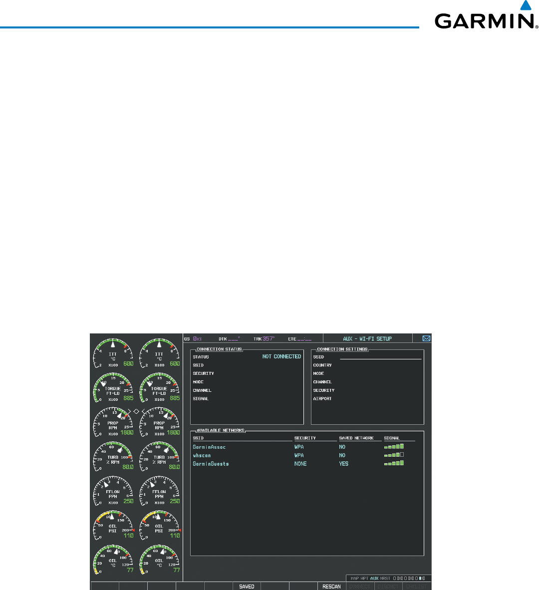
Garmin G1000 Pilot’s Guide for the Beechcraft 200/B200 Series
190-00928-04 Rev. A636
ADDITIONAL FEATURES
8.7 WI-FI CONNECTIONS
The optional GDL 59 Data Link provides a high speed IEEE 802.11g Wi-Fi data link between the aircraft and a
ground computer network while the aircraft is on the ground and located within range of the network.
The system is capable of WEP64, WEP128,WPA-PSK, and WPA2-PSK encryption formats. WPA-Enterprise
and WPA2-Enterprise are not supported. Connections that require web proxies, captive portals, or other elements
that require user credentials, including a username and password or a redemption or access code; or require
action such as accepting a user agreement, are not supported.
Control and monitoring of Wi-Fi functions are accomplished through the AUX-WI-FI SETUP Page.
Viewing the Wi-Fi Setup Page:
1) Turn the large FMS Knob on the MFD to select the AUX page group.
2) Turn the small FMS Knob to select the AUX ‑ WI‑FI SETUP Page.
Setting up a new Wi-Fi connection:
1) Select the AVAIL Softkey on the MFD. A list of available networks will be displayed in the AVAILABLE NETWORKS
window as shown in Figure 8‑107. Signal strength is shown for each network, as well as security requirements
and whether the network has been saved in the system’s memory.
Figure 8-107 Available Wi-Fi Networks
2) If necessary, select the RESCAN Softkey to have the system scan again for available networks.
Or:
a) Press the MENU Key to display the Page Menu.
b) Turn either FMS Knob to place the cursor on ‘Rescan Available Networks’.
c) Press the ENT Key.
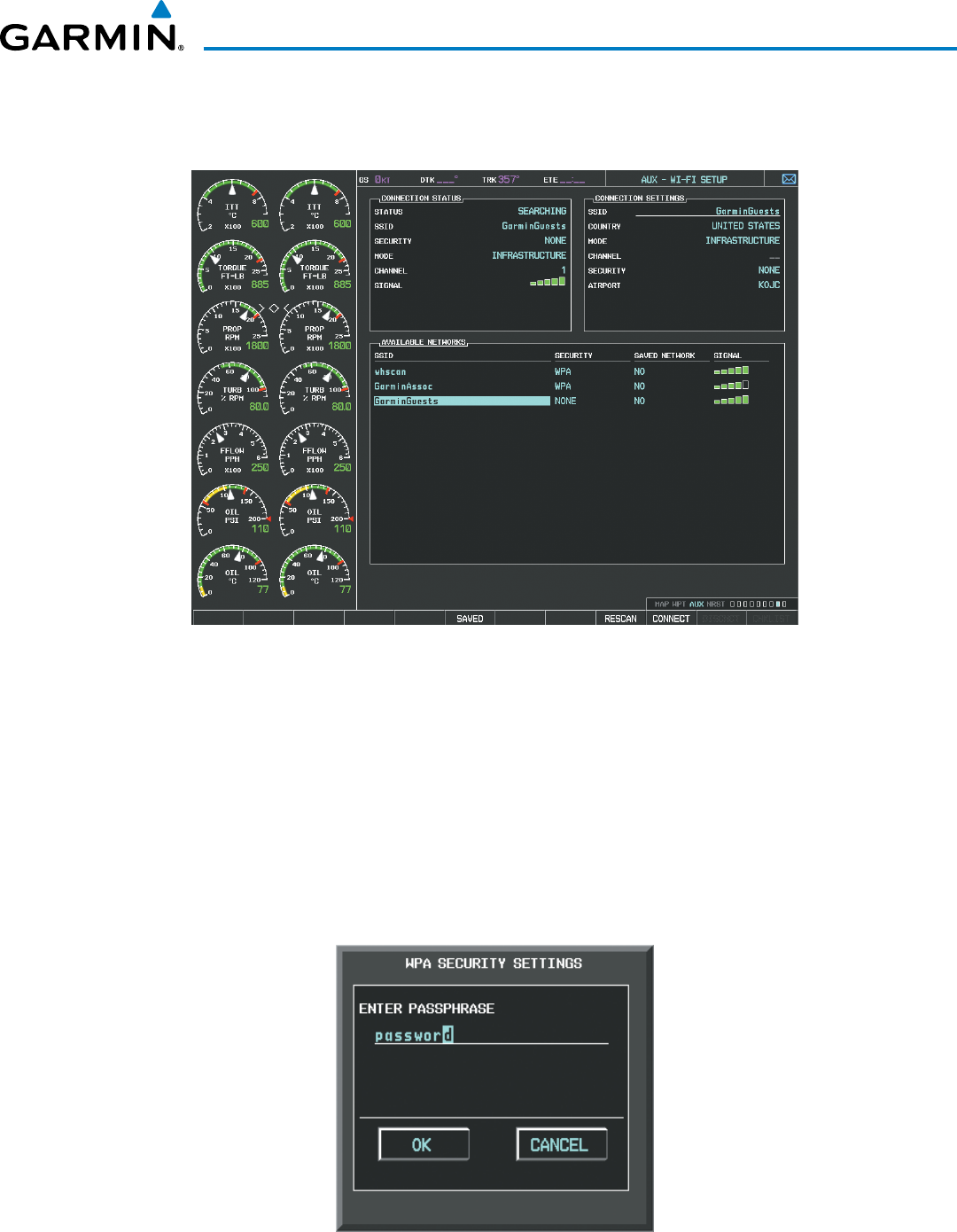
Garmin G1000 Pilot’s Guide for the Beechcraft 200/B200 Series
190-00928-04 Rev. A 637
ADDITIONAL FEATURES
3) Press the FMS Knob to place the cursor in the list of networks.
4) Turn either FMS Knob to select the desired network. See Figure 8‑108.
Figure 8-108 Desired Network Selected
5) Select the CONNECT Softkey.
Or:
a) Press the MENU Key to display the Page Menu.
b) Turn either FMS Knob to place the cursor on ‘Connect To Selected Network’.
c) Press the ENT Key.
6) If the network is secured, a window similar to Figure 8‑109 will be displayed in order to enter the necessary
passcode. Use the FMS Knobs to enter the desired alpha numeric characters. Select the CAP LOCK Softkey to
enter upper case letters. If there is no security associated with the network, proceed to step 9.
Figure 8-109 Enter Security Code
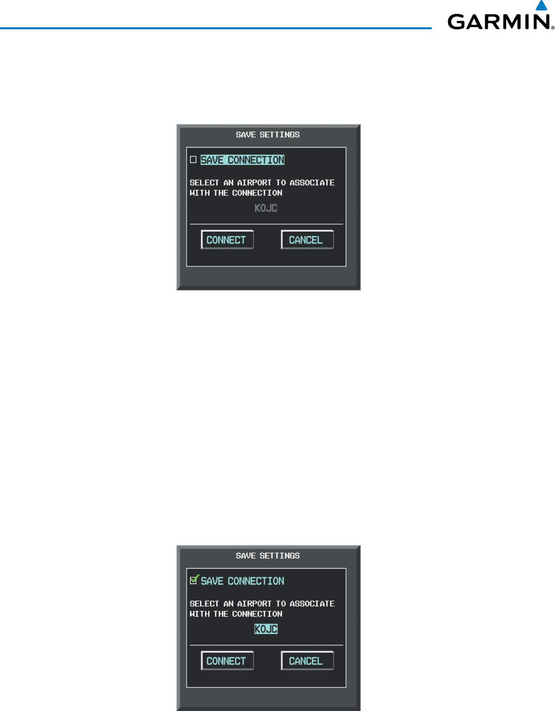
Garmin G1000 Pilot’s Guide for the Beechcraft 200/B200 Series
190-00928-04 Rev. A638
ADDITIONAL FEATURES
7) Press the ENT Key. ‘OK’ will be highlighted.
8) Press the ENT Key again.
9) The SAVE SETTINGS window is now displayed with the cursor highlighting ‘SAVE CONNECTION’.
Figure 8-110 Save Option
10) The selected network can be saved to system memory to make re‑connection easier at a later time.
Connecting the selected network without saving:
a) Turn the large FMS Knob to move the cursor to highlight ‘CONNECT’.
b) Press the ENT Key.
Saving and connect the selected network:
a) Press the ENT Key. A checkmark is placed in the checkbox and the cursor moves to the airport field as shown
in Figure 8‑111.
b) Using the FMS Knobs, enter an airport identifier to be associated with the saved network. This aids in identifying
the network later in the event of duplicate network names.
c) Press the ENT Key. The cursor moves to ‘CONNECT’.
d) Press the ENT Key again to connect to the selected network.
Figure 8-111 Save Connection
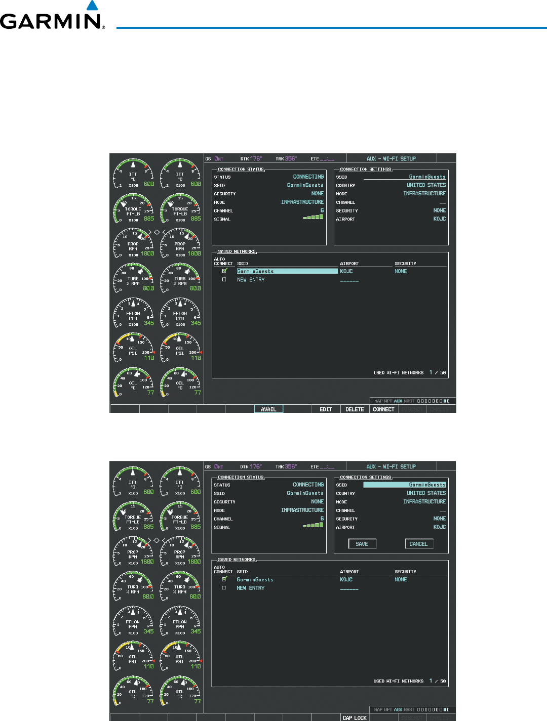
Garmin G1000 Pilot’s Guide for the Beechcraft 200/B200 Series
190-00928-04 Rev. A 639
ADDITIONAL FEATURES
Editing a saved network:
1) While viewing list of saved networks, press the FMS Knob to activate the cursor as seen in Figure 8‑112.
2) Turn either FMS Knob to highlight the network to be edited.
3) Pressing the ENT Key at this point will check or uncheck the AUTO CONNECT checkbox. When a checkmark is
present, the system will automatically connect to the network when within range.
Figure 8-112 Select Network to be Edited
4) Select the EDIT Softkey. The cursor now appears in the CONNECTION SETTINGS window as shown in Figure 8‑113.
Figure 8-113 Select Attributes to Edit

Garmin G1000 Pilot’s Guide for the Beechcraft 200/B200 Series
190-00928-04 Rev. A640
ADDITIONAL FEATURES
5) Turn the large FMS Knob to select the network attribute to be edited.
6) Turn the small FMS Knob to begin editing the field.
7) When the entry is complete, press the ENT Key.
8) Turn the large FMS Knob or press the ENT Key until ‘SAVE’ is highlighted.
9) Press the ENT Key.
Disconnecting a Wi-Fi network:
Select the DISCNCT Softkey.
Or:
1) Press the MENU Key to display the Page Menu.
2) Turn either FMS Knob to place the cursor on ‘Disconnect From Network’.
3) Press the ENT Key.
Deleting a saved Wi-Fi network:
1) While viewing the list of saved networks, press the FMS Knob to activate the cursor.
2) Turn either FMS Knob to highlight the network to be deleted.
3) Select the DELETE Softkey. The selected network is removed from the list.
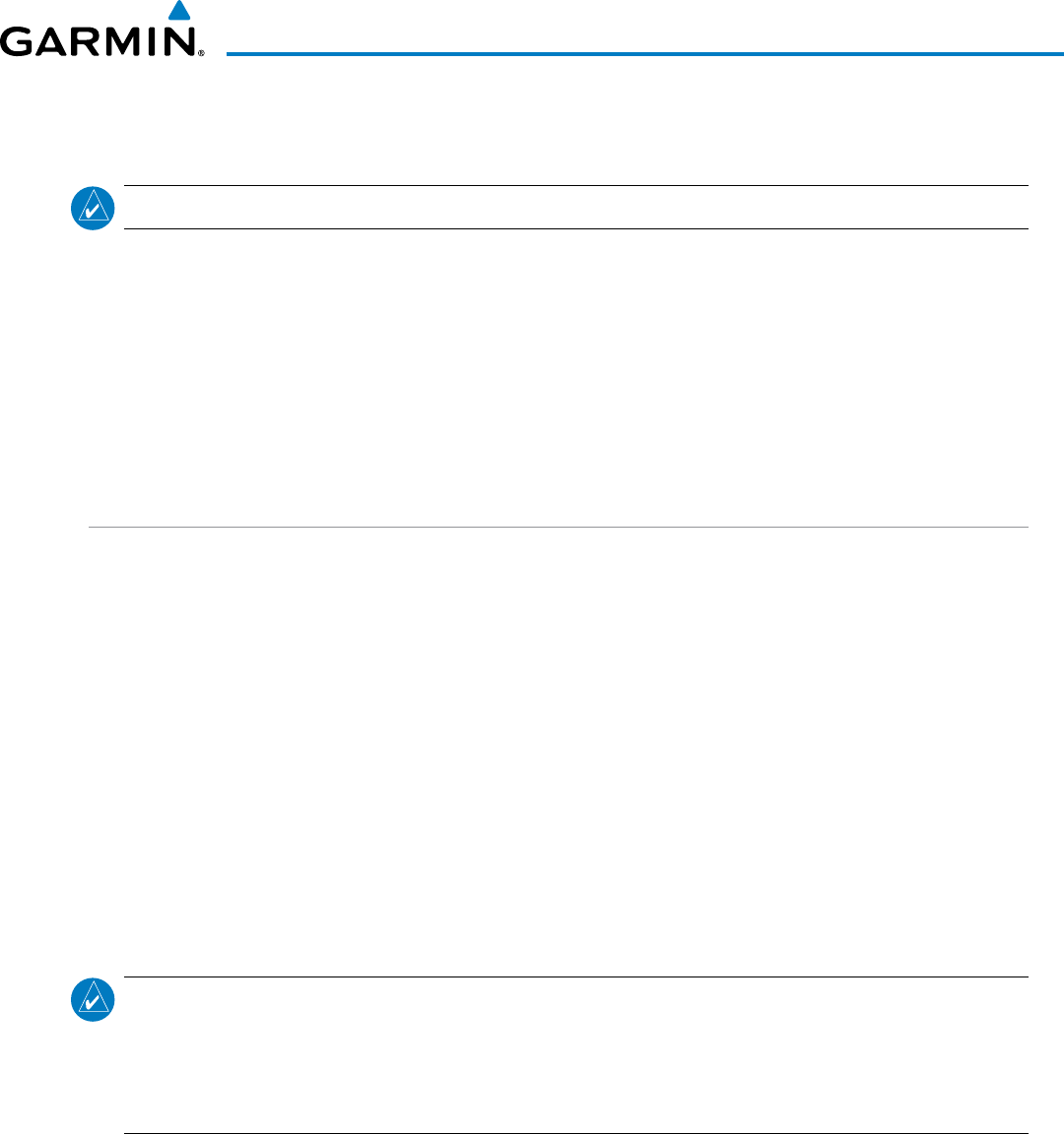
Garmin G1000 Pilot’s Guide for the Beechcraft 200/B200 Series
190-00928-04 Rev. A 641
ADDITIONAL FEATURES
8.8 SIRIUSXM RADIO ENTERTAINMENT
NOTE: Refer to the Hazard Avoidance Section for information about SiriusXM Weather products.
The optional SiriusXM Satellite Radio entertainment feature of the GDL 69A Data Link Receiver is available for
the pilot’s and passengers’ enjoyment. The GDL 69A can receive SiriusXM Satellite Radio entertainment services
at any altitude throughout the Continental U.S. Entertainment audio is available only on the GDL 69A Data Link
Receiver, not the GDL 69.
SiriusXM Satellite Radio offers a variety of radio programming over long distances without having to constantly
search for new stations. Based on signals from satellites, coverage far exceeds land-based transmissions.
SiriusXM Satellite Radio services are subscription-based. For more information on specific service packages, visit
www.siriusxm.com.
ACTIVATING SIRIUSXM SATELLITE RADIO SERVICES
The service is activated by providing SiriusXM Satellite Radio with either one or two coded IDs, depending on
the equipment. Either the Audio Radio ID or the Data Radio ID, or both, must be provided to SiriusXM Satellite
Radio to activate the entertainment subscription.
It is not required to activate both the entertainment and weather service subscriptions with the GDL 69A.
Either or both services can be activated. SiriusXM Satellite Radio uses one or both of the coded IDs to send an
activation signal that, when received by the GDL 69A, allows it to play entertainment programming.
These IDs are located:
• On the label on the back of the Data Link Receiver
• On the XM Information Page on the MFD (Figure 8-116)
• On the XM Satellite Radio Activation Instructions included with the unit (available at www.garmin.com, P/N
190-00355-04)
Contact the installer if the Data Radio ID and the Audio Radio ID cannot be located.
NOTE
: The LOCK Softkey on the XM Information Page (Auxiliary Page Group) is used to save GDL 69A
activation data when the SiriusXM services are initially set up. It is not used during normal SiriusXM
Satellite Radio operation, but there should be no adverse effects if inadvertently selected during flight.
Refer to the GDL 69/69A XM Satellite Radio Activation Instructions (190-00355-04, Rev H or later) for
further information.
Activating the SiriusXM Satellite Radio services:
1) Contact SiriusXM Satellite Radio. Follow the instructions provided by SiriusXM Satellite Radio services.
2) Select the Auxiliary Page Group.
3) Select the next to last page in the AUX Page Group.
4) Select the INFO Softkey to display the XM Information Page.
5) Verify that the desired services are activated.
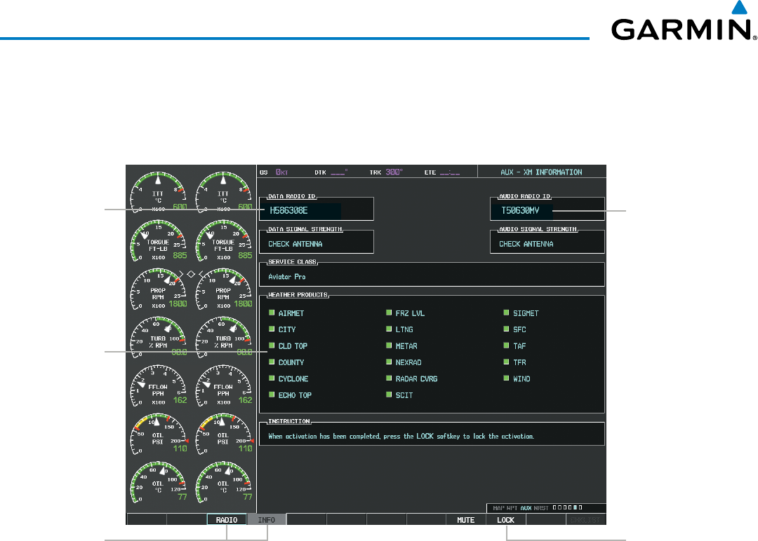
Garmin G1000 Pilot’s Guide for the Beechcraft 200/B200 Series
190-00928-04 Rev. A642
ADDITIONAL FEATURES
6) Select the LOCK Softkey.
7) Turn the large FMS Knob to highlight YES.
8) To complete activation, press the ENT Key.
RADIO
and
INFO
Softkeys
Figure 8-114 XM Information Page
Audio
Radio ID
Weather
Products
Window
Data
Radio ID
LOCK
Softkey
is Used to Save
Activation Data
During Initial
Setup
If SiriusXM Weather services have not been activated, all the weather product boxes are blank on the XM
Information Page and a yellow Activation Required message is displayed in the center of the Weather Data
Link Page (Map Page Group). The Service Class refers to the groupings of weather products available for
subscription.
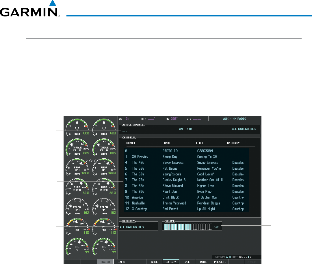
Garmin G1000 Pilot’s Guide for the Beechcraft 200/B200 Series
190-00928-04 Rev. A 643
ADDITIONAL FEATURES
USING SIRIUSXM RADIO
The XM Radio Page provides information and control of the audio entertainment features of the SiriusXM
Satellite Radio.
Selecting the XM Radio Page:
1) Turn the large
FMS
Knob to select the Auxiliary Page Group.
2) Turn the small
FMS
Knob to select the displayed AUX ‑ XM Information Page.
3) Select the
RADIO
Softkey to show the XM Radio Page where audio entertainment is controlled.
Volume
Field
Figure 8-115 XM Radio Page
Categories
Field
Channel
List
Active
Channels
ACTIVE CHANNEL AND CHANNEL LIST
The Active Channel Box on the XM Radio Page displays the currently selected channel that the SiriusXM
Radio is using.
The Channels List Box of the XM Radio Page shows a list of the available channels for the selected category.
Channels can be stepped through one at a time or may be selected directly by channel number.
Selecting a channel from the channel list:
1) While on the XM Radio Page, select the CHNL Softkey.
2) Select the CH + Softkey to go up through the list in the Channel Box, or move down the list with the CH – Softkey.
Or:

Garmin G1000 Pilot’s Guide for the Beechcraft 200/B200 Series
190-00928-04 Rev. A644
ADDITIONAL FEATURES
1) Press the
FMS
Knob to highlight the channel list and turn the large
FMS
Knob to scroll through the channels.
2) Press the ENT Key to activate the selected channel.
Selecting a channel directly:
1) While on the XM Radio Page, select the CHNL Softkey.
2) Select the DIR CH Softkey. The channel number in the Active Channel Box is highlighted.
3) Select the numbered softkeys located on the bottom of the display to directly select the desired channel
number.
4) Press the ENT Key to activate the selected channel.
CATEGORY
The Category Box of the XM Radio Page displays the currently selected category of audio. Categories of
channels such as jazz, rock, or news can be selected to list the available channels for a type of music or other
contents. One of the optional categories is PRESETS to view channels that have been programmed.
Selecting a category:
1) Select the CATGRY Softkey on the XM Radio Page.
2) Select the CAT + and CAT - Softkeys to cycle through the categories.
Or:
Turn the small
FMS
Knob to display the Categories list. Highlight the desired category with the small
FMS
Knob
and press the
ENT
Key. Selecting All Categories places all channels in the list.
Figure 8-116 Categories List
PRESETS
Up to 15 channels from any category can be assigned a preset number. The preset channels are selected by
selecting the PRESETS and MORE Softkeys. Then the preset channel can be selected directly and added to
the channel list for the Presets category.
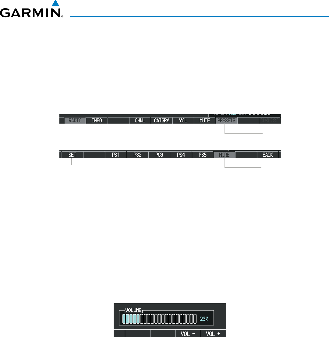
Garmin G1000 Pilot’s Guide for the Beechcraft 200/B200 Series
190-00928-04 Rev. A 645
ADDITIONAL FEATURES
Setting a preset channel number:
1) On the XM Radio Page, while listening to an Active Channel that is wanted for a preset, select the PRESETS
Softkey to access the first five preset channels (PS1 - PS5).
2) Select the MORE Softkey to access the next five channels (PS6 – PS10), and again to access the last five
channels (PS11 – PS15). Selecting the MORE Softkey repeatedly cycles through the preset channels.
3) Select any one of the (PS1 - PS15) softkeys to assign a number to the active channel.
4) Select the SET Softkey on the desired channel number to save the channel as a preset.
Figure 8-117 Accessing and Selecting SiriusXM Preset Channels
Select
PRESETS
to
Access the Preset
Channels Softkeys
Select
MORE
to Cycle
Through the Preset
Channels
Select
SET
to Save Each
Preset Channel
Selecting the BACK Softkey, or 45 seconds of softkey inactivity, returns the system to the top level softkeys.
VOLUME
Radio volume is shown as a percentage. Volume level is controlled by selecting the VOL Softkey, which
brings up the MUTE Softkey and the volume increase and decrease softkeys.
Adjusting the volume:
1) With the XM Radio Page displayed, select the VOL Softkey.
2) Select the VOL – Softkey to reduce volume or select the VOL + Softkey to increase volume. (Once the VOL
Softkey is selected, the volume can also be adjusted using the small FMS Knob.)
Figure 8-118 Volume Control
SiriusXM Radio volume may also be adjusted on each passenger headset.
Mute SiriusXM audio:
1) Select the XM Radio Page or XM Information Page.
2) Select the MUTE Softkey to mute the audio. Select the MUTE Softkey again to unmute the audio.
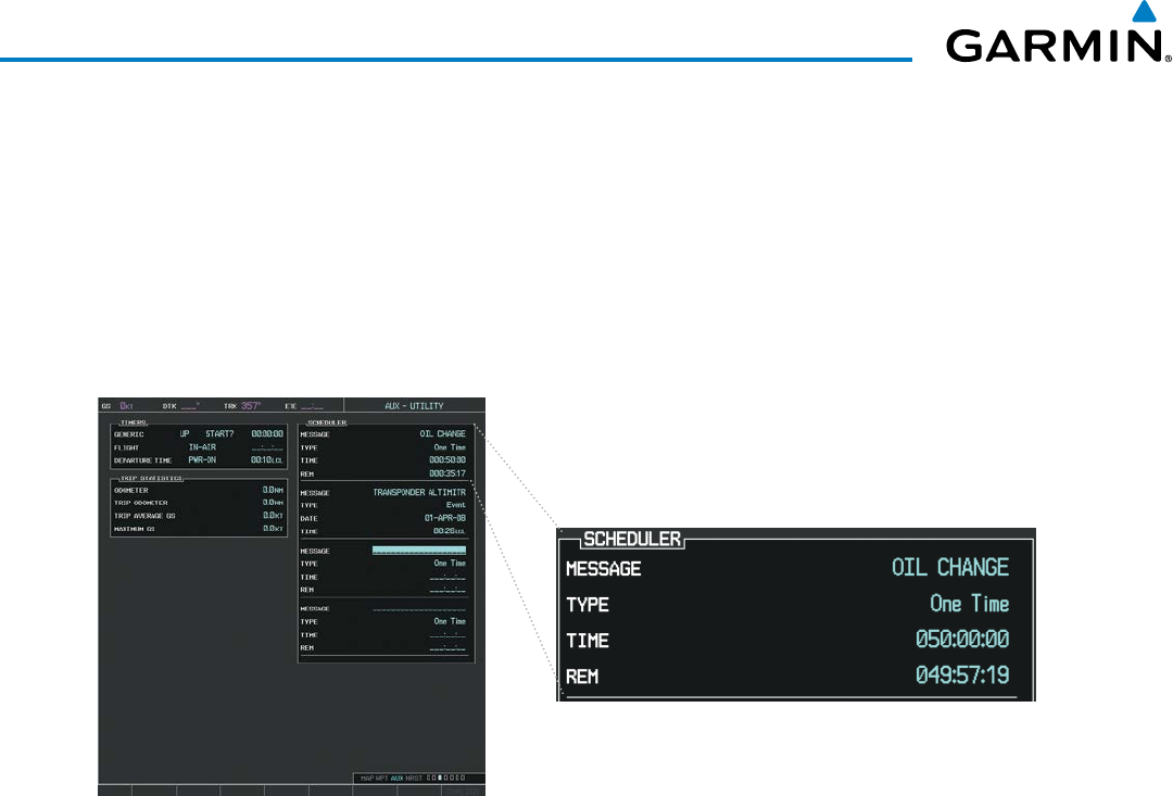
Garmin G1000 Pilot’s Guide for the Beechcraft 200/B200 Series
190-00928-04 Rev. A646
ADDITIONAL FEATURES
8.9 SCHEDULER
The Scheduler feature can be used to enter and display reminder messages (e.g., Change oil, Switch fuel tanks,
or Altimeter-Transponder Check) in the Alerts Window on the PFD. Messages can be set to display based on
a specific date and time (event), once the message timer reaches zero (one-time; default setting), or recurrently
whenever the message timer reaches zero (periodic). Message timers set to periodic alerting automatically reset
to the original timer value once the message is displayed. When power is cycled, all messages are retained until
deleted, and message timer countdown is resumed.
Figure 8-119 Scheduler (Utility Page)
Entering a scheduler message:
1) Select the AUX ‑ Utility Page.
2) Press the FMS Knob momentarily to activate the flashing cursor.
3) Turn the large FMS Knob to highlight the first empty scheduler message naming field.
4) Use the FMS Knob to enter the message text to be displayed in the Messages Window and press the
ENT
Key.
5) Press the ENT Key again or use the large FMS Knob to move the cursor to the field next to Type.
6) Turn the small FMS Knob to select the message type:
• Event—Message issued at the specified date/time
• One‑time—Message issued when the message timer reaches zero (default setting)
• Periodic—Message issued each time the message timer reaches zero
7) Press the ENT Key again or use the large FMS Knob to move the cursor to the next field.
8) For periodic and one‑time messages, use the FMS Knob to enter the timer value (HH:MM:SS) from which to
countdown and press the ENT Key.
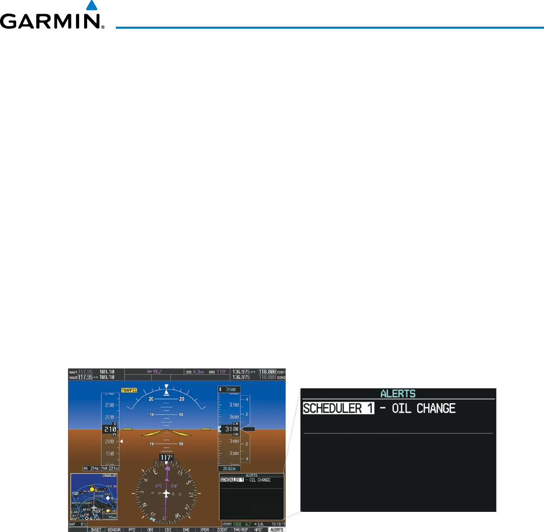
Garmin G1000 Pilot’s Guide for the Beechcraft 200/B200 Series
190-00928-04 Rev. A 647
ADDITIONAL FEATURES
9) For event‑based messages:
a) Use the FMS Knob to enter the desired date (DD‑MM‑YY) and press the ENT Key.
b) Press the ENT Key again or use the large FMS Knob to move the cursor to the next field.
c) Use the FMS Knob to enter the desired time (HH:MM) and press the ENT Key.
10) Press the ENT Key again or use the large FMS Knob to move the cursor to enter the next message.
Deleting a scheduler message:
1) Select the AUX ‑ Utility Page.
2) Press the FMS Knob momentarily to activate the flashing cursor.
3) Turn the large FMS Knob to highlight the name field of the scheduler message to be deleted.
4) Press the CLR Key to clear the message text. If the CLR Key is pressed again, the message is restored.
5) Press the ENT Key while the message line is cleared to clear the message time.
Scheduler messages appear in the Messages Window on the PFD. When a scheduler message is waiting, the
ALERTS Softkey label changes to ADVISORY. Pressing the ADVISORY Softkey opens the Messages Window
and acknowledges the scheduler message. The softkey label reverts to ALERTS when pressed. Pressing the
ALERTS Softkey again removes the Messages Window from the display, and the scheduler message is deleted
from the message queue.
Figure 8-120 PFD Messages Window

Garmin G1000 Pilot’s Guide for the Beechcraft 200/B200 Series
190-00928-04 Rev. A648
ADDITIONAL FEATURES
8.10 FLIGHT DATA LOGGING
NOTE: Some aircraft installations may not provide all aircraft/engine data capable of being logged by the
system.
The Flight Data Logging feature will automatically store critical flight and engine data on an SD data card (up
to 16GB) inserted into the top card slot of the MFD. Approximately 1,000 flight hours can be recorded for each
1GB of available space on the card.
Data is written to the SD card once each second while the MFD is powered on. All flight data logged on a
specific date is stored in a file named in a format which includes the date, time, and nearest airport identifier. The
file is created automatically each time the G1000 system is powered on, provided an SD card has been inserted.
The status of the Flight Data Logging feature can be viewed on the AUX-UTILITY Page. If no SD card has been
inserted, “NO CARD” is displayed. When data is being written to the SD card, “LOGGING DATA” is displayed.
The .csv file may be viewed with Microsoft Excel® or other spreadsheet applications.
The following is a list of data parameters the G1000 system is capable of logging for the Beechcraft 200/B200
aircraft.
• Date
• Time
• GPS altitude (MSL)
• GPS altitude (WGS84 datum)
• Baro-Corrected altitude (feet)
• Baro Correction (in/Hg)
• Indicated airspeed (kts)
• Vertical speed (fpm)
• GPS vertical speed (fpm)
• OAT (degrees C)
• True airspeed (knots)
• Pitch Attitude Angle (degrees)
• Roll Attitude Angle (degrees)
• Lateral and Vertical G Force (g)
• Ground Speed (kts)
• Ground Track (degrees
magnetic)
• Latitude (degrees; geodetic;
+North)
• Longitude (degrees; geodetic;
+East)
• Magnetic Heading (degrees)
• HSI source
• Selected course
• Com1/Com2 frequency
• Nav1/Nav2 frequency
• CDI deflection
• VDI/GP/GS deflection
• Wind Direction (degrees)
• Wind Speed (knots)
• Active Waypoint Identifier
• Distance to next waypoint (nm)
• Bearing to next waypoint
(degrees)
• Magnetic variation (degrees)
• Autopilot On/Off
• AFCS roll/pitch modes
• AFCS roll/pitch commands
• GPS fix
• GPS horizontal alert limit
• GPS vertical alert limit
• SBAS GPS horizontal protection
level
• SBAS GPS vertical protection
level
• Fuel Qty (right & left)(gals)
• Fuel Flow (gph)
• Turbine RPM
• Oil Pressure (psi)
• Oil Temperature (deg. F)
• ITT (deg. F)
• Torque

Garmin G1000 Pilot’s Guide for the Beechcraft 200/B200 Series
190-00928-04 Rev. A 649
ADDITIONAL FEATURES
The file containing the recorded data will appear in the format shown in Figure 8-121. This file can be imported
into most computer spreadsheet applications.
log_130210_104506_KIXD.csv
Local Date
YYMMDD Local 24hr Time
HHMMSS
Nearest Airport
(A blank will be
inserted if no
airport is found)
Figure 8-121 Log File Format
Data logging status can be monitored on the AUX-UTILITY Page.

Garmin G1000 Pilot’s Guide for the Beechcraft 200/B200 Series
190-00928-04 Rev. A650
ADDITIONAL FEATURES
8.11 ELECTRONIC STABILITY & PROTECTION (ESP™)
Electronic Stability and Protection (ESP™) is an optional feature that is intended to discourage the exceedance of
attitude, established airspeed and angle of attack parameters. This feature will only function when the aircraft is
above 200 feet AGL and the autopilot is not engaged.
ESP engages when the aircraft exceeds one or more conditions (pitch, roll, Vmo, Mmo, and/or angle of attack)
beyond the normal flight parameters. Enhanced stability for each condition is provided by applying a force to
the appropriate control surface to return the aircraft to the normal flight envelope. This is perceived by the pilot
as resistance to control movement in the undesired direction when the aircraft approaches a steep attitude, high
airspeed, or when a stall is imminent.
As the aircraft deviates further from the normal attitude, angle of attack, or airspeed continues to increase, the
force increases (up to an established maximum) to encourage control movement in the direction necessary to return
to the normal attitude and/or airspeed range. Except in the case of high airspeed, when maximum force is reached,
force remains constant up to the maximum engagement limit. Above the maximum engagement limit, forces are no
longer applied. There is no maximum engagement related to a high airspeed condition.
When ESP has been engaged for more than ten seconds (cumulative; not necessarily consecutive seconds) of a
20-second interval, the autopilot is automatically engaged with the flight director in Level Mode, bringing the aircraft
into level flight. An aural “Engaging Autopilot” alert is played and the flight director mode annunciation will indicate
‘LVL’ for vertical and lateral modes.
The pilot can interrupt ESP by pressing and holding either the Control Wheel Steering (CWS) or Autopilot
Disconnect (AP/YD DISC TRIM INTRPT) switch. Upon releasing the CWS or AP/YD DISC TRIM INTRPT
switch, ESP force will again be applied, provided aircraft attitude, angle of attack and/or airspeed are within their
respective engagement limits. ESP can also be overridden by overpowering the servo’s mechanical torque limit.
ESP can be enabled or disabled on the AUX-SYSTEM SETUP 2 Page on the MFD.
To enable or disable ESP:
1) Turn the large
FMS
Knob to select the AUX Page Group.
2) Turn the small
FMS Knob
to select the System Setup Page.
3) If necessary, select the
SETUP 2
Softkey to display the AUX‑SYSTEM SETUP 2 Page. If the AUX‑SYSTEM SETUP 2
is already displayed, proceed to step 4.
4) Press the
FMS
Knob to activate the cursor.
5) Turn the large
FMS
Knob to place the cursor in the STABILITY & PROTECTION field.
6) Turn the small
FMS Knob
to select ‘ENABLE’ or ‘DISABLE’.
7) Press the
FMS
Knob to remove the cursor.
ESP is automatically enabled on system power up.
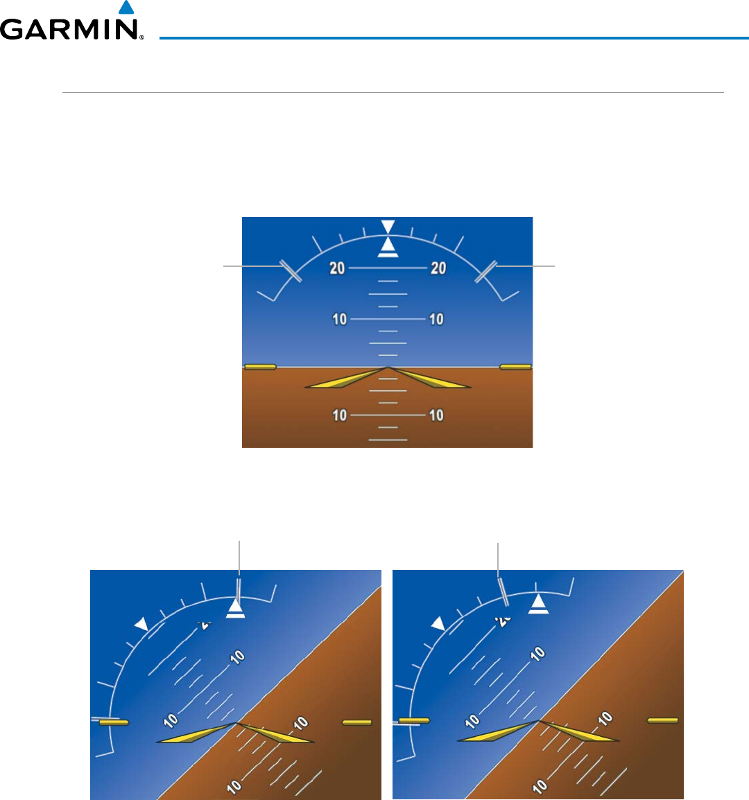
Garmin G1000 Pilot’s Guide for the Beechcraft 200/B200 Series
190-00928-04 Rev. A 651
ADDITIONAL FEATURES
ROLL ENGAGEMENT
Roll Limit Indicators are displayed on the roll scale at 45° right and left, indicating where ESP will engage
(see Figure 8-122). As roll attitude exceeds 45°, ESP will engage and the on-side Roll Limit Indicator will move
to 30°, as shown in Figure 8-123. The Roll Limit Indicator is now showing where ESP will disengage as roll
attitude decreases.
Roll Limit Indicator
ESP Engage (45°)
Figure 8-122 ESP Roll Engagement Indication (ESP NOT Engaged)
Roll Limit Indicator
ESP Engage (45°)
Before ESP Engage After ESP Engage
ESP Engage (45°)
Aircraft Roll Attitude = 44° ESP Disengage (30°)
Aircraft Roll Attitude = 46°
Figure 8-123 Roll Increasing to ESP Engagement
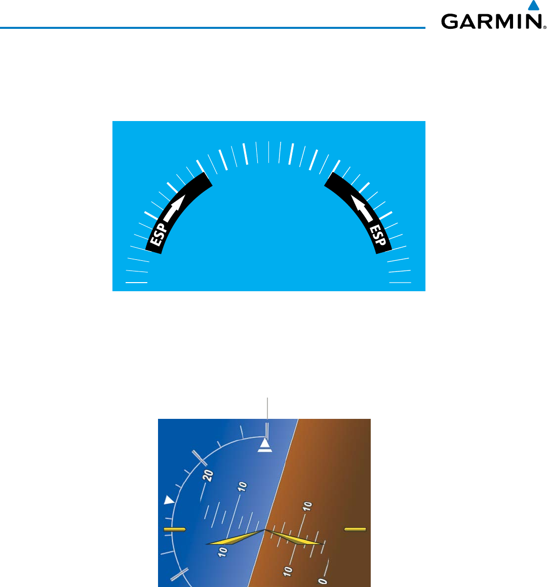
Garmin G1000 Pilot’s Guide for the Beechcraft 200/B200 Series
190-00928-04 Rev. A652
ADDITIONAL FEATURES
Once engaged, ESP force will be applied between 30° and 75°, as illustrated in Figure 8-124. The force
increases as roll attitude increases and decreases as roll attitude decreases. The applied force is intended to
encourage pilot input that returns the airplane to a more normal roll attitude. As roll attitude decreases, ESP
will disengage at 30°.
Figure 8-124 ESP Roll Operating Range When Engaged
(Force Increases as Roll Increases & Decreases as Roll Decreases)
0º
10º
10º
20º
20º
30º
30º
45º
45º
60º
60º
75º
75º
90º
90º
ESP is automatically disengaged if the aircraft reaches the autopilot roll engagement attitude limit of 75°
(Figure 8-125).
Figure 8-125 Roll Attitude Autopilot Engagement Limit (ESP Engaged)
ESP Upper Disengage Limit (75°)
Aircraft Roll Attitude = 74°
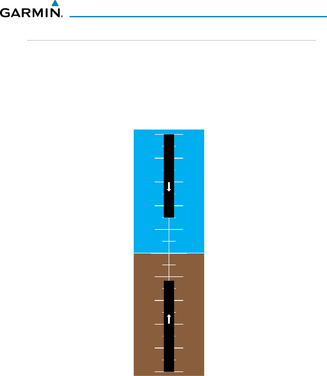
Garmin G1000 Pilot’s Guide for the Beechcraft 200/B200 Series
190-00928-04 Rev. A 653
ADDITIONAL FEATURES
PITCH ENGAGEMENT
ESP engages at 20° nose-up and 17° nose-down. Once ESP is engaged, it will apply opposing force between
15° and 50° nose-up and between 12° and 50° nose-down, as indicated in Figure 8-126. Maximum opposing
force is applied between 25° and 50° nose-up and between 22° and 50° nose-down.
The opposing force increases or decreases depending on the pitch angle and the direction of pitch travel. This
force is intended to encourage movement in the pitch axis in the direction of the normal pitch attitude range
for the aircraft.
There are no indications marking the pitch ESP engage and disengage limits in these nose-up/nose-down
conditions.
Figure 8-126 ESP Pitch Operating Range When Engaged
(Force Increases as Pitch Increases & Decreases as Pitch Decreases)
30˚
25˚
20˚
15˚
10˚
5˚
0˚
5˚
10˚
15˚
20˚
25˚
30˚
30˚
25˚
20˚
15˚
10˚
5˚
0˚
5˚
10˚
15˚
20˚
25˚
30˚
35˚
40˚
45˚
50˚
35˚
40˚
45˚
50˚
50˚
45˚
40˚
35˚
50˚
45˚
40˚
35˚
ESPESP
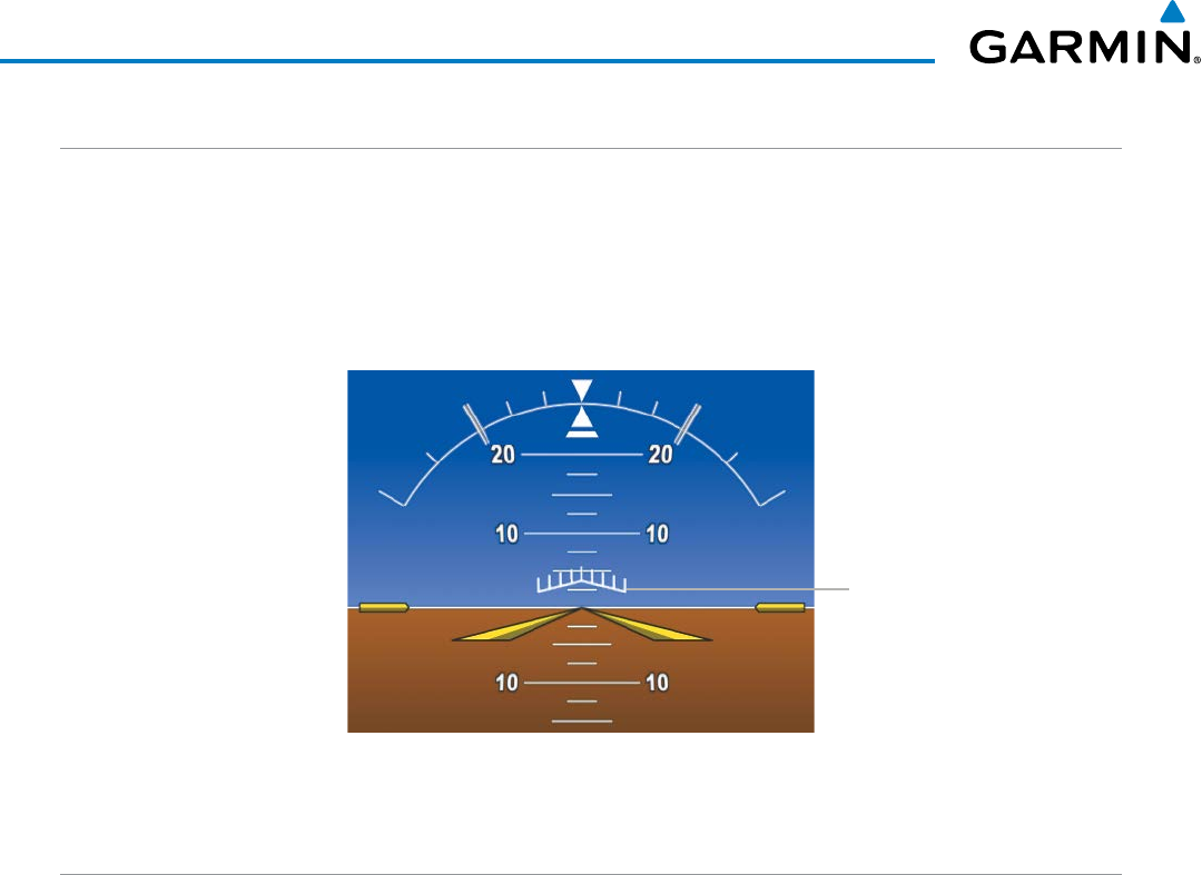
Garmin G1000 Pilot’s Guide for the Beechcraft 200/B200 Series
190-00928-04 Rev. A654
ADDITIONAL FEATURES
ANGLE OF ATTACK PROTECTION
When a compatible lift computer is installed with the G1000 retrofit, angle of attack protection is provided
as part of the ESP feature. ESP force may be applied if the lift computer determines a stall warning condition is
imminent. In this condition, the Pitch Limit Indicator will be initially displayed 4° below this computed pitch
attitude (Figure 8-127). When pitch attitude equals that indicated by the Pitch Limit Indicator, ESP will engage,
applying a force in the direction necessary to lower the nose of the aircraft.
Figure 8-127 Pitch Limit Indicator
Pitch Limit Indicator
HIGH AIRSPEED PROTECTION
Exceeding Vmo or Mmo will result in ESP applying force to raise the nose of the aircraft. When the high
airspeed condition is remedied, ESP force is no longer applied.
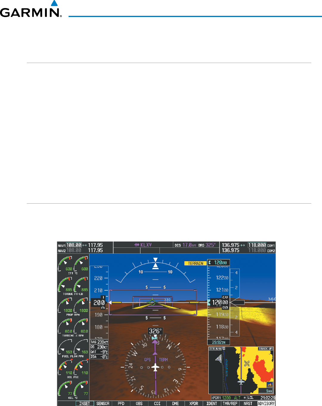
Garmin G1000 Pilot’s Guide for the Beechcraft 200/B200 Series
190-00928-04 Rev. A 655
ADDITIONAL FEATURES
8.12 ABNORMAL OPERATION
SVT TROUBLESHOOTING
SVT is intended to be used with traditional attitude, heading, obstacle, terrain, and traffic inputs. SVT is
disabled when valid attitude or heading data is not available for the display. In case of invalid SVT data, the
PFD display reverts to the standard blue-over-brown attitude display.
SVT becomes disabled without the following data resources:
• Attitude data
• Heading data
• GPS position data
• 9 Arc-second Terrain data
• Obstacle data
• TAWS function is not available, in test mode, or failed
• The position of the aircraft exceeds the range of the terrain database.
REVERSIONARY MODE
SVT can be displayed on the Multifunction Display (MFD) in Reversionary Mode. If it is enabled when switching
to Reversionary Mode, SVT will take up to 30 seconds to be displayed. The standard, non-SVT PFD display will
be shown in the interim.
Figure 8-128 SVT Reversionary Mode
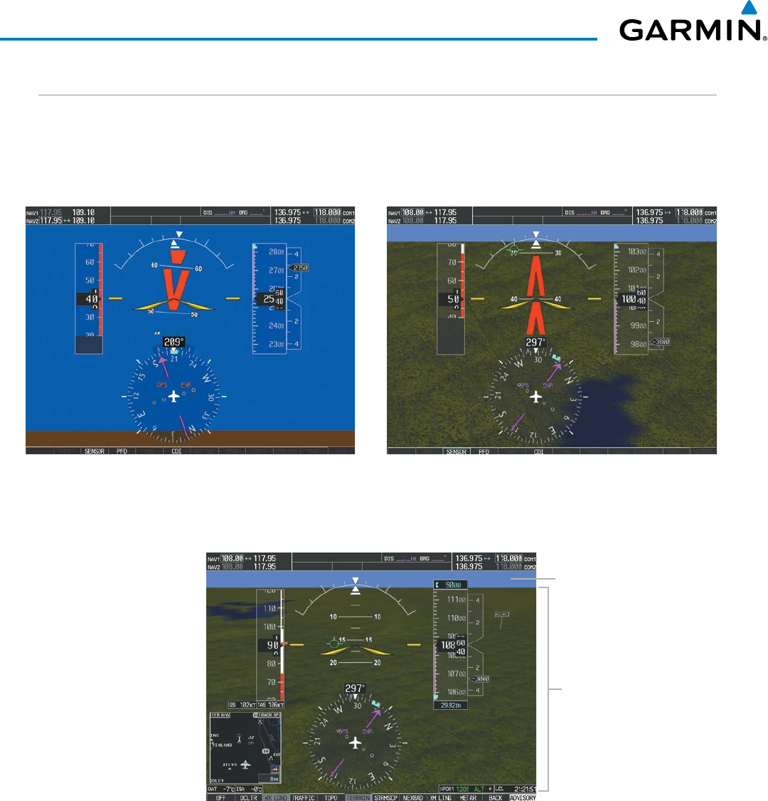
Garmin G1000 Pilot’s Guide for the Beechcraft 200/B200 Series
190-00928-04 Rev. A656
ADDITIONAL FEATURES
UNUSUAL ATTITUDES
Unusual attitudes are displayed with red chevrons overlaid on the display indicating the direction to fly to
correct the unusual attitude condition. The display shows either a brown or blue colored bar at the top or
bottom of the screen to represent earth or sky. This is intended to prevent losing sight of the horizon during
extreme pitch attitudes.
Figure 8-129 Unusual Attitude Display
The blue colored bar is also displayed when terrain gradient is great enough to completely fill the display.
Blue Band
Figure 8-130 Blue Sky Bar with Full Display Terrain
Terrain
Completely
Fills Display
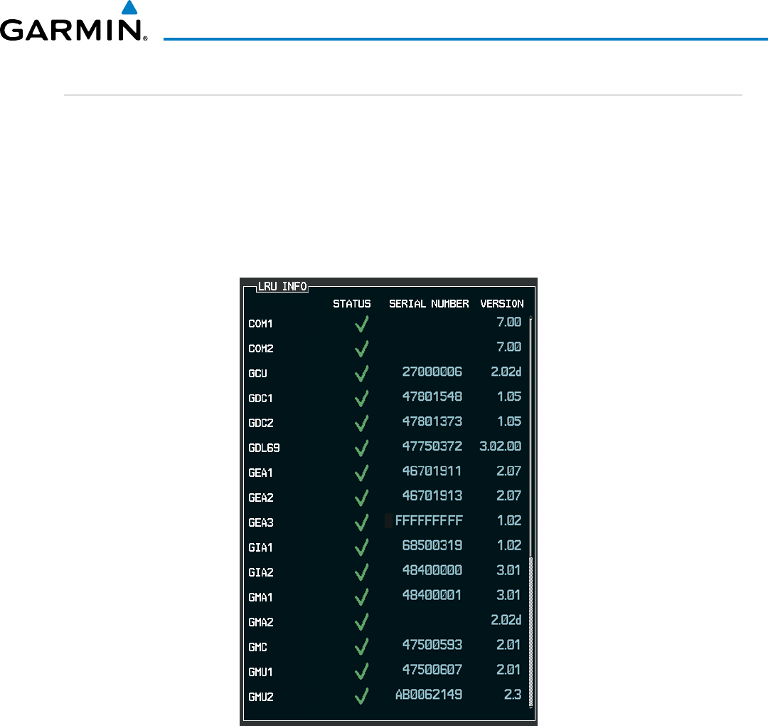
Garmin G1000 Pilot’s Guide for the Beechcraft 200/B200 Series
190-00928-04 Rev. A 657
ADDITIONAL FEATURES
GSR 56 & GDL 59/69/69A TROUBLESHOOTING
For troubleshooting purposes, check the LRU Information Box on the AUX - System Status Page for GSR 56,
GDL 59, or GDL 69/69A status, serial number, and software version number. If a failure has been detected in
the GDL 69/69A the status is marked with a red X.
Selecting the AUX - System Status Page:
1) Turn the large FMS Knob to select the AUX Page Group.
2) Turn the small FMS Knob to select the AUX ‑ System Status Page.
Figure 8-131 LRU Information Window on System Status Page
Some quick troubleshooting steps listed below can be performed to find the possible cause of a failure.
• Ensure the installed Data Link Receiver or Iridium Trasceiver has an active subscription or account
• Perform a quick check of the circuit breakers to ensure that power is applied to the Data Link Receiver or
Iridium Transceiver
Garmin G1000 Pilot’s Guide for the Beechcraft 200/B200 Series
190-00928-04 Rev. A658
ADDITIONAL FEATURES
GDL 69/69A
Ensure that nothing is plugged into the MUSIC 1 or MUSIC 2 jacks because that would prevent SiriusXM
radio from being heard
If a failure still exists, the following messages may provide insight as to the possible problem:
Message Message Location Description
CHECK ANTENNA XM Information Page (MFD) Data Link Receiver antenna error; service
required
UPDATING XM Information Page (MFD)) Data Link Receiver updating encryption code
NO SIGNAL XM Information Page Weather Datalink Page
(MFD)
Loss of signal; signal strength too low for
receiver
LOADING XM Radio Page (MFD) Acquiring channel audio or information
OFF AIR XM Radio Page (MFD) Channel not in service
-------- XM Radio Page (MFD) Missing channel information
WEATHER DATA LINK FAILED Weather Datalink Page (MFD) No communication from Data Link Receiver
within last 5 minutes
ACTIVATION REQUIRED XM Information Page (MFD) SiriusXM subscription is not activated
DETECTING ACTIVATION Weather Datalink Page (MFD) SiriusXM subscription is activating.
WAITING FOR DATA... Weather Datalink Page (MFD) SiriusXM subscription confirmed downloading
weather data.
Table 8-7 GDL 69/69A Data Link Receiver Messages
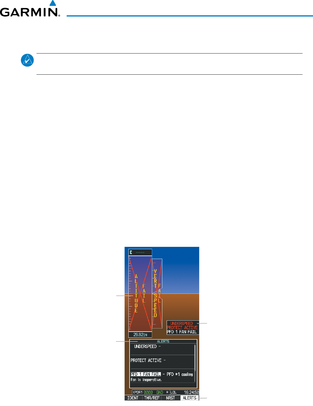
190-00928-04 Rev. A
Garmin G1000 Pilot’s Guide for the Beechcraft 200/B200 Series
659
APPENDIX A
ANNUNCIATIONS AND ALERTS
NOTE:
The Pilot’s Operating Handbook and FAA Approved Airplane Flight Manual (AFM/POH) supersedes
information found in this document.
The G1000 Alerting System conveys alerts using the following:
•
Annunciation Window:
The Annunciation Window displays abbreviated annunciation text. Text color is based
on alert levels described later in the Alert Levels Definitions section. The Annunciation Window is located to the
right of the Altitude and Vertical Speed boxes on the display. All annunciations can be displayed simultaneously
in the Annunciation Window. A white horizontal line separates annunciations that are acknowledged from
annunciations that are not yet acknowledged. Higher priority annunciations are displayed towards the top of
the window. Lower priority annunciations are displayed towards the bottom of the window.
• Alerts Window: The Alerts Window displays text messages for up to 64 prioritized alert messages. Pressing
the ALERTS Softkey displays the Alerts Window. Pressing the ALERTS Softkey a second time removes the
Alerts Window from the display. When the Alerts Window is displayed, the FMS Knob can be used to scroll
through the alert message list.
• Softkey Annunciation: During certain alerts, the ALERTS Softkey may appear as a flashing annunciation to
accompany an alert. The ALERTS Softkey assumes a new label (ADVISORY). By selecting the softkey when
flashing an annunciation, the alert is acknowledged. The softkey label then returns to ALERTS. If alerts are
still present, the ALERTS label is displayed in white with black text. Selecting the ALERTS Softkey a second
time views the alert text messages.
• System Annunciations: Typically, a large red ‘X’ appears over instruments whose information is supplied by
a failed Line Replaceable Unit (LRU). See the G1000 System Annunciations Section for more information.
System
Annunciation
(Red ‘X’)
Alerts
Window
Figure A-1 G1000 Alerting System
Softkey
Annunciation
Annunciation
Window
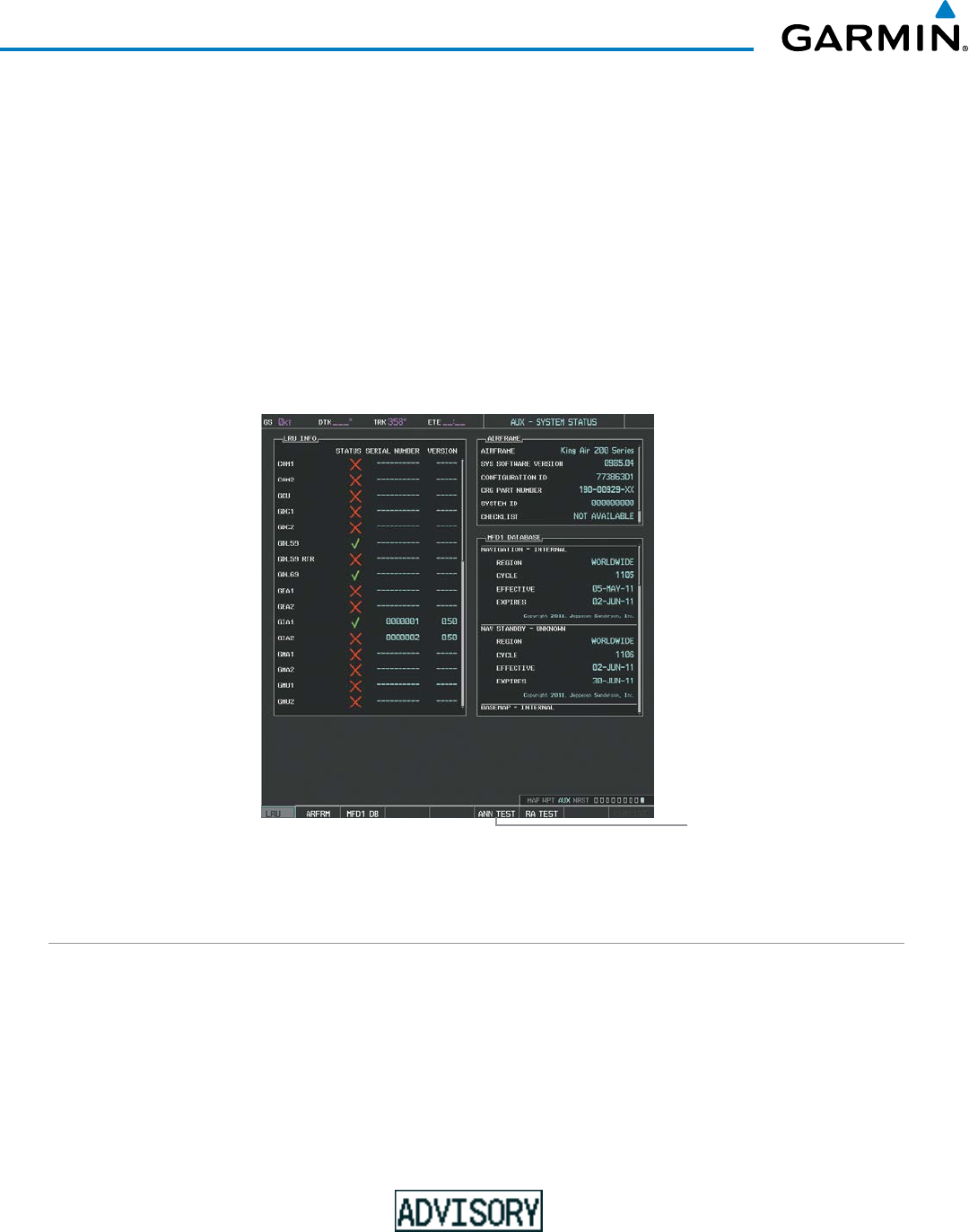
Garmin G1000 Pilot’s Guide for the Beechcraft 200/B200 Series
190-00928-04 Rev. A660
APPENDIX A
• Audio Alerting System: The G1000 System issues audio alert tones when specific system conditions are met.
See the Alert Level Definitions Section for more information. The annunciation tone may be tested from the
AUX - System Status Page.
Testing the system annunciation tone and annunciator lights:
1) Use the FMS Knob to select the AUX - System Status Page.
2) Select the ANN TEST Softkey.
Or:
a) Press the MENU Key.
b) Highlight ‘Enable Annunciator Test Mode’ and press the ENT Key.
Figure A-2 System Status Page, System Annunciation Testing
Press to Test
Annunciation Tone and
Annunciation Lights
ALERT LEVEL DEFINITIONS
The G1000 Alerting System, as installed in Beechcraft 200/B200 Series aircraft, uses one alert level.
• ANNUNCIATION OR MESSAGE ADVISORY: This level of alert provides general information.
An annunciation alert is accompanied by a flashing ‘ADVISORY’ Softkey annunciation (see Figure A-3).
Pressing the ADVISORY Softkey acknowledges the presence of the annunciation alert.
Message advisory alerts issue a flashing ‘ADVISORY’ Softkey annunciation (see Figure A-3). Pressing the
ADVISORY Softkey acknowledges the presence of the message advisory alert and displays the alert text
message in the Alerts Window.
Figure A-3 Softkey Annunciation (ALERTS Softkey Labels)
190-00928-04 Rev. A
Garmin G1000 Pilot’s Guide for the Beechcraft 200/B200 Series
661
APPENDIX A
AIRCRAFT ALERTS
The following alerts are configured specifically for the Beechcraft 200/B200 Series. Red annunciation window
text signifies warnings. White annunciation window text signifies advisories. See the Aircraft Flight Manual
(AFM) for recommended pilot actions.
WARNING ANNUNCIATIONS
Annunciation Window Text Alerts Window Message Audio Alert
UNDERSPEED
PROTECT ACTIVE
None None
ADVISORY ANNUNCIATIONS
Annunciation Window Text Alerts Window Message Audio Alert
AVN FAN 1 FAIL
Avionics cooling fan #1 is inoperative.
None
AVN FAN 2 FAIL
Avionics cooling fan #2 is inoperative.
None
MFD FAN FAIL
MFD cooling fan is inoperative.
None
PFD 1 FAN FAIL
PFD #1 cooling fan is inoperative.
None
PFD 2 FAN FAIL
PFD #2 cooling fan is inoperative.
None
MESSAGE ADVISORY ALERTS
Advisory alerts issue a flashing ‘ADVISORY’ Softkey annunciation. Pressing the ADVISORY Softkey
acknowledges the presence of the advisory alert and displays the alert text message in the Alerts Window.
Alerts Window Message Audio Alert/Voice Message
TAWS GEAR FAULT – Landing Gear detected in the DOWN position. None
TAWS FLAP FAULT
– Flaps detected in the LDG position. None
WOW FAULT – Miscompare between weight on wheels inputs. None
WOW INVALID – Weight on wheels inputs invalid. None
ESP OFF – ESP selected off. None
ESP FAIL – ESP is inoperative. None
ESP DEGRADE – ESP AOA mode is inoperative*. None
ESP DEGRADE – ESP IAS mode is inoperative. None
ESP CONFIG
– ESP config error. Config service req’d. None
YD OFF – AP engaged without Yaw Damper None
*only available when compatible lift computer is installed.

Garmin G1000 Pilot’s Guide for the Beechcraft 200/B200 Series
190-00928-04 Rev. A662
APPENDIX A
VOICE ALERTS
The following voice alerts are announced by the system using a male or female gender (see the AUX -
System Setup Page for the default configured voice gender; contact a Garmin-authorized service center to
change the audio alert voice). Terrain Awareness and Warning System voice alerts are also generated (refer
to the TAWS Alerts section).
Voice Alert Description
“Minimums” The aircraft has descended below the preset minimum descent altitude or decision
altitude.
“Vertical track” The aircraft is one minute from Top of Descent. Issued only when vertical navigation is
enabled.
“Airspeed” The aircraft is in an underspeed condition. See the AFCS section for more details.
“Engaging autopilot” The ESP system is engaging the autopilot. See the AFCS section for more details.
“Traffic” Played when a Traffic Advisory (TA) is issued with the TIS system, the optional GTS
800/820/825 TAS system, or the optional GTS 850/855 TCAS I system. See the Hazard
Avoidance section for additional details on GTS 800/820/825/850/855 voice alerts.
“TIS Not Available” The aircraft is outside the Traffic Information Service (TIS) coverage area.
“Traffic, Traffic”
“Traffic”
Played when a Traffic Advisory (TA) is issued with the optional SKY 497/SKY899 TAS
system, or the optional KTA 870 TAS system. See the Skywatch PG or KTA 870 PG for
additional details on voice alerts.
Played for each subsequent TA (KTA 870 only).
“Traffic Advisory System Test Passed”
“SKYWATCH System Test Passed”
“TAS System Test OK”
“TAS System Test Passed”
“TCAS System Test Passed”
“TCAS One System Test Passed”
“TCAS Two System Test Passed”
Played when the optional traffic system passes a pilot-initiated self test.
- SKY 497 TAS
- SKY 899 TAS
- KTA 870 TAS
- GTS 800/820/825 TAS
- GTS 850 TCAS I
- GTS 855 TCAS I
- GTS 8000 TCAS II
“Traffic Advisory System Test Failed”
“SKYWATCH System Test Failed”
“TAS System Test Fail”
“TAS System Test Failed”
“TCAS System Test Failed”
“TCAS One System Test Failed”
“TCAS Two System Test Failed”
Played when the optional traffic system fails a pilot-initiated self test.
- SKY 497 TAS
- SKY 899 TAS
- KTA 870 TAS
- GTS 800/820/825 TAS
- GTS 850 TCAS I
- GTS 855 TCAS I
- GTS 8000 TCAS II
“One o’clock” through
“Twelve o’clock”
or “No Bearing”
Intruder bearing (GTS 800/820/825/850/855 only)
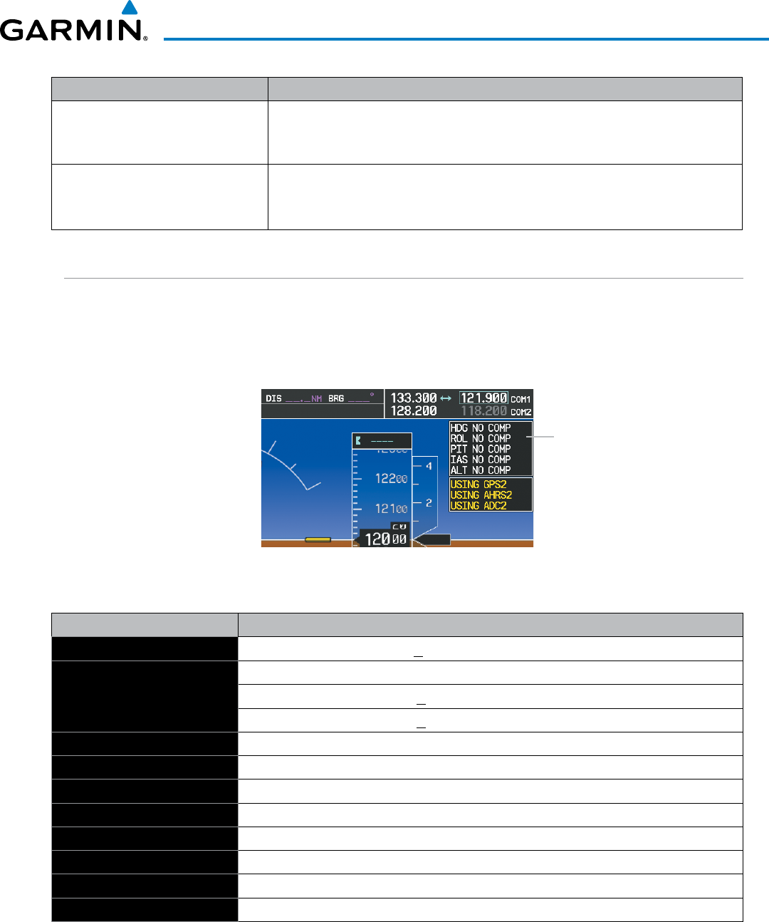
190-00928-04 Rev. A
Garmin G1000 Pilot’s Guide for the Beechcraft 200/B200 Series
663
APPENDIX A
Voice Alert Description
“High”, “Low”, “Same Altitude” (if
within 200 feet of own altitude), or
“Altitude not available”
Intruder relative altitude (GTS 800/820/825/850/855 only)
“Less than one mile”,
“One Mile” through “Ten Miles”, or
“More than ten miles”
Intruder distance (GTS 800/820/825/850/855 only)
COMPARATOR ANNUNCIATIONS
The Comparator monitors critical values generated by redundant sensors. If differences in the sensors exceed
a specified amount, this discrepancy is annunciated in the Comparator Window as a ‘MISCOMP’ (miscompare).
If one or both of the sensed values are unavailable, it is annunciated as a ‘NO COMP’ (no compare) as seen in
Figure A-4. The following is a list of the possible annunciations:
Figure A-4 Sensor Comparator Window
Comparator
Window
Comparator Window Text Condition
ALT MISCOMP
Difference in altitude sensors is > 200 ft.
IAS MISCOMP
If both airspeed sensors detect < 35 knots, this is inhibited.
If either airspeed sensor detects > 35 knots, and the difference in sensors is > 10 knots.
If either airspeed sensor detects > 80 knots, and the difference in sensors is > 7 knots.
HDG MISCOMP
Difference in heading sensors is > 6 degrees.
PIT MISCOMP
Difference in pitch sensors is > 5 degrees.
ROL MISCOMP
Difference in roll sensors is > 6 degrees.
ALT NO COMP
No data from one or both altitude sensors.
IAS NO COMP
No data from one or both airspeed sensors.
HDG NO COMP
No data from one or both heading sensors.
PIT NO COMP
No data from one or both pitch sensors.
ROL NO COMP
No data from one or both roll sensors..
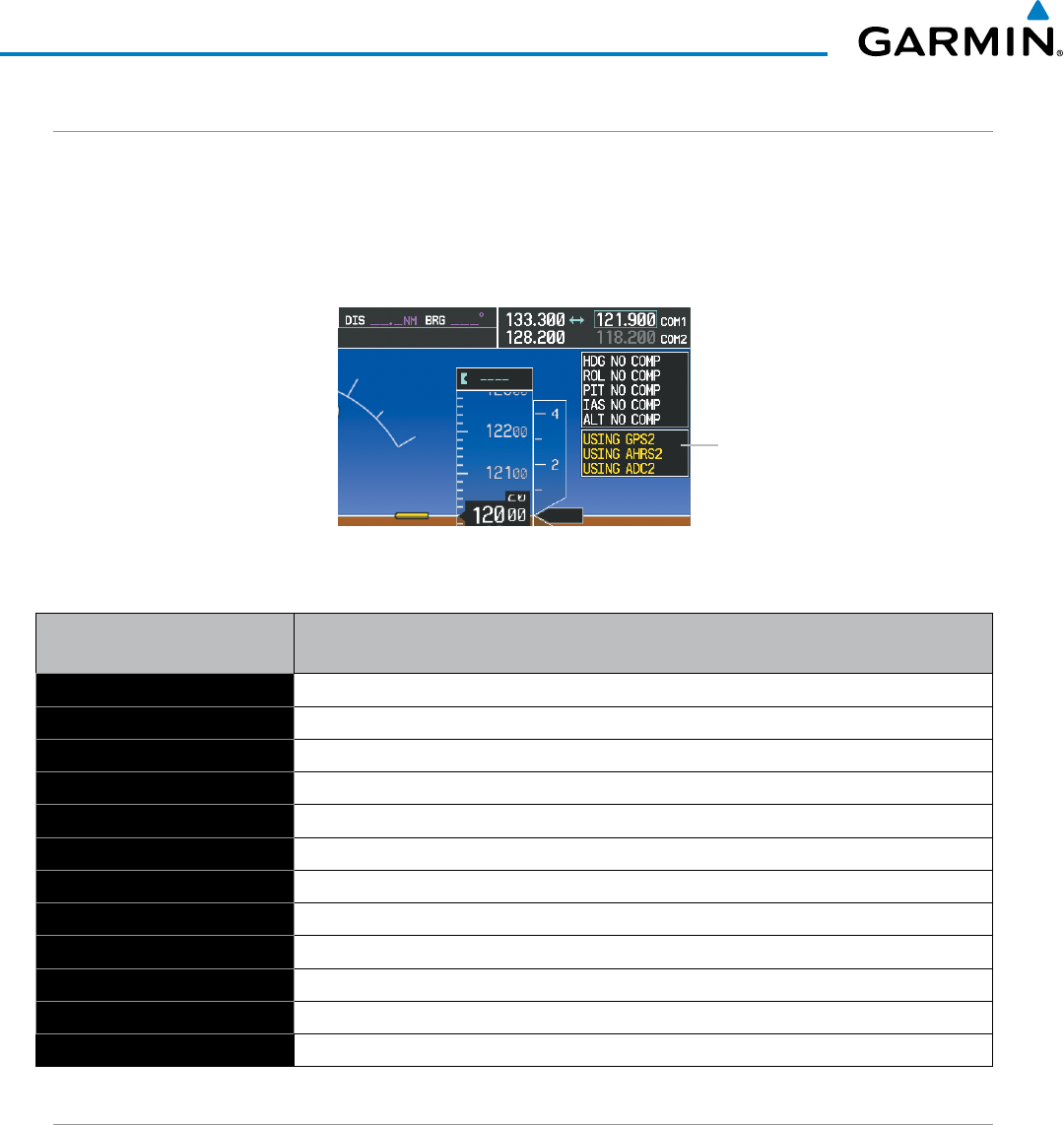
Garmin G1000 Pilot’s Guide for the Beechcraft 200/B200 Series
190-00928-04 Rev. A664
APPENDIX A
REVERSIONARY SENSOR ANNUNCIATIONS
Reversionary sensor selection is annunciated in the Reversionary Sensor Window, as shown in Figure A-5.
These annunciations reflect reversionary sensors selected on one or both PFDs. Pressing the
SENSOR
Softkey
gives access to
ADC1
,
ADC2
,
AHRS1
, and
AHRS2
Softkeys. These softkeys allow manual switching of sensors. In
the case of certain types of sensor failures, the G1000 may make some sensor selections automatically. The GPS
sensor cannot be switched manually.
Figure A-5 Reversionary Sensor Windows
Reversionary
Sensor
Window
Reversionary Sensor
Window Text
Condition
BOTH ON ADC1 Both PFDs are displaying data from the number one Air Data Computer.
BOTH ON ADC2 Both PFDs are displaying data from the number two Air Data Computer.
BOTH ON AHRS1 Both PFDs are displaying data from the number one Attitude & Heading Reference System.
BOTH ON AHRS2 Both PFDs are displaying data from the number two Attitude & Heading Reference System.
BOTH ON GPS1 Both PFDs are displaying data from the number one GPS receiver.
BOTH ON GPS2 Both PFDs are displaying data from the number two GPS receiver.
USING ADC1 PFD2 is displaying data from the #1 Air Data Computer.
USING ADC2 PFD1 is displaying data from the #2 Air Data Computer.
USING AHRS1 PFD2 is displaying data from the #1 AHRS.
USING AHRS2 PFD1 is displaying data from the #2 AHRS.
USING GPS1 PFD2 is displaying data from the #1 GPS.
USING GPS2 PFD1 is displaying data from the #2 GPS.
G1000 SYSTEM ANNUNCIATIONS
When a new message is issued, the
ALERTS
Softkey flashes to alert the flight crew of a new message. It
continues to flash until acknowledged by pressing the softkey. Active messages are displayed in white text.
Messages that have become inactive change to gray text. The
ALERTS
Softkey flashes if the state of a displayed
message changes or a new message is displayed. The inactive messages can be removed from the Message
Window by pressing the flashing
ALERTS
Softkey.
The G1000 System Messages convey messages to the flight crew regarding problems with the G1000 system.
Typically, a large red ‘X’ appears in a window when a related LRU fails or detects invalid data.
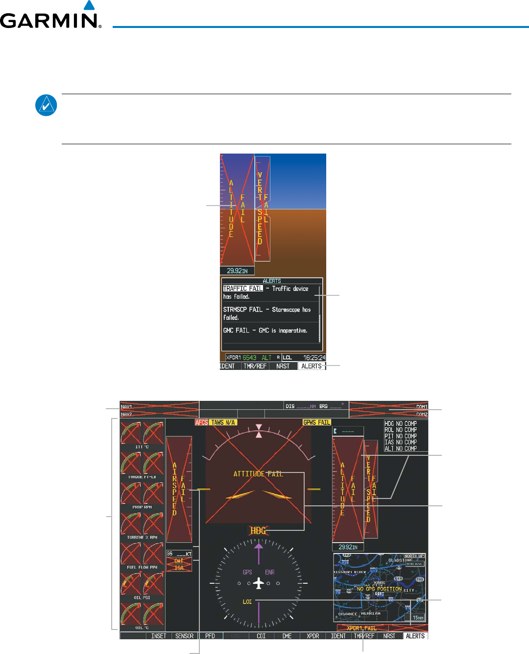
190-00928-04 Rev. A
Garmin G1000 Pilot’s Guide for the Beechcraft 200/B200 Series
665
APPENDIX A
The following section describes various system annunciations. Refer to the AFM/POH for additional
information regarding pilot responses to these annunciations.
NOTE
: Upon power-up of the G1000 system, certain windows remain invalid as G1000 equipment begins to
initialize. All windows should be operational within one minute of power-up. Should any window continue
to remain flagged, the G1000 system should be serviced by a Garmin-authorized repair facility.
Figure A-6 G1000 System Messages
Messages Window
Alerts Softkey Annunciation
System
Annunciation
Red ‘X’
Figure A-7 G1000 System Failure Annunciations
GDC 74B Air
Data Computer
GTX 33 Transponder Or GIA 63W Integrated Avionics Units
GDC 74B Air Data Computer
GEA 71 Engine
Airframe Unit
Or
GIA 63W
Integrated
Avionics Unit
GIA 63W
Integrated
Avionics Units
GIA 63W
Integrated
Avionics Units
GIA 63W
Integrated
Avionics Units
GRS 77 AHRS
Or
GMU 44
Magnetometer
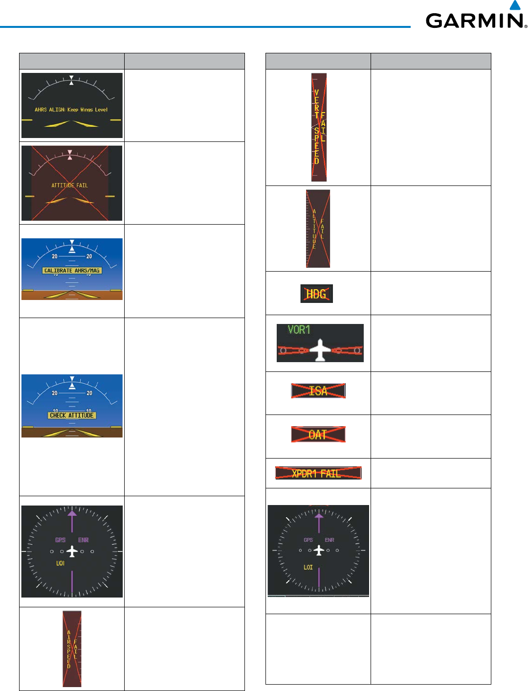
Garmin G1000 Pilot’s Guide for the Beechcraft 200/B200 Series
190-00928-04 Rev. A666
APPENDIX A
System Annunciation Comment
Attitude and Heading
Reference System is aligning.
Display system is not receiving
attitude information from the
AHRS.
AHRS calibration incomplete
or configuration module
failure.
This annunciation is only
seen when the autopilot is
engaged. The annunciation
indicates an AHRS monitor
has detected an abnormal
flight parameter, possibly
caused by strong turbulence.
In this case, the situation
should correct itself within a
few seconds. If there is an
actual failure, a red “X” soon
appears over the Attitude
Indicator.
GPS information is either
not present or is invalid for
navigation use. Note that
AHRS utilizes GPS inputs
during normal operation.
AHRS operation may be
degraded if GPS signals are
not present (see POH).
Display system is not receiving
airspeed input from air data
computer.
System Annunciation Comment
Display system is not receiving
vertical speed input from the
air data computer.
Display system is not receiving
altitude input from the air
data computer.
Display system is not receiving
valid heading input from
AHRS.
CDI is not receiving valid data
from the corresponding GIA.
Does not apply when the CDI
is set to GPS.
Display system is not receiving
valid ISA information from air
data computer.
Display system is not receiving
valid OAT information from air
data computer.
Display system is not receiving
valid transponder information.
GPS information is either
not present or is invalid for
navigation use.
Note that AHRS utilizes
GPS inputs during normal
operation. AHRS operation
may be degraded if GPS
signals are not present (see
AFM/POH).
Other Various Red X
Indications
A red ‘X’ through any other
display field (such as engine
instrumentation display)
indicates that the field is not
receiving valid data.

190-00928-04 Rev. A
Garmin G1000 Pilot’s Guide for the Beechcraft 200/B200 Series
667
APPENDIX A
G1000 SYSTEM MESSAGE ADVISORIES
This section describes various G1000 system message advisories. Certain messages are issued due to an LRU
or an LRU function failure. Such messages are normally accompanied by a corresponding red ‘X’ annunciation
as shown previously in the G1000 System Annunciation section.
NOTE: This Section provides information regarding G1000 message advisories that may be displayed by
the system. Knowledge of the aircraft, systems, flight conditions, and other existing operational priorities
must be considered when responding to a message. Always use sound pilot judgment. The AFM/POH takes
precedence over any conflicting guidance found in this section.
MFD & PFD MESSAGE ADVISORIES
Message Comments
DATA LOST
– Pilot stored data was
lost. Recheck settings.
The pilot profile data was lost. System reverts to default pilot profile and settings. The
pilot may reconfigure the MFD & PFD with preferred settings, if desired.
XTALK ERROR
– A flight display
crosstalk error has occurred.
The MFD and PFD are not communicating with each other. The G1000 system should
be serviced.
PFD1 SERVICE
– PFD1 needs service.
Return unit for repair.
The PFD and/or MFD self-test has detected a problem. The G1000 system should be
serviced.
PFD2 SERVICE
– PFD2 needs service.
Return unit for repair.
MFD1 SERVICE
– MFD1 needs
service. Return unit for repair.
MANIFEST
– PFD1 software
mismatch. Communication halted.
The PFD and/or MFD has incorrect software installed. The G1000 system should be
serviced.
MANIFEST
– PFD2 software
mismatch. Communication halted.
MANIFEST
– MFD1 software
mismatch. Communication halted.
PFD1 CONFIG
– PFD1 configuration
error. Config service req’d. The PFD configuration settings do not match backup configuration memory. The
G1000 system should be serviced.
PFD2 CONFIG
– PFD2 configuration
error. Config service req’d.
MFD1 CONFIG
– MFD1 configuration
error. Config service req’d.
The MFD configuration settings do not match backup configuration memory. The
G1000 system should be serviced.
PFD1 SOFTWARE
– PFD1 mismatch,
communication halted.
The specified GDU has different software versions installed. The system should be
serviced.
PFD2 SOFTWARE
– PFD2 mismatch,
communication halted.
MFD1 SOFTWARE
– MFD1 mismatch,
communication halted.

Garmin G1000 Pilot’s Guide for the Beechcraft 200/B200 Series
190-00928-04 Rev. A668
APPENDIX A
Message Comments
PFD1 COOLING
– PFD1 has poor
cooling. Reducing power usage.
The PFD and/or MFD is overheating and is reducing power consumption by dimming
the display. If problem persists, the G1000 system should be serviced.
PFD2 COOLING
– PFD2 has poor
cooling. Reducing power usage.
MFD1 COOLING
– MFD1 has poor
cooling. Reducing power usage.
PFD1 KEYSTK
– PFD1 [key name] Key
is stuck.
A key is stuck on the PFD and/or MFD bezel. Attempt to free the stuck key by pressing
it several times. The G1000 system should be serviced if the problem persists.
PFD2 KEYSTK
– PFD2 [key name] Key
is stuck
MFD1 KEYSTK
– MFD1 [key name]
Key is stuck.
CNFG MODULE
– PFD1 configuration
module is inoperative.
The PFD1 configuration module backup memory has failed. The G1000 system should
be serviced.
PFD1 VOLTAGE
– PFD1 has low
voltage. Reducing power usage. The PFD1 voltage is low. The G1000 system should be serviced.
PFD2 VOLTAGE
– PFD2 has low
voltage. Reducing power usage. The PFD2 voltage is low. The G1000 system should be serviced.
MFD1 VOLTAGE
– MFD1 has low
voltage. Reducing power usage. The MFD voltage is low. The G1000 system should be serviced.
[PFD1, PFD2, or MFD1] BKLT CAL INV
– calibration lost or mismatch. Return
for repair.
The PFD1, PFD2 and/or MFD backlight calibration cannot be found or is invalid. The
system should be serviced.
DATABASE MESSAGE ADVISORIES
Message Comments
MFD1 DB ERR
– MFD1 navigation
database error exists. The MFD and/or PFD detected a failure in the navigation database. Attempt to
reload the navigation database. If problem persists, the G1000 system should be
serviced.
PFD1 DB ERR
– PFD1
navigation database error exists.
PFD2 DB ERR
– PFD2
navigation database error exists.
MFD1 DB ERR
– MFD1 basemap
database error exists.
The MFD and/or PFD detected a failure in the basemap database. The G1000 system
should be serviced.
PFD1 DB ERR
– PFD1 basemap
database error exists.
PFD2 DB ERR
– PFD2 basemap
database error exists.
MFD1 DB ERR
– MFD1 terrain
database error exists. The MFD and/or PFD detected a failure in the terrain database. Ensure that the
terrain card is properly inserted in display. Replace terrain card. If problem persists,
the G1000 system should be serviced.
PFD1 DB ERR
– PFD1 terrain database
error exists.
PFD2 DB ERR
– PFD2 terrain database
error exists.

190-00928-04 Rev. A
Garmin G1000 Pilot’s Guide for the Beechcraft 200/B200 Series
669
APPENDIX A
Message Comments
MFD1 DB ERR
– MFD1 terrain
database missing. The terrain database is present on another LRU, but is missing on the specified LRU.
Ensure that the terrain card is properly inserted in the specified display. Replace
terrain card. If problem persists, the G1000 system should be serviced.
PFD1 DB ERR
– PFD1 terrain database
missing.
PFD2 DB ERR
– PFD2 terrain database
missing.
MFD1 DB ERR
– MFD1 obstacle
database error exists. The MFD and/or PFD detected a failure in the obstacle database. Ensure that the
data card is properly inserted. Replace data card. If problem persists, the G1000
system should be serviced.
PFD1 DB ERR
– PFD1 obstacle
database error exists.
PFD2 DB ERR
– PFD2 obstacle
database error exists.
MFD1 DB ERR
– MFD1 obstacle
database missing. The obstacle database is present on another LRU, but is missing on the specified
LRU. Ensure that the terrain card is properly inserted in the specified display.
Replace terrain card. If problem persists, the G1000 system should be serviced.
PFD1 DB ERR
– PFD1 obstacle
database missing.
PFD2 DB ERR
– PFD2 obstacle
database missing.
MFD1 DB ERR
– MFD1 airport terrain
database error exists. The MFD and/or PFD detected a failure in the airport terrain database. Ensure that
the data card is properly inserted. Replace data card. If problem persists, the G1000
system should be serviced.
PFD1 DB ERR
– PFD1 airport terrain
database error exists.
PFD2 DB ERR
– PFD2 airport terrain
database error exists.
MFD1 DB ERR
– MFD1 airport terrain
database missing. The airport terrain database is present on another LRU, but is missing on the
specified LRU. Ensure that the terrain card is properly inserted in the specified
display. Replace terrain card. If problem persists, the G1000 system should be
serviced.
PFD1 DB ERR
– PFD1 airport terrain
database missing.
PFD2 DB ERR
– PFD2 airport terrain
database missing.
MFD1 DB ERR
– MFD1 Safe Taxi
database error exists. The MFD and/or PFD detected a failure in the Safe Taxi database. Ensure that the
data card is properly inserted. Replace data card. If problem persists, the G1000
system should be serviced.
PFD1 DB ERR
– PFD1 Safe Taxi
database error exists.
PFD2 DB ERR
– PFD2 Safe Taxi
database error exists.
MFD1 DB ERR
– MFD1 Chartview
database error exists.
The MFD detected a failure in the Chartview database (optional feature). Ensure that
the data card is properly inserted. Replace data card. If problem persists, the G1000
system should be serviced.
MFD1 DB ERR
– MFD1 FliteCharts
database error exists.
The MFD detected a failure in the FliteCharts database (optional feature). Ensure
that the data card is properly inserted. Replace data card. If problem persists, the
G1000 system should be serviced.

Garmin G1000 Pilot’s Guide for the Beechcraft 200/B200 Series
190-00928-04 Rev. A670
APPENDIX A
Message Comments
MFD1 DB ERR
– MFD1 Airport
Directory database error exists.
The MFD detected a failure in the Airport Directory database. Ensure the data card
is properly inserted. Replace data card. If problem persists, the system should be
serviced.
DB MISMATCH
– Navigation database
mismatch. Xtalk is off.
The PFDs and MFD have different navigation database versions or regions installed.
Crossfill is off. Check the AUX-SYSTEM STATUS Page to determine versions or
regions. Also, check the AUX-SYSTEM STATUS Page for a database synchronization
function not completed. After synchronization is complete, power must be turned off,
then on.
DB MISMATCH
– Standby Navigation
database mismatch.
The PFDs and MFD have different standby navigation database versions or regions
installed. Check the AUX-SYSTEM STATUS Page to determine versions or regions.
Also, check the AUX-SYSTEM STATUS Page for a database synchronization function
not completed. After synchronization is complete, power must be turned off, then on.
DB MISMATCH
– Terrain database
mismatch.
The PFDs and MFD have different terrain database versions or regions installed.
Check the AUX-SYSTEM STATUS Page to determine versions or regions. Also,
check the AUX-SYSTEM STATUS Page for a database synchronization function not
completed. After synchronization is complete, power must be turned off, then on.
DB MISMATCH
– Obstacle database
mismatch.
The PFDs and MFD have different obstacle database versions or regions installed.
Check the AUX-SYSTEM STATUS Page to determine versions or regions. Also,
check the AUX-SYSTEM STATUS Page for a database synchronization function not
completed. After synchronization is complete, power must be turned off, then on.
DB MISMATCH
– Airport Terrain
database mismatch.
The PFDs and MFD have different airport terrain database versions or regions
installed. Check the AUX-SYSTEM STATUS Page to determine versions or regions.
Also, check the AUX-SYSTEM STATUS Page for a database synchronization function
not completed. After synchronization is complete, power must be turned off, then on.
NAV DB UPDATED
– Active navigation
database updated.
System has updated the active navigation database from the standby navigation
database.
TERRAIN DSP
– [PFD1, PFD2 or MFD1]
Terrain awareness display unavailable.
One of the terrain, airport terrain, or obstacle databases required for TAWS in the
specified PFD or MFD is missing or invalid.
GMA 1347D MESSAGE ADVISORIES
Message Comments
GMA1 FAIL
– GMA1 is inoperative. The audio panel self-test has detected a failure. The audio panel is unavailable. The
G1000 system should be serviced.
GMA2 FAIL
– GMA2 is inoperative.
GMA XTALK
– GMA crosstalk error
has occurred.
An error has occurred in transferring data between the two GMAs. The G1000 system
should be serviced.
GMA1 CONFIG
– GMA1 configuration
error. Config service req’d. The audio panel configuration settings do not match backup configuration memory.
The G1000 system should be serviced.
GMA2 CONFIG
– GMA2 configuration
error. Config service req’d.
GMA1 MANIFEST – GMA1 software
mismatch. Communication halted. The audio panel has incorrect software installed. The G1000 system should be serviced.
GMA2 MANIFEST – GMA2 software
mismatch. Communication halted.

190-00928-04 Rev. A
Garmin G1000 Pilot’s Guide for the Beechcraft 200/B200 Series
671
APPENDIX A
GMA1 SERVICE – GMA1 needs
service. Return unit for repair. The audio panel self-test has detected a problem in the unit. Certain audio functions may
still be available, and the audio panel may still be usable. The G1000 system should be
serviced when possible.
GMA2 SERVICE – GMA2 needs
service. Return unit for repair.
GIA 63W MESSAGE ADVISORIES
Message Comments
GIA1 CONFIG
– GIA1 config error.
Config service req’d. The GIA1 and/or GIA2 configuration settings do not match backup configuration
memory. The G1000 system should be serviced.
GIA2 CONFIG
– GIA2 config error.
Config service req’d.
GIA1 CONFIG
– GIA1 audio config
error. Config service req’d. The GIA1 and/or GIA2 have an error in the audio configuration. The G1000 system
should be serviced.
GIA2 CONFIG
– GIA2 audio config
error. Config service req’d.
GIA1 COOLING
– GIA1 temperature
too low. The GIA1 and/or GIA2 temperature is too low to operate correctly. Allow units to
warm up to operating temperature.
GIA2 COOLING
– GIA2 temperature
too low.
GIA1 COOLING
– GIA1 over
temperature. The GIA1 and/or GIA2 temperature is too high. If problem persists, the G1000 system
should be serviced.
GIA2 COOLING
– GIA2 over
temperature.
GIA1 SERVICE
– GIA1 needs service.
Return the unit for repair. The GIA1 and/or GIA2 self-test has detected a problem in the unit. The G1000 system
should be serviced.
GIA2 SERVICE
– GIA2 needs service.
Return the unit for repair.
G/S1 SERVICE
– G/S1 needs service.
Return unit for repair. A failure has been detected in glideslope receiver 1 and/or receiver 2. The receiver
may still be available. The system should be serviced when possible.
G/S2 SERVICE
– G/S2 needs service.
Return unit for repair.
HW MISMATCH
– GIA hardware
mismatch. GIA1 communication
halted. A GIA mismatch has been detected, where only one is SBAS capable. The G1000
system should be serviced.
HW MISMATCH
– GIA hardware
mismatch. GIA2 communication
halted.
GIA1 MANIFEST
– GIA1 software
mismatch, communication halted. The GIA1 and/or GIA 2 has incorrect software installed. The G1000 system should be
serviced.
GIA2 MANIFEST
– GIA2 software
mismatch, communication halted.
MANIFEST
– GFC software mismatch,
communication halted. Incorrect servo software is installed, or gain settings are incorrect.

Garmin G1000 Pilot’s Guide for the Beechcraft 200/B200 Series
190-00928-04 Rev. A672
APPENDIX A
Message Comments
COM1 MANIFEST
– COM1 software
mismatch, communication halted. COM1 and/or COM2 software mismatch. The system should be serviced.
COM2 MANIFEST
– COM2 software
mismatch, communication halted.
NAV1 MANIFEST
– NAV1 software
mismatch, communication halted. NAV1 and/or NAV2 software mismatch. The system should be serviced.
NAV2 MANIFEST
– NAV2 software
mismatch, communication halted.
COM1 CONFIG – COM1 config error.
Config service req’d
.COM1 and/or COM2 configuration settings do not match backup configuration
memory. The system should be serviced.
COM2 CONFIG – COM2 config error.
Config service req’d
.
COM1 TEMP
– COM1 over temp.
Reducing transmitter power. The system has detected an over temperature condition in COM1 and/or COM2. The
transmitter operates at reduced power. If the problem persists, the G1000 system
should be serviced.
COM2 TEMP
– COM2 over temp.
Reducing transmitter power.
COM1 SERVICE
– COM1 needs
service. Return unit for repair. The system has detected a failure in COM1 and/or COM2. COM1 and/or COM2 may
still be usable. The G1000 system should be serviced when possible.
COM2 SERVICE
– COM2 needs
service. Return unit for repair.
COM1 PTT
– COM1 push-to-talk key
is stuck. The COM1 and/or COM2 external push-to-talk switch is stuck in the enable (or
“pressed”) position. Press the PTT switch again to cycle its operation.
If the problem persists, the G1000 system should be serviced.
COM2 PTT
– COM2 push-to-talk key
is stuck.
COM1 RMT XFR
– COM1 remote
transfer key is stuck. The COM1 and/or COM2 transfer switch is stuck in the enabled (or “pressed”)
position. Press the transfer switch again to cycle its operation. If the problem
persists, the G1000 system should be serviced.
COM2 RMT XFR
– COM2 remote
transfer key is stuck.
LOI
– GPS integrity lost. Crosscheck
with other NAVS. GPS integrity is insufficient for the current phase of flight.
GPS NAV LOST
– Loss of GPS
navigation. Insufficient satellites. Loss of GPS navigation due to insufficient satellites.
GPS NAV LOST
– Loss of GPS
navigation. Position error. Loss of GPS navigation due to position error.
GPS NAV LOST
– Loss of GPS
navigation. GPS fail. Loss of GPS navigation due to GPS failure.
ABORT APR
– Loss of GPS navigation.
Abort approach. Abort approach due to loss of GPS navigation.
APR DWNGRADE
– Approach
downgraded. Vertical guidance generated by SBAS is unavailable, use LNAV only minimums..

190-00928-04 Rev. A
Garmin G1000 Pilot’s Guide for the Beechcraft 200/B200 Series
673
APPENDIX A
Message Comments
TRUE APR
– True north approach.
Change HDG reference to TRUE.
Displayed after passing the first waypoint of a true north approach when the nav
angle is set to ‘AUTO’.
GPS1 SERVICE
– GPS1 needs service.
Return unit for repair. A failure has been detected in the GPS1 and/or GPS2 receiver. The receiver may still
be available. The G1000 system should be serviced.
GPS2 SERVICE
– GPS2 needs service.
Return unit for repair.
GPS1 FAIL
– GPS1 is inoperative.
A failure has been detected in GPS receiver #1 and/or GPS receiver #2. The system should
be serviced.
GPS2 FAIL
– GPS2 is inoperative.
NAV1 SERVICE
– NAV1 needs service.
Return unit for repair. A failure has been detected in the NAV1 and/or NAV2 receiver. The receiver may still
be available. The G1000 system should be serviced.
NAV2 SERVICE
– NAV2 needs service.
Return unit for repair.
NAV1 RMT XFR
– NAV1 remote
transfer key is stuck. The remote NAV1 and/or NAV2 transfer switch is stuck in the enabled (or “pressed”)
state. Press the transfer switch again to cycle its operation. If the problem persists,
the G1000 system should be serviced.
NAV2 RMT XFR
– NAV2 remote
transfer key is stuck.
G/S1 FAIL
– G/S1 is inoperative.
A failure has been detected in glideslope receiver 1 and/or receiver 2. The G1000
system should be serviced.
G/S2 FAIL
– G/S2 is inoperative.
G/S1 SERVICE
– G/S1 needs service.
Return unit for repair. A failure has been detected in glideslope receiver 1 and/or receiver 2. The receiver
may still be available. The G1000 system should be serviced when possible.
G/S2 SERVICE
– G/S2 needs service.
Return unit for repair.
FAILED PATH
– A data path has failed. A data path connected to the GDU or the GIA 63/W has failed.
COM1 RMT XFR
– COM1 remote
transfer key is stuck. The COM1 and/or COM2 transfer switch is stuck in the enabled (or “pressed”)
position. Press the transfer switch again to cycle its operation. If the problem
persists, the system should be serviced.
COM2 RMT XFR
– COM2 remote
transfer key is stuck.
UNABLE RNP – Estimated position
error exceeds RNP. The estimated GPS position error exceeds the RNP limits. Check GPS sensors.
UNABLE RNP APR – GPS integerity
lost. Check GPS sensors.
The estimated GPS position error exceeds the requirements for the current approach.
Check GPS sensor
APR ADVISORY – SBAS VNAV not
available. Using Baro VNAV. SBAS VNAN not available. Check GPS sensor.

Garmin G1000 Pilot’s Guide for the Beechcraft 200/B200 Series
190-00928-04 Rev. A674
APPENDIX A
GSD 41 MESSAGE ADVISORIES
Message Comments
GSD1 CONFIG
– GSD1 config error.
Config service req’d. GSD1 and the CDU have different copies of the GSD1 configuration.
GSD1 COOLING
– GSD1 temperature
too low. GSD1 is reporting a low temperature condition.
GSD1 SERVICE
– GSD1 needs service.
Return unit for repair. GSD1 is reporting an internal error condition. The GSD may still be usable.
GSD1 MANIFEST
– GSD1 software
mismatch. Communication halted. GSD1 has incorrect software installed. The system should be serviced.
GEA 71 MESSAGE ADVISORIES
Message Comments
GEA1 CONFIG
– GEA1 config error.
Config service req’d.
The GEA1 configuration settings do not match those of backup configuration memory.
The G1000 system should be serviced.
GEA2 CONFIG
– GEA2 config error.
Config service req’d.
The GEA2 configuration settings do not match those of backup configuration memory.
The G1000 system should be serviced.
MANIFEST
– GEA1 software
mismatch, communication halted.
The #1 GEA 71 has incorrect software installed. The G1000 system should be
serviced.
MANIFEST
– GEA2 software
mismatch, communication halted.
The #2 GEA 71 has incorrect software installed. The G1000 system should be
serviced.
GTX 33/33D/33ES/33DES/3000 MESSAGE ADVISORIES
Message Comments
XPDR1 CONFIG
– XPDR1 config error.
Config service req’d.
The transponder configuration settings do not match those of backup configuration
memory. The G1000 system should be serviced.
XPDR2 CONFIG
– XPDR2 config error.
Config service req’d.
The transponder configuration settings do not match those of backup configuration
memory. The G1000 system should be serviced.
GTX1 MANIFEST
– GTX1 software
mismatch, communication halted.
The transponder has incorrect software installed. The G1000 system should be
serviced.
GTX2 MANIFEST
– GTX2 software
mismatch, communication halted.
The transponder has incorrect software installed. The G1000 system should be
serviced.
XPDR1 SRVC
– XPDR1 needs service.
Return unit for repair. The #1 transponder should be serviced when possible.
XPDR2 SRVC
– XPDR2 needs service.
Return unit for repair. The #2 transponder should be serviced when possible.
XPDR1 FAIL
– XPDR1 is inoperative. There is no communication with the #1 transponder.
XPDR2 FAIL
– XPDR2 is inoperative. There is no communication with the #2 transponder.
XPDR1 ADS-B FAIL
– XPDR1 is
unable to transmit ADS-B messages. ADS-B is inoperative. The transponder may not be receiving a valid GPS position.
Other transponder functions may be available. Service when possible.
XPDR2 ADS-B FAIL
– XPDR2 is
unable to transmit ADS-B messages.

190-00928-04 Rev. A
Garmin G1000 Pilot’s Guide for the Beechcraft 200/B200 Series
675
APPENDIX A
GRS 77/7800 MESSAGE ADVISORIES
Message Comments
AHRS1 TAS
– AHRS1 not receiving
valid airspeed.
The #1 AHRS is not receiving true airspeed from the air data computer. The AHRS
relies on GPS information to augment the lack of airspeed. The G1000 system should
be serviced.
AHRS2 TAS
– AHRS2 not receiving
valid airspeed.
The #2 AHRS is not receiving true airspeed from the air data computer. The AHRS
relies on GPS information to augment the lack of airspeed. The G1000 system should
be serviced.
AHRS1 GPS
– AHRS1 using backup
GPS source.
The #1 AHRS is using the backup GPS path. Primary GPS path has failed. The G1000
system should be serviced when possible.
AHRS2 GPS
– AHRS2 using backup
GPS source.
The #2 AHRS is using the backup GPS path. Primary GPS path has failed. The G1000
system should be serviced when possible.
AHRS1 GPS
– AHRS1 not receiving
any GPS information.
The #1 AHRS is not receiving any or any useful GPS information. Check AFMS
limitations. The G1000 system should be serviced.
AHRS2 GPS
– AHRS2 not receiving
any GPS information.
The #2 AHRS is not receiving any or any useful GPS information. Check AFMS
limitations. The G1000 system should be serviced.
AHRS1 GPS
– AHRS1 not receiving
backup GPS information.
The #1 AHRS is not receiving backup GPS information. The G1000 system should be
serviced.
AHRS2 GPS
– AHRS2 not receiving
backup GPS information.
The #2 AHRS is not receiving backup GPS information. The G1000 system should be
serviced.
AHRS1 GPS
– AHRS1 operating
exclusively in no-GPS mode.
The #1 AHRS is operating exclusively in no-GPS mode. The G1000 system should be
serviced.
AHRS2 GPS
– AHRS2 operating
exclusively in no-GPS mode.
The #2 AHRS is operating exclusively in no-GPS mode. The G1000 system should be
serviced.
AHRS MAG DB
– AHRS magnetic
model database version mismatch. The #1 AHRS and #2 AHRS magnetic model database versions do not match.
AHRS1 SRVC
– AHRS1 Magnetic-field
model needs update.
The #1 AHRS earth magnetic field model is out of date. Update magnetic field model
when practical.
AHRS2 SRVC
– AHRS2 Magnetic-field
model needs update.
The #2 AHRS earth magnetic field model is out of date. Update magnetic field model
when practical.
GEO LIMITS
– AHRS1 too far North/
South, no magnetic compass. The aircraft is outside geographical limits for approved AHRS operation. Heading is
flagged as invalid.
GEO LIMITS
– AHRS2 too far North/
South, no magnetic compass.
GRS1 MANIFEST
– GRS1 software
mismatch, communication halted. The #1 AHRS has incorrect software installed. The G1000 system should be serviced.
GRS2 MANIFEST
– GRS2 software
mismatch, communication halted. The #2 AHRS has incorrect software installed. The G1000 system should be serviced.
AHRS1 SERVICE
– AHRS1 needs
service. Return unit for repair. A failure has been detected in the #1 AHRS. The system should be serviced.
AHRS2 SERVICE
– AHRS2 needs
service. Return unit for repair. A failure has been detected in the #2 AHRS. The system should be serviced.

Garmin G1000 Pilot’s Guide for the Beechcraft 200/B200 Series
190-00928-04 Rev. A676
APPENDIX A
Message Comments
AHRS1 CONFIG
– AHRS1 config error.
Config service req’d.
AHRS configuration settings do not match those of backup configuration memory.
The system should be serviced.
AHRS2 CONFIG
– AHRS2 config error.
Config service req’d.
AHRS configuration settings do not match those of backup configuration memory.
The system should be serviced.
AHRS1 CAL
– AHRS1 calibration version
error. Srvc req’d. The #1 AHRS calibration version error. The system should be serviced.
AHRS2 CAL
– AHRS2 calibration version
error. Srvc req’d. The #2 AHRS calibration version error. The system should be serviced.
GMU 44 MESSAGE ADVISORIES
Message Comments
HDG FAULT
– AHRS1 magnetometer
fault has occurred.
A fault has occurred in the #1 GMU 44. Heading is flagged as invalid. The AHRS uses
GPS for backup mode operation. The G1000 system should be serviced.
HDG FAULT
– AHRS2 magnetometer
fault has occurred.
A fault has occurred in the #2 GMU 44. Heading is flagged as invalid. The AHRS uses
GPS for backup mode operation. The G1000 system should be serviced.
MANIFEST
– GMU1 software
mismatch, communication halted. The GMU 44 has incorrect software installed. The G1000 system should be serviced.
MANIFEST
– GMU2 software
mismatch, communication halted.
GDL 69A MESSAGE ADVISORIES
Message Comments
GDL69 CONFIG
– GDL 69 config
error. Config service req’d.
GDL 69 configuration settings do not match those of backup configuration memory.
The G1000 system should be serviced.
GDL69 FAIL
– GDL 69 has failed. A failure has been detected in the GDL 69. The receiver is unavailable. The G1000
system should be serviced
GDL69 MANIFEST
– GDL software
mismatch, communication halted.
The GDL 69 has incorrect software installed. The G1000 system should be serviced.
GDC 74B/7400 MESSAGE ADVISORIES
Message Comments
ADC1 ALT EC
– ADC1 altitude error
correction is unavailable. GDC1 or GDC2 is reporting that the altitude error correction is unavailable. The
G1000 system should be serviced.
ADC2 ALT EC
– ADC2 altitude error
correction is unavailable.
ADC1 AS EC
– ADC1 airspeed error
correction is unavailable. GDC1 or GDC2 is reporting that the airspeed error correction is unavailable. The
G1000 system should be serviced.
ADC2 AS EC
– ADC2 airspeed error
correction is unavailable.
ADC1 SERVICE – ADC1 needs service.
Return unit for repair. The GDC1 should be serviced..
ADC2 SERVICE – ADC2 needs service.
Return unit for repair. The GDC2 should be serviced..

190-00928-04 Rev. A
Garmin G1000 Pilot’s Guide for the Beechcraft 200/B200 Series
677
APPENDIX A
Message Comments
GDC1 MANIFEST
– GDC1 software
mismatch, communication halted. The GDC1 or GDC 2 has incorrect software installed. The system should be serviced.
GDC2 MANIFEST
– GDC2 software
mismatch, communication halted.
MANIFEST
– GDC1 software
mismatch, communication halted. The GDC 74B has incorrect software installed. The G1000 system should be serviced.
MANIFEST
– GDC2 software
mismatch, communication halted.
GCU 477 MESSAGE ADVISORIES
Message Comments
GCU CNFG
– GCU Config error.
Config service req’d.
GCU 477 configuration settings do not match those of backup configuration memory.
The G1000 system should be serviced.
GCU FAIL
– GCU is inoperative. A failure has been detected in the GCU 477. The GCU 477 is unavailable.
GCU1 MANIFEST
– GCU software
mismatch, ommunication halted. The GCU 477 has incorrect software installed. The G1000 system should be serviced.
GCU KEYSTK
– GCU [keyname] Key
is stuck
A key is stuck on the GCU 477 bezel. Attempt to free the stuck key by pressing it
several times. The G1000 system should be serviced if the problem persists.
GMC 710 MESSAGE ADVISORIES
Message Comments
GMC CNFG
– GMC Config error.
Config service req’d. Error in the configuration of the GMC 710.
GMC FAIL
– GMC is inoperative. A failure has been detected in the GMC 710. The GMC 710 is unavailable.
GMC MANIFEST
– GMC software
mismatch, communication halted. The GMC 710 has incorrect software installed. The G1000 system should be serviced.
GMC KEYSTK
– GMC [keyname] Key
is stuck
A key is stuck on the GCMC 710 bezel. Attempt to free the stuck key by pressing it
several times. The G1000 system should be serviced if the problem persists.
GWX 68/70 MESSAGE ADVISORIES
Message Comments
GWX CONFIG
– GWX config error.
Config service req’d.
GWX 68/70 configuration settings do not match those of the GDU configuration. The
G1000 system should be serviced.
GWX FAIL
– GWX is inoperative. The GDU is not recieving status packet from the GWX 68/70 or the GWX 68/70 is
reporting a fault. The GWX 68/70 radar system should be serviced.
GWX SERVICE
– Needs service.
Return unit for repair. A failure has been detected in the GWX 68/70. The GWX 68/70 may still be usable.
WX ALERT
– Possible severe weather
ahead.
The GWX 68/70 indicates severe weather within ±10 degrees of the aircraft heading
at a range of 80 to 320 nm.
GWX MANIFEST
– GWX software
mismatch, communication halted.
The GWX 68/70 has incorrect software installed. The G1000 system should be
serviced.

Garmin G1000 Pilot’s Guide for the Beechcraft 200/B200 Series
190-00928-04 Rev. A678
APPENDIX A
GTS 800/820/825/850/855/8000 MESSAGE ADVISORIES
Message Advisory Comments
GTS CONFIG
– GTS Config error.
Config service req'd.
The GTS and GDU have different copies of the GTS configuration, or the Mode S
address is invalid. The G1000 system should be serviced.
GTS MANIFEST
– GTS software
mismatch, communication halted. The GTS has incorrect software installed. The G1000 system should be serviced.
GSR 56 MESSAGE ADVISORIES
Message Comments
GSR1 FAIL
– GSR1 has failed. A failure has been detected in the #1 GSR 56. The system should be serviced.
GDL 59 MESSAGE ADVISORIES
Message Comments
GDL59 CONFIG
– GDL 59 config
error. Config service req’d.
GDL 59 configuration settings do not match those of backup configuration memory. The
system should be serviced.
GDL59 FAIL
– GDL 59 has failed. A failure has been detected in the GDL 59. The receiver is unavailable. The system
should be serviced.
GDL59 SERVICE
– GDL 59 needs
service. Return unit for repair. A failure has been detected in the GDL 59. The system should be serviced.
GDL59 RTR FAIL
– The GDL 59
router has failed. A failure has been detected in the GDL 59 router. The system should be serviced.
REGISTER CONNEXT
– Data
services are inoperative, register w/
CONNEXT.
The GDL 59 is not registered with Garmin Flight Data Services, or its current registration
data has failed authentication.
GDL59 MANIFEST
– GDL59
software mismatch, communication
halted.
The GDL 59 has incorrect software installed. The system should be serviced.
GRA 5500 MESSAGE ADVISORIES
Message Comments
GRA1 CONFIG
– GRA1 config error.
Config service req’d.
The GRA configuration settings do not match those of backup configuration memory. The
system should be serviced.
GRA1 SERVICE
– GRA1 needs
service. Return unit for repair. A failure has been detected in the GRA. The system should be serviced.
GRA1 CAL
– GRA1 calibration error.
Service req’d. A calibration error has been detected in the GRA. The system should be serviced.
GRA1 TEMP
– GRA1 over
temperature.
The GRA temperature is too high. If the problem persists, the system should be serviced.
GRA1 MANIFEST
– GRA1 software
mismatch, communication halted. The GRA has incorrect software installed. The system should be serviced.

190-00928-04 Rev. A
Garmin G1000 Pilot’s Guide for the Beechcraft 200/B200 Series
679
APPENDIX A
MISCELLANEOUS MESSAGE ADVISORIES
Message Comments
FPL WPT LOCK
– Flight plan waypoint
is locked.
Upon power-up, the G1000 system detects that a stored flight plan waypoint is
locked. This occurs when an navigation database update eliminates an obsolete
waypoint. The flight plan cannot find the specified waypoint and flags this message.
This can also occur with user waypoints in a flight plan that is deleted.
Remove the waypoint from the flight plan if it no longer exists in any database,
Or - update the waypoint name/identifier to reflect the new information.
FPL WPT MOVE
– Flight plan
waypoint moved.
The system has detected that a waypoint coordinate has changed due to a new
navigation database update. Verify that stored flight plans contain correct waypoint
locations.
TIMER EXPIRD
– Timer has expired. The system notifies the pilot that the timer has expired.
DB CHANGE
– Database changed.
Verify user modified procedures.
This occurs when a stored flight plan contains a procedure that is no longer consistent
with the navigation database. This alert is issued only after an navigation database
update. Verify that the user-modified procedures in stored flight plans are correct and
up to date.
DB CHANGE
– Database changed.
Verify stored airways.
This occurs when a stored flight plan contains an airway that is no longer consistent
with the navigation database. This alert is issued only after an navigation database
update. Verify use of airways in stored flight plans and reload airways as needed.
FPL TRUNC
– Flight plan has been
truncated.
This occurs when a newly installed navigation database eliminates an obsolete
approach or arrival used by a stored flight plan. The obsolete procedure is removed
from the flight plan. Update flight plan with current arrival or approach.
LOCKED FPL
– Cannot navigate
locked flight plan.
This occurs when the pilot attempts to activate a stored flight plan that contains
locked waypoint. Remove locked waypoint from flight plan. Update flight plan with
current waypoint.
WPT ARRIVAL
– Arriving at waypoint
-[xxxx] Arriving at waypoint [xxxx], where [xxxx] is the waypoint name.
STEEP TURN
– Steep turn ahead. A steep turn is 15 seconds ahead. Prepare to turn.
INSIDE ARSPC
– Inside airspace. The aircraft is inside the special use airspace.
ARSPC AHEAD
– Airspace ahead less
than 10 minutes.
Special use airspace is ahead of aircraft. The aircraft will penetrate the special use
airspace within 10 minutes.
ARSPC NEAR
– Airspace near and
ahead. Special use airspace is near and ahead of the aircraft position.
ARSPC NEAR
– Airspace near – less
than 2 nm. Special use airspace is within 2 nm of the aircraft position.
APPR INACTV
– Approach is not
active.
The system notifies the pilot that the loaded approach is not active. Activate
approach when required.
SLCT FREQ
– Select appropriate
frequency for approach.
The system notifies the pilot to load the approach frequency for the appropriate NAV
receiver. Select the correct frequency for the approach.
SLCT NAV
– Select NAV on CDI for
approach.
The system notifies the pilot to set the CDI to the correct NAV receiver. Set the CDI to
the correct NAV receiver.
PTK FAIL
– Parallel track unavailable:
bad geometry. Bad parallel track geometry.

Garmin G1000 Pilot’s Guide for the Beechcraft 200/B200 Series
190-00928-04 Rev. A680
APPENDIX A
Message Comments
PTK FAIL
– Parallel track unavailable:
invalid leg type. Invalid leg type for parallel offset.
PTK FAIL
– Parallel track unavailable:
past IAF. IAF waypoint for parallel offset has been passed.
UNABLE V WPT
– Can’t reach current
vertical waypoint.
The current vertical waypoint can not be reached within the maximum flight path
angle and vertical speed constraints. The system automatically transitions to the next
vertical waypoint.
VNV
– Unavailable. Unsupported leg
type in flight plan.
The lateral flight plan contains a procedure turn, vector, or other unsupported leg
type prior to the active vertical waypoint. This prevents vertical guidance to the active
vertical waypoint.
VNV
– Unavailable. Excessive
crosstrack error. The current crosstrack exceeds the limit, causing vertical deviation to go invalid.
VNV
– Unavailable. Excessive track
angle error.
The current track angle error exceeds the limit, causing the vertical deviation to go
invalid.
VNV
– Unavailable. Parallel course
selected. A parallel course has been selected, causing the vertical deviation to go invalid.
NO WGS84 WPT
– Non WGS 84
waypoint for navigation -[xxxx]
The position of the selected waypoint [xxxx] is not calculated based on the WGS84
map reference datum and may be positioned in error as displayed. Do not use GPS to
navigate to the selected non-WGS84 waypoint.
TRAFFIC FAIL
– Traffic device has
failed.
The system is no longer receiving data from the traffic system. The traffic device
should be serviced.
STRMSCP FAIL
– Stormscope has
failed. Stormscope has failed. The G1000 system should be serviced.
FAILED PATH
– A data path has failed. A data path connected to the GDU or the GIA 63/W has failed.
MAG VAR
– Large magnetic variance.
Verify all course angles.
The GDU’s internal model cannot determine the exact magnetic variance for
geographic locations near the magnetic poles. Displayed magnetic course angles may
differ from the actual magnetic heading by more than 2°.
SCHEDULER [#]
– <message>. Message criteria entered by the user.
SVT
– SVT DISABLED: Out of available
terrain region.
Synthetic Vision is disabled because the aircraft is not within the boundaries of the
installed terrain database.
SVT
– SVT DISABLED: Terrain DB
resolution too low.
Synthetic Vision is disabled because a terrain database of sufficient resolution (9 arc-
second or better) is not currently installed.
USER MAG VAR
– User magnetic
variation is active.
User magnetic variation mode was selected during previous operation and is still
active (checked at power-up.)
CHECK CRS
– Database course for
LOC1 / [LOC ID] is [CRS]°.
Selected course for LOC1 differs from published localizer course by more than 10
degrees.
CHECK CRS
– Database course for
LOC2 / [LOC ID] is [CRS]°.
Selected course for LOC2 differs from published localizer course by more than 10
degrees.
[PFD1, PFD2, or MFD1]
CARD 1 REM
–
Card 1 was removed. Reinsert card.
The SD card was removed from the top card slot of the specified PFD or MFD. The SD
card needs to be reinserted.
[PFD1, PFD2, or MFD1]
CARD 2 REM
–
Card 2 was removed. Reinsert card.
The SD card was removed from the bottom card slot of the specified PFD or MFD. The
SD card needs to be reinserted.
190-00928-04 Rev. A
Garmin G1000 Pilot’s Guide for the Beechcraft 200/B200 Series
681
APPENDIX A
Message Comments
[PFD1, PFD2, or MFD1]
CARD 1 ERR
–
Card 1 is invalid. The SD card in the top card slot of the specified PFD or MFD contains invalid data.
[PFD1, PFD2, or MFD1]
CARD 2 ERR
–
Card 2 is invalid. The SD card in the bottom card slot of the specified PFD or MFD contains invalid data.
TRN AUD FAIL
– Trn Awareness audio
source unavailable. The audio source for terrain awareness is offline. Check GIA1 or GIA 2.
TERRAIN AUD CFG
– Trn Awareness
audio config error. Service req’d. Terrain audio alerts are not configured properly. The system should be serviced
HOLD EXPIRED
– Holding EFC time
expired. Expect Further Clearance (EFC) time has expired for the User Defined Hold.
BARO MISMATCH
– Correct baro
mismatch for VNAV guidance.
Altimeter setting is not the same on PFD1 and PFD2. Synchronize settings for VNAV
guidance.
TERRAIN DISABLED – Terrain
Awareness DB resolution too low.
TAWS is disabled because a terrain database of sufficient resolution (9 arc-second or
better) is not currently installed.
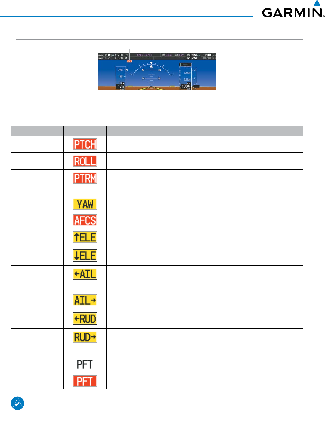
Garmin G1000 Pilot’s Guide for the Beechcraft 200/B200 Series
190-00928-04 Rev. A682
APPENDIX A
AFCS ALERTS
Figure A-8 AFCS System Status Field
System Status Field
The following alert annunciations appear in the AFCS System Status field on the PFD.
Condition Annunciation Description
Pitch Failure Pitch axis control failure. AP is inoperative.
Roll Failure Roll axis control failure. AP is inoperative.
MET Switch Stuck,
or Pitch Trim Axis
Control Failure
If annunciated when AP is engaged, take control of the aircraft and disengage the
autopilot. If annunciated when AP is not engaged, move each half of the MET
switch separately to check if a stuck switch is causing the annunciation.
Yaw Damper Failure YD control failure; AP also inoperative
System Failure AP and MET are unavailable. FD may still be available.
Elevator Mistrim Up A condition has developed causing the pitch servo to provide a sustained force. Be
prepared to apply nose up control wheel force upon autopilot disconnect.
Elevator Mistrim
Down
A condition has developed causing the pitch servo to provide a sustained force. Be
prepared to apply nose down control wheel force upon autopilot disconnect.
Aileron Mistrim Left A condition has developed causing the roll servo to provide a sustained left force.
Ensure the slip/skid indicator is centered and observe any maximum fuel imbalance
limits.
Aileron Mistrim
Right
A condition has developed causing the roll servo to provide a sustained right force.
Ensure the slip/skid indicator is centered and observe any maximum fuel imbalance limits.
Rudder Mistrim Left A condition has developed causing the yaw servo to provide a sustained force. Ensure
the slip/skid indicator is centered and observe any maximum fuel imbalance limits.
Rudder Mistrim
Right
A condition has developed causing the yaw servo to provide a sustained force.
Ensure the slip/skid indicator is centered and observe any maximum fuel imbalance
limits.
Preflight Test Performing preflight system test. Upon completion of the test, the aural alert will be
heard.
Preflight system test has failed.
NOTE: Do not press the AP/YD DISC TRIM INTRPT switch during servo power-up and preflight system tests
as this may cause the preflight system test to fail or never to start (if servos fail their power-up tests). Power
must be cycled to the servos to remedy the situation.
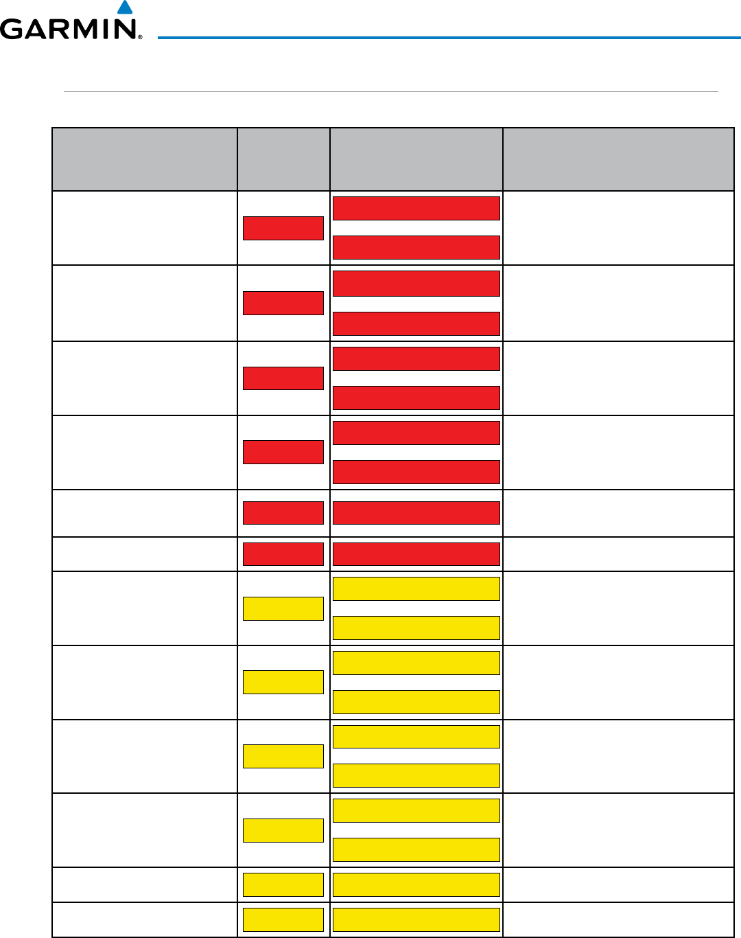
190-00928-04 Rev. A
Garmin G1000 Pilot’s Guide for the Beechcraft 200/B200 Series
683
APPENDIX A
TAWS ALERTS
Annunciations appear on both PFDs and the MFD. Pop-up alerts appear only on the MFD.
Alert Type
PFD/MFD‡
Alert
Annunciation
MFD Pop-Up Alert (except
TAWS Page)
Voice Message
Reduced Required Terrain Clearance
Warning (RTC) PULL UP
TERRAIN-PULL-UP
or
TERRAIN AHEAD-PULL-UP
“Terrain, Terrain; Pull Up, Pull Up” †
or
“Terrain Ahead, Pull Up; Terrain Ahead, Pull Up”
Imminent Terrain Impact Warning (ITI)
PULL UP
TERRAIN AHEAD-PULL-UP
or
TERRAIN-PULL-UP
Terrain Ahead, Pull Up; Terrain Ahead, Pull Up”
or
“Terrain, Terrain; Pull Up, Pull Up” †
Reduced Required Obstacle Clearance
Warning (ROC)PULL UP
OBSTACLE-PULL-UP
or
OBSTACLE AHEAD-PULL-UP
“Obstacle, Obstacle; Pull Up, Pull Up” †
or
“Obstacle Ahead, Pull Up; Obstacle Ahead, Pull Up”
Imminent Obstacle Impact Warning (IOI)
PULL UP
OBSTACLE AHEAD-PULL-UP
or
OBSTACLE-PULL-UP
“Obstacle Ahead, Pull Up; Obstacle Ahead, Pull Up”
or
“Obstacle, Obstacle; Pull Up, Pull Up” †
Excessive Descent Rate Warning (EDR) PULL UP PULL-UP “Pull Up”
or
“ [Whoop, Whoop]“Pull Up”
*Excessive Closure Rate Warning (ECR) PULL UP PULL-UP [Whoop, Whoop]“Pull Up”
Reduced Required Terrain Clearance
Caution (RTC) TERRAIN
CAUTION-TERRAIN
or
TERRAIN AHEAD
“Caution, Terrain; Caution, Terrain” †
or
“Terrain Ahead; Terrain Ahead”
Imminent Terrain Impact Caution (ITI)
TERRAIN
TERRAIN AHEAD
or
CAUTION-TERRAIN
“Terrain Ahead; Terrain Ahead”
or
“Caution, Terrain; Caution, Terrain” †
Reduced Required Obstacle Clearance
Caution (ROC) TERRAIN
CAUTION-OBSTACLE
or
OBSTACLE AHEAD
“Caution, Obstacle; Caution, Obstacle” †
or
“Obstacle Ahead; Obstacle Ahead”
Imminent Obstacle Impact Caution (IOI)
TERRAIN
OBSTACLE AHEAD
or
CAUTION-OBSTACLE
“Obstacle Ahead; Obstacle Ahead”
or
“Caution, Obstacle; Caution, Obstacle” †
Premature Descent Alert Caution (PDA) TERRAIN TOO LOW-TERRAIN “Too Low, Terrain”
Excessive Descent Rate Caution (EDR) TERRAIN SINK RATE “Sink Rate”
* TAWS-A Only
† Default Selection
‡ Annunciation is shown on the TAWS Page and the Navigation Map Page when Terrain is enabled
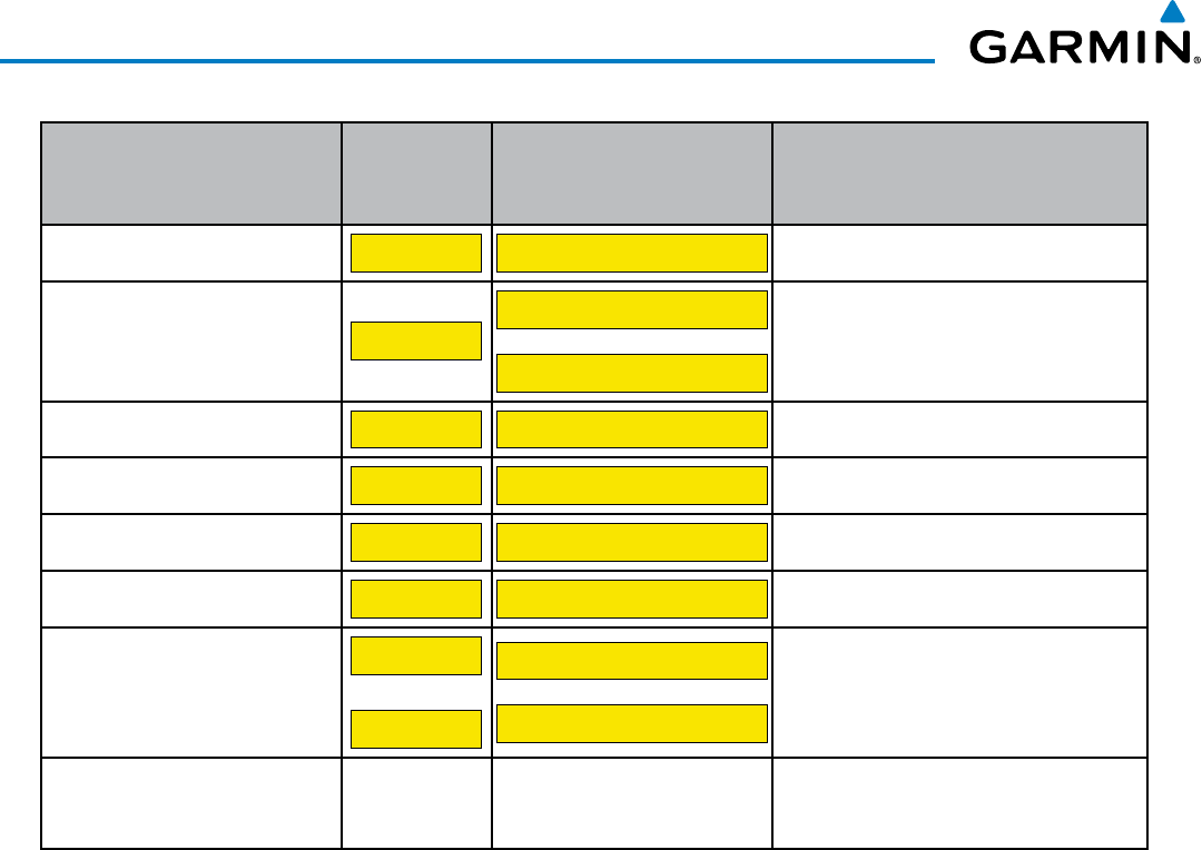
Garmin G1000 Pilot’s Guide for the Beechcraft 200/B200 Series
190-00928-04 Rev. A684
APPENDIX A
Alert Type
PFD/MFD‡
Alert
Annunciation
MFD Pop-Up Alert (except
TAWS Page)
Voice Message
*Excessive Closure Rate Caution (ECR) TERRAIN TERRAIN “Terrain, Terrain”
Negative Climb Rate Caution (NCR)
TERRAIN
DON’T SINK
or
TOO LOW-TERRAIN
“Don’t Sink” †
or
“Too Low, Terrain”
*Flight Into Terrain High Speed Caution
(FIT) TERRAIN TOO LOW-TERRAIN “Too Low, Terrain”
*Flight Into Terrain Gear Caution (FIT) TERRAIN TOO LOW-GEAR “Too Low, Gear”
*Flight Into Terrain Flaps Caution (FIT) TERRAIN TOO LOW-FLAPS “Too Low, Flaps”
*Flight Into Terrain Takeoff Caution (FIT) TERRAIN TOO LOW-TERRAIN “Too Low, Terrain”
*Glide Slope Deviation Caution (GSD)
(depends on approach type)
GLIDESLOP
or
GLIDEPATH
GLIDESLOPE
or
GLIDEPATH
“Glide Slope”
or
“Glide Path”
Altitude Voice Callout (VCO)
(all except “Five-Hundred” are
configurable)
None None “Five-Hundred” or *“Four-Hundred” or *“Three-
Hundred” or *“Two-Hundred” or *“One-Hundred”
* TAWS-A Only
† Default Selection
‡ Annunciation is shown on the TAWS Page and the Navigation Map Page when Terrain is enabled
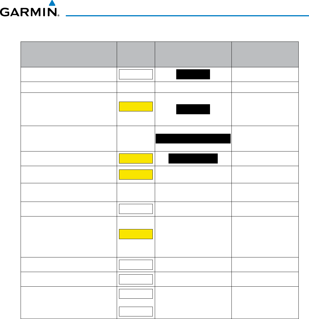
190-00928-04 Rev. A
Garmin G1000 Pilot’s Guide for the Beechcraft 200/B200 Series
685
APPENDIX A
TAWS SYSTEM STATUS ANNUNCIATIONS
Alert Type
PFD/MFD‡
Alert
Annunciation
TAWS Page Center Banner
Annunciation Voice Message
System Test in progress
TAWS TEST TAWS TEST
None
System Test pass None None “TAWS System Test OK”
TAWS System Test Fail; Terrain, Airport
Terrain or Obstacle database unavailable
or invalid on all GDUs; software mismatch
among GDUs; TAWS audio fault
TAWS FAIL
†
TAWS FAIL
“TAWS System Failure”
MFD Terrain or Obstacle database
unavailable or invalid. TAWS operating
with PFD Terrain or Obstacle databases
None
TERRAIN DATABASE FAILURE
None
No GPS position
TAWS N/A NO GPS POSITION
“TAWS Not Available”
Excessively degraded GPS signal, or out of
database coverage area
TAWS N/A
None “TAWS Not Available”
Sufficient GPS signal reception restored
None
None “TAWS Available”
(aural message only in flight)
TAWS Alerting is disabled
TAWS INH
None None
*Radar Altimeter invalid, Vertical Speed
Invalid, GPS and Baro Altitude invalid,
Software mismatch among GDUs, TAWS
configuration mismatch among GDUs,
TAWS audio fault
GPWS FAIL
†None “GPWS System Failure”
*GPWS Alerting is disabled
GPWS INH
None None
*Flap Override is enabled
FLAP OVR
None None
*Glideslope/Glidepath Alerting is disabled
GS INH
or
GP INH
None None
* TAWS-A Only
† VCO alerts are not issued if both TAWS and GPWS systems have failed or are not available.
‡ Annunciation is shown on the TAWS Page and the Navigation Map Page when Terrain is enabled.

Garmin G1000 Pilot’s Guide for the Beechcraft 200/B200 Series
190-00928-04 Rev. A686
APPENDIX A
FLIGHT PLAN IMPORT/EXPORT MESSAGES
In some circumstances, some messages may appear in conjunction with others.
Flight Plan Import/Export Results Description
‘Flight plan successfully imported.’ A flight plan file stored on the SD card was successfully imported as a stored flight plan.
‘File contained user waypoints only. User
waypoints imported successfully. No stored
flight plan data was modified.’
The file stored on the SD card did not contain a flight plan, only user waypoints. These
waypoints have been saved to the system user waypoints. No flight plans stored in the
system have been modified.
‘No flight plan files found to import.’ The SD card contains no flight plan data.
‘Flight plan import failed.’ Flight plan data was not successfully imported from the SD card.
‘Flight plan partially imported.’ Some flight plan waypoints were successfully imported from the SD card, however others
had errors and were not imported. A partial stored flight plan now exists in the system.
‘File contained user waypoints only.’ The file stored on the SD card did not contain a flight plan, only user waypoints. One or
more of these waypoints did not import successfully.
‘Too many points. Flight plan truncated.’ The flight plan on the SD card contains more waypoints than the system can support. The
flight plan was imported with as many waypoints as possible.
‘Some waypoints not loaded. Waypoints
locked.’
The flight plan on the SD card contains one or more waypoints that the system cannot find
in the navigation database. The flight plan has been imported, but must be edited within
the system before it can be activated for use.
‘User waypoint database full. Not all loaded.’ The flight plan file on the SD card contains user waypoints. The quantity of stored user
waypoints has exceeded system capacity, therefore not all the user waypoints on the SD
card have been imported. Any flight plan user waypoints that were not imported are
locked in the flight plan. The flight plan must be edited within the system before it can be
activated for use.
‘One or more user waypoints renamed.’ One or more imported user waypoints were renamed when imported due to naming
conflicts with waypoints already existing in the system.
‘Flight plan successfully exported.’ The stored flight plan was successfully exported to the SD card.
‘Flight plan export failed.’ The stored flight plan was not successfully exported to the SD card. The SD card may not
have sufficient available memory or the card may have been removed prematurely.
PILOT PROFILE IMPORT/EXPORT MESSAGES
Pilot Profile Import/Export Results Description
‘No pilot profile plan files found to
import.’
Displayed if the SD card does not have one or more valid pilot profile filenames.
‘Overwrite existing profile?’ Displayed if the profile name matches the name of existing profile.
‘Profile name invalid. Enter a different
profile name.’
Displayed if the profile name is invalid.
‘All available pilot profiles in use. Delete a
profile before importing another.’
Displayed if the maximum number for pilot profiles has been reached.
‘Pilot profile import failed.’ Displayed if the importing operation fails for any other reason.
‘Pilot profile import succeeded.’ Displayed if the importing operation succeeds.
‘Overwrite existing file?’ Displayed if the filename matches the name of an existing file on the SD card.
‘Pilot profile export failed.’ Displayed if the export operation fails.
‘Pilot profile export succeeded.’ Displayed if the export operation succeeds.
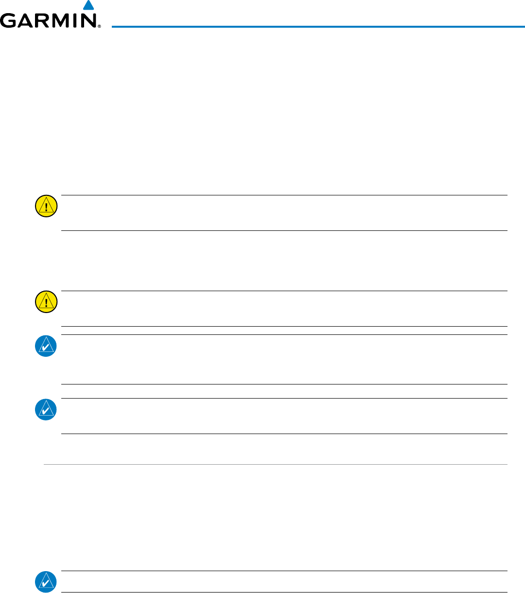
190-00928-04 Rev. A
Garmin G1000 Pilot’s Guide for the Beechcraft 200/B200 Series
687
APPENDIX B
DATABASE MANAGEMENT
Database information is obtained from third party sources. Inaccuracies in the data may be discovered from
time to time. Garmin communicates this information by issuing a Database Alert. These notifications are available
on http://fly.garmin.com.
Garmin requests the flight crew report any observed discrepancies related to database information. These
discrepancies could come in the form of an incorrect procedure; incorrectly identified terrain, obstacles and fixes;
or any other displayed item used for navigation or communication in the air or on the ground. Go to http://fly.
garmin.com and select “Aviation Data Error Report.
CAUTION: Never disconnect power to the system when loading a database. Power interuption during the
database loading process could result in maintenance being required to reboot the system.
The system uses Secure Digital (SD) cards to load and store various types of data. For basic flight operations,
SD cards are required for database storage as well as Jeppesen navigation and ChartView database updates. Not
all SD cards are compatible with the system. Use only SD cards supplied by Garmin or the aircraft manufacturer.
CAUTION: When downloading updates to the Jeppesen Navigation Database, copy the data to an SD card
other than a Garmin Supplemental Data Card. Otherwise, data corruption can occur.
NOTE: When loading database updates, the ‘DB Mismatch’ message will be displayed until database
synchronization is complete, followed by turning system power off, then on. Synchronization can be
monitored on the AUX-SYSTEM STATUS Page.
NOTE: Loading a database in the system prior to its effective date will result in the expiration date on the
power-up screen and the effective date on the AUX-System Status Page being displayed in yellow.
JEPPESEN DATABASES
The Jeppesen navigation database is updated on a 28-day cycle. The ChartView database is updated on a
14-day cycle. If the ChartView database is not updated within 70 days of the expiration date, ChartView will
no longer function. Both of these databases are provided directly from Jeppesen.
The ChartView database should be copied to the Garmin supplied Supplemental Data Card which will reside
in the bottom card slot on the MFD. The navigation database must be installed from the Jeppesen or user
supplied SD data card. Contact Jeppesen (www.jeppesen.com) for subscription and update information.
NOTE: After the navigation database is installed, the card may be removed.
Updating the active Jeppesen navigation database (not using the Dual Navigation Database or
Automatic Database Synchronization Features):
1) With the system OFF, insert the SD card containing the new navigation database version into the top card slot of the
display (PFD1, PFD2 or MFD) to be updated (label of SD card facing left).
2) Turn the system ON. A prompt similar to the following is displayed in the upper left corner of the display:
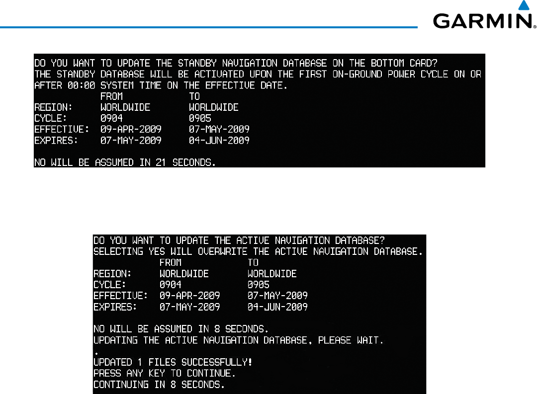
Garmin G1000 Pilot’s Guide for the Beechcraft 200/B200 Series
190-00928-04 Rev. A688
APPENDIX B
Figure B-1 Standby Navigation Database Prompt
3) Press the NO Softkey to proceed to loading the active database.
4) A prompt similar to the following is displayed, press the YES Softkey to update the active navigation database.
Figure B-2 Database Update Confirmation
5) After the update completes, the display starts in normal mode. Do not remove power while the display is
starting.
6) Turn the system OFF and remove the SD card from the top card slot.
7) Repeat steps 1 through 6 for the other displays (PFD1, PFD2 or MFD). Remove the SD card when finished.
8) Apply power to the system and press the ENT Key to acknowledge the startup screen.
9) Turn the large FMS Knob to select the AUX Page group on the MFD.
10) Turn the small FMS Knob to select the System Status Page.
11) Press the Display Database Selection Softkey to show active navigation database information for each display (MFD1
DB, PFD1 DB, PFD2 DB). Verify the correct active navigation database cycle information is shown for each display.
DUAL NAVIGATION DATABASE FEATURE
The dual navigation database feature allows each display to store an upcoming navigation database on the
bottom SD card so that the system can automatically load it to replace the active database when the new
database becomes effective (the next cycle becomes available seven days prior to its effective date).
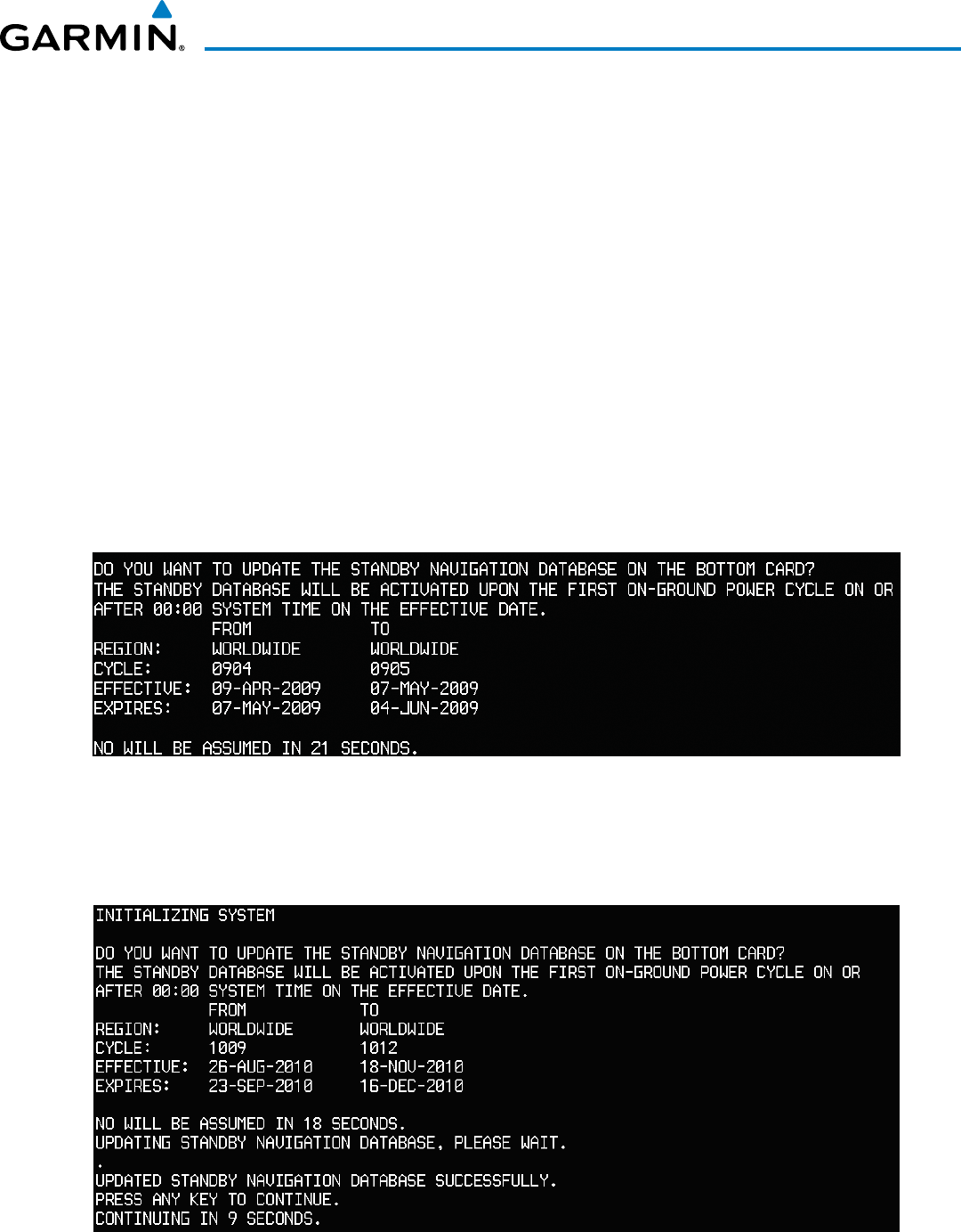
190-00928-04 Rev. A
Garmin G1000 Pilot’s Guide for the Beechcraft 200/B200 Series
689
APPENDIX B
If a navigation database loader card is inserted into the top SD card slot of a display, and an SD card is in the
bottom slot, the system will prompt the user (upon on-ground power up) as to whether the database should
be stored on the bottom SD card as the standby database. If the user responds affirmatively, the system will
copy the navigation database from the top SD card to the bottom SD card. As long as the bottom SD card
remains in the card slot, this standby navigation database will be available for the system to use as the active
database as soon as it becomes effective.
The system checks the active and standby databases upon (on-ground only) power-up. If the standby
database is current and the active database is out of date, the display will upload the standby database into the
active internal database location. Uploading the standby database to the active location takes approximately
45-55 seconds. The pilot is alerted that the update is complete by a system alert message, ‘NAV DB UPDATED’.
Loading a standby navigation database:
1) With the system OFF, insert the SD card containing the new navigation database version into the top card slot
of the MFD.
2) Verify that an SD card is inserted in the bottom slot of each PFD and the MFD.
3) Turn the system ON. A prompt similar to the following is displayed.
Figure B-3 Standby Navigation Database Prompt
4) Press the YES Softkey. The navigation database is copied to the SD card in the bottom card slot of the MFD.
5) After the navigation database files are copied to the bottom SD card, the display will appear as shown in Figure
B-4.
Figure B-4 Standby Navigation Database Update Complete
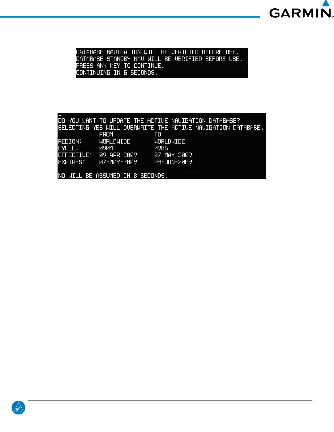
Garmin G1000 Pilot’s Guide for the Beechcraft 200/B200 Series
190-00928-04 Rev. A690
APPENDIX B
6) As instructed on the display, press any key to continue. The display will now appear as shown in Figure B-5.
Figure B-5 Navigation Database Verification Prompt
7) Press any key to continue. The display will now appear as shown in Figure B-6.
Figure B-6 Active Navigation Database Prompt
8) Press the NO Softkey. The display now starts in normal mode. Since the database effective date is not yet valid,
it should not be loaded as the active database. The display now starts in normal mode. Do not remove power
while the display is starting.
9) Press the ENT Key to acknowledge the startup screen.
10) Turn the large FMS Knob to select the AUX Page group on the MFD.
11) Turn the small FMS Knob to select the System Status Page.
12) The new database is copied to the SD card in the bottom card slot of each PFD. Progress can be monitored in
the SYNC STATUS field. When copying is finished, ‘Complete’ is displayed.
13) Turn system power OFF.
14) Remove the SD card from the top card slot of the MFD.
15) Turn system power ON.
16) Press the ENT Key to acknowledge the startup screen.
17) Turn the large FMS Knob to select the AUX Page group on the MFD.
18) Turn the small FMS Knob to select the System Status Page.
19) Press the Display Database Selection Softkey to show standby navigation database information for each display
(MFD1 DB, PFD1 DB, PFD2 DB). Verify the correct standby navigation database cycle information is shown
for each display.
NOTE: The system compares the active databases on each PFD and the MFD, and displays a system alert
message ‘DB Mismatch’ if they are not identical. Similarly, if the standby databases on each PFD and the
MFD are not identical, the system will display a ‘DB Mismatch’ alert for the standby navigation databases.
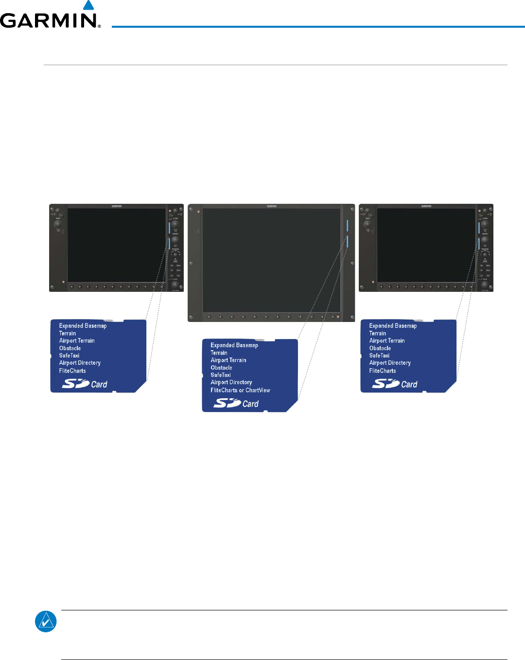
190-00928-04 Rev. A
Garmin G1000 Pilot’s Guide for the Beechcraft 200/B200 Series
691
APPENDIX B
GARMIN DATABASES
The following databases are stored on Supplemental Data Cards provided by Garmin:
• Expanded basemap
• Terrain
• Airport terrain
• Obstacle
• SafeTaxi
• FliteCharts
• Airport Directory
After subscribing to the desired database product, these database products will be downloaded to three
Supplemental Data Cards (with the exception of FliteCharts, which is loaded on only one card). Insert each
Supplemental Data Card into the correct location shown in Figure B-5. These cards must not be removed
except to update the databases stored on each card.
Figure B-7 Correct Database Locations
MFD
PFD1 PFD2
Since these databases are not stored internally in the displays, a Supplemental Data Card containing identical
database versions must be kept in each display unit.
The basemap database contains data for the topography and land features, such as rivers, lakes, and towns.
It is updated only periodically, with no set schedule. There is no expiration date.
The terrain database contains the terrain mapping data. The airport terrain database contains increased
resolution terrain data around airports. These databases are updated periodically and have no expiration date.
The obstacle database contains data for obstacles, such as towers, that pose a potential hazard to aircraft.
Obstacles 200 feet and higher are included in the obstacle database. It is very important to note that not all
obstacles are necessarily charted and therefore may not be contained in the obstacle database. This database is
updated on a 56-day cycle.
NOTE: The data contained in the terrain and obstacle databases comes from government agencies. Garmin
accurately processes and cross-validates the data, but cannot guarantee the accuracy and completeness of
the data.

Garmin G1000 Pilot’s Guide for the Beechcraft 200/B200 Series
190-00928-04 Rev. A692
APPENDIX B
The AOPA or AC-U-KWIK Airport Directory provides data on airports and heliports throughout the U.S. or
worldwide, respectively. The AOPA Directory offers detailed information for over 5,300 U. S. airports, along
with the names and phone numbers of thousands of FBOs. These databases are updated every 56 days. The
AC-U-KWIK Directory offers detailed information for more than 8,000 airports with runways longer than 3,000
feet worldwide.
The SafeTaxi database contains detailed airport diagrams for selected airports. These diagrams aid in following
ground control instructions by accurately displaying the aircraft position on the map in relation to taxiways,
ramps, runways, terminals, and services. This database is updated on a 56-day cycle.
The FliteCharts database contains procedure charts for the United States only. This database is updated on a
28-day cycle. If not updated within 180 days of the expiration date, FliteCharts will no longer function.
AUTOMATIC DATABASE SYNCHRONIZATION FEATURE
The automatic database synchronization feature automatically transfers the database from a single SD
database card to the SD cards on each PFD and the MFD to ensure that all databases are synchronized
throughout the system. After power-up, the system compares all copies of each applicable database. If similar
databases do not match, the most recent valid database is automatically copied to each card in the system that
does not already contain that database.
The following databases are checked and synchronized: Basemap, Safetaxi, Airport Terrain, Obstacle,
Airport Directory, and Terrain. This feature applies only to databases that are stored on the SD card that
resides in the bottom slot of each display. This feature does not apply to the active navigation database which
is stored internally in each display, or to the charts databases (FliteCharts and ChartView) which are only
required to be present on the MFD. The typical procedure would be to download new databases to the MFD
card, then synchronize the data to the PFD(s).
NOTE:
The 9-arc second terrain database may take as long as 100 minutes to synchronize using this method.
Therefore the user may want to transfer the data using a PC, or connect the system to a ground power
source while performing the database synchronization.
The synchronization progress may be monitored on the AUX-System Status Page in the Sync Status section
of the Database Window (Figure B-8). This section shows the synchronization status of each applicable
database, including the percent complete, time remaining, and to which displays the databases are being
copied. When the synchronization is complete, the status is listed as ‘Complete’, followed by the displays to
which the databases were copied. This sub-section is only present when a sync is occurring or has occurred
on the current power-up.
An indication of ‘Complete’ still requires a power cycle before the synchronized databases will be used by
the system.
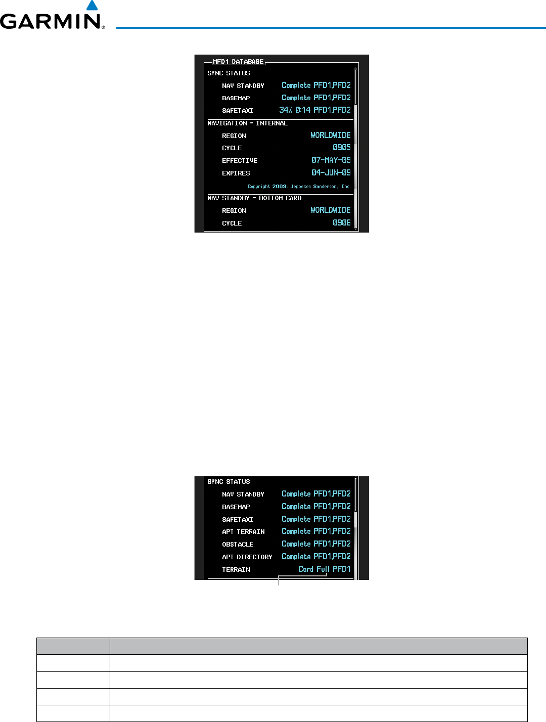
190-00928-04 Rev. A
Garmin G1000 Pilot’s Guide for the Beechcraft 200/B200 Series
693
APPENDIX B
Figure B-8 AUX-System Status Page, Database Window
The Display Database Softkey (Figure B-11) is used to place the cursor in the Database Window. Upon
first press of the Display Database Softkey, the softkey will change to a selected state (black text on gray
background) and the cursor will appear in the Database Window. At this point the user can scroll through
all databases in the Database Window to view status information. If the Display Database Softkey is pressed
repeatedly, the softkey will cycle through PFD1, PFD2, and MFD. Database status information in the Database
Window will reflect the database of the selected PFD or MFD. After a successful sync and restart, verify that
the proper databases are now in use on the AUX–System Status Page (Figure B-8).
If an error occurs during the synchronization, an error message will be displayed, followed by the affected
display in the Sync Status section of the Database Window (Figure B-9). If a synchronization completes on
one display, but an error occurs on another, the error message will be displayed with the affected diaplay
listed after it. When an error message (Table B-1) is displayed, the problem must be corrected before the
synchronization can be completed. A power cycle is required to restart synchronization when ‘Card Full’ or
‘Err’ is shown.
Figure B-9 Synchronization Error Message
Database Synchronization Error Message
Error Message Description
Canceled Database synchronization has been canceled by removing the bottom SD card in display being updated
Card Full SD card does not contain sufficient memory
Err Displayed for all other errors that may cause the synchronization process to be halted
Timeout System timed-out prior to the database transfer completing
Table B-1 Database Synchronization Error Messages

Garmin G1000 Pilot’s Guide for the Beechcraft 200/B200 Series
190-00928-04 Rev. A694
APPENDIX B
UPDATING GARMIN DATABASES
The Garmin database updates can be obtained by following the instructions detailed in the ‘Aviation
Databases’ section of the Garmin website (fly.garmin.com). Once the updated files have been downloaded
from the website, a PC equipped with an appropriate SD card reader is used to unpack and program the new
databases onto an existing Supplemental Data Card. Equipment required to perform the update is as follows:
• Windows-compatible PC computer (Windows 2000, Windows XP, Vista, or Windows 7)
• SD Card Reader: SanDisk SDDR-93, SanDisk SDDR-99, Verbatim #96504, or equivalent
• Updated database obtained from the Garmin website
• Existing Supplemental Database SD Cards (010-00330-42, or -43) from both PFDs and MFD
In some cases it may be necessary to obtain an unlock code from Garmin in order to make the database
product functional. It may also be necessary to have the system configured by a Garmin authorized service
facility in order to use some database features.
UPDATING BASEMAP, SAFETAXI, AIRPORT TERRAIN, OBSTACLE, AND AIRPORT DIRECTORY
DATABASES
These databases may be copied to one Supplemental Data Card, then automatically synchronized to other
card in the system:
1) With system power OFF, remove the MFD database card from the bottom card slot of the MFD.
2) Update the basemap, SafeTaxi, airport terrain, obstacle and/or airport directory databases on the MFD card.
3) Insert the MFD database card into the bottom card slot of the MFD.
4) Apply power to the system, check that the databases are initialized and displayed on the power-up screen
(Figure B-10). If a ‘Verifying’ message is seen, wait for the system to finish loading before proceeding to step 5.
Figure B-10 Database Information on the Power-up Screen
5) Acknowledge the Power-up Page agreement by pressing the ENT Key or the right most softkey.
6) Turn the large FMS Knob to select the AUX Page group on the MFD.
7) Turn the small FMS Knob to select the System Status Page.
8) Monitor the Sync Status in the Database Window. Wait for all databases to complete synching, indicated by
‘Complete’ being displayed as seen in Figure B-9.
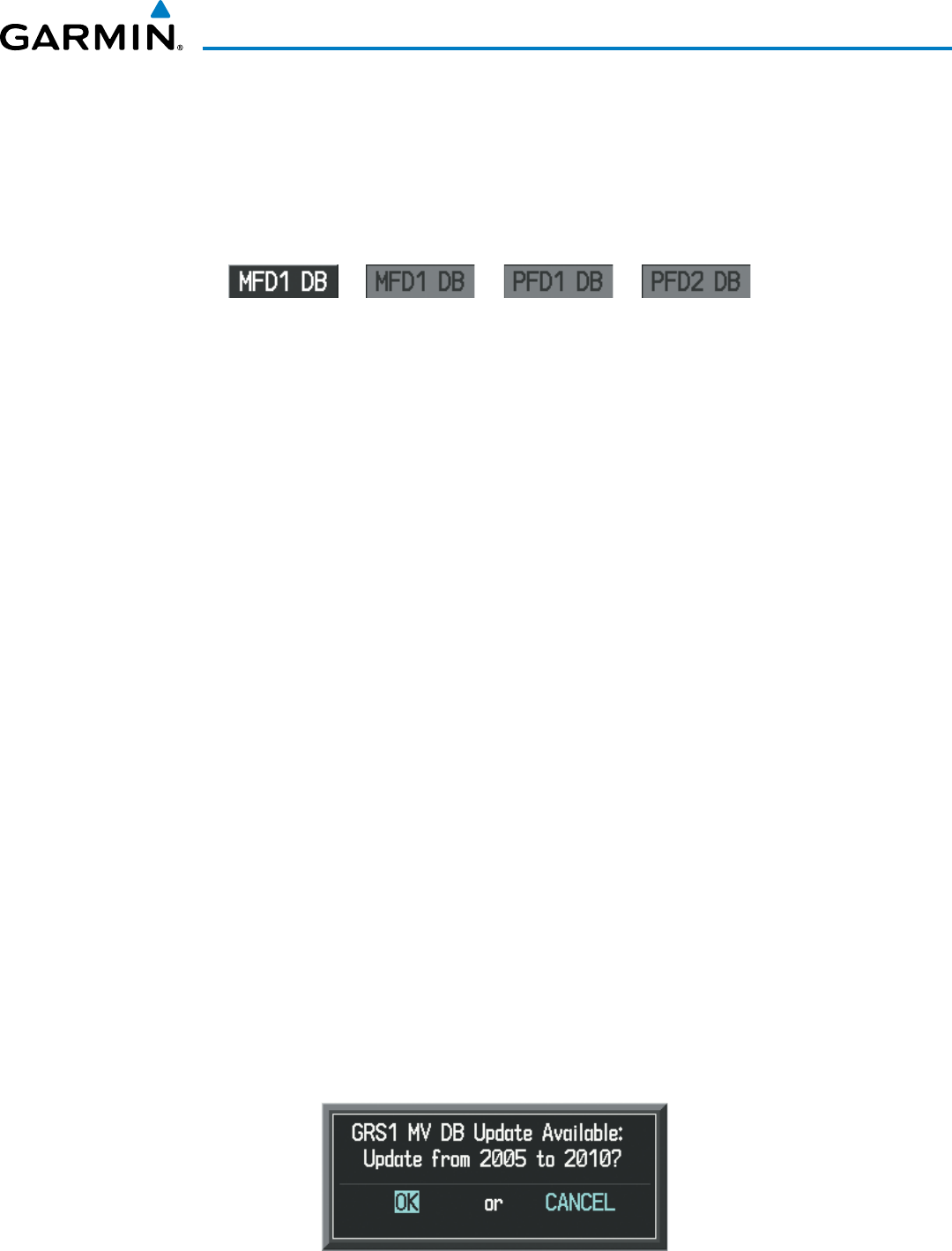
190-00928-04 Rev. A
Garmin G1000 Pilot’s Guide for the Beechcraft 200/B200 Series
695
APPENDIX B
9) Remove and reapply power to the system.
10) Turn the large FMS Knob to select the AUX Page group on the MFD.
11) Turn the small FMS Knob to select the System Status Page.
12) Press the Display Database Selection Softkey to show database information for each display (MFD1 DB, PFD1
DB, PFD2 DB). Verify the correct database cycle information is shown for each database for each display.
Figure B-11 Display Database Softkey
Unselected MFD1 DB Selected PFD1 DB Selected PFD2 DB Selected
UPDATING TERRAIN, FLITECHARTS, AND CHARTVIEW DATABASES
1) With system power OFF, remove the Supplemental Data Card from the bottom card slot of the MFD and PFDs.
2) Copy the updated terrain database to each of the Supplemental Data Cards. Copy the updated FliteCharts or
ChartView database to one Supplemental Data Card.
3) Insert the updated Supplemental Data Cards into the bottom card slot of the MFD and PFDs. The Supplemental
Data Card containing the FliteCharts or ChartView database is inserted in the MFD.
4) Apply power to the system, check that the databases are initialized and displayed on the power-up screen
(Figure B-10). A ‘Verifying’ message may be seen. If this message is present, wait for the system to finish
loading before proceeding to step 5.
5) Acknowledge the Power-up Page agreement by pressing the ENT Key or the right most softkey.
6) Turn the large FMS Knob to select the AUX Page group on the MFD.
7) Turn the small FMS Knob to select the System Status Page.
8) Press the Display Database Selection Softkey to show database information for each display (MFD1 DB, PFD1
DB, PFD2 DB). Verify the correct database cycle information is shown for each database for each display.
9) Remove power from the system.
MAGNETIC FIELD VARIATION DATABASE UPDATE
A copy of the current magnetic field variation database (MV DB) is included with the navigation database.
At startup, the system compares this version of the MV DB with that presently being used by each AHRS
(GRS1 and GRS2). If the system determines the MV DB needs to be updated, a prompt is displayed on the
Navigation Map Page, as shown in Figure B-12. Note, in the following example, GRS1 is the first AHRS to
indicate an update is available. In actuality, this is dependent on which AHRS is the first to report status to the
system. GRS2 may be displayed before GRS1. The order is not important, only that both AHRS be updated.
Figure B-12 GRS1 Magnetic Field Variation Database Update Prompt
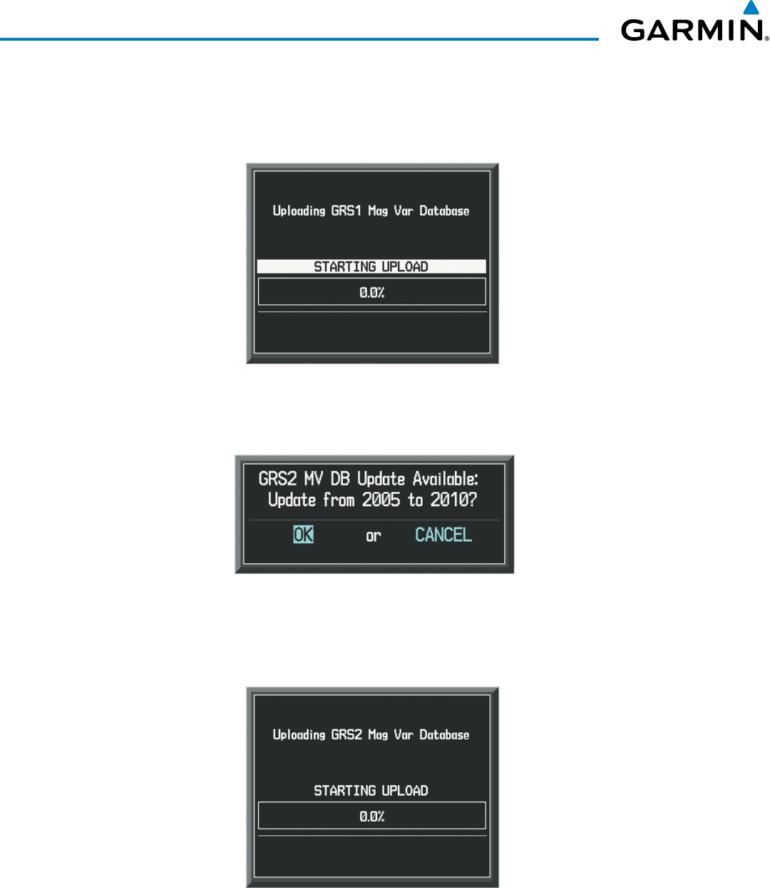
Garmin G1000 Pilot’s Guide for the Beechcraft 200/B200 Series
190-00928-04 Rev. A696
APPENDIX B
Loading the magnetic field variation database update:
1) With ‘OK’ highlighted, as seen in Figure B-12, press the ENT Key on the MFD. A progress monitor is displayed
as shown in Figure B-13.
Figure B-13 Uploading Database to GRS1
2) When the upload is complete, the prompt for the next GRS upload is displayed, as seen in Figure B-14.
Figure B-14 GRS2 Magnetic Field Variation Database Update Prompt
3) With ‘OK’ highlighted, press the ENT Key on the MFD. A progress monitor is displayed as shown in Figure B-15.
When the upload is complete, the system is ready for use.
Figure B-15 Uploading Database to GRS2

190-00928-04 Rev. A
Garmin G1000 Pilot’s Guide for the Beechcraft 200/B200 Series
697
APPENDIX C
ACC accuracy
ACT, ACTV active, activate
ADC air data computer
ADF Automatic Direction Finder
ADI Attitude Direction Indicator
AF Arc to fix
AFCS Automatic Flight Control System
AFM Airplane Flight Manual
AFMS Airplane Flight Manual Supplement
AFRM airframe
AGL Above Ground Level
AHRS Attitude and Heading Reference
System
AIM Airman’s Information Manual
AIRMET Airman’s Meteorological Information
ALRT alert
ALT altitude
ALT, ALTN alternator
AMPS amperes
ANNUNC annunciation
ANT antenna
AP autopilot
AP DISC autopilot disconnect
APR approach
APT airport, aerodrome
ARINC Aeronautical Radio Incorporated
ARSPC airspace
ARTCC Air Route Traffic Control Center
ARV arrival
AS airspeed
ASB Aviation Support Branch
ASOS Automated Surface Observing System
ATC Air Traffic Control
ATCRBS ATC Radar Beacon System
ATIS Automatic Terminal Information Service
ATK along-track
AUTOSEQ automatic sequence
AUX auxiliary
AWOS Automated Weather Observing System
B ALT barometric altitude
BARO barometric setting
BATT battery
BC backcourse
Bearing The compass direction from the
present position to a destination
waypoint.
BFO beat frequency oscillator
BKSP backspace
BRG bearing
C center runway
ºC degrees Celsius
CA Course to Altitude
CALC calculator
Calibrated
Airspeed
Indicated airspeed corrected for
installation and instrument errors.
CD Course to DME distance
CDI Course Deviation Indicator
CDU Control Display Unit
CF Course to Fix
CHT Cylinder Head Temperature
CHKLIST checklist
CHNL channel
CI Course to Intercept
CLD cloud
CLR clear
cm centimeter
CNS Communication, Navigation, &
Surveillance
CO carbon monoxide
COM communication radio
CONFIG configuration
COOL coolant
COPLT co-pilot
GLOSSARY

Garmin G1000 Pilot’s Guide for the Beechcraft 200/B200 Series
190-00928-04 Rev. A698
APPENDIX C
Course The line between two points to be
followed by the aircraft.
Course to
Steer
The recommended direction to steer
in order to reduce course error or stay
on course. Provides the most efficient
heading to get back to the desired
course and proceed along the flight
plan.
CR Course to Radial
CRG Cockpit Reference Guide
CRNT current
Crosstrack
Error
The distance the aircraft is off a
desired course in either direction, left
or right.
CRS course
CRS Course to Steer
CRSR cursor
CTA Control Area
CTRL control
Cumulative The total of all legs in a flight plan.
CVR Cockpit Voice Recorder
CVRG coverage
CWS control wheel steering
CYL cylinder
D ALT density altitude
DB, DBASE database
dBZ decibels ‘Z’ (radar return)
DCLTR,
DECLTR
declutter
DEC FUEL decrease fuel
deg degree
DEIC, DEICE de-icing
DEP departure
Desired Track The desired course between the active
“from” and “to” waypoints.
DEST destination
DF Direct to Fix
DFLT default
DGRD degrade
DH decision height
Dilution of
Precision
A measure of GPS satellite geometry
quality on a scale of one to ten (lower
numbers equal better geometry,
where higher numbers equal poorer
geometry).
DIR direction
DIS distance
Distance The ‘great circle’ distance from the
present position to a destination
waypoint.
DME Distance Measuring Equipment
DOP Dilution of Precision
DP Departure Procedure
DPRT departure
DR dead reckoning
DSBL disabled
DTK Desired Track
E empty, east
ECU Engine Control Unit
Efficiency A measure of fuel consumption,
expressed in distance per unit of fuel.
EGNOS European Geostationary Navigation
Overlay Service
EGT Exhaust Gas Temperature
EIS Engine Indication System
ELEV elevation
ELEV elevator
EMERGCY emergency
EMI Electromagnetic Interference
ENDUR endurance
Endurance Flight endurance, or total possible
flight time based on available fuel on
board.
ENG engine
ENGD engaged
ENR enroute

190-00928-04 Rev. A
Garmin G1000 Pilot’s Guide for the Beechcraft 200/B200 Series
699
APPENDIX C
Enroute Safe
Altitude
The recommended minimum altitude
within ten miles left or right of the
desired course on an active flight plan
or direct-to.
ENT enter
EPE Estimated Position Error
EPU Estimated Position Uncertainty
ERR error
ESA Enroute Safe Altitude
ESP Electronic Stability and Protection
Estimated
Position Error
A measure of horizontal GPS position
error derived by satellite geometry
conditions and other factors.
Estimated
Time of
Arrival
The estimated time at which the
aircraft should reach the destination
waypoint, based upon current speed
and track.
Estimated
Time Enroute
The estimated time it takes to reach
the destination waypoint from the
present position, based upon current
ground speed.
ETA Estimated Time of Arrival
ETE Estimated Time Enroute
EXPIRD expired
ºF degrees Fahrenheit
FA Course From Fix to Altitude
FAA Federal Aviation Administration
FADEC Full Authority Digital Engine Control
FAF Final Approach Fix
FAIL failure
FC Course From Fix to Distance
FCC Federal Communication Commission
FCST forecast
FD Course From Fix to DME Distance
FD flight director
FDE Fault Detection and Exclusion
FFLOW fuel flow
FIS-B Flight Information Services-Broadcast
FISDL Flight Information Service Data Link
FL flight level
FLC Flight Level Change
FM Course From Fix to Manual Termination
FMS Flight Management System
FOB Fuel On Board
FPL flight plan
fpm feet per minute
FREQ frequency
FRZ freezing
FSS Flight Service Station
ft foot/feet
Fuel Flow The fuel flow rate, expressed in units of
fuel per hour.
Fuel On
Board
The total amount of usable fuel on
board the aircraft.
G/S, GS glideslope
GA go-around
gal, gl gallon(s)
GBOX gearbox
GDC Garmin Air Data Computer
GDL Garmin Satellite Data Link
GDU Garmin Display Unit
GEA Garmin Engine/Airframe Unit
GEO geographic
GFC Garmin Flight Control
GFDS Garmin Flight Data Services
GIA Garmin Integrated Avionics Unit
GLS Global Navigation Satellite Landing
System
GMA Garmin Audio Panel System
GMT Greenwich Mean Time
GMU Garmin Magnetometer Unit
GND ground
gph gallons per hour
GPS Global Positioning System

Garmin G1000 Pilot’s Guide for the Beechcraft 200/B200 Series
190-00928-04 Rev. A700
APPENDIX C
Grid MORA Grid Minimum Off-Route Altitude;
one degree latitude by one degree
longitude in size and clears the highest
elevation reference point in the grid by
1000 feet for all areas of the grid
Groundspeed The velocity that the aircraft is
travelling relative to a ground position.
Ground Track see Track
GRS Garmin Reference System
GS Ground speed
GTX Garmin Transponder
HA Hold Terminating at Altitude
HDG heading
Heading The direction an aircraft is pointed,
based upon indications from a
magnetic compass or a properly set
directional gyro.
HF Hold Terminating at Fix
HFOM Horizontal Figure of Merit
Hg mercury
HI high
HI SENS High Sensitivity
HM Hold with Manual Termination
Horizontal
Figure of
Merit
A measure of the uncertainty in the
aircraft’s horizontal position.
hPa hectopascal
HPL Horizontal Protection Level
hr hour
HSDB High-Speed Data Bus
HSI Horizontal Situation Indicator
HT heat
HUL Horizontal Uncertainty Level
Hz Hertz
I Inner Marker
IAF Initial Approach Fix
IAT Indicated Air Temperature
IAU Integrated Avionics Unit
ICAO International Civil Aviation
Organization
ICS Intercom System
ID Identification/Morse Code Identifier
IDENT, IDNT identification
IF Initial Fix
IFR Instrument Flight Rules
IG Imperial gallon
ILS Instrument Landing System
IMC Instrument Meteorological Conditions
in inch
INACTV inactive
INC FUEL increase fuel
IND indicated
Indicated Information provided by properly
calibrated and set instrumentation on
the aircraft panel.
INFO information
in HG inches of mercury
INT intersection(s)
INTEG integrity (RAIM unavailable)
IrDA, IRDA Infrared Data Association
KEYSTK key stuck
kg kilogram
kHz kilohertz
km kilometer
kt knot
L left, left runway
LAT latitude
LBL label
lb pound
LCD Liquid Crystal Display
LCL local
LED Light Emitting Diode
Left Over Fuel
On Board
The amount of fuel remaining on
board after the completion of one or
more legs of a flight plan or direct-to.

190-00928-04 Rev. A
Garmin G1000 Pilot’s Guide for the Beechcraft 200/B200 Series
701
APPENDIX C
Left Over Fuel
Reserve
The amount of flight time remaining,
based on the amount of fuel on board
after the completion of one or more
legs of a flight plan or direct-to, and a
known consumption rate.
Leg The portion of a flight plan between
two waypoints.
LIFR Low Instrument Flight Rules
LNAV Lateral Navigation
LO low
LOC localizer
LOI loss of integrity (GPS)
LON longitude
LPV Localizer Performance with Vertical
guidance
LRU Line Replaceable Unit
LT left
LTNG lightning
LVL level
M Middle Marker
m meter
MAG Magnetic
MAG VAR Magnetic Variation
MAHP Missed Approach Hold Point
MAN IN manifold pressure (inches Hg)
MAN SQ Manual Squelch
MAP Missed Approach Point
MASQ Master Avionics Squelch
MAX maximum
MAXSPD maximum speed (overspeed)
MDA barometric minimum descent altitude
MET manual electric trim
METAR Meteorological Aviation Routine
MEPT manual electric pitch trim
MFD Multi Function Display
MGRS Military Grid Reference System
MHz megahertz
MIC microphone
MIN minimum
Minimum
Safe Altitude
Uses Grid MORAs to determine a safe
altitude within ten miles of the aircraft
present position.
MSAS Multi-functional Satellite
Augmentation System
MKR marker beacon
MOA Military Operations Area
MOV movement
mpm meters per minute
MSA Minimum Safe Altitude
MSG message
MSL Mean Sea Level
MT meter
mV millivolt(s)
MVFR Marginal Visual Flight Rules
N north
NAV navigation
NAVAID NAVigation AID
NDB Non-directional Beacon
NEXRAD Next Generation Radar
nm nautical mile(s)
NoPT No Procedure Turn Required
(Procdeure shall not be executed
without ATC clearance)
NRST nearest
O Outer Marker
OAT Outside Air Temperature
OBS Omni Bearing Selector
OFST offset
OXY oxygen
P ALT pressure altitude
PA Passenger Address
PA Proximity Advisory
PASS passenger(s)
PC personal computer

Garmin G1000 Pilot’s Guide for the Beechcraft 200/B200 Series
190-00928-04 Rev. A702
APPENDIX C
PFD Primary Flight Display
PI Procedure Turn to Course Intercept
PIT, PTCH pitch
POSN position
PPM parts per million
P. POS Present Position
PRES, PRESS pressure
PROC procedure(s), procedure turn
psi pounds per square inch
PT Procedure Turn
PTK parallel track
PTT Push-to-Talk
PWR power
QTY quantity
R right, right runway
RAD radial
RAIM Receiver Autonomous Integrity
Monitoring
RAM random access memory
REF reference
REM remaining (fuel remaining above
Reserve)
REQ required
RES reserve (fuel reserve entered by pilot)
REV reverse, revision, revise
RF Constant Radius Turn to Fix
RMI Radio Magnetic Indicator
RMT remote
RNG range
RNWY runway
ROL roll
ROM read only memory
rpm revolutions per minute
RST FUEL reset fuel
RSV reserve (fuel reserve entered by pilot)
RT right
RVRSNRY reversionary
RX receive
S south
SA Selective Availability
SAT Static Air Temperature
SBAS Satellite-Based Augmentation System
SCIT Storm Cell Identification and Tracking
SD Secure Digital
sec second(s)
SEL, SLCT select
SFC surface
SIAP Standard Instrument Approach
Procedures
SID Standard Instrument Departure
SIGMET Significant Meteorological Information
Sim simulator
SLP/SKD slip/skid
SMBL symbol
SPD speed
SPI Special Position Identification
SPKR speaker
SQ squelch
SRVC, SVC service
STAL stall
STAR Standard Terminal Arrival Route
STATS statistics
STBY standby
STD standard
STRMSCP Stormscope
SUA Special Use Airspace
SUSP suspend
SVS Synthetic Vision System
SW software
SYS system
T true
TA Traffic Advisory

190-00928-04 Rev. A
Garmin G1000 Pilot’s Guide for the Beechcraft 200/B200 Series
703
APPENDIX C
TACAN Tactical Air Navigation System
TAF Terminal Aerodrome Forecast
TAS True Airspeed
TAS Traffic Advisory System, true airspeed
TAT Total Air Temperature
TAWS Terrain Awareness and Warning System
TCA Terminal Control Area
TCAS Traffic Collision Avoidance System
TEL telephone
TEMP temperature
TERM terminal
TF Track Between Two Fixes
TFR Temporary Flight Restriction
T HDG True Heading
TIS Traffic Information System
TIT Turbine Inlet Temperature
TKE Track Angle Error
TMA Terminal Maneuvering Area
TMR/REF Timer/Reference
Topo topographic
Track Direction of aircraft movement relative
to a ground position; also ‘Ground
Track’
Track Angle
Error
The angle difference between the
desired track and the current track.
TRG target
TRK track
TRSA Terminal Radar Service Area
TRUNC truncated
TTL total
TURN procedure turn
TX transmit
UNAVAIL unavailable
USR user
UTC Coordinated Universal Time
UTM/UPS Universal Transverse Mercator /
Universal Polar Stereographic Grid
V, Vspeed velocity (airspeed)
VA Heading Vector to Altitude
VAPP VOR approach
VAR variation
VD Heading Vector to DME Distance
Vdc volts, direct current
VERT vertical
Vertical Figure
of Merit
A measure of the uncertainty in the
aircraft’s vertical position.
Vertical Speed
Required
The vertical speed necessary to
descend/climb from a current position
and altitude to a defined target
position and altitude, based upon
current groundspeed.
VFOM Vertical Figure of Merit
VFR Visual Flight Rules
VHF Very High Frequency
VI Heading Vector to Intercept
VLOC VOR/Localizer Receiver
VM Heading Vector to Manual Termination
VMC Visual Meteorological Conditions
VNAV, VNV vertical navigation
VOL volume
VOR VHF Omni-directional Range
VORTAC very high frequency omnidirectional
range station and tactical air
navigation
VPL Vertical Protection Level
VPROF VNV profile, vertical profile
VPTH VNV path, vertical path
VR Heading Vector to Radial
VS vertical speed
VSI Vertical Speed Indicator
VSR Vertical Speed Required
VTF vector to final
W watt(s), west
WAAS Wide Area Augmentation System

Garmin G1000 Pilot’s Guide for the Beechcraft 200/B200 Series
190-00928-04 Rev. A704
APPENDIX C
Blank Page

190-00928-04 Rev. A
Garmin G1000 Pilot’s Guide for the Beechcraft 200/B200 Series
705
APPENDIX D
FREQUENTLY ASKED QUESTIONS
If a particular aspect of G1000 operational capability is not addressed by these commonly asked questions or in
the index, contact Garmin (see the copyright page or back cover for contact information) or a Garmin-authorized
dealer. Garmin is dedicated to supporting its products and customers.
WHat iS SBaS?
The Satellite Based Augmentation System (SBAS) uses a system of ground stations to correct any GPS signal
errors. These ground stations correct for errors caused by ionospheric disturbances, timing, and satellite
orbit errors. It also provides vital integrity information regarding the health of each GPS satellite. The signal
correction is then broadcast through geostationary satellites. This correction information can then be received
by any SBAS-enabled GPS receiver.
SBAS is designed to provide the additional accuracy, availability, and integrity necessary to enable users to rely
on GPS for all phases of flight.
There are several SBAS systems serving different parts of the world. The Wide Area Augmentation System
(WAAS) is currently available in the United States, including Alaska and Hawaii. The European Geostationary
Navigation Overlay Service (EGNOS) offers coverage of Europe, parts of the middle east and northern Africa. The
Multi-functional Satellite Augmentation System (MSAS) covers mainly Japan and parts of northern Australia.
HoW DoeS SBaS aFFect aPPRoacH oPeRationS?
LP and LPV approaches use the accuracy of SBAS to provide additional precision for lateral (LP, LPV) and
vertical (LPV) guidance capability. LPV approaches also allow lower approach minimums. When SBAS is not
available, LP and LPV approaches cannot be added to the active flight plan. An LP or LPV approach already
loaded will be downgraded to an LNAV or LNAV/VNAV approach, using LNAV or LNAV/VNAV minima.
WHat iS RaiM anD HoW DoeS it aFFect aPPRoacH oPeRationS?
RAIM is an acronym for Receiver Autonomous Integrity Monitoring. RAIM is a GPS receiver function that
performs the following functions:
• Monitors and verifies integrity and geometry of tracked GPS satellites
• Notifies the pilot when satellite conditions do not provide the necessary coverage to support a certain phase
of flight
• Predicts satellite coverage of a destination area to determine whether the number of available satellites is
sufficient to satisfy requirements
NOTE
: If RAIM is not predicted to be available for the final approach course, the approach does not become
active, as indicated by the “RAIM not available from FAF to MAP” message and the LOI annunciation
flagging on the HSI.

Garmin G1000 Pilot’s Guide for the Beechcraft 200/B200 Series
190-00928-04 Rev. A706
APPENDIX D
For RAIM to work correctly, the GPS receiver must track at least five satellites. A minimum of six satellites is
required to allow RAIM to eliminate a single corrupt satellite from the navigation solution.
RAIM ensures that satellite geometry allows for a navigation solution calculation within a specified protection
limit (2.0 nm for oceanic and en route, 1.0 nm for terminal, and 0.3 nm for non-precision approaches). The
G1000 System monitors RAIM and issues an alert message when RAIM is not available (see Appendix A).
Without RAIM, GPS position accuracy cannot be monitored. If RAIM is not available when crossing the FAF,
the pilot must fly the missed approach procedure.
WHat iS gSl altituDe?
GSL (Geodetic Sea Level) altitude is the height above Mean Sea Level (MSL), as calculated geometrically,
generally using a global positioning system (GPS) as the primary data source. The calculated result may or may
not include a barometric component, but the primary source is geometric.
WHy aRe tHeRe not any aPPRoacHeS availaBle FoR a FligHt Plan?
Approaches are available for the final destination airport in a flight plan or as a direct-to (keep in mind
that some VOR/VORTAC identifiers are similar to airport identifiers). If a destination airport does not have a
published approach, the G1000 indicates “NONE” for the available procedures.
WHat HaPPenS WHen an aPPRoacH iS SelecteD? can a FligHt Plan WitH an aPPRoacH, a DePaRtuRe, oR an
aRRival Be StoReD?
When an approach, departure, or arrival is loaded into the active flight plan, a set of approach, departure,
or arrival waypoints is inserted into the flight plan, along with a header line showing the title of the selected
instrument procedure. The original en route portion of the flight plan remains active, unless the instrument
procedure is activated. This may be done either when the procedure is loaded or at a later time.
Flight plans can also be stored with an approach, a departure, or an arrival. Note that the active flight plan
is erased when the system is turned off. Also, the active flight plan is overwritten when another flight plan is
activated. When storing flight plans with an approach, a departure, or an arrival, the G1000 uses the waypoint
information from the current database to define the waypoints. If the database is changed or updated, the
G1000 System automatically updates the information, provided the procedure has not been modified. Should
an approach, departure, or arrival procedure no longer be available, the flight plan becomes locked until the
procedure is deleted from the flight plan.
can “Slant golF” (“/g”) Be FileD uSing tHe g1000?
“/G” may be filed for a flight plan. The G1000 system meets the requirements of TSO-C145a Class 3 or
TSO-C145c Class 3, and ETSO C145 Class 3 installations. GPS approaches are not to be flown with an
expired database. See the approved AFM/POH as well as the Aeronautical Information Manual (AIM) for more
information.
WHat DoeS tHe oBS SoFtkey Do?
The OBS Softkey is used to select manual sequencing of waypoints. Activating OBS mode sets the current
active-to waypoint as the primary navigation reference and prevents the system from sequencing to the next
waypoint in a flight plan. When OBS mode is cancelled, automatic waypoint sequencing is continued, and
the G1000 automatically activates the next waypoint in the flight plan once the aircraft has crossed the present
active waypoint.

190-00928-04 Rev. A
Garmin G1000 Pilot’s Guide for the Beechcraft 200/B200 Series
707
APPENDIX D
Normal (OBS not activated) OBS
• Automatic sequencing of waypoints • Manual sequencing - ‘holds’ on selected waypoint
• Manual course change on HSI not possible • Manually select course to waypoint from HSI
• Always navigates ‘TO’ the active waypoint • Indicates ‘TO’ or ‘FROM’ waypoint
• Must be in this mode for final approach course • Cannot be set for final approach course or published holding patterns
When OBS mode is active, the G1000 allows the pilot to set a desired course to/from a waypoint using the
CRS/BARO
Knob
and HSI (much like a VOR).
The most common application for using the OBS Softkey is the missed approach. The G1000 suspends
automatic waypoint sequencing (indicated by a ‘SUSP’ annunciation placed on the HSI) when the missed
approach point (MAP) is crossed. This prevents the G1000 from automatically sequencing to the missed
approach holding point (MAHP). During this time, the
OBS
Softkey designation changes to
SUSP
. Pressing
the
SUSP
Softkey reactivates automatic waypoint sequencing. The
OBS
Softkey then resumes its normal
functionality.
WHy DoeS tHe g1000 not autoMatically Sequence to tHe neXt WayPoint?
The G1000 only sequences flight plan waypoints when automatic sequencing is enabled (i.e., no “OBS” or
‘SUSP’ annunciation). For automatic sequencing to occur, the aircraft must also cross the “bisector” of the turn
being navigated. The bisector is a line passing through the waypoint common to two flight plan legs at an
equal angle from each leg.
HoW can a WayPoint Be SkiPPeD in an aPPRoacH, a DePaRtuRe, oR an aRRival?
The G1000 allows the pilot to manually select any approach, departure, or arrival leg as the active leg of
the flight plan. This procedure is performed on the MFD from the Active Flight Plan Page by highlighting the
desired waypoint and selecting the ACT LEG Softkey then the ENT Key to approve the selection. The GPS
then provides navigation along the selected flight plan leg.
WHen DoeS tuRn anticiPation Begin?
The G1000 smooths adjacent leg transitions based on a normal 15° bank angle (with the ability to roll up to
30°) and provides three pilot cues for turn anticipation:
• A waypoint alert (‘Next DTK ###° in # seconds’ or ‘Next HDG ###° in # seconds’) appears on the PFD 10
seconds before the turn point and flashes as it counts down to zero.
• A flashing turn advisory (‘Turn [right/left] to ###° in # seconds’) appears on the PFD 10 seconds before the
turn and flashes as it counts down to zero. ‘Turn [right/left] to ###° now’ or ‘Next [DTK/HDG] to ###° now’
is displayed when the pilot is to begin the turn and the HSI (GPS mode) automatically sequences to the next
DTK or HDG value.
• The To/From indicator on the HSI flips momentarily to indicate that the midpoint of the turn has been
crossed.
Garmin G1000 Pilot’s Guide for the Beechcraft 200/B200 Series
190-00928-04 Rev. A708
APPENDIX D
WHen DoeS tHe cDi Scale cHange?
Once a departure is activated, the G1000 Course Deviation Indicator (CDI) full scale deflection is set to 0.3
nm. The CDI scale changes to 1.0 nm (terminal mode) then ramps up to 2.0 nm (enroute mode) at 30 nm
from the departure airport. When 31 nm from the destination, the CDI scale smoothly transition from 2.0 nm
back to 1.0 nm (terminal mode). At 2.0 nm before the FAF during an active approach, the CDI scale transitions
down further based on the type of approach activated (LNAV, LNAV/VNAV, LP, LPV). When a missed approach
is activated, the CDI is set to 0.3 nm. See the Flight Instruments Section for more details on CDI scaling.
WHy DoeS tHe HSi not ReSPonD like a voR WHen oBS MoDe iS active?
Unlike a VOR, the CDI scale used on GPS equipment is based on the crosstrack distance to the desired
course, not on the angular relationship to the destination. Therefore, the CDI deflection on the GPS is constant
regardless of the distance to the destination and does not become less sensitive when further away from the
destination.
WHat iS tHe coRRect MiSSeD aPPRoacH PRoceDuRe? HoW iS tHe MiSSeD aPPRoacH HolDing Point SelecteD?
To comply with TSO specifications, the G1000 does not automatically sequence past the MAP. The first
waypoint in the missed approach procedure becomes the active waypoint when the SUSP Softkey is selected
after crossing the MAP. All published missed approach procedures must be followed, as indicated on the
approach plate.
To execute the missed approach procedure prior to the MAP (not recommended), select the Active Flight Plan
Page and use the ACT LEG Softkey to activate the missed approach portion of the procedure.
aFteR a MiSSeD aPPRoacH, HoW can tHe SaMe aPPRoacH Be Re-SelecteD? HoW can a neW aPPRoacH Be
activateD?
NOTE
: Do not attempt to reactivate the current approach prior to crossing the missed approach point
(MAP). If an attempt to do so is made, an alert message “Are you sure you want to discontinue the current
approach?” appears. The G1000 directs the pilot back to the transition waypoint and does not take into
consideration any missed approach procedures, if the current approach is reactivated.
After flying the missed approach procedure, the pilot may reactivate the same approach for another attempt by
pressing the
PROC
Key. Once the clearance is given for another attempt, activate the approach by highlighting
‘ACTIVATE APPROACH’ using the large
FMS
Knob and pressing the
ENT
Key. The G1000 provides navigation
along the desired course to the waypoint and rejoins the approach in sequence from that point.
To activate a new approach for the same airport, select the new procedure by pressing the
PROC
Key. Choose
‘SELECT APPROACH’, select the desired approach from the list shown, and press the
ENT
Key. Select the
desired transition, then activate the approach using the
ENT
Key.
To activate a new approach to a different airport, press the Direct-to Key and select the desired airport using
the FMS Knobs. Press the ENT Key to accept the selected airport, then follow the steps in the preceding
paragraph to select an approach for the new airport.
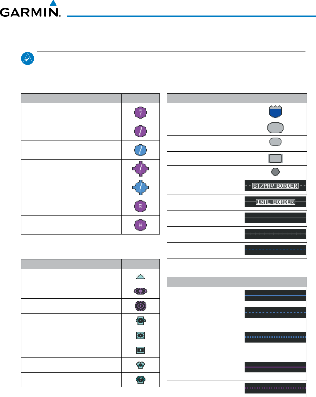
190-00928-04 Rev. A
Garmin G1000 Pilot’s Guide for the Beechcraft 200/B200 Series
709
APPENDIX E
AIRPORT
Item Symbol
Unknown Airport
Non-towered, Non-serviced Airport
Towered, Non-serviced Airport
Non-towered, Serviced Airport
Towered, Serviced Airport
Restricted (Private) Airport
Heliport
NAVAIDS
Item Symbol
Intersection
LOM (compass locator at outer marker)
NDB (non-directional radio beacon)
VOR
VOR/DME
VOR/ILS
VORTAC
TACAN
LINE SYMBOLS
Item Symbol
Interstate Highway
State Highway
US Highway
National Highway
City
State or Province Border
International Border
Road
Railroad
Latitude/Longitude
AIRSPACE BOUNDARIES
Item Symbol
ICAO Control Area
Class B Airspace
Mode C Tower Area
Warning Area
Alert Area
Caution Area
Danger Area
Prohibited Area
Restricted Area
Training Area
Unknown Area
Class C
Terminal Radar Service Area
Mode C Area
Military Operations Area (MOA)
MAP SYMBOLS
NOTE
: Refer to the Flight Management Section for the topography legend and the Hazard Avoidance
Section for XM Weather Product legends.
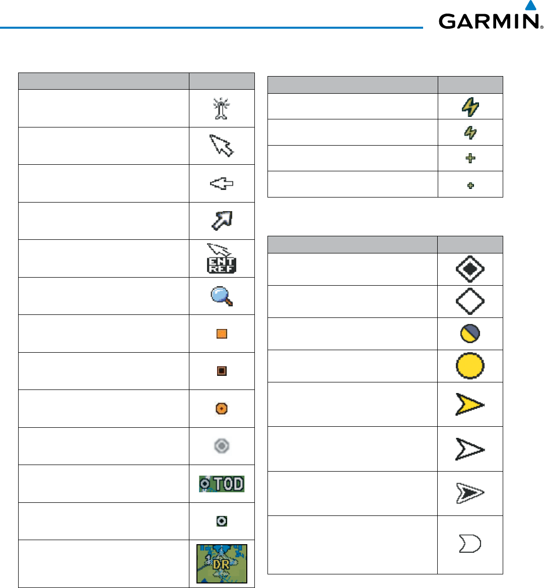
Garmin G1000 Pilot’s Guide for the Beechcraft 200/B200 Series
190-00928-04 Rev. A710
APPENDIX E
MISCELLANEOUS
Item Symbol
ARTCC Frequency or FSS Frequency
Default Map Pointer
Elevation Pointer
Wind Vector
Measuring Pointer
Overzoom Indicator
User Waypoint
Vertical Navigation Along Track Waypoint
Parallel Track Waypoint
Unanchored Flight Path Waypoint
Top of Descent (TOD)
Bottom of Descent (BOD)
Navigating using Dead Reckoning
STORMSCOPE LIGHTNING STRIKES
Item Symbol
Lightning Strike (0-6 sec ago)
Lightning Strike (6-20 sec ago)
Lightning Strike (20-60 sec ago)
Lightning Strike (60-120 sec ago)
TRAFFIC
Item Symbol
Non-threat Traffic (hollow diamond)
Proximity Advisory
Traffic Advisory, Out of Range
Traffic Advisory
Traffic Advisory (TA) arrow with ADS-B
directional information. Points in the
direction of the intruder aircraft track.
Proximity Advisory (PA) arrow with ADS-B
directional information. Points in the
direction of the aircraft track .
Non-threat traffic arrow with ADS-B
directional information. Points in the
direction of the intruder aircraft track .
PA or Non-threat traffic arrow with ADS-B
directional information, but positional
accuracy is degraded. Points in the
direction of the aircraft track
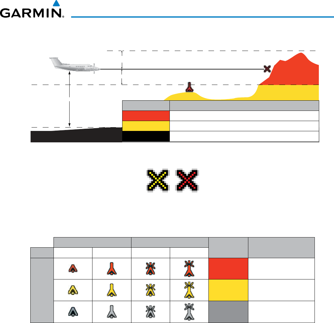
190-00928-04 Rev. A
Garmin G1000 Pilot’s Guide for the Beechcraft 200/B200 Series
711
APPENDIX E
TERRAIN AVOIDANCE COLORS AND SYMBOLS
Potential Impact Point
Unlighted Obstacle
Projected Flight Path
1000 ft
100 ft Threshold
Terrain Above Aircraft Altitude
Terrain Color Terrain Location
Red (WARNING) Terrain above, or within 100 ft below the aircraft altitude
Yellow (CAUTION) Terrain between 100 ft and 1000 ft below the aircraft altitude
Black
Terrain more than 1000 ft below the aircraft altitude
Figure E-1 TAWS Color Chart
Figure E-2 TAWS Potential Impact Points
Unlighted Obstacle Lighted Obstacle Obstacle
Color Obstacle Location
Height < 1000 ft AGL > 1000 ft AGL < 1000 ft AGL > 1000 ft AGL
Obstacle Symbol
Red
(WARNING)
Obstacle within 100 ft of
or above aircraft altitude
Yellow
(CAUTION)
Obstacle within 1000 ft of
aircraft altitude
Gray Obstacle more than 1000
ft below aircraft altitude
Obstacle Symbols and Colors
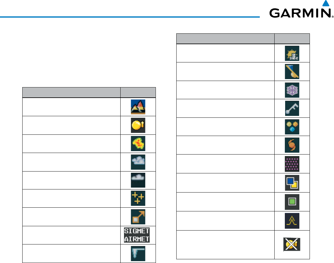
Garmin G1000 Pilot’s Guide for the Beechcraft 200/B200 Series
190-00928-04 Rev. A712
APPENDIX E
HAZARD AVOIDANCE FEATURES
This table identifies the symbols displayed in the
lower right corner of PFD or MFD maps to indicate
which hazard avoidance features are activated for
display.
Feature Symbol
TAWS display enabled
Traffic display enabled
Data Link Weather Radar display
enabled
Cloud Top display enabled
Echo Top display enabled
Lightning display enabled
Cell Movement display enabled
SIGMETs/AIRMETs display enabled
METARs display enabled
Feature Symbol
City Forecast display enabled
Surface Analysis display enabled
Freezing Levels display enabled
Winds Aloft display enabled
County Warnings display enabled
Cyclone Warnings display enabled
Icing Potential (CIP and SLD) (ICNG)
Pilot Weather Report (PIREPs)
Air Report (AIREPs)
Turbulence (TURB)
Loss of hazard avoidance feature, (a
white X is shown over the symbol to
indicate not available; e.g., traffic)

190-00928-04 Rev. A
Garmin G1000 Pilot’s Guide for the Beechcraft 200/B200 Series
I-1
INDEX
A
Activate a Flight Plan --------------------------------------231
Active database ------------------------------------- 688, 689
Active frequency ------------------------------------ 112, 122
AC-U-KWIK ------------------------------------ 547, 606, 692
ADF audio --------------------------------------------------- 123
ADS-B --------------------------------------------------------445
AFCS Status Box -------------------------------------- 56, 494
AHRS -------------------------------------------- 675, 676, 677
Aircraft Symbol ---------------------------------------------496
Air Data Computer -------------------------------------1, 664
Airport
Information ----------------------------------------------188
Airport Directory ------------------------547, 606, 607, 692
Airspace Alerts -------------------------------- 204, 205, 309
Airspeed Indicator ---------------------------------56, 58–59
Airspeed Reference ---------------------------490, 504–505
Airways
Collapsed ------------------------------------------------- 244
Expanded ------------------------------------------------- 244
Alerting System ------------------------------------- 659, 664
Audio------------------------------------------------------660
Alerts --------------------------------------------------------659
AFCS ------------------------------------------------------682
Aircraft ----------------------------------------------------661
Arrival ------------------------------------------------------ 46
Audio voice ----------------------------------------------- 46
Levels -----------------------------------------------------660
TAWS ------------------------------------------------------683
Alerts Window ----------------------------------------------- 84
Along Track Offset -----------------------------------------236
ALT -----------------------------------------------------------305
Altimeter --------------------------------------------56, 63–64
Altimeter barometric setting ------------------------------ 56
Altitude
Constraints ---------------------------------------- 252, 292
Altitude alerting --------------------------------------------- 87
Altitude Hold Mode ---------------------------------------502
Altitude Reference ---------------------------- 501, 502, 510
Annunciations
Comparator ----------------------------------------------663
G1000 System -------------------------------------- 20, 664
Reversionary Sensor ------------------------------------664
Test tone --------------------------------------------- 47, 660
Annunciations, softkey ------------------------------------- 84
Annunciation Window ------------------------------------- 84
Annunciator lights -----------------------------------------142
AOPA ------------------------------------------- 547, 606, 692
AOPA Airport Directory ----------------------- 607, 608, 609
AP ------------------------------------------------------------682
Approach ---------------------------------------------------- 706
Activating ------------------------------------------------265
ILS ---------------------------------------------------------538
Loading -------------------------------------- 228, 262, 265
Missed ----------------------------------------------------542
Removing -------------------------------------------------266
WAAS -----------------------------------------------------540
Approach channel ---------------------------------- 228, 262
Approach Mode ------------------------------- 520, 538, 540
APR softkey ------------------------------------------ 265, 272
Arc HSI -------------------------------------------------------- 69
Arrival procedure -----212, 226, 259, 261, 289, 292, 301
Attitude --------------------------------------------------------- 1
Attitude & Heading Reference System ------------------664
Attitude Indicator ----------------------------------56, 61–62
Audio Panel Fail-Safe Operation ------------------------- 150
Automatic Dependent Surveilence - Broadcast -------445
Automatic Flight Control System (AFCS) -------- 489–546
Alerts and annunciations ----------------------- 544–545
Controls ------------------------------------------- 490–491
Status Annunciations -----------------------------------544
Status Box ------------------------------------------------494
Automatic squelch ----------------------------------------- 121
Autopilot -------------------------------- 489, 524–526, 682
Autopilot Disconnect ------------------------------- 491, 526
Auto-tuning ------------------------------------------------- 130
Auto-tuning, COM ----------------------------------------- 116
Auto-tuning, NAV ------------------------------------------126
Auto Zoom -------------------------------------------------- 156
Auxiliary Pages (AUX) -------------------------------------- 36
AUX - system status page 564, 566, 586, 587, 603, 605,
608
Aviation Symbols ------------------------------------ 168, 212
B
Backcourse Mode ------------------------------------------ 522
Backlighting ------------------------------------------------- 53
Barometric setting, Altimeter ---------------------56, 64–65
Basic Empty Weight ---------------------------------------273
Basic Operating Weight ----------------------------------- 273
Bearing/distance, measuring -----------------------------163
Bearing information ----------------------------------- 71–72
Bearing Information Windows ---------------------------- 57
Bearing line ------------------------------------ 387, 390, 391
Bearing source ---------------------------------------------- 72
C
Calibrated Airspeed ----------------------------------------270
Cargo --------------------------------------------------------274
CDI --------------------------- 261, 280, 292, 300, 307, 679
Chart Not Available --------------------------------- 569, 590
Chart options ---------------------------------------- 577, 597
CHART SETUP box ---------------------------------- 583, 600
ChartView --------------------------------547, 567, 568, 586
CLD TOP Softkey -------------------------------------------363
Clearance Recorder ----------------------------------------145
Closest Point ------------------------------------------------245
COM channel spacing ------------------------------------- 120

Garmin G1000 Pilot’s Guide for the Beechcraft 200/B200 Series
190-00928-04 Rev. AI-2
INDEX
COM Frequency Box --------------------------------------- 112
Command Bars --------------------------------------------- 496
Communication (COM) Frequency Box ------------------ 56
Comparator Annunciations -------------------------------663
Comparator Window --------------------------------------- 85
COM Tuning Failure ----------------------------------------148
Controls (Softkeys) ------------------------------------- 20–23
Control Wheel Steering (CWS) -------------------- 491, 525
Copy a Flight Plan -----------------------------------------231
Course Deviation Indicator (CDI) -------------------- 73–76
Course To Altitude -----------------------------------------268
Cylinder Head Temperature (CHT °F) -------------------- 96
D
Database(s) -------------------------------------------- 14, 687
Database Synchronization ------------------- 687, 692, 693
Data link-------------------------------------------------------- 1
Data Link Receiver -----------------------------------------658
Datalink receiver troubleshooting -----------------------657
Data logging ------------------------------------------------ 649
Date and time ----------------------------------------------- 39
Day/Night views ------------------------------------- 583, 600
Day view --------------------------------------------- 584, 601
DB Mismatch -----------------------------------------------690
Dead Reckoning --------------------------------------------- 92
Decision Height (DH) -----------------------------------57, 88
Declutter, display -------------------------------------------- 94
Delete Flight Plans ----------------------------------------- 231
Deleting
An entire airway ---------------------------------- 233, 234
An entire procedure ----------------------------- 233, 234
An individual waypoint -------------------------- 232, 233
Flight Plan Items ----------------------------------------232
Density Altitude --------------------------------------------271
Departure
Procedure -----------------------------224, 238, 256, 258
Select -----------------------------------256, 259, 262, 266
Time -------------------------------------------------------269
Timer ------------------------------------------------------- 50
Digital audio entertainment --------------------------------- 2
Dilution of Precision (DOP) -------------------------------- 31
Direct-to - 181, 206, 207, 208, 209, 210, 211, 250, 251,
290, 292, 307
Display backup ---------------------------------------- 16, 109
DME audio --------------------------------------------------123
DME Information Window --------------------------------- 72
DME tuning -------------------------------------------------132
Dual navigation database --------------------------------688
E
Electronic Stability ---------------------------------- 547, 650
Electronic Stability and Protection (ESP) --- 61, 547, 650,
651, 652, 653, 654
Emergency frequency --------------------------------------148
Engine Indication System (EIS) ----------------------95–104
Entering Flight ID ------------------------------------------133
Estimated Landing Fuel -----------------------------------275
Estimated Position Error (EPE) ---------------------------- 31
Excess Fuel Weight ----------------------------------------275
Excessive Descent Rate Alert ---------------------- 409, 426
Extended squitter ------------------------------------------445
F
Failure
Input ---------------------------------------------------18, 19
FD ------------------------------------------------------------682
Field of View (SVS) ----------------------------------------- 179
Flight Director (FD) ---------------------------489, 493–494
Modes, lateral ------------------------------------ 515–546
Modes, vertical ----------------------------------- 499–513
Switching ------------------------------------------ 492, 495
Flight Level Change Mode ------------------- 504, 532, 536
Flight plan
Closest point to reference -----------------------------245
Storing ----------------------------------------------------706
Flight plan Import/Export Messages --------------------686
Flight timer --------------------------------------------------- 50
FliteCharts ------------------------------------------- 547, 588
FliteCharts cycle -------------------------------------------- 603
FliteCharts expiration -------------------------------------603
FliteCharts functions --------------------------------------589
FPA ---------------------------------------------------- 252, 297
Frequency
Nearest ---------------------------------------------------201
Frequency spacing -----------------------------------------120
Frequently asked questions -------------------------------705
Fuel
Efficiency -------------------------------------------------271
Endurance ------------------------------------------------271
Remaining ------------------------------------------------ 271
Required --------------------------------------------------271
Statistics --------------------------------------------------271
Fuel Flow (FFLOW GPH) ----------------------------------- 96
Fuel on Board --------------------------------- 271, 274, 275
Fuel Quantity (FUEL QTY GAL) ---------------------------- 96
G
Gain ---------------------------------------------------------- 390
Garmin Connext--------------------------------------------547
Garmin Databases -----------------------------------------691
GBT ----------------------------------------------------------446
GDC 74A ------------------------------------------------------- 1
GDL 69/69A --------------------------------------------------- 1
GDU 1040 ----------------------------------------------------- 1
GEA 71 --------------------------------------------------------- 1
Geodetic sea level -----------------------------------------401

190-00928-04 Rev. A
Garmin G1000 Pilot’s Guide for the Beechcraft 200/B200 Series
I-3
INDEX
GFC 700 -----------------------------------------------------489
GIA 63 ---------------------------------------------------------- 1
Glidepath ----------------------------------------------------305
Glidepath Indicator ----------------------------------------- 66
Glidepath Mode (GP) ------------------------- 511, 520, 540
Glideslope --------------------------------------------------- 305
Glideslope Indicator ---------------------------------------- 66
Glideslope Mode ------------------------------------ 512, 538
Global Positioning System (GPS)
Navigation ---------------------------------------- 206–310
Receiver information -------------------------------- 30–32
GMA 1347 ------------------------------------------------ 1, 14
GMU 44 -------------------------------------------------------- 1
Go Around Mode -----------------------------513, 542–543
GPS Window ------------------------------------------------ 693
GRA 5500 Message Advisories --------------------------678
Ground-Based Transceivers ------------------------------- 446
Ground mapping ------------------------------------------- 394
Groundspeed ------------------------------------------------ 51
GRS 77 --------------------------------------------------------- 1
GSD 41 Message Advisories -----------------------------674
GSL ----------------------------------------------------------- 401
GTS 800 -----------------------------------------------------678
GTX 33 ES---------------------------------------------------445
GTX 33 Mode S Transponders ------------------------1, 133
H
Hazard Avoidance features ------------------------------- 712
Heading ------------------------------------------------------ 56
Heading Preset Mode -------------------------------------- 18
Heading Select Mode -------------------------------------517
HI SENS ------------------------------------------------------ 131
Horizontal scan ------------- 386, 387, 388, 389, 392, 393
Horizontal Situation Indicator (HSI) ----------- 68–80, 262
HSI double green arrow -----------------------------------122
HSI magenta arrow ----------------------------------------122
HSI single green arrow ------------------------------------ 122
I
IDENT function ---------------------------------------------135
ID indicator -------------------------------------------------125
ILS approach ------------------------------------------------ 538
Indicated Altitude ------------------------------------------270
Initialization (system) --------------------------------------- 14
Inset Map, PFD ---------------------------------------------- 57
Intercom ----------------------------------------------------- 143
Intersection
Information --------------------------------------- 189–190
Inverting a flight plan -------------------------------------231
IOI ----------------------------------------------- 408, 423, 683
Iridium satellite network -- 609, 611, 616, 620, 622, 624
ISA ------------------------------------------------------------ 81
J
Jeppesen navigation database ---------------------------687
K
Key(s) --------------------------------------------------------6, 8
L
Land Symbols ----------------------------------------------- 167
Lateral modes, flight director ---------------------- 515–546
Level Mode -------------------------------------------------650
LNAV --------------------------------------------------------- 280
LO SENS -----------------------------------------------------131
Low Altitude Annunciation -------------------------------- 88
Low speed data ------------------------------------- 609, 610
LPV ---------------------------------------------- 280, 307, 527
M
Magnetometer ------------------------------------------- 1, 18
Map
Pages ------------------------------------------------------- 35
Panning --------------------------------------------------- 158
Symbols --------------------------------------------------- 709
Marker Beacon ---------------------------------------------131
Marker Beacon Annunciations ---------------------------- 86
MASQ processing ------------------------------------------105
Measurement units, changing displayed ---------------- 45
Menus -------------------------------------------------------- 34
Message Advisories ----------------------------------------660
Database -------------------------------------------------668
G1000 System -------------------------------------------667
GCU 477 -------------------------------------------------677
GDC 74B -------------------------------------------------676
GDL 59----------------------------------------------------678
GDL 69A --------------------------------------------------676
GEA 71 ---------------------------------------------------674
GIA 63W -------------------------------------------------671
GMA 1347D ---------------------------------------------670
GMC 710 ------------------------------------------------- 677
GMU 44 --------------------------------------------------676
GRS 77 ----------------------------------------------------675
GSR 56 ----------------------------------------------------678
GTS 820/850 --------------------------------------------678
GTX 33----------------------------------------------------674
GWX 68 --------------------------------------------------677
MFD & PFD -----------------------------------------------667
Miscellaneous -------------------------------------------679
Message Advisory Alerts ----------------------------------661
Messages
Reminder -------------------------------------------------- 51
MET ----------------------------------------------------------682
Minimum Descent Altitude (MDA) -------------------57, 88

Garmin G1000 Pilot’s Guide for the Beechcraft 200/B200 Series
190-00928-04 Rev. AI-4
INDEX
Minimums --------------------------------------------------- 662
MISCOMP ---------------------------------------------------663
Missed Approach----------- 212, 266, 276, 280, 307, 542
Mistrim ------------------------------------------------------682
MKR/MUTE -------------------------------------------------131
Mode S ----------------------------------------- 133, 138, 139
Mode selection softkeys -------- 133, 134, 135, 136, 137
Mode S Transponder
TCAS II Transponder Controls -------------------------136
TCAS II Transponder Mode Selection -----------------137
Morse code identifier --------------------------------------125
Multi Function Display (MFD)
Softkeys ---------------------------------------------------- 28
N
National Weather Service --------------------------------- 340
NAV1 audio ------------------------------------------------- 123
NAV2 audio ------------------------------------------------- 123
Navigation
Database ------------------------------------------ 252, 253
Map -------------------------------------------------------209
Navigation Mode ---------------------- 518–519, 530–531
Navigation mode selection -------------------------------122
Navigation (NAV) Frequency Box ------------------------- 56
Navigation source ------------------------------------- 73–75
Navigation Status Box ------------------------------------- 56
Nav radio selection ----------------------------------------122
Nearest
Airport ------------- 185, 186, 187, 188, 201–204, 265
Airport Minimum Runway Length --------------------188
Airports Page ------------------------------- 186, 187, 188
Airport Surface Matching ------------------------------188
VOR ------------------------------------------------ 201–202
Nearest airports, frequency tuning ----------------------116
Nearest Pages (NRST) -------------------------------------- 37
NEXRAD Softkey -------------------------------------------360
Night view ------------------------------------------- 584, 602
NO COMP --------------------------------------------------- 663
Non-path descent -----------------------------509, 536–537
Normal operating mode ----------------------------------- 15
O
OAT ----------------------------------------------------------- 81
OBS Mode----------------------------------------------- 79–80
Obstacles --------------------------------------------- 670, 671
Odometer ---------------------------------------------------- 51
Oil Pressure (OIL PSI) --------------------------------------- 96
Omni Bearing Selector (OBS) ---------------------- 706–707
Other Statistics -------------------------------------- 269, 271
Outside Air Temperature ----------------------------------- 81
Outside Air Temperature (OAT) --------------------------- 56
Overview ------------------------------------------------------- 1
P
Page groups -------------------------------------------- 35–38
Parallel Track ----------------------------------------- 237, 238
Passenger Address (PA) System --------------------------144
Passenger(s) ------------------------------------------------274
PFD failure --------------------------------------------------149
Pilot and Stores Weight -----------------------------------273
Pilot Profile Import/Export Messages -------------------686
Pilot profiles -------------------------------------------- 41–42
PIREP --------------------------------------------------------371
Pitch Hold Mode -------------------------------------------500
Pitch indication ---------------------------------------------- 61
Power ON settings ----------------------------------------- 142
Predefined message -------------------------- 629, 630, 632
Primary Flight Display (PFD)
Softkeys ----------------------------------------------- 20–22
Procedures
GFC 700 ------------------------------------------- 527–543
Q
Quick tuning 121.500 MHz ------------------------------115
R
RA ------------------------------------------------------------475
Radar altitude ----------------------------------------------- 90
Radar Signal Attenuation ---------------------------------379
Radar Signal Reflectivity ----------------------------------379
Radar, Weather ---------------------------------------------377
RAIM ------------------------------- 261, 276, 277, 278, 279
Range -------------------------------------------------------- 177
Receiver Autonomous Integrity Monitoring (RAIM) 31–32,
276, 705
Reminder messages ---------------------------------------- 51
Required
Vertical Speed -------------------------------------------298
Vertical Speed Indicator -------------------------------- 298
Reversionary Mode ----------------------------------------150
Reversionary Sensor Annunciations ---------------------664
Reversionary Sensor Window ----------------------------- 85
ROC --------------------------------------------- 408, 423, 683
Roll Hold Mode---------------------------------------------516
RS-232 ---------------------------------------------------------- 2
RS-485 ---------------------------------------------------------- 2
RVSI --------------------------------------------------- 298, 299
RX indicator -------------------------------------------------113
S
SafeTaxi ----------------------------------------- 547, 561, 564
SafeTaxi database ------------------------------------------565
SBAS --------------------------------------276, 278, 279, 705
Scheduler ----------------------------- 51–52, 547–548, 646

190-00928-04 Rev. A
Garmin G1000 Pilot’s Guide for the Beechcraft 200/B200 Series
I-5
INDEX
Sector scan ------------------------------------------- 390, 391
Secure Digital (SD) card ------------------------------ 13, 687
Selected Altitude 56, 63, 87, 500, 501, 503, 504, 506, 510
Selected Altitude Bug -------------------------------------- 56
Selected Altitude Capture Mode 500, 501, 502, 503, 506
Selected Altitude Intercept Arc ---------------------------180
Selected Course ----------------------57, 69, 519, 521, 522
Selected Heading -------------------------------69, 490, 517
Selecting a COM radio ------------------------------------112
Sensor ------------------------------------------------ 663, 664
Sequencing, automatic ------------------------------------707
Sequencing waypoints, suspend -------------------------- 80
Servos, AFCS ------------------------------------------------489
SIGMET ----------------------------------------------- 330, 365
Simultaneous COM Operation ---------------------------144
SiriusXM
Radio ------------------------------------------------------ 312
SiriusXM radio volume ------------------------------------645
SiriusXM Weather
PIREPs-----------------------------------------------------344
Skywatch ----------------------------------------------------458
Slip/Skid Indicator ---------------------------------------56, 61
SMS ----------------------------------------------------------547
Softkey annunciations -------------------------------------- 84
Softkeys-------------------------------------------------- 20–27
MFD -------------------------------------------------------- 28
PFD --------------------------------------------------------- 21
Speaker ------------------------------------------------------142
STAB ---------------------------------------------------------392
Standby database ------------------------------------------ 689
Standby frequency ---------------------------- 112, 116, 122
Standby frequency field -----------------------------------112
Standby Navigation Database -------------------- 689, 690
Stereo headsets --------------------------------------------142
Stormscope WX-500 Series II ----------------------------395
Stuck microphone ------------------------------------------148
Sunrise ------------------------------------------------------- 270
Sunset -------------------------------------------------------270
Surface Analysis --------------------------------------------334
SVS troubleshooting --------------------------------------- 655
Symbols, map ----------------------------------------------- 709
Synthetic vision (SVS) ------------------------ 547, 548, 680
System annunciations --------------------------20, 659, 665
System Setup Page ----------------------------------------- 38
System Status Page ----------------------------------------- 47
System time -------------------------------------------------- 56
T
TA ----------------------------------------------------- 475, 662
Tachometer (RPM) ------------------------------------------ 96
TAF ---------------------------------------------- 332, 366, 367
Takeoff Mode ----------------------------------------------- 513
TAS --------------------------- 386, 388, 389, 390, 391, 675
TAS Traffic
Non-Threat Traffic -------------------------- 437, 446, 458
PA--------------------------------------------------- 446, 458
Proximity Advisory-------------------------------- 446, 458
TAWS -------------------------------- 87, 413, 423, 434, 436
TAWS-B ------------------------------------------------------ 418
TAWS System Status Annunciations --------------------685
TCAS II Traffic
Operation -------------------------------------------------481
System Status -------------------------------------------- 487
System Test -----------------------------------------------480
TCAS II Alerts --------------------------------------------475
TCAS System Test Fail -------------------------------------662
TCAS System Test Passed ---------------------------------662
Telephone -----------------------------3, 547, 609, 611, 612
Terminal procedures charts ------------------------ 569, 590
Terrain ------------------------------------423, 670, 683, 684
Color indications ----------------------------------------711
Terrain Awareness and Warning System ----------------418
Text message ----------------------------624, 626, 629, 632
Text messaging ---------------------------------------------624
Tilt ----------------------------------------------------- 388, 389
Tilt line -------------------------------------------------------389
Timer
Departure -------------------------------------------------- 50
Flight ------------------------------------------------------- 50
Timer, PFD generic ------------------------------------------ 48
TIS ------------------------------------------------------------437
TOD --------------------------------------------- 297, 298, 304
TOPO DATA ------------------------------------ 164, 165, 174
Top of Descent -------------------------------------- 297, 298
TOPO SCALE ------------------------------------------------166
Track ---------------------------------------------------------- 68
Traffic Advisory (TA)-----------------------------86, 386, 662
Traffic Annunciation ---------------------------------------- 57
Traffic Information Service (TIS)
Voice alerts ------------------------------------------------ 86
Transponder ----------------------------------------------23, 24
Transponder code entry -----------------------------------139
Transponder data box -------------------------------------105
Transponder mode field --------- 105, 135, 136, 138, 139
Transponder standby mode ----------------------- 135, 138
Transponder Status Box ------------------------------------ 56
Trend Vector
Turn Rate -------------------------------------------------- 71
Trip Planning ----------------------------------- 269, 270, 271
Trip statistics -------------------------------------51, 270, 271
True Airspeed ------------------------------------- 56, 58, 271
Turn anticipation -------------------------------------------707
Turn Rate Indicator ----------------------------------------- 71
TX indicator ------------------------------------------------- 113

Garmin G1000 Pilot’s Guide for the Beechcraft 200/B200 Series
190-00928-04 Rev. AI-6
INDEX
U
Unable to display chart ---------------------------- 569, 590
Unmuted Inputs -------------------------------------------- 142
Updating Garmin databases -----------------------------565
User-Defined Holding Pattern ---------------------------- 247
V
Vertical deviation ------------------------------------- 64, 508
Vertical deviation guidance ------------------------------253
Vertical Deviation Indicator (VDI) -------------66, 298, 299
Vertical navigation ----------------------------------------- 252
Direct-to ------------------------------------------- 251, 252
Vertical Navigation flight control ----------------- 506–510
Vertical Path Tracking Mode -----------------506–507, 534
Vertical scan ----------------------------------------- 388, 389
Vertical speed guidance-----------------------------------253
Vertical Speed Indicator (VSI) ----------------------------- 66
Vertical Speed Mode --------------------------------------503
Vertical Speed Reference ---------------------------------503
Vertical track ------------------------------------------------662
VFR code ----------------------------------------------------141
VNAV ------------------------------------------------- 211, 680
VNAV Target Altitude ------------------------------- 506–509
VNAV Target Altitude Capture Mode -------------------510
VNV --------------------------------------------------- 297, 703
VNV guidance
Disabling -------------------------------------------------251
Enabling --------------------------------------------------250
VNV indications, PFD --------------------------------------- 83
VOICE Alerts ------------------------------------------------662
Voice alerts, TIS Traffic ------------------- 86, 441, 464, 472
Volume ------------------------------------------------------645
VOR
Nearest -------------------------------------------- 201–202
VOR selection -----------------------------------------------122
VSI ------------------------------------------------------------299
Vspeed references ------------------------------------------ 57
Vspeeds ------------------------------------------------- 59–60
VS TGT ------------------------------------------------ 252, 297
W
WAAS -------------------------------------280, 527, 671, 705
WAAS precision approach --------------------------------540
WATCH ----------------------------------------------- 392, 393
Waypoint
Automatic sequencing ---------------------------------707
Skipping --------------------------------------------------707
Waypoint Selection Submenu ---------207, 215, 219, 277
Weather Attenuated Color Highlight -------------------392
Weather (real-time) ------------------------------------------- 2
Weather Softkeys ------------------------------------------318
Wi-Fi --------------------------------------547, 609, 636, 640
Wind -------------------------------------------------- 154, 176
Wind data ---------------------------------------------------- 57
Winds Aloft -------------------------------------------------368
WIND Softkey -----------------------------------------------368
X
XM radio --------------------------------------------- 641, 643
XM radio active channel ----------------------------------643
XM radio channel list --------------------------------------643
XM radio presets ------------------------------------------- 644
XM radio service class -------------------------------------642
XM Satellite Weather
AIREPs ----------------------------------------------------344
AIRMETs ------------------------------------------- 330, 365
Cell Movement ------------------------------------------329
Cloud Tops -----------------------------------------------327
County Warnings ----------------------------------------340
Cyclones & Hurricanes ---------------------------------341
Echo Tops -------------------------------------------------326
Freezing Level --------------------------------------------336
Icing -------------------------------------------------------342
Lightning -------------------------------------------------328
SIGMETs ------------------------------------------- 330, 365
Surface Analysis -----------------------------------------334
Turbulence ------------------------------------------------343
Winds Aloft -----------------------------------------------337
XPDR softkey -----------------------------------------------137
Z
Zoom
Auto ------------------------------------------------------- 156

Garmin International, Inc.
1200 East 151st Street
Olathe, KS 66062, U.S.A.
p:913.397.8200
f:913.397.8282
www.garmin.com
Garmin AT, Inc.
2345 Turner Road SE
Salem, OR 97302, U.S.A.
p:503.391.3411
f:503.364.2138
Garmin (Europe) Ltd.
Liberty House, Hounsdown Business Park
Southampton, Hampshire SO40 9LR U.K.
p:44 (0) 23 8052 4000
f:44 (0) 23 8052 4004
Aviation Support:44 (0) 87 0850 1243
Garmin Corporation
No. 68, Jangshu 2nd Road
Shijr, Taipei County, Taiwan
p:886/02.2642.9199
f:886/02.2642.9099
