Garmin Sounder 125 Users Manual Man Rev B
393-M-Gps-125-Sounder-Manual-Owner-S-Manual 393-m-gps-125-sounder-manual-owner-s-manual
SOUNDER 125 GPS125Sounder_OwnersManual
125 to the manual 6693f7ba-24e0-4deb-970f-0627ccb1e5c4
2015-01-29
: Garmin Garmin-Sounder-125-Users-Manual-216855 garmin-sounder-125-users-manual-216855 garmin pdf
Open the PDF directly: View PDF ![]() .
.
Page Count: 84
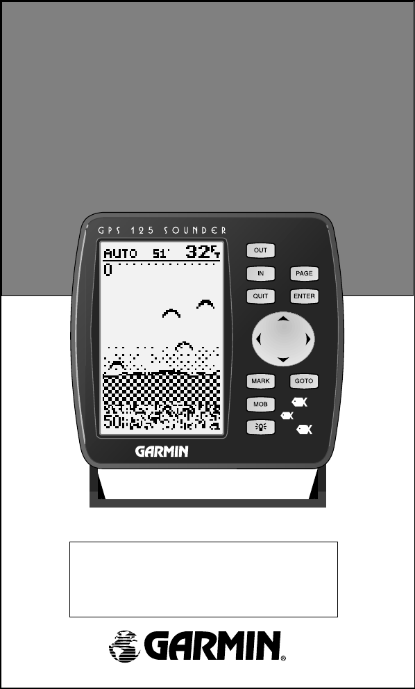
GPS 125
Sounder
Marine
Navigator
ZOOM
Owner’s Manual
&
Reference
125 Man Rev B 7/23/98 11:47 AM Page i
Software Version 2.0 or above
© 1997 GARMIN Corporation
1200 E. 151st Street, Olathe, KS USA 66062
Tel: 913-397-8200 or 800-800-1020
Fax: 913-397-8282
Web Site Address: www.garmin.com
GARMIN (Europe) Ltd.
Unit 5, The Quadrangle, Abbey Park, Romsey, SO51 9AQ, U.K.
Tel: 011-44-1794-519944
Fax: 011-44-1794-519222
GARMIN (Taiwan) Corp.
4th Fl., No. 1., Lane 45,
Pao-Hsing Road,
Hsin Tien, Taiwan R.O.C.
Phone: 886.02.917.3773
Fax: 886.02.917.1758
All rights reserved. No part of this manual may be reproduced or transmitted in any
form or by any means, electronic or manual, including photocopying and recording, for
any purpose without the express written permission of GARMIN.
Information in this document is subject to change without notice. GARMIN reserves
the right to change or improve its products and to make changes in the content without
obligation to notify any person or organization of such changes or improvements.
GARMIN, AutoLocate, and TracBack are all trademarks of GARMIN Corporation
and may not be used without the expressed permission of GARMIN.
July 1997 Part #190-00111-00 Rev. B Printed in Taiwan.
125 Man Rev B 7/23/98 11:47 AM Page ii

i
INTRODUCTION
Overview
GPS 125
SOUNDER
Operator’s
Manual
Welcome to the easiest-to-use combination GPS/Depth Sounder on the
water! The GPS 125 Sounder represents GARMIN’s continuing commitment to
provide mariners with quality navigation and fishfinding information in a versa-
tile, accurate, and user-friendly design which will be useful for years to come. It
is important that you take the time to read through the operator’s manual to
understand the operating features of the GPS 125 Sounder. The manual is orga-
nized into four sections for your convenience:
Introduction gives a quick overview of the manual and contains the table
of contents and glossary of navigation terms.
Getting Started takes you through step-by-step instructions to initialize the
receiver for first-time use and introduces you to the basic features of the unit
with a quick-start orientation to the GPS 125 Sounder. This section has been
designed to acquaint you with the unit and provide a basic working knowledge
necessary to use the unit in typical conditions.
Reference provides detailed explanations of the advanced features and oper-
ations of the GPS 125 Sounder in a topical format. This allows you to concen-
trate on a specific topic quickly, without reading through entire sections of text
that you may not need.
The Appendix section contains installation instructions and items with mul-
tiple listings, such as: map datums, time offsets, and the index.
See your GARMIN dealer for accessories including our PC kit and standard
or temperature reading in-hull and transom-mount transducers.
Thanks for choosing the GARMIN GPS 125 Sounder. We hope it will help
you meet all of your navigation and fishfinding needs.
125 Man Rev B 7/23/98 11:47 AM Page iii

Caution
INTRODUCTION
ii
The GPS system is operated by the government of the United States,
which is solely responsible for its accuracy and maintenance. The system is
subject to changes which could affect the accuracy and performance of all
GPS equipment. Although the GPS 125 Sounder is a precision electronic
NAVigation AID (NAVAID), any NAVAID can be misused or misinterpreted
and, therefore, become unsafe.
Use the GPS 125 Sounder at your own risk. To reduce the risk of
unsafe operation, carefully review and understand all aspects of this
Operator’s Manual and thoroughly practice operation using the simulator
mode prior to actual use. When in actual use, carefully compare indications
from the GPS 125 Sounder to all available navigation sources including the
information from other NAVAIDs, visual sightings, maps, etc. For safety,
always resolve any discrepancies before continuing navigation.
NOTE: This device meets requirements for Part 15 of the FCC limits for
Class B digital devices for home or office use. It has been tested for compli-
ance with all necessary FCC standards. This equipment generates, uses, and
can radiate radio frequency energy and, if not installed and used in accor-
dance with the instructions, may cause harmful interference to radio commu-
nications. However, there is no guarantee that interference will not occur in a
particular installation. If this equipment does cause harmful interference to
other equipment, which can be determined by turning the equipment off and
on, the user is encouraged to try and correct the interference by relocating the
equipment or connecting the equipment to a different circuit than the affected
equipment. Consult an authorized dealer or other qualified service technician
for additional help if these remedies do not correct the problem. Operation is
subject to the following conditions: (1) This device cannot cause harmful
interference, and (2) this device must accept any interference received,
including interference that may cause undesired operation. The GPS 125
Sounder does not contain any user-serviceable parts. Repairs should only be
made by an authorized service center. Unauthorized repairs or modifications
could void your warranty and your authority to operate this device under Part
15 regulations.
125 Man Rev B 7/23/98 11:47 AM Page iv

1
INTRODUCTION
Table of
Contents
SECTION ONE Introduction
Glossary/Navigation Basics . . . . . . . . . . . . . . . . . . . . . . . . . . . . . . . .2-4
SECTION TWO Getting Started
Turning On and Initializing the Receiver . . . . . . . . . . . . . . . . . . . . . .5-7
Primary Page Overview . . . . . . . . . . . . . . . . . . . . . . . . . . . . . . . . . .8-9
Marking a Waypoint . . . . . . . . . . . . . . . . . . . . . . . . . . . . . . . . . . . . .10
Position Page and Map Basics . . . . . . . . . . . . . . . . . . . . . . . . . . . .11-12
Going to A Waypoint . . . . . . . . . . . . . . . . . . . . . . . . . . . . . . . . . . . . .12
Using the Highway Page and Cancelling a GOTO . . . . . . . . . . . . .13-14
Using The Sounder Page . . . . . . . . . . . . . . . . . . . . . . . . . . . . . . . .14-17
Clearing a Map and Turning Off . . . . . . . . . . . . . . . . . . . . . . . . . . . . .17
SECTION THREE Reference
Satellite Page . . . . . . . . . . . . . . . . . . . . . . . . . . . . . . . . . . . . . . . .17-19
Position Page . . . . . . . . . . . . . . . . . . . . . . . . . . . . . . . . . . . . . . . . . . .20
Marking, Saving, and Using Waypoints . . . . . . . . . . . . . . . . . . . . .21-28
TracBack Navigation . . . . . . . . . . . . . . . . . . . . . . . . . . . . . . . . . . .29-30
Creating and Using Routes . . . . . . . . . . . . . . . . . . . . . . . . . . . . . .31-36
Sounder Page . . . . . . . . . . . . . . . . . . . . . . . . . . . . . . . . . . . . . . . .37-40
Map Plotting, Zooming, and Cursor Movement . . . . . . . . . . . . . . .41-43
Using the Compass and Highway Navigation Pages . . . . . . . . . . . .44-46
Menu Page and Distance/Sun Calculation . . . . . . . . . . . . . . . . . . . . . .47
Track Log Setup . . . . . . . . . . . . . . . . . . . . . . . . . . . . . . . . . . . . . .47-48
Interface Setup and DGPS Interface . . . . . . . . . . . . . . . . . . . . . . . .49-51
System Setup . . . . . . . . . . . . . . . . . . . . . . . . . . . . . . . . . . . . . . . .51-52
Navigation Setup . . . . . . . . . . . . . . . . . . . . . . . . . . . . . . . . . . . . .53-55
Map Page Setup . . . . . . . . . . . . . . . . . . . . . . . . . . . . . . . . . . . . . .55-56
Alarms Setup . . . . . . . . . . . . . . . . . . . . . . . . . . . . . . . . . . . . . . . . . .57
Sounder Setup . . . . . . . . . . . . . . . . . . . . . . . . . . . . . . . . . . . . . . .58-61
Navigation Simulator . . . . . . . . . . . . . . . . . . . . . . . . . . . . . . . . . .62-63
Appendix A––Installation . . . . . . . . . . . . . . . . . . . . . . . . . . . . . . .64-69
Appendix B—Wiring and Specifications . . . . . . . . . . . . . . . . . . . .70-71
Appendix C—Messages and Time Offsets . . . . . . . . . . . . . . . . . . .72-73
Appendix D—Map Datums . . . . . . . . . . . . . . . . . . . . . . . . . . . . .74-76
Appendix E––Index . . . . . . . . . . . . . . . . . . . . . . . . . . . . . . . . . . .77-78
125 Man Rev B 7/23/98 11:47 AM Page 1

Glossary
INTRODUCTION
2
The GPS 125 Sounder is a powerful navigation tool that can guide you any-
where in the world. To better understand its operation and capabilities, it may be
helpful to review the basic terms and concepts briefly explained below.
Other navigation and GPS definitions used in the manual are defined in the
appropriate reference sections of the manual.
Almanac Data
Satellite constellation information (including location and health of satellites) that is
transmitted to your receiver from every GPS satellite. Almanac data must be acquired
before GPS navigation can begin.
Bearing (BRG)
The compass direction from your position to a destination.
Course Made Good (CMG)
The bearing from the “active from” position (your starting point) to your present
position.
Crosstrack Error (XTE)
The distance you are off a desired course in either direction.
Desired Track (DTK)
The compass course between the “from” and “to” waypoints.
Differential GPS (DGPS)
An extension of the GPS system that uses land-based radio beacons to transmit position
corrections to GPS receivers.
Estimated Time of Arrival (ETA)
The time of day of your arrival at a destination.
Estimated Time Enroute (ETE)
The time left to your destination at your present speed.
Ground Speed (SOG)
The velocity you are traveling relative to a ground position.
125 Man Rev B 7/23/98 11:47 AM Page 2

3
INTRODUCTION
Glossary
Latitude
The north/south measurement of position perpendicular to the earth’s polar axis.
Longitude
An east/west measurement of position in relation to the Prime Meridian, an imagi-
nary circle that passes through the north and south poles.
Position
An exact, unique location based on a geographic coordinate system.
Sensitivity
A measure of how sensitive the sounder is to sonar echoes.
Speed Over Water (SOW)
The speed you are traveling over the surface of the water.
Thermocline
A layer of water separating warmer water above from cooler water below.
Track (TRK)
The direction of movement relative to a ground position.
Universal Transverse Mercator (UTM)
A grid coordinate system that projects global sections onto a flat surface to measure
position in specific zones.
Velocity Made Good (VMG)
The speed you are traveling in the direction of your destination.
Waypoint
A specific location saved in the receiver’s memory.
Whiteline
A term applied to the checkered portion of the sonar display which shows the area
of strongest sonar return (typically the bottom).
125 Man Rev B 7/23/98 11:47 AM Page 3
Navigation
Basics
INTRODUCTION
4
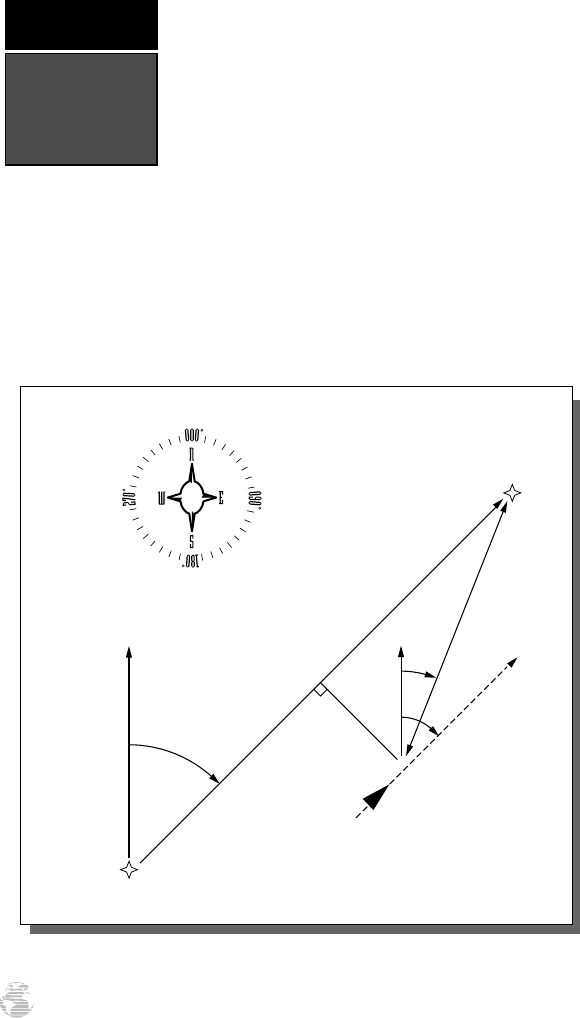
NORTH
“ACTIVE FROM”
WAYPOINT
NORTH
DTK
CROSSTRACK ERROR
BRG
TRK
GROUND SPEED
DISTANCE
“ACTIVE TO”
WAYPOINT
“ACTIVE LEG”
The GPS 125 Sounder provides steering guidance and
navigation information using degrees, a measurement mea-
sured in a clockwise direction from a north reference. North
is described as 000º, east as 090º, south as 180º, and west as
270º. The diagram and compass rose below provide a graphic
illustration of the navigation terms used by the GPS 125
Sounder. More information on basic navigation and GPS are
available at your local library or bookstore.
125 Man Rev B 7/23/98 11:47 AM Page 4
Getting Started with Your GPS
Welcome to the exciting world of GARMIN GPS!
The GPS 125 Sounder represents GARMIN’s continuing
commitment to provide marine users with quality navi-
gation information in a versatile, user-friendly design
they will enjoy for years to come. To get the most out
of your GPS receiver, be sure to read through the ini-
tialization and Getting Started sections of this manual,
and refer to the reference section for complete details
on the GPS 125 Sounder’s advanced features.
Initializing Your GPS for First-Time Use
The first time you power up your new GPS 125
Sounder is an important step in getting the best possi-
ble future GPS performance.
Because a GPS receiver can only receive signals
from satellites above the horizon, it needs to know
what satellites to look for at any given time. By using
an almanac (a timetable of satellite numbers and their
orbits) stored in the receiver’s memory, the GPS 125
Sounder can determine the distance and position of
any GPS satellite and then use this information to
determine your position.
To obtain this almanac data, your GPS receiver
needs to be initialized or given the opportunity to “find
itself”, the very first time it is turned on. Once you
have initialized the unit, the GPS 125 Sounder will
compute future fixes more rapidly, usually in a few
minutes.
Remember, that initializing the unit is only neces-
sary under the following conditions:
• First-time use from the factory
• If the receiver has been moved over 500 miles
from the last calculated position with power
off
• If the receiver’s memory has been cleared and
all stored data has been lost
5
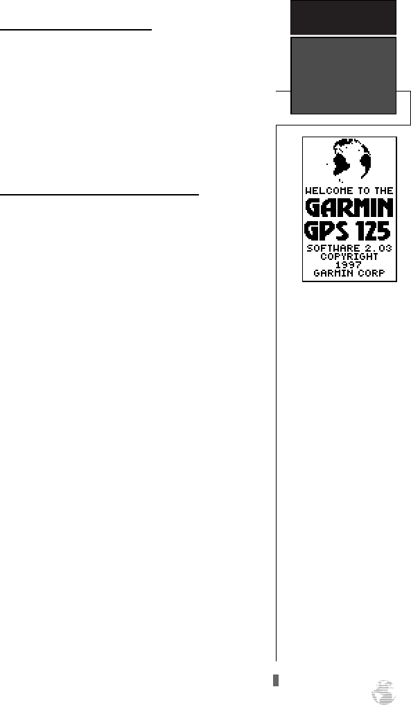
Welcome Page
The welcome page will
appear as soon as the GPS
125 Sounder is turned on
and remain on while the
unit conducts a brief
self-test.
GETTING
STARTED
Initialization
125 Man Rev B 7/23/98 11:47 AM Page 5
Initializing the Receiver
The receiver is shipped from the factory in
AutoLocate™ mode, which enables the GPS 125
Sounder to determine its location anywhere in the
world. To speed up the initialization process, we recom-
mend using EZinit described below, which will usually
provide a fix in a few minutes.
Before you initialize, make sure your GPS 125
Sounder unit, antenna, and transducer have been cor-
rectly installed on your boat according to the instruc-
tions in Appendix A.
To turn the GPS 125 Sounder on:
1. Press and hold
P
until the receiver turns on.
The welcome page will be displayed while the unit
conducts a self test.
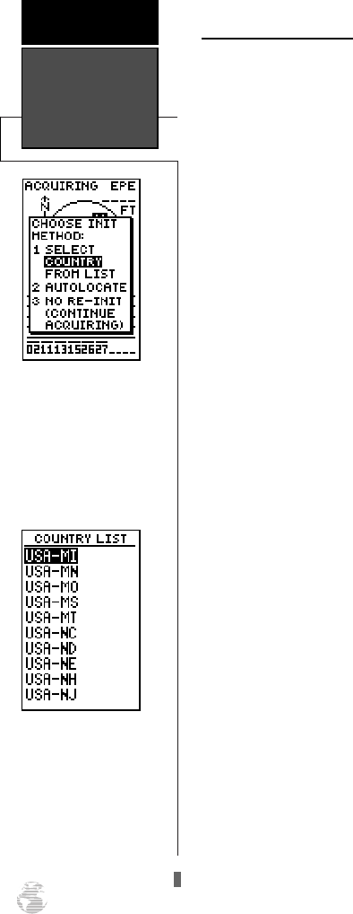
Once testing is complete, the welcome page will be
replaced by the status page, with the EZinit prompt
ready for you to select one of two initialization
methods:
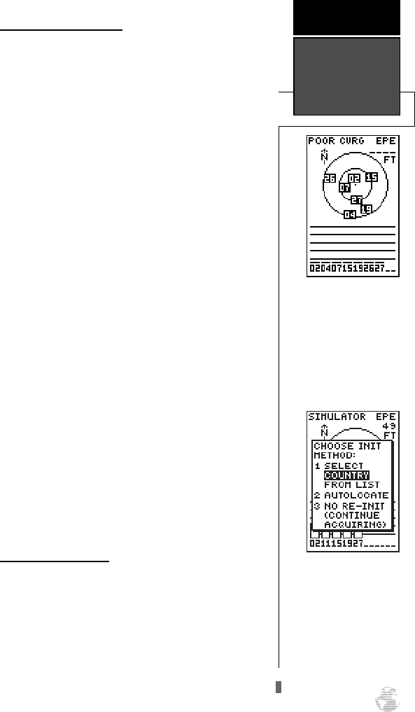
•Select Country––allows you to initialize the
receiver by selecting your present position from a
list of countries in the GPS 125 Sounder’s internal
database. This usually provides a position fix in a
few minutes.
•AutoLocate
TM
––allows the GPS 125 Sounder to
initialize itself and calculate a position fix without
knowing your present position. This usually pro-
vides a position fix in 7.5-15 minutes.
If the EZinit prompt has not automatically
appeared on the Satellite Page:
1. Press the
F
key.
Note: If the EZinit prompt appears at any time after
you have initialized the receiver (because satellite sig-
nals are being obstructed by trees, etc.), highlight ‘No
Re-Init’ with the arrow keypad and press ENTER.
To initialize the receiver:
1. If the ‘country’ option is not highlighted, press the
D
key repeatedly to move the field highlight to the ‘coun-
try’ option and press the
F
key.
Initialization
GETTING
STARTED
6
The EZinit prompt will
automatically appear if the
receiver needs to be initial-
ized. The prompt may also
appear during normal use if
the antenna is shaded.
Use the arrow keypad to
highlight the country,
region, or state of your pre-
sent position from the list
and press ENTER. If the
country is not listed, select
the closest country instead.
125 Man Rev B 7/23/98 11:47 AM Page 6
2. Use the
D
key to scroll through the list options until
the country of your present position appears.
3. Use
U
to highlight the country/state/region you’re in.
If the country you’re in is not listed, select another
country within 500 miles of your present position.
4. Press
F
to finish.
The GPS 125 Sounder will now begin searching for
the appropriate satellites for your location and should
acquire a position within a few minutes. You can verify
that you have acquired a position by watching the
Satellite Page transition to the Position Page (provided
you haven’t pressed any other buttons) or by looking for
a ‘2D NAV’ or ‘3D NAV’ status at the top left corner of
the Satellite Page.
Initialization Troubleshooting
If you have trouble initializing the receiver or
acquiring a position, check the following:
• Does the antenna have a clear view of the sky?
If there are nearby buildings, heavy tree cover, a
covered boat slip, etc., the unit may not be receiving
enough satellite signals to calculate a position.
• Have you selected the right country/state/region
from the EZinit list?
Check for the correct approximate lat/long on the
Position Page or reselect the appropriate country
from the list to restart the initialization.
• Have you moved more than 500 miles from the
last calculated position with the receiver off?
Reinitialize the receiver, selecting the country/state/
region of your new location from the EZinit list.
Your unit should now be initialized. If you want to
complete the Getting Started Tour at another time, you
may now turn the GPS 125 Sounder off (see below) or
you may continue.
To turn the GPS 125 Sounder off:
1. Press and hold
P
for approximately three seconds
until the receiver turns off.
7
The GPS 125 Sounder’s
Satellite Page will help you
determine which satellites
are in view and whether or
not any satellites are being
“shaded” or blocked from
the receiver’s antenna.
By monitoring the signal
strength bars at the bottom
of the page and the sky view,
you’ll be able to see how
moving to another area with
a clearer view of the sky will
improve satellite reception
and speed up signal
acquisition.
GETTING
STARTED
Initialization
125 Man Rev B 7/23/98 11:47 AM Page 7
Sounder Page
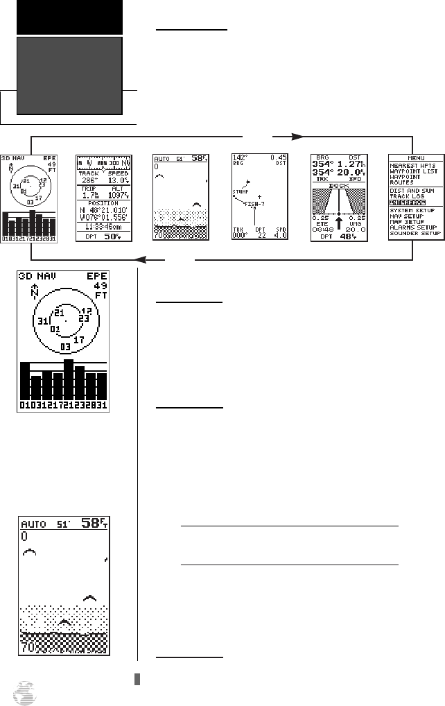
Primary Pages
The GPS 125 Sounder uses six primary “pages” to
give you information. The pages are arranged in a con-
tinual loop and can be easily viewed in forward or
reverse order by pressing either the Jor
Q
key.
Before we start the tour, let’s briefly look at these pages.
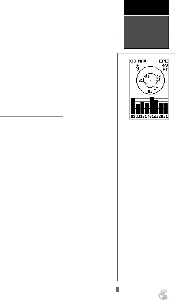
Satellite Page
The Satellite Page shows satellite positions and
signal strength. Satellite positions are shown using a
“birds-eye-view” display. Signal strength bars are shown
for each satellite in use. Satellite status and estimated
position error (EPE) are shown in the upper corners.
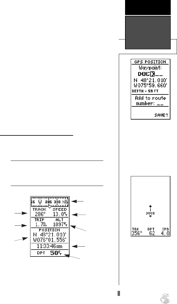
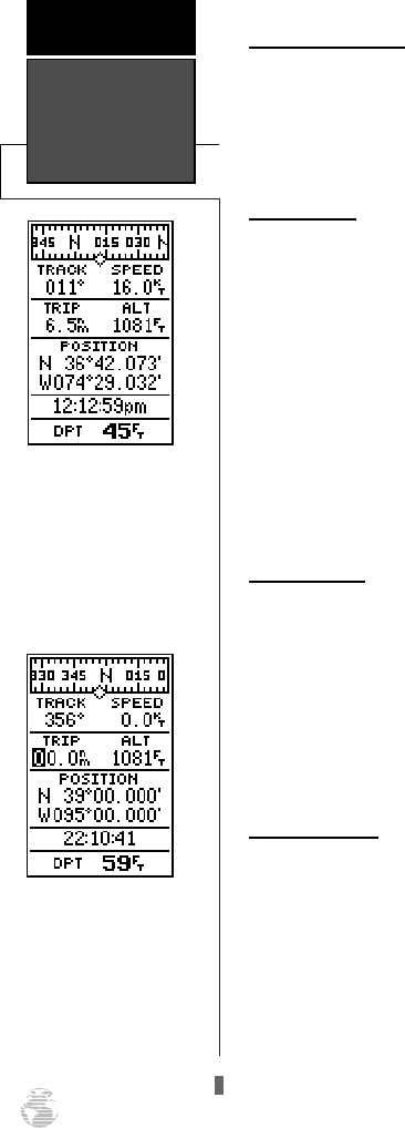
Position Page
The Position Page shows you where you are, what
direction you’re heading and how fast you’re going. The
top of the page contains a compass tape which is a
graphic representation of your heading. Your track and
speed are indicated immediately below, with the digital
depth displayed at the bottom of the page.
The graphic compass tape reflects your head-
ing only while you are moving.
The rest of the page shows your current position in
three dimensions: latitude, longitude and altitude. A
trip odometer and 12/24-hour clock are also provided.
Sounder Page
The Sounder Page gives a view of the water
beneath your boat while displaying sonar contacts and
bottom contour.
Primary Pages
GETTING
STARTED
8
Satellite Page
The Satellite Page will
allow you to monitor
satellite signal reception
and strength.
!
#
J
Q
125 Man Rev B 7/23/98 11:47 AM Page 8
Map Page
The Map Page acts as a window that allows you to
view your position, the “path” you have traveled over,
and nearby waypoints. A diamond icon in the center of
the screen represents your present position. As you
move, you will see a thin line, called a track log, appear
along the path you have just covered. Names of stored
waypoints can also be shown on the map.
The bottom corners of the page will always display
your current track and speed, with the digital depth
shown in the center. If you are navigating to a way-
point, highlighting an on-screen waypoint, or panning
the cursor, the corresponding distance and bearing will
be shown at the top corners.
Navigation Page
A navigation page gives you directional guidance
when going to a waypoint. The GPS 125 Sounder has
two navigation page choices: the Highway Page or the
Compass Page. The Highway Page is the default and
will be briefly explained here. The Compass Page is
covered on pg. 46.
The Highway Page uses a graphic highway to
show your movement in relation to your desired
course. The upper section shows bearing and distance
to the waypoint and your current track and speed. The
middle portion contains the actual highway. The bot-
tom of the page contains the estimated time enroute
(ETE) and your velocity made good (VMG).
Menu Page
The last primary page is the Menu Page. The
Menu Page gives you access to the GPS 125 Sounder’s
waypoint management, route, track log, and setup fea-
tures through a list of submenus.
Screen Backlighting
The GPS 125 Sounder features three levels of back-
lighting. Activate the backlight by pressing the POWER
key briefly. Each press of the button advances the back-
lighting to the next level and then turns it off.
Backlighting will remain on until turned off.
9
Map Page
The Map Page shows your
progress on a moving map
plotter and gives a bird’s-
eye-view of surrounding
waypoints.
GETTING
STARTED
Primary Pages
& Backlighting
Highway Page
With the Highway Page,
you will get graphic steer-
ing guidance in navigating
a route or to a single way-
point.
125 Man Rev B 7/23/98 11:47 AM Page 9
Getting Started Tour
Now that your GPS receiver has been initialized and
you are familiar with the primary pages, it’s time to take
a tour. This is a live tour and is to be conducted with
your unit installed and with the boat in the water. The
tour will take you through the receiver’s basic features
and functions as you move about on the water and
assumes that the GPS 125 Sounder is turned on, initial-
ized, and that you have not changed any of the factory
settings (units of measure, selectable fields, etc.). If
these settings have been changed, the pictures and
descriptions in this manual may not match what you
see on your screen.
Navigation Simulator
If you are not able to take the Getting Started tour
with your boat in the water, you may use the built-in
navigation simulator to practice using the GPS 125
Sounder. To use the simulator, see pg. 60.
Marking a Waypoint
To begin the live tour, let’s take the position you
have acquired (either by just initializing the unit or by
having turning the unit on) and mark it as a waypoint.
1. Press the
M
key to capture and hold your position.
To mark a position, you must have a 2D or 3D
fix, or have the receiver in simulator mode. If
you try to mark a position without a position fix,
a ‘No GPS Position’ message will be displayed.
The mark position page will appear, showing the
captured position and a default 3-digit waypoint name.
Let’s change the name something more meaningful, like
‘DOCK’.
1. Press the
D
key once to move the field highlight
from the ‘SAVE?’ field to the name field.
2. Press
F
to clear the default name.
3. Press and hold the
U
key to scroll through the alpha-
bet until the letter ‘D’ appears.
Marking A
Waypoint
GETTING
STARTED
10
To save a waypoint with the
default three-digit name,
simply press the MARK key
followed by the ENTER key.
The GPS 125 Sounder will
then return to the page pre-
viously displayed.
Press the UP arrow to move
forward through the alpha-
bet or numbers and DOWN
to move backward.
!
#
125 Man Rev B 7/23/98 11:47 AM Page 10
4. Press the
R
key once to move the character highlight
to the next character space.
5. Repeat steps 3 and 4 until the word ‘DOCK’ is shown.
6. Press
F
to complete entry of the name.
7. Press the
D
key twice to return the field highlight
to the ‘SAVE?’ field.
8. Press the
F
key to confirm that you want to save
the position as a waypoint named ‘DOCK’.
The mark position page will now be replaced by
the Position Page (or whatever page was displayed
prior to pressing the
M
key). The ‘DOCK’ waypoint
is now stored in the GPS 125 Sounder’s memory, and
will remain there until you manually remove it or clear
the receiver’s memory. For more on waypoint manage-
ment, see pg. 21-28.
Using the Position and Map Pages
Now that you’ve marked a position, let’s see how
the Position and Map Pages can be used to monitor
your progress as we head out into the open water.
As always, ensure your primary focus is on
boating traffic and monitor the GPS 125
Sounder briefly when operating your boat.
The direction you are moving (track) and your
speed are shown on the top of the Position Page, below
the graphic compass tape. The latitude, longitude, and
approximate altitude of your position--with a resettable
trip odometer--are displayed in the middle of the page,
with the time of day and digital depth shown below.
11
The arrow keypad is used
for all data entry. Use the
UP and DOWN keys to
select letters, numbers, or
menu options, and use the
LEFT and RIGHT keys to
move the cursor forward or
backward along the line.
GETTING
STARTED
Marking
Waypoint &
Map Page
The Map Page displays
your present position as a
diamond icon and provides
a real-time graphic “bread-
crumb” display of your
track right on the screen.
Altitude
Current Speed
Track Over
Ground
Graphic
Compass Tape
Tr i p
Odometer
Position
Display 12/24 Hour
Time
Digital Depth
!
#
125 Man Rev B 7/23/98 11:47 AM Page 11
Using the Position and Map Pages (continued)
Now let’s change the display to the Map Page and
watch the track log of our tour:
1. Press
J
to change from the Position Page to the
Map Page.
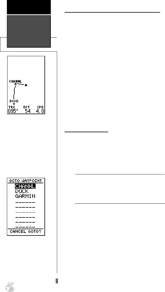
Your current position is shown as the diamond in
the middle of the screen. The dark circle below the dia-
mond represents the position you created, with the line
between the two showing your track.
1. Once you have reached an area that allows for gener-
al changes in direction without interfering in the pas-
sage of other boats, mark your current position again
and name this waypoint “CHANNL”. (See ‘Marking a
Waypoint’ on pg. 10-11).
2. Next, make a moderate turn in any direction safe for
navigation and proceed for another 3 minutes.
Going To a Waypoint
Once you’ve stored the ‘CHANNL’ waypoint in
memory, you can use the GPS 125 Sounder to guide
you to it by performing a simple GOTO. A GOTO is
simply the receiver drawing a straight-line course from
your present position to the destination you’ve selected.
Use caution when navigating. A “straight-line”
course reflects the shortest distance to a way-
point, and does not navigate around obstruc-
tions, such as land or buoys, etc.
Now that you have moved away from ‘CHANNL’ for
three minutes, let’s try navigating back to it.
To select a GOTO destination:
1. Press the
G
key. The GOTO waypoint page will
appear, displaying all the waypoints in memory in
alphabetical order.
2. Use
U
or
D
to highlight the ‘CHANNL’ waypoint.
3. Press the
F
key to confirm that you want to navi-
gate to the displayed waypoint. The Highway Page
(default) will appear.
Position/Map
Pages and
GOTO
GETTING
STARTED
12
The moving map’s default
screen orientation is track
up orientation. “Track up”
means that your current
direction of travel is always
up (or towards the top of)
the screen. It can also be set
for north up, or desired
track orientation through
the map setup page.
The GOTO waypoint page
allows you to select a desti-
nation from a list of all
available waypoints in the
GPS 125 Sounder’s
memory.
!
#
125 Man Rev B 7/23/98 11:47 AM Page 12
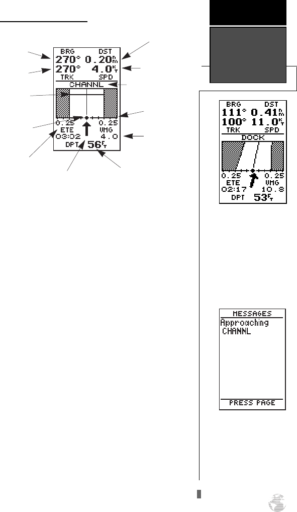
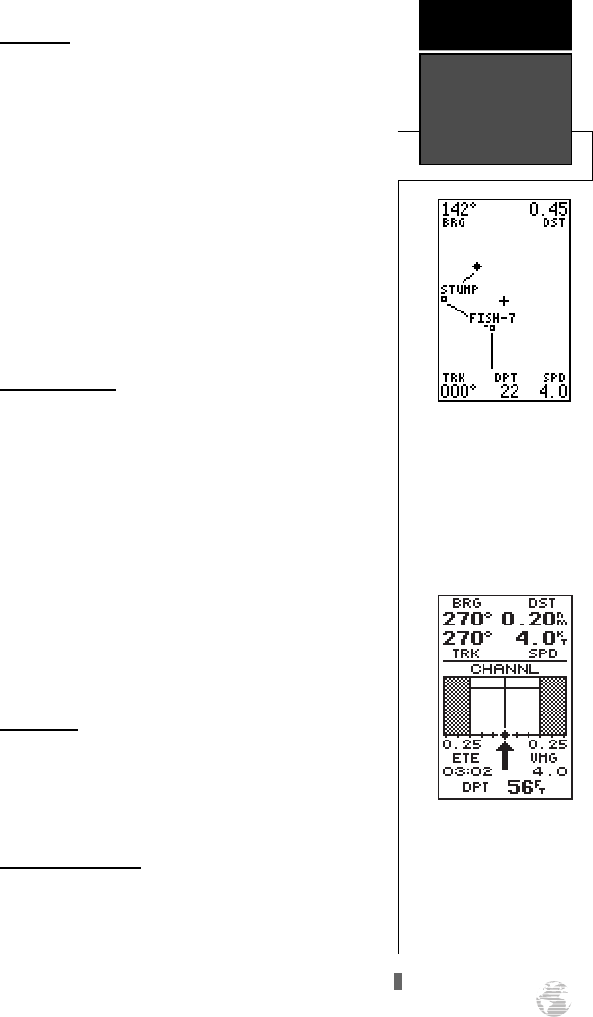
Using the Highway Page
The GPS 125 Sounder’s Highway Page provides
graphic steering guidance to a destination, with an
emphasis on a straight-line course to the desired way-
point and the distance and direction you are off course.
The bearing and distance to a waypoint, along with
your current track and speed are displayed at the top of
the screen, with your estimated time enroute (ETE) and
velocity made good (VMG), or the speed you are
approaching your destination, shown at the bottom.
As you head toward your destination, the middle
section of the screen provides visual guidance to your
waypoint on a moving graphic “highway”.
Your present position is represented by the dia-
mond in the center of the course deviation scale. The
line down the middle of the highway represents your
desired track.
As you navigate toward a waypoint, the highway
will actually move, indicating the direction you’re off
course, relative to the position diamond on the CDI
scale. When the highway is pointing straight up the
screen, the waypoint is directly ahead. If the destina-
tion waypoint is to the left, the top of the highway will
lead toward the left, and vice versa. To stay on course
simply steer in the direction the highway leads (left or
right) until the highway leads straight up the page.
13
A waypoint is directly
ahead when the highway is
pointing straight up. In the
above example, the way-
point is to the right (111º) of
our present course (100º).
Turn right until the highway
points straight up the
screen.
GETTING
STARTED
Using the
Highway Page
Once you are one minute
from the destination (based
on your present speed and
course), an arrival message
will appear on the message
page.
Bearing to
Waypoint
Destination
Waypoint
“Finish Line” CDI Scale
Distance to
Waypoint
Destination Waypoint
Digital Depth
Velocity Made
Good
Current Speed
Current Track
Estimated
Time Enroute
Position Diamond
Pointer to Waypoint
125 Man Rev B 7/23/98 11:47 AM Page 13
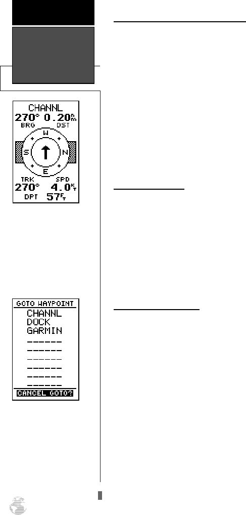
Using the Highway Page (continued)
While navigating, you may use the Compass Page
(see picture below left) instead of the Highway Page.
To select the Compass Page:
1. While viewing the Highway Page press
F
twice.
The Compass Page will now become the displayed
navigation page. This page provides a directional point-
er to your destination by using a compass display to
show direction of travel. This provides better steering
guidance at slower speeds for travel with many direc-
tional changes.
To return to the Highway Page, press ENTER twice.
Cancelling a GOTO
If you decide to stop navigating to the active way-
point waypoint, all you have to do is cancel the GOTO.
To cancel an active GOTO:
1. Press the
G
key.
2. Use the arrow keypad to move the field highlight to the
‘CANCEL GOTO?’ prompt at the bottom of the page and
press
F
.
Using the Sounder Page
Now that you have learned the basics of GPS
Navigation, let’s briefly look at how the GPS 125
Sounder works for you as a fishfinder. The fishfinding
features are covered in detail on pg. 37-40.
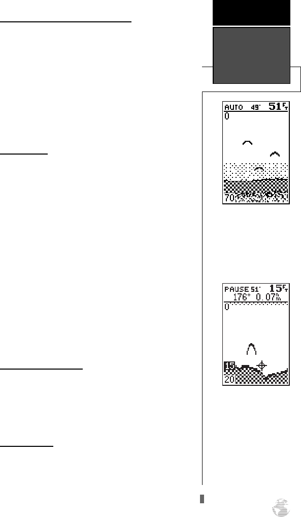
The top of the Sounder Page shows the range mode
being used, the water temperature (if using a tempera-
ture-sensitive transducer), and the digital depth, while
the middle of the page contains a right-to-left moving
sonar image of the water beneath your boat. (Note:
items appear as they pass under your transducer. Those
objects appearing on the right side of the screen are
closer to you than those objects on the left.) Fish are
displayed as a darkened arch or a fish icon in three dif-
ferent sizes. Thermoclines (layers of water separating
warmer water above and cooler water below) appear as
dotted patterns just above the bottom.
Highway/
Sounder Page &
Cancelling GOTO
GETTING
STARTED
14
The 125 Sounder will also
provide steering guidance
with a graphic Compass
Page.
To change the display from
the Highway Page, press
ENTER twice.
Once a GOTO is activated,
the GPS 125 Sounder pro-
vides steering guidance
until the GOTO is canceled.
To cancel a GOTO, high-
light the cancel prompt at
the bottom of the page and
press ENTER.
125 Man Rev B 7/23/98 11:47 AM Page 14
Using the Sounder Page (continued)
The area of strongest sonar return (whiteline) is
displayed as light and dark checkering. Typically, the
bottom will be the primary source of the whiteline. A
thin whiteline indicates a softer bottom while a thicker
whiteline shows a harder bottom. A black line is used
to show the point where water meets the whiteline.
This black line will follow the bottom contour, along
with any significant objects lying on the bottom. Along
the left side of the screen (typically) is an adjustable
scale which shows the current display’s range of depth.
Range Modes
The GPS 125 Sounder uses two range modes: auto
and manual. ‘Auto’ displays the most information pos-
sible while continuously displaying the bottom.
‘Manual’ lets you select the displayed range. You may
switch between auto and manual modes by using the
arrow keypad or by using the sounder setup menu.
To switch from auto to manual mode:
1. Press the
U
or
D
keys until the desired depth
range is displayed on the depth scale at the left side
of the page.
2. Press
F
to confirm the selected range.
To switch from manual to auto mode:
1. Press the arrow keypad up or down until a repeated
beep sounds. ‘Auto’ will be shown in the range field at
the top left corner of the screen, and press
F
.
Underwater waypoints
The underwater waypoint feature marks a way-
point’s position and its depth. This makes it easier to
find and use an object such as a stump for a future
fishing location. For instructions on marking an under-
water waypoint, see pg. 38.
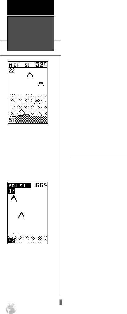
Sounder Zoom
The sounder zoom function allows you to see the
current display picture at 2 times (2X) or 4 times (4X)
magnification. 2X means that the screen displayed will
now cover 1/2 the range you were originally viewing in
twice the detail, and 4X shows 1/4 the original range at
four times the detail. Because less area is being shown
(in a zoom screen) objects can be seen in greater detail.
15
GARMIN’s exclusive See-
Thru technology will allow
you to distinguish sonar tar-
gets from bottom clutter and
thermoclines.
GETTING
STARTED
Sounder Page,
Range Modes, &
Sounder Zoom
Use the target cursor to
mark the desired underwa-
ter location.
Note: The bearing and
range shown are to the cur-
sor’s location from your pre-
sent position.
125 Man Rev B 7/23/98 11:47 AM Page 15
The zoom function is accessed by using the IN and
OUT key when viewing the Sounder Page.
Once activated, the zoomed picture becomes the
Sounder Page display. Note: The zoom function can
only be deactivated by pressing the OUT key until the
original zoom scale appears.
The zoom function operates in either Auto range or
Manual range. Zooming while in Auto will continue to
follow the bottom contour, while zooming in Manual
will show the selected depth.
To access the sounder zoom function:
1. While viewing the Sounder Page, press
I
once.
The 2X screen will appear. Note: the current zoom scale
will be displayed in the upper left corner of the screen.
2. Press
I
once more to advance to the 4X screen.
3. To deactivate the sounder zoom function, press
I
once. You may also press and hold
H
until the original
scale picture appears and a triple beep sounds.
Moving the Zoom Window
You may move the displayed range on a zoomed
screen at any time, just as you would a non-zoom
screen, by pressing the arrow keypad up or down. This
will move the zoom “window”.
If you prefer to keep the window in its new posi-
tion, you will need to save the change. Note: Saving the
new window position requires different steps if you are
in Auto range when you move the window versus being
in Manual when the window is moved.
To save a zoom window range in Auto:
1. Press the
R
keypad up to view a shallower range or
down to view a deeper range. The range scale on the
left side of the zoomed picture will be highlighted.
2. When the window reaches the desired range, press
F
to accept. A ‘Change To Manual Range?’ window
will appear. Highlight ‘Yes” and press
F
.
3. If you do not want to save the range, highlight ‘No’ and
press
F
. You may then resume manually moving the
zoom window.
4. Press
Q
at any time to return to an auto range mode
display.
Sounder Zoom
& Zoom
Window
GETTING
STARTED
16
Pressing the IN key once
while on the Sounder Page
activates the 2X Zoom.
The zoom window may be
moved at any time by using
the arrow keypad.
125 Man Rev B 7/23/98 11:47 AM Page 16
Moving the Zoom Window (continued)
To save a zoom window range in Manual:
1. Press the
R
keypad up to view a shallower range or
down to view a deeper range. The range scale on the
left side of the zoomed picture will be highlighted.
2. When the window reaches the desired range, press
F
to accept.
3. If you do not want to save the range, press
Q
to
return to the previous window range.
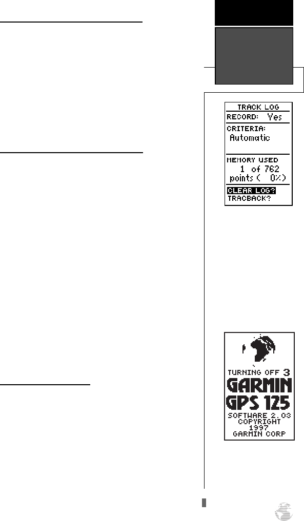
Clearing a Cluttered Map Page Display
After you’ve used the GPS 125 Sounder for a few
trips, you may find that your map display has become
a bit messy from keeping track of your every move. For
practice, let’s clean up the screen by clearing the track
log (the plot points left on the Map Page) we’ve just
created during the Getting Started Tour.
1. Press
J
or
Q
until the Menu Page appears.
2. Use the
D
key to move the field highlight to the
‘TRACK LOG’ option.
3. Press
F
to access the track log page.
4. Press the
U
key twice to highlight the ‘CLEAR LOG?’
option. The clear log confirmation page will appear.
5. Use the
L
key to highlight the ‘Yes?’ prompt.
6. Press
F
to finish.
Turning the Receiver Off
You’ve now gone through the basic operation of
your new GPS receiver and probably know a little more
than you think about how it works. We encourage you
to experiment with the GPS 125 Sounder until it
becomes an extension of your own navigation skills. If
you encounter any problems using the unit or want to
take advantage of the GPS 125 Sounder’s more
advanced features, refer to the reference section.
To turn the GPS 125 Sounder off:
1. Press and hold the
P
key for 3 seconds.
17
Highlight the ‘CLEAR
LOG?’ prompt and press
ENTER to clear the track
log.
Note: Once all 768 points
are used during normal
operation, the oldest point
will be continuously deleted
to make room for the latest
track log point to be stored.
GETTING
STARTED
Clearing the
Map Page &
Power OFF
Holding the POWER key
for three seconds ensures
against unwanted shut-off
by accidentally pressing the
key.
125 Man Rev B 7/23/98 11:47 AM Page 17
Satellite Page
The Satellite Page displays the status of various
receiver functions. The status information will help you
understand what the GPS 125 Sounder is doing at any
given time, and tell you whether or not the receiver has
calculated a position fix.
Sky View and Signal Strength Bars
The sky view and signal strength bars give you an
indication of what satellites are visible to the receiver,
whether or not they are being used to calculate a posi-
tion fix, and the signal quality. The sky view in the cen-
ter of the page shows a bird’s-eye view of the position of
each satellite relative to the receiver’s last known posi-
tion. The outer circle represents the horizon (north up);
the inner circle is 45º above the horizon; and the center
point is a position directly overhead.
When the receiver is looking for a particular satel-
lite, the corresponding signal strength bar will be blank
and the sky view indicator will remain highlighted in
reverse video. Once the receiver has found the satellite,
a hollow signal strength bar will appear, indicating that
the satellite has been found and the receiver is collect-
ing data from it. The satellite number in the sky view
will also change from reverse video to normal presenta-
tion. As soon as the GPS 125 Sounder has collected the
necessary data to use the satellite for positioning, the
hollow bar will become solid.
Satellite Page
Overview
REFERENCE
18
When backlighting is on, a
bulb icon will appear on the
Satellite Page.
Use the icon to determine if
backlighting is turned on
during daylight hours.
Satellites being tracked but
blocked from use (03,17)
will be displayed in reverse
video, with the correspond-
ing signal strength bar
hollow.
Status
Satellite
Sky View
Satellite
Numbers
Estimated
Position Error
125 Man Rev B 7/23/98 11:47 AM Page 18
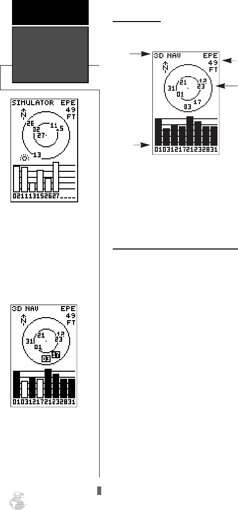
Receiver Status and EPE
Receiver status is indicated at the top left of the
screen, with the current horizontal accuracy (estimated
position error, in feet or meters) at the top right. The
status will show one of the following conditions:
Searching— the GPS 125 Sounder is looking for
any available satellites in view.
AutoLocate
TM
—the GPS 125 Sounder is initializ-
ing and collecting new almanac data. This process
can take 7.5 to 15 minutes.
Acquiring— the receiver is collecting data from
available satellites, but has not collected enough
data to calculate a 2D fix.
2D Nav (2D Navigation)–– at least three satellites
with good geometry have been locked onto and a
2-dimensional position fix (latitude and longitude)
is being calculated. ‘2D Diff’ will appear when you
are receiving DGPS corrections in 2D mode.
3D Nav (3D Navigation)— at least four satellites
with good geometry have been locked onto, and
your position is now being calculated in latitude,
longitude and altitude. ‘3D Diff’ will appear when
you are receiving DGPS corrections in 3D mode.
Poor Cvrg (Poor GPS Coverage)— the receiver is
no longer tracking enough satellites for a 2D or 3D
fix.
Not Usable— the receiver is unusable, possibly
due to incorrect initialization or abnormal satellite
conditions. Turn the unit off and back on to reset.
SIM (Simulating Navigation)— the receiver is in
simulator mode.
EZinit Option Prompt
The Satellite Page also provides access to the EZinit
prompt whenever a position fix has not been calculated
(the unit must be in searching, AutoLocate, acquiring,
simulator or poor coverage status). This allows you to
manually reinitialize the unit (see pg. 6-7 for instruc-
tions), and is useful if you have traveled over 500 miles
with the receiver off and you know it must be initial-
ized to your new position (the GPS 125 Sounder will
automatically offer the EZinit prompt after 10 minutes
of unsuccessful satellite acquisition).
19
A ‘POOR CVRG’ status
will appear on the Satellite
Page if the receiver has lost
the satellites required to
compute a fix. Make sure
the external antenna is not
covered and is connected to
the GPS 125 Sounder.
REFERENCE
Receiver Status
& EZinit
If you travel more than 500
miles with the receiver off,
reinitialize the unit to your
new position by using the
EZinit feature. To access
EZinit, press ENTER from
the Satellite Page before any
satellites are acquired.
125 Man Rev B 7/23/98 11:47 AM Page 19
Screen Backlighting
The GPS 125 Sounder features three levels of back-
lighting. Activate the backlight by pressing the POWER
key briefly. Each press of the button advances the back-
lighting to the next level and then turns it off.
Backlighting will remain on until turned off.
Position Page
The GPS 125 Sounder’s Position Page shows you
where you are, the direction you are heading, and your
speed (up to 99.9 mph), and is most useful when you
are traveling without an active destination waypoint. A
compass tape at the top of the page displays your cardi-
nal heading (while moving), with current track and
speed over the ground indicated below. The rest of the
page shows your present position in three dimensions
(latitude, longitude and altitude). The units of measure
for speed, distance, position and altitude are user-selec-
table through the navigation setup menu (see pg. 53).
The 12/24-hour clock and time offset options are avail-
able from the system setup menu (see pg. 52).
Trip Odometer
The Position Page also features a resettable trip
odometer to measure your total distance traveled.
To reset the trip odometer:
1. Press the
D
key until the trip field is highlighted.
2. Press
F,
followed by
L
.
3. Press
F
to finish.
Altitude Display
When the GPS 125 Sounder is acquiring satellites or
navigating in the 2D mode, the last known altitude will
be used to compute your position. If the altitude shown
is off by several hundred feet, you can manually enter
your altitude for greater accuracy. Note that GPS alti-
tudes can fluxuate due to errors.
To enter an altitude:
1. Press the
D
key until the altitude field is highlighted
and press
F
.
2. Use the arrow keypad to enter the altitude and press
F
.
Backlighting &
Position Page
REFERENCE
20
The speed and track dis-
played on the Position Page
may fluxuate at slow speeds
(or when you’re standing
still) because of position
errors caused by Selective
Availability.
To reset the trip odometer,
highlight the trip field and
press ENTER. Use the
LEFT arrow key to clear the
distance field, and press
ENTER to confirm.
125 Man Rev B 7/23/98 11:47 AM Page 20
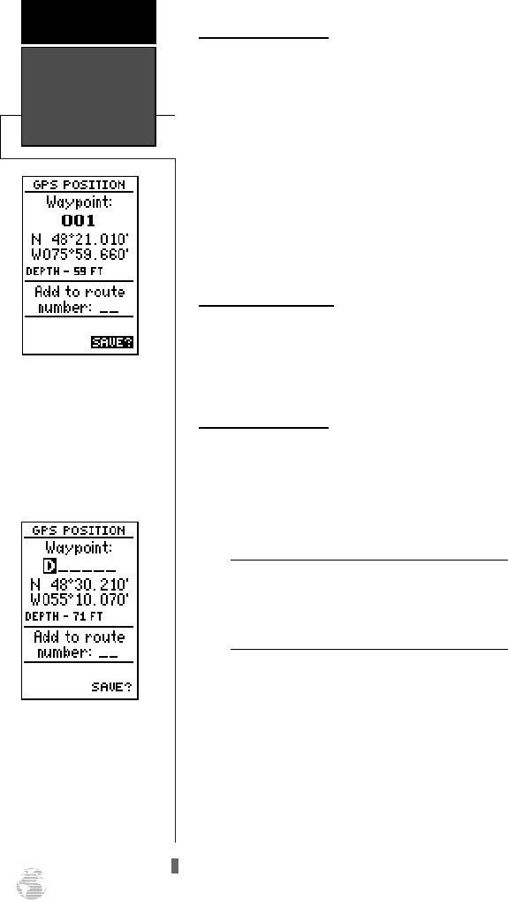
Marking and Saving Waypoints
Knowing your present position is only part of any
navigation equation. You also need to keep track of
where you’ve been and where you are going.
Waypoints serve as electronic markers that let you keep
track of starting points, destinations, navaids and any
other important position.
The GPS 125 Sounder allows you to mark, store
and use up to 250 waypoints. A waypoint position can
be entered by taking an instant electronic fix, by manu-
ally entering coordinates, or by entering range and
bearing in reference to an existing waypoint. If you try
to mark a waypoint without having a position fix,
you’ll be notified with a ‘No GPS Position’ message.
To mark your present position:
1. Press the
M
key to capture your position.
The mark position page will appear, showing the
captured position and a default 3-digit waypoint name.
To change the default position name:
1. Press the
D
key once to move the field highlight
from the ‘SAVE?’ field to the name field.
2. Press
F
to clear any existing data and begin entry
of the name.
3. Use the arrow keypad to enter the name.
4. Press
F
to confirm the waypoint name. The field
highlight will move to the “comment” field.
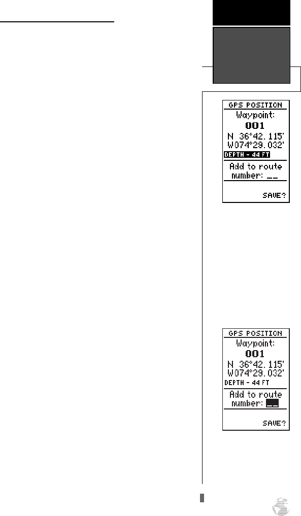
If you’d like to add this waypoint to a route:
1. Press
D
once to highlight the route field and press
the
F
key.
2. Use the
U
or
D
keys to enter a route number
and press
F
.
3. Press the
F
key again to save the waypoint.
If you do not want to add this waypoint to a
route:
1. Highlight the ‘SAVE?’ field and press the
F
key.
21
The GPS 125 Sounder will
automatically name new
waypoints with a default
three-digit name, with the
current digital depth as the
default comment. You may
then highlight either field,
press ENTER, and enter
your own name or
comment.
REFERENCE
Marking &
Saving
Waypoints
To add a waypoint to a
route as you are marking its
position, enter the desired
route number, highlight
‘SAVE?’ and press ENTER.
125 Man Rev B 7/23/98 11:47 AM Page 21
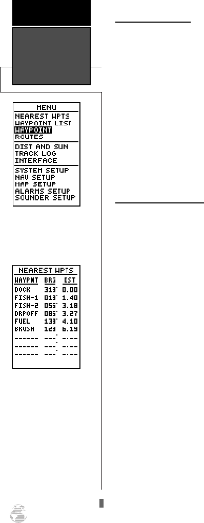
Waypoint Submenus
The GPS 125 Sounder has three waypoint submenu
pages that let you manage a large number of waypoints
quickly and efficiently. The nearest waypoints, waypoint
list and waypoint definition pages are accessed through
the Menu Page.
To select a waypoint submenu page:
1. Press
J
or
Q
until the Menu Page appears.
2. Use the
U
and
D
keys to highlight the waypoint
submenu page you want to use.
3. Press
F
to display the submenu page.
4. To return to the Menu Page, press the
J
key.
Nearest Waypoints Page
The nearest waypoints page shows the nine nearest
waypoints that are within 100 miles of your present
position, with the bearing and range noted for each
waypoint. During an emergency, the nearest waypoints
page can give you the closest points of safety in your
area at a glance.
The nearest waypoints page will also let you retrieve
a waypoint definition page or go to a selected waypoint
right from the list.
To review the waypoint definition page of a high-
lighted waypoint from the list:
1. Press the
F
key.
To return to the nearest waypoint page (when the
‘DONE?’ field is highlighted):
1. Press the
F
key.
To go to a highlighted list waypoint:
1. Use the
U
and
D
keys to highlight a listed way-
point.
2. To select a highlighted nearest waypoint as a destina-
tion, press the
G
key.
3. Once the GOTO waypoint page appears, press the
F
key to confirm the selected waypoint as your
destination.
Nearest
Waypoints Page
REFERENCE
22
To select a waypoint sub-
menu, highlight the desired
option and press ENTER.
The compass heading
(BRG) and distance (DST)
to the nine nearest way-
points are updated continu-
ously.
125 Man Rev B 7/23/98 11:47 AM Page 22
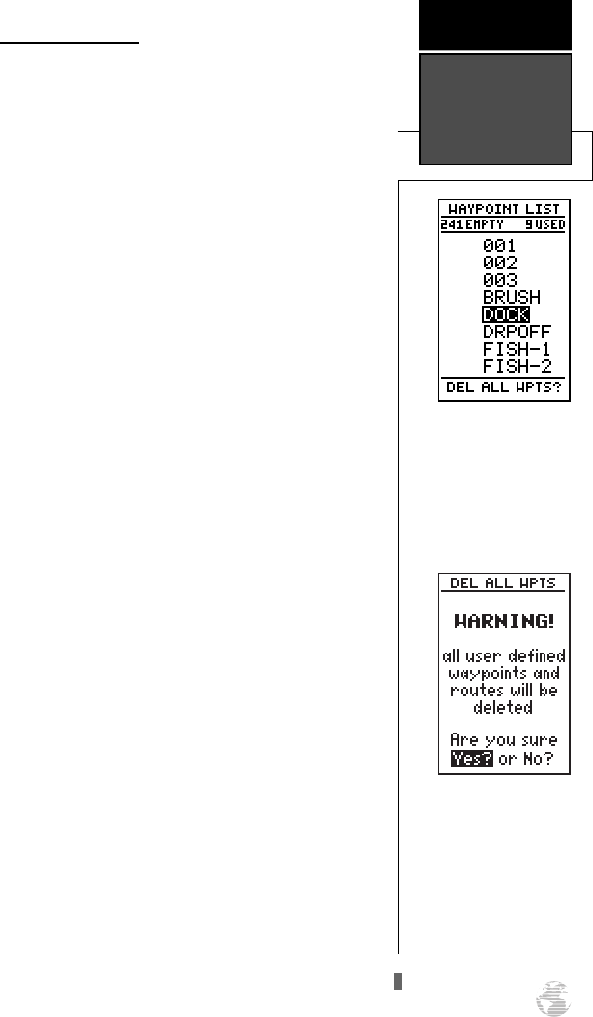
Waypoint List Page
The waypoint list page provides you with a com-
plete list of all waypoints currently stored in the GPS
125 Sounder. The total number of used and empty
waypoints is indicated above the waypoint list. From
the waypoint list page, you can retrieve a waypoint def-
inition page, delete all user-defined waypoints, or go to
a selected waypoint. If a waypoint is currently used in a
route, the lowest route number will be indicated to the
left of the waypoint name.
To review the waypoint definition page of a high-
lighted list waypoint:
1. Press the
F
key.
To return to the waypoint list page (ensure
‘DONE?’ is highlighted):
1. Press the
F
key.
To go to a list waypoint:
1. Use the
U
and
D
keys to scroll through the list
and select a waypoint.
2. To select a highlighted waypoint as a destination,
press the
G
key.
3. Once the GOTO waypoint page appears, press the
F
key to confirm the selected waypoint as your
destination.
To delete all user-defined waypoints:
1. Use the
U
or
D
keys to move the cursor high-
light to the ‘DEL ALL WPTS?’ field.
2. Press the
F
key.
A warning page will appear, asking if you are sure
you want to delete all user-defined waypoints and
routes. If you want to continue and delete:
1. Press the
L
key to highlight the ‘Yes?’ field.
2. Press the
F
key.
3. Press the
Q
key to return to the Menu Page.
If you do not want to delete all waypoints:
1. Highlight ‘No?’ and press
F
.
23
The total number of used
and available waypoints is
indicated at the top of the
page. Route waypoints are
indicated by an ‘R__’.
Above, R03 means route 3.
REFERENCE
Waypoint List
Page
Deleting all user waypoints
will also delete all routes
stored in memory.
125 Man Rev B 7/23/98 11:47 AM Page 23
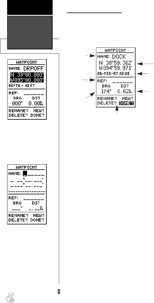
Waypoint Definition Page
The last of the three waypoint management pages is
the waypoint definition page. This page lets you create
new waypoints manually, or review and edit existing
waypoints.
To create a new waypoint manually, you’ll need to
know its position coordinates or its distance and bear-
ing from an existing waypoint.
To create a waypoint by entering coordinates:
1. If a waypoint is currently displayed in the name field,
highlight ‘NEW?’ and press
F
. Then press the
L
key to clear the name field.
2. If a waypoint is not displayed, move the cursor to the
name field and enter the new waypoint’s name.
3. Use
U
and
D
to enter your waypoint name and
use
L
and
R
to move to the next character position.
4. Press
F
to confirm the waypoint name. The posi-
tion field will now become highlighted, with the receiv-
er’s last known position shown, if one exists.
5. Press
F
to begin entry of the position.
6. Use the
U
and
D
keys to enter your position, and
use the
L
and
R
keys to move to each character
field.
7. Press
F
to confirm and save your coordinates. The
default waypoint comment (UTC date and time of cre-
ation) will appear, and the highlight will move to
‘DONE?’.
8. Press the
F
key to return to the Menu Page.
Waypoint
Definition Page
REFERENCE
24
Use the waypoint definition
page to review, rename, or
delete stored waypoints and
to create new waypoints
manually.
To create a new waypoint
by manually entering coor-
dinates or by referencing an
existing waypoint, highlight
the ‘NEW?’ prompt and
press the ENTER key.
Waypoint
Name
Reference
Waypoint Distance from
Reference
Waypoint
Position
Coordinates
Bearing from
Reference
Waypoint
Function Prompts
Waypoint Comment
125 Man Rev B 7/23/98 11:47 AM Page 24
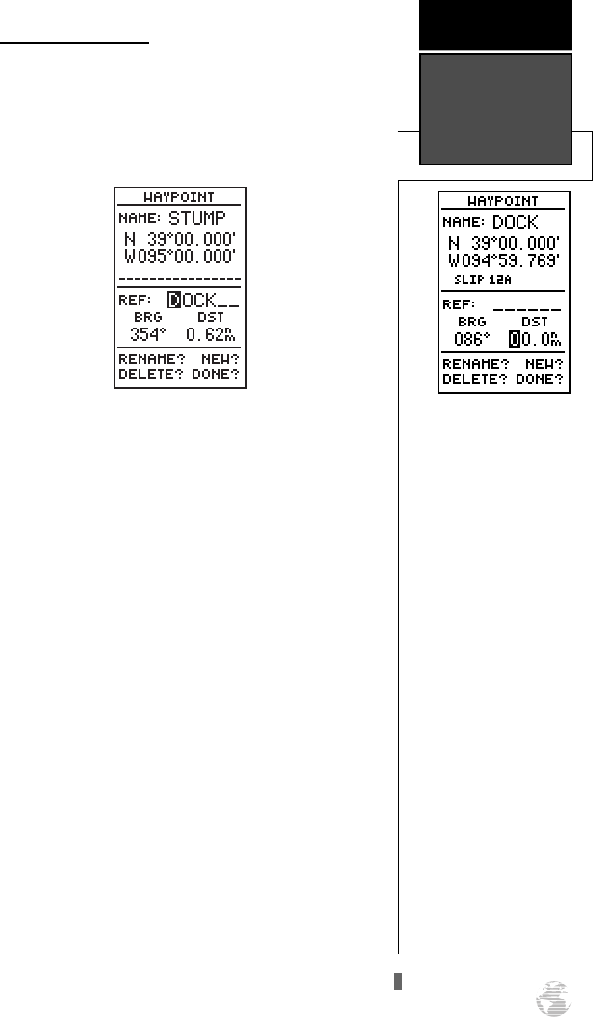
The GPS 125 Sounder’s
advanced waypoint and
planning features allow you
to create new waypoints
and practice navigation
without ever leaving the
slip.
If you create a new way-
point by entering coordi-
nates from a map, you may
want to re-mark the way-
point’s exact position once
you get there. To re-define
an existing waypoint’s posi-
tion coordinates from the
waypoint definition page,
simply highlight the ‘DST’
field and press ENTER. Use
the LEFT arrow key to set
the distance to 0.00, and
press ENTER to confirm.
The old coordinates will be
replaced by the coordinates
of your present position
(you must have a valid 2D
or 3D position fix).
Reference Waypoints
To create a new waypoint manually without know-
ing its position coordinates, you’ll need to enter its
bearing and distance from an existing waypoint. The
GPS 125 Sounder will then calculate the position coor-
dinates for you.
To create a new waypoint by referencing a stored
waypoint:
1. Press
U
until the ‘NEW?’ field is highlighted.
2. Press
F
.
3. Enter the name of your new waypoint.
4. Press the
F
key to confirm the waypoint name.
The position field will now become highlighted, with
the receiver’s last known position shown.
5. Press
D
to move the cursor to the reference field.
6. Press
F
to begin entry of the reference waypoint.
7. Use the arrow keypad to enter the waypoint name.
8. Press the
F
key to confirm your entry.
9. Enter the bearing and distance of your new waypoint
from the reference waypoint. Remember to use the
F
key to begin entry and confirm each field. The
coordinates will be calculated and saved for your
new waypoint.
10. Press the
F
key (with the ‘DONE?’ field highlight-
ed) to return to the Menu Page.
25
REFERENCE
Reference
Waypoints
125 Man Rev B 7/23/98 11:47 AM Page 25
Editing Existing Waypoints
The waypoint definition page also allows you to
change the name, coordinates, comment or reference
waypoint field for a stored waypoint. (Fields shown on
pg. 24.)
To edit the name, coordinates, comment, or refer-
ence waypoint field:
1. Use
U
and
D
to highlight the field you want to
edit.
2. Press
F
to begin entry in the selected field.
3. Enter your new data.
4. Press the
F
key to confirm your changes.
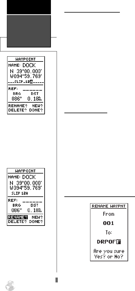
Waypoint Comments
Each waypoint stored in the GPS 125 Sounder has a
user-defined 16-character comment field. The default
comment is the UTC date and time of the waypoint’s
creation.
To change or add a comment:
1. Use the
U
and
D
keys to highlight the comment
field.
2. Press
F
to begin entry of your comment.
3. Enter the comment and press the
F
key to confirm.
Renaming and Deleting Waypoints
The rename and delete function fields are located at
the bottom left of the waypoint definition page (you’ll
need to use the
L
key to move the field highlightout of
its standard up-and-down scrolling sequence).
Editing,Deleting,
& Renaming
Waypoints
REFERENCE
26
The waypoint comment
field will automatically dis-
play the date and time of
creation of the waypoint.
You may replace this with a
16-character custom com-
ment at any time.
To access the rename func-
tion from the waypoint def-
inition page, highlight the
‘RENAME?’ prompt and
press ENTER.
125 Man Rev B 7/23/98 11:47 AM Page 26
To rename a stored waypoint:
1. Highlight the ‘RENAME?’ field and press
F
.
2. Enter the new waypoint name and press
F
.
3. Press the
F
key to confirm your changes.
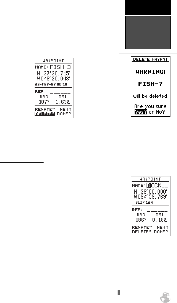
To delete a stored waypoint:
1. Highlight the ‘DELETE?’ field and press
F
.
2. Press the
L
key to select the ‘YES’ prompt.
3. Press
F
to delete the waypoint.
Scanning Waypoints
As you manually enter a waypoint’s name, the GPS
125 Sounder’s waypoint scanning feature will automati-
cally display the first numerical or alphabetical match
of the character you have entered to that point. This
helps eliminate the need to always enter a waypoint’s
complete name.
To scan waypoints from a waypoint field:
1. Highlight the waypoint name field and press
F
.
2. Press the
L
key to clear the name field.
3. Use the
U
and
D
keys to scroll through way-
points.
4. If you have more than one waypoint that begins with
the same letter or number, you must use the
R
key to
move to the next character positions as needed. Only
the first character match is listed for each character
set.
5. Once you’ve found the desired waypoint, press
F
.
27
A warning page will ask you
for confirmation to delete
the selected waypoint.
Note: If a waypoint is part
of a route, you will need to
remove it from the route
before it can be deleted. (See
pg. 36)
REFERENCE
Editing and
Scanning
Waypoints
Waypoint names will
appear alphabetically
when scanning waypoints.
If two waypoints begin with
the same letter(s) you must
move the cursor to the first
letter they do not have in
common for them to appear.
125 Man Rev B 7/23/98 11:47 AM Page 27
Selecting a GOTO Destination
The GPS 125 Sounder provides four ways to navi-
gate to a destination: GOTO, MOB, TracBack and route
navigation. The most basic method of selecting a desti-
nation is the GOTO function, which lets you choose
any stored waypoint as the destination and quickly sets
a direct course from your present position.
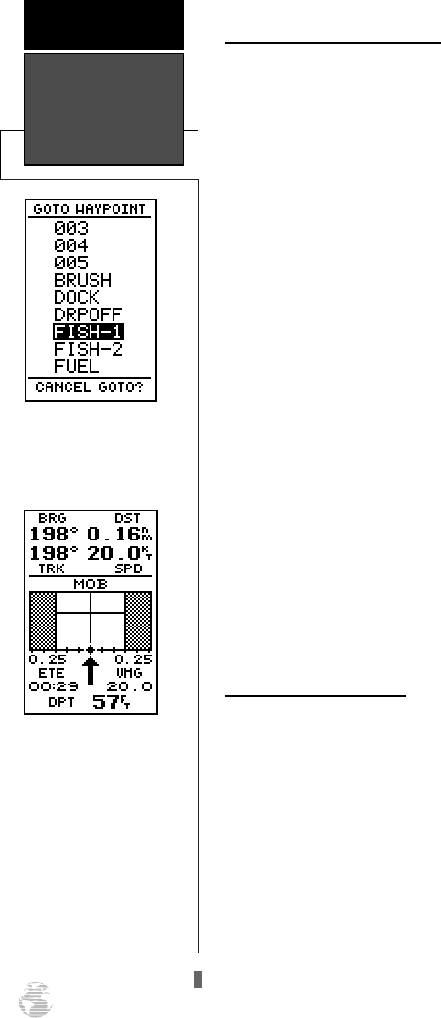
To activate the GOTO function:
1. Press the
G
key. The GOTO waypoint list, an alpha-
betical list of all available waypoints, will appear.
2. Use the
U
and
D
keys to select the waypoint you
want to navigate to (it may already be highlighted).
3. Press the
F
key to confirm, or
Q
to stop selec-
tion of a GOTO destination and return to the previous
page.
Once a GOTO waypoint has been activated, the
Compass Page or Highway Page will provide steering
guidance to the destination until either the GOTO is
cancelled or the unit has resumed navigating the active
route (see pg. 36).
To cancel an active GOTO:
1. Press the
G
key.
2. Use the arrow keypad to move the field highlight to the
‘CANCEL GOTO?’ prompt at the bottom of the page and
press
F
.
Man Overboard Function
The GPS 125 Sounder’s man overboard function
(MOB) lets you simultaneously mark and set a course to
a position for quick response to passing positions (like
the spot where your hat blew overboard).
To activate the MOB mode:
1. Press the
B
key. The GOTO waypoint page will
appear with ‘MOB’ selected as the default destination.
2. Press the
F
key to begin MOB navigation.
The GPS 125 Sounder will now guide you to the
MOB waypoint until the MOB GOTO is cancelled (see
“to cancel an active GOTO” above). If you want to save
the MOB waypoint, be sure to rename it, because it will
be overwritten the next time a MOB is executed.
Starting/Stopping
a GOTO & MOB
REFERENCE
28
Select a destination way-
point from the GOTO way-
point list.
Once the MOB mode has
been activated, steering
guidance will be provided
by the Highway or Compass
Page. Activating another
MOB will replace the previ-
ous MOB waypoint.
125 Man Rev B 7/23/98 11:47 AM Page 28
TracBack Navigation
The third method of navigating to a destination is
by using the GPS 125 Sounder’s TracBack feature. The
TracBack function allows you to quickly and easily
retrace your path using the track log automatically
stored in the receiver’s memory. The advantage of the
TracBack feature is to eliminate the need to mark way-
points along the way and manually create and activate
a route back to where you began your trip.
The TracBack route is created by reducing your
current track log into a route of up to 30 waypoints,
and activating an inverted route along those points.
Once activated, a TracBack route will lead you back to
the oldest track log point stored in memory, so it’s usu-
ally a good idea to clear the existing track log at the
starting point of your current trip (e.g. your car or the
dock) before you get started.
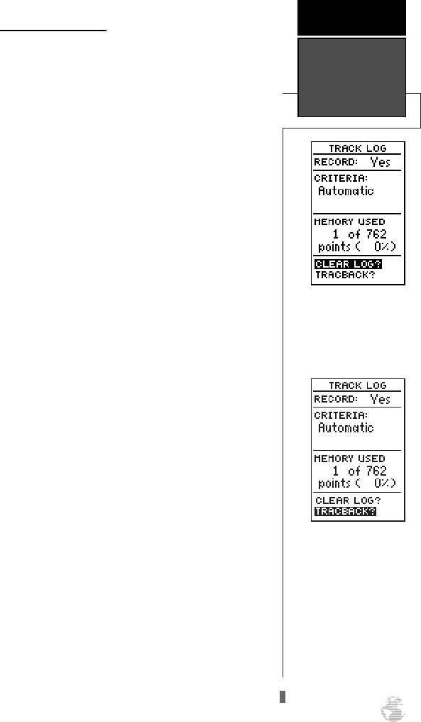
To clear the track log and define a starting point
for a TracBack route:
1. From the Menu Page, highlight ‘TRACK LOG’.
2. Press
F
to access the track log page.
3. Use the
U
key to highlight the ‘CLEAR LOG?’ option.
4. Press
F
. A confirmation page will appear.
5. Use
L
to highlight the ‘Yes?’ prompt and press
F
.
To activate a TracBack route:
1. From the Menu Page, highlight ‘TRACK LOG’ option.
2. Press
F
to access the track log page.
3. Highlight the ‘TRACBACK?’ option and press
F
.
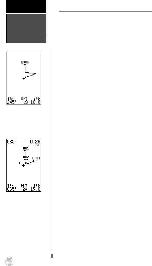
Once the TracBack function has been activated, the
GPS 125 Sounder will take the track log currently
stored in memory and divide it into segments called
legs. Up to 30 temporary waypoints (e.g., ‘T001’) will
be created to mark the most significant features of the
track log in order to duplicate your exact path as close-
ly as possible. A TracBack route from your present
position to the oldest track log point will be created as
an active route (the active route page will appear), and
provide steering guidance to each waypoint back to the
starting point of your track log.
29
Clearing the log before you
get started will define the
position the TracBack func-
tion will return you to.
REFERENCE
TracBack
Navigation
Highlight ‘TRACBACK?’
and press ENTER to begin
TracBack navigation.
125 Man Rev B 7/23/98 11:47 AM Page 29
Tips on Creating and Using the TracBack Feature
The GPS 125 Sounder’s TracBack feature is designed
to help you quickly create and activate a route that fol-
lows your path back to a user-defined starting point. To
get the most out of the TracBack feature, remember the
following tips:
• Always clear your track log at the exact point that
you want to return to ( truck, dock, etc.).
• The ‘RECORD’ option on the track log setup page
must be set to the ‘Yes’ position.
• There must be at least two track log points stored
in memory to create a TracBack route.
• If there are not enough available waypoints in
memory to create a TracBack route, you will be
alerted with a ‘waypoint memory full’ message,
and the receiver will use any available waypoints
to create a TracBack route with an emphasis on
the track log closest to the destination (the oldest
track log point in memory).
• If the ‘CRITERIA’ option on the track log setup
page is set to a time interval, the TracBack route
may not follow your exact path (the ‘Automatic’
setting will provide the best TracBack route).
• If the receiver is turned off or you lose satellite
coverage during your trip, the TracBack route will
simply draw a straight line between any point
where coverage was lost and where it resumed.
• If the changes of direction and distance of your
track log are very complex, 30 waypoints may not
be enough to accurately mark your exact path.
The receiver will then assign the 30 waypoints to
the most significant points of your track.
• If you want to save a TracBack route, copy route 0
to an open storage route before activating another
TracBack. Activating another TracBack or storage
route will overwrite the existing TracBack route.
• Whenever a TracBack route is activated, tempo-
rary waypoints (e.g., ‘T001’) that are not con-
tained in routes 1-19 are erased. If there are tem-
porary waypoints stored in routes 1-19, the
receiver will create any new temporary waypoints
using the first three-digit number available.
TracBack
Navigation
REFERENCE
30
The TracBack feature will
navigate your track log
back to the oldest point in
the receiver’s memory.
The track log will be divided
into segments with tempo-
rary waypoints to create a
route back to the beginning
of the track log.
125 Man Rev B 7/23/98 11:47 AM Page 30
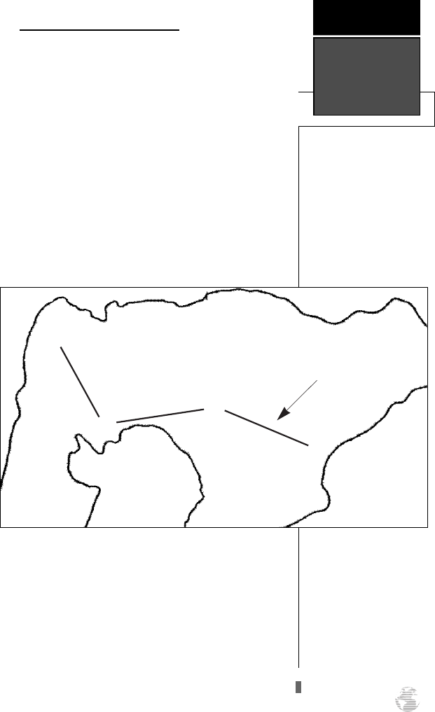
Creating and Navigating Routes
The last form of navigating to a destination with
the GPS 125 Sounder is by creating a user-defined
route. The route navigation feature lets you plan and
navigate a course from one place to another using a set
of pre-defined waypoints. Routes are often used when
it’s not practical, safe, or possible to navigate a direct
course to a particular destination (e.g., through a body
of water or impassable terrain).
Routes are broken down and navigated in smaller
segments called “legs”. The waypoint you are going to
in a leg is called the “active to” waypoint, and the way-
point immediately behind you is called the “active
from” waypoint. The line between the “active to” and
the “active from” waypoint is called the “active leg”.
Whenever you activate a route with the GPS 125
Sounder, it will automatically select the route leg clos-
est to your position as the active leg. As you pass each
waypoint in the route, the receiver will automatically
sequence and select the next waypoint as the “active to”
waypoint.
31
REFERENCE
Route
Navigation
Waypoint 2
(“active to” waypoint)
Waypoint 1
(“active from” waypoint)
“Active Leg”
ä
ä
ä
ä
}
125 Man Rev B 7/23/98 11:48 AM Page 31
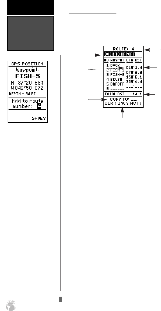
Route Definition Page
The GPS 125 Sounder lets you create and store up
to 20 routes of 30 waypoints each. Routes are created,
copied, and edited through the route definition page,
which is accessed through the Menu Page.
To select the route definition page:
1. Press
J
until the Menu Page appears.
2. Use the
U
and
D
keys to highlight the ‘ROUTES’
option.
3. Press the
F
key to display the route definition
page.
4. To return to the Menu Page, press
J
.
The route number field is displayed at the top of the
page, with a 16-character user comment below. If no
user comment is entered, the field will display the first
and last waypoint in the route. The waypoint list in the
middle of the page accepts up to 30 waypoints for each
route, with fields for desired track and distance between
legs. The total distance of the route is indicated below
the waypoint list.
The bottom of the route definition page features
several function fields which let you copy, clear, invert,
or activate the displayed route. Routes 1-19 are used as
storage routes, with route 0 always serving as the active
route you are navigating. If you want to save a route
currently in route 0, be sure to copy it to another open
route, as it will be overwritten by the next route
activation.
Route Definition
Page
REFERENCE
32
If you’re heading out with-
out a planned route, the
mark function can be used
to quickly create a route
back to your starting point.
Create a series of waypoints
along the way with the
MARK key and save them
to an open route from the
mark position page. When
you’re ready to head back,
simply activate the route
you created in inverted
order (see pg. 34).
Comment
Field
Desired
Track of Leg
Total Route
Distance
Route
Number
Copy Field
Function Prompts
Leg Distance
125 Man Rev B 7/23/98 11:48 AM Page 32
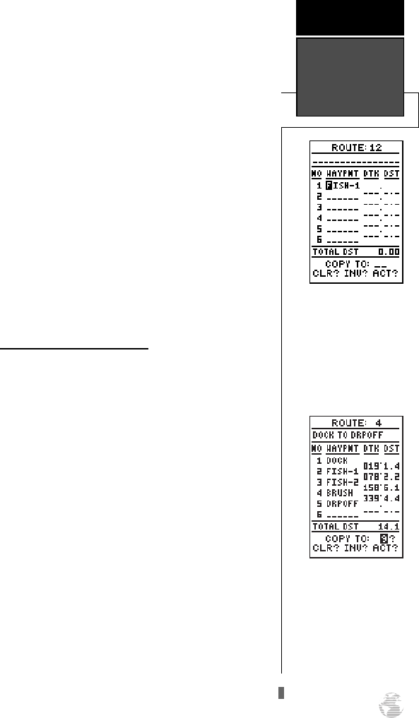
To create a route from the route definition page:
1. Highlight the route number field and press
F
.
2. Enter a route number and press the
F
key to con-
firm.
3. Press
F
to begin entry of a route comment. (Note
that the default [first and last waypoint] comment will
only appear if the comment field is blank.)
4. Enter your comment and press the
F
key.
5. Highlight the No. 1 waypoint field and press
F
.
6. Enter the first waypoint of your route and press
F
.
7. Continue entering the rest of your waypoints in order,
using the
F
key to start and confirm each field
entry. The list will automatically scroll down.
8. After you have entered all your waypoints, press
J
.
Copying and Clearing Routes
The route definition page is also used to copy a
route to another route number. This feature is useful
when you make changes to the active (or TracBack)
route and want to save the route for future use.
To copy a route:
1. Highlight the route number field and press
F
.
2. Enter the route number to be copied and press
F
.
3. Highlight the ‘COPY TO’ field and press
F
.
4. Scroll through the available routes and select a desti-
nation route number. Only open routes will be avail-
able as choices. Press the
F
key to copy the
route.
5. Press the
J
key to return to the Menu Page.
To clear a route from memory:
1. Highlight the route number field and press
F
.
2. Enter the route number and press
F
.
3. Select the ‘CLR?’ prompt and press
F
.
33
Enter each waypoint in the
order you would like to nav-
igate them. If you enter a
waypoint not stored in
memory, you’ll need to
define the position on the
waypoint definition page.
REFERENCE
Creating,
Copying, &
Clearing Routes
To copy a route, select an
open storage route and
press the ENTER key. If you
select a route that is already
used, you’ll be alerted with
a ‘Route Full’ Message.
125 Man Rev B 7/23/98 11:48 AM Page 33
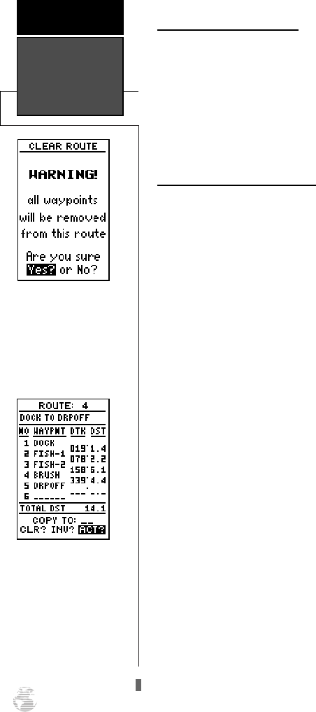
Clearing Routes (continued)
The clear route warning will appear, asking you to
confirm that you want to remove all waypoints from the
route.
1. Highlight the ‘Yes?’ field with the
L
key.
2. Press
F
to confirm your action.
3. Press
J
to return to the Menu Page.
Activating and Inverting Routes
After a route has been entered, it can be activated in
its defined sequence or inverted from the route defini-
tion page. The process of activating or inverting a stored
route takes a storage route (routes 1-19) and copies it
into the active route (route 0) for navigation. The stor-
age route is now no longer needed and will be retained
in its original format under its existing route number.
This system allows you to have an active route that
you may edit during navigation and save as an entirely
new route from the original. You will have to copy the
active route to an unused storage route to save it, since
new route or TracBack activation overwrites route 0.
To activate a route:
1. Select the route definition page and press the
F
key to activate the route number field.
2. Enter the route number to be activated and press
F
.
3. Move the field highlight to the ‘ACT?’ prompt and press
the
F
key.
Inverting a route allows you to navigate route legs in
reverse order without editing the original route.
To activate a route in inverted order:
1. Follow the steps above, but select the ‘INV?’ prompt
and press
F
.
Clearing,
Activating, and
Inverting Routes
REFERENCE
34
Clearing a route only
removes the waypoints from
the route selected. The way-
points used for the route
will still remain in memory
individually.
To activate a route, high-
light the ‘ACT?’ prompt and
press ENTER.
125 Man Rev B 7/23/98 11:48 AM Page 34
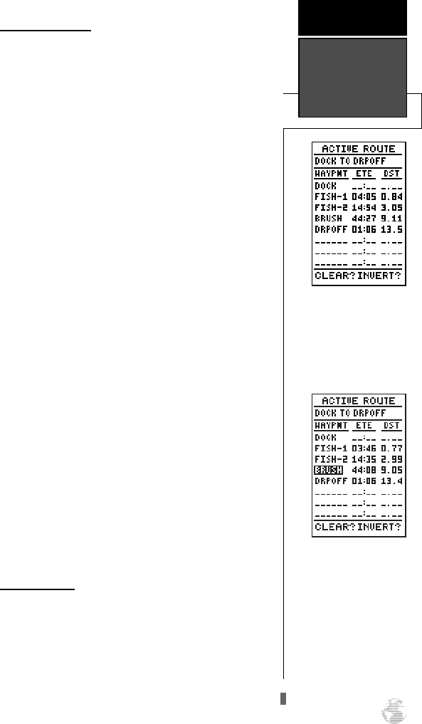
Active Route Page
Once a route has been activated, the active route
page will appear, displaying the waypoint sequence of
your route with the estimated time enroute (ETE) at
your present speed and distance to each waypoint. As
long as you are navigating an active route, the active
route page will become part of the primary page
sequence of the unit.
The active route page will also allow you to change
the ETE field to display desired track (DTK) or estimat-
ed time of arrival (ETA) for each leg. In addition, you
can also clear or invert the active route.
To display DTK or ETA for each leg:
1. Highlight the estimated time enroute (ETE) field and
press the
F
key.
2. Use the
U
or
D
keys to select ‘DTK’ or ‘ETA’ and
press the
F
key.
The active route page also allows you to clear (stop
navigating) or invert the active route without using the
route definition page.
To invert a route from the active route page:
1. Press the
U
key once to move the field highlight to
the ‘INVERT?’ prompt.
2. Press the
F
key to invert the route.
To clear the active route from the active route
page and stop route navigation:
1. Use the
U
and
L
keys to select the ‘CLEAR?’
prompt.
2. Press the
F
key to clear the active route.
Editing Routes
Once a route has been created and stored, it can be
edited at any time, even if it is the active route.
To edit a route from the active route page or the
route definition page:
1. Use the
U
and
D
keys to select the waypoint
you want to edit and press
F
.
35
Whenever you have activat-
ed a route, the active route
page will appear in the pri-
mary page sequence after
the Highway/Compass
Page.
REFERENCE
Active Route
Page
To edit or review a route
waypoints from the active
route page, highlight the
desired waypoint and press
ENTER.
125 Man Rev B 7/23/98 11:48 AM Page 35
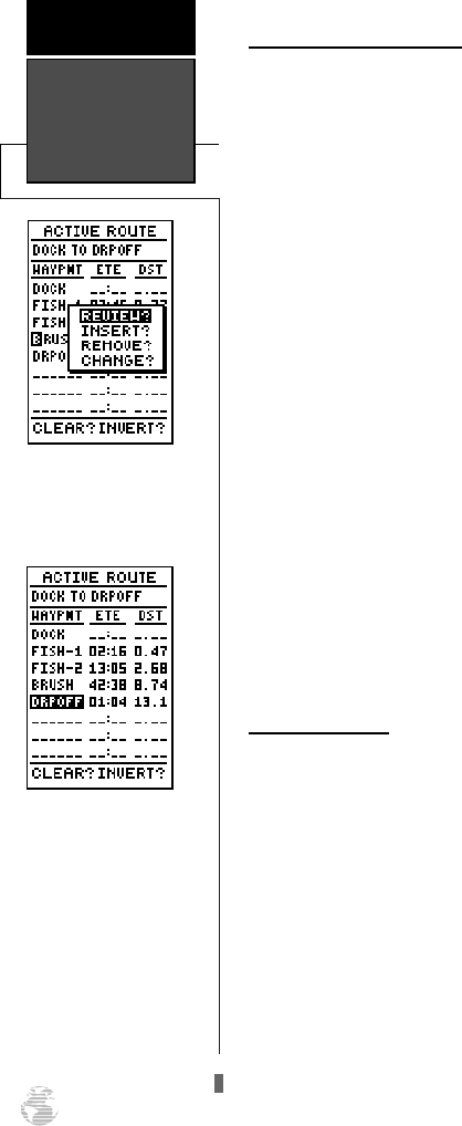
Editing Routes (continued)
An on-screen menu of editing choices will appear,
with options for reviewing, inserting, deleting, or
changing the waypoint field highlighted. Use the
U
and
D
arrow keys to select among the editing choices.
Once you’ve selected a waypoint from the route
list, choose a menu function:
1. To review the definition page for the waypoint, high-
light the ‘REVIEW?’ prompt and press
F
.
2. To add a new waypoint preceding the selected way-
point, highlight the ‘INSERT?’ prompt and press
F
.
3. To remove the selected waypoint, highlight the
‘REMOVE?’ prompt and press the
F
key.
4. To replace the selected waypoint with a new way-
point, highlight the ‘CHANGE?’ prompt and press
F
.
Use the route waypoint editing instructions
described earlier for creating a route to complete your
changes. If you are editing the active route (route 0),
copy your new route version to an empty route to save
it, because the active route will be overwritten by a new
route activation.
If you add, delete, or change the first or last way-
point of a route, the default comment (first and last
waypoint) will automatically be updated.
On-Route GOTOs
At the beginning of this section, we mentioned that
the GPS 125 Sounder will automatically select the route
leg closest to your position as the active leg. This will
give you steering guidance to the desired track of the
active leg. If you would prefer to steer directly to a
route waypoint, you can perform an “on-route GOTO”
from the active route page.
1. Use the
U
and
D
keys to highlight the desired
route waypoint and press the
G
key.
2. Once the GOTO waypoint page appears, press
F
to
confirm.
Note that after you reach the on-route GOTO way-
point, the GPS 125 Sounder will automatically resume
navigating the rest of the route in sequence.
Editing Routes&
On-Route
GOTO’s
REFERENCE
36
Use the on-screen menu to
select the desired editing
function.
You can skip ahead and
navigate to any route way-
point by highlighting the
desired waypoint and press-
ing the GOTO key.
125 Man Rev B 7/23/98 11:48 AM Page 36
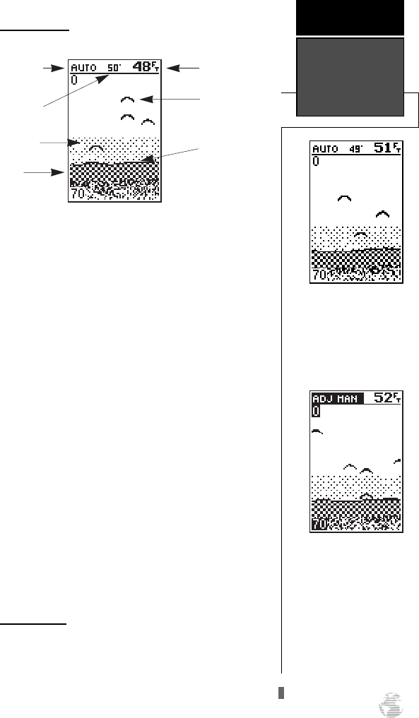
Sounder Page
The Sounder Page lets you use the GPS 125 as a
fishfinder. The top of the screen shows the range mode
being used, the water temperature (if using a tempera-
ture-sensitive transducer), and the digital depth, while
the middle of the page contains a right-to-left moving
sonar image of the water beneath your boat. (Note:
items appear as they pass under your transducer. Those
objects appearing on the right side of the screen are
closer to you than those objects on the left.) Fish are
displayed as a darkened arch or a fish icon in three dif-
ferent sizes. Thermoclines (layers of water separating
warmer water above and cooler water below) appear as
dotted patterns just above the bottom.
The area of strongest sonar return (whiteline) is
displayed as a mix of light and dark checkering.
Typically, the bottom will be the primary source of the
whiteline. A thin whiteline indicates a softer bottom
while a thicker whiteline shows a harder bottom. A
black line is used to show the point where water
meets the whiteline. This black line will follow the bot-
tom contour, along with any significant objects lying
on the bottom. Along the left side of the screen (typi-
cally) is an adjustable scale which shows the current
display’s range of depth.
Range Modes
The GPS 125 Sounder uses two range modes: auto
and manual. ‘Auto’ displays the most information pos-
sible while continuously displaying the bottom.
‘Manual’ lets you select the displayed range. You may
switch between auto and manual modes by using the
arrow keypad or by using the sounder setup menu.
37
GARMIN’s exclusive See-
Thru technology will allow
you to distinguish sonar tar-
gets from bottom clutter and
thermoclines.
REFERENCE
Sounder Page
Overview &
Range Modes
The GPS 125 Sounder uses
Depth Controlled Gain
(DCG) to give you the max-
imum amount of informa-
tion possible with minimal
distortion.
Digital Depth
Sonar Target
Arches
Black Line
Range Mode
Water Temperature
(if equipped)
Thermocline
Whiteline
125 Man Rev B 7/23/98 11:48 AM Page 37
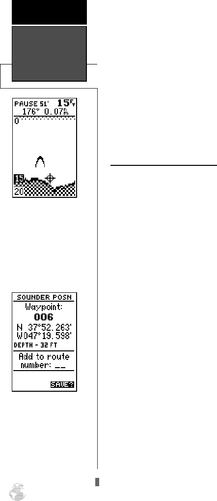
To switch from auto to manual mode:
1. Press the
U
or
D
keys until the desired depth
range is displayed on the depth scale at the left side of
the page.
2. Press
F
to confirm the selected range.
To switch from manual to auto mode:
1. Press the arrow keypad up or down until you hear a
repeated beep. ‘Auto’ will be displayed in the range
field at the top left corner of the screen.
2. Press
F
.
Underwater Waypoint Feature
The underwater waypoint feature marks a way-
point’s position and its depth. This makes it easier to
find and use an object such as a stump for a future fish-
ing location. The target’s depth will be shown on the left
or right side of the screen depending on the location of
the cursor, and will move up and down as the cursor
moves.
To mark an underwater waypoint:
1. Press
F
to pause the screen movement.
2. Use the arrow keypad to activate and move the cursor
onto the desired target (underwater drop off, stump,
etc.). A data field will appear, showing the cursor’s dis-
tance and bearing from your position. Since the dis-
tance and bearing shown are measured from the boat
to the waypoint, they will change as your boat moves,
even if the cursor is stationary.
Note: The cursor will not move off the paused display
and cannot show an area that has scrolled off the
screen.
3. Press
F
. A page will appear with the waypoint’s
coordinates, default three digit name, and depth.
4. Enter any waypoint information such as name, com-
ment, etc., and press
F
. Note: the waypoint’s depth
is the default comment. It is possible for a custom
comment to type over this number.
5. When finished, highlight ‘SAVE?’ and press
F
. The
Sounder Page will reappear.
6. To resume screen movement, press
Q
.
Range Modes &
Underwater
Waypoints
REFERENCE
38
Use the target cursor to
mark the desired underwa-
ter location.
Note: The bearing and
range shown are to the cur-
sor’s location from your pre-
sent position.
The underwater waypoint
will be marked using the
sounder position.
The default comment will
be the cursor’s depth.
125 Man Rev B 7/23/98 11:48 AM Page 38
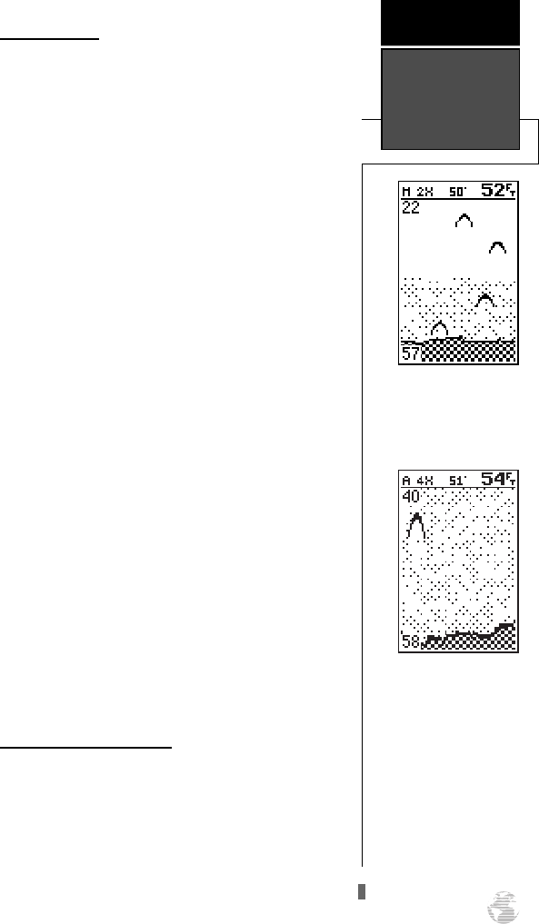
Zoom Function
The sounder zoom function allows you to see the
current display picture at 2 times (2X) or 4 times (4X)
magnification. 2X means that the screen displayed will
now cover 1/2 the range you were originally viewing in
twice the detail, and 4X shows 1/4 the original range at
four times the detail. Because less area is being shown
(in a zoom screen) objects can be seen in greater detail.
The zoom function is accessed by using the IN and
OUT key when viewing the Sounder Page. The sounder
zoom function is divided into two display levels:
• 2X - Displays the zoomed screen at 1/2 the
original range.
• 4X - Displays the zoomed screen at 1/4 the
original range.
Once activated, the zoomed picture becomes the
Sounder Page display. Note: The zoom function can
only be deactivated by pressing the OUT key until the
original zoom scale appears.
The zoom function operates in either Auto range or
Manual range. Zooming while in Auto will continue to
follow the bottom contour, while zooming in Manual
will show the selected depth.
To access the sounder zoom function:
1. While viewing the Sounder Page, press
I
once.
The 2X screen will appear. Note: the current zoom scale
will be displayed in the upper left corner of the screen.
2. Press
I
once more to advance to the 4X screen.
3. To deactivate the sounder zoom function, press
I
once. You may also press and hold
H
until the original
scale picture appears and a triple beep sounds.
Moving the Zoom Window
You may move the displayed range on a zoomed
screen at any time, just as you would a non-zoom
screen, by pressing the arrow keypad up or down. This
will move the zoom “window”.
If you prefer to keep the window in its new posi-
tion, you will need to save the change. Note: Saving the
new window position requires different steps if you are
in Auto range when you move the window versus
being in Manual when the window is moved.
39
Pressing the IN key once
while on the Sounder Page
activates the 2X Zoom.
REFERENCE
Zoom Function
& Zoom
Window
The 4X zoom shows objects
at 4 times magnification
and 1/4 the original range
scale.
125 Man Rev B 7/23/98 11:48 AM Page 39
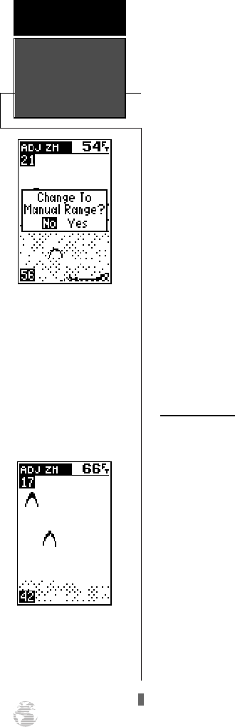
To save a zoom window range in Auto:
1. Press the
R
keypad up to view a shallower range or
down to view a deeper range. The range scale on the
left side of the zoomed picture will be highlighted.
2. When the window reaches the desired range, press
F
to accept. A ‘Change To Manual Range?’ window
will appear. Highlight ‘Yes” and press
F
.
3. If you do not want to save the range, highlight ‘No’ and
press
F
. You may then resume manually moving the
zoom window.
4. Press
Q
at any time to return to an auto range mode
display.
To save a zoom window range in Manual:
1. Press the
R
keypad up to view a shallower range or
down to view a deeper range. The range scale on the
left side of the zoomed picture will be highlighted.
2. When the window reaches the desired range, press
F
to accept.
3. If you do not want to save the range, press
Q
to
return to the previous window range.
Sounder Setup
The sounder displays can be customized to fit your
needs from the sounder setup submenu accessed from
the Menu Page (See pg. 58-61).
Zoom Window
REFERENCE
40
If you activate the zoom
while in Auto range mode
and then decide to manual-
ly adjust the range, a mes-
sage window will appear.
Highlight ‘Yes’ and press
ENTER to activate Manual
range mode and continue
manually adjusting the
range.
The zoom window may be
moved at any time by using
the arrow keypad.
125 Man Rev B 7/23/98 11:48 AM Page 40
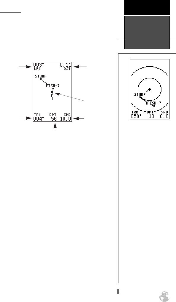
Map Page
The GPS 125 Sounder features a real-time moving
map that can do much more than just plot your course
and route. The Map Page also provides you with a tar-
get cursor that will let you pan ahead to nearby way-
points, determine the distance and bearing to any map
position, and mark new waypoints while you navigate.
The map contains 12 selectable range scales from
0.2 to 320 miles (0.5 to 600 km). The scale represents
the distance shown from the top of the screen to the
bottom. Move from scale to scale by using the dedicat-
ed zoom keys (IN and OUT). Press IN for a smaller
scale map and press OUT for a larger scale map.
A diamond icon in the center of the page represents
your present position, with your track and/or route dis-
played as a solid line. Nearby waypoints are shown as
squares, with the corresponding name listed. You may
select which items are shown through the map setup
submenu page (see pg. 56 for more information).
The four corners of the Map Page are used to dis-
play various navigation data, including the bearing and
distance to a destination waypoint and your current
track and speed over the ground. The two fields at the
top corners of the map show your bearing and distance
to one of three selectable destinations: an active desti-
nation waypoint; a highlighted on-screen waypoint; or
the panning target crosshair. If you are not navigating
to a waypoint or using the panning function, the top
data fields will not be displayed. The bottom corners of
the display always show your current track and speed,
with the digital depth shown in the center.
41
The GPS 125 Sounder has
on-screen range rings to
help you estimate distances
relative to your present
position. The value of each
ring is determined by the
current zoom scale, and is
equal to 1/5 of the selected
scale.
To turn the range rings dis-
play on or off (the default
setting is OFF) see the map
setup instructions on pg. 55-
56.
REFERENCE
Map Page
Bearing to
Waypoint
Track Over
Ground
Speed Over
Ground
Distance to
Waypoint
Present
Position
Digital Depth
125 Man Rev B 7/23/98 11:48 AM Page 41
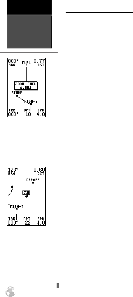
Zooming, Panning, and Pointing
There are three main functions you can perform
from the Map Page: zooming, panning, and pointing.
Zooming is increasing or decreasing the display scale of
the map. Panning is using a target crosshair and the
arrow keypad to “slide” your view of the map in any
direction, including diagonally, to view the surrounding
area. “Pointing” is the act of highlighting a waypoint on
the map in order to find out more about the waypoint
and conduct a GOTO or highlighting a position on the
map to create a new waypoint and conduct a GOTO.
To select a zoom scale (even while panning):
1. Press
I
or
H
once for each level of increase or
decrease desired.
2. Press and hold down either key to increase or
decrease by more than one scale.
To activate the pan function:
1. Press the arrow keypad in any direction, including
diagonally.
As you begin to move the map, a crosshair will
appear. This crosshair will now serve as a target marker
for the moving map. The distance and bearing from
your present position to the target crosshair will appear
in the upper corners of the map. If you are conducting
a GOTO at the time you activate the panning function,
the crosshair bearing and distance will replace the bear-
ing and distance of the GOTO waypoint.
As you pan around the map, you’ll notice that the
target crosshair will point to on-screen waypoints and
highlight the waypoint name. Once a waypoint name is
highlighted, you can review its waypoint definition page
or execute a GOTO right from the Map Page.
To review the definition page for a waypoint high-
lighted on the map:
1. Press
F
. The waypoint definition page will appear.
Review and make any desired changes to the high-
lighted waypoint.
2. When finished, highlight the ‘DONE?’ field and press
F
.
Map Zooming,
Panning, &
Pointing
REFERENCE
42
To change the map scale,
press the IN or OUT key
once for each level desired.
An on-screen window will
display the current zoom
scale.
The crosshair will “snap” to
waypoints highlighted on
the map, which allows you
to quickly review or go to
the selected waypoint right
from the Map Page.
125 Man Rev B 7/23/98 11:48 AM Page 42
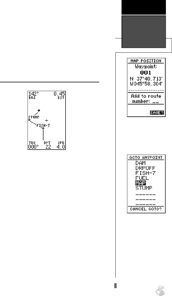
To go to a waypoint highlighted on the map:
1. Press the
G
key. The GOTO waypoint page will
appear with the waypoint’s name highlighted.
2. Press the
F
key to confirm.
To stop the panning function and display your
present position:
1. Press the
Q
key.
Using the Cursor to Mark and Go to Waypoints
During panning, the crosshair represents a target
position right on the moving map, with the range and
bearing to the target displayed at the top corners of the
screen. You can also use the target crosshair to mark a
new waypoint position or as a GOTO destination right
from the map field.
To mark the target crosshair position as a new
waypoint:
1. Press the
F
key to capture the position.
2. Enter a new name and route number and press
F
.
You can also use the target crosshair as an instant
GOTO destination. This function will mark and
instantly set a course for a new waypoint called ‘MAP’.
To GOTO the target crosshair:
1. Press the
G
key to capture the position.
2. Press the
F
key to confirm the MAP GOTO.
To save the MAP waypoint, rename it, as it will be
overwritten the next time a map GOTO is executed.
43
To mark a waypoint with
the crosshair, simply pan to
the desired position and
press the ENTER key.
REFERENCE
Using the
Cursor on the
Map
The crosshair may also be
used to define a GOTO des-
tination by panning to the
desired position and press-
ing the GOTO key. To save
the MAP waypoint, rename
it, as it will be overwritten
by the next MAP waypoint.
125 Man Rev B 7/23/98 11:48 AM Page 43
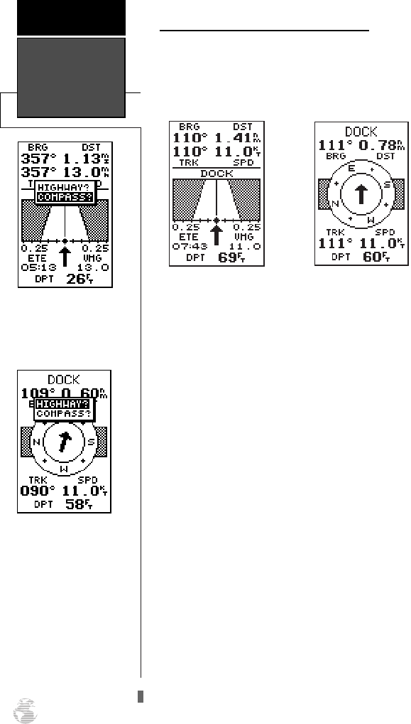
Selecting a User-Defined Navigation Page
Once you’ve selected a GOTO destination or acti-
vated a MOB or route, the GPS 125 Sounder will pro-
vide graphic steering guidance to the destination with
one of two navigation pages:
•The Highway Page (the default navigation page)
provides a graphic highway that shows your move-
ment relative to the desired course, with an
emphasis on your crosstrack error (the distance
and direction you are off course). The Highway
Page is well-suited for boating and other activities
with higher speeds and straight-line courses to a
destination.
•The Compass Page provides a directional pointer
to the destination, with a rotating compass graphic
to display your direction of travel. The Compass
Page is ideal for activities like trawling or entering
a harbor, and provides better steering guidance for
slow-speed (e.g., walking) travel with many direc-
tional changes.
Both pages provide a digital display of the bearing
and distance to the destination, along with your current
speed and track over the ground. Select the desired nav-
igation page at any time.
To select the Compass or Highway Page:
1. Press
J
until the current navigation page appears.
2. Press
F
. An on-screen box will appear, with the
navigation page not currently in use highlighted as the
default.
3. Press
F
to switch the navigation screen.
Highway &
Compass Pages
REFERENCE
44
To switch the navigation
page to the Compass Page,
press ENTER twice.
To switch the navigation
page to the Highway Page,
press ENTER twice.
125 Man Rev B 7/23/98 11:48 AM Page 44
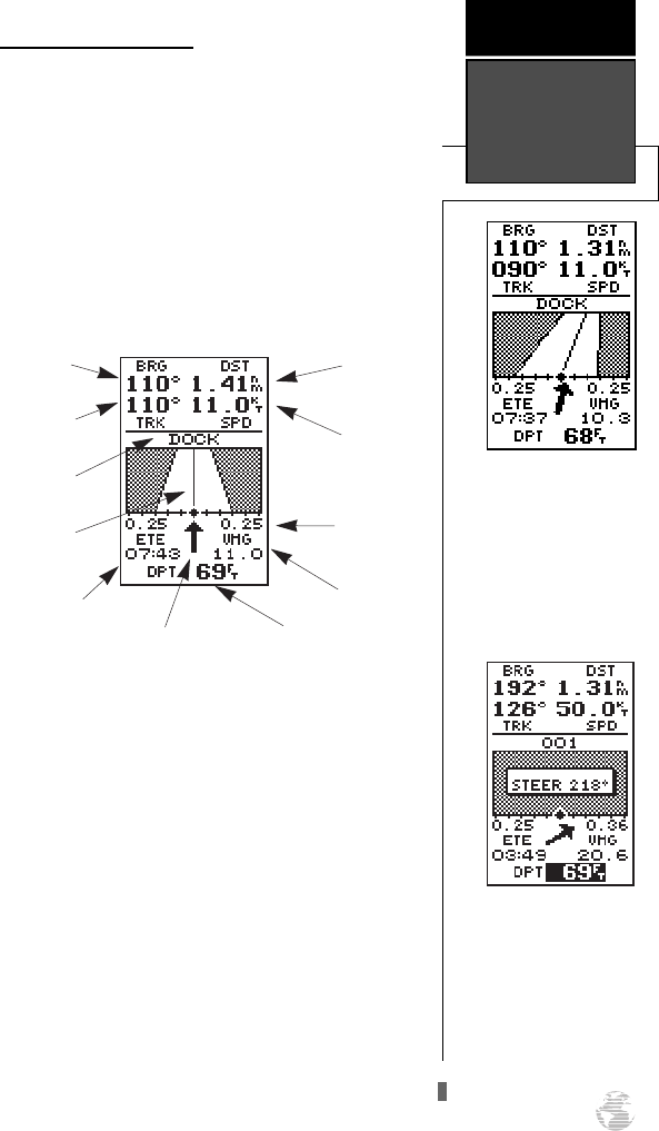
Using the Highway Page
The GPS 125 Sounder’s Highway Page also pro-
vides graphic steering guidance to a destination, with a
greater emphasis on the straight-line desired course
and the distance and direction you are off course. The
bearing and distance to a waypoint--along with your
current track and speed--are displayed at the top of the
screen, with your digital depth, estimated time enroute
(ETE), and velocity made good (VMG, or the rate you
are closing in on your destination), at the bottom.
As you head toward your destination, the middle
section of the screen provides visual guidance to your
waypoint on a moving graphic “highway”.
Your present position is represented by the dia-
mond in the center of the course deviation scale. The
line down the middle of the highway represents your
desired track. As you navigate toward a waypoint, the
highway will actually move and indicate the direction
you are off course, relative to the position diamond on
the CDI scale. To stay on course, simply steer toward
the center of the highway.
If you do get off the desired course by more than
1/5th of the selected CDI range, the distance you are
off course will be displayed where the CDI scale setting
normally appears. If you get too far off course (the
highway has disappeared), a message box will appear
to indicate what course to steer to get back on course.
45
In this example, the
Highway Page indicates
that you are off course to the
left. Steer right to get back
on course. Notice the
emphasis of the Highway
Page is on the desired
course.
REFERENCE
Highway Page
If you get too far off course,
a message box will appear
to indicate what course to
steer to get back on course
most efficiently.
Bearing to
Waypoint
Graphic
Highway
CDI
Distance to
Waypoint
Estimated
Time Enroute
Velocity
Made Good
Speed Over
Ground
Track Over
Ground
Destination
Waypoint
Digital Depth
Pointer to Waypoint
125 Man Rev B 7/23/98 11:48 AM Page 45
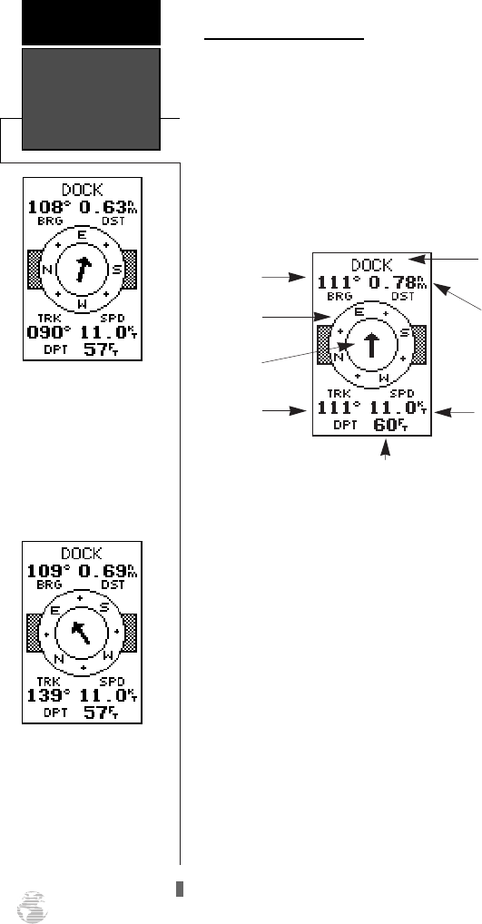
Using the Compass Page
The GPS 125 Sounder’s Compass Page provides
graphic steering guidance to a destination waypoint.
The bearing (BRG) and distance (DST) to the waypoint
are displayed at the top of the page, below the destina-
tion waypoint field. The distance displayed is always the
straight-line distance from your present position to the
destination waypoint. The bearing indicates the exact
compass heading from you to the destination.
The middle of the page features a rotating “compass-
ring ” that shows your current heading while you’re mov-
ing (track up), with a pointer arrow to the destination, dis-
played in the center. The arrow shows the direction of
your destination from the direction you are moving. If the
arrow points up, you are going directly to the waypoint. If
the arrow points any other direction (left, right, down,
etc.), turn toward the arrow until it points up and then
continue in that direction.
The bottom of the Compass Page shows your current
track (TRK), speed (SPD) over the ground, and digital
depth (DPT).
When you are one minute away from the destination
(based on your current speed and track over the ground),
the GPS 125 Sounder will alert you with a flashing on-
screen message box.
Compass Page
REFERENCE
46
In this example, the
Compass Page indicates
that you are traveling in an
east (090 degrees) direction
and the destination way-
point is southeast (108
degrees) of your current
direction of travel.
In this example, the
Compass Page indicates
that you are traveling in a
southeast (139 degrees) and
the destination waypoint is
due east (109 degrees) of
your current direction of
travel.
Bearing to
Waypoint
Pointer to
Waypoint
Speed Over
Ground
Destination
Waypoint
Track Over
Ground
Distance to
Waypoint
Graphic
Compass
Digital Depth
125 Man Rev B 7/23/98 11:48 AM Page 46
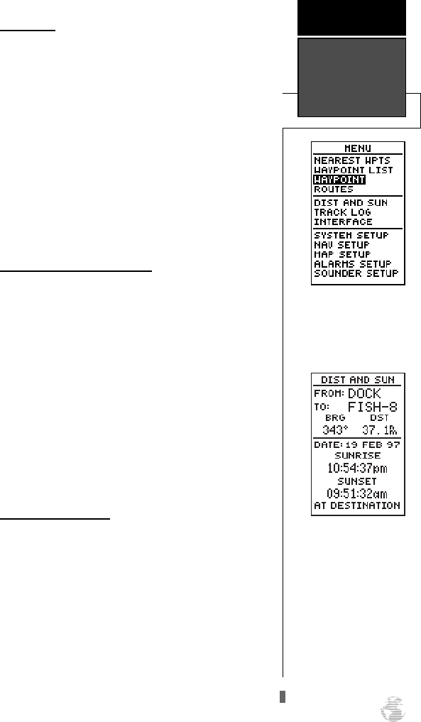
Menu Page
The GPS 125 Sounder Menu Page provides access
to submenu pages used to select and customize opera-
tion and navigation setup. The 11 submenus are divid-
ed into categories by function. See pg. 21-36 for dis-
cussion of waypoint and route management submenus.
We’ll now address the rest of the submenus in the
order they appear on the Menu Page.
To select a submenu page from the Menu Page:
1. Highlight the submenu page you want to view.
2. Press the
F
key to display the submenu page.
3. To return to the Menu Page, press the
Q
key.
Distance and Sun Calculation
The distance and sun calculation page will give you
the distance and bearing between any two waypoints
and will calculate the sunrise and sunset (in local time)
at a destination waypoint for a particular date.
To perform a distance and sun calculation:
1. Highlight the ‘FROM’ field and enter the desired way-
point. Press
F
to move to the next field.
2. Highlight the ‘TO’ field and enter the destination way-
point. Press the
F
key to calculate the range and
bearing to the destination waypoint.
3. Highlight ‘DATE’ and enter the date for your destina-
tion. Press
F
to display the sun information.
Track Log Setup Page
The track log setup page lets you manage the GPS
125 Sounder’s tracking data. From this page, you can
select whether or not to record a track and define how
it is recorded.
To turn the track log on or off:
1. Highlight the ‘RECORD’ field and press
F
.
2. Select ‘Yes’ or ‘No’ and press
F
. NOTE: Turning
the track recording off will prevent using TracBack.
47
To select a submenu, use the
UP and DOWN arrow keys
to highlight a menu option
and press ENTER.
REFERENCE
Menu Page &
Distance/Sun
Calculation
The GPS 125 Sounder will
calculate the sunrise and
sunset times of any stored
waypoint or your present
position. To calculate, enter
the date and year and press
ENTER.
125 Man Rev B 7/23/98 11:48 AM Page 47
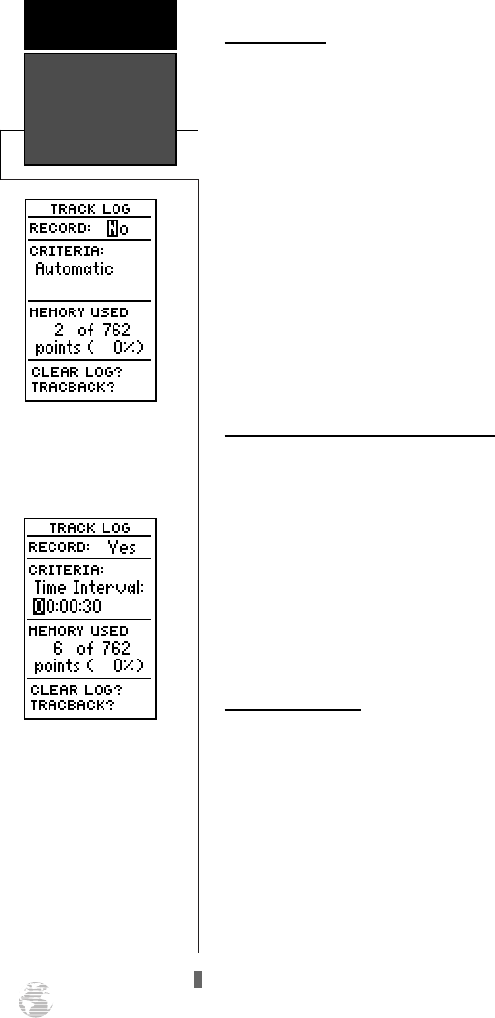
Track Criteria
The stored track criteria determines how often posi-
tions are stored in the track log. The default setting is
automatic, which stores track based on resolution.
‘Automatic’ is the most efficient use of track memory
and provides the most accurate TracBack route.
To change the criteria to record points based
upon a specific time interval:
1. Highlight the ‘CRITERIA’ field and press
F
.
2. Use
U
or
D
to select ‘Time Interval’ and press
F
.
3. Press
F
to begin entry of the interval.
4. Enter a value in hours, minutes and seconds, and
press the
F
key.
Managing and Clearing the Track Log
The rest of the track log setup page displays the per-
centage of available memory currently used to store
track log data and function fields in order to clear the
track log memory and activate the TracBack feature.
To clear the track log:
1. Highlight ‘CLEAR LOG?’ and press
F
.
2. A warning page will appear, and ask you to confirm
your actions. Use the
L
key to move the field highlight
to the ‘Yes?’ field and press
F
.
TracBack Function
The TracBack option lets you activate a TracBack
route using the track log (see pg. 29-30 for more infor-
mation).
To activate a TracBack route:
1. Highlight the ‘TRACBACK?’ option and press
F
.
Track Log Setup
& TracBack
REFERENCE
48
Turning the track recording
option off will prevent you
from using the TracBack
option.
Entering a time interval in
to the track recording crite-
ria will plot your position
points further apart than
they would be in the
‘Automatic’ setting. This
will increase the distance
you can travel without
using up your track log, but
will greatly reduce the effec-
tiveness of TracBack.
125 Man Rev B 7/23/98 11:48 AM Page 48
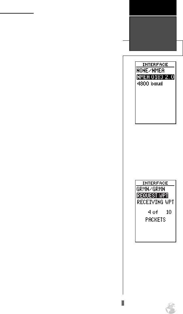
Interface Setup
The interface setup page lets you specify the inter-
facing formats for connecting external devices. There
are five interface options: GRMN/GRMN, None/None,
None/NMEA, RTCM/None, and RTCM/NMEA. Each
option lists the input format first, followed by the out-
put format.
To select I/O format:
1. Highlight the I/O field and press
F
.
2. Use the
U
and
D
keys to toggle through and
select the desired setting, and press
F
.
The GRMN/GRMN setting is a proprietary format
that lets you exchange information such as waypoints,
routes and track logs between two GARMIN GPS
devices or a PC. During data transfer, the number of
packets being exchanged will be displayed on screen.
To select a transfer option:
1. Highlight the ‘HOST’ field and press
F
.
2. Use
U
and
D
to select a setting and press
F
.
To disable all interfacing capabilities, select the
None/None setting. If you want to output NMEA data
to compatible external devices without any differential
input capability, select the None/NMEA setting. Once a
NMEA output setting has been selected (with or with-
out RTCM input), the NMEA field will become high-
lighted. NMEA formats 0180, 0182 or 0183 (1.5 or
2.0) are available.
To select a NMEA format:
1. Press
F
to begin a NMEA selection.
2. Use
U
and
D
to select a format, and press
F
.
49
A field for additional infor-
mation will be displayed
when required for the select-
ed interface option. Above,
the None/NMEA option will
allow input of NMEA ver-
sions and a baud rate.
REFERENCE
Interface
Options
Choose a ‘HOST’ field
based upon the type of
information transfer you
want to occur between the
two interfacing devices.
125 Man Rev B 7/23/98 11:48 AM Page 49
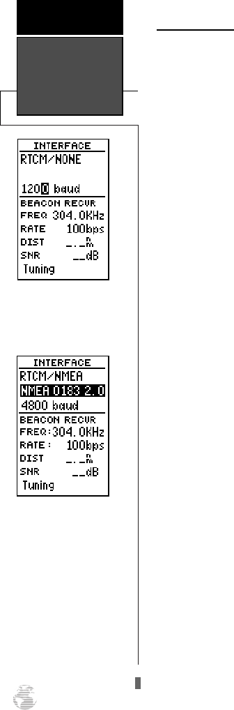
DGPS Interface
The last two format settings allow the differential-
ready GPS 125 Sounder to accept RTCM DGPS correc-
tions in RTCM 104 version 2.0 format. Using DGPS
corrections will improve receiver accuracy to 5-10
meters, regardless of errors induced by the government’s
Selective Availability (SA) program. The RTCM/NONE
format will allow connection to any manually tuned
beacon receiver by using the proper output interface.
The baud rate is selectable from the GPS 125 Sounder.
The RTCM/NMEA selection controls the GARMIN
GBR-21 differential beacon receiver. Once a RTCM set-
ting has been selected, the GPS 125 Sounder will either
automatically try to tune the last frequency and bit rate
you selected or will switch to the default frequency of
304.0 kHz with a bit rate of 100 bps if no previous bea-
con has been tuned. You may also enter your own fre-
quency and bit rate if desired.
To enter a DGPS beacon frequency:
1. Highlight the ‘FREQ’ field and press
F
.
2. Enter the desired frequency and press
F
.
3. Highlight the ‘RATE’ field and press
F
.
4. Use
U
and
D
to select the desired transmit rate.
5. Press the
F
key to confirm your entry.
When the GPS 125 Sounder is receiving DGPS cor-
rections from the GBR-21, the ‘BEACON RECVR’ sec-
tion of the I/O setup page will display the beacon fre-
quency and signal strength, as well as the distance from
the transmitter to the beacon receiver. At the bottom of
the beacon receiver field, a status message will keep you
informed of DGPS activity:
• A ‘Tuning’ message will be displayed while a bea-
con signal is being tuned.
• Once the beacon signal has been tuned, a
‘Receiving’ message will be displayed.
• If a beacon signal is tuned and no corrections are
being received, a ‘No Data’ message will be dis-
played.
• If a beacon signal cannot be tuned, a ‘No Status’
message will be displayed.
DGPS Interface
REFERENCE
50
The selectable baud rate is
available for all RTCM
interface options.
Once a RTCM option is
selected, you must manual-
ly tune the beacon receiver
from the frequency field.
125 Man Rev B 7/23/98 11:48 AM Page 50
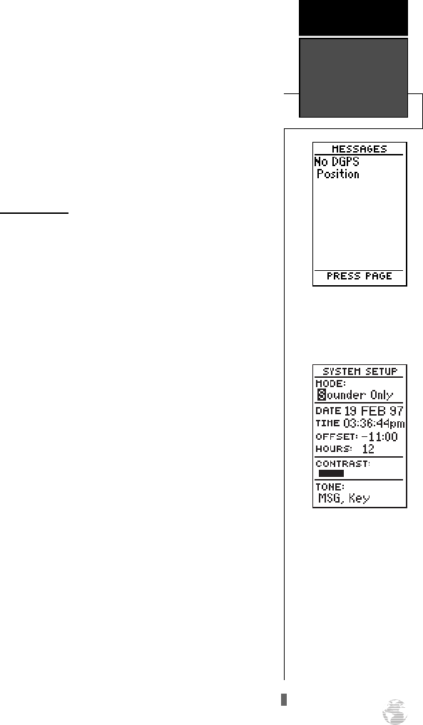
The GPS 125 Sounder will also display one of three
alert messages concerning DGPS operation through the
message page:
No DGPS Position— not enough data is available
to compute a DGPS position.
No RTCM Input— the beacon receiver is not
properly connected or the baud rates do not
match.
RTCM Input Failed— DGPS data was being
received but has been lost.
System Setup
The first setup page is the system setup page,
which is used to select the operating mode, time offset
and screen preferences. The GPS 125 Sounder has four
operating modes:
• ’Normal’ Mode is the mode used for actual
navigation. Satellite data is acquired and used in
figuring and displaying your position and
movement.
• ’Simulator’ Mode allows you to operate the unit
without acquiring satellites, and is ideal for prac-
ticing or entering waypoints and routes while at
home.
• ’GPS Only’ Mode does not display any informa-
tion on the Sounder Page. This is useful when
using the unit for land navigation while enroute
to the water.
• ’Sounder Only’ Mode will not display GPS
information (such as position, speed, heading,
and map functions).
To select an operating mode:
1. Highlight the ‘MODE’ field and press
F
.
2. Use the arrow keypad to select a mode and press
F
.
51
Alert messages will signal
any problems with DGPS
operation.
REFERENCE
DGPS Interface
& System Setup
The GPS 125 Sounders four
operating modes are
accessed through the system
setup submenu.
125 Man Rev B 7/23/98 11:48 AM Page 51
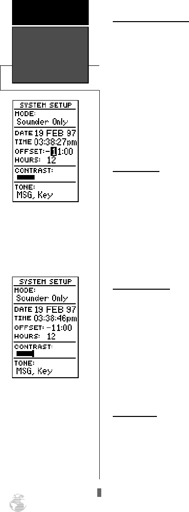
Date and Time Setup
The date and time field is located directly below the
mode field. Because the time shown is UTC time, you
will need to enter a time offset to display the correct
local time for your area. To determine the time offset for
your area, note your position and refer to the chart in
Appendix C.
To enter the time offset:
1. Highlight the ‘OFFSET’ field and press the
F
key.
2. Enter the time offset and press
F
. Remember to
select a positive or negative indicator for your offset.
Time Format
The time display shown on the system setup and
Position Pages may be set to display the time in a 12 or
24-hour format.
To select the time format:
1. Highlight the ‘HOURS’ field and press the
F
key.
2. Select 12-or 24-hour display, and press
F
to
confirm.
Screen Contrast
The GPS 125 Sounder has adjustable screen con-
trast that is controlled by using an on-screen bar scale.
To set the screen contrast:
1. Move the field highlight to the ‘CONTRAST’ field and
press the
F
key.
2. Use the
L
and
R
keys to adjust the bar scale for the
desired contrast and press the
F
key.
Tone Setting
You may choose from three settings for audible
tone: messages only, messages and keystrokes, or no
tone at all.
To specify a tone setting:
1. Highlight the ‘TONE’ field and press the
F
key.
2. Use the
U
and
D
keys to select the desired tone
and press
F
.
Setting Time,
Screen Contrast,
& Tone
REFERENCE
52
To display the correct local
time, you must enter the
appropriate offset from the
chart at the end of
Appendix C.
Screen contrast may be
adjusted with the contrast
bar.
125 Man Rev B 7/23/98 11:48 AM Page 52
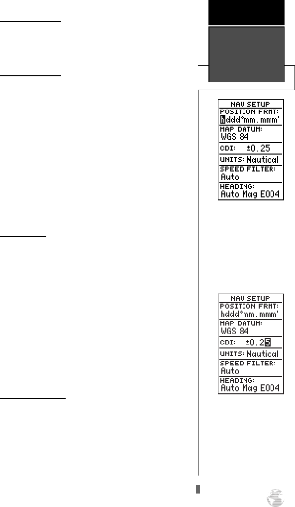
Navigation Setup
The navigation setup page is used to select units of
measurement for position format, map datum, CDI
scale, and distance, speed, and heading information.
Position Formats
The default position setting for the GPS 125
Sounder is latitude and longitude in degrees and min-
utes (hdddºmm.mmm’). You may also select degrees,
minutes and seconds (hdddºmm’ss.s’’); degrees only
(hddd.dddddº); UTM/UPS coordinates; or British,
German, Irish, Maidenhead, Swedish, Swiss, or Taiwan
grid formats.
To select a position format:
1. Highlight the ‘POSITION FRMT’ field and press
F
.
2. Use the
U
and
D
keys to select the desired set-
ting. Confirm the setting by pressing
F
.
Map Datums
The map datum field is located just below the posi-
tion format field, and comes with a WGS 84 default
setting. Although 104 total map datums are available
for use (see the map datum listing in Appendix D), you
should only change the datum if you are using maps or
charts that specify a different datum than WGS 84.
To select a map datum:
1. Highlight the ‘MAP DATUM’ field and press
F
.
2. Use the
U
and
D
keys to toggle through and
select the desired setting. Confirm the setting by
pressing
F
.
CDI Scale Settings
The course deviation indicator (CDI) scale defini-
tion field lets you select the +/- range of the CDI bar
scale. Three scales are available: +/- 0.25, 1.25 and 5.0
miles or kilometers, with 0.25 being the default setting.
To enter a CDI scale setting:
1. Highlight the ‘CDI SCALE’ field and press
F
.
2. Use
U
and
D
to select the desired setting and
press
F
.
53
The position format may be
set to display your choice of
many formats. Note: degree
and minutes is the default
setting.
REFERENCE
Navigation
Setup
Adjusting the CDI Scale will
determine the value used in
the Highway Page and for
the range rings on the Map
Page (if displayed).
125 Man Rev B 7/23/98 11:48 AM Page 53
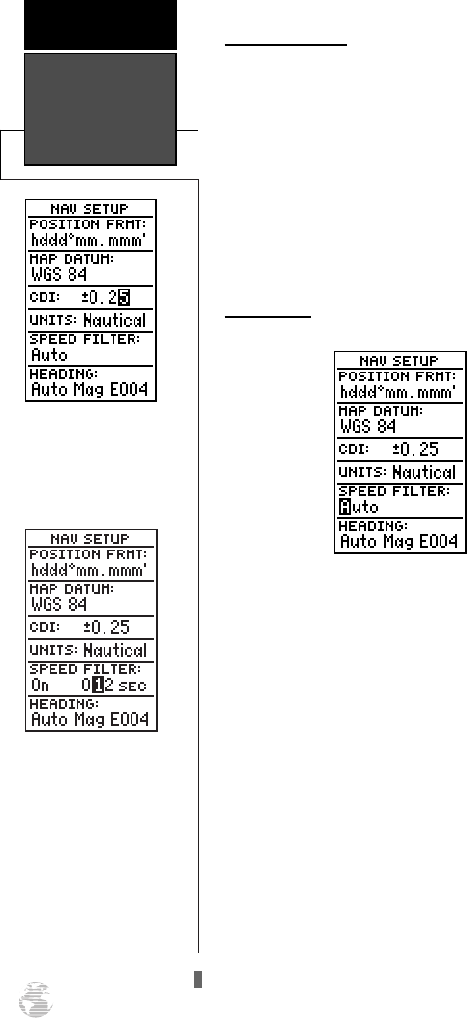
Units of Measure
The GPS 125 Sounder lets you select nautical
(default), statute, or metric units of measure for all
speed and distance fields.
To change the unit of measure:
1. Highlight the ‘UNITS’ field and press the
F
key.
2. Use
U
and
D
to select the desired unit of
measure.
3. Press the
F
key to confirm the selection.
Speed Filter
The speed filter allows you to determine how the
GPS 125 Sounder responds to changes in track or
ground speed. Three settings are available: Auto, On, or
Off. The ‘Auto’ setting is the default and will monitor
the changes in your current track and speed and adjust
the receiver’s response time automatically. The ‘On’ set-
ting allows you to manually enter a response time up to
300 seconds. Selecting a higher setting may be desirable
in slow-speed applications with frequent changes in
track.
To enter a value for the speed filter:
1. Highlight the ‘SPEED FILTER’ field and press
F
.
2. Select the ‘ON’ option and press
F
.
3. Highlight the “speed value” field and press
F
.
4. Select the desired number of seconds and press
F
.
Navigation &
Speed Filter
REFERENCE
54
Choose a navigation unit
you are familiar with or
that may be appropriate to
the situation in which the
GPS 125 Sounder is used.
The number entered repre-
sents a window of time the
GPS 125 Sounder considers
in adjusting to changes in
speed and track. For exam-
ple, if 12 seconds is entered,
the speed displayed will
constantly represent the
speed averaged over the last
12 seconds.
125 Man Rev B 7/23/98 11:48 AM Page 54
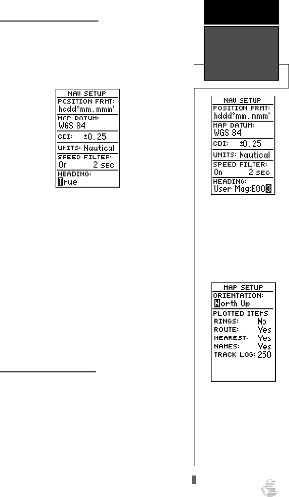
Magnetic Heading Reference
The GPS 125 Sounder’s heading information can be
displayed referencing magnetic north (auto or user-
defined), true north, or calculated grid headings. The
default setting is automatic magnetic north, which is
suitable for most applications.
To select a heading reference:
1. Highlight the ‘HEADING’ field and press
F
.
2. Select the desired heading preference.
3. Press the
F
key to confirm the selection.
To enter a user-defined magnetic heading
:
. 1. Select the ‘USER MAG’ option and press
F
.
2. Use the
U
and
D
keys to enter the degrees
and direction of magnetic variation.
3. Press the
F
key to confirm the magnetic
variation value.
Map Setup and Orientation
The map setup page lets you select map orientation
and specify what items are displayed. The map may be
oriented to north up, the direction of current travel
(track up) or the direction of an active route leg
(desired track up). The default setting is track up.
To change the map orientation:
1. Highlight the ‘ORIENTATION’ field and press
F
.
2. Use the
U
and
D
keys to toggle through and
select the desired setting, and press
F
.
55
The ‘North Up” orientation
causes the top-center of the
Map Page to represent
000º, the right-center to be
090º, the bottom-center
180º, and the left-center to
be 270º.
REFERENCE
Magnetic
Heading & Map
Setup
To enter a user-defined
magnetic variation, select
the ‘User Mag’ option and
enter the desired direction
and value.
125 Man Rev B 7/23/98 11:48 AM Page 55
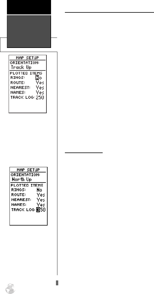
Selecting Displayed Items on the Map Page
The rest of the map setup page lets you specify what
items are displayed or plotted on the Map Page. The
first four plot items may be turned on or off by selecting
‘Yes’ or ‘No’ in the appropriate field:
• The ‘RINGS’ selection will display the three pre-
sent position range rings on the map.
• The ‘ROUTE’ selection will plot the straight leg
lines between waypoints of an active route and
display all route waypoint names.
• The ‘NEAREST’ selection will show the nine near-
est waypoints to your present position (not the
target crosshair on the map).
• The ‘NAMES’ selection will display the waypoint
name for the nine nearest waypoints.
To turn a plotted item on or off:
1. Highlight the confirmation (Yes or No) field for the plot-
ted item and press
F
. Make your desired selection
and press
F
.
Track Log Display
The track log option sets the number of points the
unit will attempt to display on the Map Page. The
default setting of 250 points provides good resolution
with minimal screen clutter. The maximum setting is
768 points. Once you’ve reached the maximum number
of track points, the older points will be lost as new
points are added. Adjusting the track points displayed
will not affect whether or not the receiver records a
track log or the ability to create a TracBack route.
To enter a log setting:
1. Highlight to the ‘TRACK LOG’ field and press
F
.
2. Enter a value in the 3-digit field and press
F
. If you
do not want to display a track, enter ‘000’.
Map Setup
REFERENCE
56
A higher track log value will
make a more detailed track
log but will take up more
memory.
On-screen range rings will
appear on the map when
the ‘RINGS’ option is set to
the ‘Yes’ position.
125 Man Rev B 7/23/98 11:48 AM Page 56
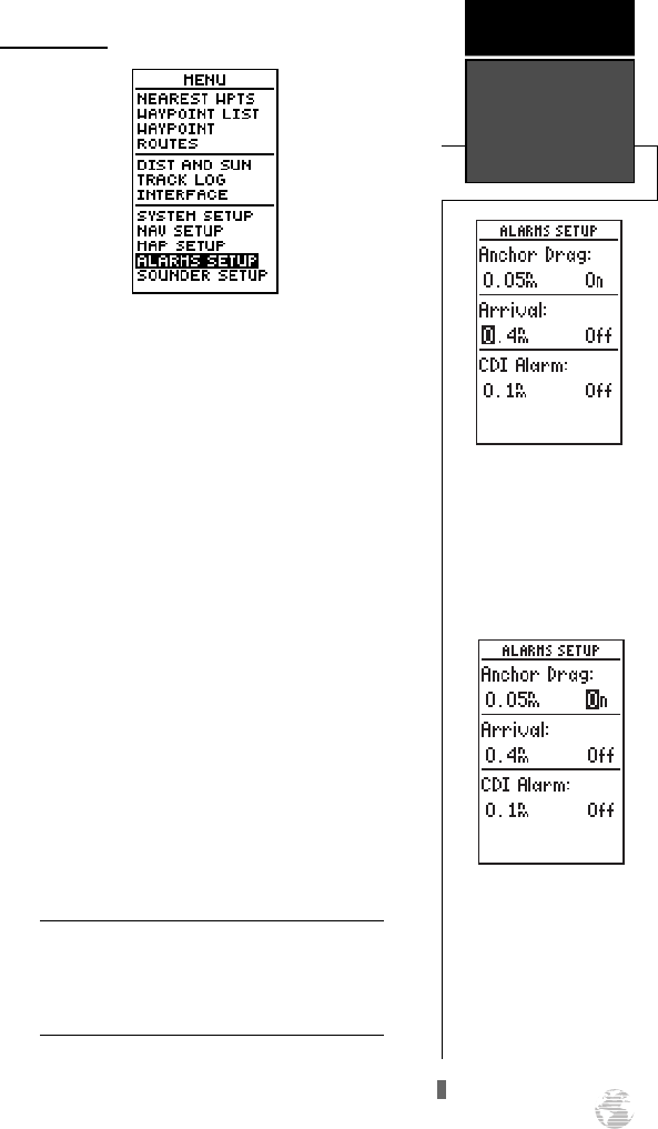
Alarms Setup
The GPS 125 Sounder’s alarms setup page is used
to set the three available alarms: the anchor drag alarm,
arrival alarm, and CDI alarm.
The anchor drag alarm will sound if your boat has
moved outside a range measured from a central point
(your position). The arrival alarm sounds when you are
approaching a waypoint and have reached the user-
defined distance. The CDI alarm will alert you when
your track varies from the shortest distance to a way-
point by the defined range.
To set the alarms:
1. Highlight ‘ALARMS SETUP’ and press
F
.
2. Select the desired alarm distance field and press
F
.
3. Enter the distance for the alarm and press
F
.
4. If you would like to change the ‘On/Off’ setting, press
the
F
key and use the
U
or
D
keys to turn
the alarm on or off.
5. Enter a setting and and press
F
.
When setting the anchor drag alarm, remem-
ber that Selective Availability can degrade
your GPS position as much as 100 meters and
may cause false anchor drag alerts.
57
REFERENCE
Alarms Setup
!
#
The arrival alarm will
sound at the determined
distance from the destina-
tion waypoint.
Use the anchor drag alarm
as an indicator of move-
ment due to possible anchor
slippage.
125 Man Rev B 7/23/98 11:48 AM Page 57
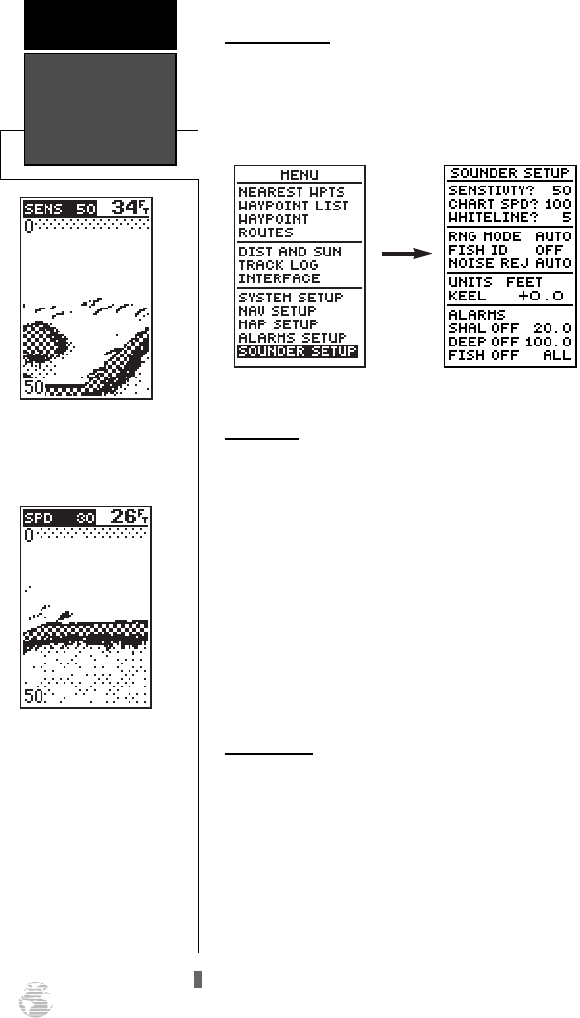
Sounder Setup
The sounder setup page lets you customize the
sounder to your needs and activate certain alarms.
Access the Sounder Setup from the Menu Page.
Sensitivity
The sensitivity setting determines how sensitive the
sounder is to sonar echoes. High sensitivity may show
clutter which can conceal fish, while low sensitivity may
not show all fish. Note: A setting of 50% will give you
the best results for most fishing situations.
To adjust sensitivity:
1. Highlight ‘SENSITIVITY?’ and press
F
. The Sounder
Page will appear with ‘SENS’ and a value displayed in
the upper left corner of the page.
2. Press the arrow keypad up or down until the desired
sensitivity level is shown and press
F
.
Chart Speed
The chart speed field allows you to select the speed
at which the sonar display scrolls across the screen.
To adjust chart speed:
1. Highlight ‘CHART SPD?’ and press
F
. The Sounder
Page will appear with ‘SPD’ and a value displayed in
the upper left corner of the page.
2. Press the arrow keypad up or down until the desired
chart speed is shown and press
F
.
Sounder Setup
REFERENCE
58
Adjust the sensitivity range
between 0 and 100. The
default setting is 50.
The chart speed may be
adjusted between 10 (slow-
est) and 100. The default is
100.
125 Man Rev B 7/23/98 11:48 AM Page 58
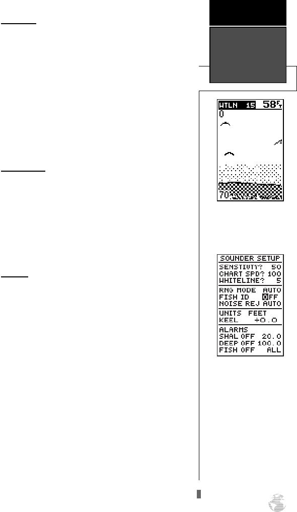
59
Whiteline
You may select how the area of strongest sonar
return is shown through the whiteline setting. A high
setting will cause a thick whiteline while low settings
show a thin whiteline.
To adjust the whiteline:
1. Highlight ‘WHITELINE?’ and press
F
. The Sounder
Page will appear with ‘WTLN’ and a value displayed
in the upper-left corner of the page.
2. Press the arrow keypad up or down until the desired
whiteline level is shown and press
F
.
Range Mode
You may select the range mode from this menu.
To select the auto or manual range mode:
1. Highlight the ‘RNG MODE’ field and press
F
. The
Manual/Auto field will be highlighted.
2. Press the arrow keypad up or down until the desired
range mode is shown and press
F
.
Fish ID
The Fish ID setting determines how the GPS 125
Sounder identifies and labels sonar targets on the
screen. Three settings are available:
• OFF - is the default setting and shows all sonar
target information in its unprocessed form.
• ON - shows small, medium, and large fish icons,
along with each target’s depth. Other echo informa-
tion (thermoclines, thin stumps, etc.) is shown as a
dotted pattern.
• FISH - shows fish icons and depth and does not
show other echo information.
To select Fish ID:
1. Highlight the ‘FISH ID’ field and press
F
. ‘ON/OFF’
will be highlighted.
2. Select the desired setting and press
F
.
REFERENCE
Whiteline &
Fish ID
The whiteline may be
adjusted from 0 (off) to 100.
The default setting is 5.
The ‘OFF’ setting is the Fish
ID default and will show
sonar targets as arches.
125 Man Rev B 7/23/98 11:48 AM Page 59
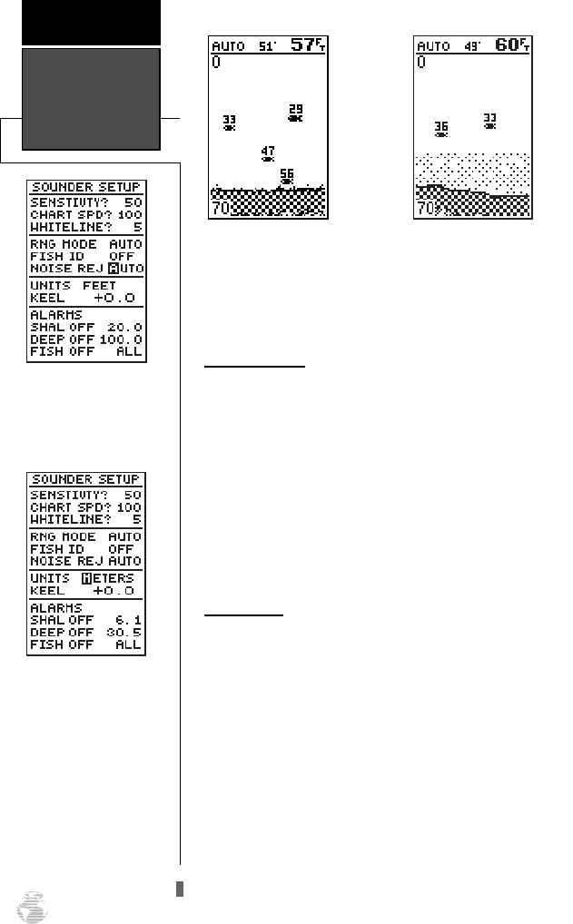
60
The above examples illustrate the difference
between having Fish ID set to “FISH” versus “ON”. The
most information is available with the “ON” setting.
Noise Rejection
The noise rejection setting determines how much
the unit screens out electronic interference from nearby
equipment. The “Auto” setting is the default and will
turn noise rejection on and off as needed.
To set noise rejection:
1. Highlight the ‘NOISE REJ’ field and press
F
. The
AUTO/ON/OFF field will be highlighted.
2. Press the arrow keypad up or down until the desired
mode is shown and press
F
.
Depth Units
The depth units field allows you to determine
whether sounder depth is displayed in feet, meters, or
fathoms.
To set the depth units:
1. Highlight ‘UNITS’ and press
F
. The
‘FEET/METERS/FATHOM’ field will be highlighted.
2. Press the arrow keypad up or down until the desired
depth unit is shown and press
F
.
Noise Rejection
& Depth Units
REFERENCE
ID Setting - FISH ID Setting - ON
Use the noise rejection fea-
ture to minimize interfer-
ence from nearby
electronics.
Choose a desired unit of
measurement from feet,
meters, or fathoms.
125 Man Rev B 7/23/98 11:48 AM Page 60
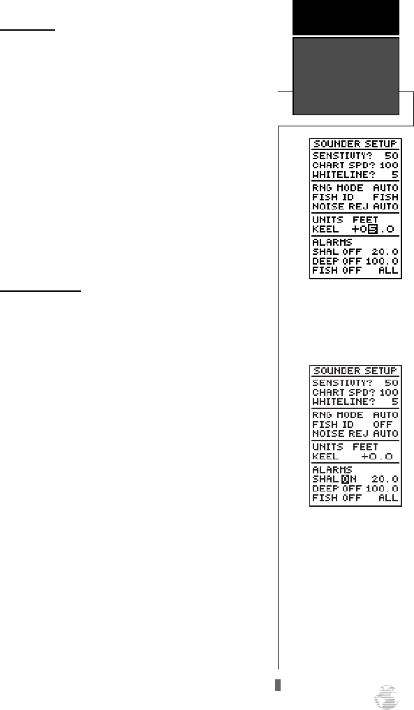
Keel Offset
This setting allows you to set the point from which
the GPS 125 Sounder will measure depth. This makes
it possible to measure depth from the bottom of the
keel instead of from the transducer’s location. A posi-
tive number will measure depth from a deeper point
while a negative number reflects a shallower point.
To set keel offset:
1. Highlight the ‘KEEL’ field and press
F
. The value
field will be highlighted.
2. Select plus (+) or minus (-) and press
F
. The high-
light will move to the value field.
3. Enter the desired offset value using the arrow keypad
and press
F
.
Sounder Alarms
This field allows you to set shallow and deep depth
alarms and an alarm for specific-sized fish/targets Three
options are available:
• Shallow water - Has an on/off setting and a depth
value field
• Deep water - Has an on/off setting and a depth
value field
• Fish - Has an on/off setting and a
medium/large/all size field
To set a sounder alarm:
1. Highlight the desired alarm and press
F
. The on/off
setting will be highlighted.
2. Use the arrow keypad to select ‘ON’ or ‘OFF’ and
press
F
. The highlight will move to the value field.
3. Enter the desired value using the arrow keypad and
press
F
.
61
REFERENCE
Keel Offset &
Sounder Alarms
The alarms can be set to
activate at a specified shal-
low and deep water depth
and when any sonar targets
appear.
Use the keel offset to cus-
tomize the point used to
measure depth.
125 Man Rev B 7/23/98 11:48 AM Page 61
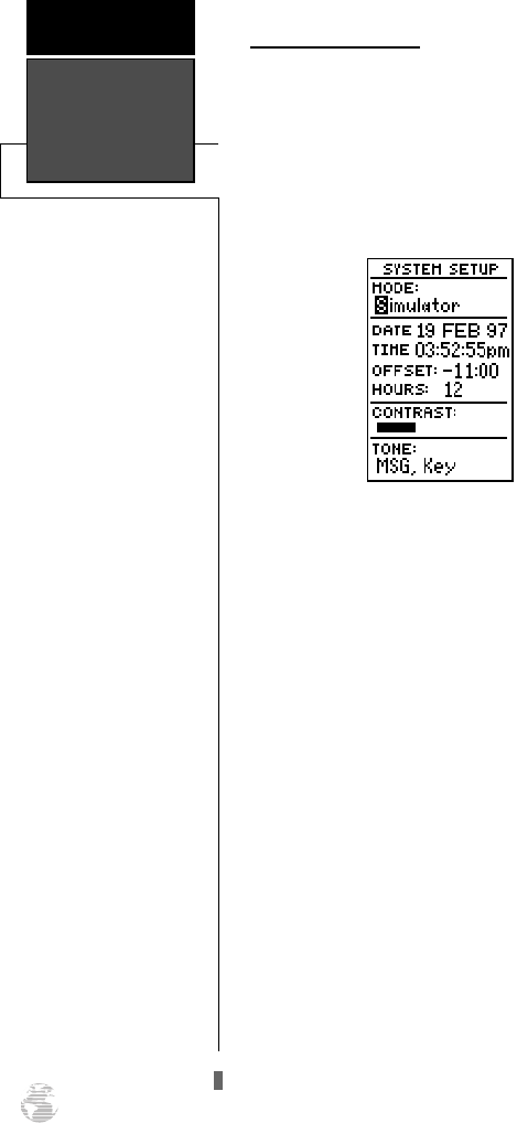
Nav Simulator
REFERENCE
62
Navigation Simulator
The GPS 125 Sounder’s simulator mode lets you
practice all aspects of operation without actually track-
ing satellites. You can also plan and practice trips, enter
new waypoints and routes, and save them for use dur-
ing normal operation. The simulator is activated from
the system setup page, with speed and heading con-
trolled from the Position, Compass, or Highway Pages.
To activate the simulator:
1. Highlight ‘SYSTEM SETUP’ and press
F
.
2. Highlight the ‘MODE’ field and press
F
.
3. Use
U
or
D
to select the simulator mode.
4. Press the
F
key to confirm.
5. Press
F
to return to the Menu Page.
125 Man Rev B 7/23/98 11:48 AM Page 62
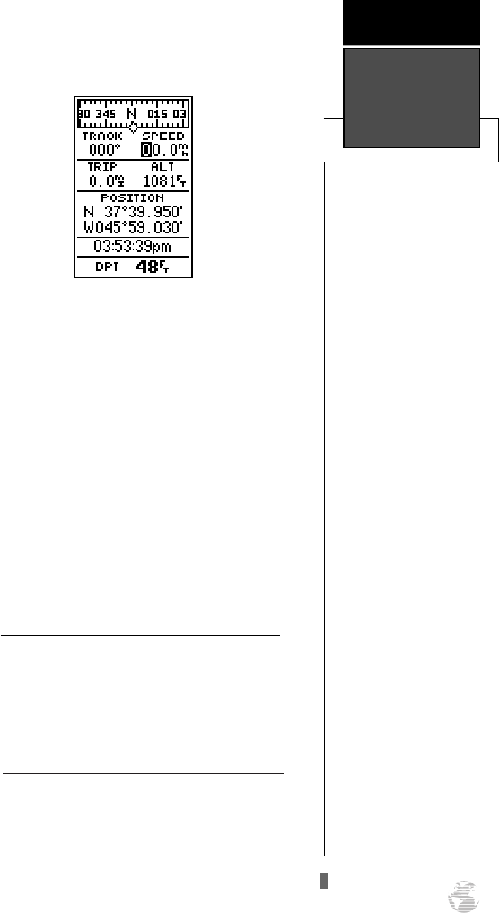
63
REFERENCE
Nav Simulator
Once the simulator mode has been activated, use
the Position, Compass, or Highway Page to set your
speed, track and simulated depth.
To enter track, speed, position, and depth:
1. Highlight the ‘TRACK’ field and press the
F
key.
2. Enter a track and press
F
.
3. Highlight the ‘SPEED’ field and press
F
.
4. Enter a speed and press
F
.
5. Highlight the ‘POS’ field and press
F
.
6. Enter a position and press the
F
key.
7. Highlight the ‘DPT’ field and press
F
.
8. Enter a depth and press the
F
key.
The GPS 125 Sounder does not track satellites
or receive sonar signals in simulator mode.
Although you can create and save waypoints
and routes while using the simulator mode,
never attempt to use the simulator mode for
actual navigation or fishing/depth sounding.
!
#
125 Man Rev B 7/23/98 11:48 AM Page 63
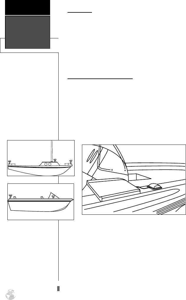
64
Installation
The GPS 125 Sounder must be properly installed
according to the following instructions to get the best
possible performance.
To begin installation, you’ll need to select a suitable
mounting position for the antenna, unit and transducer
(see right). Once you’ve identified the best mounting
location, install the antenna, transducer, and cable first,
and then the unit and wiring harness.
Choosing an Antenna Location
The antenna should be mounted in a location that
has a clear, unobstructed view of the sky in all direc-
tions to ensure the best reception in all conditions.
Avoid mounting the antenna where it will be shaded by
the boat’s superstructure, a radome antenna, or mast.
Most marine VHF and loran antennas will not seriously
degrade the GPS antenna’s reception. Never paint the
antenna or clean it with harsh solvents.
APPENDIX A
Installation
Typical Bass Boat Installation
125 Man Rev B 7/23/98 11:48 AM Page 64
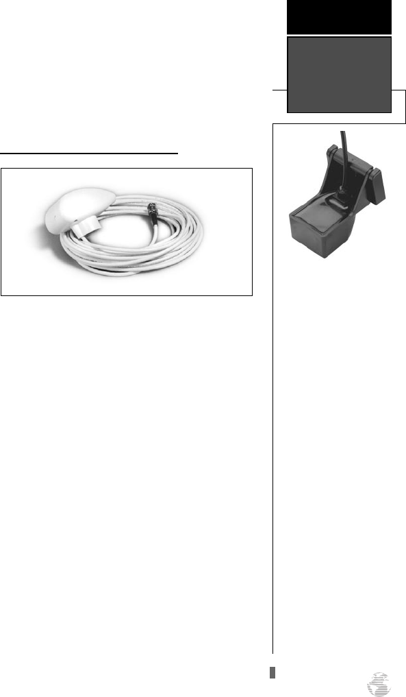
Two types of antenna assemblies are used with the
GPS 125 Sounder:
• White, GA28 Marine Antenna with 30 ft. cable
and BNC connector
• Black, GA26 Low-Profile Antenna with 8 ft.
cable, BNC connector, flange, and Velcro™
mounting hardware.
Mounting the White, GA28 Antenna
To install the GA28 antenna:
1. Attach a 1” X 14 mount (not included) to the desired
antenna location using the appropriate fasteners.
2. Screw the antenna directly onto the 1” X 14 mount.
3. Route the cable to the location of the GPS 125 Sounder,
using the appropriate tie-wraps,escutcheon plates, and
sealant to secure the cable along the route and through
any bulkhead or deck.
4. Once the GPS 125 Sounder unit has been installed, con-
nect the cable to the antenna connector on the back of
the unit. Turn the antenna connector 1/4 turn clockwise
to lock the cable into place.
65
APPENDIX A
Installation
Transducer Installation:
For instructions on transduc-
er installation, see the
booklet included with your
transducer.
125 Man Rev B 7/23/98 11:48 AM Page 65
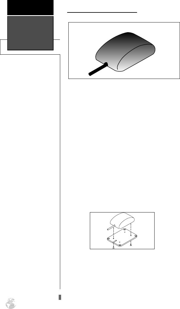
Mounting the GPS 125 Sounder
Two types of mounting options are included with
the GA26:
• Flange Mount Bracket
• Dual-Lock Velcro Strips
The flange mount bracket is useful for permanent
antenna mounting on a flat surface.
The dual-lock Velcro should be considered perma-
nent even though it does not require drilling. The adhe-
sive used to attach the Velcro to the antenna and the
mounting surface is very strong. Removing an item
attached with dual-lock Velcro could result in damage
to the antenna or to the mounting surface.
To flange mount the GA26 antenna:
1. Attach the flange mount bracket to the GA26 using the
two M3 screws included with the antenna.
Installation
APPENDIX A
66
125 Man Rev B 7/23/98 11:48 AM Page 66
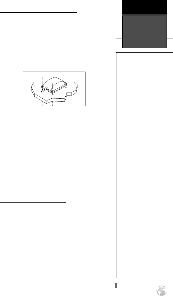
Mounting the GA 26 Antenna (cont.)
2. Using the mounting bracket as a template, mark and then
drill four 0.115-.125” holes.
3. If necessary, apply silicone sealant between the mount-
ing surface and flange mount and then attach the anten-
na to the mounting surface with appropriate screw (not
included).
4. Note: If installation requires that the antenna cable be rout-
ed through the mounting surface, you will need to make a
0.700” cable hole in the mounting surface.
To Velcro mount the GA26 antenna:
1. Ensure the mounting surface and the back of the GA26
antenna are both clean.
2. Remove the backing from each of the Velcro strips,
attach them to the desired locations, and press the
antenna onto the mounting surface.
Mounting the GPS 125 Sounder
The GARMIN GPS 125 Sounder’s compact case is
suitable for mounting in exposed locations or at the
nav station. The unit comes with a gimbal bracket that
can be used for surface, overhead, or flush mounting.
When choosing a location for the display unit, make
sure you consider the following conditions:
67
APPENDIX A
Installation
125 Man Rev B 7/23/98 11:48 AM Page 67
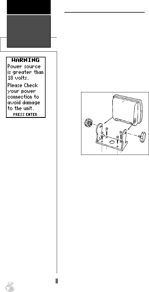
Mounting the GPS 125 Sounder (cont.)
• There should be at least 2.00” (5.0 cm) clearance
behind the case to allow connection of the anten-
na, power/data cable, and transducer cable.
• The mounting surface should be rigid enough to
support the unit and protect it from excessive
vibration and shock.
• The GPS 125 Sounder screen has crisp contrast in
most lighting conditions, even full sunlight.
To surface mount the GPS 125 Sounder:
1. Place the mounting bracket in the desired location.
2. Mark and drill the four mounting holes for the fasten-
ers you are using.
3. Fasten the bracket to the surface using the appropri-
ate fasteners.
4. Insert the GPS 125 Sounder into the mounting bracket.
5. Screw the two mounting knobs through the bracket
and into the GPS 125 Sounder.
6. Connect the power/data, antenna, and transducer
cables to the back of the unit, making sure the locking
rings are fully tightened on both connectors.
Installation
APPENDIX A
68
WARNING
If your power source ever
exceeds 18 volts, the above
warning page will appear.
The GPS 125 Sounder will
automatically discontinue
standard operation to
avoid system overload and
will allow only screen
backlighting operation.
Should this warning
appear, you should check
your power source and
reduce voltage to the unit
to between 12 and 18
volts.
125 Man Rev B 7/23/98 11:48 AM Page 68
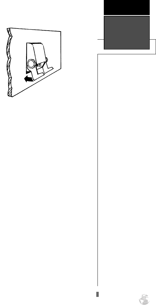
To flush mount the GPS 125 Sounder:
The GPS 125 Sounder can be mounted flush with a
flat panel of .08-.52” thickness using the cam lobe fea-
ture on its mounting bracket.
1. Cut a 4.15” W x 4.67” H hole in panel.
2. Place GPS 125 Sounder into hole from the front until
its flange rests against the mounting surface.
3. From the back side of the panel, loosely attach the
bracket such that the slot in the ratchet area points
away from the mounting panel.
4. Rotate the bracket downward until the panel
is pinched tightly between the units flange
and bracket lobe.
5. Tighten knobs and connect the power/data, antenna,
and transducer cables.
69
APPENDIX A
Installation
125 Man Rev B 7/23/98 11:48 AM Page 69
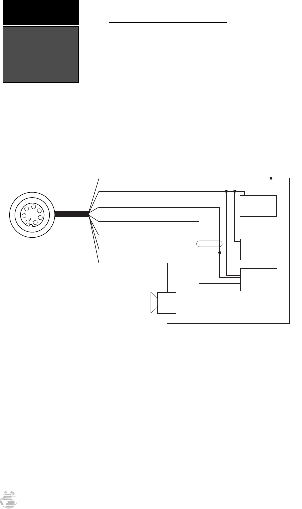
Wiring &
Specifications
APPENDIX B
70
Connecting the power/data cable
The power/data cable connects the GPS 125 Sounder
system to a 12-18 volt DC power source and provides
interface capabilities for connecting NMEA devices and
an external alarm (see below for interface operation
details). The diagram below indicates the appropriate har-
ness connections.
To connect the GPS 125 Sounder to a power source:
1. Connect the RED harness lead to the positive side of a 12-18 volt DC power source. Make sure
the power lead has an in-line 1-amp fuse installed.
2. Connect the BLACK harness lead to a ground strip or the negative side of a
12-18 volt DC power source.
To connect an external alarm, connect the ground side of the alarm device to the
YELLOW harness lead. (100 mA DC load max.) The following interface formats are sup-
ported by the GPS 125 Sounder for driving three NMEA devices:
NMEA 0180, NMEA 0182,
NMEA 0183 version 1.5:
Approved sentences:
GPBWC, GPGLL, GPRMB, GPRMC,
GPXTE, GPVTG, GPWPL
Proprietary sentences:
PGRMM (map datum), PGRMZ
(altitude), PSLIB (beacon rec. control)
NMEA 0183 version 2.0:
Approved sentences:
GPGGA, GPGLL, GPGSA, GPGSV,
GPRMB, GPRMC, GPRTE, GPWPL
Proprietary sentences:
PGRME (estimated error), PGRMM
(map datum), PGRMZ (altitude), PSLIB
(beacon receiver control)
PIN 1 (red): 12-18 volts DC
PIN 2 (black): Ground
PIN 3 (blue): NMEA out
PIN 4 (brown): NMEA in
PIN 5 (white): No connection
PIN 6 (green): No connection
PIN 7 (yellow): alarm low
1
2
345
6
7
Pin assignment
(-) (+)
12-18 volts DC
Autopilot/
NMEA Device
GBR 21
Beacon
Receiver
Alarm/
Relay
(-)
Shield Grounded
Through GPS
(+)
125 Man Rev B 7/23/98 11:48 AM Page 70

71
APPENDIX B
Wiring &
Specifications
PHYSICAL
Case: gasketed-construction
Size: 4.9”H x 5.3”W x 2.4”D
(15.6 x 5.1 x 1.23 cm)
Weight: Less than 1 lb. (454g)
Temperature Range: 5º to 158ºF (-15º to 70ºC)
PERFORMANCE
Receiver: Differential-ready MultiTrac8
TM
Acquisition Time: Approx. 20 seconds (warm)
Approx. 2 minutes (cold)
Approx. 7.5 minutes (AutoLocate
TM
)
Update Rate: 1/second, continuous
Position Accuracy: 5-10 meters (16-33 ft.) with DGPS corrections*
15 meters (49 ft.) RMS**
Velocity Accuracy: 0.1 knot RMS steady state, 99 knots max.
Dynamics: Performs specification to 3g’s
POWER
Input: 12-18v DC
Usage: 5 watts
Specifications subject to change without notice
* With optional GARMIN GBR 21 Beacon Receiver Input.
** Subject to accuracy degradation to 100m 2DRMS under the US DOD-imposed elective
Availability Program.
The GPS 125 Sounder is constructed of high-quality
materials and should not require user maintenance. Should
your unit ever need repair, please take it to an authorized
GARMIN service center. The GPS 125 Sounder has no
user-serviceable parts. Never attempt any repairs yourself.
To protect your GPS, never allow gasoline or other sol-
vents to come in contact with the case or screen. Clean the
case and screen with a soft cloth and a household window
cleaner.
125 Man Rev B 7/23/98 11:48 AM Page 71

Messages &
Time Offsets
APPENDIX C
72
Active WPT Can’t be Deleted—You have attempted to change the “active to”’ or “active from”
waypoint. Clear the active route or GOTO before making your changes.
Accuracy has been Degraded—The accuracy of the GPS 125 Sounder has been degraded
beyond 500 meters due to poor satellite geometry or data quality. You should check other navi-
gational sources to verify the position indicated.
Already Exists—The name you are entering already exists in the GPS 125 Sounder’s memory.
Approaching—You are one minute away from reaching a destination waypoint.
Deep Water Alarm—The current depth is equal to or more than the set alarm depth.
No DGPS Position—Not enough data is available to compute a DGPS position.
No RTCM Input—
Beacon receiver is improperly connected or baud rates do not match.
Poor GPS Coverage—The GPS 125 Sounder cannot acquire the necessary number of satellites
to compute a position. Try another location with a clearer view of the sky.
Power Down and Re-init—The GPS 125 Sounder is not able to calculate a position due to
abnormal satellite conditions. Turn the unit off and verify the last position shown by other
means. Try the unit again later, possibly in a different location.
Read Only Mem has Failed—The permanent memory has failed and the unit is not operable.
Take your unit to an authorized GARMIN dealer for repairs.
Received an Invalid WPT—A waypoint was received during upload transfer that has an invalid
identifier.
Receiver has Failed—A failure in receiver hardware has been detected. If this message persists,
do not use the unit and take it to an authorized dealer for repair.
Route is Full—You have attempted to add more than 30 waypoints to a route.
Route is not Empty—You have attempted to copy into a route already in use.
Route Waypoint Can’t be Deleted—The waypoint you are trying to delete is part of a route.
Delete the waypoint from the route before removing it from memory.
Route Waypoint was Deleted—A route waypoint entered does not exist in the database and
has been deleted from the route.
RTCM Input has Failed—DGPS data being received has been lost. You are no longer receiving
the beacon signal.
Route Waypoint was Deleted—A route waypoint entered does not exist in the database and
has been deleted from the route.
The GPS 125 Sounder uses a flashing on-screen mes-
sage to alert you to important information. Whenever the
message indicator appears, press the PAGE key to view the
message page. There are two types of messages: temporary
alerts and condition alerts. Temporary alerts are cleared
from the message page after viewing, while condition alerts
remain on the message page until the condition has been
resolved. Pay careful attention to all messages for your
own safety.
125 Man Rev B 7/23/98 11:48 AM Page 72

Longitudinal Zone Offset Longitudinal Zone Offset
W180.0º to W172.5º -12 E007.5º to E022.5º 1
W172.5º to W157.5º -11 E022.5º to E037.5º 2
W157.5º to W142.5º -10 E037.5º to E052.5º 3
W142.5º to W127.5º -9 E052.5º to E067.5º 4
W127.5º to W112.5º -8 E067.5º to E082.5º 5
W112.5º to W097.5º -7 E082.5º to E097.5º 6
W097.5º to W082.5º -6 E097.5º to E112.5º 7
W082.5º to W067.5º -5 E112.5º to E127.5º 8
W067.5º to W052.5º -4 E127.5º to E142.5º 9
W052.5º to W037.5º -3 E142.5º to E157.5º 10
W037.5º to W022.5º -2 E157.5º to E172.5º 11
W022.5º to W007.5º -1 E172.5º to E180.0º 12
W007.5º to E007.5º 0
RTCM Input has Failed—DGPS data being received has been lost. You are no longer receiving
the beacon signal.
Searching the Sky—The GPS 125 Sounder is in searching the sky for almanac data or the unit
is in AutoLocate
TM
mode.
Shallow Water Alarm—The depth is equal to or less than the set alarm depth
Sonar ASIC has Failed—The unit’s internal monitoring system indicates a malfunction. Send in
for service as soon as possible.
Stored Data was Lost—All waypoints, routes, time and almanac data has been lost due to bat-
tery failure or clearing the receiver’s memory.
Transfer has been Completed—The receiver is finished uploading or downloading information
to the connected device.
No Transducer-Sounder Off—The transducer signal is not reaching the unit because of a loose
connector, bad wiring, or transducer malfunction.
WPT Memory is Full—You have used all 250 waypoints in the GPS 125 Sounder. Delete
unwanted waypoints to make room for new entries.
The chart below gives the UTC time offset for the various longitudinal zones. If
you are in daylight savings time, add one hour to the offset.
73
APPENDIX C
Messages &
Time Offsets
125 Man Rev B 7/23/98 11:48 AM Page 73
Map Datums
APPENDIX D
74
The following list shows the 104 map datums
available for the GPS 125 Sounder. Abbreviations
are listed first, followed by the corresponding
map datum name and area.
Adindan Adindan- Ethiopia, Mali,
Senegal, Sudan
Afgooye Afgooye- Somalia
AIN EL ABD ‘70 AIN EL ANBD 1970-
Bahrain Island, Saudi Arabia
Anna 1 Ast ‘65 Anna 1 Astro ‘65- Cocos Isl.
ARC 1950 ARC 1950- Botswana,
Lesotho, Malawi, Swaziland,
Zaire, Zambia, Zimbabwe
ARC 1960 ARC 1960- Kenya, Tanzania
Ascnsn Isld ‘58 Ascension Island ‘58-
Ascension Island
Astro B4 Sorol Astro B4 Sorol Atoll- Tern
Island
Astro Bcn “E” Astro Beacon “E”- Iwo Jima
Astro Dos 71/4 Astro Dos 71/4- St. Helena
Astr Stn ‘52 Astronomic Stn ‘52- Marcus
Island
Astrln Geod ‘66 Australian Geod ‘66-
Australia, Tasmania Island
Astrln Geod ‘84 Australian Geod ‘84-
Australia, Tasmania Island
Bellevue (IGN) Efate and Erromango Islands
Bermuda 1957 Bermuda 1957- Bermuda
Islands
Bogata Observ Bogata Obsrvatry- Colombia
Campo Inchspe Campo Inchauspe- Argentina
Canton Ast ‘66 Canton Astro 1966- Phoenix
Islands
Cape Cape- South Africa
Cape Canavrl Cape Canaveral- Florida,
Bahama Islands
Carthage Carthage- Tunisia
CH-1903 CH 1903- Switzerland
Chatham 1971 Chatham 1971- Chatham
Island (New Zealand)
Chua Astro Chua Astro- Paraguay
Corrego Alegr Corrego Alegre- Brazil
Djakarta Djakarta (Batavia)- Sumatra
Island (Indonesia)
Dos 1968 Dos 1968- Gizo Island
(New Georgia Islands)
Easter Isld 67 Easter Island 1967
European 1950 European 1950- Austria,
Belgium, Denmark, Finland,
France, Germany, Gibraltar,
Greece, Italy, Luxembourg,
Netherlands, Norway,
Portugal, Spain, Sweden,
Switzerland
125 Man Rev B 7/23/98 11:49 AM Page 74

75
APPENDIX D
Map Datums
European 1979 European 1979- Austria,
Finland, Netherlands,
Norway, Spain, Sweden,
Switzerland
Finland Hayfrd Finland Hayford-
Finland
Gandajika Base Gandajika Base- Republic
of Maldives
Geod Datm ‘49 Geodetic Datum ‘49-
New Zealand
Guam 1963 Guam 1963-
Guam Island
Gux 1 Astro Gux 1 Astro-
Guadalcanal Island
Hjorsey 1955 Hjorsey 1955- Iceland
Hong Kong ‘63 Hong Kong ‘63-
Hong Kong
Hu-Tzu-Shan Hu-Tzu-Shan- Taiwan
Indian Bngldsh Indian- Bangladesh,
India, Nepal
Indian Thailand Indian- Thailand,
Vietnam
Indonesia ‘74 Indonesia 1974-
Indonesia
Ireland 1965 Ireland 1965- Ireland
ISTS 073 Astro ISTS 073 ASTRO ‘69-
Diego Garcia
Johnston Island Johnston Island
Kandawala Kandawala-
Sri Lanka
Kerguelen Islnd Kerguelen Island
Kertau 1948 Kertau 1948- West
Malaysia, Singapore
L. C. 5 Astro Cayman Brac Island
Liberia 1964 Liberia 1964- Liberia
Luzon Mindanao Luzon- Mindanao Island
Luzon Philippine Luzon- Philippines
(excluding Mindanao
Island)
Mahe 1971 Mahe 1971- Mahe Island
Marco Astro Marco Astro- Salvage
Island
Massawa Massawa- Eritrea
(Ethiopia)
Merchich Merchich- Morocco
Midway Ast ‘61 Midway Astro ‘61-
Midway
Minna Minna- Nigeria
NAD27 Alaska North American 1927-
Alaska
NAD27 Bahamas North American 1927-
Bahamas (excluding San
Salvador Island)
NAD27 Canada North American 1927-
Canada and
Newfoundland
NAD27 Canal Zone North Am. 1927- Canal
Zone
NAD27 Caribbn North American 1927-
Caribbean (Barbados,
Caicos Islands, Cuba,
Dom. Rep., Grand
Cayman, Jamaica,
Leeward and Turks
Islands)
NAD27 Central North American 1927-
Central America (Belize,
Costa Rica,
El Salvador, Guatemala,
Honduras, Nicaragua)
NAD27 CONUS North Am. 1927- Mean
Value (CONUS)
NAD27 Cuba North American 1927-
Cuba
NAD27 Grnland North American 1927-
Greenland
(HayesPeninsula)
NAD27 Mexico N. American 1927-
Mexico
NAD27 San Sal North American 1927-
San Salvador Island
NAD83 North American 1983-
Alaska, Canada, Central
America, CONUS,
Mexico
125 Man Rev B 7/23/98 11:49 AM Page 75

Map Datums
APPENDIX D
76
Nhrwn Masirah Nahrwn- Masirah Island
(Oman)
Nhrwn Saudi A Nahrwn- Saudi Arabia
Nhrwn United A Nahrwn- United Arab
Emirates
Naparima BWI Naparima BWI- Trinidad
and Tobago
Obsrvtorio ‘66 Observatorio 1966-
Corvo and Flores Islands
(Azores)
Old Egyptian Old Egyptian- Egypt
Old Hawaiian Old Hawaiian- Mean
Value
Oman Oman- Oman
Ord Srvy GB Old Survey Grt Britn-
England, Isle of Man,
Scotland, Shetland Isl.,
Wales
Pico De Las Nv Canary Islands
Ptcairn Ast ‘67 Pitcairn Astro ‘67-
Pitcairn Isl.
Prov S Am ‘56 Prov So Amricn ‘56-
Bolivia, Chile,Colombia,
Ecuador, Guyana, Peru,
Venezuela
Prov S Chln ‘63 Prov So Chilean ‘63- S.
Chile
Puerto Rico Puerto Rico & Virgin
Islands
Qatar National Qatar National- Qatar
Qornoq Qornoq- South
Greenland
Reunion Reunion- Mascarene
Island
Rome 1940 Rome 1940- Sardinia
Island
RT 90 Sweden
Santo (Dos) Santo (Dos)- Espirito
Santo Island
Sao Braz Sao Braz- Sao Miguel,
Santa Maria Islands
(Azores)
Sapper Hill ‘43 Sapper Hill 1943- East
Falkland Island
Schwarzeck Schwarzeck- Namibia
Sth Amrcn ‘69 South American ‘69-
Argentina, Bolivia, Brazil,
Chile, Colombia,
Ecuador, Guyana,
Paraguay, Peru,
Venezuela, Trinidad and
Tobago
South Asia South Asia- Singapore
SE Base Southeast Base- Porto
Santo and Madiera
Islands
SW Base Southwest Base- Faial,
Graciosa, Pico, Sao Jorge
and Terceira Islands
(Azores)
Timbalai 1948 Timbalai 1948- Brunei
and E. Malaysia (Sarawak
and Sabah)
Tokyo Tokyo- Japan, Korea,
Okinawa
Tristan Ast ‘68 Tristan Astro 1968-
Tristan da Cunha
Viti Levu 1916 Viti Levu 1916- Viti
Levu/ Fiji Islands
Wake-Eniwetok Wake-Eniwetok-
Marshall Isl.
WGS 72 World Geodetic System
1972
WGS 84 World Geodetic System
1984
Zanderij Zanderij- Surinam
125 Man Rev B 7/23/98 11:49 AM Page 76

APPENDIX E
77
Index
A
Almanac Data . . . . . . . . . . . . . . . . . . . . . .2
Alarms Setup . . . . . . . . . . . . . . . . . . . . .57
B
Backlighting . . . . . . . . . . . . . . . . . . . . . . .9
Bearing (BRG) . . . . . . . . . . . . . . . . . . . . .2
C
Cancelling a GOTO . . . . . . . . . . . . .14, 28
CDI Scale Settings . . . . . . . . . . . . . . . . .53
Compass Page . . . . . . . . . . . . . . . . . . . . .9
Connecting the Power/Data Cable . . . . . .70
Course Made Good (CMG) . . . . . . . . . . . .2
Crosstrack Error (XTE) . . . . . . . . . . . . . . .2
D
Date and Time Setup . . . . . . . . . . . . . . .52
Desired Track (DTK) . . . . . . . . . . . . . . . .2
DGPS Interface . . . . . . . . . . . . . . . . . . . .50
Differential GPS (DGPS) . . . . . . . . . . . . . .2
Distance and Sun Calculation . . . . . . . . .47
E
Estimated Time Enroute (ETE) . . . . . . . . .2
Estimated Time of Arrival (ETA) . . . . . . . .2
EZinit . . . . . . . . . . . . . . . . . . . . . . . . . . .6
G
Getting Started Tour . . . . . . . . . . . . . . . . .7
Glossary . . . . . . . . . . . . . . . . . . . . . . . . . .2
Ground Speed (SOG) . . . . . . . . . . . . . . . .2
H
Highway Page . . . . . . . . . . . . . . . . . . . . .9
I
Initialization Troubleshooting . . . . . . . . . .7
Initializing the Receiver . . . . . . . . . . . . .5-6
Installation . . . . . . . . . . . . . . . . . . . . . . .64
Interface Options . . . . . . . . . . . . . . . . . .49
Interface Setup . . . . . . . . . . . . . . . . . . . .49
Introduction . . . . . . . . . . . . . . . . . . . . . .iii
L
Latitude . . . . . . . . . . . . . . . . . . . . . . . . . .3
Longitude . . . . . . . . . . . . . . . . . . . . . . . .3
M
Magnetic Heading Reference . . . . . . . . . .54
Man Overboard Function . . . . . . . . . . . .28
Map Datums . . . . . . . . . . . . . . . . . .53, 74
Map Page . . . . . . . . . . . . . . . . . . . . . . . . .9
Clearing a Cluttered Map Display . . .17
Map Setup and Orientation . . . . . . . .55
Selecting Items on the Map Page . . . .56
Track Log Display . . . . . . . . . . . . . . .56
Track Log Setup . . . . . . . . . . . . . . . .47
Using the Cursor on the Map . . . . . .43
Using the Position and Map Pages . . .11
Zooming, Panning, and Pointing . . . .42
Zoom Scale . . . . . . . . . . . . . . . . . . . .42
Menu Page . . . . . . . . . . . . . . . . . . . . . . . .9
Messages . . . . . . . . . . . . . . . . . . . . . . . .72
Mounting the Antenna . . . . . . . . . . . . . .65
Mounting the GPS 125 Sounder . . . . . . .67
N
Navigation Basics . . . . . . . . . . . . . . . . . . .4
Navigation Page . . . . . . . . . . . . . . . . . . . .9
Navigation Setup . . . . . . . . . . . . . . . . . .53
Navigation Simulator . . . . . . . . . . . .10, 62
O
Operating Modes . . . . . . . . . . . . . . . . . .51
P
Position . . . . . . . . . . . . . . . . . . . . . . . . . .3
Position Formats . . . . . . . . . . . . . . . . . .53
Position Page . . . . . . . . . . . . . . . . . . . . . .8
Power Input . . . . . . . . . . . . . . . . . . . . . .70
Power Overload Message . . . . . . . . . . . .68
Power Usage . . . . . . . . . . . . . . . . . . . . .70
Primary Pages . . . . . . . . . . . . . . . . . . . . .8
125 Man Rev B 7/23/98 11:49 AM Page 77

Index
APPENDIX E
78
R
Receiver Status . . . . . . . . . . . . . . . . . . . .19
Routes . . . . . . . . . . . . . . . . . . . . . . .31-36
Active From Waypoint . . . . . . . . . . .31
Active Leg . . . . . . . . . . . . . . . . . . . . .31
Active Route Page . . . . . . . . . . . . . . .35
Active To Waypoint . . . . . . . . . . . . . .31
Activating and Inverting . . . . . . . . . .34
Copying . . . . . . . . . . . . . . . . . . . . . .33
Clearing . . . . . . . . . . . . . . . . . . . . . .33
Creating and Navigating . . . . . . . . . .31
Editing . . . . . . . . . . . . . . . . . . . . . . .35
On-Route GOTOs . . . . . . . . . . . . . . .36
Route Definition Page . . . . . . . . . . . .32
S
Satellite Page . . . . . . . . . . . . . . . . . . . . . .8
Screen Contrast . . . . . . . . . . . . . . . . . . .52
Selecting a GOTO Destination . . . . . . . .12
Sounder Page . . . . . . . . . . . . . . . . . . . . . .8
Auto Range Mode . . . . . . . . . . . . . . .15
Chart Speed . . . . . . . . . . . . . . . . . . .58
Depth Controlled Gain (DCG) . . . . . .37
Depth Units . . . . . . . . . . . . . . . . . . .60
Fish Icon . . . . . . . . . . . . . . . . . . . . .37
Fish ID . . . . . . . . . . . . . . . . . . . . . . .59
Keel Offset . . . . . . . . . . . . . . . . . . . .61
Manual Range Mode . . . . . . . . . . . . .15
Moving the Zoom Window . . . . . . . .16
Noise Rejection . . . . . . . . . . . . . . . . .60
Range Modes . . . . . . . . . . . . . . .15, 59
See-Thru Technology . . . . . . . . . . . . .37
Sensitivity . . . . . . . . . . . . . . . . . . .3, 58
Sounder Alarms . . . . . . . . . . . . . . . .61
Sounder Setup . . . . . . . . . . . . . .40, 58
Sounder Zoom . . . . . . . . . . . . . . . . .15
Thermocline . . . . . . . . . . . . . . . . .3, 14
Underwater Waypoint Feature . . .15, 38
Using the Sounder Page . . . . . . . . . . .14
Whiteline . . . . . . . . . . . . . . . . . . .3, 59
Zoom Function . . . . . . . . . . . . . . . . .39
Specifications . . . . . . . . . . . . . . . . . . . . .71
Speed Filter . . . . . . . . . . . . . . . . . . . . . .54
Speed Over Water (SOW) . . . . . . . . . . . . .3
Starting/Stopping a GOTO . . . . . . . . . . .28
System Setup . . . . . . . . . . . . . . . . . . . . .51
T
Table of Contents . . . . . . . . . . . . . . . . . . .1
Temperature Range . . . . . . . . . . . . . . . . .71
Time Format . . . . . . . . . . . . . . . . . . . . .52
Time Offsets . . . . . . . . . . . . . . . . . . . . . .73
Tips On Using the TracBack Feature . . . .30
Tone Setting . . . . . . . . . . . . . . . . . . . . . .52
TracBack Navigation . . . . . . . . . . . . . . . .29
Track (TRK) . . . . . . . . . . . . . . . . . . . . . . .3
Track Criteria . . . . . . . . . . . . . . . . . . . . .48
Transducer Installation . . . . . . . . . . . . . .65
Trip Odometer . . . . . . . . . . . . . . . . . . . .20
Turning the GPS 125 Sounder Off . . . . . . .7
Turning the GPS 125 Sounder On . . . . . . .6
U
Units of Measure . . . . . . . . . . . . . . . . . .54
Universal Transverse Mercator (UTM) . . . .3
Using the Compass Page . . . . . . . . . . . . .46
Using the Highway Page . . . . . . . . . .13, 45
V
Velocity Made Good (VMG) . . . . . . . . . . .3
W
Waypoint . . . . . . . . . . . . . . . . . . . . . . . . .3
Editing . . . . . . . . . . . . . . . . . . . . . . .26
Going To a Waypoint . . . . . . . . . . . .12
Marking a Waypoint . . . . . . . . . .10, 21
Nearest Waypoints Page . . . . . . . . . .22
Reference Waypoints . . . . . . . . . . . . .25
Deleting . . . . . . . . . . . . . . . . . . . . . .26
Renaming . . . . . . . . . . . . . . . . . . . . .26
Scanning Waypoints . . . . . . . . . . . . .27
Waypoint Comments . . . . . . . . . . . . .26
Waypoint Definition Page . . . . . . . . .24
Waypoint List Page . . . . . . . . . . . . . .23
125 Man Rev B 7/23/98 11:49 AM Page 78

LIMITED WARRANTY
GARMIN Corporation warrants this product to be free from
defects in materials and workmanship for one year from the date of
purchase. GARMIN will at its sole option, repair or replace any com-
ponents which fail in normal use. Such repairs or replacement will be
made at no charge to the customer for parts or labor. The customer is,
however, responsible for any transportation costs. This warranty does
not cover failures due to abuse, misuse, accident or unauthorized
alteration or repairs. GARMIN assumes no responsibility for special,
incidental, punitive or consequential damages, or loss of use.
The warranties and remedies contained herein are exclusive and
in lieu of all other warranties expressed or implied, including any lia-
bility arising under warranty of merchantability or fitness for a partic-
ular purpose, statutory or otherwise. This warranty gives you specific
legal rights, which may vary from state to state.
To obtain warranty service, call the GARMIN Customer Service
department (913-397-8200) for a returned merchandise tracking
number. The unit should be securely packaged with the tracking
number clearly marked on the outside of the package, and sent freight
prepaid and insured to a GARMIN warranty service station. A copy of
the original sales receipt is required as the proof of purchase for war-
ranty repairs. GARMIN retains the exclusive right to repair or replace
the unit or software at its sole discretion.
125 Man Rev B 7/23/98 11:49 AM Page 79

© 1997 GARMIN Corporation
1200 E. 151st Street, Olathe, KS USA 66062
GARMIN (Europe) LTD - Unit 5, The Quadrangle,
Abbey Park Industrial Estate, Romsey, UK SO51 9AQ
Part Number 190-00111-00 Rev. B Printed in Taiwan
125 Man Rev B 7/23/98 11:49 AM Page 80
