Garmin M2AINX01 LOW POWER TRANSMITTER (2400-2483.5 MHz) User Manual 1
Garmin International Inc LOW POWER TRANSMITTER (2400-2483.5 MHz) 1
UserManual.wiki
>
Garmin
>
M2AINX01 User Manual
>
User Manual 1
Contents
1.
User Manual 1
2.
User Manual 2
User Manual 1
Navigation menu
Upload a User Manual
Namespaces
Wiki Guide
HTML
PDF
Info
Views
User Manual
Discussion / Help
Navigation
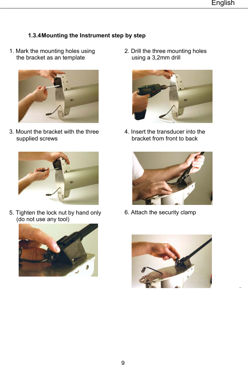
![English 13 7 First start (only in a Network) 7.1 Initialising the instrument At power on, the inst rument will perform a self test. T he display will first show all segments, then the softw are version number and the Network ID number. At first power on after installation, you will be asked to press the SET button key [PrS KEY]. This will give the instrument a logical ID number on the Network. To initialise the instrument, press SET on all installed digital instrument, one at the time but only after the instrument show OK. Note: Always wait for the text ”Init OK” to be displayed, before you press SET on the next instrument! The Server automatically gives the first unit ID number 16, then 17 and so on. T he order in w hich y ou press SET is the same order as the instruments w ill be given a logical ID number on the Nexus Network. The example shows that the inst rument version number is 1.00 and the given logical ID number is 16. 7.2 Re-initialising the instrument If two instruments by mistake have the same ID number, this can cause disturbance and block the information on the Nexus Network. To re-initialise the instrument, press MINUS and PLUS together during the pow er up sequence w hen version and ID numbers are displayed.](https://usermanual.wiki/Garmin/M2AINX01.User-Manual-1/User-Guide-1880115-Page-11.png)
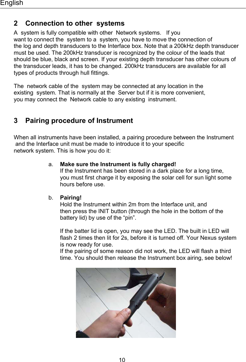
![22 10 Maintenance and fault finding 10.1 Maintenance • To clean the instrument, use only mild soap solution and rinse with water. • Do not use detergents or high pressure washing equipment. • At least once a y ear, check all y our connections and apply additional silicon paste at each connection point. • Always use the instrument cover for protection, when not in use. • Storing transducers and instruments w hen not in use for longer periods: It is advisable to remove the instruments and transducers, and stor e them inside the boat or at home in room temperature, if possible. 10.2 Fault finding Before you contact y our dealer, and to assist y our dealer to give y ou a better service, please check the following points and make a list of: • All connected instrument and transducers, including their software version numbers. • Instrument software version number. • Network data bus ID numbers for each instrument (displayed at power up). 10.2.1 General In most cases, the reason for faults in el ectronic equipment is t he installation or poor connections. Therefore, always first check that: • Installation and connection is made per inst ructions for instrument and transducers, (see chapter 1). • Screw terminals are carefully tightened. • No corrosion on any connection points. • No loose ends in the wires causing short cuts to adjacent wires. • Cables for damage, that no cables are squeezed or worn. • Battery voltage is sufficient, should be at least 10 V DC. • The fuse is not blown and the circuit-breaker has not opened. • The fuse is of the right type. • Two instruments do not have the same ID number, (see chapter 7.2). • Check the following important setting: C18 10.2.2 Fault - action 1. : No reading [ --- ] • If inaccurate data is received, check the connections (separate through deck connection or below decks connection), are properly made. • Make sure the Instrument is aligned correctly, (see C54, 9.2.3). • Check the setting of C18. 2. functions: No reading [ --- ] • C16 should be BSP. See 9.1.6.](https://usermanual.wiki/Garmin/M2AINX01.User-Manual-1/User-Guide-1880115-Page-12.png)