Garnet Systems Co GAE3030 ADSL Modem User Manual USER GUIDE GAE 3020 ver2 1
Garnet Systems Co Ltd ADSL Modem USER GUIDE GAE 3020 ver2 1
users manual
Garnet ADSL Ethernet Modem
GAE-3030
User’s Guide
Ver. 2.1
Garnet Systems Co., Ltd.
All rights reserved. Passing on and copying of this document, use and communication of
its contents not permitted without written authorization from Garnet Systems Co., Ltd.
Contents
Chapter 1. Overview ------------------------------------------ 3
1.1 Introduction ------------------------------------------------------ 3
1.2 Features ----------------------------------------------------------- 3
1.3 Specifications --------------------------------------------------- 4
Chapter 2. Installation ---------------------------------------- 5
2.1 Before Installation -------------------------------------------- 5
2.2 Delivery Check --------------------------------------------------- 5
2.3 Hard Ware Installation ----------------------------------------- 7
2.4 Soft Ware Installation ------------------------------------------ 7
2.5 Ethernet Bridge Configuration ----------------------------- 8
2.6 Ethernet Router Configuration ----------------------------- 8
2.7 IPoA Routing ----------------------------------------------------- 9
2.8 PPP Routing ------------------------------------------------------ 10
2.9 NAT ------------------------------------------------------------------ 11
2.10 DHCP Server ---------------------------------------------------- 11
2.11 Updating Npimage -------------------------------------------- 12
2.12 PHY Flash Update ------------------------------------------- 13
2.13 VCI/VPI Value Configuration ------------------------------- 14
2.14 RFC 1483 (PPP over Ethernet) S/W Installation ----- 16
Chapter 3. Appendix ----------------------------------------- 17
3.1 Connector Specification --------------------------------------------- 17
3.2 Warranty ------------------------------------------------------------ 18
3.2 Regulatory information ----------------------------------------- 19

GARNET GAE-3030
3
Chapter 1. Overview
1.1 Introduction
Garnet ADSL(Asymmetric Digital Subscriber Line) Modem GAE-3030 is an
External stand-alone modem that provides users faster connectivity than
conventional access technologies by offering up to 8 Mbps of
downstream line rate and up to 640 Kbps of upstream over existing phone
lines, which is asymmetric.
It also provides interoperability and industry standards and protocols.
Garnet ADSL Modem supports either G.992.1(G.dmt) or Splitterless
G.992.2(G.lite) standards via software upgrades.
Garnet ADSL Modem is suitable to be installed into PC, with Plug and Play
function in Windows95/98. Garnet ADSL Modem supports Windows NT,
2000 as well as Rinux and Macintosh.
1.2 Features
??Using Garnet ADSL Modem, you will experience stable, high speed
Internet access and can connect to other multimedia service networks
that ADSL delivers over existing PSTN copper wires.
??Garnet ADSL Modem, using existing phone lines, can help greatly
reduce cost for installing new lines, i.e. optical cables, for high speed
network transmission.
??Compared with conventional dial-up modems, Garnet ADSL Modem
provides high speed network access always on, irrespective of
subscriber numbers. You can simultaneously have phone
conversation.
??Garnet ADSL Modem offers multiple applications such as Internet
access, messenger service, E-mail, file transfer, data download and
upload and etc.
??Garnet ADSL Modem is a customer premise terminal, co-operating
with Central Office equipments. So, the Central Office can effectively
manage subscriber network.

GARNET GAE-3030
4
??Garnet ADSL Modem users can easily monitor with network
monitoring program, which enables users to see speed of data
streams, supports physical connect and disconnect and diagnose
hardware malfunctioning.
1.3 Specifications
??Dimension : 135(L) x 188(W) x 35.5(H)
??Operating Temperature : 0~45 oC
??Operating Humidity : 10% to 90%, non-condensing
??Power Consumption: 5W
??Standards : ANSI T1.413 Issue 2 / ITU-T G.992.1, G.992.2
??Frequency Range : 0.11~1.1MHz(Down) / 30KHz~110KHz(Up)
??Modulation : DMT (Discrete Multi Tone)
??Data Rates : Downstream : Max. 8Mbps, Upstream : Max. 960Kbps
??Interface : 10Base-T Ethernet
??O/S : Win95, Win98, Win NT4.0(Service Pack 3 or higher), Win2000
Rinux, Macintosh
??Minimum System Requirements : Pentium 300MHz CPU, 64MB RAM,
20MB HDD
??Virtual Path & Channel : 8bits VPI, 16bits VCI Address
??WAN Protocol : RFC1483, RFC2364
☞ Note : Data Rates can differ according to distance between DSLAM
and modem, wire gauge, PC specification and other network
environments.
☞ Trademark Notification
▶ Garnet™ is a registered trademark of Garnet Systems Co., Ltd.
▶ Windows™ and Internet Explorer™ is a registered trademark of
Microsoft Corporation.
▶ Ethernet™ is a trademark of Xerox Corporation.

GARNET GAE-3030
5
Chapter 2. Installation
2.1 Before Installation
Please be advised that if you do not yet subscribe phone service, it is
impossible to get ADSL service. In this case, please contact your local
service provider to have new telephone service.
And please be informed that telephone service providers do not service
all ADSL applications. Please contact your local Central Office on the
applications and ADSL service providers may support different service
protocols. Prior to installation, please contact your service providers for
Service Protocols.
2.2.Delivery Check
☞ following materials are provided in the package
A. ADSL Ethernet Modem – GAE-3030
B. Power Adapter – 110/240V, 50/60Hz
C. Console Cable – DB-9 RS-232 port cable
D. RJ45 10base-T Ethernet Cable
E. RJ-11 telephone line
F. User Guide
☞ If you have two or more phones in one phone line, one or more Micro
filters are needed to prevent signal disturbance. To purchase micro filters,
please contact your service provider.
GARNET GAE-3030
6
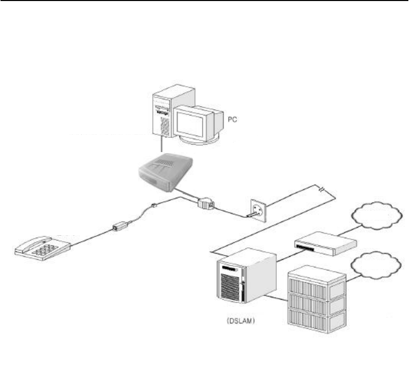
☞ <Figure 1. One example for ADSL Network Configuration>
POTS Micro
Telephone
Ro
Telephone
EXchange
Internet
PSTN
Micro filter
arne
Garnet ADSL Modem Ethernet

GARNET GAE-3030
7
2.3 HardWare Installation
☞ To install modem into PC, follow below steps.
1. Turn off your computer and all attached peripheral devices (printer, monitor,
etc.) and unplug them from the electrical outlet.
? CAUTION : To avoid risk of electric shock, make sure your computer and all
peripheral devices are turned off and unplugged.
2. Attach power supply to power inlet connector
3. Plug power supply cable into standard electrical socket.
4. Connect the RJ11 port to the modem( ) using the phone line
5. For Ethernet Modem installation, connect one end of the Ethernet cross-over
cable to the modem and the other end to the PC. If an Ethernet hub is being used,
a straight–through cable will be needed to attach the modem to the hub.
2.4 SoftWare Installation
☞ The modem has its software image stored in flash. The Ethernet bridge/router
image is stored in flash by default.
In order to use the modem, the modem will need to be configured as a bridge or
router. There is no installation of software on the PC for this, except for the
normal Ethernet LAN adapter installation.
The modem configuration can be viewed and modified through the console
which is accessible through the RS-232 serial connection. To use the serial
interface, a straight-through cable is needed between the modem and a terminal
(could be a PC running a terminal emulation package).
The PHY can be configured to attempt the layer 1 connection in one of the
following modes:
?T1.413

GARNET GAE-3030
8
?G.Lite
?G.dmt
This is configured by setting the BUN attribute AdslMode with the following
console command:
bun set port atm/adslmode=<mode>
Where acceptable value of <mode> are, t1413, glite, gdmt.
Protocol Configuration for configuring the modem for this mode of operation.
2.5 Ethernet Bridge Configuration
In the Ethernet bridge configuration, the modem bridges data between the local
Ethernet LAN and the service provider. The ADSL link must be set up in RFC1483
mode with a PVC to communicate across. The PVC is assigned by the service
provider. The bridge needs to be told about both the Ethernet interface and the
1483 interface. Since the modem is transparent, the PC’s default gateway must
be set to the service provider’s IP address.
The following configuration must be performed to set up the modem for bridge
mode:
? Add the Ethernet device to the bridge:
Bridge device add edd
? Add the ADSL ATM port to the bridge with RFC 1483 enabled:
Bridge device add //bun/port=atm/txvci=32/rxvci=32/rfc1483=true
? Save the configuration and reboot the system:
config save
restart
2.6 Ethernet Router Configuration
There are multiple ways that routing can be set up depending on the
requirements from the service provider.
The following routing methods are described below:
? IPoA Routing

GARNET GAE-3030
9
? PPP Routing
? Routing using NAT (can be used with either IPoA or PPP)
2.7 IPoA Routing
When configured for IPoA, data is routed between Ethernet and Classical IP over
ATM (RFC1577). The IPoA data runs over a PVC between the modem and the
service provider. IP addresses, the PVC and the peak cell rate need to be defined
by the service provider. Since the modem is routing, an IP address needs to be
assigned on both modem’s interfaces. The PC’s default gateway must be set to
the Ethernet IP address of the modem. The following configuration must be
performed to set up the modem for the above example:
? Add the Ethernet device to the router and assign it an IP address. In the
command, “ethernet” is a label used to refer to this device. The arguments
“ether” and “//edd” are required for an Ethernet device.
ip device add ethernet ether //edd 192.168.101.2
? Add the IPoA device to the router and assign it an IP address. In the following
command, “ipoa” is a label used to refer to this device. The arguments “atmpvc”
and “//atm” are required for an IPoA device.
ip device add ipoa atmpvc //atm 192.168.102.2
? Save configuration and reboot system. This is necessary when configuring
the system from the console, because the following commands can only operate
on router interfaces which have already been created.
config save
restart
? Enable forwarding between the router interfaces:
ip relay all
? Add a default route with the service provider as the gateway:
ip route add default 0.0.0.0 192.168.102.3 0:0:0:0
? The next command configures the IPoA protocol to run on PVC 700 with a
peak cell rate of 50000 cells per second, using the port named “atm”:
ip ipatm pvc add ipoa atm 700 pcr 50000
? Save the configuration and reboot the system.
config save

GARNET GAE-3030
10
restart
2.8 PPP Routing
When configured for PPP, data is routed between Ethernet and PPP over ATM.
The PPP data runs over a PVC between the modem and the service provider.
The IP address and PVC need to be defined by the service provider. Since the
modem is routing, an IP address needs to be assigned on both modem’s
interfaces. The PC’s default gateway must be set to the Ethernet IP address of
the modem.
The following configuration must be performed to set up the modem:
? Add the Ethernet device to the router and assign it an IP address. In the
command, “ethernet” is a label used to refer to this device. The arguments
“ether” and “//edd” are required for an Ethernet device.
ip device add ethernet ether //edd 192.168.101.2
? Add the PPP device to the router and assign it an IP address. In the following
command, “ppp_device” is a label for this device. The argument “ether” is
required for a PPP device. The PPP module supports multiple simultaneous
connections, so we explicitly specify Device 1.
ip device add ppp_device ether //ppp/DEVICE=1
We will be using PPP Device 1 and Interface 1, which are able to automatically
configure the IP address of the router interface and add a default route, when the
connection is made. That is why the IP address of the router interface was not
specified in the previous command.
? The following command configures PPP Device 1 for dial-out on PVC 700.
CHAP authentication will be used; PPP will supply a username of “fred” and a
password of “password”.
ppp 1 pvc 700 ip
ppp 1 welogin fred password chap
ppp 1 enable
? Save the configuration and reboot the system. This is necessary when
configuring the system from the console, because the following command can
only operate on router interfaces which have already been created.
config save

GARNET GAE-3030
11
restart
? Enable forwarding between the router interfaces:
ip relay all
? Save the configuration and reboot the system:
config save
restart
2.9 NAT
NAT can be used with IPoA routing or PPP routing. NAT has to be enabled on the
router interface towards the service provider.
The following command enables NAT on a router interface.
ip nat add <interface name>
For the IPoA example previously described the command would be:
ip nat add ipoa
For the PPP example previously described the command would be:
ip nat add ppp_device
2.10 DHCP Server
DHCP can be used to assign IP addresses to PCs connected on the Ethernet
interface of the Client Access Device, as long as the Client Access Device has
been assigned an IP address. In addition to the commands shown in the next
sections, use the following command to get information on all of the DHCP
Server commands:
dhcpserver help
Enabling the DHCP Server
To enable the DHCP server, a range of IP addresses need to be provided that the
server can assign to clients.
The example below shows the commands needed to supply the DHCP server
with 99 IP addresses from 192.168.219.1 to 192.168.219.99 on the subnet
192.168.219.0 with the subnet mask of 255.255.255.0. The maximum lease time
for each client is set to 86400 seconds, or 1 day. BOOTP clients may be

GARNET GAE-3030
12
serviced, and requests from unknown clients are allowed.
The following configuration must be performed for the example:
? Set up the DHCP configuration
dhcpserver
config add allow unknown-clients;
config add allow bootp;
config add subnet 192.168.219.0 netmask 255.255.255.0
config add {
config add range 192.168.219.1 192.168.219.99;
config add max-lease-time 86400;
config add }
config confirm
? Save the configuration and reboot the system:
home
flashfs update
restart
Disabling the DHCP Server
To disable the DHCP server, the configuration information previously supplied
needs to be flushed. To do so, issue the following commands:
? Flush the DHCP configuration
dhcpserver
config flush
config confirm
? Save the configuration and reboot the system:
home
flashfs update
restart
Re-configuring the DHCP Server
To re-configure the DHCP server, issue the disable procedure followed by the
enable procedure.
2.11 Updating the Npimage

GARNET GAE-3030
13
If the ATMOS image(s) have been corrupted and the Client Access Device has
booted in Recovery Mode, it may be necessary to update both the image and
NPimage files. If this is necessary follow the steps in section
2.2.1, copy the NPimage file from the Client Access Device CD to the same
directory as the other TFTP files, and run the following command:
tftp> put NPimage
Either instead of the command:
tftp> put image
or just after it. In other words, it is possible to update the NPimage separately
or during the same update as the image file.
2.12 PHY Flash Update
2.12.1 Updating the PHY flash code
? Power-up the Client Access Device with the Ethernet cable connecting the
board to the house network.
? If the console prompt does not show the board IP address see section 5.1 to
set the IP address.
? On the PC where TFTP is to be run, create a file called tftplock.key which
contains the text “password”.
Also create the files tftpupdt.beg and tftpupdt.end which contain the text “junk”
? Copy the file tftpupdt.nof to the same directory the above files are located in.
? From this directory run TFTP.
? In TFTP, run the following commands:
tftp> connect 172.16.1.239 (substitute the IP address of the test board)
tftp> bin
tftp> put tftplock.key
tftp> put tftpupdt.beg
tftp> put tftpupdt.nof
tftp> put tftpupdt.end
? From the Client Access Device console run the following commands:
172.16.1.239> bun adi super
172.16.1.239> bun adi update

GARNET GAE-3030
14
The driver will display status information during the update procedure. Once
the update is completed turn the board off and then on again for the changes to
take effect. If there is an error in the update procedure, try turning the board off
and then on again and repeating the update process.
2.12.2 PHY Image Conversion Utility
It may be necessary to create the file tftpupdt.nof using the conversion utility
discussed below. When updating the PHY flash image, 3 files are used from the
PHY vendor. These 3 files are converted into 1 file to decrease the number of
files needed and the total file size required during the TFTP process.
If a single converted file is supplied, do not proceed with this step.
2.12.2.1 Files involved
The following files will be supplied by the PHY vendor:
File Default Name Description
Read File readfls.idm This is the executable
code the PHY runs to
read the data from the
flash part.
Program File progfls.idm This is the executable
code the PHY will run to
program data into the
flash part.
PHY Flash Image rt.bnm This is an S-record file
that contains the data to
be programmed into the
PHY flash part.
The default files names shown are what the conversion utility normally expects.
These can be changed using a command line argument.
The output file tftpupdt.nof will be created. This is the file to be used in the TFTP
update process.
2.12.2.2 Command line arguments
The PHY image conversion utility can be run as shown in the following table:
phycon –d Runs the utility with the default file
names to be converted.
phycon –h Displays the help/usage information.
phycon –f <PHY read file> <PHY prog
Causes the utility to use the supplied
file
names instead of the default file

GARNET GAE-3030
15
file> <PHY flash image file> file names instead of the default file
names.
2.12.2.3 Examples
Consider the case where the default file names are used. Run the utility from the
same directory the PHY files are located:
Example : phycon –d Will use the default file names to generate
tftpupdt.nof
Consider the case where the files to use are readfls.idm, progfls23.idm, and
rt930a.bnm:
Example: phycon –f readfls.idm progfls23.idm rt930a.bnm Will use the
given file names to create tftpupdt.nof
2.13 VCI/VPI Value Configuration.
Connect PC to Modem by RJ-45 cable and RS-232 cable, switching power on of
the modem and set up Hyperterminal at Com 1(or Com 2) port for connection
between Modem and PC.
- At the Hyper terminal window, you can see prompt
0:20:2b:8d:40> help <enter>
and you can find existing list of available commands.
- To check existing VCI/VPI value, put in
0:20:2b:8d:40> bridge device
- To delete existing VPI/VCI value, put in
0:20:2b:8d:40> config reset <enter>
0:20:2b:8d:40> config save <enter>
0:20:2b:8d:40> restart <enter>
- To set up new VPI/VCI value, put in
0:20:2b:8d:40> bridge device add edd <enter>
0:20:2b:8d:40> bridge device add //bun/port=atm/txvci=32/txvpi=0/rxvci=32/rxvpi=
0/rfc1483=true <enter>
0:20:2b:8d:40> config save <enter>
0:20:2b:8d:40> restart <enter>
GARNET GAE-3030
16
- To check new VCI/VPI value,
0:20:2b:8d:40> bridge device <enter>
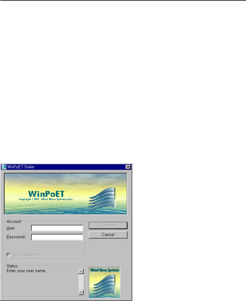
2.14 RFC 1483 (PPP over Ethernet) S/W Installation
The RFC 1483 doesn’t require Dial-Up Networking installation. You can use a
program provided by the Service Provider to connect to the Internet, or provided
WinPoET Program as follows.
1. Run WinPoET. And the following picture will come out. Just put in your User ID
and password.
2. If connection is successful, the following red-circled icon will come out
and you may double click to check connection status. In order to connect
with Internet, you may execute WinPoET.

GARNET GAE-3030
17
☞ WinPoET support all Windows 9x, NT and 2000.
Chapter 3. Appendix
3.1 Connector Specifications
3.1.1 H1 - RS232 Port
RS232 9-pin female D-connector transceiver port.
Pin Description Pin Description
1 Data carrier detect
2 Transmit data
3 Receive data
4 Data terminal ready
5 Ground (0v)
6 Data set ready
7 Request to send
8 Clear to send
9 Not connected
3.1.2 J2 – ADSL Port
RJ11 connector to connect to DSLAM or to PSTN
PinDescription
Pin Description
Pin Description
1 Transmit +
2 Transmit - 3 Not connected
4 Receive -
3.1.3 J3 - Ethernet Port
RJ45 type 10BaseT Ethernet connector. This connector is wired as an Ethernet
NIC.
Pin Description Pin Description
1 Transmit +
2 Transmit –
3 Receive +
4 Not connected
5 Not connected
6 Receive –
7 Not connected
8 Not connected

GARNET GAE-3030
18
3.2 WARRANTY
LIMITED WARRANTY
Garnet Systems warrants that the product will be free from defects in materials or workmanship for a
period of years from the date of purchase. Under this limited warranty, and upon proof of purchase, our
obligation is limited to repairing or replacing any product or parts proved to be defective at the inspection.
The product will be repaired or replaced (with the same or a s imilar model) at our option, without charge for
either parts or labor. This limited warranty shall not apply if the product is modified, tampered with, misused,
or subjected to abnormal working conditions (Including, but not limited to, lightning and water damage).
THIS LIMITED WARRANTY DOES NOT GUARANTEE YOU UNINTERRUPTED SERVICE. THE
FOREGOING REPAIR OR REPLACEMENT IS THE SOLE AND EXCLUSIVE REMEDY OF THE
PURCHASER, AND IS IN LIEU OF ALL OTHER WARRANTIES, EXPRESSED OR IMPLIED, OR
STATUTORY AS TO MERCHANTABILITY, FITNESS FOR PURPOSE SOLD, DESCRIPTION, QUALITY,
PRODUCTIVENESS OR ANY OTHER MATTER. WITHOUT LIMITING THE FOREGOING REPAIR OR
REPLACEMENT, IN NO EVENT SHALL GARNET SYSTEMS BE LIABLE FOR THE LOSS OF USE OR
PROFIT OR OTHER COLLATERAL, SPECIAL OR CONSEQUENTIAL DAMAGES.
To receive service under this limited warranty, contact Garnet Systems Co., Ltd. Myungsung Bldg., 145-7,
Dogok-dong, Kangnam -ku, Seoul, Korea (Zip Code 135-270), Technical Support Dept., at Tel : +82-2-
2188-7149, Fax : +82-2-529-8749 or visit the World Wide Web page at http://www.garnets.com or send
E-mail at sales@garnets.com . You will be given a Return Material Authorization (RMA) number so that
Garnet Systems Co., Ltd. may keep track of your limited warranty request.
Once you have received your RMA number, pack the product securely and send it, postage prepaid, to the
following address. Be sure that you include your RMA number, name and address on the shipping label as
well as inside the package.
Technical Support Department
RMA #
Garnet Systems Co., Ltd..
Myungsung Bldg., 145-7, Dogok-dong, Kangnam-ku, Seoul, Korea
Tel : +82-2-2188-7149, Fax : +82-2-529-8749, http://www.garnets.com, sales@garnets.com.

GARNET GAE-3030
19
3.3 Regulatory Information
Federal Communications Commission (FCC) Statements
This equipment has been tested and found to comply with the limits for a Class B digital device, pursuant
to Part 15 of the FCC Rules. These limits are designed to guarantee this device doesn’t harmfully interfere
with, or harmfully be interfered by other devices
Radio Frequency Interference Statement
Note : This equipment has been tested and found to comply with the limits for a Class B digital device,
pursuant to Part 15 of the FCC Rules. This equipment generates, uses and can radiate radio frequency
energy. If not installed and used in accordance with the instructions, may cause harmful interference to
radio communications.
The limits are designed to provide reasonable protection against such interference in a residential situation.
However, there is no guarantee that interference will not occur in a particular installation. If this equipment
does cause harmful interference to radio or television reception, which can be determined by turning the
equipment on and off, the user is encouraged to try to correct the interference by one or more of the
following measures:
- Reorient or relocate the receiving antenna of the affected radio or television
- Increase the separation between the equipment and the affected receiver
- Connect the equipment and the affected receiver to power outlets on separate circuits
- Consult the dealer or an experienced radio/TV technician for help.