Gateway 8450R Users Manual Server System
8450R to the manual 0bcf0d06-5753-4a89-9184-ba24f8effe95
2015-02-02
: Gateway Gateway-8450R-Users-Manual-403378 gateway-8450r-users-manual-403378 gateway pdf
Open the PDF directly: View PDF ![]() .
.
Page Count: 172 [warning: Documents this large are best viewed by clicking the View PDF Link!]
- Preface
- System Features
- System Setup
- Case Access
- Replacing and Adding Internal Devices
- Using the BIOS Setup Utility
- Managing the Server
- Troubleshooting
- Safety, Regulatory, and Notices
- System Specifications
- Index
A MAN US 8450R SYS GDE R0 6/00
8450R Server
System Manual
i
Contents
Preface...................................................v
Conventions used in this manual ....................................... v
Getting additional information . . ........................................vi
1 SystemFeatures ........................................7
Standardfeatures ...................................................7
Frontbezel.........................................................8
Front panel ........................................................9
Back panel ........................................................10
Systeminterior.....................................................11
System board .....................................................13
Hot-swapbackplane ................................................15
Front panel board . . ................................................16
Hot-plug PCI indicator board . . . .......................................17
2 SystemSetup .........................................19
Settinguptheserver ................................................19
Startingtheserver ..................................................20
Understanding the Power-On Self-Test ..............................21
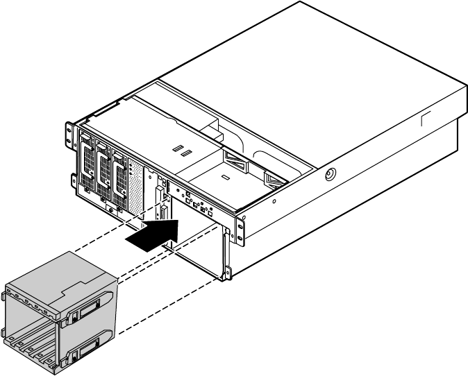
Settinguptheoperatingsystem....................................21
Turningofftheserver ...............................................22
Resettingtheserver ................................................23
3 CaseAccess ..........................................25
Preventingstaticelectricitydischarge ...................................25
Openingthecase ..................................................26
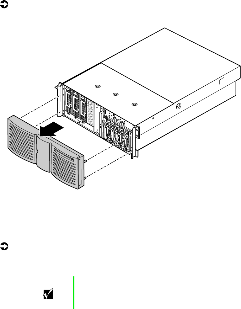
Opening the bezel door . . . .......................................27
Removingthebezel .............................................27
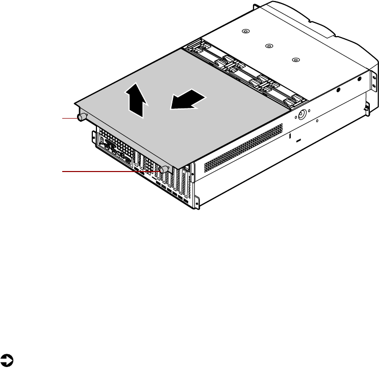
Removing the back top panel ......................................28
Removing the front top panel ......................................29
Closingthecase ...................................................31
Replacing the front top panel ......................................31
Replacingthebacktoppanel ......................................33
Replacingthebezel .............................................34
4 ReplacingandAddingInternalDevices....................35
Drives............................................................35
Preparing to replace or add a drive . . . ..............................35
8506284.book Page i Thursday, July 13, 2000 11:43 AM
ii
Drivecablinginformation ..........................................36
Removingahot-swapdrive ........................................36
Installingahot-swapdrive .........................................38
Replacingthehot-swapbackplane ..................................40
ReplacingtheCDdriveandthediskettedrive .........................45
Installinga5.25-inchdevice .......................................49
Replacinga5.25-inchdevice.......................................50
Memory ...........................................................52
Replacingmemory ...............................................52
Installingmemory ................................................57
Processors ........................................................61
Replacingaprocessor ............................................62
Installingaprocessor .............................................65
Replacingthebattery ................................................69
Expansion cards ....................................................73
Replacingahot-swapPCIcard .....................................73
Replacing an expansion card ......................................76
Addinganexpansioncard .........................................80
Power supplies .....................................................82
Hot-swapping a power supply module . . . .............................83
Replacing the power supply . . ......................................84
Fans .............................................................89
Replacingthefans ...............................................89
Replacing the fan power distribution board ............................90
Replacing the front panel board . . ......................................95
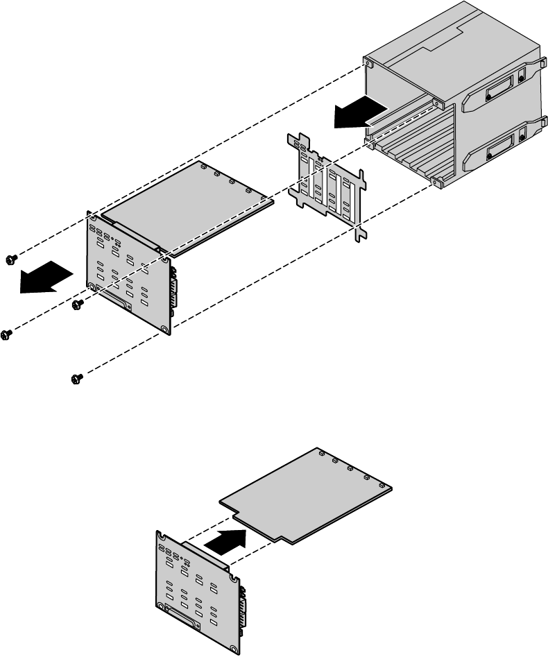
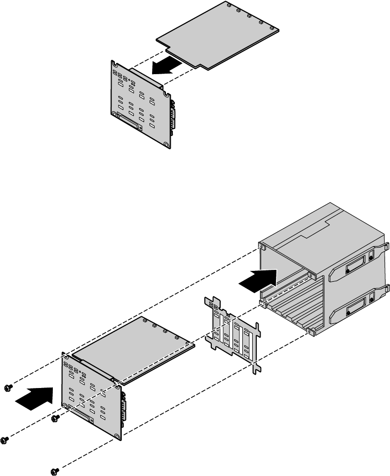
Replacing the hot-plug PCI indicator board . . .............................97
Replacing the system board ...........................................98
5 UsingtheBIOSSetupUtility ............................111
About the BIOS Setup utility ..........................................111
Updating the BIOS . . . ..............................................113
Settingthesystemboardjumpers .....................................114
TheCMOSClearjumper .........................................114
PasswordClearjumper ..........................................115
BOOTOptionjumper ............................................116
BIOSrecoverymode ............................................116
6 ManagingtheServer ...................................119
Avoidingpowersourceproblems ......................................119
Surge suppressors ..............................................119
Line conditioners . ..............................................120
Uninterruptible power supplies .....................................120
Maintaining and managing your hard drive . . ............................120
8506284.book Page ii Thursday, July 13, 2000 11:43 AM
iii
Hard drive maintenance utility ....................................120
Hard drive management practices .................................121
Protecting the server against viruses ..................................124
Systemadministrationandcontrol ....................................125
IntelServerControl(ISC) ........................................125
ManageX Event Manager . . ......................................125
DirectPlatformControl(DPC)Console .............................126
Systemsecurity................................................126
Systemrecovery ..................................................130
Creatingastartupdiskette .......................................130
Using your Server Companion CD .................................130
7 Troubleshooting ......................................131
Introduction ......................................................131
Troubleshooting checklist ...........................................131
Verifyingyourconfiguration ......................................131
Troubleshootingguidelines .......................................132
CDdriveproblems.................................................132
Diskettedriveproblems.............................................133
Harddriveproblems ...............................................134
Memoryandprocessorproblems .....................................134
Modem problems . . . ...............................................135
Peripheral/Adapter problems . . . ......................................136
Printerproblems ..................................................137
Systemproblems ..................................................138
Videoproblems ...................................................140
Error messages ...................................................142
A Safety,Regulatory,andNotices .........................147
B SystemSpecifications .................................161
Environmentalspecifications .........................................162
Index ..................................................163
8506284.book Page iii Thursday, July 13, 2000 11:43 AM
iv
8506284.book Page iv Thursday, July 13, 2000 11:43 AM

Conventions used in this manual v
Preface
Conventions used in this manual
Throughout this manual, you will see the following conventions:
Convention Description
ENTER Keyboard key names are printed in small capitals.
CTRL+ALT+DEL Aplussignmeanstopressthekeysatthesametime.
Setup Commands to be entered, options to select, and messages that
appear on your monitor are printed in bold.
User’s Guide Names of publications are printed in italic.
Viewpoint All references to front, rear, left, or right on the server are based
on the server being in a normal, upright position, as viewed from
the front.
Important A note labeled important informs you of special
circumstances.
Caution A caution warns you of possible damage to equipment or
loss of data.
Warning A warning indicates the possibility of personal injury.
8506284.book Page v Thursday, July 13, 2000 11:43 AM
vi Preface
Getting additional information
Log on to the Gateway technical support area at www.gatewayatwork.com to
find information about your system or other Gateway products. Some types
of information you can access are:
■Hardware driver and program updates
■Technical tips
■Service agreement information
■Technical documents and component information
■Frequently asked questions (FAQs)
■Documentation for peripherals or optional components
■Online technical support
8506284.book Page vi Thursday, July 13, 2000 11:43 AM

Standard features 7
1
System
Features
Standard features
■As many as four Intel® Pentium® III Xeon™ processors with 100 MHz
Front Side Bus (FSB) in Slot 2 processor sockets
■Sixteen Dual Inline Memory Module (DIMM) sockets on a memory riser
card, that support as many as 16 GB of PC100 Synchronous Dynamic
Random Access Memory (SDRAM)
■ServerWorks ServerSet™ IIIHE chipset
■Integrated Intel 82559 Fast Ethernet controller
■Integrated Adaptec AIC-7899 Dual-Channel Ultra/Ultra II/Ultra 160
(Ultra 3) small computer systems interface (SCSI) controller
■Integrated Adaptec AIC-7880 narrow/wide Ultra SCSI controller
■Integrated ATI Rage IIC video controller with 2 MB of SDRAM
■PCI hot-plug controller which supports six full-length, hot-pluggable PCI
slots
■Two half-length PCI slots
■Baseboard Management Controller (BMC) hardware management
■ATX form factor system board and dedicated rackmount chassis
■One 3.5 inch 1.44 MB diskette drive and one CD drive
■As many as five hot-swap SCSI hard drives
■Keyboard port (PS/2®), mouse port (PS/2), 2 serial ports, parallel port,
RJ-45 local area network (LAN) port, video port, and two Universal Serial
Bus (USB) ports
8506284.book Page 7 Thursday, July 13, 2000 11:43 AM
8System Features
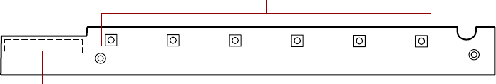
Front bezel
Bezel door provides access to the hot-swap drives and removable media
drives.
Front panel controls provide buttons for power, reset, and sleep, and
indicator lights for system fault, network activity, hard drive access, and
power. For more information on the controls, see “Front panel board” on
page 16.
Bezel door Front panel controls
8506284.book Page 8 Thursday, July 13, 2000 11:43 AM
Front panel 9
Front panel
Power supply supports as many as three hot-swap power supply modules.
5.25-inch drive bay supports one half-height 5.25-inch device.
Control panel contains the light emitting diode (LED) indicators and the
power, reset, and sleep buttons that control the server. For more information
on the controls, see “Front panel board” on page 16.
Hot-swap drive bay includes up to five hot-swappable drives connected to
a hot-swap backplane. The drive bays support 1.0-inch drives.
Hot-swap drives plug into the hot-swap drive bay.
Slimline diskette drive writes to and reads from 3.5-inch, 1.44 MB diskettes.
Slimline CD drive plays data or audio CDs.
Power supply modules provide N+1 redundant power (if all three modules
are installed).
Slimline
CD drive Slimline
diskette drive
Control panel
Hot-swap drives
Hot-swap drive bay
Power supply
modules
5.25-inch drive bayPower supply
8506284.book Page 9 Thursday, July 13, 2000 11:43 AM
10 System Features
Back panel
Expansion card slots (2) let you install as many as two 32-bit, 33 MHz PCI
expansion cards.
Hot-plug expansion card retention clips provide toolless installation of
hot-plug PCI cards.
Hot-plug expansion card slots (6) let you install as many as two 64-bit,
66 MHz hot-plug PCI expansion cards and as many as four 64-bit, 33 MHz
hot-plug PCI expansion cards.
Video port connects the first (or only) monitor interface cable. The video
controller is integrated in the system board.
USB ports connect external Plug-and-Play devices, such as printers, that are
automatically configured when they are plugged into the server through one
of these ports. USB keyboards and mice are not supported.
Network port lets you connect to a network. The adjacent indicator LEDs
show LAN activity (yellow) and 100 Mbit speed (green).
MOUSE PARALLEL
COM1 COM2
KEYBD
NETWORK
LAN
10/100
MB
ACT/
LINK USB 2
USB 1
VIEDO
Parallel port
Mouse
port
Expansion card slots
Power
connector
Keyboard port
Serial port A
Serial port B
Network port
Video port
USB ports Hot-plug expansion
card slots
Hot-plug expansion
card retention clips
8506284.book Page 10 Thursday, July 13, 2000 11:43 AM
System interior 11
Serial ports (2) connect to serial devices.
Parallel port connects a printer or other parallel device.
Keyboard port connects a PS/2-compatible keyboard.
Mouse port connects a PS/2-compatible mouse.
Power connector connects the server power cord. The other end of the power
cord plugs into an AC outlet or power strip.
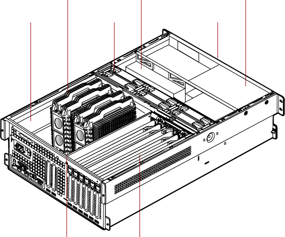
System interior
Electronics bay contains the system board, the processors, the memory, and
the expansion cards.
As many as four processors provide the processing power for the server.
Electronics bay
Processors
Fans
Hot-swap drive bay
Removable media
drives (not visible)
Power supply
Hot-swap PCI curtainsMemory card
(removed for clarity)
8506284.book Page 11 Thursday, July 13, 2000 11:43 AM
12 System Features
Fans provide cooling for all server components. There are as many as six
hot-swap fans in the server.
Hot-swap drive bays support up to five 1-inch high 3.25-inch single
connector attachment (SCA) SCSI hard drives. Empty drive bays contain
empty carriers to control airflow and electro-magnetic carrier (EMC)
emissions.
Removable media drives provide transportable storage for data. The server
supports one slimline CD drive, one slimline diskette drive, and one 5.25-inch
drive bay.
Power supply provides N+1 redundant power to the server components.
Hot-plug PCI curtains provide protection from electro-static discharge (ESD)
when installing or replacing hot-plug PCI cards. As many as four 64-bit,
33 MHz cards and as many as two 64-bit, 66 MHz PCI cards can be installed
between these curtains.
Memory card provides sixteen DIMM sockets and supports up to 16 GB of
SDRAM.
8506284.book Page 12 Thursday, July 13, 2000 11:43 AM
System board 13
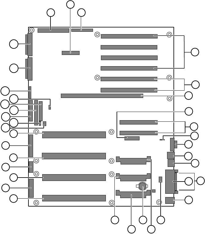
System board
ALegacy narrow SCSI connector
BServer monitor module (SMM) feature connector
CLegacy wide SCSI connector
D64-bit, 33 MHz hot-plug PCI expansion connectors
E64-bit, 66 MHz hot-plug PCI expansion connectors
FMemory module connector
AC
D
I
J
K
L
MN
O
P
Q
V
W
S
X
E
G
R
Y
Z
AA
B
F
H
T
U
AB AC
AD
AE
AF AG
AH
AI
AJ
8506284.book Page 13 Thursday, July 13, 2000 11:43 AM
14 System Features
GHot-plug indicator board connector
H32-bit, 33 MHz half-length PCI expansion connectors
IIntelligent chassis management bus (ICMB) connector
JVideo connector
KUSB connectors (2)
LRJ-45 Ethernet LAN connector and LEDs
MParallel port
NSerial ports
OStacked keyboard and mouse ports
PInternal USB connectors
QVoltage regulator module (VRM) socket (processor 2)
RBattery
SVRM socket (processor 4)
TVRM socket (processor 3)
UProcessor 4 connector
VMain ATX power 1 connector
WProcessor 3 connector
XATX auxiliary power connector
YProcessor 2 connector
ZMain ATX power 2 connector
AA Processor 1 connector
AB Hard drive activity connector
AC SMBus (system management bus) connector
AD Diskette drive connector
AE Integrated drive electronics (IDE) connector
AF Front panel connector
AG Intra Module Bus (IMB) connector
AH Configuration jumper J9F2 (pins 1-3: CMOS Clear, pins 5-7:
Password Clear, pins 9-11: Boot Option)
AI Ultra 160 SCSI A connector
AJ Ultra 160 SCSI B connector
8506284.book Page 14 Thursday, July 13, 2000 11:43 AM
Hot-swap backplane 15
Hot-swap backplane
Hot-swap SCSI indicator board connector connects the hot-swap indicator
board to the hot-swap backplane.
SCSI drive connectors (5) connect the five SCSI drives. Install drives in
increasing order of SCSI ID.
SCSI data connector connects the SCSI cable from the redundant array of
inexpensive drives (RAID) controller.
Power connectors connect the power cables from the power supply.
Fan connectors connect to dedicated fans for the hot-swap drive bay (not
used).
Fan
connectors
Power
connectors
SCSI data connector
Hot-swap SCSI indicator board connector
SCSI
ID 3
SCSI
ID 4 SCSI
ID 1
SCSI
ID 2 SCSI
ID 0
SCSI drive connectors (5)
8506284.book Page 15 Thursday, July 13, 2000 11:43 AM
16 System Features
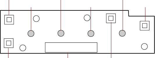
Front panel board
The front panel board supports the LEDs and buttons accessible from the front
panel. The buttons and LEDs on the front panel board are shown and
described below.
Reset button lets you reset the server if it has become nonresponsive.
system fault LED flashes whenever the server logs a failure.
Network activity LED lights whenever there is activity on the network.
Hard drive activity LED glows green whenever a hard drive is actively reading
or writing data and glows amber if a drive fails.
Power LED glows green whenever the server is turned on. The LED also flashes
when the server is in sleep mode.
Sleep button lets you put the server into sleep mode to reduce power
consumption.
Power button turns the server on and off.
Front panel connector connects the controls on the front panel with the
system board.
NMI switch allows a technician servicing the server to generate a
non-maskable interrupt (NMI) to help debug server errors.
Hard drive activity LED Sleep button
Front panel connector Power button
Network activity LED Power LEDReset button
System fault LED
NMI switch
8506284.book Page 16 Thursday, July 13, 2000 11:43 AM
Hot-plug PCI indicator board 17
Hot-plug PCI indicator board
The hot-plug PCI indicator board provides two LEDs per hot-plug PCI slot to
indicate the status of the board plugged into the slot.
Indicator LEDs indicate whether the hot-plug PCI slot is active or if it is safe
to replace the board in the indicated slot.
Data cable connector connects to the system board and carries the data
indicating which slots are active.
Indicator LEDs
Data cable connector
8506284.book Page 17 Thursday, July 13, 2000 11:43 AM
18 System Features
8506284.book Page 18 Thursday, July 13, 2000 11:43 AM

Settinguptheserver 19
2
System Setup
Settinguptheserver
Use the instructions on the quick guide poster that came with the server to
assemble the server.
You can prepare a safer working environment before assembling the server
by following these guidelines:
■Obtain an adequately rated uninterruptible power supply (UPS). A UPS
protects against AC line spikes, power interruptions, and other power
fluctuations that may damage the server.
■Protect the server from extreme temperature and humidity. Do not
expose it to direct sunlight, heater ducts, or other heat-generating objects.
■Keep the server away from equipment that generates magnetic fields,
such as unshielded stereo speakers. Even a telephone placed too close to
the server may cause interference.
■Plug the server into a wall outlet, power strip, or UPS.
Important Keep the boxes and packing material. If you need to send
the server to Gateway for repairs, you must use the original
packaging or your warranty may be voided.
8506284.book Page 19 Thursday, July 13, 2000 11:43 AM
20 System Setup
Starting the server
Before you start the server for the first time, make sure:
■The voltage selection switch is in the proper position. If the power supply
is autosensing, it will not have a voltage selection switch and it
automatically determines the voltage of the incoming power source.
■All cables are firmly connected to the proper ports on the back panel of
the server.
■The server and monitor are plugged into an AC outlet, power strip, or
UPS and that the power strip or UPS is turned on.
To start the server:
1If you have connected the system components to a power strip or UPS,
make sure all the system components are turned off, then turn on the
power strip or UPS.
2Turn on the monitor.
3Turn on the server. The LED on the control panel is lit when the power
is on.
4Turn on any other components connected to the server, such as speakers,
a printer, or a scanner.
If nothing happens when you turn on the server:
■Make sure that the power cables are securely plugged in and that
the power strip or UPS (if you are using one) is plugged in and
turned on.
■Make sure the monitor is connected to the server, plugged into the
power strip, AC outlet, or UPS, and turned on. You may also need
to adjust the brightness and contrast controls on the monitor.
Caution Electricity can flow from connected peripherals into the
server causing a shock. Make sure the server and
peripherals are turned off and unplugged from the power
outlet when you connect peripherals to the server.
8506284.book Page 20 Thursday, July 13, 2000 11:43 AM

Starting the server 21
Understanding the Power-On Self-Test
When you turn on your server, the power-on self-test (POST) routine checks
the server memory and components. To see this information on the screen,
press ESC during POST. Press SPACEBAR to bypass the remaining memory count.
The server displays an error message if POST finds any problems. Write down
any error messages that you see. If you continue to have problems, these error
messages may help you or Gateway technical support diagnose the cause.
Setting up the operating system
The first time you start the server, the operating system takes a few minutes
to set up.
Refer to your operating system documentation for specific questions regarding
the operating system.
To complete the operating system setup:
1After the server starts, the start-up wizard opens. Click Next.
2Type the requested information in the appropriate text boxes. When you
have finished typing the information, click Next.
3Continue following the instructions and selecting options in the start-up
wizard dialog boxes, clicking Next to move through the dialog boxes, until
the wizard tells you to restart your server.
If you need to return to the previous dialog box to change any of your
entries, click Back.
4Restart the server. The setup is complete.
Important For all operating systems, refer to the appropriate
operating system software manual for specific instructions.
8506284.book Page 21 Thursday, July 13, 2000 11:43 AM
22 System Setup
Turning off the server
Every time you turn off the server, shut down the operating system first. You
may lose data if you do not follow the proper procedure.
To turn off the server in Windows NT:
1Click Start, then select Shut down the computer?, then click Shut Down.
2Click OK. The operating system shuts down. When you see a message
sayingIt is now safe to turn off your computer, turn off the server by pressing
the power button.
3Turn off the monitor and peripherals.
Caution When you turn the server off, some electric current still
flows through it. Before opening the server case or
connecting or removing any peripherals, turn off the server,
then unplug the power cord.
Important For other operating systems, such as Windows 2000 or
Novell Netware, refer to the appropriate operating system
software manual for specific instructions.
8506284.book Page 22 Thursday, July 13, 2000 11:43 AM

Resetting the server 23
Resetting the server
If your server does not respond to keyboard or mouse input, you may have
to close programs that are not responding. If closing unresponsive programs
does not restore your server to normal operation, you may have to reset the
server.
To close unresponsive programs and reset the server in Windows NT:
1Press CTRL+ALT+DEL. A window opens that lets you close a program that
is not responding.
2Click Task Manager, then select the program that is not responding.
3Close the program by clicking End Task.
4If the server does not respond, press the reset button to restart the server.
As a part of the regular startup process, a program to check the disk status
runs automatically. When the checks are finished, Windows starts.
Important For other operating systems, such as Windows 2000 or
Novell Netware, refer to the appropriate operating system
software manual for specific instructions.
8506284.book Page 23 Thursday, July 13, 2000 11:43 AM
24 System Setup
8506284.book Page 24 Thursday, July 13, 2000 11:43 AM

Preventing static electricity discharge 25
3
Case Access
Preventing static electricity discharge
Before opening the server case, follow these precautions to prevent damage
from static electricity. When opening your server case, always perform the
following procedure.
To prevent static electricity discharge:
1Turn off the server.
2Touch a bare metal surface on the back of the server.
3Unplug all power cords from AC outlets and disconnect the modem cable
(if installed).
Also follow these static electricity precautions:
■Avoid static-causing surfaces such as plastic and packing foam in your
work area.
■Remove the parts from their antistatic bags or containers only when you
are ready to use them. Do not lay parts on the outside of an antistatic
bag or container because only the inside provides antistatic protection.
■Always hold cards by the edges and their metal mounting brackets. Avoid
touching components on the cards and the edge connectors that connect
to expansion slots. Never slide cards or other parts over any surface.
Caution Static electricity can permanently damage electronic
components in your server. Prevent electrostatic damage
to your server by following static electricity precautions
every time you open your server case.
8506284.book Page 25 Thursday, July 13, 2000 11:43 AM

26 Case Access
Opening the case
The only components that are accessible from the outside of the chassis are
the front panel controls and indicator lights, the hot-swap power supply
modules, the slimline diskette and CD drives, and the hot-swap hard drives.
To access the hot-swap drives, the removable media drives, or the front panel
you must open the bezel. To work on the internal components of the server,
you must open the chassis.
Because the components inside the server are extremely sensitive to static
electricity, make sure you follow the precautions at the beginning of this
chapter to avoid static electricity damage.
Only qualified personnel should open the server for maintenance. If you are
qualified to maintain the server yourself, make sure you are properly grounded
before opening the server chassis.
Important All references to front, back, left, or right on the server are
based on the server being in a normal, upright position,
as viewed from the front.
Caution Avoid exposure to dangerous electrical voltages and
moving parts by turning off your server and unplugging the
power cord and modem cable (if installed) before removing
the chassis cover.
8506284.book Page 26 Thursday, July 13, 2000 11:43 AM
Opening the case 27
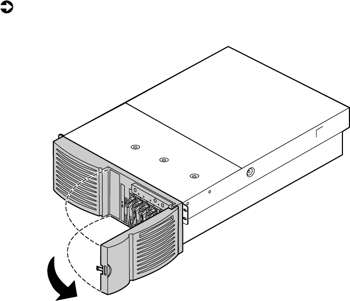
Opening the bezel door
The bezel door covers the removable media drives, the hot-swap drives, and
the front panel controls. To access these components, you must open the
bezel.
To open the bezel door:
1Grip the bezel door and pull the door straight out away from the chassis.
2Swing the door outward to the right.
Removing the bezel
The bezel covers the hot-swap power supply modules and the fasteners for
the removable media drives. You must remove the bezel to swap a power
supply module or replace a removable media device.
8506284.book Page 27 Thursday, July 13, 2000 11:43 AM
28 Case Access
To remove the bezel:
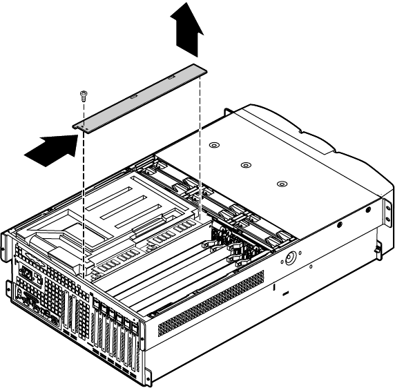
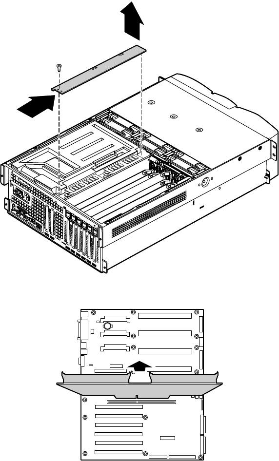
1Grip the bezel at both sides and pull it straight out from the front panel.
Removing the back top panel
The back top panel provides access to the hot-swap fans, the hot-swap PCI
slots, the memory card, the processors and VRMs, and the standard PCI slots.
To remove the back top panel:
1Observe all safety and static electricity precautions, see “Preventing static
electricity discharge” on page 25.
Important You do not have to turn off the server to open the back
top panel. However, do not remove the EMI foam from the
electronics bay unless you have turned the server off and
unplugged the power cord.
8506284.book Page 28 Thursday, July 13, 2000 11:43 AM
Opening the case 29
2Loosen the two thumbscrews from the top edge of the back panel.
3Slide the top panel slightly to the back, disengaging the front edge of
the panel from the front top panel.
4Lift the panel out and away from the chassis.
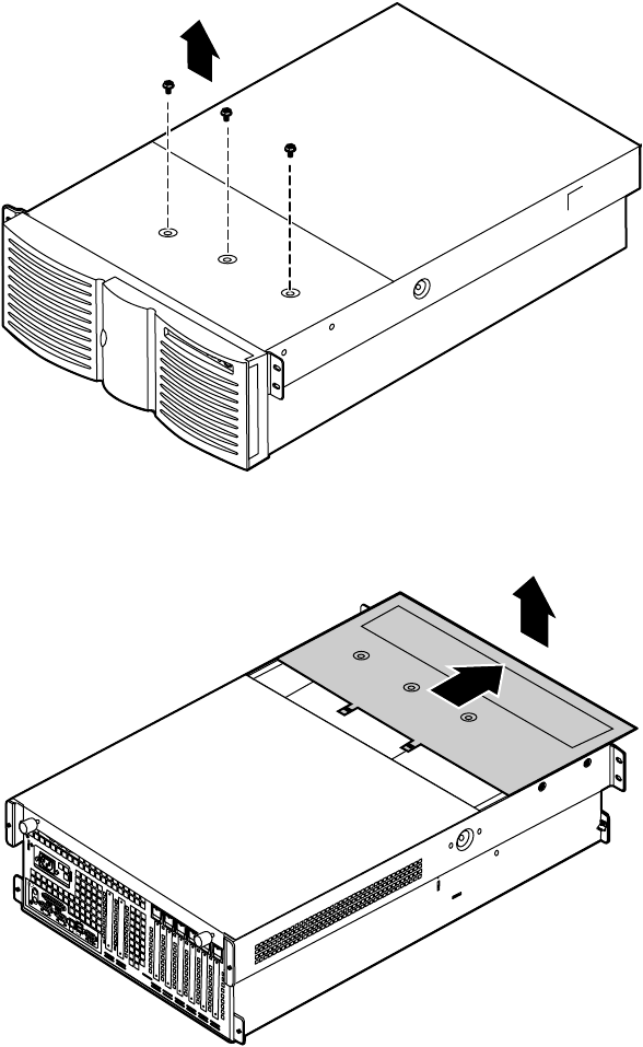
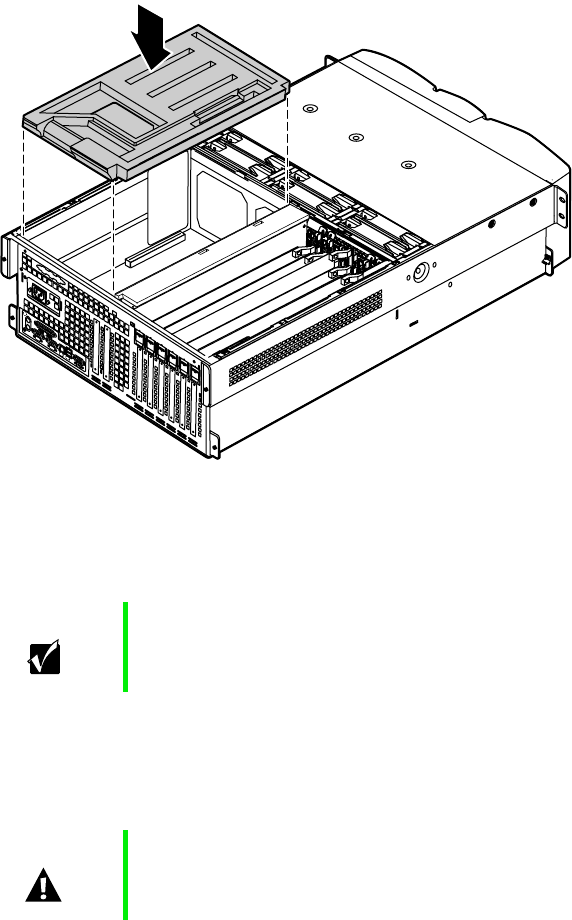
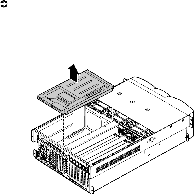
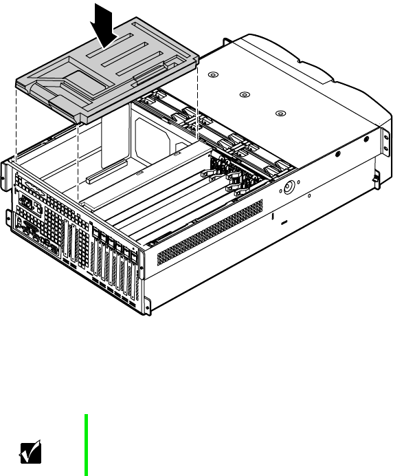
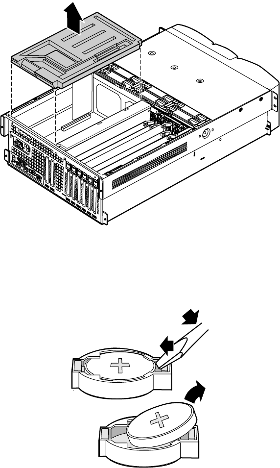
Removing the front top panel
The front top panel provides access to the hot-swap drive cage, the drive
cables, the power supply cables, and the front panel board.
To remove the front top panel:
1Turn off the server and disconnect all power cords.
2Observe all safety and static electricity precautions, see “Preventing static
electricity discharge” on page 25.
Thumbscrew
Thumbscrew
8506284.book Page 29 Thursday, July 13, 2000 11:43 AM
30 Case Access
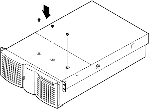
3Remove the three screws from the top of the front top panel.
4Slide the top panel slightly to the front, disengaging the back edge of
the panel from the top of the front panel.
5Lift the panel out and away from the chassis.
8506284.book Page 30 Thursday, July 13, 2000 11:43 AM
Closing the case 31
Closing the case
Close the chassis as soon as you finish installing or removing components
so that dust and dirt do not collect inside the server.
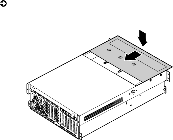
Replacing the front top panel
You can replace the front top panel whether the back top panel is on or off
of the chassis. You must replace the front top panel before you can operate
the server. If you do not, a system intrusion event is logged by the system
management hardware. Be careful not to pinch any cables with the panel as
you replace it.
To replace the front top panel:
1Place the front top panel on the top of the chassis approximately 3/4-inch
forward from the front of the server.
8506284.book Page 31 Thursday, July 13, 2000 11:43 AM
32 Case Access
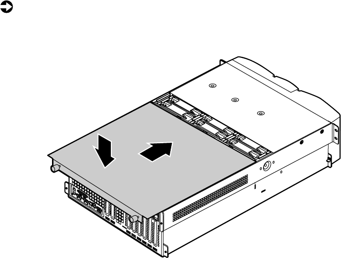
2Slide the panel toward the back of the chassis, securing it in place. The
tabs on the back edge of the front top panel slide under the lip of the
back top panel.
3Replace the screws you removed earlier.
8506284.book Page 32 Thursday, July 13, 2000 11:43 AM
Closing the case 33
Replacing the back top panel
To replace the back top panel:
1Place the back top panel on the top of the chassis approximately 3/4-inch
back from the back edge of the front top panel.
2Slide the panel toward the front of the chassis, securing it in place. Be
careful not to pinch any cables with the panel as you replace it.
3Tighten the thumbscrews you loosened earlier.
8506284.book Page 33 Thursday, July 13, 2000 11:43 AM
34 Case Access
Replacing the bezel
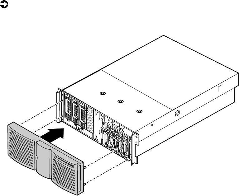
The bezel prevents unauthorized access to the hot-swap power supply modules
and the fasteners for the removable media drives.
To replace the bezel:
1Align the four pins on the back of the bezel with the four holes in the
sides of the front panel and press the bezel firmly into place.
8506284.book Page 34 Thursday, July 13, 2000 11:43 AM

Drives 35
4
Replacing and
Adding Internal
Devices
Drives
There are several types of drives and similar devices that can be installed in
the server.
Preparing to replace or add a drive
One 3.5-inch diskette drive, at least one 1-inch high 3.5-inch hot-swap hard
drive, and one slimline CD drive are included with the server. You can add
up to four additional 3.5-inch hot-swap drives for a total of five hot-swap
drives. You may also add one 5.25-inch device.
As you prepare to install drives, keep the following in mind:
■If you remove a drive, place it in an antistatic bag or container.
■Before you install a drive, see the drive documentation for information
on configuring the drive, setting any jumpers on the drive, and attaching
cables to the drive.
■If you are installing a drive that uses an add-in controller, install the
expansion card before you install the drive.
■You may need to configure the drives you install using the BIOS (Basic
Input/Output System) Setup utility or the SCSISelect utility. Press F2 at
start up to open the BIOS Setup utility or press CTRL+A to enter the
SCSISelect utility.
8506284.book Page 35 Thursday, July 13, 2000 11:43 AM

36 Replacing and Adding Internal Devices
Drive cabling information
The server includes four different types of drive cables. Each drive cable is
clearly labeled, indicating the cable type and showing which end to connect
to the appropriate connector on the system board and which end to connect
to the drive.
■Use the diskette drive connector cable to connect the diskette drive.
■Use the standard IDE connector cable to connect the CD drive and an
IDE device installed in the 5.25-inch drive bay to the system board.
■Use a narrow SCSI cable to connect a legacy narrow SCSI device in the
5.25-inch drive bay to the legacy narrow SCSI controller integrated onto
the system board
■Use the SCSI low-voltage differential (LVD) cable to connect the hot-swap
backplane to the integrated SCSI controller on the system board.
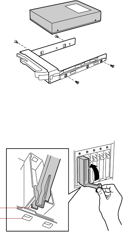
Removing a hot-swap drive
The hot-swap drives are located at right side of the front panel. The hot-swap
drive bay supports as many as five, 1-inch high 3.5-inch SCSI hard drives.
The hot-swap drives are assigned SCSI ID numbers by the hot-swap backplane
with the drive on the right end of the hot-swap bay assigned SCSI ID 0. The
backplane assigns SCSI IDs to the other drives in order up to SCSI ID 4 on
the left end of the hot-swap bay. See “Hot-swap backplane” on page 15 for
the locations of the drives by SCSI ID number.
Install the first drive at the right end, then install drives in increasing order
by SCSI ID number thereafter. You do not need to turn off the server before
you remove or replace a hot-swap drive.
Important Gateway tests and verifies the operation and compatibility
of the drives we sell. Additional or replacement drives must
conform to Gateway standards, especially in a RAID or
mission-critical environment.
8506284.book Page 36 Thursday, July 13, 2000 11:43 AM
Drives 37
To remove a hot-swap drive:
1Follow the static electricity precautions in “Preventing static electricity
discharge” on page 25.
2Use the SCSI control software to stop activity on the drive you need to
remove.
3Open the bezel door as described in “Opening the bezel door” on page 27.
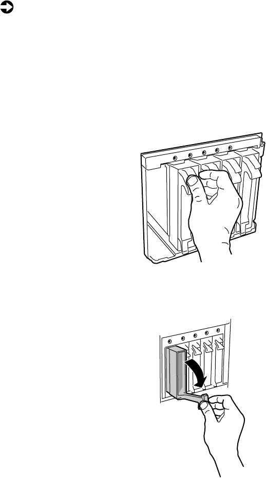
4Pinch the grip of the drive carrier handle to release the clip at the top.
5Swing the carrier handle down and pull the drive out of the drive cage.
Continue pulling until the drive is entirely out of the drive cage.
6Place the drive on a static-free surface. If you are replacing the drive, see
“Installing a hot-swap drive” on page 38.
8506284.book Page 37 Thursday, July 13, 2000 11:43 AM
38 Replacing and Adding Internal Devices
Installing a hot-swap drive
If you are adding a drive to an empty drive slot, you must first remove the
air baffles from the drive carrier. If you are replacing an existing drive, remove
the old drive as described in “Removing a hot-swap drive” on page 36.
To install a hot-swap drive:
1Follow the static electricity precautions in “Preventing static electricity
discharge” on page 25.
2Remove the drive carrier as described in “Removing a hot-swap drive”
on page 36.
3Remove the four screws that secure the air baffles to the drive carrier. If
you are removing an existing drive, the same four screws secure the old
drive to the carrier.
8506284.book Page 38 Thursday, July 13, 2000 11:43 AM
Drives 39
4Use the four screws you removed in Step 3 to secure the new drive to
the drive carrier.
5With the drive carrier handle in the open position, align the drive carrier
rails with the grooves at the top and bottom of the drive bay.
6Slide the drive into the bay until the handle starts to close. Make sure
the tab on the bottom of the handle fits into the slot on the bottom of
the drive cage.
7Close the handle securely to set the drive connector into the connector
at the back of the drive cage.
8Close the bezel door.
9Use the SCSI control utility to format and configure the new drive.
Tab
Slot
8506284.book Page 39 Thursday, July 13, 2000 11:43 AM
40 Replacing and Adding Internal Devices
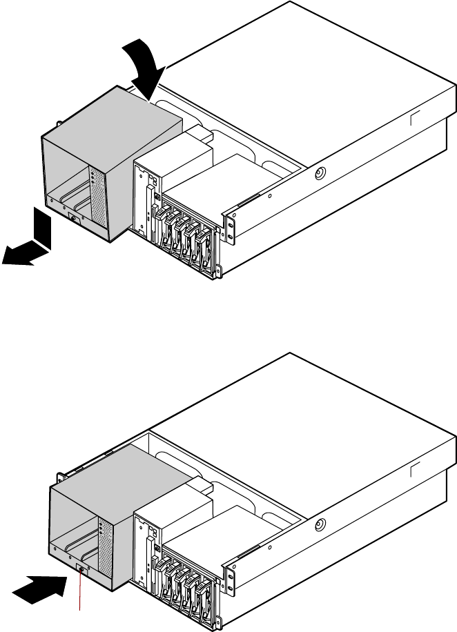
Replacing the hot-swap backplane
The hot-swap drive bay indicator board comes out of the server with the
hot-swap backplane. This procedure removes both boards from the sever.
You should only replace the hot-swap backplane if Gateway Client Care has
instructed you to do so. The hot-swap drive cage fits very tightly in the chassis
and you may need the assistance of a second technician to remove it.
To replace the hot-swap backplane:
1Follow the static electricity precautions in “Preventing static electricity
discharge” on page 25.
2Turn off the server and disconnect the power cord and all other external
peripheral devices.
3Remove the front top panel as described in “Removing the front top
panel” on page 29.
4Disconnect all cables from the drive cage and the backplane.
5Remove all of the hot-swap drive carriers from the hot-swap drive cage
as described in “Removing a hot-swap drive” on page 36.
6Using a flat-bladed screwdriver or similar tool, press the plastic tabs on
both sides of the drive cage toward the center of the cage. You may need
to hold them in on one side while pressing them in on the other.
8506284.book Page 40 Thursday, July 13, 2000 11:43 AM
Drives 41
7When you have freed all four tabs, push the drive cage out from the back,
then pull it out of the chassis.
8506284.book Page 41 Thursday, July 13, 2000 11:43 AM
42 Replacing and Adding Internal Devices
8Remove the four screws that secure the hot-swap backplane to the
hot-swap drive cage, then pull the backplane out of the drive cage. The
hot-swap indicator board will also come out of the drive cage.
9Remove the hot-swap indicator board and the plastic shield from the
hot-swap backplane and place both boards on a static-free surface.
8506284.book Page 42 Thursday, July 13, 2000 11:43 AM
Drives 43
10 Plug the hot-swap indicator board into the new hot-swap backplane.
11 Put the plastic shield into place and carefully insert the two boards into
the hot-swap drive cage
8506284.book Page 43 Thursday, July 13, 2000 11:43 AM
44 Replacing and Adding Internal Devices
12 Secure the hot-swap backplane in placed with the four screws you
removed in Step 8.
13 Align the four rails on the sides of the drive cage with the grooves in
the chassis and slide the hot-swap drive cage back into the chassis.
14 Install all of the hot-swap drive carriers as described in “Installing a
hot-swap drive” on page 38.
15 Reconnect the cables to the hot-swap backplane.
16 Replace the front top panel as described in “Replacing the front top
panel” on page 31.
17 Plug in the peripherals and the power cord and turn on the server.
8506284.book Page 44 Thursday, July 13, 2000 11:43 AM
Drives 45
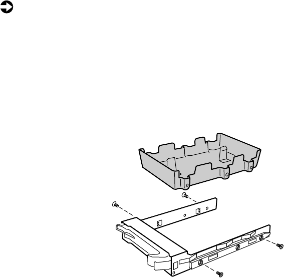
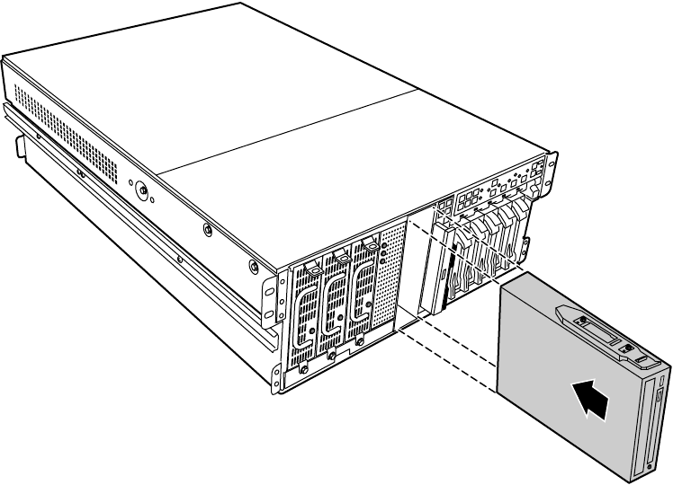
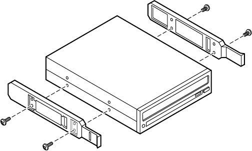
Replacing the CD drive and the diskette drive
The slimline CD drive and the slimline diskette drive are near the center of
the front panel. See “Front panel” on page 9 for the location of the slimline
diskette drive and slimline CD drive.
To replace the slimline CD drive and the slimline diskette drive:
1Turn off the server and disconnect the power cord and all other external
peripheral devices.
2Remove the front top panel. (See “Removing the front top panel” on
page 29 and “Preventing static electricity discharge” on page 25.)
3Remove the power and data cables from the back of the slimline diskette
drive and the slimline CD drive, noting their locations and orientations.
(You will reconnect these cables after you install the new drive.)
4Remove the diskette drive tray by removing the screw from the front
panel.
5Pull the tray out of the chassis.
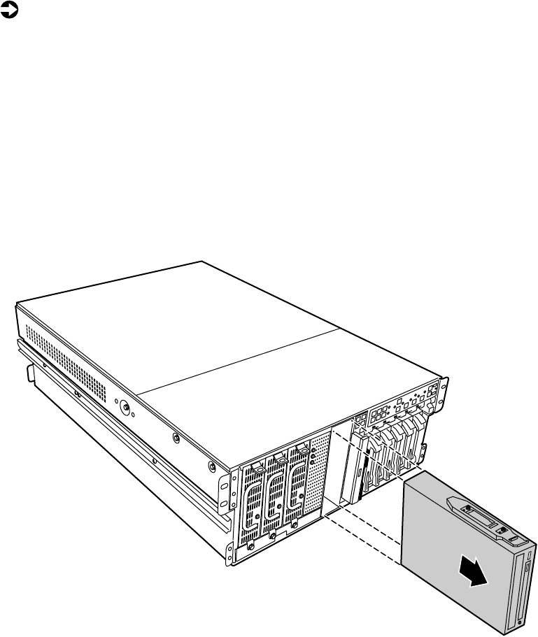
8506284.book Page 45 Thursday, July 13, 2000 11:43 AM
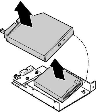
46 Replacing and Adding Internal Devices
6Pull the top (right) edge of the CD drive free from the clips holding it
in place.
7Pull the top (right) edge of the diskette drive free from the tray in the
same manner.
8If necessary, set any jumpers on the new diskette drive. (See your drive
documentation for proper drive jumper settings and cable orientation.)
8506284.book Page 46 Thursday, July 13, 2000 11:43 AM
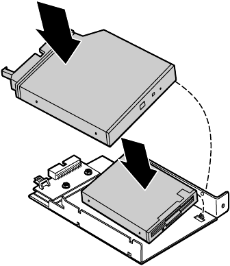
Drives 47
9Align the holes on the bottom (left) edge of the diskette drive with the
pins on the drive tray and press the diskette drive firmly in place.
10 Align the holes on the bottom (left) edge of the CD drive with the pins
on the drive tray and press the CD drive firmly into place.
8506284.book Page 47 Thursday, July 13, 2000 11:43 AM
48 Replacing and Adding Internal Devices
11 Replace the tray in the chassis using the screw you removed in Step 4 to
secure the tray in position.
12 Connect the power and data cables, making sure the cables are in their
original positions.
13 Close the case. (See “Closing the case” on page 31.)
14 Reconnect the power cord and all other external peripheral devices, then
turn on the server.
8506284.book Page 48 Thursday, July 13, 2000 11:43 AM
Drives 49
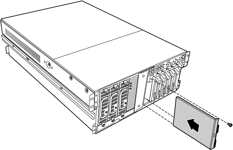
Installing a 5.25-inch device
The chassis supports a single half-height 5.25-inch device. The 5.25-inch drive
bay is in the center of the front panel (see “System board” on page 13.)
To install a 5.25-inch device:
1Turn off the server and disconnect the power cord and all other external
peripheral devices.
2Remove the bezel. (See “Removing the bezel” on page 27.)
3Remove the front top panel. (See “Removing the front top panel” on
page 29 and “Preventing static electricity discharge” on page 25.)
4Pull out the metal electro-magnetic interference (EMI) shield from the
front of the 5.25-inch drive bay and save it in case you need to remove
the 5.25-inch device you are installing.
5Install the drive rails on the 5.25-inch device. (See the documentation
that came with the device for any jumper settings and cable orientation
information.)
8506284.book Page 49 Thursday, July 13, 2000 11:43 AM
50 Replacing and Adding Internal Devices
6Align the drive rails with the grooves at the top and bottom of the
5.25-inch drive bay and slide the device into the bay until the rails click
into place.
7Connect power and data cables to the device, making sure the cables are
oriented correctly.
8Close the case. (See “Closing the case” on page 31.)
9Reconnect the power cord and all other external peripheral devices, then
turn on the server.
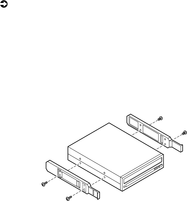
Replacing a 5.25-inch device
The chassis supports a single half-height 5.25-inch device. The 5.25-inch drive
bay is in the center of the front panel. If you remove a device from the
5.25-inch drive bay, you must either install a replacement device or install
the metal EMI shield that originally shipped with the server.
8506284.book Page 50 Thursday, July 13, 2000 11:43 AM
Drives 51
To replace a 5.25-inch device:
1Turn off the server and disconnect the power cord and all other external
peripheral devices.
2Remove the bezel. (See “Removing the bezel” on page 27.)
3Remove the front top panel. (See “Removing the front top panel” on
page 29 and “Preventing static electricity discharge” on page 25.)
4Disconnect the power and data cables from the device. If you intend to
install a replacement device, note the location and orientation of the
cables to make installing the replacement device easier.
5Pinch the front ends of the drive rails toward the center of the drive bay,
and pull the drive out of the bay.
8506284.book Page 51 Thursday, July 13, 2000 11:43 AM
52 Replacing and Adding Internal Devices
6Remove the drive rails from the device by removing the four screws that
hold them in place.
7If you are installing a replacement device, install the rails on the device
and proceed from Step 5 on page 49.
8If you are not installing a replacement device, re-install the metal EMI
shield you removed when you originally installed the 5.25-inch device.
9Close the case. (See “Closing the case” on page 31.)
10 Reconnect the power cord and all other external peripheral devices, then
turn on the server.
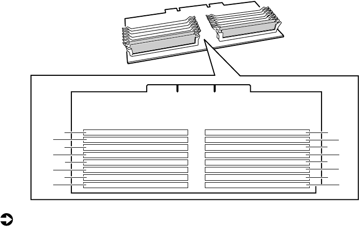
Memory
Sixteen DIMM sockets on the separate memory board support up to
16.0 Gigabytes (GB) of PC/100 SDRAM.
Replacing memory
The SDRAM DIMMs supported by your system board conform to the following
standards:
■64 MB, 128 MB, 256 MB, 512 MB, and 1 GB Error Checking and
Correcting (ECC) DIMMs
■PC100-compliant, registered, parity, ECC SDRAM
8506284.book Page 52 Thursday, July 13, 2000 11:43 AM
Memory 53
When you select and install DIMMs, keep the following in mind:
■Registered DIMMs should not be combined with unbuffered DIMMs.
■Memory must be installed in complete banks (four DIMMs at a time),
from bank A to bank D.
■No jumper settings are required for the memory size or type because the
BIOS automatically detects this information.
■16 GB maximum system memory.
Memory banks are arranged as shown in the figure below.
To replace DIMMs:
1Turn off the server and disconnect the power cord and all other external
peripheral devices.
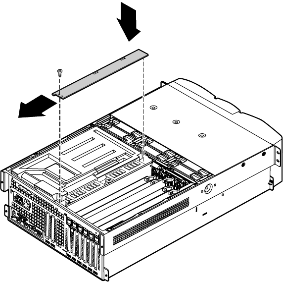
2Remove the back top panel. (See “Removing the back top panel” on
page 28 and “Preventing static electricity discharge” on page 25.)
C3
D3
C1
D1
C4
D4
C2
D2
A3
B3
A1
B1
A4
B4
A2
B2
8506284.book Page 53 Thursday, July 13, 2000 11:43 AM
54 Replacing and Adding Internal Devices
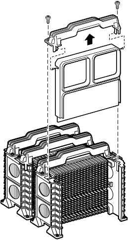
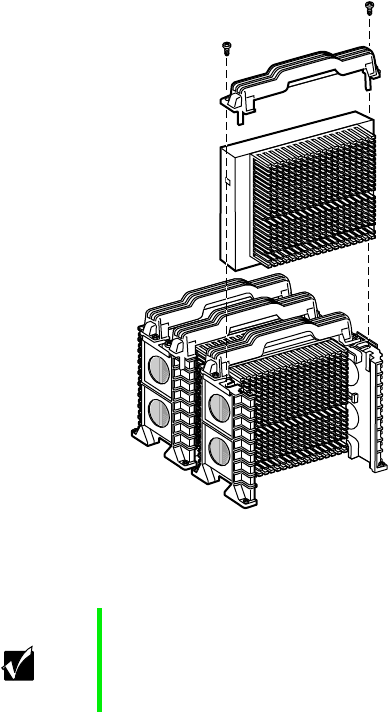
3Remove the memory board retention bracket by removing the screw at
the back end, sliding the bar to the front, and lifting the bracket out of
the slot on the edge of the electronics bay.
8506284.book Page 54 Thursday, July 13, 2000 11:43 AM
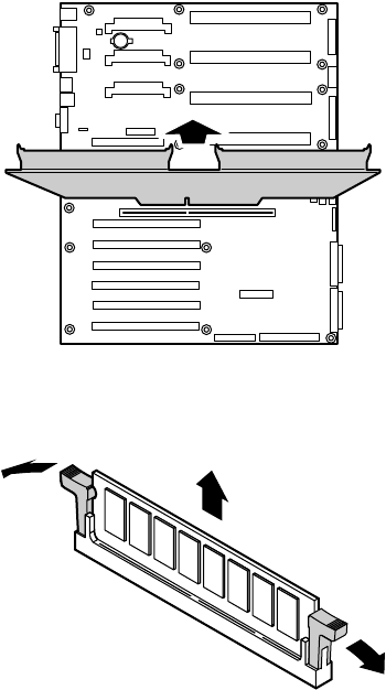
Memory 55
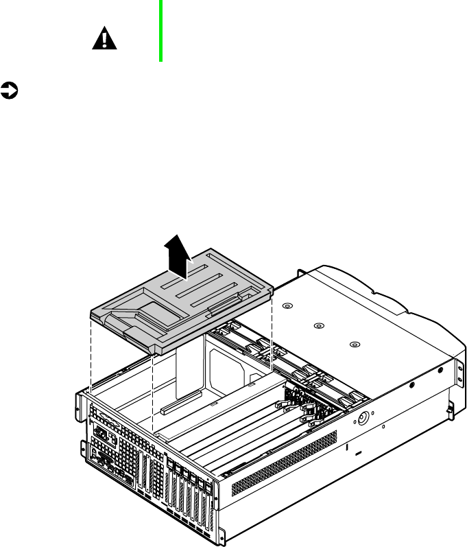
4Pull the memory board out of the chassis and place it on a static-free
surface.
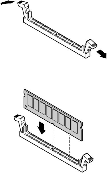
5Pull open the socket clamps on each side of the DIMM socket, then lift
the DIMM out of the socket. Store the DIMM in an anti-static container.
Boards shown outside
chassis for clarity
8506284.book Page 55 Thursday, July 13, 2000 11:43 AM
56 Replacing and Adding Internal Devices
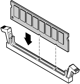
6Insert the new DIMM into the socket, aligning the two notches in the
DIMM with the two notches in the DIMM socket.
7Gently press the DIMM into the socket until it is firmly seated. Inserting
the DIMM automatically locks the socket clamps on each end of the
DIMM.
8Once all DIMMs have been installed, replace the memory board in the
server.
8506284.book Page 56 Thursday, July 13, 2000 11:43 AM

Memory 57
9Replace the memory board retention bracket, hooking the tab over the
edge of the electronics bay and replacing the screw in the back panel.
10 Close the case. (See “Closing the case” on page 31.)
11 Reconnect the peripherals and the power cord, then turn on the server.
Installing memory
The SDRAM DIMMs supported by your system board conform to the following
standards:
■64 MB, 128 MB, 256 MB, 512 MB, and 1 GB ECC DIMMs
■PC100-compliant, registered, parity, ECC SDRAM
8506284.book Page 57 Thursday, July 13, 2000 11:43 AM

58 Replacing and Adding Internal Devices
When you select and install DIMMs, keep the following in mind:
■Registered DIMMs should not be combined with unbuffered DIMMs.
■Memory must be installed in complete banks (four DIMMs at a time),
from bank A to bank D.
■No jumper settings are required for the memory size or type because the
BIOS automatically detects this information.
■16 GB maximum system memory.
Memory banks are arranged as shown in the figure below.
To add DIMMs:
1Turn off the server and disconnect the power cord and all other external
peripheral devices.
2Remove the back top panel. (See “Removing the back top panel” on
page 28 and “Preventing static electricity discharge” on page 25.)
C3
D3
C1
D1
C4
D4
C2
D2
A3
B3
A1
B1
A4
B4
A2
B2
8506284.book Page 58 Thursday, July 13, 2000 11:43 AM
Memory 59
3Remove the memory board retention bracket by removing the screw at
the back end, sliding the bar forward, and lifting the bracket out of the
slot on the edge of the electronics bay.
4Pull the memory card out of the chassis and put it on a static-free surface.
Boards shown outside
chassis for clarity
8506284.book Page 59 Thursday, July 13, 2000 11:43 AM
60 Replacing and Adding Internal Devices
5Pull open the socket clamps on each side of the DIMM socket.
6Insert the new DIMM into the socket, aligning the two notches in the
DIMM with the two notches in the DIMM socket.
7Gently press the DIMM into the socket until it is firmly seated. Inserting
the DIMM automatically locks the socket clamps on each end of the
DIMM.
8Once all DIMMs have been installed, replace the memory board in the
server.
8506284.book Page 60 Thursday, July 13, 2000 11:43 AM
Processors 61
9Replace the memory board retention bracket, hooking the tab over the
edge of the electronics bay and replacing the screw in the back panel.
10 Close the case. (See “Closing the case” on page 31.)
11 Reconnect the peripherals and the power cord, then turn on the server.
Processors
The server is compatible with the Intel® Pentium®III 550 MHz and faster
processors with 100MHz FSB. As many as four processors may be installed
in the server (they must have the same processor and FSB speed). Processor
and FSB speed are automatically detected by the server. Processors must be
installed in order, from slot 1 through slot 4 and a VRM must be installed
for each processor added to the server. Whenever processors are installed, the
most current version of the BIOS should be installed as well (see “Updating
the BIOS” on page 113).
8506284.book Page 61 Thursday, July 13, 2000 11:43 AM
62 Replacing and Adding Internal Devices
Replacing a processor
When replacing a processor, order a processor upgrade kit from Gateway.
To replace a processor:
1Turn off the server and disconnect the power cord and all external
peripheral devices.
2Remove the back top panel. (See “Preventing static electricity discharge”
on page 25 and “Removing the back top panel” on page 28.)
3Remove the EMI foam cover over the processors.
Caution A heatsink must be installed on each processor. Installing
a processor without a heatsink could result in damage to,
or failure of, the processor.
8506284.book Page 62 Thursday, July 13, 2000 11:43 AM

Processors 63
4Using a phillips screwdriver, remove the two screws that hold the
processor retention bracket in place.
5Pull the processor up and out of the slot.
6If the heatsink is separate, attach it to the processor.
8506284.book Page 63 Thursday, July 13, 2000 11:43 AM
64 Replacing and Adding Internal Devices
7Align the new processor with the processor slot (note that the processor
slot is keyed so the processor can only be installed one way) and press
firmly to install it.
8Replace the processor support bracket using the two screws you removed
in Step 4.
8506284.book Page 64 Thursday, July 13, 2000 11:43 AM
Processors 65
9Replace the EMI foam in the same orientation it was in when you
removed it.
10 Close the case. (See “Closing the case” on page 31.)
11 Reconnect the power cord and all other cords you removed, then turn
on the server.
Installing a processor
When replacing a processor, order a processor upgrade kit from Gateway.
Important Gateway recommends that you run a processor retest from
the BIOS Setup utility whenever you replace or add a
processor.
Caution A heatsink must be installed on each processor. Installing
a processor without a heatsink could result in damage to,
or failure of, the processor.
8506284.book Page 65 Thursday, July 13, 2000 11:43 AM
66 Replacing and Adding Internal Devices
To add a second (or later) processor:
1Turn off the server and disconnect the power cord and all external
peripheral devices.
2Remove the back top panel. (See “Preventing static electricity discharge”
on page 25 and “Removing the back top panel” on page 28.)
3Remove the EMI foam cover over the processors.
8506284.book Page 66 Thursday, July 13, 2000 11:43 AM
Processors 67
4Using a phillips screwdriver, remove the two screws that secure the
processor retention bracket, then remove the terminator card from the
processor slot you want to install the new processor in.
5If the heatsink is separate, attach it to the new processor.
8506284.book Page 67 Thursday, July 13, 2000 11:43 AM
68 Replacing and Adding Internal Devices
6Align the new processor with the processor slot. Note that the processor
slot is keyed so the processor can only be installed one way. Press it firmly
to install it.
7Secure the new processor with the processor retention bracket and the
two screws you removed earlier.
Important As originally shipped, the system board has all of the
VRMs necessary to support a full complement of
processors. If you need to replace any of the VRMs, you
must install one VRM for each processor except the first.
8506284.book Page 68 Thursday, July 13, 2000 11:43 AM
Replacing the battery 69
8Replace the EMI foam in the same orientation it was in when you
removed it.
9Close the case. (See “Closing the case” on page 31.)
10 Reconnect the power cord and all other cords you removed, then turn
on the server.
Replacing the battery
The battery provides power for the server clock and CMOS memory, which
holds the system configuration information.
If your battery is failing you may notice the server clock slowing down and
giving you the incorrect time.
Important Gateway recommends that you run a processor retest from
the BIOS Setup utility whenever you replace or add a
processor.
8506284.book Page 69 Thursday, July 13, 2000 11:43 AM
70 Replacing and Adding Internal Devices
Open the BIOS Setup utility and write down all the values in the various
menus before replacing the battery. Replacing the battery resets the BIOS Setup
utility to its default values.
To replace the battery:
1Restart the server and start the BIOS Setup utility.
2Write down the CMOS values from each tab in the BIOS Setup utility so
you can reenter them after you replace the battery. For more information
about the BIOS Setup utility, see “About the BIOS Setup utility” on
page 111.
3Turn off the server, disconnect the power cord and all external peripheral
devices.
4Remove the back top panel. (See “Removing the back top panel” on
page 28 and “Preventing static electricity discharge” on page 25.)
Warning There is a danger of explosion if the battery is incorrectly
replaced.
Replace only with the same or equivalent type
recommended by the manufacturer.
Dispose of used batteries according to the manufacturer’s
instructions.
Warnung Explosionsgefahr bel falsch eingebautter batterie.
Ersetzen der batterien nur mit batterien des gleichen typs
oder mit batterien vom hersteller empfohlenen typs.
Entsorgen gebrauchter batterien entsprechned
herstellerangaben.
Attention Il y a danger d’explosion s’il y a replacement incorrect de
la batterie.
Remplacer uniquement avec une batterie du même type
ou d’un type équivalent recommandé par le constructeur.
Mettre au rebut les batteries usagées conformément aux
instructions du fabricant.
8506284.book Page 70 Thursday, July 13, 2000 11:43 AM
Replacing the battery 71
5Remove the EMI foam cover over the processors.
6Locate the battery on the system board (see “System board” on page 13).
The battery is circular and has the positive pole mark (+) on the top.
7Using a small, flat-bladed screwdriver, carefully remove the battery from
its socket on the system board.
1
2
3
8506284.book Page 71 Thursday, July 13, 2000 11:43 AM

72 Replacing and Adding Internal Devices
8Press the new battery in the socket with the positive pole up. Be sure you
press the battery down far enough for it to contact the base of the socket
(it should snap into place).
9Replace the EMI foam in the same orientation it was in when you
removed it.
10 Close the case, as described in “Closing the case” on page 31.
11 Reconnect the peripherals and the power cord, then turn on the server.
12 If the CMOS data is not correct, change the information in the BIOS Setup
utility using the data you recorded in Step 2.
Troubleshooting the battery installation
If you have problems after installing the new battery, try each of the items
listed below.
■Turn off the server and make sure that all exterior cables are attached
and secured to the correct connectors.
■Make sure that all power switches are on. If the server is plugged into a
power strip or surge protector, make sure it is turned on.
8506284.book Page 72 Thursday, July 13, 2000 11:43 AM

Expansion cards 73
■Enter the BIOS Setup utility and compare the settings on the screen with
your notes or the server hardware manuals. Correct any discrepancies
then save the changes and restart the server.
■Turn off the server, remove the cover, and make sure that all cables inside
the case are attached securely. Also, make sure that the colored cable edges
are aligned correctly and that the connectors did not miss any pins.
Disconnect and reconnect the cables. Close the case as described in
“Closing the case” on page 31, reconnect the modem and power cords,
then turn on the server.
■Turn off the server, remove the cover and, if you have the proper test
equipment, make sure that the new battery has power. (Although
unlikely, your new battery may be defective.) Close the case as described
in “Closing the case” on page 31, reconnect the power cord, then turn
on the server.
Expansion cards
The server supports two 32-bit, 33 MHz PCI cards. Both slots support
half-length cards. In addition, the server supports six full-length, hot-swap PCI
cards. Two of these cards can be 64-bit, 66 MHz cards and four can be 64-bit,
33 MHz cards. See “System board” on page 13 for the locations of the card
slots.
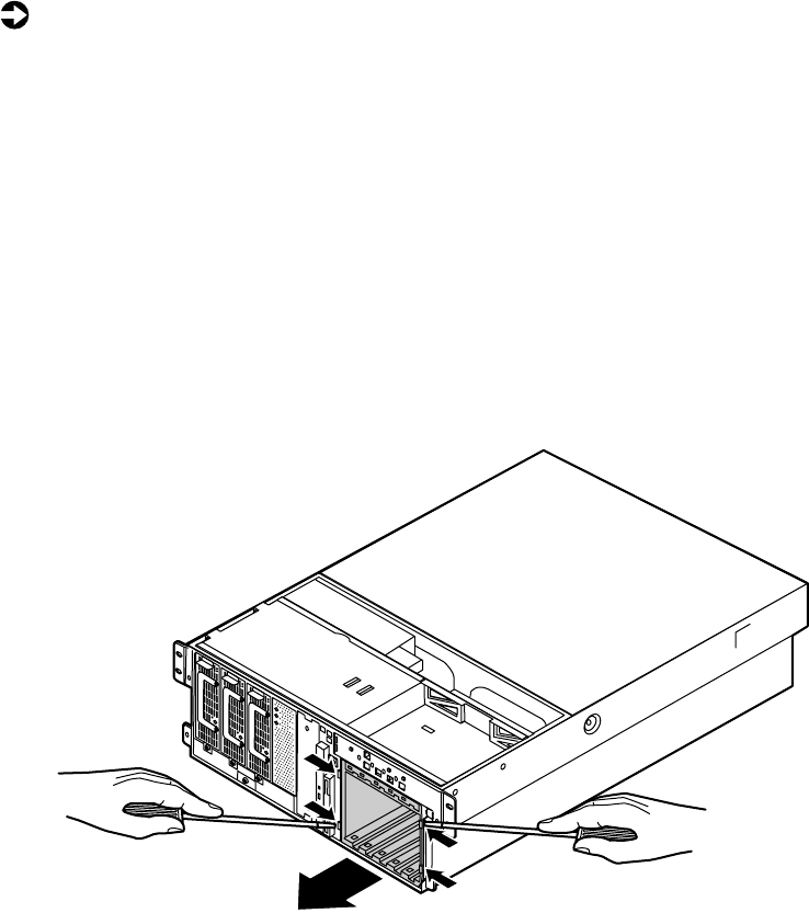
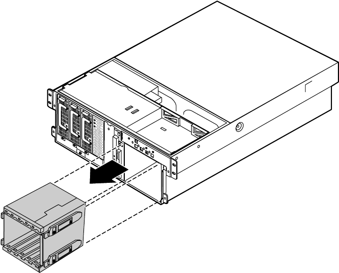
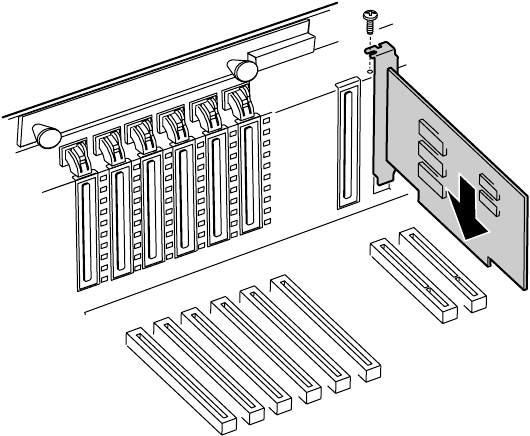
Replacing a hot-swap PCI card
You do not need to turn off the server to install or replace a hot-swap
expansion card.
To replace a hot-swap expansion card:
1Set any jumpers and switches on the replacement card, if required in the
card instructions.
8506284.book Page 73 Thursday, July 13, 2000 11:43 AM
74 Replacing and Adding Internal Devices
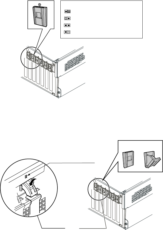
2On the back panel, check the hot-swap status indicator for the card you
are replacing or the slot you are filling. If the slot has power, (the first
LED is green) disable the card through software before replacing it.
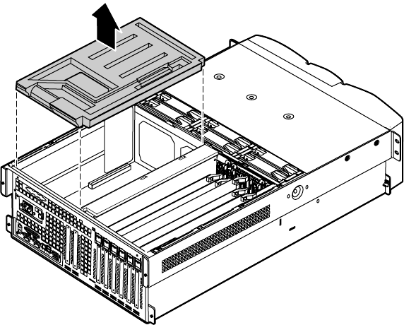
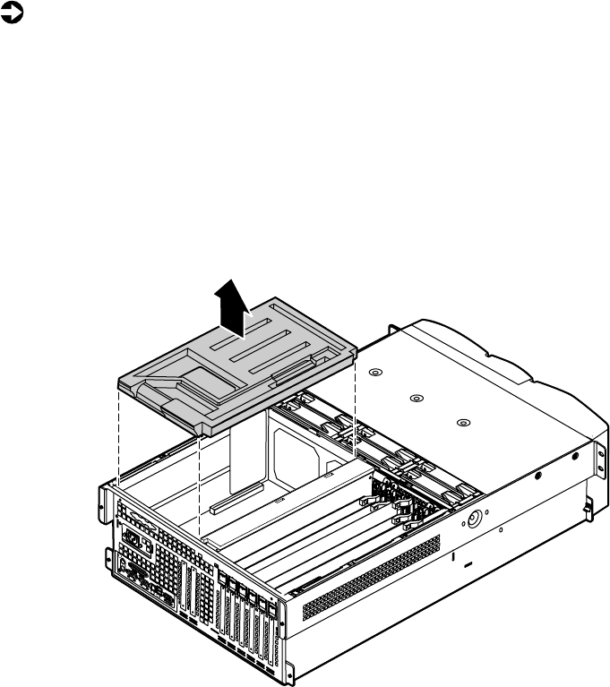
3Remove the back top panel according to the instructions in “Removing
the back top panel” on page 28.
4Open the hot-swap expansion card retention clip, by pressing gently on
the clip and rotating it through the back panel.
GREEN = Power to slot
AMBER = Fault on slot
Both Lights = Power to slot and Fault condition
Blinking GREEN = Power Up or Down Cycle
Hot-plug Status LEDs
Green and Amber LED’s
Press here
then rotate
Inside View Outside View
Closed
position Open
position
8506284.book Page 74 Thursday, July 13, 2000 11:43 AM
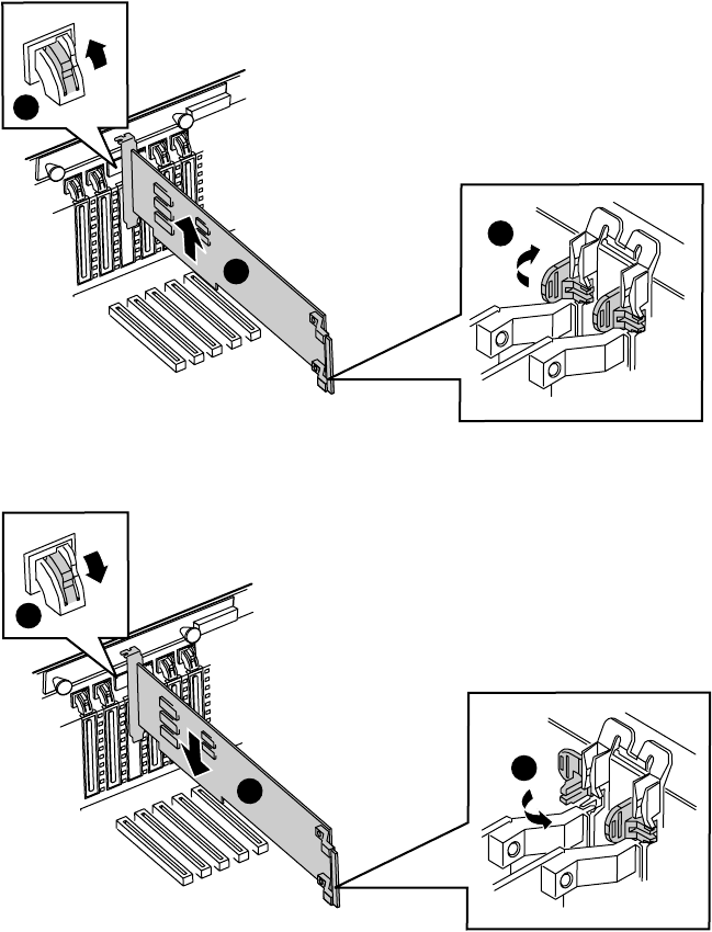
Expansion cards 75
5If the card is full-length, release the card retention mechanism at the end
of the card and pull the card from the slot.
6Insert the replacement card in the slot. Make sure it is fully seated.
7Push the hot-swap expansion card retention clip back through the back
panel until it clicks into place.
1
3
2
2
1
3
8506284.book Page 75 Thursday, July 13, 2000 11:43 AM

76 Replacing and Adding Internal Devices
8Close the card retention mechanism at the end of the card, if the card
is full length.
9Connect any cables to the card (see card documentation for proper cable
orientation).
10 Close the case. (See “Closing the case” on page 31.)
11 Reconnect the peripherals and the power cord, then turn on the server.
You may need to reconfigure the server after replacing a hot-swap expansion
card. You may also need to install upgrade software that came with the card.
Check the card documentation for additional information.
Replacing an expansion card
The server supports as many as two 32-bit, 33 MHz PCI expansion cards. These
cards are not hot-swap cards and you must turn off the server before replacing
one.
To replace an expansion card:
1Set any jumpers and switches on the replacement card, if required in the
card instructions.
2Turn off the server, then disconnect the power cord and all external
peripheral devices.
3Remove the back top panel according to the instructions in “Removing
the back top panel” on page 28. (See “Preventing static electricity
discharge” on page 25.)
8506284.book Page 76 Thursday, July 13, 2000 11:43 AM
Expansion cards 77
4Remove the EMI foam cover over the processors.
5Disconnect any cables attached to the card.
8506284.book Page 77 Thursday, July 13, 2000 11:43 AM

Expansion cards 79
8Connect any cables to the card (see card documentation for proper cable
orientation).
9Replace the EMI foam in the same orientation it was in when you
removed it.
10 Close the case. (See “Closing the case” on page 31.)
11 Reconnect the peripherals and the power cord, then turn on the server.
You may need to reconfigure the server after replacing an expansion card. You
may also need to install upgrade software that came with the card. Check the
card documentation for additional information.
8506284.book Page 79 Thursday, July 13, 2000 11:43 AM
80 Replacing and Adding Internal Devices
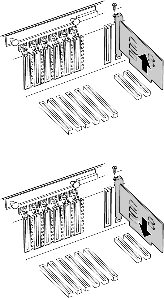
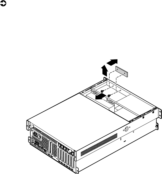
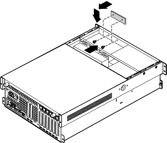
Adding an expansion card
The server supports as many as two 32-bit, 33 MHz PCI expansion cards. These
cards are not hot-swap cards and you must turn off the server before installing
one.
To install an expansion card:
1Set any jumpers and switches on the replacement card, if required in the
card instructions.
2Turn off the server, then disconnect the power cord and all external
peripheral devices.
3Remove the back top panel according to the instructions in “Removing
the back top panel” on page 28. (See “Preventing static electricity
discharge” on page 25.)
4Remove the EMI foam cover over the processors.
8506284.book Page 80 Thursday, July 13, 2000 11:43 AM
Expansion cards 81
5Locate an available slot and remove the slot cover by removing the screw
that secures it in place, then pull out the slot cover.
6Insert the bottom edge of the expansion card (the keyed edge with the
contacts) into the slot on the system board and push in firmly to seat
the card.
7Replace the screw you removed earlier.
8Connect any cables to the card (see card documentation for proper cable
orientation).
8506284.book Page 81 Thursday, July 13, 2000 11:43 AM

82 Replacing and Adding Internal Devices
9Replace the EMI foam in the same orientation it was in when you
removed it.
10 Close the case. (See “Closing the case” on page 31.)
11 Reconnect the peripherals and the power cord, then turn on the server.
You may need to reconfigure the server after installing some expansion cards.
You may also need to install software that came with the card. Check the card
documentation for additional information.
Power supplies
The server ships with as many as three 350-W hot-swap power supply
modules. With all three modules, the server provides N+1 power supply
redundancy, letting you hot-swap a power supply module if one fails. If the
power distribution system fails you must replace the entire power supply.
8506284.book Page 82 Thursday, July 13, 2000 11:43 AM
Power supplies 83
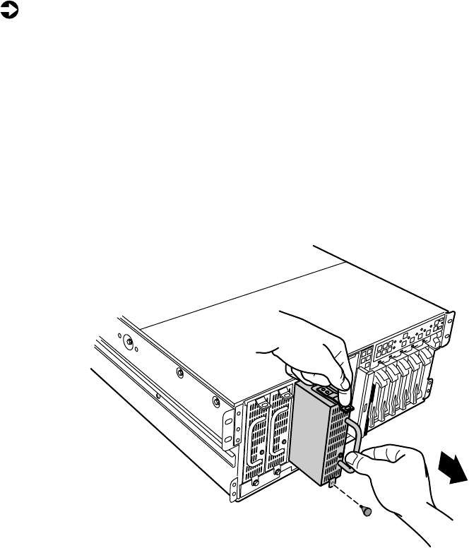
Hot-swapping a power supply module
If all three hot-swap power supply modules are installed, you can replace a
failed module without turning the server off.
To replace a hot-swap power supply module:
1Follow the static electricity precautions in “Preventing static electricity
discharge” on page 25.
2Determine which power supply has failed by checking the indicator LEDs
or using your server management software.
3Remove the bezel. (See “Removing the bezel” on page 27.)
4Loosen the captive thumbscrew at the bottom of the failed power supply
module.
5Press down on the tab at the top of the failed module and pull the module
out.
6Pull the power supply module entirely out of the chassis.
8506284.book Page 83 Thursday, July 13, 2000 11:43 AM

84 Replacing and Adding Internal Devices
7Align the rails on the new power supply module with the grooves at the
top and bottom of the power supply and slide the power supply module
in.
8Slide the module all of the way into the space until the clip at the top
clicks into place, then tighten the thumbscrew at the bottom of the power
supply module.
9Replace the bezel.
Replacing the power supply
The redundant 350-W power supply provides all system power. If one of the
components of the power distribution hardware fails, you must replace the
entire power supply.
To replace the power supply:
1Turn off the server and disconnect the power cord and all peripherals.
2Remove the bezel and the front top panel. (See “Removing the bezel”
on page 27, “Removing the front top panel” on page 29, and “Preventing
static electricity discharge” on page 25.)
8506284.book Page 84 Thursday, July 13, 2000 11:43 AM
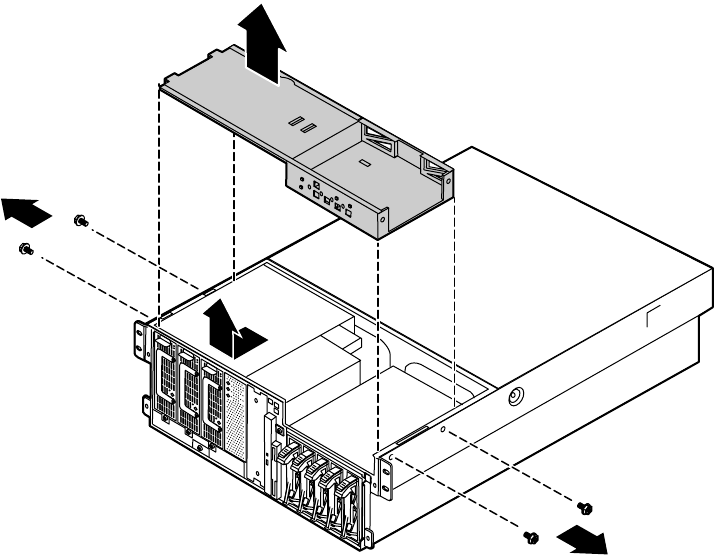
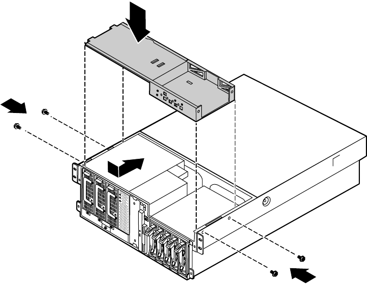
Power supplies 85
3Remove the four screws that secure the upper drive bay bracket in place,
then slide the bracket forward before lifting it from the chassis.
4Disconnect all cables attached to the power supply. Note their locations
and orientations so you can reconnect them later.
8506284.book Page 85 Thursday, July 13, 2000 11:43 AM
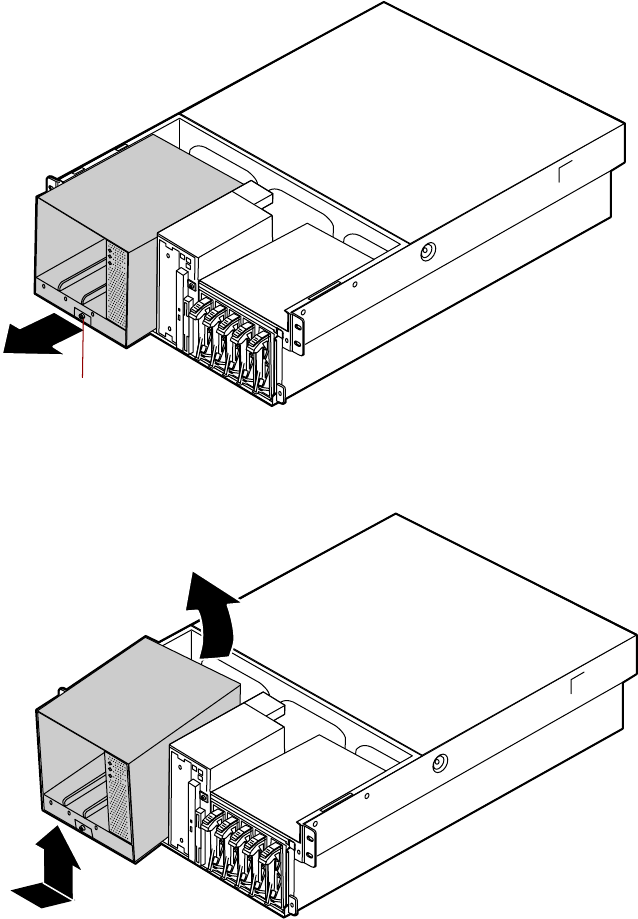
86 Replacing and Adding Internal Devices
5Loosen the captive thumbscrew at the bottom, center of the power supply
front, then slide the power supply forward until it stops.
6Tilt the power supply forward and lift it up and back to clear the tab on
the bottom of the chassis.
Captive thumbscrew
8506284.book Page 86 Thursday, July 13, 2000 11:43 AM
Power supplies 87
7Holding the new power supply at an angle, place the new power supply
over the tab on the bottom of the chassis, then rotate it so that it rests
flat on the bottom of the chassis.
8Slide the power supply back to insert the tabs on the back of the power
supply under the slots on the bottom of the chassis.
Captive thumbscrew
8506284.book Page 87 Thursday, July 13, 2000 11:43 AM
88 Replacing and Adding Internal Devices
9Tighten the thumbscrew at the bottom of the power supply to secure it
in place.
10 Place the upper drive bay bracket on the top of the chassis. Make sure
the tabs on the bottom of the bracket fit into the slots at either side of
the chassis.
11 Slide the upper drive bay bracket back to set the tabs, then replace the
four screws you removed in Step 3.
12 Close the case. (See “Closing the case” on page 31.)
13 Reconnect the power cord and all external peripherals, then turn on the
server.
8506284.book Page 88 Thursday, July 13, 2000 11:43 AM
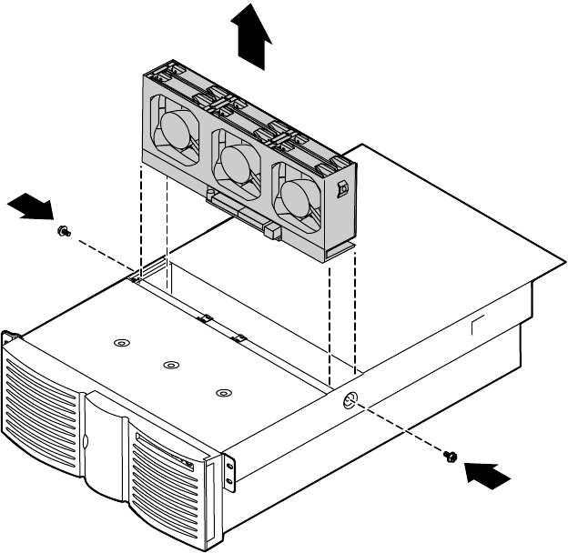
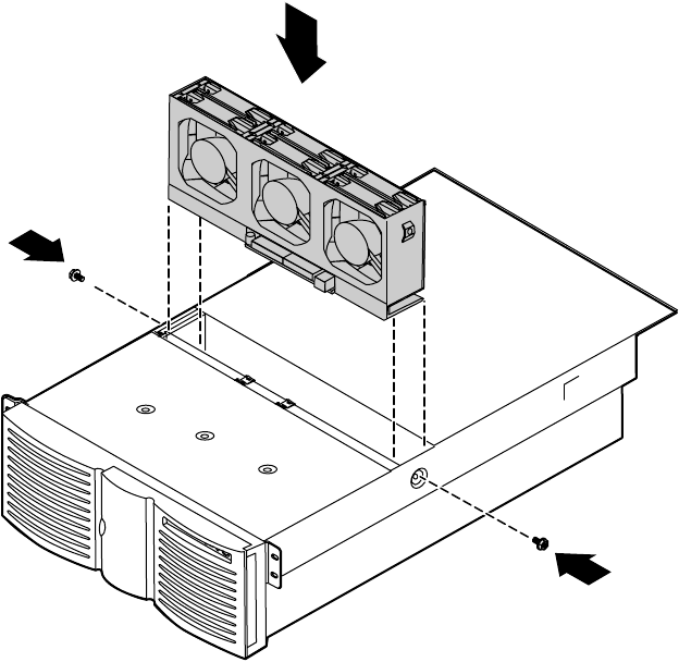
Fans 89
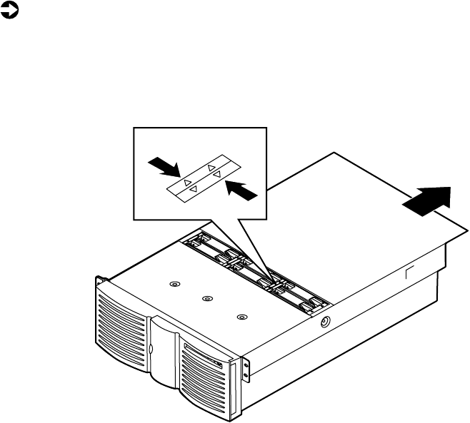
Fans
The server contains six hot-pluggable fans to keep the internal temperature
down to acceptable levels.
Replacing the fans
The fans are located between the electronics bay and the drive bays. The fans
are hot-plug capable so you do not need shut down the server to replace a fan.
To replace a fan:
1Remove the back top panel. (See “Removing the back top panel” on
page 28 and “Preventing static electricity discharge” on page 25.)
2Determine which fan has failed by looking at the fan status LEDs in the
fan tray.
8506284.book Page 89 Thursday, July 13, 2000 11:43 AM
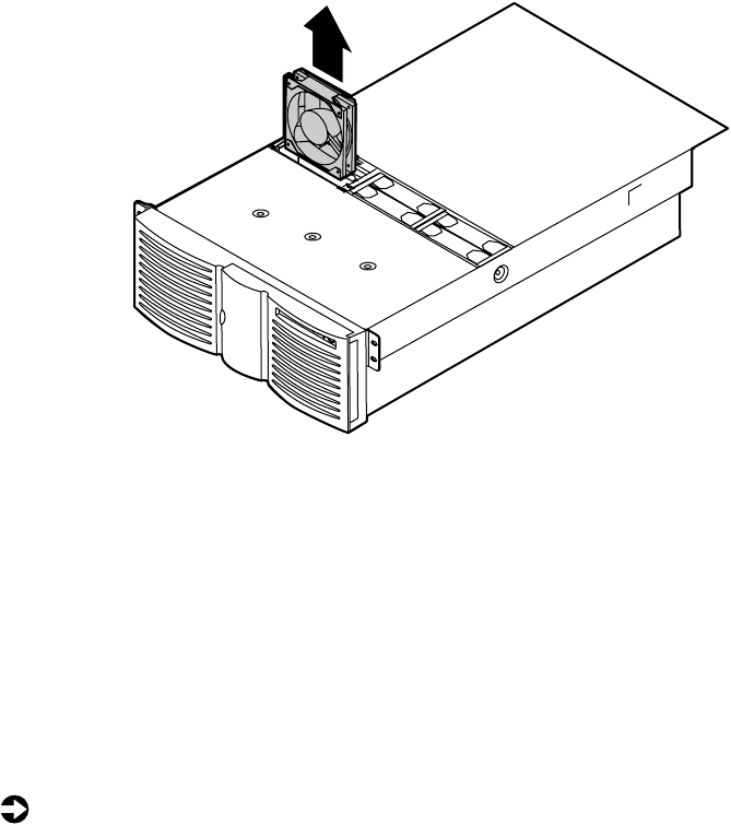
90 Replacing and Adding Internal Devices
3Place your fingers in the holes on the top of the fan and pull the fan
out of the fan tray. Wait until the fan blades stop rotating before you
put the fan down.
4Insert the new fan into the fan assembly. Make sure the direction of
rotation and airflow match the direction and airflow of the fan you
removed.
5Close the case. (See “Closing the case” on page 31.)
Replacing the fan power distribution board
The fan power distribution board rests in the bottom of the fan tray and
distributes power to all of the fans and the fan status LEDs. The fan power
distribution board also provides hardware monitoring for all fans.
To replace the power supply:
1Turn off the server and disconnect the power cord and all peripherals.
2Remove both top panels. (See “Opening the case” on page 26 and
“Preventing static electricity discharge” on page 25.)
3Remove all of the fans from the fan tray.
8506284.book Page 90 Thursday, July 13, 2000 11:43 AM
Fans 91
4Disconnect the cables from the bottom front side of the fan tray. Note
the location and orientation of each cable so you can connect them
correctly to the new board.
5Remove the two screws that secure the hot-plug fan tray, then lift the
tray out of the chassis and place it on a static-free surface.
8506284.book Page 91 Thursday, July 13, 2000 11:43 AM
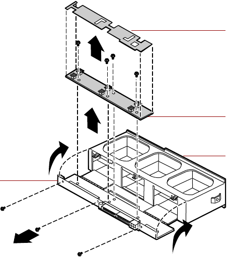
92 Replacing and Adding Internal Devices
6Remove the three screws at the bottom of the fan tray, then rotate the
top of the fan tray back on its hinges to expose the fan power distribution
board.
7Lift off the plastic board shield, then remove the four screws that secure
the fan power distribution board to the bottom of the fan tray and lift
the board out of the tray.
Plastic board
shield
Fan power
distribution board
Top of fan tray
Fan tray
8506284.book Page 92 Thursday, July 13, 2000 11:43 AM
Fans 93
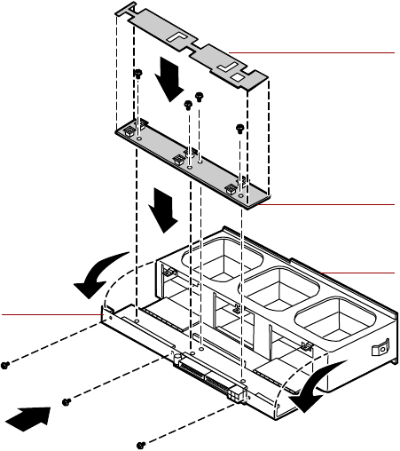
8Place the new fan power distribution board in the fan tray and secure it
with the four screws you removed in Step 7.
9Place the plastic board shield over the fan power distribution board, then
close the fan tray and secure it with the three screws you removed in
Step 6.
Plastic board
shield
Fan power
distribution board
Top of fan tray
Fan tray
8506284.book Page 93 Thursday, July 13, 2000 11:43 AM
94 Replacing and Adding Internal Devices
10 Place the fan tray in the chassis and secure it with the screws you removed
in Step 5.
11 Reconnect the cables you removed in Step 4.
12 Replace all of the fans in the fan tray.
13 Close the case. (See “Closing the case” on page 31.)
14 Reconnect the power cord and all external peripherals, then turn on the
server.
8506284.book Page 94 Thursday, July 13, 2000 11:43 AM
Replacing the front panel board 95
Replacing the front panel board
The front panel board is mounted on the front of the chassis, inside the front
panel.
To replace the front panel board:
1Turn off the server and disconnect the power cord and all external
peripherals.
2Remove the front top panel. (See “Removing the front top panel” on
page 29 and “Preventing static electricity discharge” on page 25.)
3Remove the two screws that secure the front panel board to the front of
the chassis, then remove the board from the server.
4Disconnect the cable from the front panel board. Note the location and
orientation of the cable as you remove it.
5Plug the front panel cable into the connector on the new front panel
board.
8506284.book Page 95 Thursday, July 13, 2000 11:43 AM
96 Replacing and Adding Internal Devices
6Install the new front panel board by placing the board in position and
replacing the two screws you removed in Step 4.
7Close the case. (See “Closing the case” on page 31.)
8Reconnect the power cord and the external peripherals, then turn on the
server.
8506284.book Page 96 Thursday, July 13, 2000 11:43 AM
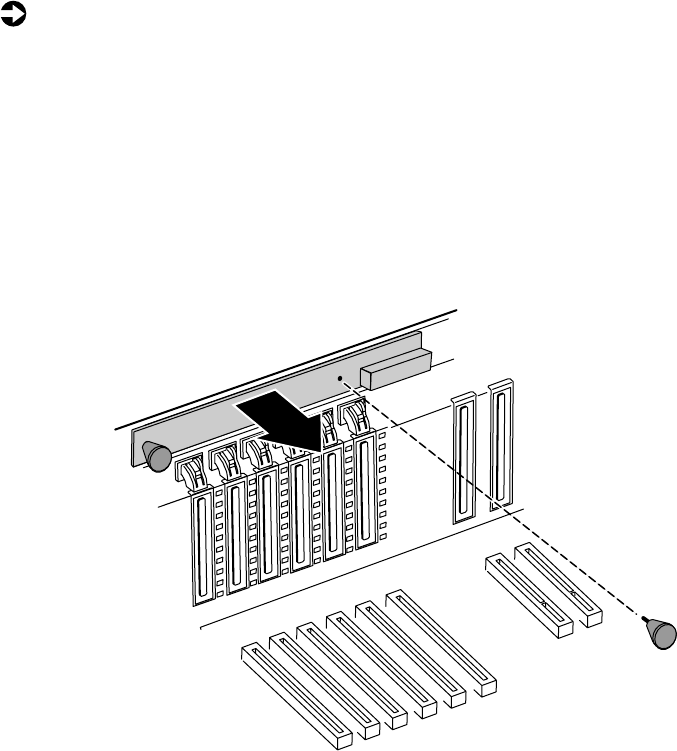
Replacing the hot-plug PCI indicator board 97
Replacing the hot-plug PCI indicator
board
The hot-plug PCI indicator board is mounted on the back panel of the chassis,
above the hot-plug PCI slots.
To replace the hot-plug PCI indicator board:
1Turn off the server and disconnect the power cord and all external
peripherals.
2Remove the back top panel. (See “Removing the back top panel” on
page 28 and “Preventing static electricity discharge” on page 25.)
3Disconnect the cable from the hot-plug PCI indicator board. Note the
location and orientation of the cable as you remove it.
4Remove the two thumbscrews that secure the board to the back panel,
then remove the board from the server.
8506284.book Page 97 Thursday, July 13, 2000 11:43 AM
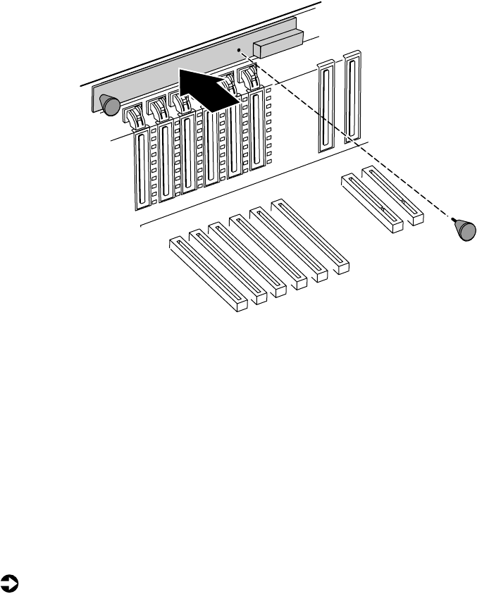
98 Replacing and Adding Internal Devices
5Install the new front panel board by placing the board in position and
replacing the two screws you removed in Step 4.
6Plug the hot-plug PCI indicator board cable into the connector on the
new board.
7Close the case. (See “Closing the case” on page 31.)
8Reconnect the power cord and the external peripherals, then turn on the
server.
Replacing the system board
The system board integrates the other elements of the server, such as the
processor, memory, storage, networking, and communications.
To replace the system board:
1Turn off the server and disconnect the power cord and all external
peripheral devices.
2Open the case. (See “Opening the case” on page 26 and “Preventing static
electricity discharge” on page 25.)
8506284.book Page 98 Thursday, July 13, 2000 11:43 AM
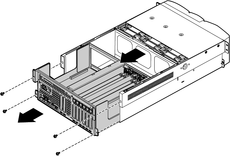
Replacing the system board 99
3Remove all expansion cards from the server. (See “Replacing a hot-swap
PCI card” on page 73 and “Replacing an expansion card” on page 76.)
4Disconnect all cables from the system board. Note the location and
orientation of each cable as you remove it.
5Remove the four screws that secure the electronics bay to the chassis, then
pull the electronics bay out through the back panel of the chassis and
place it on a static-free surface.
8506284.book Page 99 Thursday, July 13, 2000 11:43 AM

100 Replacing and Adding Internal Devices
6Remove the memory board retention bracket by removing the screw at
the back end, sliding the bar forward, and lifting the bracket out of the
slot.
8506284.book Page 100 Thursday, July 13, 2000 11:43 AM
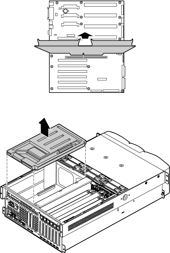
Replacing the system board 101
7Pull the memory board out of the chassis and put it on a static-free
surface.
8Remove the EMI foam cover over the processors.
Boards shown outside
chassis for clarity
8506284.book Page 101 Thursday, July 13, 2000 11:43 AM
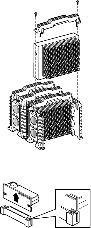
102 Replacing and Adding Internal Devices
9Remove the processors by removing the screws and the retention bracket.
10 Remove all of the VRMs from the system board by pulling the clips back
and pulling the VRM out of the socket.
8506284.book Page 102 Thursday, July 13, 2000 11:43 AM
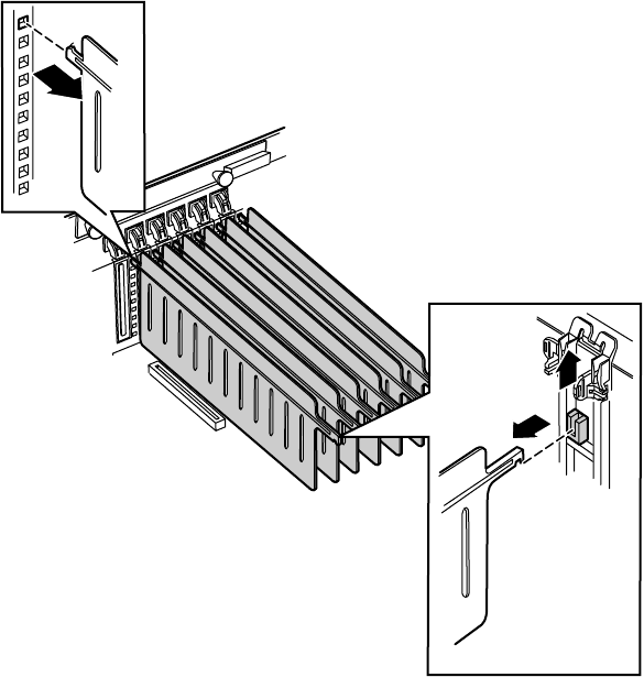
Replacing the system board 103
11 Remove the plastic hot-plug PCI curtains from the electronics bay by
pulling them out of the supports at each end.
8506284.book Page 103 Thursday, July 13, 2000 11:43 AM
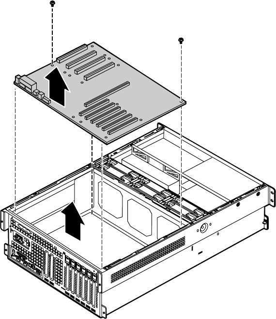
104 Replacing and Adding Internal Devices
12 Lift out the plastic system board shield, then remove the two screws and
pull out the system board.
13 Remove the new system board from its anti-static bag and set any jumpers
that you may need to set for your configuration. See “System board” on
page 13 and “Setting the system board jumpers” on page 114.
8506284.book Page 104 Thursday, July 13, 2000 11:43 AM

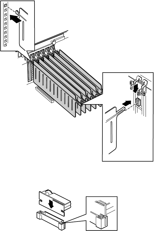
106 Replacing and Adding Internal Devices
15 Replace the plastic system board shield, then replace the plastic hot-plug
PCI curtains in the electronics bay.
16 Replace all of the VRMs in the system board. Press each one firmly into
the socket until the clips snap into place.
8506284.book Page 106 Thursday, July 13, 2000 11:43 AM

Replacing the system board 107
17 Replace all of the processors in the system board and secure them with
the retention brackets and two screws each.
8506284.book Page 107 Thursday, July 13, 2000 11:43 AM

108 Replacing and Adding Internal Devices
18 Replace the EMI foam cover over the processors.
8506284.book Page 108 Thursday, July 13, 2000 11:43 AM


110 Replacing and Adding Internal Devices
20 Slide the electronics bay back into the chassis and secure it in place with
the four screws you removed in Step 5.
21 Reconnect the system cables to the appropriate connectors on the system
board. See “System board” on page 13 for reference.
22 Replace the expansion cards and connect any required cables to the
expansion cards.
23 Close the case. (See “Closing the case” on page 31.)
24 Reconnect all peripherals and the power cord, then turn on the server.
25 Open the BIOS setup utility and correct any inaccurate settings. (See
“About the BIOS Setup utility” on page 111 for more information.)
8506284.book Page 110 Thursday, July 13, 2000 11:43 AM

About the BIOS Setup utility 111
5
Using the BIOS
Setup Utility
About the BIOS Setup utility
The server BIOS has a built-in setup utility that lets you configure several basic
system characteristics. The settings are stored in battery-backed RAM and are
retained even when the power is off.
Enter the BIOS Setup utility by restarting the server, then pressing F2 when
prompted during the startup process. The Main BIOS Setup utility screen
opens. It may not look exactly like the screen shown below.
BIOS Setup Utility
Main Advanced Security Server Boot Exit
Item Specific Help
System Time:
System Date:
Legacy Diskette A:
Legacy Diskette B:
Hard Disk Pre-Delay:
Primary IDE Master:
Primary IDE Slave:
Secondary IDE Master:
Secondary IDE Slave:
Processor Settings:
Language:
[xx:xx:xx]
[xx/xx/xxxx]
[ ]
[ ]
[enabled]
[auto]
[ ]
[ ]
[ ]
[English (US)]
F1 Help ↑↓ Select Item -/+ Change Values F9 Setup Defaults
ESC Exit ←→ Select Menu ENTER Select > Sub-Menu F10 Save & Exit
8506284.book Page 111 Thursday, July 13, 2000 11:43 AM
112 Using the BIOS Setup Utility
As you select items on the Main menu or in submenus, you see specific
information related to the current selection in the Item Specific Help box.
The command bar shows the keystrokes necessary to access help, navigate
through the menus, and perform other functions.
■F1 opens the Help screen, providing general help for using the BIOS Setup
utility.
■The ↑ (up arrow) and ↓ (down arrow) keys select items in the menu.
■The ← (left arrow) and → (right arrow) keys move you between the
menus.
■ENTER either moves you to a submenu screen when a selected item is
preceded by > or activates a selected field.
■ESC closes the screen you are in and returns you to the previous screen
or exits you from the BIOS Setup utility.
■F9 opens a screen that lets you return all values to their default settings.
■F10 opens a screen that lets you save all settings, then exit the BIOS Setup
utility.
The main screen has the following menu selections at the top of the screen:
■Main gives you access to basic information and settings related to your
system hardware and configuration.
■Advanced gives you access to information and settings for system
resources, hardware, and system configuration.
■Security gives you access to settings related to system access passwords.
■Server gives you access to information and options for server
management features.
■Boot gives you access to information and settings for boot features and
boot sequences.
■Exit gives you access to options for exiting the BIOS Setup utility.
Refer to the Help box on the right side of the BIOS Setup screens for
information about menu items.
8506284.book Page 112 Thursday, July 13, 2000 11:43 AM

Updating the BIOS 113
Updating the BIOS
If you need a new version of the BIOS, you can download the BIOS update
from the technical support area on the Gateway Web site
(www.gatewayatwork.com) and install the new version from a diskette.
To update the BIOS you need to perform the following tasks in sequence:
■Create a bootable diskette
■Note the current BIOS settings
■Create the BIOS update diskette
■Update the BIOS
■Restore the BIOS settings
Follow the detailed instructions for updating the BIOS that are included in
the self-extracting file that you can download from the technical support area
of Gateway’s Web site.
Important Whenever the BIOS is updated, the microcode table is
returned to the default setting. To update the table to the
proper settings for your processor, you must run the
MULOADER.EXE program, which is available from the
same site where you obtain the BIOS update files.
8506284.book Page 113 Thursday, July 13, 2000 11:43 AM
114 Using the BIOS Setup Utility
Setting the system board jumpers
The system board has three jumpers. Each of these jumpers has a specific
function described in the sections below.
The CMOS Clear jumper
The CMOS (complimentary metal-oxide semiconductor) Clear jumper on the
system board (pins 1 through 3 of jumper J9F2) lets you clear all BIOS Setup
settings, protect them, or place them under control of the BMC. (See the figure
on page 13 for the location of the jumper.)
The following table shows the settings required to perform those tasks. Make
sure you turn off the server and unplug the power cord before moving the
jumper.
Mode Jumper
Setting Action When Set
CMOS protected
Pins 1-2
Normal operation
Clear CMOS
Pins 2-3
Causes the server to clear all
BIOS settings and return to
defaults
Caution Moving the jumper while the power is on can damage your
server. Always turn off the server and unplug the power
cord(s) from the server before changing the jumper.
8506284.book Page 114 Thursday, July 13, 2000 11:43 AM

Setting the system board jumpers 115
Password Clear jumper
The Password Clear jumper on the system board (pins 5 through 7 of jumper
J9F2) lets you delete the passwords. (See the figure on page 13 for the location
of the jumper.)
The following table shows the settings required to perform this task. Make
sure you turn off the server and unplug the power cord before moving the
jumper.
Mode Jumper
Setting Action When Set
Protect
Pins 5-6
Normal operation
Clear
Pins 6-7
Clears all passwords at bootup
Caution Moving the jumper while the power is on can damage your
server. Always turn off the server and unplug the power
cord(s) from the server before changing the jumper.
8506284.book Page 115 Thursday, July 13, 2000 11:43 AM
116 Using the BIOS Setup Utility
BOOT Option jumper
The BOOT Option jumper on the system board (pins 9 through 11 of
jumper J9F2) lets you recover the BIOS. (See the figure on page 13 for the
location of the jumper.)
The following table shows the settings required to perform those tasks. Make
sure you turn off the server and unplug the power cord before moving the
jumper.
BIOS recovery mode
If you are trying to update the BIOS and have a problem such as a power
outage, the update may not be successful. You can then try to recover the
BIOS by setting the Boot Option jumper.
When you are trying to recover the BIOS, no image appears on your monitor.
To recover the BIOS:
1Turn off the server and disconnect the power cord, modem cord (if
installed), and all external peripheral devices.
2Remove the back top panel. (See “Removing the back top panel” on
page 28 and “Preventing static electricity discharge” on page 25.)
3Remove the jumper from pins 9-10 of jumper J9F2 (see “System board”
on page 13 for location) and place it on pins 10-11.
Mode Jumper
Setting Action When Set
Normal
Pins 9-10
Normal operation
Recovery
Pins 10-11
Causes the server to attempt
BIOS update or recovery from
diskette
Caution Moving the jumper while the power is on can damage your
server. Always turn off the server and unplug the power
cord(s) from the server before changing the jumper.
8506284.book Page 116 Thursday, July 13, 2000 11:43 AM
Setting the system board jumpers 117
4Close the case by following the instructions on page 31, then reconnect
the power cord.
5Place the bootable diskette containing the BIOS files into drive A:, then
turn on the server.
At the start of the BIOS recovery process, the server beeps once. The
recovery process may take a few minutes.
6When the process is completed, you will be prompted to remove the
diskette from drive A: and turn off the server.
7Disconnect the power cord and remove the back top panel again. (See
“Removing the back top panel” on page 28 and “Preventing static
electricity discharge” on page 25.)
8Place the jumper back on pins 9-10 of jumper J9F2.
9Close the case, reconnect the cords, then turn on the server.
10 Enter the BIOS Setup utility by pressing F2 when the Gateway Logo screen
appears.
11 Once in BIOS Setup utility, go to the appropriate tabs and select any BIOS
fields you want to change, then reenter the values you wrote down at
the beginning of this process.
12 Save your changes, then exit the BIOS Setup utility.
Troubleshooting: If the BIOS recovery was unsuccessful, go back to the
Gateway Web site and start the process over. If you continue to have problems,
contact Client Care or your system administrator.
8506284.book Page 117 Thursday, July 13, 2000 11:43 AM
118 Using the BIOS Setup Utility
8506284.book Page 118 Thursday, July 13, 2000 11:43 AM

Avoiding power source problems 119
6
Managing the
Server
Avoiding power source problems
Surge suppressors, line conditioners, and uninterruptible power supplies can
help protect the server against power source problems.
Surge suppressors
During a power surge, the voltage level of electricity coming into the server
can increase far above normal levels and cause data loss or system damage.
Protect your server and peripherals by connecting them to a surge suppressor,
which will absorb voltage surges and prevent them from reaching your server.
When purchasing a surge suppressor:
■Make sure the surge suppressor meets the appropriate product safety
certification for your location, such as Underwriters Laboratories (UL) or
Conformite European (CE).
■Check the maximum amount of voltage the suppressor allows to pass
through the line. The lower the voltage that the suppressor allows to pass
through, the better the protection for the server.
■Check the energy absorption (dissipation) rating. The higher the energy
absorption rating, the better the protection for the server.
■Check line-conditioner capabilities. A line conditioner smooths out some
normal line noise (small voltage fluctuations) of an electrical supply.
8506284.book Page 119 Thursday, July 13, 2000 11:43 AM

120 Managing the Server
Line conditioners
A line conditioner protects the server from the small fluctuations in voltage
from an electrical supply. Most systems can handle this variation (line noise)
without problems. However, some electrical sources include more line noise
than normal. Line noise can also be a problem if the server is located near,
or shares a circuit with, a device that causes electromagnetic interference, such
as a television or a motor.
Some surge suppressors and uninterruptible power supplies include simple
line-conditioning capabilities.
Uninterruptible power supplies
Use a standby uninterruptible power supply (UPS) to protect your server from
data loss during a total power failure. A UPS uses a battery to keep your server
running temporarily during a power failure and lets you save your work and
shut down your server. You cannot run your server for an extended period
of time while using only the UPS.
Maintaining and managing your hard
drive
Regular maintenance can keep your hard drive operating efficiently and good
file management can keep the server free of unwanted files while making
important files secure and easier to find.
Hard drive maintenance utility
If you are using the Windows NT operating system, you can help maintain
the performance of your hard drive by regularly using Check Disk.
Important For other operating systems, such as Windows 2000 or
Novell Netware, refer to the appropriate operating system
manual.
8506284.book Page 120 Thursday, July 13, 2000 11:43 AM

Maintaining and managing your hard drive 121
Using Check Disk in Windows NT
Bad sectors are parts of a hard drive or diskette that will not hold data. A lost
allocation unit is a group of sectors that has lost its place in the table that
the operating system uses to locate files. Check Disk checks the hard drive
for bad sectors or lost allocation units and lets you fix them.
Use Check Disk from once a week to once a month, depending on how often
you use the server. Also use Check Disk if you have any hard drive problems.
To use Check Disk:
1Double-click the My Computer icon. The My Computer window opens.
2Right-click the drive you want to check.
3Select Properties. The drive’s properties window opens.
4Click the Tools tab.
5At Error-checking, click Check Now. The Check Disk window opens.
6Scan the entire hard drive by selecting Scan for and attempt recovery of bad
sectors.
7Click Start. Check Disk checks the drive for errors.
8Follow any on-screen instructions for completing the scan.
Hard drive management practices
By deleting unneeded files from your hard drive and managing the space that
is automatically allocated for saving certain files, you can help maintain the
performance of the hard drive. We suggest that you first check your hard drive
for available space, then back up important files prior to deleting unneeded
files, in case you delete important files by mistake.
Checking hard drive space
In Windows, you can see a chart of the available hard drive space.
To check hard drive space:
1Double-click the My Computer icon on the desktop. The My Computer
window opens.
2Right-click the drive you want to check.
3Select Properties. The drive’s properties window opens. The General tab
shows you the available and used space on the drive.
8506284.book Page 121 Thursday, July 13, 2000 11:43 AM

122 Managing the Server
Backing up files
Regularly backing up your files protects you from losing data and lets you
keep fewer files on your hard drive. Back up old files to a large capacity disk
drive or tape drive and delete the files from your hard drive. You can use the
software that came with your tape backup drive or your large capacity disk
drive to back up the files.
You can also back up files by running the Backup utility that came with your
operating system. In Windows NT, Backup copies files to a tape drive.
To run Backup in Windows NT:
1Click Start, then select Programs, Administrative Tools, then Backup.
2Follow the on-screen instructions.
Deleting unneeded files
By deleting unneeded files from the hard drive, you free up space on the hard
drive and help improve hard-drive performance. The following sections give
you some simple ways to delete unneeded files.
Deleting Windows temporary files
During normal operation, Windows constantly creates new temporary (.tmp)
files. You can safely delete all but the most recent .tmp files.
To delete .tmp files:
1Open Windows Explorer, then select Tools, Find, then Files and Folders.
2In the Named text box, type *.tmp.
3In the Look in drop down list, select your drive letter.
4Click Find Now. The list of .tmp files appears.
5Click Modified above the list. To see the Modified button, you may need
to maximize the Find window. The list is sorted by date.
6Highlight all the files in the list except those with the current date.
7Press SHIFT + DELETE. A dialog box opens asking if you want to delete the
files.
8Click Yes. The files are deleted.
8506284.book Page 122 Thursday, July 13, 2000 11:43 AM

Maintaining and managing your hard drive 123
Deleting temporary Internet files
As you visit Web sites, your browser stores temporary Internet files on your
hard drive in a memory cache and a disk cache. Files in the memory cache are
removed when you turn off your server. Files are saved in the disk cache until
the space designated for the cache is full. See your browser’s Help files for
instructions on emptying the disk cache.
You can save space on the hard drive by decreasing the size of the Internet
disk cache. See your browser’s Help files for instructions.
Emptying the Recycle Bin
When you delete a file from your hard drive in Windows, it is not immediately
removed from the hard drive. Instead, the file is moved into the Recycle Bin.
Because files are stored in the Recycle Bin and not deleted from the hard drive
immediately, you can retrieve a file that you accidentally delete from the hard
drive.
To delete all the files from the Recycle Bin, right-click the Recycle Bin icon
on the desktop, then click Empty Recycle Bin.
You can save space on the hard drive by decreasing the size of the Recycle Bin.
To decrease the size of the Recycle Bin:
1Right-click the Recycle Bin, then select Properties.
2At the Global tab, select either Configure drives independently or Use one
setting for all drives.
3If you are configuring drives independently, click the tab for the drive
you want to configure.
4Move the slider to set the size of the Recycle Bin. A good initial setting
is 5%.
5Click OK.
8506284.book Page 123 Thursday, July 13, 2000 11:43 AM

124 Managing the Server
Protecting the server against viruses
A virus is a program that attaches itself to a program or data file on a computer,
then spreads from one computer to another. Viruses can damage data, cause
computers to malfunction, and can display annoying or offensive messages.
Some viruses can go unnoticed for long periods of time because they are
activated by a certain date or time. Protect your server from viruses by:
■Using an anti-virus program to check files and programs that are on
diskettes, attached to e-mail messages, or downloaded from the Internet.
After you run the anti-virus program you can back up your files to
diskettes, a separate hard drive, or a high-capacity storage drive.
■Keeping your anti-virus program updated.
■Obtaining all software from reputable sources and checking the software
for viruses before installing it.
■Disabling macros on suspicious Microsoft Word and Excel files. These
programs will warn you if a document that you are opening contains a
macro that might have a virus.
To remove a virus:
1Find and remove the virus immediately using an anti-virus program.
2Turn off your server and leave it off for at least 30 seconds.
3Turn on the server and rescan for the virus.
4If the virus is still present, contact the manufacturer of your anti-virus
program or Gateway Client Care.
8506284.book Page 124 Thursday, July 13, 2000 11:43 AM
System administration and control 125
System administration and control
The server has three server-management tools included to enable
administration and control of Windows NT environments. These tools are
Intel® Server Control (ISC), ManageX Event Manager, and the Direct Platform
Control (DPC) Console. Each tool provides some of the system security
features.
Intel Server Control (ISC)
Using a graphical user interface, ISC can locally or remotely provide real-time
monitoring and alerting for server hardware sensors. ISC monitors and records
system status indicators such as temperature, voltage, cooling, chassis
intrusion, processor status, cooling fan status, and power supply status. You
can establish a threshold or range of accepted values for each of these
indicators and you can configure ISC to respond to variances in a number of
ways, from an entry in the event log, to a displayed message or audio alarm,
or even a complete server shutdown.
ISC also provides a system hardware inventory, SCSI controller status, LAN
adapter status, and BIOS and system slot information.
You can find additional information about Intel Server Control under
Documentation on the Server Companion CD which came with the server.
ManageX Event Manager
ManageX lets the system administrator manage multiple systems on a
Windows NT, Windows 2000, or Novell Netware network from a single
window, and implement commands and policies across the network with a
single action. With this tool you can automate system management tasks,
which can be triggered by specific events or at specified thresholds.
You can find additional information about the ManageX Event Manager
under Documentation on the Server Companion CD which came with the
server.
8506284.book Page 125 Thursday, July 13, 2000 11:43 AM
126 Managing the Server
Direct Platform Control (DPC) Console
The Direct Platform Control (DPC) Console provides remote emergency
management of servers. The DPC Console is independent of the server
operating system and provides a means to remotely diagnose problems or
verify the state of the server. It will also turn the server on or off.
You can find additional information about DPC Console under Documentation
on the Server Companion CD which came with the server.
System security
To help prevent unauthorized entry or use of the system, the server includes
key locks on the chassis (to prevent entry) and the bezel door (to prevent use).
You can also set security measures in the BIOS Setup utility which establishes
passwords and automatic system lockouts. The system also includes server
management software that monitors the chassis intrusion switch.
Mechanical locks and monitoring
The server includes a chassis intrusion switch. When the access cover is
opened, the switch transmits an alarm signal to the system board, where server
management software processes the signal. You can program a response to
an intrusion, for example, the server may power down or lock the keyboard.
Software locks through the BIOS Setup utility
The BIOS Setup utility provides several security features to prevent
unauthorized or accidental access to the system. Once the security measures
are enabled, access to the system is allowed only after you enter the correct
password(s). For example, the utility lets you:
■Enable the keyboard lockout timer so the server requires a password to
reactivate the keyboard and mouse after a specified time-out period of 1
to 120 minutes
■Set and enable administrator and user passwords
■Set secure mode to prevent keyboard or mouse input and to prevent use
of the front panel reset and power switches
■Activate a hot-key combination to enter secure mode quickly
■Disable writing to the diskette drive when secure mode is set
8506284.book Page 126 Thursday, July 13, 2000 11:43 AM
System administration and control 127
Using passwords
If you set and enable a user password but not an administrator password, enter
the user password to boot the server with limited BIOS Setup access.
If you set and enable both a user and an administrator password:
■Enter either one to boot the server and enable the keyboard and mouse
■Enter the administrator password to gain full access to the BIOS Setup
to change the system configuration
Secure mode
Configure and enable the secure boot mode by using the BIOS Setup. When
secure mode is in effect, you:
■Can boot the server and run the OS, but you must enter the user password
to use the keyboard or mouse
■Cannot turn off server power or reset the system from the front panel
switches
Taking the system out of secure mode does not change the state of server
power. That is, if you press and release the power switch while secure mode
is in effect, the server will not power off when secure mode is later removed.
However, if the front panel power switch remains depressed when secure
mode is removed, the server will power off.
8506284.book Page 127 Thursday, July 13, 2000 11:43 AM

128 Managing the Server
Summary of software security features
The following table lists the software security features and describes what
protection each offers. In general, to enable or set the features listed here, you
must run the BIOS Setup utility and go to the Security Menu. The table also
refers to other Setup utility menus. For more information on setting the
security features, see “About the BIOS Setup utility” on page 111.
Feature Description
Secure boot mode To enter secure mode, set and enable a password to automatically
put the server into secure mode.
If you set a hot-key combination, you can secure the system by
pressing the key combination. This means you do not have to wait
for the inactivity time-out period.
When the system is in secure mode, the server boots and runs
the operating system. It does not accept mouse or keyboard input
until you enter the user password.
At bootup, if the server detects a CD in the CD drive or a diskette
in drive A, it requests a password. When you enter the password,
the server boots from CD or diskette and disables secure mode.
If you have not installed a CD drive or if there is no CD in the drive
or diskette in drive A, the server boots from drive C and
automatically enters secure mode. All enabled secure mode
features go into effect at bootup.
To leave secure mode, enter the correct password(s).
Disable writing to
diskette In secure mode, the server will not boot from or write to a diskette
unless a password is entered. To set these features, see “About
the BIOS Setup utility”on page 111.
Disable the power and
reset buttons If you enable this protection feature, the server disables the power
and reset buttons when in secure mode.
Set a time-out period
so that keyboard and
mouse input are not
accepted.
You can specify and enable an inactivity time-out period from 1 to
120 minutes. If no keyboard or mouse action occurs for the
specified period, keyboard and mouse input is not accepted. To
set this feature, see “About the BIOS Setup utility”on page 111.
Control access to the
BIOS Setup utility (set
administrator
password)
To control access to the system configuration, set an administrator
password and enable it through the BIOS Setup utility.
If both the administrator and user passwords are enabled, either
can be used to boot the server or enable the keyboard and/or
mouse, but only the administrator password allows changes to the
BIOS Setup utility.
Once set, passwords can be disabled by setting the password to
a null string or by changing the Clear Password jumper. See
“Password Clear jumper”on page 115.
8506284.book Page 128 Thursday, July 13, 2000 11:43 AM

System administration and control 129
Control access to the
system other than
BIOS Setup (set user
password)
To control access to the system, set a user password and enable
the Password on Boot option using the BIOS Setup utility.
Once set, passwords can be disabled by deleting the password
or by changing the Password Clear jumper. See “Password Clear
jumper”on page 115.
Boot without keyboard The server can boot with or without a keyboard. During POST and
before the server boots, the BIOS automatically detects and tests
the keyboard, if present, and displays a message. Do not plug in
a keyboard while the server is on.
Specify the boot
sequence The sequence you specify in the BIOS determines the boot order
(see “About the BIOS Setup utility”on page 111). If secure mode
is enabled (user password is set), you are prompted for a
password before the server boots fully. If secure mode is enabled
and the Secure Mode Boot option is also enabled, the server boots
fully but requires a password before accepting any keyboard or
mouse input.
Feature Description
8506284.book Page 129 Thursday, July 13, 2000 11:43 AM
130 Managing the Server
System recovery
Take precautions that allow you to recover damaged files and recover your
system in the event that your hard drive is damaged or your BIOS or system
files get corrupted.
Creating a startup diskette
If your server hard drive is damaged, you may not be able to start the server
from the hard drive. A startup diskette is a bootable diskette that lets you start
the server and attempt to fix the problem.
When you set up Windows NT, you are prompted to create a startup diskette.
If you did not choose to create a startup diskette at that time, you can create
one later by running the Windows NT upgrade/installation program. Perform
this process by going to the DOS Command Prompt, changing to the C:\I386
subdirectory and typing “winnt32/ox”. Press ENTER and follow the prompts.
Using your Server Companion CD
The Server Companion CD included with your server can be used to:
■Install hardware drivers for Windows NT
■Reinstall selected utilities
■Access system documentation
Instructions for each operating system are provided with the Server
Companion CD.
8506284.book Page 130 Thursday, July 13, 2000 11:43 AM

Introduction 131
7
Troubleshooting
Introduction
If the server does not operate correctly, re-read the instructions for the
procedures you have performed. If an error occurs within a program, refer to
the documentation supplied with the program. This section identifies
solutions to some possible problems.
Troubleshooting checklist
Before turning on the server, make sure that:
■The power cord is connected to the AC power-in connector and an AC
outlet.
■The AC outlet is supplying power.
■If a power strip is used, it is turned on.
■If the power supply has a voltage selection switch, the voltage selection
switch reflects the proper voltage.
Verifying your configuration
If the server is not operating correctly, the BIOS may contain an invalid
configuration parameter. Open the BIOS Setup utility and check your
configuration settings. (See “About the BIOS Setup utility” on page 111.)
8506284.book Page 131 Thursday, July 13, 2000 11:43 AM

132 Troubleshooting
Troubleshooting guidelines
As you troubleshoot the server, keep the following guidelines in mind:
■Never remove the chassis cover while the server is turned on.
■Do not attempt to open the monitor; it is extremely dangerous. Even if
the power is disconnected, stored energy in the components can be
dangerous.
■If a peripheral does not work, make sure that all connections are secure.
■If you see an error message on the screen, write it down, word for word.
You may be asked about it when calling Gateway Client Care.
■Only qualified personnel should open the server for maintenance.
■If you are qualified to maintain the server yourself, make sure you are
properly grounded before opening the server chassis. See Chapter 3, Case
Access, for more information on preventing electrostatic damage to the
server.
CD drive problems
The server does not recognize the CD drive
Probable cause Solution
The CD is not intended
for PC use Make sure that the disc is PC-compatible.
The CD is loaded
incorrectly Make sure that the label is facing up, then try again.
The CD is scratched or
dirty Try cleaning the CD with a lint-free cloth. Make sure the disk
is not scratched.
The CD drive needs to
be added as new
hardware
In the Control Panel window (Start |Settings |Control
Panel), double-click Add New Hardware. Follow the
on-screen instructions for adding the drive.
The secondary IDE
device may be disabled Restart your server, then press F2 to enter the BIOS Setup
utility program. From the Advanced | IDE
Configuration menu, set the IDE Controller to Both and
the Secondary IDE Master to Auto.
8506284.book Page 132 Thursday, July 13, 2000 11:43 AM

Diskette drive problems 133
Diskette drive problems
The system does not recognize the diskette drive
The diskette drive will not read, write, or format
The CD drive cables are
not installed correctly Open the server, then make sure all cables between the IDE
controller and the CD drive are correctly connected.
The CD drive may be
defective Replace the CD drive.
Probable cause Solution
Thediskettedrivemay
be configured incorrectly Restart your server, then press F2 to enter the BIOS Setup
utility. In the Boot | Removable Devices menu, make sure
that the diskette drive parameters are set correctly.
The drive cables are not
connected properly Open the server, then make sure all cables are properly
connected to the controller card. Some servers do not have
a floppy controller card because the floppy controller is built
into the system board.
The drive controller is not
seated properly Open the server, then reseat the drive controller. Some
servers do not have a floppy controller card because the
floppy controller is built into the system board.
Probable cause Solution
The diskette is not
IBM-formatted Make sure that the diskette you are trying to format is
IBM-compatible. If it is, try reformatting it. If not, get another
diskette.
The disk is
write-protected Make sure that the write-protection window on the
upper-right corner of the diskette is closed (unprotected).
The diskette is corrupted Run CheckDisk on the diskette. If errors are detected and
corrected, try accessing the diskette again.
Probable cause Solution
8506284.book Page 133 Thursday, July 13, 2000 11:43 AM

134 Troubleshooting
The diskette drive LED illuminates continuously
Hard drive problems
The server does not recognize a SCSI drive
Memory and processor problems
The system detected memory errors during start up
Probable cause Solution
The diskette is corrupted Remove the diskette from the drive. If the light remains on,
try restarting the server.
The cable to the drive is
not connected properly Open the server, then make sure the cable between the
diskette drive and its controller is properly connected. Make
sure that the pins are not bent or misaligned.
Probable cause Solution
SCSI hot-swap drive is
not seated correctly Open the server and reseat the hot-swap drive(s). This
problem is most common immediately after shipping.
The SCSI bus is not
properly terminated Open the server and make sure that the last device on the
SCSIbusisproperlyterminated.
The drive is configured
with a conflicting SCSI
address
Change the device’s SCSI address to one that is not
currently being used by the server.
The cables are not
connected correctly Open the server, then make sure the cables are connected
properly.
Probable cause Solution
Memory was added or
removed, and the new
configuration was not saved
in the BIOS Setup utility
Open the BIOS Setup utility and save the new memory
configuration.
The memory was installed
incorrectly Make sure that the memory is proper seated and
oriented.
8506284.book Page 134 Thursday, July 13, 2000 11:43 AM

Modem problems 135
The system does not recognize a new or second processor
Modem problems
The system does not recognize the modem
A memory chip is faulty Replace the card with the faulty chip. Third-party
diagnostic programs can help determine which chip or
memory segment is failing.
Probable cause Solution
The processor was installed
incorrectly Check the installation. Make sure that the processor
is fully seated in its socket. The processor should be
recognized automatically if it was installed correctly.
The processor speed was not
set correctly in the BIOS Setup
utility
If the server BIOS lets you select the processor
speed, make sure that you have selected the proper
speed.
The system only detected one
processor Enable the processor retest in the BIOS Setup utility.
Probable cause Solution
The modem has not been
added as new hardware Add the modem as new hardware.
The modem is not connected
toalivephonejack Make sure that the line connected to the modem is
working and plugged into the appropriate port on the
modem (line port).
The telephone line is in use If the modem shares the jack with another device, make
sure that the other device does not have the port open.
The modem is not configured
with a valid interrupt or
address
Check the system settings for possible conflicts. If one
exists, correct the problem by selecting an available
interrupt and address.
Probable cause Solution
8506284.book Page 135 Thursday, July 13, 2000 11:43 AM

136 Troubleshooting
Peripheral/Adapter problems
The system does not recognize a SCSI device
The system does not recognize an expansion card
Probable cause Solution
The device needs to be
added as new hardware From the Control Panel window (Start | Settings | Control
Panel), double-click Add New Hardware. Follow the
on-screen instructions for adding the device.
The SCSI ID may be
invalid Assign an available SCSI ID to the device.
The SCSI bus is not
terminated Make sure the last device on the SCSI bus is terminated.
The device cables are
not installed correctly Open the server, then check all cables between the controller
and the device.
Probable cause Solution
The interrupt or I/O
address is set incorrectly Check the address configuration of the adapter card and
make sure that it does not conflict with another card in the
server.
The card has not been
configured through the
software
Configure the card with the appropriate software.
The card was not installed
correctly Make sure the card jumpers are set correctly and reseat
the card.
8506284.book Page 136 Thursday, July 13, 2000 11:43 AM

Printer problems 137
Printer problems
The printer will not turn on
The printer is turned on but will not print
The printer prints garbled text
Probable cause Solution
The printer is not turned
on Make sure that the power switch is depressed or set to the
On position. If the printer is turned on, the green power LED
should be illuminated.
The printer is not
plugged in Make sure that the power cable is plugged into a live power
source.
The printer is defective Try another printer, if one is available.
Probable cause Solution
The printer is not online
(ready) Make sure the on-line or ready light is on, or the display
indicates “Ready.”
The printer is not connected
to the system Make sure the data cable between the printer and the
system is properly connected. Make sure that it is
connected to the proper port. Make sure the connector
and cable have no bent or broken pins.
The printer is not designated
as the default printer If the printer that you are trying to print to is not the
default printer, make sure that you have selected it
through the program printer setup function.
The printer has not been
added to the system In the Printers window (Start | Settings | Printers),
double-click Add Printer. Follow the on-screen
instructions for adding the new printer.
Probable cause Solution
The wrong driver is being
used for the selected
printer
In the Printers window (Start |Settings |Printers), select
the printer. From the File menu, click Properties. Make sure
that the printer is using the correct printer driver. If not, install
the correct one.
8506284.book Page 137 Thursday, July 13, 2000 11:43 AM

138 Troubleshooting
System problems
The system will not start up
The system is non-responsive
The keyboard does not work
Probable cause Solution
The system is not connected to
an AC outlet Make sure that the power cable is connected to an
operating AC power source.
Voltage selection switch not
set correctly Make sure that the voltage selection switch is set to
the correct power source.
A power supply module has
failed Power supply alarm buzzes and power supply status
LED blinks indicating a failed power supply module.
Replace the indicated power supply module. (You can
turn off the audible alarm by inserting an appropriate
tool into the port on the front panel and pressing the
switch.)
The power supply has failed The power supply alarm buzzes and all power supply
status LEDs blink, indicating a failed common
component.
Replace the entire power supply housing. (One or
more of the power supply modules may also be bad.)
Probable cause Solution
An error occurs during an
application or the server
may be out of memory
Restart your server by pressing the reset button. If the
system is still non-responsive, press and hold in the power
button for 4 seconds to turn the server off. Turn the server
back on, then follow the on-screen instructions.
Keyboard, mouse, and front
panel are locked out when
the password is set
Enter the password.
Probable cause Solution
Keyboard is locked out
when the password is set Enter the password.
8506284.book Page 138 Thursday, July 13, 2000 11:43 AM

System problems 139
The mouse does not work
The server power and reset buttons are not responsive:
A key was depressed while
the server was starting up Clearthestickingkey,thenturnofftheserver,waitfora
few seconds, then turn the server back on.
The keyboard is not plugged
in or connected properly Make sure the cable is properly connected.
Something spilled into the
keyboard Turn off the server. Turn the keyboard upside down to
drain it, then turn is right-side up to let it dry before using
the keyboard again.
The keyboard is defective Try a keyboard that you know is working.
Probable cause Solution
Mouse is locked out when the
password is set Enter the password.
The mouse is not plugged in
or connected properly Make sure that the cable is plugged in correctly.
The mouse driver did not load
when the server started Load the appropriate mouse driver manually or contact
technical support.
The mouse is defective Try a mouse that you know is working.
Probable cause Solution
The front panel is locked out
when the password is set Enter the password.
Probable cause Solution
8506284.book Page 139 Thursday, July 13, 2000 11:43 AM

140 Troubleshooting
Video problems
The system is running but the screen is blank
Probable cause Solution
The monitor is not turned on Make sure that the monitor is plugged in and turned on.
If the monitor is turned on, the green power LED should
illuminate.
The monitor data cable is
not connected Make sure that the monitor data cable is connected to the
video controller on the back of the server.
The connector or cable is
damaged Check the connector and cable for bent or damaged pins.
The monitor brightness and
contrast controls are turned
down
Adjust the brightness and contrast knobs to the center
position.
The monitor is defective Connect a working monitor to the server.
The video card is not seated
correctly Open the server, then make sure the video card is seated
properly. Some servers do not have a video controller
card because the video controller is built into the system
board.
The video card is not
compatible with the server Check the documentation or technical support to make
sure that the video card is compatible with the server. If
not, obtain a compatible video card. The server board
may have a built-in video adapter, so there may not be
a video adapter to remove and replace.
The terminator card or the
second processor is not
seated properly
Open the server and reseat the terminator card or the
second processor.
8506284.book Page 140 Thursday, July 13, 2000 11:43 AM

Video problems 141
The image on the screen is dim or difficult to read
The color monitor displays everything in black and white
The displayed characters are garbled
Probable cause Solution
The monitor brightness and
contrast controls are turned
down
Adjust the brightness and contrast knobs until the text
becomes clear.
Sunlight is glaring off the
display Position the monitor away from the sun or a window.
The monitor may be old Replace the monitor.
Probable cause Solution
The server was turned
on before the monitor Make sure that the monitor is turned on, then restart the
system.
The display type is set
incorrectly In the Control Panel window (Start |Settings |Control
Panel), double-click Display, set the display to the
appropriate monitor type, then restart the server.
Probable cause Solution
The video cable is damaged Make sure the connector and cable have no bent or
damaged pins.
The display setup is incorrect In the Control Panel window (Start |Settings |Control
Panel), double-click Display and check the settings.
The correct video type should be selected, along with
a supported resolution. Check your monitor and video
controller documentation for details.
The video card has failed Try another video card.
8506284.book Page 141 Thursday, July 13, 2000 11:43 AM

142 Troubleshooting
The video is distorted
Error messages
This section lists common error messages that you may see. These messages
often indicate procedural errors such as an incorrect keystroke or a
write-protected diskette. Some messages, however, may indicate a problem
that requires you to consult the troubleshooting section of this manual.
Probable cause Solution
The monitor controls are
not properly adjusted Adjust the monitor controls until the text becomes clear. (See
your monitor documentation for more information.)
The connector or cable is
damaged Check the connector and cable for bent or damaged pins.
The surge protector or
UPS is damaged Disconnect the monitor power cable, then connect it directly
to the power source.
The monitor is too close
toasourceofelectrical
interference
Move the monitor away from sources of electrical
interference, such as televisions, unshielded speakers,
microwave ovens, fluorescent lights, and metal beams or
shelves.
The monitor needs to be
degaussed Turn off the server and monitor and leave them off for at least
a half hour, then restart the server.
Error message Solutions
Access denied Try saving to a new file or diskette.
Move the write-protection tab over the hole on the back of
the diskette.
Bad command or file name Make certain you entered the right command.
Verify the specified drive, then try it again.
If you are trying to exit MS-DOS to return to Windows, type
exit, then press ENTER.
Base memory [xxx]
expansion This is an informational message only. No action is required.
Checking RAM on disk
controller Your BIOS configuration is incorrect. Open the BIOS Setup
utility, then make sure the settings are correct.
CD-ROM is not recognized See “The server does not recognize the CD drive”on
page 132 for a possible solution.
Data error Use CheckDisk on the drive with the error.
8506284.book Page 142 Thursday, July 13, 2000 11:43 AM

Error messages 143
Decreasing available
memory Your BIOS configuration is incorrect. Enter the BIOS Setup
utility, then make sure the settings are correct.
Diskette drive is not
recognized See “The system does not recognize the diskette drive”on
page 133 for a possible solution.
Diskette drive 0 seek to track
0failed Enter the BIOS Setup utility, then make sure the settings
are correct.
Check the diskette drive cables. Make sure that Pin 1 on
the cable aligns with Pin 1 on the connector.
Diskette drive reset failed Open the BIOS Setup utility, then make sure the settings
are correct.
Check the diskette drive cables. Make sure Pin 1 on the
cablealignswithPin1ontheconnector.
Diskette read failed - strike F1
to retry boot Make sure that the boot disk contains the Command.com
file.
Use the BIOS Setup utility (if necessary) to make sure that
your drive or controller configuration is correct.
Press F1 to try to restart the server.
Gate A20 failure You may have an XT keyboard connected to an AT system
or vice versa. Make sure that the keyboard is configured to
work with the appropriate system. Some keyboards have a
switch to select either AT or XT.
Hard disk controller failure Make sure that the hard drive cable is properly connected.
Open the BIOS Setup utility, then make sure that the correct
drive type is selected.
Hard disk controller failure -
press F1to try reboot The drive controller may be defective. Press F1 to try to
restart the server.
Try running a disk formatting utility. For more information,
refer to your operating system documentation.
Insert bootable media device See “The server does not recognize a SCSI drive”on
page 134 for a possible solution.
Backup your files as soon as possible.
Insufficient disk space Check the free space on the disk volume. If the volume is
full or almost full, remove unnecessary files.
Invalid configuration
information Open the BIOS Setup utility, then make sure the settings
are correct.
Error message Solutions
8506284.book Page 143 Thursday, July 13, 2000 11:43 AM

144 Troubleshooting
Invalid password Enter your password again, make sure to enter it correctly.
Be aware that some passwords are case sensitive.
Ifyoudonotknowthepassword,youmayneedtoreinstall
the software you are trying to access.
Startup passwords are stored in BIOS. If this password has
been set and is unknown, you may be able to reset the
password via system board jumper settings.
Keyboard clock line failure Try a working keyboard.
Make sure that the keyboard is compatible with the system.
You may have to change the switch setting to AT.
Keyboard controller failure Try a working keyboard.
Make sure that the keyboard is compatible with the system.
You may have to change the switch setting to AT.
Keyboard not detected See “The keyboard does not work”on page 138 for a
possible solution.
Turn off the server, then check the keyboard cable.
Keyboard stuck key failure Remove any objects that may be resting on the keyboard,
then restart the server.
Check for sticking keys. Clean the keyboard if necessary.
Memory errors were
detected while the server
powered up
See “The system detected memory errors during start up”
on page 134 for a possible solution.
Memory size error Enter the BIOS Setup utility and save the memory
configuration.
Non-system disk or disk error Eject the diskette, then press ENTER.
If the diskette is bootable, check it for errors.
Not enough memory Close all programs that are not currently in use.
Print queue is full Wait until the current print job has completed before sending
another print job.
If you receive this error often, you need to add memory to
the printer.
Printer is out of paper Add paper to the printer.
Make sure that the printer is online.
Required parameter missing Make sure that you entered the right command.
If you are trying to exit MS-DOS to return to Windows, type
exit,thenpressENTER.
Syntax error Make sure that you entered the right command.
If you are trying to exit MS-DOS to return to Windows, type
exit,thenpressENTER.
Error message Solutions
8506284.book Page 144 Thursday, July 13, 2000 11:43 AM

Error messages 145
Time and date not set Open the BIOS Setup utility, then set the system date and
time.
Write protect error Move the write-protection tab over the hole on the back of
the diskette.
Error message Solutions
8506284.book Page 145 Thursday, July 13, 2000 11:43 AM
146 Troubleshooting
8506284.book Page 146 Thursday, July 13, 2000 11:43 AM

Safety, Regulatory, and Notices 147
A
Safety,
Regulatory, and
Notices
The Gateway 8450R Server originally shipped with a Class A rating according
to FCC rules part 15. Later modifications may have improved the rating to
Class B. To check the rating of the server as shipped to you, check the FCC
label at the back of the chassis for the rating.
Important safety information
Your Gateway server is designed and tested to meet the latest standards for safety of information
technology equipment. However, to ensure safe use of this product, it is important that the safety
instructions marked on the product and in the documentation are followed.
Settingupyourserver
■Read and follow all instructions marked on the product and in the documentation before you
operate your server. Retain all safety and operating instructions for future use.
■Do not use this product near water or a heat source such as a radiator.
■Make sure you set up the server on a stable work surface.
■The product should only be operated from the type of power source indicated on the rating
label.
■If your server has a voltage selector switch, make sure that the switch is in the proper position
for your area. The voltage selector switch is set at the factory to the correct voltage.
Warning Always follow these instructions to help guard against
personal injury and damage to your Gateway server.
8506284.book Page 147 Thursday, July 13, 2000 11:43 AM

148 Safety, Regulatory, and Notices
■Openings in the server case are provided for ventilation. Do not block or cover these openings.
Make sure you provide adequate space, at least 6 inches (15 cm), around the server for
ventilation when you set up your work area. Never insert objects of any kind into the server
ventilation openings.
■Some products are equipped with a three-wire power cord to make sure that the product is
properly grounded when in use. The plug on this cord will only fit into a grounding-type outlet.
This is a safety feature. If you are unable to insert the plug into an outlet, contact an electrician
to install the appropriate outlet.
■If you use an extension cord with this server, make sure that the total ampere rating on the
products plugged into the extension cord does not exceed the extension cord ampere rating.
■If your server is fitted with a TV Tuner, cable, or satellite receiver card, make sure that the
antenna or cable system is electrically grounded to prevent against voltage surges and build
up of static charges.
Care during use
■Do not walk on the power cord or allow anything to rest on it.
■Do not spill anything on the server. The best way to avoid spills is to avoid eating and drinking
near your system.
■Some products have a replaceable CMOS battery on the system board. There is a danger of
explosion if the CMOS battery is replaced incorrectly. Replace the battery with the same or
equivalent type recommended by the manufacturer. Dispose of batteries according to the
manufacturer’s instructions.
■When the server is turned off, a small amount of electrical current still flows through the server.
Always unplug all power cables and modem cables from the wall outlets before cleaning the
server.
■Unplug the server from the wall outlet and refer servicing to qualified personnel if:
■The power cord or plug is damaged.
■Liquid has been spilled into the server.
■The server does not operate properly when the operating instructions are followed.
■The server was dropped or the cabinet is damaged.
■The system performance changes.
Replacement parts and accessories
Use only replacement parts and accessories recommended by Gateway.
Important Do not use Gateway products in areas classified as
hazardous locations. Such areas include patient care
areas of medical and dental facilities, oxygen-laden
environments, or industrial facilities.
8506284.book Page 148 Thursday, July 13, 2000 11:43 AM
Safety, Regulatory, and Notices 149
Warnings
WARNING: English
(US) AVERTISSEMENT:
Français WARNUNG:
Deutsch AVVERTENZA:
Italiano ADVERTENCIAS:
Español
The power supply in this
product contains no
user-serviceable parts.
There may be more than one
supply in this product. Refer
servicing only to qualified
personnel.
Le bloc d'alimentation de ce
produit ne contient aucune
pièce pouvant être réparée par
l'utilisateur. Ce produit peut
contenir plus d'un bloc
d'alimentation. Veuillez
contacter un technicien
qualifiéen cas de problème.
Benutzer können am Netzgerät
dieses Produkts keine
Reparaturen vornehmen. Das
Produkt enthält möglicherweise
mehrere Netzgeräte.
Wartungsarbeiten müssen von
qualifizierten Technikern
ausgeführt werden.
Rivolgersi ad un tecnico
specializzato per la
riparazione dei componenti
dell'alimentazione di questo
prodotto. Èpossibile che il
prodotto disponga di più
fonti di alimentazione.
El usuario debe abstenerse de
manipular los componentes de
la fuente de alimentaciónde
este producto, cuya reparación
debe dejarse exclusivamente
en manos de personal técnico
especializado. Puede que este
producto disponga de másde
una fuente de alimentación.
Do not attempt to modify or
use the supplied AC power
cord if it is not the exact type
required. A product with
more than one power supply
will have a separate AC
power cord for each supply.
Ne pas essayer d'utiliser ni
modifier le câble
d'alimentation CA fourni, s'il ne
correspond pas exactement
au type requis. Le nombre de
câbles d'alimentation CA
fournis correspond au nombre
de blocs d'alimentation du
produit.
Versuchen Sie nicht, das
mitgelieferte Netzkabel zu
ändern oder zu verwenden,
wenn es sich nicht genau um
den erforderlichen Typ handelt.
Ein Produkt mit mehreren
Netzgeräten hat für jedes
Netzgerät ein eigenes
Netzkabel.
Non modificare o utilizzare il
cavo di alimentazione in c.a.
fornito dal produttore, se
non corrisponde
esattamente al tipo
richiesto. Ad ogni fonte di
alimentazione corrisponde
un cavo di alimentazione in
c.a. separato.
No intente modificar ni usar el
cable de alimentaciónde
corriente alterna, si no
corresponde exactamente con
el tipo requerido. El número de
cables suministrados se
corresponden con el número
de fuentes de alimentaciónde
corriente alterna que tenga el
producto.
Thepowerbuttononthe
system does not turn off
system AC power. To
remove AC power from the
system, you must unplug
each AC power cord from
the wall outlet or power
supply. The power cord(s) is
considered the disconnect
device to the main (AC)
power. The socket outlet that
the system plugs into shall
be installed near the
equipment and shall be
easily accessible.
Notez que le commutateur CC
de mise sous tension /hors
tension du panneau avant
n'éteint pas l'alimentation CA
du système. Pour mettre le
système hors tension, vous
devez débrancher chaque
câbled'alimentationdesa
prise.
Der Wechselstrom des Systems
wird durch den
Ein-/Aus-Schalter für
Gleichstrom nicht
ausgeschaltet. Ziehen Sie jedes
Wechselstrom-Netzkabel aus
der Steckdose bzw. dem
Netzgerät, um den
Stromanschlußdes Systems zu
unterbrechen.
L’interruttore
attivato/disattivato nel
pannello anteriore non
interrompe l’alimentazione
in c.a. del sistema. Per
interromperla, ènecessario
scollegare tutti i cavi di
alimentazione in c.a. dalle
prese a muro o
dall’alimentazione di
corrente.
Nótese que el interruptor
activado/desactivado en el
panel frontal no desconecta la
corriente alterna del sistema.
Para desconectarla, deberá
desenchufar todos los cables
de corriente alterna de la
pared o desconectar la fuente
de alimentación.
SAFETY STEPS: Whenever
you remove the chassis
covers to access the inside
of the system, follow these
steps:
1 Turn off all peripheral
devices connected to
the system.
2 Turn off the system by
pressing the power
button.
3 Unplug all AC power
cords from the system
or from wall outlets.
4 Label and disconnect
all cables connected to
I/O connectors or ports
on the back of the
system.
5 Provide some
electrostatic discharge
(ESD) protection by
wearing an antistatic
wrist strap attached to
chassis ground of the
system—anyunpainted
metal surface—when
handling components.
6 Do not operate the
system with the chassis
covers removed.
CONSIGNES DE SÉCURITÉ-
Lorsque vous ouvrez le boîtier
pour accéder àl’intérieur du
système, suivez les consignes
suivantes:
1 Mettez hors tension tous
les périphériques
connectés au système.
2 Mettez le système hors
tension en mettant
l’interrupteur général en
position OFF
(bouton-poussoir).
3Débranchez tous les
cordons d’alimentation
c.a. du système et des
prises murales.
4 Identifiez et débranchez
tous les câbles reliés aux
connecteurs d’E-S ou aux
accèsderrière le
système.
5 Pour prévenir les
décharges
électrostatiques lorsque
vous touchez aux
composants, portez une
bande antistatique pour
poignet et reliez-la àla
masse du système (toute
surface métallique non
peinte du boîtier).
6 Ne faites pas fonctionner
le système tandis que le
boîtier est ouvert.
SICHERHEISMASSNAHMEN:
Immer wenn Sie die
Gehäuseabdeckung abnehmen
um an das Systeminnere zu
gelangen, sollten Sie folgende
Schritte beachten:
1 Schalten Sie alle an Ihr
System angeschlossenen
Peripheriegeräte aus.
2 Schalten Sie das System
mit dem Hauptschalter aus.
3 Ziehen Sie den
Stromanschlußstecker
Ihres Systems aus der
Steckdose.
4 Auf der Rückseite des
Systems beschriften und
ziehen Sie alle
Anschlußkabel von den I/O
Anschlüssen oder Ports ab.
5 Tragen Sie ein geerdetes
Antistatik Gelenkband, um
elektrostatische Ladungen
(ESD) über blanke
Metallstellen bei der
Handhabung der
Komponenten zu
vermeiden.
6 Schalten Sie das System
niemals ohne
ordnungsgemäß
montiertes Gehäuse ein.
PASSI DI SICUREZZA:
Qualora si rimuovano le
coperture del telaio per
accedere all’interno del
sistema, seguire i seguenti
passi:
1 Spegnere tutti i
dispositivi periferici
collegati al sistema.
2 Spegnere il sistema,
usando il pulsante
spento/acceso
dell’interruttore del
sistema.
3 Togliere tutte le spine
dei cavi del sistema
dalle prese elettriche.
4 Identificare e
sconnettere tutti i cavi
attaccati ai
collegamenti I/O od
alle prese installate sul
retro del sistema.
5 Qualora si tocchino i
componenti,
proteggersi dallo
scarico elettrostatico
(SES), portando un
cinghia anti-statica da
polso che èattaccata
alla presa a terra del
telaio del sistema –
qualsiasi superficie
non dipinta –.
6 Non far operare il
sistema quando il
telaio èsenza le
coperture.
INSTRUCCIONES DE
SEGURIDAD: Cuando
extraiga la tapa del chasis para
acceder al interior del sistema,
siga las siguientes
instrucciones:
1 Apague todos los
dispositivos periféricos
conectados al sistema.
2 Apague el sistema
presionando el interruptor
encendido/apagado.
3 Desconecte todos los
cables de alimentación
CA del sistema o de las
tomas de corriente
alterna.
4 Identifique y desconecte
todos los cables
enchufados a los
conectores E/S o a los
puertos situados en la
parte posterior del
sistema.
5 Cuando manipule los
componentes, es
importante protegerse
contra la descarga
electrostática (ESD).
Puede hacerlo si utiliza
una muñequera
antiestática sujetada a la
toma de tierra del chasis
—o a cualquier tipo de
superficie de metal sin
pintar.
6 No ponga en marcha el
sistema si se han extraído
las tapas del chasis.
8506284.book Page 149 Thursday, July 13, 2000 11:43 AM
150 Safety, Regulatory, and Notices
After you have completed
the six SAFETY steps
above, you can remove the
system covers. To do this:
1 Unlock and remove the
padlock from the back
of the system if a
padlock has been
installed.
2 Remove and save all
screws from the covers.
3 Remove the covers.
Une fois TOUTES les étapes
précédentes accomplies, vous
pouvez retirer les panneaux du
système. Procédez comme
suit :
1 Si un cadenas a été
installésur àl’arrière du
système, déverrouillez-le
et retirez-le.
2 Retirez toutes les vis des
panneaux et mettez-les
dans un endroit sûr.
3 Retirez les panneaux.
Nachdem Sie die oben
erwähnten ersten sechs
SICHERHEITSSCHRITTE
durchgeführt haben, können Sie
die Abdeckung abnehmen,
indem Sie:
1Öffnen und entfernen Sie
die Verschlußeinrichtung
(Padlock) auf der
Rückseite des Systems,
falls eine
Verschlußeinrichtung
installiert ist.
2 Entfernen Sie alle
Schrauben der
Gehäuseabdeckung.
3 Nehmen Sie die
Abdeckung ab.
Dopo aver seguito i sei
passi di SICUREZZA
sopracitati, togliere le
coperture del telaio del
sistema come seque:
1 Aprire e rimuovere il
lucchetto dal retro del
sistema qualora ve ne
fosse uno installato.
2 Togliere e mettere in
un posto sicuro tutte le
viti delle coperture.
3 Togliere le coperture.
Después de completar las seis
instrucciones de SEGURIDAD
mencionadas, ya puede
extraer las tapas del sistema.
Para ello:
1 Desbloquee y extraiga el
bloqueo de seguridad de
la parte posterior del
sistema, si se ha
instalado uno.
2 Extraiga y guarde todos
los tornillos de las tapas.
3 Extraiga las tapas.
For proper cooling and
airflow, always reinstall the
chassis covers before
turning on the system.
Operating the system
without the covers in place
can damage system parts.
To install the covers:
1 Check first to make
sureyouhavenotleft
loose tools or parts
inside the system.
2 Check that cables,
add-in boards, and
other components are
properly installed.
3 Attach the covers to the
chassis with the screws
removed earlier, and
tighten them firmly.
4 Insert and lock the
padlock to the system
to prevent unauthorized
access inside the
system.
5 Connect all external
cables and the AC
power cord(s) to the
system.
Afin de permettre le
refroidissement et l’aération du
système, réinstallez toujours
les panneaux du boîtier avant
de mettre le système sous
tension. Le fonctionnement du
système en l’absence des
panneaux risque
d’endommager ses pièces.
Pour installer les panneaux,
procédez comme suit :
1 Assurez-vous de ne pas
avoir oubliéd’outils ou de
pièces démontées dans
le système.
2 Assurez-vous que les
câbles, les cartes
d’extension et les autres
composants sont bien
installés.
3 Revissez solidement les
panneaux du boîtier avec
les vis retirées plus tôt.
4 Remettez le cadenas en
place et verrouillez-le afin
de prévenir tout accès
non autoriséàl’intérieur
du système.
5 Rebranchez tous les
cordons d’alimentation c.
a. et câbles externes au
système.
Zur ordnungsgemäßen Kühlung
und Lüftung mußdie
Gehäuseabdeckung immer
wieder vor dem Einschalten
installiert werden. Ein Betrieb
des Systems ohne angebrachte
Abdeckung kann Ihrem System
oder Teile darin beschädigen.
Um die Abdeckung wieder
anzubringen:
1 Vergewissern Sie sich, daß
Sie keine Werkzeuge oder
Teile im Innern des
Systems zurückgelassen
haben.
2Überprüfen Sie alle Kabel,
Zusatzkarten und andere
Komponenten auf
ordnungsgemäßen Sitz
und Installation.
3 Bringen Sie die
Abdeckungen wieder am
Gehäuse an, indem Sie die
zuvor gelösten Schrauben
wieder anbringen. Ziehen
Sie diese gut an.
4 Bringen Sie die
Verschlußeinrichtung
(Padlock) wieder an und
schließen Sie diese, um ein
unerlaubtes Öffnen des
Systems zu verhindern.
5 Schließen Sie alle externen
Kabel und den AC
Stromanschlußstecker
Ihres Systems wieder an.
Per il giusto flusso dell’aria
e raffreddamento del
sistema, rimettere sempre
le coperture del telaio prima
di riaccendere il sistema.
Operare il sistema senza le
coperture al loro proprio
posto potrebbe
danneggiare i componenti
del sistema. Per rimettere le
coperture del telaio:
1 Controllare prima che
non si siano lasciati
degli attrezzi o dei
componenti dentro il
sistema.
2 Controllare che i cavi,
dei supporti aggiuntivi
ed altri componenti
siano stati installati
appropriatamente.
3 Attaccare le coperture
al telaio con le viti tolte
in precedenza e
avvitarle strettamente.
4 Inserire e chiudere a
chiave il lucchetto sul
retro del sistema per
impedire l’accesso non
autorizzato al sistema.
5 Ricollegare tutti i cavi
esterni e le prolunghe
AC del sistema.
Para obtener un enfriamiento y
un flujo de aire adecuados,
reinstale siempre las tapas del
chasis antes de poner en
marcha el sistema. Si pone en
funcionamiento el sistema sin
las tapas bien colocadas
puede dañar los componentes
del sistema. Para instalar las
tapas:
1 Asegúrese primero de no
haber dejado
herramientas o
componentes sueltos
dentro del sistema.
2 Compruebe que los
cables, las placas
adicionales y otros
componentes se hayan
instalado correctamente.
3 Incorpore las tapas al
chasis mediante los
tornillos extraídos
anteriormente,
tensándolos firmemente.
4 Inserte el bloqueo de
seguridad en el sistema y
bloquéelo para impedir
que pueda accederse al
mismo sin autorización.
5 Conecte todos los cables
externos y los cables de
alimentaciónCAal
sistema.
A microprocessor and heat
sink may be hot if the system
has been run-ning. Also,
there may be sharp pins and
edges on some board and
chassis parts. Contact
should be made with care.
Consider wearing
protective gloves.
Le microprocesseur et le
dissipateur de chaleur peuvent
être chauds si le système a été
sous tension. Faites
également attention aux
broches aiguës des cartes et
aux bords tranchants du capot.
Nous vous recommandons
l'usage de gants de protection.
Der Mikroprozessor und der
Kühler sind möglicherweise
erhitzt, wenn das System in
Betrieb ist. Außerdem können
einige Platinen und
Gehäuseteile scharfe Spitzen
und Kanten aufweisen. Arbeiten
an Platinen und Gehäuse sollten
vorsichtig ausgeführt werden.
Sie sollten Schutzhandschuhe
tragen.
Se il sistema èstato a lungo
in funzione, il
microprocessore e il
dissipatore di calore
potrebbero essere
surriscaldati. Fare
attenzione alla presenza di
piedini appuntiti e parti
taglienti sulle schede e sul
telaio. Èconsigliabile l'uso
di guanti di protezione.
Si el sistema ha estado en
funcionamiento, el
microprocesador y el disipador
de calor pueden estar aún
calientes. También conviene
tener en cuenta que en el
chasis o en el tablero puede
haber piezas cortantes o
punzantes. Por ello, se
recomienda precauciónyel
uso de guantes protectores.
Danger of explosion if the
battery is incorrectly
replaced. Replace only with
the same or equivalent type
recommended by the
equipment manufacturer.
Dispose of used batteries
according to manufacturer’s
instructions.
Danger d'explosion si la
batterie n'est pas remontée
correctement. Remplacer
uniquement avec une batterie
du même type ou d'un type
équivalent recommandépar le
fabricant. Disposez des piles
usées selon les instructions du
fabricant.
Bei falschem Einsetzen einer
neuen Batterie besteht
Explosionsgefahr. Die Batterie
darf nur durch denselben oder
einen entsprechenden, vom
Hersteller empfohlenen
Batterietyp ersetzt werden.
Entsorgen Sie ver-brauchte
Batterien den Anweisungen des
Herstellers entsprechend.
Esiste il pericolo di un
esplosione se la pila non
viene sostituita in modo
corretto. Utilizzare solo pile
uguali o di tipo equivalente
a quelle consigliate dal
produttore. Per disfarsi delle
pile usate, seguire le
istruzioni del produttore.
Existe peligro de explosiónsi
la pila no se cambia de forma
adecuada. Utilice solamente
pilas iguales o del mismo tipo
que las recomendadas por el
fabricante del equipo. Para
deshacerse de las pilas
usadas, siga igualmente las
instrucciones del fabricante.
WARNING: English
(US) AVERTISSEMENT:
Français WARNUNG:
Deutsch AVVERTENZA:
Italiano ADVERTENCIAS:
Español
8506284.book Page 150 Thursday, July 13, 2000 11:43 AM
Safety, Regulatory, and Notices 151
The system is designed to
operate in a typical office
environment. Choose a site
that is:
■Clean and free of
airborne particles (other
than normal room dust).
■Well ventilated and away
from sources of heat
including direct sunlight.
■Away from sources of
vibration or physical
shock.
■Isolated from strong
electromagnetic fields
produced by electrical
devices.
■In regions that are
susceptible to electrical
storms, we recommend
you plug your system into
a surge suppresser and
disconnect
telecommunication lines
to your modem during an
electrical storm.
■Provided with a properly
grounded wall outlet.
■Provided with sufficient
space to access the
power supply cords,
because they serve as
the product’s main power
disconnect.
Le système a étéconçu pour
fonctionner dans un cadre de
travail normal. L'emplacement
choisi doit être :
■Propre et dépourvu de
poussière en suspension
(sauf la poussière
normale).
■Bien aéréet loin des
sources de chaleur, y
compris du soleil direct.
■A l'abri des chocs et des
sources de vibrations.
■Isoléde forts champs
électromagnétiques
géenérés par des appareils
électriques.
■Dans les régions sujettes
aux orages magnétiques il
est recomandéde brancher
votre système àun
supresseur de surtension,
et de débrancher toutes les
lignes de
télécommunications de
votre modem durant un
orage.
■Muni d'une prise murale
correctement mise àla
terre.
■Suffisamment spacieux
pour vous permettre
d'accéder aux câbles
d'alimentation (ceux-ci
étant le seul moyen de
mettre le système hors
tension).
Das System wurde für den
Betrieb in einer normalen
Büroumgebung entwickelt. Der
Standort sollte:
■sauber und staubfrei sein
(Hausstaub ausgenommen);
■gut gelüftet und keinen
Heizquellen ausgesetzt sein
(einschließlich direkter
Sonneneinstrahlung);
■keinen Erschütterungen
ausgesetzt sein;
■keine starken, von
elektrischen Geräten
erzeugten
elektromagnetischen Felder
aufweisen;
■in Regionen, in denen
elektrische Stürme auftreten,
mit einem
Überspannungsschutzgerät
verbunden sein; während
eines elektrischen Sturms
sollte keine Verbindung der
Telekommunikationsleitunge
n mit dem Modem bestehen;
■mit einer geerdeten
Wechselstromsteckdose
ausgerüstet sein;
■über ausreichend Platz
verfügen, um Zugang zu den
Netzkabeln zu
gewährleisten, da der
StromanschlußdesProdukts
hauptsächlich über die Kabel
unterbrochen wird.
Il sistema èprogettato per
funzionare in un ambiente di
lavoro tipo. Scegliere una
postazione che sia:
■Pulita e libera da
particelle in sospensione
(a parte la normale
polvere presente
nell'ambiente).
■Ben ventilata e lontana
da fonti di calore,
compresa la luce solare
diretta.
■Al riparo da urti e lontana
da fonti di vibrazione.
■Isolata dai forti campi
magnetici prodotti da
dispositivi elettrici.
■In aree soggette a
temporali, èconsigliabile
collegare il sistema ad
un limitatore di corrente.
In caso di temporali,
scollegare le linee di
comunicazione dal
modem.
■Dotata di una presa a
muro correttamente
installata.
■Dotata di spazio
sufficiente ad accedere
ai cavi di alimentazione,
i quali rappresentano il
mezzo principale di
scollegamento del
sistema.
El sistema estádiseñado para
funcionar en un entorno de
trabajo normal. Escoja un
lugar:
■Limpio y libre de partículas
en suspensión(salvoel
polvo normal).
■Bien ventilado y alejado de
fuentes de calor, incluida la
luz solar directa.
■Alejado de fuentes de
vibración.
■Aislado de campos
electromagnéticos fuertes
producidos por dispositivos
eléctricos.
■En regiones con frecuentes
tormentas eléctricas, se
recomienda conectar su
sistema a un eliminador de
sobrevoltage y
desconectar el módem de
las líneas de
telecomunicación durante
las tormentas.
■Provistodeunatomade
tierra correctamente
instalada.
■Provisto de espacio
suficiente como para
acceder a los cables de
alimentación, ya que éstos
hacen de medio principal
de desconexión del
sistema.
WARNING: English
(US) AVERTISSEMENT:
Français WARNUNG:
Deutsch AVVERTENZA:
Italiano ADVERTENCIAS:
Español
8506284.book Page 151 Thursday, July 13, 2000 11:43 AM
152 Safety, Regulatory, and Notices
Regulatory compliance statements
Rack mounting
If rack mounted units are installed in a closed or multi-unit rack assembly, they may require
further evaluation by Certification Agencies. The following items must be considered:
■The ambient within the rack may be greater than room ambient. Installation should be such
that the amount of airflow required for safe operation is not compromised. The maximum
temperature for the equipment in this environment is 50C, unless otherwise specified in the
environmental specifications for the equipment. Consideration should be given to the
maximum rated ambient.
■Installation should be such that a hazardous stability condition is not achieved due to uneven
loading.
Input supply:
Check nameplate ratings to assure there is no overloading of supply circuits that could have an
effect on overcurtrent protection and supply wiring.
Grounding:
Reliable grounding of this equipment must be maintained. Particular attention should be given
to supply connections when connecting to power strips, rather than direct connections to the
branch circuit.
American users
FCC Part 15
This device has been tested and found to comply with the limits for a Class A digital device,
pursuant to Part 15 of the FCC rules. These limits are designed to provide reasonable protection
against harmful interference in a residential installation. This equipment generates, uses, and can
radiate radio frequency energy and, if not installed and used in accordance with the instructions,
may cause harmful interference to radio or television reception. However, there is no guarantee
that interference will not occur in a particular installation. If this equipment does cause
interference to radio and television reception, which can be determined by turning the equipment
off and on, the user is encouraged to try to correct the interference by one or more of the following
measures:
■Reorient or relocate the receiving antenna
■Increase the separation between the equipment and receiver
■Connect the equipment into an outlet on a circuit different from that to which the receiver
is connected
■Consult the dealer or an experienced radio/TV technician for help.
■Use only shielded cables to connect peripherals to the server.
Accessories: This equipment has been tested and found to comply with the limits of a Class A
digital device. The accessories associated with this equipment are: shielded video cable. These
accessories are required to be used in order to ensure compliance with FCC rules.
FCC Part 68 (applicable to products fitted with USA modems)
Your modem complies with Part 68 of the Federal Communications Commission (FCC) rules.
On the computer or modem card is a label that contains the FCC registration number and Ringer
Equivalence Number (REN) for this device. If requested, this information must be provided to
the telephone company.
8506284.book Page 152 Thursday, July 13, 2000 11:43 AM
Safety, Regulatory, and Notices 153
An FCC compliant telephone line cord with a modular plug is required for use with this device.
The modem is designed to be connected to the telephone network or premises wiring using a
compatible modular jack which is Part 68 compliant. See installation instructions for details.
The Ringer Equivalence Number (REN) is used to determine the number of devices which may
be connected to the telephone line. Excessive REN’s on a telephone line may result in the devices
not ringing in response to an incoming call. In most areas, the sum of REN’s should not exceed
five (5.0). To be certain of the number of devices that may be connected to a line, as determined
by the total REN’s, contact the local telephone company.
If this device causes harm to the telephone network, the telephone company will notify you in
advance that temporary discontinuance of service may be required. The telephone company may
request that you disconnect the equipment until the problem is resolved.
The telephone company may make changes in its facilities, equipment, operations or procedures
that could affect the operation of this equipment. If this happens the telephone company will
provide advance notice in order for you to make necessary modifications to maintain
uninterrupted service.
This equipment cannot be used on telephone company provided coin service. Connection to
party line service is subject to state tariffs. Contact the state public utility commission or public
service commission for information.
When programming or making test calls to emergency numbers:
■Remain on the line and briefly explain to the dispatcher the reason for the call.
■Perform such activities in the off-peak hours such as early morning or late evenings.
The United States Telephone Consumer Protection Act of 1991 makes it unlawful for any person
to use a computer or other electronic device to send any message via a telephone fax machine
unless such message clearly contains in a margin at the top or bottom of each transmitted page
or on the first page of the transmission, the date and time it is sent and an identification of the
business or other entity, or other individual sending the message and the telephone number of
the sending machine or such business, other entity, or individual. Refer to your fax
communication software documentation for details on how to comply with the fax-branding
requirement.
Canadian users
ICES-003
This digital apparatus does not exceed the Class A limits for radio noise emissions from digital
apparatus as set out in the radio interference regulations of Industry Canada.
Le présent appareil numérique n’émet pas de bruits radioélectriques dépassant les limites
applicables aux appareils numériques de Classe A prescrites dans le règlement sur le brouillage
radioélectrique édicté par Industrie Canada.
DOC Notice (for products fitted with an IC-compliant modem)
The Industry Canada label identifies certified equipment. This certification means that the
equipment meets certain telecommunications network protective, operation, and safety
requirements. The Department does not guarantee the equipment will operate to the users’
satisfaction.
8506284.book Page 153 Thursday, July 13, 2000 11:43 AM

154 Safety, Regulatory, and Notices
Before installing this equipment, users should ensure that it is permissible to be connected to
the facilities of the local telecommunications company. The equipment must also be installed
using an acceptable method of connection. In some cases, the inside wiring associated with a
single-line individual service may be extended by means of a certified connector assembly. The
customer should be aware that compliance with the above conditions may not prevent
degradation of service in some situations.
Repairs to certified equipment should be made by an authorized Canadian maintenance facility
designated by the supplier. Any repairs or alterations made by the user to this equipment, or
equipment malfunctions, may give the telecommunications company cause to request the user
to disconnect the equipment.
Users should ensure for their own protection that the electrical ground connections of the power
utility, telephone lines, and internal metallic water pipe system, if present, are connected together.
This precaution may be particularly important in rural areas.
The Ringer Equivalence Number (REN) assigned to each terminal device provides an indication
of the maximum number of terminals allowed to be connected to a telephone interface. The
termination on an interface may consist of any combination of devices subject only to the
requirement that the sum of the Ringer Equivalence Numbers of all the devices does not exceed 5.
European users
European directives
This Information Technology Equipment has been tested and found to comply with the following
European directives:
■EMC Directive 89/336/EEC amending directive 92/31/EEC & 93/68/EEC as per
- EN 55022:1995 Class A
- EN 55024:1998 according to
EN 61000-3-2:1995
EN 61000-3-3:1995
EN 61000-4-2:1995
EN 61000-4-3, ENV 50204
EN 61000-4-4:1995
■Low Voltage Directive (Safety) 73/23/EEC as per EN 60950: 1992(A1/A2/A3/A4/A11)
European Telecommunication Information (for products fitted with EU approved
modems)
Marking by the symbol indicates compliance of this equipment to the Telecom
Terminal Equipment and Satellite Earth Stations Directive 98/13/EEC. Such marking is indicative
that this equipment meets or exceeds the following technical standards:
Warning To avoid electrical shock or equipment malfunction you
should not attempt to make electrical ground connections
by yourself, but should contact the appropriate inspection
authority or an electrician, as appropriate.
8506284.book Page 154 Thursday, July 13, 2000 11:43 AM
Safety, Regulatory, and Notices 155
CTR 21 (1998) - Attachment requirements for pan-European approval for connection to the
analogue Public Switched Telephone Networks (PSTNs) of TE (excluding TE supporting voice
telephony services) in which network addressing, if provided, is by means of Dual Tone Multi
Frequency (DTMF) signaling.
This equipment has been approved to Council Decision 98/482/EEC--“CTR 21” for Pan-European
single terminal connection to the Public Switched Telephone Network (PSTN). However, due to
differences between the individual PSTNs provided in different countries, the approval does not,
of itself, give an unconditional assurance of successful operation on every PSTN termination
point. In the event of problems, you should contact Gateway customer support.
Japanese users
VCCI statement
This equipment is in the Class A category (Information Technology Equipment to be used in a
residential area or an adjacent area thereto) and conforms to the standards set by the Voluntary
Control Council for Interference by Information Technology Equipment aimed at preventing
radio interference in such residential area. When used near a radio or TV receiver, it may become
the cause of radio interference. Read instructions for correct handling.
Australia and New Zealand users
EMI statement
This device has been tested and found to comply with the limits for a Class A digital device,
pursuant to the Australian/New Zealand standard AS/NZS 3548 set out by the Australian
Communications Authority and Radio Spectrum Management Agency.
Caution Although this equipment can use either loop disconnect
(Pulse) or DTMF (Tone) signaling, only the performance
of the DTMF signaling is subject to regulatory
requirements for correct operation. It is therefore strongly
recommended that the equipment is set to use DTMF
signaling for access to public or private emergency
services. DTMF signaling also provides faster call set up.
8506284.book Page 155 Thursday, July 13, 2000 11:43 AM

156 Safety, Regulatory, and Notices
New Zealand Telecommunication statement (for products fitted with Telepermit
approved modems)
The grant of a Telepermit for any item of terminal equipment indicates only that Telecom has
accepted that the item complies with minimum conditions for connection to its network. It
indicates no endorsement of the product by Telecom, nor does it provide any sort of warranty.
Above all, it provides no assurance that any item will work correctly in all respects with another
item of Telepermitted equipment of a different make or model, nor does it imply that any product
is compatible with all of Telecom's network services.
This equipment shall not be set up to make automatic calls to the Telecom ‘111’ Emergency
Service.
Some parameters required for compliance with Telecom’s Telepermit requirements are dependent
on the equipment (PC) associated with this device. The associated equipment shall be set to
operate within the following limits for compliance with Telecom’s Specifications:
(a) There shall be no more than 10 calls to the same number within any 30 minute period for
any single manual call initiation, and
(b) The equipment shall go on-hook for a period of not less than 30 seconds between the end
of one attempt and the beginning of the next attempt.
The equipment shall be set to ensure that automatic calls to different numbers are spaced such
that there is no less than 5 seconds between the end of one call attempt and the beginning of
another.
The equipment shall be set to ensure that calls are answered between 3 and 30 seconds of receipt
of ringing.
Laser safety statement
All Gateway systems equipped with CD and DVD drives comply with the appropriate safety
standards, including IEC 825. The laser devices in these components are classified as “Class 1 Laser
Products” under a US Department of Health and Human Services (DHHS) Radiation Performance
Standard. Should the unit ever need servicing contact an authorized service location.
Important Under power failure conditions, this telephone may not
operate. Please ensure that a separate telephone, not
dependent on local power, is available for emergency use.
Warning Use of controls or adjustments or performance of
procedures other than those specified in this manual may
result in hazardous radiation exposure. To prevent
exposure to laser beams, do not try to open the enclosure
of a CD or DVD drive.
8506284.book Page 156 Thursday, July 13, 2000 11:43 AM

Safety, Regulatory, and Notices 157
Television antenna connectors protection (for systems fitted with TV/cable TV tuner
cards)
External television antenna grounding
If an outside antenna or cable system is to be connected to your Gateway PC, make sure that
the antenna or cable system is electrically grounded to provide some protection against voltage
surges and built up static charges.
Article 810 of the National Electrical Code, ANSI/NFPSA 70, provides information with regard to
proper grounding of the mast and supporting structure, grounding of the lead-in wire to an
antenna discharge unit, size of grounding conductors, location of antenna discharge unit,
connection to grounding electrodes, and requirements for the grounding electrode.
Lightning protection
For added protection of any Gateway product during a lightning storm or when it is left
unattended or unused for long periods of time, unplug the product from the wall outlet and
disconnect the antenna or cable system.
Power lines
Do not locate the antenna near overhead light or power circuits, or where it could fall into such
power lines or circuits. When installing or re-aligning an outside antenna system, extreme care
should be taken to keep from touching such power lines or circuits. Contact with them could
be fatal.
Warning When installing or realigning an outside antenna system,
extreme care should be taken to keep from touching such
power lines or circuits. Contact with them could be fatal.
8506284.book Page 157 Thursday, July 13, 2000 11:43 AM
158 Safety, Regulatory, and Notices
Reference Grounding component
1 Electric service equipment
2 Power service grounding electrode system (NEC Art 250, Part H)
3Groundclamps
4 Grounding conductors (NEC Section 810-21)
5 Antenna discharge unit (NEC Section 810-20)
6Groundclamp
7 Antenna lead-in wire
1
3
4
5
6
7
2
Antenna and satellite grounding
8506284.book Page 158 Thursday, July 13, 2000 11:43 AM
Safety, Regulatory, and Notices 159
Notices
Copyright © 2000 Gateway, Inc.
All Rights Reserved
4545 Town Centre Court
San Diego, CA 92121 USA
All rights reserved
This publication is protected by copyright and all rights are reserved. No part of it may be reproduced or
transmitted by any means or in any form, without prior consent in writing from Gateway.
The information in this manual has been carefully checked and is believed to be accurate. However, changes
are made periodically. These changes are incorporated in newer publication editions. Gateway may improve
and/or change products described in this publication at any time. Due to continuing system improvements,
Gateway is not responsible for inaccurate information which may appear in this manual. For the latest product
updates, consult the Gateway Web site at www.gateway.com. In no event will Gateway be liable for direct, indirect,
special, exemplary, incidental, or consequential damages resulting from any defect or omission in this manual,
even if advised of the possibility of such damages.
In the interest of continued product development, Gateway reserves the right to make improvements in this
manual and the products it describes at any time, without notices or obligation.
Trademark acknowledgments
AnyKey, black-and-white spot design, CrystalScan, Destination, EZ Pad, EZ Point, Field Mouse, Solo, TelePath,
Vivitron, stylized “G”design, and “You’ve got a friend in the business”slogan are registered trademarks and
GATEWAY, Gateway Profile, Gateway Solo, Gateway Astro, green stylized GATEWAY, green stylized Gateway
logo, and the black-and-white spotted box logo are trademarks of Gateway, Inc. Intel, Intel Inside logo, and
Pentium are registered trademarks and MMX is a trademark of Intel Corporation. Microsoft, MS, MS-DOS, and
Windows are trademarks or registered trademarks of Microsoft Corporation. All other product names mentioned
herein are used for identification purposes only, and may be the trademarks or registered trademarks of their
respective companies.
8506284.book Page 159 Thursday, July 13, 2000 11:43 AM
160 Safety, Regulatory, and Notices
8506284.book Page 160 Thursday, July 13, 2000 11:43 AM

System Specifications 161
B
System
Specifications
The following specifications are for the standard configuration. The server
may contain optional equipment. All specifications are subject to change.
Case size 17.5 in. (444 mm) x 26.5 in. (673 mm) x 7.0 in. (178 mm)
Processors As many as four Intel®Pentium™III Xeon processors
operating at 600 MHz and faster
Cache 256K on each processor
RAM Sixteen DIMM sockets support up to 16 GB of PC/100 SDRAM
BIOS Flash BIOS for easy updates from diskette
IDE interfaces One PCI IDE controller supports as many as two ATAPI/IDE
devices (hard drives or CDs). (The chassis supports only the
slimline CD drive and one 5.25-inch device.)
Diskette drive interface Diskette drive controller is integrated on the system board
I/O ports One parallel port, two serial ports, two USB ports, one PS/2
keyboard port, one PS/2 mouse port, one RJ-45 network port,
and one video port
Power supply Redundant (N+1) power supply supporting as many as three
350-W power supply modules
SCSI interfaces Integrated Adaptec AIC-7899 Dual-Channel Ultra/Ultra II/Ultra
160 SCSI controller and an integrated Adaptec AIC-7880
narrow/wide Ultra SCSI controller
Network interface Integrated Intel 82559 Fast Ethernet controller
Server management Monitoring, alerting, and logging of critical system information
obtained from embedded sensors on the system board,
including thermal levels, voltage levels, fan speeds, and
chassis intrusion monitoring
8506284.book Page 161 Thursday, July 13, 2000 11:43 AM
162 System Specifications
Environmental specifications
The following specifications identify maximum environmental conditions. At
no time should the server run under conditions which violate these
specifications.
Expansion slots Two 32-bit, 33 MHz PCI slots, four 64-bit, 33 MHz hot-plug PCI
slots, and two 64-bit, 66 MHz hot-plug PCI slots all on the
system board
Drive Bays One slimline CD drive bay, one slimline 3.5-inch drive bay
(occupied by diskette drive), one half-height 5.25-inch drive
bay, and five hot-swap bays (at least one is occupied by a
1-inch high hot-swap drive)
Temperature, operating 5°to 35°Celsius or
41°to 95°Fahrenheit
Humidity, operating 20% to 80%
Altitude -200 feet to 5,000 feet
Voltage, AC input 90 to 135 VAC, 180 to 255 VAC
Frequency 47 to 63 Hz
Certification FCC Class A, UL, CUL, CAN/CSA STD C22.2 No. 950,
CE Mark, VCCI Class A, CB scheme
8506284.book Page 162 Thursday, July 13, 2000 11:43 AM
Index 163
Index
Numerics
5.25-inch device
installing 49
removing 50
A
access control 129
accessories, safety precautions 148
adapter cards
hot-plug, replacing 73
installing 80
replacing 76
troubleshooting 136
add-in cards
hot-plug, replacing 73
installing 80
replacing 76
troubleshooting 136
additional information, getting vi
adjusting the monitor 20
administrator password, access 127
Advanced menu, Setup utility 112
altitude, operating 162
B
back panel, features 10
back top panel
removing 28
replacing 33
backing up files 122
backplane
features 15
hot-swap, components 15
hot-swap, replacing 40
battery
replacing 70
troubleshooting 72
bezel
features 8
removing 28
replacing 34
bezel door, opening 27
BIOS recovery mode 116
BIOS Setup utility 111
Advanced menu 112
Boot menu 112
Exit menu 112
Main menu 112
menus 112
navigating through 112
Power menu 112
Security menu 112
updating 113
Boot menu, Setup utility 112
BOOT Option jumper, setting 116
boot sequence, setting 129
buttons
control panel board, location 16
disabling power and reset
buttons 128
front panel board, location 16
NMI 16
power 16, 20
sleep 16
system reset 16
C
cabling, drives 36
caseclosing 31
opening 26
size 161
CD drive
problems 132
replacing 45
CD, Server Companion 130
certifications, in brief 162
characteristics of memory 52, 57
chassis intrusion switch 126
Check Disk, in Windows NT 121
8506284.book Page 163 Thursday, July 13, 2000 11:43 AM
164 Index
checking hard disks in Windows NT 121
checking hard drive space 121
checklist, troubleshooting 131
closing, case 31
CMOS Clear jumper, setting 114
components
control panel board 16
front panel board 16
hot-plug PCI indicator board 17
hot-swap backplane 15
system board 13
system interior 11
conditioner, line 120
configuration, verifying 131
Console, Direct Platform Control 126
control panel board
components 16
features 16
replacing 95
CPU
features 7, 61
heatsink 62, 65
installing 65
replacing 62
specifications 161
speed 161
troubleshooting 134
creating, startup diskette 130
D
deleting temporary files 122
DIMMs
see memory
Direct Platform Control Console 126
diskette drive
replacing 45
troubleshooting, LED always on 134
troubleshooting, not recognized 133
troubleshooting, will not read, write,
format 133
write protection summary 128
drive bay indicator board, replacing 40
drives
5.25-inch, installing 49
5.25-inch, removing 50
cabling 36
CD, replacing 45
checking available space 121
checking in Windows NT 121
disk activity LED 16
diskette, replacing 45
hot-swap
installing 38
removing 36
troubleshooting 134
hot-swap indicator board,
replacing 40
maintenance 120
preparing to add 35
preparing to replace 35
SCAinstalling 38
removing 36
troubleshooting 134
SCSI
installing 38
removing 36
troubleshooting 134
SCSI ID numbers 36
troubleshooting 134
troubleshooting CD drive 132
E
emptying the Recycle Bin 123
environmental specifications 162
error messages 142
Exit menu, Setup utility 112
expansion cards
hot-plug, replacing 73
installing 80
replacing 76
troubleshooting 136
F
fanspower distribution board,
8506284.book Page 164 Thursday, July 13, 2000 11:43 AM
Index 165
replacing 90
replacing 89
FAQ (frequently asked questions),
accessing vi
FCC notice 152
features
back panel 10
bezel 8
control panel board 16
CPU 7, 61
front bezel 8
front panel 9
front panel board 16
hot-plug PCI indicator board 17
hot-swap backplane 15
internal 11
memory 7, 52, 57
ports 7
processor 7, 61
software security 128
system board 13
files, backup 122
front bezel, features 8
front panel board
components 16
features 16
replacing 95
front panel, features 9
front top panel
removing 29
replacing 31
G
getting additional information vi
guidelines, troubleshooting 132
H
hard drive
maintenance 120
maintenance utilities 120
management 121
troubleshooting 134
hardware, status 125
heatsink
CPU 62, 65
processor 62, 65
hot-plug
fans, replacing 89
PCI indicator board, components 17
PCI indicator board, features 17
PCI indicator board, replacing 97
hot-swap
backplane components 15
backplane, features 15
drive bay, replacing 40
power supply module, replacing 83
humidity, operating 162
I
I/O ports 161
IDE drive, maintenance 120
indicators
100 Mbit speed LED 10
disk activity LED 16
LAN activity LED 10
network activity LED 16
power LED 16, 20
system fault LED 16
information, getting more vi
installing
5.25-inch device 49
adapter cards 80
add-in cards 80
battery, troubleshooting 72
CPU 65
drives
hot-swap 38
preparing to replace 35
SCA 38
SCSI 38
expansion cards 80
memory 57
processor 65
Intel Server Control 125
internal, features 11
ISC, hardware status 125
8506284.book Page 165 Thursday, July 13, 2000 11:43 AM
166 Index
J
jumper
BOOT Option, setting 116
CMOS Clear, setting 114
Password Clear, setting 115
settings 114
system board, location 13
K
keyboard
booting without one 129
port location 11
troubleshooting 138
L
LAN
100 Mbit speed LED 10
activity LED 10
port location 10
LEDs
100 Mbit speed 10
control panel board, location 16
disk activity 16
front panel board, location 16
LAN activity 10
network activity 16
power 16, 20
system fault 16
line conditioners 120
locks
mechanical, security 126
software, security 126
M
Main menu, Setup utility 112
management, hard drive 121
ManageX Event Manager 125
manual conventions v
memory
characteristics 52, 57
features 7, 52, 57
installing 57
removing 52
replacing 52
specifications 161
troubleshooting 134
troubleshooting errors during
startup 134
messages, error 142
modem, troubleshooting 135
monitor, adjusting 20
mouse
port location 11
troubleshooting 139
N
network
activity LED 16
port location 10
NMI, button location 16
O
opening
bezel door 27
case 26
operating
altitude 162
humidity 162
temperature 162
operating system, setup 21
P
parallel port, location 11
password
administrator 128
system access control 129
user and administrator passwords
set 127
user password set only 127
using 127
Password Clear jumper, setting 115
peripheral devices, troubleshooting 136
ports
features 7
I/O 161
keyboard 11
8506284.book Page 166 Thursday, July 13, 2000 11:43 AM
Index 167
LAN 10
mouse 11
network 10
parallel 11
serial 11
USB 10
video 10
POST, explained 21
power
button 20
button location 16
disabling power button 128
indicator LED 16
input specifications 162
LED 20
source problems 119
supply specifications 161
uninterruptible supplies 120
Power menu, Setup utility 112
power supply, replacing 84
power-on self-test, explained 21
preventing static electricity 25
printer, troubleshooting 137
processor
features 7, 61
heatsink 62, 65
installing 65
replacing 62
specifications 161
speed 161
troubleshooting 134
protecting
system against power source
problems 119
the server from viruses 124
R
RAM
see memory
recovering the BIOS 116
recovery mode, BIOS 116
recovery, system 130
Recycle Bin
emptying 123
resizing 123
regulatory compliance 152
removing
5.25-inch device 50
back top panel 28
bezel 28
drives
hot-swap 36
SCA 36
SCSI 36
front top panel 29
memory 52
system board 98
top panel, back half 28
top panel, front half 29
replacing
adapter cards 76
adapter cards, hot-plug 73
add-in cards 76
add-in cards, hot-plug 73
back top panel 33
backplane, hot-swap 40
battery 70
bezel 34
control panel board 95
CPU 62
drive bay indicator board 40
drive bay, hot-swap 40
drive indicator board, hot-swap 40
drives
CD 45
diskette 45
preparing 35
expansion cards 76
expansion cards, hot-plug 73
fan power distribution board 90
fans 89
fans, hot-plug 89
front panel board 95
front top panel 31
memory 52
PCI indicator board, hot-plug 97
8506284.book Page 167 Thursday, July 13, 2000 11:43 AM
168 Index
power supply 84
power supply module, hot-swap 83
processor 62
SCSI backplane 40
SCSI drive bay 40
SCSI drive indicator board 40
system board 98
top panel, back half 33
top panel, front half 31
reset
button location 16
button, disabling 128
resetting the system, Windows NT 23
S
safety
accessories 148
battery warnings 70
general precautions 147
static electricity precautions 25
warnings 149
SCSI
backplane, replacing 40
drive bay, replacing 40
drives, maintenance 120
drives, troubleshooting 134
ID numbers 36
replacing, indicator board 40
troubleshooting 136
SDRAM
see memory
secure boot mode, summary 128
security
administrator password 128
BIOS setup 112
boot without keyboard 129
chassis intrusion switch 126
disable diskette writes 128
disabling power and reset
buttons 128
mechanical locks 126
secure boot mode 128
secure mode 127
set user password 129
setting the boot sequence 129
setting up in BIOS 126
software features 128
software locks 126
timeout 128
user and administrator passwords
set 127
user password set only 127
using passwords 127
Security menu, Setup utility 112
serial port location 11
server
setting up 19
startup 20
Server Companion CD 130
setting up
operating system 21
safety precautions 147
server 19
Windows NT 21
Setup utility
Advanced menu 112
BIOS, using 111
Boot menu 112
Exit menu 112
Main menu 112
menus 112
navigating through 112
Power menu 112
Security menu 112
shut-down procedures 22
sleep button 16
software, security features 128
space, hard drive 121
specifications
altitude 162
CPU 161
environmental 162
humidity 162
input power 162
memory 161
power supply 161
8506284.book Page 168 Thursday, July 13, 2000 11:43 AM
Index 169
processor 161
system 161
temperature 162
starting the system 20
startup diskette, creating 130
startup, troubleshooting memory
errors 134
static electricity, preventing 25
surge suppressors 119
switch
chassis intrusion 126
control panel board, location 16
front panel board, location 16
NMI 16
power 16
reset 16
sleep 16
system
administration 125
control 125
error messages 142
management 125
recovery 130
specifications 161
turning off 22
system board
components 13
features 13
jumpers 114
removing 98
replacing 98
system fault LED 16
system reset, Windows NT 23
system shut down, Windows NT 22
T
temperature, operating 162
temporary files, deleting 122
timeout, security 128
top panel
removing, back half 28
removing, front half 29
replacing, back half 33
replacing, front half 31
troubleshooting
adapter cards 136
add-in cards 136
battery 72
BIOS recovery 117
black and white on color
monitor 141
blank video 140
CD drive 132
checklist 131
CPU 134
dim video 141
diskette drive LED always on 134
diskette drive will not read, write,
format 133
diskette drive, not recognized 133
distorted display 142
error messages 142
expansion cards 136
garbled display 141
guidelines 132
hard drive 134
keyboard 138
memory 134
modem 135
mouse 139
peripheral devices 136
printer 137
processor 134
SCSI device 136
SCSI drives 134
system does not recognize new
CPU 135
system does not recognize new
processor 135
video 140
turning off the system, Windows NT 22
U
uninterruptible power supplies 120
updating the BIOS 113
USB port location 10
8506284.book Page 169 Thursday, July 13, 2000 11:43 AM
170 Index
user password, access 127
using
passwords 127
safety precautions 148
utilities, hard drive maintenance 120
utility, BIOS Setup 111
V
verifying your configuration 131
video
black and white on color monitor,
troubleshooting 141
blank screen, troubleshooting 140
dim screen, troubleshooting 141
distorted display,
troubleshooting 142
garbled display,
troubleshooting 141
port location 10
troubleshooting 140
viruses, protecting the server 124
W
warnings
safety 149
Windows NT
setup 21
shut-down procedures 22
8506284.book Page 170 Thursday, July 13, 2000 11:43 AM
A MAN US 8450R SYS GDE R0 6/00
8450R Server
System Manual
