Gateway 9715 Users Manual Server User Guide
Gug-Gateway-1-0-En-9715 gug-gateway-1-0-en-9715
9715 to the manual 1a1b9ae4-8bea-4294-b75e-1c5b0a7ef178
2015-02-02
: Gateway Gateway-9715-Users-Manual-403380 gateway-9715-users-manual-403380 gateway pdf
Open the PDF directly: View PDF ![]() .
.
Page Count: 278 [warning: Documents this large are best viewed by clicking the View PDF Link!]
- Checking Out Your Gateway Server
- Setting Up Your Server
- Managing and Maintaining Your Server
- Installing Components
- Preparing to install components
- Preventing static electricity discharge
- Opening the server case
- Removing and installing the processor air baffle
- Removing and installing the center brace
- Closing the server case
- Installing drives
- Removing and installing the control panel
- Memory
- PCI expansion cards
- Fibre channel module
- Processors
- Installing an Intel Management Module (IMM)
- Installing and removing the ROMB (RAID on Motherboard) activation key and dedicated RAID memory
- Power subsystem
- Replacing the SCSI hot-swap backplane
- Replacing the front panel I/O board
- Replacing a hot-swap fan
- Replacing the CMOS battery
- Replacing the system board
- Using the BIOS Setup Utility
- Configuring your RAID solutions
- Troubleshooting
- Server Specifications
- BIOS Settings
- Field Replaceable Unit (FRU) Kits
- Extensible Firmware Interface (EFI) Shell
- Safety, Regulatory, and Legal Information
- Index
Gateway 9715 Server
USER GUIDE
C
M
Y
CM
MY
CY
CMY
K
ServerCover_FRONT.pdf 6/13/2005 12:03:59 PMServerCover_FRONT.pdf 6/13/2005 12:03:59 PM
i
www.gateway.com
Contents
1 Checking Out Your Gateway Server . . . . . . . . . . . . . . . . . . . . . . . . . . . . . . . . . . . 1
Front . . . . . . . . . . . . . . . . . . . . . . . . . . . . . . . . . . . . . . . . . . . . . . . . . . . . . . . . . . . . . . . . . . . . 2
Control panels . . . . . . . . . . . . . . . . . . . . . . . . . . . . . . . . . . . . . . . . . . . . . . . . . . . . . . . . . 2
Back . . . . . . . . . . . . . . . . . . . . . . . . . . . . . . . . . . . . . . . . . . . . . . . . . . . . . . . . . . . . . . . . . . . . 3
Interior . . . . . . . . . . . . . . . . . . . . . . . . . . . . . . . . . . . . . . . . . . . . . . . . . . . . . . . . . . . . . . . . . . 4
System board . . . . . . . . . . . . . . . . . . . . . . . . . . . . . . . . . . . . . . . . . . . . . . . . . . . . . . . . . . . . . 5
Left side . . . . . . . . . . . . . . . . . . . . . . . . . . . . . . . . . . . . . . . . . . . . . . . . . . . . . . . . . . . . . . 5
Right side . . . . . . . . . . . . . . . . . . . . . . . . . . . . . . . . . . . . . . . . . . . . . . . . . . . . . . . . . . . . . 6
Getting Help . . . . . . . . . . . . . . . . . . . . . . . . . . . . . . . . . . . . . . . . . . . . . . . . . . . . . . . . . . . . . . 7
System Companion CD . . . . . . . . . . . . . . . . . . . . . . . . . . . . . . . . . . . . . . . . . . . . . . . . . . 7
Gateway Web site . . . . . . . . . . . . . . . . . . . . . . . . . . . . . . . . . . . . . . . . . . . . . . . . . . . . . . 7
2 Setting Up Your Server . . . . . . . . . . . . . . . . . . . . . . . . . . . . . . . . . . . . . . . . . . . . . . . . 9
Setting up the hardware . . . . . . . . . . . . . . . . . . . . . . . . . . . . . . . . . . . . . . . . . . . . . . . . . . . 10
Mounting your server into a cabinet . . . . . . . . . . . . . . . . . . . . . . . . . . . . . . . . . . . . . . . 10
Converting to pedestal configuration . . . . . . . . . . . . . . . . . . . . . . . . . . . . . . . . . . . . . . . 11
Protecting from power source problems . . . . . . . . . . . . . . . . . . . . . . . . . . . . . . . . . . . . . . . 15
Starting your server . . . . . . . . . . . . . . . . . . . . . . . . . . . . . . . . . . . . . . . . . . . . . . . . . . . . . . . 16
Understanding the power-on self-test . . . . . . . . . . . . . . . . . . . . . . . . . . . . . . . . . . . . . . 19
Controlling your server . . . . . . . . . . . . . . . . . . . . . . . . . . . . . . . . . . . . . . . . . . . . . . . . . . . . . 20
Local control . . . . . . . . . . . . . . . . . . . . . . . . . . . . . . . . . . . . . . . . . . . . . . . . . . . . . . . . . 20
Remote control . . . . . . . . . . . . . . . . . . . . . . . . . . . . . . . . . . . . . . . . . . . . . . . . . . . . . . . 20
Turning off your server . . . . . . . . . . . . . . . . . . . . . . . . . . . . . . . . . . . . . . . . . . . . . . . . . . . . 24
Setting up the operating system . . . . . . . . . . . . . . . . . . . . . . . . . . . . . . . . . . . . . . . . . . . . . 25
Initial hardware settings . . . . . . . . . . . . . . . . . . . . . . . . . . . . . . . . . . . . . . . . . . . . . . . . . . . . 26
Configuring SCSI features . . . . . . . . . . . . . . . . . . . . . . . . . . . . . . . . . . . . . . . . . . . . . . . . . . 27
3 Managing and Maintaining Your Server . . . . . . . . . . . . . . . . . . . . . . . . . . . . . . 35
System administration . . . . . . . . . . . . . . . . . . . . . . . . . . . . . . . . . . . . . . . . . . . . . . . . . . . . . 36
Gateway Server Manager . . . . . . . . . . . . . . . . . . . . . . . . . . . . . . . . . . . . . . . . . . . . . . . 36
Local control panel . . . . . . . . . . . . . . . . . . . . . . . . . . . . . . . . . . . . . . . . . . . . . . . . . . . . 36
Server security . . . . . . . . . . . . . . . . . . . . . . . . . . . . . . . . . . . . . . . . . . . . . . . . . . . . . . . . 39
Identifying your server . . . . . . . . . . . . . . . . . . . . . . . . . . . . . . . . . . . . . . . . . . . . . . . . . . . . . 41
Creating a DOS-bootable System Update Package (
SUP
) CD . . . . . . . . . . . . . . . . . . . . . 42
Baseboard Management Controller (
BMC
) . . . . . . . . . . . . . . . . . . . . . . . . . . . . . . . . . . . . . 45
Intel® Management Module (IMM) features . . . . . . . . . . . . . . . . . . . . . . . . . . . . . . . . . 46
Updating the BMC firmware . . . . . . . . . . . . . . . . . . . . . . . . . . . . . . . . . . . . . . . . . . . . . 47
Embedded Web Server . . . . . . . . . . . . . . . . . . . . . . . . . . . . . . . . . . . . . . . . . . . . . . . . . 50
FRU/SDR Load utility . . . . . . . . . . . . . . . . . . . . . . . . . . . . . . . . . . . . . . . . . . . . . . . . . . 54
The SEL Viewer utility . . . . . . . . . . . . . . . . . . . . . . . . . . . . . . . . . . . . . . . . . . . . . . . . . . 55
Using your System Companion CD . . . . . . . . . . . . . . . . . . . . . . . . . . . . . . . . . . . . . . . . . . . 58
Preparing for system recovery . . . . . . . . . . . . . . . . . . . . . . . . . . . . . . . . . . . . . . . . . . . . . . . 59
8510702.book Page i Thursday, July 7, 2005 11:21 AM
ii www.gateway.com
Recording the BIOS configuration . . . . . . . . . . . . . . . . . . . . . . . . . . . . . . . . . . . . . . . . . 59
Caring for your server . . . . . . . . . . . . . . . . . . . . . . . . . . . . . . . . . . . . . . . . . . . . . . . . . . . . . 60
Cleaning your server . . . . . . . . . . . . . . . . . . . . . . . . . . . . . . . . . . . . . . . . . . . . . . . . . . . 60
4 Installing Components . . . . . . . . . . . . . . . . . . . . . . . . . . . . . . . . . . . . . . . . . . . . . . . . 63
Preparing to install components . . . . . . . . . . . . . . . . . . . . . . . . . . . . . . . . . . . . . . . . . . . . . . 64
Selecting a place to work . . . . . . . . . . . . . . . . . . . . . . . . . . . . . . . . . . . . . . . . . . . . . . . 64
Gathering the tools you need . . . . . . . . . . . . . . . . . . . . . . . . . . . . . . . . . . . . . . . . . . . . 64
Torque settings . . . . . . . . . . . . . . . . . . . . . . . . . . . . . . . . . . . . . . . . . . . . . . . . . . . . . . . 64
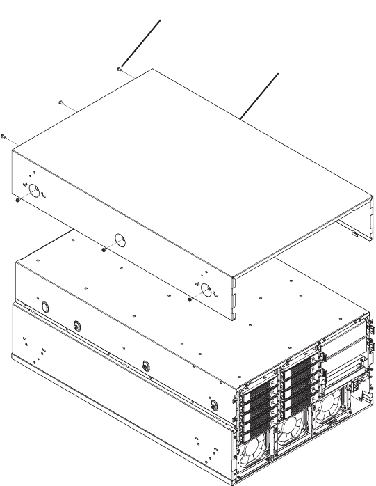
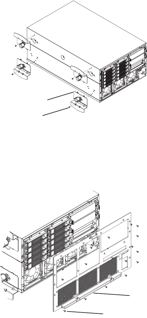
Preventing static electricity discharge . . . . . . . . . . . . . . . . . . . . . . . . . . . . . . . . . . . . . . . . . 65
Opening the server case . . . . . . . . . . . . . . . . . . . . . . . . . . . . . . . . . . . . . . . . . . . . . . . . . . . 66
Removing and installing the processor air baffle . . . . . . . . . . . . . . . . . . . . . . . . . . . . . . . . . 67
Removing and installing the center brace . . . . . . . . . . . . . . . . . . . . . . . . . . . . . . . . . . . . . . 69
Closing the server case . . . . . . . . . . . . . . . . . . . . . . . . . . . . . . . . . . . . . . . . . . . . . . . . . . . . 72
Installing drives . . . . . . . . . . . . . . . . . . . . . . . . . . . . . . . . . . . . . . . . . . . . . . . . . . . . . . . . . . . 73
Installing and removing the CD or DVD drive . . . . . . . . . . . . . . . . . . . . . . . . . . . . . . . . 73
Installing a fixed, removable-media drive in a 5.25-inch drive bay . . . . . . . . . . . . . . . . 77
Installing a hot-swap hard drive . . . . . . . . . . . . . . . . . . . . . . . . . . . . . . . . . . . . . . . . . . . 80
Removing and installing the control panel . . . . . . . . . . . . . . . . . . . . . . . . . . . . . . . . . . . . . . 84
Memory . . . . . . . . . . . . . . . . . . . . . . . . . . . . . . . . . . . . . . . . . . . . . . . . . . . . . . . . . . . . . . . . . 85
Installing and removing memory boards . . . . . . . . . . . . . . . . . . . . . . . . . . . . . . . . . . . . 85
Installing and removing DIMMs . . . . . . . . . . . . . . . . . . . . . . . . . . . . . . . . . . . . . . . . . . 91
Configuring memory options . . . . . . . . . . . . . . . . . . . . . . . . . . . . . . . . . . . . . . . . . . . . . 95
PCI expansion cards . . . . . . . . . . . . . . . . . . . . . . . . . . . . . . . . . . . . . . . . . . . . . . . . . . . . . . 98
Hot installation or removal of PCI expansion cards . . . . . . . . . . . . . . . . . . . . . . . . . . . 99
Cold installation or removal of PCI expansion cards . . . . . . . . . . . . . . . . . . . . . . . . . 104
Fibre channel module . . . . . . . . . . . . . . . . . . . . . . . . . . . . . . . . . . . . . . . . . . . . . . . . . . . . . 106
Operating system driver installation and configuration . . . . . . . . . . . . . . . . . . . . . . . . 107
Fibre channel HBA manager software . . . . . . . . . . . . . . . . . . . . . . . . . . . . . . . . . . . . 108
Installing or removing the fibre channel module . . . . . . . . . . . . . . . . . . . . . . . . . . . . . 108
Processors . . . . . . . . . . . . . . . . . . . . . . . . . . . . . . . . . . . . . . . . . . . . . . . . . . . . . . . . . . . . . 111
Special handling of Intel Xeon processors . . . . . . . . . . . . . . . . . . . . . . . . . . . . . . . . . 111
Installation and removal of processors . . . . . . . . . . . . . . . . . . . . . . . . . . . . . . . . . . . . 111
Processor VRM requirements . . . . . . . . . . . . . . . . . . . . . . . . . . . . . . . . . . . . . . . . . . . 118
Installing an Intel Management Module (IMM) . . . . . . . . . . . . . . . . . . . . . . . . . . . . . . . . . 124
Installing and removing the ROMB (RAID on Motherboard) activation key and dedicated RAID
memory . . . . . . . . . . . . . . . . . . . . . . . . . . . . . . . . . . . . . . . . . . . . . . . . . . . . . . . . . . . . . . 126
Installing and removing the Smart Battery . . . . . . . . . . . . . . . . . . . . . . . . . . . . . . . . . 129
Power subsystem . . . . . . . . . . . . . . . . . . . . . . . . . . . . . . . . . . . . . . . . . . . . . . . . . . . . . . . . 133
Replacing a power supply module . . . . . . . . . . . . . . . . . . . . . . . . . . . . . . . . . . . . . . . 134
Replacing a power distribution board . . . . . . . . . . . . . . . . . . . . . . . . . . . . . . . . . . . . . 136
Replacing the SCSI hot-swap backplane . . . . . . . . . . . . . . . . . . . . . . . . . . . . . . . . . . . . . 139
Replacing the front panel I/O board . . . . . . . . . . . . . . . . . . . . . . . . . . . . . . . . . . . . . . . . . . 143
Replacing a hot-swap fan . . . . . . . . . . . . . . . . . . . . . . . . . . . . . . . . . . . . . . . . . . . . . . . . . 145
Replacing the CMOS battery . . . . . . . . . . . . . . . . . . . . . . . . . . . . . . . . . . . . . . . . . . . . . . . 147
Replacing the system board . . . . . . . . . . . . . . . . . . . . . . . . . . . . . . . . . . . . . . . . . . . . . . . 149
8510702.book Page ii Thursday, July 7, 2005 11:21 AM
iii
www.gateway.com
5 Using the BIOS Setup Utility . . . . . . . . . . . . . . . . . . . . . . . . . . . . . . . . . . . . . . . . 153
Opening the BIOS Setup utility . . . . . . . . . . . . . . . . . . . . . . . . . . . . . . . . . . . . . . . . . . . . . 154
Updating the BIOS . . . . . . . . . . . . . . . . . . . . . . . . . . . . . . . . . . . . . . . . . . . . . . . . . . . . . . . 155
Rolling BIOS . . . . . . . . . . . . . . . . . . . . . . . . . . . . . . . . . . . . . . . . . . . . . . . . . . . . . . . . 155
Recovering the BIOS . . . . . . . . . . . . . . . . . . . . . . . . . . . . . . . . . . . . . . . . . . . . . . . . . . 156
Resetting the BIOS . . . . . . . . . . . . . . . . . . . . . . . . . . . . . . . . . . . . . . . . . . . . . . . . . . . 158
Resetting BIOS passwords . . . . . . . . . . . . . . . . . . . . . . . . . . . . . . . . . . . . . . . . . . . . . 161
6 Configuring your RAID solutions . . . . . . . . . . . . . . . . . . . . . . . . . . . . . . . . . . . . 163
Introduction . . . . . . . . . . . . . . . . . . . . . . . . . . . . . . . . . . . . . . . . . . . . . . . . . . . . . . . . . . . . . 164
Configuring your ROMB RAID solution with the RAID BIOS Console configuration utility 165
Configuring your ROMB RAID solution with the RAID Web Console . . . . . . . . . . . . . . . 174
Web Console components . . . . . . . . . . . . . . . . . . . . . . . . . . . . . . . . . . . . . . . . . . . . . 174
Client system requirements . . . . . . . . . . . . . . . . . . . . . . . . . . . . . . . . . . . . . . . . . . . . . 175
Quick configuration steps . . . . . . . . . . . . . . . . . . . . . . . . . . . . . . . . . . . . . . . . . . . . . . 175
Registration server . . . . . . . . . . . . . . . . . . . . . . . . . . . . . . . . . . . . . . . . . . . . . . . . . . . 176
Installing the Windows Web Console . . . . . . . . . . . . . . . . . . . . . . . . . . . . . . . . . . . . . 180
Launching the Web Console . . . . . . . . . . . . . . . . . . . . . . . . . . . . . . . . . . . . . . . . . . . . . . . 184
Configuring arrays and logical drives . . . . . . . . . . . . . . . . . . . . . . . . . . . . . . . . . . . . . 187
Reclaiming hot spare disks . . . . . . . . . . . . . . . . . . . . . . . . . . . . . . . . . . . . . . . . . . . . . 190
Reconfiguring existing arrays . . . . . . . . . . . . . . . . . . . . . . . . . . . . . . . . . . . . . . . . . . . 190
7 Troubleshooting . . . . . . . . . . . . . . . . . . . . . . . . . . . . . . . . . . . . . . . . . . . . . . . . . . . . . 193
Safety guidelines . . . . . . . . . . . . . . . . . . . . . . . . . . . . . . . . . . . . . . . . . . . . . . . . . . . . . . . . 194
Error messages . . . . . . . . . . . . . . . . . . . . . . . . . . . . . . . . . . . . . . . . . . . . . . . . . . . . . . . . . 195
Troubleshooting . . . . . . . . . . . . . . . . . . . . . . . . . . . . . . . . . . . . . . . . . . . . . . . . . . . . . . . . . 197
First steps . . . . . . . . . . . . . . . . . . . . . . . . . . . . . . . . . . . . . . . . . . . . . . . . . . . . . . . . . . 197
Battery replacement . . . . . . . . . . . . . . . . . . . . . . . . . . . . . . . . . . . . . . . . . . . . . . . . . . 197
Beep codes . . . . . . . . . . . . . . . . . . . . . . . . . . . . . . . . . . . . . . . . . . . . . . . . . . . . . . . . . . . . 199
Post error beep codes . . . . . . . . . . . . . . . . . . . . . . . . . . . . . . . . . . . . . . . . . . . . . . . . . 199
BIOS recovery beep codes . . . . . . . . . . . . . . . . . . . . . . . . . . . . . . . . . . . . . . . . . . . . . 199
Additional beep codes provided by Intel Management Modules . . . . . . . . . . . . . . . . 200
LED information . . . . . . . . . . . . . . . . . . . . . . . . . . . . . . . . . . . . . . . . . . . . . . . . . . . . . . . . . 201
Diagnostic POST LEDs . . . . . . . . . . . . . . . . . . . . . . . . . . . . . . . . . . . . . . . . . . . . . . . . 202
BIOS . . . . . . . . . . . . . . . . . . . . . . . . . . . . . . . . . . . . . . . . . . . . . . . . . . . . . . . . . . . . . . 214
CD or DVD drive . . . . . . . . . . . . . . . . . . . . . . . . . . . . . . . . . . . . . . . . . . . . . . . . . . . . . 214
Diskette drive . . . . . . . . . . . . . . . . . . . . . . . . . . . . . . . . . . . . . . . . . . . . . . . . . . . . . . . . 215
USB flash memory device . . . . . . . . . . . . . . . . . . . . . . . . . . . . . . . . . . . . . . . . . . . . . . 215
Expansion cards . . . . . . . . . . . . . . . . . . . . . . . . . . . . . . . . . . . . . . . . . . . . . . . . . . . . . 217
Hard drive . . . . . . . . . . . . . . . . . . . . . . . . . . . . . . . . . . . . . . . . . . . . . . . . . . . . . . . . . . 218
Internet . . . . . . . . . . . . . . . . . . . . . . . . . . . . . . . . . . . . . . . . . . . . . . . . . . . . . . . . . . . . . 219
Keyboard . . . . . . . . . . . . . . . . . . . . . . . . . . . . . . . . . . . . . . . . . . . . . . . . . . . . . . . . . . . 219
Memory . . . . . . . . . . . . . . . . . . . . . . . . . . . . . . . . . . . . . . . . . . . . . . . . . . . . . . . . . . . . 219
Monitor . . . . . . . . . . . . . . . . . . . . . . . . . . . . . . . . . . . . . . . . . . . . . . . . . . . . . . . . . . . . . 220
Power . . . . . . . . . . . . . . . . . . . . . . . . . . . . . . . . . . . . . . . . . . . . . . . . . . . . . . . . . . . . . . 220
8510702.book Page iii Thursday, July 7, 2005 11:21 AM
iv www.gateway.com
Processor . . . . . . . . . . . . . . . . . . . . . . . . . . . . . . . . . . . . . . . . . . . . . . . . . . . . . . . . . . . 221
Telephone support . . . . . . . . . . . . . . . . . . . . . . . . . . . . . . . . . . . . . . . . . . . . . . . . . . . . . . . 223
Before calling Gateway Customer Care . . . . . . . . . . . . . . . . . . . . . . . . . . . . . . . . . . . 223
Telephone support . . . . . . . . . . . . . . . . . . . . . . . . . . . . . . . . . . . . . . . . . . . . . . . . . . . . 224
Tutoring and training . . . . . . . . . . . . . . . . . . . . . . . . . . . . . . . . . . . . . . . . . . . . . . . . . . . . . 224
A Server Specifications . . . . . . . . . . . . . . . . . . . . . . . . . . . . . . . . . . . . . . . . . . . . . . . . 225
System specifications . . . . . . . . . . . . . . . . . . . . . . . . . . . . . . . . . . . . . . . . . . . . . . . . . . . . . 226
System board specifications . . . . . . . . . . . . . . . . . . . . . . . . . . . . . . . . . . . . . . . . . . . . . . . . 227
Fibre channel card specifications . . . . . . . . . . . . . . . . . . . . . . . . . . . . . . . . . . . . . . . . . . . . 229
Environmental specifications . . . . . . . . . . . . . . . . . . . . . . . . . . . . . . . . . . . . . . . . . . . . . . . 230
Electronic specifications . . . . . . . . . . . . . . . . . . . . . . . . . . . . . . . . . . . . . . . . . . . . . . . . . . . 231
Memory map . . . . . . . . . . . . . . . . . . . . . . . . . . . . . . . . . . . . . . . . . . . . . . . . . . . . . . . . 231
Interrupts . . . . . . . . . . . . . . . . . . . . . . . . . . . . . . . . . . . . . . . . . . . . . . . . . . . . . . . . . . . 231
Additional specifications . . . . . . . . . . . . . . . . . . . . . . . . . . . . . . . . . . . . . . . . . . . . . . . . . . . 233
B BIOS Settings . . . . . . . . . . . . . . . . . . . . . . . . . . . . . . . . . . . . . . . . . . . . . . . . . . . . . . . 235
C Field Replaceable Unit (FRU) Kits . . . . . . . . . . . . . . . . . . . . . . . . . . . . . . . . . . . 245
Available FRU kits . . . . . . . . . . . . . . . . . . . . . . . . . . . . . . . . . . . . . . . . . . . . . . . . . . . . . . . 246
D Extensible Firmware Interface (EFI) Shell . . . . . . . . . . . . . . . . . . . . . . . . . . . . 249
Introduction . . . . . . . . . . . . . . . . . . . . . . . . . . . . . . . . . . . . . . . . . . . . . . . . . . . . . . . . . . . . . 250
Basic EFI Shell commands . . . . . . . . . . . . . . . . . . . . . . . . . . . . . . . . . . . . . . . . . . . . . . . . 251
E Safety, Regulatory, and Legal Information . . . . . . . . . . . . . . . . . . . . . . . . . . . 255
Index . . . . . . . . . . . . . . . . . . . . . . . . . . . . . . . . . . . . . . . . . . . . . . . . . . . . . . . . . . . . . . . . . . . . 265
8510702.book Page iv Thursday, July 7, 2005 11:21 AM

Chapter 1
1
Checking Out Your Gateway
Server
• Locating drives, ports, jacks, and controls
• Locating system board components
• Getting help
8510702.book Page 1 Thursday, July 7, 2005 11:21 AM
2www.gateway.com
Chapter 1: Checking Out Your Gateway Server
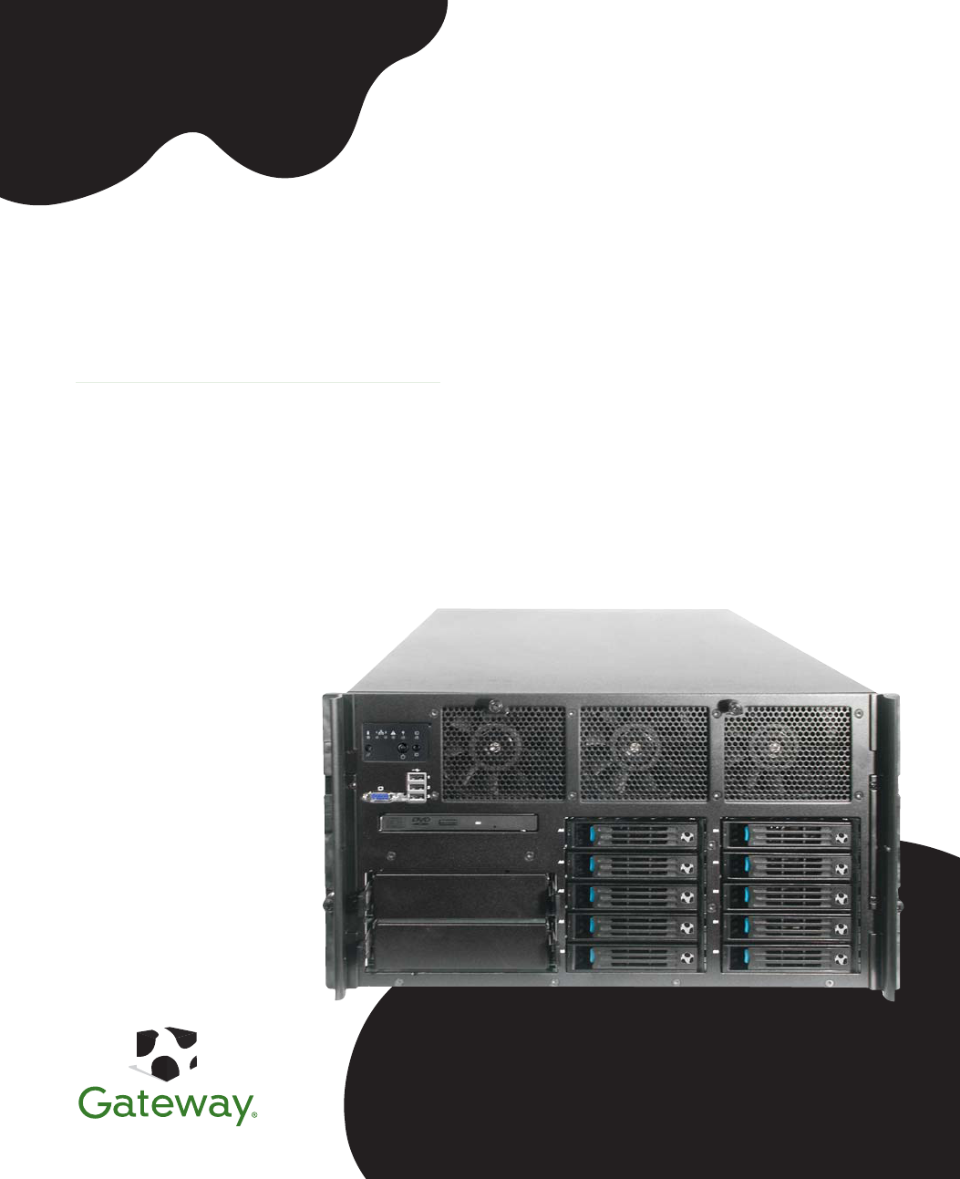
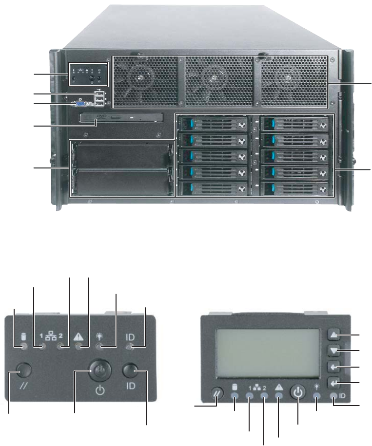
Front
Control panels
CD or
DVD
drive
USB ports
5.25-inch
drive bays
(2)
Hot-swap
hard drive
bays (10)
Video port
Control
panel Hot swap
fans
(behind
faceplate)
ID button
Reset button
NIC 1 activity LED
NIC 2 activity LED
ID LED
Power button
Hard drive
activity/fault
LED
Power/sleep LED
Status LED
Status LED
ID LED
NIC 2 activity LED
NIC 1 activity LED
Combined hard drive
activity and fault LED
Reset
button
Power button
Power/sleep LED
Scroll up
Scroll down
Back button
Select button
Standard control panel Optional control panel
8510702.book Page 2 Thursday, July 7, 2005 11:21 AM
3
www.gateway.com
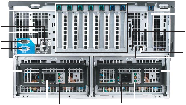
Back
Back
Serial port
Power
connector
Monitor port
PCI slots
(shown with
EMI shields)
Power connector
USB ports
Gb network
ports (2)
Power supply LEDs
Power supply
LEDs
Power supply
module latch
Power supply
module latch
RJ-45 Server
management
connector
ID LED
Fiber channel
module slot
(optional)
ID button
8510702.book Page 3 Thursday, July 7, 2005 11:21 AM
5
www.gateway.com
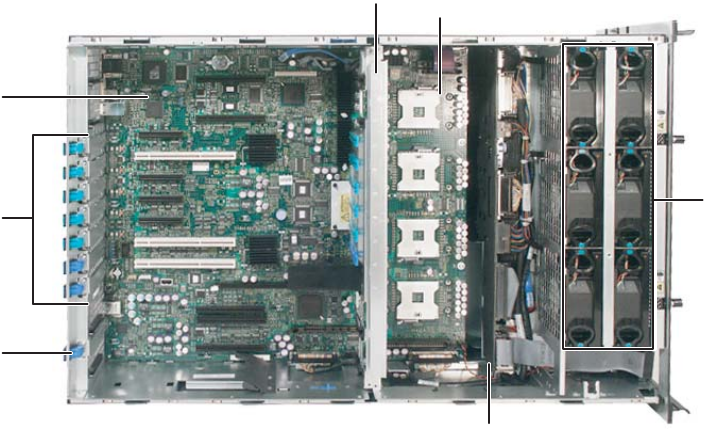
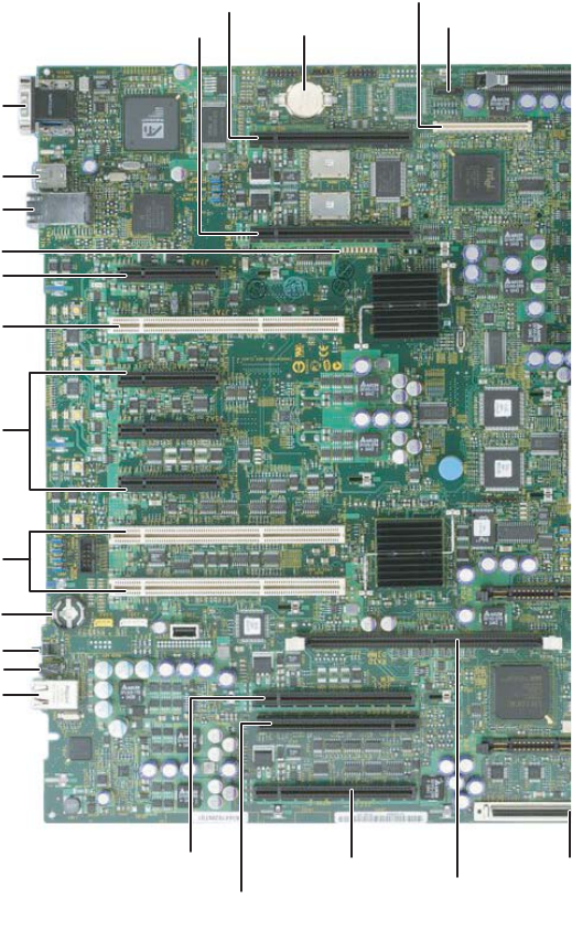
System board
System board
Left side
USB 1 and 2 connectors
SATA connector
Serial/video
connectors
Diagnostic LEDS (8)
NIC 1 and NIC 2 connectors
ID LED
PCI slot 1 Hot plug Express x8
PCI slots 6 and 7 PCI-X 100
(non-hot plug)
PCI slots 3, 4, and 5
Hot plug Express x4
RJ-45 Server management port
IMM
mo
d
u
l
e
connector
ID button
Memory board A connector
PCI slot 2 Hot plug PCI-X 133
CMOS
battery
ROMB RAID activation key
Memory board B connector
Memory board D
connector
Memory board C connector
Fibre channel module connector Onboard RAID
Cache Memory
connector
8510702.book Page 5 Thursday, July 7, 2005 11:21 AM
6www.gateway.com
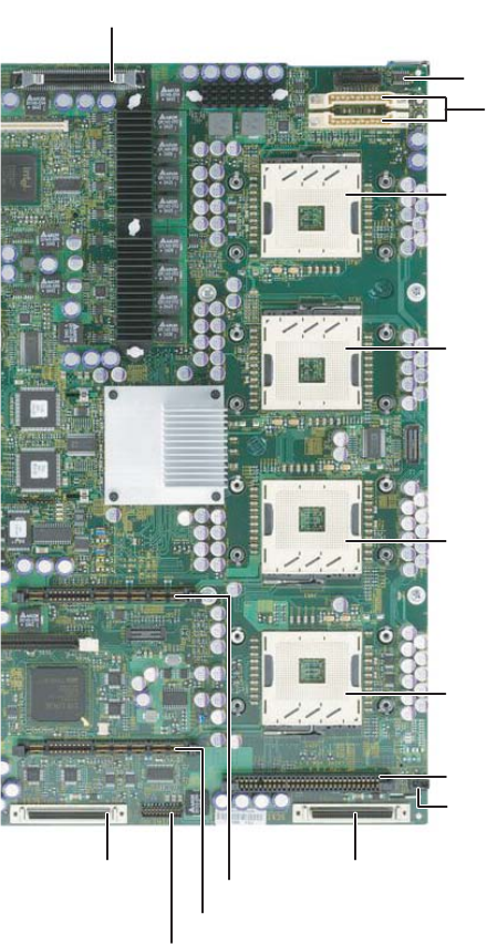
Chapter 1: Checking Out Your Gateway Server
Right side
CPU 1 socket
VRM 10.2L connector
DC power connectors
CPU 2 socket
RAID smart battery connector
SCSI channel B
connector
SCSI channel A connector
Front panel connector
Power distribution board signal connec
t
CPU 4 socket
CPU 3 socket
VRM 10.2LD connector
VRM 9.1 connector (processor cache)
Chassis intrusion connector
8510702.book Page 6 Thursday, July 7, 2005 11:21 AM

7
www.gateway.com
Getting Help
Getting Help
In addition to your operating system’s documentation, you can use the following
information resources to help you use your server.
System Companion CD
Use the System Companion CD to access file utilities, Windows 2003 Server drivers, and
documentation for your server and its components. For more information, see Using Your
System Companion CD.
Gateway Web site
Gateway provides a variety of information on its Web site to help you use your server.
Visit the Gateway Web site at support.gateway.com for:
■Technical documentation and product guides
■Technical tips and support
■Updated hardware drivers
■Order status
■Frequently asked questions (FAQs)
8510702.book Page 7 Thursday, July 7, 2005 11:21 AM

Chapter 2
9
Setting Up Your Server
• Setting up the hardware
• Protecting from power source problems
• Mounting your server into a cabinet
• Starting and turning off your server
• Setting up the operating system
• Configuring SCSI features
8510702.book Page 9 Thursday, July 7, 2005 11:21 AM

10 www.gateway.com
Chapter 2: Setting Up Your Server
Setting up the hardware
To make sure that your working environment is safe:
■Use a clean, dry, flat, stable surface for your server. Allow at least 6 inches at the back
of the server for cabling and air circulation.
■Use the instructions on your server’s setup poster to set up your hardware.
■Use an uninterruptible power supply (UPS) with surge protection for protection from
power outages and power spikes.
■Avoid subjecting your server to extreme temperature changes. Do not expose your
server to direct sunlight, heating ducts, or other heat-generating objects. Damage
caused by extreme temperatures is not covered by your warranty. As a general rule,
your server is safest at temperatures that are comfortable for you.
■Keep your server and magnetic media away from equipment that generates magnetic
fields, such as unshielded stereo speakers. Strong magnetic fields can erase data on
both diskettes and hard drives. Even a telephone placed too close to the server may
cause interference.
Mounting your server into a cabinet
The cabinet mounting hardware included with your server should be used with standard
4-post cabinets that have front and back vertical posts. If your cabinet is a different type,
obtain mounting hardware from the cabinet manufacturer.
Refer to the documentation that comes with the rackmount rail kit for installation
instructions.
Warning
Your server comes with a 3-wire AC power cords fitted with the correct
plug style for your region. If these plugs do not match the connector
on your UPS or wall outlet, do not attempt to modify the plugs in any
way. Use a UPS or wall outlet that is appropriate for the supplied
AC power cords.
Warning
Lifting the server and attaching it to the rack is a two-person job. If
needed, use an appropriate lifting device. A fully loaded Gateway
9715 server weighs about 130 lbs (60 kg).
Caution
Before attaching cabinet accessories, make sure that the server is
turned off and all power cords are unplugged.
Caution
The cabinet must provide sufficient airflow to the front of the server
to maintain correct cooling.
8510702.book Page 10 Thursday, July 7, 2005 11:21 AM

11
www.gateway.com
Setting up the hardware
Converting to pedestal configuration
To convert your server to a pedestal configuration, you need a pedestal conversion kit. To
order the conversion kit, contact Gateway Customer Care, Gateway Sales, or visit
accessories.gateway.com. For more information on contacting Customer Care, see
“Telephone support” on page 223.
Contents of the conversion kit
The pedestal conversion kit contains the following:
■Outer cover (1)
■Phillips screws (6)
■Caster assemblies (4)
■Pedestal face plate (1)
■Torx screws (6)
Tools required
You need the following tools to convert to the pedestal configuration:
■Phillips head screwdriver (#2)
■Torx screwdriver
To convert your server to the pedestal configuration:
1Follow the instructions in “Preventing static electricity discharge” on page 65.
2Remove the server from the rack cabinet, if necessary.
3Remove the slide rails and cable management arm (if installed).
4Remove the optional control panel (if installed), by following the instructions in
“Removing and installing the control panel” on page 84.
Warning
Lifting the server or removing it from the rack is a two-person job. If
needed, use an appropriate lifting device. A fully loaded Gateway
9715 server weighs about 130 lbs (60 kg).
8510702.book Page 11 Thursday, July 7, 2005 11:21 AM
12 www.gateway.com
Chapter 2: Setting Up Your Server
5Turn the server over so the bottom is facing up, then position the outer cover, supplied
with the conversion kit, on the bottom of the chassis.
6Align the screw holes in the outer cover with the holes in the chassis and secure with
the six screws provided with the kit.
Outer cover
Screw
8510702.book Page 12 Thursday, July 7, 2005 11:21 AM
13
www.gateway.com
Setting up the hardware
7Align each of the casters with its screw hole on the (new) bottom of the server and
secure with one Phillips screw per caster (provided with caster assembly).
8Remove the Torx screws securing the rack faceplate to the front of the chassis, then
remove the faceplate.
9Align the screw holes in the pedestal faceplate with the holes on the front of the
chassis, then secure with the Torx screws you previously removed.
Insert and partially tighten four screws before inserting the remaining screws, then
fully tighten the screws.
Caster
Screw
Faceplate
Torx Screw
8510702.book Page 13 Thursday, July 7, 2005 11:21 AM

14 www.gateway.com
Chapter 2: Setting Up Your Server
10 Reinstall the optional control panel by following the instructions in “Removing and
installing the control panel” on page 84.
11 Set the server upright on its casters and reconnect the data and power cables.
8510702.book Page 14 Thursday, July 7, 2005 11:21 AM

15
www.gateway.com
Protecting from power source problems
Protecting from power source problems
Surge protectors, line conditioners, and uninterruptible power supplies can help protect
your server against power source problems.
Surge protectors
During a power surge, the voltage level of electricity coming into your server can increase
to far above normal levels and cause data loss or server damage. Protect your server and
peripheral devices by connecting them to a surge protector, which absorbs voltage surges
and prevents them from reaching your server.
When you purchase a surge protector:
■Make sure that the surge protector meets the appropriate product safety certification
for your location, such as Underwriters Laboratories (UL).
■Check the maximum amount of voltage the protector allows to pass through the line.
The lower the voltage, the better the protection for your server.
■Check the energy absorption (dissipation) rating. The higher the energy absorption
rating, the better the protection for your server.
Line conditioners
A line conditioner protects your server from the small fluctuations in voltage from an
electrical supply. Most servers can handle this variation, called line noise, without problems.
However, some electrical sources include more line noise than normal. Line noise can also
be a problem if your server is located near, or shares a circuit with, a device that causes
electromagnetic interference, such as a television or a motor.
Some surge protectors and uninterruptible power supplies include simple line-conditioning
capabilities.
Uninterruptible power supplies
Use an uninterruptible power supply (UPS) to protect your server from data loss during a
total power failure. A UPS uses a battery to keep your server running temporarily during
a power failure and lets you save your work and shut down your server. You cannot run
your server for an extended period of time while using only the UPS. To buy a UPS, visit
accessories.gateway.com.
Caution
High voltages can enter your server through the power cord, and the
modem and network connections. Protect your server by using a
surge protector. If you have a modem, use a surge protector that has
the appropriate type of modem jack. During an electrical storm,
unplug the surge protector and the modem and network cables.
8510702.book Page 15 Thursday, July 7, 2005 11:21 AM
16 www.gateway.com
Chapter 2: Setting Up Your Server
Starting your server
Before you start your server for the first time:
■Make sure that the server and monitor are plugged into a power outlet or UPS and
that the UPS (if you are using one) is turned on.
■Make sure that all cables are connected securely to the correct ports and jacks on the
back of the server.
To start the server:
■Press the power button.
Important When you plug the AC power cords into the power supplies, wait for
20 to 30 seconds. The system will automatically power on for about
3 seconds, then power down. This allows the BMC to initialize the
out-of-band management capabilities.
Caution
When you connect peripheral devices to the server, make sure that
your server and devices are turned off and the power cords are
unplugged.
Power button
Power/sleep LED
Power button
Power/sleep LED
Standard control panel Optional control panel
8510702.book Page 16 Thursday, July 7, 2005 11:21 AM
17
www.gateway.com
Starting your server
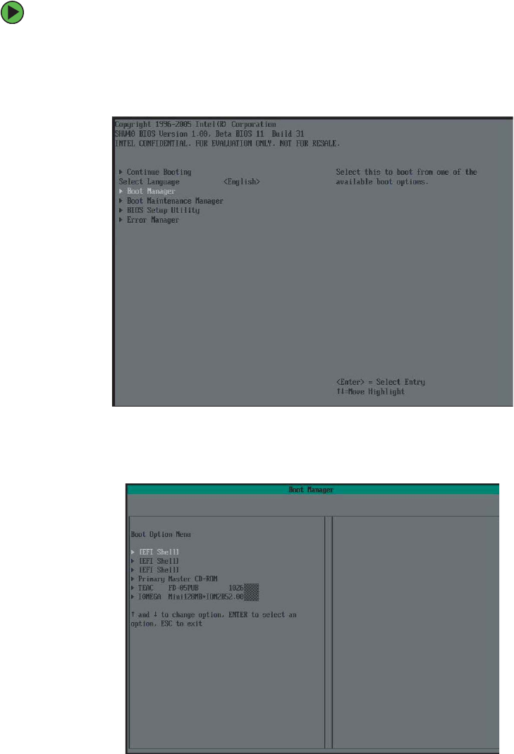
Normally, the server fans start and the POST begins running (you can follow the boot
progress on the monitor). The SCSI BIOS scan is displayed, followed by the Gateway
logo screen. The Gateway logo screen contains the BIOS version and copyright
information. Press any key to access the System Options menu.
The System Options menu contains the following options. Press the up and down
arrow keys to highlight your selection, then press ENTER to select:
■Continue Booting - Selected by default (will occur automatically, after a pre-set time
period.
■Boot Manager - Lets you select from one of the available boot options. The server
will attempt boot from the first device on the list. If the first device is not available,
it will continue down the list until it reaches an available device. To modify these
Boot Options, select the Boot Maintenance Manager (described below).
When the power/sleep LED is... It means...
Green The server is turned on.
Off The server is turned off (if ACPI is off).
Slowly blinking Low power state — S1 (if ACPI is on).
Off Low power state — S4/S5 (if ACPI is on).
Important During the POST sequence, it takes from 3 to 10 minutes to see the
first screen. This is normal and does not indicate an error or problem.
8510702.book Page 17 Thursday, July 7, 2005 11:21 AM
18 www.gateway.com
Chapter 2: Setting Up Your Server
■Boot Maintenance Manager - A menu of choices that lets you configure boot options
and boot environment variables.
■BIOS Setup Utility - Lets you configure the server BIOS settings.
■POST Error Manager - Lets you view POST errors detected by the system.
If nothing happens when you press the power button:
■If your server is plugged into a UPS, make sure that the UPS is connected securely
to an electrical outlet, turned on, and working correctly.
■Make sure that the monitor is connected to the server, plugged into the power
outlet or UPS, and turned on. You may also need to adjust the monitor’s brightness
and contrast controls.
Selecting the boot device
To select which device your server boots from:
1During server startup, press any key to access the System Options Menu.
2Press the up and down arrow keys to select Boot Manager from the System Options
Menu, then press ENTER. The Boot menu opens.
Important The first time you turn on the server, any pre-installed operating
system may begin asking you for configuration settings. See your
operating system’s documentation for instructions on configuring
advanced settings for your specific network.
8510702.book Page 18 Thursday, July 7, 2005 11:21 AM

19
www.gateway.com
Starting your server
3Press the up and down arrow keys to select the device you want to boot from, then
press ENTER. Common choices include:
■Removable Dev. (Removable device)
■ATAPI CDROM (CD or DVD drive)
■Hard Drive
■IBA GE NIC (Network boot)
Understanding the power-on self-test
When you turn on your server, the power-on self-test (POST) routine checks the server
memory and components. If POST finds any problems, the server displays error messages.
Write down any error messages that you see, then see “Error messages” on page 195 and
“Post error beep codes” on page 199 for troubleshooting information.
8510702.book Page 19 Thursday, July 7, 2005 11:21 AM
20 www.gateway.com
Chapter 2: Setting Up Your Server
Controlling your server
Local control
Your server can be controlled locally by installing a USB keyboard and a USB mouse. There
are USB connectors, as well as video connectors, on both the front and back of the server.
There are no PS/2 connectors on this server.
Remote control
The BIOS supports redirection of both video and keyboard through a serial link (COM port)
on this server. When console redirection is enabled, local (host server) keyboard input and
video output are passed both to the local keyboard and video connections and to the
remote console through the serial link. Keyboard inputs from both sources are considered
valid and video is displayed to both outputs.
With console redirection, you can control the server without a host keyboard or monitor
attached to the server, and you can run the server entirely by remote control, including
setup and other text-based utilities.
Serial configuration settings
When redirecting through a modem (instead of a null modem cable), the modem needs
to be configured as follows:
■Auto-answer (for example, ATS0=2, to answer after two rings).
■Modem reaction to DTR set to return to command state (for example, AT&D1) - failure
to provide this setting results in the modem either dropping the link when the server
reboots (as in AD&D0) or becoming unresponsive to server baud rate changes (as in
AT&D2).
■Handshake must be set to CTS/RTS + CD for optimum performance - If EMP is sharing
the COM port with serial redirection, the handshaking must be set to Xon/Xoff + CD.
An EMP option utilizing CD should not be used if a modem is not used and the CD
is not connected.
■Both EMP and console redirection require N, 8, 1 mode (no parity, 8-bit dta, 1 stop bit).
The BIOS does not require that the splash logo be turned off for console redirection to
function. The BIOS supports multiple consoles, some of which are in graphics mode and
some in text mode. The graphics consoles can display the logo while the text consoles
receive the redirected text.
Console redirection ends at the beginning of the Legacy OS boot (INT 19h).
8510702.book Page 20 Thursday, July 7, 2005 11:21 AM

21
www.gateway.com
Controlling your server
Keystroke mappings
During console redirection, the remote terminal (which may be a dumb terminal or a
system with a modem running a communication program) sends keystrokes to the local
server. The local server passes video back over this same link. The keystroke mappings
follow VT-UTF8 format with the following extensions.
Setting up alias keys
The DEL and CTRL + (function key) combinations are synonyms for the F2 or Setup key.
These are not prompted for in screen messages. These hotkeys are defined only for console
redirection support and are not used on locally attached keyboards.
Standalone ESC key for headless operation
To complete an escape sequence, the timeout must be two seconds for entering additional
characters following an escape.
■ESC followed by a two-second pause is interpreted as a single escape.
■ESC followed within two seconds by one or more characters that are not forming a
sequence described in this document are interpreted as ESC + the character, or
characters, not an escape sequence.
All of the escape sequences in the following table are input sequences, that is, they are
sent to the BIOS from the remote terminal.
Escape Sequence Description
ESC + R + ESC + R + ESC + R
This will implement but will default to “disabled.”
REmote console reset
ESC + (BMC Mux switch escape sequence
ESC + CDZi + (terminal-type-number) Dynamic Terminal Type choice, where:
0 = PC-ANSI (the only current terminal type)
1 = VT100 (not implemented, but honored as VT100+)
2 = VT100+
3 = VT-UTF8
ESC + CDZ0 Inhibit console redirection
ESC + CDZ1 Restart console redirection
ESC + CDZ2 “Soft” inhibit console redirection, without serial port or
modem reset.
8510702.book Page 21 Thursday, July 7, 2005 11:21 AM

22 www.gateway.com
Chapter 2: Setting Up Your Server
Limitations
The BIOS console redirection terminates after an EFI-aware operating system calls EFI Boot
Service ExitBootServices. The operating system is responsible for continuing the console
redirection after that point. BIOS console redirection is a text console and any graphical
data, such as a logo, is not redirected.
Interface to server management
If the BIOS determines that console redirection is enabled, it passes the baud rate through
the IPMB (Intelligent Platform Management Bus) to the appropriate management controller.
Example setup for console redirection
The following is an example of how to configure the console/host and server for console
redirection. In this example, the console is running under Windows. The console and
server are directly connected through the serial ports of both systems using a serial null
modem cable.
To redirect the server console:
1Turn on the server.
2Press the up and down arrow keys to select BIOS Setup from the System Options Menu,
then press ENTER. The BIOS setup utility menu opens.
3Press the up and down arrow keys to select Server Management menu, then press ENTER.
The Server Management menu opens.
4Press the up and down arrow keys to select Console Redirection, then select COM1
Console Redirection.
5Make the following settings:
■Set Console Redirect to Enabled
■Set Connection Type to Direct
■Set Baud Rate to 115.2K
■Set the Flow Control to CTS/RTS
■Set the Terminal Type to VT-UTF8
6Press F10, then select Yes to save the changes and exit the BIOS Setup utility.
7Press ENTER to confirm. The server reboots and console redirection is enabled.
8Turn off the server and configure the console.
8510702.book Page 22 Thursday, July 7, 2005 11:21 AM

23
www.gateway.com
Controlling your server
To configure the console:
1Turn on the console system and let the operating system start.
2Click Start, All Programs, Accessories, Communications, then click Hyperterminal.
3When the Connection Description window opens, enter Guest in the Name field, then
click OK.
4When the Connect To window opens, click the COM port of the console to which the
null modem cable is connected (for example, COM1).
5When the COM1 Properties window opens, make the following settings:
■Bits per second to 115200
■Flow control to Hardware (CTS/RTS)
■Leave the other settings at their default values
6Click OK to accept the settings and enter the hyperterminal screen.
7Turn on the server. The console starts displaying the redirection after the video on
the server synchronizes.
8510702.book Page 23 Thursday, July 7, 2005 11:21 AM

24 www.gateway.com
Chapter 2: Setting Up Your Server
Turning off your server
Every time you turn off your server, first shut down the operating system. You may lose
data if you do not follow the correct procedure.
To turn off the server:
1See the operating system’s documentation or online help for instructions on shutting
down the operating system. Whenever possible, you should use the operating system’s
shut down procedure instead of pressing the power button.
2If your server did not turn off automatically, press and hold the power button until
the server turns off.
Warning
The power button on the server does not turn off server AC power.
To remove AC power from the server, you must unplug both
AC power cords from the wall outlet or power source. The power
cords are considered the disconnect device to the main (AC) power.
Caution
If you routinely turn off your server (daily or weekly), do not unplug
the server or use the On/Off switch on the UPS. Regularly cutting
off all power to your server may cause the CMOS battery to fail
prematurely.
8510702.book Page 24 Thursday, July 7, 2005 11:21 AM
25
www.gateway.com
Setting up the operating system
Setting up the operating system
If you ordered your server with the operating system already installed by Gateway, in most
cases it is completely installed and the basic settings are already configured. The Windows
Small Business Server operating system may require additional installation, depending on
the version you ordered. See your operating system’s documentation for instructions on
completing the installation or configuring advanced settings for your specific network.
If you are installing an operating system because it was not already installed by Gateway,
see the appropriate installation guide for instructions.
8510702.book Page 25 Thursday, July 7, 2005 11:21 AM
26 www.gateway.com
Chapter 2: Setting Up Your Server
Initial hardware settings
Your server comes from the manufacturer with the correct initial hardware settings to
operate your server as configured. However, at some point you might want to change
settings to reflect a tasking change, a change in security requirements, or the addition of
new resources to your server.
General hardware settings, as well as the onboard LSI RAID solution, can be changed by
using the BIOS Setup utility, and advanced RAID settings for the Intel ROMB RAID solution
can be changed by using the RAID BIOS Console or Web Console (or the specific RAID
console which accompanied a customized, add-in RAID solution).
For information on the BIOS Setup utility, see “Using the BIOS Setup Utility” on page 153.
For information on BIOS settings, see “BIOS Settings” on page 235. For information on
the RAID BIOS Console utility, see “Configuring your RAID solutions” on page 163. For
information on a specific RAID console for an add-in RAID solution, see the documentation
on that hardware which accompanied your server.
8510702.book Page 26 Thursday, July 7, 2005 11:21 AM
27
www.gateway.com
Configuring SCSI features
Configuring SCSI features
The LSI Logic MPT SCSI Setup Utility lets you configure your server’s SCSI features. For
information on configuring your RAID solutions, see “Configuring your RAID solutions”
on page 163.
To access the LSI Logic MPT SCSI Setup Utility:
1Press CTRL + C during POST, right after the memory test but prior to entering the
System Options menu. The LSI Logic MPT SCSI Setup Utility main menu screen opens.
2Press F2 to access the menu bar at the top of the screen, then press the HOME and
END keys to select either the Boot Adapter List or Global Properties.
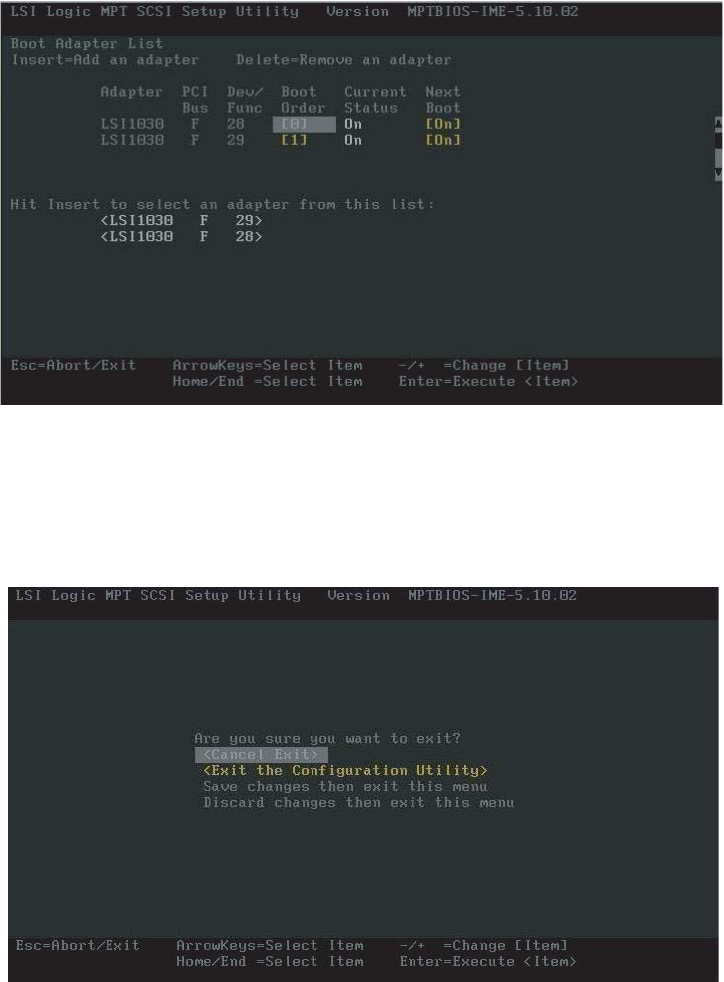
To access and change the Boot Adapter List:
1Follow the instructions in “To access the LSI Logic MPT SCSI Setup Utility:” on page 27.
8510702.book Page 27 Thursday, July 7, 2005 11:21 AM
28 www.gateway.com
Chapter 2: Setting Up Your Server
2Press F2 to access the menu bar at the top of the screen, then press the HOME and
END keys to select the Boot Adapter List. The Boot Adapter List screen opens.
This list lets you add or remove boot adapters by highlighting the boot adapter and
pressing the + or - key to change the status.
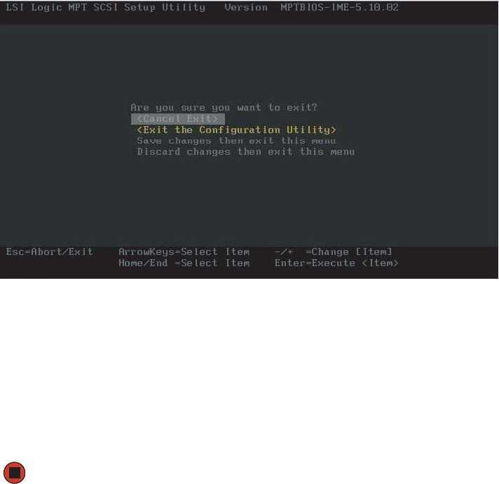
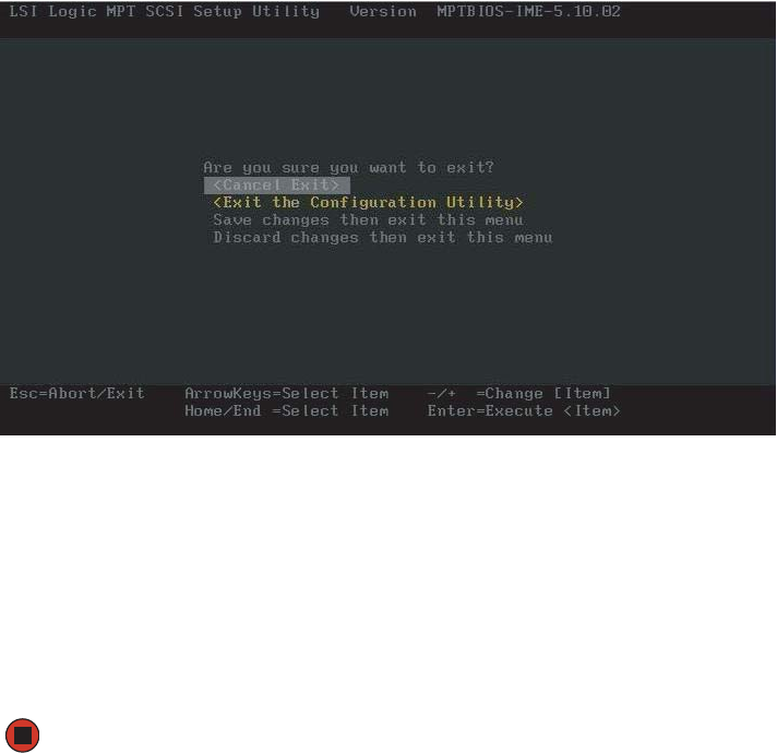
3If you do not want to make any changes, press ESC to exit the utility.
- OR -
When you are finished adding or removing boot adapters, press ENTER, The Exit menu
screen will open.
8510702.book Page 28 Thursday, July 7, 2005 11:21 AM
29
www.gateway.com
Configuring SCSI features
4Use the up and down arrow keys to select one of the following options:
■Cancel Exit - To cancel the exit and return to the adapter or device properties screen.
■Save Changes then exit this menu - To save your changes and exit the menu.
■Discard changes then exit this menu - To discard your changes and exit the menu.
■Exit the Configuration Utility - To exit the utility entirely.
If you made changes, the system will reboot when you exit the utility.
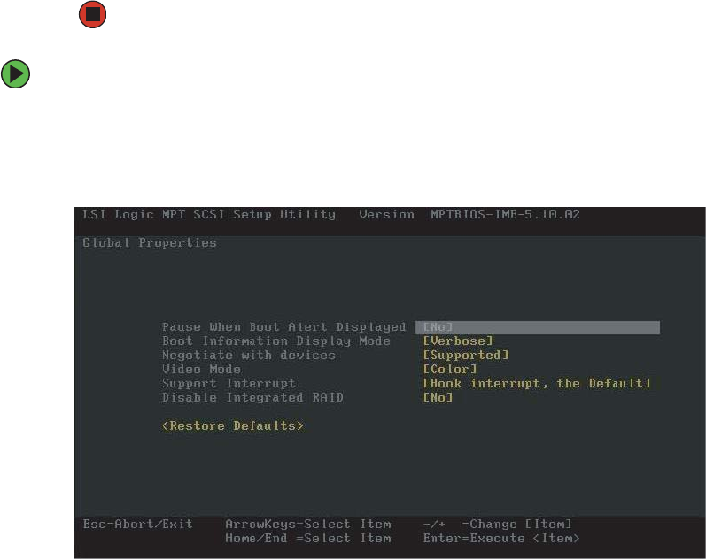
To access and change the Global Properties List:
1Follow the instructions in “To access the LSI Logic MPT SCSI Setup Utility:” on page 27.
2Press F2 to access the menu bar at the top of the screen, then press the HOME and
END keys to select the Global Properties List. The Global Properties List screen opens.
3Use the up and down arrow keys to select options from the list and +/- to change
the settings:
■Pause when boot alert displayed (Yes or No)
■Boot information display mode (Verbose or Terse)
■Negotiate with Devices (Supported or All)
■Video Mode (Color or Monochrome)
8510702.book Page 29 Thursday, July 7, 2005 11:21 AM
30 www.gateway.com
Chapter 2: Setting Up Your Server
■Disable Integrated RAID (No or Yes)
■Support Interrupt (Hook Interrupt (default) or Bypass Interrupt Hook)
■<Restore Defaults> (to restore the default configuration of the adapters)
4Press ESC to discard your changes and exit.
- OR -
When you are finished making changes, press ENTER, The Exit menu screen will open.
5Use the up and down arrow keys to select one of the following options:
■Cancel Exit - To cancel the exit and return to the adapter or device properties screen.
■Save Changes then exit this menu - To save your changes and exit the menu.
■Discard changes then exit this menu - To discard your changes and exit the menu.
■Exit the Configuration Utility - To exit the utility entirely.
If you made changes, the system will reboot when you exit the utility.
8510702.book Page 30 Thursday, July 7, 2005 11:21 AM
31
www.gateway.com
Configuring SCSI features
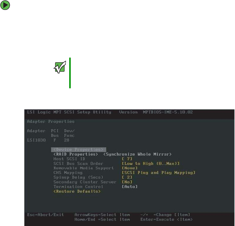
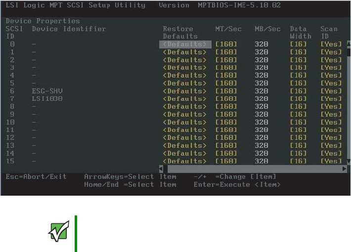
To access and change the Adapter Properties List:
1Follow the instructions in “To access the LSI Logic MPT SCSI Setup Utility:” on page 27.
2Use the up and down arrow keys to highlight the adapter to be configured, then press
ENTER. The following message will be displayed:
Scanning for devices...
When the utility is finished scanning for devices, the Adapter Properties screen opens.
3Use the up and down arrow keys to select options from the list and +/- to change
the settings:
■<Device Properties> Takes you to the Device Properties screen
■Host SCSI ID (0 to 15)
■SCSI Bus Scan Order (Low to High (0 - Max) or High to Low (Max - 0))
■Removable Media Support (None, Boot Drive Only, or With Media Installed)
■CHS (Cylinder Head Sector) Mapping (SCSI Plug and Play Mapping or Alternate CHS
Mapping)
■Spinup Delay (Secs) (1 to 15)
Important If the RAID on MotherBoard (ROMB) feature is not enabled, the
following message will be displayed:
Current firmware does not support IME RAID type. Press any
key to continue.
8510702.book Page 31 Thursday, July 7, 2005 11:21 AM
32 www.gateway.com
Chapter 2: Setting Up Your Server
■Secondary Cluster Server (No or Yes)
■Termination Control (Auto)
■<Restore Defaults> (to discard the changes and restore the default configuration
of the adapters)
4If you selected anything but <Device Properties>, go to Step 6.
- OR -
If you selected <Device Properties>, press ENTER. The Device Properties screen opens.
5Use the up and down arrow keys to select options from the list and +/- to change
the settings:
■MB/Sec (320)
■MT/Sec (0 or 5, 10, 20, 40, 80, 160)
■Data Width (16 or 8)
■Scan ID (Yes or No)
■Scan Luns >0 (Yes or No)
Important The Device Properties screen is large and requires the use of the
arrow keys (or scroll bars) to scroll left and to scroll down to see all
of the configuration options.
8510702.book Page 32 Thursday, July 7, 2005 11:21 AM
33
www.gateway.com
Configuring SCSI features
■Disconnect (On or Off)
■SCSI Timeout (<10>)
■Queue Tags (On or Off)
■<Restore Defaults> (to discard the changes and restore the default configuration)
6Press ESC to discard your changes and exit.
- OR -
When you are finished making changes, press ENTER, The Exit menu screen will open.
7Use the up and down arrow keys to select one of the following options:
■Cancel Exit - To cancel the exit and return to the adapter or device properties screen.
■Save Changes then exit this menu - To save your changes and exit the menu.
■Discard changes then exit this menu - To discard your changes and exit the menu.
■Exit the Configuration Utility - To exit the utility entirely.
If you made changes, the system will reboot when you exit the utility.
8510702.book Page 33 Thursday, July 7, 2005 11:21 AM

Chapter 3
35
Managing and Maintaining
Your Server
• Managing your server and network
• Preparing for system recovery
• Caring for your server
8510702.book Page 35 Thursday, July 7, 2005 11:21 AM
36 www.gateway.com
Chapter 3: Managing and Maintaining Your Server
System administration
Gateway Server Manager
Gateway Server Manager lets you manage multiple computers on a Windows network from
a single window, then implement commands and policies across the network with a single
action. With Gateway Server Manager, you can run system management tasks which are
triggered by certain events or conditions.
Printed documentation comes with the Gateway Server Manager CD. You can find additional
documentation in the program’s online help.
Local control panel
This optional feature provides an intelligent front panel for your server and lets you
configure the server, monitor system status, and control the server from the panel. The
LCD panel has its own microcontroller and is independent of the operating system. Its
4×20 display provides information directly from the Baseboard Management Controller
(BMC) using the IPMB bus.
Interactions
The local control panel can:
■Poll the BMC to determine alert conditions
■Query the BMC for system event log entries
■Display and control the power state of the server
■Query the BMC for field replaceable units (FRUs)
■Read BMC sensors
■Retrieve BIOS POST progress codes
■Issue IPMI commands to the BMC
■Obtain BIOS-specific information from the BMC
In addition to the above, system software can also interact with the LCP to:
■Write characters to the LCP
■Read characters from the LCP
■Read the state of the LCP buttons
■Control the LCP buttons
■Change LCP menus
8510702.book Page 36 Thursday, July 7, 2005 11:21 AM
37
www.gateway.com
System administration
■Read information from the LCP microcontroller
■Update the LCP firmware
Navigation
The following table shows the LCP menu options:
Menu Options Description
Configure the
server
Network (LAN channel 1 to 3)
■IP address (BMC)
■Netmask
■Gateway address
■Enable LAN channel
Configure TCO NIC
Inventory
■CPUs
■DIMMs
■Drives
■Power supplies
■System fans
View system inventory
Scroll up button - one item up
Scroll down button - one item down
Back button
Select button
8510702.book Page 37 Thursday, July 7, 2005 11:21 AM

38 www.gateway.com
Chapter 3: Managing and Maintaining Your Server
Server name View server name
Asset tab information View asset tag
Server GUID View server GUID
BIOS revision View BIOS revision
BMC firmware revision View BMC firmware revision
Local Control Panel firmware revision View LCP firmware revision
HSC firmware revision View HSC firmware revision
HSC2 firmware revision View HSC2 firmware revision
Monitor the
server
POST progress codes View POST progress codes
Server health (drill down to subsystem(s)
at fault)
View the health of the system
System event log View the system event log
CPU sensors (CPU 1 to n)
■Presence
■Over temperature
■On/off line
View CPU related status
Chassis status
Intrusion status
Power supply 1 to n
■Presence
■Status
Fan 1 to n
■Presence
■Status
■Speed
HSC 1 to 2
■Presence
■Status
View chassis related status
Temperatures (all available temperature
sensors
View all available temperature sensor status
Menu Options Description
8510702.book Page 38 Thursday, July 7, 2005 11:21 AM

39
www.gateway.com
System administration
Server security
To prevent unauthorized use of the server, you can set BIOS startup passwords.
Using BIOS security passwords
Set up a supervisor password to prevent unauthorized access to the BIOS Setup utility. After
you create a supervisor password, you can set up a user password to prevent unauthorized
access to the server.
Control the
server
Boot flags (select from available boot
flags)
■Set the flag — one time reboot
■Reboot the system
Configure boot order
Power control
■Power on
■Power off (graceful or hard)
Power control
Control the power state by creating button
pushes — as if performed on the front panel
by the user.
Reset Power control
IPMI control
■Power on
■Power off (graceful or hard)
IPMI control
Send the chipset a power control command.
The same functionality as if done over LAN
or by GSM.
IPMI command screen
■Issue an IPMI command (text or hex)
Issue an IPMI command
Set up the server Language selection (display loaded
language files)
Select the LCP display language
Status setup
■Interval timing (set time to retrieve
status)
■Subsystem mask (mask off
subsystems)
Set sensor refresh interval
Password setup
■Password exists/does not exist
■Create/change password
Password setup
Remote access rights
■View (grant or deny)
■Write (grant or deny)
■Buttons (grant or deny)
Remote access control
Menu Options Description
8510702.book Page 39 Thursday, July 7, 2005 11:21 AM

40 www.gateway.com
Chapter 3: Managing and Maintaining Your Server
You can:
■Enter either password to finish starting the server.
■Enter the supervisor password to access the BIOS Setup utility.
For information about resetting BIOS passwords, see “Resetting BIOS passwords” on
page 161.
To set the BIOS security passwords:
1Restart your server, then press any key when the Gateway logo screen appears during
startup. The System Options menu opens.
2Select BIOS Setup utility, then press ENTER. The BIOS Setup utility opens.
3Select the Security menu.
4Select the password to set according to the following table.
5Type the password and press ENTER, then type it again and press ENTER.
6Save your changes and exit the BIOS Setup utility.
Option Description
Supervisor password To control access to system configuration, set a
supervisor password. Using a supervisor password lets
you make changes to any setting in the BIOS.
Passwords can be cleared. To clear the passwords, see
“Resetting BIOS passwords” on page 161.
User password The supervisor password must be set up before a user
password can be set. To control access to the server, set
a user password. The supervisor can set the level of
access granted to the user password. The user password
access levels are:
■No Access. User cannot access the BIOS Setup utility.
■Limited. User can change only the date and time.
■View Only. User can see all settings, but cannot
change them.
■Full. User can change every setting except the
supervisor password.
Passwords can be cleared. To clear the passwords, see
“Resetting BIOS passwords” on page 161.
8510702.book Page 40 Thursday, July 7, 2005 11:21 AM
41
www.gateway.com
Identifying your server
Identifying your server
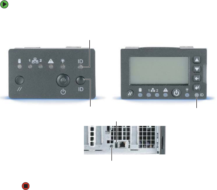
While you are working on a cabinet that contains several slim servers, it can be difficult
to keep track of which server or servers you are currently working on. The System ID
indicator is a blue LED that you can turn on to help you locate the correct server. For the
System ID indicator to turn on, the server does not need to be turned on, but it does need
to be plugged in.
To turn on the System ID indicator:
1Press the System ID button. The two blue System ID indicators turn on.
2To turn off the indicator, press the System ID button.
System ID
indicator LED
System ID button System ID
indicator LED
System ID button
System ID indicator LED
Standard control panel Optional control panel
8510702.book Page 41 Thursday, July 7, 2005 11:21 AM

42 www.gateway.com
Chapter 3: Managing and Maintaining Your Server
Creating a DOS-bootable System Update
Package (SUP) CD
Several utilities available on this server require that you boot the server to DOS. A
DOS-bootable SUP CD, containing the update files, provides a convenient way to
accomplish this.
For this process, you will need:
■A CD burner drive
■CD burning software
■A blank CD
To create a DOS-bootable SUP CD:
1Put a blank CD into your CD burner.
2Log on to your Internet connection.
3Go to www.support.gateway.com.
4Click Downloads, then Browse all downloads.
5Select Servers for Step 1.
6Select 9715 for Step 2.
7Select your operating system for Step 3.
8Select BIOS downloads for Step 4.
9Click Display results for Step 5.
10 Select the System Update Package file from the list of available files.
11 Click Download now, then select a convenient and easily found location for the file.
12 After the file downloads, find the .ISO file on your hard drive and double-click on it.
Your CD burner software will open.
13 Click to start writing to the CD. The CD created will be DOS-bootable and will contain
the latest updates for BIOS, FRU, CMOS, and so on.
Important CD burning software must be installed on your system for this process
to work.
8510702.book Page 42 Thursday, July 7, 2005 11:21 AM
43
www.gateway.com
Creating a DOS-bootable System Update Package (SUP) CD
Booting from the SUP CD:
1Restart your server, then press any key when the Gateway logo screen appears during
startup. The System Options menu opens.
2Select BIOS Setup utility, then press ENTER. The BIOS Setup utility opens.
3Use the down arrow key to select Boot Manager, then press ENTER. The Boot Option menu
opens.
8510702.book Page 43 Thursday, July 7, 2005 11:21 AM

44 www.gateway.com
Chapter 3: Managing and Maintaining Your Server
4Select the CD drive on the Boot Options menu, then press ENTER. The server will now
boot to the CD drive. If the CD drive is not detected, see “CD or DVD drive” on
page 214.
5Insert the bootable CD into the CD drive.
6Exit the System Options menu and let the server continue to boot.
7After the updates are completed, restart your server, then press any key when the
Gateway logo screen appears during startup. The System Options menu opens.
8Select BIOS Setup utility, then press ENTER. The BIOS Setup utility opens.
9Use the down arrow key to select Boot Manager, then press ENTER. The Boot Option menu
opens.
10 Select your normal boot drive from the list, then press ENTER. The server will now
boot normally.
8510702.book Page 44 Thursday, July 7, 2005 11:21 AM
45
www.gateway.com
Baseboard Management Controller (BMC)
Baseboard Management Controller (BMC)
The Baseboard Management Controller (BMC) monitors system platform management
events and logs their occurrences in the non-volatile System Event Log (SEL). This includes
events such as over temperature and over-voltage conditions, and fan failures. The BMC
can also provide the interface to the monitored information so system management
software can poll and retrieve the present status of the platform.
The BMC also provides the interface to the non-volatile Sensor Data Record (SDR)
repository. Sensor Data Records provide a set of information that system management
software can use to automatically configure itself for the number and type of IPMI sensors
(such as temperature and voltage sensors) in the system.
The following is a list of the major functions of the BMC:
■System power control (including providing Sleep/Wake push-button interfaces for
ACPI
■Platform Event Paging (PEP) / Platform Event Filtering (PEF)
■Monitoring:
■Power Distribution Board monitoring
■Temperature and voltage monitoring
■Fan failure monitoring
■Processor presence monitoring (no processors installed) and processor temperature
monitoring
■Interlock monitoring
■Processor core ratio speed setting
■Speaker beep capability on standby and when system is powered up
■Hot-plug PCI slot status reporting
■Chassis control:
■General fault light control
■Chassis cooling failure light control
■Chassis power fault light control
■Chassis power light control
■Chassis ID LEDs control
■System Event Log (SEL) interface
■Sensor Data Record (SDR) repository interface
8510702.book Page 45 Thursday, July 7, 2005 11:21 AM
46 www.gateway.com
Chapter 3: Managing and Maintaining Your Server
■SDR/SEL timestamp clock
■Board set FRU information interface
■Fault resilient booting
■System management watchdog timer
■Front panel system diagnostic-interrupt handling
■Platform Management Interruption (PMI) / System Diagnostic Interrupt (SDI) status
monitor
■Event receiver
■System interface to the IPMB (via system interface ports)
■IPMI Management Controller Initialization Agent (MCIA)
■Emergency Management Port (EMP) interface
■Serial/modem and LAN alerting
In this server, the BMC is also the chassis bridge controller, providing integrated ICMB
support. ICMB transports server management information between chassis in a cluster
configuration that can contain multiple servers and peripherals.
Intel® Management Module (IMM) features
Professional Edition features
The Professional Edition includes the following features:
■All the features provided by the mBMC
■Support for IPMI v2.0 specification
■Additional sensors
■Temperature-based fan speed control by the BMC
■Additional FRU records are visible to the management controller and management
software applications (for example, Power Supply, DIMM, and hot-swap controller
FRU’s)
■The size of the System Event Log (SEL) is increased from 92 entries to 3276 entries
■The number of BMC users is increased from one anonymous user to four users (each
with configurable user names and passwords on each LAN or Serial channel)
■The IPMI 2.0 serial features are supported. The serial port can be used for console
redirection, Terminal-mode CLI, dial paging, Serial Over LAN (SOL), and other
management functions.
■The Intelligent Chassis Management Bus (ICMB) is supported
8510702.book Page 46 Thursday, July 7, 2005 11:21 AM

47
www.gateway.com
Baseboard Management Controller (BMC)
■PCI SMBus is accessible to the management controller. This allows PCI add-in cards
that support manageability to log events to the System Event Log (SEL).
■BIOS logging of POST progress codes is added to the existing capability of logging
only the BIOS POST errors
■Front panel functionality is enhanced
■For systems with the SATA or SCSI hot-swap controller (HSC), the HSC sensors are
visible to server management software and HSC events are logged in the SEL.
Advanced Edition features
The Advanced Edition adds all the features listed above for the Professional Edition, plus
the following features:
■BMC-resident SNMP support for out-of-band access using 3rd party applications such
as Hewlett-Packard® OpenView®
■Embedded Web Server to access system health, view the SEL, and issue IPMI
commands (For more information, see “Embedded Web Server” on page 50.)
■Embedded Command Line Interface (using a Telnet server running on the BMC) to
allow direct terminal access to the BMC
■Alerting via Email
■Intel® Advanced Remote Server Control adds remote KVM functionality
■High-speed access to a dedicated NIC for the BMC on the Advanced Edition module
The Intel Advanced Remote Server Control, email alerting, embedded CLI, embedded web,
BMC-resident SNMP agent, SOL, and other firmware-resident features are available
Out-of-Band (OOB). This means that these features are available even when the Operating
System is not running or the AC power is off.
Updating the BMC firmware
You should update the BMC firmware when Gateway Customer Care instructs you to
update it.
Important If Gateway Server Manager (GSM) software is installed, it must be
uninstalled prior to installing or upgrading an IMM module. For
additional information, see “Installing an Intel Management Module
(IMM)” on page 124.
8510702.book Page 47 Thursday, July 7, 2005 11:21 AM

48 www.gateway.com
Chapter 3: Managing and Maintaining Your Server
To update the BMC firmware without Boot Block and Force Firmware updates:
1Download the current SUP CD image from www.support.gateway.com and create a
DOS-bootable SUP CD. For information on creating a SUP CD, see “Creating a
DOS-bootable System Update Package (SUP) CD” on page 42.
2Follow the instructions included in the ReadMe.txt file in the BMC folder.
3Turn off the server, then disconnect the power cord and wait for the Standby power
LED to turn off.
To update the BMC firmware with Boot Block updates:
1Follow the instructions in “Preventing static electricity discharge” on page 65. Make
sure that you disconnect the power cord, and wait until the Standby power LED turns
off.
2Follow the instructions in “Opening the server case” on page 66.
3Remove the processor air baffle by following the instructions in “Removing and
installing the processor air baffle” on page 67.
Important It is only necessary to update the Boot Block when required by the
SUP CD.
Caution If you do not disconnect the power cords when instructed to in this
procedure, the BMC firmware will not update.
8510702.book Page 48 Thursday, July 7, 2005 11:21 AM
49
www.gateway.com
Baseboard Management Controller (BMC)
4Move the shorting block from pins 2-3 to pins 1-2 on the Boot Block Update jumper
(J1B1) on the IMM module.
5Follow the instructions in “Closing the server case” on page 72, then reconnect the
power cord.
6Download the current SUP CD image from www.support.gateway.com and create a
DOS-bootable SUP CD. For information on creating a SUP CD, see “Creating a
DOS-bootable System Update Package (SUP) CD” on page 42.
7Follow the instructions in “Booting from the SUP CD:” on page 43.
8Follow the instructions on the menu to update the firmware.
9Turn off the server, then disconnect the power cord and wait for the Standby power
LED to turn off.
10 Follow the instructions in “Opening the server case” on page 66.
11 Replace the processor air baffle by following the instructions in “Removing and
installing the processor air baffle” on page 67.
Important At the completion of the firmware update, an error message 009 will
be displayed. This error message can be ignored.
1 2 3
3
2 2 - 3 Default - Boot block
protected
1 2 3
2
1 1 - 2 Boot block unprotected
J1B1
8510702.book Page 49 Thursday, July 7, 2005 11:21 AM

50 www.gateway.com
Chapter 3: Managing and Maintaining Your Server
12 Move the shorting block from pins 1-2 to pins 2-3 on the Boot Block Update jumper
(J1B1) on the IMM module.
13 Follow the instructions in “Closing the server case” on page 72.
14 Restart your server, then press any key when the Gateway logo screen appears during
startup. The System Options menu opens.
15 Select BIOS Setup utility, then press ENTER. The BIOS Setup utility opens.
16 Use the down arrow key to select Boot Manager, then press ENTER. The Boot Option menu
opens.
17 Select your normal boot drive from the list, then press ENTER. The server will now
boot normally.
Embedded Web Server
The Embedded Web Server has six firmware-resident Web pages:
■System Summary Page—displays the overall system health and health indicators for
individual sensors.
■System Event Log—displays selected number of records from the System Event Log
■Power—provides power and reset controls
■IPMI Command—accepts IPMI hex commands or Native CLI commands and returns
a response
■Configuration—provides configuration controls for the embedded web server
■Help—provides on-line help
Each page has navigation links on the left side for quick navigation to another page, plus
an overall health indicator (directly above the navigation links).
Configuring the Embedded Web Server
To assign an IP address to the IMM advanced module:
1Install GSM on the server agent. For more information on GSM, see “Gateway Server
Manager” on page 36.
2Open the GSM application.
8510702.book Page 50 Thursday, July 7, 2005 11:21 AM

51
www.gateway.com
Baseboard Management Controller (BMC)
3Under Management, IPMI Configuration, click LAN and Serial Configuration, then LAN
access, Use Custom LAN configuration to the BMC, Customize LAN options, LAN port 03,
Edit.
4Under IP Settings, enter the IP address, subnet mask, and other settings, then click
Apply.
Using the Embedded Web Server
To access the embedded web server:
1Open your Web browser and enter the following URL: http://hostname [:portnumber]
(where hostname is the IP address or domain name for the server).
If you have configured the port number to be some number other than port 80, add
the port number to the URL. If you encounter problems connecting to the server, try
disabling automatic configuration of the browser LAN settings.
The embedded web server will prompt you for your user name and password the first
time you connect to the server.
2To log-in as the anonymous user with a Null password, leave the user name and
password boxes blank and press ENTER.
Important The Embedded Web Server checks the privilege level of the user
before executing every command. The web server will prompt you
again if you have logged-in with an insufficient privilege level to
execute the requested command.
8510702.book Page 51 Thursday, July 7, 2005 11:21 AM
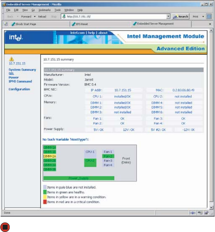
52 www.gateway.com
Chapter 3: Managing and Maintaining Your Server
3The web server displays the System Summary page after the user is authenticated.
Using the Embedded Web Server scripting interface
The Embedded Web Server can be accessed from a scripting language such as Perl or
JavaScript. The client script sends a GET or POST request to the server. The server will return
either an HTML web page or an XML response.
To return an HTML page, use one of the following formats:
http://hostname/ipmiPage?cmd=xx.xx.xx.xx.xx?onload=functionName
where xx.xx.xx.xx.xx is an IPMI 2.0 command in hexadecimal that is supported by
the platform.
8510702.book Page 52 Thursday, July 7, 2005 11:21 AM

53
www.gateway.com
Baseboard Management Controller (BMC)
http://hostname/webCmdPage?cmd=getSEL&first=num&last=num&onload=functio
nName
http://hostname/webCmdPage?cmd=clearSEL&onload=functionName
http://hostname/webCmdPage?cmd=changeVars&subcommand=value&onload=fun
ctionName
where subcommand is one of the following:
HealthyUpdateRate=num WarningUpdateRate=num
CriticalUpdateRate=num UsrUrl1=url (on-line help page URL)
UsrVal1=string (navigation bar label, the default is “help”)
UsrUrl2=url (the default is support.intel.com)
UsrVal2=string (navigation bar label, the default is “intel.com”)
3:Hostname=string (this only changes an internal web page variable)
3:Domainname=string (this only changes an internal web page variable)
The following syntax returns an XML response:
http://hostname/ipmiHex?cmd=xx.xx.xx.xx.xx
where xx represents one byte (two hex digits) of the IMPI 2.0 command (separate each
pair of hex digits with a period)
Web Server Responses
Command Response
ipmiPage Argument 1 = completion code
Argument 2 = the command that was executed
Argument 3 = the command response
webCmdPage Argument 1=an error code of 0 or 1 indicates no error
Argument 2=an error string associated with the code
Argument 3= the response data
ipmiHex <ipmiResp
completionCode=”
YY
”>
XX-XX-XX…
</ipmiResp>
(The completion code YY and the returned data bytes
XX are defined in the IPMI specification.)
8510702.book Page 53 Thursday, July 7, 2005 11:21 AM

54 www.gateway.com
Chapter 3: Managing and Maintaining Your Server
HTML Example
In this example, the client-side page loads the page returned by the Embedded Web Server
into a frame:
<FRAMESET …><FRAME …>
<A
HREF=http://222.222.39.10/ipmiPage?cmd=20.C0.64.07.00.00&onload=doOnLoad>
IPMI Command to check if web is enabled</A></FRAME>…</FRAMESET>
Perl Script Example
In the following example, a Perl script sends an HTTP GET to the server:
Use IO::Socket;
$sock = new IO::Socket::INET (PeerAddr => ‘222.222.39.10”,
PeerPort => 80,
Proto => ‘tcp’
);
die “Socket could not be created.” Unless $sock;
print $sock “GET /ipmiHex?cmd=20.C0.64.07.00.00 HTTP/1.0”
FRU/SDR Load utility
The FRU/SDR Load utility is a DOS-based utility that updates or changes the server
management subsystem’s product-level FRU (Field Replaceable Unit), and SDR (Sensor
Data Record) records, or displays the SMBIOS (System Management BIOS) non-volatile
storage components.
The FRU/SDR must be updated whenever you add additional hardware to your server
that must be monitored by the BMC (Baseboard Management Controller). This includes
adding a redundant power supply module, adding redundant hot-swap fans, or adding
an Intel Management Module (IMM). The FRU/SDR must also be updated whenever
you update the BIOS. Using the FRU/SDR Load Utility you can also:
■Determine the product configuration, based on instructions in a master
configuration file
■Display the FRU information
Important The default authentication is MD5 Digest authentication. This means
that command line scripting tools must be able to handle
authentication failures and respond to the server requests.
8510702.book Page 54 Thursday, July 7, 2005 11:21 AM

55
www.gateway.com
Baseboard Management Controller (BMC)
■Update the non-volatile storage device associated with the BMC that holds the SDR
and FRU information
■Generically handle FRU devices that might not be associated with the BMC
■View and direct results to the standard output device
Each time you update the FRU/SDR, we recommend that you check
support.gateway.com for the most current version of the utility. If you find a version
that is newer than the one included on the SCCD, download the newer version and
use it instead of the SCCD, following the instructions included with the new files. If
you are using the SCCD to update the FRU/SDR, use the following procedure.
To update the FRU/SDR:
1Download the current SUP CD image from www.support.gateway.com and create a
DOS-bootable SUP CD. For information on creating a SUP CD, see “Creating a
DOS-bootable System Update Package (SUP) CD” on page 42.
2Put the SUP CD in the CD drive and reboot from the CD.
3Open the FRU folder and click FRUSDR.EXE.
4When you are asked if you have an optional cooling kit installed, type Y if your system
has redundant fans installed or N if your system has only the basic fans installed.
5Exit the utility, remove the CD, then reboot your server.
The SEL Viewer utility
The SEL Viewer is a utility that lets you view the SEL (System Event Log) records, save SEL
entries to a file, and load SEL entries from a file. You can also reload SEL entries from a
server, view the properties of SEL entries, clear SEL entries from non-volatile memory, and
sort SEL records by various criteria. SEL entries can be viewed in either interpreted text
mode or hex mode.
Download the current SUP CD image from support.gateway.com for the most current
version of the utility.
To use the SEL viewer utility:
1Download the current SUP CD image from www.support.gateway.com and create a
DOS-bootable SUP CD. For information on creating a SUP CD, see “Creating a
DOS-bootable System Update Package (SUP) CD” on page 42.
2Put the SUP CD in the CD drive and reboot from the CD.
8510702.book Page 55 Thursday, July 7, 2005 11:21 AM
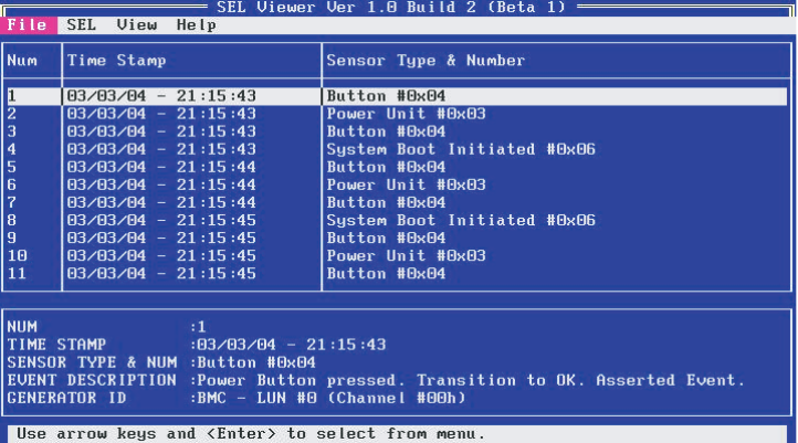
56 www.gateway.com
Chapter 3: Managing and Maintaining Your Server
3Open the DIAG folder and click SELVIEW.EXE. The SEL Viewer screen opens.
4The following menu items are available:
File - includes options for opening and saving system event log records, including:
Open - lets you open an existing SEL data file for viewing.
Save As - lets you save the SEL data to a file.
Exit - lets you exit the SEL Viewer utility.
SEL - includes options for reloading SEL entries from the server, including:
Reload - lets you reload SEL entries from the server.
Properties - lets you view the current condition of the SEL.
Clear - lets you delete all SEL entries from the non-volatile storage area of the server
and remove all entries from the main window table.
Sort By - lets you sort the SEL data by the selected field.
View - lets you choose between viewing options, which include hex/text, view/hide,
and screen resolution.
Help - provides SEL Viewer utility help, including a selection of help topics.
8510702.book Page 56 Thursday, July 7, 2005 11:21 AM

57
www.gateway.com
Baseboard Management Controller (BMC)
5Use the following keys to navigate the screens and menus:
■ENTER - to select an item from the menu bar
■TAB - to switch between the menu bar and the display panel
■F5 and F6 - to tab across the columns (in the text mode), right (F5) or left (F6)
■ARROW keys - to select individual menu items (from the menu bar) or entries (from
the display panel)
■PGDN and PGUP - to page through entries
■HOME and END - to go to the first or last entry, respectively
■INSERT - toggles insert and overwrite editing while in an edit box (indicated by INS
or OVR in the lower-right corner of the box)
■ESC - to move to the previous screen
6Exit the utility, remove the CD, then reboot your server.
8510702.book Page 57 Thursday, July 7, 2005 11:21 AM
58 www.gateway.com
Chapter 3: Managing and Maintaining Your Server
Using your System Companion CD
You can use your System Companion CD to:
■Install hardware drivers
■Install programs
■Access various utilities
■View server documentation
Instructions for using the CD are provided in Using Your System Companion CD, a booklet
which is provided with the CD.
8510702.book Page 58 Thursday, July 7, 2005 11:21 AM

59
www.gateway.com
Preparing for system recovery
Preparing for system recovery
If your system files are corrupted, you may not be able to start the server from the hard
drive. Startup diskettes are diskettes that let you start the server and attempt to fix the
problem. See your operating system’s documentation or online help for instructions on
creating startup diskettes.
Some operating systems also let you create an emergency repair diskette to back up critical
operating system files. See your operating system’s documentation or online help for
instructions on using an emergency repair diskette.
Recording the BIOS configuration
To help keep track of your custom changes to BIOS settings and to prepare for system
recovery, you should record your BIOS configuration after you have your server set up and
working.
To record your BIOS configuration:
1Print the appendix for BIOS Settings in this guide.
2Restart your server, then press any key when the Gateway logo screen appears during
startup. The System Options menu opens.
3Select BIOS Setup utility, then press ENTER. The BIOS Setup utility opens.
4Record the BIOS settings on your printout.
8510702.book Page 59 Thursday, July 7, 2005 11:21 AM
60 www.gateway.com
Chapter 3: Managing and Maintaining Your Server
Caring for your server
To extend the life of your server:
■Be careful not to bump or drop your server.
■When transporting your server, we recommend that you put it in the original
packaging materials.
■Keep your server and magnetic media away from equipment that generates magnetic
fields.
■Avoid subjecting your server to extreme temperatures. Do not expose your server to
heating ducts or other heat-generating objects. Damage caused by extreme
temperatures is not covered by your warranty. As a general rule, your server is safest
at temperatures that are comfortable for you.
■Keep all liquids away from your server. When spilled onto server components, almost
any liquid can result in extremely expensive repairs that are not covered under your
warranty.
■Avoid dusty or dirty work environments. Dust and dirt can clog the internal
mechanisms and can cause the server to overheat.
Cleaning your server
Keeping your server clean and the vents free from dust helps keep your server performing
at its best. Your server cleaning kit could include:
■A soft, lint-free cloth
■Glass cleaner
■An aerosol can of air with a narrow, straw-like extension
■Isopropyl alcohol
■Cotton swabs
■A tape drive cleaning cartridge (if a tape drive is installed)
■A CD or DVD drive cleaning kit
8510702.book Page 60 Thursday, July 7, 2005 11:21 AM

61
www.gateway.com
Caring for your server
Cleaning tips
■Always turn off your server and other peripheral devices before cleaning any
components.
■Use a damp, lint-free cloth to clean your server and other parts of your server system.
Do not use abrasive or solvent cleaners because they can damage the finish on
components.
■Keep the cooling vents free of dust. With your server turned off and unplugged, brush
the dust away from the vents with a damp cloth, but be careful not to drip any water
into the vents.
Cleaning the keyboard
You should clean the keyboard occasionally by using an aerosol can of air with a narrow,
straw-like extension to remove dust and lint trapped under the keys.
If you spill liquid on the keyboard, turn off your server and turn the keyboard upside down
to let the liquid drain. Let the keyboard dry completely before trying to use it again. If
the keyboard does not work after it dries, you may need to replace it. Keyboard damage
resulting from spilled liquids is not covered by your warranty.
Cleaning the screen
If your computer screen is a flat panel display, use only a damp, soft cloth to clean it.
Never spray water directly onto the screen.
- OR -
If your computer screen is not a flat panel display, use a soft cloth dampened with glass
cleaner to clean the screen. Never spray cleaner directly onto the screen.
Cleaning the tape drive
If you use a tape drive to back up your files, regular maintenance will lengthen the life
of the drive. To maintain the drive’s reliability:
■Clean the drive monthly with the cleaning cartridge included with the drive.
■Remove the tape from the drive whenever the drive is not in use.
Warning
When you shut down your server, the power turns off, but some
electrical current still flows through your server. To avoid possible
injury from electrical shock, unplug the power cords and all other
cables connected to the server.
Caution
The computer screen is made of specially coated glass and can be
scratched or damaged by abrasive or ammonia-based glass cleaners.
8510702.book Page 61 Thursday, July 7, 2005 11:21 AM

Chapter 4
63
Installing Components
• Opening and closing the server case
• Installing and replacing major components
You must open your server case to install
components. If you are not comfortable with these
procedures, get help from a more experienced
computer user or computer service technician, or
contact Gateway Customer Care.
8510702.book Page 63 Thursday, July 7, 2005 11:21 AM

64 www.gateway.com
Chapter 4: Installing Components
Preparing to install components
Selecting a place to work
Work on your server in an area that:
■Is clean (avoid dusty areas)
■Is a low-static environment (avoid carpeted areas)
■Has a stable surface on which to set your server
■Has enough room to place all of your server parts
■Is near a grounded outlet so you can test your server after installation
■Is near a telephone (in case you need help from Gateway Customer Care). The
telephone must be directly connected to a telephone jack and cannot be connected
to your server.
Gathering the tools you need
Some tools and supplies that you may need to work on your server are:
■A notebook to take notes
■A Phillips screwdriver
■A small flat-blade screwdriver
■Small containers to store various types of screws
■A grounding wrist strap (available at most electronic stores)
Torque settings
Screws securing specific components in this server require tightening to specific torque
values.
Component Torque
To p c ove r 0 . 9 0 N-m ( 8 i n- l b. )
Processor heat sink 0.67 N-m (6 in-lb.)
Hard drive carrier 0.90 N-m (8 in-lb.)
Front panel I/O board 0.90 N-m (8 in-lb.)
8510702.book Page 64 Thursday, July 7, 2005 11:21 AM

65
www.gateway.com
Preventing static electricity discharge
Preventing static electricity discharge
The components inside your server are extremely sensitive to static electricity, also known
as electrostatic discharge (ESD).
Before working with server components, follow these guidelines:
■Turn off the server by pressing and holding the power button on the front of the server
for several seconds, then unplug the power cords and all other cables.
■Press the power button to drain any residual power from the server.
■Wear a grounding wrist strap (available at most electronics stores) and attach it to a
bare metal part of the server. You can also touch a bare metal surface on the back of
the server with your finger.
■Avoid static-causing surfaces such as carpeted floors, plastic, and packing foam.
■Avoid working on the server when your work area is extremely humid.
■Remove components from their antistatic bags only when you are ready to use them.
Do not lay components on the outside of antistatic bags because only the inside of
the bags provide electrostatic protection.
■Always hold expansion cards by their edges or their metal mounting brackets. Avoid
touching the edge connectors and components on the cards. Never slide expansion
cards or components over any surface.
Warning
To avoid exposure to dangerous electrical voltages and moving parts,
turn off your server and unplug the power cords and modem cable
before opening the server case.
Caution
ESD can permanently damage electrostatic discharge-sensitive
components in the server. Prevent ESD damage by following ESD
guidelines every time you open the server case.
Warning
To prevent risk of electric shock, do not insert any object into the vent
holes of the power supply module.
8510702.book Page 65 Thursday, July 7, 2005 11:21 AM
66 www.gateway.com
Chapter 4: Installing Components
Opening the server case
Because the components inside your server are extremely sensitive to static electricity, make
sure that you follow the instructions at the beginning of this chapter to avoid static
electricity damage.
To open the server case:
1Follow the instructions in “Preventing static electricity discharge” on page 65.
2Turn off the server, then unplug the power cords and all other cables connected to
the server.
Warning
The total power requirement for this server exceeds the 240 VA
energy hazard limits that define an operator accessible area.
Therefore, only qualified technical individuals should access the
processor and non-hot-plug I/O areas of the server while the system
is energized. Power cords should be removed from the system before
accessing not-hot-plug areas.
Caution
For correct cooling and air flow, always reinstall the side panel and
the air duct (if included) before you turn on the server. Operating the
server without the cover in place can damage server components.
Warning
This server may have two power cords. To disconnect internal
AC power, you must unplug both power cords.
8510702.book Page 66 Thursday, July 7, 2005 11:21 AM
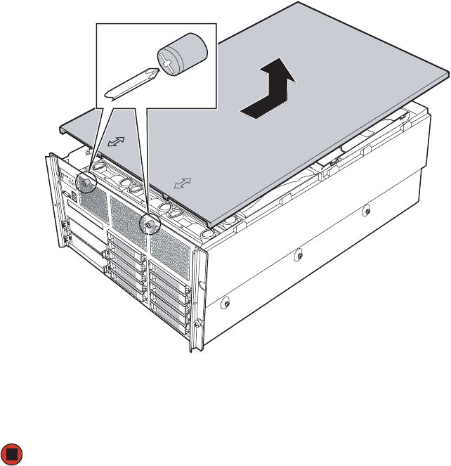
67
www.gateway.com
Removing and installing the processor air baffle
3Using a Phillips screwdriver, loosen the two captive screws on the faceplate securing
the top cover to the server case.
4When the screws are loose, slide the top cover toward the back of the case about ½
inch.
5Lift the top cover away from the server and place it out of the way.
Removing and installing the processor air
baffle
The processor air baffle must be removed to:
■Remove or install a processor thermal blank
■Remove or install a processor
■Remove or install a processor cache VRM converter
■Remove or install a CD or DVD drive
■Remove or install the system board
8510702.book Page 67 Thursday, July 7, 2005 11:21 AM
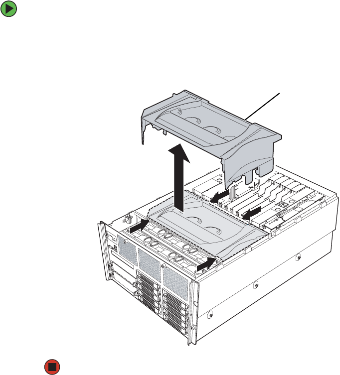
68 www.gateway.com
Chapter 4: Installing Components
■Change jumper settings
■Remove or install the front panel I/O board
To remove the processor air baffle:
1Follow the instructions in “Preventing static electricity discharge” on page 65.
2Follow the instructions in “Opening the server case” on page 66.
3Lift the processor air baffle from the chassis.
Processor air
baffle
8510702.book Page 68 Thursday, July 7, 2005 11:21 AM
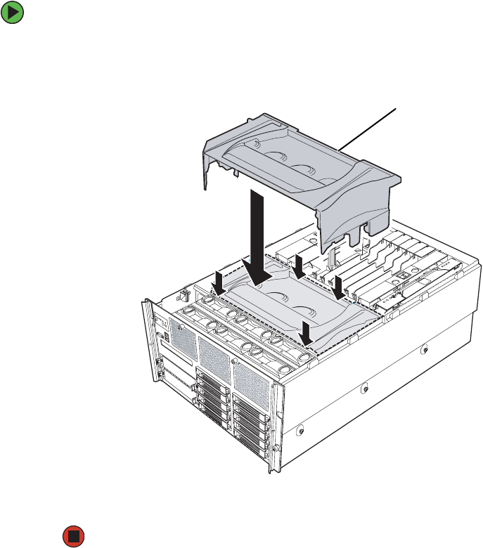
69
www.gateway.com
Removing and installing the center brace
To install the processor air baffle:
1Follow the instructions in “Preventing static electricity discharge” on page 65.
2Place the processor air baffle in the chassis.
3Follow the instructions in “Closing the server case” on page 72
Removing and installing the center brace
The center brace must be removed to:
■Remove or install a processor core VRM
■Remove or install the system board
■Remove or install the SCSI hot-swap backplane
Processor air
baffle
8510702.book Page 69 Thursday, July 7, 2005 11:21 AM
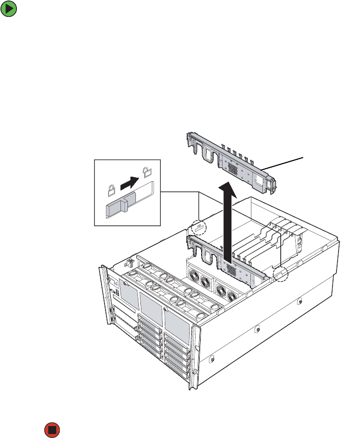
70 www.gateway.com
Chapter 4: Installing Components
To remove the center brace:
1Follow the instructions in “Preventing static electricity discharge” on page 65.
2Follow the instructions in “Opening the server case” on page 66.
3Remove the processor air baffle by following the instructions in “Removing and
installing the processor air baffle” on page 67.
4Move the two center brace locks (located on both sides of and behind the center brace)
toward the back of the case to unlock the center brace.
5Lift the center brace straight up, out of the case.
Center braceCenter brace lock
8510702.book Page 70 Thursday, July 7, 2005 11:21 AM
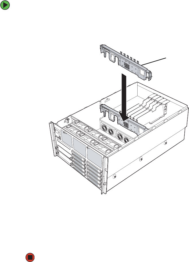
71
www.gateway.com
Removing and installing the center brace
To install the center brace:
1Align the center brace with the guides on both sides of the case and with the
full-length PCI expansion cards to the back, then lower the center brace into the case
until it is fully seated.
2Move the two center brace locks (located on both sides of and behind the center brace)
toward the front of the case to lock the center brace into place.
3Follow the instructions in “Removing and installing the processor air baffle” on
page 67.
4Follow the instructions in “Closing the server case” on page 72.
Center brace
8510702.book Page 71 Thursday, July 7, 2005 11:21 AM
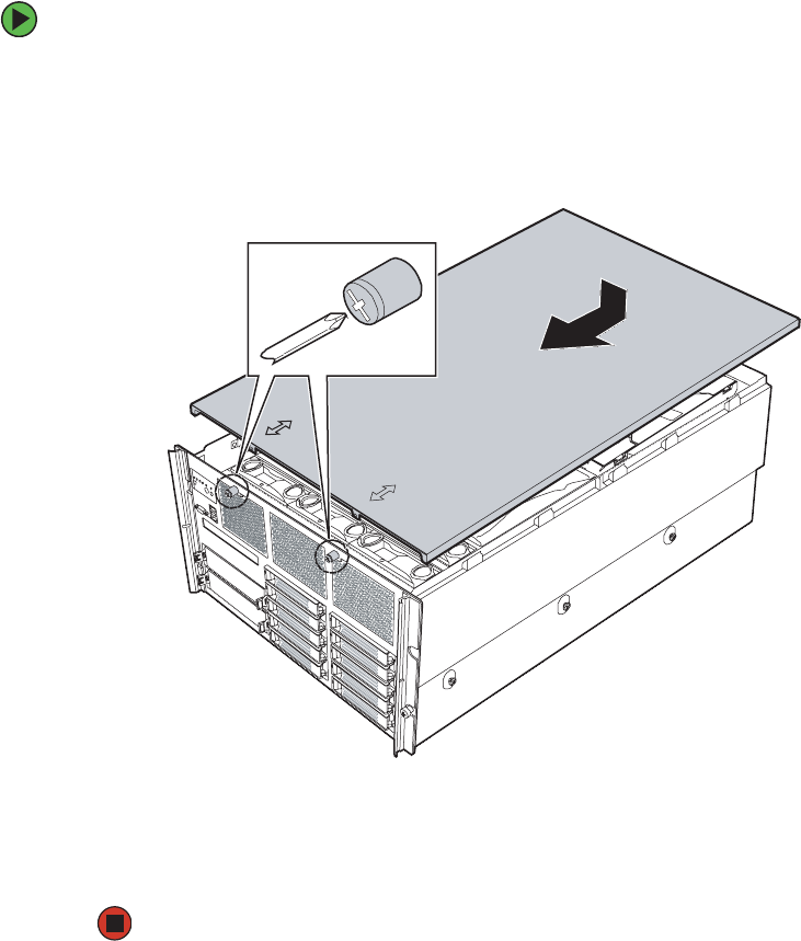
72 www.gateway.com
Chapter 4: Installing Components
Closing the server case
To close the server case:
1Make sure that all of the internal cables are arranged inside the case so they will not
be pinched when you close the case.
2Align the tabs on the top cover with the slots in the chassis, then slide the top cover
toward the front of the chassis until it meets the face plate.
3Secure the top cover by tightening the two captive screws in the face plate (see “Torque
settings” on page 64).
4Reconnect the power cords and all other cables.
8510702.book Page 72 Thursday, July 7, 2005 11:21 AM
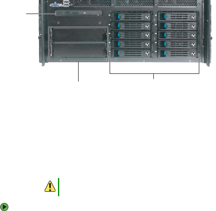
73
www.gateway.com
Installing drives
Installing drives
Your server’s basic configuration includes one CD (standard) or DVD (optional) drive. Your
server also has two additional 5.25-inch drive bays, which can accommodate two
half-height or one full height SCSI tape drive.
Your server can have as many as ten, hot-swap SCSI drives in hot-swap drive bays.
As you prepare to install drives, remember:
■Before you install a drive, see the drive’s documentation for information on
configuring the drive, setting drive jumpers, and attaching cables.
■You may need to configure the drives you install using the BIOS Setup utility.
■To open the BIOS Setup utility, press any key at startup to open the System Options
menu, then select the BIOS Setup utility and press ENTER. The BIOS Setup utility
opens.
Installing and removing the CD or DVD drive
To remove the CD or DVD drive:
1Follow the instructions in “Preventing static electricity discharge” on page 65.
Caution
CD, DVD, and tape drives are not hot-swappable, so the server must
be turned off and the AC power cords removed prior to installing,
removing, or servicing these devices.
5.25-inch
drive bays (2)
CD or
DVD drive
Hot-swap hard drive
bays (10)
8510702.book Page 73 Thursday, July 7, 2005 11:21 AM
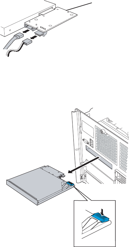
74 www.gateway.com
Chapter 4: Installing Components
2Follow the instructions in “Opening the server case” on page 66.
3Remove the processor air baffle by following the instructions in “Removing and
installing the processor air baffle” on page 67.
4Disconnect the SATA and power cables from the SATA-to-IDE converter board on the
back of the CD or DVD drive.
5Remove the front panel cable from the SCSI hot-swap backplane by following the
instructions in “Replacing the SCSI hot-swap backplane” on page 139.
6Press the blue release latch on the back of the CD/DVD drive carrier, then slide the
drive carrier assembly out the opening in the front panel.
S
ATA- t o- I DE
converter board
8510702.book Page 74 Thursday, July 7, 2005 11:21 AM
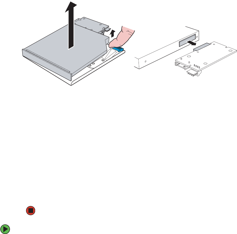
75
www.gateway.com
Installing drives
7Lift up on the right-rear corner of the CD or DVD drive to disengage it from the drive
carrier, then remove it from the carrier.
8Disconnect the SATA-to-IDE converter board from the back of the drive, then place
the drive in an anti-static bag for storage.
9Slide the empty drive carrier back into the server.
- OR -
If you are replacing the drive, see “To install a CD or DVD drive:” on page 75, and
begin at Step 6.
10 Reconnect the front panel cable to the SCSI hot-swap backplane by following the
instructions in “Replacing the SCSI hot-swap backplane” on page 139.
11 Replace the processor air baffle by following the instructions in “Removing and
installing the processor air baffle” on page 67.
12 Follow the instructions in “Closing the server case” on page 72.
To install a CD or DVD drive:
1Follow the instructions in “Preventing static electricity discharge” on page 65.
2Follow the instructions in “Opening the server case” on page 66.
3Remove the processor air baffle by following the instructions in “Removing and
installing the processor air baffle” on page 67.
4Remove the front panel cable from the SCSI hot-swap backplane by following the
instructions in “Replacing the SCSI hot-swap backplane” on page 139.
8510702.book Page 75 Thursday, July 7, 2005 11:21 AM
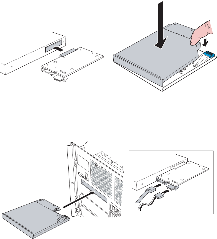
76 www.gateway.com
Chapter 4: Installing Components
5Remove the CD/DVD drive carrier from the server by following the instructions in
“To remove the CD or DVD drive:” on page 73.
6Remove the new drive from its packaging and place it, component-side down, on an
ESD-protected work surface.
7Record the model and serial numbers as necessary.
8Attach the SATA-to-IDE converter board to the connector on the back of the drive.
9Place the left side of the drive into the drive carrier, then press down on the right
side until it is firmly seated.
10 Insert the drive carrier assembly into the front panel of the server until it clicks into
place.
11 Plug the SATA and power cables into the SATA-to-IDE converter board on the back
of the drive.
8510702.book Page 76 Thursday, July 7, 2005 11:21 AM

77
www.gateway.com
Installing drives
12 Reconnect the front panel cable to the SCSI hot-swap backplane by following the
instructions in “Replacing the SCSI hot-swap backplane” on page 139.
13 Replace the processor air baffle by following the instructions in “Removing and
installing the processor air baffle” on page 67.
14 Follow the instructions in “Closing the server case” on page 72.
Installing a fixed, removable-media drive in a 5.25-inch
drive bay
Use these instructions to install or replace a CD, DVD, or tape drive.
To install a 5.25-inch drive:
1Follow the instructions in “Preventing static electricity discharge” on page 65.
2Follow the instructions in “Opening the server case” on page 66.
3If you are replacing a drive, go to Step 5.
- OR -
Caution
Cooling and EMI constraints do not permit the installation of an IDE
hard drive in either of the 5.25-inch drive bays.
Caution
CD, DVD, and tape drives are not hot-swappable, so the server must
be turned off and the AC power cords removed prior to installing,
removing, or servicing these devices.
Important Two half-height or one full-height SCSI tape drive can be installed in
the available 5.25-inch drive bays.
8510702.book Page 77 Thursday, July 7, 2005 11:21 AM
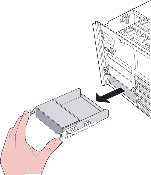
78 www.gateway.com
Chapter 4: Installing Components
If you are adding a new drive to an available 5.25-inch device bay, remove the filler
panel assembly from the bay by pressing and holding the two locking clips inward,
then pulling the filler panel assembly out of the bay.
4Remove the drive rails from the filler panel assembly by removing the screws holding
the rails to the assembly, then go to Step 8.
5Disconnect the old drive’s cables from the back of the drive.
6Press the rail tabs against the drive, then pull the drive out of the bay.
7Remove the screws that hold the drive rails to the old drive, then remove the rails.
8Attach the rails to the new drive with the screws you just removed.
9Set any jumpers on the new drive. See the drive’s documentation for further
instructions.
10 Connect the power and data cables to the drive. For the location of the connectors
on the system board, see “System board” on page 5. For additional drive information,
see the drive’s documentation.
8510702.book Page 78 Thursday, July 7, 2005 11:21 AM
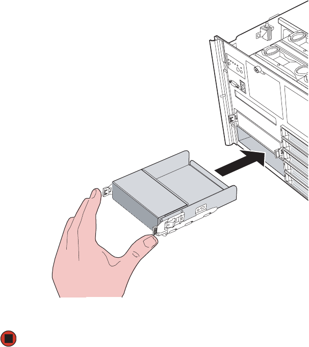

80 www.gateway.com
Chapter 4: Installing Components
Installing a hot-swap hard drive
Use this procedure to add or replace hard drives in a hot-swap drive bay. Your server has
room for as many as ten hot-swap drive carriers and each drive carrier holds a 1-inch high,
Ultra320 SCSI, SCA-type hard drive, running at 15,000 RPM or slower.
The SCSI backplane (and hot-swap drive bays) support only LVD (Low Voltage Differential)
drives. However, the external SCSI connector (on the back of the server) also supports SE
(Single Ended) drives. (You can purchase additional drives through your Gateway sales
representative.
Determining drive status
Each drive carrier has an LED on the front of the server which shows the drive status.
To install a hot-swap hard drive:
1If you are installing a new drive, select an empty drive carrier from the hot-swap drive
bays.
Important Gateway tests and verifies the operation and compatibility of the
drives it sells. Especially in a hot-swap or mission-critical
environment, additional or replacement drives must conform to
Gateway standards.
LED condition Drive status
Green flashing Hard drive is active
Orange and
green flashing
alternately
Hard drive is powered on and is rebuilding RAID, or is
powered on and has a fault condition.
Orange flashing Hard drive is not powered on and has a fault condition.
Unlit No hard drive is installed in the carrier or a drive is
installed but is inactive.
Important The numbers on the left side of the hot-swap bays identify the SCSI
ID and SCSI channel (A or B) of each drive. Install the drives, starting
with drive A0, then B0, then A1, B1, A2, B2, and so on.
8510702.book Page 80 Thursday, July 7, 2005 11:21 AM
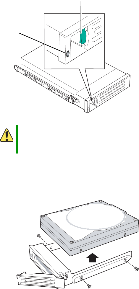
81
www.gateway.com
Installing drives
2If you are replacing a failed drive, determine which drive has failed by checking the
drive status LEDs on the front of the drive carriers.
3Remove the drive carrier by pressing the drive latch and pulling the drive tray lever
to the right (away from the server), then pull the tray straight out of the server.
4If you are replacing a hard drive, remove the four screws that secure the hard drive
to the drive carrier, then remove the drive from the carrier.
Caution
Before you remove a failed drive, use the appropriate software and
utilities installed on the server to stop all activity on the failed drive.
Instructions for using the software are provided by the software
manufacturer. Failure to do so may destroy the data on the drive.
Drive status
LED
Drive latch
8510702.book Page 81 Thursday, July 7, 2005 11:21 AM
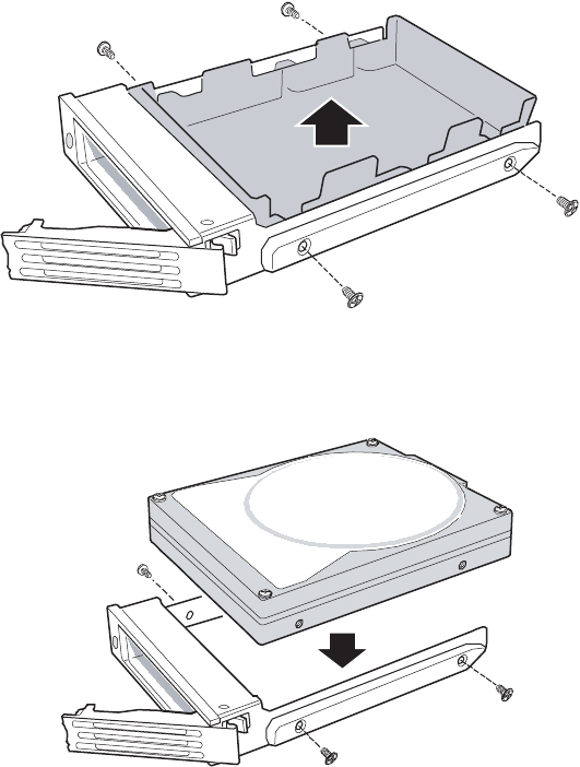
82 www.gateway.com
Chapter 4: Installing Components
- OR -
If you are adding a new drive, first remove the four screws securing the plastic
retention device into the drive carrier, then remove the plastic retention device from
the drive carrier.
5Line up the screw holes in the new drive with the holes in the side of the drive carrier,
then secure the drive to the carrier with the four screws you removed in Step 4.
8510702.book Page 82 Thursday, July 7, 2005 11:21 AM
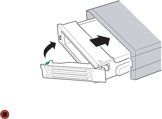
83
www.gateway.com
Installing drives
6Make sure that the drive carrier’s release lever is open, then use the lever to slide the
new drive into the empty hot-swap bay until it docks in the chassis.
7Close the drive’s release lever by rotating the lever to the left to latch the drive carrier
into position.
8510702.book Page 83 Thursday, July 7, 2005 11:21 AM
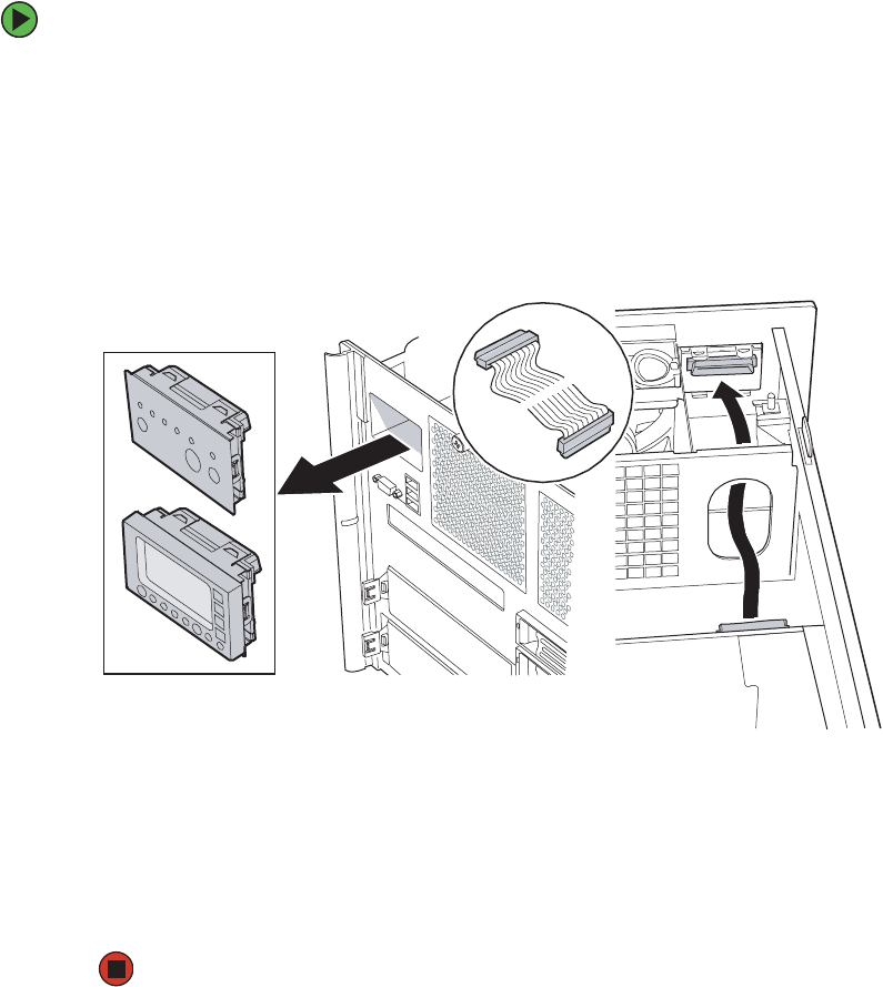
84 www.gateway.com
Chapter 4: Installing Components
Removing and installing the control
panel
Removal and installation of the control panel and front panel board is the same, regardless
of whether your server is equipped with the standard control panel or the optional local
control panel (LCP).
To remove and install the control panel:
1Follow the instructions in “Preventing static electricity discharge” on page 65.
2Follow the instructions in “Opening the server case” on page 66.
3Disconnect the front panel cable from the front panel board attached to the back of
the control panel.
4Push the control panel out through the face plate of the server and store it in an
anti-static bag.
5Push the new control panel into the control panel opening in face plate of the server
until it is securely seated.
6Connect the front panel cable to the back of the front panel board located on the
back of the control panel.
7Follow the instructions in “Closing the server case” on page 72.
8510702.book Page 84 Thursday, July 7, 2005 11:21 AM

85
www.gateway.com
Memory
Memory
Your server has four PCI ×16 connectors on the system board for memory boards. Each
memory board has sockets for four DIMMs and supports two DDR2 channels (with two
DIMMs per channel). Memory boards support both single-rank and double-rank, registered
DIMMs. One to four memory boards can be installed.
Installing and removing memory boards
Memory boards can be configured in either redundant or non-redundant configurations.
Memory boards configured using RAID or mirroring are considered redundant. If a memory
or memory board fault occurs on a memory board that is redundantly configured, the
board containing the fault can be removed, and the board or DIMM replaced, while the
system is on. Memory boards that are not redundantly configured (including boards that
are configured with spare memory) must not be removed while the system is on.
The following memory board replacement options are available to this server:
■Memory hot replace - A failed memory board can be replaced while the system is
on only if its in a RAID or Mirrored configuration. The system will test, initialize, and
rebuild the data on the memory board, then include the board in the system memory
configuration. The replacement is transparent to the operating system. For additional
information, see “Hot removal and insertion of memory boards” on page 87.
■Memory hot add - You can increase the memory capacity of the system while the
operating system is active only if its in a RAID or Mirrored configuration. Memory
can be removed and replaced on only one memory board at a time and the memory
board must be replaced before attempting to remove another board. If your server is
configured for Maximum Compatibility, a new memory board can be added to an
empty slot. The system will test and initialize the new memory, then inform the
operating system. For additional information, see “Hot removal and insertion of
memory boards” on page 87.
Caution
Do not attempt to hot replace or hot add a memory board in a
non-redundant configuration. If your server is not configured for
Maximum Compatibility, Memory RAID, or Memory Mirroring in the
BIOS setup utility, you must turn off your server before removing or
installing any memory board or DIMMs.
Caution
Memory board air baffles are installed in memory slots without
memory boards. These air baffles must be removed to install a
memory board. To maintain the correct airflow in your server and
prevent overheating, if you intend to remove a memory board from
your server and not replace it immediately, install a memory board
air baffle in the empty slot.
8510702.book Page 85 Thursday, July 7, 2005 11:21 AM
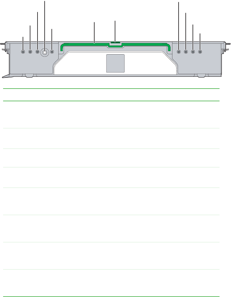
86 www.gateway.com
Chapter 4: Installing Components
■Cold memory add/replacement - If your server is not in a RAID or Mirrored
configuration, memory boards can only be added or replaced when the system is
turned off. For additional information, see “Cold removal and installation of memory
boards” on page 89.
Indicator LED Description
Mirror Configuration
LED (Green)
LED on - The server is in Memory Mirror configuration. This
memory board mirrors another memory board in the system.
LED off - The server in not configured for Memory Mirror.
RAID Configuration
LED (Green)
LED on - The server is in RAID memory configuration.
LED off - The server is not in a RAID memory configuration.
Hot Plug Attention
LED (Orange)
LED flashing - This memory board is in a hot-plug event.
Power LED (Green) LED on - Power is detected and the memory board is on.
LED off - Power is not detected and the board is off.
DIMM 1B Status LED
(Orange)
LED on - Error for DIMM slot 1B (J3A1). The indicated DIMM
is in a fault condition and needs to be replaced.
LED off - The indicated DIMM is functioning correctly.
DIMM 1A Status LED
(Orange)
LED on - Error for DIMM slot 1A (J3A2). The indicated DIMM
is in a fault condition and needs to be replaced.
LED off - The indicated DIMM is functioning correctly.
DIMM 2B Status LED
(Orange)
LED on - Error for DIMM slot 2B (J3B1). The indicated DIMM
is in a fault condition and needs to be replaced.
LED off - The indicated DIMM is functioning correctly.
DIMM 2A Status LED
(Orange)
LED on - Error for DIMM slot 2A (J3B2). The indicated DIMM
is in a fault condition and needs to be replaced.
LED off - The indicated DIMM is functioning correctly.
Mirror configuration
LED
DIMM 2B status LED
DIMM 2A status LED
DIMM 1A status LED
DIMM 1B status LED
RAID configuration LED
Hot Plug Attention LED
Power button
Power LED
Handle Latch
8510702.book Page 86 Thursday, July 7, 2005 11:21 AM
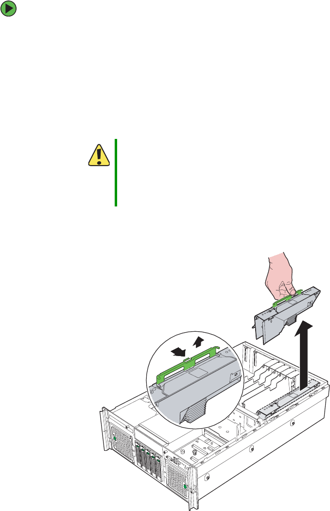
87
www.gateway.com
Memory
Hot removal and insertion of memory boards
To replace a memory board or add memory while the system is on:
1Follow the instructions in “Preventing static electricity discharge” on page 65.
2Follow the instructions in “Opening the server case” on page 66, but do not turn off
the server.
3Press the power button on the memory board you intend to replace. The orange Hot
Plug Attention LED begins to flash.
4When the orange Hot Plug Attention LED turns off, make sure the Power LED for the
memory board is also off.
5Press the latch on the memory board handle and lift the handle to unlock the memory
board.
Caution
Do not attempt to remove the memory board while the Hot Plug
Attention LED is on or flashing. If the Hot Plug Attention LED does
not turn off, your configuration may not support hot-plug memory
board replacement. For instructions on cold replacement of memory
boards, see “Cold removal and installation of memory boards” on
page 89.
8510702.book Page 87 Thursday, July 7, 2005 11:21 AM
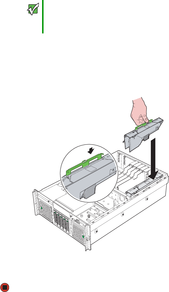
88 www.gateway.com
Chapter 4: Installing Components
6Pull up on the memory board handle and lift the memory board from the server.
7Install or replace DIMMs on the memory board by following the instructions in
“Installing and removing DIMMs” on page 91.
8Make sure the handle on the memory board is in the open/up position, then align
the ends of memory board with the card guides at each end and insert the memory
board into the memory board slot.
9Push the memory board handle down into the locked position.
10 Follow the instructions in “Closing the server case” on page 72.
Important Unlocking and lifting the memory board handle, then pulling the
handle to remove the memory board immediately disables power to
the memory slot. If the server is not correctly configured for hot
memory board replacement this will cause the operating system to
crash, but will not electrically damage the system.
8510702.book Page 88 Thursday, July 7, 2005 11:21 AM
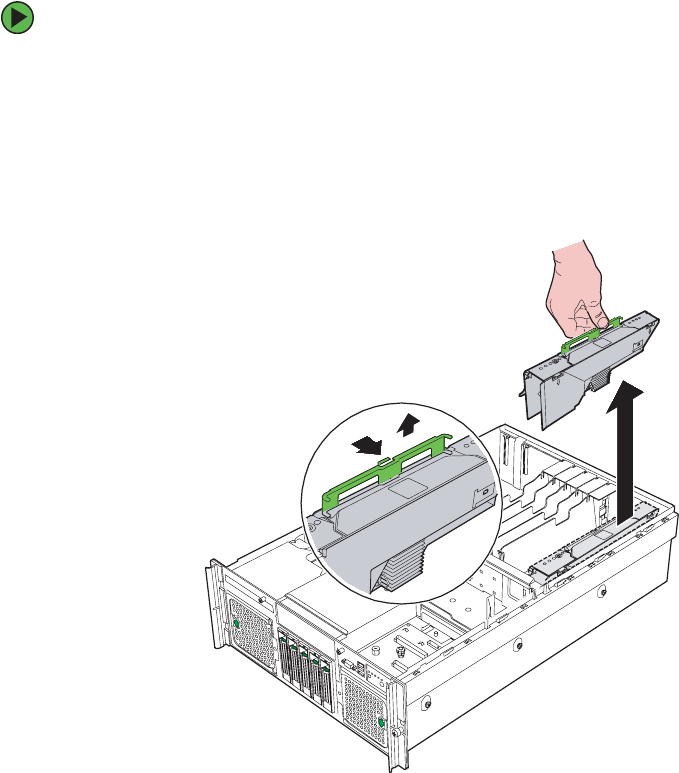
89
www.gateway.com
Memory
Cold removal and installation of memory boards
To remove/replace a memory board while the system is off:
1Follow the instructions in “Preventing static electricity discharge” on page 65.
2Follow the instructions in “Opening the server case” on page 66.
3Press the latch on the memory board handle and lift the handle to unlock the memory
board.
4Pull up on the memory board handle and lift the memory board from the server.
5Install or replace DIMMs on the memory board by following the instructions in
“Installing and removing DIMMs” on page 91.
- OR -
Install a memory board air baffle into the open memory slot on the system board,
the proceed to Step 8.
6Make sure the handle on the memory board is in the open/up position, then align
the ends of memory board with the card guides at each end and insert the memory
board into the memory board slot.
8510702.book Page 89 Thursday, July 7, 2005 11:21 AM
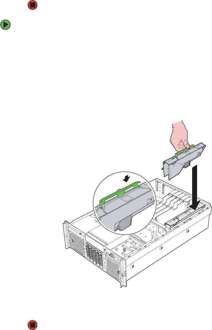
90 www.gateway.com
Chapter 4: Installing Components
7Push the memory board handle down into the locked position.
8Follow the instructions in “Closing the server case” on page 72.
To add a memory board while the system is off:
1Follow the instructions in “Preventing static electricity discharge” on page 65.
2Follow the instructions in “Opening the server case” on page 66.
3Remove the memory board air baffle from the memory slot you intend to use.
4Install DIMMs on the new memory board by following the instructions in “Installing
and removing DIMMs” on page 91.
5Make sure the handle on the memory board is in the open/up position, then align
the ends of memory board with the card guides at each end and insert the memory
board into the memory board slot.
6Push the memory board handle down into the locked position.
7Follow the instructions in “Closing the server case” on page 72.
8510702.book Page 90 Thursday, July 7, 2005 11:21 AM

91
www.gateway.com
Memory
Installing and removing DIMMs
When you change the amount of memory in this server, memory must be added to, or
removed from memory boards (see “Installing and removing memory boards” on page 85).
When you upgrade your server memory, make sure that you install the correct type of
memory. Your server supports from 512 MB to 64 GB total memory. Supported DIMM sizes
include 256MB, 512MB, 1GB, 2GB and 4GB.
Memory boards must be populated using the following guidelines:
■Each memory board has two DIMM banks (a pair of DIMM sockets), and a bank may
consist of one or two ranks (a pair of single-sided DIMMs or a pair of double-sided
DIMMs, respectively).
■Bank 1 - DIMM sockets 1A and 1B
■Bank 2 - DIMM sockets 2A and 2B
■Within a memory bank, DIMMs must be installed in identical pairs.
■Same size
■Same manufacturer
■Same number of devices on the DIMMs
■DIMM banks must be populated in order on each memory board, starting with Bank
1 (sockets 1A and 1B).
■Dual rank DIMMs must be populated before single rank DIMMs.
■For best memory performance, use identical DIMMs on each memory board.
■Use only DDR2 DIMMs. No other DIMMs will fit into the DIMM sockets.
■Use only DIMMs with gold-plated edge connectors.
■The maximum DIMM height is 1.75-inches (4.445 cm). Do not install DIMMs that
exceed this height.
Caution
Memory modules must be identical in each bank. Use only
DDR2-400 MHz, ECC registered, 240-pin DIMM memory modules in
256 MB, 512 MB, 1 GB, 2 GB, or 4 GB sizes. Do not use unbuffered
DIMMs.
On each memory board, memory modules must be installed in pairs,
to completely fill each bank, and the banks must be filled in order. If
you have memory installed incorrectly, your server will not start up.
8510702.book Page 91 Thursday, July 7, 2005 11:21 AM
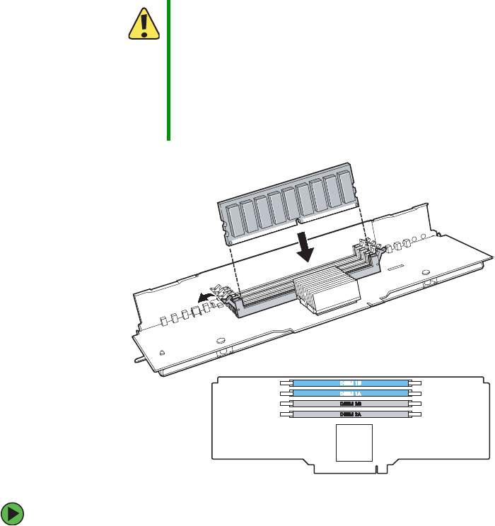
92 www.gateway.com
Chapter 4: Installing Components
To install or replace DIMMs:
1Follow the instructions in “Preventing static electricity discharge” on page 65.
2Follow the instructions in “Opening the server case” on page 66.
3Remove the memory board or memory board air baffle from the system board by
following the instructions in “Installing and removing memory boards” on page 85.
Caution
Attempts to force non-DDR2 DIMMs into a socket on the memory
board will result in damage to the DIMM, damage to the socket, or
damage to both.
Use extreme care when installing DIMMs. Applying too much
pressure can damage the DIMM socket or the DIMM. DIMMs are
keyed and can only be installed one way.
Hold DIMMs by the edges. Do not touch the gold connectors or the
components.
8510702.book Page 92 Thursday, July 7, 2005 11:21 AM
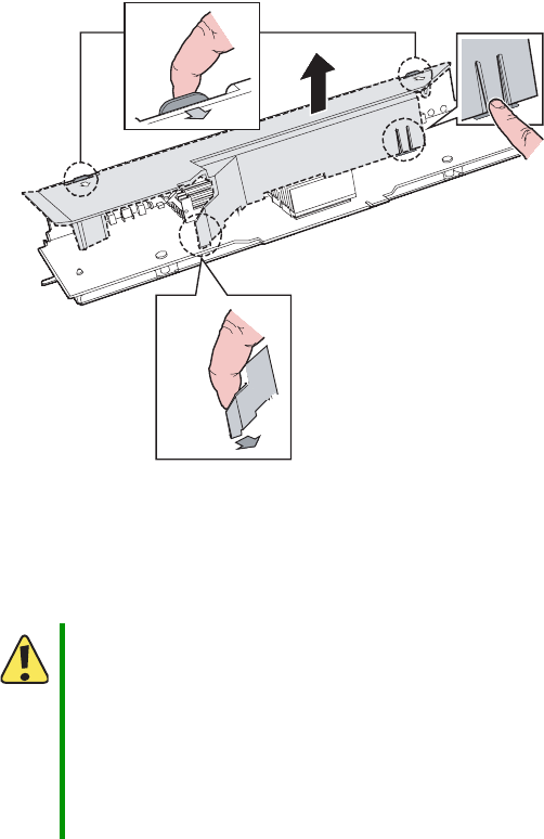
93
www.gateway.com
Memory
4Remove the DIMM cover from the memory board.
aPull out the DIMM cover latch.
bPress the DIMM cover tabs.
cPress the DIMM cover retainer tab.
dLift the DIMM cover off the memory board.
5Pull the plastic tabs away from the sides of the memory sockets you intend to use.
If you are removing or replacing a DIMM, remove the DIMM and place it in an
anti-static bag.
Caution
Attempts to force non-DDR2 DIMMs into a socket on the memory
board will result in damage to the DIMM, damage to the socket, or
damage to both.
Use extreme care when installing DIMMs. Applying too much
pressure can damage the DIMM socket or the DIMM. DIMMs are
keyed and can only be installed one way.
Hold DIMMs by the edges. Do not touch the gold connectors or the
components.
8510702.book Page 93 Thursday, July 7, 2005 11:21 AM
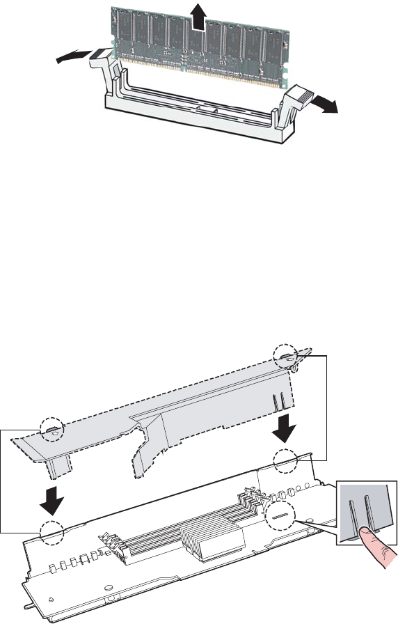
94 www.gateway.com
Chapter 4: Installing Components
6Align the notch on the new module with the key in the memory module socket and
press the module firmly into the socket. The tabs on the sides of the memory socket
should secure the memory module automatically.
7Reinstall the DIMM cover.
aAlign the DIMM cover tabs with the top of the memory board.
bPress in the DIMM cover retainer tab.
cPress down on the DIMM cover until it clicks into place.
8Install the memory board by following the instructions in “Installing and removing
memory boards” on page 85.
9Follow the instructions in “Closing the server case” on page 72.
8510702.book Page 94 Thursday, July 7, 2005 11:21 AM

95
www.gateway.com
Memory
10 Restart your server and open the BIOS Setup utility. Verify the System Memory listed
in the Main menu. When you exit the BIOS Setup utility, make sure that the operating
system loads completely.
11 Follow the instructions in “FRU/SDR Load utility” on page 54.
Configuring memory options
Memory sparing
The chipset on the system board in the server supports memory sparing, which can provide
a way to prevent data loss in case of DIMM failure. If a DIMM failure does occur, a DIMM
fault LED on the memory board will light orange to indicate the failed DIMM.
Using memory sparing, one rank (a pair of single-sided DIMMS or one double-sided DIMM)
on each memory board is used as a memory spare for another rank on the same memory
board. If a DIMM begins to fail, the contents of the failing DIMM is copied to the spare
DIMM rank on the same memory board. When all of the data is copied, the primary rank
is automatically removed from service. One DIMM rank is always maintained in reserve
and cannot be used by the operating system.
To configure memory sparing:
1During server startup, access the System Options Menu. (See “Starting your server”
on page 16.)
2Press the up and down arrow keys to select BIOS Setup Utility from the System Options
Menu, then press ENTER. The BIOS Setup utility opens.
3Press the up and down arrow keys to select Memory, then press ENTER. The Memory
configuration menu opens.
4Press the up and down arrow keys to select Configure System RAS and Performance, then
press ENTER. The Configure System RAS and Performance screen opens.
5Set the Desired Memory Configuration to either Max Performance or Maximum
Compatibility.
6Select View Configuration Details.
■Make sure that Configuration Possible indicates Yes. If it indicates No, you may
need to install more memory to meet the requirements of the selected
configuration.
■Make sure that Sparing indicates Yes.
8510702.book Page 95 Thursday, July 7, 2005 11:21 AM

96 www.gateway.com
Chapter 4: Installing Components
7Return to the Memory configuration menu and set the Sparing Threshold between 1
and 15.
8Select View and Configure Memory Board x (where x is the memory board that is being
configured).
■Make sure that the Board Status is Healthy.
9Set the Reserve Rank for Spare to Enabled.
10 Press F10 to save your changes and exit.
11 Press Y to confirm and the server reboots with the changes.
Memory RAID
If the server contains four memory boards with equal memory capacity, the system can
be configured for Memory RAID. Using memory RAID, one memory board in the server
is held in reserve for memory parity information. This reduces the overall available memory
of the system to 75% of the total installed memory.
Hot removal of memory boards is supported when the server is configured for memory
RAID. The RAID LED on the memory board indicates that the board is in a RAID
configuration.
To configure memory RAID:
1During server startup, access the System Options Menu. (See “Starting your server”
on page 16.)
2Press the up and down arrow keys to select BIOS Setup Utility from the System Options
Menu, then press ENTER. The BIOS Setup utility opens.
3Press the up and down arrow keys to select Memory, then press ENTER. The Memory
configuration menu opens.
4Press the up and down arrow keys to select Configure System RAS and Performance, then
press ENTER. The Configure System RAS and Performance screen opens.
5Set the Desired Memory Configuration to RAID.
6Select View Configuration Details.
■Make sure that Configuration Possible indicates Yes. If it indicates No, you may
need to install more memory to meet the requirements of the selected
configuration.
8510702.book Page 96 Thursday, July 7, 2005 11:21 AM

97
www.gateway.com
Memory
7Press F10 to save your changes and exit.
8Press Y to confirm and the server reboots with the changes.
Memory mirroring
If the server contains two or four memory boards with equal memory capacity, the system
can be configured for memory mirroring. Using memory mirroring, the memory on one
memory board in the server is mirrored by a second memory board. This reduces the overall
available memory of the system to 50% of the total installed memory.
When a memory board or DIMM fault is detected on the primary memory board (in a
mirrored pair), the secondary memory board takes over as primary until the failing board
is replaced.
Hot removal of memory boards is supported when the server is configured for memory
mirroring. The Memory Mirror LED on the memory board indicates that the board is in
a memory mirrored configuration.
To configure memory mirroring:
1During server startup, access the System Options Menu. (See “Starting your server”
on page 16.)
2Press the up and down arrow keys to select BIOS Setup Utility from the System Options
Menu, then press ENTER. The BIOS Setup utility opens.
3Press the up and down arrow keys to select Memory, then press ENTER. The Memory
configuration menu opens.
4Press the up and down arrow keys to select Configure System RAS and Performance, then
press ENTER. The Configure System RAS and Performance screen opens.
5Set the Desired Memory Configuration to Mirror.
6Select View Configuration Details.
■Make sure that Configuration Possible indicates Yes. If it indicates No, you may
need to install more memory to meet the requirements of the selected
configuration.
7Press F10 to save your changes and exit.
8Press Y to confirm and the server reboots with the changes.
8510702.book Page 97 Thursday, July 7, 2005 11:21 AM
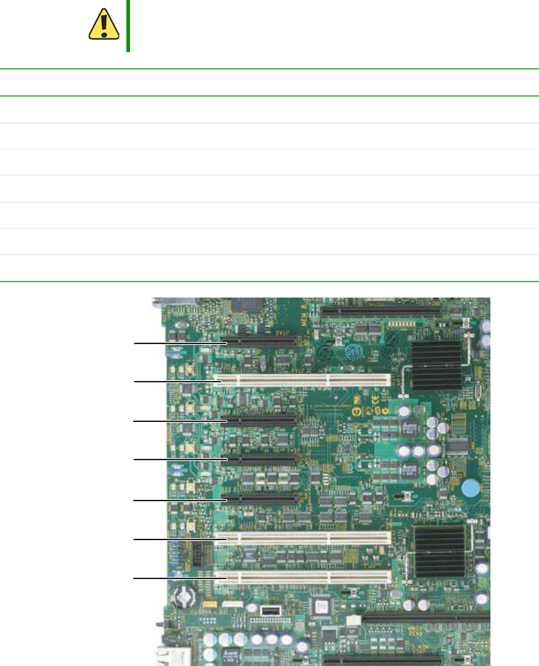
98 www.gateway.com
Chapter 4: Installing Components
PCI expansion cards
Your server uses the PCI-X bus. Use the following chart to determine the PCI slot into
which you should install your expansion card.
Caution
Only PCI cards in slots 1 - 5 are hot-swappable. Do not attempt to
install or remove PCI cards in slots 6 or 7 without turning off your
server and disconnecting it from the AC power source.
PCI slot Description
1 PCI Express x8 - Hot-swap
2 PCI-X - Runs at 64-bit /133MHz - Hot-swap
3 PCI Express x4 - Hot-swap
4 PCI Express x4 - Hot-swap
5 PCI Express x4 - Hot-swap
6 PCI-X - Runs at 64-bit/100 MHz - Not hot-swappable
7 PCI-X - Runs at 64-bit/100 MHz - Not hot-swappable
PCI slot 3
PCI slot 4
PCI slot 5
PCI slot 7
PCI slot 6
PCI slot 2
PCI slot 1
8510702.book Page 98 Thursday, July 7, 2005 11:21 AM
99
www.gateway.com
PCI expansion cards
Hot installation or removal of PCI expansion cards
Adjacent to each of the five hot-swap PCI slots are power LEDs and attention LEDs. The
attention LEDs indicate the operational condition of the slot, and the power LEDs indicate
the power condition of the slot. There is also an Attention button, located by the green
arrow on the PCI divider label, which is used to initiate the sequence to hot-swap a card.
To remove a hot-swap PCI expansion card with operating system hot-plug interface:
1Follow the instructions in “Preventing static electricity discharge” on page 65.
2Follow the instructions in “Opening the server case” on page 66, but do not turn off
or unplug the server.
3With the Microsoft Windows operating system open, double-click the Unplug/Eject
icon in the taskbar to open the Unplug or Eject Hardware menu. The Unplug or Eject
Hardware menu opens.
Power LED
(Green)
Indicates
Off Power is off: All main rails have been removed from the
slot and the card can be inserted or removed.
On Power is on: The slot is powered on and the card should
not be inserted or removed.
Blinking Power is in transition: The slot is in the process of
powering up or down. The card should not be inserted
or removed.
Attention LED
(Orange)
Indicates
Off Normal operation
On Attention - there is a power fault or operational problem
with this slot.
Blinking Locate - The slot is being identified at the user’s request.
Important If you install or remove a PCI card without following the correct
procedure, the slot will automatically be turned off.
Caution
Only PCI cards in slots 1 - 5 are hot-swappable. Do not attempt to
install or remove PCI cards in slots 6 or 7 without turning off your
server and disconnecting it from the AC power source.
8510702.book Page 99 Thursday, July 7, 2005 11:21 AM
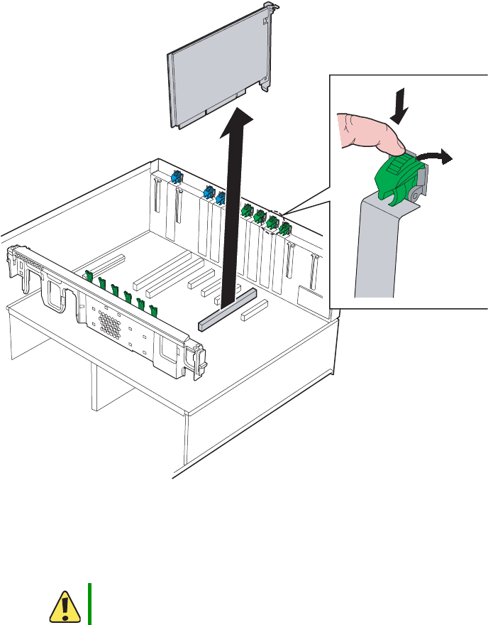
100 www.gateway.com
Chapter 4: Installing Components
4Highlight the device (card) to be removed, then click Stop.
5Wait for the PCI power LED adjacent to the selected PCI slot to turn off, then
disconnect any cables that are attached to the card.
6Push the top of the card retention clip down slightly, then rotate it out the back of
the case to open it.
7For full-length cards, press the front PCI card retainer to release the card.
8Pull up on the card to remove it. To loosen the card you can slightly rock the card
end-to-end, but do not bend the card sideways.
9Put the card in an anti-static bag for storage.
Caution
Do not touch the contacts on the bottom part of the expansion card.
Touching the contacts can cause electrostatic damage to the card.
Card
retention
clip
8510702.book Page 100 Thursday, July 7, 2005 11:21 AM

101
www.gateway.com
PCI expansion cards
10 Install an expansion slot cover over the empty slot, or install a replacement card in
the slot.
■To install an expansion slot cover, align the cover with the slot from the back of
the chassis, then press the cover into the slot. Rotate the card retention clip into
the chassis to the closed position.
■To install a replacement card, see “To install a hot-swap PCI expansion card:” on
page 102.
11 Follow the instructions in “Closing the server case” on page 72.
To remove a hot-swap PCI expansion card with hardware hot-plug interface:
1Follow the instructions in “Preventing static electricity discharge” on page 65.
2Follow the instructions in “Opening the server case” on page 66, but do not turn off
or unplug the server.
3Press the attention button adjacent the PCI slot for the card to be removed, then wait
for the power LED for that slot to turn off.
4Disconnect any cables attached to the card.
5Push the top of the card retention clip for the slot you are using down slightly, then
rotate it out the back of the case to open it (see illustration in “To remove a hot-swap
PCI expansion card with operating system hot-plug interface:” on page 99).
6For full-length cards, press the front PCI card retainer to release the card.
7Pull up on the card to remove it. To loosen the card you can slightly rock the card
end-to-end, but do not bend the card sideways.
8Put the card in an anti-static bag for storage.
Caution
Only PCI cards in slots 1 - 5 are hot-swappable. Do not attempt to
install or remove PCI cards in slots 6 or 7 without turning off your
server and disconnecting it from the AC power source.
Important To abort the hot-plug operation, press the attention button again
within five seconds.
Caution
Do not touch the contacts on the bottom part of the expansion card.
Touching the contacts can cause electrostatic damage to the card.
8510702.book Page 101 Thursday, July 7, 2005 11:21 AM

102 www.gateway.com
Chapter 4: Installing Components
9Install an expansion slot cover over the empty slot, or install a replacement card in
the slot.
■To install an expansion slot cover, align the cover with the slot from the back of
the chassis, then press the cover into the slot. Rotate the card retention clip into
the chassis to the closed position.
■To install a replacement card, see “To install a hot-swap PCI expansion card:” on
page 102.
10 Follow the instructions in “Closing the server case” on page 72.
To install a hot-swap PCI expansion card:
1Follow the instructions in “Preventing static electricity discharge” on page 65.
2Follow the instructions in “Opening the server case” on page 66, but do not turn off
or unplug the server.
3Turn off the PCI slot where you intend to install the new card by pressing the attention
button adjacent to the PCI slot.
4Remove the new PCI card from the anti-static bag and place it on an ESD-protected
work surface.
5Change the card jumpers as required (refer to the documentation that accompanied
the card), then record the serial number and jumper settings.
Caution
Only PCI cards in slots 1 - 5 are hot-swappable. Do not attempt to
install or remove PCI cards in slots 6 or 7 without turning off your
server and disconnecting it from the AC power source.
Caution
Do not touch the contacts on the bottom part of the expansion card.
Touching the contacts can cause electrostatic damage to the card.
8510702.book Page 102 Thursday, July 7, 2005 11:21 AM
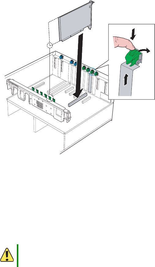
103
www.gateway.com
PCI expansion cards
6Push the top of the card retention clip for the slot you are using down slightly, then
rotate it out the back of the case to open it.
7If necessary, remove the expansion slot cover for the slot you are using by sliding it
up from inside the chassis.
8Align the card with the slot, then press down to seat the card in the slot. If you are
installing a full-length card, slide the front of the card into the front PCI card guide.
You can slightly rock the card end-to-end to seat it, but do not bend the card sideways.
9Rotate the card retention clip into the chassis to the closed position.
10 Connect any required cabling to the card.
11 Enable the new PCI card:
If you are using the operating system hot-plug interface wait for the interface to appear
on your monitor, then confirm the device to be enabled.
- OR -
Caution
Some accessory/option card outputs exceed Class 2 or power source
limits and therefore must use appropriate interconnecting cabling in
accordance with the national electrical code during installation.
8510702.book Page 103 Thursday, July 7, 2005 11:21 AM

104 www.gateway.com
Chapter 4: Installing Components
If you are using the hardware hot-plug interface, press the attention button for the
slot containing the new PCI card.
12 Wait for the power LED to turn on.
13 When the power LED has turned on, follow the instructions in “Closing the server
case” on page 72.
Cold installation or removal of PCI expansion cards
To install a non-hot-swap PCI expansion card:
1Follow the instructions in “Preventing static electricity discharge” on page 65.
2Follow the instructions in “Opening the server case” on page 66.
3Remove the new PCI card from the anti-static bag and place it on an ESD-protected
work surface.
4Change the card jumpers as required (refer to the documentation that accompanied
the card), then record the serial number and jumper settings.
5Push the top of the card retention clip for the slot you are using down slightly, then
rotate it out the back of the case to open it (see illustration in “To install a hot-swap
PCI expansion card:” on page 102).
6If necessary, remove the expansion slot cover for the slot you are using by sliding it
up from inside the chassis.
Important To abort the hot-plug operation, press the attention button again
within five seconds.
Important If the attention LED is blinking, a power fault has occurred. If this
continues, remove the new PCI card, wait for the LED to turn off, then
restart the hot-plug installation.
Caution
Damage will occur to your system if you attempt to install or remove
PCI cards in slots 6 or 7 without turning off your server and
disconnecting it from the AC power source.
Caution
Do not touch the contacts on the bottom part of the expansion card.
Touching the contacts can cause electrostatic damage to the card.
8510702.book Page 104 Thursday, July 7, 2005 11:21 AM
105
www.gateway.com
PCI expansion cards
7Align the card with the slot, then press down to seat the card in the slot. If you are
installing a full-length card, slide the front of the card into the front PCI card guide.
You can slightly rock the card end-to-end to seat it, but do not bend the card sideways.
8Rotate the card retention clip into the chassis to the closed position.
9Connect any required cabling to the card.
10 Follow the instructions in “Closing the server case” on page 72.
To remove a non-hot-swap PCI expansion card:
1Follow the instructions in “Preventing static electricity discharge” on page 65.
2Follow the instructions in “Opening the server case” on page 66.
3Disconnect any cables attached to the card.
4Push the top of the card retention clip for the slot you are using down slightly, then
rotate it out the back of the case to open it (see illustration in “To remove a hot-swap
PCI expansion card with operating system hot-plug interface:” on page 99).
5For full-length cards, press the front PCI card retainer to release the card.
6Pull up on the card to remove it. To loosen the card you can slightly rock the card
end-to-end, but do not bend the card sideways.
7Put the card in an anti-static bag for storage.
8Install an expansion slot cover over the empty slot by aligning the cover with the
slot from the back of the chassis, then pressing the cover into the slot.
9Rotate the card retention clip into the chassis to the closed position.
10 Follow the instructions in “Closing the server case” on page 72.
Caution
Some accessory/option card outputs exceed Class 2 or power source
limits and therefore must use appropriate interconnecting cabling in
accordance with the national electrical code during installation.
Caution
Damage will occur to your system if you attempt to install or remove
PCI cards in slots 6 or 7 without turning off your server and
disconnecting it from the AC power source.
Caution
Do not touch the contacts on the bottom part of the expansion card.
Touching the contacts can cause electrostatic damage to the card.
8510702.book Page 105 Thursday, July 7, 2005 11:21 AM
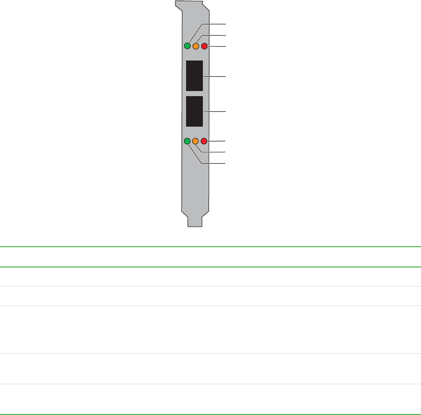
106 www.gateway.com
Chapter 4: Installing Components
Fibre channel module
The fibre channel module (optional) is an intelligent, high-performance adapter with a
Qlogic ISP2322 FC controller, designed for high-end server systems like this one. It
combines a RISC processor with two 2 Gbps transceivers, a 64-bit, 133 MHz PCI-X interface,
and a Fibre Channel Protocol Manager (FPM). Both Private Loop Direct Attach (PLDA) and
Fabric Loop Attach (FLA) devices are fully supported by the module, which operates at
either 1 Gbps (500 meter cables or less) or 2 Gbps (300 meter cables or less). For
specifications on this card, see “Fibre channel card specifications” on page 229.
Activity Green LED Orange LED Red LED
System powered off Off Off Off
Prior to firmware initialization On Off Off
Post firmware initialization
- OR -
Loss of synchronization
On Off On
1Gbps link established One flash every 4
seconds
Off Off
1Gbps activity One flash every 4
seconds
On Off
Green LED
Orange LED
Red LED
Red LED
Orange LED
Green LED
LC-style optical
connector
LC-style optical
connector
Port J1
Port J2
8510702.book Page 106 Thursday, July 7, 2005 11:21 AM

107
www.gateway.com
Fibre channel module
* Beacon is used by the Qlogic SANSurfer FE HBA Manager software to identify a specific adapter in the system.
Option ROM
During the initial boot after installation of the fibre channel module, you will see the
following information displayed during the POST:
QLogic Corporation
QLA2322 PCI Fibre Channel ROM BIOS Version x.xx Subsystem Vendor ID 8086
Copyright (C) QLogic Corporation 1993-2003 All rights reserved.
www.qlogic.com
Press <CTRL-Q> for Fast!UTIL
BIOS for Adapter 1 is disabled
QLogic adapter using IRQ number 11
Checking Adapter 0 Loop 10 125
No Fibre devices found!
ROM BIOS NOT INSTALLED
Only enable the Option ROM if your primary boot device is attached to the fibre channel
module in your server.
Operating system driver installation and configuration
Refer to the readme.txt file included with the drive for specific information on installation.
For information on driver parameters, refer to Section 2, “Driver Parameters,” in the QLogic
document Troubleshooting Guide 2Gbps Fibre Channel Host Bus Adapters, available from
download.qlogic.com/manual/17851/FC0056702-00A.pdf.
2 Gbps link established Two flashes every 4
seconds
Off Off
2 Gbps activity Two flashes every 4
seconds
On Off
Firmware error Varies Varies On
Beacon* Constant flash Constant flash Constant flash
Activity Green LED Orange LED Red LED
8510702.book Page 107 Thursday, July 7, 2005 11:21 AM

108 www.gateway.com
Chapter 4: Installing Components
Fibre channel HBA manager software
The QLogic SANsurfer FC HBA Manager is a device management software suite for the
installation, configuration, and management of QLogic-based HBAs. The software includes
asset management, remote configuration, monitoring, physical identification (beacon),
and loading of drivers onto multiple devices at one time.
The QLogic SANsurfer FC HBA Manager is available on the QLogic Web site and on the
QLogic SANsurfer CD, which is a compilation of other QLogic applications, drivers, and
interoperability resources. The QLogic SANsurfer CD is available at
www.qlogic.com/products/sanmgmnt/sansurfer_tool.asp.
Installing or removing the fibre channel module
To install or remove the fibre channel module:
1Follow the instructions in “Preventing static electricity discharge” on page 65.
2Follow the instructions in “Opening the server case” on page 66.
3Remove the memory board or memory board air baffle from slot C by following the
instructions in “Installing and removing memory boards” on page 85.
4If you are replacing a module, disconnect any cables that are attached to the old
module.
8510702.book Page 108 Thursday, July 7, 2005 11:21 AM
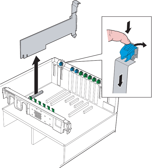
109
www.gateway.com
Fibre channel module
5Push the top of the fibre channel module retention clip down slightly, then rotate it
to the open position out the back of the case.
6If you are removing the fibre channel module:
aPull up on the module to remove it from the slot on the system board.
bPlace it in a static-free bag for storage.
cInstall an expansion slot cover by aligning it with the back of the chassis, pressing
it into the slot, then rotating the fibre channel retention clip into the closed
position on the slot cover. Go to Step 8.
8510702.book Page 109 Thursday, July 7, 2005 11:21 AM
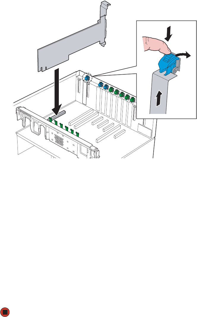
110 www.gateway.com
Chapter 4: Installing Components
7If you are installing the fibre channel module:
aIf necessary, remove the expansion slot cover by pulling it up from inside the
chassis.
bRemove the fibre channel module from its anti-static bag, being careful not to
touch the gold edge connectors at the bottom of the module.
cPlace the module on a clean, ESD-protected work surface.
dRecord the serial number from the module.
eAlign the fibre channel module with the expansion slot at the back of the chassis
and with the fibre channel module slot on the system board, then press down on
the module to seat it in the slot.
fRotate the fibre channel retention clip into the closed position on the module.
gAttach any required cables to the fibre channel module.
8Reinstall the memory board of memory board air baffle by following the instructions
in “Installing and removing memory boards” on page 85.
9Follow the instructions in “Closing the server case” on page 72.
8510702.book Page 110 Thursday, July 7, 2005 11:21 AM

111
www.gateway.com
Processors
Processors
The server requires a minimum of one Intel® Xeon™ MP processor or one Intel Xeon MP
processor with iL3 cache. The processors must be installed in sequential order, from CPU
socket 1 through CPU socket 4. Each processor socket must have either a processor and
heat sink, or a thermal blank installed
The server automatically detects the processors each time you turn on the server. Whenever
you install new processors, you should first install the most current version of the BIOS.
For more information, see “Updating the BIOS” on page 155.
Special handling of Intel Xeon processors
Intel Xeon processors require special handling procedures. Make sure you follow these
guidelines whenever you handle the processors:
■Follow the instructions in “Preventing static electricity discharge” on page 65.
■Ground yourself with a grounding heel or wrist strap and, if possible, an anti-static
smock.
■When a processor is removed from the packaging, it should only be placed on a clean,
ESD-protected work surface with its pins facing down, or installed in the server.
■When removing a processor from its packaging, keep the package flat on the surface
so that the processor does not fall out.
■Hold the processor by the sides, with the pins facing down.
■Do not touch the cartridge pin array or PCB components.
■Do not stack processors on top of each other.
Installation and removal of processors
Warning
Processors and heat sinks may be hot if the computer has been
running. Also, there may be sharp edges on the heat sinks. Consider
wearing protective gloves.
Caution
A heat sink must be installed on the processor. Installing a processor
without a heat sink could damage the processor.
Thermal blanks must be present in all processor sockets where no
processor is installed. If a processor is removed, a thermal blank must
be installed in the empty socket.
8510702.book Page 111 Thursday, July 7, 2005 11:21 AM
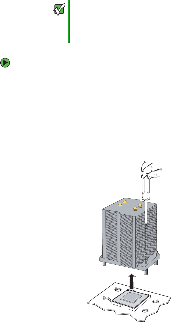
112 www.gateway.com
Chapter 4: Installing Components
To remove a processor:
1Install the most current BIOS version. For more information, see “Updating the BIOS”
on page 155.
2Follow the instructions in “Preventing static electricity discharge” on page 65.
3Follow the instructions in “Special handling of Intel Xeon processors” on page 111.
4Follow the instructions in “Opening the server case” on page 66.
5Remove the processor air baffle by following the instructions in “Removing and
installing the processor air baffle” on page 67.
6Loosen the four captive screws (one on each corner of the heatsink).
Important You must have a processor in the CPU_1 socket, or your server will
not start.
If you are upgrading your server from one processor to two (or more),
you may need to reconfigure your operating system so it can
recognize the additional processor. For more information, see your
operating system’s documentation.
8510702.book Page 112 Thursday, July 7, 2005 11:21 AM
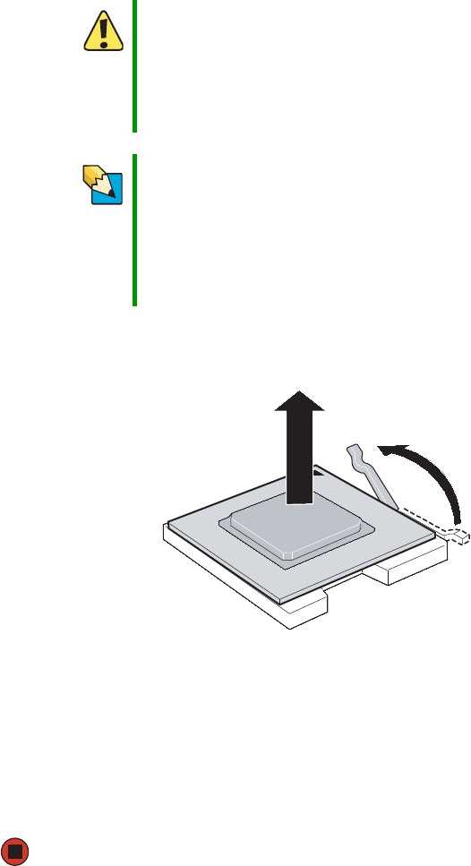
113
www.gateway.com
Processors
7Remove the heat sink by lifting it from the processor.
8Press down on the processor locking lever, push it slightly away from the processor,
then rotate the lever a full 135° to release the processor.
9Remove the processor and place it in an anti-static bag or its original package.
10 Install a replacement processor or processor thermal blank in the processor socket.
For instructions on installing a processor, see “To install a processor:” on page 114.
11 Replace the processor air baffle by following the instructions in “Removing and
installing the processor air baffle” on page 67.
12 Follow the instructions in “Closing the server case” on page 72.
Caution
The heat sink has Thermal Interface Material (TIM) on the bottom.
Be careful not to damage this material when you remove the heat
sink from the processor.
If removing the heat sink also pulls the processor out of the processor
socket, the processor could be damaged. Check the pins on the
processor to make sure they are not bent or damaged.
Tips & Tricks
To aid in separating the heat sink from the processor, turn on the
server for a few minutes prior to attempting to remove the processor.
This will warm the thermal interface material and help prevent the
processor from pulling out of a closed socket. Make sure the heat
sink is cool to the touch before attempting to remove it.
If the heat sink still sticks to the processor, twist it slightly to release
it, then try again.
8510702.book Page 113 Thursday, July 7, 2005 11:21 AM

114 www.gateway.com
Chapter 4: Installing Components
To install a processor:
1Install the most current BIOS version. For more information, see “Updating the BIOS”
on page 155.
2Follow the instructions in “Preventing static electricity discharge” on page 65.
3Follow the instructions in “Special handling of Intel Xeon processors” on page 111.
4Follow the instructions in “Opening the server case” on page 66.
5Remove the processor air baffle by following the instructions in “Removing and
installing the processor air baffle” on page 67.
Caution
A heat sink must be installed on the processor. Installing a processor
without a heat sink could damage the processor.
Thermal blanks must be present in all processor sockets where no
processor is installed. If a processor is removed, a thermal blank must
be installed in the empty socket.
Caution
When processors are installed in CPU sockets 3 and 4 (that is, more
than two processors are installed in this server), you must install
VRMs for the additional processors. For more information, see
“Processor VRM requirements” on page 118.
Important You must have a processor in the CPU_1 socket, or your server will
not start.
If you are upgrading your server from one processor to two (or more),
you may need to reconfigure your operating system so it can
recognize the additional processor. For more information, see your
operating system’s documentation.
8510702.book Page 114 Thursday, July 7, 2005 11:21 AM
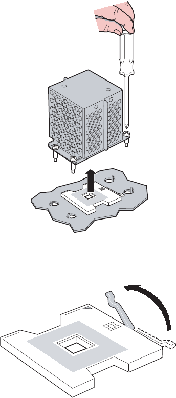
115
www.gateway.com
Processors
6If a processor thermal blank is installed, remove it by loosening the four screws (one
at each corner) and lifting the thermal blank from the processor socket.
7Make sure that the processor release lever is in the open position.
8510702.book Page 115 Thursday, July 7, 2005 11:21 AM
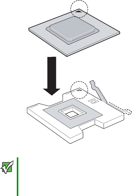
116 www.gateway.com
Chapter 4: Installing Components
8Install the new processor into the processor socket. Make sure that:
■You install the processors in order, from CPU socket 1 through CPU socket 4, with
the new processor being installed in the next available socket
■The triangular arrow on the corner of the processor aligns with the triangular hole
on the corner of the processor socket
■The processor is flush with the socket.
9Press the processor locking lever down until it clicks into place.
Important If you install two or more processors onto the system board, for best
performance the processors should be the same speed. Otherwise,
applications that detect processor speed could cause problems.
If only one processor is installed, it must be installed in the CPU 1
socket.
8510702.book Page 116 Thursday, July 7, 2005 11:21 AM
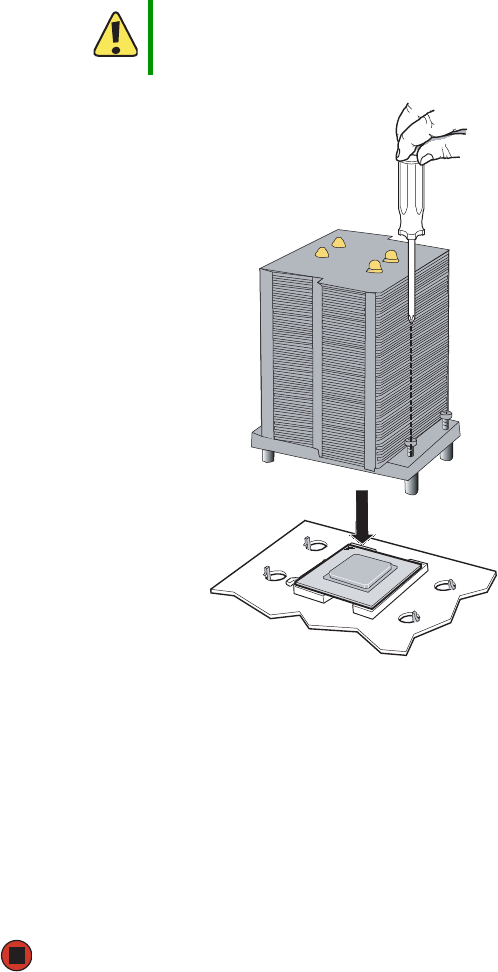
117
www.gateway.com
Processors
10 Place the heat sink on the processor, making sure the thermal grease is applied
correctly or the Thermal Interface Material (TIM) is aligned between the heat sink and
the processor.
11 Line up the four captive screws with the four posts surrounding the processor, then
gradually and evenly tighten the four captive screws to secure the heat sink to the
system board (see “Torque settings” on page 64).
12 Install VRMs as necessary (see “Processor VRM requirements” on page 118 and
“Installing and removing VRMs” on page 118).
13 Replace the processor air baffle by following the instructions in “Removing and
installing the processor air baffle” on page 67.
14 Follow the instructions in “Closing the server case” on page 72.
Caution
Failure to apply the Thermal Interface Material or thermal grease
between the processor and the heat sink could result in damage to
the processor and the server.
8510702.book Page 117 Thursday, July 7, 2005 11:21 AM

118 www.gateway.com
Chapter 4: Installing Components
Processor VRM requirements
This server requires the installation of two different types of VRMs (Voltage Regulator
Modules). The number and types of VRMs required depends on the number of processors
installed. Before installing or removing processors, refer to the following guidelines:
Installing and removing VRMs
When a third processor is installed in your server (in CPU socket 3), two VRMs (one VRM
9.1 for the cache and one VRM 10.2LD for the processor core) also need to be installed
at the same time. Also, when a fourth processor is installed, an additional VRM 10.2LD
must be installed.
To install a processor cache VRM:
1Follow the instructions in “Preventing static electricity discharge” on page 65.
2Follow the instructions in “Opening the server case” on page 66.
3Remove the processor air baffle by following the instructions in “Removing and
installing the processor air baffle” on page 67.
4Pull the plastic tabs away from the sides of the VRM socket.
Number of
processors
installed
VRMs required
1 No VRM required
2 No VRM required
3 One 9.1 volt processor cache VRM required
One 10.2LD volt processor core VRM required
4 One 9.1 volt processor cache VRM required
Two 10.2LD volt processor core VRMs required
8510702.book Page 118 Thursday, July 7, 2005 11:21 AM
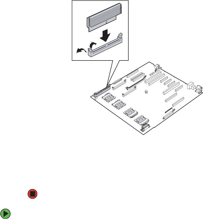
119
www.gateway.com
Processors
5Holding the VRM by the edges, align the notch on the bottom edge of the VRM with
the notch in the VRM socket and press the VRM firmly into the socket.
6Make sure the tabs on the sides of the VRM socket close securely.
7Replace the processor air baffle by following the instructions in “Removing and
installing the processor air baffle” on page 67.
8Follow the instructions in “Closing the server case” on page 72.
To remove a processor cache VRM:
1Follow the instructions in “Preventing static electricity discharge” on page 65.
2Follow the instructions in “Opening the server case” on page 66.
3Remove the processor air baffle by following the instructions in “Removing and
installing the processor air baffle” on page 67.
4Gently spread the retaining clips at each end of the VRM socket causing the VRM to
lift from the socket.
8510702.book Page 119 Thursday, July 7, 2005 11:21 AM
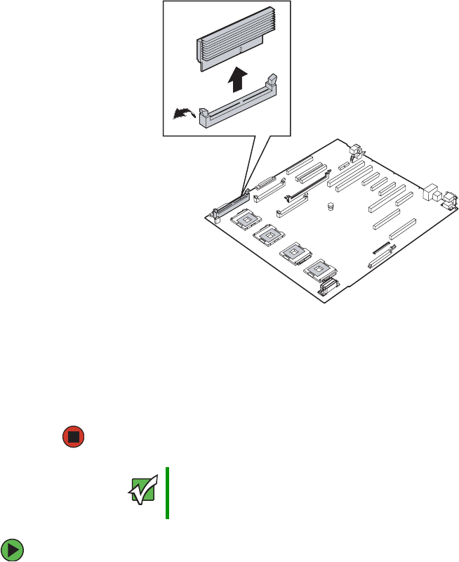
120 www.gateway.com
Chapter 4: Installing Components
5Holding the VRM by the edges, lift it from the socket.
6Place the VRM into an anti-static bag for storage.
7Replace the processor air baffle by following the instructions in “Removing and
installing the processor air baffle” on page 67.
8Follow the instructions in “Closing the server case” on page 72.
To install a processor core VRM:
1Follow the instructions in “Preventing static electricity discharge” on page 65.
2Follow the instructions in “Opening the server case” on page 66.
3Remove the processor air baffle by following the instructions in “Removing and
installing the processor air baffle” on page 67.
Important The processor core VRM sockets are located on the system board,
under the center brace, however you do not need to remove the center
brace to install or remove the VRMs.
8510702.book Page 120 Thursday, July 7, 2005 11:21 AM
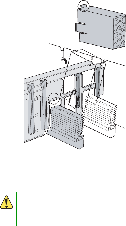
121
www.gateway.com
Processors
4Remove the memory boards or memory board air baffles from memory slots C and
D by following the instructions in “Installing and removing memory boards” on
page 85.
5Remove the fibre channel module by following the instructions in “Installing or
removing the fibre channel module” on page 108.
6If you are installing the VRM for the fourth processor, remove the VRM air baffle by
pushing down on the top of the baffle and pulling the baffle away at an angle from
the center brace.
7Pull the plastic tabs away from the sides of the VRM socket.
8Holding the VRM by the edges, align the notch on the bottom edge of the VRM with
the notch in the VRM socket and press the VRM firmly into the socket.
9Make sure the tabs on the sides of the VRM socket close securely.
Caution
Do not use excessive force if the VRM converter does not install
easily. The notch in the VRM and the tab in the VRM socket are
designed to prevent incorrect installation. Forcing the wrong VRM into
the socket, or forcing the correct VRM into the socket incorrectly,
could result in damage to the VRM or the socket.
8510702.book Page 121 Thursday, July 7, 2005 11:21 AM

122 www.gateway.com
Chapter 4: Installing Components
10 If you are installing the VRM for the fourth processor, reinstall the VRM air baffle.
11 Replace the fibre channel module by following the instructions in “Installing or
removing the fibre channel module” on page 108.
12 Replace the memory boards or memory board air baffles into memory slots C and D
by following the instructions in “Installing and removing memory boards” on
page 85.
13 Replace the processor air baffle by following the instructions in “Removing and
installing the processor air baffle” on page 67.
14 Follow the instructions in “Closing the server case” on page 72.
To remove a processor core VRM:
1Follow the instructions in “Preventing static electricity discharge” on page 65.
2Follow the instructions in “Opening the server case” on page 66.
3Remove the processor air baffle by following the instructions in “Removing and
installing the processor air baffle” on page 67.
4Remove the memory boards or memory board air baffles from memory slots C and
D by following the instructions in “Installing and removing memory boards” on
page 85.
5Remove the fibre channel module by following the instructions in “Installing or
removing the fibre channel module” on page 108.
Important The processor core VRM sockets are located on the system board,
under the center brace, however you do not need to remove the center
brace to install or remove the VRMs.
8510702.book Page 122 Thursday, July 7, 2005 11:21 AM
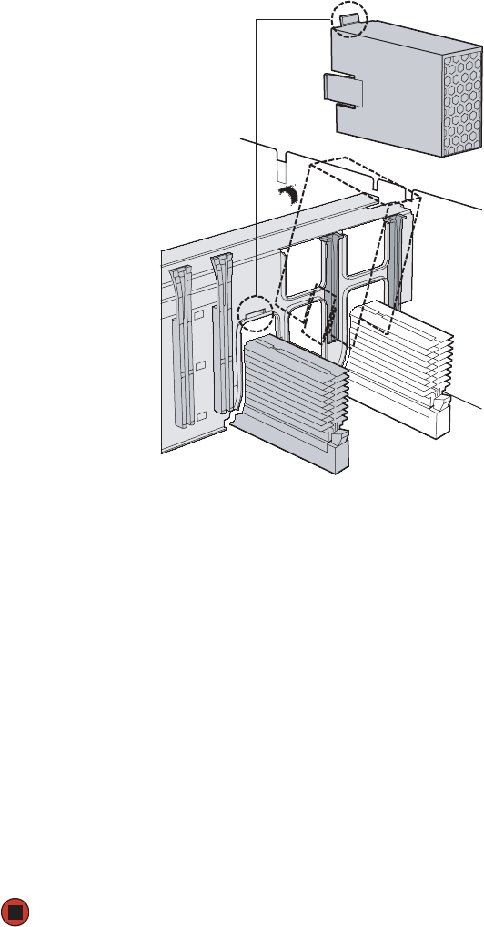
123
www.gateway.com
Processors
6If you are removing the VRM for the fourth processor, remove the VRM air baffle by
pushing down on the top of the baffle and pulling the baffle away at an angle from
the center brace.
7Gently spread the retaining clips at each end of the VRM socket which makes the
VRM pop up from the socket.
8Holding the VRM by the edges, remove it from the socket.
9Place the VRM into an anti-static bag for storage.
10 Reinstall the VRM air baffle, if you removed it.
11 Replace the fibre channel module by following the instructions in “Installing or
removing the fibre channel module” on page 108.
12 Replace the memory boards or memory board air baffles into memory slots C and D
by following the instructions in “Installing and removing memory boards” on
page 85.
13 Replace the processor air baffle by following the instructions in “Removing and
installing the processor air baffle” on page 67.
14 Follow the instructions in “Closing the server case” on page 72.
8510702.book Page 123 Thursday, July 7, 2005 11:21 AM
124 www.gateway.com
Chapter 4: Installing Components
Installing an Intel Management Module
(IMM)
To install an Intel Management Module (IMM):
1Uninstall the Gateway Server Manager (GSM) software from your server.
2Follow the instructions in “Preventing static electricity discharge” on page 65.
3Follow the instructions in “Opening the server case” on page 66.
4Remove the processor air baffle by following the instructions in “Removing and
installing the processor air baffle” on page 67.
5Remove the memory boards or memory board air baffles from slots A and B, by
following the instructions in “Installing and removing memory boards” on page 85.
6Install the nylon standoff into the hole in the IMM module board which corresponds
to the hole in the system board (see the illustration on page 125).
Important The snap fit end of the standoff go into the hole in the IMM module
board. The snap lock end of the standoff go into hole in the system
board.
Snap fit end goes into
IMM board.
Snap lock end goes
into system board.
8510702.book Page 124 Thursday, July 7, 2005 11:21 AM
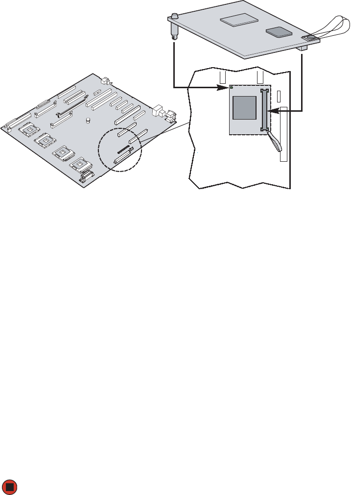
125
www.gateway.com
Installing an Intel Management Module (IMM)
7Find the IMM connector on the right side of the system board.
8Grasp the module board by one edge and the plastic handling strap (close to the
mounting connector), align the board with the IMM connector on the system board,
then gently apply pressure to seat the module.
Make sure the module is fully seated and the nylon standoffs are inserted into the
corresponding holes in the system board.
9Replace the memory boards or memory board air baffles into memory slots C and D
by following the instructions in “Installing and removing memory boards” on
page 85.
10 Replace the processor air baffle by following the instructions in “Removing and
installing the processor air baffle” on page 67.
11 Follow the instructions in “Closing the server case” on page 72.
12 Follow the instructions in “Updating the BMC firmware” on page 47.
Following the installation of a new Intel Management Module, you must reinstall the
GSM software (from a CD which accompanied your server) and update the FRU/SDR
(see “FRU/SDR Load utility” on page 54). When you subsequently reboot your server,
the GSM software will take over management of the server.
For information on the Embedded Web Server, see “Embedded Web Server” on
page 50.
8510702.book Page 125 Thursday, July 7, 2005 11:21 AM

126 www.gateway.com
Chapter 4: Installing Components
Installing and removing the ROMB (RAID
on Motherboard) activation key and
dedicated RAID memory
Functionality for RAID levels 5, 10, and 50 is enabled by using the optional Intel RAID
Activation Key (1-wire serial security EEPROM) and dedicated RAID memory installed in
the onboard RAID cache memory socket. The system BIOS provides the IOP ROMB setup
option in which the SCSI and Intel RAID Controller SROMBU42E options can be selected
(SCSI mode: IOP ROMB = Disabled, or SROMBU42E mode: IOP ROMB = Enabled).
If IOP ROMB is enabled, the system boots using the ROMB option ROM. In this case, the
SCSI channels are used by the ROMB solution to enable RAID 5, 10, and 50 functionality.
If the RAID Activation Key and RAID DIMM are not present, the system boots in SCSI
mode and the IOP332 ROMB option in system BIOS will be grayed out.
Your server’s system board includes a RAID cache memory socket. This DIMM is not shared
with main memory and is for exclusive use as RAID cache for ROMB functionality. The
ROMB subsystem supports one 128 MB, 256 MB or 512 MB DDR400 un-buffered ECC
DIMM, enabling higher performance operation (write back cache). For enhanced data
protection and maximum performance, the system board also supports the RAID Smart
Battery accessory, which provides up to 72 hours of battery back-up. For more information
on the RAID Smart Battery option, see “Installing and removing the Smart Battery” on
page 129.
To install the RAID activation key and RAID DIMM:
1Follow the instructions in “Preventing static electricity discharge” on page 65.
2Follow the instructions in “Opening the server case” on page 66.
3Remove the processor air baffle by following the instructions in “Removing and
installing the processor air baffle” on page 67.
4Remove the memory board or memory board air baffle from slot C by following the
instructions in “Installing and removing memory boards” on page 85.
Important The IOP332 ROMB option in BIOS Setup is grayed out unless a valid
Intel RAID Activation Key and compatible RAID memory are present.
Important The onboard RAID (levels 1 and 2) and the ROMB RAID (levels 5,
10, and 50) are mutually exclusive solutions. Only one of the two may
be used at a time. A RAID array (using one or more drives) transfer
from one mode to the other is not supported.
8510702.book Page 126 Thursday, July 7, 2005 11:21 AM
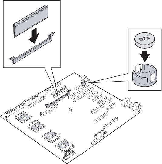
127
www.gateway.com
Installing and removing the ROMB (RAID on Motherboard) activation key and dedicated
5Remove the PCI expansion card from PCI slot 7 (if installed) by following the
instructions in “Cold installation or removal of PCI expansion cards” on page 104.
6Remove the RAID activation key and RAID DIMM from their anti-static packages.
7Insert the activation key into its socket on the system board (see “System board” on
page 5 for the location of the socket.)
Push the key into the socket until it is below the two retaining clips.
8Pull the plastic tabs away from the sides of the DIMM socket. If you are replacing a
DIMM, remove the old one.
8510702.book Page 127 Thursday, July 7, 2005 11:21 AM
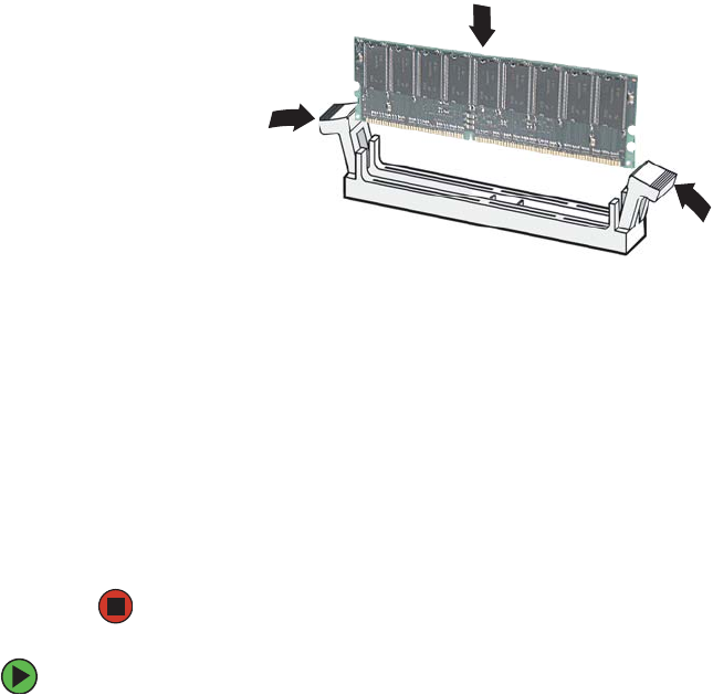
128 www.gateway.com
Chapter 4: Installing Components
9Holding the DIMM by the edges, align the notch on the bottom edge of the DIMM
with the notch in the DIMM socket and press the DIMM firmly into the socket. The
tabs on the sides of the DIMM socket should secure the DIMM automatically.
10 Reinstall the PCI expansion card into PCI slot 7 (if removed) by following the
instructions in “Cold installation or removal of PCI expansion cards” on page 104.
11 Reinstall the memory board or memory board air baffle by following the instructions
in “Installing and removing memory boards” on page 85.
12 Replace the processor air baffle by following the instructions in “Removing and
installing the processor air baffle” on page 67.
13 Follow the instructions in “Closing the server case” on page 72.
14 Configure the BIOS settings to enable the ROMB option.
To remove the RAID activation key and RAID DIMM:
1Remove the processor air baffle by following the instructions in “Removing and
installing the processor air baffle” on page 67.
2Remove the memory board or memory board air baffle from slot C by following the
instructions in “Installing and removing memory boards” on page 85.
3Remove the PCI expansion card from PCI slot 7 (if installed) by following the
instructions in “Cold installation or removal of PCI expansion cards” on page 104.
4Insert the end of a small, flat-bladed screwdriver under the plastic tab on the snap-on
plastic retainer holding the RAID activation key on the system board, then gently pry
the key from the holder.
8510702.book Page 128 Thursday, July 7, 2005 11:21 AM
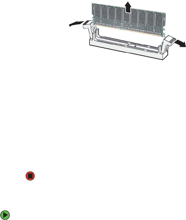
129
www.gateway.com
Installing and removing the ROMB (RAID on Motherboard) activation key and dedicated
5Gently spread the retaining clips at each end of the RAID DIMM socket causing the
DIMM to lift from the socket.
6Holding the DIMM by the edges, lift it from the socket.
7Place the RAID activation key and the RAID DIMM into anti-static bags for storage.
8Reinstall the PCI expansion card into PCI slot 7 (if removed) by following the
instructions in “Cold installation or removal of PCI expansion cards” on page 104.
9Reinstall the memory board or memory board air baffle for slot C by following the
instructions in “Installing and removing memory boards” on page 85.
10 Replace the processor air baffle by following the instructions in “Removing and
installing the processor air baffle” on page 67.
11 Follow the instructions in “Closing the server case” on page 72.
12 Configure the BIOS settings to disable the ROMB option.
Installing and removing the Smart Battery
To install the smart battery:
1Follow the instructions in “Preventing static electricity discharge” on page 65.
2Follow the instructions in “Opening the server case” on page 66.
3Remove the processor air baffle by following the instructions in “Removing and
installing the processor air baffle” on page 67.
4Remove the memory board or memory board air baffle from slot D by following the
instructions in “Installing and removing memory boards” on page 85.
8510702.book Page 129 Thursday, July 7, 2005 11:21 AM
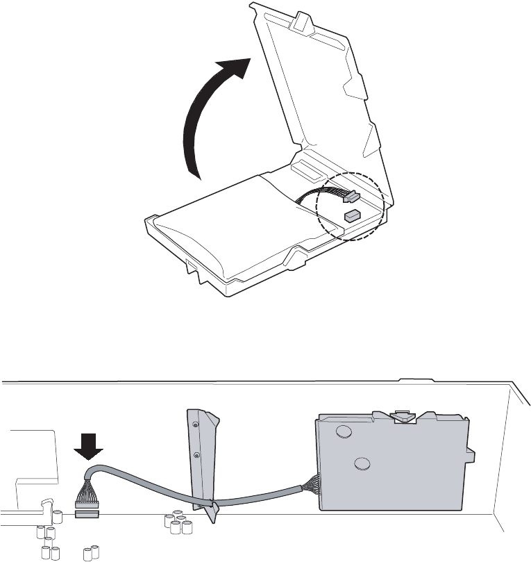
130 www.gateway.com
Chapter 4: Installing Components
5Open the battery case, then connect the cable inside the battery case.
6After closing the battery case, route the battery cable through the holder on the side
of the chassis.
7Attach the cable to the BBU connector (J1H1 - 2×10) on the system board. See “System
board” on page 5 for the location of the connector.
8510702.book Page 130 Thursday, July 7, 2005 11:21 AM
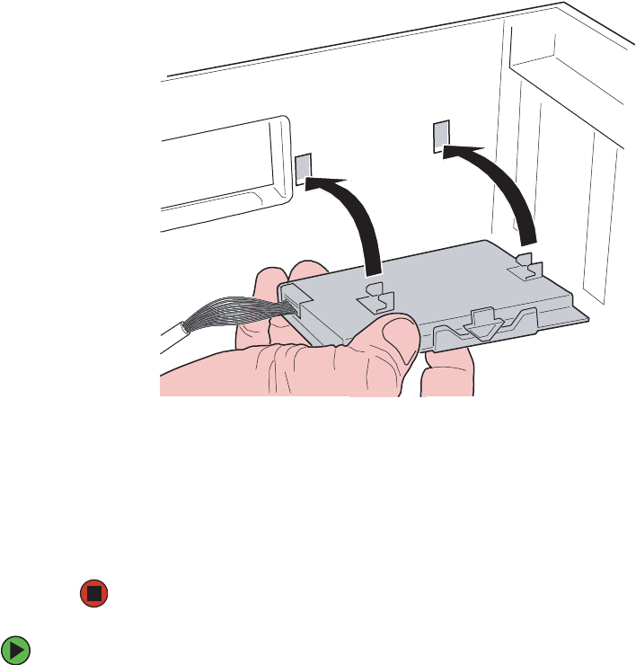
131
www.gateway.com
Installing and removing the ROMB (RAID on Motherboard) activation key and dedicated
8Engage the retention tabs on the back of the battery with the matching slots in the
side of the chassis, then push the battery to the left to latch it into place.
9Reinstall the memory board or memory board air baffle into slot D by following the
instructions in “Installing and removing memory boards” on page 85.
10 Replace the processor air baffle by following the instructions in “Removing and
installing the processor air baffle” on page 67.
11 Follow the instructions in “Closing the server case” on page 72.
To remove the smart battery:
1Follow the instructions in “Preventing static electricity discharge” on page 65.
2Follow the instructions in “Opening the server case” on page 66.
3Remove the processor air baffle by following the instructions in “Removing and
installing the processor air baffle” on page 67.
4Remove the memory board or memory board air baffle from slot D by following the
instructions in “Installing and removing memory boards” on page 85.
5Disconnect the battery cable from the system board.
8510702.book Page 131 Thursday, July 7, 2005 11:21 AM

132 www.gateway.com
Chapter 4: Installing Components
6Push the battery to the right to disengage it from the side of the chassis, then remove
it from the chassis.
7Reinstall the memory board or memory board air baffle into slot D by following the
instructions in “Installing and removing memory boards” on page 85.
8Replace the processor air baffle by following the instructions in “Removing and
installing the processor air baffle” on page 67
9Follow the instructions in “Closing the server case” on page 72.
8510702.book Page 132 Thursday, July 7, 2005 11:21 AM
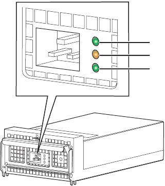
133
www.gateway.com
Power subsystem
Power subsystem
The power subsystem includes the power supply modules, the power distribution board,
and the plug-in VRMs.
The power subsystem can be configured in either of two ways:
■Two power supply modules installed providing 1 + 1 redundant power at 220 VAC,
115/120/127 VAC, and 100/110 VAC
■One power supply module installed providing non-redundant power at 220 VAC,
115/120/127 VAC, and 100/110 VAC
Each current-sharing power supply module has auto-ranging input and provides 1570W
of power when operated between 170 VAC and 264 VAC. Each module requires a power
cord to supply AC power to the server. When two power supply modules are installed,
the system supports (1+1) power cord redundancy, which lets the server be powered from
two separate AC sources. In this configuration, the server will continue to operate without
interruption when one of the AC sources fails. The modules are capable of power-safe
monitoring.
Power supply module LEDs indicate the condition of the module and the AC power source.
Fault LED (orange)
Power good LED (green)
AC OK LED (green)
8510702.book Page 133 Thursday, July 7, 2005 11:21 AM
134 www.gateway.com
Chapter 4: Installing Components
Replacing a power supply module
Your server uses as many as two hot-swappable redundant power supplies. If two power
supply modules are installed and one of them fails, the other power supply module
supports the server while you replace the failed module. You do not need to turn off the
server or disconnect peripheral devices to replace a failed power supply module in this
configuration. If only one power supply module is installed, the server must be turned
off to replace it.
If you are adding a redundant power supply module to your server, you must update the
FRU/SDR after the installation is complete. For more information, see “FRU/SDR Load
utility” on page 54.
LED Location Description
Power good
LED (green)
Top This LED is lit whenever the power is turned on
Fault LED
(orange)
Center This LED is lit when a power rail has failed, even if
the power supply is in a latched state. The only time
this LED is not lit during a fault condition is if the
3.3VSB is lost.
This LED is not lit when the server is turned off.
AC OK LED
(green)
Bottom This LED is lit when the power supply module is
plugged into an active AC power source.
Warning
The power supply modules in this server contain no user-serviceable
parts. Only a qualified computer technician should service the power
supply modules.
Your server comes with 3-wire AC power cords fitted with the correct
plug style for your region. If this plug does not match the connector
on your surge protector, UPS, or wall outlet, do not attempt to modify
the plug in any way. Use a UPS or wall outlet that is appropriate for
the supplied AC power cords.
Caution
Because of chassis airflow disruption, a power supply module bay
should never be empty for more than two minutes when the server
power is on. Possible damage to system components could result if
the bay is empty for more than five minutes.
If your server is configured with only one power supply module, an
active fan blank must be installed in the second power supply module
bay.
8510702.book Page 134 Thursday, July 7, 2005 11:21 AM
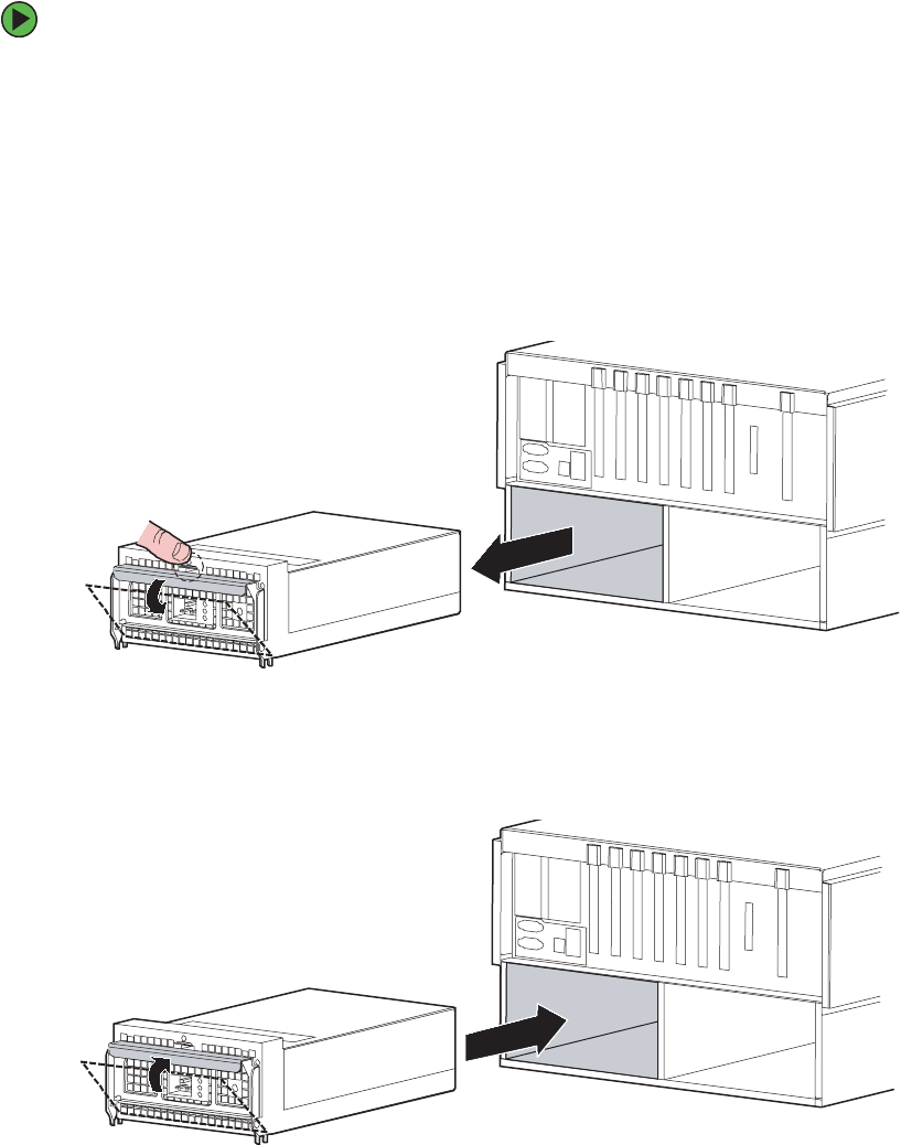
135
www.gateway.com
Power subsystem
To replace a power supply module or active fan blank:
1Examine the LED indicators on the back of each power supply modules to identify
the failed module. The power supply module has failed if the center Fault LED (orange)
indicator is on. If your server has two power supply modules, go to Step 3.
2Turn off the server.
3Unplug the power cord from the failed power supply module.
4Push down the thumb tab to unlock the power supply module (or active fan blank)
handle, then pull down the handle to disengage the module (or active fan blank) from
the chassis and pull the module (or active fan blank) straight out from the server.
5Place the power supply module (or active fan blank) on a clean, ESD-protected surface.
6With the handle in the open position, slide the new power supply module (or active
fan blank) into the power supply module bay until it stops.
7Push the handle up against the power supply module (or active fan blank) until the
thumb tab clicks into place.
8510702.book Page 135 Thursday, July 7, 2005 11:21 AM

136 www.gateway.com
Chapter 4: Installing Components
8Plug the power cord into the AC connector on the power supply module.
9If your server only has a single power supply module, turn on the server.
10 The new power supply module is ready if the green Power Good LED (top) and green
AC OK LED are both on.
Replacing a power distribution board
Your server uses a power distribution board to enable the hot-swap capability and distribute
power to the system. If the power distribution board fails, you will need to turn off the
server and disconnect all AC power to the system prior to replacing it.
To replace a power distribution board:
1Follow the instructions in “Preventing static electricity discharge” on page 65.
2Follow the instructions in “Opening the server case” on page 66.
3Remove the power supply module (remove both if two are installed) by following the
instructions in “Replacing a power supply module” on page 134.
4Remove the processor air baffle by following the instructions in “Removing and
installing the processor air baffle” on page 67.
5Remove the system board by following the instructions in “Replacing the system
board” on page 149.
6Remove the SCSI backplane by following the instructions in “Replacing the SCSI
hot-swap backplane” on page 139.
7Disconnect all power cables from the power distribution board, noting their locations
and orientation. (You will reconnect the cables after you install the new board.)
8510702.book Page 136 Thursday, July 7, 2005 11:21 AM
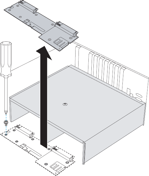
137
www.gateway.com
Power subsystem
8Remove the seven (7) screws securing the power distribution board to the chassis, then
lift the board from the chassis and place it in an anti-static bag for storage.
9Remove the new power distribution board from its package and align it with the seven
screw holes on the chassis.
8510702.book Page 137 Thursday, July 7, 2005 11:21 AM
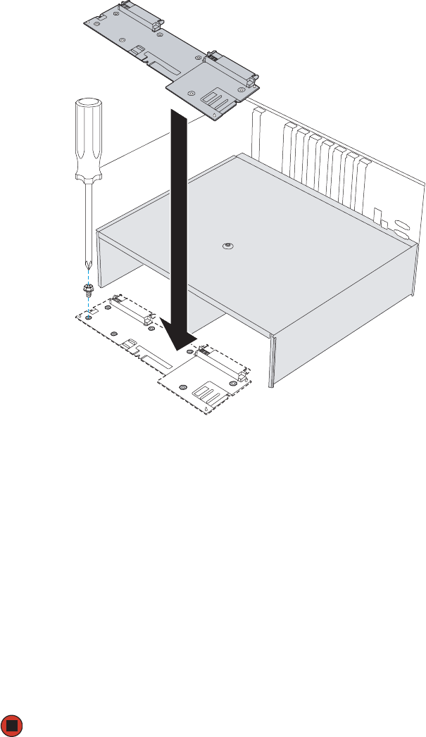
138 www.gateway.com
Chapter 4: Installing Components
10 Secure the new power distribution board to the chassis with the seven screws you
previously removed.
11 Connect all power cables that you previously removed from the power distribution
board.
12 Reinstall the SCSI backplane by following the instructions in “Replacing the SCSI
hot-swap backplane” on page 139.
13 Reinstall the power supply module (remove both if two were removed) by following
the instructions in “Replacing a power supply module” on page 134.
14 Reinstall the system board by following the instructions in “Replacing the system
board” on page 149.
15 Reinstall the processor air baffle by following the instructions in “Removing and
installing the processor air baffle” on page 67.
16 Follow the instructions in “Closing the server case” on page 72.
17 Connect power to the server and restart.
8510702.book Page 138 Thursday, July 7, 2005 11:21 AM

139
www.gateway.com
Replacing the SCSI hot-swap backplane
Replacing the SCSI hot-swap backplane
Your server can hold as many as ten SCSI hot-swap drives in a hot-swap drive cage. The
hot-swap drive cage is connected to the SCSI backplane, which provides power and data
interface between the drives and the server. The SCSI hot-swap backplane is located behind
the SCSI drive bays.
To replace the SCSI hot-swap backplane:
1Follow the instructions in “Preventing static electricity discharge” on page 65.
2Follow the instructions in “Opening the server case” on page 66.
3Remove the processor air baffle by following the instructions in “Removing and
installing the processor air baffle” on page 67.
4Remove all of the drives from the hot-swap cage, and note the location of each drive.
For instructions, see “Installing a hot-swap hard drive” on page 80.
5Remove all memory boards and memory board air baffles by following the instructions
in “Installing and removing memory boards” on page 85.
6Remove all PCI expansion cards by following the instructions in “Cold installation
or removal of PCI expansion cards” on page 104.
7Remove the center brace by following the instructions in “Removing and installing
the center brace” on page 69.
8Remove the system board by following the instructions in “Replacing the system
board” on page 149.
9Disconnect all cables from the SCSI hot-swap backplane.
Caution
When removing SCSI drives in preparation to replace the SCSI
hot-swap backplane, note their locations to make sure they are
reinstalled in their original positions. Failure to reinstall the drives in
the original locations could result in loss of data.
8510702.book Page 139 Thursday, July 7, 2005 11:21 AM
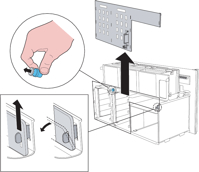
140 www.gateway.com
Chapter 4: Installing Components
10 Pull out the blue, spring-loaded plunger (located at the top of the SCSI hot-swap
backplane) that secures the backplane to the chassis, then pull the board up slightly
to disengage the ten retention tabs holding the board to the chassis.
11 Tilt the SCSI hot-swap backplane back slightly, then lift it from the server and place
it in an anti-static bag for storage.
8510702.book Page 140 Thursday, July 7, 2005 11:21 AM
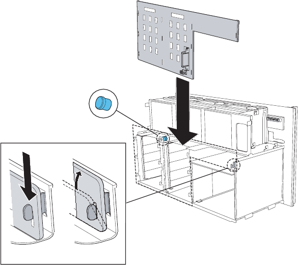
141
www.gateway.com
Replacing the SCSI hot-swap backplane
12 Remove the new SCSI hot-swap backplane from its package, then place it in the chassis
by engaging the bottom three slots in the board with the three lower retention tabs
in the chassis.
13 Move the top of the board forward, engaging the rest of the slots with the other
retention tabs on the chassis, until all ten tabs are through the ten slots in the board.
14 Slide the SCSI hot-swap backplane board down until the board is firmly in place on
the chassis and the blue, spring-loaded plunger is fully seated.
15 Reconnect all cables to the SCSI hot-swap backplane.
16 Reinstall the system board by following the instructions in “Replacing the system
board” on page 149.
17 Reinstall the center brace by following the instructions in “Removing and installing
the center brace” on page 69.
18 Reinstall all PCI expansion cards by following the instructions in “Cold installation
or removal of PCI expansion cards” on page 104.
19 Reinstall all memory boards and memory board air baffles by following the
instructions in “Installing and removing memory boards” on page 85.
8510702.book Page 141 Thursday, July 7, 2005 11:21 AM

142 www.gateway.com
Chapter 4: Installing Components
20 Reinstall the processor air baffle by following the instructions in “Removing and
installing the processor air baffle” on page 67
21 Follow the instructions in “Closing the server case” on page 72.
22 Reinstall all of the drives into the hot-swap drive bays. Make sure that you replace
the drives in the correct order by referring to your notes from Step 4.
8510702.book Page 142 Thursday, July 7, 2005 11:21 AM
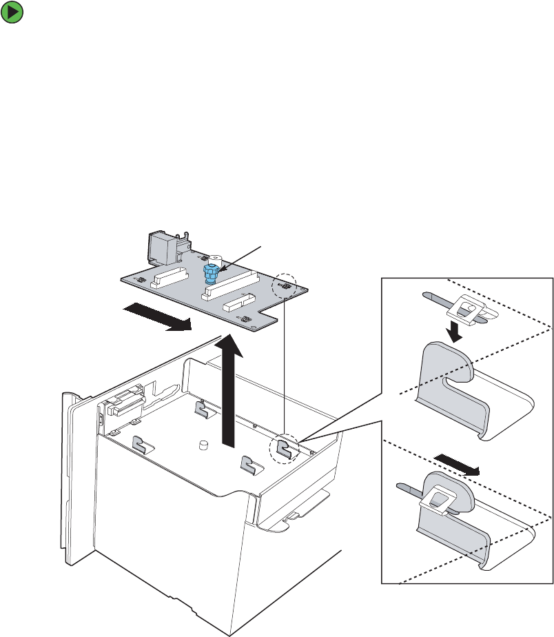
143
www.gateway.com
Replacing the front panel I/O board
Replacing the front panel I/O board
To replace the front panel I/O board:
1Follow the instructions in “Preventing static electricity discharge” on page 65.
2Follow the instructions in “Opening the server case” on page 66.
3Remove the processor air baffle by following the instructions in “Removing and
installing the processor air baffle” on page 67.
4Disconnect the front panel I/O board and control panel cables from the front panel
board.
5Loosen the blue, captive thumbscrew in the center of the front panel I/O board, then
slide the board back until the mounting tabs disengage from the board.
6Remove the board from the server and store it in an anti-static bag.
Blue, captive thumbscrew
Mounting
tab
8510702.book Page 143 Thursday, July 7, 2005 11:21 AM
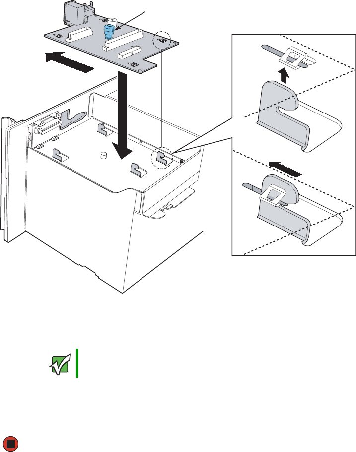
144 www.gateway.com
Chapter 4: Installing Components
7Remove the new front panel I/O board from its package and place it in the chassis,
engaging the mounting tabs on the chassis with the slots in the new board.
8Slide the front panel I/O board forward until it is seated on the mounting tabs, then
tighten the blue, captive thumbscrew to secure the board. See “Torque settings” on
page 64 for correct tightening specifications.
9Connect the front panel I/O board and control panel cables to the new front panel
I/O board.
10 Reinstall the processor air baffle by following the instructions in “Removing and
installing the processor air baffle” on page 67.
11 Follow the instructions in “Closing the server case” on page 72.
Important Make sure that the pins on the front panel I/O board line up correctly
with the front panel cable connector.
Blue, captive thumbscrew
Mounting
tab
8510702.book Page 144 Thursday, July 7, 2005 11:21 AM
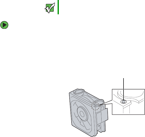
145
www.gateway.com
Replacing a hot-swap fan
Replacing a hot-swap fan
If you are adding redundant hot-swap fans to your server, you must update the FRU/SDR.
For more information, see “FRU/SDR Load utility” on page 54.
To replace a hot-swap fan:
1Follow the instructions in “Preventing static electricity discharge” on page 65.
2Follow the instructions in “Opening the server case” on page 66, but do not unplug
or turn off the server.
3Locate the fan to be replaced. An orange LED indicates a failed fan.
Important Make sure that you replace a fan with an identical replacement fan.
Fan LED
8510702.book Page 145 Thursday, July 7, 2005 11:21 AM
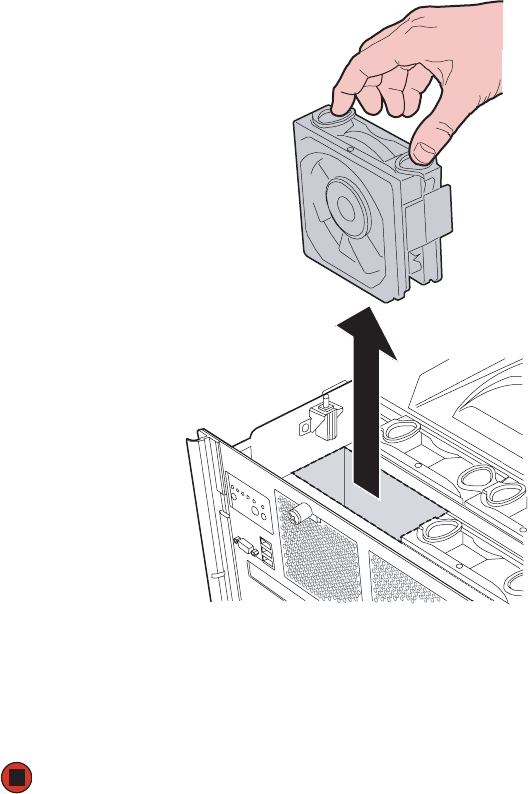
146 www.gateway.com
Chapter 4: Installing Components
4Squeeze the fan latches together to release the fan, then lift the fan from the chassis.
5Orient the new fan in the same direction as the old fan (and existing fans), then insert
the new fan into the fan slot until it snaps into place.
6Wait for the new fan to spin up, then follow the instructions in “Closing the server
case” on page 72.
8510702.book Page 146 Thursday, July 7, 2005 11:21 AM
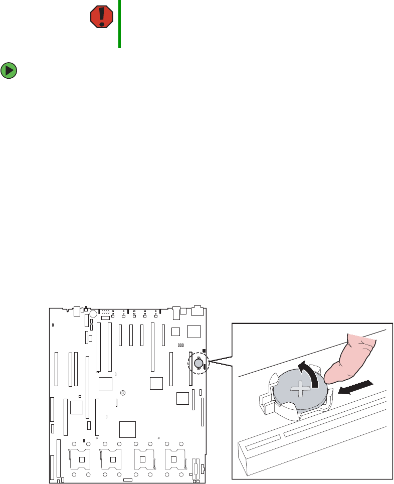
147
www.gateway.com
Replacing the CMOS battery
Replacing the CMOS battery
If the server clock does not keep time or the settings in the BIOS Setup utility are not saved
when you turn off the server, replace the CMOS battery with an equivalent battery.
To replace the battery:
1Print the appendix for BIOS Settings in this guide.
2Follow the instructions in “Opening the BIOS Setup utility” on page 154.
3Record the BIOS settings on your printout, then close the utility.
4Turn off your server, then follow the instructions in “Preventing static electricity
discharge” on page 65.
5Follow the instructions in “Opening the server case” on page 66.
6Remove the memory board or memory board air baffle from slot A by following the
instructions in “Installing and removing memory boards” on page 85.
7Locate the old battery on the system board and note its orientation. You will need
to install the new battery the same way.
8Place your finger on the edge of the battery, between the two smaller prongs that hold
the battery in place.
Warning
There is a danger of explosion if battery is incorrectly replaced.
Replace only with the same or equivalent type of battery
recommended by the manufacturer. Dispose of used batteries
following the manufacturer’s instructions.
8510702.book Page 147 Thursday, July 7, 2005 11:21 AM

148 www.gateway.com
Chapter 4: Installing Components
9Push the battery toward the larger prongs until the edge of the battery clears the small
prongs, then pull up on the battery and lift it from the server.
10 Make sure that the positive (+) side of the new battery is facing correctly, then press
the new battery into the socket until it snaps into place.
11 Replace the memory board or memory board air baffle by following the instructions
in “Installing and removing memory boards” on page 85.
12 Follow the instructions in “Closing the server case” on page 72.
13 Turn on the server.
14 Press any key when the Gateway logo screen appears during startup. The System
Options menu opens.
15 Select the BIOS Setup utility, then press ENTER. The BIOS Setup utility opens.
16 Restore any BIOS settings that you wrote down in Step 3.
17 Save all your settings and close the BIOS Setup utility.
8510702.book Page 148 Thursday, July 7, 2005 11:21 AM

149
www.gateway.com
Replacing the system board
Replacing the system board
To replace the system board:
1Follow the instructions in “Preventing static electricity discharge” on page 65.
2Follow the instructions in “Opening the server case” on page 66.
3Remove the processor air baffle by following the instructions in “Removing and
installing the processor air baffle” on page 67.
4Remove the processor thermal blanks, heat sinks, and processors by following the
instructions in “Installation and removal of processors” on page 111.
5Remove the memory boards and memory board air baffles by following the
instructions in “Cold removal and installation of memory boards” on page 89.
6Remove all of the PCI expansion cards by following the instructions in “Cold
installation or removal of PCI expansion cards” on page 104.
7Remove the VRM air baffles by following the instructions in “Installing and removing
VRMs” on page 118.
8Remove the Intel smart battery by following the instructions in “Installing and
removing the Smart Battery” on page 129.
9Remove the Intel RAID activation key by following the instructions in “Installing and
removing the ROMB (RAID on Motherboard) activation key and dedicated RAID
memory” on page 126.
10 Remove the center brace by following the instructions in “Removing and installing
the center brace” on page 69.
11 Remove the PCI slot dividers by pushing the release latches, then lifting the dividers
from the chassis.
12 Disconnect the power and data cables from the system board, noting their locations
and orientation. (You will reconnect the cables after you install the new board.)
8510702.book Page 149 Thursday, July 7, 2005 11:21 AM
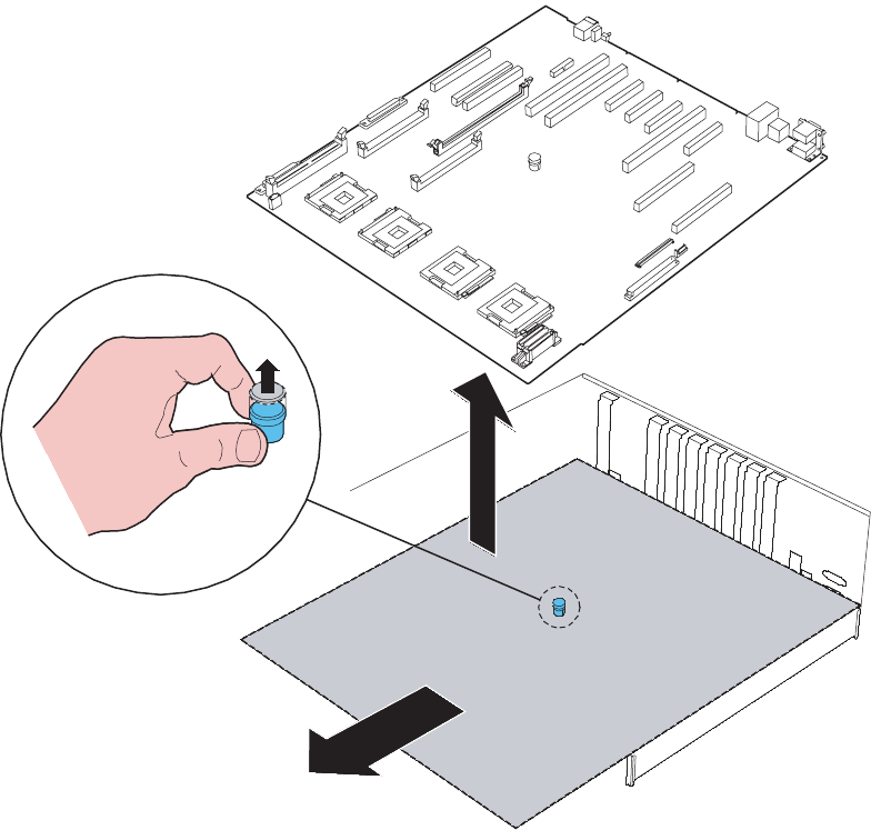
150 www.gateway.com
Chapter 4: Installing Components
13 Lift the blue, spring-loaded plunger in the center of the system board, then slide the
board toward the front of the chassis until it is disengaged.
14 Lift the system board from the chassis and place it in an anti-static bag for storage.
15 Set the new system board into the chassis with the processor sockets toward the front
and the I/O connectors toward the back.
8510702.book Page 150 Thursday, July 7, 2005 11:21 AM
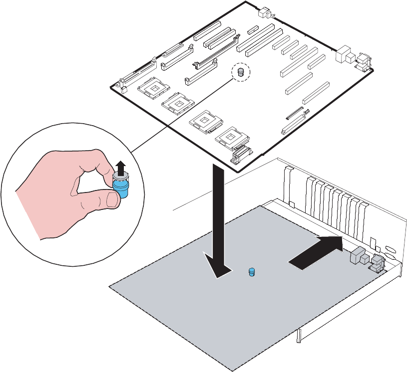
151
www.gateway.com
Replacing the system board
16 Pull up the blue, spring-loaded plunger in the center of the board and slide the board
toward the back of the chassis until the I/O connectors engage the back panel, then
release the plunger.
17 Connect the three-cable bundle from the power distribution board to the power
connectors on the system board (see “System board” on page 5).
18 Connect the chassis intrusion switch cable to the system board.
19 Connect the internal SCSI connector to the system board.
20 Install the plastic PCI dividers onto the system board.
21 Install the center brace by following the instructions in “Removing and installing the
center brace” on page 69.
8510702.book Page 151 Thursday, July 7, 2005 11:21 AM

152 www.gateway.com
Chapter 4: Installing Components
22 Reinstall all PCI expansion cards by following the instructions in “Cold installation
or removal of PCI expansion cards” on page 104.
23 Reinstall the memory boards and memory board air baffles by following the
instructions in “Installing and removing memory boards” on page 85.
24 Reinstall the processor thermal blanks, processors, and heat sinks by following the
instructions in “Installation and removal of processors” on page 111.
25 Reinstall the processor air baffle by following the instructions in “Removing and
installing the processor air baffle” on page 67.
26 Connect any remaining cables to the system board.
27 Follow the instructions in “Closing the server case” on page 72.
28 Turn on your server.
29 Press any key when the Gateway logo screen appears during startup. The System Options
menu opens.
30 Select the BIOS Setup utility, then press ENTER. The BIOS Setup utility opens.
31 Check BIOS settings to make sure that they detect the server’s new hardware, then
save your changes (if any) and close the BIOS Setup utility.
8510702.book Page 152 Thursday, July 7, 2005 11:21 AM

Chapter 5
153
Using the BIOS Setup Utility
• Opening the BIOS Setup utility
• Updating the BIOS
• Resetting the BIOS settings to their factory
defaults
• Resetting the BIOS passwords
8510702.book Page 153 Thursday, July 7, 2005 11:21 AM

154 www.gateway.com
Chapter 5: Using the BIOS Setup Utility
Opening the BIOS Setup utility
The BIOS Setup utility stores basic settings for your server. These settings include basic
hardware configuration, resource settings, and password security. These settings are stored
and saved even when the power is off.
To open the BIOS Setup utility:
1Restart your server.
2At the Gateway Logo screen, press any key to access the System Options menu. The
System Options menu opens.
3Select the BIOS Setup Utility, then press ENTER. The BIOS Setup utility opens.
When you select menu items, the Item Specific Help box on the right side of the screen
displays specific information about the selection. The command bar across the bottom
of the screen shows the keys you press to access help, navigate through the menus,
and perform other tasks.
4Select one of these menus (for a complete list of menu and sub-menu options, see
“BIOS Settings” on page 235):
■Main gives you access to basic information and settings related to your server’s
hardware and configuration.
■Processor gives you access to information and settings related to your server’s
processors.
■Memory gives you access to information and settings related to your server’s
memory configurations.
■Devices gives you access to information and settings related to your server’s built-in
devices.
■Server Management gives you access to settings for system management, console
redirection, event log configuration, and fault-resilient boot settings.
■Security gives you access to settings related to system access passwords and security
options. For more information, see “Server security” on page 39.
■Save, Restore, and Exit gives you access to options for closing the BIOS Setup utility.
Caution
The options in the BIOS Setup utility have been set at the factory for
optimal performance. Changes to these settings will affect the
performance of your server.
Before changing any settings, write them down in case you need to
restore them later. You can record the settings on a printout of “BIOS
Settings” on page 235.
8510702.book Page 154 Thursday, July 7, 2005 11:21 AM

155
www.gateway.com
Updating the BIOS
Updating the BIOS
If you need a new version of the BIOS, you can download the BIOS update from Gateway,
then install the new version from a diskette.
To update the BIOS:
1Print the appendix for BIOS Settings in this guide.
2Download the BIOS update from support.gateway.com.
3Restart your server.
4Access the System Options menu by pressing any key when the Gateway Logo screen
appears during startup.
5Select BIOS Setup Utility from the System Options menu, then press ENTER.
6Record any custom BIOS settings on your printout.
7Follow the instructions in the self-extracting BIOS update file.
8Enter any custom BIOS settings you recorded in Step 6, then save your changes and
close the BIOS Setup utility.
9Follow the instructions in “FRU/SDR Load utility” on page 54.
Rolling BIOS
The BIOS flash memory of this server is divided into two partitions: a primary (active)
partition from which the server boots, and a secondary partition to which BIOS updates
are diverted. When a BIOS update occurs, the existing BIOS image is preserved on the
primary partition and the system is automatically prompted to attempt to boot from the
new BIOS (on the secondary partition). If a boot failure occurs with the new BIOS, the
system will revert to the old BIOS on the other partition.
To manually select the BIOS boot partition:
1Turn off the server, then disconnect the power cords and all other cables connected
to the server.
2Follow the instructions in “Opening the server case” on page 66.
8510702.book Page 155 Thursday, July 7, 2005 11:21 AM

156 www.gateway.com
Chapter 5: Using the BIOS Setup Utility
3Remove the jumper across pins 1-2 of header J8C3 (see the illustration on page 157
for the location of the jumper), then place the jumper across pins 2-3.
4Follow the instructions in “Closing the server case” on page 72.
5Reconnect the power cords and turn on the server. The BIOS is forced to boot from
the primary partition.
After you repair the new BIOS, return the server to the default condition.
6Turn off the server, then disconnect the power cords and all other cables connected
to the server.
7Follow the instructions in “Opening the server case” on page 66.
8Place the jumper back onto pins 1-2.
9Follow the instructions in “Closing the server case” on page 72.
Recovering the BIOS
If you encounter a problem while you are updating the BIOS, such as a power outage, the
BIOS update may not be successful. If the system continues to try to boot from the new,
corrupted BIOS, you can boot the system in recovery mode.
This should only be done if other BIOS recovery methods have failed. In recovery mode
the recovery code will load working BIOS code from the recovery media and use it to boot
to the EFI shell. The minimum number of peripherals will be enabled.
To recover the BIOS:
1Create the BIOS recovery media:
■Create a DOS-bootable USB flash memory device (the recovery media)
■Copy the flash BIOS update application (iflash64.exe) to the root directory of the
recovery media
■Copy the BIOS update file to the root directory of the recovery media
■Edit the autoexec.bat file on the recovery media to automatically run the BIOS
update. For example, add this line to the autoexec.bat file:
iflash64.exe shw4.cap /u /ni
Caution
Moving the jumper while the power is on can damage your server.
Always turn off the server and unplug the power cords and all other
cables before changing the jumper.
8510702.book Page 156 Thursday, July 7, 2005 11:21 AM
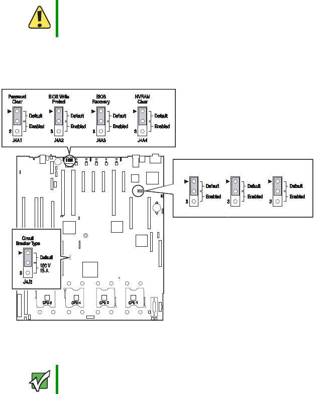
157
www.gateway.com
Updating the BIOS
2Turn off the server, then disconnect the power cords and all other cables connected
to the server.
3Follow the instructions in “Opening the server case” on page 66.
4Remove the jumper across pins 1-2 of jumper J4A3 (the BIOS Recovery jumper), then
place the jumper across pins 2-3.
5Insert the DOS-bootable recovery media into a USB port.
6Reconnect the power cords and turn on the server. The BIOS recovery is initiated.
One beep indicates that the recovery media is valid and that the flash update has
started. The system BIOS initializes the text console and display the progress of the
recovery.
The update will take approximately two minutes and completion will be indicated
by two beeps and a completion message on the screen.
Caution
Moving the jumper while the power is on can damage your server.
Always turn off the server and unplug the power cords and all other
cables before changing the jumper.
Important The new flash BIOS image will not fit on a diskette.
J8C1 J8C2 J8C3
FRB3
Disable
BMC
Reset
FWHID
8510702.book Page 157 Thursday, July 7, 2005 11:21 AM

158 www.gateway.com
Chapter 5: Using the BIOS Setup Utility
7Remove the DOS-bootable recovery media.
8Turn off the server, then disconnect the power cords and all other cables connected
to the server.
9Place the jumper back onto pins 1-2.
10 Follow the instructions in “Closing the server case” on page 72.
11 Plug in the AC power cords and turn on the server, then verify that the recovery was
successful.
Resetting the BIOS
After a successful BIOS update, if one or more applications do not subsequently run you
may want to clear the settings and return to the old BIOS settings. The NVRAM Clear
jumper on the system board (J4A4) lets you return all BIOS settings to the factory defaults.
Your server has three options available to recover the default configuration.
To recover the default BIOS settings using the BIOS Setup utility:
1Restart your server.
2Access the System Options menu by pressing any key when the Gateway logo screen
appears during startup. The System Options menu opens.
3Select BIOS Setup Utility, then press ENTER. The BIOS Setup utility opens.
4From the menu bar, select Save, Restore, & Exit, then click Restore Defaults.
5Press F10 to save the changes and exit, then press Y at the prompt to save the changes.
6The server reboots to the default BIOS settings.
To manually recover the default BIOS settings with jumpers:
1Turn off the server, then disconnect the power cords and all other cables connected
to the server.
2Follow the instructions in “Opening the server case” on page 66.
Caution
Moving the jumper while the power is on can damage your server.
Always turn off the server and unplug the power cords and all other
cables before changing the jumper.
8510702.book Page 158 Thursday, July 7, 2005 11:21 AM
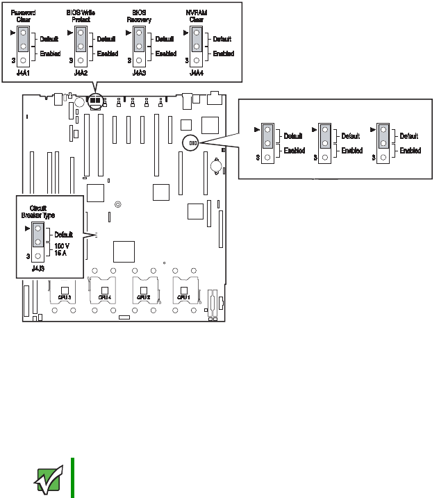
159
www.gateway.com
Updating the BIOS
3Remove the jumper across pins 1-2 of jumper J4A3, then place the jumper across
pins 2-3.
4Follow the instructions in “Closing the server case” on page 72.
5Insert a DOS-bootable CD (SCCD or current SUP CD) into the CD drive or a
DOS-bootable USB disk-on-key containing a valid BIOS image into a USB port. For more
information on creating a current SUP CD, see “Creating a DOS-bootable System
Update Package (SUP) CD” on page 42.
6Reconnect the power cords and turn on the server. The BIOS recovery is initiated.
While the BIOS is being recovered, the monitor displays a blue screen and the server
will beep continually. The process is complete when the server stops beeping.
7Remove the bootable USB disk-on-key or CD.
8Turn off the server, then disconnect the power cords and all other cables connected
to the server.
9Follow the instructions in “Opening the server case” on page 66.
10 Place the jumper back onto pins 1-2.
Important The new flash BIOS image will not fit on a diskette.
J8C1 J8C2 J8C3
FRB3
Disable
BMC
Reset
FWHID
8510702.book Page 159 Thursday, July 7, 2005 11:21 AM

160 www.gateway.com
Chapter 5: Using the BIOS Setup Utility
11 Follow the instructions in “Closing the server case” on page 72.
12 Plug in the AC power cords and turn on the server, then verify that the recovery was
successful.
To recover the default BIOS settings using front control panel buttons:
1Turn off the server, but leave it connected to the AC power source.
2Make sure that the NVRAM Clear jumper (J4A4) is in the default position (Not Clear).
3Hold down the Reset button on the front control panel for at lease 4 seconds.
4While continuing to hold down the Reset button, press the Power button.
5Release both buttons at the same time. The BIOS reverts to the default settings.
Important Check to make sure that the custom settings previously recorded and
entered are not causing the application problems before resetting the
BIOS.
8510702.book Page 160 Thursday, July 7, 2005 11:21 AM
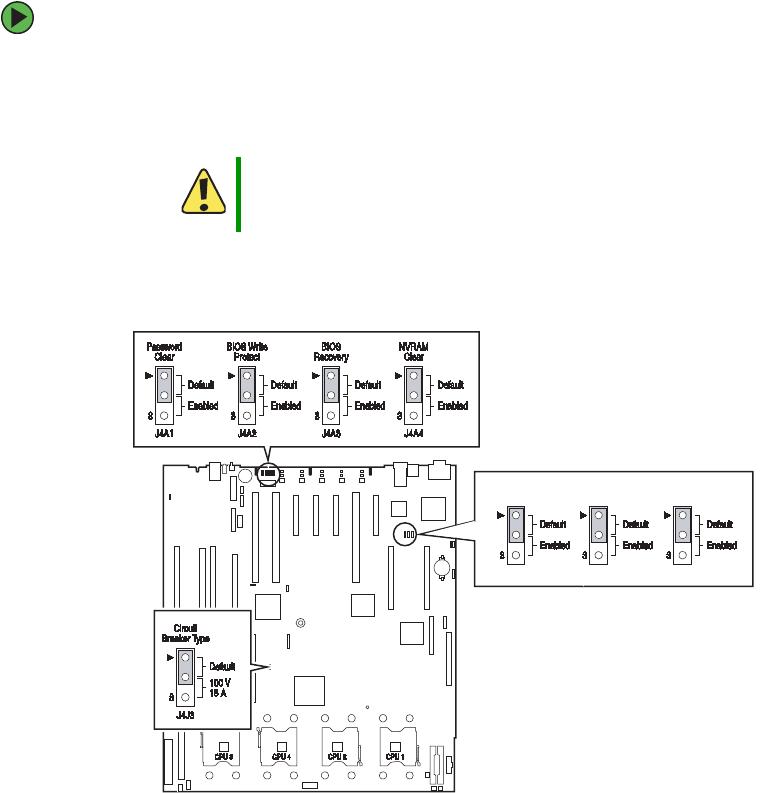
161
www.gateway.com
Updating the BIOS
Resetting BIOS passwords
To reset BIOS password(s), you must either reset and clear all BIOS settings, or use the
Password Clear jumper (J4A1). To clear BIOS settings, follow the instructions in “Resetting
the BIOS” on page 158.
To clear the BIOS passwords using the password clear jumper:
1Turn off the server, then disconnect the power cords and all other cables connected
to the server.
2Follow the instructions in “Opening the server case” on page 66.
3Remove the jumper across pins 1-2 of header J4A1, then place the jumper across
pins 2-3.
4Follow the instructions in “Closing the server case” on page 72.
5Reconnect the power cords and turn on the server. The BIOS password(s) is cleared.
6Turn off the server, then disconnect the power cords and all other cables connected
to the server.
Caution
Moving the jumper while the power is on can damage your server.
Always turn off the server and unplug the power cords and all other
cables before changing the jumper.
J8C1 J8C2 J8C3
FRB3
Disable
BMC
Reset
FWHID
8510702.book Page 161 Thursday, July 7, 2005 11:21 AM


Chapter 6
163
Configuring your RAID
solutions
• Configuring the ROMB RAID solution
8510702.book Page 163 Thursday, July 7, 2005 11:21 AM
164 www.gateway.com
Chapter 6: Configuring your RAID solutions
Introduction
RAID configuration can take place in one of several ways, depending on which RAID
solution(s) you have available on your server. Servers with the optional ROMB RAID
solution can be configured by using either the RAID BIOS Console (text-based)
configuration utility or by using the RAID Web Console (a GUI-based console available
with your browser).
See the section on “Configuring your ROMB RAID solution with the RAID BIOS Console
configuration utility” on page 165, or “Configuring your ROMB RAID solution with the
RAID Web Console” on page 174, depending on how your server is equipped and the
configuration options you prefer.
8510702.book Page 164 Thursday, July 7, 2005 11:21 AM

165
www.gateway.com
Configuring your ROMB RAID solution with the RAID BIOS Console configuration utility
Configuring your ROMB RAID solution
with the RAID BIOS Console
configuration utility
The Intel RAID BIOS Console configuration utilities provide full-featured, HTML-based
configuration and management of optional ROMB RAID arrays. The BIOS Console resides
in firmware and is independent of the operating system. The BIOS Console configuration
utility lets you:
■Choose a configuration method for physical arrays and logical disks
■Create drive arrays
■Define and initialize logical drives
■Access controller, logical drives, and physical arrays to display their properties
■Create hot spare drives
■Rebuild failed drives
■Verify data redundancy in RAID 1, 5, 10, or 50 logical drives
The following table shows the icons found on the top toolbar of the main BIOS Console
configuration screen.
Icon Description
Click on this icon to return to the main screen.
Click on this icon to return to the previous page
Click on this icon to exit the BIOS Console program.
Click on this icon to display the adapters that you can
select.
8510702.book Page 165 Thursday, July 7, 2005 11:21 AM
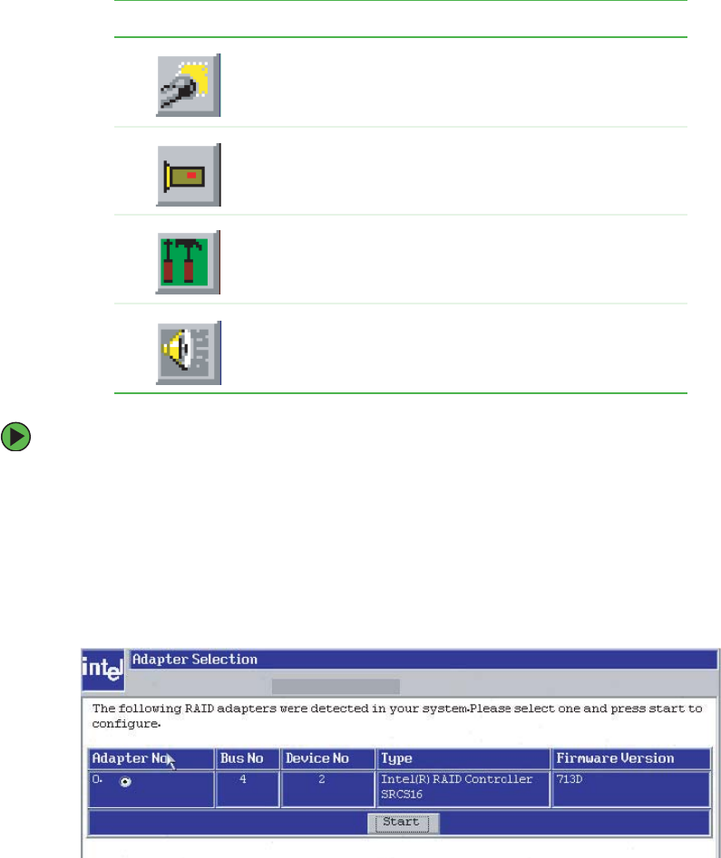
166 www.gateway.com
Chapter 6: Configuring your RAID solutions
To configure your ROMB RAID solution:
1Restart the server.
2When the server reboots, hold the CTRL key and press G when the following message
appears:
Press <Ctrl>-<G> for BIOS Console
The BIOS Console opens at the Adapter Selection screen.
3Select an adapter from the list, then click Start to begin the configuration process.
The Configuration Wizard screen opens.
Click on this icon to scan for adapters connected to your
system.
Click on this icon to display the properties of the adapter,
such as the firmware version, BIOS version, RAM size,
and initiator ID.
Click on the icon to access the Configuration Wizard so
that you can configure the arrays and logical drives.
Click on this icon to silence the sound on the alarm.
Icon Description
8510702.book Page 166 Thursday, July 7, 2005 11:21 AM
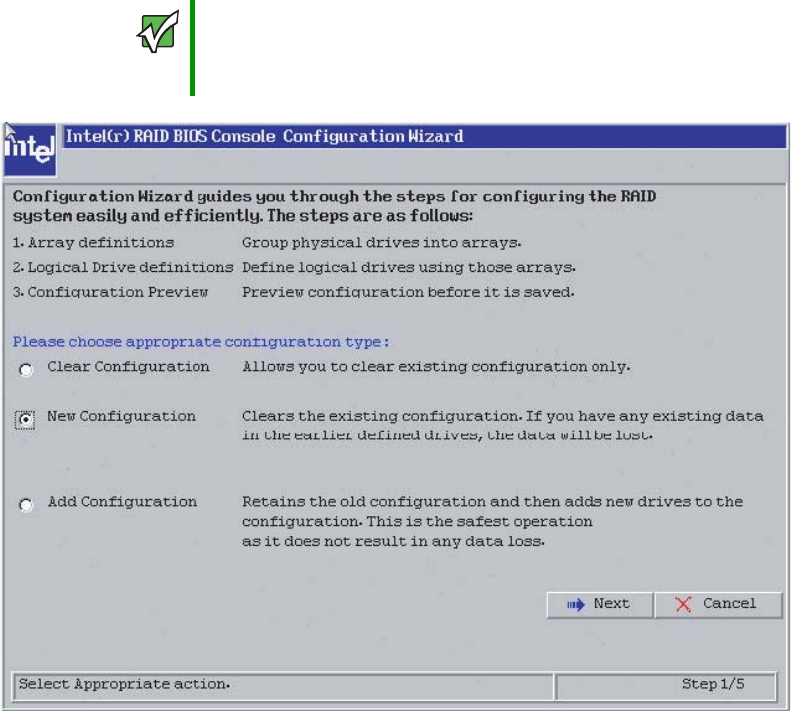
167
www.gateway.com
Configuring your ROMB RAID solution with the RAID BIOS Console configuration utility
4Select the configuration type, then click Next.
5Select the configuration method:
Auto Configuration with Redundancy - This option configures RAID 1 for systems
with 2 drives or RAID 5 for systems with 3 or more drives. All available physical drives
will be included in the logical drive using all available capacity on the disks.
Note: Hot spare drives must be designated before starting auto configuration using
all available capacity on the disks.
Auto Configuration without Redundancy - Configures all available drives as a RAID
0 logical drive.
Custom Configuration - Lets you specify configuration options.
Important If there is a configuration mismatch between the disks and the
NVRAM, the utility automatically displays the Select Configuration
screen. Choose whether the configuration should be read from the
RAID array or from NVRAM.
8510702.book Page 167 Thursday, July 7, 2005 11:21 AM
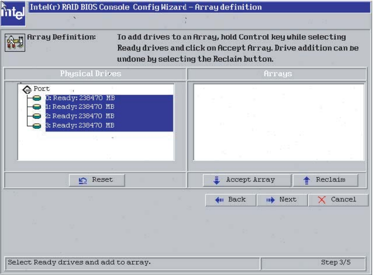
168 www.gateway.com
Chapter 6: Configuring your RAID solutions
6Select Custom Configuration, then click Next. The Array Definition screen opens.
7Hold down the CTRL key and click each drive you want included in the array. To undo
the changes, click Reclaim.
8510702.book Page 168 Thursday, July 7, 2005 11:21 AM
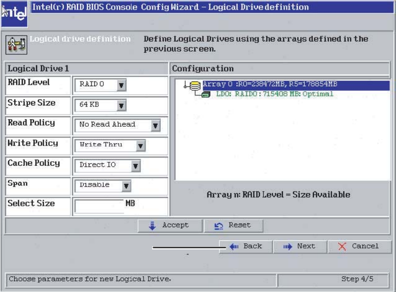
169
www.gateway.com
Configuring your ROMB RAID solution with the RAID BIOS Console configuration utility
8When the drives are defined, click Accept Array, then click Next. The Logical Drive
definition screen opens.
9Select the RAID Level from the list.
10 Select the Stripe Size from the list.
Specify the size of the segment written to each disk in a RAID configuration. You can
set the stripe size to 4, 8, 16, 32, 64, or 128 Kbytes. The default is 64 Kbytes.
11 Select the Read Policy from the list to enable the read-ahead feature for the logical drive.
You can set this parameter to:
■Normal - specifies that the controller does not use read-ahead for the current logical
drive.
■Read-ahead - specifies that additional consecutive stripes are read and buffered into
cache. This option will improve performance for sequential reads.
■Adaptive - specifies that the controller begins using readahead if the two most recent
disk accesses occurred in sequential sectors.
8510702.book Page 169 Thursday, July 7, 2005 11:21 AM

170 www.gateway.com
Chapter 6: Configuring your RAID solutions
12 Select the Write Policy from the list to set the write and cache policies. The write policy
parameter specifies the cache write policy.
You can set the write policy to:
■Write-back caching - the controller sends a data transfer completion signal to the
host when the controller cache receives all the data in a transaction.
■Write-through caching - the controller sends a data transfer completion signal to
the host after the disk subsystem receives all the data in a transaction. Write-through
caching is the default setting. Write-through caching has a data security advantage
over Write-back caching. Write-back caching has a performance advantage over
Write-through caching, but it should only be enabled when the optional battery
backup module is installed.
13 Select the Cache Policy from the list. The cache policy applies to I/O on a specific logical
drive. It does not affect the read ahead cache.
The options are:
■Cached I/O - buffers all reads in cache memory.
■Direct I/O - does not buffer reads in cache memory. When possible, Direct I/O does
not override the cache policy settings. Direct I/O transfers data to cache and the
host concurrently. If the same data block is read again, the host reads it from cache
memory.
14 Select the Span from the list.
Enable or disable the spanning mode for the current logical drive. If spanning is
enabled, the logical drive can occupy space in more than one array. If spanning is
disabled, the logical drive can occupy space in only one array.
For two arrays to be spannable, they must have the same stripe width and must be
consecutively numbered. If these criteria are not met, the utility ignores the Span
setting.
Spanning lets the logical drive stripe across multiple arrays. Using this option enables
the use of RAID 10 and RAID 50.
Caution
Do not use write-back caching for any logical drive in a Novell
NetWare volume.
8510702.book Page 170 Thursday, July 7, 2005 11:21 AM
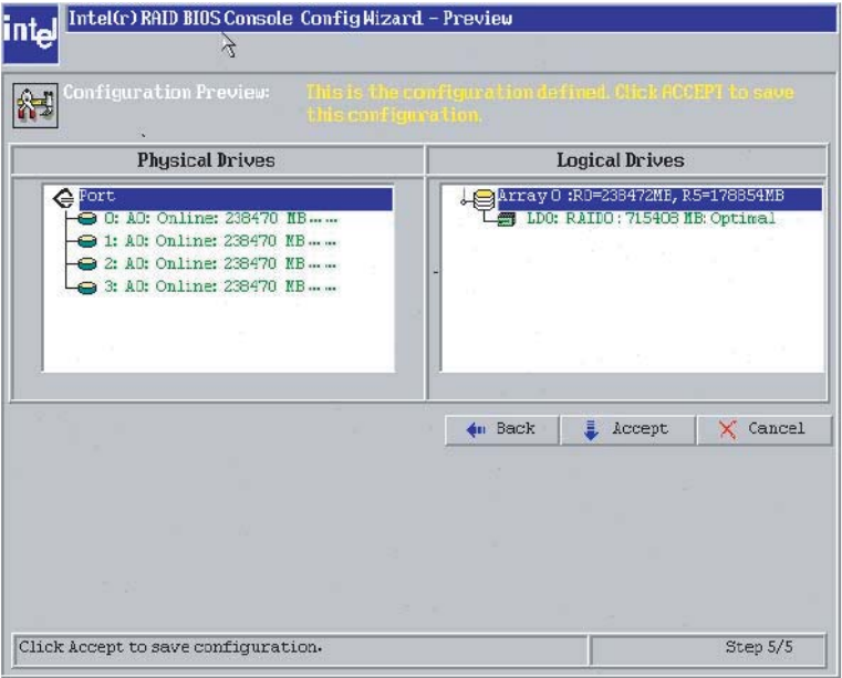
171
www.gateway.com
Configuring your ROMB RAID solution with the RAID BIOS Console configuration utility
RAID 10: To configure a RAID 10 array, create multiple RAID 1 drive arrays
(minimum of two) and enable the span option, then select the size of the logical
drive. It is possible to span as many as eight arrays in a logical drive. When looking
at the logical drive, you will not see a “RAID 10” label, but you will see multiple
arrays in the logical drive representing a RAID 10 configuration.
RAID 50: To configure a RAID 50 array, create multiple RAID 5 drive arrays
(minimum of two) and enable the span option, then select the size of the logical
drive. It is possible to span as many as 8 arrays in a logical drive. When looking
at the logical drive, you will not see a “RAID 50” label, but you will see multiple
arrays in the logical drive representing a RAID 50 configuration.
15 Type the size of the logical drive in the Select Size box.
Set the size of the logical drive in Mbytes. The right pane of the logical drive
configuration window will list the maximum capacity that can be selected, depending
on the RAID level chosen.
16 Click Accept to accept the changes. The console shows you a preview of the
configuration.
8510702.book Page 171 Thursday, July 7, 2005 11:21 AM
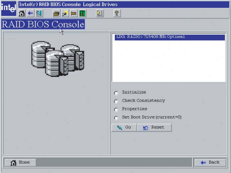
172 www.gateway.com
Chapter 6: Configuring your RAID solutions
17 Click Accept to save the configuration, then click Yes to initialize the logical drive.
The Logical Drives screen opens.
18 Click Initialize to begin the initialization process.
If fast initialization is selected as the default for the adapter properties, a preliminary
initialization will complete within seconds and full initialization will run in the
background after the operating system is booted.
If fast initialization is not selected as the default for the adapter properties, the
initialization may take up to two hours to complete.
8510702.book Page 172 Thursday, July 7, 2005 11:21 AM
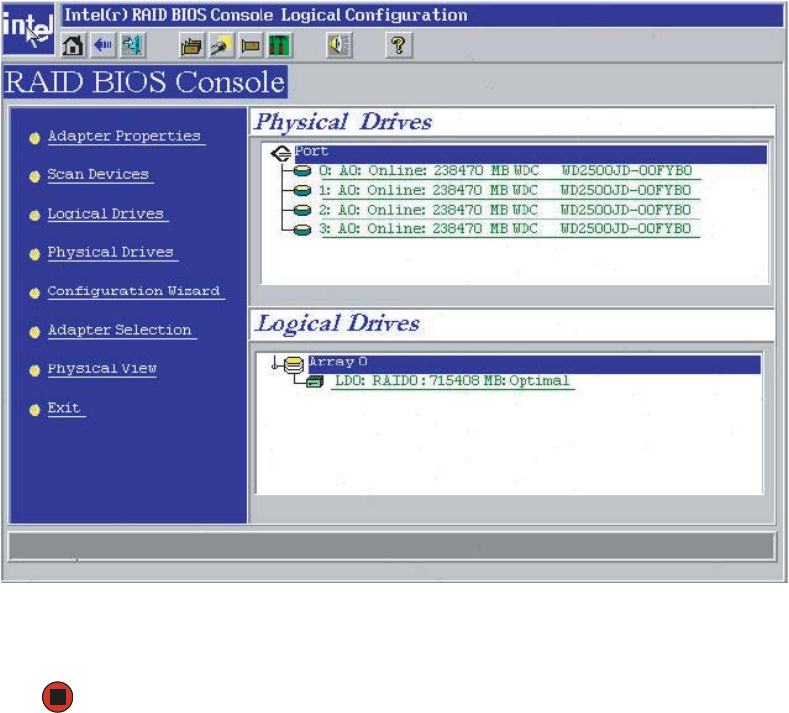
173
www.gateway.com
Configuring your ROMB RAID solution with the RAID BIOS Console configuration utility
19 Click the Home icon on the top menu bar to return to the main configuration screen.
20 Select an additional logical drive to configure or exit the BIOS Console Configuration
Utility and reboot the server.
8510702.book Page 173 Thursday, July 7, 2005 11:21 AM
174 www.gateway.com
Chapter 6: Configuring your RAID solutions
Configuring your ROMB RAID solution
with the RAID Web Console
The Intel RAID Web Console provides full-featured, GUI-based configuration and
management of optional ROMB RAID arrays. The RAID Web Console is accessed by using
your Web browser and is installed as software, specific for your server’s operating system.
The RAID Web Console provides:
■A configuration wizard that guides you through the disk configuration process
■LSI Logic FlexRAID functionality for seamless online expansion without interrupting
server operations
■RAID level migration
■A consistency check to ensure parity and mirrored data accuracy
■A performance monitor
■The ability to change logical drive write, read, and cache policies after the logical drive
configuration
■The ability to save the configuration
■The ability to spin down physical drives before their removal
■The ability to view the current data transfer rate
■Complete system monitoring capabilities
■A RAID event tag
Web Console components
Web Console includes the following software components:
■RAID Web Server, the client support module running on a RAID server that lets you
manage a RAID server remotely from a browser on a client system. It does not require
a locally installed RAID adapter or any specially installed software on the client system
other than a browser. Just point the browser on a client at the address of the RAID
server along with the access port address, then provide a password to enter the
management utility.
■RAID Server is a module that runs on a server configured with a RAID adapter that
provides the connection from the host device (server) to a RAID array (on that server)
and provides the tools to manage the array. It must be installed on each server that
contains a RAID controller in order to manage the RAID configuration from within
an OS (either locally or remotely) through a browser.
8510702.book Page 174 Thursday, July 7, 2005 11:21 AM

175
www.gateway.com
Configuring your ROMB RAID solution with the RAID Web Console
■RAID Registration Server is a module running on a RAID server that tracks RAID servers
on a network. It contains a database of the RAID servers that have registered with it
as RAID servers. RAID servers automatically register with the registration server once
the registration server’s IP address is entered into their RAID server regsrv.dat file.
Client system requirements
The client systems running Web Console must:
■Run Windows XP, Windows 2000 or Windows Server 2003, Linux, NetWare,
OpenServer, or UnixWare (The Windows version of the Web Console is included with
the server. Other versions of the Web Console must be downloaded from
support.gateway.com.
■Utilize a browser that supports Java scripting
■Use a Pentium grade processor or higher CPU
■Have at least 8 Mbytes of system memory
■Have a network interface
■Have at least 5 Mbytes of free hard disk drive space
■Use the TCP/IP protocol
Quick configuration steps
This section provides quick installation steps for users that are familiar with RAID utilities
and tools. See “Configuring arrays and logical drives” on page 187 for detailed
configuration instructions.
The steps to configure arrays and logical drives using the Web Console are:
1Boot the system.
2Install the Java Runtime Environment (JRE).
3Install Web Console.
4Start Web Console.
5Choose a configuration method.
6Designate hot spare disks (optional).
7Create arrays using the available physical drives.
8Define the logical drive(s) using the space in the arrays.
9Initialize the new logical drives.
8510702.book Page 175 Thursday, July 7, 2005 11:21 AM
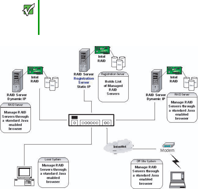
176 www.gateway.com
Chapter 6: Configuring your RAID solutions
Registration server
The Registration server is a RAID server that also has a registration process running on it.
The Registration server maintains a database of all RAID servers in a network, providing
remote management of all available RAID servers through a single point of access. Only
RAID servers can be designated as a registration server. Each RAID server should be
registered with only one registration server.
Important To enable the registration server feature, ensure that the ‘networking’
option is selected during RAID Web Console installation on each
RAID Server. Registration servers must have a static IP address.
RAID servers that are not registration servers may have static or
dynamically configured network addresses.
8510702.book Page 176 Thursday, July 7, 2005 11:21 AM
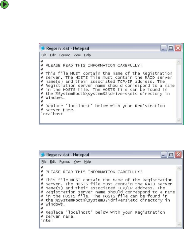
177
www.gateway.com
Configuring your ROMB RAID solution with the RAID Web Console
To enable the registration server:
1Set a static IP address for the registration server.
2On each RAID server to be managed, edit the regserv.dat file located in the etc
directory. Change the localhost entry to the host name of the registration server.
The following edited file shows the localhost entry changed to intel, as an example.
8510702.book Page 177 Thursday, July 7, 2005 11:21 AM
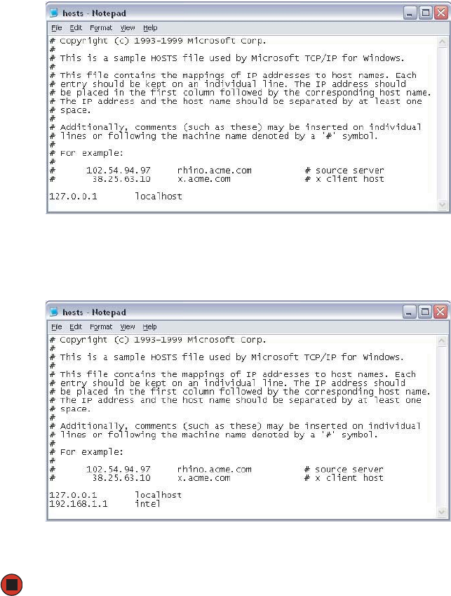
178 www.gateway.com
Chapter 6: Configuring your RAID solutions
3Edit the hosts file on each RAID server to resolve the registration server IP address.
Add the IP address and the host name of the registration server as shown in the
following example.
4Save the file. It will take about two minutes for the change to take effect.
8510702.book Page 178 Thursday, July 7, 2005 11:21 AM
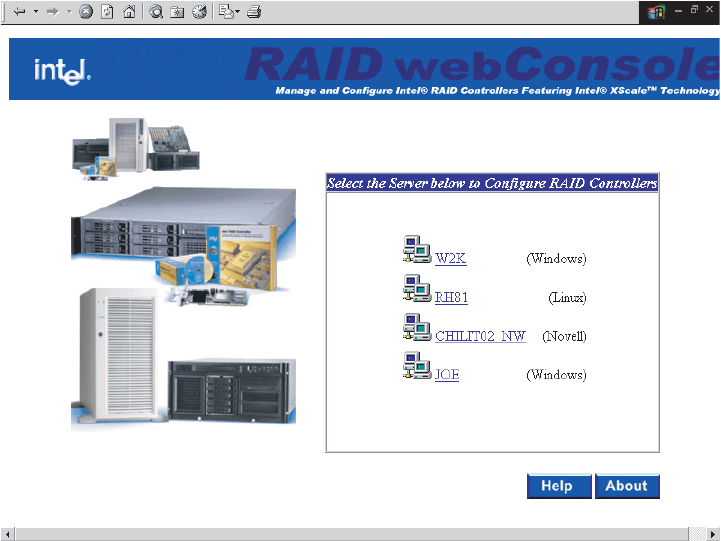
179
www.gateway.com
Configuring your ROMB RAID solution with the RAID Web Console
Registration server operation
When the networking option is enabled in Web Console, the RAID server will look up
the registration server address in the regserv.dat file and resolve it to an IP address through
the hosts file or through DNS resolution. The RAID server will then register its name and
address with the registration server. Each RAID server that is registered with the registration
server will display on the Web Console screen.
A RAID server or a client system that does not have a RAID controller installed can be
used to remotely manage a RAID server through a standard Web browser interface. To do
this, point the browser at the registration server using either the host name or the IP address
of the registration server, such as http://w2k:3570 or http://192.168.1.1:3570.
The Local SetPass utility must be used to set a password on each RAID server. SetPass is
installed as part of the Web Console installation.
8510702.book Page 179 Thursday, July 7, 2005 11:21 AM
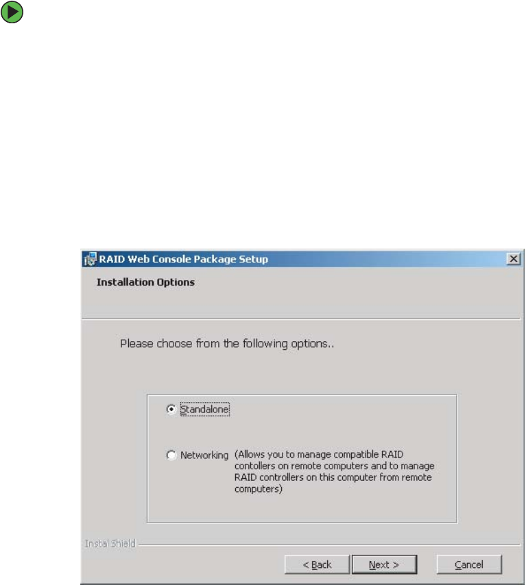
180 www.gateway.com
Chapter 6: Configuring your RAID solutions
Installing the Windows Web Console
To install the Windows Web Console:
1Insert the System Companion CD into the CD drive and double-click on the Install icon
to run the program.
2Click Next. The license agreement and README screens appear.
3Click Next to accept the license agreement and proceed.
4The installation program will first check to verify that the JRE is installed and which
version is installed. If it is not installed or not of the correct version, the installation
program will install the required version of the JRE and then reboot the system.
After reboot, the installation process will continue automatically. The Installation
Options screen opens.
8510702.book Page 180 Thursday, July 7, 2005 11:21 AM
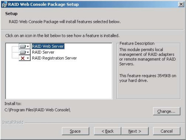
181
www.gateway.com
Configuring your ROMB RAID solution with the RAID Web Console
5Select Standalone or Networking, then click Next. The Setup screen opens.
Choosing Standalone lets the correct modules be installed to support local
management through the Web Console. Select Networking if you want to remotely
manage this or other remote systems.
6Select features to install from the list.
■RAID Web Server - This option provides the Java interface for the RAID Server.
■RAID Server - This option configures the current system as a RAID Server, which
lets it register with the Registration Server for monitoring by the RAID Client. It
also includes the management tools to configure and manage RAID drivers.
■RAID Registration Server - This option configures the current system as the RAID
Registration Server. This option lets other RAID Servers register in the registration
database.
7Select the destination directory path. The default destination directory is C:\Program
Files\RAID Web Console.
8Click on Next to begin installation.
9Set and verify the password. The password can be modified by using the SetPass utility
located at \\programfiles\webconsole\setpass\.
8510702.book Page 181 Thursday, July 7, 2005 11:21 AM

182 www.gateway.com
Chapter 6: Configuring your RAID solutions
10 Edit the REGSERV.DAT and HOSTS.DAT files. The installation retrieves the files for
editing. The REGSERV.DAT file is located at:
C:\winnt\system32\drivers\etc.
The HOSTS.DAT file is located at:
C:\winnt\system32\drivers\etc.
11 Save the file and exit, then reboot your system.
Securing the Web Console under Microsoft Windows XP, Windows 2000, or
Windows Server 2003
After installing the Web Console, you must secure the Web Console for operation. Securing
the Web Console lets only users who are part of the selected groups delete, copy, move,
or execute Web Console files.
To secure the Web Console:
1Log in as the Administrator.
2Run File Manager.
3Select the Web Console path.
4Open the Security menu list in File Manager, then select PERMISSIONS.
5When the Permission dialog box appears, assign the LIST permission to all groups
except Administrator, Backup Operators, System, and Creator Owner.
6In the Permission dialog box, select Replace Permissions On Subdirectories, then click OK.
7Exit File Manager.
8Log in as a guest and verify the permission changes.
8510702.book Page 182 Thursday, July 7, 2005 11:21 AM

183
www.gateway.com
Configuring your ROMB RAID solution with the RAID Web Console
De-registering and re-registering under Web Console
If the registration server fails or shuts down, the other RAID servers or RAID clients must
log back into the registration server after the registration server is online. RAID servers
can register into the registration servers without resetting.
To de-register or re-register in Windows:
1In Windows XP, Windows 2000, and Windows Server 2003, open the control panel.
2Click Administrative Tools, then click Services.
3Click Stop RAID_Server to de-register.
- OR -
Click Start RAID_Server to re-register.
8510702.book Page 183 Thursday, July 7, 2005 11:21 AM
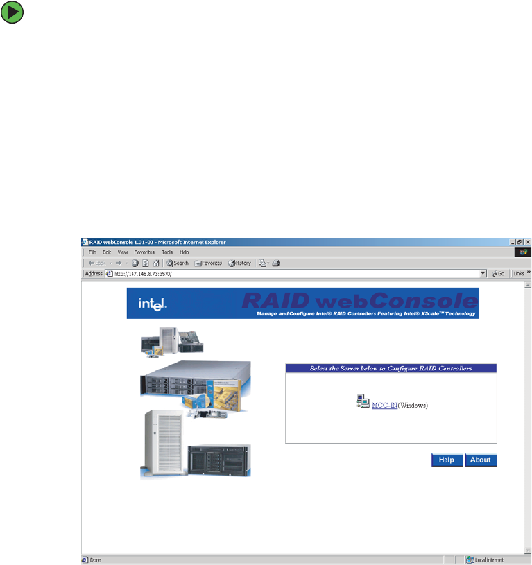
184 www.gateway.com
Chapter 6: Configuring your RAID solutions
Launching the Web Console
Web console is launched from a Web Browser that supports Java scripts. Microsoft Internet
Explorer 5.5 or later and Netscape Browsers are supported.
To launch the Web Console:
1Launch your Web browser and access the RAID controller through port address 3570.
The RAID Web Console initial screen opens.
For Example, for a remote system:
http://192.168.0.1:3570
For local RAID management:
http://localhost:3570
For access to RAID servers listed in the Registration Server Database, use the
registration server’s host name or IP address.
8510702.book Page 184 Thursday, July 7, 2005 11:21 AM
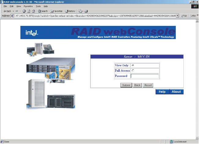
185
www.gateway.com
Launching the Web Console
2Select the RAID controller to be managed by clicking the name of the server in the
window (MCC-IN in this example). The Login screen opens.
You will be presented with an option to control read only functions of the RAID
controller or full access to the RAID controllers configuration options. You must have
the correct rights to manage the RAID controller’s configuration options.
8510702.book Page 185 Thursday, July 7, 2005 11:21 AM
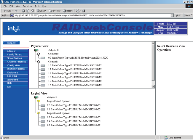

187
www.gateway.com
Launching the Web Console
The following table describes the options available on this screen.
Configuring arrays and logical drives
Automatic RAID configuration
After starting the Configuration Wizard, if you chose one of the auto configuration options,
Web Console displays the proposed RAID configuration in the Logical Devices window.
Each logical drive has a label (such as LD1), RAID level, and drive capacity. Click Accept
to complete the configuration process.
You can delete a logical drive by clicking on it in the bottom config view pane and selecting
Delete from the right config view pane.
Option Description
Adapter This option lets you configure the adapter properties.
Config Wizard This option provides a series of options to let you create
new drive arrays, add capacity to existing arrays, or
modify existing arrays.
Channel
Properties
This option lets you configure the properties of the
available SCSI channels on the RAID controller.
Config View This options lets you switch between the Logical and
Physical drive views.
Device Progress Shows progress of an operation being performed, such
as array initialization.
Enclosure Displays the enclosure status, including its attached
drives.
Log Data This option lets you configure the logged data output.
Advanced This option lets you change the RAID server name, log
data location, and firmware location. It also performs a
firmware update.
Help This option provides the RAID configuration help
screens.
Exit This option lets you exit from the utility and prompts for
reboot.
8510702.book Page 187 Thursday, July 7, 2005 11:21 AM

188 www.gateway.com
Chapter 6: Configuring your RAID solutions
Custom RAID configuration
If you choose Custom Configuration, the Web Console displays the Array Definition screen
with an Arrays pane containing all previously configured arrays. Each logical drive has a
label (such as LD 0), RAID level, and drive capacity. Spanned arrays use hyphenated array
numbers such as LD0-1, which indicates disk drive 1 in array 0.
To create an array:
1Hold down the CTRL key and click the drives you want to add to the array. The selected
drives will be highlighted in blue.
2Click Add to Array. A new logical drive will be displayed in the Arrays pane.
3Click Accept, then Next to continue.
Defining logical drives
After configuring the physical drives, the Logical Drive Parameter screen opens. This screen
displays the logical drive(s) for you to define. You can specify the RAID level and size. You
can also span arrays and set advanced parameters.
The Logical Drive window displays all the arrays on the current adapter and the global hot
spare drive pool. Web Console labels logical drives as New or LD0, LD1, LD2, and so forth.
You must define all the logical drives to be configured in the new array. Do not create
drives that span the current array and another array. Uncheck the Span Array box.
To define logical drives:
1Click the RAID Level from the list. The Wizard does not permit an invalid RAID level
configuration.
2Set the size by accepting the default or by entering a smaller size in the Size box.
Specify a smaller size to leave room in the array for additional logical drives.
Creating multiple logical drives in the same array disables FlexRAID, so you cannot
change RAID levels or add capacity. Do not mix redundant and non-redundant logical
drives in the same array.
3Click Advanced to set the stripe size, read policy, write policy, virtual sizing, and cache
policy. Open each list to display the options for each parameter, select an option, then
click OK to proceed.
If you use Web Console to configure an array on a NetWare server, you cannot use
Writeback as the write policy.
8510702.book Page 188 Thursday, July 7, 2005 11:21 AM

189
www.gateway.com
Launching the Web Console
4Click Accept to save the logical drive.
If space is still available in the current array, the new logical drive appears in the array
and you can define additional logical drives in the current array. The Wizard continues
to create logical drives for the same array until there is no more space available in
the array, or until there are 40 logical drives in the array.
5Open the Span Arrays list to create a logical drive that spans all defined arrays. An
array that encompasses both spanned arrays appears in the Logical Devices window.
Web Console labels the array A[array number]-[disk number]. The capacity in the Size
list increases to reflect the total capacity of the spanned array.
6When you have defined all logical drives for the selected adapter, click Next.
The Preview Configuration screen displays the arrays, logical drives, and hot spares for
the current adapter in the logical devices screen. The Physical Devices window displays
the status of the physical drives.
7Click Finish to accept the displayed configuration. A dialog box prompts you to
initialize. We recommend initializing all newly created logical drives.
To initialize logical drives:
1Select the adapter from the Adapter box.
2Select the logical drives you plan to initialize, then select Initialize from the Logical
Drive menu.
The Initialize screen has a separate window for each logical drive. A bar graph displays
the progress of the initialization. Click Abort if you want to stop the initialization.
3Repeat this process for each adapter in the system.
Important Do not create drives that span the current array and another array.
Uncheck the Span Array box.
Caution
Initializing a logical drive deletes all information on the physical drives
that compose the logical drive.
Important When you are running the Configuration Wizard, you can remove the
most recently created logical drive by clicking Undo.
You cannot undo an array after you finish running the Configuration
Wizard.
8510702.book Page 189 Thursday, July 7, 2005 11:21 AM

190 www.gateway.com
Chapter 6: Configuring your RAID solutions
To check the rebuild rate:
■Select the correct adapter from the Adapter box, then select Rebuild Rate from the
Adapter menu. If there is more than one adapter in the system, click each adapter and
check the rebuild rate. The rebuild rate is not affected when you clear the
configuration.
To Exit the Web Console:
■Select Exit from the Configuration menu to quit the Web Console.
Reclaiming hot spare disks
To reclaim hot spare disks:
■Select the drive and select Remove Hot Spare from the right pane. The Web Console
changes the state of the selected drives to the READY state.
Reconfiguring existing arrays
This section provides instructions for adding and removing physical drives from existing
arrays.
Adding a physical drive to an existing array
To add a physical drive to an array:
1Go to the Config View screen.
2Highlight the logical drive and select properties from the left pane. Select the drive
to add from the Add Physical Drive pane.
8510702.book Page 190 Thursday, July 7, 2005 11:21 AM

191
www.gateway.com
Launching the Web Console
Removing a physical drive from an array
To selectively remove hard drives from an existing array:
1Go to the Config View screen.
2Highlight the logical drive you want to remove, then select Delete from the left pane.
8510702.book Page 191 Thursday, July 7, 2005 11:21 AM

Chapter 7
193
Troubleshooting
• Interpreting error messages and codes
• Troubleshooting
• Getting telephone support and training
If the suggestions in this chapter do not correct the
problem, see “Telephone support” on page 223 for
more information about how to get help.
8510702.book Page 193 Thursday, July 7, 2005 11:21 AM

194 www.gateway.com
Chapter 7: Troubleshooting
Safety guidelines
While troubleshooting your server, follow these safety guidelines:
■Do not attempt to open the monitor. To do so is extremely dangerous. Even if the
power is disconnected, energy stored in the monitor components can be dangerous.
Also, opening the monitor voids its warranty.
■Make sure that you are grounded correctly before opening the server case. For more
information about preventing damage from static electricity, see “Preventing static
electricity discharge” on page 65.
■After you complete any maintenance task where you have to open the server case,
make sure that you close the case, tighten any screws, then reconnect all cables before
you restart your server.
Warning
To avoid bodily injury, do not attempt to troubleshoot your server
problem if:
■Power cords or plugs are damaged
■Liquid has been spilled into your server
■Your server was dropped
■The case was damaged
Instead, unplug your server and contact a qualified computer
technician. If your server was damaged during shipment from
Gateway, contact Gateway Customer Care.
8510702.book Page 194 Thursday, July 7, 2005 11:21 AM
195
www.gateway.com
Error messages
Error messages
These messages often indicate procedural errors such as typing an incorrect keystroke or
trying to save a file to a write-protected diskette. Some messages, however, may indicate
a problem that requires further troubleshooting. These are general messages and do not
represent all possible error messages you might receive.
Diskette drive 0 seek to track 0 failed
■Restart your server, then open the System Options menu by pressing any key while
your server restarts. When the System Options menu opens, select the BIOS Setup
utility, then press ENTER. When the BIOS Setup utility opens, make sure that the drive
settings are correct.
Error loading operating system
■The master boot record may be corrupt. For troubleshooting information, see “The
master boot record is corrupted” on page 219.
Hard disk controller failure
■Make sure that the data cables to the hot swap hard drive cage are connected securely.
■Restart your server, then open the System Options menu by pressing any key while
your server restarts. When the System Options menu opens, select the BIOS Setup
utility, then press ENTER. When the BIOS Setup utility opens, make sure that the correct
drive type is selected.
Hard disk controller failure - press F1 to try reboot
■The drive controller may be defective. Press F1 to try to restart the server. For more
information about running diagnostics on your hard drive, see your operating system’s
documentation.
Insert bootable media device
■Restart your server, then open the System Options menu by pressing any key while
your server restarts. When the System Options menu opens, select the BIOS Setup
utility, then press ENTER. When the BIOS Setup utility opens, make sure that the correct
hard drive is set as the first bootable drive in the Boot menu.
■See “Your server does not recognize a SCSI drive” on page 218 for a possible solution.
Invalid configuration information
■Restart your server, then open the System Options menu by pressing any key while
your server restarts. When the System Options menu opens, select the BIOS Setup
utility, then press ENTER. When the BIOS Setup utility opens, make sure that the
settings are correct.
■Reset the BIOS. For more information, see “Resetting the BIOS” on page 158.
8510702.book Page 195 Thursday, July 7, 2005 11:21 AM
196 www.gateway.com
Chapter 7: Troubleshooting
Invalid partition table
■The master boot record may be corrupt. For troubleshooting information, see “The
master boot record is corrupted” on page 219.
Invalid password
■Enter your password again. Some passwords are case sensitive.
■If you do not know the password, you may need to reinstall the software you are trying
to access.
■System startup passwords are stored in BIOS. If this password has been set and you
do not know it, you may be able to reset the password through system board jumper
settings. For more information, see “Resetting BIOS passwords” on page 161.
Memory errors were detected while the system started up
■See “Memory errors were detected during server start up” on page 219 for a possible
solution.
Memory size error
■Restart your server, then open the System Options menu by pressing any key while
your server restarts. When the System Options menu opens, select the BIOS Setup
utility, then press ENTER. When the BIOS Setup utility opens. Save the memory
configuration.
Missing operating system
■The master boot record may be corrupt. For troubleshooting information, see “The
master boot record is corrupted” on page 219.
System Event Log Full
■Clear the event log. To clear or view the event log, restart your server, then open the
System Options menu by pressing any key. When the System Options menu opens,
select the BIOS Setup utility, then press ENTER. When the BIOS Setup utility opens,
select the Advanced menu, then select the Event Log Control menu.
8510702.book Page 196 Thursday, July 7, 2005 11:21 AM

197
www.gateway.com
Troubleshooting
Troubleshooting
First steps
Try these steps first before going to the following sections:
■Make sure that the power cords are connected to your server and an AC outlet and
that the AC outlet is supplying power.
■If you use a UPS, make sure that it is turned on and is rated to handle the power
required by your server.
■If you added or removed server components before the problem started, review the
installation procedures you performed and make sure that you followed each
instruction. You may need to remove the device, uninstall the device’s software, then
reinstall the device.
■If an error message appears on the screen, write down the exact message before calling
Gateway Customer Care.
■Restart your server, then open the System Options menu by pressing any key while
your server restarts. When the System Options menu opens, select the BIOS Setup
utility, then press ENTER. When the BIOS Setup utility opens, check your configuration
settings.
■If an error occurs in a program, see its documentation or online help.
Battery replacement
If you have problems after installing a new CMOS battery, try each of the following items,
closing the case and restarting the server after each try:
■Restart your server and access the BIOS Setup utility:
Warning
To avoid bodily injury, do not attempt to troubleshoot your server
problem if:
■Power cords or plugs are damaged
■Liquid has been spilled into your server
■Your server was dropped
■The case was damaged
Instead, unplug your server and contact a qualified computer
technician.
8510702.book Page 197 Thursday, July 7, 2005 11:21 AM

198 www.gateway.com
Chapter 7: Troubleshooting
To restart and access the BIOS Setup utility:
1At the Gateway Logo screen, press any key to access the System Options menu.
The System Options menu opens.
2Select the BIOS Setup Utility, then press ENTER. The BIOS Setup utility opens.
3Correct any discrepancies, then save changes and exit.
■Remove the top cover by following the instructions in “Opening the server case” on
page 66, then make sure that all cables inside the case are attached securely. Also, make
sure that the colored cable edges are aligned correctly and that the connectors do not
miss any pins.
■If you have the correct test equipment, make sure that the new battery has power.
Although unlikely, your new battery may be defective.
Warning
To avoid bodily injury, do not attempt to troubleshoot your server
problem if:
■Power cords or plugs are damaged
■Liquid has been spilled into your server
■Your server was dropped
■The case was damaged
Instead, unplug your server and contact a qualified computer
technician.
8510702.book Page 198 Thursday, July 7, 2005 11:21 AM

199
www.gateway.com
Beep codes
Beep codes
Post error beep codes
Whenever a recoverable error occurs during the power-on self-test (POST), the BIOS
displays an error message that describes the problem. The BIOS also sounds a beep code
(one long tone followed by two short tones) during POST if the video configuration fails
(a faulty video controller) or if an expansion card is not functioning correctly. One short
beep indicates the BIOS will boot the operating system. No error found.
A PCI expansion card (for example, a RAID controller) can also issue audible errors by itself,
usually consisting of one long tone followed by a series of short tones. For more
information on the beep codes issued, check the documentation for that device.
The following table shows POST error beep codes. Prior to system video initialization, BIOS
uses these codes to inform users of error conditions.
BIOS recovery beep codes
Beeps Error Message Description
1 Fatal error System halted because of an unspecified
fatal error that was detected.
2 Processor error System halted because a fatal error related
to the processor was detected.
3 Memory error System halted because a fatal error related
to the memory was detected.
4 System board error System halted because a fatal error related
to the system board hardware was detected.
Beeps Error Message POST Progress Code Description
1 Recovery started E9h Start of recovery process
2 Recovery boot error Flashing series of POST
codes: EFh, FAh, FBh,
F4h, FCh, FDh, FFh
Unable to boot to diskette ATAPI,
or ATAPI CD. Recovery process
will retry.
3 Recovery failed FDh Unable to process valid BIOS
recovery images. BIOS already
passed control to operating
system and flash utility.
8510702.book Page 199 Thursday, July 7, 2005 11:21 AM

200 www.gateway.com
Chapter 7: Troubleshooting
Additional beep codes provided by Intel Management
Modules
In addition to the beep codes above, the following additional beep codes are provided by
the Intel Management Module:
4 Recovery complete FFh BIOS recovery succeeded, ready
for power-down and reboot.
Beep Codes Description
1 Control panel CMOS clear has been initiated
1-5-1-1 Processor failure. Reseat or replace the failed processor.
1-5-2-1 No processor is installed or the CPU 1 socket is empty. Reseat or
replace the failed processor.
1-5-2-2 No processors
1-5-2-3 Processor configuration error or CPU 1 socket is empty. Reseat or
replace the failed processor. In a two-processor system, make sure
the processors are identical.
1-5-2-4 Front-side bus select configuration error.
1-5-4-2 DC power unexpectedly lost.
Beeps Error Message POST Progress Code Description
8510702.book Page 200 Thursday, July 7, 2005 11:21 AM

201
www.gateway.com
LED information
LED information
The various subsystems in this server include LEDs that can assist you in troubleshooting
your system. See the following table for a description of these LEDs and the information
they provide:
LED Name Function Location Color Description
Power LED Identify the
power state of
the system
Front panel Green ■Off = Power is off (or S4/S5
with ACPI)
■On = Power is on (or S0 with
ACPI)
■Blinking = S1 Low power
state with ACPI
ID Aid in server
identification
from the back
panel
Front panel and
left back of
system board
Blue On = Server identification
enabled
System
Status/Fault
Visible fault
warning
Front panel Green or
Orange
■On = No fault
■Green blink = Degraded
■Orange blink = Non-critical
■Orange = Critical or
non-recoverable error
Drive status
(general)
Hard drive
activity and fault
status
Front panel Green or
Orange
■Green on = Drive initializing
■Green blink = Drive active
■Orange on = Drive or slot
failure
■Orange slow blink =Drive or
slot fault predicted or rebuild
in progress
■Orange fast blink = Drive
rebuild interrupted or
rebuild on empty slot
Drive status
(individual drives)
Drive activity and
fault status
Individual drive
carriers
Green or
Orange
■Green blink - Drive active
■Green and orange
alternating - Drive is on and
is rebuilding RAID, or is on
and in fault condition
■Orange blink - Drive is off or
in fault condition
■Unlit - Drive is inactive or no
drive installed in carrier
Memory board
LEDs (8)
Identify condition
of memory board
and DIMMs
On top of each
memory board
Green or
Orange
For location and description,
see “Memory” on page 85.
8510702.book Page 201 Thursday, July 7, 2005 11:21 AM

202 www.gateway.com
Chapter 7: Troubleshooting
Diagnostic POST LEDs
The BIOS sends a code (in raw binary) to port 80 prior to each POST task. These codes
are displayed on eight LEDs, located on the system board, which can be read by the user
and can provide troubleshooting information in the event of a system hang during POST.
For the location of these LEDs, see “System board” on page 5.
Power supply
status (3)
Power supply
module status
On each power
supply module
Green and
Orange
Top LED (green) - On means
power is good
Middle LED (orange) - On
means there is a fault
condition in this power supply
module
Bottom LED (green) - On
means that AC power to this
power supply module is OK.
POST Code
diagnostic LEDs
0-7 (LSB, bit1,
bit2, bit3, bit4, bit5,
bit6, MSB) bottom
to top
Display boot 80
POST code
On the left back
of the system
board
Each LED
can be
Off,
Green,
Orange,
or Red
See Post Code Table below
Fan fault Indicate fan
failure
On each
hot-swap fan
Orange On = Fault
LED reference designator Bit Example: Initialize memory
DS7D2 7 (MSB)
0x27
DS7D3 6
DS7D4 5 On
DS7D5 4
DS7D6 3
DS7D1 2 On
DS7D2 1 On
DS7D3 0 (LSB) On
LED Name Function Location Color Description
8510702.book Page 202 Thursday, July 7, 2005 11:21 AM

203
www.gateway.com
LED information
POST progress codes and definitions
The following table shows the current boot progress codes and associated messages, sent
to the POST progress LEDs:
Progress Code Definition
Host Processor
0×10 Power-on initialization of the host processor (Boot Strap
Processor)
0×11 Host processor cache initialization (including AP)
0×12 Starting Application processor initialization
0×13 SMM initialization
Chipset
0×21 Initializing a chipset component
Memory
0×22 Reading configuration data from memory (SPD on DIMM)
0×23 Detecting presence of memory
0×24 Programming timing parameters in the memory controller
0×25 Configuring memory parameters in the memory controller
0×26 Optimizing memory controller settings
0×27 Initializing memory, such as ECC init
0×28 Testing memory
PCI Bus
0×50 Enumerating PCI busses
0×51 Allocating resources to PCI busses
0×52 Hot-plug PCI controller initialization
0×53-0×57 Reserved for PCI bus
USB
0×58 Resetting USB bus
0×59 Reserved for USB devices
ATA/ATAPI/SATA
0×5A Resetting PATA/SATA bus and all devices
8510702.book Page 203 Thursday, July 7, 2005 11:21 AM

204 www.gateway.com
Chapter 7: Troubleshooting
0×5B Reserved for ATA
SMBUS
0×5C Resetting SMBUS
0×5D Reserved for SMBUS
Local Console
0×70 Resetting the video controller (VGA)
0×71 Disabling the video controller (VGA)
0×72 Enabling the video controller (VGA)
Remote Console
0×78 Resetting the console controller
0×79 Disabling the console controller
0×7A Enabling the console controller
Keyboard (PS2* or USB)
0×90 Resetting the keyboard
0×91 Disabling the keyboard
0×92 Detecting the presence of the keyboard
0×93 Enabling the keyboard
0×94 Clearing keyboard input buffer
0×95 Instructing keyboard controller to run Self Test (PS2 only)
Mouse (USB)
0×98 Resetting the mouse
0×99 Detecting the mouse
0×9A Detecting the presence of mouse
0×9B Enabling the mouse
Fixed Media
0×B0 Resetting fixed media device
0×B1 Disabling fixed media device
0×B2 Detecting presence of a fixed media device (like IDE hard drive)
Progress Code Definition
8510702.book Page 204 Thursday, July 7, 2005 11:21 AM

205
www.gateway.com
LED information
0×B3 Enabling/configuring a fixed media device
Removable Media
0×B8 Resetting removable media device
0×B9 Disabling removable media device
0×BA Detecting the presence of a removable media device (like IDE
CD drive)
0×BC Enabling or configuring a removable media device
BDS
0×Dy Trying boot selection y (where y = 0 to F)
PEI Core
0×E0 Started dispatching early initialization modules (PEIM)
0×E2 Initial memory found, configured, and installed correctly
0×E1, 0×E3 Reserved for initialization module use (PEIM)
DXE Core
0×E4 Entered EFI Driver execution phase (DXE)
0×E5 Started dispatching drivers
0×E6 Started connecting drivers
DXE Drivers
0×E7 Waiting for user input
0×E8 Checking password
0×E9 Entering BIOS setup
0×EA Flash update
0×EE Calling Int 19. One beep unless silent boot is enabled
0×EF Unrecoverable Boot failure/S3 resume failure
Runtime Phase/EFI OS Boot
0×F4 Entering sleep state
0×F5 Exiting sleep state
0×F8 OS has requested EFI to close boot services (ExitBootServices
( ) has been called)
Progress Code Definition
8510702.book Page 205 Thursday, July 7, 2005 11:21 AM

206 www.gateway.com
Chapter 7: Troubleshooting
0×F9 OS has switched to virtual address mode (SetVirtualAddressMap
( ) has been called)
0×FA OS has requested the system to reset (ResetSystem ( ) has been
called)
PEIM/Recovery
0×30 Crisis recovery has been initiated because of a user request
0×31 Crisis recovery has been initiated by software (corrupt flash)
0×34 Loading crisis recovery capsule
0×35 Handing off control to the crisis recovery capsule
0×3F Unable to complete crisis recovery
Progress Code Definition
8510702.book Page 206 Thursday, July 7, 2005 11:21 AM

207
www.gateway.com
LED information
POST error messages and handling
The following table lists the error codes, associated messages, the severity of the error and
the system response.
Error
code
Error message Severity Response
0012 CMOS time not set Major Pause
004C Keyboard/Interface error Major Pause
5220 Configuration cleared by jumper Major Pause
5221 Passwords cleared by jumper Major Pause
5222 Configuration cleared by BMC Major Pause
5223 Configuration default loaded Major Pause
0048 Password check failed Major Halt
0141 PCI resource conflict Major Pause
0146 Insufficient memory to shadow PCI ROM Major Pause
8110 Processor 1 internal error (IERR) Minor Warning
8111 Processor 2 internal error (IERR) Minor Warning
8112 Processor 3 internal error (IERR) Minor Warning
8113 Processor 4 internal error (IERR) Minor Warning
8120 Processor 1 thermal trip error Minor Warning
8121 Processor 2 thermal trip error Minor Warning
8122 Processor 3 thermal trip error Minor Warning
8123 Processor 4 thermal trip error Minor Warning
8130 Processor 1 disabled Minor Warning
8131 Processor 2 disabled Minor Warning
8132 Processor 3 disabled Minor Warning
8133 Processor 4 disabled Minor Warning
8140 Processor 1 failed FRB-3 timer Minor Warning
8142 Processor 2 failed FRB-3 timer Minor Warning
8143 Processor 3 failed FRB-3 timer Minor Warning
8510702.book Page 207 Thursday, July 7, 2005 11:21 AM

208 www.gateway.com
Chapter 7: Troubleshooting
8144 Processor 4 failed FRB-3 timer Minor Warning
8160 Unable to apply microcode update to
processor 1
Major Pause
8161 Unable to apply microcode update to
processor 2
Major Pause
8162 Unable to apply microcode update to
processor 3
Major Pause
8163 Unable to apply microcode update to
processor 4
Major Pause
8180 BIOS does not support the current
stepping for processor 1
Major Pause
8181 BIOS does not support the current
stepping for processor 2
Major Pause
8182 BIOS does not support the current
stepping for processor 3
Major Pause
8183 BIOS does not support the current
stepping for processor 4
Major Pause
8190 Watchdog timer failed on last boot Minor Warning
8198 OS boot watchdog timer failure Major Pause
0192 L3 cache size mismatch Major Pause
0193 CPUID, processor stepping are different Major Pause
0194 CPUID, processor family are different Major Pause
0195 Front side bus mismatch Major Pause
0196 CPUID, processor model are different Major Pause
81A0 Intel Management Module firmware and
FRUSDR update required
Major Pause
0197 Processor speeds are mismatched Major Pause
8300 Baseboard Management Controller failed
self test
Major Pause
8306 Front panel controller locked Minor Warning
8305 Hotswap controller failed Major Pause
Error
code
Error message Severity Response
8510702.book Page 208 Thursday, July 7, 2005 11:21 AM

209
www.gateway.com
LED information
84F2 Server management interface failed Major Pause
84F3 Baseboard management controller in
update mode
Major Pause
84F4 Sensor data record empty Major Pause
84FF System event log full Minor Warning
8500 Memory board A - DIMM1A defective Major Pause
8501 Memory board A - DIMM 1B defective Major Pause
8502 Memory board A - DIMM2A defective Major Pause
8503 Memory board A - DIMM2B defective Major Pause
8508 Memory board B - DIMM1A defective Major Pause
8509 Memory board B - DIMM1B defective Major Pause
850A Memory board B - DIMM2A defective Major Pause
850B Memory board B - DIMM2B defective Major Pause
8510 Memory board C - DIMM1A defective Major Pause
8511 Memory board C - DIMM1B defective Major Pause
8512 Memory board C - DIMM2A defective Major Pause
8513 Memory board C - DIMM2B defective Major Pause
8518 Memory board D - DIMM1A defective Major Pause
8519 Memory board D - DIMM1B defective Major Pause
851A Memory board D - DIMM2A defective Major Pause
851B Memory board D - DIMM2B defective Major Pause
8520 Memory board A - DIMM1A not configured Major Pause
8521 Memory board A - DIMM 1B not configured Major Pause
8522 Memory board A - DIMM2A not configured Major Pause
8523 Memory board A - DIMM2B not configured Major Pause
8528 Memory board B - DIMM1A not configured Major Pause
8529 Memory board B - DIMM1B not configured Major Pause
852A Memory board B - DIMM2A not configured Major Pause
Error
code
Error message Severity Response
8510702.book Page 209 Thursday, July 7, 2005 11:21 AM

210 www.gateway.com
Chapter 7: Troubleshooting
852B Memory board B - DIMM2B not configured Major Pause
8530 Memory board C - DIMM1A not configured Major Pause
8531 Memory board C - DIMM1B not configured Major Pause
8532 Memory board C - DIMM2A not configured Major Pause
8533 Memory board C - DIMM2B not configured Major Pause
8538 Memory board D - DIMM1A not configured Major Pause
8539 Memory board D - DIMM1B not configured Major Pause
853A Memory board D - DIMM2A not configured Major Pause
853B Memory board D - DIMM2B not configured Major Pause
8540 Memory board A - DIMM1A disabled Major Pause
8541 Memory board A - DIMM 1B disabled Major Pause
8542 Memory board A - DIMM2A disabled Major Pause
8543 Memory board A - DIMM2B disabled Major Pause
8548 Memory board B - DIMM1A disabled Major Pause
8549 Memory board B - DIMM1B disabled Major Pause
854A Memory board B - DIMM2A disabled Major Pause
854B Memory board B - DIMM2B disabled Major Pause
8550 Memory board C - DIMM1A disabled Major Pause
8551 Memory board C - DIMM1B disabled Major Pause
8552 Memory board C - DIMM2A disabled Major Pause
8553 Memory board C - DIMM2B disabled Major Pause
8558 Memory board D - DIMM1A disabled Major Pause
8559 Memory board D - DIMM1B disabled Major Pause
855A Memory board D - DIMM2A disabled Major Pause
855B Memory board D - DIMM2B disabled Major Pause
8560 Memory board A - DIMM1A mismatch Major Pause
8561 Memory board A - DIMM 1B mismatch Major Pause
Error
code
Error message Severity Response
8510702.book Page 210 Thursday, July 7, 2005 11:21 AM

211
www.gateway.com
LED information
8562 Memory board A - DIMM2A mismatch Major Pause
8563 Memory board A - DIMM2B mismatch Major Pause
8568 Memory board B - DIMM1A mismatch Major Pause
8569 Memory board B - DIMM1B mismatch Major Pause
856A Memory board B - DIMM2A mismatch Major Pause
856B Memory board B - DIMM2B mismatch Major Pause
8570 Memory board C - DIMM1A mismatch Major Pause
8571 Memory board C - DIMM1B mismatch Major Pause
8572 Memory board C - DIMM2A mismatch Major Pause
8573 Memory board C - DIMM2B mismatch Major Pause
8578 Memory board D - DIMM1A mismatch Major Pause
8579 Memory board D - DIMM1B mismatch Major Pause
857A Memory board D - DIMM2A mismatch Major Pause
857B Memory board D - DIMM2B mismatch Major Pause
8580 Memory board A - DIMM1A correctable
ECC error
Major Pause
8581 Memory board A - DIMM 1B correctable
ECC error
Major Pause
8582 Memory board A - DIMM2A correctable
ECC error
Major Pause
8583 Memory board A - DIMM2B correctable
ECC error
Major Pause
8588 Memory board B - DIMM1A correctable
ECC error
Major Pause
8589 Memory board B - DIMM1B correctable
ECC error
Major Pause
858A Memory board B - DIMM2A correctable
ECC error
Major Pause
858B Memory board B - DIMM2B correctable
ECC error
Major Pause
Error
code
Error message Severity Response
8510702.book Page 211 Thursday, July 7, 2005 11:21 AM

212 www.gateway.com
Chapter 7: Troubleshooting
8590 Memory board C - DIMM1A correctable
ECC error
Major Pause
8591 Memory board C - DIMM1B correctable
ECC error
Major Pause
8592 Memory board C - DIMM2A correctable
ECC error
Major Pause
8593 Memory board C - DIMM2B correctable
ECC error
Major Pause
8598 Memory board D - DIMM1A correctable
ECC error
Major Pause
8599 Memory board D - DIMM1B correctable
ECC error
Major Pause
859A Memory board D - DIMM2A correctable
ECC error
Major Pause
859B Memory board D - DIMM2B correctable
ECC error
Major Pause
85A0 Memory board A - DIMM1A uncorrectable
ECC error
Major Pause
85A1 Memory board A - DIMM 1B uncorrectable
ECC error
Major Pause
85A2 Memory board A - DIMM2A uncorrectable
ECC error
Major Pause
85A3 Memory board A - DIMM2B uncorrectable
ECC error
Major Pause
85A8 Memory board B - DIMM1A uncorrectable
ECC error
Major Pause
85A9 Memory board B - DIMM1B uncorrectable
ECC error
Major Pause
85AA Memory board B - DIMM2A uncorrectable
ECC error
Major Pause
85AB Memory board B - DIMM2B uncorrectable
ECC error
Major Pause
85B0 Memory board C - DIMM1A uncorrectable
ECC error
Major Pause
Error
code
Error message Severity Response
8510702.book Page 212 Thursday, July 7, 2005 11:21 AM

213
www.gateway.com
LED information
85B1 Memory board C - DIMM1B uncorrectable
ECC error
Major Pause
85B2 Memory board C - DIMM2A uncorrectable
ECC error
Major Pause
85B3 Memory board C - DIMM2B uncorrectable
ECC error
Major Pause
85B8 Memory board D - DIMM1A uncorrectable
ECC error
Major Pause
85B9 Memory board D - DIMM1B uncorrectable
ECC error
Major Pause
85BA Memory board D - DIMM2A uncorrectable
ECC error
Major Pause
85BB Memory board D - DIMM2B uncorrectable
ECC error
Major Pause
85C0 Memory board A - DIMM1A invalid speed Major Pause
85C1 Memory board A - DIMM 1B invalid speed Major Pause
85C2 Memory board A - DIMM2A invalid speed Major Pause
85C3 Memory board A - DIMM2B invalid speed Major Pause
85C8 Memory board B - DIMM1A invalid speed Major Pause
85C9 Memory board B - DIMM1B invalid speed Major Pause
85CA Memory board B - DIMM2A invalid speed Major Pause
85CB Memory board B - DIMM2B invalid speed Major Pause
85D0 Memory board C - DIMM1A invalid speed Major Pause
85D1 Memory board C - DIMM1B invalid speed Major Pause
85D2 Memory board C - DIMM2A invalid speed Major Pause
85D3 Memory board C - DIMM2B invalid speed Major Pause
85D8 Memory board D - DIMM1A invalid speed Major Pause
85D9 Memory board D - DIMM1B invalid speed Major Pause
85DA Memory board D - DIMM2A invalid speed Major Pause
85DB Memory board D - DIMM2B invalid speed Major Pause
Error
code
Error message Severity Response
8510702.book Page 213 Thursday, July 7, 2005 11:21 AM

214 www.gateway.com
Chapter 7: Troubleshooting
BIOS
The settings in the BIOS Setup utility are not retained
■Replace the CMOS battery. For more information, see “Replacing the CMOS battery”
on page 147.
CD or DVD drive
Your server does not recognize a CD or DVD, or the CD or DVD drive
■Restart your server, then open the BIOS Setup utility by pressing any key when the
Gateway logo appears. When the System Options menu opens, select BIOS Setup utility,
then press ENTER. Make sure that the IDE controllers are enabled. For more
information, see “Using the BIOS Setup Utility” on page 153.
■Reinstall the device driver. For more information, see Using Your System Companion CD.
■Make sure that the drive is configured correctly by following the instructions in the
drive’s documentation.
■Open your server case and make sure that the cables are connected correctly to the
CD or DVD drive and the connector on the hot-swap backplane, system board, or
controller card.
85E0 Memory board A - memory bad or missing Major Pause
85E8 Memory board B - memory bad or missing Major Pause
85F0 Memory board C - memory bad or missing Major Pause
85F8 Memory board D - memory bad or missing Major Pause
85E1 Memory board A - memory not configured Major Pause
85E9 Memory board B - memory not configured Major Pause
85F1 Memory board C - memory not configured Major Pause
85F9 Memory board D - memory not configured Major Pause
85FC System memory bad or missing Major Pause
85FD System memory not configured Major Pause
Error
code
Error message Severity Response
8510702.book Page 214 Thursday, July 7, 2005 11:21 AM

215
www.gateway.com
LED information
Your CD or DVD drive tray does not open
■Press a straightened paper clip wire into the CD or DVD drive’s manual eject hole.
The drive tray opens.
■If this problem happens frequently while the server is turned on, the drive may be
defective.
Diskette drive
The diskette drive is not recognized
■Restart your server.
■Unplug and replug the USB cable from the drive to the server.
■Try plugging the drive into a different computer
The diskette drive LED is lit continuously
■Remove the diskette from the drive. If the light stays on, try restarting your server.
■Unplug and replug the USB cable from the drive to the server.
■Try plugging the drive into a different computer
USB flash memory device
Your server does not detect a USB flash memory device
■Check to see if the USB flash memory device is shown in the Boot Maintenance
Manager.
■Make sure the USB flash memory device is correctly inserted into the USB connector,
then reset the server. Do not remove the USB flash memory device while the server
reboots, then check the boot manager again.
If these suggestions do not work, do the following:
1Create a small FAT partition (less than 64MB) on a system that is running
Windows XP.
2Format the partition as FAT
3Reinstall the USB flash memory device into a USB port on the server, then boot
the server to the DOS disk in the USB diskette drive.
4Use FDISK.EXE to delete all of the partition and create a small partition for DOS.
Make sure the partition is set to active.
5Turn the server off, then back on.
8510702.book Page 215 Thursday, July 7, 2005 11:21 AM

216 www.gateway.com
Chapter 7: Troubleshooting
6Remove all other bootable media from the server.
Your server has problems booting to the USB flash memory device that has a partition
and is formatted correctly
To correct the problem:
1Run FDISK/MBR
2Make sure the partition is active.
3Make sure the partition has been correctly formatted as a bootable partition.
4Use the boot manager to select the boot device.
Your server boots to EFI when trying to boot to a USB diskette drive or to the USB flash
memory device
This typically indicates that no key was pressed when prompted to enter the System
Options menu or that the first boot device is EFI.
To correct the problem:
1At the EFI Shell command prompt, type EXIT to return to the System Options
menu.
2Select Boot Manager from the System Options menu.
3Select the correct boot device from the list.
Important The USB flash memory device will only be present in the boot
manager while it is plugged in. After the USB flash memory device
is removed and the system is rebooted, the USB flash memory device
will no longer be seen in the boot manager.
8510702.book Page 216 Thursday, July 7, 2005 11:21 AM

217
www.gateway.com
LED information
Your server has a SCSI hard drive and a USB flash memory device installed and the
server continues to boot from the SCSI drive
The SCSI hard drive is set as the first Legacy Hard Disk Drive in the Legacy Hard disk drive
order.
To change the boot order:
1Plug the USB flash memory device into a USB port on your server.
2Boot the server.
3When you see the Gateway Logo screen, press any key to access the System
Options menu.
4When the System Options menu opens, use the down arrow key to select Boot
Maintenance Manager, then press ENTER. The Boot Maintenance Manager menu opens.
5Select Boot Options from the menu, then press ENTER.
6Use the down arrow key to highlight Select Legacy Hard Drive Order, then press
ENTER.
7Use the down arrow key to highlight HardDisk Drive #00, then press ENTER.
8Select Apply Changes, then press ENTER.
9Press ESC repeatedly until the Boot Maintenance Manager menu opens.
10 Select Reset System, then press ENTER.
11 After the server has rebooted, access the System Options menu as described in
Step 3.
12 Select Boot Manager and make sure the USB flash memory device is shown as a
selectable boot device, then exit the menu.
Expansion cards
Your server does not recognize an expansion card
■Restart your server.
Important Make sure to document the boot order before it is changed. Also make
sure you have a backup of any data. After you have completed the
tasks with the USB flash memory device, reset the boot order back
to the original configuration.
8510702.book Page 217 Thursday, July 7, 2005 11:21 AM
218 www.gateway.com
Chapter 7: Troubleshooting
■Make sure that you have installed the necessary software or driver. For more
information, see the card’s documentation.
■Reseat the card. For more information, see “PCI expansion cards” on page 98.
■Install the card in a different slot.
Hard drive
The hard drive cannot be accessed, or you receive a “General failure reading drive C”
error message
■If a diskette is in the diskette drive, eject it and restart your server by pressing the
reset button.
■Restart your server by pressing the reset button.
■Open your server and make sure that the cables are connected correctly to the SCSI
hot-swap backplane and the system board. For more information, see “Installing a
hot-swap hard drive” on page 80.
■Check to make sure the drive is fully seated.
■If your server has been subjected to static electricity or physical shock, you may need
to reinstall the operating system.
You receive a “Non-system disk” or “disk error” error message
■Eject the diskette from the diskette drive, then press ENTER.
■Make sure that your hard drive has an active partition. For more information, see “The
master boot record is corrupted” on page 219.
Your server does not recognize a SCSI drive
■Make sure that the SCSI controller is enabled in the BIOS Setup utility.
■Reinstall the device driver. For more information, see Using Your System Companion CD.
■Change the drive’s SCSI address to one that is not being used by your server. For more
information about SCSI device configurations, see your drive’s documentation.
■Run SCSI Verify in the SCSI BIOS. For more information about the SCSI BIOS, see the
SCSI controller’s documentation.
■Make sure that the drive is fully seated. Reseat the drive.
■Open your server and reseat the drive controller card. Also make sure that the
controller card and power cables are connected to the drive. For more information,
see “PCI expansion cards” on page 98 or your controller card’s documentation.
■Make sure that the power cable and SCSI cable are attached securely to the drive cage.
8510702.book Page 218 Thursday, July 7, 2005 11:21 AM

219
www.gateway.com
LED information
■Make sure that the last device on the SCSI cable is correctly terminated. For more
information about SCSI device configurations, see the device’s documentation.
■Use a different SCSI cable.
The master boot record is corrupted
■In a Windows network operating system, repair the master boot record using FDISK.
To repair the master boot record:
■At a DOS command prompt, type fdisk/mbr, then press ENTER.
Internet
You cannot connect to the Internet
■Make sure that your account with your Internet Service Provider (ISP) is set up
correctly. Contact your ISP technical support for help.
Keyboard
Liquid has been spilled into the keyboard
■If you spilled liquid in the keyboard, turn off your server and unplug the keyboard.
Clean the keyboard and turn it upside down to drain it. Let the keyboard dry before
using it again. If the keyboard does not work after it dries, you may need to replace it.
This type of damage is not covered by your server’s warranty.
Memory
Memory errors were detected during server start up
■Open your server and make sure that the memory modules are installed correctly. For
more information, see “Installing and removing DIMMs” on page 91.
■A memory module may be defective. Check the LEDs on all of the memory boards
to make sure no fault LEDs are on. Replace the faulty memory.
8510702.book Page 219 Thursday, July 7, 2005 11:21 AM
220 www.gateway.com
Chapter 7: Troubleshooting
Monitor
Your server has no video and the LED on the control panel indicates that the system is
in reset mode
■Make sure that all the cables, processors, and VRMs are fully seated.
■Possibly a faulty VRM. Replace the VRM(s).
Your server is running but there is no picture
■Adjust the brightness and contrast controls to the center position.
■Make sure that the monitor is plugged in and turned on. If the monitor is turned on,
the power LED should be lit.
■Check the port and cable for bent or damaged pins.
■Check the memory boards for fault LEDs. Replace faulty DIMMs.
■Connect your monitor to another computer, or connect a monitor that you know
works to your server.
The color is not uniform
Make sure that the monitor warms up for at least 30 minutes before making a final
judgment about color uniformity.
Make sure that:
■The monitor is not positioned too close to another monitor, electric fan, or fluorescent
light.
■You demagnetize the screen using the monitor’s degauss feature. For more information
on degauss, see the monitor’s documentation.
A horizontal line or wire is visible across the monitor screen
The monitor may use thin damper wires, located approximately 1/3 of the way from the
upper and lower screen edges, to stabilize the internal aperture grille. These wires are most
obvious when the monitor displays a white background. The aperture grille allows more
light to pass through the screen for brighter colors and greater luminescence. The damper
wire is a critical part of the overall monitor design and does not negatively affect the
monitor’s function.
Power
You press the power button, but the server does not turn on
■If the power button LED is green, the server is turned on, but you may not be seeing
an image on the monitor. For monitor troubleshooting, see “Monitor” on page 220.
8510702.book Page 220 Thursday, July 7, 2005 11:21 AM
221
www.gateway.com
LED information
■If your server is plugged into a UPS, make sure that the UPS is connected securely to
an electrical outlet, turned on, and working correctly. One way to check this is to
plug the server directly into a wall outlet, bypassing the UPS.
■Check the power supply modules on the back of the server. Make sure that the LEDs
all indicate that the power supplies are working and the available AC power is good.
■Open your server and make sure that the power supply cables are connected correctly
to the system board.
When you turn on the server, it makes several short beeps
■The short beeps indicate the server has encountered some type of error. See “Beep
codes” on page 199.
When you turn on the server, it turns off after a short time (with a fault light?)
■There may be a short on one of the boards due to a conductive item touching it. Check
to make sure that a screw or other conductive item has not been dropped into the
system.
■Check to make sure that all memory boards and processors are fully seated.
■Check the connections on all cables.
■Check to make sure that the IMM is fully seated.
■Check to make sure that there are no bent pins on the processors.
When you turn on the server, it does not complete POST
■Check to make sure that all memory boards and processors are fully seated.
■Check the BIOS release notes to make sure that the BIOS supports the stepping and
family of the installed processors.
■Check to make sure that you have populated the memory banks in the correct order
and that you are using the correct type of memory. (See “Memory” on page 85)
■Check to make sure that there are no bent pins on the processors.
Processor
Your server does not recognize a new/additional processor
■Make sure that the processor is fully seated in its socket and that the processor has
no bent pins. The processor should be recognized automatically if it is installed
correctly.
■If you have upgraded your server with an additional processor(s):
8510702.book Page 221 Thursday, July 7, 2005 11:21 AM
222 www.gateway.com
Chapter 7: Troubleshooting
■You may need to reconfigure your operating system so it recognizes the additional
processor. For more information, see your operating system’s documentation.
■Check to make sure you added the additional VRMs required for processors 3 and
4 and that they are fully seated in their sockets. See “Processor VRM requirements”
on page 118.
8510702.book Page 222 Thursday, July 7, 2005 11:21 AM

223
www.gateway.com
Telephone support
Telephone support
Before calling Gateway Customer Care
If you have a technical problem with your server, follow these recommendations before
contacting Gateway Customer Care:
■Make sure that your server is connected correctly to a grounded AC outlet that is
supplying power.
■If a peripheral device, such as a keyboard or mouse, does not appear to work, make
sure that all cables are plugged in securely.
■If you have recently installed hardware or software, make sure that you have installed
it following the instructions provided with it. If you did not purchase the hardware
or software from Gateway, see the manufacturer’s documentation and technical
support resources.
■If you have “how to” questions about using a program, see:
■The program’s online Help
■The program’s documentation
■Your operating system’s documentation
■The software or hardware manufacturer’s Web site
■See “Troubleshooting” on page 197.
■Have your client ID, serial number (located on the back of your server case), and order
number available, along with a detailed description of your issue, including the exact
text of any error messages, and the steps you have taken.
■Make sure that your server is nearby at the time of your call. The technician may have
you follow appropriate troubleshooting steps.
■Consider using Gateway’s Internet Customer Care. Gateway’s Web site has FAQs, tips,
and other technical help. You can also use the Web site to e-mail Customer Care. For
more information, visit Gateway’s Customer Care Web site at support.gateway.com.
8510702.book Page 223 Thursday, July 7, 2005 11:21 AM

224 www.gateway.com
Chapter 7: Troubleshooting
Telephone support
Gateway offers a wide range of customer service, technical support, and information
services.
Telephone numbers
You can access the following services through your telephone to get answers to your
questions:
Tutoring and training
Gateway's Customer Care professionals cannot provide hardware and software training.
Instead, Gateway recommends the following training resources.
Resource Service description How to reach
Gateway
Customer Care
Talk to a Gateway Customer Care representative
about a non-tutorial technical support question.
877-485-1464 (US)(option #6)
800-846-3609 (Canada and
Puerto Rico)
605-232-2191
(all other countries)
Sales,
accounting,
and warranty
Get information about available systems, pricing,
orders, billing statements, warranty service, or
other non-technical issues.
800-846-2000 (US)
888-888-2037 (Canada)
Resource Service description For more information
Gateway
Learning
Libraries
A variety of courses and tutorials are available
on CD. Select from several easy-to-use
learning libraries.
www.gateway.com/training
8510702.book Page 224 Thursday, July 7, 2005 11:21 AM

Appendix A
225
Server Specifications
The following specifications are for the standard
configuration. Your server may contain optional
equipment. All specifications are subject to change.
8510702.book Page 225 Thursday, July 7, 2005 11:21 AM

226 www.gateway.com
Appendix A: Server Specifications
System specifications
Case size 10.5 × 27.8 × 17.6 inches (26.2 × 70.6 × 44.7 cm)
Weight 130 lbs (60 kg) or more (varies by configuration)
Fans 6 hot-swap system fans (speed adjustable) in a redundant (5+1)
configuration
Ports ■USB (5)
■Serial (1)
■VGA (2)
■RJ-45 LAN (2 + 1 SM NIC)
Local Control
Panel
An LCD Local Control Panel is optional
Drives
(removable
media)
Two 5.25” drive bays available (standard).
Optional drives:
■USB diskette drive
■CD-ROM, CD-R, or DVD-ROM
■Ta pe d r i ve
Hard Drives Support for ten hot-swap, Ultra 320 SCSI hard drives
Card sizes Supports full-length, full-height PCI expansion cards
Power supply
modules
Two 1570W power supplies in a redundant (1+1) configuration
Operating
systems
Supports:
■Windows Server 2003 Enterprise x64 Edition
■Windows Server 2003 Enterprise (32-bit): SP1
■Red Hat Enterprise Linux 4 (32-bit and Intel EM64T versions)
■Red Hat Enterprise Linux 3 (for Intel EM64T): Update 4
■Red Hat Enterprise Linux 3 (32-bit): Update 4
■SuSE Linux Enterprise Server 9 (32-bit and Intel EM64T versions):
SP1
■SuSE Linux Enterprise Server 8: SP3
Compatible with:
■Windows NT
Certifications ■FCC Class A
■UL
■cUL
8510702.book Page 226 Thursday, July 7, 2005 11:21 AM

227
www.gateway.com
System board specifications
System board specifications
Processor Four sockets for Intel Xeon MP processors with 1 MB of L2 cache or
as much as 8 MB of L3 cache
Voltage Regulator Modules:
■Embedded VRDs supply core voltage for processors 1 and 2
■Two 10.2LD VRMs supply core voltage for processors 3 and 4
■One 9.1 VRM supplies cache voltage for processors 1 and 2
■One 9.1 VRM supplies cache voltage for processors 3 and 4
Chipset Intel E8500
■Two shared 64-bit Front Side Bus (FSB) interfaces configured for
symmetric multiprocessing
■External Memory Boards (XMB) provide support for 400 MHz DDR2
memory
■Intel IOP332 I/O processor and PXH provide support for PCI-X
■Intel 82801EB I/O Controller Hub 5 (ICH-5)
Memory As many as four hot-plug memory boards (with OS support), with four
DIMM slots per board, support as much as 64 GB total memory
■DDR2-400 ECC registered DDR DIMM modules
■DIMM organization x72 ECC
■240-pin DIMMs (256 MB, 512 MB, 1 GB, 2 GB, or 4 GB only)
PCI device/slot On-board VGA and Gb Ethernet
PCI slots:
■Slot 1 - PCI Express x8 (hot-plug)
■Slot 2 - PCI-X 64-bit/133 MHz (hot-plug)
■Slot 3 - PCI Express x4 (hot-plug)
■Slot 4 - PCI Express x4 (hot-plug)
■Slot 5 - PCI Express x4 (hot-plug)
■Slot 6 - PCI-X 64-bit/100 MHz (not hot-plug)
■Slot 7 - PCI-X 64-bit/100 MHz (not hot-plug)
Video On-board ATI Radeon 7000M embedded video controller with 16 MB
of video RAM, mirrored to both front and back I/O ports, including:
■2D/3D video accelerator
■Dual DAC for multi-panel support
■DVI compliant integrated 165MHz TMDS transmitter
■Resolutions from VGA up to UXGA (1600×1200)
■Integrated high-resolution TV-out (up to 1024×768)
■32-bit PCI host interface
8510702.book Page 227 Thursday, July 7, 2005 11:21 AM

228 www.gateway.com
Appendix A: Server Specifications
RAID Two Serial ATA 150 ports from the ICH5-R supporting entry level RAID
functionality, including Integrated Mirroring and Integrated Striping
(RAID levels 0 and 1).
The LSI Logic 53C1030 supports the LSI logic Integrated Mirroring
Enhanced (IME) and Integrated Striping (IS) technology (RAID levels
0 and 1).
Optional ROMB Activation Key also supports RAID levels 5, 10, and
50 and the following:
■Integrated Intel RAID Controller SROMBU42E through Intel XScale
technology. Includes support for up to 256 MB of unbuffered DDR333
RAID cache (requires Intel RAID Activation Key and either the Intel
Portable Cache Module or one 128 MB DDR333 memory DIMM.
■ROMB battery backup unit support (requires the Intel Portable Cache
Module accessory kit or one 128 MB DDR333 memory DIMM).
LAN On-board Broadcom 5407 Gigabit Ethernet Controller
■10Base-T/100Base-TX/1000Base-T
■PXE support
SCSI ■LSI 53C1030 controller
■Dual-channel Ultra320 SCSI channels with integrated RAID 0/1
support
■64-bit PCI-X 100 MHz interface
■Accessible at back panel
ACPI ACPI compliance
Supports S0, S1, S4, S5
Fibre channel
module support
Optional card is based on Qlogic ISP2322 FC-PCI-X controller
■Dedicated slot on system board
■Two independent 2 GB serial fibre channel ports
■Supports up to 400 MBps sustained fibre channel data transfer rate
Hardware
Monitor
Main logic board sensors:
■Voltage sensors
■Temperature sensors
■Adaptive fan speed control and fan speed detection
8510702.book Page 228 Thursday, July 7, 2005 11:21 AM

229
www.gateway.com
Fibre channel card specifications
Fibre channel card specifications
Bus interface 266 MHz PCI-X
Memory ■1MB SRAM per port
■1MB flash
■4Kb NVRAM
Data rate ■1Gbps or 2Gbps autonegotiation
Topology ■FC-AL
■FC-AL-2
■FC-P2P
■FC-SW (FL_Port and F_Port)
Class of service Class 3 FC
Protocol ■SCSI-FCP
■IP
■FC-TAPE
Buffer credits 3 credits available per port (2,112 byte frame payload)
Ports 2
Media Multi-mode optical
Optics Short wave laser
Connectors LC-style optical connectors that support non-OFC, multi-mode fibre
optic cabling using small form factor optical transceiver modules
8510702.book Page 229 Thursday, July 7, 2005 11:21 AM

230 www.gateway.com
Appendix A: Server Specifications
Environmental specifications
The following specifications identify maximum environmental conditions. At no time
should the server run under conditions which violate these specifications.
Variable Requirements
Temperature Maximum rate of change: 18°F (10°C) per hour
Nonoperating: -40° to 158°F (-40° to 70°C)
Operating: 50° to 95°F (10° to 35°C); derated 0.9°F (0.5°C) for every
1,000 feet (305 meters)
Max BTU/hr. 5100
Altitude -100 to 5000 feet (-30 to 1500 meters)
Humidity Nonoperating: 95% (noncondensing) at 77° to 86° F (25° to 30° C)
Vibration 2.2 Grms, 10 minutes per axis on each of the three axis.
Shock Operating: 2.0 g, 11 msec, ½ sine (100 pulses in each direction, on
each of three axes)
Non-Operating: Trapezoidal, 25 G, two drops on each of six faces
ΔV: 175 inches/sec on bottom face drop, 90 inches/sec on the other
five faces
8510702.book Page 230 Thursday, July 7, 2005 11:21 AM

231
www.gateway.com
Electronic specifications
Electronic specifications
Memory map
Interrupts
The following table reflects a typical configuration, but you can change these interrupts.
Use this information to determine how to program each interrupt. The actual interrupt
map is defined using configuration registers in the ICH5-R (I/O controller). I/O Redirection
Registers in the I/O APIC are provided for each interrupt signal. The signals define hardware
interrupt signal characteristics for APIC messages sent to local APIC(s).
Address Range (hex) Amount Function
0 to 07FFFFh 640 KB DOS region, base system memory
0A0000h to 0BFFFFh 128 KB Video or SMM memory
0C0000h and 0DFFFFh 128 KB Expansion card BIOS and buffer area
0E0000h to 0FFFFFh 128 KB System BIOS
0E0000h to 0EFFFFh 2 MB Extended system BIOS
FC000000h to FFFFFFFFh 64 MB PCI memory space
Interrupt Description
IRQ0 Timer/counter, HPET #0 in legacy
replacement Mode. In APIC mode,
cascade from 8259 controller 1
IRQ1 Keyboard controller
IRQ2 Slave controller INTR output. In APIC
mode Timer/counter, HPET #0
IRQ3 Serial port A
IRQ4 Serial port B
IRQ5 Parallel port
IRQ6 Diskette controller
IRQ8 Real-time clock/HPET#1 in legacy
replacement mode
IRQ9 Generic, Option for SCI
8510702.book Page 231 Thursday, July 7, 2005 11:21 AM

232 www.gateway.com
Appendix A: Server Specifications
IRQ10 Generic, Option for SCI
IRQ11 HPET #2, option for SCSI, TCO
IRQ12 Mouse controller
IRQ13 System interrupt/FERR
IRQ14 Primary ATA, legacy mode
PIRQA USB 1.1 controller 1 and 4
PIRQB Video
PIRQC USB 1.1 controller 3, Native IDE, SATA
PIRQD USB 1.1 controller 2
PIRQE Option for SCI, TCO, HPET #0,1,2
PIRQF Option for SCI, TCO, HPET #0,1,2
PIRQG Option for SCI, TCO, HPET #0,1,2
PIRQH USB 2.0 EHCI controller 1, Option for
SCI, TCO, HPET #0,1,2
Ser IRQ SIO3
Interrupt Description
8510702.book Page 232 Thursday, July 7, 2005 11:21 AM

233
www.gateway.com
Additional specifications
Additional specifications
For more information about your server, such as memory size, hard drive size, and
processor type, visit Gateway’s Support page at support.gateway.com. The Support page also
has links to additional Gateway documentation and detailed specifications for your own
server.
8510702.book Page 233 Thursday, July 7, 2005 11:21 AM

Appendix B
235
BIOS Settings
You can print this appendix, then record your
custom BIOS settings on the printout.
8510702.book Page 235 Thursday, July 7, 2005 11:21 AM

236 www.gateway.com
Appendix B:
To view all BIOS settings:
1Restart your server.
2Open the System Options menu by pressing any key while your server restarts. When
the System Options menu opens, select the BIOS Setup utility, then press ENTER. The
BIOS Setup utility opens.
3Select menus and submenus to display setting information.
BIOS menu BIOS submenu Setting Value
Main
BIOS Version
System Date DAY MM/DD/YYYY
System Time HH:MM:SS
Quiet Boot Enable Enabled
Disabled
POST Error Pause Enabled
Disabled
Processor
Core Frequency
Bus Frequency
Processor Retest Enabled
Disabled
Intel® Hyper-Threading
Enable
Enabled
Disabled
Boot Processor Number
Processor #n
Information Menu
Processor Family
Maximum Frequency
Cache Size
CPUID Register
8510702.book Page 236 Thursday, July 7, 2005 11:21 AM

237
www.gateway.com
Thread
n
Status
Thread
n
Health
Memory
Total Memory
Effective Memory
Memory Boards Installed
Current Configuration
Configure Memory
RAS and
Performance
Hardware Memory Test Enabled
Disabled
Patrol Scrub Enabled
Disabled
Retest All System Memory Enabled
Disabled
Sparing Threshold 1 - 15
RAID Upgrade Gap Disabled
512 MB
1024 MB
1536 MB
2048 MB
2560 MB
3072 MB
3585 MB
4096 MB
Desired Memory
Configuration
Max Performance
Max Compatibility
Mirror
RAID
View Configuration Details Links to View
Configuration Details
sub-menu on page 242.
BIOS menu BIOS submenu Setting Value
8510702.book Page 237 Thursday, July 7, 2005 11:21 AM

238 www.gateway.com
Appendix B:
Set Memory Hotplug in
SRAT table
Yes
No
View and Configure
Memory Board
#(board number)
Board Status Not Installed
Healthy
Using Spare
Disabled
Retest Board Memory Enabled
Disabled
Reserve Rank for Spare Enabled
Disabled
DIMM Labels (link to list
showing DIMMs on board)
Devices
IDE Controller
Enable SATA Controller Enabled
Disabled
Primary Master
Mass Storage
Enable On-board SCSI Enabled
Disabled
RAID Activation Key Installed
Not Installed
LAN
Enable On-board NIC Enabled
Disabled
Enable On-board NIC ROM Enabled
Disabled
NIC 1 MAC Address
NIC 2 MAC Address
BIOS menu BIOS submenu Setting Value
8510702.book Page 238 Thursday, July 7, 2005 11:21 AM

239
www.gateway.com
Video
Enable On-board Video Enabled
Disabled
Hard Disk Write Protect Disabled
Enabled
USB
USB Controller Enable Enabled
Disabled
USB 2.0 Controller Enabled
Disabled
Serial Ports
COM 1 Enable Enabled
Disabled
Address 3F8
2F8
3E8
2E8
IRQ 3
4
PCI
Enable Slot 1 ROM Enabled
Disabled
Enable Slot 2 ROM Enabled
Disabled
Enable Slot 3 ROM Enabled
Disabled
Enable Slot 4 ROM Enabled
Disabled
Enable Slot 5 ROM Enabled
Disabled
Enable Slot 6 ROM Enabled
Disabled
BIOS menu BIOS submenu Setting Value
8510702.book Page 239 Thursday, July 7, 2005 11:21 AM

240 www.gateway.com
Appendix B:
Enable Slot 7 ROM Enabled
Disabled
Enable FC Card ROM Enabled
Disabled
Server
Management
Console
Redirection
COM1 Console Redirection Link to COM1 Console
Redirection sub-menu
on page 243.
FRU Information
Board Part Number
Board Serial Number
System Part Number
System Serial Number
Chassis Part Number
Chassis Serial Number
BMC Device ID
BMC Firmware Revision
BMC Device Revision
PIA Revision
SDR Revision
Hot Swap Controller
LAN Management
LAN Controller
n:
Static IP Enable Enabled
Disabled
Host IP Address
Router IP Address
BIOS menu BIOS submenu Setting Value
8510702.book Page 240 Thursday, July 7, 2005 11:21 AM

241
www.gateway.com
NIC1 MAC Address
SEL Logging
Clear Log Enabled
Disabled
FRB Information
Processor #(n) Information Link to Processor #n
Information sub-menu
on page 236.
FRB-2 Enable Enabled
Disabled
OS WD Timer Enable Enabled
Disabled
OS WD Timer 5 minutes
10 minutes
15 minutes
20 minutes
Server
Management
(cont’d)
WOL Resume from S5 Enabled
Disabled
Security
Administrator Password is
(Installed/Not installed)
Set Admin Password (Set or
clear Admin password)
User Password is
(Installed/Not installed)
Set User Password (Set or
clear User password)
Password On Boot Disabled
Enabled
SDR Revision Varies
Exit
Save Changes and Exit
BIOS menu BIOS submenu Setting Value
8510702.book Page 241 Thursday, July 7, 2005 11:21 AM
242 www.gateway.com
Appendix B:
The following 2nd level submenus are accessed from the submenu indicated in the first
column.
Discard Changes and Exit
Save Changes
Discard Changes
Restore Defaults
Save User Default Values
Restore User Default Values
Caution
Before changing modes, back up array data and delete existing
arrays, if any. Otherwise, loss of data may occur.
After operating system installation with a selected SCSI RAID mode,
only change this mode selection if you are prepared to rebuild the
RAID array. Changing the mode could damage the current operating
system installation on the RAID volume.
BIOS submenu BIOS 2nd level
submenu
Setting Value
Configure
System RAS
and
Performance
Sub-Menu
View Memory
Configuration
Details
Configuration Information on selected
configuration.
Max Effective Size
Min. Effective Size
Configuration Capabilities
Configuration Possible Yes/No
Sparing (possible) Yes/No
Hot Replace (possible) Yes/No
BIOS menu BIOS submenu Setting Value
8510702.book Page 242 Thursday, July 7, 2005 11:21 AM

243
www.gateway.com
Hot Add (possible) Yes/No
Board Interleave
BIOS submenu BIOS 2nd level
submenu
Setting Value
Console
Redirection
Sub-Menu
COM1 Console
Redirection
Enable Slot 1 ROM Enabled
Disabled
Flow Control None
RTS/CTS
XON/XOFF
CTS/RTS + CD
Baud Rate 9600
19.2K
38.4K
57.6K
115.2K
Terminal Type VT100
VT100+
VT-UTF8
PC-ANSI
BIOS submenu BIOS 2nd level
submenu
Setting Value
8510702.book Page 243 Thursday, July 7, 2005 11:21 AM

Appendix C
245
Field Replaceable Unit (FRU)
Kits
• Available FRU kits
8510702.book Page 245 Thursday, July 7, 2005 11:21 AM

246 www.gateway.com
Appendix C: Field Replaceable Unit (FRU) Kits
Available FRU kits
FRU Kit Description
DVD/CD-RW combo kit Slimline 8X DVD/24X CD-RW combo drive. For installation
instructions, see “Installing and removing the CD or DVD drive” on
page 73.
Local control display
(LCD) kit
Local Control Display (LCD) panel. For installation instructions, see
“Removing and installing the control panel” on page 84.
Intel Management
Module Advanced kit
Intel Management Module Advanced board. For installation
instructions, see “Installing an Intel Management Module (IMM)”
on page 124.
Processor kits Each kit contains the following:
■Processor
■eVRM 9.1 processor cache (2nd module)
■eVRM 10.2 processor core (Additional modules)
■Processor heatsink
For installation instructions, see “Installation and removal of
processors” on page 111.
Memory riser board kit 2nd-4th memory board 4 DIMM DDR2. For installation instructions,
see “Installing and removing memory boards” on page 85.
HDD SCSI kits Kits for the following drives are available:
■73GB 10K.7 SCA
■146GB 10K.7 SCA
■300GB 10K.7 SCA
■36GB 15K.4 SCA
■73GB 15K.4 SCA
■146GB 15K.4 SCA
For installation instructions, see “Installing a hot-swap hard drive”
on page 80.
Certance DDS-4 5.25"
TBU kit
The kit contains the following:
■Certance DDS-4 5.25" 20/40 GB black
■DDS-4 TBU Blank media
■TBU cleaning cartridge
■MFG instruction: SCSI cable for TBU kits
For instructions on installing 5.25-inch drives, see “Installing a
fixed, removable-media drive in a 5.25-inch drive bay” on page 77.
8510702.book Page 246 Thursday, July 7, 2005 11:21 AM

247
www.gateway.com
Available FRU kits
Certance DAT-72 5.25"
TBU kit
The kit contains the following:
■Certance DAT-72 5.25"
■36 GB/72 GB blank tape
■TBU cleaning cartridge
■MFG instruction: SCSI cable for TBU kits
For instructions on installing 5.25-inch drives, see “Installing a
fixed, removable-media drive in a 5.25-inch drive bay” on page 77.
Certance DAT-432 5.25"
TBU kit
The kit contains the following:
■Certance DAT-432 5.25"
■36 GB/72 GB blank tape
■TBU cleaning cartridge
■Tape media magazine
■MFG instruction: SCSI cable for TBU kits
For instructions on installing 5.25-inch drives, see “Installing a
fixed, removable-media drive in a 5.25-inch drive bay” on page 77.
Certance DAT-432 5.25"
TBU kit
The kit contains the following:
■Certance LTO-2 HH
■MFG instruction: SCSI cable for TBU kits
For instructions on installing 5.25-inch drives, see “Installing a
fixed, removable-media drive in a 5.25-inch drive bay” on page 77.
20320-R SCSI HBA kit 20320-R SCSI HBA
2973-OEM modem 2973-OEM modem
Fibre channel feature kit Fibre channel board (2 port). For installation instructions, see
“Installing or removing the fibre channel module” on page 108.
Tool-less rack rail and
cable management arm
(CMA) kit
The kit contains the following:
■Tool-less rack rails
■Cable management arm (CMA)
■Instructions included in the kit
Pedestal conversion kit The kit contains the following:
■Rackmount-to-pedestal conversion kit
■Gateway custom bezel - pedestal 9715
For installation instructions, see “Converting to pedestal
configuration” on page 11.
Memory kits Created and managed by Crucial. For installation instructions, see
“Installing and removing DIMMs” on page 91.
FRU Kit Description
8510702.book Page 247 Thursday, July 7, 2005 11:21 AM

248 www.gateway.com
Appendix C: Field Replaceable Unit (FRU) Kits
ROMB feature
256MB-RAM DDR2 kit
The kit contains the following:
■ROMB enable key
■256MB-RAM DDR2 (ECC)
For installation instructions, see “Installing and removing the
ROMB (RAID on Motherboard) activation key and dedicated RAID
memory” on page 126.
ROMB feature
512MB-RAM DDR2 kit
The kit contains the following:
■ROMB enable key
■512MB-RAM DDR2 (ECC)
For installation instructions, see “Installing and removing the
ROMB (RAID on Motherboard) activation key and dedicated RAID
memory” on page 126.
ROMB BBU feature kit RAID smart battery backup unit (BBU). For installation instructions,
see “Installing and removing the Smart Battery” on page 129.
FRU Kit Description
8510702.book Page 248 Thursday, July 7, 2005 11:21 AM

Appendix D
249
Extensible Firmware
Interface (EFI) Shell
8510702.book Page 249 Thursday, July 7, 2005 11:21 AM

250 www.gateway.com
Appendix D:
Introduction
The EFI (Extensible Firmware Interface) Shell is an EFI application that lets other EFI
applications be launched, EFI device drivers be loaded, and operating systems be booted.
The EFI Shell provides an interface between operating systems and platform firmware. The
combination of the EFI Shell and EFI firmware provides an environment that can be
adapted to many hardware configurations.
The help command provides information about all the commands (help -b) or specific
commands (help <command>).
For detailed information about the EFI Shell, its commands, and help in developing
applications within the EFI environment, refer to Intel’s EFI Developer’s Guide at
developer.intel.com/technology/efi.
8510702.book Page 250 Thursday, July 7, 2005 11:21 AM

251
www.gateway.com
Basic EFI Shell commands
Basic EFI Shell commands
The following table shows a set of basic EFI Shell commands used to manage files, the EFI
NVRAM Shell, and boot commands.
Command Description
<drive_name>: Changes drives. For example, entering fs0: and pressing
ENTER changes the drive to the LS-240 drive.
alias [-bdv] [sname] [value] Sets or gets alias settings
attrib [-b] [+/-rhs] [
file
] Views or sets file attributes
bcfg -? Configures boot driver and load options in EFI NVRAM
botmaint Launches Boot Maintenance Manager
break Executes a breakpoint
cd [
path
] Changes the current directory
cls [background color] Clears the screen
comp
file1 file2
Compares two files
connect [-r] [-c] Handle#
½DeviceHandle# DriverHandle#
Binds the EFI driver to a device and starts the driver
cp [-r]
file
[
file
] ... [dest] Copies files and directories, [-r] = recursive
date [
mm/dd/yyy
] Gets or sets the date
dblk device [Lba] [Blocks] Performs a hex dump of Blklo Devices
devices [-b] [-1XXX] Displays devices
devtree [-b] [-d] Displays device tree
dh [-b] [-p prot_id] | [handle] Dumps handle information
disconnect DeviceHandle#
[DriverHandle#] [ChildHandle#]
Disconnects device from driver
dmem [address] [size] [;MMIO] Displays the contents of memory
dmpstore Dumps the variable store
drivers [-b] [-IXXX] Displays drivers
drvcfg [-c] [-IXXX] [-f] [-v] [-s] Invokes the driver configuration protocol
drvdiag [-c] [-IXXX] [-s] [-e] [-m] Invokes the driver diagnostics protocol
8510702.book Page 251 Thursday, July 7, 2005 11:21 AM

252 www.gateway.com
Appendix D:
echo [-on | -off] | [text] Echos text to the standard output device or toggles script
echo
edit [
filename
] Opens the text editor letting you create or edit a file
eficompress infile outfile Compresses an EFI file
Efidecompress infile outfile Decompresses an EFI file
endfor Provides a delimiter for loop constructs (scripts only)
endif Provides a delimiter for IF THEN constructs (scripts only)
for var in <set> Executes one or more commands for each item in a set of
items.
goto label Makes a batch file execution jump to another label
guid [-b] [
sname
] Dumps known guid ids
help [-b] [
internal_command
] Displays help information
hexedit [[-f]FileName|[-d
DiskName Offset Size]|[-m Offset
Size]]
Edits in HEX mode
if [not] condition then Provides conditional constructs (scripts only)
load
driver_name
Loads a driver
loadbmp [-c] [-t] [-i[UGA
Instance]] file
Displays a bitmap file on the screen
loadpcirom romfile Loads a PCI option ROM
Is [-b] [
dir
] [
dir
] ... Obtains directory listings
map [-bdvr] [sname[:]] [handle] Maps
sname
to device path
mem [address] [size] [;MMIO] Dumps Memory or Memory Mapped IO
memmap [-b] Dumps memory map
mkdir
dir
[
dir
] Creates a new directory
mm address [Width] [;Type] [n] Memory Modify: type = Mem, MMIO, IO, PCI, [n] for
non-interactive mode when inside a .nsh file
mode [
col row
] Sets or gets the current graphics mode
mount BlkDevice [sname[:]] Mounts a file system on a block device
mv [src...] [dst] Move one or more files/directories to destination
Command Description
8510702.book Page 252 Thursday, July 7, 2005 11:21 AM

253
www.gateway.com
Basic EFI Shell commands
pause Prompts to quit or continue (scripts only)
pci [
bus_dev
] [
func
] Displays PCI device information
rconnect DeviceHandle#
[DriverHandle# [ChildHandle#]] |
[-r]
Reconnects one or more drivers from a device
reset [
reset_string
] Performs a cold reset
rm
file/dir
[
file/dir
] Removes files or directories
setsize file Sets the size of a new file
stall microseconds Delays for the specified number of microseconds
time [
hh:mm:ss
] Gets or sets the time
type [-a] [-u] [-b]
file
Displays the contents of a file
ver Displays version information
vol fs [volume_label] Sets or displays a volume label
Command Description
8510702.book Page 253 Thursday, July 7, 2005 11:21 AM

Appendix E
255
Safety, Regulatory, and Legal
Information
• Safety information
• Legal and Regulatory Information
8510702.book Page 255 Thursday, July 7, 2005 11:21 AM

256 www.gateway.com
Appendix E: Safety, Regulatory, and Legal Information
Important safety information
Your Gateway system is designed and tested to meet the latest standards for safety of information technology
equipment. However, to ensure safe use of this product, it is important that the safety instructions marked on the
product and in the documentation are followed.
Setting up your system
■Read and follow all instructions marked on the product and in the documentation before you operate your
system. Retain all safety and operating instructions for future use.
■Do not use this product near water or a heat source such as a radiator.
■Set up the system on a stable work surface.
■The product should be operated only from the type of power source indicated on the rating label.
■If your computer has a voltage selector switch, make sure that the switch is in the proper position for your area.
The voltage selector switch is set at the factory to the correct voltage.
■Openings in the computer case are provided for ventilation. Do not block or cover these openings. Make sure
you provide adequate space, at least 6 inches (15 cm), around the system for ventilation when you set up your
work area. Never insert objects of any kind into the computer ventilation openings.
■Some products are equipped with a three-wire power cord to make sure that the product is properly grounded
when in use. The plug on this cord will fit only into a grounding-type outlet. This is a safety feature. If you are
unable to insert the plug into an outlet, contact an electrician to install the appropriate outlet.
■If you use an extension cord with this system, make sure that the total ampere rating on the products plugged
into the extension cord does not exceed the extension cord ampere rating.
■If your system is fitted with a TV Tuner, cable, or satellite receiver card, make sure that the antenna or cable
system is electrically grounded to provide some protection against voltage surges and buildup of static charges.
Care during use
■Do not walk on the power cord or allow anything to rest on it.
■Do not spill anything on the system. The best way to avoid spills is to avoid eating and drinking near your
system.
■Some products have a replaceable CMOS battery on the system board. There is a danger of explosion if the
CMOS battery is replaced incorrectly. Replace the battery with the same or equivalent type recommended by
the manufacturer. Dispose of batteries according to the manufacturer’s instructions.
■When the computer is turned off, a small amount of electrical current still flows through the computer. To
avoid electrical shock, always unplug all power cables and modem cables from the wall outlets before cleaning
the system.
■Unplug the system from the wall outlet and refer servicing to qualified personnel if:
■The power cord or plug is damaged.
■Liquid has been spilled into the system.
■The system does not operate properly when the operating instructions are followed.
■The system was dropped or the cabinet is damaged.
■The system performance changes.
Replacement parts and accessories
Use only replacement parts and accessories recommended by Gateway.
Warning
Always follow these instructions to help guard against personal injury
and damage to your Gateway system.
Warning
This unit has two power supplies. To remove power from all internal
circuitry you must disconnect both power cords.
8510702.book Page 256 Thursday, July 7, 2005 11:21 AM

257
www.gateway.com
Important Do not use Gateway products in areas classified as hazardous
locations. Such areas include patient care areas of medical and
dental facilities, oxygen-laden environments, or industrial facilities.
Warning
To reduce the risk of fire, use only No. 26 AWG or larger
telecommunications line cord.
8510702.book Page 257 Thursday, July 7, 2005 11:21 AM

258 www.gateway.com
Appendix E: Safety, Regulatory, and Legal Information
Regulatory compliance statements
United States of America
Federal Communications Commission (FCC)
Unintentional emitter per FCC Part 15
FCC Part 15 Class A Statement
The server is designated as complying with Class A requirements if it bares the following text on the rating label:
This device complies with Part 15 of the FCC Rules. Operation is subject to the following two conditions:
(1) This device may not cause harmful interference.
(2) This device must accept any interference received, including interference that may cause undesired operation.
This device has been tested and found to comply with the limits for a Class A digital device, pursuant to Part 15
of the FCC rules. These limits are designed to provide reasonable protection against harmful interference in a
commercial installation. This equipment generates, uses, and can radiate radio frequency energy and, if not
installed and used in accordance with the instructions, may cause harmful interference with radio
communications. Operation of this equipment in a residential area is likely to cause harmful interference, in
which case you will be required to correct the interference at your own expense.
Telecommunications per FCC part 68
(applicable to products fitted with USA modems)
Your modem complies with Part 68 of the Federal Communications Commission (FCC) rules. On the computer
or modem card is a label that contains the FCC registration number and Ringer Equivalence Number (REN) for
this device. If requested, this information must be provided to the telephone company.
An FCC-compliant telephone line cord with a modular plug is required for use with this device. The modem is
designed to be connected to the telephone network or premises wiring using a compatible modular jack which is
Part 68-compliant. See installation instructions for details.
The Ringer Equivalence Number (REN) is used to determine the number of devices which may be connected to
the telephone line. Excessive RENs on a telephone line may result in the devices not ringing in response to an
incoming call. In most areas, the sum of RENs should not exceed five (5.0). To be certain of the number of
devices that may be connected to a line, as determined by the total RENs, contact the local telephone company.
If this device causes harm to the telephone network, the telephone company will notify you in advance that
temporary discontinuance of service may be required. The telephone company may request that you disconnect
the equipment until the problem is resolved.
The telephone company may make changes in its facilities, equipment, operations, or procedures that could
affect the operation of this equipment. If this happens, the telephone company will provide advance notice in
order for you to make necessary modifications to maintain uninterrupted service.
This equipment cannot be used on telephone company-provided coin service. Connection to party line service is
subject to state tariffs. Contact the state public utility commission or public service commission for information.
When programming or making test calls to emergency numbers:
■Remain on the line and briefly explain to the dispatcher the reason for the call.
■Perform such activities in the off-peak hours such as early morning or late evenings.
Caution
Changes or modifications not expressly approved by Gateway could
void the FCC compliance and negate your authority to operate the
product.
8510702.book Page 258 Thursday, July 7, 2005 11:21 AM

259
www.gateway.com
The United States Telephone Consumer Protection Act of 1991 makes it unlawful for any person to use a
computer or other electronic device to send any message via a telephone fax machine unless such message
clearly contains, in a margin at the top or bottom of each transmitted page or on the first page of the
transmission, the date and time it is sent, an identification of the business, other entity, or other individual
sending the message, and the telephone number of the sending machine or such business, other entity, or
individual. Refer to your fax communication software documentation for details on how to comply with the
fax-branding requirement.
FCC declaration of conformity
Responsible party:
Gateway Companies, Inc.
610 Gateway Drive, North Sioux City, SD 57049
(605) 232-2000 Fax: (605) 232-2023
Product:
■Gateway E-9715R Server
For unique identification of the product configuration, please submit the 10-digit serial number found on the
product to the responsible party.
This device complies with Part 15 of the FCC Rules. Operation of this product is subject to the following two
conditions: (1) this device may not cause harmful interference, and (2) this device must accept any interference
received, including interference that may cause undesired operation.
Canada
Industry Canada (IC)
Unintentional emitter per ICES-003
This digital apparatus does not exceed the Class A limits for radio noise emissions from digital apparatus as set
out in the radio interference regulations of Industry Canada.
Le présent appareil numérique n’émet pas de bruits radioélectriques dépassant les limites applicables aux
appareils numériques de Classe A prescrites dans le règlement sur le brouillage radioélectrique édicté par
Industrie Canada.
Telecommunications per DOC notice
(for products fitted with an IC-compliant modem)
The Industry Canada label identifies certified equipment. This certification means that the equipment meets
certain telecommunications network protective, operation, and safety requirements. The Department does not
guarantee the equipment will operate to the users’ satisfaction.
Before installing this equipment, users should make sure that it is permissible to be connected to the facilities of
the local telecommunications company. The equipment must also be installed using an acceptable method of
connection. In some cases, the inside wiring associated with a single-line individual service may be extended by
means of a certified connector assembly. The customer should be aware that compliance with the above
conditions may not prevent degradation of service in some situations.
Repairs to certified equipment should be made by an authorized Canadian maintenance facility designated by
the supplier. Any repairs or alterations made by the user to this equipment, or equipment malfunctions, may give
the telecommunications company cause to request the user to disconnect the equipment.
Caution
Changes or modifications not expressly approved by Gateway could
void the FCC compliance and negate your authority to operate the
product.
8510702.book Page 259 Thursday, July 7, 2005 11:21 AM

260 www.gateway.com
Appendix E: Safety, Regulatory, and Legal Information
Users should make sure, for their own protection, that the electrical ground connections of the power utility,
telephone lines, and internal metallic water pipe system, if present, are connected together. This precaution may
be particularly important in rural areas.
The Ringer Equivalence Number (REN) assigned to each terminal device provides an indication of the
maximum number of terminals allowed to be connected to a telephone interface. The termination on an
interface may consist of any combination of devices subject only to the requirement that the sum of the Ringer
Equivalence Numbers of all the devices does not exceed 5.
Warning
To avoid electrical shock or equipment malfunction do not attempt to
make electrical ground connections by yourself. Contact the
appropriate inspection authority or an electrician, as appropriate.
8510702.book Page 260 Thursday, July 7, 2005 11:21 AM

261
www.gateway.com
Laser safety statement
All Gateway systems equipped with CD and DVD drives comply with the appropriate safety standards, including
IEC 825. The laser devices in these components are classified as “Class 1 Laser Products” under a US Department
of Health and Human Services (DHHS) Radiation Performance Standard. Should the unit ever need servicing,
contact an authorized service location.
California Proposition 65 Warning
Warning
Use of controls or adjustments or performance of procedures other
than those specified in this manual may result in hazardous radiation
exposure. To prevent exposure to laser beams, do not try to open the
enclosure of a CD or DVD drive.
Warning
This product contains chemicals, including lead, known to the State
of California to cause cancer and/or birth defects or reproductive
harm.
8510702.book Page 261 Thursday, July 7, 2005 11:21 AM

262 www.gateway.com
Appendix E: Safety, Regulatory, and Legal Information
Environmental information
The product you have purchased contains extracted natural resources that have been used in the manufacturing
process. This product may contain substances known to be hazardous to the environment or to human health.
To prevent releases of harmful substances into the environment and to maximize the use of our natural
resources, Gateway provides the following information on how you can responsibly recycle or
reuse most of the materials in your “end of life” product.
Waste Electrical and Electronic Equipment (commonly known as WEEE) should never be
disposed of in the municipal waste stream (residential garbage collection). The “Crossed-Out
Waste Bin” label affixed to this product is your reminder to dispose of your “end of life”
product properly.
Substances such as glass, plastics, and certain chemical compounds are highly recoverable,
recyclable, and reusable. You can do your part for the environment by following these simple
steps:
■When your electrical or electronic equipment is no longer useful to you, “take it back” to your local or regional
waste collection administration for recycling.
■In some cases, your “end of life” product may be “traded in” for credit towards the purchase of new Gateway
equipment. Call Gateway to see if this program is available in your area.
■If you need further assistance in recycling, reusing, or trading in your “end of life” product, you may contact us
at the Customer Care number listed in your product’s user guide and we will be glad to help you with your
effort.
Finally, we suggest that you practice other environmentally friendly actions by understanding and using the
energy-saving features of this product (where applicable), recycling the inner and outer packaging (including
shipping containers) this product was delivered in, and by disposing of or recycling used batteries properly.
With your help, we can reduce the amount of natural resources needed to produce electrical and electronic
equipment, minimize the use of landfills for the disposal of “end of life” products, and generally improve our
quality of life by ensuring that potentially hazardous substances are not released into the environment and are
disposed of properly.
8510702.book Page 262 Thursday, July 7, 2005 11:21 AM

263
www.gateway.com
Notices
Copyright © 2005 Gateway, Inc.
All Rights Reserved
7565 Irvine Center Drive
Irvine, CA 92618-2930 USA
All Rights Reserved
This publication is protected by copyright and all rights are reserved. No part of it may be reproduced or transmitted by any
means or in any form, without prior consent in writing from Gateway.
The information in this manual has been carefully checked and is believed to be accurate. However, changes are made
periodically. These changes are incorporated in newer publication editions. Gateway may improve and/or change products
described in this publication at any time. Due to continuing system improvements, Gateway is not responsible for inaccurate
information which may appear in this manual. For the latest product updates, consult the Gateway Web site at
www.gateway.com. In no event will Gateway be liable for direct, indirect, special, exemplary, incidental, or consequential
damages resulting from any defect or omission in this manual, even if advised of the possibility of such damages.
In the interest of continued product development, Gateway reserves the right to make improvements in this manual and the
products it describes at any time, without notices or obligation.
Trademark Acknowledgments
1-800-GATEWAY, ActiveCPR, ALR, AnyKey, black-and-white spot design, CrystalScan, Destination, DestiVu, EZ Pad, EZ
Point, Field Mouse, Gateway 2000, Gateway Country, gateway.net, Gateway stylized logo, Perfect Scholar, Solo, TelePath,
Vivitron, stylized “G” design, and “You’ve got a friend in the business” slogan are registered trademarks and black-and-white
spotted box logo, GATEWAY, Gateway Astro, Gateway@Work, Gateway Connected touch pad, Gateway Connected music
player, Gateway Cyber:)Ware, Gateway Education:)Ware, Gateway Flex Case, Gateway Gaming:)Ware, Gateway GoBack,
Gateway Gold, Gateway Learning:)Ware, Gateway Magazine, Gateway Micro Server, Gateway Money:)Ware, Gateway
Music:)Ware, Gateway Networking Solutions, Gateway Online Network (O.N.) solution, Gateway Photo:)Ware, Gateway
Professional PCs, Gateway Profile, Gateway Solo, green stylized GATEWAY, green stylized Gateway logo, Gateway
Teacher:)Ware, Gateway Video:)Ware, HelpSpot, InforManager, Just click it!, Learn@Gateway, Kids BackPack,
SERVE-TO-ORDER, Server Watchdog, SpotShop, Spotshop.com, and Your:)Ware are trademarks of Gateway, Inc. Intel, Intel
Inside logo, and Pentium are registered trademarks and MMX is a trademark of Intel Corporation. Microsoft, MS, MS-DOS,
and Windows are trademarks or registered trademarks of Microsoft Corporation. All other product names mentioned herein
are used for identification purposes only, and may be the trademarks or registered trademarks of their respective companies.
8510702.book Page 263 Thursday, July 7, 2005 11:21 AM
265
www.gateway.com
Index
Numerics
5.25-inch drive
installing 77
location 2
A
accessories
safety precautions 256
additional beep codes 200
administrator password
see supervisor password
available FRU kits 246
B
backplane
installing hot-swap 139
Baseboard Management Controller 45
battery
replacing CMOS battery
see battery
troubleshooting 197
beep codes 199
additional 200
BIOS recovery 199
POST error 199
BIOS
resetting passwords 161
resetting to defaults 158
rolling 155
settings 235
troubleshooting 214
updating 155
BIOS recovery beep codes 199
BIOS Setup utility
menus 154, 236
navigating through 154
opening 154
passwords 39, 161
recording configuration 59
settings 236
submenus 242, 243
troubleshooting 214
BMC 45
board
front panel 143
boot
device 18
menu 18
booting from SUP CD 43
C
card
reseating 98
retention levers 3
slot location 5, 98
troubleshooting 217
cardsadd-in card
see card
case
closing 72
interior 4
opening 66
CD
System Companion 58
troubleshooting 214
CD or DVD drive
installing 77
location 2
troubleshooting 214
center brace
installing 69
removing 69
cleaning
keyboard 61
screen 61
servers 60
tape drive 61
closing
case 72
CMOS battery 147
codes
beep 199
POST progress 203
configuring
ROMB RAID 165, 174
connections
8510702.book Page 265 Thursday, July 7, 2005 11:21 AM
266 www.gateway.com
fans 5
keyboard 3
LAN 3
lock slot 3
monitor 3
mouse 3
network 3
parallel 3
power 3
RJ-45 3
serial 3
USB 2, 3
VGA 3
control panel 2
LCD 36
location 2
converting to pedestal configuration 11
cover panel
removing 66
replacing 72
cover release latch
location 2
creating DOS-bootable CD 42
creating SUP CD 42
D
DDR SDRAM
see memory
device drivers
installing 58
Devices menu
BIOS Setup utility 154
diagnostic LEDs
POST progress codes 203
diagnostic POST LEDs 202
DIMM
see memory
diskette drive
installing 77
location 2
replacing 77
troubleshooting 215
display
troubleshooting 220
documentation
Gateway Web site 7
System Companion CD 58
drive bays
location 2
drivers
installing 58
drives
CD 2, 77
configuring 73
diskette 2, 77
DVD 2
hard drive 80
hot-swap 3, 80
installing 73
installing 5.25-inch 77
installing CD 77
installing diskette 77
installing hard drive 80
installing hot-swap 80
installing RAID 80
installing SCSI 80
RAID 3, 80
replacing 73
SCSI 3, 80
tape 61
troubleshooting 214, 215, 218
DVD drive
see CD or DVD drive
E
EFI Shell 249
electronic specifications 231
electrostatic discharge (ESD) 65
Embedded Web Server 50
environmental specifications 230
error messages 195
POST 207
Exit menu
BIOS Setup utility 154
expansion card
see card
F
fans
location 3
rear 3
fibre channel module 106, 108
8510702.book Page 266 Thursday, July 7, 2005 11:21 AM
267
www.gateway.com
installing 108
installing driver 107
fibre channel software 108
front panel board 143
installing 143
FRU kits
available 246
FRU/SDR load utility 54
G
Gateway 7
Customer Care 223
Learning Libraries 224
Web address 7
Gateway Server Manager 36
H
hard drive
indicator 2
LED indicator 2
troubleshooting 218
heat sink
installing 111
help
telephone support 223
tutoring 224
hot swap
memory 87
hot-swap
backplane 139
cage 139, 143
hard drives 3, 80
power supply module 134
hot-swap drive cage
removing 139
hot-swap drives
installing 80
location 2
hot-swap fans
installing 145
I
IDE
drive configuration 73
IMM
installing 124
indicators 2
control panel 2
LED 17
information, LED 201
installing
5.25-inch drive 77
add-in card 98
card 98
CD or DVD drive 77
center brace 69
CMOS battery 147
DIMMs 91
diskette drive 77
fibre channel module 108
front panel board 143
heat sink 111
hot-swap backplane 139
hot-swap cage 139, 143
hot-swap drive 80
hot-swap fans 145
hot-swap hard drive 80
Intel Management Module (IMM) 124
media drive 77
memory boards 85
PCI card 98
PCI expansion cards 98
power distribution module 136
power supply module 134
processor 111
processor air baffle 67
RAID drive 80
SCSI backplane 139, 143
SCSI drive 80
system board 149
tape drive 77
Intel Management Module 124
interior
case 4
Internet connection
troubleshooting 219
interrupts 231
IRQ assignments 231
J
jacks
see connections
8510702.book Page 267 Thursday, July 7, 2005 11:21 AM
268 www.gateway.com
K
Kensington lock slot 3
keyboard
cleaning 61
port 3
troubleshooting 219
L
LAN jack 3
LCD control panel 36
LED
diagnostic 202
indicators 2, 17
information 201
power/sleep 17
line conditioners 15
local control panel 36
lock
Kensington 3
key 2
location 2, 3
M
Main menu
BIOS Setup utility 154
maintenance
cleaning 60
cleaning case 60
cleaning keyboard 61
cleaning screen 61
Gateway Server Manager 36
general guidelines 60
recording BIOS configuration 59
master boot record 219
Memory
installing 91
memory
hot replacement 87
hot swap 87
map 231
mirroring 97
RAID 96
sparing 95
troubleshooting 219
memory boards
cold add 86
cold replacement 86
hot add 85
hot replacement 85
installing 85
Memory menu
BIOS Setup utility 154
memory mirroring 97
memory RAID 96
memory sparing 95
messages 195
mirroring
memory 97
module
fibre channel 106
power distribution 136
monitor
cleaning 61
port 3
troubleshooting 220
motherboard
see system board
mouse port 3
N
network jack 3
O
opening case 66
operating system
setting up 25
P
panel
control 2
LCD 36
local control 36
parallel port 3
password
resetting BIOS 161
supervisor 39
user 39
PCI expansion card
installing 98
removal 98
see card
pedestal 11
8510702.book Page 268 Thursday, July 7, 2005 11:21 AM
269
www.gateway.com
ports
see connections
POST
error messages 207
POST (power-on self-test) 19
POST error beep codes 199
POST progress codes
diagnostic LEDS 203
power
button 2, 16, 24
cord connector 3
indicator 2, 17
LED 2
line conditioners 15
protecting from surges 15
reset button 2
source problems 15
static electricity 65
surge protectors 15
troubleshooting 220
uninterruptible power supply (UPS) 15
power distribution module
installing 136
power supply
uninterruptible 15
power supply module
installing 134
power/sleep LED 17
power-on self-test 19
processor
heat sink 111, 114
installing 111
location 5
replacing 111
troubleshooting 221
processor air baffle
installing 67
removing 67
Processor menu
BIOS Setup utility 154
R
rack mount kit 10
rack mounting server 10
RAID
memory 96
RAID BIOS console 165
RAID cage 139, 143
RAID configuration
RAID BIOS console 165
ROMB 165
Web console 174
RAID drives
installing 80
location 3
RAID Web Console 174
RAM
see memory
see memory boards
rear fan 3
removing 108
fibre channel module 108
see installing
replacing
see installing
reset button 2
resources
interrupts 231
memory map 231
Restore menu
BIOS Setup utility 154
RJ-45 jack 3
rolling BIOS 155
ROMB RAID
configuring 165, 174
S
safety
general precautions 10, 256
guidelines for troubleshooting 194
static electricity 65
Save menu
BIOS Setup utility 154
screen
cleaning 61
troubleshooting 220
SCSI
ID 80
installing drives 80
SDRAM
see memory
security
8510702.book Page 269 Thursday, July 7, 2005 11:21 AM
270 www.gateway.com
setting passwords 39
setting up in BIOS 39
supervisor password 39
system 39
user passwords 39
using password 39
Security menu
BIOS Setup utility 154
SEL viewer utility 55
serial number 223
serial port 3
server
mounting 10
Server menu
BIOS Setup utility 154
setting up
hardware 10
operating system 25
safety precautions 10, 60, 256
settings
torque 64
Setup utility
see BIOS Setup utility
Shell
EFI 249
slots
card 5
processor 5
software
fibre channel 108
sparing
memory 95
specifications 225
electronic 231
environmental 230
system board 227
starting server 16
static electricity 65
SUP CD
booting from 43
creating 42
supervisor password 39
surge protector 15
system 226
administration 36
control 36
ID indicator 41
management 36
security 39
specifications 226
startup 16
system board
components 5
installing 149
replacing 149
specifications 227
thumbscrew location 3
System Companion CD 7, 58
system configuration
protecting with passwords 39
system interrupts 231
system recovery
recording BIOS configuration 59
T
tape drive
cleaning 61
technical support
Customer Care 223
resources 223
tips before contacting 223
telephone support 223
torque settings 64
training
CD 224
Gateway Learning Libraries 224
troubleshooting
add-in card 217
battery 197
beep codes 199
BIOS 214
card 217
CD drive 214
CD or DVD 214
diagnostic POST LEDs 202
diskette drive 215
error messages 195
expansion card 217
general guidelines 197
general safety guidelines 194
hard drive 218
Internet connection 219
8510702.book Page 270 Thursday, July 7, 2005 11:21 AM
271
www.gateway.com
keyboard 219
LED information 201
master boot record 219
memory 219
monitor 220
power 220
power source problems 15
processor 221
safety guidelines 194
SCSI drive 218
technical support 223
telephone support 223
USB flash memory device 215
video 220
turning off server 24
turning on server 16
U
uninterruptible power supply (UPS) 15
updating BIOS 155
UPS 15
USB ports 2
location 2, 3
user password 39
utility
FRU/SDR Load 54
SEL viewer 55
V
VGA port 3
W
Web console
components 174
quick configuration steps 175
registration server 176
Web site
Gateway 7
8510702.book Page 271 Thursday, July 7, 2005 11:21 AM
272 www.gateway.com
8510702.book Page 272 Thursday, July 7, 2005 11:21 AM

MAN 9715 SRV USR GDE R0 06/05
