Gateway Unmanaged Ethernet Switch Users Manual User's Guide
Unmanaged Ethernet Switch to the manual b44df6f8-463e-44dd-9253-302b9121a9a7
2015-02-05
: Gateway Gateway-Unmanaged-Ethernet-Switch-Users-Manual-403410 gateway-unmanaged-ethernet-switch-users-manual-403410 gateway pdf
Open the PDF directly: View PDF ![]() .
.
Page Count: 44
- Contents
- Introduction
- Installation
- Connecting the Switch
- Specifications
- Safety, Regulatory, and Legal Information
- Index

User Guide
Gateway Unmanaged Ethernet Switch
i
Contents
1 Introduction. . . . . . . . . . . . . . . . . . . . . . . . . . . . . . . . . . . . . . . . . . . . . . . . . . . . . . 1
Gigabit Ethernet technology . . . . . . . . . . . . . . . . . . . . . . . . . . . . . . . . . . . . . . . . . . . 2
Switching technology . . . . . . . . . . . . . . . . . . . . . . . . . . . . . . . . . . . . . . . . . . . . . . . . . 2
Switch descriptions . . . . . . . . . . . . . . . . . . . . . . . . . . . . . . . . . . . . . . . . . . . . . . . . . . 3
Features . . . . . . . . . . . . . . . . . . . . . . . . . . . . . . . . . . . . . . . . . . . . . . . . . . . . . . . 3
Front-panel components . . . . . . . . . . . . . . . . . . . . . . . . . . . . . . . . . . . . . . . . . . . 4
LED Indicators . . . . . . . . . . . . . . . . . . . . . . . . . . . . . . . . . . . . . . . . . . . . . . . . . . . 6
Rear panel description . . . . . . . . . . . . . . . . . . . . . . . . . . . . . . . . . . . . . . . . . . . . 7
Side panel description . . . . . . . . . . . . . . . . . . . . . . . . . . . . . . . . . . . . . . . . . . . . 8
2 Installation . . . . . . . . . . . . . . . . . . . . . . . . . . . . . . . . . . . . . . . . . . . . . . . . . . . . . . . 9
Before you connect to the network . . . . . . . . . . . . . . . . . . . . . . . . . . . . . . . . . . . . . 10
Installing the 5- and 8-port switches . . . . . . . . . . . . . . . . . . . . . . . . . . . . . . . . . . . . 11
Package contents . . . . . . . . . . . . . . . . . . . . . . . . . . . . . . . . . . . . . . . . . . . . . . . 11
Attaching the rubber feet . . . . . . . . . . . . . . . . . . . . . . . . . . . . . . . . . . . . . . . . . 11
Provide for adequate ventilation . . . . . . . . . . . . . . . . . . . . . . . . . . . . . . . . . . . . 11
Power on . . . . . . . . . . . . . . . . . . . . . . . . . . . . . . . . . . . . . . . . . . . . . . . . . . . . . . 11
Power failure . . . . . . . . . . . . . . . . . . . . . . . . . . . . . . . . . . . . . . . . . . . . . . . . . . . 12
Installing the 16- and 24-port switches . . . . . . . . . . . . . . . . . . . . . . . . . . . . . . . . . . 13
Package contents . . . . . . . . . . . . . . . . . . . . . . . . . . . . . . . . . . . . . . . . . . . . . . . 13
Installing the 16- and 24-port switches without a rack . . . . . . . . . . . . . . . . . . . 13
Installing the 16- and 24-port switches in a rack . . . . . . . . . . . . . . . . . . . . . . . 14
Power on . . . . . . . . . . . . . . . . . . . . . . . . . . . . . . . . . . . . . . . . . . . . . . . . . . . . . . 15
Power failure . . . . . . . . . . . . . . . . . . . . . . . . . . . . . . . . . . . . . . . . . . . . . . . . . . . 15
3 Connecting the Switch. . . . . . . . . . . . . . . . . . . . . . . . . . . . . . . . . . . . . . . . . . 17
Connecting to an end node . . . . . . . . . . . . . . . . . . . . . . . . . . . . . . . . . . . . . . . . . . . 18
Connecting to a hub or switch . . . . . . . . . . . . . . . . . . . . . . . . . . . . . . . . . . . . . . . . 19
Connecting to a network backbone or server . . . . . . . . . . . . . . . . . . . . . . . . . . . . . 20
A Specifications. . . . . . . . . . . . . . . . . . . . . . . . . . . . . . . . . . . . . . . . . . . . . . . . . . . 21
Gateway 7401-24 (24-port), gigabit Ethernet switch . . . . . . . . . . . . . . . . . . . . 22
Gateway 7401-05 (5-port), and 7401-08 (8-port) gigabit Ethernet switches . . 24
Gateway 7201-16 (16-port), and 7201-24 (24-port), fast Ethernet switches . . 26
Gateway 7201-24.2 (24-port), fast Ethernet switch + 2GTP switch . . . . . . . . 28

1
1
Introduction
This chapter provides you with an introduction to several
Gateway unmanaged switches. Read this chapter to learn
about:
■Gigabit Ethernet technology
■Switching technology
■Switch descriptions
■Features
■Front panel components
■LED indicators
■Rear panel descriptions
■Side panel descriptions
2
Chapter 1: Introduction
www.gateway.com
Gigabit Ethernet technology
Gigabit Ethernet is an extension of IEEE 802.3 Ethernet. It uses the same packet
structure, format, and support for CSMA/CD protocol, full duplex, and flow
control, but with a tenfold increase in theoretical throughput over 100-Mbps
Fast Ethernet and a hundredfold increase over 10-Mbps Ethernet. Because it is
compatible with all 10-Mbps and 100-Mbps Ethernet environments, Gigabit
Ethernet provides a straightforward upgrade without wasting a company’s
existing investment in hardware, software, and trained personnel.
The increased speed and extra bandwidth offered by Gigabit Ethernet are
essential to coping with the network bottlenecks that frequently develop as
computers and their busses get faster and more users use applications that
generate more traffic. Upgrading key components, such as your backbone and
servers, to Gigabit Ethernet can greatly improve network response times as well
as significantly speed up the traffic between your subnets.
Gigabit Ethernet supports video conferencing, complex imaging, and similar
data-intensive applications.
Because data transfers occur 10 times faster than Fast Ethernet, servers outfitted
with Gigabit Ethernet NIC’s are able to perform 10 times the number of
operations in the same amount of time.
Switching technology
Another key development pushing the limits of Ethernet technology is in the
field of switching technology. A switch bridges Ethernet packets at the MAC
address level of the Ethernet protocol transmitting among connected Ethernet
or Fast Ethernet LAN segments.
Switching is a cost-effective way of increasing the total network capacity
available to users on a local area network. A switch increases capacity and
decreases network loading by making it possible for a local area network to be
divided into different segments which do not compete with each other for
network transmission capacity, giving a decreased load on each.
The switch acts as a high-speed selective bridge between the individual
segments. Traffic that needs to go from one segment to another (from one port
to another) is automatically forwarded by the switch, without interfering with
any other segments (ports). This allows the total network capacity to be
multiplied, while still maintaining the same network cabling and adapter cards.
3
Switch descriptions
www.gateway.com
For Fast Ethernet or Gigabit Ethernet networks, a switch is an effective way of
eliminating problems of chaining hubs beyond the “two-repeater limit.” A
switch can be used to split parts of the network into different collision domains,
for example, making it possible to expand your Fast Ethernet network beyond
the 205-meter network diameter limit for 100BASE-TX networks. Switches
supporting both traditional 10Mbps Ethernet and 100Mbps Fast Ethernet are
also ideal for bridging between existing 10Mbps networks and new 100Mbps
networks.
Switching LAN technology is an improvement over the previous generation of
network bridges, which were characterized by higher latencies. Routers have
also been used to segment local area networks, but the cost of a router and the
setup and maintenance required make routers relatively impractical. Today’s
switches are an ideal solution to most kinds of local area network congestion
problems.
Switch descriptions
These unmanaged switches were designed for easy installation and high
performance in an environment where traffic on the network and the number
of users increase continuously.
Features
■16 or 24 10/100Mbps Fast Ethernet ports. (Gateway 7201-16 or 7201-24)
■5, 8, or 24 10/100/1000Mbps Gigabit Ethernet ports. (Gateway 7401-05,
7401-08, and 7401-24 switches)
■24 10/100Mbps + 2Gps Ethernet ports (Gateway 7201-24.2)
■Supports Auto-Negotiation for speed and duplex mode.
■Supports Auto-MDIX for each port.
■Full-/half-duplex transfer mode for 10Mbps and 100Mbps.
■Full-duplex transfer mode for 1000Mbps.
■Store-and-Forward switching method.
■IEEE 802.3x flow control for full-duplex mode.
■Backpressure flow control for half-duplex mode.
■Integrated address Look-Up Engine, supports 4K absolute MAC addresses.
4
Chapter 1: Introduction
www.gateway.com
■Supports 2M bits data buffer per device.
■Front-panel indicator LEDs.
Front-panel components
The front panels of the switches consist of LED indicators and fast Ethernet or
gigabit Ethernet ports. The number of LEDs, and the number and speed of the
ports, depends on the switch model selected.
Comprehensive LED indicators display the status of the switches and the
network.
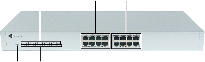
Gateway 7201-16 (shown) and 7201-24 fast Ethernet switches
Speed LEDs
Link/Act
LEDs
Power
LED
Ports 1-8 Ports 9-16
Fast Ethernet
5
Switch descriptions
www.gateway.com
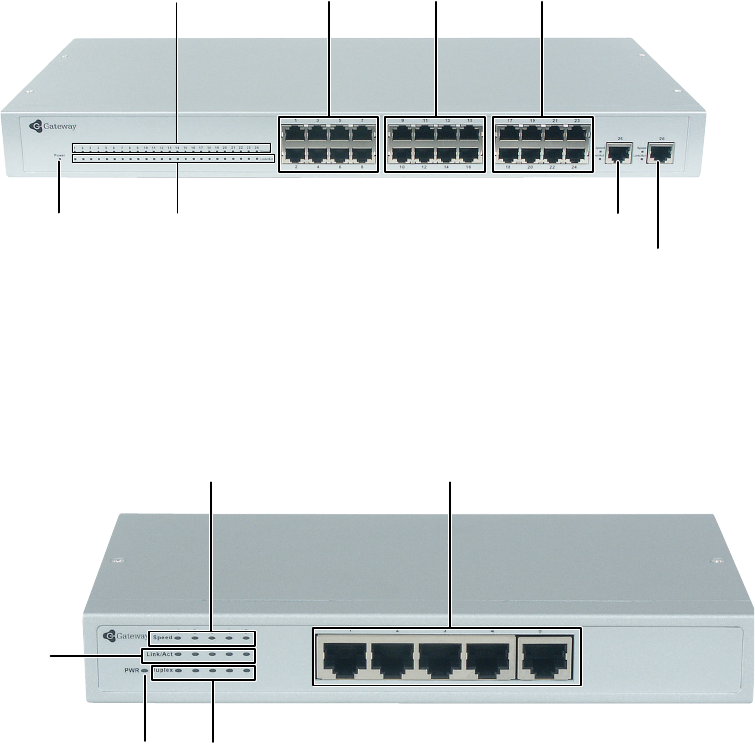
Gateway 7201-24.2 fast Ethernet/gigabit Ethernet switch
Gateway 7401-05 (shown) and 7401-08 gigabit Ethernet switches
Speed LEDs
Link/Act
LEDs
Power
LED
Ports 1-8 Ports 9-16
Fast Ethernet
Ports 17-24
Port 25 and LEDs
Port 26 and LEDs
Gigabit Ethernet
Speed LEDs
Link/Act
LEDs
Power
LED
Ports 1-5
Gigabit Ethernet
Duplex LEDs
6
Chapter 1: Introduction
www.gateway.com
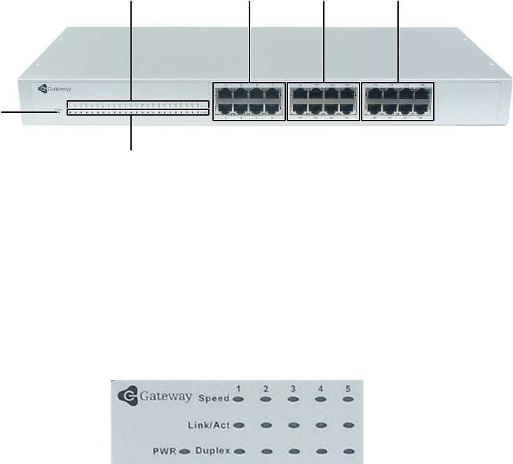
Gateway 7401-24 gigabit Ethernet switch
LED Indicators
The LED indicators on the switches include Power, Link/Act, and Speed. The
Gateway 7401-05 and 7401-08 also have a Duplex LED. The following shows
the LED indicators for the various switches, and the table provides an
explanation of what each LED indicates.
Gateway 7401-05 (shown) and 7401-08 switches
Speed LEDs
Link/Act LEDs
Power
LED
Ports 1-8 Ports 9-16
Gigabit Ethernet
Ports 17-24

7
Switch descriptions
www.gateway.com
Gateway 7201-16, 7201-24 (shown), 7201-24.2, and 7401-24 switches
Rear panel description
The rear panels of the switches consists of the power connector only, and are
not shown. The AC power connector (Gateway 7201-16, 7201-24, 7201-24.2,
and 7401-24) is a standard three-pronged connector that supports the power
cord. Plug one end of the power cord into the socket and the other end into
the power outlet. The switch automatically adjusts its power setting to any
supply voltage in the range from 100 ~ 240 VAC at 50 ~ 60 Hz.
The rear panel of the Gateway 7401-05 and 7401-08 switches consists of the
DC power jack (AC power adapter supplied). The AC power adapter
automatically adjusts its power setting to any supply voltage in the range from
100 ~ 240 VAC at 50 ~ 60 Hz.
LED Indicates
Power This indicator will light steady green immediately after
the switch is powered on to indicate the ready state of
the device.
Link/Act This indicator lights green when the port is connected
to a Gigabit Ethernet, Fast Ethernet, or Ethernet station.
If the indicator is blinking green, data is either being
transmitted or received.
Speed This LED indicator is dark when the port is connected
to a 10 Mbps Ethernet or 100 Mbps Fast Ethernet
station, and it lights green when the port is connected
to a 1000 Mbps Gigabit Ethernet station (on gigabit
capable models).
Duplex This LED indicator lights green when the port active in
full duplex mode.

8
Chapter 1: Introduction
www.gateway.com
Side panel description
The sides of the system provide heat vents that help to dissipate heat. Do not
block these openings, and leave at least 6 inches (152.3 mm) of space at the
rear and sides of the switch for correct ventilation.
Warning Without correct heat dissipation and air
circulation, system components might overheat,
which could lead to system failure.

2
9
Installation
This chapter provides you with information on how to
install your Gateway switch. Read this chapter to learn
about:
■Package contents
■Preparing to connect to the network
■Installing the 5- and 8-port switches
■Installing the 16- and 24-port switches
10
Chapter 2: Installation
www.gateway.com
Before you connect to the network
The site where you install the switch may greatly affect its performance. Please
follow these guidelines for setting up the switch:
■Install the switch on a sturdy, level surface that can support at least 6.6
lbs. (3 kg) of weight. Do not place heavy objects on the switch.
■The power outlet should be within 6 feet (1.82 meters) of the switch.
■Visually inspect the power cord and see that it is fully secured to the AC
power port.
■Make sure that there is correct heat dissipation from and adequate
ventilation around the switch. Leave at least 6 inches (152.3 mm) of space
at the front and rear of the switch for ventilation.
■Install the switch in a fairly cool and dry place for the acceptable
temperature and humidity operating ranges.
■Install the switch in a site free from strong electromagnetic field generators
(such as motors), vibration, dust, and direct exposure to sunlight.
■When installing the switch on a level surface, attach the rubber feet to the
bottom of the device. The rubber feet cushion the switch, protect the casing
from scratches, and prevent it from scratching other surfaces.

11
Installing the 5- and 8-port switches
www.gateway.com
Installing the 5- and 8-port
switches
Package contents
Open the shipping carton and carefully unpack its contents. The carton should
contain the following items:
■One Gateway 7401-05 5-port, or 7401-08 8-Port 10/100/1000BASE-T
Gigabit Ethernet switch
■Four rubber feet with adhesive backing
■One external power adapter
■This manual
If any item is found missing or damaged, contact Gateway for a replacement.
Attaching the rubber feet
Position and apply rubber feet to the underside of the switch.
Provide for adequate ventilation
Power on
Plug one end of the AC power adapter into the power connector on the switch
and the other end into the local power source outlet.
Warning Do not place any device on top of the switch or place the
switch on top of any device or object that will block the free
flow of air through the ventilation slots on the sides, top,
and bottom of the switch’s case. In addition, care should
be taken not to locate the switch next to, on top of, or
underneath any device that generates a significant amount
of heat. For the switch to perform at its optimal level, the
switch must have adequate ventilation to prevent the switch
from overheating and becoming damaged.
12
Chapter 2: Installation
www.gateway.com
After the switch is turned on, the LED indicators will momentarily blink,
showing a reset of the system.
Power failure
If a power failure occurs, unplug the switch. When power is resumed, plug the
switch back in.

13
Installing the 16- and 24-port switches
www.gateway.com
Installing the 16- and 24-port
switches
Package contents
Open the shipping carton of the switch and carefully unpack its contents. The
carton should contain the following items:
■One Gateway 7201-16, 16-port or 7201-24, 24-port 10/100BASE-T Fast
Ethernet switch, or 7401-24, 24-port 10/100/1000BASE-T Gigabit Ethernet
switch, or 7401-24.2, 24-port + 2 10/100/1000BASE-T Gigabit Ethernet
switch.
■Accessory pack, including 2 mounting brackets and screws.
■Four rubber feet with adhesive backing.
■One AC power cord.
■This manual.
If any item is missing or damaged, contact Gateway for replacement.
Installing the 16- and 24-port switches without
a rack
When installing the switch on a desktop or shelf, you should attach the rubber
feet included with the switch on the bottom, at each corner of the device. Allow
enough ventilation space between the switch and any other objects in the
vicinity.
Warning Do not place any device on top of the switch or place the
switch on top of any device or object that will block the free
flow of air through the ventilation slots on the sides, top,
and bottom of the switch’s case. In addition, care should
be taken not to locate the switch next to, on top of, or
underneath any device that generates a significant amount
of heat. For the switch to perform at its optimal level, the
switch must have adequate ventilation to prevent the switch
from overheating and becoming damaged.
14
Chapter 2: Installation
www.gateway.com
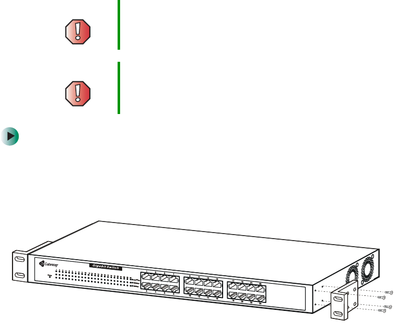
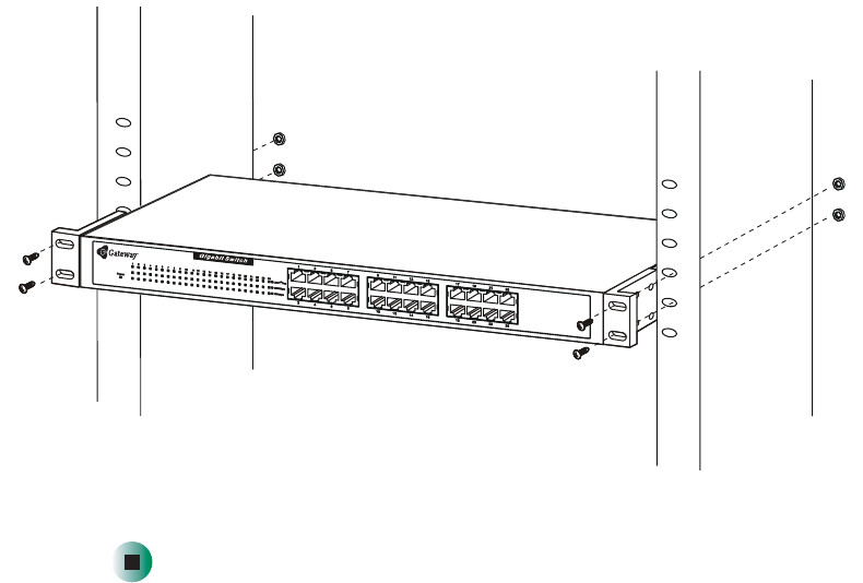
Installing the 16- and 24-port switches in a
rack
The switch can be mounted in a standard 19” rack. Use the following
illustrations to guide you.
To install the switch in a rack:
1Make sure that the switch is turned off and all cables and cords are
unplugged.
2Attach the rack mounting brackets to both sides of the switch with the
machine screws provided.
Warning Before attaching rack mounting hardware, make sure
that the switch is turned off and all power cords are
unplugged.
Warning The rack cabinet must provide sufficient airflow to the
front of the switch to maintain correct cooling. It must
also include ventilation sufficient to exhaust the heat
generated by the equipment installed in the rack.
15
Installing the 16- and 24-port switches
www.gateway.com
3With the assistance of another person, hold the switch in place in the rack
and secure with two screws and nuts on each side (provided.
4Install the cables and power cord.
Power on
Plug one end of the AC power cord into the power connector of the switch
and the other end into the local power source outlet.
After the switch is turned on, the LED indicators will momentarily blink. This
blinking of the LED indicators represents a reset of the system.
Power failure
If a power failure occurs, unplug the switch. When power is resumed, plug the
switch back in.
16
Chapter 2: Installation
www.gateway.com

3
17
Connecting the
Switch
This chapter provides you with information on connecting
Gateway unmanaged switches. Read this chapter to learn
about:
■Connecting to an end node
■Connecting to a hub or switch
■Connecting to a network backbone or server
18
Chapter 3: Connecting the Switch
www.gateway.com
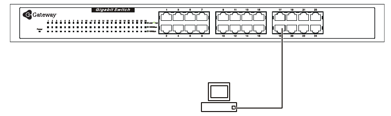
Connecting to an end node
For the Gateway 7201-16 and 7201-24 switches, end nodes include computers
with 10, 100, or 10/100 Mbps RJ-45 Ethernet/Fast Ethernet Network Interface
Cards (NIC). For the Gateway 7401-05, 7401-08, 7401-24, and 7201-24.2
switches, end nodes include computers with 10, 100, or 1000 Mbps RJ-45
Ethernet/Fast Ethernet/Gigabit Network Interface Cards (NIC). End nodes can
also include most routers.
An end node can be connected to the switch through a twisted-pair Category
3, 4, or 5 UTP/STP cable. The end node should be connected to any port on
the switch. End nodes with Gigabit capability should be connected to the
Gigabit capable ports on the Gateway 7201.24.2 switch.
The Link/Act LEDs for each UTP port light green when the port is connected
to a Gigabit Ethernet, Fast Ethernet, or Ethernet station. If the indicator is
blinking green, data is being transmitted or received.
19
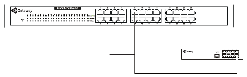
Connecting to a hub or switch
www.gateway.com
Connecting to a hub or switch
These connections can be accomplished in a number of ways using a standard
Ethernet cable.
■A 10BASE-T hub or switch can be connected to the switch through a
twisted-pair Category 3, 4, 5, or 5e UTP/STP cable. Either straight-through
or crossover cables can be used.
■A 100BASE-TX hub or switch can be connected to the switch through a
twisted-pair Category 5 UTP/STP cable. Either straight-through or crossover
cables can be used.
■A 1000BASE-TX switch can be connected to the switch through a
twisted-pair Category 5e or better UTP/STP cable. Either straight-through
or crossover cables can be used.
Straight or Crossover
cable
Switch
or hub
20
Chapter 3: Connecting the Switch
www.gateway.com
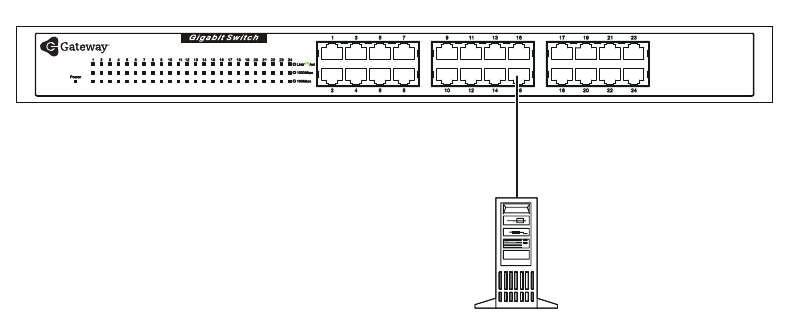
Connecting to a network backbone
or server
On all of the switches, any of the ports are satisfactory for uplinking to a
network backbone or network server. On the Gateway 7201-24.2 switch, use
one of the two Gigabit ports for optimum performance. These ports operate at
1000 Mbps in full-duplex mode.
A valid connection is indicated when the Link LED is lit.

A
21
Specifications
This chapter provides you with the specifications for
Gateways’ unmanaged switches.

22
Appendix A: Specifications
www.gateway.com
Gateway 7401-24 (24-port), gigabit Ethernet
switch
General
Standards: IEEE 802.3ab 1000BASE-T Gigabit Ethernet
IEEE 802.3u 100BASE-TX Fast Ethernet
IEEE 802.3 10BASE-T Ethernet
IEEE 802.3 NWay Auto-negotiation
IEEE 802.3x Flow Control
Protocols: CSMA/CD
Data Transfer
Rates:
Ethernet:
10Mbps (Half-duplex)
20Mbps (Full-duplex)
Fast Ethernet:
100Mbps (Half-duplex)
200Mbps (Full-duplex)
Gigabit Ethernet:
2000Mbps (Full-duplex)
To p o l o gy : S t a r
Network Cables: Ethernet: 2-pair UTP Cat. 3, 4, 5, EIA/TIA-568 100-ohm
screened twisted-pair (UTP)
Fast Ethernet: 2-pair UTP Cat. 5, EIA/TIA-568 100-ohm
screened twisted-pair (UTP)
Gigabit Ethernet: 4-pair UTP Cat. 5, EIA/TIA-568
100-ohm screened twisted-pair (UTP)
Ports 24 10/100/1000BASE-T Gigabit Ethernet ports
Physical & Environmental
AC Inputs: 100 - 240 VAC, 50/60 Hz (internal universal power
supply)
Power
Consumption:
40 Watts maximum
Operating
Temperature:
32 to 104 degrees Fahrenheit (0 to 40 degrees Celsius)

23
www.gateway.com
Storage
Temperature:
14 to 158 Fahrenheit (-10 to 70 degrees Celsius)
Humidity: Operating: 5% to 95% RH, non-condensing
Storage: 0% to 95% RH, non-condensing
Dimensions: 17.36 x 8.15 x 1.73 inches (440 mm x 210 mm x 44 mm)
1U, 19 inch rack-mount width
Weight: 6.6 lbs. (3 Kg)
Performance
Transmission
Method:
Store-and-forward
RAM Buffer: 2M bits per device
Filtering Address
Ta b le :
4K MAC address per device
MAC Address
Learning:
Self-learning, auto-aging
Physical & Environmental

24
Appendix A: Specifications
www.gateway.com
Gateway 7401-05 (5-port), and 7401-08 (8-port)
gigabit Ethernet switches
General
Standards: IEEE 802.3ab 1000BASE-T Gigabit Ethernet
IEEE 802.3u 100BASE-TX Fast Ethernet
IEEE 802.3 10BASE-T Ethernet
IEEE 802.3x Flow Control
Protocols: CSMA/CD
Data Transfer
Rates:
Ethernet:
10Mbps (Half-duplex)
20Mbps (Full-duplex)
Fast Ethernet:
100Mbps (Half-duplex)
200Mbps (Full-duplex)
Gigabit Ethernet:
2000Mbps (Full-duplex)
To p o l o gy : S t a r
Network Cables: Ethernet: 2-pair UTP Cat. 3, 4, 5, EIA/TIA-568 100-ohm
screened twisted-pair (UTP)
Fast Ethernet: 2-pair UTP Cat. 5, EIA/TIA-568 100-ohm
screened twisted-pair (UTP)
Gigabit Ethernet: 4-pair UTP Cat. 5, EIA/TIA-568
100-ohm screened twisted-pair (UTP)
Ports 5 or 8 10/100/1000BASE-T Gigabit Ethernet ports
Physical & Environmental
DC Inputs: 5V/3A
Power
Consumption:
11 Watts maximum,
Operating
Temperature:
32 to 104 degrees Fahrenheit (0 to 40 degrees Celsius)

25
www.gateway.com
Storage
Temperature:
14 to 158 Fahrenheit (-10 to 70 degrees Celsius)
Humidity: Operating: 5% to 95% RH, non-condensing
Storage: 0% to 95% RH, non-condensing
Dimensions: 9.25 × 6.37 × 1.4 inches (235 mm × 161.9 mm × 35.6
mm)
Weight: 6.6 lbs. (3 Kg)
Performance
Transmission
Method:
Store-and-forward
RAM Buffer: 1M Bytes per device
Filtering Address
Ta b le :
4K MAC address per device
Packet
Filtering/Forward
ing Rate:
Full wire speed
MAC Address
Learning:
Self-learning, auto-aging
Physical & Environmental

26
Appendix A: Specifications
www.gateway.com
Gateway 7201-16 (16-port), and 7201-24
(24-port), fast Ethernet switches
General
Standards: IEEE 802.3u 100BASE-TX Fast Ethernet
IEEE 802.3 10BASE-T Ethernet
IEEE 802.3x Flow Control
Protocols: CSMA/CD
Data Transfer
Rates:
Ethernet:
10Mbps (Half-duplex)
20Mbps (Full-duplex)
Fast Ethernet:
100Mbps (Half-duplex)
200Mbps (Full-duplex)
To p o l o gy : S t a r
Network Cables: Ethernet: 2-pair UTP Cat. 3, 4, 5, EIA/TIA-568 100-ohm
screened twisted-pair (UTP)
Fast Ethernet: 2-pair UTP Cat. 5, EIA/TIA-568 100-ohm
screened twisted-pair (UTP)
Ports 16 or 24 10/100/BASE-T Fast Ethernet ports
Physical & Environmental
AC Inputs: 100 - 240 VAC, 50/60 Hz (internal universal power
supply)
Power
Consumption:
40 Watts maximum,
Operating
Temperature:
32 to 104 degrees Fahrenheit (0 to 40 degrees Celsius)
Storage
Temperature:
14 to 158 Fahrenheit (-10 to 70 degrees Celsius)
Humidity: Operating: 5% to 95% RH, non-condensing
Storage: 0% to 95% RH, non-condensing
Dimensions: 5.55 × 8.15 × 1.69 inches (441 mm × 207 mm × 43 mm)

27
www.gateway.com
Weight: 6.6 lbs. (3Kg)
Performance
Transmission
Method:
Store-and-forward
RAM Buffer: 1M Bytes per device
Filtering Address
Ta b le :
4K MAC address per device
Packet
Filtering/Forward
ing Rate:
Full wire speed
MAC Address
Learning:
Self-learning, auto-aging
Physical & Environmental

28
Appendix A: Specifications
www.gateway.com
Gateway 7201-24.2 (24-port), fast Ethernet
switch + 2GTP switch
General
Standards: IEEE 802.3ab 1000BASE-T Gigabit Ethernet
IEEE 802.3u 100BASE-TX Fast Ethernet
IEEE 802.3 10BASE-T Ethernet
IEEE 802.3x Flow Control
Protocols: CSMA/CD
Data Transfer
Rates:
Ethernet:
10Mbps (Half-duplex)
20Mbps (Full-duplex)
Fast Ethernet:
100Mbps (Half-duplex)
200Mbps (Full-duplex)
Gigabit Ethernet:
2000Mbps (Full-duplex)
To p o l o gy : S t a r
Network Cables: Ethernet: 2-pair UTP Cat. 3, 4, 5, EIA/TIA-568 100-ohm
screened twisted-pair (UTP)
Fast Ethernet: 2-pair UTP Cat. 5, EIA/TIA-568 100-ohm
screened twisted-pair (UTP)
Gigabit Ethernet: 4-pair UTP Cat. 5, EIA/TIA-568
100-ohm screened twisted-pair (UTP)
Ports 24 10/100BASE-T Fast Ethernet ports
2 10/100/1000BASE-T Gigabit Ethernet ports
Physical & Environmental
AC Inputs: 100 - 240 VAC, 50/60 Hz (internal universal power
supply)
Power
Consumption:
40 Watts maximum,
Operating
Temperature:
32 to 104 degrees Fahrenheit (0 to 40 degrees Celsius)

29
www.gateway.com
Storage
Temperature:
14 to 158 Fahrenheit (-10 to 70 degrees Celsius)
Humidity: Operating: 5% to 95% RH, non-condensing
Storage: 0% to 95% RH, non-condensing
Dimensions: 5.55 × 8.15 × 1.69 inches (441 mm × 207 mm × 43 mm)
Weight: 6.6 lbs. (3Kg)
Performance
Transmission
Method:
Store-and-forward
RAM Buffer: 1M Bytes per device
Filtering Address
Ta b le :
4K MAC address per device
Packet Filtering/
Forwarding Rate:
Full wire speed
MAC Address
Learning:
Self-learning, auto-aging
Physical & Environmental
30
Appendix A: Specifications
www.gateway.com

B
31
Safety,
Regulatory, and
Legal Information
Important safety
information
Your Gateway switch is designed and tested to meet the latest standards
for safety of information technology equipment. However, to ensure safe
use of this product, it is important that the safety instructions marked on
the product and in the documentation are followed.
Warning Always follow these instructions to help
guard against personal injury and damage
to your Gateway switch.

32
Appendix B: Safety, Regulatory, and Legal Information
www.gateway.com
Setting up your switch
■Read and follow all instructions marked on the product and in the documentation before you
operate your switch. Retain all safety and operating instructions for future use.
■Do not use this product near water or a heat source such as a radiator.
■Set up the switch on a stable work surface.
■The product should be operated only from the type of power source indicated on the rating label.
■If your switch has a voltage selector switch, make sure that the switch is in the correct position
for your area. The voltage selector switch is set at the factory to the correct voltage.
■Openings in the case are provided for ventilation. Do not block or cover these openings. Make
sure you provide adequate space, at least 6 inches (15 cm), around the system for ventilation
when you set up your work area. Never insert objects of any kind into the ventilation openings.
■Some products are equipped with a three-wire power cord to make sure that the product is
correctly grounded when in use. The plug on this cord will fit only into a grounding-type outlet.
This is a safety feature. If you are unable to insert the plug into an outlet, contact an electrician
to install the appropriate outlet.
■If you use an extension cord with this switch, make sure that the total ampere rating on the
products plugged into the extension cord does not exceed the extension cord ampere rating.
General precautions for rack-mountable products
Observe the following precautions for rack stability and safety. Also refer to the rack installation
documentation accompanying the system and the rack for specific caution statements and
procedures.
Systems are considered to be components in a rack. Thus, “component” refers to any system as
well as to various peripherals or supporting hardware.
Before working on the rack, make sure that the stabilizers are secured to the rack, extended to the
floor, and that the full weight of the rack rests on the floor. Install front and side stabilizers on a
single rack or front stabilizers for joined multiple racks before working on the rack.
Always load the rack from the bottom up, and load the heaviest item in the rack first.
Make sure that the rack is level and stable before extending a component from the rack.
Use caution when pressing the component rail release latches and sliding a component into or out
of a rack; the slide rails can pinch your fingers.
After a component is inserted into the rack, carefully extend the rail into a locking position, and
then slide the component into the rack.
Do not overload the AC supply branch circuit that provides power to the rack. The total rack load
should not exceed 80 percent of the branch circuit rating.
Ensure that correct airflow is provided to components in the rack.
Warning High voltages can enter your computer through both the
power cord and the modem connection. Protect your
computer by using a surge protector. If you have a
telephone modem, use a surge protector that has a
modem jack. If you have a cable modem, use a surge
protector that has an antenna/cable jack. During an
electrical storm, unplug both the surge protector and the
modem.

33
Important safety information
www.gateway.com
Do not step on or stand on any component when servicing other components in a rack.
Preventing static electricity discharge
The components inside your computer are extremely sensitive to static electricity, also known as
electrostatic discharge (ESD).
Before opening the computer case, follow these guidelines:
■Turn off your computer.
■Wear a grounding wrist strap (available at most electronics stores) and attach it to a bare metal
part of your computer.
Important A qualified electrician must perform all connections to DC
power and to safety grounds. All electrical wiring must
comply with applicable local or national codes and
practices.
Warning Never defeat the ground conductor or operate the
equipment in the absence of a suitably installed ground
conductor. Contact the appropriate electrical inspection
authority or an electrician if you are uncertain that suitable
grounding is available.
Warning The switch chassis must be positively grounded to the rack
cabinet frame. Do not attempt to connect power to the
switch until grounding cables are connected. Completed
power and safety ground wiring must be inspected by a
qualified electrical inspector. An electrical hazard will exist
if the safety ground cable is omitted or disconnected.
Warning ESD can permanently damage electrostatic
discharge-sensitive components in your computer. Prevent
ESD damage by following ESD guidelines every time you
open the computer case.
Warning To avoid exposure to dangerous electrical voltages and
moving parts, turn off your computer and unplug the power
cord and modem and network cables before opening the
case.
Warning To prevent risk of electric shock, do not insert any object
into the vent holes of the power supply.

34
Appendix B: Safety, Regulatory, and Legal Information
www.gateway.com
■Touch a bare metal surface on the back of the computer.
■Unplug the power cord and the modem and network cables.
Before working with computer components, follow these guidelines:
■Avoid static-causing surfaces such as carpeted floors, plastic, and packing foam.
■Remove components from their antistatic bags only when you are ready to use them. Do not lay
components on the outside of antistatic bags because only the inside of the bags provide
electrostatic protection.
■Always hold expansion cards by their edges or their metal mounting brackets. Avoid touching
the edge connectors and components on the cards. Never slide expansion cards or components
over any surface.
Care during use
■Do not walk on the power cord or allow anything to rest on it.
■Do not spill anything on the switch. The best way to avoid spills is to avoid eating and drinking
near your switch.
■Some products have a replaceable CMOS battery on the system board. There is a danger of
explosion if the CMOS battery is replaced incorrectly. Replace the battery with the same or
equivalent type recommended by the manufacturer. Dispose of batteries according to the
manufacturer’s instructions.
■When a computer is turned off, a small amount of electrical current still flows through it. To
avoid electrical shock, always unplug all power cables and modem cables from the wall outlets
before cleaning the switch.
■Unplug the switch from the wall outlet and refer servicing to qualified personnel if:
■The power cord or plug is damaged.
■Liquid has been spilled into the switch
■The switch does not operate correctly when the operating instructions are followed.
■The switch was dropped or the case is damaged.
■The switch performance changes.
Replacement parts and accessories
Use only replacement parts and accessories recommended by Gateway.
Important Do not use Gateway products in areas classified as
hazardous locations. Such areas include patient care
areas of medical and dental facilities, oxygen-laden
environments, or industrial facilities.
Warning To reduce the risk of fire, use only No. 26 AWG or larger
telecommunications line cord.
35
Regulatory compliance statements
www.gateway.com
Regulatory compliance
statements
United States of America
Federal Communications Commission (FCC)
Unintentional emitter per FCC Part 15
This device has been tested and found to comply with the limits for a Class B digital device,
pursuant to Part 15 of the FCC rules. These limits are designed to provide reasonable protection
against harmful interference in a residential installation. This equipment generates, uses, and can
radiate radio frequency energy and, if not installed and used in accordance with the instructions,
may cause harmful interference to radio or television reception. However, there is no guarantee
that interference will not occur in a particular installation. If this equipment does cause
interference to radio and television reception, which can be determined by turning the equipment
off and on, the user is encouraged to try to correct the interference by one or more of the following
measures:
■Reorient or relocate the receiving antenna
■Increase the separation between the equipment and receiver
■Connect the equipment to an outlet on a different circuit from that to which the receiver is
connected
■Consult the dealer or an experienced radio/TV technician for help.
Compliance Accessories: The accessories associated with this equipment are: shielded video cable
when an external monitor is connected. These accessories are required to be used in order to
ensure compliance with FCC rules.
FCC declaration of conformity
Responsible party:
Gateway Companies, Inc.
610 Gateway Drive, North Sioux City, SD 57049
(605) 232-2000 Fax: (605) 232-2023
Products:
■Gateway 7201-16
■Gateway 7201-24
■Gateway 7201-24.2
■Gateway 7401-05
■Gateway 7401-08
■Gateway 7401-16
■Gateway 7401-24
For unique identification of the product configuration, please submit the 10-digit serial number
found on the product to the responsible party.
36
Appendix B: Safety, Regulatory, and Legal Information
www.gateway.com
This device complies with Part 15 of the FCC Rules. Operation of this product is subject to the
following two conditions: (1) this device may not cause harmful interference, and (2) this device
must accept any interference received, including interference that may cause undesired operation.
Canada
Industry Canada (IC)
Unintentional emitter per ICES-003
This digital apparatus does not exceed the Class B limits for radio noise emissions from digital
apparatus as set out in the radio interference regulations of Industry Canada.
Le présent appareil numérique n’émet pas de bruits radioélectriques dépassant les limites
applicables aux appareils numériques de Classe B prescrites dans le règlement sur le brouillage
radioélectrique édicté par Industrie Canada.
The Ringer Equivalence Number (REN) assigned to each terminal device provides an indication of
the maximum number of terminals allowed to be connected to a telephone interface. The
termination on an interface may consist of any combination of devices subject only to the
requirement that the sum of the Ringer Equivalence Numbers of all the devices does not exceed 5.
California Proposition 65 Warning
Caution Changes or modifications not expressly approved by
Gateway could void the FCC compliance and negate your
authority to operate the product.
Warning To avoid electrical shock or equipment malfunction do not
attempt to make electrical ground connections by yourself.
Contact the appropriate inspection authority or an
electrician, as appropriate.
Warning This product contains chemicals, including lead, known to
the State of California to cause cancer, birth defects or
reproductive harm.

37
Notices
www.gateway.com
Notices
Copyright © 2004 Gateway, Inc.
All Rights Reserved
14303 Gateway Place
Poway, CA 92064 USA
All Rights Reserved
This publication is protected by copyright and all rights are reserved. No part of it may be reproduced or
transmitted by any means or in any form, without prior consent in writing from Gateway.
The information in this manual has been carefully checked and is believed to be accurate. However, changes are
made periodically. These changes are incorporated in newer publication editions. Gateway may improve and/or
change products described in this publication at any time. Due to continuing system improvements, Gateway is
not responsible for inaccurate information which may appear in this manual. For the latest product updates,
consult the Gateway Web site at www.gateway.com. In no event will Gateway be liable for direct, indirect, special,
exemplary, incidental, or consequential damages resulting from any defect or omission in this manual, even if
advised of the possibility of such damages.
In the interest of continued product development, Gateway reserves the right to make improvements in this
manual and the products it describes at any time, without notices or obligation.
Trademark Acknowledgments
Gateway and the Black-and-White Spot Design are trademarks or registered trademarks of Gateway, Inc. in the
U.S. and other countries. SpotShop, Spotshop.com, and Your:)Ware are trademarks of Gateway, Inc. Intel, Intel
Inside logo, and Pentium are registered trademarks and MMX is a trademark of Intel Corporation. Microsoft, MS,
MS-DOS, and Windows are trademarks or registered trademarks of Microsoft Corporation. All other product
names mentioned herein are used for identification purposes only, and may be the trademarks or registered
trademarks of their respective companies.
Macrovision statement
If your computer has a DVD drive and an analog TV Out port, the following paragraph applies:
This product incorporates copyright protection technology that is protected by method claims of certain U.S.
patents and other intellectual property rights owned by Macrovision Corporation and other rights owners. Use of
this copyright protection technology must be authorized by Macrovision Corporation, and is intended for home
and other limited viewing uses only unless otherwise authorized by Macrovision Corporation. Reverse
engineering or disassembly is prohibited.
38
Appendix B: Safety, Regulatory, and Legal Information
www.gateway.com
39
Index
Numerics
16-port switch
installing 13
installing in rack 14
installing without rack 13
power on 15
24-port switch
installing 13
installing in rack 14
installing without rack 13
power on 15
5-port switch
installing 11
power on 11
8-port switch
installing 11
power on 11
A
accessories
safety precautions 34
B
backbone or server connection 20
C
components, front panel 4
connecting
to an end node 18
to backbone or server 20
to hub or switch 19
D
descriptions, switch 2, 3
E
electrostatic discharge (ESD) 33
end node connection 18
F
features, switch 3
front panel components 4
G
gigabit technology 2
H
hub or switch connection 19
I
indicators, LED 6
installing
16-port switch 13
24-port switch 13
5-port switch 11
8-port switch 11
L
LED indicators 6
P
power on
16-port switch 15
24-port switch 15
5-port switch 11
8-port switch 11
S
safety
static electricity 33
setting up
safety precautions 32
static electricity 33
switch
descriptions 2, 3
features 3
switching technology 2

MAN UNMNGD ETH SWITCH GDE R0 1/04
