Gbc F 60 Users Manual F60 CE
Laminator to the manual 56bf2bc1-9d6f-41a6-9c6b-f796dd0c022a
2015-01-05
: Gbc Gbc-F-60-Users-Manual-166002 gbc-f-60-users-manual-166002 gbc pdf
Open the PDF directly: View PDF ![]() .
.
Page Count: 46
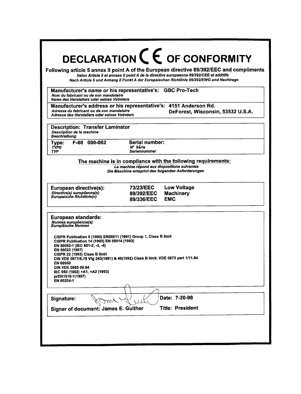

)2SHUDWLRQDQG
0DLQWHQDQFH0DQXDO
© 1998 GBC Pro-Tech
Do not duplicate without written permission
GBC Pro-Tech
4151 Anderson Road
De Forest, Wisconsin 53532
Tel: 608-246-8844
Part Number 930-016
Fax: 608-246-8645
WARNING
ACHTUNG
MISE EN GARDE
WARNING
ACHTUNG
MISE EN GARDE
PRO-TECH
F-60™
CAL 3200
2
100
90
80
70
60
50
40
30
20
10
1
2
3
4567
8
9
10
CAL 3200

F-60 Operation and Maintenance Manual
ii
© GBC Pro-Tech 1998 July
The information in this publication is provided for reference and is believed to be accurate
and complete. GBC Pro-Tech is not liable for errors in this publication or for incidental or
consequential damage in connection with the furnishing or use of the information in this
publication, including, but not limited to, any implied warranty of fitness or merchantabil-
ity for any particular use.
GBC Pro-Tech reserves the right to make changes to this publication and to the products
described in it without notice. All specifications and information concerning products are
subject to change without notice.
Reference in this publication to information or products protected by copyright or patent
does not convey any license under the rights of GBC Pro-Tech or others. GBC Pro-Tech
assumes no liability arising from infringements of patents or any other rights of third par-
ties.
This manual is copyrighted ©1998 by GBC Pro-Tech. All rights reserved. The information
contained in this manual is proprietary and may not be reproduced, stored, transmitted, or
transferred, in whole or in part, in any form without the prior and express written permis-
sion of GBC Pro-Tech.

F-60 Operation and Maintenance Manual
© GBC Pro-Tech 1998 July
iii
Caution/Warnin
g
Label Locations ...................................................................................1-3
Preinstallation Checklist ..................................................................................................2-1
Unpackin
g
.......................................................................................................................2-3
Setup ..............................................................................................................................2-5
Levelin
g
.......................................................................................................................... 2-5
Startup ............................................................................................................................2-6
Safety ..............................................................................................................................3-1
Operator Controls ........................................................................................................... 3-2
Front Control Panel .....................................................................................................3-2
Footswitch Operation ..................................................................................................3-2
Setup .............................................................................................................................. 3-3
Laminator Roll Pressure .............................................................................................3-3
Web Up Options ..........................................................................................................3-3
Loadin
g
the Film .............................................................................................................3-3
Recommended Films ...................................................................................................... 3-3
Positionin
g
the Film ........................................................................................................ 3-4
Heatin
g
........................................................................................................................... 3-4
Pull Roll Clutch Adjustment ............................................................................................ 3-4
Raisin
g
and Lowerin
g
the Pull Rolls ............................................................................... 3-4
Paper Tips ....................................................................................................................... 3-4
Process Control Charts ................................................................................................... 3-5
Mountin
g
Only .................................................................................................................3-6
Setup ...........................................................................................................................3-6
Procedure ...................................................................................................................3-6
Mountin
g
/Laminatin
g
......................................................................................................3-6
Setup ...........................................................................................................................3-6
Procedure ...................................................................................................................3-6
Encapsulation .................................................................................................................3-6
Setup ...........................................................................................................................3-6
Procedure ...................................................................................................................3-6
Two-Pass Mount and Laminate (Hot and Cold) .............................................................. 3-6
F-60 Operation and Maintenance Manual
iv
© GBC Pro-Tech 1998 July
Setup ..........................................................................................................................3-6
Procedure, Pass 1 ...................................................................................................... 3-6
Procedure, Pass 2 ...................................................................................................... 3-7
Cleanin
g
......................................................................................................................... 4-1
Adjustin
g
the Nip ............................................................................................................ 4-3
Chain Tensionin
g
............................................................................................................ 4-4
Lubrication ...................................................................................................................... 4-5
Contactin
g
Technical Support ......................................................................................... 4-5
Output Troubleshootin
g
Guide ........................................................................................ 4-6
Limited Warranty ............................................................................................................. 5-1
Exclusions to the Warranty ......................................................................................... 5-1
F-60 Operation and Maintenance Manual
© GBC Pro-Tech 1998 July
1-1
Your safety, as well as the safety of others, is important
to GBC Pro-Tech. This section contains important
safety information.
The following symbols are used throughout this man-
ual to indicate warnings and cautions.
DANGER
WARNING
CAUTION
The F-60 Laminator has been designed with safety as a
primary consideration. However, you must become
thoroughly familiar with the controls, proper operation,
proper service procedures, and safety features of the
laminator before using or servicing the unit.
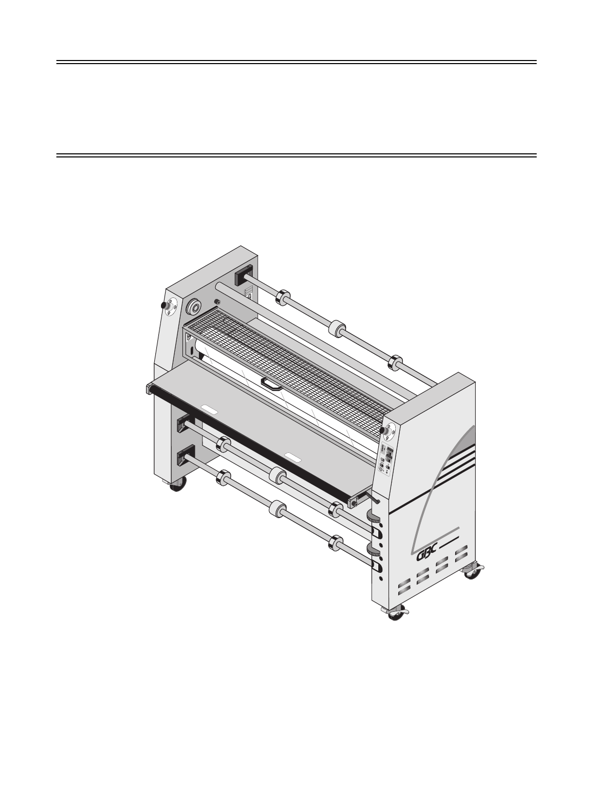
GBC Pro-Tech F-60 Laminator is a powerful machine
that is designed to mount, laminate and encapsulate.
The forces required to accomplish these tasks can vary
from negligible to very large.
In addition, the laminating roll of the F-60 can reach
temperatures of 270 °F (132 °C). At these temperatures
there is a danger of a severe burn if the roll is touched
during set-up, operation or servicing.
Safety is an important feature of the F-60 Laminator. It
has emergency stop buttons and a mechanical guard
system on the infeed. In addition, the pull rolls are con-
tained in an enclosure to prevent injury.
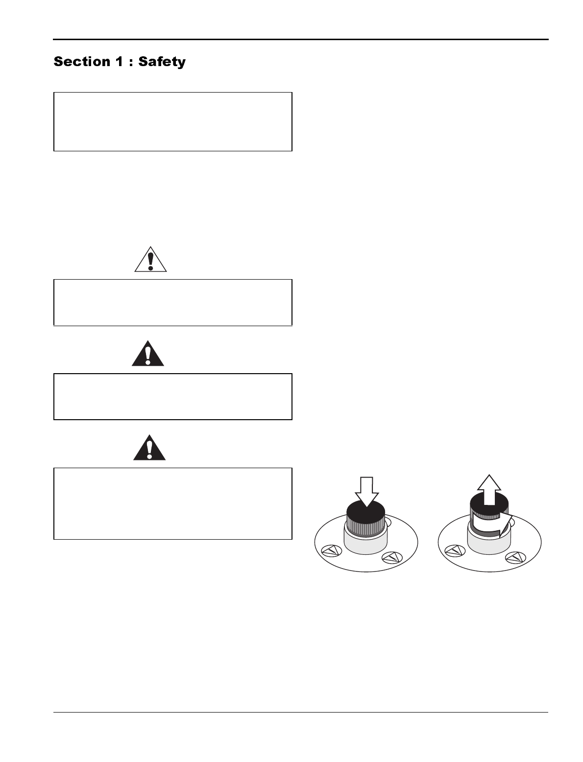
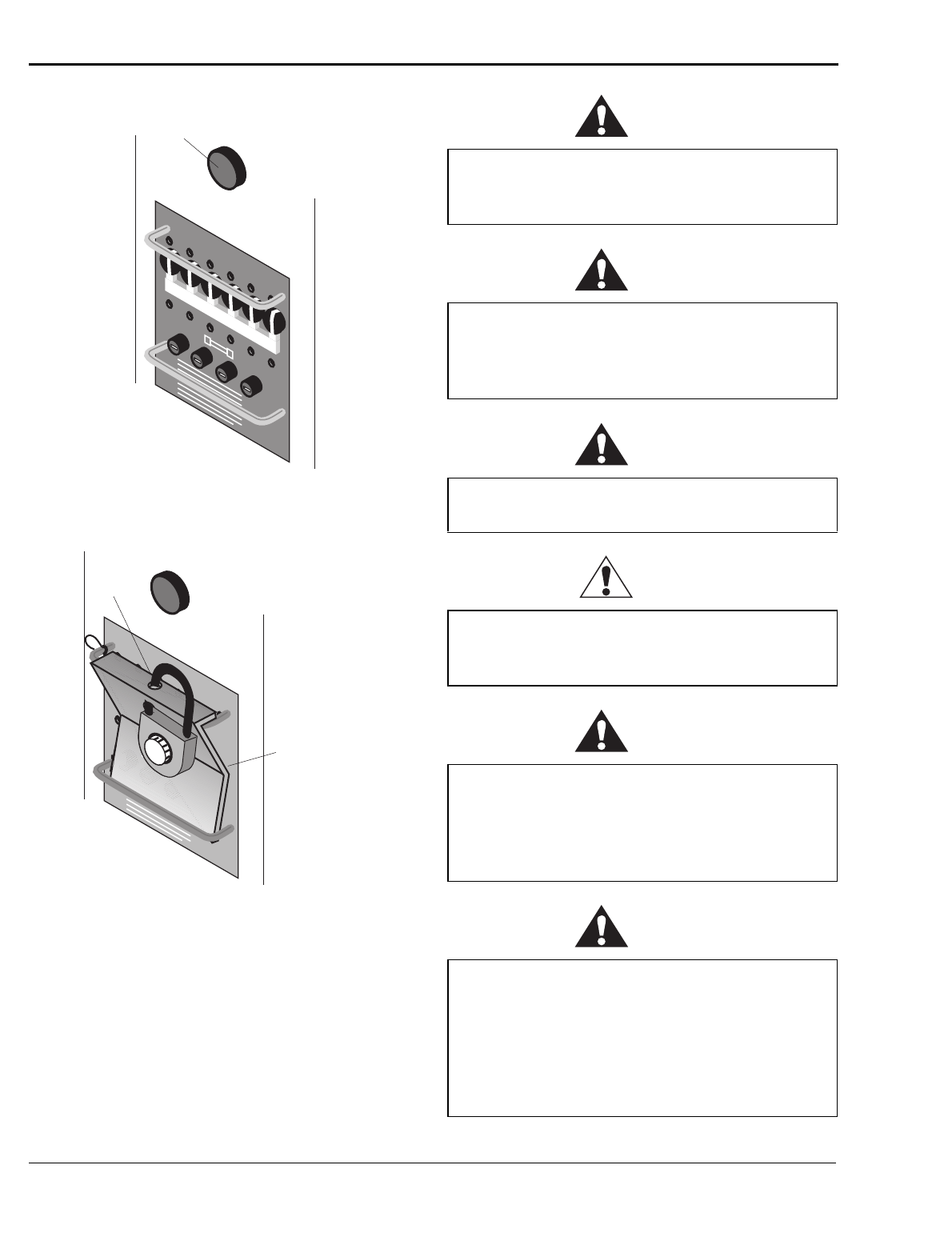
The laminator is equipped with four emergency stop
buttons located on the top front and back of either side
of the laminator. Any of these, if engaged, stops the
laminator. To continue operation all emergency stop
buttons must be in the up position and you must press
the reset button above the fuse panel on the back of the
laminator (see Figure 1-2). The laminator is also
equipped with a power lockout (see Figure 1-3) which
stops power to the machine.
Figure 1-1: Using the Emergency Stop Buttons
DO NOT ATTEMPT TO OPERATE YOUR
ORCA-IV VINYL TRANSFER MACHINE
UNTIL YOU HAVE READ THIS SECTION
CAREFULLY!
Indicates an imminently hazardous situation
which, if not avoided, will result in death or
serious injury.
Indicates a potentially hazardous situation
which, if not avoided, could result in death or
serious injury.
Indicates a potentially hazardous situation
which, if not avoided, could result in minor or
moderate injury, or alerts against unsafe
practices, or alerts against actions which could
damage the product.
1
/
4
tu
r
n
Twist pressed
button to resume
operation - the
button pops up
Push either
button to stop the
laminator
Safety
F-60 Operation and Maintenance Manual
1-2
© GBC Pro-Tech 1998 July
Figure 1-2: Resetting the Laminator
Figure 1-3: Power Lockout
Despite the safety features built into the F-60 Lamina-
tor, extreme caution must be used when operating or
servicing the unit. READ THE FOLLOWING
WARNINGS AND CAUTIONS BEFORE
ATTEMPTING TO OPERATE OR SERVICE THE
F-60 LAMINATOR.
WARNING
WARNING
WARNING
DANGER
WARNING
WARNING
POWER
Reset Button
POWER
Insert
Lock
Circuit
Breakers
Secured in
"Off" Position
Never place fingers or arms between the rolls
when they are turning or when the rolls are in the
closed position. You can be crushed or burned.
Do not wear ties, loose fitting clothing or
dangling jewelry while operating or servicing the
laminator. These items can get caught in the nip
and choke you or you can be crushed or burned.
Do not operate the laminator near water. You can
be severely shocked, electrocuted or cause a fire.
Remove and lock out power from the laminator
before servicing. You can be severely shocked,
electrocuted or cause a fire.
Do not use liquid or aerosol cleaners on the
laminator. Do not spill liquid of any kind on the
laminator. You can be severely shocked,
electrocuted or cause a fire. Use only a damp
cloth for cleaning.
Exercise care when cleaning the rolls with 80%
isopropyl alcohol:
• Use only in a well ventilated area.
• Wear rubber gloves.
• Use only on cool rolls.
Cleaning heated rolls can ignite the fumes.
F-60 Operation and Maintenance Manual
© GBC Pro-Tech 1998 July
1-3
CAUTION
CAUTION
CAUTION
CAUTION
WARNING
CAUTION
WARNING
WARNING
WARNING
Always use good safety practices when operating or
servicing the laminator and know how to react quickly
in an emergency.
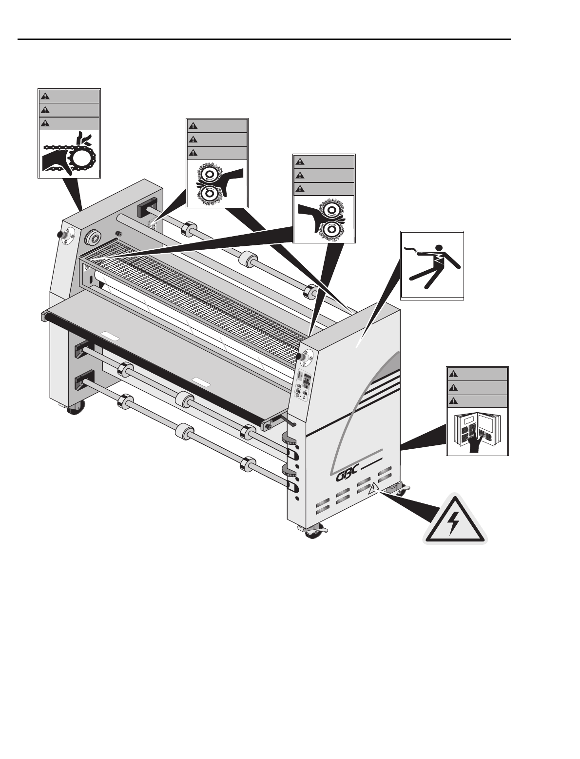
Posted at various locations on your F-60 Laminator are
important safety labels. PAY CAREFUL ATTENTION
TO THESE LABELS AT ALL TIMES! Figure 1-4
shows the location of each of these labels.
Use only 80% isopropyl alcohol or a rubber
cement eraser to clean the laminating rolls.
Harsh chemicals like toluene, acetone or MEK
destroy the silicone covering of the rolls.
Raise the upper main roll when the laminator is
not in operation. Prolonged contact can damage
the rolls.
Excess pressure can damage the laminating rolls.
Always select the minimum roll pressure
necessary to complete the task.
If silicone adhesive contacts the upper or lower
roll, remove it IMMEDIATELY using 80%
isopropyl alcohol. It can harden within an hour
and ruin the roll.
The operating environment must be free of dust,
flammable liquids and vapors. You can be
injured by inhaling chemical vapors. Vapor build
up or stored flammable liquids can cause a fire.
Excessive dust can damage the laminator.
Do not use a knife or other sharp instrument
during installation or while servicing the
laminator. You can cause irreparable damage to
the rolls.
Do not attempt to move the laminator across
anything other than a flat, level surface without
trained and qualified riggers. You can be crushed
or seriously injured.
The F-60 Laminator is a large and heavy piece of
equipment. It is necessary to employ LICENSED
RIGGERS ONLY to move the machine. GBC
Pro-Tech’s warranty does not cover malfunction
of the equipment due to mishandling.
GBC Pro-Tech bears no responsibility for
personal injury or damage due to moving the
laminator improperly.
Do not operate the laminator if the power cord is
damaged or frayed. You can be severely shocked,
electrocuted or cause a fire. Contact a qualified
electrician to replace the cord.
Do not allow anything to rest on the power cord.
Do not locate the cord where people can walk on
it. You or others can be severely shocked,
electrocuted or cause a fire.
Safety
F-60 Operation and Maintenance Manual
1-4
© GBC Pro-Tech 1998 July
Figure 1-4: Locations of Safety Labels
WARNING
ACHTUNG
MISE EN GARDE
WARNING
ACHTUNG
MISE EN GARDE
PRO-TECH
F-60™
(Inside cabinet)
(Inside cabinet)
CAL 3200
2
100
90
80
70
60
50
40
30
20
10
1
2
3
4567
8
9
10
CAL 3200
WARNING
ACHTUNG
MISE EN GARDE
WARNING
ACHTUNG
MISE EN GARDE
WARNING
ACHTUNG
MISE EN GARDE
©1994 Hazard Communication Systems, Inc. 800-748-0241
WARNING
ACHTUNG
MISE EN GARDE
F-60 Operation and Maintenance Manual
© GBC Pro-Tech 1998 July
1-5
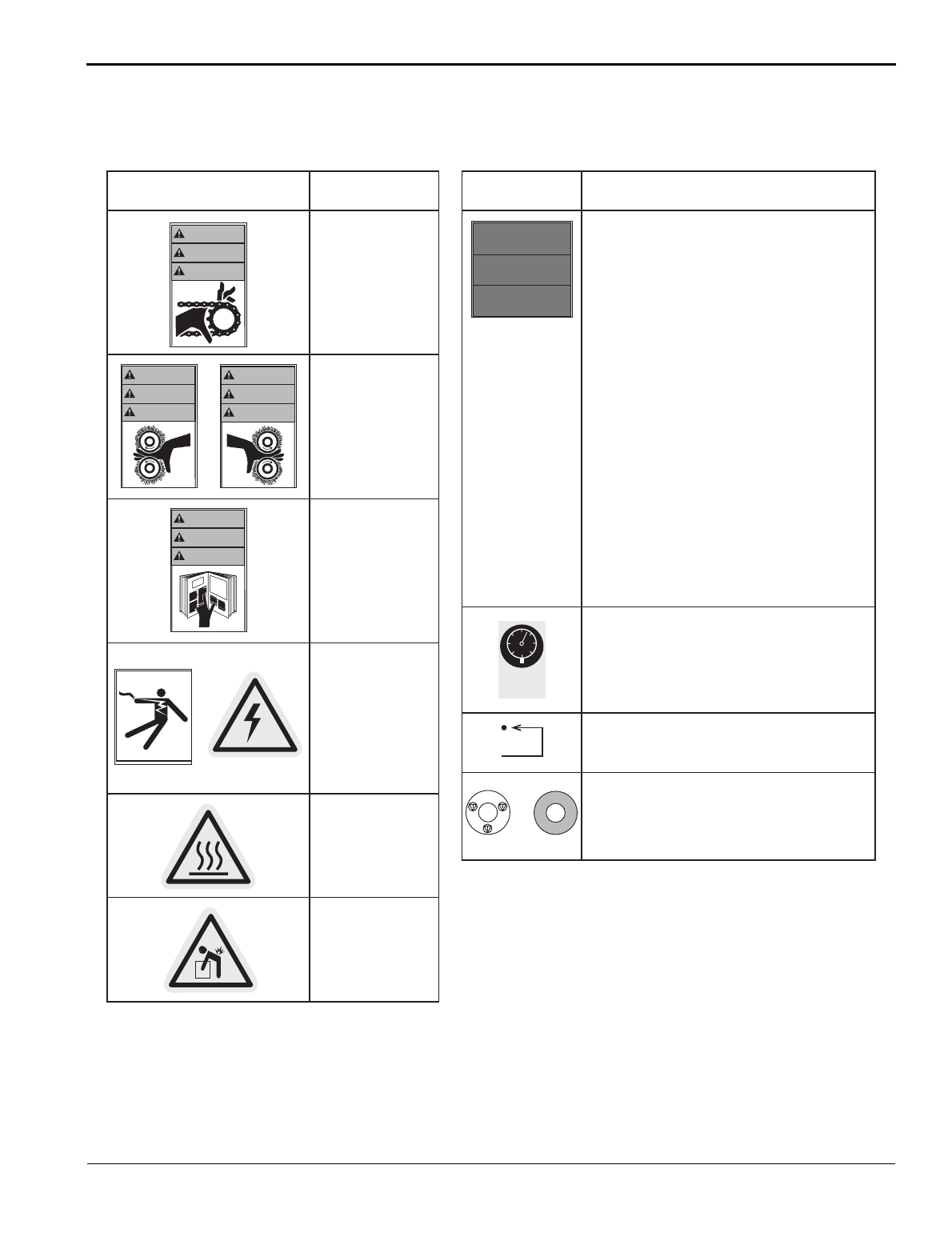
The following are typical safety hazard decals used on GBC Pro-Tech machines, with a brief description (“Mean-
ing” column) of each decal.
WARNING!
Moving parts can
crush and cut.
Do not operate with
guard or door open.
WARNING!
Crush and burn
hazard. Stay clear of
moving rollers. Stop
machine and raise roll
before cleaning.
WARNING!
Carefully read
Operator's Manual
before handling this
machine. Observe
instructions and safety
rules when operating.
WARNING!
HAZARDOUS
VOLTAGE.
To be serviced only by
trained and authorized
personnel.
Lockout power before
servicing.
Reset.
CAUTION!
Surface is hot.
A burn hazard exists.
WARNING!
1. Read and understand the Operation Manual and
all safety labels before operating this machine.
2. Only a trained person is to be permitted to operate
this machine. Training should include instruction
in operation under normal conditions and
emergency situations.
3. This machine is to be serviced only by trained and
authorized personnel. Follow lockout procedures
before servicing.
4. Never reach into the machine for any reason unless
the machine is at a COMPLETE STOP.
5. Never leave the machine stopped in such a manner
that another worker can start the machine while
you are working on or within the machine.
6. Never change or defeat the function of electrical
interlocks or other machine "shutdown" switches.
7. Before starting this machine, check that:
- All persons are clear of the machine.
- No maintenance work is being performed on
the machine.
- All guards are in place.
- All parent rolls are well chucked in the unwind
stands.
- The machine is free of paper scraps, wraps and
jams.
8. There is a potential hazard of entanglement in this
machine caused by items such as long hair, loose
clothing, and jewelry. Make sure your clothing and
hair fit closely to your body and that all jewelry,
rings and watches are removed.
Decal Meaning Decal Meaning
or
WARNING
ACHTUNG
MISE EN GARDE
WARNING
ACHTUNG
MISE EN GARDE
or
≤ 100 PSI
≥ 700 KPa
©1997 HCS, Inc. 800-748-0241 No. 6101-52BVPK
CAUTION!
Rolls are heavy.
Use proper lifting
techniques to prevent
injury.
CAUTION!
Air pressure must be less than 100 PSI (700 kPa) to
avoid damaging the machine.
or
N
O
T
A
U
S
E
M
E
R
G
E
N
C
Y
S
T
O
P
A
R
R
E
T
D
'
U
R
G
E
N
C
E
WARNING!
EMERGENCY STOP BUTTON
Press this button to stop the machine cycle, remove
electric power, and separate (open) rolls to eliminate a
pinch point (on some machines).
WARNING
ACHTUNG
MISE EN GARDE
WARNING
ACHTUNG
MISE EN GARDE
SAFETY
INSTRUCTIONS
SICHERHEITS-
RICHTLINIEN
CONSIGNES DE
SÉCURITÉ
©1994 Hazard Communication Systems, Inc. 800-748-0241

Safety
F-60 Operation and Maintenance Manual
1-6
© GBC Pro-Tech 1998 July
Blank page.
F-60 Operation and Maintenance Manual
Installation
© GBC Pro-Tech 1998 July
2-1
GBC Pro-Tech is committed to a program of ongoing
product improvement. As a result, we are providing
these instructions so that you can insure that your new
F-60 Laminator is properly and securely unpacked,
moved and installed.
Before a F-60 Laminator can be installed, there are a
few requirements that must be met. Make certain that
each of the requirements listed in the following prein-
stallation checklist are met before beginning installa-
tion.
CAUTION
❏Are doorways and hallways wide enough for the
laminator to be moved to the installation site?
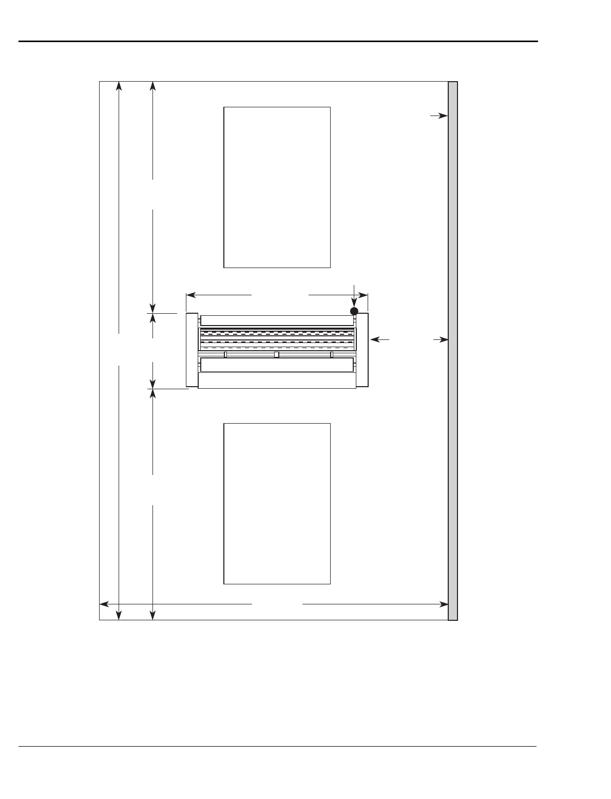
❏Is there ample room for the laminator?
A work area must be established that allows for
operation in both the front and the rear of the
machine and provides space for efficient material
flow. Figure 2-1 shows a typical machine area lay-
out.
❏Is the environment appropriate for the laminator?
The laminator requires a clean, dust and vapor free
environment to operate properly, such as an air
conditioned office area with forced 10% make up
air. However, the laminator must not be located
where there is air blowing directly on it. Major
fluctuation in temperature and humidity are to be
avoided.
WARNING
CAUTION
❏Is there an appropriate power outlet available or
has a certified electrician been contacted to wire
the laminator directly?
The laminator requires 55A single phase, 220/230/
240 VAC service or, in Europe,
3 Phase, 240/400 VAC with 25 Amps per phase.
WARNING
WARNING
WARNING
WARNING
Failure to follow the preinstallation checklist can
result in damage to the laminator.
The operating environment must be free of dust,
flammable liquids and vapors. You can be
injured by inhaling chemical vapors. Vapor build
up or stored flammable liquids can cause a fire.
Excessive dust can damage the laminator.
Do not locate the laminator where air is blowing
directly on the machine. The air flow can cool the
rolls unevenly and result in poor quality output.
Do not attempt to defeat the grounding feature of
the ground plug on the laminator. You can be
severely shocked, electrocuted or cause a fire.
The three prong plug fits only into a grounding-
type power outlet. If you are unable to insert the
plug into the existing outlet, contact a qualified
electrician to replace the obsolete outlet.
Do not use an extension cord on this laminator.
You can be severely shocked, electrocuted or
cause a fire. If you need a longer cable contact a
qualified electrician.
Do not operate the laminator if the power cord is
damaged or frayed. You can be severely shocked,
electrocuted or cause a fire. Contact a qualified
electrician to replace the cord.
Do not allow anything to rest on the power cord.
Do not locate the cord where people can walk on
it. You or others can be severely shocked,
electrocuted or cause a fire.
Installation
F-60 Operation and Maintenance Manual
2-2
© GBC Pro-Tech 1998 July
Figure 2-1: Laminator Space Requirements
78" (~2 m)
3' (~1 m)
Wall
4' x 6' (~1.22 m x 2 m)
Work Table
on Wheels
Table Height
35-3/4"
(~.94 - .95 m)
30"
(~.76 m)
8'6-1/2"
(~2.6 m)
8'6-1/2"
(~2.6 m)
Rear
Front
20'
(~.6 m)
4' x 6' (~1.22 m x 2 m)
Work Table
on Wheels
Table Height
35-3/4"
(~.94 - .95 m)
Electrical
Supply
13' (~4 m)
F-60 Operation and Maintenance Manual
Installation
© GBC Pro-Tech 1998 July
2-3
☞
NOTE
ALL SHIPMENTS ARE EX- WORKS. At our dock title
passes to the buyer. Please review your insurance cov-
erage prior to shipment, as you are responsible for all
subsequent freight charges and risks. Before signing
the Bill of Lading you should be sure to inspect the
crate and/or pallet for signs of damage or missing
items; if applicable, make a note of this on the Bill of
Lading.
The F-60 Laminator is shipped in a wood crate on a
skid.
WARNING
Tools required:
• Phillips head screwdriver
• Adjustable wrench
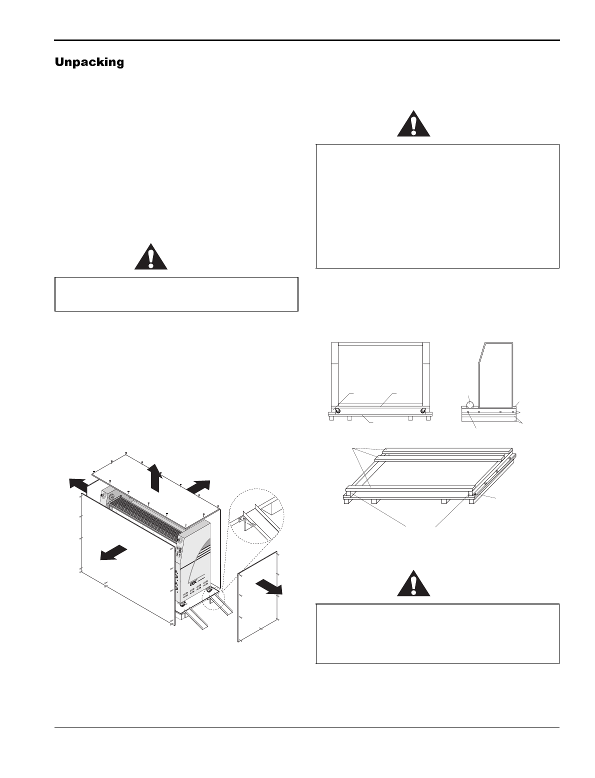
To uncrate the laminator:
1. Remove the top of the crate and sides 2 and 3 as
shown in Figure 2-2.
Figure 2-2: Removing the Crate
2. There are two hold down bridges that are con-
nected to sides 4 and 5. Remove the hold down
bridges and then remove sides 4 and 5.
CAUTION
3. The infeed pressure plate and ramps are attached to
the skid. Remove them and set them aside for later
installation.
Figure 2-3: Skid Configuration
CAUTION
The unpacking process requires at least two
people. You can be severely injured or crushed.
5
3
2
Install
Screws
©1994 HCS, Inc. 800-748-0241Reorder No.1033R-PT
Crush and burn
hazard. Stay clear
of moving rollers.
Stop machine and
raise roll before
cleaning.
WARNING
ACHTUNG
MISE EN GARDE
WARNING
ACHTUNG
MISE EN GARDE
CAL 3200
2
100
90
80
70
60
50
40
30
20
10
1
2
3
4567
8
9
10
CAL 3200
PRO-TECH
NOT
AUS
E
M
E
R
G
E
N
CY
ST
OP
ARR
E
T
D'
U
R
G
E
N
C
E
NOT
AUS
E
M
E
R
G
E
N
CY
ST
OP
ARR
E
T
D'
U
R
G
E
N
C
E
F-60™
CAL 3200
2
100
90
80
70
60
50
40
30
20
10
1
2
3
4567
8
9
10
CAL 3200
4
1
Do not allow the top to fall into the crate. It can
damage the laminator.
Do not put packing screws on the floor. They can
cause problems when trying to roll the machine
into position.
A second person must support the side
labeled (5) in Figure 2-2. It can fall and damage
the laminator.
Do not use a knife or other sharp instrument
during installation or while servicing the
laminator. You can cause irreparable damage to
the rolls.
2" x 4"
Saddle
Skid
Lag Bolt
Heaters
2" x 4"
2" x 4"
Saddle
Saddle
Skid
Lag Bolt
Skid
Installation
F-60 Operation and Maintenance Manual
2-4
© GBC Pro-Tech 1998 July
4. Carefully remove the accessory pack from the skid.
The accessory pack should contain:
1 Set, hex wrenches
1 Slitting knife
1 Manual
1 Set, spare fuses
1 Roll of masking tape
1 100% cotton terry cloth
4 Leveling pads
5. Place the foot switch on the pull roll cover to pre-
vent the foot switch wire from damage during
removal of the machine from the skid.
WARNING
6. The machine is supported above the skid by resting
on a support saddle under each end of the machine.
Remove the three long two by fours that attach to
the support saddles.
7. On one side of the machine, remove the lag bolts
holding the support saddle to the skid.
8. Using two of the two by fours as levers, carefully
lift the end of the machine enough to allow the sad-
dle to be removed from the skid and the machine to
rest on its wheels.
9. Repeat Steps 7 and 8 for the other end of the
machine.
10. The ramps included with the laminator can be
secured to the edge of the crate bottom using the
screws left over from the crate disassembly (see
Figure 2-2).
11. Have the machine moved off the skid and placed
on the floor by licensed riggers.
Roll the machine off by securing included ramps to
the edge of the crate bottom using the screws left
over from the crate disassembly (See Figure 2-2).
Lift the machine off by applying fork lift truck
blades to the two bottom tie bars between the cabi-
nets. The fork lift blades must be located at the lift
label locations on the tie bars (see Figure 2-4).
Figure 2-4:
12. Remove any plastic strapping and packing paper
taped to the rolls.
CAUTION
13. Remove all packing materials to a safe distance
from the laminator.
Do not attempt to move the laminator across
anything other than a flat, level surface without
trained and qualified riggers. You can be crushed
or seriously injured. Steps 6 through 11 should be
completed by LICENSED RIGGERS ONLY.
The F-60 Laminator is a large and heavy piece of
equipment. It is necessary to employ LICENSED
RIGGERS ONLY to move the machine.
GBC Pro-Tech bears no responsibility for
personal injury or damage due to moving the
laminator improperly.
Do not use a knife or other sharp instrument
during installation or while servicing the
laminator. You can cause irreparable damage to
the rolls.
WARNING
ACHTUNG
MISE EN GARDE
WARNING
ACHTUNG
MISE EN GARDE
PRO-TECH
F-60™
CAL 3200
2
100
90
80
70
60
50
40
30
20
10
1
2
3
4567
8
9
10
CAL 3200
Fork Lift Label
Locations

F-60 Operation and Maintenance Manual
Installation
© GBC Pro-Tech 1998 July
2-5
☞
A NOTE ABOUT RECYCLING
The crate components can be reused for shipping the
machine again, or can be disassembled and the wood
and screws recycled. The shrink wrap is not recyclable,
however, so it must be discarded.
14. Level the laminator using the procedure later in
this section.
Once the F-60 Laminator has been unpacked and
moved into final position check each of the following
items.
Tools required:
•1/8" hex wrench
• Adjustable wrench
Setup Procedure:
1. Inspect the laminator for any obvious shipping
damage.
2. Using a 1/8" hex wrench, remove the screws secur-
ing the cabinet panel to the control (electrical) side
of the machine.
3. Using a 1/8" hex wrench, remove the screws secur-
ing the cabinet panel to the drive side of the
machine and rotate the panel around the clutch
knob.
4. Inspect all the bolts and tighten any that were loos-
ened during shipping.
5. Set the nip. (See Maintenance for the procedure.)
6. Replace both cabinet covers.
Tools required:
• Adjustable wrench
• Carpenter's level
To level the laminator:
1. Raise each end, remove the castors and install a
leveling pad and stud onto each of the foot brackets
at the four bottom corners of the laminator. Thread
third nut on stud above foot bracket.
2. Thread stud into 4 leveling pads lock down with
nut. Thread second nut onto stud.
3. Place a carpenter's level front to rear across the two
lower tie bars at one end of the machine.
4. Level this end of the machine front to rear, raising
or lowering the leveling pads by adjusting the mid-
dle nuts on the foot bolts.
5. Move the level to the other end of the machine and
level front to rear.
6. Place the level directly on one of the tie bars and
level the machine side to side.
7. Recheck the front to rear level condition to insure
that it has not changed. If it has, repeat the leveling
procedure.
8. When all the measurements indicate that the
machine is level, tighten down the top nuts on the
foot brackets to lock the pads in their current posi-
tion.
Installation
F-60 Operation and Maintenance Manual
2-6
© GBC Pro-Tech 1998 July
The first time the laminator is started and every time it
is serviced you should use the following checklist to
confirm that the unit is operating properly and that all
safety mechanisms are functioning.
Startup Checklist
Start the laminator and go through the following check-
list.
❏Are the emergency stop buttons working?
Push down on one of the emergency stop buttons.
The laminator should stop. Pull up on the button
and push the reset button on the lower back of the
laminator. The laminator should resume operation.
Always check all buttons.
WARNING
❏Is the mechanical guard system working?
With the laminator running, remove the mechani-
cal guard from the infeed side of the machine. The
rolls should stop. Replace the guard. The laminator
should resume operation.
WARNING
❏Is the footswitch working?
With the laminator running, remove the mechani-
cal guard from the infeed side of the machine. The
rolls should stop. Press the footswitch. The lamina-
tor should resume operation. Vary the speed using
the footswitch (like an automobile accelerator) to
ensure that the footswitch is operating properly at
various speeds.
WARNING
❏Is the motor functioning?
Test the motor at various speeds ranging from
0-15. At 0 the rolls should stop turning.
Run the motor in both forward and reverse.
❏Are the heaters working?
Verify that the heater controller heats the top roll.
Once you have completed the startup checklist you can
safely run a test sample.
Never operate the laminator unless all of the
emergency stop buttons are functioning properly.
You can be crushed or burned.
Never operate the laminator unless the
mechanical guard system is operating properly.
You can be crushed or burned.
Use extreme caution when operating the machine
with the guard off. You can be crushed or
burned.
F-60 Operation and Maintenance Manual
Operation
© GBC Pro-Tech 1998 July
3-1
The F-60 Laminator has been designed with safety as a
primary consideration. However, you must become
thoroughly familiar with the controls, proper operation,
proper service procedures, and safety features of the
laminator before using or servicing the unit.
GBC Pro-Tech F-60 Laminator is a powerful machine
that is designed to mount, laminate and encapsulate.
The forces required to accomplish these tasks can vary
from negligible to very large.
In addition, the laminating roll of the F-60 can reach
temperatures of 270 °F (132 °C). At these temperatures
there is a danger of a severe burn if the roll is touched
during set-up, operation or servicing.
Safety is an important feature of the F-60 Laminator. It
has emergency stop buttons and a mechanical guard
system on the infeed. In addition, the pull rolls are con-
tained in an enclosure to prevent injury.
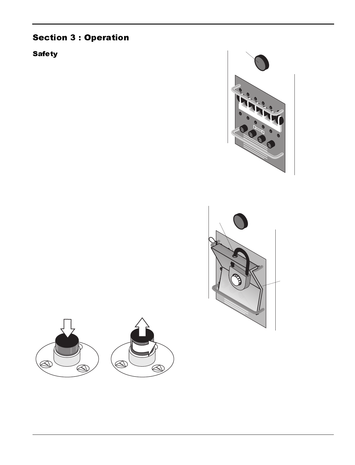
The laminator is equipped with four emergency stop
buttons located on the top front and back of either side
of the laminator. Any of these, if engaged, stops the
laminator. To continue operation all emergency stop
buttons must be in the up position and you must press
the reset button above the fuse panel on the back of the
laminator (see Figure 3-2). The laminator is also
equipped with a power lockout (see Figure 3-3) which
stops power to the machine.
Figure 3-1: Using the Emergency Stop Buttons
Figure 3-2: Resetting the Laminator
Figure 3-3: Power Lockout
1
/
4
tu
r
n
Twist pressed
button to resume
operation - the
button pops up
Push either
button to stop the
laminator
POWER
Reset Button
POWER
Insert
Lock
Circuit
Breakers
Secured in
"Off" Position
Operation
F-60 Operation and Maintenance Manual
3-2
© GBC Pro-Tech 1998 July
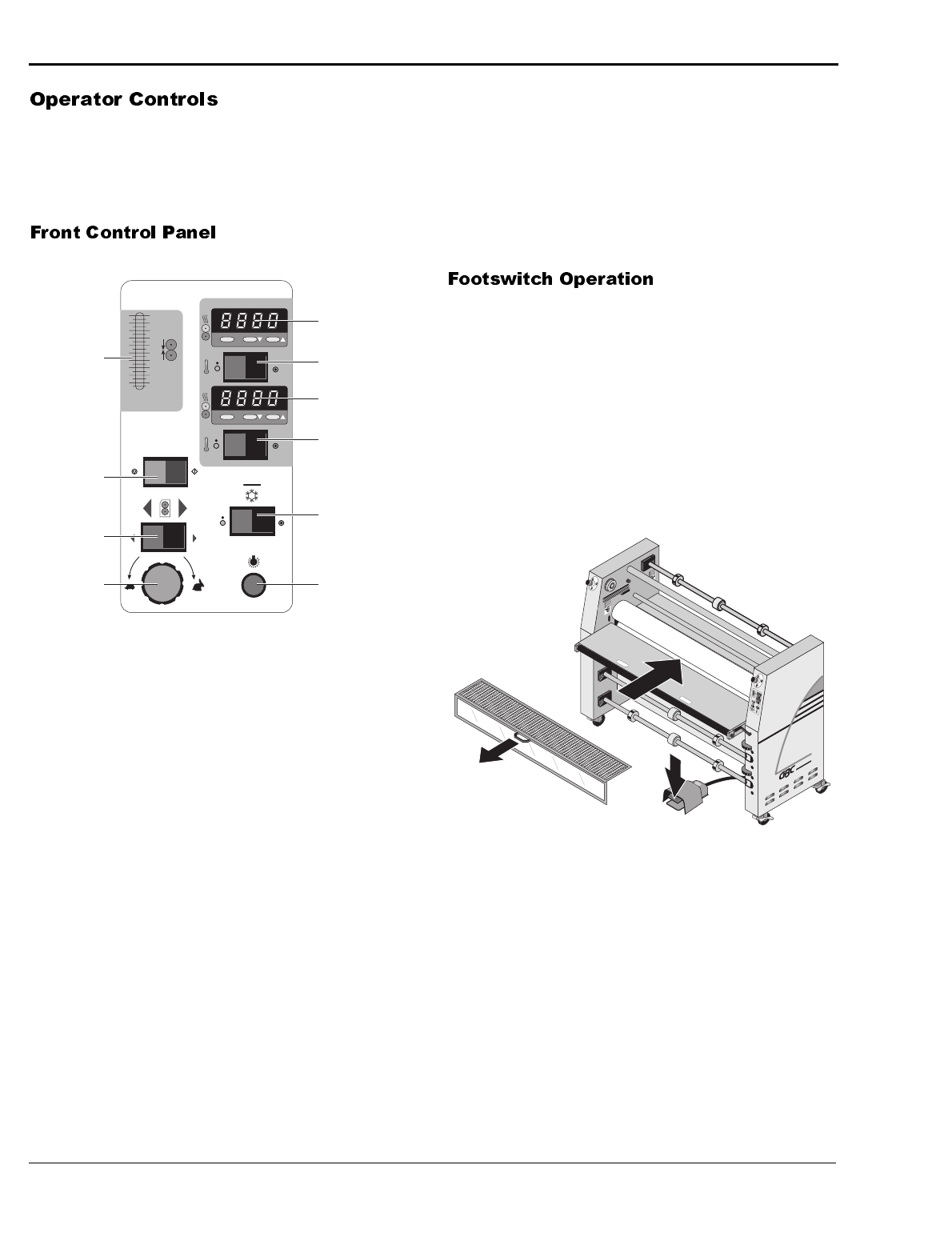
The operator controls for the F-60 Laminator are
located on the front and rear of the unit, to the right of
the operator position. The names and functions of these
controls are as follows:
Figure 3-4: Front Control Panel
1. ROLL PRESSURE DISPLAY - Displays the per-
centage of pressure pushing the main laminating
roll down.
2. RUN/STOP – Turns the drive system on or off.
3. MOTION CONTROL FORWARD/REVERSE -
Controls the direction of the drive system, forward,
reverse, or stop.
4. SPEED ADJUSTMENT – Adjusts the speed of
the machine from zero to the maximum as the con-
trol is turned clockwise. (Turtle is slow, rabbit is
fast.)
5. UPPER ROLL HEATER CONTROLLER –
Provides a readout of the temperature of the upper
roll and the set-point for the desired temperature.
6. UPPER ROLL HEAT ON/OFF – Turns the
heater controller for the upper main roll on or off.
7. LOWER ROLL HEATER CONTROLLER–
Provides a readout of the temperature of the lower
roll and the set-point for the desired temperature.
8. LOWER ROLL HEAT ON/OFF – Turns the
heater controller for the lower main roll on or off.
9. COOLING FAN ON/OFF – Turns the cooling fan
on or off.
10. POWER ON/OFF INDICATOR – Indicates
when the main power is being applied to the
machine.
The footswitch on the F-60 Laminator operates much
like the accelerator on an automobile. When the
mechanical guard is removed, use the footswitch to
feed material into the laminator at the rate you select by
pressing the footswitch. The more pressure you apply,
the faster the rolls turn. When you remove pressure
from the footswitch, the rolls stop.
Figure 3-5: Using the Footswitch
Power On/Off
Indicator
Motion Control
FORWARD/
REVERSE
Speed
Adjustment
1
3
4
5
6
7
10
CAL 3200
2
100
90
80
70
60
50
40
30
20
10
Upper Roll Heat
ON/OFF
Cooling Fan ON/OFF
Upper Roll Heater
Controller
1
2
3
4567
8
9
10
CAL 3200
Lower Roll Heater
Controller
Roll
Pressure
Display
8Lower Roll Heat
ON/OFF
9
RUN/STOP 2
WARNING
ACHTUNG
MISE EN GARDE
PRO-TECH
F-60™
CAL 3200
2
100
90
80
70
60
50
40
30
20
10
1
2
3
4567
8
9
10
CAL 3200
Remove
Guard
Press
Footswitch
(variable
speed)
Feed
Material
Into Nip
WARNING
ACHTUNG
MISE EN GARDE
F-60 Operation and Maintenance Manual
Operation
© GBC Pro-Tech 1998 July
3-3
Setup of the F-60 Laminator is quick and straightfor-
ward when instructions are followed exactly.
To adjust the nip, please see Maintenance.
Use only the minimum amount of roll pressure needed
to accomplish the task. While higher pressure can make
the adhesive bond faster, excess pressure can damage
the rolls. Wrinkles and bubbles have causes that gener-
ally cannot be cured by applying more pressure.
CAUTION
A typical roll pressure for soft substrates such as Foam-
core is between 20 to 30 pounds per square inch (PSI)
or 140 to 205 kPa.
The range of typical values for hard substrates is 25 to
50 PSI or 170 to 345 kPa.
With the guard removed, move webs through the main
roll nip by:
1. Pressing the RUN button for a slow, constant main
roll rotation.
or
2. Pressing the STOP button, then pressing the foot-
switch to set the required speed. Releasing the
footswitch stops main roll rotation.
Film is loaded on the appropriate unwinds. Loading
and aligning the film are discussed later in this section.
For applications such as encapsulation, film is fed from
both the top and bottom feed unwinds.
The process of loading and aligning film is the same
for both the top and the bottom unwinds. There are two
important points to remember when loading film:
1. The adhesive side of the film must be oriented
away (on the outside) from the laminating roll.
Otherwise it will immediately bond to the roll, cre-
ating a major clean-up project.
Films have a shiny side and a dull side. The dull
side is the one with the adhesive. The dull side
should ALWAYS face outward from the laminat-
ing roll.
CAUTION
2. The film must be centered on the unwind for best
performance. This is vital when two films are fed
together. If the two films are not aligned, feed
problems, wrinkles and other assorted troubles will
occur.
CAUTION
The F-60 laminator is capable of processing a wide
range of pressure sensitive and thermal laminates onto
an equally wide range of image materials. The primary
considerations are:
• Laminate adhesives are compatible with image
materials.
• The materials properly activate below the 270°
maximum roll temperature and within the speed and roll
nip pressure ranges available on the laminator.
It is the operator’s responsibility to ensure the compati-
bility and operational settings for any laminates/image
material combination. GBC Pro-Tech Technical Sup-
port is available at the number provided in the Mainte-
nance chapter for advice on some material
combinations.
Excess pressure can damage the laminating rolls.
Minimum laminator roll pressure is consistent
with good results.
Always mount the film so that the adhesive side
faces outward from the laminating roll. This
prevents hours of roll cleaning.
Carefully align the two films being fed into the
nip. If not, you will obtain poor results.
Operation
F-60 Operation and Maintenance Manual
3-4
© GBC Pro-Tech 1998 July
The following procedure is applicable to both the top
and bottom feed unwinds.
1. Open the top unwind by removing the pin and
swinging the arm out.
2. Load the film.
3. Return the arm to its locked position and reinsert
the locking pin.
4. Center the film on the unwind arm by measuring
the distance from the ends of the film to the sides
of the machine using a tape measure.
Use the following instructions when heating one or
both of the laminating rolls. The procedure is the same
for the top and bottom heaters.
1. Set the heater switch to ON.
2. Adjust the temperature controller for the desired
operating temperature using the temperature con-
troller push buttons.
3. When heating the rolls, keep the top roll down and
turning at a moderate speed to prevent uneven
heating.
4. It will take approximately 30 minutes for the lami-
nating roll(s) to reach operating temperature. When
the preset operating temperature has been reached,
the machine is ready to use.
The F-60 Laminator has an adjustable clutch for the
pull rolls on the machine, allowing you to adjust the
amount that the film is tensioned as it leaves the main
rolls and is cooled. The clutch adjustment is made by
using the knob on the left side of the machine.
Pull roll clutch tension adjustment:
Turning the knob clockwise increases tension.
Turning the knob counterclockwise decreases tension.
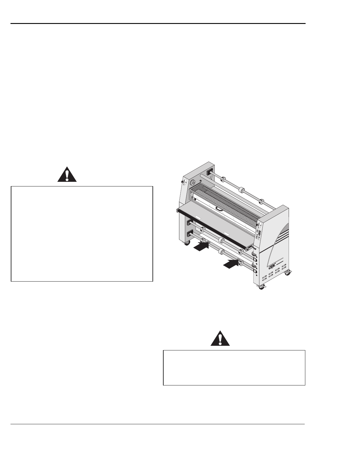
The pull rolls on the F-60 Laminator are preset for opti-
mum roll pressure and requires no nip adjustment. The
pull rolls can be raised for a 3/8" gap that allows for
easy webbing of the machine.
Prior to raising or lowering the pull rolls, the pull roll
cover must be raised and locked into place.
The pull roll lever is located next to the pull rolls. To
lower the pull rolls, lift the lever up and rotate the lever
until it rests on the center table. To raise the pull rolls,
rotate the lever back down until it locks into place.
To proceed with operation of the machine, the pull roll
cover must be lowered.
CAUTION
Always feed prints perpendicular to the laminating
rolls.
1. Lock core support to middle of the shaft. Lock two
core chucks on shaft ends, located to support mate-
rial a few inches from ends of the roll.
☞
Note
Paper unwind may require two evenly spaced core sup-
ports if wide rolls of prints (paper) are used.
2. Place the roll on the unwind shaft.
3. Carefully close the unwind shaft, holding the roll
away from the hinge.
4. When the shaft is in the saddle, push in the locking
pin.
5. Center the roll of material.
6. Web and tension film per process control chart and
diagram.
When the machine is not in use, the pull rolls
must be raised to prevent damaging the rolls.
F-60 Operation and Maintenance Manual
Operation
© GBC Pro-Tech 1998 July
3-5
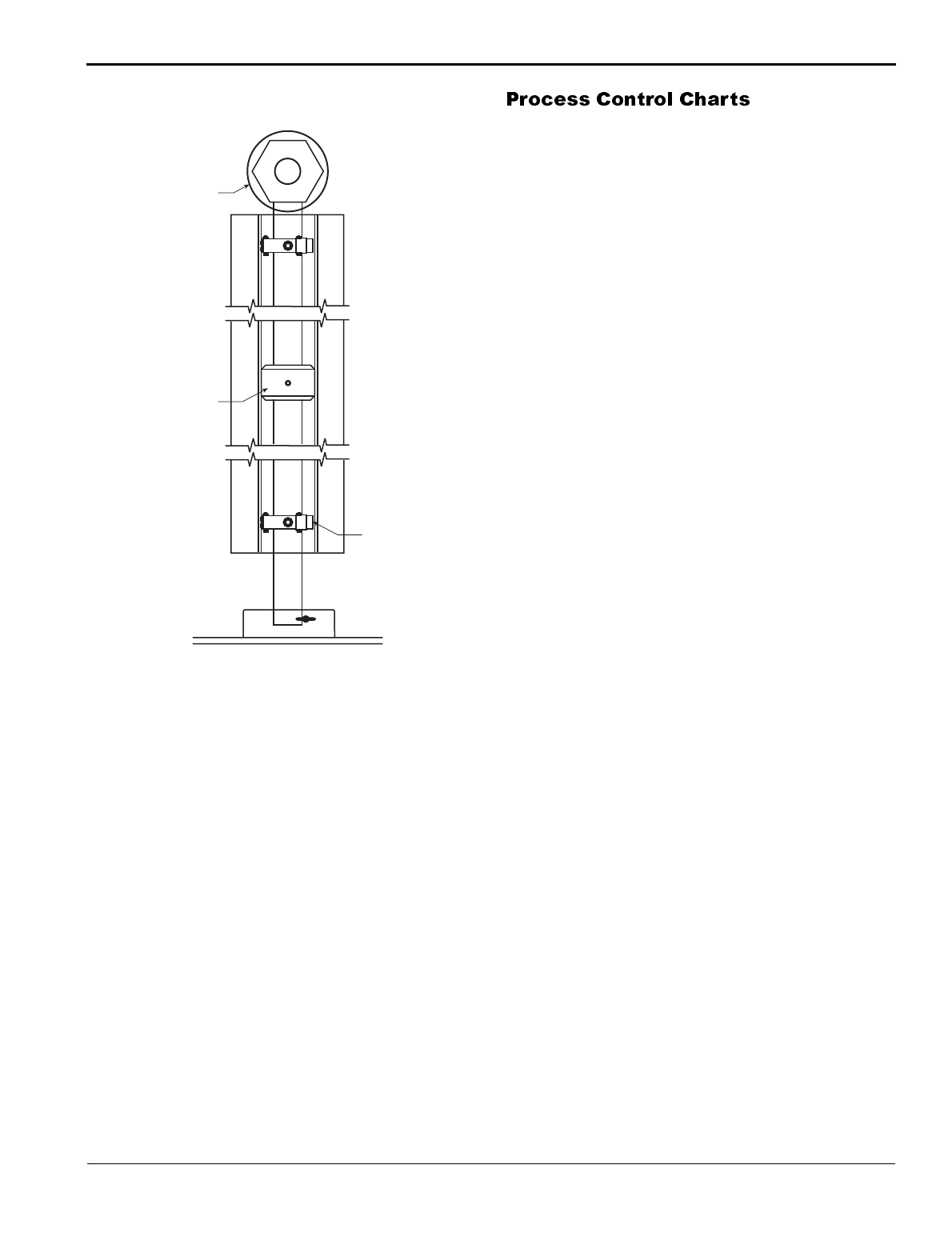
Figure 3-6: Brake Configuration
Process control charts allow you to record the way you
thread film through the machine's rolls and idlers
(called webbing) and the control settings for each prod-
uct and process. Process control charts are an excellent
tool for training new operators. They provide a "road
map" for correct machine setup and operation.
This section contains a blank process control chart and
diagram for the F-60 as well as completed charts for
the basic operations of the laminator.
GBC Pro-Tech laminators respond in a very accurate
and repeatable manner. The charts provide a way to set
up each time, every time for repeatable performance by
assuring that all controls are set to optimum.
The process control charts should be kept in this man-
ual or in a book close to the laminator. Use the machine
to encapsulate the popular charts so they can withstand
food and coffee spills and so they are always available
for ready reference.
☞
NOTE
When trying new products and processes, remember
that GBC Pro-Tech's customer service representatives
are only a phone call away.
The completed process control charts included in this
section are based on Orca-Film and typical prints.
LOWER UNWINDS
Brake
Adjustment
Knob
Core
Support
Core
Chuck

Operation
F-60 Operation and Maintenance Manual
3-6
© GBC Pro-Tech 1998 July
1. See process chart 3-1.
2. Shims: Set to the thickness of the material being
used for mounting.
3. Upper Laminator Roll Pressure: 10–30%.
4. Speed: 3 fpm (1 m/min).
5. Upper Laminator Roll Heat: 240°F (115 °C).
1. Lay the print on the board. Using a tack iron, tack
the leading edge of the print down onto the board
so it is held in place.
2. Put a piece of contact/release paper over the print
and board. Otherwise, adhesive will be applied to
the laminating roll, which can cause damage and
the ink from electrostatic prints will be deposited
on the roll.
3. Feed the print/board package through the nip.
The following procedure is for one-step mounting and
heat-activated laminating using mounting board with
one adhesive side.
1. See process chart 3-2.
2. Mount the film and web as shown in diagram
3-2.
3. Set the nip for the substrate thickness by raising or
lowering the upper main roll using the hand crank.
4. Laminator Roll Pressure: 10–30%.
5. Speed: 3 fpm (1 m/min).
6. Upper Laminator Roll Heat: 240°F (115 °C).
1. Lay the print on the board. Using a tack iron, tack
the leading edge of the print down onto the board
so it is held in place.
2. Feed the print/board package through the nip.
1. See process chart 3-3.
2. Laminating Roll Pressure: 30-40%.
3. Speed: 0-6 fpm (0-3 cpm).
4. Upper Laminator Roll Heat: 230°F (110 °C).
5. Lower Laminator Roll Heat: 32°F (0 °C).
6. Cooling: Optional.
7. Use of the rear wind-up roll for the finished mate-
rial is optional. It is a good procedure for long runs.
Feed the work into the nip with the leading edge tight
and entering the nip evenly from side to side. For thin
paper from electrostatic printers in roll form it is best to
fold over the leading edge approximately 6 inches to
create a square leading edge.
There are several approaches to the mount/laminate
task. It can be accomplished with either hot or cold
laminate film on the top. Also, the second pass for
mounting can be done by feeding from either the front
or back of the laminator.
See process charts 3-4, 3-5A & B, and 3-6A & B for
film mounting instructions and machine adjustments.
1. Run the print through to apply adhesive and lami-
nate.
2. Trim to slightly larger than the desired finished
size.

F-60 Operation and Maintenance Manual
Operation
© GBC Pro-Tech 1998 July
3-7
1. Prepare to put the print through a second time to
mount the print to the substrate - anything from
wood, to Masinote, to Gator foam. Start by setting
the shims to the appropriate spacing for the mate-
rial used.
2. Trim the board to the size of the print.
3. Align the work to the board and ensure an exact fit.
Place weights on the center of the print to make
sure that it does not move relative to the board dur-
ing the next steps.
4. Raise one end of the print and peel back approxi-
mately two inches of the liner to expose the adhe-
sive that was applied to the print in the first pass.
Fold it under.
5. Lay the print back down evenly and extremely flat.
From the center outward, tack the exposed adhe-
sive to the substrate.
6. Position the piece so that the end with the liner
peeled back is facing the nip. Insert the first one
inch of the board into the nip. Very carefully wrap
the print back and over the top laminating roll. Be
sure there are no wrinkles in the nip area. Carefully
peel off the liner as the board progresses through
the laminator.
7. Trim the piece to the finished size.
Operation
F-60 Operation and Maintenance Manual
3-8
© GBC Pro-Tech 1998 July
352&(66&21752/&+$57
Product: _________________________ Process: ___________________________ Date: ________________
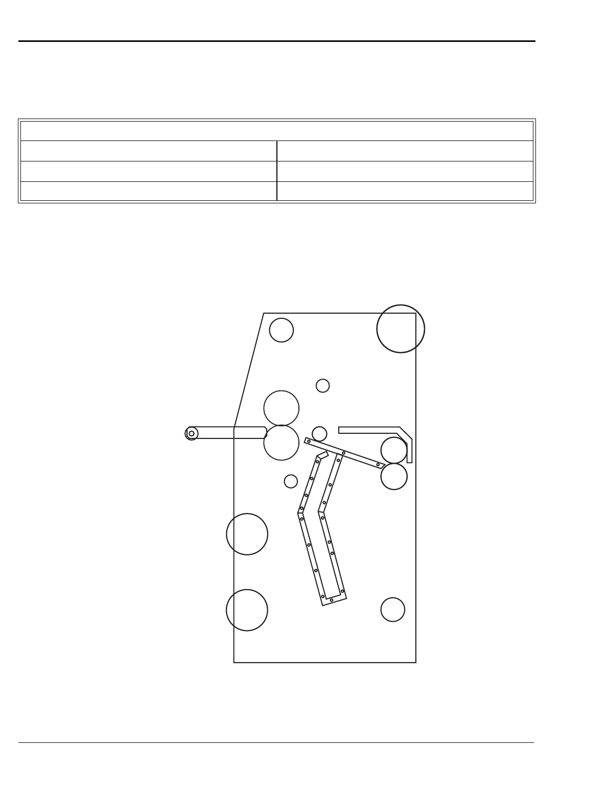
352&(66&21752/',$*5$0
Identification Diagram
FRONT CONTROL SETTINGS
Speed:
Reverse/Forward:
Roll Pressure:
Top Heater:
Cooling:
Bottom Heater:
LM
U
R
F
U
(F) Fixed Idler
(RI) Removable Idler
(U) Unwind Shaft
(R) Rewind
(UM) Upper Main Roll
(LM) Lower Main Roll
(UP) Upper Pull Roll
(LP) Lower Pull Roll
UP
F
RI
UM
LP
UR
F-60 Operation and Maintenance Manual
Operation
© GBC Pro-Tech 1998 July
3-9
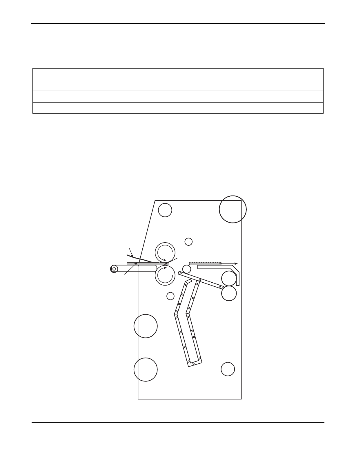
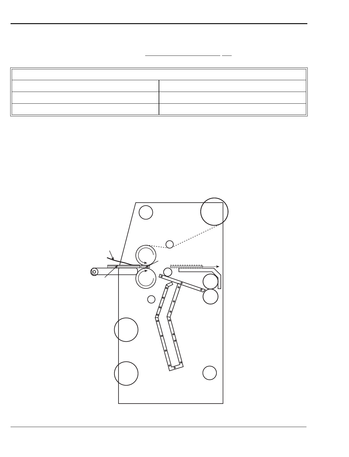
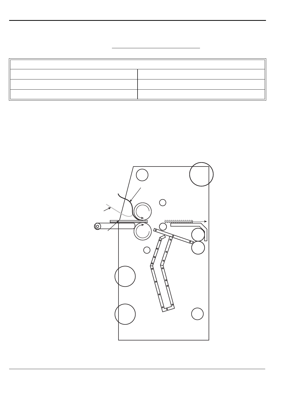
352&(66&21752/&+$57
Product:_________________________ Process: One Pass Mounting __________ Date:________________
352&(66&21752/',$*5$0
One Pass Mounting
☞
NOTE
Guard is removed for this operation. Use automatic slow roll speed (3 ft/min). Footswitch may be used.
FRONT CONTROL SETTINGS
Speed: 2-3 fpm (60-90 cpm)
Reverse/Forward: Forward
Roll Pressure: Trial
Top Heater: 240 ºF (115 ºC)
Cooling: Off
Bottom Heater: Off
Printed
Image
Falcon
Board
Leader
Board
Operation
F-60 Operation and Maintenance Manual
3-10
© GBC Pro-Tech 1998 July
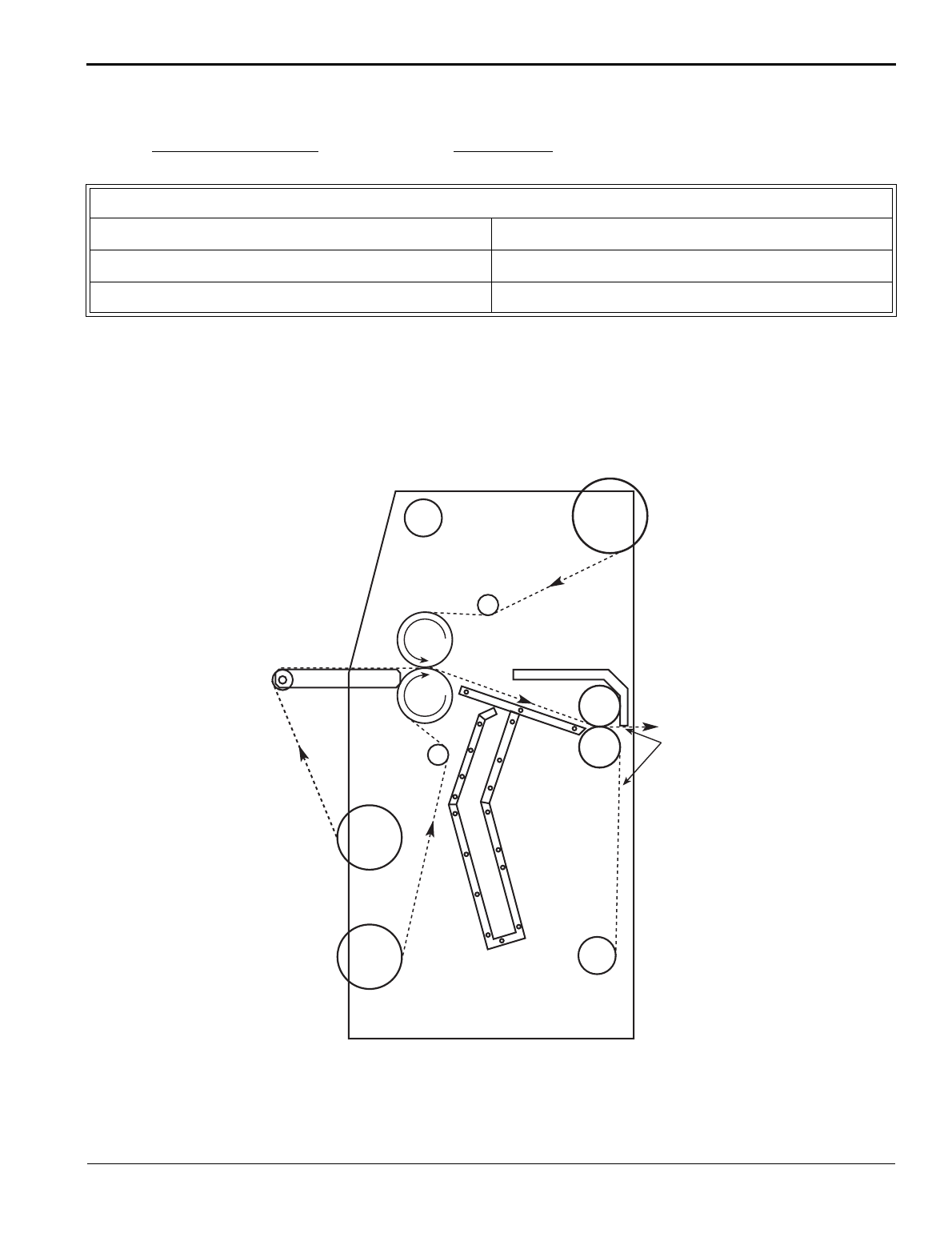
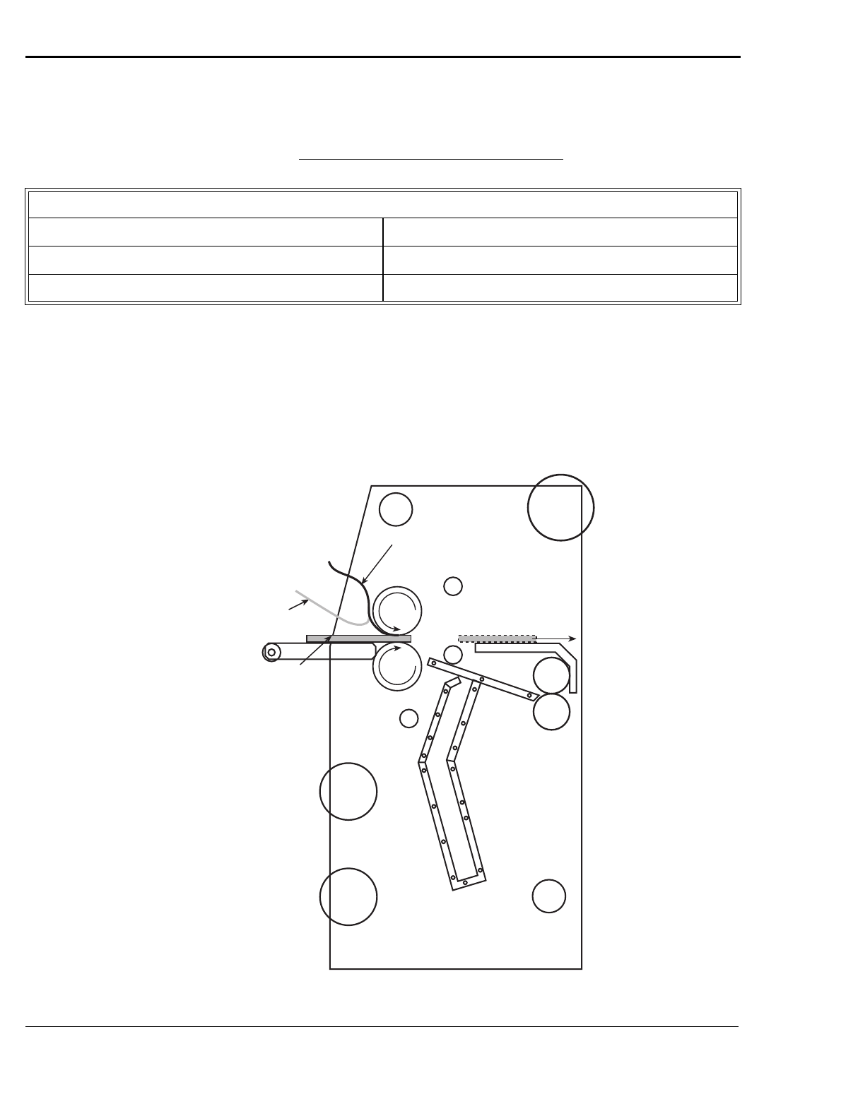
352&(66&21752/&+$57
Product: _________________________ Process: One Pass Mount & Laminate ___ Date: ________________
352&(66&21752/',$*5$0
One Pass Mount and Laminate
☞
NOTE
Guard is removed for this operation. Use automatic slow roll speed (3 ft/min). Footswitch may be used.
FRONT CONTROL SETTINGS
Speed: 1-2 fpm (30-60 cpm)
Reverse/Forward: Forward
Roll Pressure: Trial
Top Heater: 240 ºF (115 ºC)
Cooling: Off
Bottom Heater: Off
Printed
Image
Falcon
Board
Leader
Board
F-60 Operation and Maintenance Manual
Operation
© GBC Pro-Tech 1998 July
3-11
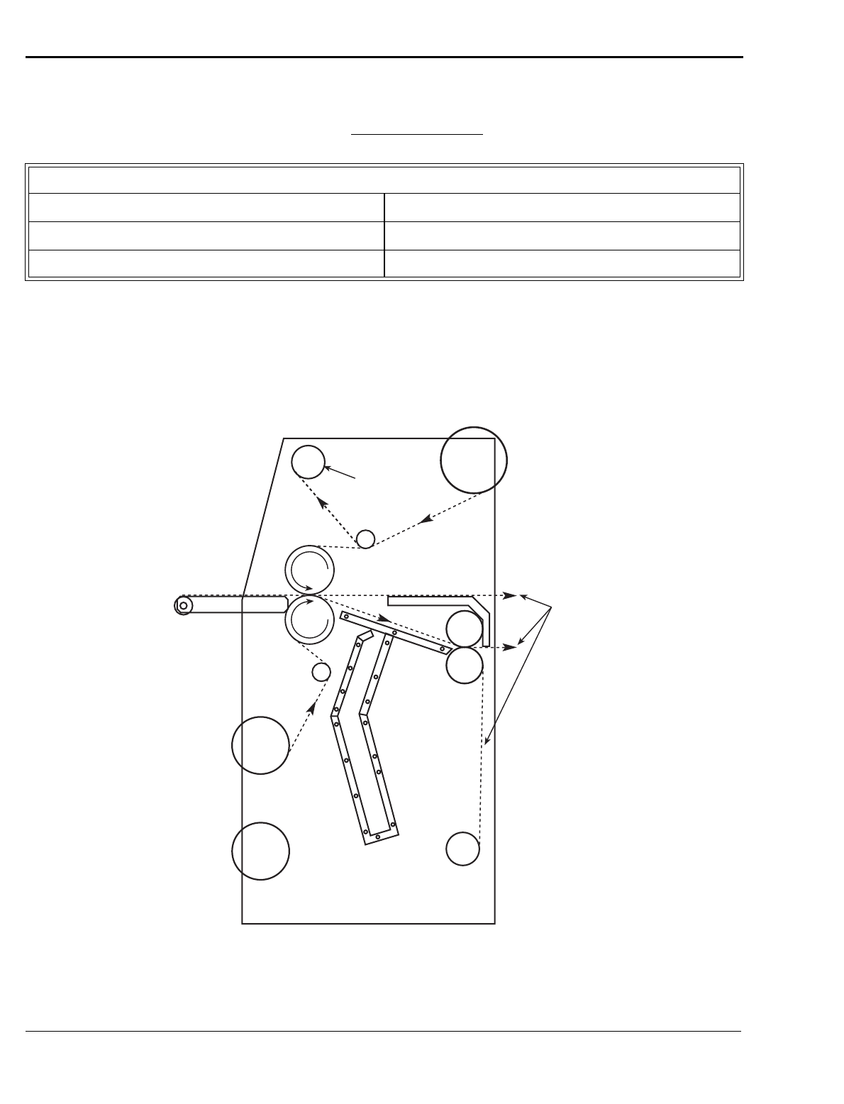
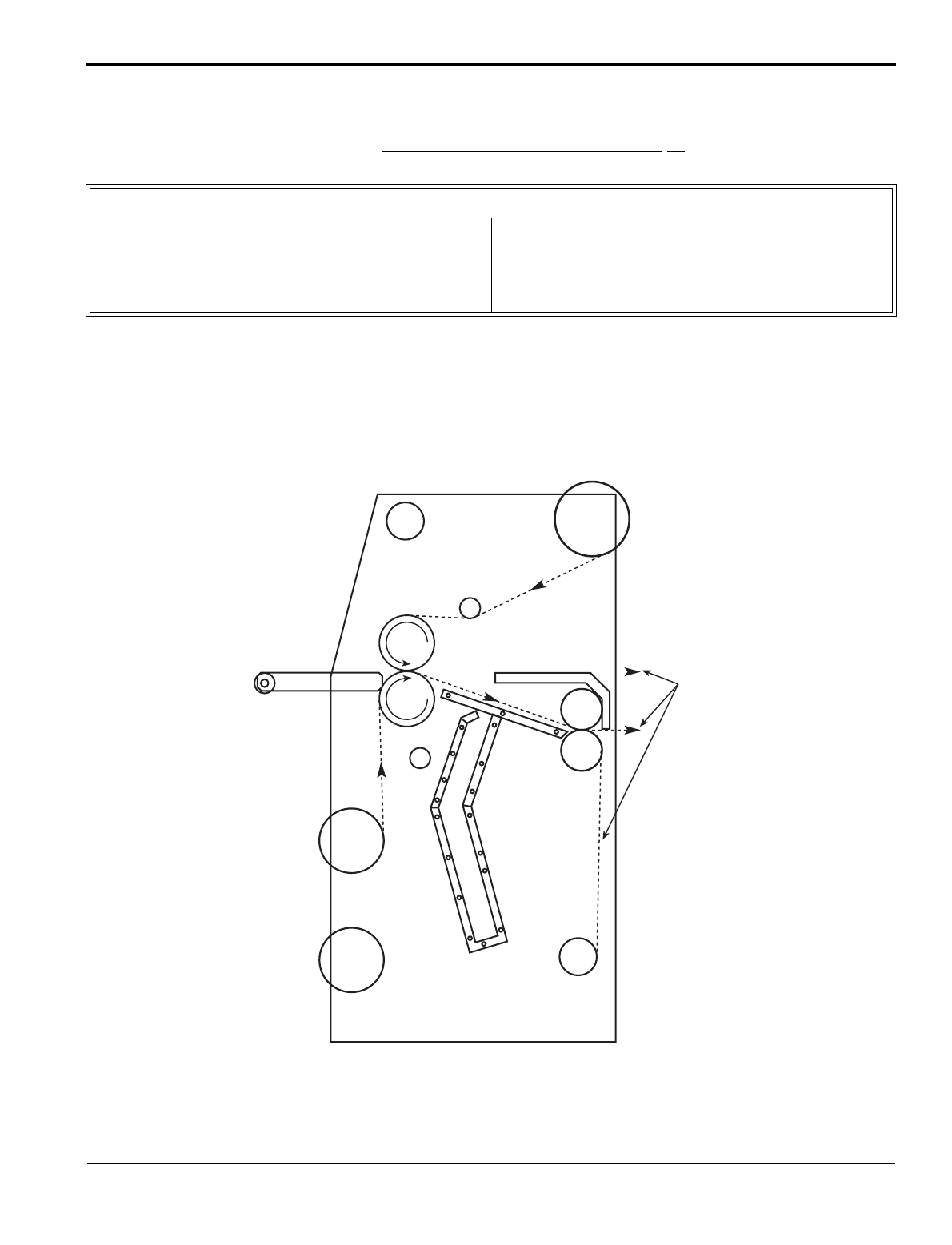
352&(66&21752/&+$57
Product: 3 Mil Gloss/3Mil Gloss _____ Process: Encapsulation ______________ Date:________________
352&(66&21752/',$*5$0
Encapsulation
FRONT CONTROL SETTINGS
Speed: 0-6 fpm (0-180 cpm)
Reverse/Forward: Forward
Roll Pressure: 30-60%
Top Heater: 230 ºF (110 ºC)
Cooling: Optional
Bottom Heater: 230 ºF (110 ºC)
Use
Either
Path
Operation
F-60 Operation and Maintenance Manual
3-12
© GBC Pro-Tech 1998 July
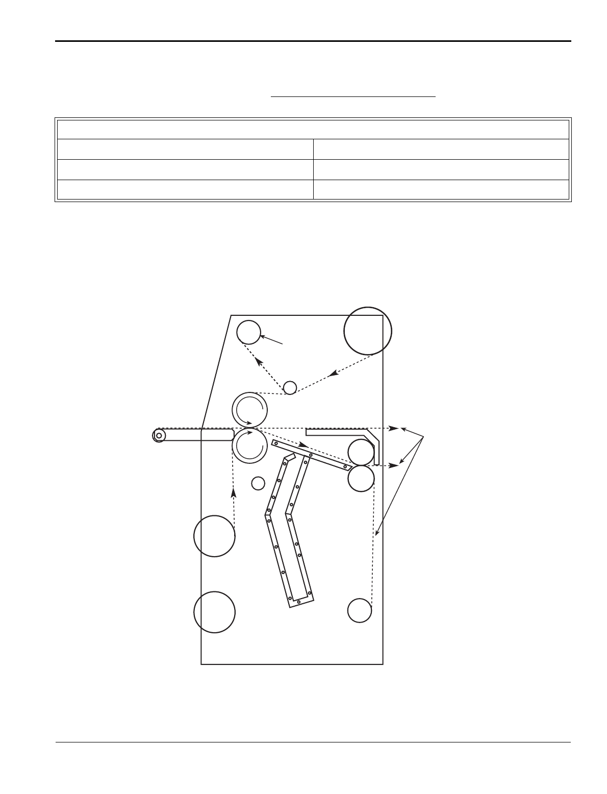
352&(66&21752/&+$57
Product: _________________________ Process: Cold Overlamination _________ Date: ________________
352&(66&21752/',$*5$0
Cold Overlamination
FRONT CONTROL SETTINGS
Speed: 0-6 fpm (0-180 cpm)
Reverse/Forward: Forward
Roll Pressure: 30-60%
Top Heater: 105 ºF (40 ºC)
Cooling: Off
Bottom Heater: 32 ºF (0 ºC)
Pro
Gloss
Craft
Paper
Release
Paper
Rewind
Use
Any
Path
F-60 Operation and Maintenance Manual
Operation
© GBC Pro-Tech 1998 July
3-13
352&(66&21752/&+$57$
Product:______________________ Process: Cold Mount & Laminate (First Pass) Date:________________
352&(66&21752/',$*5$0$
Cold Mount and Laminate (First Pass)
FRONT CONTROL SETTINGS
Speed: 0-6 fpm (180 cpm)
Reverse/Forward: Forward
Roll Pressure: 30-60%
Top Heater: 105 ºF (40 ºC)
Cooling: Off
Bottom Heater: 32 ºF (0 ºC)
Use
Any
Path
Pro
Gloss
Pro
Mount
Release
Paper
Rewind
Operation
F-60 Operation and Maintenance Manual
3-14
© GBC Pro-Tech 1998 July
352&(66&21752/&+$57%
Product: ____________________ Process: Cold Mount & Laminate (Second Pass) Date: ________________
352&(66&21752/',$*5$0%
Cold Mount and Laminate (Second Pass)
☞
NOTE
Guard is removed for this operation. Use footswitch to load, then accelerate materials through rolls.
FRONT CONTROL SETTINGS
Speed: 0-6 fpm (0-180 cpm)
Reverse/Forward: Forward
Roll Pressure: Trial
Top Heater: 32-105 ºF (0-40 ºC)
Cooling: Off
Bottom Heater: 32 ºF (0 ºC)
Hold
Encapsulated
Image
Release Liner
(Peel prior to nip)
Foam
Core
F-60 Operation and Maintenance Manual
Operation
© GBC Pro-Tech 1998 July
3-15
352&(66&21752/&+$57$
Product:_________________ Process: Mount & Hot Overlaminate (First Pass) __ Date:________________
352&(66&21752/',$*5$0$
Mount and Hot Overlaminate (First Pass)
FRONT CONTROL SETTINGS
Speed: 0-6 fpm (0-180 cpm)
Reverse/Forward: Forward
Roll Pressure: 30-60%
Top Heater: 230 ºF (110 ºC)
Cooling: Optional
Bottom Heater: 32 ºF (0 ºC)
Use
Any
Path
3 Mil
Gloss
Pro
Mount
Operation
F-60 Operation and Maintenance Manual
3-16
© GBC Pro-Tech 1998 July
352&(66&21752/&+$57%
Product: __________________ Process: Mount & Hot Overlaminate (Second Pass) Date: ________________
352&(66&21752/',$*5$0%
Mount and Hot Overlaminate (Second Pass)
☞
NOTE
Guard is removed for this operation. Use footswitch to load, then accelerate materials through rolls.
FRONT CONTROL SETTINGS
Speed : 0-6 fpm (0-180 cpm)
Reverse/Forward: Forward
Roll Pressure: Trial
Top Heater: 32-105 ºF (0-40 ºC)
Cooling: Off
Bottom Heater: 32 ºF (0 ºC)
Hold
Encapsulated
Image
Release Liner
(Peel prior to nip)
Foam
Core
F-60 Operation and Maintenance Manual
Maintenance and Troubleshooting
© GBC Pro-Tech 1998 July
4-1
GBC Pro-Tech laminators require minimal mainte-
nance. However, regular maintenance is essential to
keep any piece of precision machinery at peak perfor-
mance. A maintenance schedule and a section of proce-
dures are included in this section.
Table 4-1: Maintenance Schedule
Tools required:
• Adhesive coated board
• 80% isopropyl alcohol (or dishwashing detergent)
• Rubber cement eraser
• Several 100% lint free paper or cotton terry cloths
• Protective rubber gloves
To remove heat activated adhesive from laminator
rolls:
WARNING
While the laminator is still at normal operating temper-
ature (200-250 ºF), put on the rubber gloves and, using
a rubber cement eraser, remove any heat activated
adhesive from the rolls. Use “footswitch mode” and
slow speed to rotate the rolls in reverse.
CAUTION
CAUTION
WARNING
Daily
• Clean the rolls
• Inspect the electrical cord for dam-
age
• Inspect the footswitch cord for dam-
age
Monthly
• Adjust the nip
• Check the chain tension
• Inspect the area around the laminator
for possible hazards (dust buildup,
combustible items stored too close,
etc.)
Every Six
Months
• Lubricate the grease fittings and
chain
• Check wire termination tightness
Exercise extreme caution while cleaning the
laminator. You can be caught in the turning rolls
and crushed or burned.
If silicone adhesive contacts the upper or lower
roll, remove it IMMEDIATELY using a rubber
cement eraser. It can harden within an hour and
ruin the roll.
Do NOT pick or pull heat activated adhesive off
the rolls when they are cold. You can cause
irreparable damage to the laminating rolls.
Do not use compressed air to clean the machine.
Blowing debris can be forced into places where it
will later ignite or short electric circuits.
Maintenance and Troubleshooting
F-60 Operation and Maintenance Manual
4-2
© GBC Pro-Tech 1998 July
To clean beads of adhesive, dust and dirt from the
rolls:
1. Allow the laminator to cool slightly to no higher
than 110ºF (43ºC).
2. Set the FWD/REV switch to the REV position.
3. Clean the rolls using a moderate amount of 80%
isopropyl alcohol on a cotton terry cloth.
CAUTION
WARNING
CAUTION
4. With the laminator rolls no hotter than 110ºF,
remove dust and dirt from the silicone laminating
rolls by running an adhesive-coated board through
the laminator. Be sure to set the nip for the thick-
ness of the board used.
5. Allow the laminator to cool.
To clean the cabinet and covers:
WARNING
1. Using a damp cotton terry cloth (water only), clean
the exterior of the laminator.
WARNING
Use the minimum amount of pressure necessary
to clean the rolls. You can destroy the silicone
layer on the rolls by pressing to hard or
scrubbing too long in one spot.
Exercise care when cleaning the rolls with 80%
isopropyl alcohol:
• Use only in a well ventilated area.
• Wear rubber gloves.
• Use only on cool rolls.
Cleaning heated rolls can ignite the fumes.
Use only 80% isopropyl alcohol or a rubber
cement eraser to clean the laminating rolls.
Harsh chemicals like toluene, acetone or MEK
destroy the silicone covering of the rolls.
Remove and lockout power from the laminator
while you are performing this procedure. You
could be severely shocked, electrocuted, or get
your fingers caught in the drive mechanisms.
Do not use liquid or aerosol cleaners on the
laminator. Do not spill liquid of any kind on the
laminator. You can be severely shocked,
electrocuted or cause a fire. Use only a damp
cloth for cleaning.
F-60 Operation and Maintenance Manual
Maintenance and Troubleshooting
© GBC Pro-Tech 1998 July
4-3
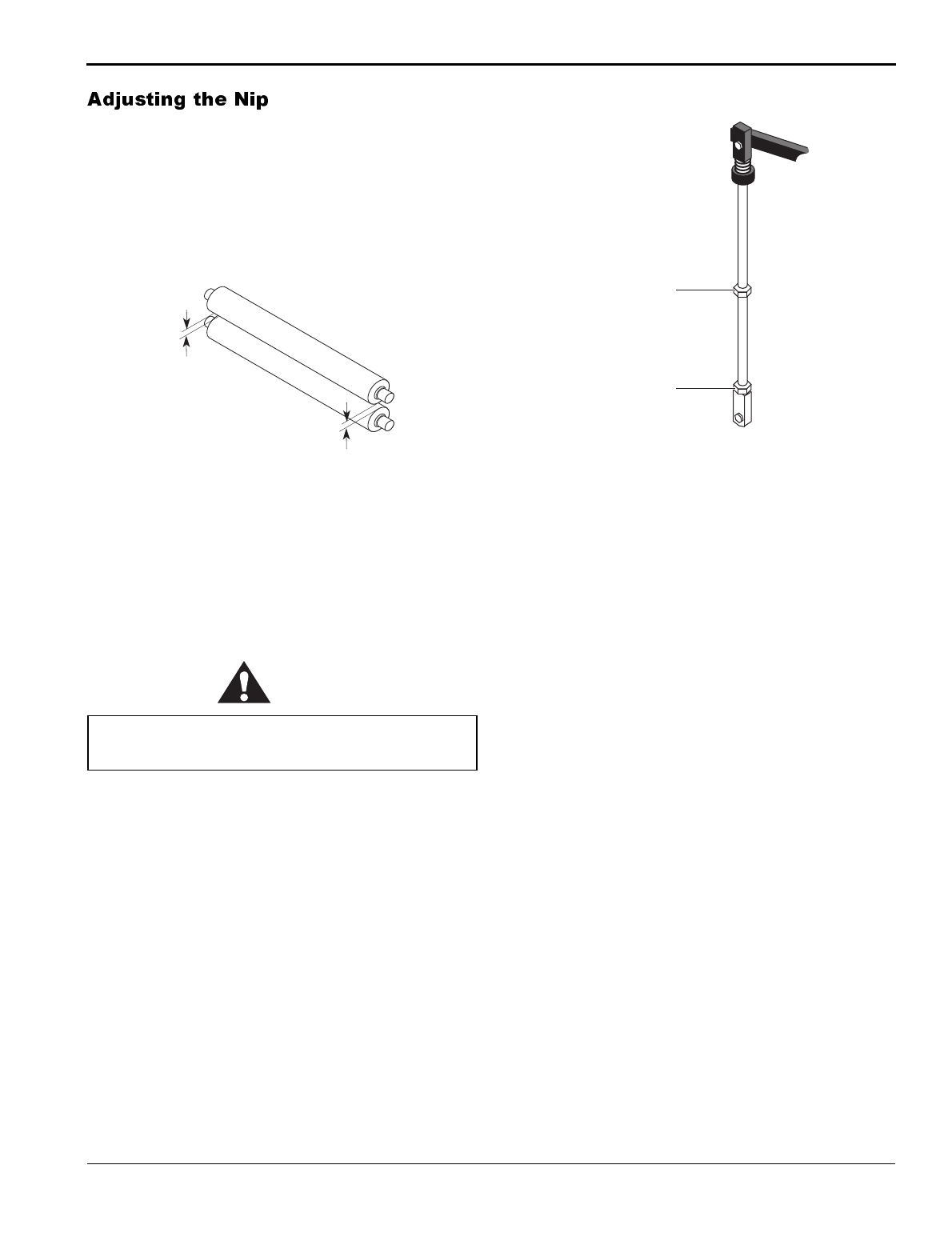
The gap between two rolls is called the nip.
The purpose of adjusting the nip is to ensure continu-
ous contact between the rolls as the media is drawn
through the machine. This procedure must be done reg-
ularly for the main rolls. It is not necessary to set the
nip on the pull rolls.
Figure 4-1: Properly Set Nip
Tools required:
•1/8" hex wrench
• ¾" hex wrench
To adjust the main roll nip:
CAUTION
1. Remove the left side cabinet cover with the 1/8"
hex wrench by removing the eight screws holding
the cover in place. Gently rotate the cover around
the clutch knob to allow access to the roll lift sys-
tem.
2. Lower the upper main roll so that there is a small
visible gap between it and the lower main roll.
3. Loosen the ¾" jam nut securing the lift assembly
bolt. Adjust the nip by rotating the lift assembly
bolt clockwise to raise the end being adjusted and
counterclockwise to lower it.
Figure 4-2: Nip Setting Assembly
4. Adjust the nip so that there is an even line of light
across the width of the rolls.
5. Secure the jam nut on the lift assembly bolt.
6. Replace the cabinet cover.
The main roll must be at room temperature to
achieve a proper nip setting.
Properly Set Nip
(Distance Between
Rolls is Equal)
Lift
Assembly
Bolt
Jam
Nut
Maintenance and Troubleshooting
F-60 Operation and Maintenance Manual
4-4
© GBC Pro-Tech 1998 July
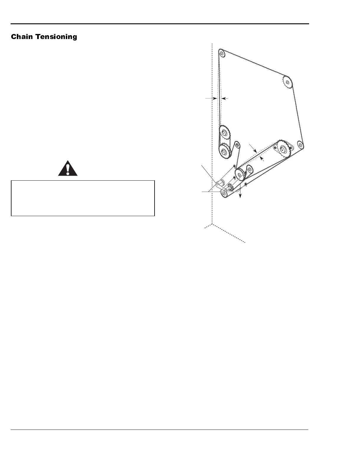
Smaller chain tensioning adjustments on the F-60 Lam-
inator are handled by a secondary chain tensioner, how-
ever, when installing a new chain or when the chain
tension is more seriously out of adjustment, use the fol-
lowing procedure to adjust the chain tension.
Tools required:
•1/8" hex wrench
•3/16" hex wrench
• Screwdriver
To adjust the chain tension:
WARNING
1. Remove the drive side cabinet cover using the 1/8"
hex wrench by removing the eight screws holding
the cover in place. Gently rotate the cover around
the clutch knob to allow access to the drive system
(chain).
2. Loosen the secondary chain tensioner on the sec-
ondary drive chain. The tensioner should, at this
point, not be engaging its respective chain.
3. Loosen all four motor mount bolts using the 3/16"
hex wrench as shown in the figure below. The
motor should just move freely within the slots.
Figure 4-3: Adjusting the Chain Tension
4. Using a screwdriver, apply a small amount of
downward pressure on the motor by prying against
the inside of the side frame until there is ¼" to ½"
play in the chain.
5. Tighten the mounting bolts while maintaining the
downward pressure on the motor.
6. Engage the secondary chain tensioner and apply
pressure until its chain exhibits similar tension to
the primary chain tension.
7. Replace the cabinet cover and reapply power to the
laminator.
Remove and lockout power from the laminator
while you are performing this procedure. You
could be severely shocked, electrocuted, or get
your fingers caught in the drive mechanisms.
Automatic
Chain
Tensioner
Loosen
Motor Mount
Bolts Downward
Force Tightens
Chain
1/4" to
1/2" Play
1/4" to
1/2" Play
F-60 Operation and Maintenance Manual
Maintenance and Troubleshooting
© GBC Pro-Tech 1998 July
4-5
Tools required:
•1/8" hex wrench
• High temperature grease or lithium grease
• Grease gun
To lubricate the laminator:
WARNING
WARNING
1. Remove the drive and control side cabinet covers
using the 1/8" hex wrench by removing the eight
screws holding each cover in place. Gently rotate
the cover around the clutch knob to allow access to
the lubrication points.
2. Using the grease gun, lubricate each grease fitting
with one squirt of high temperature grease.
3. Lubricate the chain using a soft cloth and automo-
tive oil.
4. Replace the cabinet covers, close the safety shields
and reapply power to the laminator.
For machine parts and technical service in North
America, please call: 1-800-790-7787. Please provide
serial number when calling for service. In Europe,
please call: +44 (0) 1844 202 440 or fax: +44 (0) 1844
202 441.
For film and application questions in North America,
please call 1-800-236-8843. In Europe, please call: +44
(0) 1844 202 440 or fax: +44 (0) 1844 202 441.
Do not lubricate the laminator when it is hot. You
can be burned.
Remove and lockout power from the laminator
while you are performing this procedure. You
could be severely shocked, electrocuted, or get
your fingers caught in the drive mechanisms.
Maintenance and Troubleshooting
F-60 Operation and Maintenance Manual
4-6
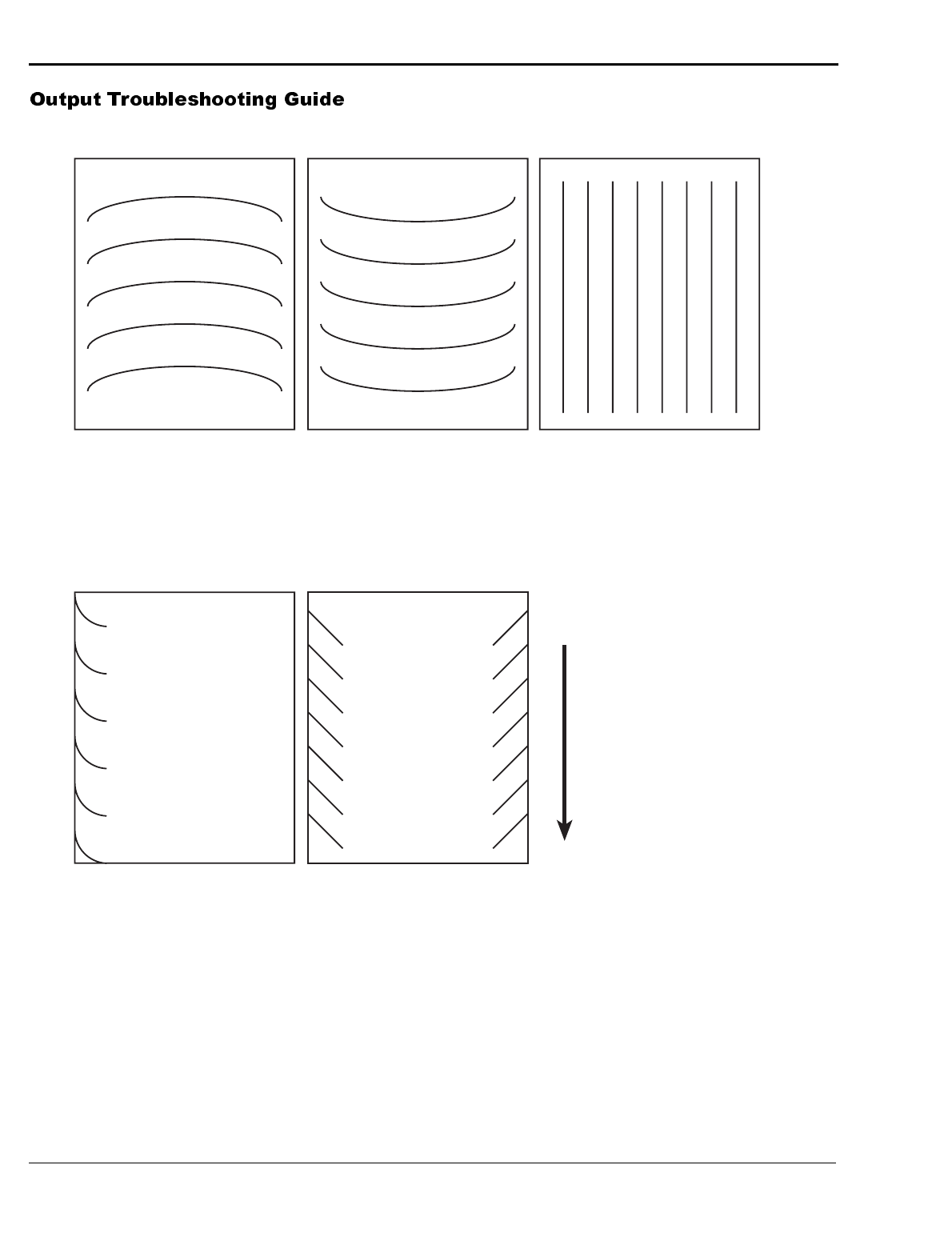
© GBC Pro-Tech 1998 July
Problem:
D waves in the image, not in the
laminate.
Hints:
• Check paper tension.
• Check relative moisture content
of the paper.
Problem:
D waves in the laminate.
Hints:
• Increase clutch tension.
• Check roll pressures.
• Check nip settings.
Problem:
Straight waves in the output.
Hints:
• Decrease clutch tension.
• Check operational settings for
materials being used.
Problem:
Waves on only one side of the
output.
Hints:
• Check nip settings.
• Check for even paper tension.
Other Common
Problems:
Problem:
Blistering in the image.
Hints:
• Increase speed or lower
the operating
temperature.
Problem:
Coiling of encapsulated
images.
Hints:
• Balance the upper and
lower unwind brake
tension. Make sure
main roll temperatures
are the same. Adjust
cooling fans.
Problem:
Longitudinal waves or
stuttering, jerking, or
excessive noise from the
drive side of the laminator.
Hints:
• Increase chain tension,
decrease unwind brake
tension.
Problem:
Angled waves on the output.
Hints:
• Check for insufficient clutch
tension.
• Check for insufficient main roll
pressure
Feed
Direction
F-60 Operation and Maintenance Manual
Warranty
© GBC Pro-Tech 1998 July
5-1
GBC Pro-Tech Engineering Company, Inc. warrants
the equipment sold is free from defects in material and
workmanship for a period of ninety days (90) from the
date of delivery to the customer. This warranty is the
only warranty made by GBC Pro-Tech and cannot be
modified or amended.
GBC Pro-Tech’s sole and exclusive liability and the
customer’s sole and exclusive remedy under this
warranty shall be, at GBC Pro-Tech’s option, to
repair or replace any such defective part or prod-
uct. These remedies are only available if GBC Pro-
Tech’s examination of the product discloses to GBC
Pro-Tech’s satisfaction that such defects actually
exist and were not caused by misuse, neglect,
attempt to repair, unauthorized alteration or modi-
fication, incorrect line voltage, contaminated air
supply, or by fire, accident, flood, or other hazard.
This warranty specifically does not cover damage to
the laminating rollers caused by knives, razor blades,
other sharp objects, failure caused by adhesives or
improper use of the machine. Warranty repair or
replacement does not extend the warranty beyond the
initial ninety day period from the date of delivery.
CAUTION
THE WARRANTY MADE HEREIN IS IN LIEU OF
ALL OTHER WARRANTIES, EXPRESS OR
IMPLIED, INCLUDING ANY WARRANTY OR
MERCHANTABILITY OR FITNESS FOR A PAR-
TICULAR PURPOSE. GBC PRO-TECH WILL NOT
BE LIABLE FOR PROPERTY DAMAGE OR PER-
SONAL INJURY (UNLESS PRIMARILY CAUSED
BY ITS NEGLIGENCE), LOSS OF PROFIT OR
OTHER INCIDENTAL OR CONSEQUENTIAL
DAMAGES ARISING OUT OF THE USE OR
INABILITY TO USE THE EQUIPMENT.
This warranty specifically does not cover:
1. Damage to the laminating rolls caused by knives,
razor blades, other sharp objects, or failure caused
by adhesives.
2. Damage to the machine caused by lifting, tilting,
and/or any attempt to position the machine other
than rolling on the installed casters on even sur-
faces.
3. Improper use of the machine.
Unauthorized customer alterations will void this
warranty.

Warranty
F-60 Operation and Maintenance Manual
5-2
© GBC Pro-Tech 1998 July
Blank page.
F-60 Operation and Maintenance Manual
Specifications
© GBC Pro-Tech 1998 July
6-1
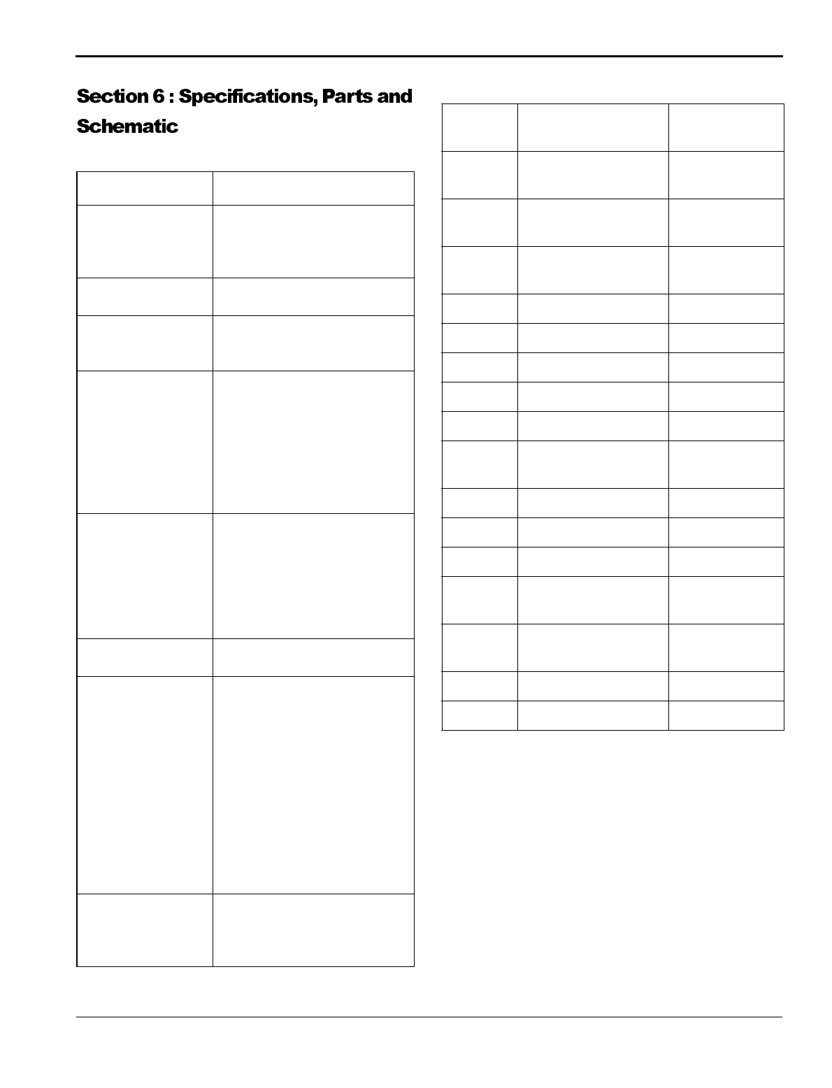
Table 6-1: F-60 Laminator Specifications
Table 6-2: Replacement Parts
Characteristic
Specifications
Dimensions
(L x D x H) Uncrated: 80" x 33" x 57"
(202 x 84 x 145 cm)
Crated: 90" x 44" x 68"
(202 x 84 x 145 cm)
Weight Uncrated: 1200 lbs (544 kg)
Crated :1700 lbs (771 kg)
Laminating Rolls 64" (163 cm) roll face with a
high release surface, upper and
lower rolls internally heated.
Laminating Material Uses pressure sensitive materi-
als up to 62 inches (158 cm)
wide and hot/heat activated
materials up to 61 inches (155
cm) wide on a 3-inch (7.6 cm)
inside diameter core, maxi-
mum roll diameter of 10 inches
(25.4 cm).
Laminating Speeds 0 to 15 fmp (0 to 4.57 mpm)
with variable speed, reversible
action at slow speed (less than 3
ft/min (1 m/min)), start and
stop controlled either through
the instrument panel or with the
variable speed footswitch
Heating Capable of operating tempera-
tures of up to 270 ºF (132 ºC).
Safety Features • Redundant circuit pro-
tected safety shielding
• Mechanical shielding on
infeed
• Slow mode (1 m/min) for
all reverse operations with
beeping warning alarm
• Four emergency stop but-
tons
• Pull rolls contained in an
enclosure to prevent injury
Installation
Requirement 55A single phase, 220/230/240
VAC or, in Europe, 3 Phase,
240/400 VAC with 25 Amps
per phase.
Part
Number Description Recommended
Quantity
001-374 Assembly, Force
Gauge PCB 1
001-505 Assembly, Force
Sensor 1
001-515 Assembly, Control
PCB 1
186-200 Fuse, SB, 3AG, 3A 3
214-313 Switch, Palm, E-stop 1
230-007 Temperature Control 1
425-003 Motor 1
690-059 Roll, Rubber 1
026-004 Flanged Bearing,
Plastic 5/8 2
189-031 Heater, Round 1
230-006 IR Sensor 1
860-014 Tube, Rewind Brake 2
214-005 Microswitch, Safety,
Interlock 1
186-135 Fuse, 250V, 20A,
Ceramic 1
690-052 Roll, Pull, Upper 1
690-053 Roll, Pull, Lower 1

Specifications
F-60 Operation and Maintenance Manual
6-2
© GBC Pro-Tech 1998 July
Blank page.

F-60 Operation and Maintenance Manual
Index
© GBC Pro-Tech 1998 July
7-1
Accessory pack 2-4
Adjusting
nip 4-3
Chain
Lubrication 4-5
Tensioning 4-4
Cleaning 4-1
Controls
front control panel 3-2
Emergency stop buttons 1-1, 2-6, 3-1
Encapsulation 3-6
Environment 2-1
Extension cord 2-1
Film
loading 3-3
positioning 3-4
Footswitch 3-2, 4-1, 6-1
FWD/REV switch 4-2
Grease fittings 4-5
Ground plug 2-1
Heater 2-6
Controller 2-6
Heaters
Installing 2-5
Heating 3-4
Installation requirements 2-1, 6-1
Isopropyl alcohol 4-1
Laminating material 6-1
Laminating rolls 6-1
Laminating speeds 6-1
Leveling 2-5
Lubrication 4-5
Main rolls 4-3
Maintenance schedule 4-1
Motor 2-6, 4-4
Mounting 3-6
Mounting/Laminating 3-6
Nip 1-2, 2-5, 4-1, 4-2, 4-3
Paper 3-4
Power cord 2-1
Power requirement 2-1
Preinstallation checklist 2-1
Pressure
laminator roll 3-3
Process control charts 3-5
Pull roll
clutch adjustment 3-4
raising and lowering 3-4
Resetting the laminator 1-1, 3-1
Riggers 1-3, 2-4
Rubber cement eraser 4-1
Safety features 6-1
Safety information 1-1
Safety labels 1-3
Setup 3-3
Setup procedure 2-5
Specifications
Dimensions 6-1
Laminating material 6-1
Laminating rolls 6-1
Laminating speeds 6-1
Weight 6-1
Startup checklist 2-6
Technical support
Call 1-800-236-8843 4-5
Two-pass mount and laminate 3-6

Index
F-60 Operation and Maintenance Manual
7-2
© GBC Pro-Tech 1998 July
Unpacking 2-3
Crate 2-3
Upper main roll 1-3
Warnings and cautions 1-1
Warranty 5-1
