Ge Appliances General Electric Microwave Oven Jvm2070 H Users Manual
31-9111 Ge - Microwave Oven - Otr - Jvm2070 H 31-9111 GE - Microwave Oven - OTR - JVM2070_H 31-9111 GE - Microwave Oven - OTR - JVM2070_H GE, Camco, Hotpoint, Mofat applianceservicesecretsmembership.com_manuals
General Electric Microwave Oven JVM2070_H jvm2070_31-9111_sm
JVM2070_H to the manual fad02203-3b63-4556-99d4-077ad55ca3f3
2015-01-23
: Ge-Appliances Ge-Appliances-General-Electric-Microwave-Oven-Jvm2070-H-Users-Manual-255658 ge-appliances-general-electric-microwave-oven-jvm2070-h-users-manual-255658 ge-appliances pdf
Open the PDF directly: View PDF ![]() .
.
Page Count: 33
MODEL SERIES:
JVM2070_H
TECHNICAL SERVICE GUIDE
GE Consumer & Industrial
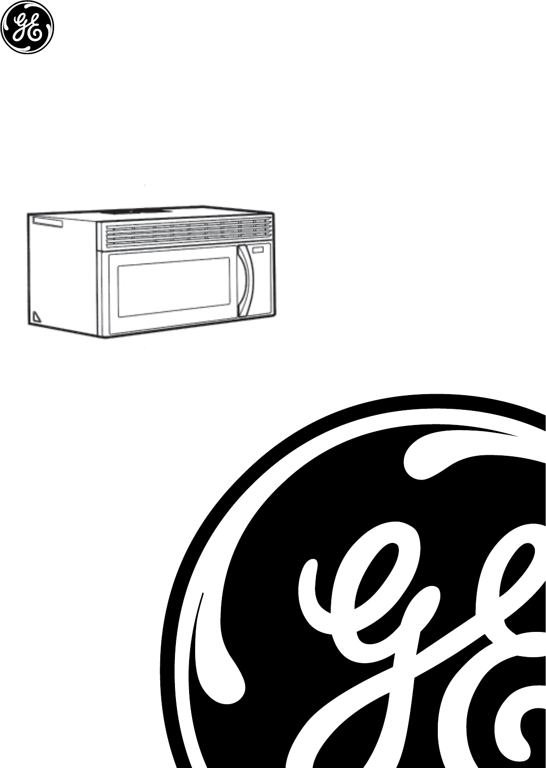
Over the Range
Microwave Oven
PUB # 31-9111 2/04

– 2 –
IMPORTANT SAFETY NOTICE
The information in this service guide is intended for use by
individuals possessing adequate backgrounds of electrical,
electronic, and mechanical experience. Any attempt to repair a
major appliance may result in personal injury and property
damage. The manufacturer or seller cannot be responsible for the
interpretation of this information, nor can it assume any liability in
connection with its use.
WARNING
To avoid personal injury, disconnect power before servicing this
product. If electrical power is required for diagnosis or test
purposes, disconnect the power immediately after performing the
necessary checks.
RECONNECT ALL GROUNDING DEVICES
If grounding wires, screws, straps, clips, nuts, or washers used
to complete a path to ground are removed for service, they must
be returned to their original position and properly fastened.
!
GE Consumer & Industrial
Technical Service Guide
Copyright © 2004
All rights reserved. This service guide may not be reproduced in whole or in part
in any form without written permission from the General Electric Company.
– 3 –
PRECAUTIONS TO BE OBSERVED BEFORE AND DURING
SERVICING TO AVOID POSSIBLE EXPOSURE TO EXCESSIVE
MICROWAVE ENERGY.
A. DO NOT OPERATE OR ALLOW THE OVEN TO BE OPERATED
WITH THE DOOR OPEN.
B. IF THE OVEN OPERATES WITH THE DOOR OPEN, INSTRUCT
THE USER NOT TO OPERATE THE OVEN AND CONTACT THE
MANUFACTURER IMMEDIATELY.
C. MAKE THE FOLLOWING SAFETY CHECKS ON ALL OVENS TO
BE SERVICED BEFORE ACTIVATING THE MAGNETRON OR
OTHER MICROWAVE SOURCE, AND MAKE REPAIRS AS
NECESSARY:
1. INTERLOCK OPERATION.
2. PROPER DOOR CLOSING.
3. SEAL AND SEALING SURFACES (ARCING, WEAR AND
OTHER DAMAGE).
4. DAMAGE TO OR LOOSENING OF HINGES AND LATCHES.
5. EVIDENCE OF DROPPING OR ABUSE.
D. BEFORE TURNING ON MICROWAVE POWER FOR ANY TEST
OR INSPECTION WITHIN THE MICROWAVE GENERATING
COMPARTMENTS, CHECK THE MAGNETRON, WAVE GUIDE
OR TRANSMISSION LINE AND CAVITY FOR PROPER
ALIGNMENT, INTEGRITY AND CONNECTIONS.
E. ANY DEFECTIVE OR MISADJUSTED COMPONENTS IN THE
INTERLOCK MONITOR, DOOR SEAL AND MICROWAVE
GENERATION AND TRANSMISSION SYSTEMS SHALL BE
REPAIRED, REPLACED OR ADJUSTED BY PROCEDURE
DESCRIBED IN THIS MANUAL BEFORE THE OVEN IS
RELEASED TO THE OWNER.
F. A MICROWAVE LEAKAGE CHECK TO VERIFY COMPLIANCE
WITH THE FEDERAL PERFORMANCE STANDARD SHOULD
BE PERFORMED ON EACH OVEN PRIOR TO RELEASE TO
THE OWNER.

– 4 –
Bottom and Hood Thermal Cutout (TCO) ....................................................................................................18
Cavity Thermal Cutout (TCO) ......................................................................................................................13
Component Locator Views .......................................................................................................................... 7
Components................................................................................................................................................ 9
Control Features ......................................................................................................................................... 6
Control Panel .............................................................................................................................................16
Control Performance Test ...........................................................................................................................20
Cooling Fan and Motor ...............................................................................................................................12
Demonstration Mode ..................................................................................................................................21
Diagnostics Test ........................................................................................................................................21
Door Interlock Switches .............................................................................................................................16
Exhaust Fan ............................................................................................................................................... 9
Fuses ........................................................................................................................................................13
Gas Sensor................................................................................................................................................14
Hidden Vent Motor .....................................................................................................................................15
High Voltage Capacitor ...............................................................................................................................18
Illustrated Parts Catalog .............................................................................................................................30
Interior Light ...............................................................................................................................................15
Magnetron ..................................................................................................................................................14
Magnetron Thermal Cutout (TCO) ...............................................................................................................13
Microwave Leakage Test ............................................................................................................................22
Microwave Removal and Component Access .............................................................................................. 9
Nomenclature .............................................................................................................................................. 5
Performance Test .......................................................................................................................................22
Primary Interlock System Test ...................................................................................................................17
Schematic..................................................................................................................................................29
Sensor Test (Quick Test) ............................................................................................................................20
Side Stirrer .................................................................................................................................................10
Side Stirrer Motor .......................................................................................................................................10
Smart Board...............................................................................................................................................23
Strip Circuits ..............................................................................................................................................24
Surface Lamp Assemblies ..........................................................................................................................19
Surface Lamps ...........................................................................................................................................19
Top Stirrer ................................................................................................................................................... 11
Top Stirrer Motor ......................................................................................................................................... 11
Touchscreen Display .................................................................................................................................. 6
Transformer ................................................................................................................................................14
Troubleshooting ..........................................................................................................................................20
Turntable Motor ..........................................................................................................................................18
Warranty ....................................................................................................................................................33
Wiring Diagram ..........................................................................................................................................28
Table of Contents
– 5 –
Product
J = GE Cooking Product
Microwave Oven
V = Over-the-Range Model
Installation
M = Mounts Under Cabinet
Model Number
Nomenclature
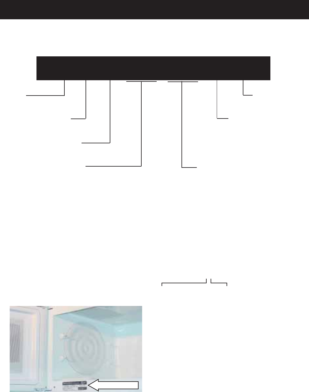
J V M 2 0 7 0 W H
The nomenclature plate is located on the
microwave cabinet inside the door. In
addition to model and serial number, this
plate also shows power ratings.
The Mini-manual is located behind the
hidden vent.
Cavity Size (cu. ft.)
20 = 2.0 cu. ft. Feature Pack
Designates features–the higher
the number, the more features.
Model Year
Designator
Case Color
S = Stainless
W = White
C = Bisque
B = Black
Serial Number
The first two numbers of the serial number
identify the month and year of manufacture.
Example: AG123456S = January, 2004
A - JAN 2005 - H
D - FEB 2004 - G
F - MAR 2003 - F
G - APR 2002 - D
H - MAY 2001 - A
L - JUN 2000 - Z
M - JUL 1999 - V
R - AUG 1998 - T
S - SEP 1997 - S
T - OCT 1996 - R
V - NOV 1995 - M
Z - DEC 1994 - L
The letter designating
the year repeats every
12 years.
Example:
T - 1974
T - 1986
T - 1998
Nomenclature
– 6 –
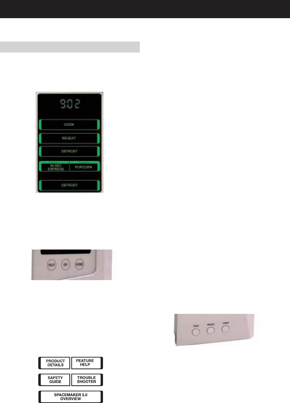
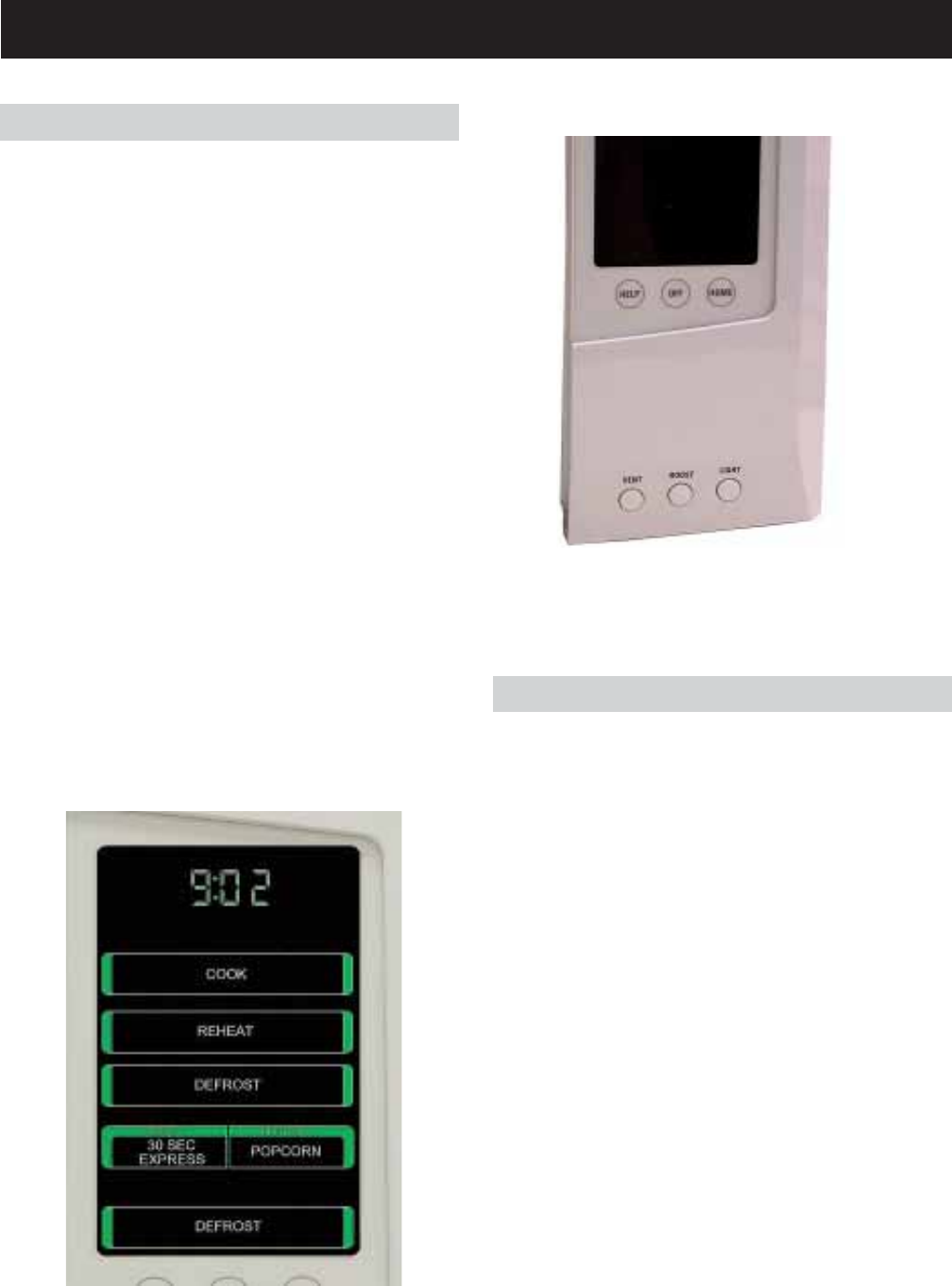
Control Features
After pressing HELP:
• Press PRODUCT DETAILS to find information
concerning your model and serial number.
• Press FEATURE HELP to find help locating
information on the microwave features.
• Press SAFETY GUIDE to find help locating
microwave safety information.
For diagnostics displays, see page 20.
HELP
Pressing HELP from the HOME screen allows
you to locate feature information and helpful hints.
• Press TROUBLESHOOTER to find
troubleshooting tips for common microwave
problems.
• Press SPACEMAKER 2.0 OVERVIEW to find
an overview of the features of your
microwave.
OFF
WARNING: Pressing OFF does not disconnect
the appliance from the power supply.
Pressing OFF while on the HOME screen will put
the touchscreen into standby mode, and the
display will be dark. Press the touchscreen or
HOME, or open the door to “wake up” the display.
Pressing OFF while on any other screen will
cancel the current screen and return the display
to the HOME screen.
HOME
HOME returns the display to the HOME screen
(displayed) at any time. The HOME screen is the
starting point for setting any cooking or defrost
program, or for setting microwave options. If the
touchscreen is dark, press the HOME button to
activate the screen.
VENT
Press VENT once for high fan speed. Press a
second time for medium fan speed, a third time
for low fan speed, and a fourth time to turn the fan
off. Press BOOST for extra fan speed.
BOOST
The BOOST button turns the vent fan on HIGH.
LIGHT
Press LIGHT once for bright light. Press a
second time for the night light. Press a third time
to turn the light off.
Touchscreen Display
The touchscreen display provides the access to
all cook and defrost controls. If the touchscreen is
dark, press the HOME button, the touchscreen,
or open the door to access the menu.
– 7 –
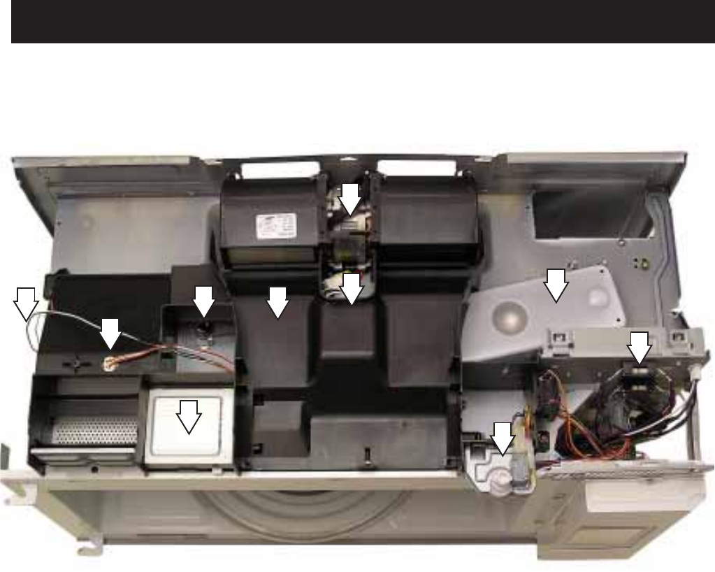
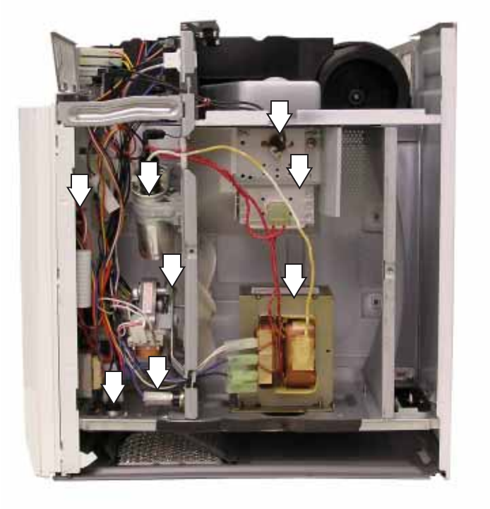
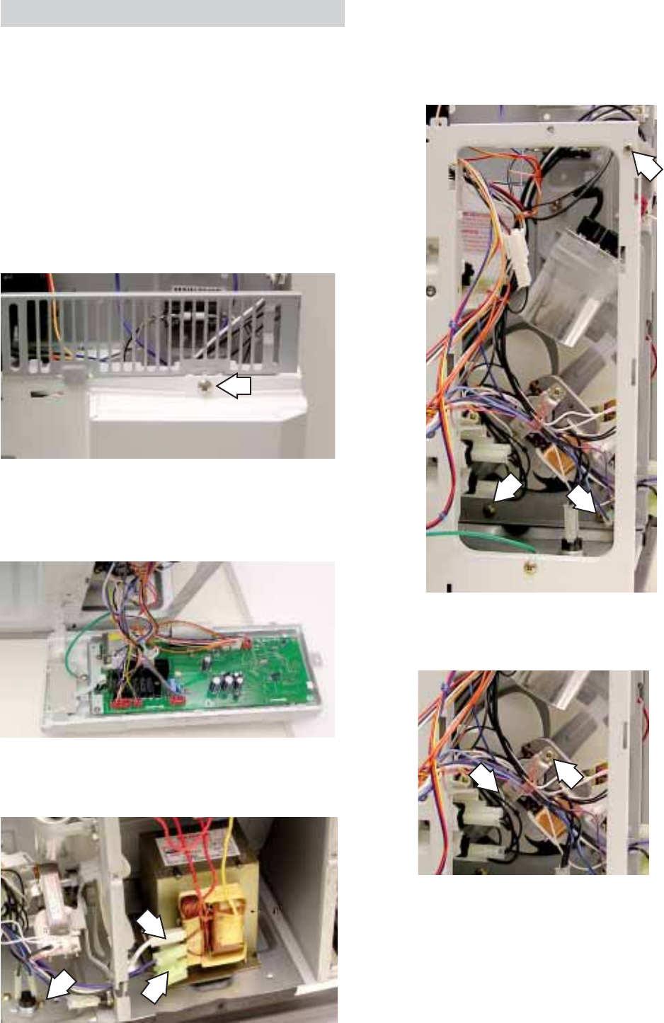
Component Locator Views
1 - Interior Light
2 - Main and HV Transformer Fuses
3 - Hidden Vent Switch and Motor
4 - Vent Fan and Motor
5 - Top Stirrer Motor
6 - Cavity Thermal Cutout (TCO)
7 - Side Stirrer Motor
8 - Magnetron Antenna Waveguide
9 - Vent Tunnel
10 - Gas Sensor
Top View
7
2
3
4
5
6
8
9
10
1
– 8 –
1 - Magnetron
2 - Magnetron Thermal Cutout (TCO)
3 - High Voltage Transformer
4 - Magnetron Cooling Fan Motor and Blade
5 - High Voltage Capacitor
6 - Door Sensing Switch (Primary Interlock and Monitor Switch in plastic mount - not shown)
7 - Bottom Thermal Cutout (TCO)
8 - Hood Thermal Cutout (TCO)
Right Side View
2
1
3
5
4
6
78
– 9 –
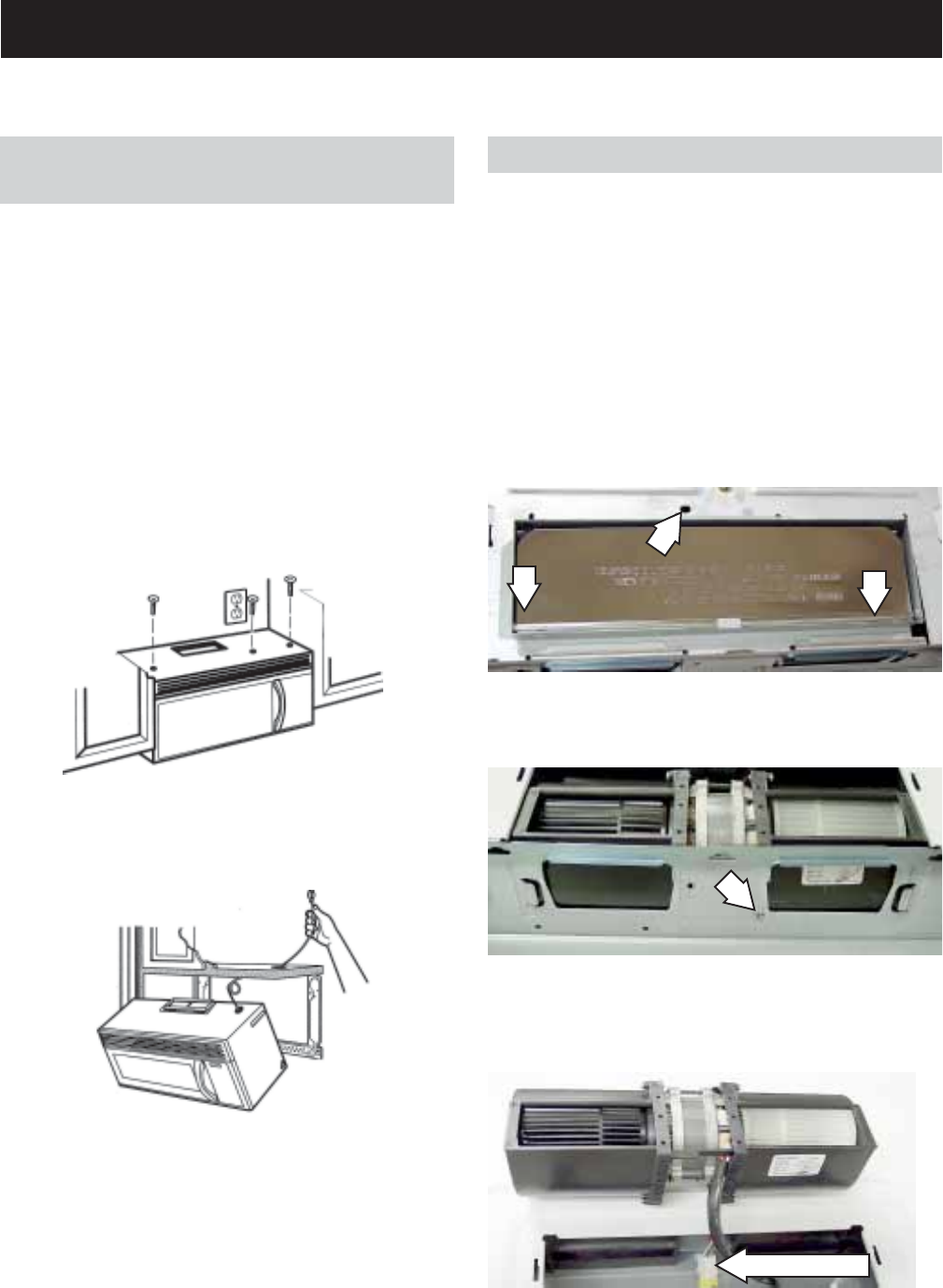
Microwave Removal and Component
Access
Note: Some components can be accessed
without removing the microwave. If the 2 end
screws on top of the outer cover are accessible
(see illustration below), the hidden vent can be
removed without removing the microwave from its
installation.
Note: For easier removal and personal safety, it
is recommended that 2 people remove the
microwave.
Unplug the microwave and remove it from the wall
by removing three screws in the cabinet above
the microwave.
Lift the fan out of the microwave and disconnect
the electrical connector.
Remove the screw holding the fan in place.
Tilt the microwave forward and lift it off the lower
tabs of the rear mounting plate. Route the power
cord through the hole.
Place the microwave on a protected counter or
table.
To remove the cover, remove 2 screws from the
left side, 3 screws from the right side, 5 screws
from the top, 5 screws from the rear, and 2
screws from the bottom of the outer cover.
Open the microwave oven door. Slide the hidden
vent to the left and remove the hidden vent.
Exhaust Fan
Resistance through the exhaust fan from the
power cord (N) to CN03 pin 7 is approximately
28.7 ohms.
Removal
Remove the microwave (see Microwave Removal
and Component Access). Remove the screw on
top of the microwave holding the exhaust adapter
in place, then slide the exhaust adapter to the rear
and remove.
Disconnect
Top View
Components
– 10 –
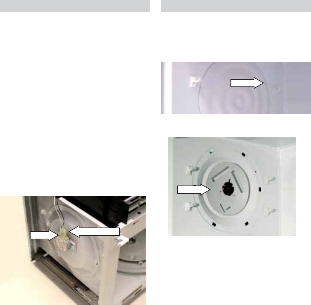
Side Stirrer Motor
The side stirrer motor is located on the left side of
the microwave oven.
Resistance through the side stirrer motor from
the power cord (L) to CN04 pin 5 is approximately
6.7 ohms. Isolated, the side stirrer motor is
approximately 7.0 ohms. The door (primary
interlock) must be closed to complete circuit.
Check motor circuit for 21 VAC when operating.
Removal
Remove the microwave (see Microwave Removal
and Component Access).
Disconnect the wire connector to the side stirrer
motor. Remove the screw and turn the motor 1/8
turn CCW.
Note: When installing stirrer motor, be sure the
locating pin is inserted in the motor mounting tab
and the side stirrer is resting on the support in the
cover prior to installing the screw.
Disconnect
Screw
Side Stirrer
Removal
Open the oven door. Pull the plastic rivet out of the
stirrer cover. Rotate the stirrer cover CCW until it
stops and remove the stirrer cover.
Rivet
Stirrer
Note: When assembling, assure that the stirrer
rides on the support in the cover.
Remove the stirrer.
– 11 –
Disconnect the electrical connector from the
motor. Remove 2 screws that hold the motor in
place and remove the motor.
Top Stirrer Motor
Resistance through the top stirrer motor from the
power cord (L) to CN04 pin 5 is approximately
6.7 ohms. Isolated, the top stirrer motor is
approximately 7.0 ohms. The door (primary
interlock) must be closed to complete circuit.
Check motor circuit for 21 VAC when operating.
Removal
Remove the microwave (see Microwave Removal
and Component Access).
Disconnect the side stirrer motor electrical
connector. Remove 2 screws and ground wire
from the duct and move the duct out of the way.
Disconnect
Top Stirrer
Removal
Open the oven door. Pull the plastic rivet out of the
stirrer cover. Rotate the stirrer cover CCW until it
stops and remove the stirrer cover.
Remove the stirrer.
Rivet
Note: When assembling, assure that the stirrer
rides on the support in the cover.
– 12 –
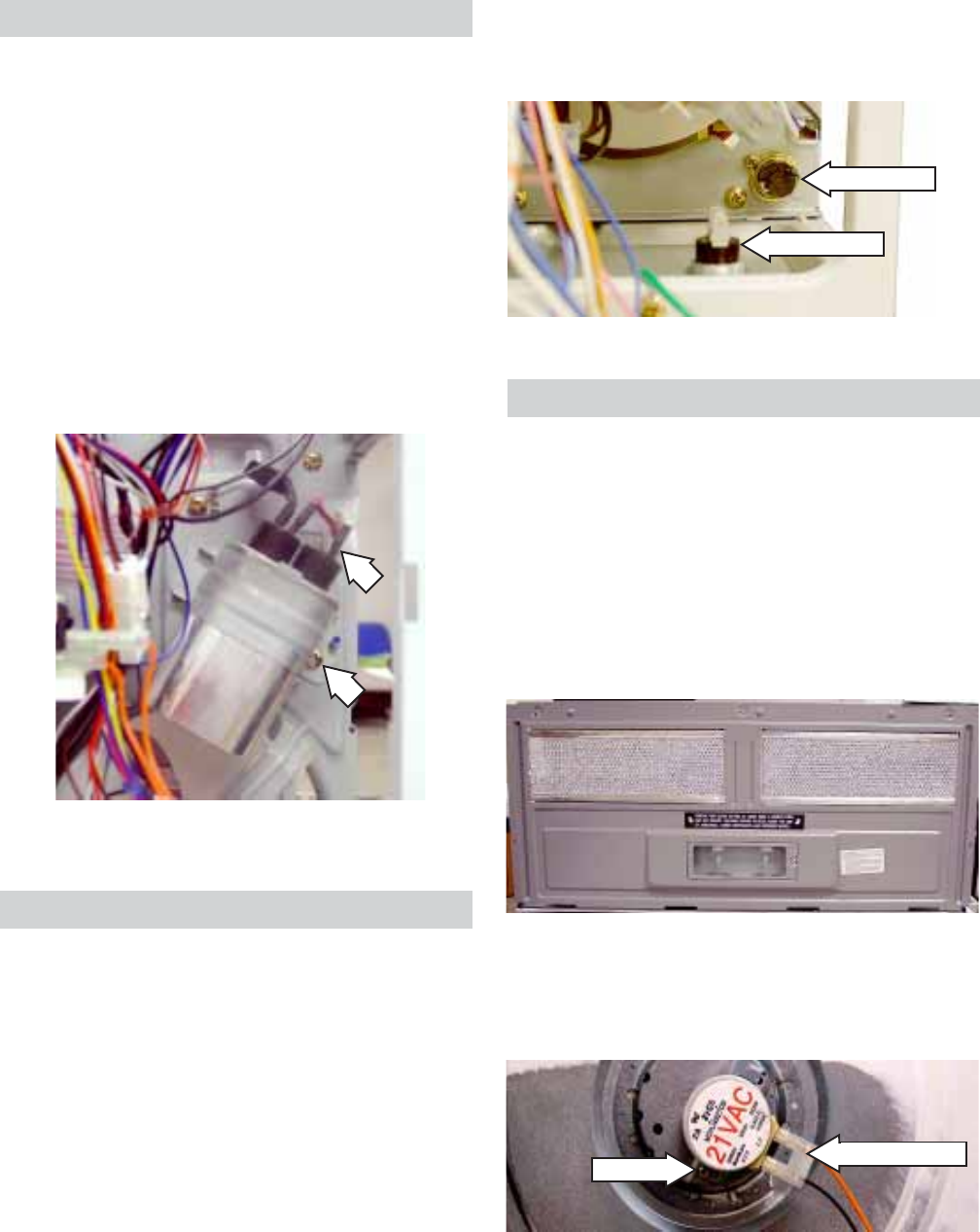
Cooling Fan and Motor
Resistance through the cooling fan motor from
the power cord (L) to CN04 pin 7 is approximately
24.7 ohms. The door (primary interlock) must be
closed to complete circuit.
The cooling fan motor, in series with the drive
motors, provides voltage reduction to 21 VAC.
Removal
Remove the microwave (see Microwave Removal
and Component Access). Remove the screw at the
top of the control panel.
Slide the control panel up and remove it.
Disconnect 8 electrical connectors and the
ground wire from the control panel.
Move the TCO out of the way. Disconnect the
power transformer.
Remove 3 screws from the fan motor mounting
plate. Slide the mounting plate forward to allow
access to the fan blade. Slide the fan blade off of
the fan motor shaft.
Remove 2 screws from the fan motor.
Remove the fan motor from the fan mounting
plate and remove the 2 wires.
– 13 –
Magnetron Thermal Cutout (TCO)
The magnetron TCO is located on the magnetron
and shuts off when the magnetron temperature
reaches 150°F (65.5°C).
The magnetron TCO is a normally closed switch.
An open reading across the TCO indicates a
failed TCO. The magnetron TCO is resetable
Removal
Remove the microwave (see Microwave Removal
and Component Access). Disconnect the 2 wires
and remove the screws from the magnetron TCO
.
Cavity Thermal Cutout (TCO)
The cavity TCO is located on the top of the
microwave oven on the left side of the forward
vent duct. The microwave oven shuts off when
the temperature of the cavityTCO reaches 212°F
(100°C).
The cavity TCO is a normally closed switch. An
open reading across the TCO indicates an
overtemperature condition or failed TCO. The
cavity TCO is not resettable.
Removal
Remove the microwave (see Microwave Removal
and Component Access).
Slide the cavity TCO from the two tabs and
remove the 2 connectors.
Cavity TCO
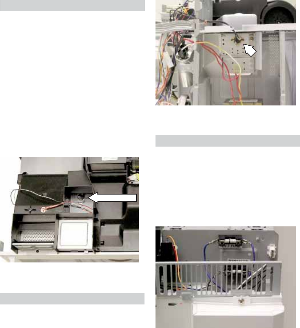
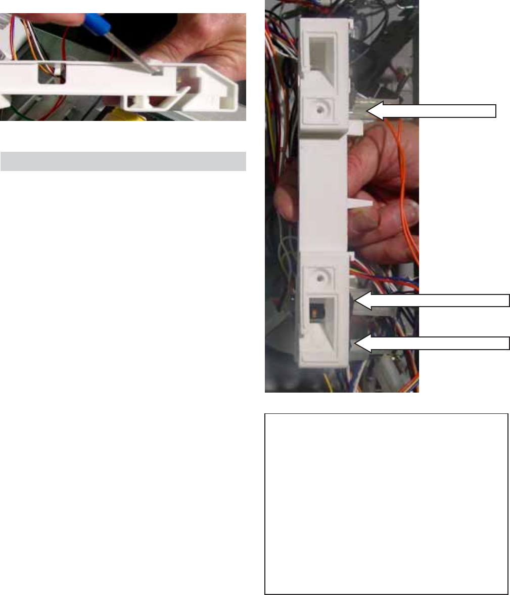
Fuses
The main and high voltage transformer fuses are
located behind the hidden vent, above the control
panel.
Removal
Remove the hidden vent (see Microwave Removal
and Component Access).
Remove the grille to access the fuses.
– 14 –
Gas Sensor
The gas sensor detects humidity changes during
sensor cook functions and transmits this
information to the main board.
The gas sensor is located in the air exhaust duct,
behind the grille on the left side.
To check, run diagnostics (see Diagnostics Test).
Removal
Remove the hidden vent (see Microwave Removal
and Component Access). Slide white plastic
retainer forward and pull the gas sensor down.
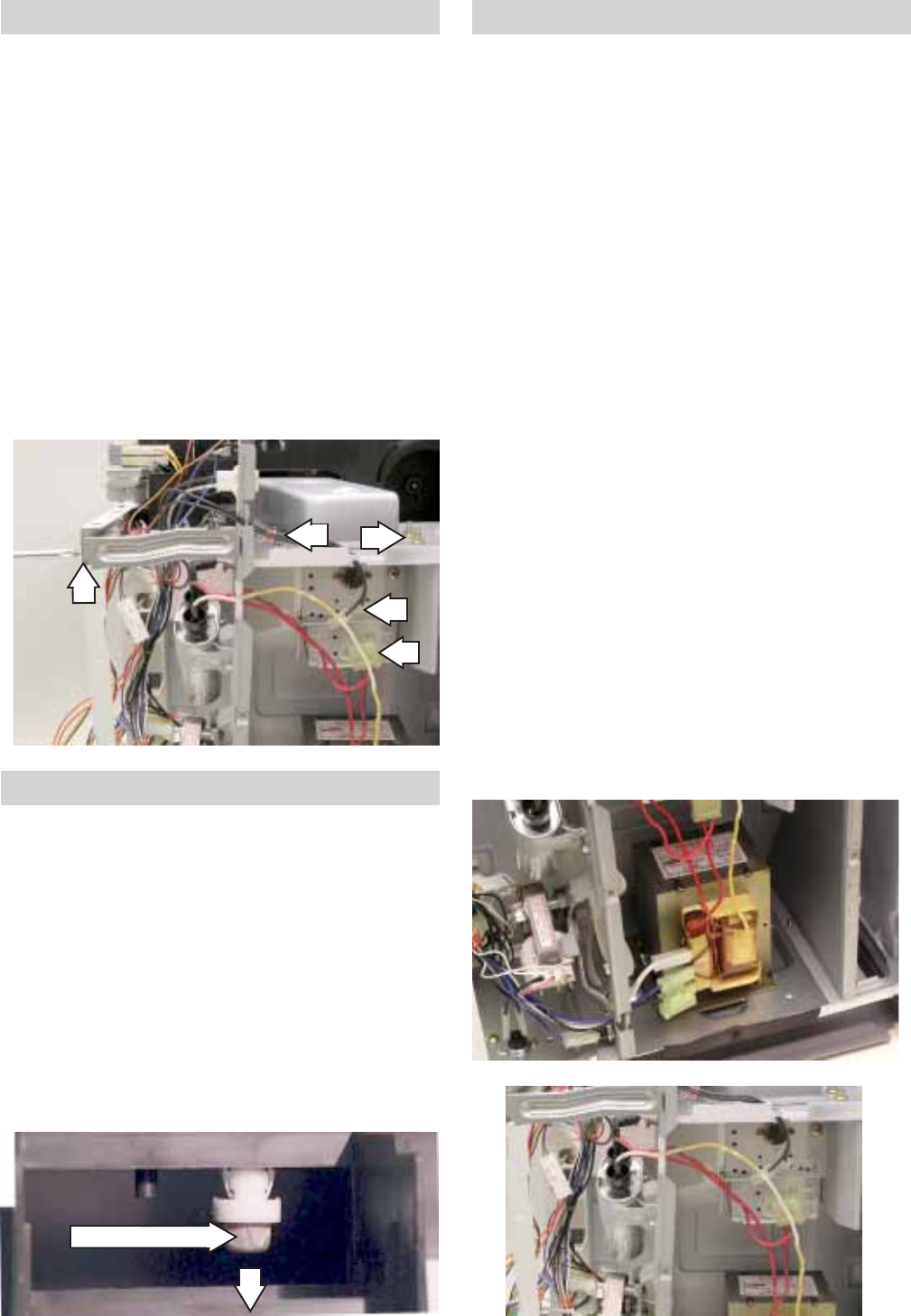
Transformer
The transformer is located behind the fan
mounting plate below the magnetron.
Resistance through the transformer from the
power cord (L) to the high-power secondary
interlock (blue wire) is approximately 0.32 ohms.
The door (primary and monitor interlock) must be
closed.
Resistance through the transformer from the
high-power secondary interlock (blue wire) to the
low-power secondary interlock (single white wire)
is approximately 28.7 ohms. The door (monitor
interlock) must be closed.
Removal
WARNING: Prior to servicing the transformer, be
certain the capacitor is discharged. Manually
discharge by placing an insulated-handle
screwdriver between the diode connection of the
capacitor and the oven chassis ground.
Remove the microwave (see Microwave Removal
and Component Access). Remove the screws and
the bottom panel. Disconnect electrical
connectors. Remove the white and red wires
from the capacitor and the red wires from the
magnetron.
Caution: The transformer is heavy.
Remove 4 screws from the bottom that hold the
transformer in place.
Magnetron
The magnetron is located behind the fan mounting
plate.
Removal
WARNING: Prior to servicing the magnetron, be
certain the capacitor is discharged. Manually
discharge by placing an insulated-handle
screwdriver between the diode connection of the
capacitor and the oven chassis ground.
Remove the microwave (see Microwave Removal
and Component Access). Remove the TCO and
the magnetron electrical connectors. Remove 4
nuts from the top of the magnetron and remove
the screw and brace. Remove the magnetron.
Gas Sensor
– 15 –
Interior Light
Resistance through the interior light from the
CN02 pin 7 to the power cord (L) is approximately
24.9 ohms.
Removal
Note: This component may be able to be
accessed without removing the microwave. If the
2 end screws on top of the outer cover are
accessible, the hidden vent can be removed
without removing the microwave from its
installation.
Remove the hidden vent (see Microwave Removal
and Component Access). Press the tab with a
small screwdriver and lift the interior light cover up
and out.
Hidden Vent Motor
The hidden vent motor is located behind the
hidden vent on the right side.
Resistance through the hidden vent motor from
the CN03 pin 1 to the power cord (N) is
approximately 28.8 ohms.
Removal
Note: This component may be able to be
accessed without removing the microwave. If the
2 end screws on top of the outer cover are
accessible, the hidden vent can be removed
without removing the microwave from its
installation.
Remove the hidden vent (see Microwave Removal
and Component Access). Remove 2 screws and
the motor.
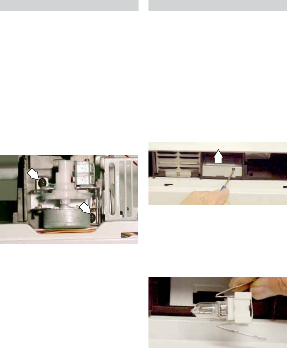
Squeeze the 2 tabs of the light socket and remove
the light assembly.
Note: When installing a new halogen bulb, be
sure to handle the bulb with a clean, dry cloth.
Replace the halogen lamp with a 120VAC, 20W
GE halogen lamp bulb (WB36X10213).

– 16 –
Control Panel
The control panel contains the smart board, the
touchscreen panel, and a three-button circuit
board. Run the test for the control panel (see
Control Performance Test). The control panel is
replaced as an assembly.
Removal
Remove the hidden vent (see Microwave Removal
and Component Access). Remove the grille. Lift up
on the control panel and remove.
Disconnect 8 electrical connectors and the
ground wire from the control panel.
Door Interlock Switches
The oven has 3 interlock switches. All switches
are removed the same.
Door Sensing and Primary Interlock Switches
The primary interlock and monitor switches are
located on the bottom of the plastic switch
bracket. The power relay is mounted on the smart
board. They are activated by the latch heads on
the door. When the door is opened, the switches
interrupt the circuit to all components, except the
oven lamp. A cook cycle cannot take place until
the door is firmly closed, thereby activating both
interlock switches. The primary interlock system
consists of the door sensing switch, primary
interlock switch, and power relay.
Monitor Switch
The monitor switch is operated indirectly by the
bottom latch pawl. The pawl operates a cam
switch, which in turn, activates the monitor
switch. The switch is intended to render the oven
inoperative by means of blowing the monitor fuse
when the contacts of the primary interlock switch
and power relay fail to open when door is opened.
Functions
When the door is opened, the monitor switch
contact closes. At this time, the primary interlock
switch and power relay are in the closed position.
As the door goes to a closed position, the monitor
switch contacts are first opened and then the door
sensing switch and the primary interlock switch
contacts close.The oven has 3 interlock switches.
All switches are removed the same.
Removal
Remove the hidden vent (see Microwave Removal
and Component Access). Remove the grill. Lift up
the control panel and remove.
Remove the 2 T20 Torx screws from the front of
the frame and remove the door switch bracket.
– 17 –
Primary Interlock System Test
WARNING: Disconnect the oven from the power
supply.
Door Sensing Switch
Isolate the switch and connect the ohmmeter to
the common (COM.) and normally open (NO)
terminal of the switch. The meter should indicate
an open circuit with the door open and a closed
circuit with the door closed.
Power Relay
Disconnect 2 wires from the tab terminals on the
circuit board provided in the control panel
assembly. The tab terminals are located in the
area of the circuit board on the component side,
and are connected to the contacts of the power
relay. Check the state of the relay contacts using
an ohmmeter. The relay contacts should be open.
If the relay contacts are closed, replace the circuit
board.
Primary Interlock Switch Test
Isolate the switch and connect the ohmmeter to
the common (COM.) and normally open (NO)
terminal of the switch. The meter should indicate
an open circuit with the door open and a closed
circuit with the door closed. If improper operation
is indicated, replace the primary interlock switch.
Note: The primary interlock switches are not
adjustable and must be replaced if test is failed.
Door Sensing Switch:
• Door Closed - 0 ohms
• Door Open - Infinite ohms
Monitor Interlock Switch:
• Door Closed - Infinite ohms
• Door Open - 0 ohms
Primary Interlock Switch:
• Door Closed - 0 ohms
• Door Open - Infinite ohms
Interlocks (Door Latch Switches)
Interlocks are designed as follows:
Door Sensing Switch (top)
Monitor Interlock Switch (middle)
Primary Interlock Switch (bottom)
Note: Remove the wires from the switches
before checking continuity.
Using a small screwdriver, release the tab and
remove the door interlock switch from the door
switch bracket. Disconnect the electrical
connector.
– 18 –
High Voltage Capacitor
Removal and Replacement
WARNING: Prior to servicing, be certain the
capacitor is discharged. Manually discharge by
placing an insulated-handle screwdriver between
the diode connection of the capacitor and the
oven chassis ground.
Remove the hidden vent (see Microwave Removal
and Component Access). Remove the screw and
grill. Lift the control panel up and remove.
Remove the screw from the capacitor brace.
Disconnect 3 wires from the capacitor. Remove
the capacitor and brace from the oven.
Remove the capacitor from the capacitor brace.
Bottom and Hood Thermal Cutout (TCO)
The bottom TCO will interrupt the operation of the
oven when it reaches 248°F (120°C).
The hood TCO is a normally open switch. When it
reaches 158°F (70°C), the vent motor turns on.
Removal procedures are the same for both TCOs.
Removal and Replacement
Remove the hidden vent (see Microwave Removal
and Component Access). Remove the screw and
the grill (see Hidden Vent Motor). Lift the control
panel up and remove.
Turntable Motor
Resistance through the turntable motor from the
CN02 pin 4 to the power cord (L) is approximately
158.5 ohms. The door (primary and monitor
interlock) must be closed.
Removal
Remove 5 screws from the bottom of the
microwave oven cabinet and remove the bottom
plate.
Remove the screw, then rotate the motor CCW 1/
8 turn. Remove the turntable motor. Disconnect 2
wires from the motor.
Disconnect
Screw
Remove 2 wires from the TCO. Remove the
screw that holds the TCO in place and slide the
tab of the TCO out of the oven frame.
Bottom TCO
Hood TCO
– 19 –
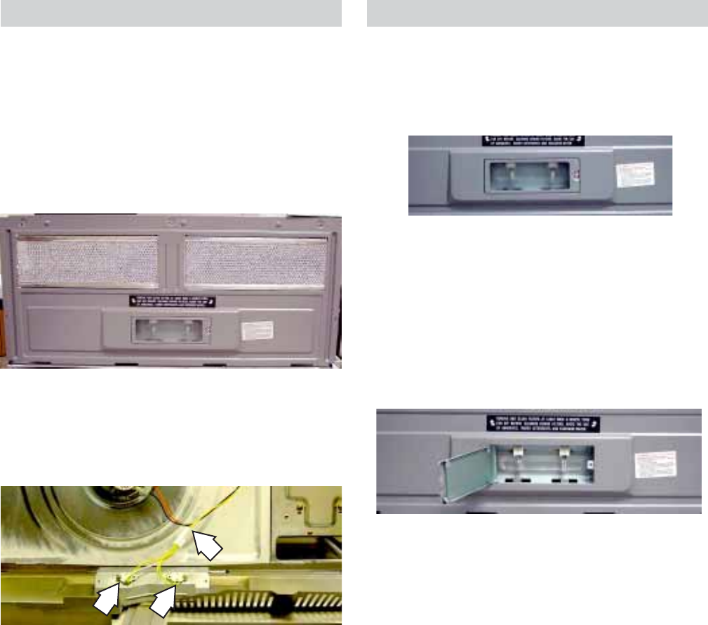
Surface Lamps
Removal
Remove the screw on the surface lens panel and
open the panel.
Surface Lamp Assemblies
Resistance through the surface lamps from the
CN04 pin 3 to the power cord (N) is approximately
62 ohms.
Removal
Remove 5 screws from the bottom of the
microwave oven cabinet and remove the bottom
plate.
Remove the screw from each lamp socket and
remove the lamp assembly from the oven.
Disconnect the electrical connector.
Pull the light out of the socket.
Note: When installing a new halogen bulb, be
sure to handle the bulb with a clean, dry cloth.
Replace the halogen lamp with a 120VAC, 20W
GE halogen lamp bulb (WB36X10213).
– 20 –
Control Performance Test
Set Time:
1. Touch OPTIONS on the HOME display.
2. Touch SET CLOCK on the OPTIONS display.
3. Using the numbers on the touchscreen, enter
the time of day. Press ENTER when finished
or CLEAR to erase the time you entered.
4. Select AM or PM from the touchscreen. Press
ENTER when finished or BACK to enter a new
time.
• Alternately touch each function pad and
enter time, temperature, and power level
selection for the function.
• Touch CLEAR after each function test to
clear that function.
• Repeat the procedure for each function to
exercise each pad.
• Control and display should respond to
each entry.
• Display should revert to Time-Of-Day after
each CLEAR.
Troubleshooting
Sensor Test (Quick Test)
Press and hold the OFF and LIGHT buttons for 3
seconds. Note diagnostic number displayed.
15 to 185 = Normal
213 or higher = Sensor failed to open, sensor
unplugged, wiring, or smart board.
Less than 6 = Shorted sensor or smart board.
Caution: Do NOT check the white and orange
sensor leads. Checking could damage sensor.
Note: Black and red heater terminal leads should
read 30 Ω.
– 21 –
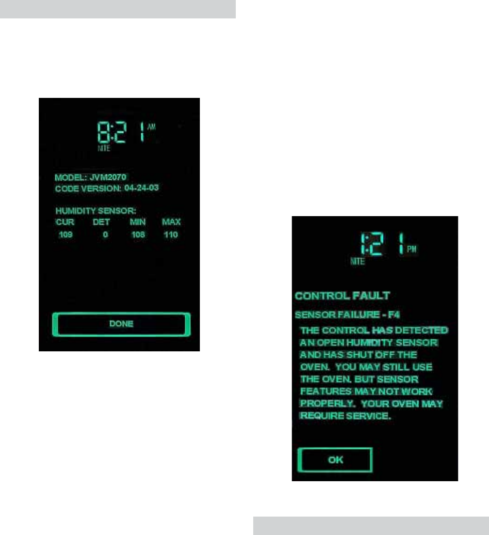
Diagnostics Test
Simultaneously press the LIGHT and OFF keys
for 3 seconds. The diagnostics screen will appear
in the LCD display.
Sample Diagnostics Screen
Displayed Information
• MODEL - Identified at power-up by the keytail
ID option.
• CODE VERSION - The date the code file was
sent to GEA for testing (MM-DD-YY).
• HUMIDITY SENSOR - The CUR (current),
DET (detection point), MIN (minimum), MAX
(maximum) humidity sensor data will update
continuously.
Error Message
F1 Convection - Open thermal sensor
F2 Convection - Shorted thermal sensor
F3 - Keypanel shorted for more than 60 seconds
F4 - Open humidity sensor
F5 - Shorted humidity sensor
F10 - Shorted touch panel
Note: Any “F” code will cause an error sound to
beep for 3 cycles. One cycle will sound 2
seconds on, 1 second off.
Sample “F” Code page
The CUR value is the present A/D value of the
sensor. DET is the value at the moment the
humidity detection point was reached. MIN is the
lowest humidity point measured during entire
feature’s run. MAX is the highest humidity value
measured during the feature’s run. These data
points are the dynamic measurements of the
sensor, not the calculated values.
Pressing the DONE key terminates the diagnostic
screen. The screen returns to the previous or
HOME screen. The diagnostic screen will timeout
and return to the previous screen after receiving
no input for 5 minutes.
Demonstration Mode
In demonstration mode, everything will operate on
the unit except the high voltage section.
To enter the demonstration mode, disconnect the
power for 30 seconds then reapply power.
Simultaneously press the HELP screen pad and
the BOOST button for 3 seconds. The word
DEMO will appear in the LCD display.
To exit the demonstration mode, disconnect the
power for 30 seconds then reapply power.

– 22 –
Performance Test
1. Measure the line voltage (loaded). This test is
based on normal voltage variations of 108V to
132V. Low voltage will lower output power and
temperature rise.
2. Place a beaker (WB64X0073) containing
1 liter of water (1000ml, 59°F - 75°F) on the
turntable and record the starting water
temperature with a thermometer. (Do not use
any other load or dish as results will very from
standard).
3. Set the microwave oven at HIGH power for
2 minutes and 3 seconds.
4. Turn on the oven.
5. Record the water temperature.
The minimum difference between the initial and
ending temperature should be 40°F at 120V.
Microwave Leakage Test
1. Place 275 ml. of water in a 600 ml beaker
(WB64X5010).
2. Place the beaker in the center of the oven
shelf.
3. Set the meter to the 2450 MHz scale.
4. Turn the oven on for 5 minutes.
5. Hold the probe perpendicular to the surface
being tested and scan the surfaces at a rate
of 1 inch/sec.
Test the following areas:
• The entire perimeter of the door and
control panel.
• The viewing surface of the door window.
• The exhaust vents.
6. The maximum leakage is 4 MW/CM2.
7. Record data on the service invoice and
microwave leakage report.
Note: The maximum allowable leakage is 5 MW/
CM2. 4 MW/CM2 is used to allow for measurement
and meter accuracy.
Inform the manufacturer of any oven found to
have emission in excess of 5 MW/CM2. Make
repairs to bring the unit into compliance at no cost
to the owner and try to determine the cause.
Instruct the owner not to use the oven if it has not
been brought into compliance.
High Voltage Capacitor
The high voltage capacitor has an internal shunt
resistor to automatically discharge the capacitor
when the oven turns off. Under normal operation,
the capacitor should fully discharge within 30
seconds.
– 23 –
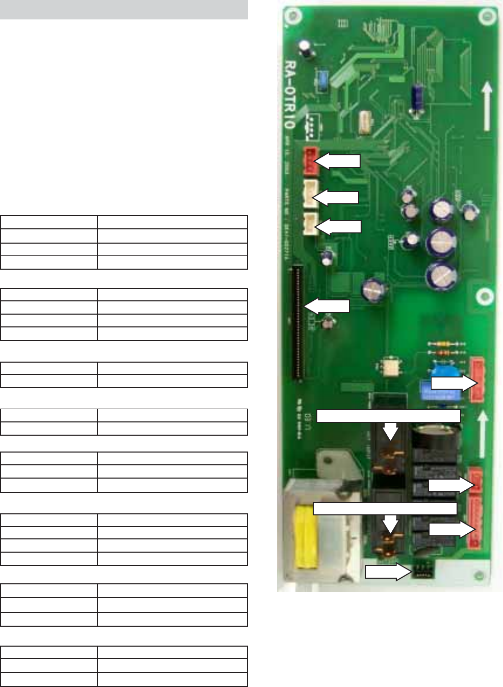
Smart Board
The smart board contains the power relay, LVT,
vent blower triac, surface light relays, and other
components to perform the proper switching
circuits. Several disconnect plugs are also
located on the smart board.
CN01 - Ribbon connector.
Interfaces the smart board and the touch pad.
CN02 - Primary LTV, Main Relay, Inrush Relay,
and Turntable.
Interfaces the smart board and the key module.
CN03
CN05
CN04
CN08
CN06
CN07
CN02
CN01
Low-Power Secondary Interlock
High-Power Secondary Interlock
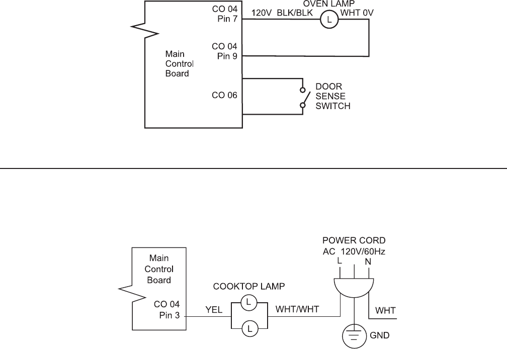
CN04 - Cooktop Lamp Relay Connector
CN03 - Vent Blower Connector
Pin 1 AZU-1
Pin 3 VIL-1
Pin 5 GRA-1
Pin 7 BRN-1
Hood TCO
Main Fuse
Louver Motor
Pin 4 ORG-1
Pin 5 PIN-1
Pin 7 WHT-9
Pin 9 BLK-7
Turntable Motor
Fan Motor
Fan Motor
Oven Lamp
Pin 1 BLU-2
Pin 3 YEL-1 Cooktop Lamps
Cooktop Lamps
CN05
Pin 1 ORG
Pin 2 ORG Door Sense Switch
Door Sense Switch
CN06 - Door Sensing Connector
Pin 1 YEL
Pin 2 BLU
Pin 3 RED
Louver Switch
CN07 - Louver Motor Switches Connector
Pin 1 ORG
Pin 2 WHT
Pin 3 BLK
Pin 4 RED
Gas Sensor
CN08 - Gas Sensing Connector
Louver Switch
Louver Switch
Gas Sensor
Gas Sensor
Gas Sensor
WHT/WHT To High Power Interlock
Low-Power Secondary Interlock
Cooktop Lamps
HV Transformer
To Low Power Interlock
High-Power Secondary Interlock
Power Cord N
HV Transformer Fuse
WHT/WHT
WHT
WHT/WHT
WHT/WHT
WHT
Hood TCO
– 24 –
Strip Circuits
Vent Motor Does Not Work
Fan Motor Does Not Work
Louver Motor Does Not Work
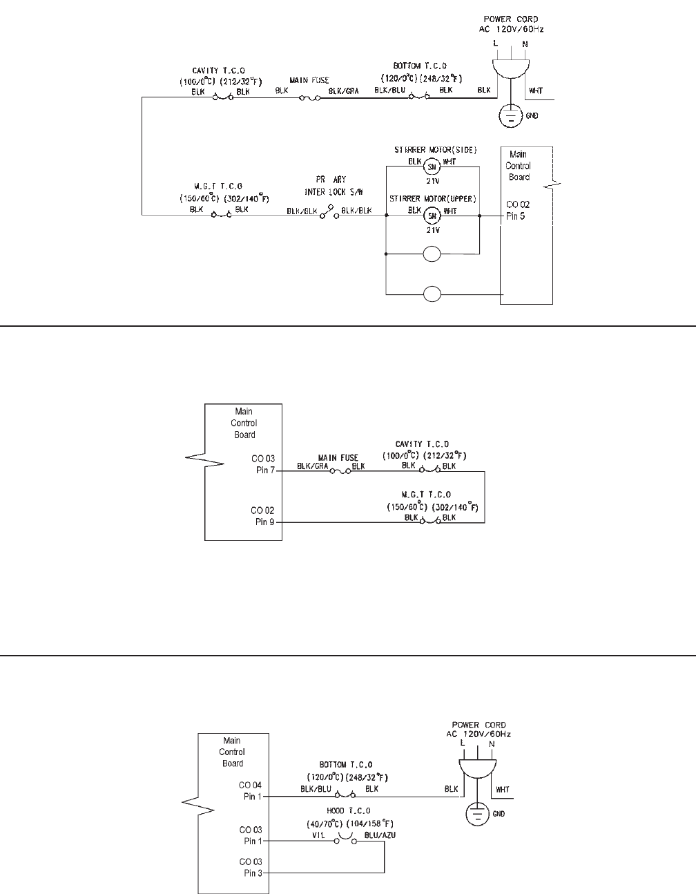
– 25 –
Note: The Magnetron Tube TCO automatically
resets when the conditions return to normal. The
Cavity TCO is not resetable. It must be replaced.
Dead Unit - Cavity or Magnetron TCO Does Not Work
Top Stirrer, Side Stirrer, or Drive Motor Does Not Work
Note: The Bottom TCO is not resetable. It must be
replaced.
Dead Unit - Bottom TCO Does Not Work
FAN MOTOR
DRIVE MOTOR
FM
DM
0V
120V
21V
BLK PIN
BLK ORG
Pin 4
– 26 –
Interior Light Does Not Work
Surface Lamps Do Not Work
– 27 –
Magnetron Does Not Work
1
2
1 - Red
2 - White
3 - Blue
4 - Black
3
4
2
Replace the HV transformer.
Does the magnetron work?
Replace the magnetron.
Replace the primary interlock switch or repair
faulty wiring between the HV transformer and
the primary interlock switch.
Does continuity exist between the HV
transformer black wire and power cord with
primary interlock closed (door closed)? No
Yes
Does continuity exist between the HV
transformer blue wire and secondary interlock-2
blue wire thru HV transformer fuse?
Replace the HV transformer fuse or
repair faulty wiring.
No
Yes
No
Does continuity exist between the secondary
interlock-2 blue wire and power cord? Repair faulty wiring.
No
Yes
Does continuity exist between the HV
transformer white wire to power cord thru
secondary interlock - 1 (door closed) and
monitor interlock switch open (door closed)?
Yes
Repair faulty wiring.
No
Replace the main control board.
Does the magnetron work?
No
Replace the HV capacitor.
Does the magnetron work?
No
– 28 –
Note: For servicing replacement use 16GA. 105°C thermoplastic covered leads or as noted on special leads.
WARNING: Power must be disconnected before servicing this appliance.
Wiring Diagram
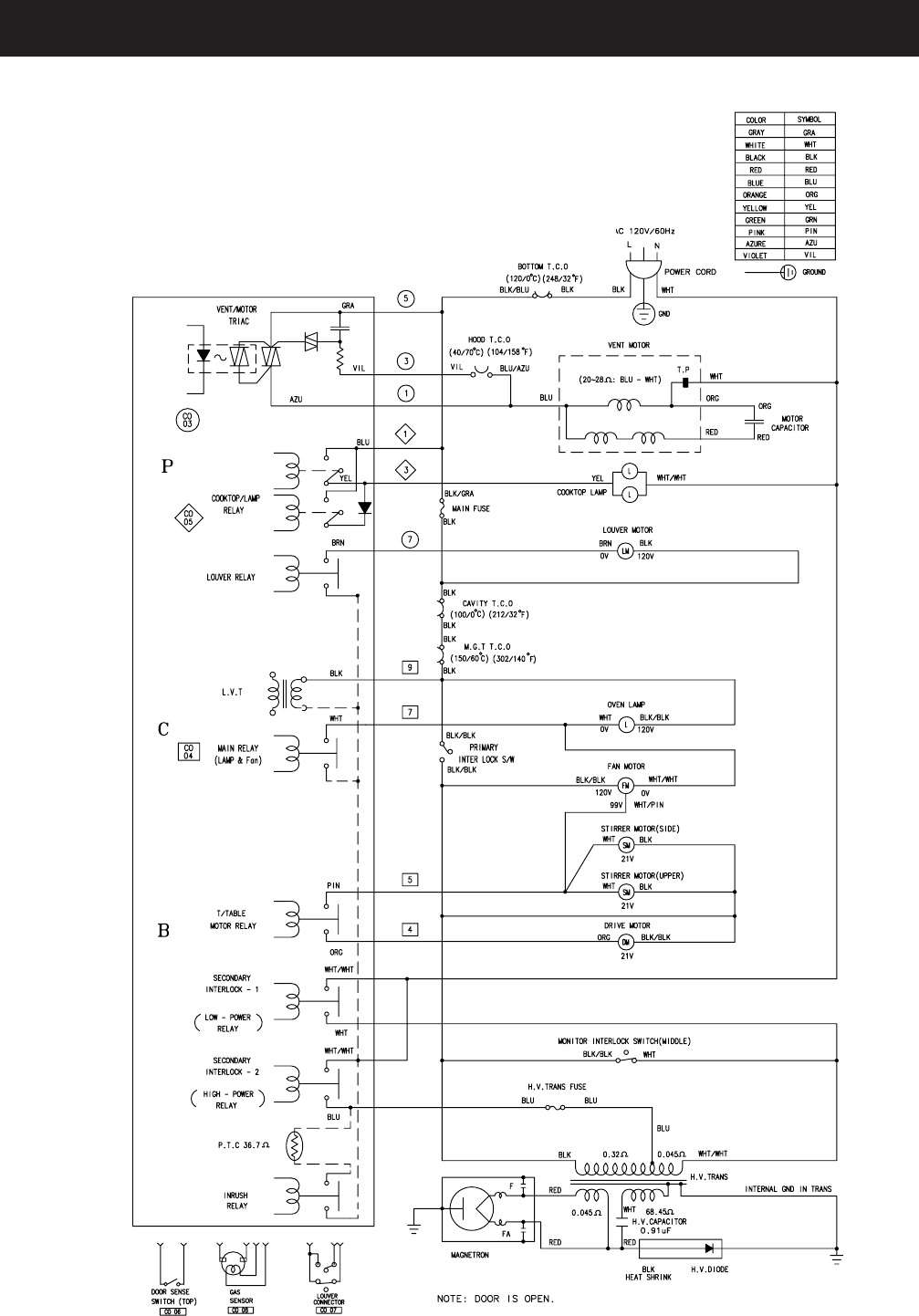
– 29 –
Code No. : DE99-00125F
WARNING: Power must be disconnected before servicing this appliance.
Schematic
– 30 –
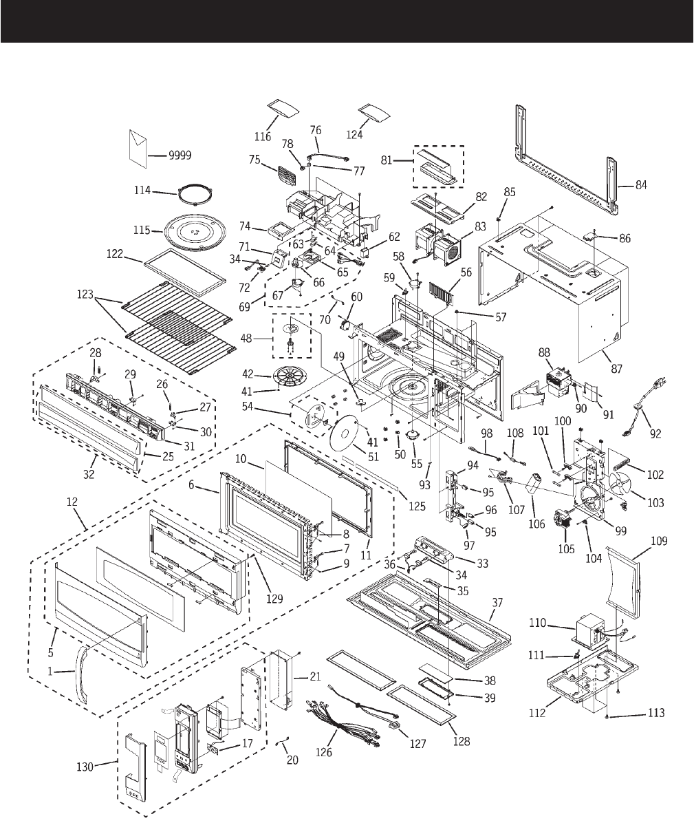
Illustrated Parts Catalog

– 31 –
VIEW NUMBER CATALOG NUMBER DESCRIPTION QUANTITY
1 WB15X10135 HANDLE WH 1
5 WB55X10673 DOOR-A ASM 1
6 WB55X10668 DOOR MAIN ASM 1
7 WB05X10012 DOOR-KEY 2
8 WB05X10006 SPRING-KEY 2
9 WB06X10060 PIN-HINGE 2
10 WB06X10516 FILM-DOOR 1
11 WB55X10669 CHOKE COVER 1
12 WB56X10461 DOOR ASM WH 1
17 WB27X10725 KEY-MODULE 1
20 WB18X10140 WIRE LEAD-F 1
21 WB27X10726 SMART BOARD 1
25 WB07X10730 GRILLE COVER ASM WHT 1
26 WB01X10246 SPRING-LOUVER 1
27 WB02X10970 EARTH-GRILLE "A" 1
28 WB02X10967 HINGE-GRILLE "R" 1
29 WB02X10968 HINGE-GRILLE "M" 1
30 WB02X10969 HINGE-GRILLE "L" 1
31 WB07X10724 GRILLE WH 1
32 WB36X10273 GRILLE ASM WHT 1
33 WB06X10450 BRACKET-BOTTOM LAMP 1
34 WB36X10213 BULB HALOGEN (120V 20W) 2
35 WB06X10517 BRACKET-ENCLOSURE 1
36 WB08X10026 SOCKET LAMP 1
37 WB56X10450 BASE BOTTOM SUB ASM 1
38 WB36X10071 GLASS-COOKTOP LAMP 1
39 WB36X10217 COVER-GLASS 1
41 WB06X10126 BUTTON-LOCK 2
42 WB06X10518 COVER-STIRRER(TOP) 1
48 WB06X10519 STIRRER(TOP) ASM 1
49 WB06X10520 COUPLER-TT 1
50 WB06X10521 HOLDER-RACK 8
51 WB06X10522 COVER-STIRRER(SIDE) 1
54 WB06X10523 STIRRER(SIDE) ASM 1
55 WB26X10136 MOTOR TURNTABLE 1
56 WB06X10524 COVER-FRONT 1
57 WB01X10065 NUT MAGNETRON 4
58 WB26X10037 MOTOR STIRRER 1
59 WB27X10195 TCO CAVITY 1
60 WB26X10137 MOTOR-DRIVE(SIDE) 1
62 WB27X10170 CAPACITOR-MOTOR 1
63 WB24X10070 SWITCH-MICRO 1
64 WB24X10069 SWITCH-MICRO 1
65 WB06X10283 BRACKET-CAM PLATE 1
66 WB38X10057 CAM-LOUVER 1
67 WB26X10112 MOTOR-DRIVE 1
69 WB07X10442 CAM LOUVER ASS'Y 1
70 WB18X10122 WIRE GRND PCB 1
71 WB06X10525 COVER-HALOGEN LAMP 1
72 WB08X10027 SOCKET HAL/LAMP ASM 1
74 WB36X10260 FRAME GLASS HOLDER 1
75 WB02X10955 BKT-BARRIER 1
76 WB18X10241 WIRE HARNESS-S 1
77 WB27X1170 GAS SENSOR 1
78 WB06X0549 HOLDER-SENSOR 1

– 32 –
VIEW NUMBER CATALOG NUMBER DESCRIPTION QUANTITY
81 WB06X10436 HOOD DAMPER ASM 1
82 WB06X10165 BRACKET-V/T MOTOR 1
83 WB26X10138 MOTOR-VENTILATION 1
84 WB56X10446 PLATE MOUNTING ASM 1
85 WB01X10071 NUT TOP MOUNTING 1
86 WB06X10122 BRACKET-POWER CORD 1
87 WB56X10462 CASE OUTER WH 1
88 WB27X10735 MAGNETRON ASM 1
90 WB27X10166 TCO - MAGNETRON 1
91 WB06X10526 BRACKET-MGT 1
92 WB18X10200 POWER CORD ASM 1
93 WB01X10119 SCREW-TAPPING 2
94 WB06X10289 LATCH-BODY 1
95 WB24X0829 SWITCH-MICRO 2
96 WB24X0830 SWITCH-MICRO 1
97 WB06X10128 LEVER-SWITCH LOWER 1
98 WB18X10055 WIRE HARNESS-B 1
99 WB06X10527 COVER MOTOR SUB ASM 1
100 WB06X10463 FUSE-HOLDER 2
101 WB27X10474 FUSE 2
102 WB06X10528 SUPPORTER-CAVITY 1
103 WB26X10090 BLADE-FAN 1
104 WB27X10194 TCO HOOD 1
105 WB26X10089 MOTOR-FAN 1
106 WB27X10011 CAPACITOR 1
107 WB06X10287 BRACKET-HVC 1
108 WB27X1160 H.V. DIODE 1
109 WB26X10139 DUCT REAR ASM 1
110 WB27X10724 TRANS-H.V 1
111 WB27X1127 TCO -BOTTOM 1
112 WB56X10448 BASE-PLATE 1
113 WB01X10084 SCREW-WASHER HVT 4
114 WB06X10529 ROLLER GUIDE RING 1
115 WB49X10063 TRAY-COOKING 1
116 WB01X10181 HARDWARE INSTALLATION 1
122 WB02X10956 CHARCOAL FILTER-OPTIONAL 1
123 WB48X10038 RACK WIRE ASM 2
124 WB01X10183 HARDWARE BAG 1
125 49-40335 LABEL-COOKING GUIDE 1
126 WB18X10235 WIRE HARNESS-A 1
127 WB18X10232 WIRE HARNESS-C 1
128 WB06X10288 FILTER GREASE 2
129 WB01X0861 SCREW,DOOR BRKT-BOTTOM 2
130 WB07X10734 CTRL PANEL SUB ASM WHT 1
9999 31-40025 MINI-MANUAL 1
9999 49-40137-1 TEMPLATE-TOP 1
9999 49-40239-1 REAR WALL TEMPLATE 1
9999 49-40329 USE & CARE 1
9999 49-40330 INSTALLATION INSTRUCTION 1

– 33 –
OTR MICROWAVE OVEN WARRANTY
For the period of: GE will replace:
Full one-year Entire oven
Warranty
What GE will not cover
• Service trips to your home to teach you how to use the product.
• Replacement of home fuses or resetting of circuit breakers.
• Incidental or consequential damage caused by possible defects with this appliance.
• Damage to the product caused by accident, fire, floods, or acts of God.
• Failure of the product if it is used for other than its intended purpose or used commercially.
• Improper installation.
This warranty is extended to the original purchaser and any succeeding owner for products purchased
for home use within the USA. In Alaska, the warranty excludes the cost of shipping or service calls to
your home.
Some states do not allow the exclusion or limitation of incidental or consequential damages, so the
above limitation or exclusion may not apply to you. This warranty gives you specific legal rights, and
you may also have other rights which vary from state to state.
To know what your legal rights are in your state, consult your local or state consumer affairs office or
your state’s Attorney General.
Warrantor: General Electric Company, Louisville, KY 40225
From the date of the
original purchase
Any part of the oven which fails due to a defect in materials or
workmanship. During this full one-year warranty, GE will also provide,
free of charge, all labor and in-home service to replace the defective part.
Limited ten-year Magnetron tube
From the second
through the tenth year
from the date of the
original purchase
The magnetron tube, if the magnetron tube fails due to a defect in
materials or workmanship. During the additional limited nine-year
warranty, you will be responsible for any labor or in-home service costs.
