Ge Appliances General Electric Noise Reduction Machine Gfk 0787B Users Manual Genius Modular Redundancy Flexible Triple Redundant (TMR) System User’s Manual,
GFK-0787B to the manual 4c56883e-0616-44ee-aebc-102a4e446445
2015-01-23
: Ge-Appliances Ge-Appliances-General-Electric-Noise-Reduction-Machine-Gfk-0787B-Users-Manual-256149 ge-appliances-general-electric-noise-reduction-machine-gfk-0787b-users-manual-256149 ge-appliances pdf
Open the PDF directly: View PDF ![]() .
.
Page Count: 209 [warning: Documents this large are best viewed by clicking the View PDF Link!]
- Chapter 1 Introduction
- Chapter 2 Input Subsystem
- Chapter 3 Output Subsystem
- Chapter 4 PLC Subsystem
- Chapter 5 Diagnostics
- Chapter 6 Configuration
- Configuration Overview
- Using the GMR Configuration Software
- Getting Started
- GMR Configuration Summary
- Creating/Selecting a File
- Starting a New Configuration
- CPU Configuration
- Adding Bus Controllers and I/O Modules
- Genius Bus Controller Group Configuration
- Configuring the Input Subsystem for a Bus Controller Group
- Configuring the Output Subsystem for a Bus Controller Group
- Configuring the Non-Voted Discrete I/O for a Bus Controller Group
- Configuring the Non-Voted Analog I/O for a Bus Controller Group
- Creating the G_M_R10 Output File
- Printing the GMR Configuration
- Completing the Logicmaster 90 Configuration
- Configuring Genius I/O Blocks
- Chapter 7 Programming Information
- Programming Overview
- Program Instruction Set for GMR
- Estimating Memory Usage
- Estimating Bus Scan Time
- Reserved References
- Input and Output Addressing for GMR
- Register (%R) Memory Assignment for GMR
- System Status (%S) References
- GMR Status and Control (%M) References
- Programming for Startup
- I/O Point Faults
- Programming for I/O Shutdown
- Programming for Fault and Alarm Contacts
- Reading GMR Diagnostics
- Programming for Global Data
- Adding the GMR System Software to a New Application Program Folder
- Adding the GMR Configuration to the Application Program Folder
- Storing a Program to the PLC
- Chapter 8 Installation Information
- Genius Bus Connections
- Termination Boards
- Input Wiring
- Single Sensor to Three Blocks (Triple Bus)
- Three Sensors to Three Blocks (Triple Bus)
- Block Wiring for 16-Circuit Source Block in an Input Group
- Block Wiring for 16-Circuit Sink Block in an Input Group
- Block Wiring for 32-Circuit Source Block in an Input Group
- Block Wiring for 32-Circuit Sink Block in an Input Group
- Output Wiring for a 16-Circuit, 4-Block Group
- Output Wiring for a 32-Circuit, 4-Block Group
- Output Wiring for a 32-Circuit, 4-Block Group
- Output Wiring for a 32-Circuit, 4-Block Group
- Appendix A TÜV Certification
- Appendix B Maintenance Override
- Index

GE Fanuc Automation
Programmable Control Products
Genius Modular Redundancy
Flexible Triple Modular
Redundant (TMR) System
User’s Manual
GFK-0787B March 1995

GFL–002
Warnings, Cautions, and Notes
as Used in this Publication
Warning
Warning notices are used in this publication to emphasize that hazardous voltages, cur-
rents, temperatures, or other conditions that could cause personal injury exist in this
equipment or may be associated with its use.
In situations where inattention could cause either personal injury or damage to equip-
ment, a Warning notice is used.
Caution
Caution notices are used where equipment might be damaged if care is not taken.
Note
Notes merely call attention to information that is especially significant to understanding
and operating the equipment.
This document is based on information available at the time of its publication. While ef-
forts have been made to be accurate, the information contained herein does not purport
to cover all details or variations in hardware or software, nor to provide for every pos-
sible contingency in connection with installation, operation, or maintenance. Features
may be described herein which are not present in all hardware and software systems.
GE Fanuc Automation assumes no obligation of notice to holders of this document with
respect to changes subsequently made.
GE Fanuc Automation makes no representation or warranty, expressed, implied, or stat-
utory with respect to, and assumes no responsibility for the accuracy, completeness, suf-
ficiency, or usefulness of the information contained herein. No warranties of merchant-
ability or fitness for purpose shall apply.
The following are trademarks of GE Fanuc Automation North America, Inc.
Alarm Master
CIMPLICITY
CIMPLICITY 90-ADS
CIMPLICITY PowerTRAC
CIMSTAR
GEnet
Genius
Genius PowerTRAC
GMR
Field Control
Helpmate
Logicmaster
Modelmaster
ProLoop
PROMACRO
Series One
Series Three
Series Five
Series Six
Series 90
VuMaster
Workmaster
Copyright 1995 GE Fanuc Automation North America, Inc.
All Rights Reserved

iii
GFK–0787B
Preface
This manual is a reference to planning, configuring and programming a Series 90 -70 PLC
system that utilizes Genius Modular Redundancy (GMR).
The information in this manual is intended to supplement the basic system installation,
programming, and configuration instructions located in the manuals listed on the next page.
Content of this Manual
Chapter 1. Introduction: describes the concept of GMR, and gives an overview of
system components, configuration, and programming.
Chapter 2. Input Subsystem: provides information about the inputs to a GMR system.
Chapter 3. Output Subsystem: describes GMR output groups, output handling, manual
output controls, and load sharing.
Chapter 4. PLC Operation: describes system startup, the CPU sweep in a GMR system,
PLC operation, I/O processing, and communications between redundant PLCs
Chapter 5. Diagnostics: chapter 5 describes the various types of diagnostics available in
a GMR system.
Chapter 6. Configuration: describes configuration for a Series 90-70/Genius GMR system.
Chapter 7. Programming Information: describes the application program interface to
the GMR software.
Chapter 8. Installation Information: provides supplementary installation information
for GMR.
Appendix A. TÜV Certification: describes restrictions placed on the design,
configuration, installation and use of a GMR system that will be applied in an
Emergency Shut Down (ESD) application, for which for a TÜV site application approval
will be sought.
Appendix B. Maintenance Override: The information in this appendix is reprinted by
permission of TÜV. Suggestions are made about the use of maintenance override of
safety relevant sensors and actuators. Ways are shown to overcome the safety problems
and the inconvenience of hardwired solutions. A checklist is given.
Changes for this Version of the Manual
This manual describes a group of features and product enhancements that are
collectively referred to as “GMR Phase II”:
Programming can now be done online. This capability is intended for use during
debug and commissioning.
32-circuit DC Genius I/O blocks can now be used in ”H-pattern” output subsystems.

Preface
iv Genius Modular Redundancy Flexible Triple Modular Redundant (TMR) System
User’s Manual – March 1995
GFK–0787B
The GMR configuration software now allows selection of memory addresses for
external write access. Serial and network communication ports are restricted; the
Genius bus is not. A GMR Genius bus must not be used for communications.
Input autotest is enhanced. External isolation diodes are required.
The method used for input voting adaptation can now be configured to suit the
application.
New diagnostics including parity checks and checksums are provided.
Fault text displayed by the Logicmaster software is improved.
Related Publications
For more information, refer to these publications:
Genius I/O System User’s Manual (GEK-90486-1). Reference manual for system
designers, programmers, and others involved in integrating Genius I/O products in a
PLC or host computer environment. This book provides a system overview, and
describes the types of systems that can be created using Genius products. Datagrams,
Global Data, and data formats are defined.
Genius Discrete and Analog Blocks User’s Manual (GEK-90486-2). Reference manual for
system designers, operators, maintenance personnel, and others using Genius discrete
and analog I/O blocks. This book contains a detailed description, specifications,
installation instructions, and configuration instructions for all currently–available
discrete and analog blocks.
Series 90 -70 PLC Installation and Operation Manual (GFK-0262). This book describes
the modules of a Series 90–70 PLC system, and explains system setup and operation.
Logicmaster 90 -70 User’s Manual (GFK-0263). Reference manual for system operators
and others using the Logicmaster 90–70 software to program, configure, monitor, or
control a Series 90–70 PLC and/or a remote drop.
Logicmaster 90 Software Reference Manual (GFK-0265). Reference manual which
describes program structure and defines program instructions for the Series 90–70 PLC.
Series 90-70 Bus Controller User’s Manual (GFK–0398). Reference manual for the Bus
Controller, which interfaces a Genius bus to a Series 90-70 PLC. This book describes the
installation and operation of the Bus Controller. It also contains the programming
information needed to interface Genius I/O devices to a Series 90-70 PLC.
We Welcome Your Comments and Suggestions
At GE Fanuc automation, we strive to produce quality technical documentation. After
you have used this manual, please take a few moments to complete and return the
Reader’s Comment Card located on the next page.
Jeanne L. Grimsby
Senior Technical Writer

Contents
v
GFK-0787B Genius Modular Redundancy Flexible Triple Modular Redundant (TMR) System
User’s Manual – March 1995
Chapter 1 Introduction 1-1 . . . . . . . . . . . . . . . . . . . . . . . . . . . . . . . . . . . . . . . . . . . . . . .
Components of a GMR System 1-2 . . . . . . . . . . . . . . . . . . . . . . . . . . . . . . . . . . .
Series 90-70 PLCs 1-3 . . . . . . . . . . . . . . . . . . . . . . . . . . . . . . . . . . . . . . . . . . . . . . .
Busses and Bus Controllers 1-4 . . . . . . . . . . . . . . . . . . . . . . . . . . . . . . . . . . . . . .
Operation Overview 1-5 . . . . . . . . . . . . . . . . . . . . . . . . . . . . . . . . . . . . . . . . . . . .
Genius I/O Blocks 1-8 . . . . . . . . . . . . . . . . . . . . . . . . . . . . . . . . . . . . . . . . . . . . . .
Configuration and Programming 1-10 . . . . . . . . . . . . . . . . . . . . . . . . . . . . . . . . .
Chapter 2 Input Subsystem 2-1 . . . . . . . . . . . . . . . . . . . . . . . . . . . . . . . . . . . . . . . . . . .
Overview 2-2 . . . . . . . . . . . . . . . . . . . . . . . . . . . . . . . . . . . . . . . . . . . . . . . . . . . . .
GMR Input Groups 2-3 . . . . . . . . . . . . . . . . . . . . . . . . . . . . . . . . . . . . . . . . . . . . .
Non-Voted I/O in the Input Subsystem 2-4 . . . . . . . . . . . . . . . . . . . . . . . . . . . .
Discrete Inputs 2-5 . . . . . . . . . . . . . . . . . . . . . . . . . . . . . . . . . . . . . . . . . . . . . . . . .
Analog Inputs 2-9 . . . . . . . . . . . . . . . . . . . . . . . . . . . . . . . . . . . . . . . . . . . . . . . . . .
Chapter 3 Output Subsystem 3-1 . . . . . . . . . . . . . . . . . . . . . . . . . . . . . . . . . . . . . . . . .
Overview 3-2 . . . . . . . . . . . . . . . . . . . . . . . . . . . . . . . . . . . . . . . . . . . . . . . . . . . . .
GMR Output Handling 3-3 . . . . . . . . . . . . . . . . . . . . . . . . . . . . . . . . . . . . . . . . .
Output Fault Reporting 3-5 . . . . . . . . . . . . . . . . . . . . . . . . . . . . . . . . . . . . . . . . .
4-Block Output Groups 3-6 . . . . . . . . . . . . . . . . . . . . . . . . . . . . . . . . . . . . . . . . . .
Manual Output Controls and Diagnostics 3-8 . . . . . . . . . . . . . . . . . . . . . . . . . .
Redundancy Modes for Output Blocks 3-9 . . . . . . . . . . . . . . . . . . . . . . . . . . . .
Chapter 4 PLC Subsystem 4-1 . . . . . . . . . . . . . . . . . . . . . . . . . . . . . . . . . . . . . . . . . . . .
System Startup 4-2 . . . . . . . . . . . . . . . . . . . . . . . . . . . . . . . . . . . . . . . . . . . . . . . . .
CPU Sweep in a GMR System 4-5 . . . . . . . . . . . . . . . . . . . . . . . . . . . . . . . . . . . .
Estimating CPU Sweep Time 4-6 . . . . . . . . . . . . . . . . . . . . . . . . . . . . . . . . . . . .
Input Processing 4-7 . . . . . . . . . . . . . . . . . . . . . . . . . . . . . . . . . . . . . . . . . . . . . . .
Output Processing 4-17 . . . . . . . . . . . . . . . . . . . . . . . . . . . . . . . . . . . . . . . . . . . . . .
I/O Shutdown 4-18 . . . . . . . . . . . . . . . . . . . . . . . . . . . . . . . . . . . . . . . . . . . . . . . . .
Communications Between PLCs 4-22 . . . . . . . . . . . . . . . . . . . . . . . . . . . . . . . . . .
Chapter 5 Diagnostics 5-1 . . . . . . . . . . . . . . . . . . . . . . . . . . . . . . . . . . . . . . . . . . . . . . .
Programming for Diagnostics 5-1 . . . . . . . . . . . . . . . . . . . . . . . . . . . . . . . . . . . .

Contents
vi
GFK-0787B Genius Modular Redundancy Flexible Triple Modular Redundant (TMR) System
User’s Manual – March 1995
Diagnostics in a GMR System 5-2 . . . . . . . . . . . . . . . . . . . . . . . . . . . . . . . . . . . .
Setting Up Blocks to Report Genius Faults 5-3 . . . . . . . . . . . . . . . . . . . . . . . . .
GMR Autotesting 5-4 . . . . . . . . . . . . . . . . . . . . . . . . . . . . . . . . . . . . . . . . . . . . . . .
GMR Discrepancy Reporting 5-11 . . . . . . . . . . . . . . . . . . . . . . . . . . . . . . . . . . . . .
Input Line Fault Detection in a GMR Application 5-14 . . . . . . . . . . . . . . . . . . .
The PLC and I/O Fault Tables in a GMR System 5-15 . . . . . . . . . . . . . . . . . . . . .
Manual Output Controls and Diagnostics 5-23 . . . . . . . . . . . . . . . . . . . . . . . . . .
Fault, No Fault, and Alarm Contacts 5-25 . . . . . . . . . . . . . . . . . . . . . . . . . . . . . .
Chapter 6 Configuration 6-1 . . . . . . . . . . . . . . . . . . . . . . . . . . . . . . . . . . . . . . . . . . . . .
Configuration Overview 6-2 . . . . . . . . . . . . . . . . . . . . . . . . . . . . . . . . . . . . . . . .
Using the GMR Configuration Software 6-4 . . . . . . . . . . . . . . . . . . . . . . . . . . .
Completing the Logicmaster 90 Configuration 6-45 . . . . . . . . . . . . . . . . . . . . . .
Configuring Genius I/O Blocks 6-50 . . . . . . . . . . . . . . . . . . . . . . . . . . . . . . . . . . .
Chapter 7 Programming Information 7-1 . . . . . . . . . . . . . . . . . . . . . . . . . . . . . . . . . .
Programming Overview 7-2 . . . . . . . . . . . . . . . . . . . . . . . . . . . . . . . . . . . . . . . . .
Program Instruction Set for GMR 7-3 . . . . . . . . . . . . . . . . . . . . . . . . . . . . . . . . .
Estimating Memory Usage 7-3 . . . . . . . . . . . . . . . . . . . . . . . . . . . . . . . . . . . . . . .
Estimating Bus Scan Time 7-3 . . . . . . . . . . . . . . . . . . . . . . . . . . . . . . . . . . . . . . .
Reserved References 7-4 . . . . . . . . . . . . . . . . . . . . . . . . . . . . . . . . . . . . . . . . . . . .
Input and Output Addressing for GMR 7-5 . . . . . . . . . . . . . . . . . . . . . . . . . . .
Register (%R) Memory Assignment for GMR 7-9 . . . . . . . . . . . . . . . . . . . . . . .
System Status (%S) References 7-10 . . . . . . . . . . . . . . . . . . . . . . . . . . . . . . . . . . .
GMR Status and Control (%M) References 7-11 . . . . . . . . . . . . . . . . . . . . . . . . .
Programming for Startup 7-15 . . . . . . . . . . . . . . . . . . . . . . . . . . . . . . . . . . . . . . . .
I/O Point Faults 7-20 . . . . . . . . . . . . . . . . . . . . . . . . . . . . . . . . . . . . . . . . . . . . . . . . .
Programming for I/O Shutdown 7-20 . . . . . . . . . . . . . . . . . . . . . . . . . . . . . . . . . .
Programming for Fault and Alarm Contacts 7-21 . . . . . . . . . . . . . . . . . . . . . . .
Reading GMR Diagnostics 7-24 . . . . . . . . . . . . . . . . . . . . . . . . . . . . . . . . . . . . . . .
Programming for Global Data 7-27 . . . . . . . . . . . . . . . . . . . . . . . . . . . . . . . . . . . .
Adding the GMR System Software to a New Application Program Folder 7-28
Adding the GMR Configuration to the Application Program Folder 7-29 . . .
Storing a Program to the PLC 7-31 . . . . . . . . . . . . . . . . . . . . . . . . . . . . . . . . . . .

Contents
vii
GFK-0787B Genius Modular Redundancy Flexible Triple Modular Redundant (TMR) System
User’s Manual – March 1995
Chapter 8 Installation Information 8-1 . . . . . . . . . . . . . . . . . . . . . . . . . . . . . . . . . . . .
Genius Bus Connections 8-2 . . . . . . . . . . . . . . . . . . . . . . . . . . . . . . . . . . . . . . . . .
Termination Boards 8-2 . . . . . . . . . . . . . . . . . . . . . . . . . . . . . . . . . . . . . . . . . . . . .
Input Wiring 8-3 . . . . . . . . . . . . . . . . . . . . . . . . . . . . . . . . . . . . . . . . . . . . . . . . . .
Output Wiring for a 16-Circuit, 4-Block Group 8-10 . . . . . . . . . . . . . . . . . . . . . .
Output Wiring for a 32-Circuit, 4-Block Group 8-14 . . . . . . . . . . . . . . . . . . . . . .
Appendix A TÜV Certification A-1 . . . . . . . . . . . . . . . . . . . . . . . . . . . . . . . . . . . . . . . . . .
Appendix B Maintenance Override B-1 . . . . . . . . . . . . . . . . . . . . . . . . . . . . . . . . . . . . . .
Abstract B-1 . . . . . . . . . . . . . . . . . . . . . . . . . . . . . . . . . . . . . . . . . . . . . . . . . . . . . . . . .
Maintenance Override Procedures B-1 . . . . . . . . . . . . . . . . . . . . . . . . . . . . . . . . . .
Recommendations B-3 . . . . . . . . . . . . . . . . . . . . . . . . . . . . . . . . . . . . . . . . . . . . . . . .
Version History B-3 . . . . . . . . . . . . . . . . . . . . . . . . . . . . . . . . . . . . . . . . . . . . . . . . . . .
1section level 1 1
figure bi level 1
table_big level 1
restart lowapp ARestart oddapp: ARestarts for autonumbers that do not restart in
each chapter. figure bi level 1, reset table_big level 1, reset chap_big level 1, reset1
Lowapp Alwbox restart evenap:A1app_big level 1, resetA figure_ap level 1, reset
table_ap level 1, reset figure level 1, reset Figure 1. table level 1, reset Table 1.
these restarts oddbox reset: 1evenbox reset: 1must be in the header frame of
chapter 1. a:ebx, l 1 resetA a:obx:l 1, resetA a:bigbx level 1 resetA a:ftr level 1 resetA
c:ebx, l 1 reset1 c:obx:l 1, reset1 c:bigbx level 1 reset1 c:ftr level 1 reset1
Reminders for autonumbers that need to be restarted manually (first instance will
always be 4) let_in level 1: A. B. C. letter level 1:A.B.C. num level 1: 1. 2. 3.
num_in level 1: 1. 2. 3. rom_in level 1: I. II. III. roman level 1: I. II. III. steps level 1:
1. 2. 3.
1-1
GFK-0787B
Chapter 1Introduction
Genius Modular Redundancy (GMR ) has been developed by GE Fanuc Automation and Silvertech
Limited of the United Kingdom. Silvertech has many years experience applying GE Fanuc products to
high-integrity safety system applications such as Emergency Shutdown and Fire & Gas Detection in the
petrochemical / oil and gas industries. They have captured this expertise in the GMR system software.
GMR is a high-reliability, high-availability redundancy system that provides a scalable solution for many
types of redundancy applications, including critical TMR (Triple Modular Redundancy) applications.
TÜV has certified GMR for classification to these requirements: triplex Class 5, duplex Class 4 and 5,
and simplex Class 4 according to the DIN V19250/DIN V VDE 081 standards. For use of the GMR
system in a TÜV approved safety critical installation, refer to information in Appendix A.
The GMR system is based on standard, off-the-shelf hardware. It utilizes field-proven Series 90-70
PLC and Genius I/O products. Enhancements have been incorporated into the standard PLC CPU,
bus controller, and several Genius I/O blocks specifically for use in GMR systems. These enhanced
products, together with GMR system software, provide input voting by the PLCs, output voting,
support for both discrete and analog I/O, automatic testing of discrete inputs and outputs, and
extensive fault-monitoring capabilities for the application program.
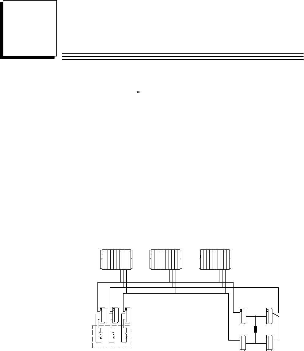
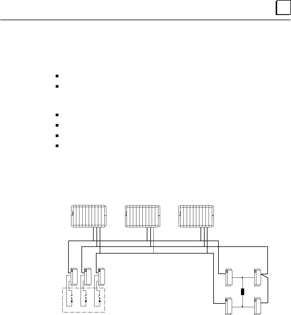
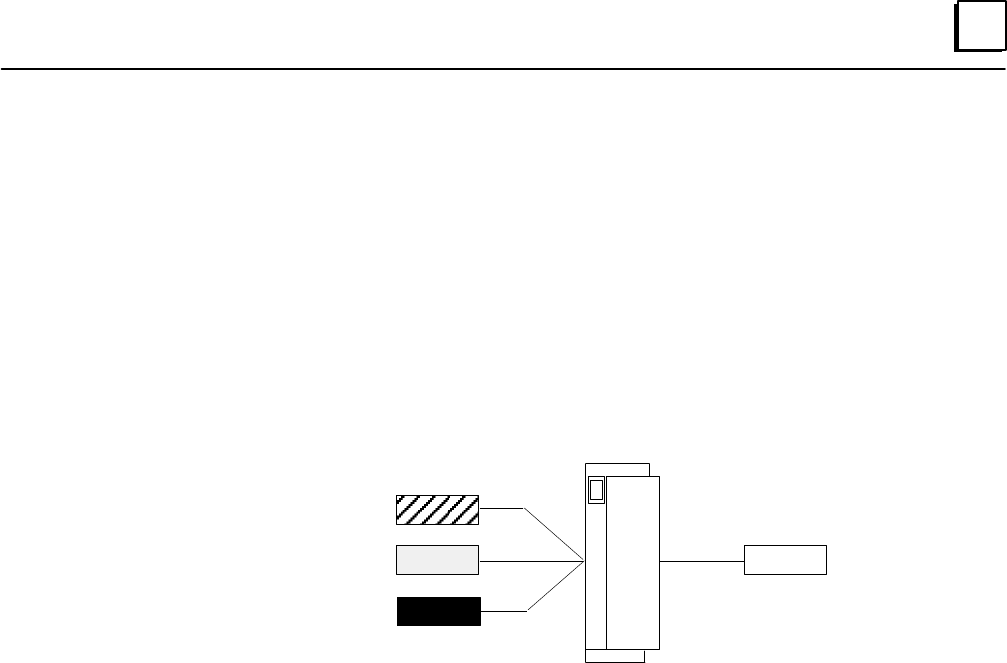
A basic GMR system consists of groups of Genius blocks gathering data from multiple or single
sensors, multiple PLCs running the same application program, and groups of Genius blocks
controlling shared output loads. Communications between the blocks and PLCs and among the
PLCs is provided by the Genius bus.
Triple Input Sensors
Triple Genius Busses
Triple PLCs
Load
GMR provides great configuration flexibility. A system can include 1, 2, or 3 PLCs. There can be just one
I/O subsystem, as represented above, or more than one. Each I/O subsystem can include 1, 2, or 3 busses.
A bus can serve up to a total of 32 devices (I/O blocks, PLCs, and a Hand-held Monitor). The system can
include both non-redundant I/O blocks and individual non-redundant points on redundant blocks.
1
1-2 Genius Modular Redundancy Flexible Triple Modular Redundant (TMR) System
User’s Manual – March 1995 GFK-0787B
Components of a GMR System
GMR Software
GMR software version 2.06 (catalog number IC641SWP714B) provided on diskette
consists of:
Easy-to-use GMR configuration software.
GMR system software, which automatically processes, monitors, and tests redundant I/O.
A download utility for updating programs in systems with SNP multidrop communications.
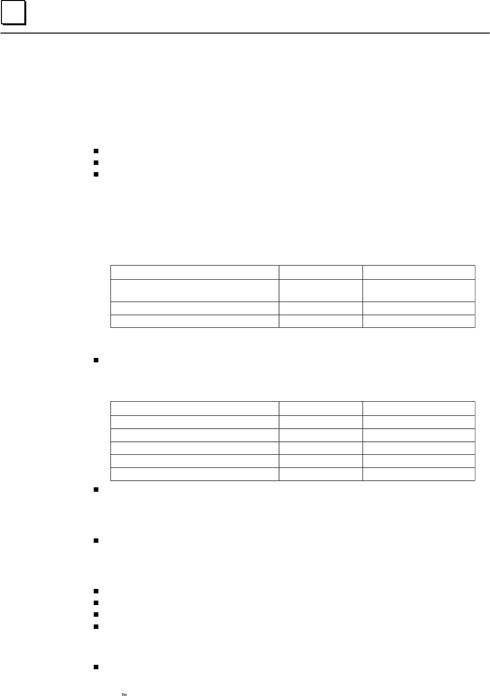
Series 90-70 PLCs
Two models of the Series 90-70 PLC CPU support GMR, CPU 788 and CPU 789. If the
GMR system includes either two or three PLC CPUs, they must be the same model.
Each PLC requires one to three Bus Controllers per bus. Minimum suffixes for GMR
version 2.06 are:
CPUs and Bus Controllers Catalog Number Minimum Suffix
Series 90-70 PLC CPU
IC697CPU788
IC697CPU789
DA
DA
Series 90-70 PLC CPU
IC697CPU788
IC697CPU789
DA
DA
Series 90-70 PLC CPU Memory IC697BEM735 D
Series 90-70 Bus Controller IC697BEM731 N
Genius I/O Blocks
The following standard Genius blocks are supported by the GMR system. These
blocks contain GMR modifications for version 2.06 beginning with the “minimum
suffix” listed:
Block Type Catalog Number Minimum Suffix
24/48 VDC 16-Circuit Source block IC660BBD020 M
24/48 VDC 16-Circuit Sink block IC660BBD021 M
12/24 VDC 32-Circuit Source block IC660BBD024 N
5/12/24 VDC 32-Circuit Sink block IC660BBD025 N
Analog, RTD, and Thermocouple blocks no specific suffix required
Other types of Genius blocks can be used as non-redundant blocks in the same
system.
Additional Items
“SPECIAL SAFETY SYSTEM” red I/O block labels (package of 20 of the same type)
are available: IC660SLA020, A021, A023, A024, A026, A100, A101, A103, A104, A106,
D020, D021, D024, D025. These numbers correspond to the numbers of the blocks.
For example, order label IC660SLA021 for block IC660BBA021.
Logicmaster 90-70 Software: release 4.02 or later.
Hand–held Monitor (optional): IC660HHM501H (version 4.5) or later.
SNP Programming Cable and RS 232/RS 485 adapter. (IC690ACC901)
Multidrop Cable (IC690CBL714) (Two required for connecting 3 CPUs.)
Incompatible Products
Graphics Display System (GDS): GMR is incompatible with Cimplicity 70 GDS.
1
1-3GFK-0787B Chapter 1 Introduction
Series 90-70 PLCs
A GMR system normally consists of one to three identical CPUs running identical
application software. Each CPU is connected to the same input and output subsystems.
Each CPU receives all inputs and performs voting for discrete inputs and mid-value
selection for analog inputs. Each CPU computes the required outputs as a function of the
inputs and the application program logic.
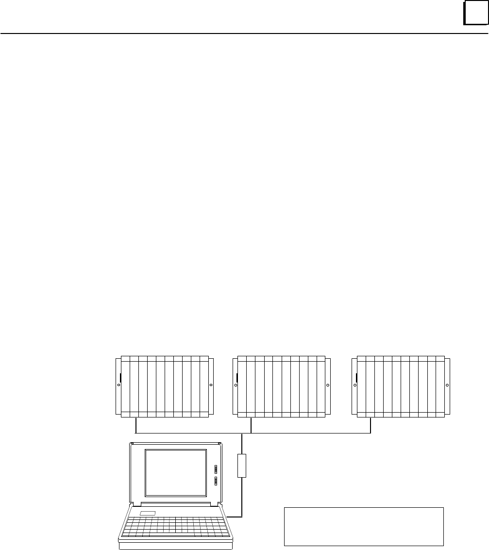
Inter-processor Communications
The PLCs exchange initialization data at startup, then operate asynchronously. They
communicate regularly using Global Data. Each Genius bus scan, each PLC broadcasts up to
64 words of Global Data. This includes 8 words of system information. An additional 56
words of Global Data are available for use by the application program. Redundancy is also
built into Global Data communications. Each message is sent twice, using different busses.
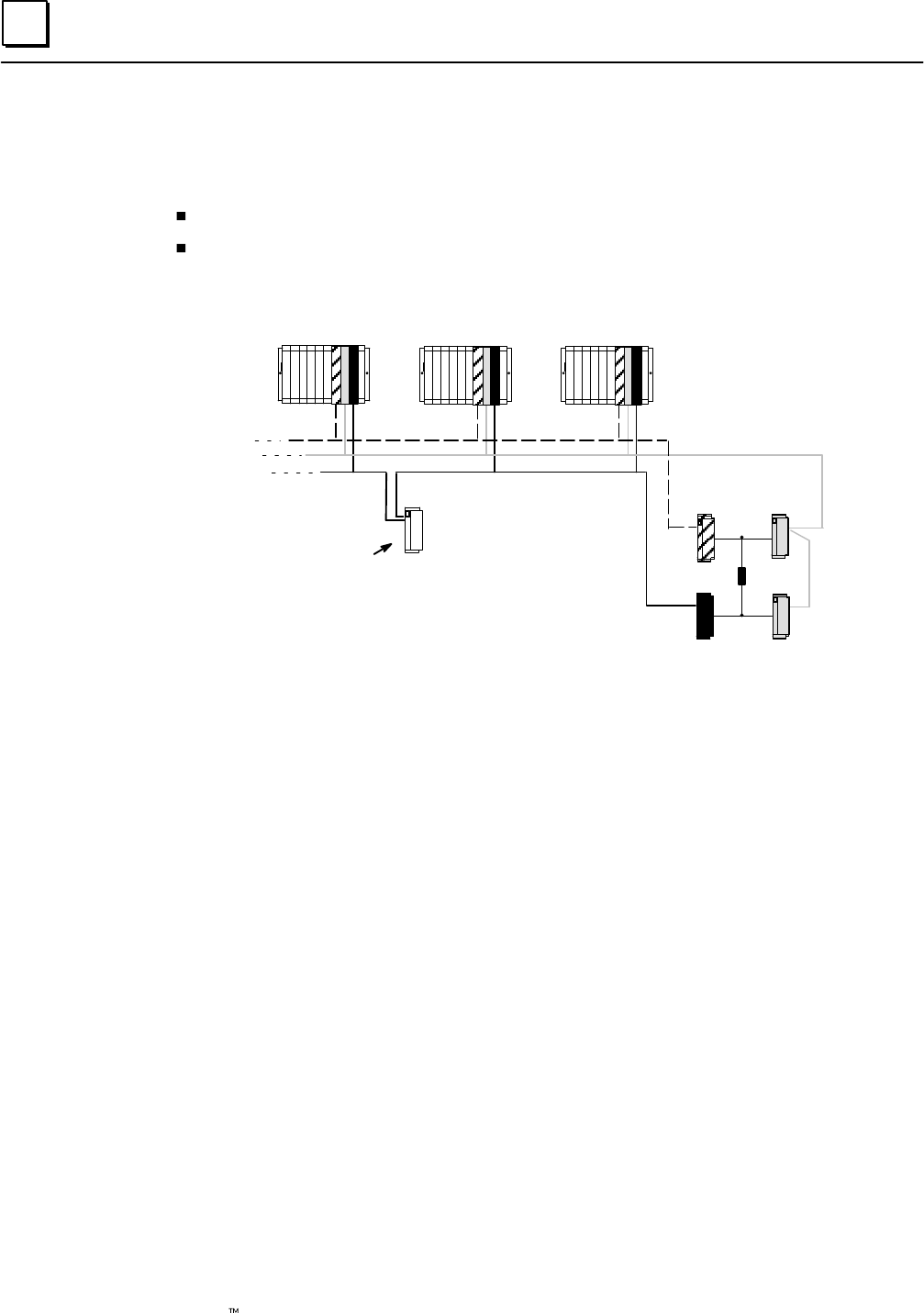
The PLCs may also be joined in a multidrop Series Ninety Protocol (SNP) network. A host
computer on the network can be used for gathering data from the system. In addition, the
SNP network permits convenient program updates using the Logicmaster 90 programming
software and the Program Download utility included on the GMR software diskette.
C
P
U
C
P
U
C
P
U
RS–232/422
Converter
Multidrop Cable
PLC A
Multidrop cable is catalog number
IC690CBL714 (1 cable). Two cables
are needed for 3 CPUs.
PLC CPLC B
All other normal Series 90-70 communications interfaces are also available. If required
for the application, the host software should collect data from each CPU and perform
the necessary voting.
1
1-4 Genius Modular Redundancy Flexible Triple Modular Redundant (TMR) System
User’s Manual – March 1995 GFK-0787B
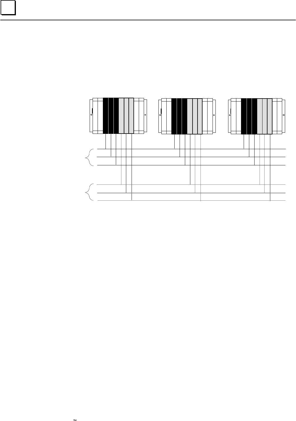
Busses and Bus Controllers
In a GMR system, there can be one to three bus controllers per bus, per PLC. Larger systems
may require more than one I/O subsystem. For example, the GMR system represented below
has two I/O subsystems for a total of six independent Genius busses and 18 bus controllers.
ABCABC ABCABC ABCABC
Bus A
Bus B
Bus C
Bus A
Bus B
Bus C
PLC A PLC CPLC B
I/O Sub–
system
I/O Sub–
system
Each Genius bus uses a single twinax cable over distances of up to 7500 feet and data
rates of up to 153.6K baud.
Each PLC may have up to 31 Genius bus controllers, in multiple racks.
Additional Bus Controllers for Communications
The Genius busses that support GMR input/output groups are also used for internal
communications between PLCs, as explained on the previous page. They should not be
used for datagram communications. Separate busses for communications can be used for
datagrams or additional global data in the application program.
The Bus baud rate should be selected on the basis of the calculations in the Genius I/O
System and Communications User’s Manual (GFK-90486). For correct autotesting in a GMR
system, the Genius bus scan time should not be be more than 60mS.
1
1-5GFK-0787B Chapter 1 Introduction
Operation Overview
Genius Modular Redundancy has been developed for use in systems that have static or nearly
static I/O under normal operating conditions. The system may have:
Normally-on inputs with normally-energized outputs, as in emergency shutdown systems.
Normally-off inputs with normally-deenergized outputs, as in fire and gas detection
systems.
Genius Modular Redundancy provides:
high degree of self-test and monitoring with diagnostics
fault tolerance.
support for centralized or fully distributed systems.
Scalable voting: 2-out-of-3, 2-out-of-2, 1-out-of-2, or simplex.
The example that follows illustrates how the GMR input subsystem, PLC subsystem, and
output subsystem combine to provide a high-availability, high-reliability system.
Input Subsystem Output Subsystem
PLC Subsystem
Load
PLC A PLC CPLC B
1
1-6 Genius Modular Redundancy Flexible Triple Modular Redundant (TMR) System
User’s Manual – March 1995 GFK-0787B
Input Subsystem
In a GMR system, the basic elements of an input subsystem are single or triple sensors
connected to triple Genius blocks. Each block is on a different communications bus
(shown below as A, B, and C).
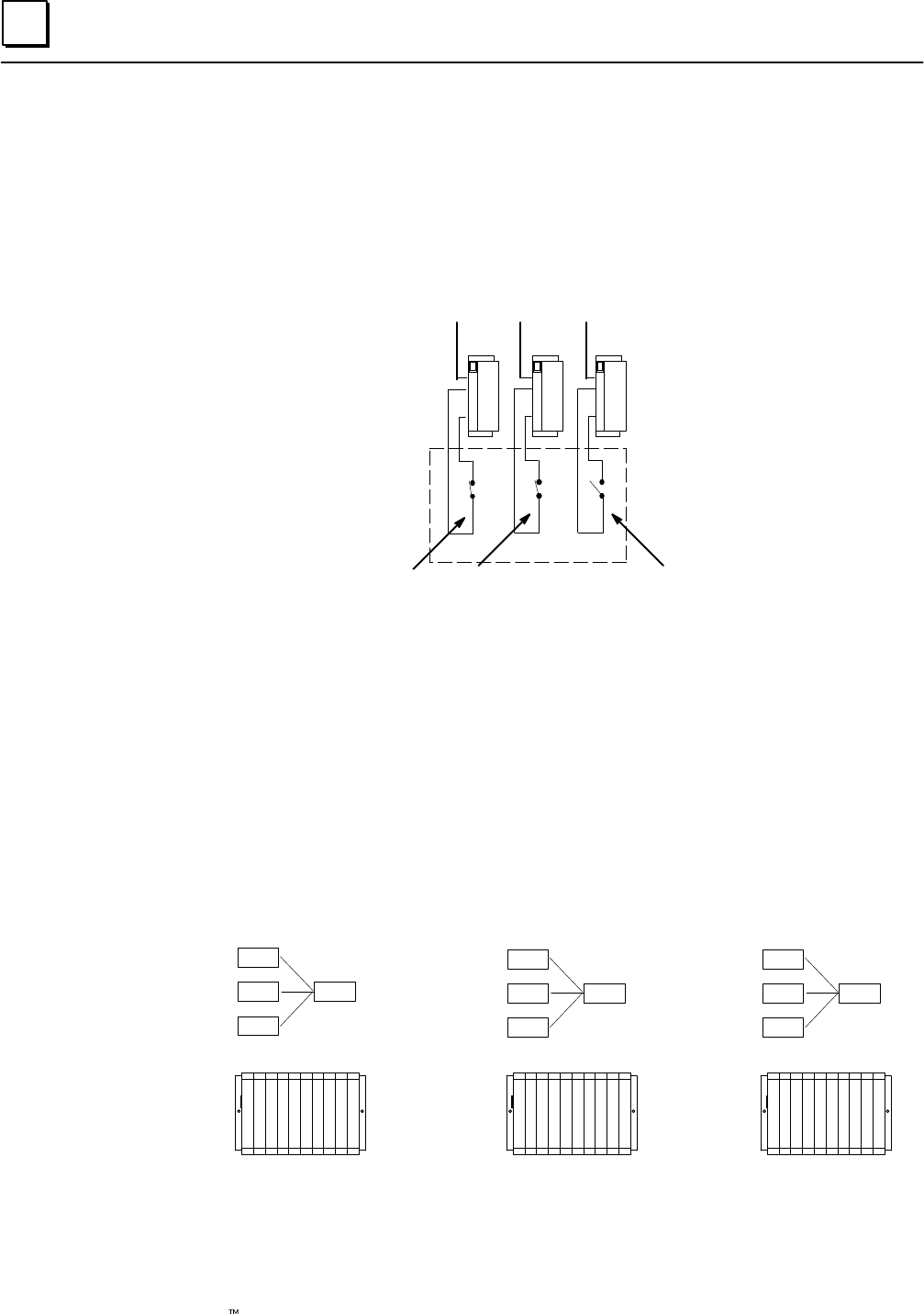
For this example, there are triple input sensors which are normally-on. However, one of
these input sensors is off:
Closed (1)
ABC
Open (0)
Each PLC in the example system votes on the input data received from these three
sensors as summarized below. For a more detailed description of input processing, see
chapter 2.
PLC Subsystem: Voting on Input Data
The example system uses three PLCs. Each PLC receives corresponding inputs from all
three blocks in the input group.
The GMR software in each PLC automatically votes on the input data and provides the
voted input to the application program (the program can also access the unvoted input
data). Each of these example voted inputs represents the same input sensors.
input A 1
input B 1
input C 0
voted
input
1
input A 1
input B 1
input C 0
voted
input
1
input A 1
input B 1
input C 0
voted
input
1
PLC A PLC CPLC B
If an input is faulty, the PLC(s) follow a configurable, predetermined voting scheme
based on the remaining input data.
1
1-7GFK-0787B Chapter 1 Introduction
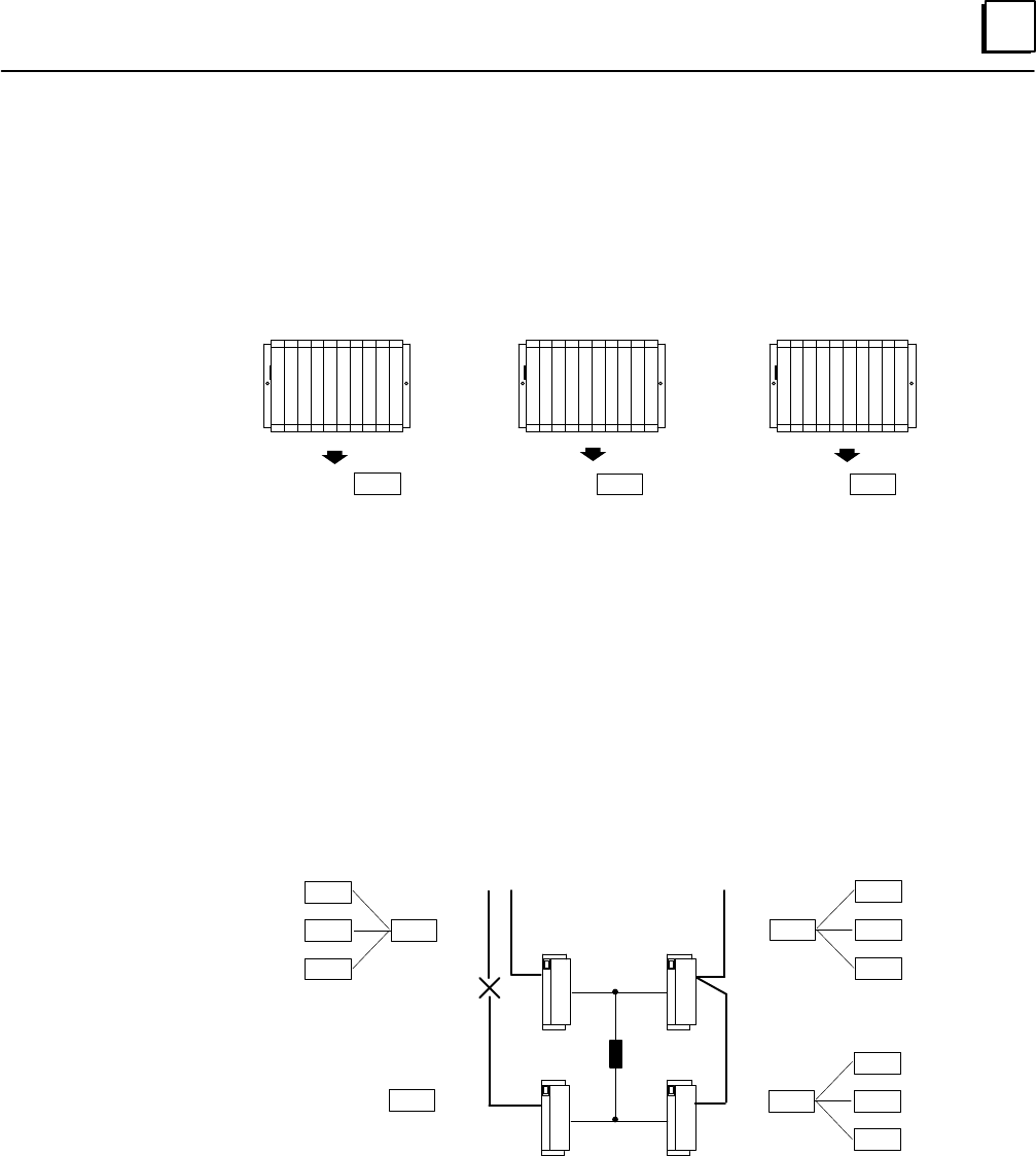
PLC Subsystem: Providing Output Data
Running the same application program, each PLC (referred to here by Genius Bus
Controller (GBC) serial bus addresses: 31, 30, and 29) processes the voted input data and
produces appropriate outputs. Because each of the three PLCs is running the same
program, they produce three copies of the same output data.
Each PLC then sends this triplicated output data on the bus.
output 1output 1output 1
GBC 31
GBC 31
GBC 31
GBC 30
GBC 30
GBC 30
GBC 29
GBC 29
GBC 29
PLC A PLC CPLC B
Output Subsystem
The basic element of an output subsystem is the output group. Each block in the group
has the same reference address in the application program, so each block receives the
same output data.
The output group votes on the three outputs and uses the result as the physical output.
In this example, communications are lost on bus C. Upon losing communications, the
block on bus C follows its configuration instructions, which are to default its outputs to 0.
However, the remaining blocks in the group continue to receive valid output data from
all three PLCs over busses A and B, and the actual state of the output load is controlled
properly. The loss of block or loss of bus diagnostic would be recorded, providing an aid
to troubleshooting and annunciating the problem.
C
output 31 1
1
1
voted
output
1
output 30
output 29
output 31
1
1
1
1output 30
output 29
voted
output
output 31
1
1
1
1output 30
output 29
voted
output
Load
AB
0
default
output
AB
CD
In a 4-block output group, each field output is supported by two Genius source outputs
connected in parallel on one side of the actuator and two Genius sink outputs connected
in parallel on the other. Each block in the group receives outputs from each of the three
separate processors.
Automatic System Test
Optional autotest routines test the complete system from input modules through to
output modules, including failures in the I/O wiring. Autotesting does not affect the
normal state of field devices.

1
1-8 Genius Modular Redundancy Flexible Triple Modular Redundant (TMR) System
User’s Manual – March 1995 GFK-0787B
Genius I/O Blocks
Inputs and outputs in a GMR system are provided by Genius I/O blocks. Some types of
Genius blocks are now enhanced for GMR operation. In addition, these and other types
of blocks can be included in a GMR system as “non-voted” blocks. Non-voted blocks are
individual blocks that are present on GMR busses in the system; they are not part of any
GMR input group or output group. They are included in the GMR configuration and
they may be autotested.
Discrete Blocks
All types of discrete blocks can be used as non-voted blocks in a GMR system.
The discrete blocks listed on page 1-2 are standard Genius blocks that are now
enhanced to include GMR functions. These blocks can be used in either GMR or
non-GMR systems. When configured for GMR operation (only), they perform output voting,
support GMR autotesting, and provide diagnostic reports to up to three PLCs. In
addition, certain of their operating parameters are changed when they are in GMR
mode.
Analog, RTD, and Thermocouple Blocks
Analog blocks can be included in the GMR configuration and used in GMR input groups,
as either voted or non-voted inputs. However, analog blocks in GMR input groups are
not autotested by the GMR software.
Analog blocks do not provide output voting, so they cannot be used in GMR output
block groups. However, they can be used as non-voted blocks in a GMR system, and
support standard Hot Standby Redundancy.
Analog, RTD, and Thermocouple blocks operate the same way in either GMR or non-GMR
systems. No specific versions of these blocks are required for GMR use.
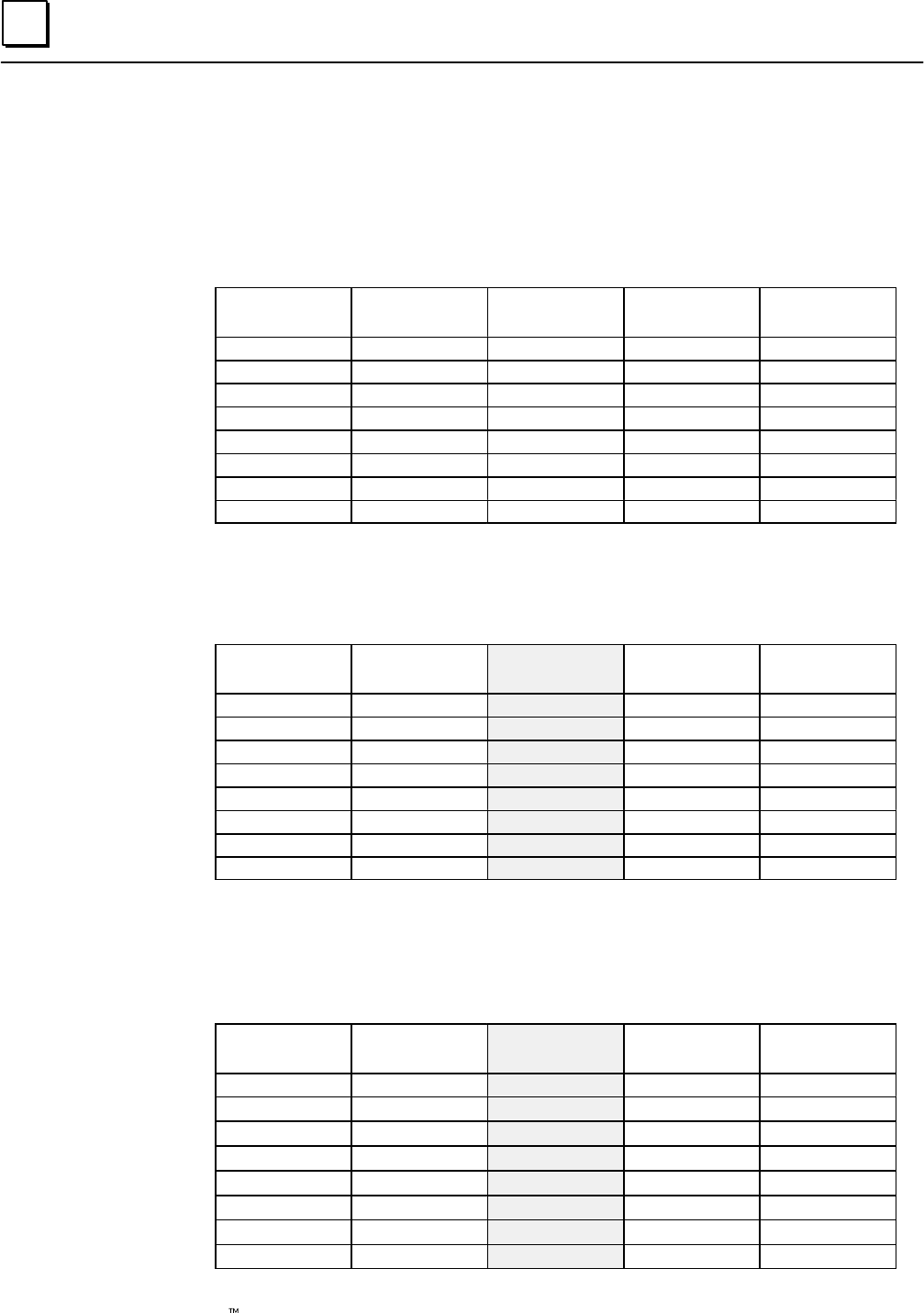
I/O Block Summary
The following table summarizes how different types of blocks can be used in a GMR system.
Basic Block Types Can be GMR
Input Block Can be GMR
Output Block Can be
“non-voted”
GMR block
Can be
Autotested Can be
non-GMR
block
24/48 VDC 16-Circuit Source block
24/48 VDC 16-Circuit Sink block
12/24 VDC 32-Circuit Source block
5/12/24 VDC 32-Circuit Sink block
yes yes yes yes yes
Any other discrete block no no yes no yes
Analog, RTD, and Thermocouple
blocks yes no yes no yes
High-speed Counter block no no no no yes
Power Trac block no no no no yes
1
1-9GFK-0787B Chapter 1 Introduction
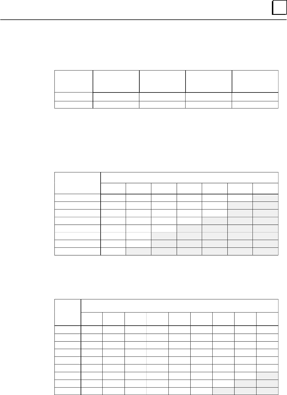
Number of I/O Points in a GMR System
The I/O capacity of the system depends on whether the CPU is a model 788 or model 789. For
most applications, these limits will not be reached. If you need help estimating I/O sizes for a
large application, contact GE Fanuc at 1-800-828-5747.
CPU Model Total Discrete
Physical I/O Maximum
Number of
Voted Inputs
Maximum
Number of
Voted Outputs
Maximum Total
Voted I//O
788 352 112 80 100
798 12288 2048 2048 4096
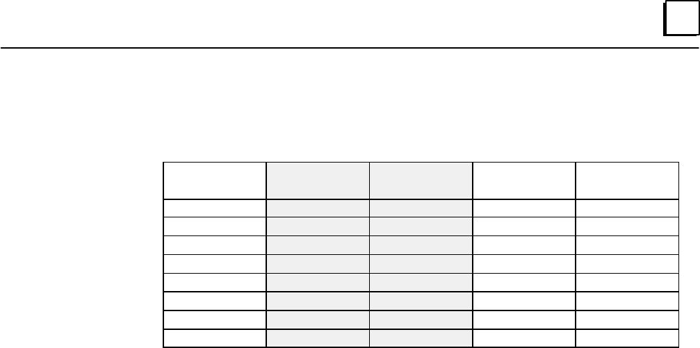
Non-GMR I/O: Non-GMR I/O is I/O that is not included in the GMR configuration. The
amount of non-GMR I/O that can be used depends on the amount of GMR I/O present and
the CPU memory capacity. The tables below show how much memory is available for
non-GMR I/O (main part of tables) for given numbers of GMR inputs and GMR outputs. In
the equations, the GMR Inputs and GMR Outputs are the actual number of I/O configured
with the programming software.
Number of Non-GMR I/O Available for the 788 CPU
Number of
Voted GMR
Number of Redundant GMR Outputs
Voted GMR
Inputs 0 16 32 48 64 80 96
0352 288 224 160 96 32
16 304 240 176 112 48
32 256 192 128 64 0
48 208 144 80 16
64 160 96 32
80 112 48
96 64 0
112 16
Number of Non-GMR I/O Available for the 789 CPU
These numbers are determined by the limits of physical I/O based on the Logicmaster
configuration and table size limitations based on the manner in which GMR maps I/O into
multiple locations in the I/O tables (this is explained in chapter 4).
Number
of Voted
GMR
Number of Redundant GMR Outputs
of Voted
GMR
Inputs 0 256 512 768 1024 1280 1536 1792 2048
012288 11264 10240 9216 8192 7168 6144 5120 4096
256 11264 10496 9472 8448 7424 6400 5376 4352 3328
512 10240 9728 8704 7680 6656 5632 4608 3584 2560
768 9216 8960 7936 6912 5888 4864 3840 2816 1792
1024 8192 7936 7168 6144 5120 4096 3072 2048 1024
1280 7168 6912 6400 5376 4352 3328 2304 1280 256
1536 6144 5888 5632 4608 3584 2560 1536 512
1792 5120 4864 4608 3840 2816 1792 768
2048 4096 3840 3584 3072 2048 1024
1
1-10 Genius Modular Redundancy Flexible Triple Modular Redundant (TMR) System
User’s Manual – March 1995 GFK-0787B
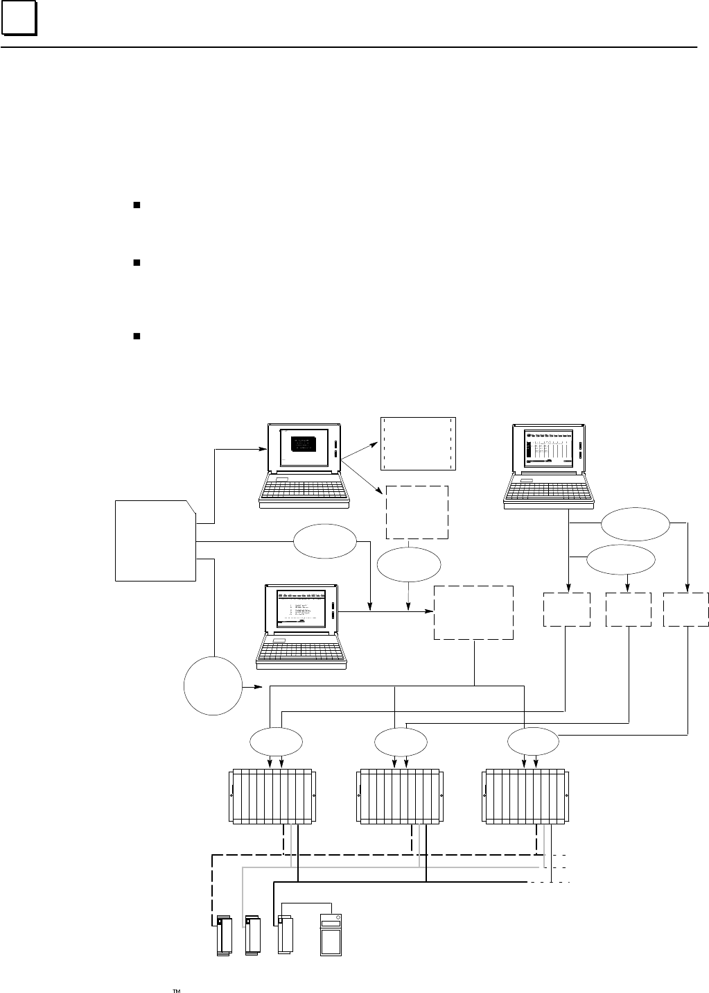
Configuration and Programming
The GMR Software
The GMR software consists of:
The GMR configuration software file, CONFIG.EXE. This file, which runs under DOS, is
used to enter the system parameters that will be used by the GMR system software. When
the GMR configuration is completed, it produces a Program Block named G_M_R10.
A directory named GMRxxyy containing the GMR system software files, to which
the application program will be added. In the directory name GMRxxyy, xx is two
digits representing the major revision level of the GMR software. The last two digits
(yy) represent the minor software revision level.
A “teach” file named KEY0.DEF for use in future application program updates.
Subsequent chapters of this book explain configuration steps and programming
guidelines for a GMR system. The basic steps are illustrated below.
CONFIG.EXE
GMRxxyy
KEY0.DEF
GMR CONFIGURATION
GMR
Configuration
Printout
G_M_R10
Program
Block
LM90 CONFIGURATION
CONFIGBCONFIGA
LM90 PROGRAMMING
The
Application
Program
LM90
Librarian
LM90
Copy Folder
PLC A PLC B PLC C
CONFIGC
GMR
Diskette
LM90
Copy Folder
LM90
Copy Folder
LM90
Store LM90
Store
LM90
Store
future
program
updates
I/O Block Configuration with
Hand-held Monitor
1
1-11GFK-0787B Chapter 1 Introduction
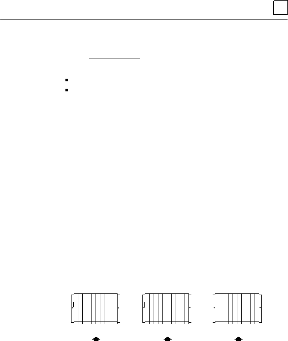
The Basic Steps of Configuration and Programming
1. Use the GMR configuration software to complete the GMR configuration. There is
only one GMR configuration needed for the system. GMR configuration sets up the
parameters that will be used by the system, including reference addresses. The GMR
configuration software produces:
A printout of the GMR Configuration.
A program block named G_M_R10. This is later added to the application program.
2. Using the LM90 configuration software, create a Logicmaster configuration for
each PLC. The easiest way to do that is to:
A. Create a Program Folder for PLC A. With the GMR configuration printout as a
reference, complete its Logicmaster configuration.
B. Use the Copy Folder feature of the Logicmaster 90 programming software to
copy the configuration of PLC A to additional folders for PLC B and PLC C.
C. Edit the configurations for PLC B and PLC C as necessary.
3. Using a Hand-held Monitor, complete the Genius block configuration. Genius block
configuration sets up the operating characteristics of each block in the GMR system.
4. Using the Logicmaster 90 programming software, create the application program.
While there can be up to three PLCs in a GMR system, each of which has a slightly
different configuration, there is normally only one application program.
A. Using Logicmaster 90, copy the folder named GMRxxyy (for example,
GMR0101) from the GMR software diskette to a program folder with your
application program name (such as GMRPROG).
B. Using Logicmaster 90, add program block G_M_R10 (created with the
configuration utility) to the application program folder.
C. Create or add the application program logic in this folder.
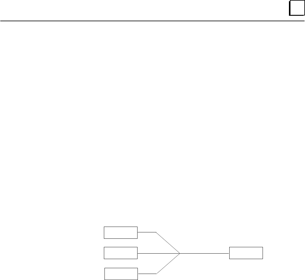
5. After completing the application program and the configuration(s), store them to
the PLCs. As explained above, all redundant PLCs in the GMR system normally use
the same application program, but different configurations:
PLC A PLC B PLC C
Program: GMRPROG
Configuration: CONFIGA Program: GMRPROG
Configuration: CONFIGB Program: GMRPROG
Configuration: CONFIGC
Supplying the configuration and program as separate files, as shown, makes it easier
to perform program updates in the future.
The GMR Configuration Software allows the system to be set up for online program
changes. Online changes are intended for system debug and commissioning.
2section level 1 1
figure bi level 1
table_big level 1
2-1
GFK-0787B
Chapter 2Input Subsystem
This chapter provides information about the inputs to a GMR system.
Overview
GMR Input Groups
Non-Voted I/O in the Input Subsystem
Discrete Inputs
Types of Blocks in the Input Subsystem
Discrete Input Processing
Discrepancy Reporting for GMR Inputs
Input Autotest for GMR Inputs
Line Monitoring for Discrete Inputs
Manual Input Controls
Analog Inputs
Voted Analog Inputs
Analog Discrepancy Reporting
Non-Voted Analog Inputs in GMR Input Groups
Non-GMR Analog Blocks
2
2-2 Genius Modular Redundancy Flexible Triple Modular Redundant (TMR) System
User’s Manual – March 1995 GFK-0787B
Overview
The input subsystem is the part of a GMR system that gathers input data. It may consist of:
GMR Input groups of 1 to 3 discrete or analog blocks
Individual non-voted discrete and analog blocks
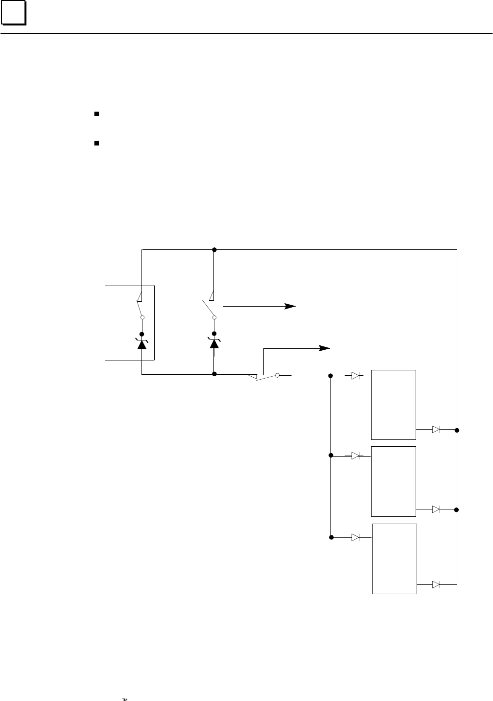
The following illustration represents basic elements of an input subsystem.
Triple Input Sensors
Triple Genius Busses
Triple PLCs
ABC
Input Block Group
Non-voted
(non-redundant)
Input Block
GMR blocks are arranged in “groups” of 1, 2, or 3 blocks. Within a group, all the blocks must be
the same type. The input group shown above consists of three Genius blocks. Each has its own
input sensors monitoring the same parts of the application process. Each block sends the input
data from its sensors to three Series 90-70 PLCs. For simplification, the illustration only shows one
input circuit on each block. However, each group can serve multiple GMR inputs. In addition,
circuits that are not needed for GMR inputs can be used for non-voted inputs or outputs.
Genius blocks broadcast their inputs. So each block’s input data is received by all PLCs on the
bus. The GMR system software in each PLC then performs input voting and provides the results
to its application program. If all input data is not available, the software follows a configured
voting adaptation scheme. Details of both discrete and analog input voting are in the PLC
chapter.
In addition to the diagnostics capabilities of the Series 90-70 PLC and Genius I/O blocks,
the GMR system provides autotesting and discrepancy reporting for GMR inputs.
Genius blocks configured for GMR operation automatically generate three copies of
their standard Genius fault report messages. They send one copy to the PLC Bus
Controller configured with serial bus address 31, one to 30, and one to 29. So all of the
GMR PLCs are able to monitor the blocks for Genius diagnostics.
2
2-3GFK-0787B Chapter 2 Input Subsystem
GMR Input Groups
The configuration can include as many as 128 16-circuit voted discrete and 256 four-input analog
input groups. (The actual I/O capacity of the system depends on the CPU type. See page 1-9).
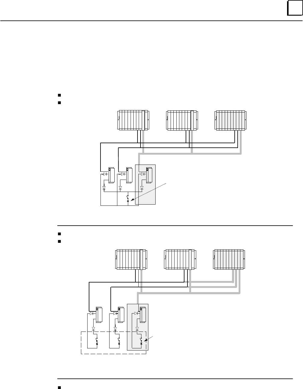
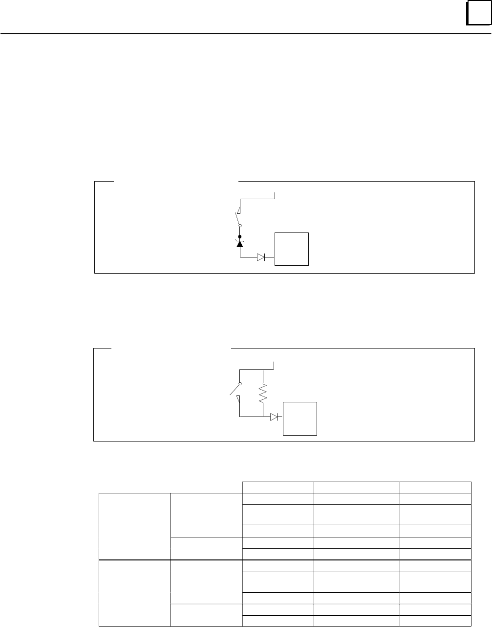
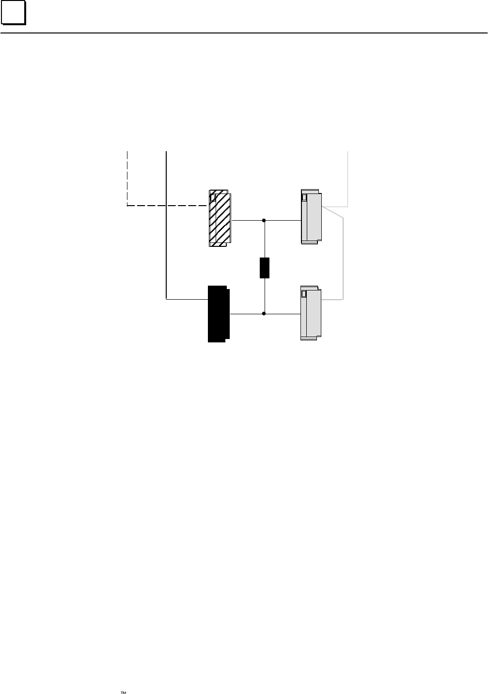
In an system that has normally-energized discrete inputs, the following combinations of
sensors and Genius inputs can be used with Genius Modular Redundancy.
one sensor to three Genius inputs, three busses, three PLCs
one sensor to two Genius inputs, two busses, two PLCs
One Input Sensor
Triple Genius Busses
Triple PLCs
Optional Zener
diode for line
monitoring
Shaded items omitted
for duplex operation
three sensors to three Genius inputs, three busses, three PLCs
two sensors to two Genius inputs, two busses, two PLCs
Triple Input Sensors
Triple Genius Busses
Triple PLCs
Optional Zener
diodes for line
monitoring
Shaded items omitted
for duplex operation
one sensor to one Genius input
Single blocks can be configured as non-voted GMR blocks, allowing them to take
advantage of the GMR autotest feature. Both discrete and analog blocks can be used;
however, analog blocks cannot be autotested.
2
2-4 Genius Modular Redundancy Flexible Triple Modular Redundant (TMR) System
User’s Manual – March 1995 GFK-0787B
Non-Voted I/O in the Input Subsystem
The input subsystem can also include three types of non-voted inputs:
Inputs from single-block (simplex) GMR input groups
Individual blocks can be included in the GMR configuration as “simplex groups”,
and can utilize the GMR features such as autotesting. Inputs from simplex blocks are
placed into the area of the Input Table used for GMR inputs.
Inputs from non-GMR I/O blocks
“Non-voted” blocks are individual blocks that are present on a GMR bus and are
included in the GMR configuration. However, their inputs are not voted on by the
PLC(s), and are located in a different area of the Input Table.
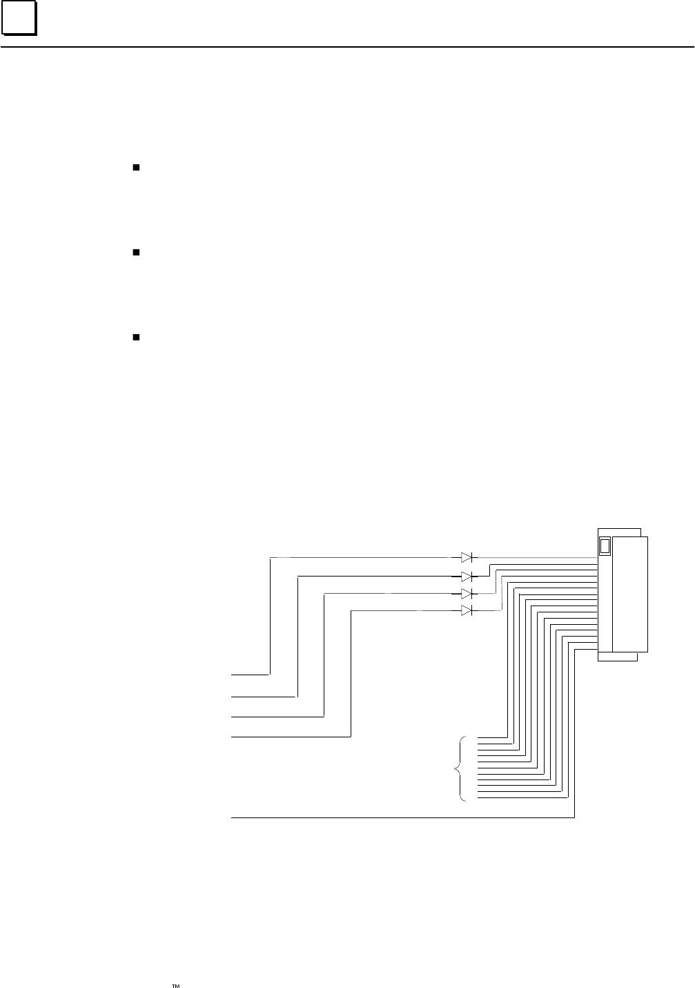
Non-voted points on individual blocks in a multiple-block GMR input group
Non-voted I/O points may be placed within a voted input group, to take advantage
of unused circuits. These extra circuits can be used as either inputs or outputs. If the
group utilizes GMR autotesting of inputs, circuit 16 on each block, which is required
for autotest, cannot be used for non-GMR I/O.
Example: a discrete input group consisting of three 16-circuit blocks has only four
voted inputs. That leaves circuits 5 through 15 on each block for use as non-GMR
inputs or outputs. Circuit 16 is used for the autotest feature.
1st GMR input
2nd GMR input
3rd GMR input
4th GMR input
GMR Autotest
Can be used as
non-GMR inputs
and outputs
Block A
Blocks B and C are the same
Individual input points used in this way can be autotested if autotesting is set up as
part of their GMR configuration.
2
2-5GFK-0787B Chapter 2 Input Subsystem
Discrete Inputs
Types of Blocks in the Input Subsystem
The following discrete block versions can be configured for GMR version 2.06 operation
and used as GMR input blocks:
24/48 VDC 16-Circuit Source block: IC660BBD020M or later
24/48 VDC 16-Circuit Sink block: IC660BBD021M or later
12/24 VDC 32-Circuit Source block: IC660BBD024N or later
5/12/24 VDC 32-Circuit Sink block: IC660BBD025N or later
All types of Genius blocks can be used as non-GMR blocks in a GMR system.
Note that the GMR Input Autotest feature requires point 16, so if the system uses Input
Autotest, point 16 is not available as an I/O point for the application (leaving either 15 or 31
points available on the blocks listed above).
Discrete Input Processing
Discrete input processing is handled in each PLC, by the GMR system software. The
manner in which inputs are handled depends upon whether a block is included in the
GMR configuration, and if it is, upon whether it is part of a 3-block, 2-block, or 1-block
group. Input processing by the PLC is explained in detail in the PLC chapter. In general,
the GMR system software compares input data from all corresponding inputs (3, 2, or 1)
for each point, and provides a voted input result for use by the application program. If
all the input data is not available, the GMR system software follows a configured voting
adaptation scheme. The application program can also access the original, unvoted input
data, along with any non-GMR inputs that have been included in the input subsystem.
Field Input Data
Input A
Input B
Input C
0
0
1GMR Software Performs
2 out of 3 Voting
0
Single Input Pro-
vided to Applica-
tion Logic
Discrepancy Reporting for GMR Inputs
For GMR inputs, if there is a discrepancy between the original input data for an input
and the voted input state, the GMR software automatically places a message in the I/O
Fault Table, where it is available to the Logicmaster 90 software and the application
program logic. This is also described in more detail in the PLC chapter. Fault bits are also
set for input discrepancies. These fault bits are available for use in the application
program, for further annunciation or corrective action.
Discrepant signals are filtered for a configurable time period, to eliminate transient
discrepancies caused by timing differences.
2
2-6 Genius Modular Redundancy Flexible Triple Modular Redundant (TMR) System
User’s Manual – March 1995 GFK-0787B
Input Autotest for GMR Inputs
During GMR configuration, input autotesting can be individually turned on or off for each
input in an input group. The GMR software will automatically test the selected inputs for the
ability to reach the alarm state. The ability to diagnose short circuits on inputs depends on
whether the circuit is set up as a bistate or tristate input, and on whether the block itself is
configured for GMR mode (using the Hand-held Monitor).
Autotesting checks the ability of the input electronics to recognize both the On and
the Off state. During each Input Autotest, some inputs are forced to the Off state by
de-energizing the power feed output, and some are forced to the On state via the
Genius block electronics. See page 5-6 for more detailed information.
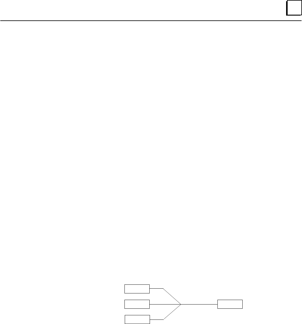
Input autotesting also detects circuit-to-circuit shorts.
Note: blocking diodes are required to use the Input Autotest feature. These diodes
are in addition to a Zener diode that may be added for line monitoring.
Source
Genius
Block
+24V
Optional Zener diode
for line monitoring
See page 5-6 for more detailed information about input autotesting. Also see pages 8-3
through 8-9 for Autotest wiring information.
Calculating Voltage Drops on Tristate Inputs
It is important to consider the field wiring runs required for devices configured as
tristate inputs. Devices that are powered by 24V DC will have a voltage-reducing
component inserted at the field device to provide an input threshold range for three
states. The table on the next page shows appropriate ranges. Wiring runs can reduce the
voltage at the input block terminal further, to an inoperable level, depending on the
length, conductor, and gauge. Isolation diodes placed before the terminal on the input
will also drop the voltage.
Most applications do not have limitations created by these factors. However, to ensure
that all input state operations are indicated correctly, calculations should include the field
signal voltage, the wire resistance times the length and the voltage drop in any barriers
or isolation devices, to determine the actual voltage present at the input terminal.
Additional information about input blocks is located in the Genius I/O Discrete and Analog
Blocks User’s Manual (GEK-90486-2).
2
2-7GFK-0787B Chapter 2 Input Subsystem
Line Monitoring for Discrete Inputs
Normally-closed inputs on GMR-configured blocks can be monitored for short circuit
faults. Normally-open inputs on blocks which are not configured in GMR mode can be
monitored for open circuit faults.
Normally-closed Inputs
For applications such as Emergency Shutdown (ESD), normally-closed inputs are generally
monitored for short circuits across the lines, since that represents a fail to danger condition
(that is: trip is not detected). In general, these inputs are powered from +24V, and a field
short to ground is interpreted as a trip condition.
Source
Genius
Block
+24V
Typical Normally-closed Input
Normally-open Inputs
For applications such as Fire and Gas Detection, normally-open inputs are generally
monitored for open circuits on the lines, since that represents a fail to danger condition
(that is: trip is not detected). In general, these inputs are powered from +24V, and a field
short to +24V is interpreted as a trip condition.
Source
Genius
Block
Typical Normally-open Input +24V
When a block is configured (with a Hand-held Monitor) as a GMR block, its input thresholds
change to those listed below.
Input Voltage Input Status Input State
Source Blocks
tristate inputs
<30% Vdc off 0
Source Blocks
tristate inputs
>50% Vdc
< Vdc–7V on 1
< Vdc–4V short circuit fault 1
bi-state inputs
<30 Vdc off 0
bi-state inputs
>50% Vdc on 1
Sink Blocks
tristate inputs
<4V short circuit fault 1
Sink Blocks
tristate inputs
>7V
<50% Vdc on 1
>70% Vdc off 0
bi-state inputs
<50% Vdc on 1
bi-state inputs
>70% Vdc off 0
Input Filter Time
For any circuit configured as a tristate input, the Input Filter Time configured for the block
(using a Hand-held Monitor) must be at least 30mS.
2
2-8 Genius Modular Redundancy Flexible Triple Modular Redundant (TMR) System
User’s Manual – March 1995 GFK-0787B
Manual Input Controls
Safety systems often use controls for manual trip and manual inhibit. The GMR autotest and
fault processing operations are unaffected by such controls.
A manual trip causes the input to assume the alarm condition. For example, for a
normally-energized input, the input is open circuit.
A manual inhibit causes the input to remain in the normal condition. For example,
for a normally-energized input, the input is held high even if the device is in the Off
state.
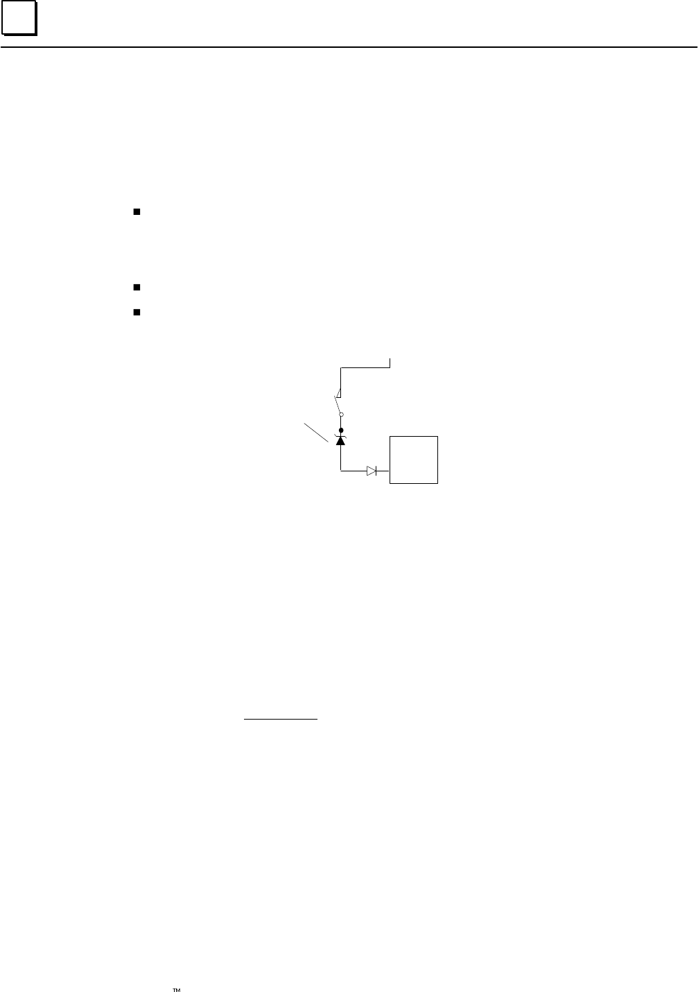
These manual controls can be implemented either in hardware or in software.
Hardware control usually consists of switch contacts applied to the input circuit, as shown
below for a normally-energized input. Repeat contacts of the control switches are often input
into the system for reporting purposes.
Source
Genius
Block
System Input
Manual Trip
Manual Inhibit
Field
Circuit
point 1
point 16
System Input
Source
Genius
Block
point 1
point 16
Source
Genius
Block
point 1
point 16
2
2-9GFK-0787B Chapter 2 Input Subsystem
Analog Inputs
Like discrete blocks, analog blocks can be used in the input subsystem as members of
GMR input groups of 1 to 3 blocks, or as non-voted blocks. Also like discrete blocks,
individual circuits of analog blocks in multiple-block GMR input groups can be used as
non-voted analog inputs.
Analog blocks in GMR input groups are not autotested by the GMR software.
All of the available types of analog blocks can be used, including the Thermocouple and
RTD blocks. See the Genius I/O Discrete and Analog Blocks User’s Manual for information
about the various analog Genius blocks.
The application program can reference all analog inputs directly, whether they are
located in the non-voted analog inputs area or not.
Voted Analog Inputs
For voted analog inputs, analog blocks must be set up as 2-block or 3-block input groups.
The input values are in engineering units.
For a 3-block group, the GMR software compares the three corresponding inputs for
each channel and selects the intermediate value. This value is made available to the
application program. The application program can also access the original input values.
Field Input Data
Input A
Input B
Input C
152
150
110
PLC Selects the
Intermediate Value
150
Single Input Provided
to Application Logic
For example, in the illustration above, inputs A, B, and C might represent the first
channel on each block in a three-block group. The PLC would place the selected input
value into the first voted input word for that group.
Number of Input Sensors per Voted Channel
For each voted input channel in a 3-block group, either single or triple input sensors that
are compatible with the input drive requirements of the Genius blocks can be used.
Current-loop (4-20mA) devices must be converted to voltage when a single sensor is
used.
Analog Voting Adaptation
If a failure (discrepancy fault, or Genius fault) occurs, the GMR software rejects the
faulty data. Depending on the configuration of the input group, input voting may go
from three inputs to two inputs to one input, or from three inputs to two inputs to the
configured default value.

2
2-10 Genius Modular Redundancy Flexible Triple Modular Redundant (TMR) System
User’s Manual – March 1995 GFK-0787B
Analog Discrepancy Reporting
When the GMR software compares analog input data, it checks each channel against
discrepancy limits provided as a part of the configuration for that input group. Any
channel that varies by more than a configurable percentage from the intermediate value
is reported.
Discrepancy signals are filtered for a configurable time period, to eliminate transient
discrepancies caused by timing differences.
Non-Voted Analog Inputs in GMR Input Groups
If a system includes analog inputs that do not require redundancy, they are usually
located on individual analog blocks. However, they can also be located on channels of
blocks in a GMR analog input group that do not require redundancy. For example, a
group of three 6-channel analog input blocks might use only four voted inputs on each
block. That would leave inputs 5 and 6 available for connection to other sensors not
requiring voting.
Non-GMR Analog Blocks
Individual analog blocks can be used as input blocks or combination input/output blocks.
All of the operating features of these blocks are available.
Individual non-voted analog blocks can be included in the GMR configuration.

3section level 1 1
figure bi level 1
table_big level 1
3-1
GFK-0787B
Chapter 3Output Subsystem
This chapter describes GMR output subsystem.
Overview
Types of Blocks in the Output Subsystem
GMR Output Handling
Output Voting
Duplex Default for Outputs
Output Forces and Overrides
Output Fault Reporting
4-Block Output Groups
Output Load Sharing
Manual Output Controls and Diagnostics
Redundancy Modes for Output Blocks
GMR Mode
Hot Standby Mode
3
3-2 Genius Modular Redundancy Flexible Triple Modular Redundant (TMR) System
User’s Manual – March 1995 GFK-0787B
Overview
The output subsystem is the part of a GMR system that provides output data. It may consist of:
GMR Output groups of 4 discrete blocks
Individual non-GMR discrete and analog blocks
The following illustration represents basic elements of an output subsystem.
Load
4-Block Output Group
No redundancy
or
Hot Standby
or
Duplex
ABC ABC ABC
AB
DC
In a 4-block output group, each field output is supported by two Genius source outputs
connected in parallel on one side of the actuator and two Genius sink outputs connected
in parallel on the other. Each block in the group receives outputs from each of the three
separate processors. Three Genius busses are used.
Individual Genius blocks can also be connected to the system. These blocks may be
configured for either hot standby or duplex CPU redundancy if desired.
Types of Blocks in the Output Subsystem
The following discrete block versions can be configured for GMR operation. They will
perform output voting and autotesting when used in GMR mode:
24/48 VDC 16-Circuit Source block:
24/48 VDC 16-Circuit Sink block:
12/24 VDC 32-Circuit Source block.
5/12/24 VDC 32-Circuit Sink block:
IC660BBD020M
IC660BBD021M
IC660BBD024N
IC660BBD025N
3
3-3GFK-0787B Chapter 3 Output Subsystem
GMR Output Handling
Unlike GMR input voting, which is done by the GMR software in the PLCs, output voting is
performed at the output block groups. To perform output voting, the blocks must be one of the
listed types, and they must be configured (with a Hand-held Monitor) to be in GMR mode.
Output Voting
A GMR output block group compares corresponding output data for each point as
received from each of the three PLCs. If all three PLCs are online, the data from at least
two must match. The block group sets each output load to match the state commanded
by at least two of the PLCs.
Outputs from 3 PLCs
PLC A
PLC B
PLC C
0
0
1
GMR Block Performs
2 out of 3 Voting
0
Single Output
Provided to
Field Device
If only two of the three PLCs are communicating on the bus and they send matching
output data for a point, the block group sets the output to that state.
If only two PLCs are communicating, the block group performs 2 out of 3 voting using
the data from the two online PLCs and the block’s configured duplex default state in
place of the offline PLC data.
If only one of the three bus controllers is present on the bus, the block group sets output
states to match the output data sent by that PLC.
If the Simplex Shutdown feature is enabled, a PLC will shut down if it determines that it
is the only PLC still operating. The timeout period before it shuts down is configured as
the next item. When the PLC shuts down and a block group is no longer receiving
output data, outputs will go to their default state or last state, as configured at each block
group.
If all PLCs are offline, the block group forces its outputs to the block’s configured default state.
The voted state of the output is available to the GMR system for monitoring purposes to
determine output discrepancies. However, the voted output state is not available to the
application program.
Duplex Default for Outputs
As mentioned, the duplex default state is used when a block determines that only two PLCs
are online. The Duplex Default state of On or Off is used by the 2 out of 3 voting algorithm
in the block group, instead of the state that would have been supplied by the third PLC.
The Duplex Default state determines whether voting will be 1 out of 2 or 2 out of 2 when
only two PLCs are providing outputs. This is explained on the next page.
3
3-4 Genius Modular Redundancy Flexible Triple Modular Redundant (TMR) System
User’s Manual – March 1995 GFK-0787B
The following three tables compare voting results for a block group receiving outputs
from all three PLCs with results when one of the three PLCs is offline.
Results of Block Group Voting with Three PLCs Online
For comparison, this table shows how a block group votes on outputs received from
three PLCs when all three are online. The block group doesn’t use the Duplex Default, so
it is shown as an X (don’t care).
PLC A Output
State PLC B Output
State PLC C Output
State Duplex Default
Setting in Block Output State
0 0 0 X 0
0 0 1 X 0
0 1 0 X 0
0 1 1 X 1
1 0 0 X 0
1 0 1 X 1
1 1 0 X 1
1 1 1 X 1
Results of Block Group Voting with Two PLCs Online, and Duplex Default Set to 1
If one PLC is offline, the outputs from both online PLCs must be 0 for the voted output
state to be 0. The voted output is 1 if either of the online PLCs outputs a 1.
PLC A Output
State PLC B Output
State PLC C Output
State Duplex Default
Setting in Block Output State
0 0 1 0
0 0 1 0
0 1 1 1
0 1 1 1
1 0 1 1
1 0 1 1
1 1 1 1
1 1 1 1
Results of Block Group Voting with Two PLCs Online, and Duplex Default Set to 0
If one PLC is offline, the inputs from both online PLCS must be 1 for the voted output to
be 1. The voted output is 0 if either of the online PLCs outputs a 0.
PLC A Output
State PLC B Output
State PLC C Output
State Duplex Default
Setting in Block Output State
0 0 0 0
0 0 0 0
0 1 0 0
0 1 0 0
1 0 0 0
1 0 0 0
1 1 0 1
1 1 0 1
3
3-5GFK-0787B Chapter 3 Output Subsystem
Results of Block Group Voting with One PLC Online
If two PLCs are offline, the “voted” outputs are the same as the outputs from the PLC
which is still online (x = don’t care).
PLC A Output
State PLC B Output
State PLC C Output
State Duplex Default
Setting in Block Output State
0 x 0
0 x 0
0 x 0
0 x 0
1 x 1
1 x 1
1 x 1
1 x 1
PLC Logon Control
To prevent untripping of tripped block outputs, blocks do not use output data from a
PLC that has previously been offline until one of the following occurs:
A. all of the output data received from the newly-online PLC agrees with the voted
output data of the block.
B. the user forces the PLC to log onto the output block(s) by turning on the GMR
control bit FORCLOG (Force Logon).
For more information about PLC Logon control, please see page 7-17.
Output Fault Reporting
On detection of any block or circuit fault, a directed fault message is transferred to the
three PLCs on an event-driven basis.
The PLC currently operating as the Autotest Master also monitors output blocks for
discrepancies between the output values commanded by the PLCs. If a PLC is offline, its
data is not considered “discrepant”. But if a PLC is online and its data is discrepant, the
GMR software logs a fault into the I/O Fault Table of the PLC that detects the
discrepancy which is copied to the other PLCs. The appropriate fault references are also
set in each PLC.
3
3-6 Genius Modular Redundancy Flexible Triple Modular Redundant (TMR) System
User’s Manual – March 1995 GFK-0787B
4-Block Output Groups
All four blocks in a group must be either 16-circuit or 32-circuit blocks. In a group, two
source-type Genius blocks are connected in parallel on one side of each load, and two
sink-type Genius blocks are connected in parallel on the other side.
Load
Source Blocks
(IC660BBD020
or
IC660BBD024)
Sink Blocks
(IC660BBD022
or
IC660BBD025)
Bus A Bus B
Bus C
AB
CD
There are three busses. One source block and one sink block are connected to either bus
A or bus B (see blocks B and D on bus B in the illustration above). The other two blocks
are connected to the remaining two busses (A and C above).
The illustration shows just one load for a group of four blocks. However, up to 16 loads
could be controlled by the same group of four blocks (using 16-circuit blocks).
When the blocks are configured, each is assigned the same output reference addresses
using Logicmaster 90. Then, the blocks are configured for GMR mode using the Genius
Hand-held Monitor.
Output circuits that are to be autotested must be able to withstand the On and Off pulse
times used by the test. Check each output device’s characteristics against the
specifications listed on page 8-12 (for 16-point blocks) and page 8-17 (for 32-point blocks)
to verify that it can be autotested and/or used in a 4-block output group.
Output Load Sharing
In a 4-block output group, current to output loads is shared. Therefore, it is not possible
to be sure exactly how much power is being provided by each block. If 16-circuit blocks
in a GMR output group are configured for No Load fault reporting, the minimum
connected load that can be used is 100mA. If blocks in a 4-block output group are
configured for No Load reporting, a system output No Load fault will only be reported if
both of the source blocks or both of the sink blocks report No Load faults.

3
3-7GFK-0787B Chapter 3 Output Subsystem
Operation of a 4-Block Output Group
Each GMR output state is sent to four blocks set up in an H-pattern as shown on the
opposite page. This type of grouping creates a fault-tolerant system where any single
point of failure does not cause the system to lose control of a critical load. This is
achieved by:
output voting (which is explained on page 3-3), and
the electrical characteristics of sink and source blocks, and
redundant busses.
Electrical Characteristics of Sink and Source Blocks
If a load is wired between a sink and source block, both the sink output and the source
output must be active to control the load. If either the sink output or the source output
fails On, turning the other Off, turns the load Off. Doubling the number of blocks to
four and putting them in an H pattern means that if any single point of failure occurs,
the system can still control the load.
The following chart shows how the GMR system uses the 4-block H-pattern output
group to maintain control of critical loads following certain types of failures. All
operating blocks receive the same I/O data, because within a fault-tolerant 4-block
H-pattern group, all four blocks are configured at the same output address. The chart
indicates which blocks actually affect the state of the load under different fault scenarios.
All operating blocks act on the I/O data received.
Other Blocks Used Other Blocks Used
Fault To Turn the Load Off To Turn the Load On
output at block A fails On turn outputs at block C and D Off turn output at block C or D On
output at block A fails Off turn output at block B off turn output at block B and either C or D On
output at block B fails On turn outputs at block C and D Off turn output at block C or D On
output at block B fails Off turn output at block A off turn output at block B and either C or D On
output at block C fails On turn outputs at block A and B Off turn output at block A or B On
output at block C fails Off turn output at block D off turn output at block D and either A or B On
output at block D fails On turn outputs at block A and B Off turn output at block A or B On
output at block D fails Off turn output at block C off turn output at block C and either A or B On
Bus Redundancy in a 4-Block Output Group
If one of the three busses in an output group is damaged or cut, there is still I/O data
communicated to at least one sink output and one source output to control the load.
When a block loses communication with all the PLCs, its outputs go to a default state. If
the default state is Off, the system is fault-tolerant as shown in the following chart.
Fault To Turn the Load Off or On
bus A fails busses B and C still provide I/O communications to blocks B, C, and D;
turning outputs at those blocks On or Off turns the load On or Off.
bus B fails busses A and C still provide I/O communications to blocks A and C; if the
block B and D outputs are configured to default Off, turning output at
blocks A and C On or Off turns the load On or Off.
bus C fails busses A and B still provide I/O communications to blocks A, B, and D;
turning outputs at those blocks On or Off turns the load On or Off.
3
3-8 Genius Modular Redundancy Flexible Triple Modular Redundant (TMR) System
User’s Manual – March 1995 GFK-0787B
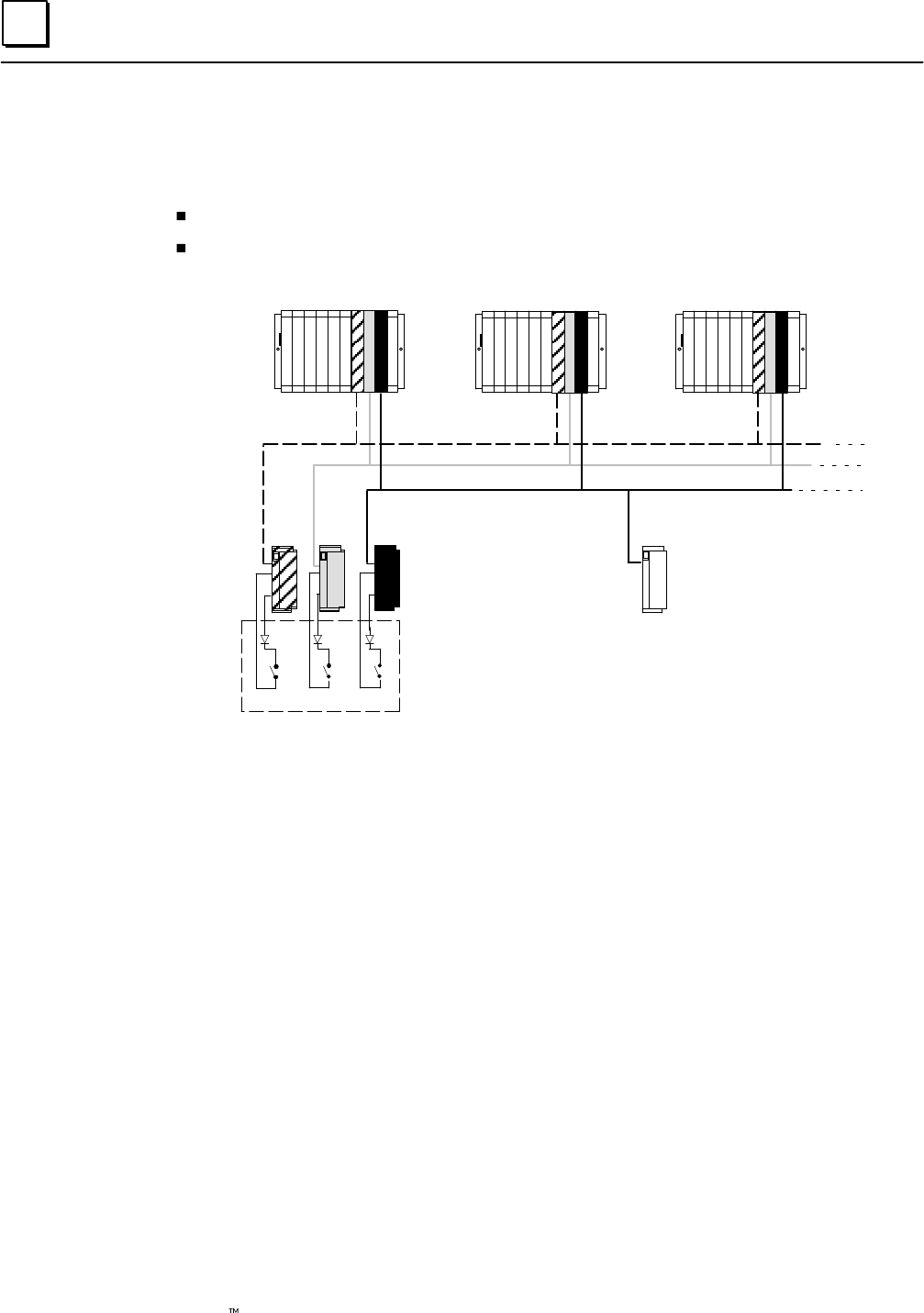
Manual Output Controls and Diagnostics
Safety systems are often provided with controls for manual trip and manual override.
A manual trip causes the output to assume the alarm condition. For example, a
normally-energized output would be de-energized.
A manual override causes the output to remain in the normal condition. For
example, a normally-energized output is held energized.
These manual controls can be implemented either in hardware, as represented below, or in
software. If the software method is used, GMR autotest and fault processing operations are
unaffected.
Hardware control usually consists of switch contacts applied to the output circuit, as shown
below (for a normally-energized output).
Source
Genius
Block
Source
Genius
Block
Sink
Genius
Block
Sink
Genius
Block
Manual
Override
+24V
System Input Manual Trip
System Input
Manual
Override
LOAD
+0 VDC
In this circuit, operation of either the trip or override switch can cause no-load faults, state
faults, and autotest faults to be generated. In the GMR system, fault reporting can be
modified to suppress no-load faults and state faults by wiring additional inputs that reflect
the states of the manual override and manual trip input switch to the GMR system. The GMR
system then takes these into account before reporting faults. Use of manual controls does not
affect fault reporting for Short Circuit, Overtemperature, Overload, or Discrepancy faults.
(see chapter 5, “Monitoring Manual Output Controls”).

3
3-9GFK-0787B Chapter 3 Output Subsystem
Redundancy Modes for Output Blocks
There are three separate configuration processes for a GMR system:
GMR configuration, which supplies parameters used by the GMR system software.
PLC configuration, which is performed as usual for a Series 90-70 PLC system using
the Logicmaster 90 software.
Genius block configuration, which sets up the operating characteristics of the blocks
themselves.
It is during Genius block configuration that the redundancy mode of blocks is selected.
This is particularly relevant to the operation of output blocks. The four possible choices
for redundancy mode are:
A. GMR
B. Hot Standby PLC Redundancy
C. Duplex PLC Redundancy
D. No PLC Redundancy
Blocks in an output group must be set up for GMR mode. This changes the operating
characteristics of the block as described.
Individual output blocks (or combination I/O blocks) can be set to any of the latter three
modes (above). Block operation in these modes is described in the Genius I/O System User’s
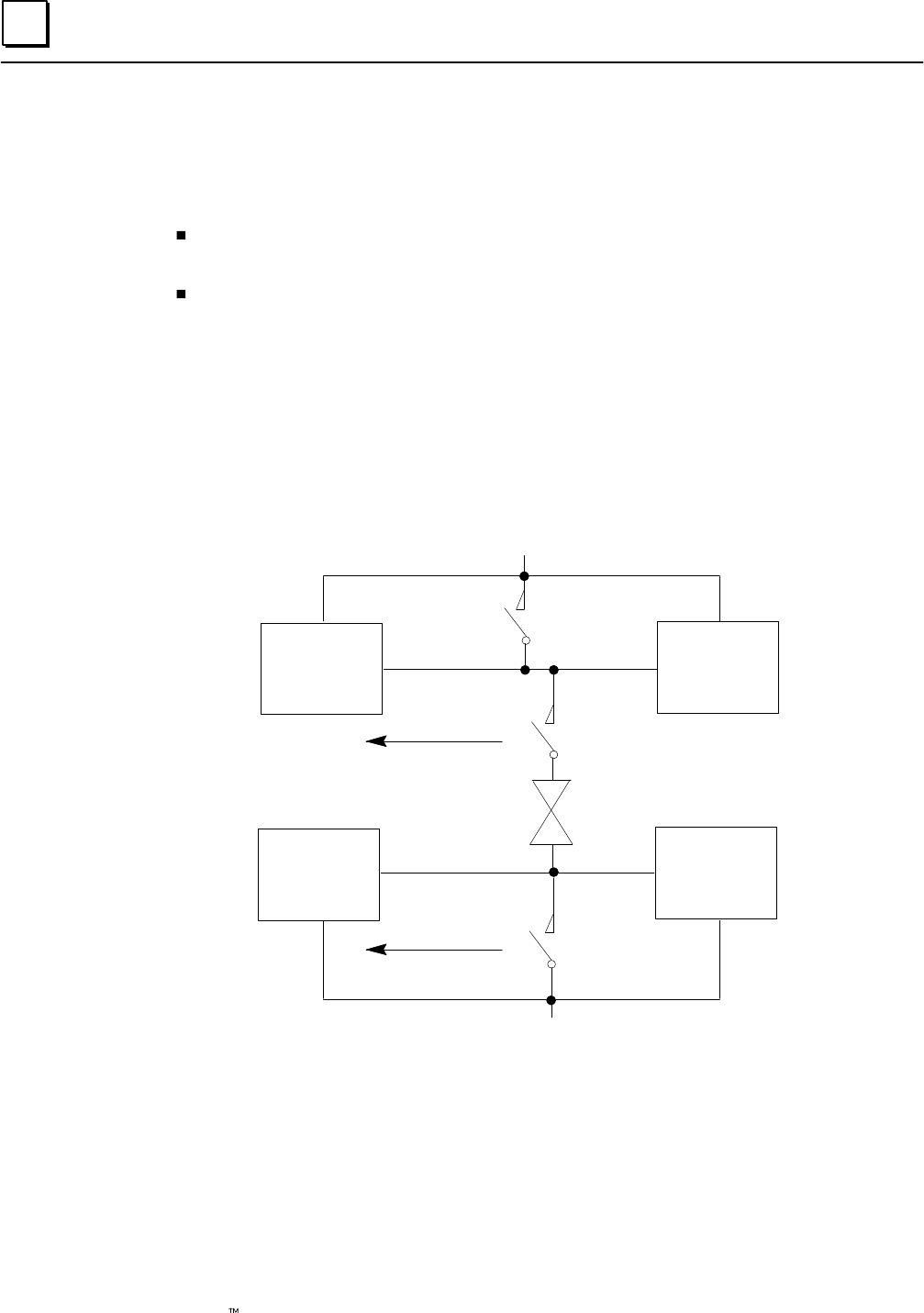
Manual and in the Genius Discrete and Analog Blocks User’s Manual.
If an individual block is configured for Hot Standby redundancy mode, it can be included in
the GMR configuration as a Non-voted Discrete Group.
Blocks that are set up for Duplex PLC redundancy or no redundancy are not autotested.
They operate in the same manner as Duplex blocks in a non-GMR system.
GMR Mode
Configuring a block for GMR mode changes its operating characteristics as described below.
GMR mode supports non-redundant outputs with or without pulse test, and
redundant outputs with or without output autotest.
To prevent false Failed Switch diagnostics during switching transitions, detection of
Failed Switches is delayed for one second.
For the 16-circuit DC block, detection of No-load faults is delayed for one second.
This prevents No-load faults being falsely reported during switching transitions.
Operation of Block OK LED is modified. For the 16-circuit DC block, the Unit OK
LED does not indicate No-load faults when the block is in GMR mode. This is
necessary, since blocks may share output loads.
Modified fault reporting. In GMR mode, blocks automatically report faults to bus
controllers at serial bus addresses 29, 30, and 31.
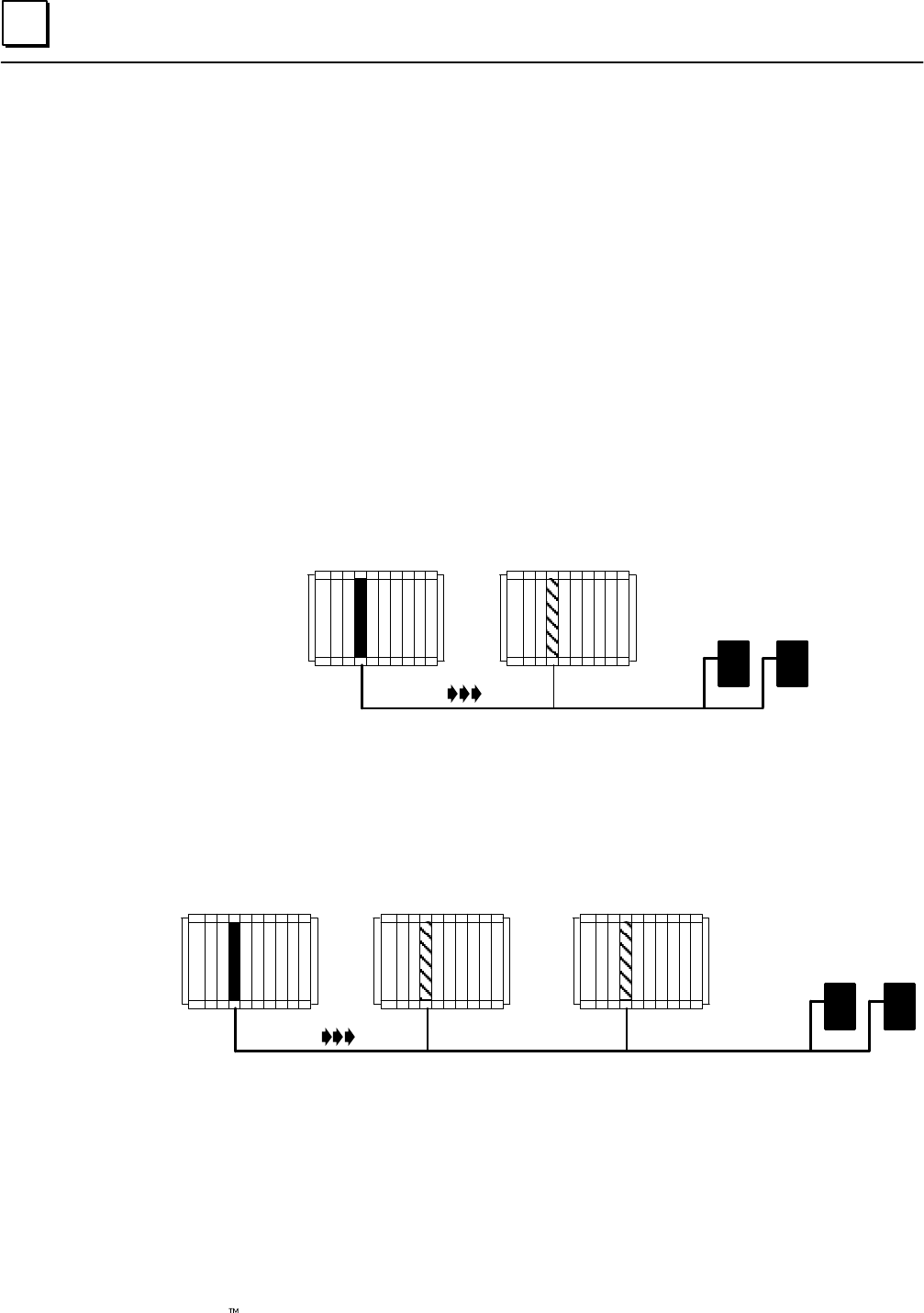
3
3-10 Genius Modular Redundancy Flexible Triple Modular Redundant (TMR) System
User’s Manual – March 1995 GFK-0787B
Hot Standby Mode
Individual blocks can be included in the output subsystem as GMR blocks, Hot Standby
blocks, or non-GMR blocks. There are significant differences in block operation between
these three operating modes.
Operation of GMR output blocks and non-GMR blocks is explained elsewhere in this
chapter. Hot Standby mode is a type of Genius redundancy that can be used with or
without GMR.
Basic Hot Standby Mode Operation
In basic Hot Standby mode (without GMR), blocks receive outputs from two PLCs, but
they are normally controlled directly by the PLC at serial bus address 31. If no output
data is available from bus address 31 for a period of three bus scans, the outputs are
immediately controlled by the PLC at bus address 30. If output data is not available
from either 30 or 31, outputs go to their configured default or hold their last state. The
PLC at bus address 31 always has priority, so that when 31 is online, it always has control
of the outputs.
Bus Controller
31 Bus Controller
30
outputs
Selection of Hot Standby mode is made during block configuration.
Hot Standby Mode in a GMR System
If a block is set up for Hot Standby mode in the GMR configuration, its Hot Standby
operation is automatically expanded to include three PLCs: 31, 30, and 29.
PLC 31 PLC 30
outputs
PLC 29
The manner of operation is the same. The block uses outputs from PLC 31 if they are
available. If not, it uses outputs from PLC 30. If outputs from both PLC 31 and PLC 30
are not available, the block uses outputs from PLC 29. If output data is not available
from any of the three PLCs, outputs go to their configured default or hold their last state.
The PLC at bus address 31 always has priority, so that when 31 is on–line, it always has
control of the outputs.
As mentioned, this assignment of an additional Hot Standby PLC happens automatically
for a Hot Standby block that is included in the GMR configuration.
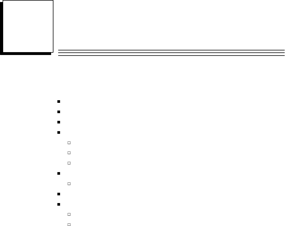
4section level 1 1
figure bi level 1
table_big level 1
4-1
GFK-0787B
Chapter 4PLC Subsystem
This chapter describes operation of the PLC subsystem in a GMR system.
System Startup
CPU Sweep in a GMR System
PLC Operation
Input Processing
Discrepancies
Discrete Inputs
Analog Inputs
Output Processing
Discrete Outputs
I/O Shutdown
Communications Between PLCs
Global Data Redundancy
Entering, Clearing, or Setting Global Data

4
4-2 Genius Modular Redundancy Flexible Triple Modular Redundant (TMR) System
User’s Manual – March 1995 GFK-0787B
System Startup
The following actions occur during orderly startup of the GMR system:
1. Each PLC disables its outputs to Genius blocks. If the Outputs Disable function does
not complete successfully, the GMR software sets the flag “GMR System
Initialization Fault” and the GMR software puts the PLC in Halt mode.
2. Each PLC determines its PLC identity: PLC A, PLC B, or PLC C.
For a PLC, all bus controllers that have been included in the GMR software configuration
must have been assigned the same serial bus address: 29, 30, or 31. Each PLC checks its
GMR configuration to be sure this has been done. If it has, the PLC determines its
identity as follows:
PLC A all GMR bus controllers at serial bus address 31.
PLC B all GMR bus controllers at serial bus address 30.
PLC C all GMR bus controllers at serial bus address 29.
If a PLC determines that its GMR bus controllers have been configured with
differing serial bus addresses, or with addresses outside the range 29–31, it logs an
“Invalid Bus Address” fault into its PLC Fault Table and stops the PLC.
3. Each PLC checks the online status of the other PLCs. “Online” means the other PLC
is running its application program, and its outputs are enabled.
4. Each PLC compares its initial program checksum with those of the other PLCs. If
they do not match, the PLC may (as configured) either stop or keep running. The
next table compares the effects of checksum mismatches with the PLC configured to
allow or reject online program changes:
5. Each PLC compares its initial GMR configuration checksum with those of the other
PLCs. If they do not match, the PLC stops.
After successful initialization, when the application program is running, the PLC will
continuously compare its program checksum against the initial program checksum,
and if they do not match, the PLC will (as configured) either stop or keep running.
Note that if a synchronizing PLC detects that an online PLC has gone offline during
synchronization, it attempts to restart data synchronization with the other PLC. If
the other PLC is not online, the synchronizing PLC will flag that synchronization is
not possible, and halt.
6. PLC C (which uses serial bus address 29) sends an “Assign Controller” datagram to
all blocks and also sends an “Assign Monitor” datagram to the blocks configured for
Hot Standby mode to ensure correct operation with three PLCs. If this function does
not complete successfully, the GMR software places a “GMR System Initialization”
fault into the PLC Fault Table. This fault can be configured to stop initialization and
halt the PLC or allow it to continue.
7. (PLC B or PLC C) initializes data values. This is described in more detail on page 4-4.
8. The Inhibit bit is released, allowing the PLCs to start executing the application program.
9. When the Continue control flag is set by the user’s application program, the PLC
begins sending outputs computed by the application program to Genius blocks.
10. If these outputs match the current output states of the blocks, they are accepted by
the blocks. If a block detects that outputs from a PLC do not match the current
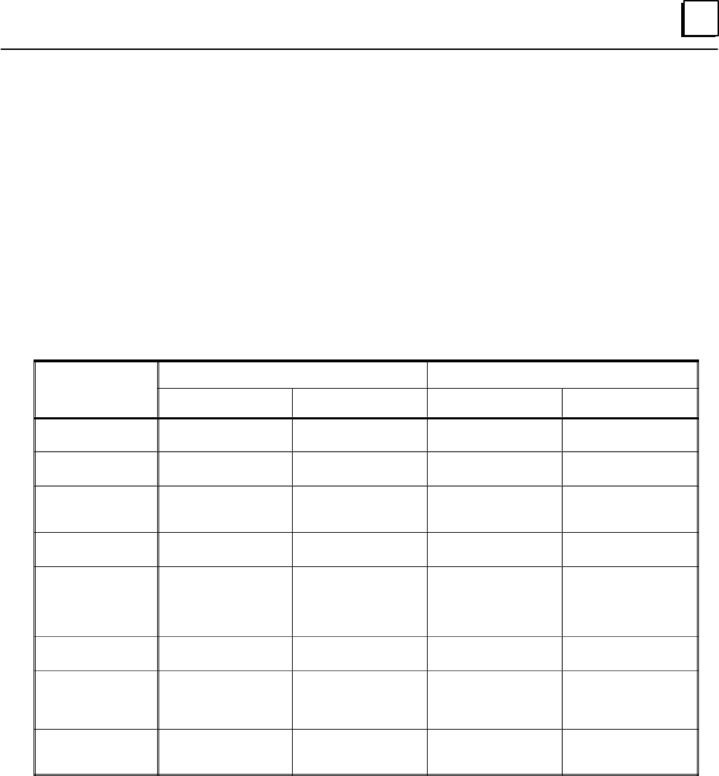
4
4-3GFK-0787B Chapter 4 PLC Subsystem
output states of the blocks, the block does not use those outputs in its output voting.
The block(s) continue to ignore outputs from the PLC until they match those of the
block’s voted outputs or until commanded to do so by setting the FORCLOG
command bit (%M12263). This is covered on more detail on page 7-17.
Startup requires multiple PLC sweeps to complete. Execution of the application program
should not be started until initialization and synchronization have been completed
successfully.
Online Changes
The GMR configuration can be set up to either permit or reject online program changes.
These changes result in checksum mismatches. Such mismatches are handled as
described below by the PLCs in the system.
Type of Mismatch
or Change
Configured to Allow Changes Configured to Reject Changes
or Change
Detected Changed/Started PLC Other PLC(s) Changed/Started PLC Other PLC(s)
Program Checksum
mismatch at startup “Program Mismatch”
message logged “Program Mismatch”
message logged “Program Mismatch” mes-
sage logged. PLC stopped No Action
( Following PLC Fault
Reset) “Program Mismatch”
message re-logged “Program Mismatch”
message re-logged N/A – PLC is stopped No Action
Program Checksum
change while running “Program Change” mes-
sage logged “Program Changed” mes-
sage logged “Program Changed” mes-
sage logged
PLC stopped
No Action
( Following PLC Fault
Reset) “Program Mismatch”
message logged “Program Mismatch”
message logged N/A – PLC is stopped No Action
GMR Configuration
Checksum mismatch
at startup
“GMR Configuration
Mismatch” and “Pro-
gram Mismatch” mes-
sages logged. PLC
stopped
No Action “GMR Configuration
Mismatch” and “Program
Mismatch” messages
logged. PLC stopped
No Action
( Following PLC Fault
Reset) N/A – PLC is stopped. No Action N/A – PLC is stopped No Action
Configuration Check-
sum mismatch while
running
“GMR Configuration
Changed” and “Program
Changed” messages
logged.
“GMR Configuration
Changed” and “Program
Changed” messages
logged.
“GMR Configuration
Change” and “Program
Changed” messages
logged. PLC stopped
No Action
( Following PLC Fault
Reset) “GMR Configuration
Mismatch” message
logged.
“GMR Configuration
Mismatch” message
logged
N/A – PLC is stopped No Action
In all cases, a fault message is logged into the PLC Fault Table.
If the fault condition remains after the PLC Fault is reset, the message is relogged. The
message indicates which PLC has changed, or which mismatches.
A change to the GMR Configuration information takes effect only when the PLC is
transitioned from Stop to Run mode. Therefore, the PLC should be placed in Stop mode
before downloading a new GMR Configuration.
Autotesting is suspended if a PLC is started up with a new configuration. After all PLCs
have been given the same configuration, autotesting will resume.

4
4-4 Genius Modular Redundancy Flexible Triple Modular Redundant (TMR) System
User’s Manual – March 1995 GFK-0787B
Data Initialization
During startup, a PLC either sets a flag to notify the application program to initialize %R
and %M memory, or synchronizes the data with corresponding data in the other PLC(s).
The %M data is typically latch logic states, while the %R data is typically timer/counter
data. The beginning addresses and lengths of both areas are set up during configuration.
If both the other PLCs are offline (application programs not running and not
sending output data), the initializing PLC sets a (cold start) flag to the application
program, which can initialize the selected memory areas (%R and %M) as
appropriate.
If either or both of the other PLCs is already online (running the application
program and transmitting output data), the initializing PLC synchronizes the %M
and %R data with that of the other PLC(s).
1. The initializing PLC first reads %R then %M data from the online PLC with the
higher bus controller serial bus address (31 takes precedence over 30, 30 over
29). Data is read in ascending order.
The PLC reads data only once. If data in the online PLC changes after the
initializing PLC reads it, the change is not noticed. To minimize data differences
on continually changing data such as timer and counter accumulators, they
should be located at the end (top) of the %R area (because it is read last).
2. After reading all of the selected %R and %M data from the first online PLC, the
initializing PLC then reads %M data from the other online PLC. It places this
data into a configurable area of %R memory.
3. After reading the %M data from both online PLCs, the initializing PLC compares
the data. If the data does not match, it tries again. After a total of three retries, if
the data still does not match, the PLC may either:
( ) Halt the PLC (if this fault is configured as fatal)
( ) Allow the PLC to continue operating (if it is configured as diagnostic)
and set the appropriate %M status flag.
%M12232 Init Miscompare at startup
%M12234 System fault at startup
The action taken is determined by the GMR configuration (see page 6-22).
4. It may take several CPU sweeps to read all the data from both PLCs. Data is read
in quantities of up to 64 words at a time. The data transfer is divided across the
busses to minimize the total time required. Therefore the overall time depends
on the data lengths and the number of busses available.
5. If the initializing PLC is unable to successfully read all the data from the other
PLC(s), it sets a flag “Synchronization hardware failure” for the application
program. The entire synchronization sequence then begins again, excluding the
Genius bus with which communications failed.
During GMR configuration, the PLC can be configured to either stop or continue in
the event of synchronization failure.
After successful synchronization, the PLC clears a flag “Inhibit User Application”.
This must be used in the application program to prevent execution of the program
until it has been cleared.
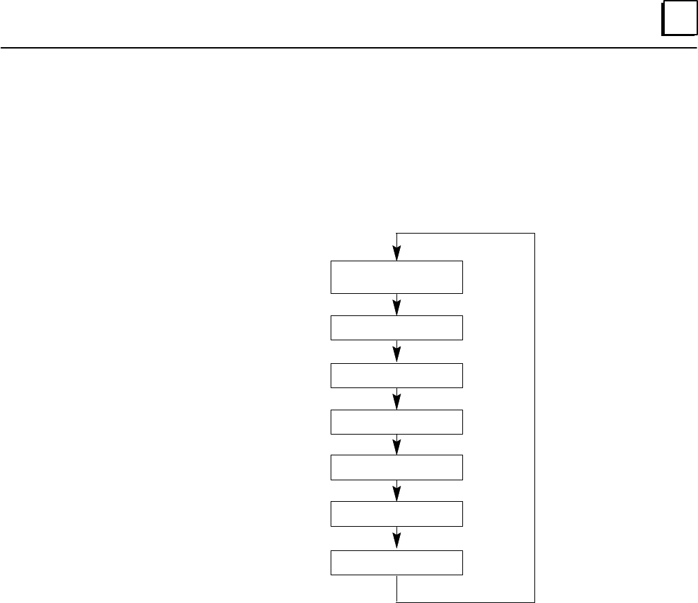
4
4-5GFK-0787B Chapter 4 PLC Subsystem
CPU Sweep in a GMR System
The special functions required for Genius Modular Redundancy include autotest, input
voting, and alarming. These GMR functions are provided by a set of Program Blocks that
are placed into the Program Folder using the LM90 librarian feature. After this is done,
the GMR logic is executed automatically by the CPU as shown below.
Start of Sweep
Housekeeping
Input Scan
GMR functions
Application Program
GMR functions
Output Scan
Additional CPU Tasks
PLC Operation
Each PLC in the GMR system receives the input state from each connected block on each
PLC sweep.
The GMR software performs any input voting required for both discrete and analog
inputs and provides voted input data to the PLC. It notes any data discrepancies and
provides fault bits and fault messages that can be accessed by application program.
As always, the application program determines the required state of the outputs as a
function of the inputs received. The application program sets a single output bit for each
device to be controlled. The appropriate number of redundant Genius blocks are
configured to identical output references.
The CPUs monitor the voted output state computed by each Genius output block group
and provide diagnostic information on the detection of any output discrepancy and
identifies the discrepant PLC.
The executive path in each processor (field input to field output) is independent of any
inter-processor data exchange, with the exception of initialization data at powerup.

4
4-6 Genius Modular Redundancy Flexible Triple Modular Redundant (TMR) System
User’s Manual – March 1995 GFK-0787B
Estimating CPU Sweep Time
The GMR system software runs on Series 90-70 CPU788 or CPU789 PLCs. It produces a
“base” CPU sweep time that becomes a part of the overall sweep time of the CPU with a
ladder logic application program in it. This base sweep time should be taken into
consideration during the application program design and development.
Base sweep time depends on GMR configuration parameters such as Input and Output
table sizes. Typical base sweep times for 788 and 789 CPUs are shown below. In this
example, there are six Bus Controllers in each PLC,
with table sizes of with table sizes of
Voted %I = 64 Voted %I = 256
Voted %AI = 64 Voted %AI = 256
Logical %Q = 64 Logical %Q = 256
Base Sweeptime= 79 Milliseconds Base Sweeptime = 88 Milliseconds
The base sweep time for your system could be less or more depending on the table sizes
you configure. Also, base sweep time varies by $10mS during single sweeps when the
GMR system software performs diagnostics on the CPU subsystem and I/O subsystems.
Sweep Time Contribution of Genius I/O and GBCs
The contribution of Genius I/O and Genius Bus Controllers to the sweep time of the PLC
CPU is similar to that of Series 90-70 I/O. There is an overhead for the I/O scan, a per Bus
Controller sweep time impact, a per scan segment sweep time impact; and a transfer
time (per word) sweep time impact for all I/O data.
The potential Bus Controller sweep time impact on the CPU has three parts:
1. Time to open the system communications window, added only once when the first
intelligent option module (such as a Bus Controller) is placed in the system.
2. Time needed to poll each Bus Controller for background messages (datagrams). This
must be added for every Bus Controller in the system.
3. Time needed for the CPU to scan the Bus Controller.
For detailed information about estimating CPU sweep time, refer to the Series 90-70 PLC
Reference Manual (GFK-0265).
Important Note
In the section on Sweep Time Impact, the Series 90-70 PLC Reference
Manual describes the technique of eliminating the first and second parts
of the Bus Controller’s sweep time contribution by closing the system
communications window (setting its time to 0).
This technique should NOT be used in a GMR system.
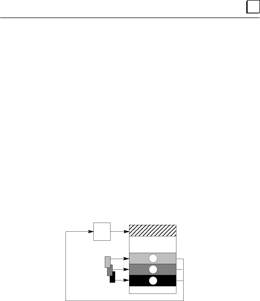
4
4-7GFK-0787B Chapter 4 PLC Subsystem
Input Processing
During the Input Scan portion of the CPU sweep, the PLC receives inputs from the
discrete and analog input blocks. It stores the input data in different areas of memory as
described below.
After the Input Scan, the GMR logic performs voting on the inputs configured for GMR
redundancy, and places the results into the discrete and analog input tables where they
are available to the application program.
Discrepancies
If there is a discrepancy between the original input data for an input and the voted input
state, the GMR software automatically places a message in the I/O Fault Table, where it is
available to the Logicmaster 90 software and the application program logic. Also, fault
bits that report the discrepancy fault for each voted input are available to the application
program, so it can take appropriate action if a discrepancy fault occurs. Discrepancy
faults are latched. Discrepancy reporting is discussed in the chapter on Diagnostics.
Discrete Inputs
During the Input Scan, data from discrete input blocks is placed in the Input Table as
shown below. Inputs from blocks that have been included in the GMR configuration is
placed in the areas labelled A, B, and C. Data from any additional discrete input blocks
(non-voted GMR blocks or blocks on other busses) is placed in a separate area as shown.
Discrete Input Table
Voted Inputs
Non-voted Inputs
Input
Voting
Logic
Bus A inputs A
B
C
Bus B inputs
Bus C inputs
Reserved inputs
The GMR software creates and maintains the separate areas of the discrete Input Table.
In addition to the four areas used for the inputs received from Genius blocks, there are
two additional areas. The first, at the beginning of the Input Table, is for voted inputs.
The other, at the end of the table, is for “reserved” inputs, which are used to inhibit
diagnostics for outputs that are being controlled manually.
The chapter on Programming explains in detail how the Discrete Input table memory is
allocated.
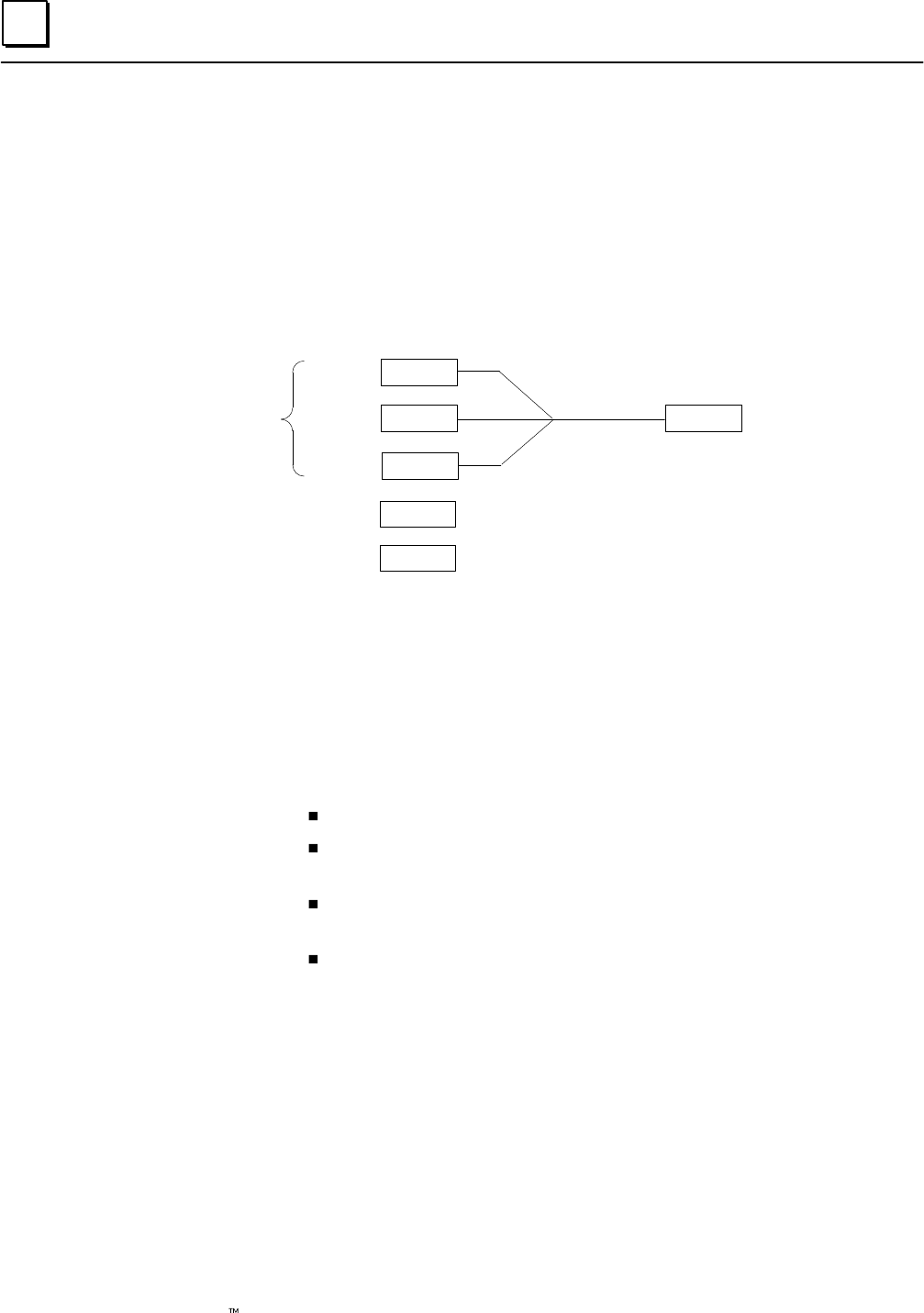
4
4-8 Genius Modular Redundancy Flexible Triple Modular Redundant (TMR) System
User’s Manual – March 1995 GFK-0787B
Discrete Input Voting
Immediately after the input scan, before the application program execution begins, the
GMR software performs input voting. It automatically reads and votes on the three (or
two) sets of data in areas A, B, and C of the discrete Input Table.
If a failure (discrepancy fault, Autotest fault, or Genius fault) occurs, the GMR software
adapts to reject the faulty data. Depending on the configuration of the input group,
input voting may adapt from three inputs to two inputs to one input, or from three
inputs to two inputs to the configured default state.
Field Input
Data
Input A
Input B
Input C
0
1
1
1
Single Input Provided
to Application Logic
Duplex State 1
Default State 0
In addition to field input data, the GMR software may also make use of the input
group’s configured Duplex State and Default State in determining the final input value
to provide to the PLC.
The Duplex State is a “tiebreaker” value used when there are two field
inputs operating. Its operation is described on page 4-10.
The Default State is the value that will be provided directly to the PLC
instead of a voted input value if the following inputs fail:
The single input in a Simplex group.
The remaining input in a Duplex or Triplex group configured for
3–2–1–0 Voting Adaptation.
Either of the two inputs to a Duplex group configured for 3–2–0
Voting Adaptation.
Either of the two remaining inputs to a Triplex group configured for
3–2–0 Voting Adaptation.
Duplex State
Default State
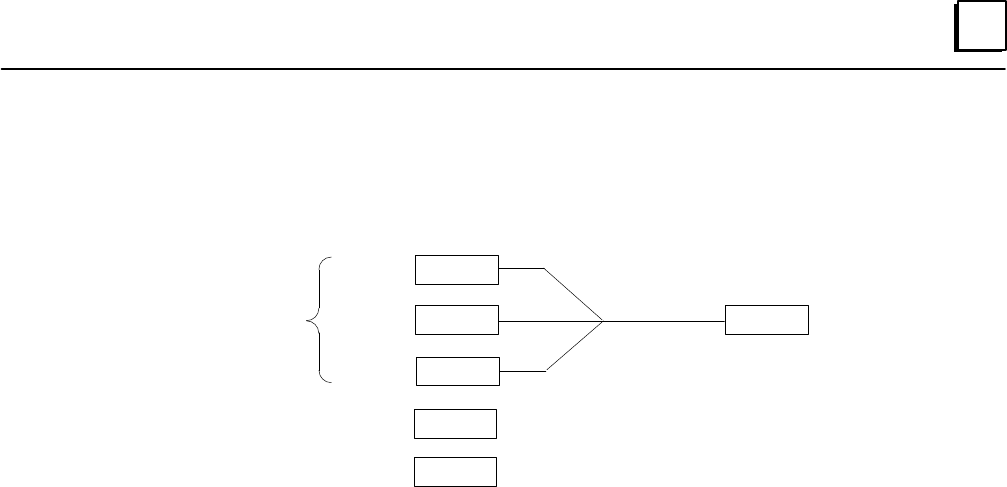
4
4-9GFK-0787B Chapter 4 PLC Subsystem
Voting with Three Discrete Inputs
For a triplex input group with three inputs present, the GMR software performs 2 out of
3 voting.
Field Input
Data
Input A
Input B
Input C
0
1
1GMR Software Performs
2 out of 3 Voting
1
Single Input Provided
to Application Logic
Duplex State 1
Default State 0
The Duplex State and Default State are not used when three field inputs are available.
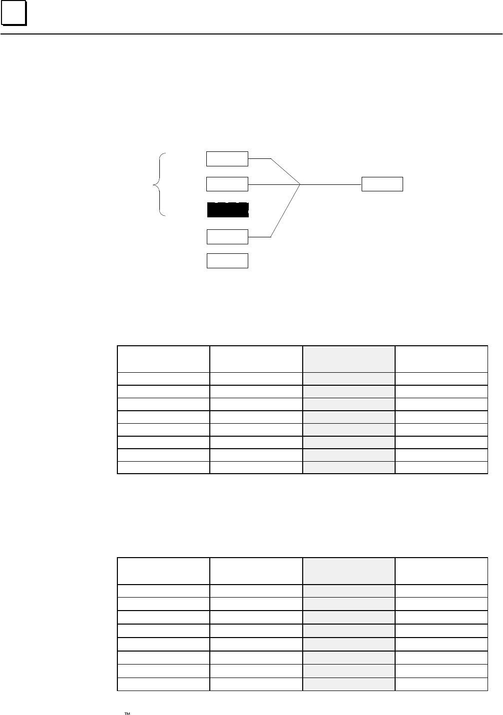
4
4-10 Genius Modular Redundancy Flexible Triple Modular Redundant (TMR) System
User’s Manual – March 1995 GFK-0787B
Voting with Two Discrete Inputs
Two inputs may be present in either a Duplex input group, or in a Triplex input group
where one of the three inputs has failed.
For its 2 out of 3 voting, the GMR software uses the group’s configured Duplex State in
place of a third actual input.
Field Input Data
Input A
Input B
Input C
0
1
1
1
Single Input Provided
to Application Logic
Field Input
Data
Duplex State 1
Default State 0
GMR Software Performs
2 out of 3 Voting
Discrete Input Voting with Two Inputs Present and Duplex State Set to 1
If the Duplex State is set to 1 and two inputs are available, both of the “actual” inputs
must be 0 for the voted input state to be 0. The voted input is 1 if either of the actual
inputs is 1.
Input A State Input B State Input C
(Duplex State) Voted Input State
0 0 1 0
0 0 1 0
0 1 1 1
0 1 1 1
1 0 1 1
1 0 1 1
1 1 1 1
1 1 1 1
Discrete Input Voting with Two Inputs Present and Duplex State Set to 0
If the Duplex Default state is set to 0 and two inputs are available, both of the “actual”
inputs must be 1 for the voted input to be 1. The voted input is 0 if either of the
remaining inputs is 0.
Input A State Input B State Input C
(Duplex State) Voted Input State
0 0 0 0
0 0 0 0
0 1 0 0
0 1 0 0
1 0 0 0
1 0 0 0
1 1 0 1
1 1 0 1
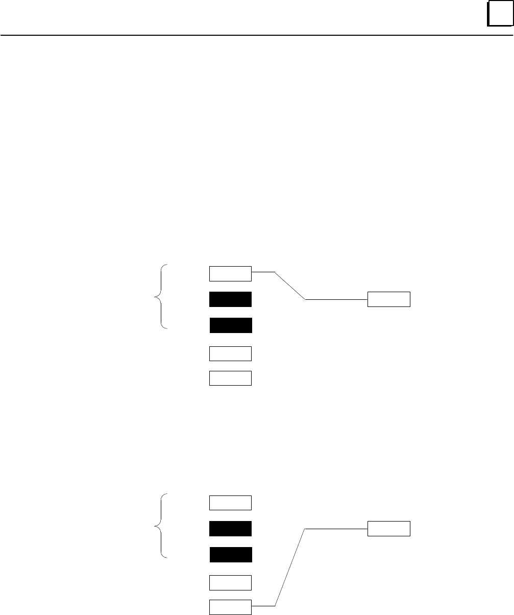
4
4-11GFK-0787B Chapter 4 PLC Subsystem
Voting for One Discrete Input
One input may be present in a non-voted input group, in a Simplex input group, in a
Duplex input group where one input has failed, or in a Triplex input group where two
inputs have failed.
In a non-voted input group, the actual input is always provided to the application logic.
In a voted input group, if only one input is available the result of the voting depends on
the Voting Adaptation mode that has been configured for the input group.
Discrete Input Voting with One Input Present and Voting Adaptation Set to 3–2–1–0
For a Simplex Input group (one input) the voted input is the same as the actual input.
This is also true if there is just one actual input present on a Duplex or Triplex group
configured for 3–2–1–0 Voting Adaptation.
Field Input Data
Input A
Input B
Input C
0
0
1GMR Software Performs
1 out of 1 Voting if Voting
Adaptation is 3–2–1–0
0
Input Provided
to Application
Logic
Duplex State 0
Default State 1
Field Input
Data
Discrete Input Voting with One Input Present and Voting Adaptation Set to 3–2–0
Configuring a Duplex or Triplex input group for 3–2–0 Voting Adaptation prevents the
data from just one input being used as the only input data for that group. If a Duplex or
Triplex group configured for 3–2–0 Voting Adaptation has just one input present, the
configured input Default State is used instead of the remaining actual input.
Field Input Data
Input A
Input B
Input C
0
0
1GMR Software uses Default State
if Voting Adaptation is 3–2–0
1
Input Provided
to Application
Logic
Duplex State 0
Default State 1
Field Input
Data
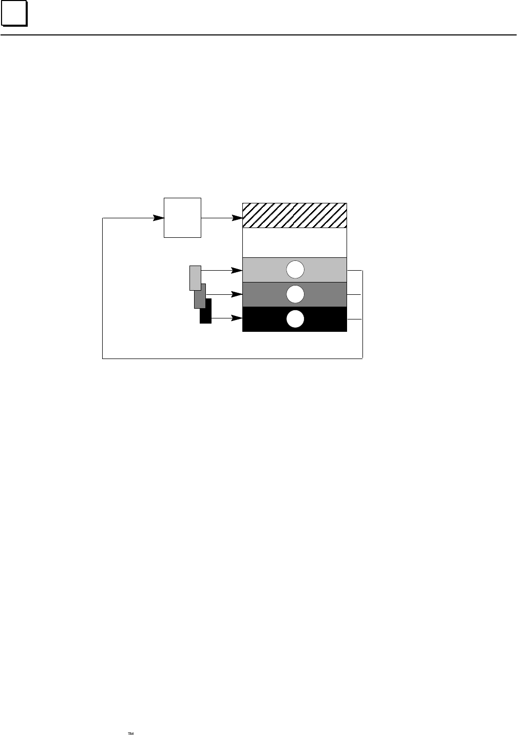
4
4-12 Genius Modular Redundancy Flexible Triple Modular Redundant (TMR) System
User’s Manual – March 1995 GFK-0787B
Analog Inputs
The method of analog input processing is similar to the method used for discrete inputs.
During the Input Scan, data from analog input blocks is placed in the Analog Input Table
as shown below. Inputs from blocks that have been included in the GMR configuration
are placed in the areas labelled A, B, and C. Data from any additional analog input
blocks (non-voted blocks or blocks on other busses) is placed in a separate area as
shown.
Analog Input Table
Voted Inputs
Non-voted Inputs
Input
Voting
Logic
A inputs A
B
C
B inputs
C inputs
The GMR software creates and maintains the separate areas of the analog Input Table. In
addition to the four areas used for the inputs received from Genius blocks, there is an
additional area at the beginning of the analog Input Table for voted inputs.
The chapter on Programming explains in detail how Analog Input table memory is
allocated.
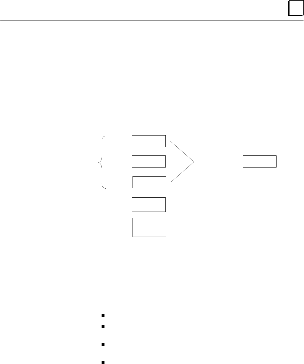
4
4-13GFK-0787B Chapter 4 PLC Subsystem
Analog Input Voting
Immediately after the input scan, before the application program execution begins, the
GMR software performs input voting. It automatically reads and votes on the three sets
of data in areas A, B, and C of the analog Input Table. How it does the voting is
described below. It places the resulting voted input value into the voted inputs area of
the Input Table.
If a failure (discrepancy fault, or Genius fault) occurs, the GMR software rejects the
faulty data. Depending on the configuration of the input group, input voting may go
from three inputs to two inputs to one input, or from three inputs to two inputs to the
configured default value.
Field Input Data
Input 1
Input 2
Input 3
152
150
110
150
Single Input Provided
to Application Logic
Field Input
Data
Duplex State
Default State
low, high,
or average
hold last,
minimum, or
maximum
In addition to field input data, the GMR software may also make use of the input
group’s configured Duplex State and Default State in determining the final input value
to provide to the PLC.
The Duplex State is a “tiebreaker” value that is used when there are two
field inputs present. The Duplex State may be configured as the higher
actual input value, the lower value, or an average of the two.
The Default State is the value that will be provided directly to the PLC
instead of a voted input value if the following inputs fail:
The single input in a Simplex group.
The remaining input in a Duplex or Triplex group configured for
3–2–1–0 Voting Adaptation.
Either of the two inputs to a Duplex group configured for 3–2–0
Voting Adaptation.
Either of the two remaining inputs to a Triplex group configured for
3–2–0 Voting Adaptation.
The Default State can be configured as the last input state, or a specified
maximum or minimum value.
Duplex State
Default State
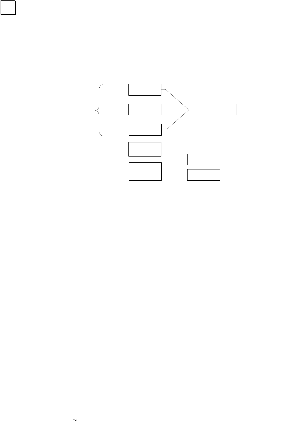
4
4-14 Genius Modular Redundancy Flexible Triple Modular Redundant (TMR) System
User’s Manual – March 1995 GFK-0787B
Voting for Three Analog Inputs
For a triplex input group with three inputs present, the GMR software compares three
corresponding analog input values. It selects the intermediate value and places it into
the voted inputs portion of the Analog Input Table.
Field Input Data
Input 1
Input 2
Input 3
152
150
110
150
Single Input Provided
to Application Logic
Field Input
Data
Duplex State
(low, high, or average value)
Default State
(hold last, minimum, or
maximum)
average
max.
100
175
minimum value
maximum value
The Duplex State and Default State are not used when three field inputs are available.
In the illustration above, inputs A, B, and C might represent the first input channel on
each block in a three-block group. The PLC would place the selected input value into the
first voted input word for that group.
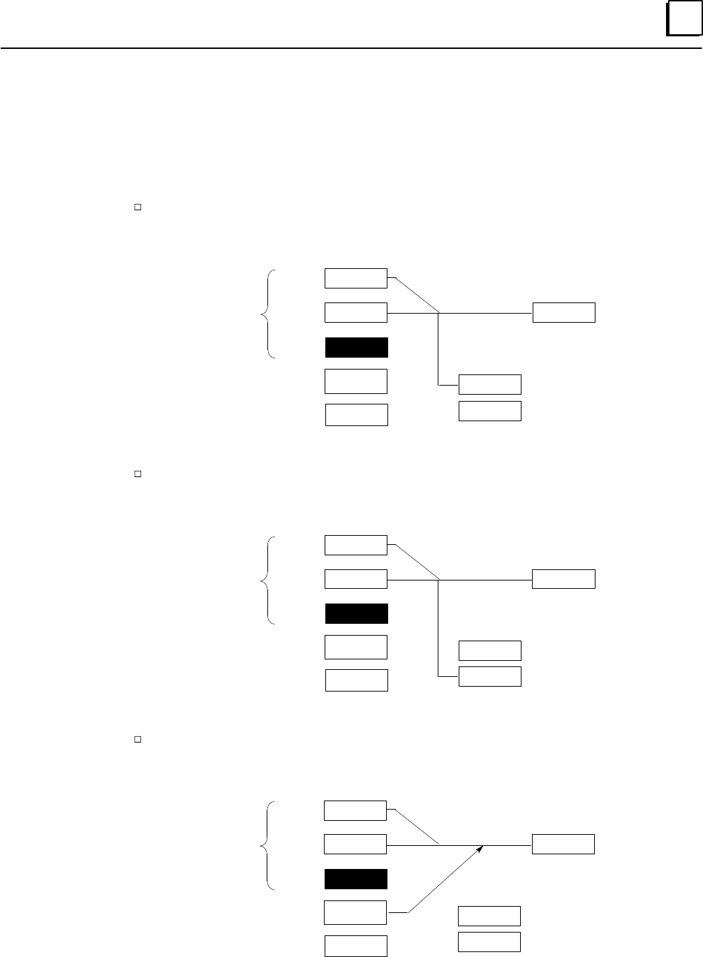
4
4-15GFK-0787B Chapter 4 PLC Subsystem
Voting for Two Analog Inputs
Two inputs may be present in either a Duplex input group, or in a Triplex input group
where one of the three inputs has failed.
Three vote options in duplex mode are determined by the duplex state: highest, lowest,
or average.
If lowest has been configured, the GMR software selects the intermediate value with
the unused (third) channel being assigned its minimum configured value.
Field Input Data
Input 1
Input 2
Input 3
152
150
175
150
Single Input Provided
to Application Logic
Field Input
Data
Duplex State
(low, high, or average value)
Default State (hold last,
minimum, or maximum)
lowest
max.
100
175
minimum value
maximum value
If highest has been configured, the GMR software selects the intermediate value, with
the unused (third) channel being assigned its maximum configured value.
Field Input Data
Input 1
Input 2
Input 3
152
150
175
152
Single Input Provided
to Application Logic
Field Input
Data
Duplex State
(low, high, or average value)
Default State (hold last,
minimum, or maximum)
highest
max.
100
175
minimum value
maximum value
If average has been configured, the GMR software averages the two remaining
input values and supplies the result to the PLC Input Table.
Field Input Data
Input 1
Input 2
Input 3
152
150
175
151
Single Input Provided
to Application Logic
Field Input
Data
Duplex State
(low, high, or average value)
Default State (hold last,
minimum, or maximum)
average
max.
125
175
minimum value
maximum value
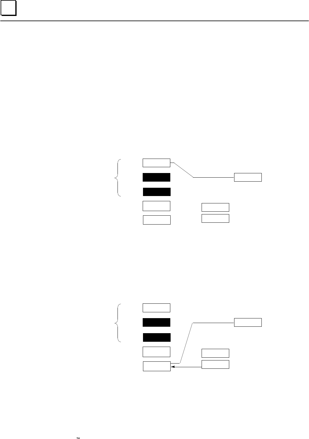
4
4-16 Genius Modular Redundancy Flexible Triple Modular Redundant (TMR) System
User’s Manual – March 1995 GFK-0787B
Voting for One Analog Input
One input may be present in a non-voted input group, in a Simplex input group, in a
Duplex input group where one input has failed, or in a Triplex input group where two
inputs have failed.
In a non-voted input group, the actual input is always provided to the application logic.
In a voted input group, if only one input is available the result of the voting depends on
the Voting Adaptation mode that has been configured for the input group.
Discrete Input Voting with One Input Present and Voting Adaptation Set to 3–2–1–0
For a Simplex Input group (one input) the voted input is the same as the actual input.
This is also true if there is just one actual input present on a Duplex or Triplex group
configured for 3–2–1–0 Voting Adaptation.
Field Input Data
Input 1
Input 2
Input 3
152
150
175
152
Single Input Provided
to Application Logic
Field Input
Data
Duplex State
(low, high, or average value)
Default State (hold last,
minimum, or maximum)
lowest
max.
100
175
minimum value
maximum value
GMR Software Performs
1 out of 1 Voting if Voting Adapta-
tion is 3–2–1–0
Discrete Input Voting with One Input Present and Voting Adaptation Set to 3–2–0
Configuring a Duplex or Triplex input group for 3–2–0 Voting Adaptation prevents the
data from just one input being used as the only input data for that group. If a Duplex or
Triplex group configured for 3–2–0 Voting Adaptation has just one input present, the
configured input Default State is used instead of the remaining actual input.
Field Input Data
Input 1
Input 2
Input 3
152
150
175
175
Single Input Provided
to Application Logic
Field Input
Data
Duplex State
(low, high, or average value)
Default State (hold last,
minimum, or maximum)
lowest
max.
100
175
minimum value
maximum value
GMR Software Performs
1 out of 1 Voting if Voting Adapta-
tion is 3–2–1–0
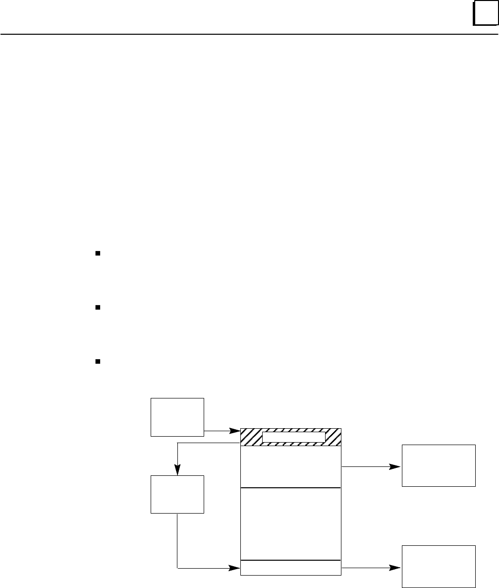
4
4-17GFK-0787B Chapter 4 PLC Subsystem
Output Processing
For outputs, the PLC does not perform “redundancy” voting. Instead, voting is done by
the specified types of discrete output block groups. Analog blocks do not provide
redundancy voting or autotest features. Both discrete and analog Genius blocks can be
used in the output subsystem as non-GMR blocks, however.
Discrete Outputs
As it does for inputs, the GMR software uses separate areas of the Output Table for non-voted
outputs, fault-tolerant outputs and copies of the fault-tolerant outputs.
After the application program executes, the GMR software processes discrete output
data as described below.
The application program places outputs into the discrete Output Table. Data for blocks
that are included in the GMR configuration is placed at the start of the output table. In
the illustration below, the application program outputs for redundant blocks are labelled
“logic outputs”. This data is followed by outputs for non-voted blocks.
The GMR software copies these logic output into the bottom portion of the Output Table.
This data, shown as Fault-tolerant Outputs in the illustration below, is used for physical
outputs for the blocks. This separation of physical outputs from logical outputs prevents
disruption of outputs such as latches and seal circuits during autotesting.
During the output scan portion of the CPU sweep, the CPU sends the non-voted outputs
plus the copied fault-tolerant outputs to the Genius blocks.
Discrete Output Table
Logic Outputs
Available for
Simplex Outputs
Fault-tolerant Outputs
Reserved memory
GMR
Logic
Application
Program
Fault-tolerant
Output
Devices
Non-voted
Outputs
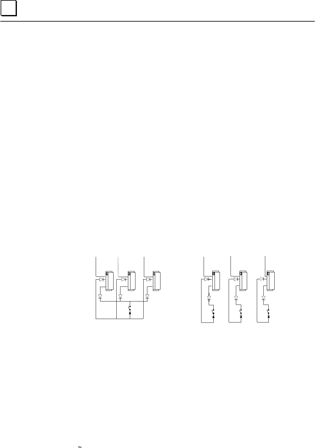
4
4-18 Genius Modular Redundancy Flexible Triple Modular Redundant (TMR) System
User’s Manual – March 1995 GFK-0787B
I/O Shutdown
When the GMR system diagnoses a discrete I/O fault, it logs the appropriate faults in its
fault tables and set the appropriate fault contacts. For certain types of discrete I/O faults,
the system optionally allows a predefined amount of time for the problem that caused
the fault to be repaired. If the problem is not rectified within this period of time, an I/O
Shutdown of the I/O corresponding to the affected block(s) occurs. I/O shut down can
be completely disabled and prevented by turning on the Cancel I/O Shutdown control
bit (%M12265).
I/O Shutdown is defined as setting the affected I/O to its safe state. For outputs, this is
the Off state. For discrete inputs, the shutdown state is the “default” state for an input
group in the GMR configuration. This can be selected on an input group basis.
Synchronous or Asynchronous Input Autotest and I/O Shutdown
In the GMR configuration discrete input groups can be configured for either
Synchronous or Asynchronous input autotesting.
If redundant discrete input devices are used, which allows the individual blocks in a
group to stay isolated from each other (I.E. the power feed outputs (point 16) of each
block ARE NOT wired together), asynchronous input autotesting can be selected.
Asynchronous input autotesting can also be selected if non-redundant simplex discrete
input devices are used with isolation between blocks. Using this option allows the input
autotest to continue executing on other blocks in a group which are not affected by the
fault. Because input autotesting continues in this case, an I/O shutdown is not necessary
and WILL NOT occur. (See Chapter 8 – installation information)
Blocks Wired Together Blocks Not Wired Together
If non–redundant simplex discrete input devices are used without isolation between
blocks (I.E. the power feed outputs (point 16) of each block ARE wired together), then
synchronous input autotesting must be selected in the GMR configuration for the input
group. (See Chapter 8 – installation information)
For this configuration there are two types of faults which may prevent the autotest from
continuing to execute for that input block group and thus cause a I/O shut down for the
inputs in the group:
1.) Loss of a block within the group. (I.E. any failure which causes the block to no
longer communicate on the Genius Bus such as loss of power.)
2.) Autotest failure of the power feed output (point Q16) of any of the blocks in a group.

4
4-19GFK-0787B Chapter 4 PLC Subsystem
Output Faults that Cause I/O Shutdown
For discrete output groups there are also two types of faults which may prevent the
output autotest from continuing to execute for that output group and thus cause an I/O
shut down for the outputs in the group.
1.) Loss of a block within the group. (I.E. any failure which causes the block to no
longer communicate on the Genius bus such as loss of power.)
2.) Output autotest failure detected of a type which could potentially prevent a
normally energized output from being tripped off. An example is the short of a
source block output to +24 Vdc.
Programming for I/O Shutdown
To be made aware of a pending I/O Shutdown, the program can monitor this GMR
Status Bit:
%M12244 – (IO_SD) Any I/O Shutdown Timer Activated
To completely prevent an I/O Shutdown from occurring, the program can set this GMR
Control Bit:
%M12265 – (SD_CAN) Cancel I/O Shutdown
Interval Until Shutdown in Each PLC
The period of time before an I/O Shutdown occurs depends on the autotest interval
which is set for the system. The initial autotest interval is set by the autotest interval
value selected in the GMR configuration.
The configured autotest interval can be adjusted in each CPU through the application
program by varying the value in the autotest interval register. The system allows for a
total maximum time of 24 hours between a fault occurring and the resultant I/O shut
down when the autotest interval is set to 8 hours.
Examples
The first example shows the I/O Shutdown sequence when the autotest interval is 3
hours.
0
Hours
A B C D
13 11 24
F
614
H
9
EG
10 13
A.) A fault occurs just after the autotest interval at PLCA begins.
B.) PLCA executes the autotest and detects the fault, then starts the 8 hour shutdown
timer. The message “Shut down in 8 hours” is logged in the fault table. The “I/O
Shut Down in Progress” status bit (%M12244) is set in each PLC. The autotest
master function passes to PLCB.
C.) PLCB executes the autotest and detects the fault, then starts its 8 hour shutdown
timer. The message “Shut down in 8 hours” is logged in the fault table. The autotest
master function passes to PLCC.
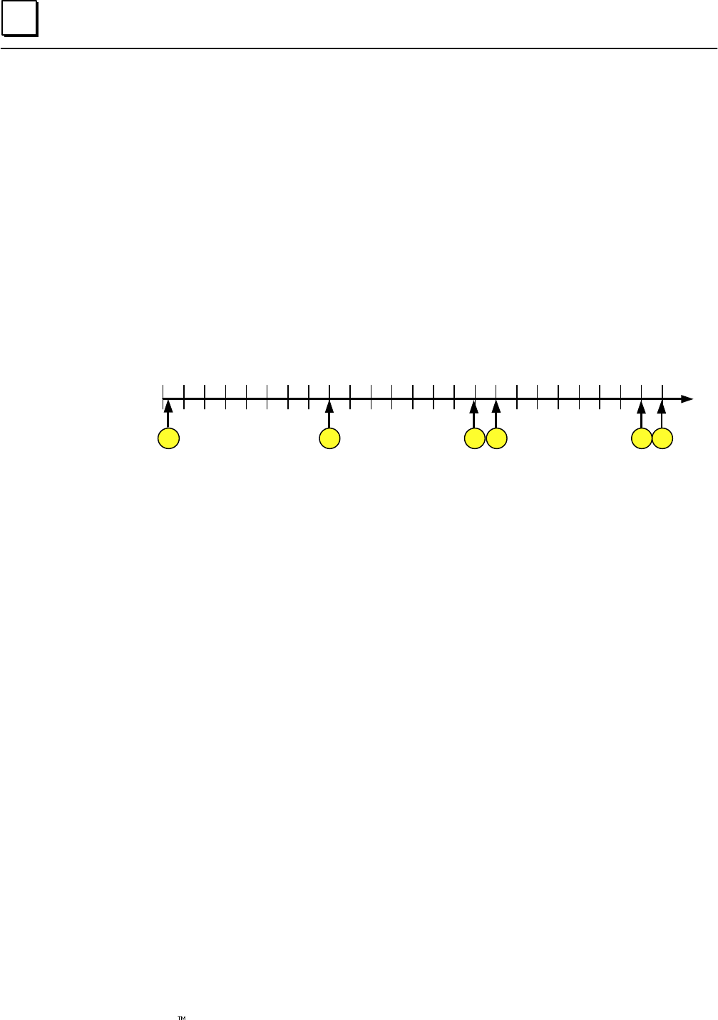
4
4-20 Genius Modular Redundancy Flexible Triple Modular Redundant (TMR) System
User’s Manual – March 1995 GFK-0787B
D). PLCC executes the autotest and detects the fault, then starts its 8-hour shutdown
timer. The message “Shut down in 8 hours” is logged in the fault table. The autotest
master function passes to PLCA.
E.) The message “Shut down in 1 hour” is logged at PLCA.
F.) The shutdown timer expires in PLCA. The message “I/O Shut Down” is logged in
fault table of PLCA. PLCA shuts down the I/O of the affected I/O group. Real I/O is
not yet affected because of the 2 out of 3 voting mechanism, although output
discrepancy errors may be generated.
G.) The message “Shut down in 1 hour” is logged at PLCB.
H.) The shutdown timer expires in PLCB. The message “I/O Shut Down” is logged in
fault table of PLCB. PLCB shuts down the I/O of the affected I/O group. Real I/O IS
NOW affected because of the 2 out of 3 voting mechanism.
This example shows the I/O Shutdown sequence when the autotest interval is 8 hours.
0
Hours
A B C D
124
F
16
9
E
15 23
A.) A fault occurs just after the autotest interval at PLCA begins.
B.) PLCA executes the autotest and detects the fault, then starts the 8 hour shutdown
timer. The message “Shut down in 8 hours” is logged in the fault table. The “I/O
Shut Down in Progress” status bit (%M12244) is set in each PLC. The autotest
master function passes to PLCB.
C.) The message “Shut down in 1 hour” is logged at PLCA.
D.) The shutdown timer expires in PLCA. PLCA shuts down the I/O of the affected I/O
group. The message “I/O Shut Down” is logged in fault table of PLCA. Real I/O is
not yet affected because of the 2 out of 3 voting mechanism, although output
discrepancy errors may be generated. PLCB executes the autotest and detects the
fault, then starts its 8 hour shutdown timer. The message “Shut down in 8 hours” is
logged in the fault table. The autotest master function passes to PLCC.
E.) The message “Shut down in 1 hour” is logged at PLCB.
F.) The shut down timer expires in PLCB. “I/O Shut Down” message is logged in fault
table of PLCB. PLCB shuts down the I/O of the affected I/O group. Real I/O IS
NOW affected because of the 2 out of 3 voting mechanism.

4
4-21GFK-0787B Chapter 4 PLC Subsystem
I/O Shut Down Prevention
If an I/O fault causes an I/O shutdown to initiate, there is up to 16 hours of time to repair
the fault and put the block(s) back into operation before the shutdown occurs. When
the next autotest occurs on the PLC(s) that started its shutdown timer, that PLC
automatically cancels its I/O shutdown (If the autotest is executed without faults on the
affected block(s) before the actual shut down occurs). This autotest can be one that
occurs automatically as specified by the configured autotest interval, or one that is
initiated manually via the GMR control bit Autotest Manual Initiate (%M12260 –
ATMANIN). To clear any standing faults at the block(s) and in the I/O fault table of the
PLCs, an I/O fault reset should be executed by turning on GMR Control bit %M12258
(IORES). Also note that at any time the Cancel I/O Shutdown (%M12265 – SD_CAN) bit
can be used to prevent the shutdown from occurring.
I/O Shut Down Recovery
If an I/O shutdown is allowed to complete, the affected I/O is set to its safe state.
Recovery from an I/O shutdown is accomplished with the following steps:
1) Repair the fault that caused the I/O shutdown to initiate. This may require simply
replacing a blown fuse which had supplied power to a block, or replacing a
damaged or failed block or repairing field wiring.
2) Initiate an I/O autotest in each of the three PLCs so that the PLC(s) can determine that
the block(s) is repaired and again functioning properly. The autotest has to be executed
at the PLCs which had actually started and expired their shutdown timers. The
autotests can be those that occur automatically as specified by the configured autotest
interval, or initiated manually via the GMR control bit Autotest Manual Initiate
(%M12260 – ATMANIN).
3) In the case of a block being powered off or replaced, a shut down of outputs the
output block(s) may require a force logon to get them to accept output data from the
CPUs. This can be done by using the GMR control bit %M12263 (FORCLOG).
4) To clear any standing faults at the block(s) and in the I/O fault table of the PLCs, an I/O
Fault Reset should be executed by turning on GMR Control bit %M12258 (IORES).
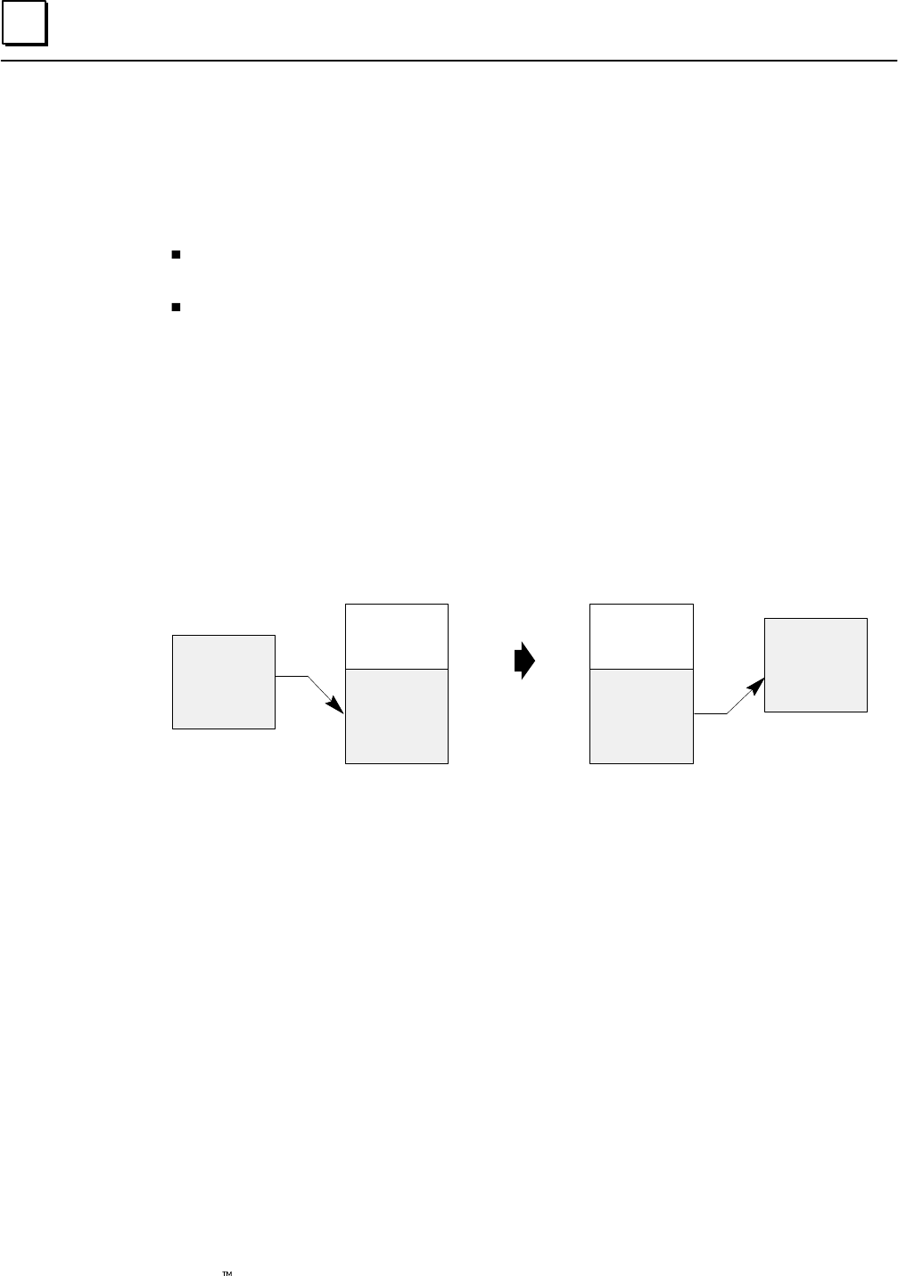
4
4-22 Genius Modular Redundancy Flexible Triple Modular Redundant (TMR) System
User’s Manual – March 1995 GFK-0787B
Communications Between PLCs
Data is transferred between the PLCs in the system using Genius global data. Two busses
are used to transfer duplicate data. While the system is operating, they transfer global
data automatically. This global data includes two types of information:
Application program global data from %G memory. The GMR software
automatically copies this data into %R memory before sending it.
Additional %R data used by the GMR software.
Each scan of the Genius bus, a PLC takes the application program global data it has
copied into %R memory, plus its own additional %R data, and broadcasts it on the bus.
During the same Genius bus scan, when the other PLCs have their turn on the bus, they
send global data in the same way. When a PLC receives Global Data, it copies that
portion of the data that is intended for application program use into %GA, %GB, or
%GC memory (see the Programming chapter for details). The following diagram
summarizes the transfer of GMR global data.
Application
Global
Data
%G
Memory
Application
Global
Data
GMR
Global Data
%R
Memory
Sending PLC
Genius Bus
Application
Global
Data
GMR
Global Data
%R
Memory
Application
Global
Data
%GA, GB. or GC
Memory
Receiving PLCs
Global Data Redundancy
During normal GMR operation, each PLC receives two sets of global data from each of
the other PLCs (one set over each of the two busses mentioned above). The system
defaults to use the data from the first bus (bus a) unless that bus has failed, in which case
the data from the second bus (bus b) will be used). If a PLC loses communications with
another PLC on both busses, the global data from that device is held at its last state. The
GMR software places a fault in the PLC fault table when communications are lost. See
the chapter on Diagnostics for more information.
In addition, the GMR software maintains status flags that can be monitored by the
application program to check the state of communications between PLCs. These are
described in the chapter on Programming.
Entering, Clearing, or Setting Global Data
The application program can read or transmit Global Data as required. Refer to the
Programming chapter for details.
In addition, the application program can use the PLC OK flag to clear or preset the data
as required. This is also described in the Programming chapter.
5section level 1 1
figure bi level 1
table_big level 1
5-1
GFK-0787B
Chapter 5Diagnostics
This chapter describes:
Diagnostics in a GMR System
GMR Autotesting
GMR Discrepancy Reporting
Input Line Fault Detection in a GMR Application
The PLC and I/O Fault Tables in a GMR System
Monitoring Manual Output Controls
Fault and Alarm Contacts
Programming for Diagnostics
The Programming chapter of this book explains some programming considerations for a
GMR application. It includes information about:
Programming for Fault and Alarm contacts
I/O Point Faults
Monitoring the System Status references
Monitoring system forces and overrides
Monitoring the I/O and PLC Fault Tables

5
5-2 Genius Modular Redundancy Flexible Triple Modular Redundant (TMR) System
User’s Manual –March 1995 GFK-0787B
Diagnostics in a GMR System
In a GMR system, extensive diagnostic capabilities are provided by standard Genius I/O
diagnostics and by the special autotesting and discrepancy reporting features of the GMR
software. Standard Genius diagnostics, which are covered in other books, are not described in
detail here.
Each PLC provides a full range of fault table and program access to fault information.
Input Diagnostics
Genius Diagnostics:
Line fault. a feature of the 16-circuit DC blocks. To report line faults, an input must be
configured for tristate operation and installed as explained on page 5-14.
For blocks in GMR mode, a line fault represents a short circuit fault on the field wiring.
For blocks in any other mode, a line fault represents an open circuit fault in the field
wiring.
Autotest Diagnostics. for discrete inputs configured for autotesting., autotesting
determines whether inputs can attain their opposite state (alarm state) and checks for
channel to channel shorts.
Discrepancy Reporting: between the raw input data from each bus and the
corresponding voted inputs.
Output Diagnostics
Genius Diagnostics:
No-load fault: For 16-circuit blocks only, individual outputs can be configured to
enable or disable reporting No-load faults. The minimum load current required
to assure proper no-load reporting is 100mA (not 50mA, as it would be for a
block not used in a GMR group). For an individual block:
If outputs are On with no output load, no-load fault reports may be
generated at any time except during a Pulse Test.
If outputs are Off with no output load, no-load fault reports are generated
during a Pulse Test.
Short circuit fault.
Overtemperature fault.
Overload fault
Failed switch:. Occurs if the actual output state differs from the commanded state.
Autotest Diagnostics. for discrete outputs configured for autotesting. Autotesting
determines whether outputs can attain the opposite of their normal state.
Output Discrepancy Reporting: Blocks configured for GMR mode operation report to
each PLC the discrepancy status for the data from each PLC, together with each
PLC ’s online/offline status.
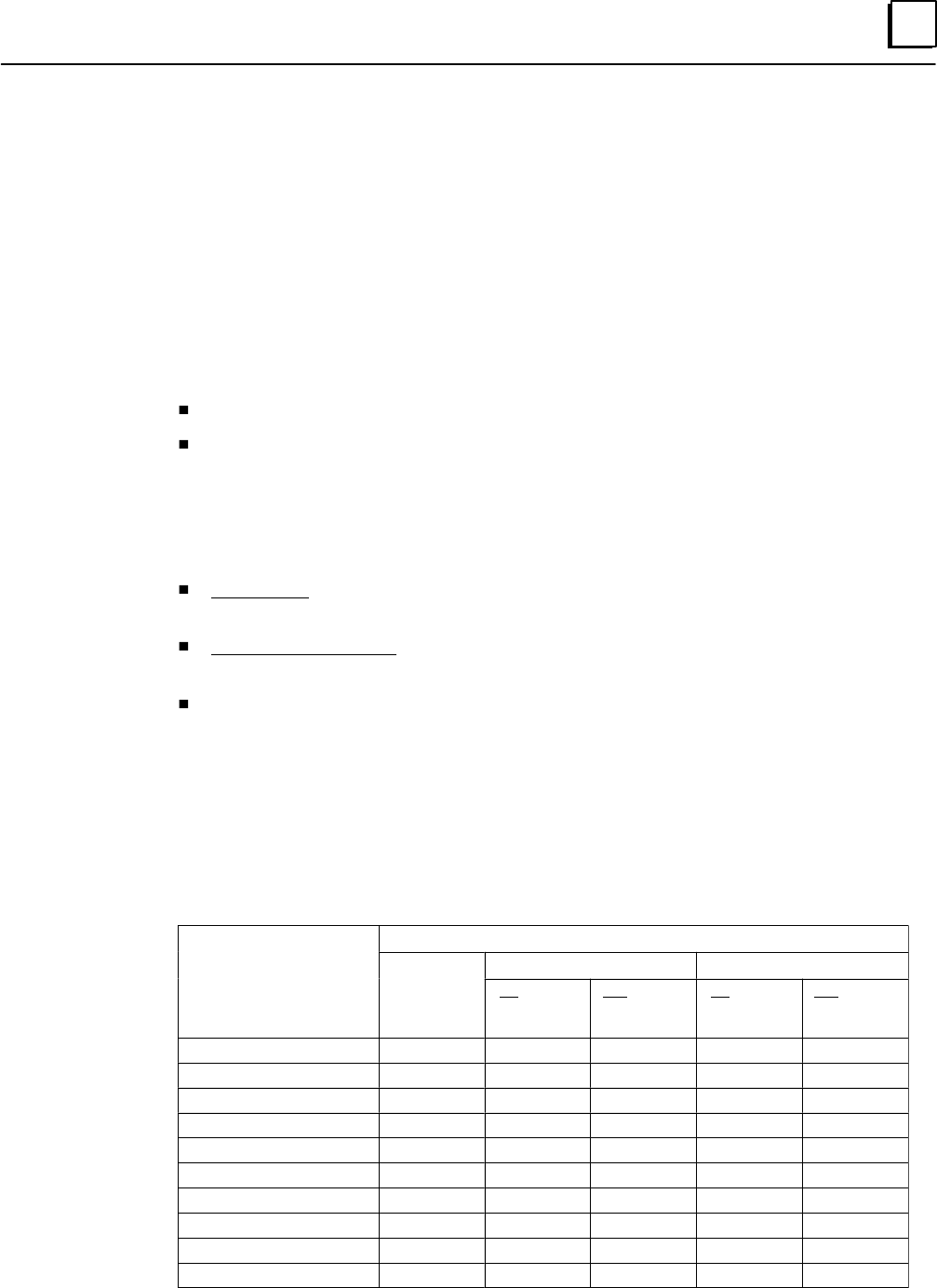
5
5-3GFK-0787B Chapter 5 Diagnostics
Setting Up Blocks to Report Genius Faults
By default, most Genius blocks, including the types of blocks normally used in GMR
systems, send only one copy of a Fault Report. For a GMR system, blocks can be set up to
send additional Fault Reports. The setup needed for a block depends on two things: what
type of block it is, and how many PLCs should receive its Fault Reports..
Setting Up 16- and 32-Circuit DC Blocks to Send Multiple Fault Reports
A 16 or 32 Circuit DC Sink/Source block (only) will send three Fault Reports, one each to
serial bus addresses 29, 30, and 31, if set up in either of the following ways:
For blocks in a GMR group, block configuration is CPU Redundancy = GMR
For non-GMR group blocks, block configuration is CPU Redundancy= Hot Standby.
Hot Standby is selected on “Non-Voted I/O” screen of the GMR configuration software.
Setting Up Other Blocks to Send Multiple Fault Reports
Other blocks may also send “extra” copies of Fault Reports.
Inputs-only blocks automatically send two Fault Reports to serial busses 30 and 31
with no additional configuration.
Output and mixed I/O blocks configured for CPU Redundancy = Hot Standby will
send two Fault Reports to serial bus addresses 30 and 31.
If the block is configured in the GMR configuration, the GMR software issues an
“Assign Monitor” datagram to cause a block to send the third fault report.
Summary Table
The following table summarizes how many Fault Report messages are sent by blocks
configured for different types of CPU Redundancy, with or without the Assign Monitor
datagram. X means the feature is not configurable for that block. (Page 6-50 describes
configuring Genius blocks for Fault Reporting)
CPU Redundancy Mode Configuration
Block Type
GMR
none Hot Standby
Block Type
GMR
no Assign
Monitor
datagram
yes Assign
Monitor
datagram
no Assign
Monitor
datagram
yes Assign
Monitor
datagram
16 or 32 Ckt DC Sink/Src 3 1 2 2 3
8 Ckt AC Grouped I/O X 1 2 2 3
Relay Outputs NO/ NC X 1 2 2 3
16 Ckt AC Inputs X 2 3 X X
4 In, 2 Out Analog X 1 2 2 3
Crnt source Analog In X 2 3 X X
Crnt source Analog Out X 1 2 2 3
Thermocouple or RTD X 2 3 X X
High-speed Counter X 1 2 2 3
PowerTRAC X 1 2 2 3
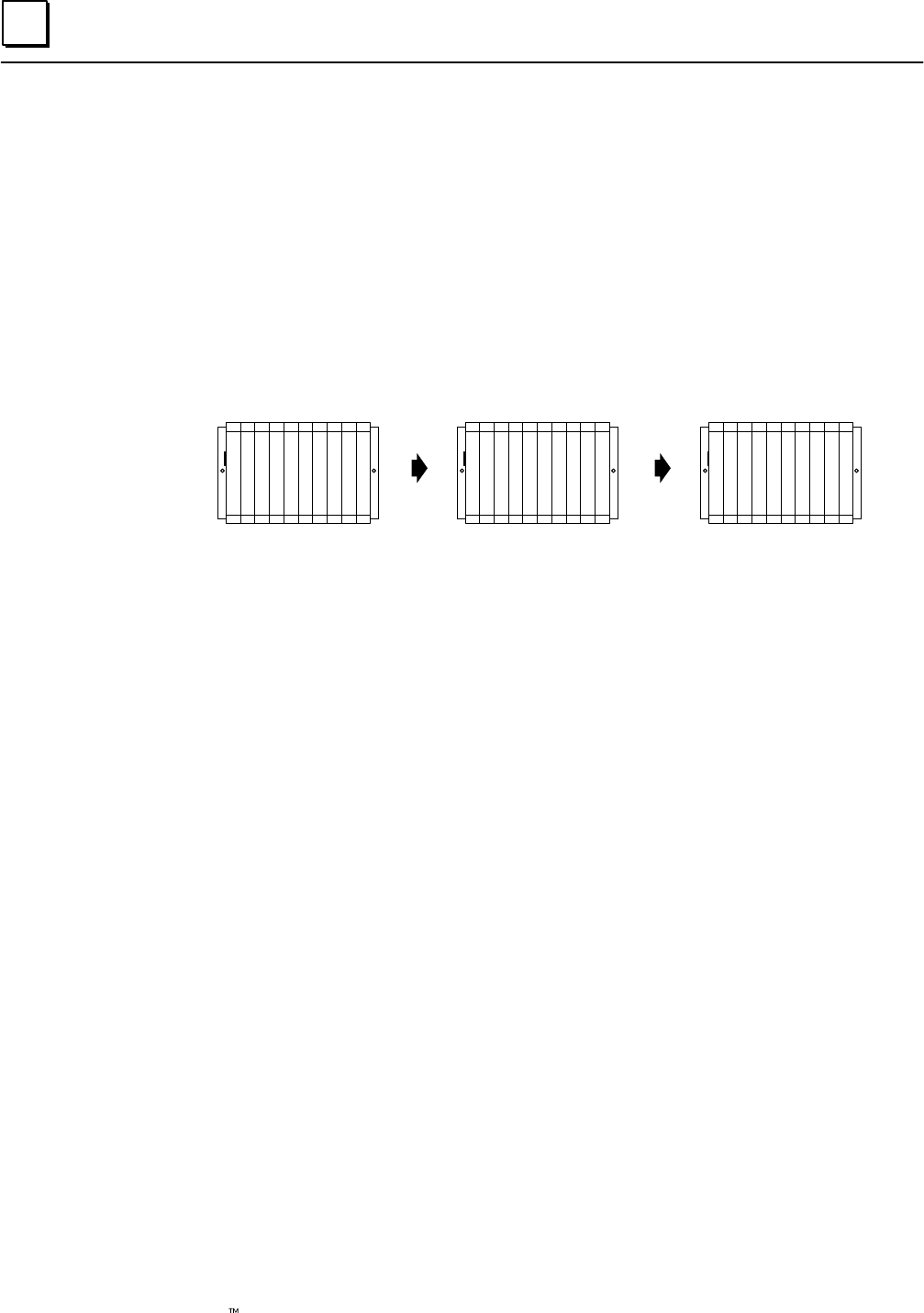
5
5-4 Genius Modular Redundancy Flexible Triple Modular Redundant (TMR) System
User’s Manual –March 1995 GFK-0787B
GMR Autotesting
The GMR software automatically performs autotesting on discrete inputs and outputs that
have been configured to be autotested. Analog inputs and outputs are not autotested by the
GMR software. GMR autotesting can be used in a system with one, two, or three PLCs.
Autotest Sequence
GMR autotesting goes on at the configured interval (0 to 65535 minutes) during system
operation. Each PLC in turn controls the sequence.
PLC A
1. Autotest GMR inputs
2. Complete GMR
output autotest
3. Pass autotest control
to next PLC (here, B).
PLC B
1. Autotest GMR inputs
2. Complete GMR
output autotest
3. Pass autotest control
to next PLC (here, C).
PLC C
1. Autotest GMR inputs
2. Complete GMR
output autotest
3. Pass autotest control
to next PLC (here, A).
If one or two of the PLCs are not available, autotesting continues with the remaining PLC(s).
During its turn as the autotest master, a PLC tests all input and output groups that are set up
for autotesting. These may include the following types of groups:
Input groups: non-voted (1 block)
simplex (1 block)
duplex (2 blocks)
triplex (3 blocks)
Output group: 4-block redundant
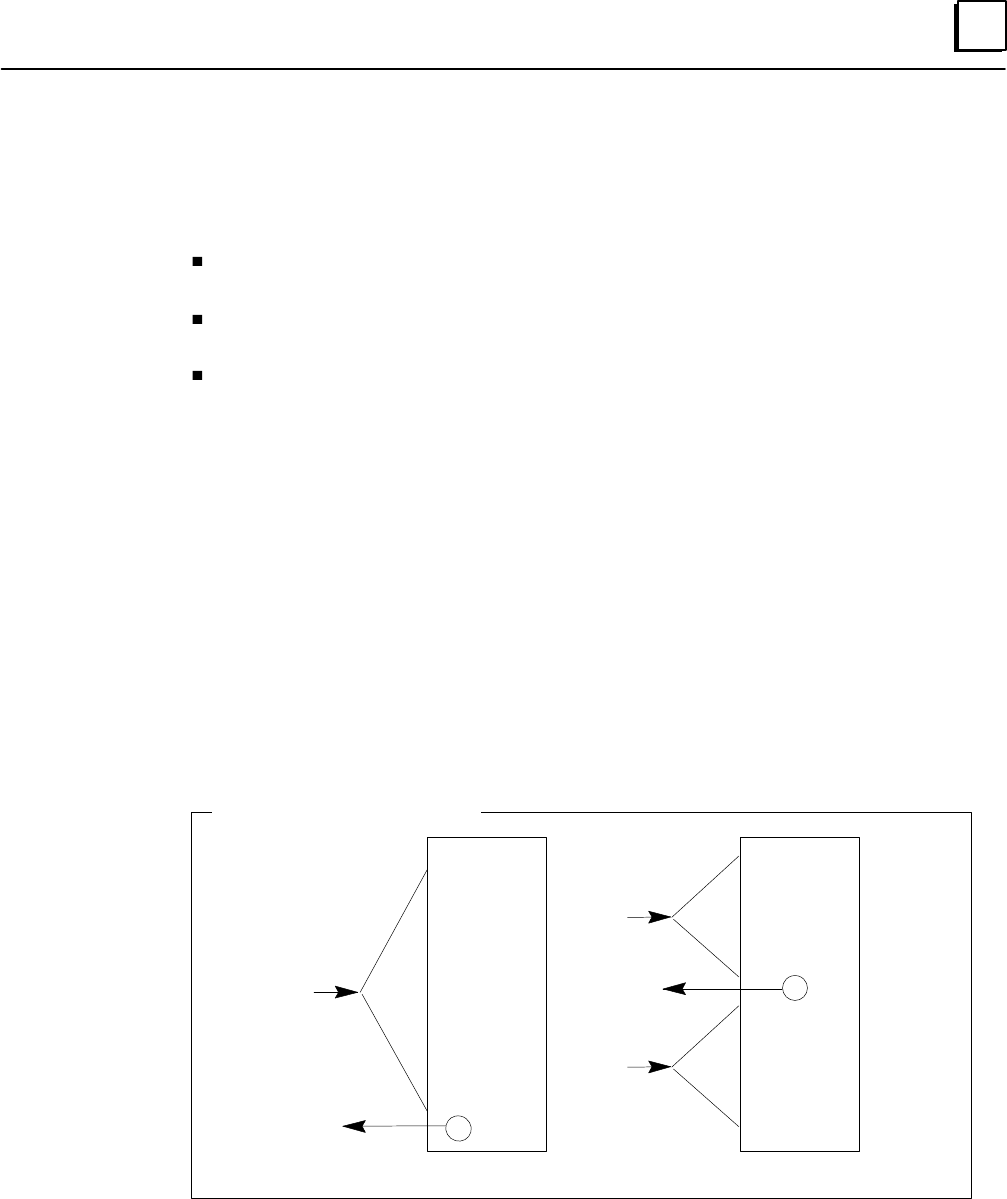
5
5-5GFK-0787B Chapter 5 Diagnostics
Discrete Input Autotest
Discrete Input Autotest exercises the system inputs to assure their ability to detect and respond
to actual inputs. It can be used on both 16-point and 32-point blocks.
Input autotest will:
accommodate normally-closed and normally-open devices with the device in either
state.
detect any input failure associated with an input that would result in a failure to
respond.
not cause spurious outputs.
Input autotest is internal to each Genius block. With the exception of an initiation
command, it requires no interaction with the PLCs during the autotest sequence.
Configuration Required for Discrete Input Autotest
Blocks that will be autotested must be configured as “combination” (input and output) blocks.
However, the blocks must be used as all-input blocks with point 16 only on each block set up
as an output. Point 16 must be configured to be “Default On”.
Whether or not inputs on an input block group will be autotested is configurable on a
circuit-by-circuit basis.
Setup for Input Autotest
Inputs to be autotested must have their power controlled by circuit 16, which functions as the
“power feed output”.
Each power feed output is capable of providing power to up to 32 input devices.
1
2
3
4
5
6
7
8
9
10
11
12
13
14
15
16
1
3
5
7
9
11
13
15
17
19
21
23
25
27
29
31
2
4
6
8
10
12
14
16
18
20
22
24
26
28
30
32
16-circuit block 32-circuit block
Block Setup for Input Autotest
inputs
inputs
output
output
inputs
Installing isolation diodes permits the Input Autotest to also detect circuit-to-circuit shorts.
When a single input sensor is wired to more than one input block, isolation diodes are also
required on the power feed outputs.
The following illustration shows connections from a single input sensor to a group of
three blocks. The Zener diode shown at the field switch is for line monitoring, as
explained on page 5-14.
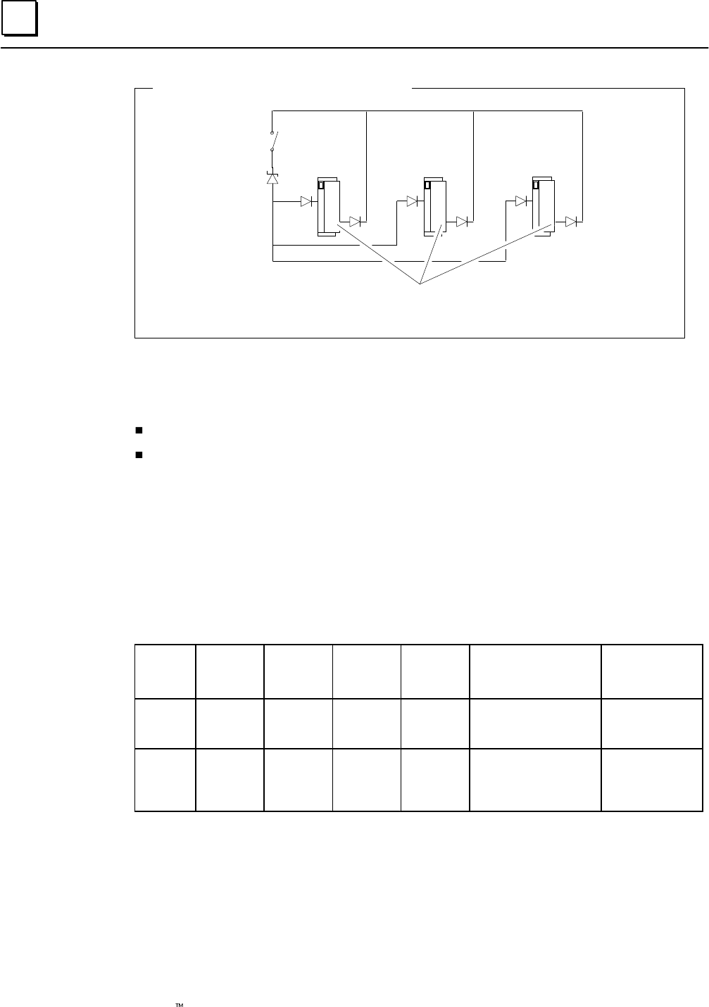
5
5-6 Genius Modular Redundancy Flexible Triple Modular Redundant (TMR) System
User’s Manual –March 1995 GFK-0787B
Single Input Sensor to Triplex Block Group
Field
Switch
Zener
Diode
Power feed outputs require isolation diode when single input device is
wired to more than one block.
Operation of the Input Autotest
The following actions are performed during the Input Autotest:
the power feed outputs * are pulsed Off. Selected input channels are pulsed On.
all associated inputs are checked for their ability to detect the On or Off state, as
appropriate, and a fault is reported if the correct state is not detected..
While it is being tested, a block continues to supply its last valid set of inputs instead of the
physical inputs to the PLCs.
Test Verification
By allowing some inputs to be turned On, the Input Autotest checks its own operation.
The following table shows cycles in which blocks are autotested, and circuits that are
turned On in the same cycle
Block
Type 1st A/T
Cycle 2nd A/T
Cycle 3rd A/T
Cycle 4th A/T
Cycle Circuits Turned
On at the Same
Time
Circuit Fail
Mask
16 Cir-
cuit DC Block A
Block B
Block C
Block C
Block A
Block B
Block B
Block C
Block A
Block A
Block B
Block C
1,3,5,7,10,12,14
2,4,6,8
9,11,13,15
2A55
00AA
5500
32 Cir-
cuit DC Block A
Block B
Block C Block A
Block B
Block C
Block C
Block A
Block B
Block B
Block C
Block A
1,5,9,13,17,21,25,29
2,6,10,14,18,22,26,30
3,7,11,15,19,23,27,31
4,8,12,20,24,28,32
1111 1111
2222 2222
4444 4444
8888 0888
Notes: Bit 16 corresponds to the power feed output. It is always 0.
For 16-Circuit blocks, each circuit is turned On each cycle when looked at across all
3 blocks, but the same circuit is never turned On at more than one block at a time.
For 32 Circuit blocks, almost all circuits are turned On each cycle when looked at
across all 3 blocks, but the same circuit is never turned On at more than one block
at a time.
*also see chapter 8 for installation and wiring information.
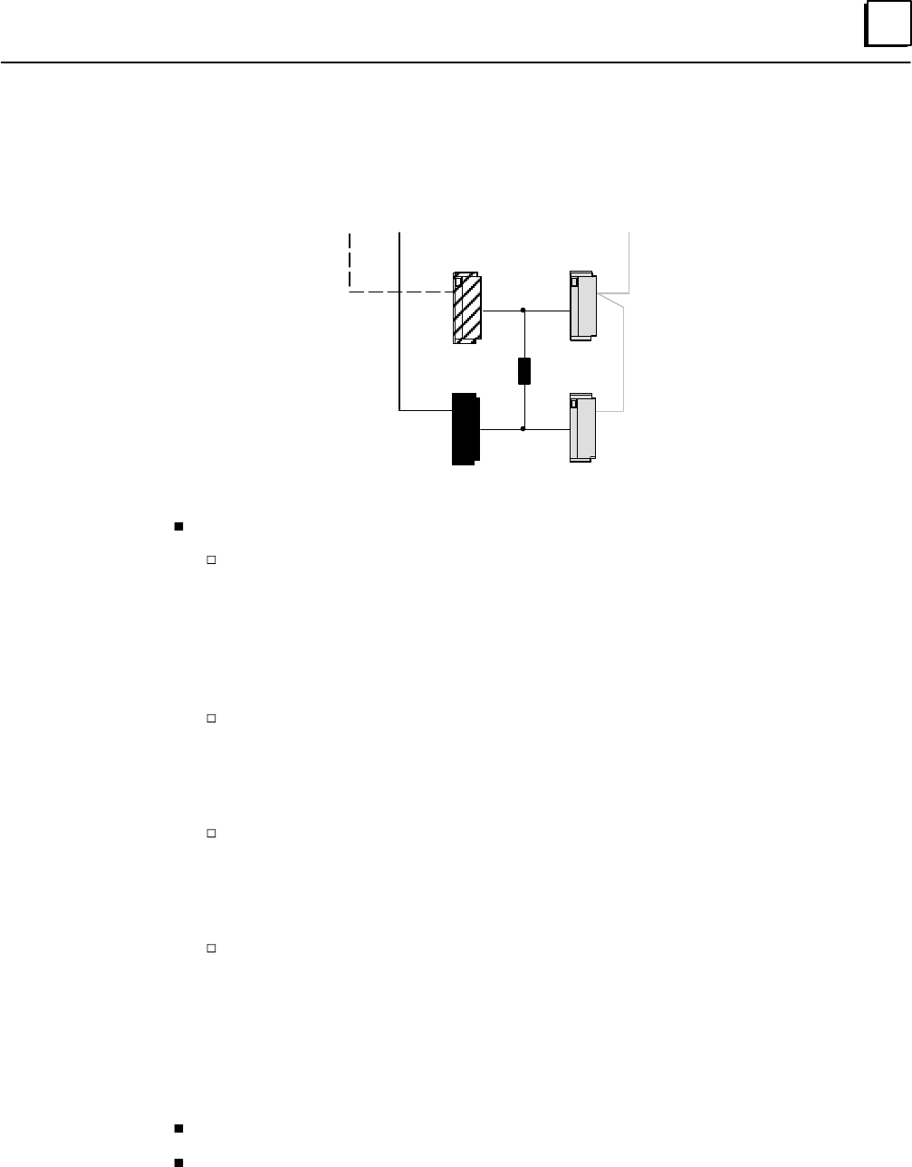
5
5-7GFK-0787B Chapter 5 Diagnostics
Discrete Output Autotest
Discrete output autotest checks the ability of outputs to respond to the commanded output
state.
Load
Bus A Bus BBus C
AB
CD
The discrete output autotest will:
work on outputs that are either on or off, with or without load monitoring.
for normally deenergized outputs that are off when tested, the test detects:
Open Circuit load (if No-load Diagnostic is enabled)
Block A/B short to 0V
Block C/D short to 24V
Any single block open circuit (if No-load Diagnostic is enabled)
Any single block Switch Failed off
for normally deenergized outputs that are on when tested, the test detects:
Open Circuit load (if No-load Diagnostic is enabled)
Any single block open circuit (more precise if No-load Diagnostic is enabled)
Any single block Switch Failed off
for normally energized outputs that are off when tested, the test detects:
Block A/B short to 0V
Block C/D short to 24V
Any single block Switch Failed off
for normally energized outputs that are on when tested, the test detects:
Open Circuit load (if No-load Diagnostic monitoring is enabled)
Any single block open circuit (more precise if No-load Diagnostic is enabled)
Block A/B short to 24
Block C/D short to 0V
Any single block Switch Failed off
Any single block Switch Failed on
detect any output failure that would result in a failure to respond.
although no test results are generated if outputs change state during the test, it does
not cause spurious faults to be logged.
During output autotest, the Genius block group still controls the physical outputs, so output
devices are not affected by the test.
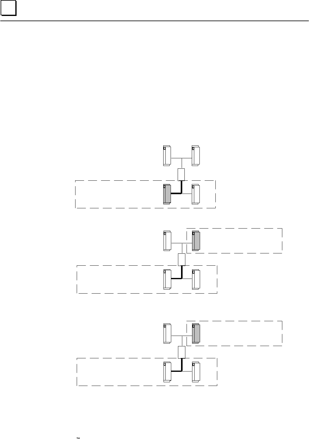
5
5-8 Genius Modular Redundancy Flexible Triple Modular Redundant (TMR) System
User’s Manual –March 1995 GFK-0787B
Operation of the Discrete Output Autotest
The PLC that is presently the autotest master informs the other PLCs (if any) which autotest
group it is about to test.
All PLCs read the diagnostic status of all blocks in the group to be tested, and will ignore any
subsequent faults that may occur in that group.
The autotest master PLC reads the current output state and force state for each circuit in the
output group.
Then, the autotest master pulse-tests the blocks in the output group (details of pulse test
operation are explained on page 5-10). The test sequence is described below.
1. For the 4-block output group, the autotest master overrides the normally
deenergized outputs on block C to ON.
Load
AB
CD
Block C normally deenergized
outputs overridden ON
2. The autotest master pulse-tests block B. Any faults on block B are noted.
Load
AB
CD
Block C outputs still
overridden ON
Block B Pulse-tested
3. If any outputs on block B configured as normally-energized logged a Failed Switch
when pulsed, the master overrides them to OFF.
Load
AB
CD
Block C outputs still
overridden ON
Normally-energized
outputs with Failed Switch
are overridden OFF.
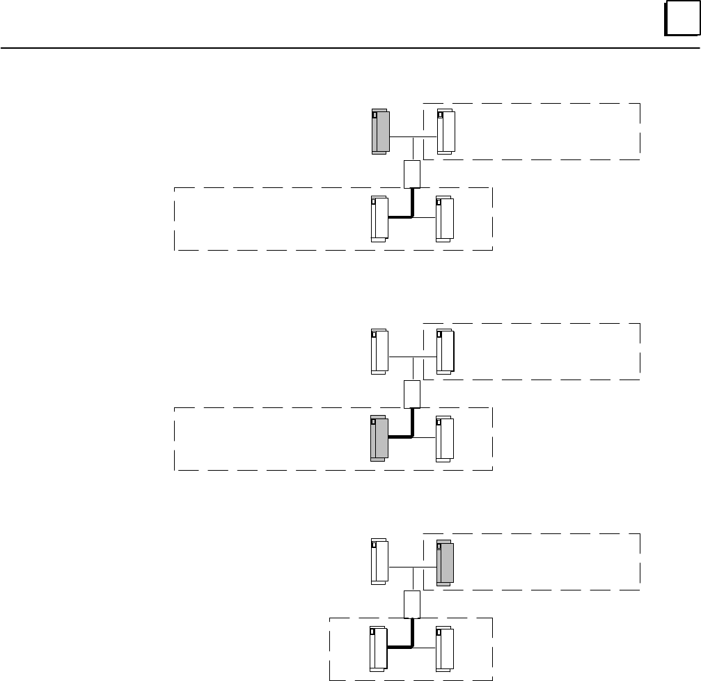
5
5-9GFK-0787B Chapter 5 Diagnostics
4. The autotest master pulse tests Block A. Any faults on block A are noted.
Load
AB
CD
Block C outputs still
overridden ON
Failed Switch outputs still
overridden OFF.
Block A Pulse-tested.
5. The master resets all four blocks in the output group.
6. Overrides on block C are cancelled.
Load
AB
CD
Block C output overrides
cancelled.
Failed Switch outputs still
overridden OFF.
7. The master cancels overrides on block B except for any outputs that have tripped
erroneously.
Load
AB
CD
Overrides conditionally
cancelled.
8. The autotest master repeats the above process for blocks D/A/B, then A/D/C, then
B/C/D.
9. The autotest master reports faults to the other PLCs (if any). All the PLCs log any
faults that occur into their Fault Tables.
10. The autotest master continues testing with the next group.

5
5-10 Genius Modular Redundancy Flexible Triple Modular Redundant (TMR) System
User’s Manual –March 1995 GFK-0787B
Pulse Test Operation
The Output Autotest uses the standard Genius block Pulse Test feature. During this test, the
system is on-line and available.
For the test to be performed:
All blocks in the group must be on-line.
There may be no I/O override applied to any block in the group.
In addition, for each block output that is associated with a given system output within
the group:
there may be no I/O force applied.
there may be no hardware fault (such as a failed switch).
all block outputs associated with the system output must presently be in the
same logical state. (Monitoring of system status references to detect forces and
overrides is discussed later in this chapter).
Outputs that are OFF are pulsed OFF-ON-OFF and checked for correct voltage, for the
presence of diagnostic data, and for correct current (if the No Load diagnostic is enabled). If a
point reports correct voltage and/or current data, the point passes and is not re-pulsed.
However, if a point does not report correct voltage and/or current data, it is retested up to a
maximum of seven times, in successively longer pulses. The ON pulse times begin at
approximately 1.7mS, and can increase up to approximately 20mS. There is a delay of
approximately 5mS to 15mS between successive pulses of the same point.
Outputs that are ON are pulsed ON-OFF-ON. This checks whether a point’s feedback
voltage matches its commanded state. Points are pulsed OFF for approximately 5ms. If the
voltage matches, a point passes. If not, the point is pulsed OFF again, for approximately
7.5mS.
Note that the times given here are typical for 16-circuit blocks (pulse times and quantities are
different for 32-circuit blocks). Actual times in any application depend on the presence of
other scheduled tasks and the configuration of the points.
Note
Use of the Genius output Pulse Test feature from the application
program or Hand-held Monitor is NOT recommended for GMR
applications, since it will produce erroneous results.
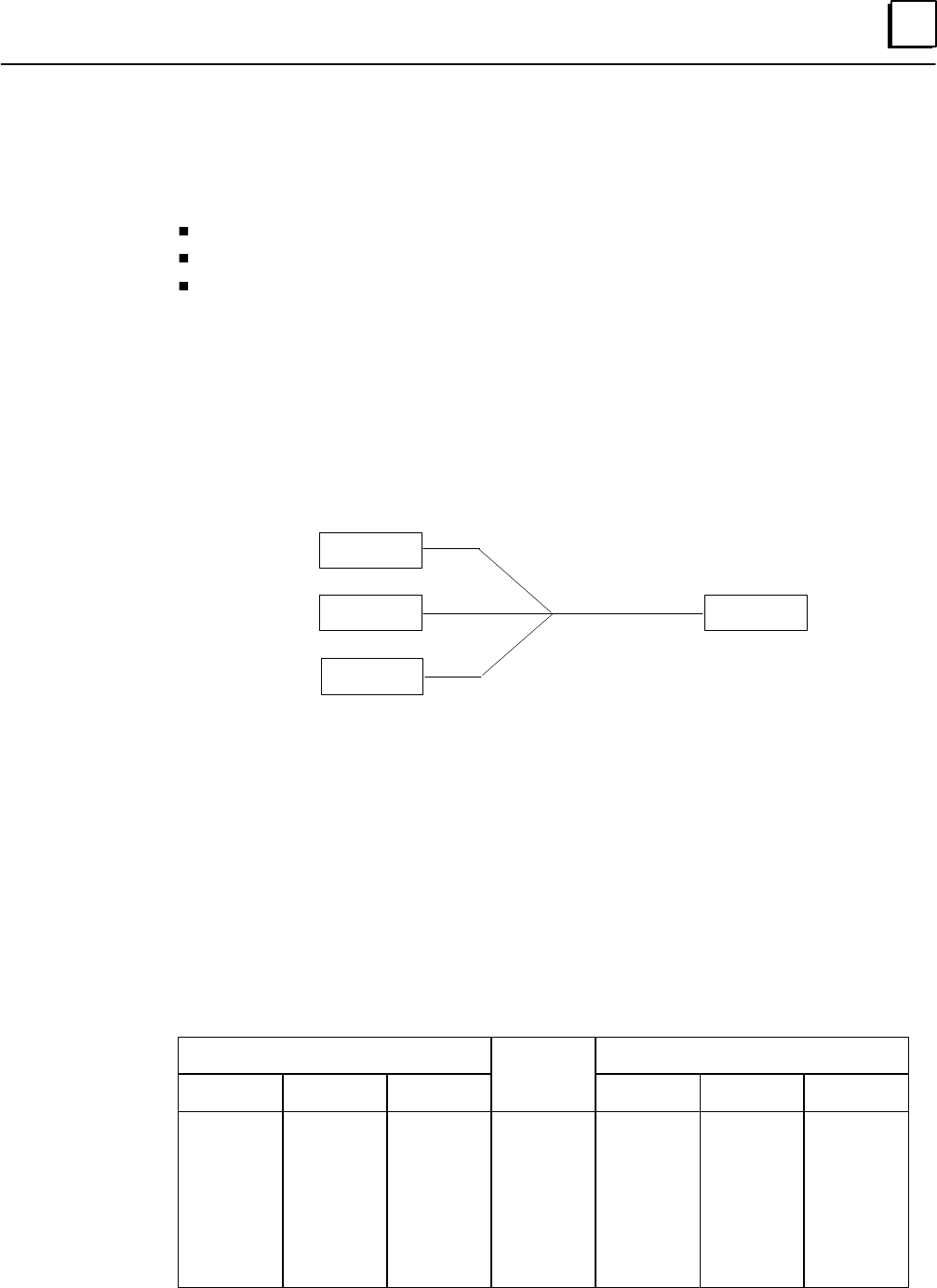
5
5-11GFK-0787B Chapter 5 Diagnostics
GMR Discrepancy Reporting
The GMR software performs discrepancy reporting for:
Voted discrete inputs
Discrete outputs
Analog inputs
There is no discrepancy reporting for analog outputs.
Discrete Input Discrepancy Reporting
As explained in the chapter on PLC operation, the PLC compares corresponding inputs
from bus A, bus B, and bus C, and performs voting:
Field Input Data
Input A
Input B
Input C
0
0
1
PLC Performs
2 out of 3 Voting
0
Single Input Provided
to Application Logic
If there is a discrepancy between any original input data value for an input and its voted input
state, the PLC automatically places a message in the I/O Fault Table, where it is available to the
Logicmaster 90 software and the application program logic. Discrepancy faults are latched.
When a discrepancy occurs, the PLC sets the fault contact for that voted input. See page 5-25
for information about these fault contacts.
Discrepancy signals are filtered for the configured input discepancy filter time to eliminate
transient discrepancies caused by timing differences.
The following table shows possible discrepancies between the input data and voted input data.
Input Data
Voted
Discrepancy
A B C
Voted
Inputs A B C
0
0
0
0
1
1
1
1
0
0
1
1
0
0
1
1
0
1
0
1
0
1
0
1
0
0
0
1
0
1
1
1
0
0
0
1
1
0
0
0
0
0
1
0
0
1
0
0
0
1
0
0
0
0
1
0

5
5-12 Genius Modular Redundancy Flexible Triple Modular Redundant (TMR) System
User’s Manual –March 1995 GFK-0787B
Discrete Output Discrepancy Reporting
Output discrepancy monitoring is the process of monitoring the block output voting function
to detect both processor discrepancies and lost communication between the block and the
other processors. All PLCs periodically monitor all blocks’ discrepancy status. On
interrogation by any PLC, the block responds with a discrepancy message indicating the
discrepant output and disagreeing PLC.
The system uses output discrepancy checking to determine if the output data sent from
each of the PLCs agrees with the voted output state. If a discrepancy check reveals that a
PLC is sending incorrect output data to a block, the GMR system logs an output
discrepancy fault in the I/O fault table and sets the appropriate fault contacts.
The GMR system performs output discrepancy checking whenever it is not performing
input or output autotesting (i.e. between autotests during the autotest interval). It
checks all output blocks in redundant output groups and any non-redundant output
blocks marked for discrepancy checking in the GMR configuration.
How Output Discrepancy Checking is Performed
If the GMR system determines that an output changed state during a discrepancy check, it
attempts up to three times to properly complete the discrepancy check on an output block.
This prevents logging false discrepancy faults that might be caused by the application
program changing the state of an output while a discrepancy check is being performed
Discrete Output Discrepancy Reporting with Dynamic Outputs
Output Discrepancy Checking gives valid results as long an output changes state less
frequently than approximately once per 10 PLC scans. If an output changes state more
rapidly than approximately once per 10 PLC scans, the results of Output Discrepancy
Checking may be ignored. Nuisance discrepancy faults (caused by transitioning outputs)
should NOT ever be logged. However, a message is logged in the PLC fault table. The
message indicates that output discrepancy processing could not be completed for a
device at rack X, slot Y, SBA x due to transitioning outputs.
In an ESD system, outputs are normally static. Outputs that are not static, that is,
outputs that normally change state, may not be autotested as frequently as expected.

5
5-13GFK-0787B Chapter 5 Diagnostics
Analog Input Discrepancy Reporting
If there is a discrepancy in the data from a set of inputs, so that a channel deviates by more
than a configurable percentage from the voted value, the PLC automatically places a message
in the I/O Fault Table where it is available to the Logicmaster 90 software and the application
program logic.
Discrepancy is calculated for engineering units values inputs. Two distinct discrepancy bands
are provided: threshold and limit.
The threshold discrepancy occurs where an A, B, or C engineering units input value
exceeds a specified percentage of the voted value. For example, if channels A, B, and
C report 91, 100, and 111, respectively, the GMR software selects 100 as the
intermediate value. If the threshold discrepancy for the input is set to 10%, this
yields 90 and 110 as the upper and lower threshold discrepancy values. In this
example, channel A is within the threshold band, but channel C is outside, and is
discrepant.
The limit discrepancy occurs where an engineering units input exceeds a given
percentage of the full-scale deflection of the input. For example, if channels A, B, and
C report 9, 10, and 15, respectively, then the GMR software selects 10 as the
intermediate value. If the limit discrepancy is set to 10% of a 200 full-scale deflection
(20 in this case) then no limit discrepancy is reported.
An analog discrepancy is reported where the limit discrepancy and the threshold are both
exceeded. Up to two of the three analog inputs may be discrepant at any given time.
Discrepancy faults are latched, but can be cleared by performing an I/O Fault Reset (see
chapter 7, Programming).
When a discrepancy occurs, the PLC sets the fault contact for that voted input and adapts
according to its configuration. See page 5-25 for information about these fault contacts.
Discrepancy signals are filtered for the configured input discepancy filter time to eliminate
transient discrepancies caused by timing differences.
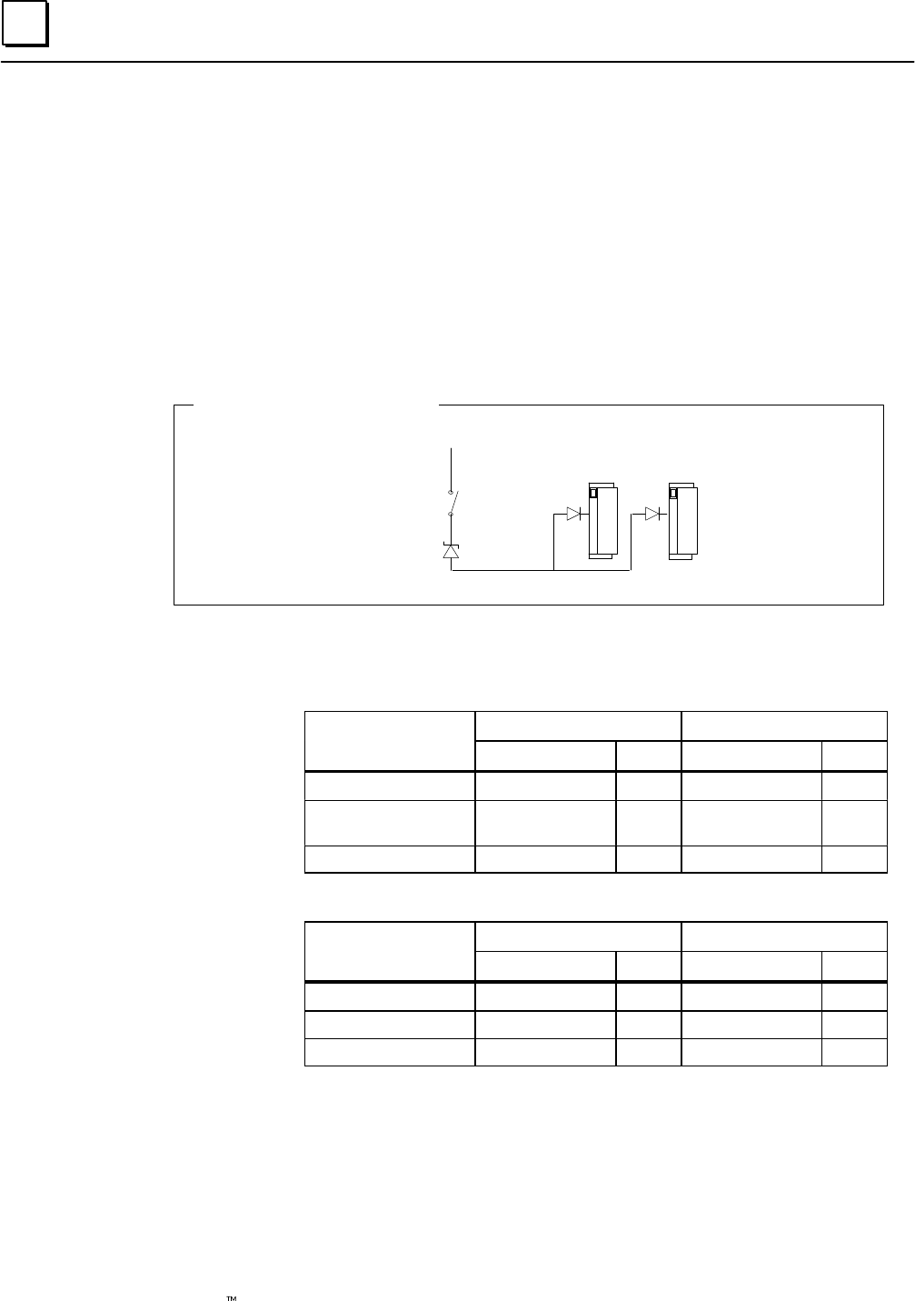
5
5-14 Genius Modular Redundancy Flexible Triple Modular Redundant (TMR) System
User’s Manual –March 1995 GFK-0787B
Input Line Fault Detection in a GMR Application
The 16-circuit Genius blocks are capable of continually monitoring field circuits for input
short circuit or open circuit faults. The blocks detect On, Off, Short Circuit, or Open Wire
conditions on circuits set up as tristate inputs.
If a block is in a “non-GMR” mode, a resistor must be installed in the circuit to provide
Open Wire fault detection. However, if the block is in GMR mode, a zener diode is used
instead to detect short circuits. The diode is installed in series between the field switch
and the tristate input blocks, but physically at the field switch device. The Zener diode
rating is 6.2V.
V+
Block Setup for Tristate Inputs
Field
Switch
Zener
Diode
When a block is in GMR mode, the status and on/off state of a tristate input have
different specifications than they do in non-GMR mode.
Range
Non-GMR GMR
Range
Status Input Status Input
<30% VDC open circuit fault 0 off 0
>50%, < VDC+
–7V Off 0 On 1
>VDC+ –4V On 1 short circuit fault 1
Range
Non-GMR GMR
Range
Status Input Status Input
<4V On 1 short circuit fault 1
>7V, <50% VDC+ Off 0 On 1
>70% VDC+ open circuit fault 0 Off 0
When used with a GMR block, a Genius Hand-held Monitor will correctly report a short
circuit fault instead of Open Circuit.
DC Source
Block
Tristate
Input
Thresholds
DC Sink
Block
Tristate
Input
Thresholds
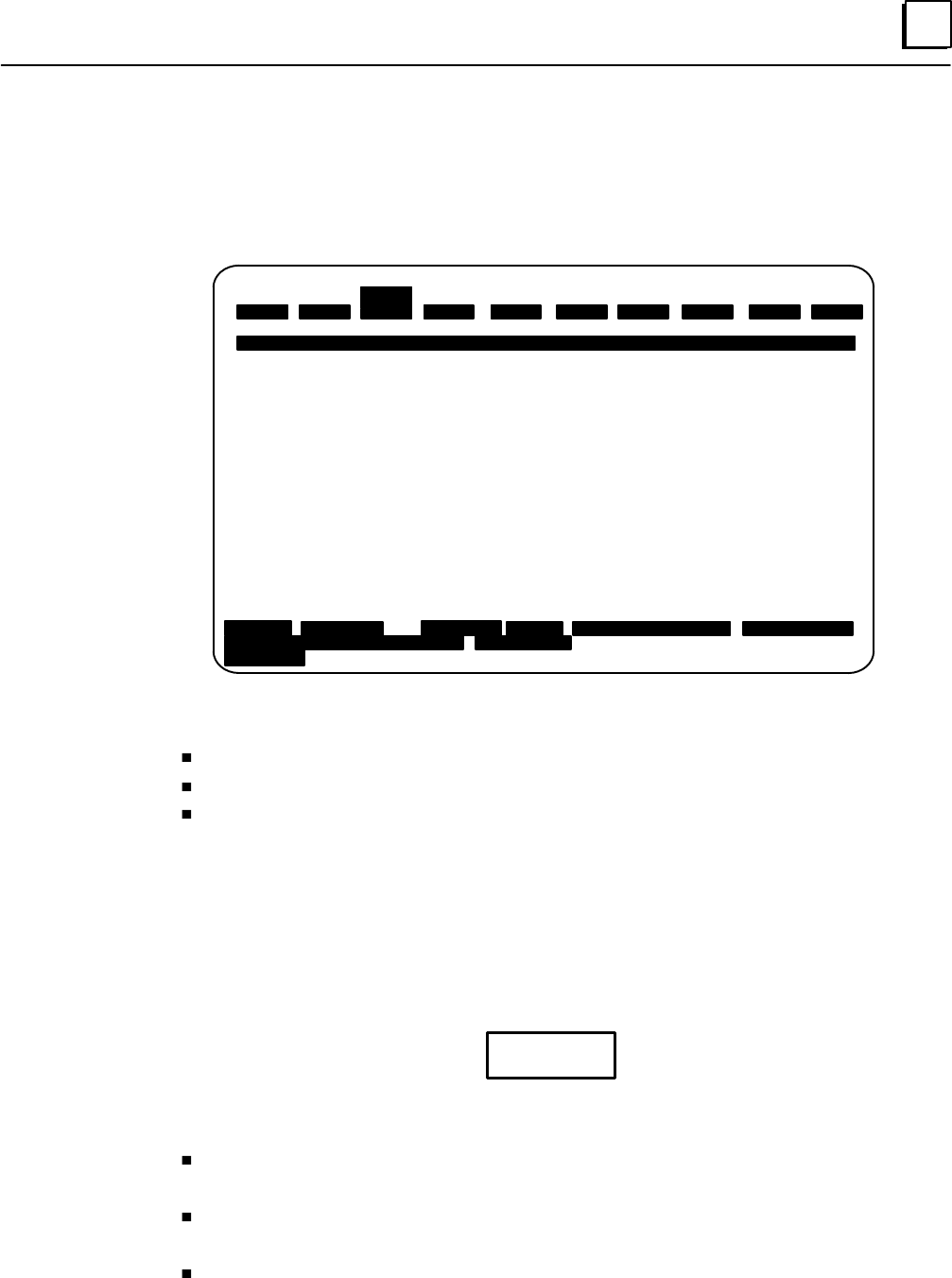
5
5-15GFK-0787B Chapter 5 Diagnostics
The PLC and I/O Fault Tables in a GMR System
Faults and alarms from I/O devices, Bus Controller faults, and bus faults are automati-
cally logged into the Series 90–70 PLC’s I/O Fault Table. Faults can be displayed with
the programmer in either On–Line or Monitor mode.
|PROGRM |TABLES |STATUS | | |LIB |SETUP |FOLDER |UTILTY |PRINT
1plcrun 2passwd 3plcflt 4io flt 5plcmem 6blkmem 7refsiz 8sweep 9clear 10zoom
02 481200 00301010200 0A02 01 01 02 9B03010000000000000000000000000000000000000
>
I / O F A U L T T A B L E
TOP FAULT DISPLAYED: 0007 TABLE LAST CLEARED: 09–21 11:22:17
TOTAL FAULTS: 0007 ENTRIES OVERFLOWED: 00000
FAULT DESCRIPTION: SHORT IN USER WIRING PLC DATE/TIME: 10–14 10:05:13
FAULT CIRC REFERENCE FAULT FAULT DATE TIME
LOCATION NO. ADDR. CATEGORY TYPE M–D H: M: S
___________ _____ _________ ___________________ ________________ _____ ________
0.3.1.1 %QI 00017 FORCED CIRCUIT 03–08 11:23:16
0.3.1.1 %QI 00017 UNFORCED CIRCUIT 03–08 11:23:16
0.3.1.1 %QI 00017 FORCED CIRCUIT 03–08 11:23:16
0.3.1.1 1 %Q 00019 CIRCUIT FAULT DISCRETE FAULT 03–08 11:23:16
0.3.1.1 %QI 00017 FORCED CIRCUIT 03–08 11:23:16
0.3.1.1 3 %Q 00017 CIRCUIT FAULT DISCRETE FAULT 03–08 11:23:16
0.3.1.1 2 %Q 00018 CIRCUIT FAULT DISCRETE FAULT 03–08 11:23:16
ID: RUN/OUT EN 3ms SCAN ONLINE L4 ACC: WRITE LOGIC LOGIC EQUAL
D:\P060\GMRSYS PRG:SYS3
REPLACE
The same fault table features are available in a GMR system, with the following
additional types of messages:
Autotest fault messages (I/O Fault Table)
Discrepancy fault messages (I/O Fault Table)
PLC Fault Table messages for GMR
More fault information can be displayed by pressing CTRL/F, as described on the next page.
Clearing the Fault Tables in a GMR System
Although the Fault Tables seem to operate as they would in a non-GMR system, they are
actually controlled by the GMR software, not the PLC firmware. Therefore, in a GMR
application, the fault tables must be monitored and cleared from the application
program logic.
Caution
Use these %M references to clear the PLC Fault Tables. Do not use the Logicmaster F9 key to
clear the Fault Tables.
To clear the PLC Fault Table in a single PLC, set reference %M12259 to 1 for at least
one PLC sweep in that PLC.
To clear the PLC Fault Table in all PLCs, set reference %M12264 to 1 for at least one
PLC sweep in any PLC.
To clear the I/O Fault Table and corresponding fault contacts in all PLCs, set
reference %M12258 to 1 for at least one PLC sweep in any PLC.
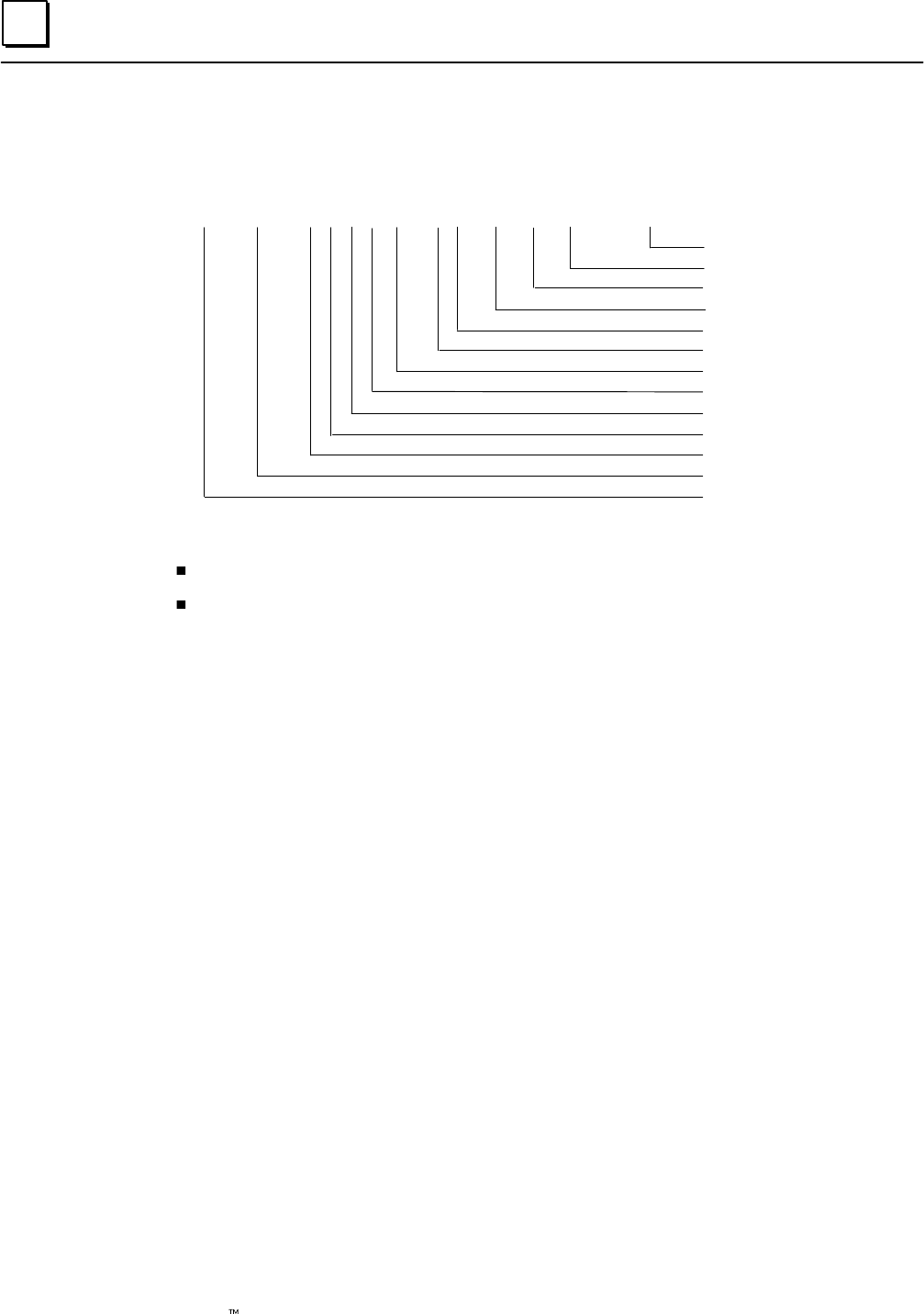
5
5-16 Genius Modular Redundancy Flexible Triple Modular Redundant (TMR) System
User’s Manual –March 1995 GFK-0787B
I/O Fault Table Messages for GMR
I/O Fault Table format is detailed in the Series 90-70 PLC Reference Manual (GFK-0265).
Fault Specific Data
Fault Category
Fault Action
Fault Group
Point
Block
I/O Bus
Slot
Rack
Reference Address
Long/Short
02 1F0100 00030101FF7F 0302 02 00 00 84000000000003
Fault Description
Fault Type
In the I/O Fault Table, the following additional types of messages are available for GMR:
Autotest fault messages
Discrepancy fault messages
These faults have the following fields on the Logicmaster Fault Table display:
Fault Location*: Rack
Slot
Bus: always 1
Block serial bus address
Circuit Number: Block circuit number
Reference Address: Physical I/O reference
Fault Category: Circuit Fault
Fault Type: Discrete Fault
* For autotest faults (only) the fault location given is for block A of the group if the
fault affects all blocks in the group; otherwise, the location is that of the affected
block.
Reporting of No-Load Faults on 4-Block Output Groups
The pairs of source and sink blocks in a four-block output group share loads. If outputs are off,
a No-load will be reported in the normal manner if any block in the group has a no-load
condition. However, if outputs are on and a No-load fault occurs on just one block of the pair,
it does not appear in the fault table because the other block of the pair is still supporting the
load. Therefore, an output No-load fault is reported only if both sink blocks in the group or
both source blocks in the group report a No-load fault.
The fault location listed in the I/O Fault Table is that of the second block reporting the fault.
For example:
0.3.1.1 1 %Q 00019 CIRCUIT FAULT DISCRETE FAULT 03–08 11:23:16
In this example, the location of the output block reporting the fault is rack 0, slot 3, bus 1,
serial bus address 1. However, both of the (source or sink) blocks in that pair actually
have No-load faults for output %Q00019.

5
5-17GFK-0787B Chapter 5 Diagnostics
Displaying Additional Fault Information About I/O Faults (with CTRL/F)
Pressing the programmer CTRL/F keys provides more information about a fault. Entries
that apply to the GMR system are described below.
Fault Description:
Code (Hex) Meaning
00 Loss of Device
F0 Digital Input Autotest Fault
F1 Digital Input Discrepancy Fault
F2 Digital Output Autotest Fault
F3 Digital Output Discrepancy Fault
F4 Analog Input Discrepancy Fault
FF GMR I/O Fault
Fault Specific Data:
Loss of Device Byte 1
Bytes 2 – 5 = 84 (Hex)
= Always 0
Digital Input Discrepancy Byte 1 – 5 = Always 0
Input Autotest Byte 1
Bytes 2 and 3
Byte 4
Byte 5
= Master PLC (AA, BB, or CC (Hex)
= Always 0
= Fail State : (01 = input stuck at 0
(02 = input stuck at 1
= Always 0
Analog Input Discrepancy Byte 1 – 5 = Always 0
Output Autotest Byte 1
Bytes 2 and 3
Byte 4
Byte 5
= Master PLC (AA, BB, or CC (Hex)
= Always 0
= Fault type (see below)
= Always 0
Output Discrepancy Byte 1
Bytes 2 and 3
Byte 4
Byte 5
= Master PLC (AA, BB, or CC (Hex)
= Always 0
= discrepant PLC (AA, BB, or CC (Hex)
= Always 0
Analog Input Discrepancy Byte 1 – 5 = Always 0
GMR I/O Fault Byte 1
Bytes 2 and 3
Byte 4
Byte 5
= Master PLC (AA, BB, or CC (Hex)
= Always 0
= 1 (Logon fault)
= discrepant PLC (AA, BB, or CC (Hex)
Fault Type for Output Autotest
For Output Autotest, the Fault Type byte may have the following content (hex values):
11 Block A & B short circuit to 0V 22 Block B switch failed off
12 Block C & D short circuit to +24V 23 Block C switch failed off
13 Block A cannot turn on 24 Block D switch failed off
14 Block B cannot turn on 25 Block A not connected to Block B
15 Block C cannot turn on 26 Block C not connected to Block D
16 Block D cannot turn on 27 Block A cannot turn off
17 Load disconnection 28 Block B cannot turn off
18 No Load connection on Block A 29 Block A & B cannot turn off
19 No Load connection on Block B 2A Block C cannot turn off
1A No Load connection on Block C 2B Block D cannot turn off
1B No Load connection on Block D 2C Block C & D cannot turn off
1C Inconsistent No Load reporting 30 Force override (spurious trip)
21 Block A switch failed off

5
5-18 Genius Modular Redundancy Flexible Triple Modular Redundant (TMR) System
User’s Manual –March 1995 GFK-0787B
PLC Fault Table Messages for GMR
The following tables lists PLC Fault Table messages for GMR.. If you need additional
help, call GE Fanuc Technical Service at 1–800–828–5747.
Code Message Meaning
100 No CPU Clock There is no PLC clock present
100 No PLC Clock There is no PLC clock present
101 Illegal state step Internal GMR error: invalid step
101 Illegal trans code Internal GMR error: invalid transition code
101 Bad trans x from wwww Internal GMR error: attempted transition to invalid step
100+
GBC ID CFPT, 0 attempts wwww Number of attempts exhausted while trying to send a COMREQ
10009 GMRx ornge GBC g req Out of range Bus Controller (g) was requested by GMRx module
10009 GMRx bad GBC g req Unconfigured Bus Controller (g) was requested by GMRx module
10010 GMRx ornge GBC g rel Out of range Bus Controller (g) was released by the GMRx module
10010 GMRx bad GBC g rel Unconfigured Bus Controller (g) was released by the GMRx module
10011 GMRx ornge GBC g flt Out of Range Bus Controller (g) was faulted by the GMRx module
10011 GMRx bad GBC g flt Unconfigured Bus Controller (s) was faulted by the GMRx module
1Unauthorized GMR Access Initialization module was invoked with incorrect password
10102 Incorrect GMR Version Initialization module was called with incorrect version number
10103 GMR Software Exception An invalid call number was detected
10104 Invalid GMR Pointer Initialization module was invoked with invalid pointer for diagnostics area
10109 Prog Checksum Timeout PLC didn’t calculate the program checksum within 10 seconds
10110 Invalid Bus Address Initialization detected bus addresses not equal to 29, 30, or 31
10111 Sync Not Possible Synchronization cannot be performed
10112 Output discrepancy Output discrepancy detected
10113 Miscomp, no more retries Sync detected miscompare
10114 GMR Coldstart GMR is performing coldstart
10115 GMR Warmstart GMR is performing a warmstart
10116 Cannot get all GBCs Cannot acquire all GBCs during initialization
10117 Cannot do VME Write The VME Write to 7F3h was unsuccessful
10119 Invalid Switch Case An invalid case condition was detected during a switch
10120 Failed Disable Ops The Disable Outputs command (COMREQ) failed to complete successfully
10121 Failed Enable Ops The Enable Outputs command (COMREQ) failed to complete successfully
10122 Failed Set GMR Mode The Set GMR Mode command (COMREQ) failed to complete successfully
10123 Failed DG Dgrams The Clear Datagrams Dequeue command (COMREQ) failed to complete successfully
10124 Failed Read Address The Read Bus Address command (COMREQ) failed to complete successfully
10129 Num dequeues = n N dequeue entries were dequeued at startup
10130 Program mismatch A/B PLCs A and B program mismatch, C is not online
10131 Program mismatch B/C PLCs B and C program mismatch, A is not online
10132 Program mismatch A/C PLCs A and C program mismatch, B is not online
10133 Program mismatch A/B&C PLC A program mismatch with B and C
10134 Program mismatch B/A&C PLC B program mismatch with A and C
10135 Program mismatch C/A&B PLC C program mismatch with A and B
10136 Program mismatch A/B/C All three PLCs mismatch
10137 Program changed A PLC A program changed
10138 Program changed B PLC B program changed
10139 Program changed C PLC C program changed
10140 Config mismatch A/B PLCs A&B config mismatch, C not online
10141 Config mismatch B/C PLCs B and C config mismatch, A is not online
10142 Config mismatch A/C PLCs A and C config mismatch, B is not online
10143 Config mismatch A/B&C PLC A config mismatch with B and C
10144 Config mismatch B/A&C PLC B config mismatch with A and C
10145 Config mismatch C/A&B PLC C config mismatch with A and B

5
5-19GFK-0787B Chapter 5 Diagnostics
Code MeaningMessage
10146 Config mismatch A/B/C All three PLCs mismatch
10147 Config changed A PLC A config changed
10148 Config changed B PLC B config changed
2 Config changed C PLC C config changed
10201 Unauthorized GMR Access Inter-PLC Comms module was invoked with incorrect password
10202 Incorrect GMR Version Inter-PLC Comms module has incorrect GMR version number
10203 GMR Software Exception Inter-PLC Comms module was called with invalid call number
10204 Invalid GMR Pointer Inter-PLC Comms module was called with invalid data pointer
10211 Comms Fail PLC A bus a Communications with PLC A has failed on bus a
10212 Comms Fail PLC B bus a Communications with PLC B has failed on bus a
10213 Comms Fail PLC C bus a Communications with PLC C has failed on bus a
10221 Comms Fail PLC A bus b Communications with PLC A has failed on bus b
10222 Comms Fail PLC B bus b Communications with PLC B has failed on bus b
10223 Comms Fail PLC C bus b Communications with PLC C has failed on bus b
10241 Big err rate, PLC A on a PLC detected a high data CRC failure rate communicating with PLC A on bus a
10242 Big err rate, PLC A on b PLC detected a high data CRC failure rate communicating with PLC A on bus b
10243 Big err rate, PLC B on a PLC detected a high data CRC failure rate communicating with PLC B on bus a
10244 Big err rate, PLC B on b PLC detected a high data CRC failure rate communicating with PLC B on bus b
10245 Big err rate, PLC C on a PLC detected a high data CRC failure rate communicating with PLC C on bus a
10246 Big err rate, PLC C on b PLC detected a high data CRC failure rate communicating with PLC C on bus b
10251 Invalid Switch Case GMR2 software detected an illegal internal condition
10301 Unauthorized GMR access Fault Processor Module was invoked with incorrect password
10302 Incorrect version number Fault Processor Module was invoked with incorrect version number
10303 Invalid call number Call number was invalid
10305 Invalid GMR Pointer The supplied diagnostics pointer is out of range for the required memory type
10306 Invalid Block Size Incorrect block size was specified
10307 Invalid Digital Address Incorrect address of digital I/O was specified
10308 Invalid Analog Address Incorrect address of analog I/O was specified
10310 Invalid block type Block type currently unsupported
10311 GMR3 Rr Ss comreq Fail A COMREQ sent by GMR to a bus controller in rack r slot s has failed
10312 GMR S/W Except. %L %L range error
10313 Value out of range Calculated value is out of range
10322 IO Reset Seq Timeout I/O reset timed out in step 2
10323 IO Reset Seq Timeout I/O reset timed out in step 4
10324 IO Reset Seq Timeout I/O reset timed out in step 6
10328 IO Reset Seq Timeout I/O reset timed out in step 8
10330 IO Reset Seq Timeout I/O reset timed out in step 10
10601 Unauthorized GMR Access I/O Module was invoked with the incorrect password
10602 Invalid GMR Version I/O Module S/W version does not match expected version
10603 GMR S/W Except. Call I/O Module was invoked with incorrect call number
10604 GMR S/W Except, %L I/O Module was invoked with out of range input parameters
10607 Invalid Switch Case No cases satisfied by switch condition
10801 Unauthorized GMR Access GMR Configuration Module was invoked with incorrect password
10802 GMR S/W Except Null FH GMR Configuration Module failed to load fault handler
10802 GMR S/W Except I/O FH GMR Configuration Module encountered an error loading the fault handler
10803 GMR S/W Except call no GMR Configuration Module detected call number exception
10804 ADL rack r slot s flt GMR Configuration Module failed to build active device list
10805 GMR S/W Except %L GMR Configuration Module detected invalid diagnostic or error references
10806 GMR Invalid switch GMR Configuration Module detected invalid switch case
10810 GMR config util invalid GMR Config Module detected incompatibility with configuration utility
10811 GMR cfg err GBCxx GMR Configuration Module detected invalid GBC record xx in the config data
10812 GMR cfg err GBCxx I/O yy GMR Configuration Module detected invalid GBC record yy in GBC record xx of the
config data
10813 GMR cfg err CPU type GMR Configuration Module detected incompatible CPU type in the config data

5
5-20 Genius Modular Redundancy Flexible Triple Modular Redundant (TMR) System
User’s Manual –March 1995 GFK-0787B
Code MeaningMessage
10814 GMR cfg err no of PLCs GMR Configuration Module detected more than 3 PLCs in the config data
10815 GMR cfg err W/dog timer GMR Configuration Module detected invalid watchdog time in the config data
10817 GMR Cfg Err %R usage GMR Configuration Module detected insufficient %R registers
10818 GMR cfg err %AI Usage GMR Configuration Module detected insufficient PLC Analog Inputs
10819 GMR cfg err comreq %R GMR Configuration Module detected invalid positioning of the comreq status %R
area
10820 GMR cfg err Tx global GMR Configuration Module detected invalid positioning of the Tx global comms %R
area
10821 GMR cfg err Rx global GMR Configuration Module detected invalid positioning of the Rx global comms %R
area
10822 GMR cfg err I/O > max GMR Configuration Module detected that the maximum I/O points has been exceed-
ed
10823 GMR cfg err voted DIN GMR Configuration Module detected that the maximum number of voted digital
inputs has been exceeded
10824 GMR cfg err voted AIN GMR Configuration Module detected that the maximum number of voted analog
inputs is exceeded
10825 GMR cfg err redund O/P GMR Configuration Module detected that the maximum number of redundant out-
puts is exceeded
10826 GMR cfg err alpha rack GMR Configuration Module detected that alpha inter-PLC GBC is in an invalid rack
10827 GMR cfg err alpha slot GMR Configuration Module detected that alpha inter-PLC is in an invalid slot
10828 GMR cfg err beta rack GMR Configuration Module detected that beta inter-PLC is in an invalid rack
10829 GMR cfg err beta slot GMR Configuration Module detected that beta inter-PLC is in an invalid slot
10830 GMR cfg err %M sync GMR Configuration Module detected invalid positioning of the %M sync area
10831 GMR cfg err %R sync GMR Configuration Module detected invalid positioning of the %R sync area
10832 GMR cfg err %R temp GMR Configuration Module detected invalid positioning of the %R temp %M sync
area
10833 GMR cfg err %R A/T int GMR Configuration Module detected invalid positioning of the %R autotest interval
pointer
10834 GMR cfg err ssu flt act GMR Configuration Module detected invalid system startup fault action
10835 GMR cfg err syc flt act GMR Configuration Module detected invalid startup sync fault action
10837 GMR cfg err no of GBCs GMR Configuration Module detected invalid number of GBCs
10840 GMR version MM.mmE GMR software version number
10841 Cfg util ver MM.mmE GMR config utility version number
10842 GMR config crc 0xXXXX Config utility CRC value
10843 XXXXXXXXXXXXXXXXXXXX First 20 characters of config description
10844 XXXXXXXXXXXXXXXXXXXX Remaining characters of description
10850 Invalid Dig I/P data Invalid data detected in voted digital input record
10851 Invalid NV Dig I/P data Invalid data detected in nonvoted digital input record
10852 Invalid Ana I/P data Invalid data detected in voted analog input record
10853 Invalid NV Ana I/P data Invalid data detected in nonvoted analog input record
10860 GMR cfg err %R Write %R register external device write access range is invalid
10861 GMR cfg err %AI Write %AI register external device write access range is invalid
10862 GMR cfg err %AQ Write %AQ register external device write access range is invalid
10863 GMR cfg err %I Write %I register external device write access range is invalid
10864 GMR cfg err %Q Write %Q register external device write access range is invalid
10865 GMR cfg err %T Write %T register external device write access range is invalid
10866 GMR cfg err %M Write %M register external device write access range is invalid
10867 GMR cfg err %G Write %G register external device write access range is invalid
10870 Shutdown in hh mm ss System simplex shutdown in hh hours, mm minutes and ss seconds
10871 Shutdown Cancelled System simplex shutdown cancelled
10872 System Shutdown System has shut down
10894 Config changed r.s.b.d. The block-level configuration was changed by the specified device.
10898 GMR Fault Handler Error Fault handler received a fault for an invalid discrete block
10899 GMR Fault Handler Error Fault handler received a fault for an invalid analod block
10902 User_IF–GMR version Module version number does not match the GMR system version number

5
5-21GFK-0787B Chapter 5 Diagnostics
Code MeaningMessage
10903 User_IF–Invalid Table Module was called with extended mode table number when the module was in nor-
mal mode
10903 Bad Table c (h) Module was called with an invalid table number (c=requested table in decimal,
h=requested table in hexadecimal)
10905 User_IF–Invalid Range Start or end address parameter is out of range for the specified table type
10906 User_IF–Table Space Destination parameter is out of range for the destination type of memory
10907 No fault contacts An attempt was made to read fault contact data, but no fault contacts were configured
10908 Bad blk loc r.s.b.d. An attempt was made to read an I/O shutdown timer for an invalid block Generated
by GMR_09.
10909 Bad GBC Loc r.s. An attempt was made to read all I/O shutdown timers for an invalid GBC. Generated
by GMR_09.
11001 Null GMR Configuration Configuration Module has detected a Null GMR configuration
11101 Unauthorized GMR Access GMR Configuration Module was invoked with incorrect password
11102 GMR S/W Except. %L %L parameter out of range
11201 Unauthorized GMR Access GMR Configuration Module was invoked with the incorrect password
11202 GMR S/W Except %L %L parameter out of range
11401 Unauthorized GMR Access GMR14 was invoked with the incorrect password
11402 Incorrect GMR Version GMR14 version does not match the GMR system version number
11403 GMR Software Exception Invalid call number was detected
11404 Invalid GMR Pointer The error code pointer was out of bounds
11410 GMR1–IS x at y GMR1state machine went to step x (illegal). Step no. at offset y in GMR1 diagnostics
11411 GMR1–ST x at y GMR1 state mach. exceeded allowed time in step x. Step no. at offset y in GMR1 diag-
nostics
11412 GMR1–IW x GMR1 has output an illegal waycode of x
11413 GMR1–tmplt too small GMR14 has detected an internal error condition
11415 GMR2–IS x at y GMR2state machine went to step x (illegal). Step no. at offset y in GMR2 diagnostics
11416 GMR2–ST x at y GMR2 state mach. exceeded allowed time in step x. Step no. at offset y in GMR2 diag-
nostics
11417 GMR2–IW x GMR2 has output an illegal waycode of x
11418 GMR2–tmplt too small GMR14 has detected an internal error condition
11420 GMR3–IS x at y GMR3state machine went to step x (illegal). Step no. at offset y in GMR3 diagnostics
11421 GMR3–ST x at y GMR3 state mach. exceeded allowed time in step x. Step no. at offset y in GMR3 diag-
nostics
11422 GMR3–IW x GMR3 has output an illegal waycode of x
11423 GMR3–tmplt too small GMR14 has detected an internal error condition
11430 GMR6–IS x at y GMR6state machine went to step x (illegal). Step no. at offset y in GMR6 diagnostics
11431 GMR6–ST x at y GMR6 state mach. exceeded allowed time in step x. Step no. at offset y in GMR6 diag-
nostics
11432 GMR6–IW x GMR6 has output an illegal waycode of x
11433 GMR6–tmplt too small GMR14 has detected an internal error condition
11440 GMR8–IS x at y GMR8state machine went to step x (illegal). Step no. at offset y in GMR8 diagnostics
11441 GMR8–ST x at y GMR8 state mach. exceeded allowed time in step x. Step no. at offset y in GMR8 diag-
nostics
11442 GMR8–IW x GMR8 has output an illegal waycode of x
11443 GMR8–tmplt too small GMR14 has detected an internal error condition
11445 GMR11–IS x at y GMR11 statemachine went to step x (illegal). Step no. at offset y in GMR11 diagnos-
tics
11446 GMR11–ST x at y GMR11 state mach. exceeded allowed time in step x. Step no. at offset y in GMR11 diag-
nostics
11447 GMR11–IW x GMR11 has output an illegal waycode of x
11448 GMR11–tmplt too small GMR14 has detected an internal error condition
11450 GMR12–IS x at y GMR12 statemachine went to step x (illegal). Step no. at offset y in GMR12 diagnos-
tics
11451 GMR12–ST x at y GMR12 state mach. exceeded allowed time in step x. Step no. at offset y in GMR12 diag-
nostics
11452 GMR12–IW x GMR12 has output an illegal waycode of x

5
5-22 Genius Modular Redundancy Flexible Triple Modular Redundant (TMR) System
User’s Manual –March 1995 GFK-0787B
Code MeaningMessage
11453 GMR12–tmplt too small GMR14 has detected an internal error condition
11455 GMR15–IS x at y GMR15 statemachine went to step x (illegal). Step no. at offset y in GMR15 diagnos-
tics
11456 GMR15–ST x at y GMR15 state mach. exceeded allowed time in step x. Step no. at offset y in GMR15 diag-
nostics
11457 GMR15–IW x GMR15 has output an illegal waycode of x
11458 GMR15–tmplt too small GMR14 has detected an internal error condition
11501 Unauthorized GMR Access GMR15 was invoked with incorrect password
11502 Incorrect GMR Version GMR15 version number does not match the GMR system version number
11503 GMR Software Exception An invalid call number was detected
11504 Invalid GMR Pointer The error code pointer was out of bounds
11505 More than 1 Master GMR15 detected that more than 1 PLC was operating as master
11506 Invalid Switch Case GMR detected an illegal internal condition
11507 Discrep NAK PLC A PLC A failed to acknowledge discrepancy results
11508 Discrep NAK PLC B PLC B failed to acknowledge discrepancy results
11509 Discrep NAK PLC C PLC C failed to acknowledge discrepancy results
11510 Disc results read fault The PLC was unable to read output discrepancy results data from the master PLC
11511 DQ x.y.1.z –> d/f/s The PLC expected to dequeue an input autotest results datagram from the device at
rack x, slot y, SBA (serial bus address) z. Instead, an invalid datagram was dequeued
with function code f and subfunction code s from SBA (bus address) d
11511 CQ x.y.1.z –> d/f/s The PLC expected no datagram to be in the queue for the device at rack x, slot y, seri-
al bus address z. Instead, an invalid datagram was found with function code f, and
subfunction code s, from serial bus address d
11513 Xtalk results read flt Non-master could not read input autotest results from master PLC
11521 CR fail x.y.l.z f/s COMREQ with function code f and subfunction code s failed when sent to the device
at rack x, slot y, SBA z
11522 Trans x.y.l.z cccccccc Output discrepancy processing could not be completed for the channels marked in c
on the device at rack x, slot y, SBA z,due to transitioning outputs
11523 Null timeout from PLC A Timeout occurred while waiting for PLC A to transmit a null test number
11524 Null timeout from PLC B Timeout occurred while waiting for PLC B to transmit a null test number
11525 Null timeout from PLC C Timeout occurred while waiting for PLC C to transmit a null test number
11530 I/O S/D r.s.b.d I/O Shutdown on the specified block
11530 I/O S/D cancel r.s.b.d I/O Shutdown cancelled on the specified block
11530 I/O S/D 8hrs r.s.b.d I/O Shutdown in 8 hours on the specified block
11530 I/O S/D 1hr r.s.b.d I/O Shutdown in 1 hour on the specified block
1rsdd I/P A/T res timeout A/T results for SBA dd on GBC at rack r slot s
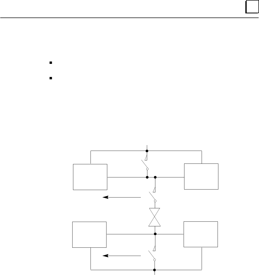
5
5-23GFK-0787B Chapter 5 Diagnostics
Manual Output Controls and Diagnostics
Safety systems are often provided with controls for manual trip and manual override.
A manual trip causes the output to assume the alarm condition. For example, a
normally-energized output would be de-energized.
A manual override causes the output to remain in the normal condition. For
example, a normally-energized output is held energized.
These manual controls can be implemented either in hardware, as represented below, or in
software. If the software method is used, the GMR autotest and fault processing operations
are unaffected.
Hardware control usually consists of switch contacts applied to the output circuit, as shown
below for a normally-energized output.
Source
Genius
Block
Source
Genius
Block
Sink
Genius
Block
Sink
Genius
Block
Manual
Override
+24V
System Input Manual Trip
System Input
Manual
Override
LOAD
+0 VDC
In this circuit, operation of either the trip or override switch can cause no-load faults, state
faults, and autotest faults to be generated. If these manual inputs are wired in the GMR
system, fault reporting is modified to suppress no-load faults and Failed Switch faults. Use of
manual controls does not affect fault reporting for Short Circuit, Overtemperature, Overload,
or Discrepancy faults.
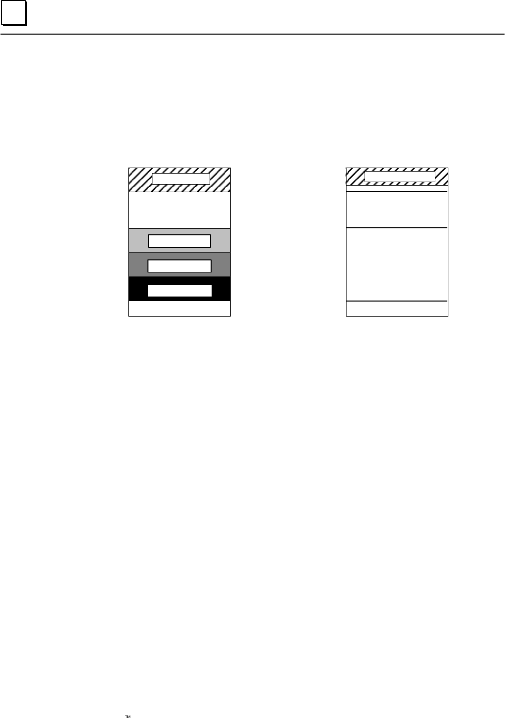
5
5-24 Genius Modular Redundancy Flexible Triple Modular Redundant (TMR) System
User’s Manual –March 1995 GFK-0787B
Monitoring Manual Output Controls
The operation of manual trip and output override devices can be monitored and reported by
connecting them as inputs to Genius blocks.
These inputs should be configured to use references at the end of the Discrete Input Table
shown as “reserved inputs” below.
Discrete Input Table
Voted Inputs
Available for
Non-voted Inputs
Bus A inputs
Bus B inputs
Bus C inputs
Reserved inputs
Discrete Output Table
Logical Outputs
Available for
Non-voted Outputs
Physical Outputs
Reserved memory
%I0001
%I1024
or
%I12288
%Q1024
or
%Q12288
%Q0001
There is a one-to-one correspondence between Reserved Inputs and physical outputs.
The GMR software in each PLC automatically monitors the Reserved Inputs. On detection of
either manual control, it disables the appropriate Genius diagnostics and the output autotest
for the corresponding output circuit(s).
The application program must not command pulse testing on GMR outputs.
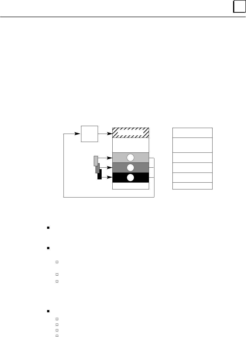
5
5-25GFK-0787B Chapter 5 Diagnostics
Fault, No Fault, and Alarm Contacts
Fault and No Fault contacts can optionally be used to detect fault or lack of fault
conditions on a discrete (%I or %Q) or analog (%AI or %AQ) reference. They can also be
programmed with the Series 90-70’s built-in fault-locating references. In a GMR system,
there are fault contacts associated with voted inputs, with the original block inputs, and
with logical outputs. Alarm contacts can also be used to detect high or low alarm
conditions on an analog (%AI or %AQ) reference. See the Programming chapter for
information about using these contacts.
Discrete Input Fault Contacts for GMR
In the discrete Input Table there are fault contacts associated with each item of voted
input data, non-voted input data, and “raw” data input from bus A, B, and C:
Discrete Input Table
Voted Inputs
Non-voted Inputs
Input
Voting
Logic
Bus A inputs A
B
C
Bus B inputs
Bus C inputs
Reserved inputs
Conditions that Cause these
Fault Contacts to be Set
Any fault
Genius fault
Autotest fault
Genius fault
Autotest fault
Discrepancy fault
Genius fault
Autotest fault
Discrepancy fault
Genius fault
Autotest fault
Discrepancy fault
Genius fault
•
•
•
•
•
•
•
•
•
•
•
•
•
(see text below)
Conditions that Cause Discrete Input Fault Contacts to be Set
For more information about fault contacts, see page 7-21.
For the voted input, a fault contact is set if any of the physical inputs has an
associated fault contact set. For example, if a there is an autotest fault on input A, a
fault contact is set both for input A and for the voted input.
For non-voted inputs, the single fault contact is associated with the physical input. It
is set under the following conditions:
Autotest fault. Set on digital inputs configured for autotesting, if autotesting
detects a fault.
Genius faults, including Loss of Block.
Line fault. These are a feature of the 16-circuit DC blocks. To report line faults, an
input must be configured for tristate operation.
For blocks in GMR mode, a line fault represents a short circuit fault on the field wiring.
For non-GMR blocks, a line fault represents an open circuit fault in the field wiring.
For bus A, bus B, and bus C inputs, fault contacts are set under the following conditions:
Autotest fault (see above).
Line fault (see above).
Genius faults, including Loss of Block.
Discrepancy between the raw input data, and the corresponding voted input.
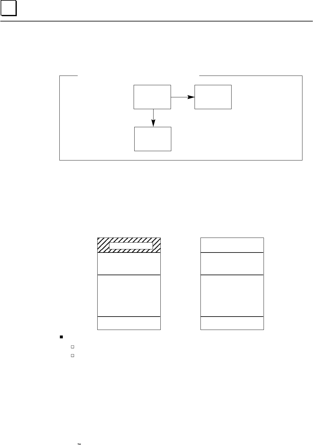
5
5-26 Genius Modular Redundancy Flexible Triple Modular Redundant (TMR) System
User’s Manual –March 1995 GFK-0787B
Discrete Output Fault Contacts for GMR
For discrete outputs, the fault contact is associated with the logical outputs (outputs from the
application program).
Logical
reference Physical
reference
Fault
contact
Contact References Associated with an Output
These logical references are copied to the physical output references. If a fault is detected on a
physical output, the fault contact associated with that output’s logical reference is set.
Conditions that Cause Discrete Output Fault Contacts to be Set
The following illustration summarizes the conditions that cause discrete output fault contacts
to be set for logical, physical, and non-redundant outputs.
Discrete Output Table
Logical Outputs
Available for
Non-redundant Outputs
Physical Outputs
Reserved memory
Any fault
Genius fault
Discrepancy fault
Genius fault
Autotest fault
Discrepancy fault
•
•
•
•
•
•
Genius fault
Discrepancy fault
•
•
Conditions that Cause these
Fault Contacts to be Set
(see the text below)
For redundant outputs, the fault contact is set and fault messages logged for:
Autotest fault
Genius faults including Loss of Block, and the following additional faults:
Failed switch: Occurs if the actual output state differs from the commanded
state.
No-load fault: For 16-circuit blocks only, individual outputs can be
configured to enable or disable reporting No-load faults. The minimum load
current required to assure proper no-load reporting is 100mA (not 50mA, as
it would be for a block not used in a GMR group).
For a 4-block group, a system output no-load fault is produced if outputs are
ON; blocks A and B or blocks C and D report no-load faults.

5
5-27GFK-0787B Chapter 5 Diagnostics
Short circuit fault
Overtemperature fault
Overload fault
Discrepancy
The blocks each report the discrepancy status for the data from each PLC, together
with the PLC online/offline status.
All PLCs periodically monitor all blocks’ discrepancy status. Three discrepancy bits
are maintained for each output; one for each of the PLCs. One of the bits is set if a
block reports a discrepancy for any of its outputs.
For non-redundant outputs, the single fault contact is associated with the physical
output. The fault contact is set under the following conditions:
Discrepancy fault
Genius faults including Loss of Block, and the following additional faults:
Failed switch: Occurs if the actual output state differs from the commanded
state.
No Load fault: For 16-circuit blocks only, individual outputs can be
configured to enable or disable reporting No-load faults. The minimum load
current required to assure proper no-load reporting is 50mA (not 100mA, as
it would be for a block in a GMR group).
For a single block, no-load fault reports for block outputs that are ON may
be generated at any time except during a Pulse Test. For block outputs that
are OFF, no-load fault reports are generated during a Pulse Test.
Short Circuit fault.
Overtemperature fault
Overload fault
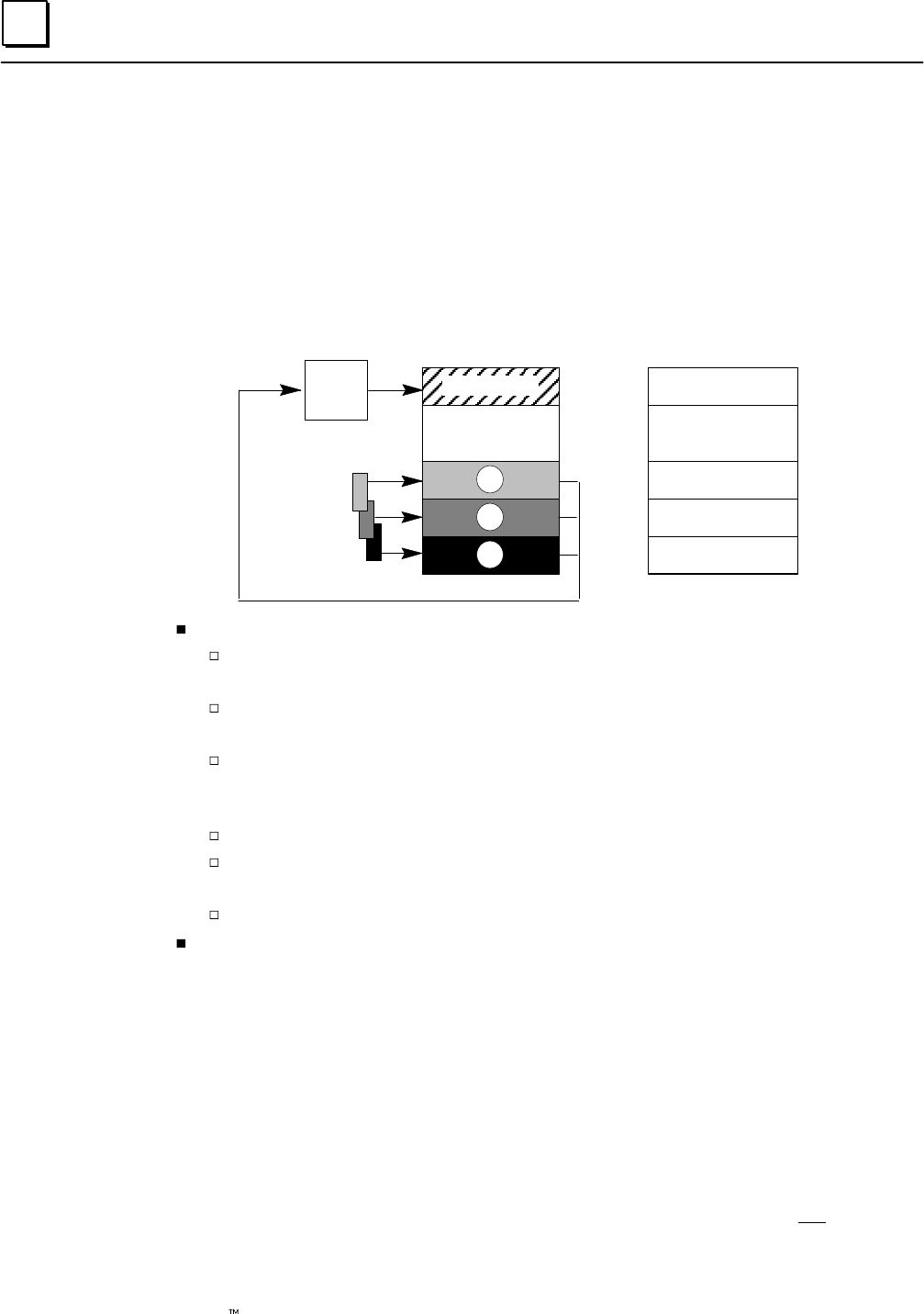
5
5-28 Genius Modular Redundancy Flexible Triple Modular Redundant (TMR) System
User’s Manual –March 1995 GFK-0787B
Analog Fault and Alarm Contacts for GMR
The fault, high alarm and low alarm contacts of non-voted analog inputs and outputs are not
affected by GMR analog I/O processing.
Fault Contacts for Analog Inputs
As with discrete inputs, voted analog inputs have fault contacts associated with both the
raw data inputs and the corresponding voted inputs. Non-voted analog inputs also have
associated fault contacts. (For more information about fault contacts, see page 7-21.)
Analog Input Table
Voted Inputs
Non-voted Inputs
Input
Voting
Logic
Bus A inputs A
B
C
Bus B inputs
Bus C inputs
Conditions that Cause these
Fault Contacts to be Set
Any fault (below)
Genius fault
Genius fault
Discrepancy fault
Genius fault
Genius fault
Discrepancy fault
•
•
•
•
•
•
•
•
Discrepancy fault
Genius faults include Loss of Block, plus the following:
Underrange: the input exceeds –32,767 engineering units or –4095 counts. The
block transmits an underrange message and sets the value to its minimum.
Overrange: the input exceeds +32,767 engineering units or +4095 counts. The
block transmits an overrange message and sets the value to its maximum.
Open wire: Used only for 4–20mA inputs. The fault contact is set if the input
current falls below 2mA. Note that a 4 to 20 mA signal to two or more blocks
must be converted to a voltage, in which case Open Wire faults are not detected.
Wiring error
Internal channel fault: an internal channel fault, such as the failure of the A/D
converter. Block output is indeterminate.
Channel shorted: For RTD blocks only. Block output is indeterminate.
Discrepancy fault: the A, B, or C input is subject to voting and is outside the discrepancy
range.
Fault Contacts for Analog Outputs
For analog outputs, a fault contact is set for any Genius fault, including Loss of Block.
Alarm Contacts
For analog data, there are two additional types of diagnostic contacts that can be used in
the application program, the High Alarm and Low Alarm contacts. These contacts
indicate when an analog reference has reached one of its alarm limits. Alarm contacts are
not considered to be fault contacts.
Alarm contacts can be used on a separate bus in a GMR system, but they can not be used
on any parts of the system that are included in the GMR configuration.
6section level 1 1
figure bi level 1
table_big level 1
6-1
GFK-0787B
Chapter 6Configuration
This chapter describes configuration for a GMR system:
Configuration Overview
The Basic Steps of Configuration
Using the GMR Configuration Software
Getting Started
Creating/Selecting a File
System Configuration Screen
Autotest Interval
CPU Configuration
I/O Limits
Initialization Data
Fault Actions
Genius Bus Controller Group Configuration
Configuring the Input Subsystem for a Bus Controller Group
Configuring the Output Subsystem for a Bus Controller Group
Completing the Logicmaster 90 Configuration
Configuring Bus Controllers
Creating and Copying the PLC Configuration
Logicmaster Configuration Summary
Configuring Genius I/O Blocks
Editing the Reference Addresses
Copying Configurations
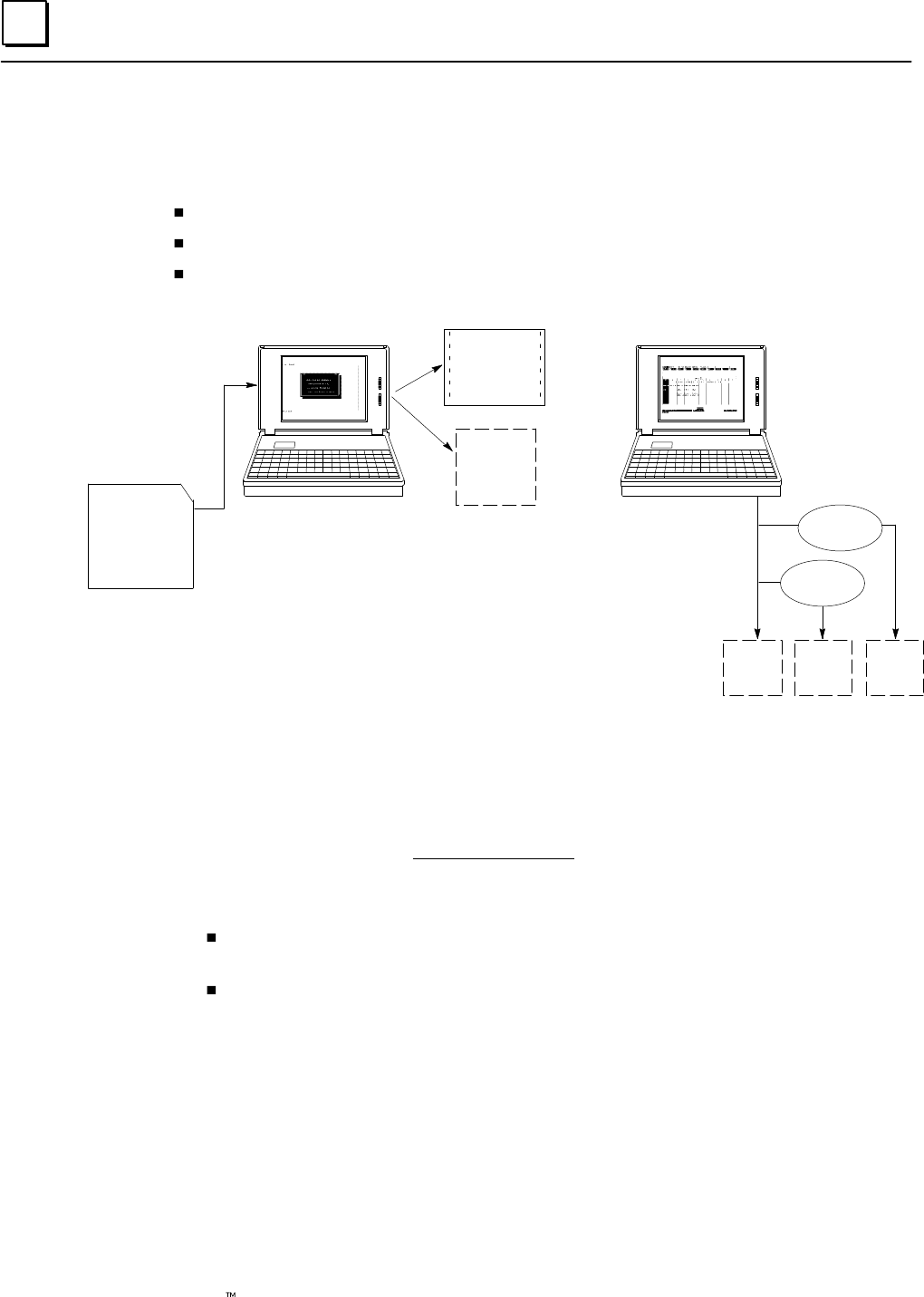
6
6-2 Genius Modular Redundancy Flexible Triple Modular Redundant (TMR) System
User’s Manual – March 1995 GFK-0787B
Configuration Overview
In a GMR system, there are three basic configuration steps:
Completing the GMR configuration using the GMR configuration software.
Configuring the Series 90-70 PLCs.
Configuring the Genius blocks in the system (not shown below).
CONFIG.EXE
GMRxxyy
Download utilities
GMR CONFIGURATION
GMR
Configuration
Printout
G_M_R10
Program
Block
LM90 CONFIGURATION
CONFIGBCONFIGA CONFIGC
GMR
Diskette
LM90
Copy Folder
LM90
Copy Folder
The basic configuration steps are described below.
The Basic Steps of Configuration
1. Complete the GMR configuration. This information is the same for the redundant
PLCs – there is only one GMR configuration needed for the system.
GMR configuration sets up the parameters that will be used by the system, including
reference addresses. The GMR configuration produces:
A printout of the GMR Configuration. Use it as a reference during subsequent
programming and configuration.
A program block named G_M_R10. This is later added to (imported into) the
application program.
2. Create a Logicmaster configuration for each PLC. The easiest way to do that is to:
A. Create a Folder for PLC A, PLC B, and PLC C.
B. Select to the folder for PLC A. With the GMR configuration printout as a
reference, complete its Logicmaster configuration.
C. Use the Copy Folder feature of the Logicmaster 90 programming software to
copy the configuration of PLC A to the folders for PLC B and PLC C. To do this:
(1) From the Logicmaster configuration software, return to the Logicmaster
programming software. Select the Program Folder functions.
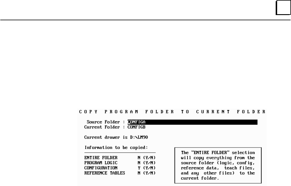
6
6-3GFK-0787B Chapter 6 Configuration
(2) In the Program Folder functions menu, select F1 ... Select/Create a Program
Folder. On the Select/Create screen, select the folder for the second PLC (for
example CONFIGB) as the current folder.
(3) In the Program Folder functions menu, select F10, Copy Contents of
Program Folder to Current Program Folder. On the Copy Folder screen:
(a) For Source Folder, enter the name of the folder containing the
configuration of PLC A (for example, CONFIGA).
(b) For Information to be copied: set only Configuration to yes.
D. If there are three PLCs, repeat this for the other PLC.
E. Return to Logicmaster configuration then edit the configurations for PLC B and
PLC C as necessary. For example, change the bus controller serial bus addresses
and Global Data send and receive addresses.
3. Also, complete the Genius block configuration. Genius block configuration sets up
the operating characteristics of each block in the GMR system.
Basic configuration steps for Genius blocks are the same as for a non–redundant
system. Instructions for completing configuration are detailed in the Genius I/O
Blocks User’s Manual. This chapter gives additional details needed to configure blocks
for use in a GMR system.

6
6-4 Genius Modular Redundancy Flexible Triple Modular Redundant (TMR) System
User’s Manual – March 1995 GFK-0787B
Using the GMR Configuration Software
The GMR Configuration Software is used to enter data needed by the GMR program
software.
Autotest interval
CPU type for the system
I/O limits for the system
initialization data for the system
fault actions for the system
all GBC (bus controller) groups, with all Genius I/O blocks that will use GMR
features
The GMR Configuration Software is not part of the Logicmaster 90 software package. It
is a separate utility that operates on an IBM PC or compatible computer. It runs under
DOS. Either a keyboard or mouse can be used for making entries.
After all the necessary configuration entries have been made, the data is added to the
GMR system software. The GMR system software is provided as a Logicmaster 90
Program Folder, to which the application program is then added.
To assure matching the entries made with the GMR Configuration Software to
corresponding entries made during Logicmaster 90 configuration and Genius block
configuration, the GMR configuration data should be printed out and used as a
reference.
The GMR software requires that:
all PLCs have the same number of bus controllers in the same positions (not
including “non-GMR” bus controllers).
all PLCs are connected to the same “GMR” Genius busses.
Genius busses used for either I/O or communications that are not common to all PLCs in
the system, or that do not use bus addresses as described above must not be included in
the GMR configuration.
GMR Configuration Software Revision and Checksum
The system monitors the checksums of both the configuration data and the application
program, including the GMR software modules. As part of the GMR configuration, you
can select whether to permit online changes. If online changes are permitted, a
configuration mismatch will not stop the PLC. If online changes are not permitted, a
configuration mismatch will stop the PLC. The table on page 4-3 shows in detail what
happens if a configuration mismatch is detected.
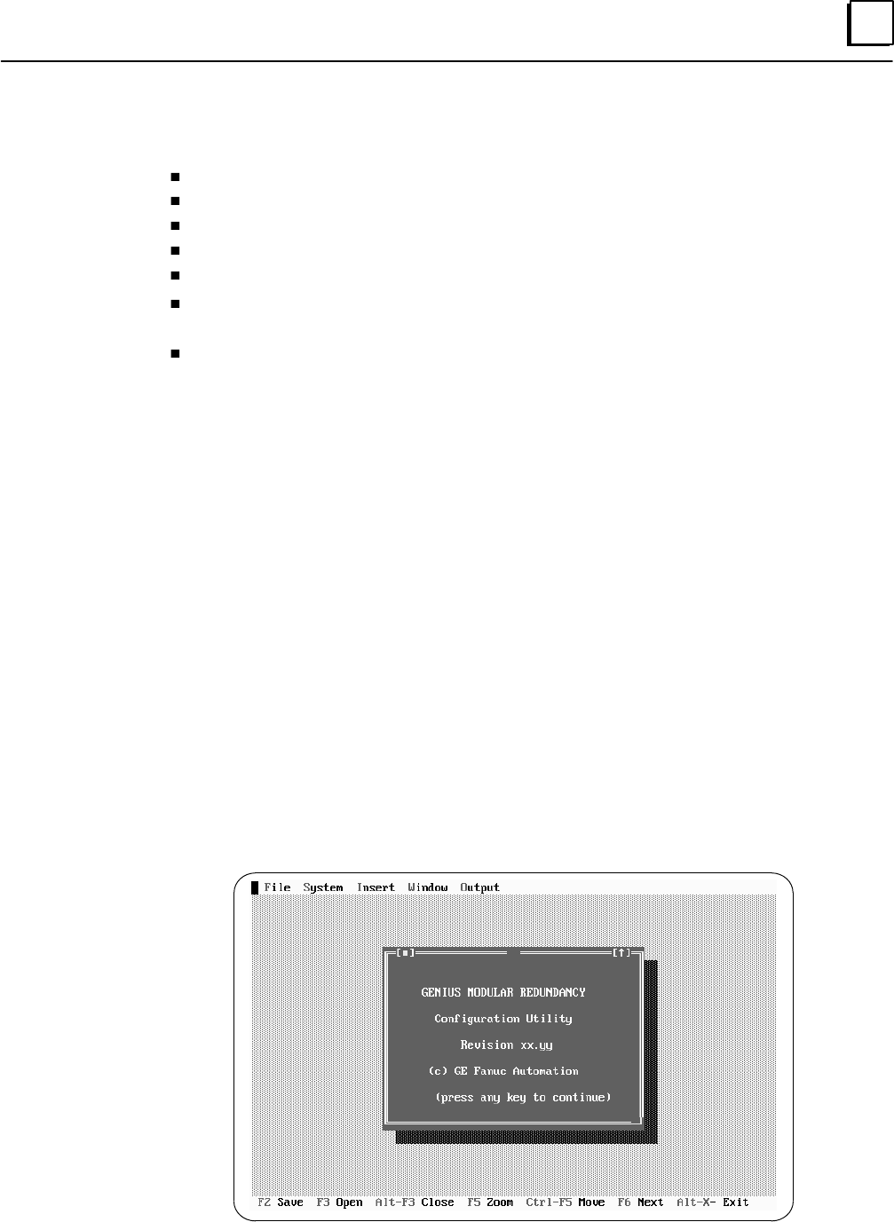
6
6-5GFK-0787B Chapter 6 Configuration
Getting Started
To complete the configuration, you will need to provide the following information:
the CPU type (788 or 789)
the register memory table size.
the Analog Input table size.
the CPU Watchdog timer value.
I/O block serial bus addresses.
I/O block “logical” (%Q) and “voted” (%I and %AI) addresses to be used in the
application program.
Bus controller rack and slot locations.
The GMR Configuration Software will supply default values for these selections. However,
the defaults may not be appropriate for your application. Before beginning, decide on entries
for the items listed above. During configuration, change any defaults that are not suitable.
Installing the Configuration Software
The GMR Configuration Software can be run directly from diskette, or copied to a hard drive.
Operation from a hard drive is more efficient.
To copy the GMR Configuration Software to a backup disk or to the hard drive of a
personal computer on which it will be run, copy all of the files listed below from the
CONFIG subdirectory of your Master GMR software disk.
CONFIG.EXE
G_M_R10.16K
G_M_R10.32K
G_M_R10.48K
G_M_R10.64K
If you are using a mouse with the configuration utility, you also need to install any
necessary mouse driver on your computer.
When you are ready to begin using the software, at the DOS prompt type:
config <retur n>.
The following screen appears:
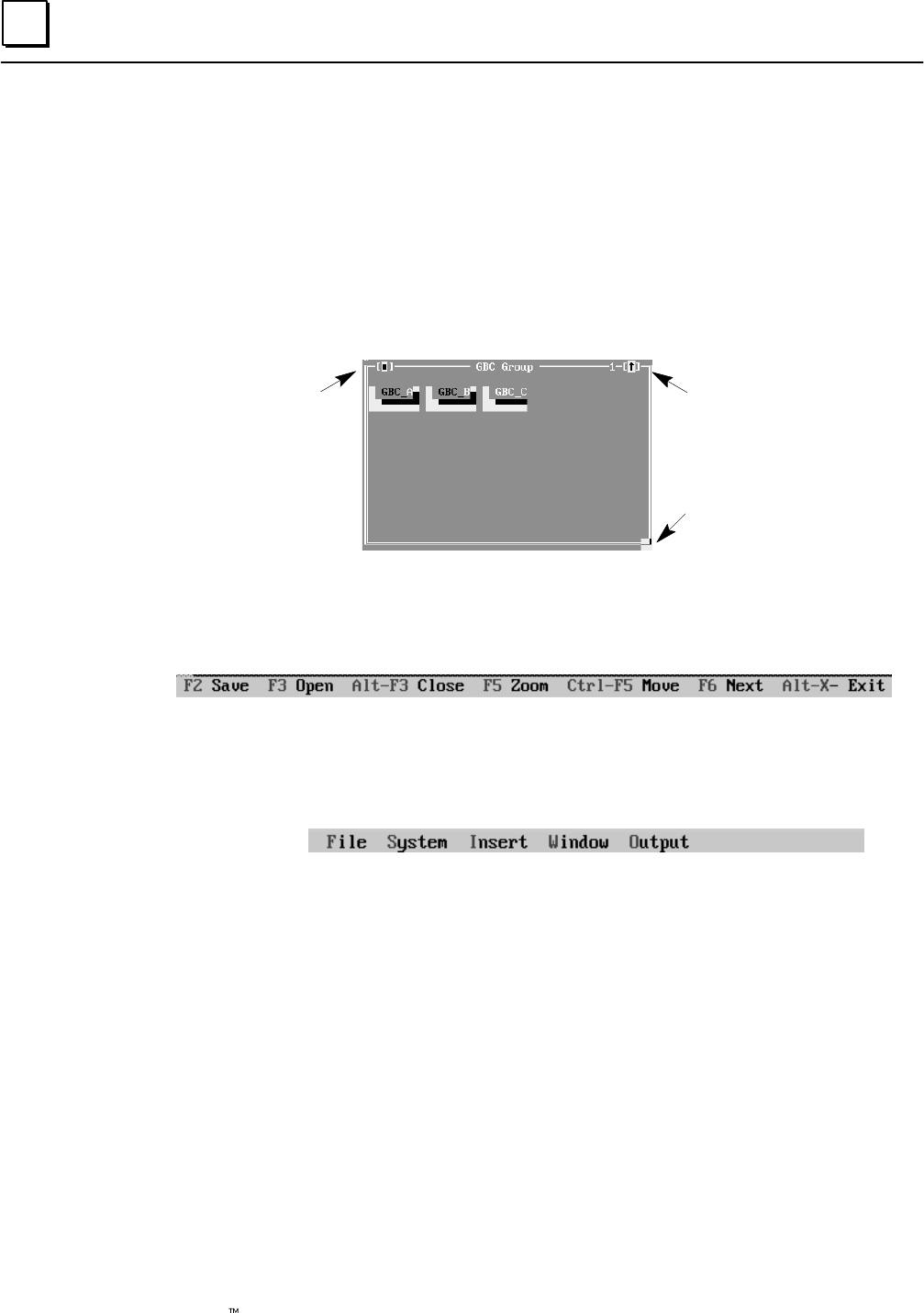
6
6-6 Genius Modular Redundancy Flexible Triple Modular Redundant (TMR) System
User’s Manual – March 1995 GFK-0787B
Mouse and Keyboard Guide for the Configuration Software
Either a mouse or keyboard can be used with the GMR Configuration Software. It is
easiest to use a mouse.
Using a Mouse
When using a mouse, simply move to the item you want to select, and click on it.
Some windows can be closed, zoomed, or resized using a mouse. Look for the symbols
illustrated below:
Click here to
zoom window
Click and drag here to
resize window
Click here to
close window
Using a Keyboard
When making selections and entries from a keyboard, refer to the special key
assignments shown at the bottom of the configuration screen:
Additional keyboard functions are described below.
Alt–(letter) Press the Alt key then the highlighted letter key to select one of the
functions displayed at the top of the configuration screen:
Save (F2) Use the F2 key to save a configuration.
Open (F3) Use the F3 key to open a previously-saved configuration.
Close (Alt/F3) Use the Alt/F3 pair only if you want to close an open configuration
without saving it. (NOTE: No prompt will appear)
Zoom (F5) Use the F5 key to enlarge a configuration window, or to return a
window to its original size.
Move (Ctl/F5) Use the Ctl/F5 pair to move a configuration window on the screen. The
window color changes to show that is in a movable state. Use the cursor,
Home, End, PgUp or PgDn keys to move the window. When it is
positioned where you want it, press the Return (enter) key.
Next (F6) Use the F6 key to move from one window to the next.
Exit (Alt/X) Use the Alt/X pair to exit the GMR Configuration Software. NOTE: if the
configuration is not saved, it will be lost.
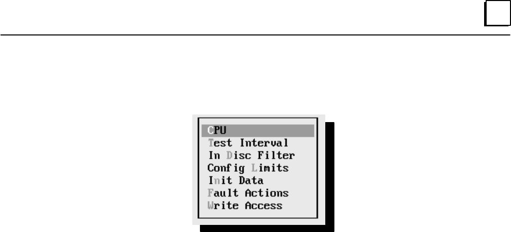
6
6-7GFK-0787B Chapter 6 Configuration
There are two basic ways to select a menu item from the keyboard:
A. pressing the letter key that corresponds to the highlighted letter on the display (for
example, the letter “c” in CPU, below.
B. moving the cursor to that item (using the cursor keys) and pressing Return (enter).

6
6-8 Genius Modular Redundancy Flexible Triple Modular Redundant (TMR) System
User’s Manual – March 1995 GFK-0787B
GMR Configuration Summary
GMR configuration is described in detail on the following pages. The basic steps are:
1. Select File to create a New System configuration
2. In the System menu, create the CPU configuration
CPU Type (788 / 789)
Number of CPUs (1 – 3)
Watchdog timer (must match PLC configuration)
Enable or disable online programming.
Simplex shutdown (enable/disable)
Timeout (0 – 65535 seconds)
Select [O]K or [C]ancel to quit the CPU Configuration window
3. In the System menu, select Autotest Interval and Register
4. In the System menu, select Input Discrepancy Filter Time
5. In the System menu, specify the I/O Configuration Limits
Number of Voted Discrete Input Groups for that GBC group
Number of Voted Discrete Output Groups for that GBC group
Number of Analog Input Groups for that GBC group
Number of words of %AI memory (must match PLC configuration)
Number of registers of %R memory (must match PLC configuration)
Select [O]K or [C]ancel to quit the I/O Config window
6. In the System menu, specify the Initialization Data
Rack and slot locations of the two bus controllers that will be exchanging global data
%R and %M references and lengths for startup initialization data
Select [O]K or [C]ancel to quit the Initialize Data window
7. In the System menu, specify the initialization Fault Actions
Data fault (diagnostic or fatal)
System fault (diagnostic or fatal)
Select [O]K or [C]ancel to quit the Fault Actions window.
8. In the System menu, specify Write Access.

6
6-9GFK-0787B Chapter 6 Configuration
9. [Insert] the first GBC (bus controller) group
A. Select each bus controller in the group (GBC_A, GBC_B, GBC_C).
(1) Specify a rack and slot location
(2) Select [OK] or [C]ancel to quit the Rack/Slot window
B. Configure all the input and output block groups for the GBC group.
(1) [Insert] each Input block group. For each Input block group:
(a) Select the group type (triplex, duplex, simplex, discrete, analog)
(b) Configure the Input block group:
Enter an ID, starting reference address, serial bus address
Select Autotest and specify each input to be autotested and Test
Type for the block group (Sync or Async)
Select [O]K or [C]ancel to quit the Autotest window
Select VoteAdapt and specify each input for vote adaptation
Select the Duplex state (0 or 1), Default state (0/1/hold last), and Hot
Standby mode for any outputs on the block group
Select [O]K or [C]ancel to quit the VoteAdapt window
(2) [Insert] each Output block group. For each Output block group:
(a) Select the group type (16 point or 32 point)
(b) Configure the Output block group:
Enter an ID, starting reference address, serial bus address
Select Autotest and specify each output to be autotested and its
normal state.
Select [O]K or [C]ancel to quit the Autotest window.
Select Options and specify the bus and bus address for the 4th block
Select [O]K or [C]ancel to quit the Options window.
10. [Insert] any additional GMR bus controller groups in the same PLC(s). Configure
each additional bus controller group as described in step 6.
11. Save the configuration. This creates a file with the filename extension .SAV in the
selected directory (by default this is the same directory where the GMR
CONFIG.EXE software is located).
12. With the configuration file still present in the computer’s RAM memory, create the
GMR configuration output file. Select Output, then select Write Configuration
from the Output menu. This creates an output file with the filename G_M_R10.EXE.
This file is stored in the currently-selected directory.
13. Print out the configuration. Select Output, then select Print Out from the Output
menu.
14. Import the configuration into your application folder as described on page 6-46.
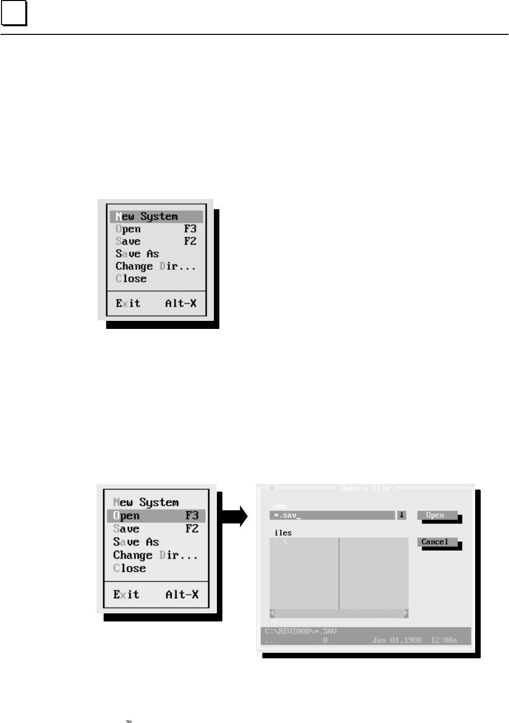
6
6-10 Genius Modular Redundancy Flexible Triple Modular Redundant (TMR) System
User’s Manual – March 1995 GFK-0787B
Creating/Selecting a File
To create a new configuration, or begin editing an existing file, select File. (If you are
using a mouse, click on “File” in the upper left corner of the screen. If you are making
keyboard entries, type Alt/F.)
You can now start a new configuration or open an existing configuration. From the same
screen, you can also save a file with the same name or with a new name, close a file, or
exit the GMR Configuration Software:
Start new configuration New System (N or Enter)
Open previously-saved configuration Open (O or F3)
Save a configuration Save (S or F2)
Save and Rename Save As (A)
Change directory Change Dir (D)
Close without saving Close (C)
Exit Quit configuration (X)
In a menu, to select an item with a mouse, move the cursor to it and click. To select a
menu item from the keyboard, use the cursor keys to move the cursor, and press Enter
(Return) or press the highlighted letter key (without the ALT key).
Opening a Previously-Saved Configuration File
The GMR configuration software stores files with the filename you choose, and the
extension .SAV. For example, CONFIG1.SAV. If you want to view, edit, write, or print a
previously-saved configuration file, select Open (F3) from the File menu.
Select Open to open the file.
This loads the selected file into the computer’s RAM memory.

6
6-11GFK-0787B Chapter 6 Configuration
Saving a Configuration File
Select Save (F2) to save the configuration file presently in RAM memory (the one
displayed on your computer screen). This function saves the file with the selected name,
overwriting the previous version. If you want to specify another filename (for example,
to create a new version of a configuration file without writing over the old one, select
Save As instead. The software gives each saved file the filename extension .SAV.
During a file editing session, the first time you select Save, the software automatically
displays the Save As screen so you can select a name for the file.
GMR configuration files are stored in the currently-selected directory. By default, this is
the directory in which the GMR configuration utility software was installed, but you can
change it before saving the file, as explained on the next page.
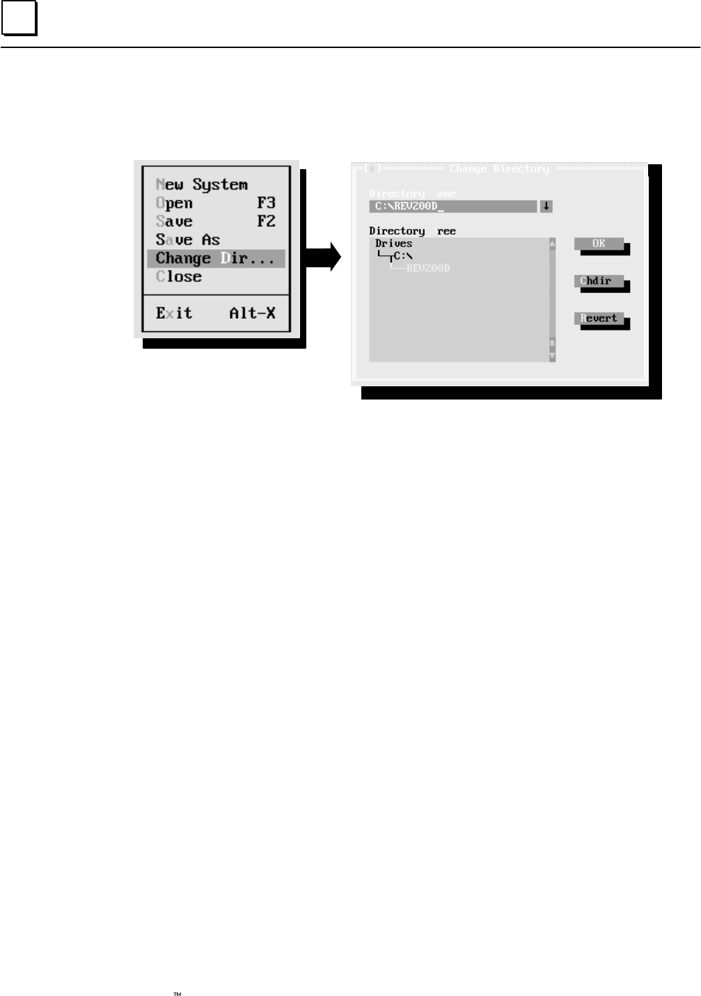
6
6-12 Genius Modular Redundancy Flexible Triple Modular Redundant (TMR) System
User’s Manual – March 1995 GFK-0787B
Changing to Another Directory
Use the Change Directory function if you want to access another directory. (Additional
directories must be created in DOS.)
Select Chdir to change the
directory.
Select Revert to return to the
previous directory.
If you are using a mouse, you can click on the “elevator” bar at the right of the Directory
Tree to scroll through the directory structure.
By default, the GMR configuration software uses the directory in which the GMR
configuration utility was installed to save your configuration file(s). However, can use
other directories if you prefer.
If you have made changes in this window but want to exit without saving your changes,
you can click on the “close” button in the upper left corner of the window.
Closing a Configuration File without Saving It
If you want to exit a configuration without saving it, select Close from the File menu.
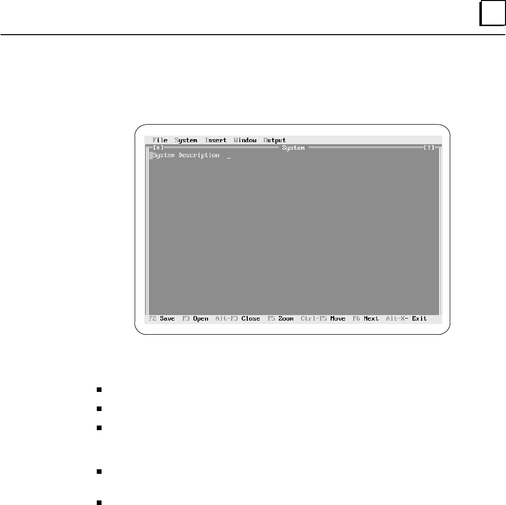
6
6-13GFK-0787B Chapter 6 Configuration
Starting a New Configuration
When you select New System from the File menu using the mouse, or using the Enter
(Return) key, the System screen appears:
From this screen, you can:
return to the file-handling functions (click on File or press ALT/F)
change a system parameter (click on System or press ALT/S)
add a configuration item to the current file (click on Insert or press ALT/I. When the
Configuration menu appears, click on the item to insert, or press the highlighted
letter key).
print out a copy of the configuration (click on Output or press ALT/O. When the
Output menu appears, click on Print Out or press [P].).
create the configuration output file (click on Output or press ALT/O. When the
Output menu appears, click on Write Config or press [W].)
Additional key functions are displayed on the bottom of the screen.
Entering a System Description
At the top of the screen, enter a description of up to 40 characters. This information will
appear when you print out the configuration. It is also saved in the G_M_R10 file and
can be used to determine what configuration is used in the system with the Report
function (%M12262).
Closing and Deleting the System Configuration File
If you want to quit from this window without creating a file or saving any entries, you
can click on the “close button” in the upper left corner of the screen.

6
6-14 Genius Modular Redundancy Flexible Triple Modular Redundant (TMR) System
User’s Manual – March 1995 GFK-0787B
GMR Configuration Selections
When you select System, the following menu appears
CPU configuration
Select autotesting interval
Input Discrepancy Filter
Set configuration limits
Select Initialize data areas
Select fault actions
Configure memory write access
Create the configuration by selecting items from the menu, then completing entries on the
screens that appear. Instructions for completing these screens begin on the next page.
To display the configuration screen for the currently-highlighted menu selection, click on
it with the mouse or press the Enter key.
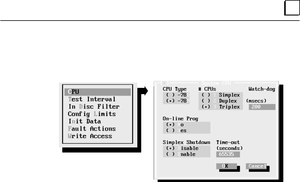
6
6-15GFK-0787B Chapter 6 Configuration
CPU Configuration
Complete the entries on the CPU Configuration menu. The defaults are indicated with
dots in the parentheses, as shown below. If a default selection is correct for your system,
you don’t need to edit that item.
Specify whether the CPU is model IC697CPU788 or 798.
Specify whether Online programming will be permitted. If this item is
set to Yes, online run mode stores, single word online changes, or block
edits can be made without shutting down the PLCs. See page 7-37 for
information about online changes.
Note: online changes are intended for system debug and commissioning
only.
Specify 1, 2, or 3 CPUs in the GMR system.
If Simplex Shutdown is enabled, a PLC will shut down if it determines
that it is the only PLC still operating. The timeout period before it shuts
down is configured as the next item. When the PLC shuts down the
system, it sets its outputs to their default state or last state, as configured
for each block.
If Simplex Shutdown is enabled, this selects the timeout period. The
timeout period may be 0 to 65535 seconds (18.2 hours).
This must be the same value as the watchdog timer in the Logicmaster
90-70 CPU Configuration. The default is 200mS.
Exiting the Window
When you complete this screen, select OK to return to the System screen. When you
select OK, your entries are saved in RAM and the window disappears.
If you want to exit the window and reset all fields to their previous content, select Close or
Cancel instead.
CPU Type
On Line Prog
# CPUs
Simplex
Shutdown
Timeout
Watchdog
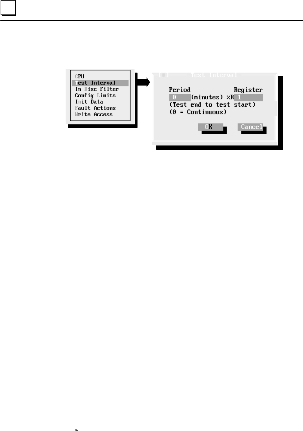
6
6-16 Genius Modular Redundancy Flexible Triple Modular Redundant (TMR) System
User’s Manual – March 1995 GFK-0787B
Test Interval
First, configure the interval for autotesting, and a register where this interval should be
stored.
On this screen, enter:
Specify an autotest interval of 1 to 65535 minutes. This becomes the time
interval the system will wait between autotests of the I/O subsystem.
Specify a %R register. When the system is started and goes through
initialization, this register is initialized to the period configured (above).
The GMR system reads this register to determine the autotest interval.
The contents of this register can be modified by the application program
or changed using the Logicmaster programming software to alter the
autotest interval (if desired) without reconfiguring the system.
See the Programming chapter for information about %R memory usage
in a GMR system.
When you have completed this screen, select OK to return to the System screen.
Exiting the Window
When you select OK, your entries are saved and the window disappears. If you want to
exit the window and reset all fields to their previous content, select Close or Cancel instead.
Period
Register
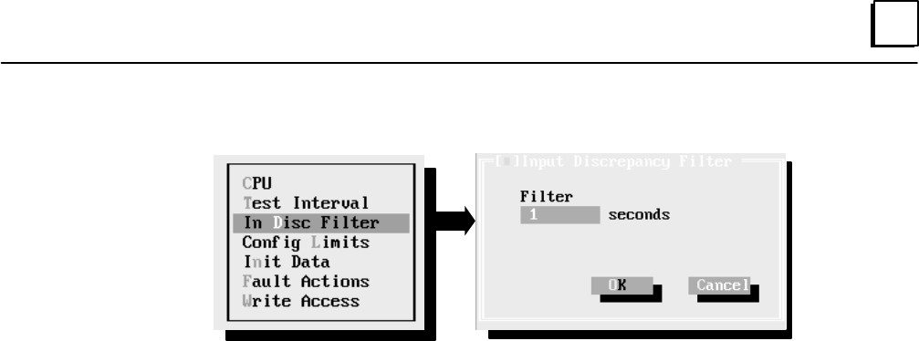
6
6-17GFK-0787B Chapter 6 Configuration
Input Discrepancy Filter
On this screen, enter the input discrepancy filter time in seconds. This is the amount of
time, in seconds, that a particular input may be discrepant before the CPU places a
message in the I/O Fault Table, and sets the appropriate fault contact for that voted
input. This input discrepancy filter time applies to both discrete and analog inputs. This
time defaults to one second. The range is 1 to 65535 seconds.
Exiting the Window
When you select OK, your entries are saved and the window disappears. If you want to
exit the window and reset all fields to their previous content, select Close or Cancel instead.
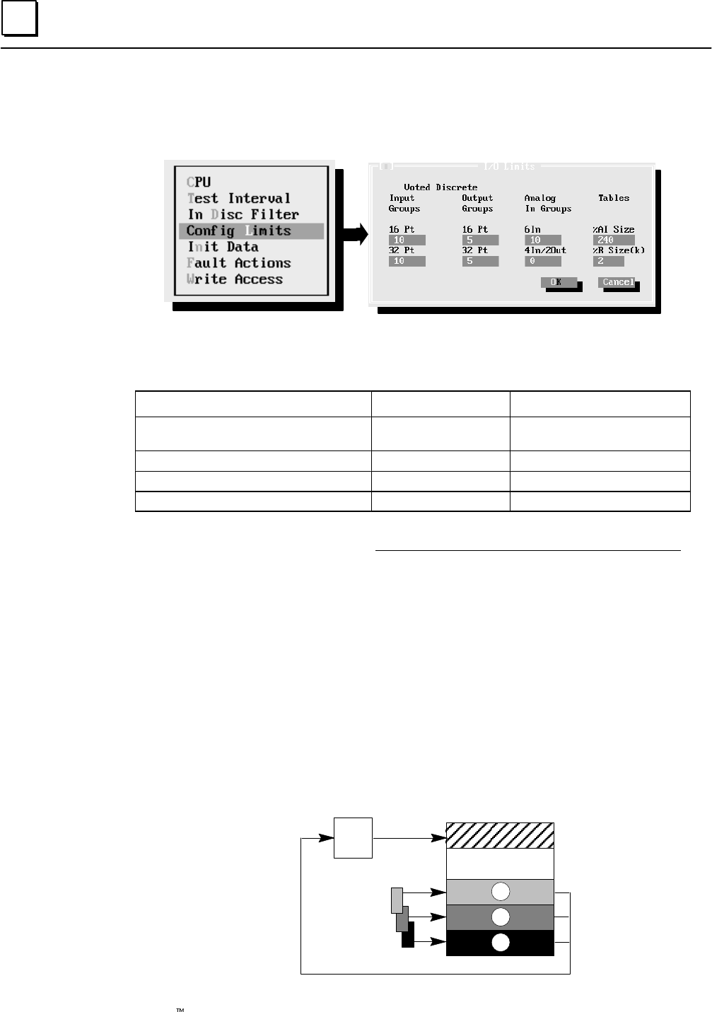
6
6-18 Genius Modular Redundancy Flexible Triple Modular Redundant (TMR) System
User’s Manual – March 1995 GFK-0787B
I/O Limits
Select System again. From the configuration menu, select Config Limits (click the mouse
on that line or cursor down and press Enter).
Entries made on this screen determine how the GMR software allocates memory. The
maximum number of groups that can be configured is 128. Additional parameter limits
for this screen are summarized below.
Item Parameters Comment
Total number of voted digital inputs
and redundant outputs 1...112 (788 CPU)
1...2048 (789 CPU) In increments of 16 or 32
Number of voted analog inputs 1...1024 In increments of 4 or 6
%AI Analog Input Table size 1...8192
%R register table size 1 to 16 Specified in increments of 1K
Enter the number of 16-circuit and 32-circuit discrete input and output
groups in the system (plus any spare groups you may add in the future).
Each input group may consist of 1, 2, or 3 blocks. The GMR software will
assign these voted I/O addresses at the beginning of the I/O tables, and
“raw” data addresses at the end of the I/O tables (similar to the
illustration of analog inputs, below, and discussed in detail in chapter 7).
Enter the number of groups made up of 6-input analog blocks and the
number of groups made up of 4-input (2-output) blocks. Include any
spare groups you may add in the future
Enter the amounts of word memory to be allocated to analog input data
(%AI) and register data (%R). These values must match the
corresponding values configured using Logicmaster 90.
%AI Size: Allow enough %AI memory to accommodate all analog input
data, as explained below. The maximum size is 8192 analog channels (words).
%AI memory is divided into sections:
Voted Inputs
non-voted
Inputs
Input
Voting
Logic
A inputs A
B
C
B inputs
C inputs
%AI0001
Voted
Discrete
Analog
In Groups
Tables
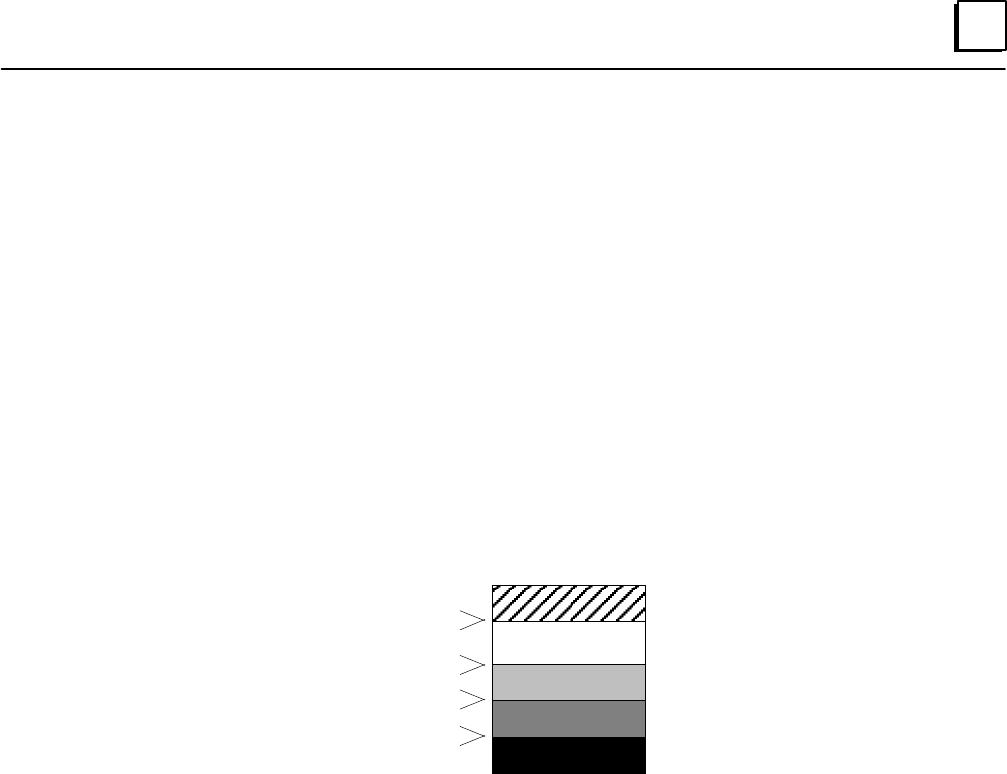
6
6-19GFK-0787B Chapter 6 Configuration
The voted analog references start at %AI0001. The size of the voted
analog input area is determined by the number of voted analog inputs
including spares.
Physical input data from analog block groups is located at the end of the
Analog Input Table, in the areas labelled A, B, and C in the preceding
illustration. Each of these areas is equal in length to the number of voted
inputs at the beginning of the table.
Unused portions of the Analog Input Table may be used for simplex
inputs.
Example
The following illustration shows an example Analog Input memory
configuration for a system with multiple GMR busses. There are a total
of 30 input groups having 6 inputs each, and 19 input groups having 4
inputs each. So the total number of voted inputs is:
( 6inputs X 30 groups) + ( 4 inputs X 19 groups)=256 voted inputs
The simplex inputs could then begin at %AI0257.
Voted Inputs
Simplex Inputs
A inputs
B inputs
C inputs
%AI0001
%AI0256
%AI0257
%AI7424
%AI7525
%AI7680
%AI7681
%I7936
%AI7937
%AI8192
Data from an analog block occupies either 4 or 6 input words,
depending upon the number of analog input channels on the block.
%R Size: In addition to any other specific %R memory required for the
application program, there must be %R memory available to the GMR
software for bus controller data and communications data.
To configure the correct amount of %R memory for the application, use
this worksheet:
_________ %R Initialization Data
+ _________ %M Initialization Data (number of 16-bit words)
+ _________ %R data needed for the application
+ _________ %R spare
+ 320 words Global Data
+ _________ (Number of GMR Bus Controllers in CPU x 66 registers)*
= _________ Total Words of Register Data
Configure the next higher 1K increment.
*For more information, please see chapter 7.
Exiting the Window
When you have completed this screen, select OK to return to the System screen. When
you select OK, your entries are saved and the window disappears. If you want to exit the
window and reset all fields to their previous content, select Close or Cancel instead.
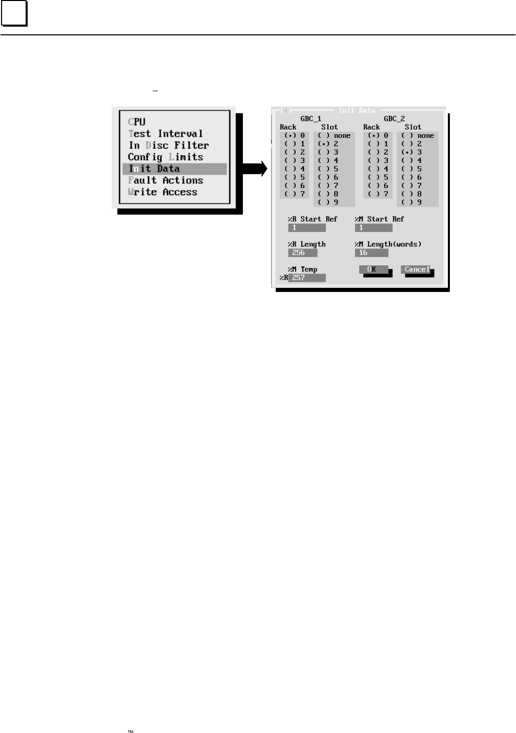
6
6-20 Genius Modular Redundancy Flexible Triple Modular Redundant (TMR) System
User’s Manual – March 1995 GFK-0787B
Initialize Data
Next, select System to configure the Initialization Data.
Initialization data, as explained in the PLC Subsystem chapter of this book, is exchanged
between PLCs during startup. It consists of data such as timers and counters and latched logic
states.
It is important to be sure that the memory assignments you make here do not directly
conflict with %R and %M memory used in the application program or required
elsewhere by the GMR software. For more information about memory requirements for
GMR, refer to the Programming chapter.
Enter the rack and slot location for the two bus controllers in the GMR
group that will be exchanging global data. These can be any two bus
controllers in the system, but they must be at the same rack and slot
location in each PLC.
If the PLCs will exchange %M data during startup, enter a starting
reference and length in words. (If the PLCs will not exchange %M data
at startup, enter 0 in the %M length field).
If another PLC is already online during initialization, the initializing PLC
will place %M data received from that PLC into its own %M memory in
this location. If both other PLCs are already online, the initializing PLC
will place data from the PLC with the highest serial bus address into this
%M location.
This %M location can be the same as the %M memory used in the
application program. It is a temporary storage area that is only used at
startup, to store a copy of another PLC’s %M data.
It must begin on a byte boundary (multiple of 8, +1). By default, this
starting reference is %M0001. The default length (next field) is 16.
Enter the length in words for the %M temporary storage area. It should
equal the quantity (in words) of %M memory used in the application
program.
GBC_1
GBC_2
%M Start Ref
%M Length
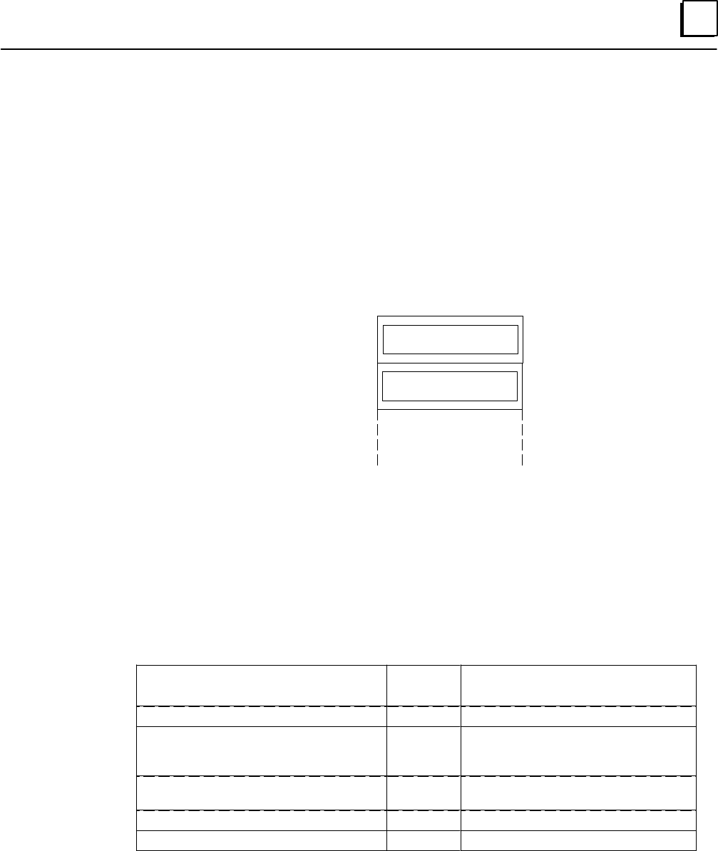
6
6-21GFK-0787B Chapter 6 Configuration
If, when the PLC is starting up, the other two PLCs are already online,
%M data from the second online PLC (the one with the lower serial bus
address) is also received by the initializing PLC.
In the %R Temp Ref field, enter a starting reference in %R memory to
receive %M data from the second online PLC. (In this field, the %M
refers to the type of data being received. In the two fields on the
previous page, it refers both to the type of data being received and the
memory location where it will be placed).
Notice that this field shows a initial starting reference of 257. By default,
the %M data from the second online PLC is stored directly after the %R
data from the first:
%R0001
%R0256
%R0257
%R0272*
%R Initialization from
First Online PLC
%M Initialization from
Second Online PLC
* if following the previous example
If the PLCs will exchange %R data during startup, enter a starting
reference and length in words. (If the PLCs will not exchange %R data
at startup, enter 0 in the %R length field. Enter an starting reference for
the %R data to be received from the other PLC(s) online during CPU
initialization. By default, this starting reference is %R0001.
Enter a length in words for the %R data. The amount needed depends on
%R memory usage in the application program. The default length is 256.
The table below lists total limits for these items.
Item Parame-
ters Comment
Starting reference for %M init. data 1 to 12224 Must be on 8-bit boundaries.
Length of %M initialization data 0 to 764 Length in words.
(start ref +16 X length)<=12288
0 if no %M init. data
Starting reference for %M temporary ini-
tialization data (to be stored in%R) 0 to 16384 0 if length of %M init. data (above) is 0.
Starting reference for %R init. data 1 to 16384
Length of %R initialization data 0 to 4096 0 if no %R init. data
Exiting the Window
When you have completed this screen, select OK to return to the System screen. When
you select OK, your entries are saved and the window disappears.
If you want to exit the window and reset all fields to their previous content, select Close or
Cancel instead.
%R Temp Ref
%R Start Ref
%R Length
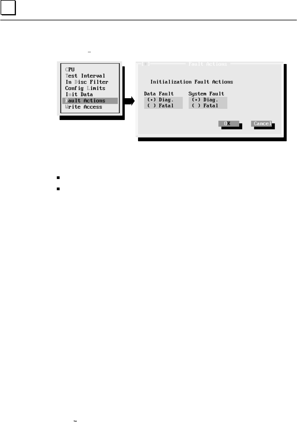
6
6-22 Genius Modular Redundancy Flexible Triple Modular Redundant (TMR) System
User’s Manual – March 1995 GFK-0787B
Fault Actions
Next, select System to configure Initialization Fault Actions:
These entries determine how the GMR software will respond to either of the following
faults during CPU initialization:
an initialization data error (data fault)
a hardware fault (system fault)
For each type, select whether the GMR software will:
( ) Halt the PLC (fatal)
( ) Allow the PLC to continue operating (diagnostic) and set the appropriate %M status
flag.
%M12232 Init Miscompare at startup
%M12234 System fault at startup
Exiting the Window
When you have completed this screen, select OK to return to the System screen. When
you select OK, your entries are saved and the window disappears.
If you want to exit the window and reset all fields to their previous content, select Close or
Cancel instead.
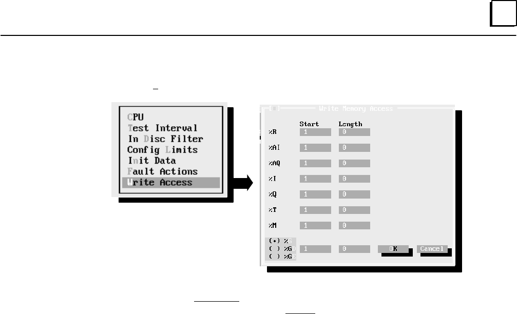
6
6-23GFK-0787B Chapter 6 Configuration
Write Access
Next, select System to configure Write Access:
On this screen, you can configure starting addresses and lengths for any memory areas
to which data can be written to through a CMM, PCM, or Ethernet Communications
Module. These configuration parameters do not prevent write access through Genius
Bus Controllers, the CPU’s built-in port or with serial or parallel Logicmaster 90-70.
The following memory areas can potentially be written to:
%R Registers
%AI Analog Input Table
%AQ Analog Output Table
%I Discrete Input Table
%Q Discrete Output Table
%T Temporary internal reference bits that are not saved through power loss
%M Internal reference bits that are saved through power loss
%G Global Data memory
%GD Global Data memory
%GE Global Data memory
The Start parameter for each memory area is the start of the address range to which
write access will be permitted. It may be from 1 to the maximum table size.
The Length parameter is the length of the address range to which write access will be
permitted. A value of 0 (the default) means the entire contents of that memory type is
write-protected. For %R, %AI, and %AQ memory, length is in units of registers (words).
For discrete (bit) memories: %I, %Q, %T, %M, %G, %GD, and %GE, the starting
reference must be on a byte boundary (1, 9, 17, etc). For these memory types, the length
is in units of points (bits). It must be specified in multiples of 8 bits (8, 16, 24, etc...)
Global Data %GA, %GB, and %GC memories are not available. Those memory areas are
used by the GMR system to exchange data (as explained on page 7-27), and cannot be
accessed directly.
Exiting the Window
When you have completed this screen, select OK to return to the System screen.
When you select OK, your entries are saved and the window disappears. If you want to
exit the window and reset all fields to their previous content, select Close or Cancel instead.
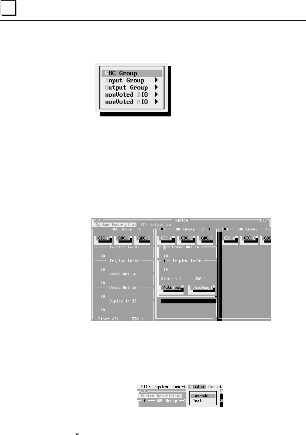
6
6-24 Genius Modular Redundancy Flexible Triple Modular Redundant (TMR) System
User’s Manual – March 1995 GFK-0787B
Adding Bus Controllers and I/O Modules
When you select Insert from the System screen, the following menu appears
Configure Bus Controller groups
Configure Input Group
Configure Output Group
Configure non-voted discrete I/O
Configure non-voted analog I/O
Create the configuration by selecting items from the menu, then completing entries on the
screens that appear. Instructions for completing these screens begin on the next page.
To display the configuration screen for the currently-highlighted menu selection, click on
it with the mouse or press the Enter key.
The Bus Controller and I/O group configuration windows have some additional mouse
or keyboard features not used in other configuration windows.
On the example screen below, three Bus Controller groups have been configured. Group
1 has five input and output block groups. Group 2 has two I/O block groups. No I/O has
yet been configured for Bus Controller Group 3.
On this screen, you can move between Bus Controller groups by clicking the mouse on
the group you want or by pressing the Alt key then entering the number of the Bus
Controller group.
If you want to display all of the I/O group windows as they are shown above, select
Windows, then Cascade from the functions at the top of the screen.
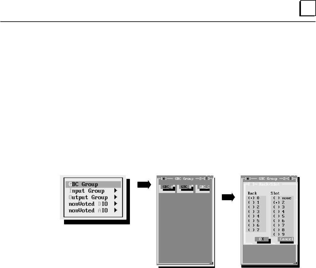
6
6-25GFK-0787B Chapter 6 Configuration
Genius Bus Controller Group Configuration
Note: It is possible that an application may include bus controllers in the PLC racks that
are not part of the GMR system. Do not include non-GMR bus controllers in the GMR
configuration. The only exception to this is a bus controller pair that is used for global data
communications between PLCs. (Other, non-GMR bus controllers are included in the
Logicmaster configuration only).
In each PLC, GMR Bus Controllers must be installed in the same rack and slot locations. The first
default rack and slot locations are:
bus controller “A”: rack 0, slot 2
bus controller “B”: rack 0, slot 3
bus controller “C”: rack 0, slot 4
If those are the actual bus controller rack and slot locations that will be used for this GBC
group, you can use the defaults and skip directly to the next step.
Click the mouse on the GBC Group button, or cursor to it and press the Return key.
This display represents the three bus controllers that would be present in the PLC
system for a triple bus. They are shown as “GBC A, GBC B, and GBC C”. If there are
fewer bus controllers, they can be identified in any combination. For any bus controller
not present, select “none” as the slot.
On the middle window shown above, you can use the Tab key to select bus controller A,
B, or C. Use the space bar key to display the Rack/Slot configuration data for the selected
bus controller.
To configure a bus controller rack/slot location, select GBC_A, GBC_B, or GBC_C, and
press the space bar key. The rack/slot configuration window (shown on the right above)
for that bus controller appears.
By default, bus controller A is specified in rack 0, slot 2, as shown. To edit rack/slot location
choices, use the tab keys to move from field to field. Use the cursor keys to move within a
field. When both the rack and slot locations are correct for the bus controller, select [O]K.
Complete the same steps for other bus controllers in the same group.

6
6-26 Genius Modular Redundancy Flexible Triple Modular Redundant (TMR) System
User’s Manual – March 1995 GFK-0787B
Exiting the Window
Normally, the GBC (Genius Bus Controller) group window remains on the screen, so
you can insert the I/O groups for that bus controller group. (It must be the “active”
window (identified by the double line border) to insert an I/O group into it).
However, if you want to exit the window, and delete the window from your configuration,
click on the Close button in the upper left corner of the window. Be aware that in this
window, and in the windows for I/O blocks and in the System screen window, clicking
on the Close button deletes the window and its content. This is different from operation
of the Close button in windows that are part of the standard GMR default configuration
(for example, the CPU Configuration window), where default entries may be used.
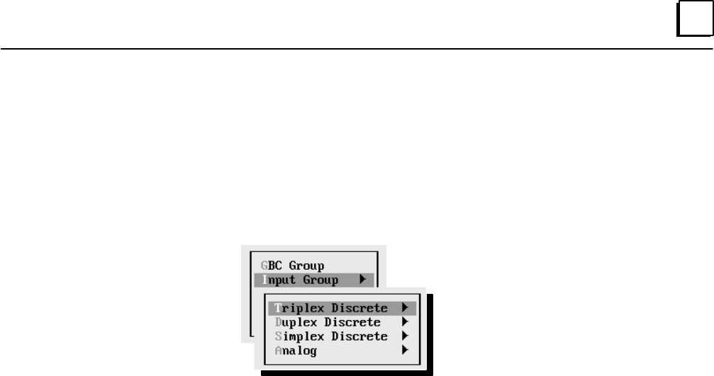
6
6-27GFK-0787B Chapter 6 Configuration
Configuring the Input Subsystem for a Bus Controller Group
With the rack and slot locations for a bus controller group configured, the next step is to
configure the input subsystem for that bus controller group.
Click on Insert or press ALT–I to display the Insert menu. Select Input Group from the
menu by clicking on that item or by pressing [I]. Click on the type of group to insert, or
press its highlighted letter key, or use the cursor keys to select an item then press the
Return key to display a sub-menu of input block types:
From this menu, select and configure the types of input groups in the input subsystem.
Select: To Configure:
triplex discrete each group of three input blocks
duplex discrete each group of two input blocks
simplex discrete each “group” of one input block
analog each group of analog blocks
After you select the group type, additional configuration screens appear for configuring
the GMR features for that group. See the instructions on the following pages.
Exiting a Block Group Window
When you have completed a block group screen, you can continue to configure another
block group.
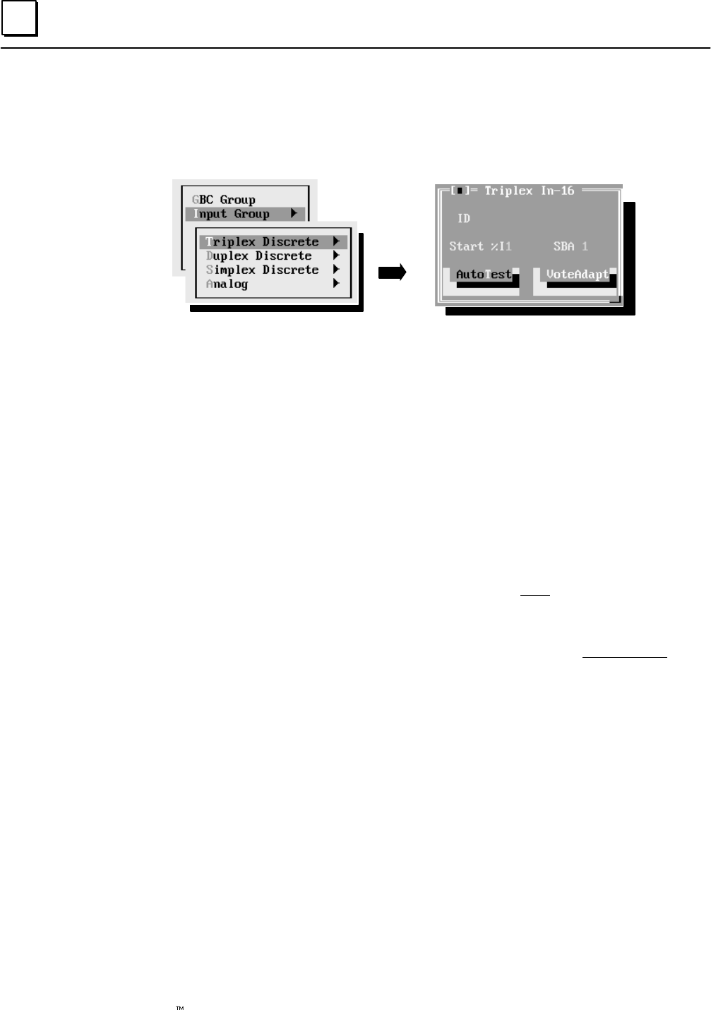
6
6-28 Genius Modular Redundancy Flexible Triple Modular Redundant (TMR) System
User’s Manual – March 1995 GFK-0787B
Configuring a Triplex, Duplex, or Simplex Discrete Input Group
To configure a discrete group, click on that line, or move the cursor there and press the
Return key, or press the highlighted letter key. Then select whether the blocks in the
group are 16-point or 32-point blocks. For example:
A configuration screen like the one shown above right appears. To item on this screen,
use the Tab key or mouse.
Enter a name or a description of up to 12 characters, such as
“in group 3”. This entry is for your information only. It is not used by
the GMR software.
Enter the starting %I Input Table reference for the group. This is the %I
address of the voted input data. The actual %I references used for the
input data from each block are configured using the Logicmaster 90
software. This configuration utility will provide a printout of the addressing
required for Logicmaster 90. The allowable reference ranges are:
0001 to 0112 (788 CPU)
0001 to 2048 (789 CPU)
Duplicate addresses are not allowed within a GBC group. You will not
be permitted to continue until you have entered a unique address.
Enter a serial bus address (also referred to as the “device number”) from
0 to 28. Duplicate bus addresses are also not permitted within a GBC
group. However, each block in the group uses the same serial bus address on its
respective bus.
ID
Start %I
SBA
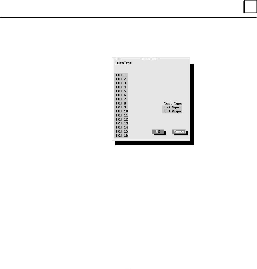
6
6-29GFK-0787B Chapter 6 Configuration
Highlight this item then press the space bar key to display a screen for
setting up Input Autotest and Test Type for individual circuits (screen for
16-circuit blocks shown here).
If input circuits on the blocks in the group should be autotested, circuit
16 (the powerfeed output) must have autotest enabled. If no circuits are
to be autotested, circuit 16 can have autotest disabled, and input devices
can be wired directly to the power source instead of being wired to
circuit 16 (the powerfeed output).
By default, each circuit is set up for autotesting, as shown by the X next
to the circuit number. To turn off autotesting, select that circuit (click on
the circuit or select it using the cursor keys). Press the space bar to
remove the X. Note: For all unused circuits on the blocks, autotest
should be set to off. Also, it is possible for an input block to include I/O
circuits that are not part of the GMR system, and which are not to be
autotested. Be sure to turn autotest off for non-GMR circuits.
Test Type: Select whether the testing should be Synchronous (the
default) or asynchronous.
Asynchronous Autotesting: allows the input autotest to continue
executing on other blocks in a group which are not affected by the fault.
It can be selected if:
A. redundant discrete input devices are used (the power feed outputs
of each block ARE NOT wired together).
B. non-redundant simplex discrete input devices are used with
isolation between blocks.
Synchronous Autotesting: synchronous input autotesting must be
selected if non–redundant simplex discrete input devices are used
without isolation between blocks (I.E. the power feed outputs of each
block ARE wired together). With Synchronous Autotest, Loss of Block
faults or certain autotest faults may prevent the autotest from
continuing to execute for that input block group and thus cause a I/O
shutdown for the inputs in the group. See page 4-18 for more
information.
Auto Test

6
6-30 Genius Modular Redundancy Flexible Triple Modular Redundant (TMR) System
User’s Manual – March 1995 GFK-0787B
1.) Loss of a block within the group. (I.E. any failure which causes the
block to no longer communicate on the Genius Bus such as loss of
power.)
2.) Autotest failure of the power feed output (point Q16) of any of the
blocks in a group.
For discrete output groups there are also two types of faults which
may prevent the output autotest from continuing to execute for that
output group and thus cause an I/O shut down for the outputs in
the group.
1.) Loss of a block within the group. (I.E. any failure which causes the
block to no longer communicate on the Genius Bus such as loss of
power.)
2.) Output autotest failure detected of a type which could potentially
prevent a normally energized output from being tripped off. An
example is the short of a source block output to +24 Vdc.
After completing the selections for Autotest, select OK.
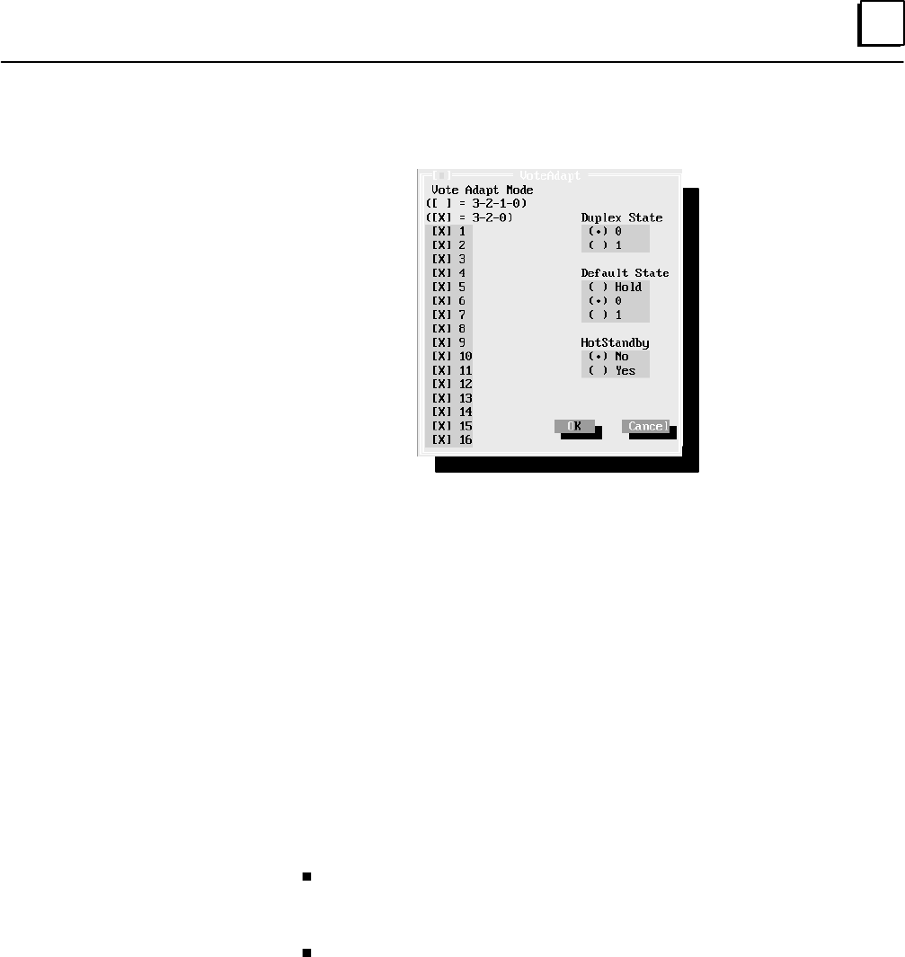
6
6-31GFK-0787B Chapter 6 Configuration
Similarly, select which Voting Adaptation method will be used for each
circuit.
Vote Adapt Mode: Specify the manner in which the PLCs should perform
voting adaptation. During operation, if a failure (discrepancy fault, Autotest
fault, or Genius fault) occurs, the GMR software will reject the faulty data
and perform voting adaptation as configured here.
For a triplex group, if input voting should go from three inputs to two inputs to
one input, select 3–2–1–0. If voting should go from three inputs to two
inputs to the default state, select 3–2–0.
For a duplex group, if input voting should go from two inputs to one input,
select 3–2–1–0. If voting should go from two inputs to the default state,
select 3–2–0.
For a simplex group, select 3–2–1–0.
Duplex State:
For a triplex group, the Duplex State determines the vote type when there
are just two inputs present. Its operation is described on page 4-8.
Using 0 as the Duplex State means that when two I/O blocks
(duplex) are online, the voted input state will be 0 if either input sets
it to 0. It will not be 1 unless both inputs set it to 1.
Similarly, using 1 as the Duplex State means that when two blocks
are online, the voted input state will be 1 if either input sets it to 1. It
will not be 0 unless both of the inputs set it to 0..
For a duplex group, this state is used as the third input in the 2 out of 3 vote.
For a simplex group, this field does not apply.
Vote
Adaptation
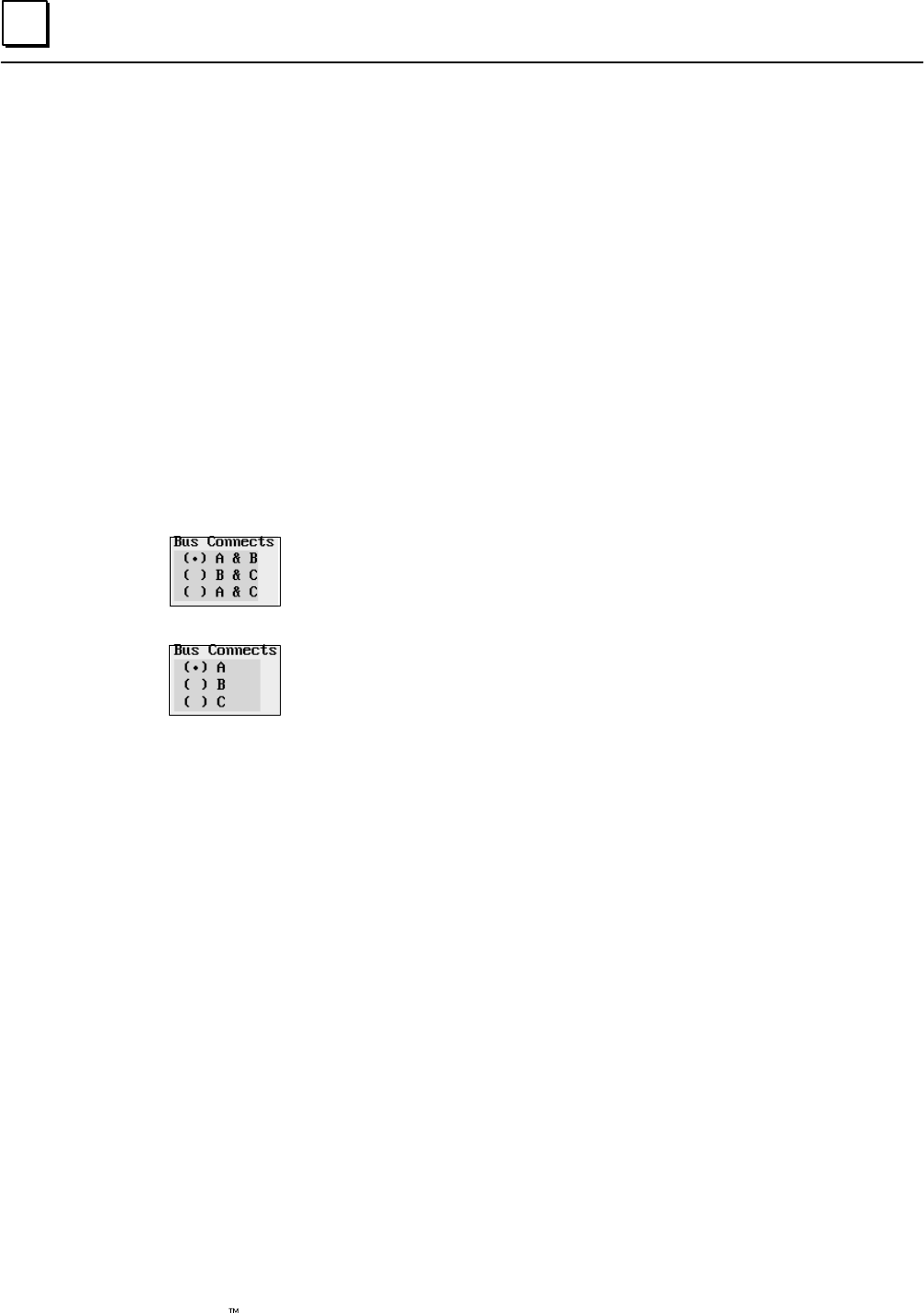
6
6-32 Genius Modular Redundancy Flexible Triple Modular Redundant (TMR) System
User’s Manual – March 1995 GFK-0787B
Default State: Choose a default state: OFF (0), ON (1), or hold last state.
For a triplex group, this state will be provided to the application program
if communications from all three blocks in the group are lost (if Voting
Adaptation is 3–2–1–0). Alternatively, if Voting Adaptation is set to
3–2–0, this state is provided to the application program if
communications from two blocks in the group are lost.
For a duplex group, this state will be provided to the application program
if communications from both blocks in the group are lost.
For a simplex group, this state will be provided to the application program
if communications from the single block are lost.
Hot Standby: Select whether unused circuits to be used as outputs will
operate in Hot Standby mode (see chapter 3 for a description of Hot
Standby operation).
Bus Connects: a triplex group connects to all three busses, so no entry is
needed for Bus Connects. For a duplex or simplex group, specify the bus
connections as explained below.
For a duplex group, configure the two busses the group is connected to: A
(from the PLC using serial bus address 31) and B (from the PLC using
serial bus address 30), or B and C (the PLC using serial bus address 29)
or A and C.
For a simplex group, configure the bus the group is connected to: A (from
the PLC using serial bus address 31), B (from the PLC using serial bus
address 30), or C (from the PLC using serial bus address 29).
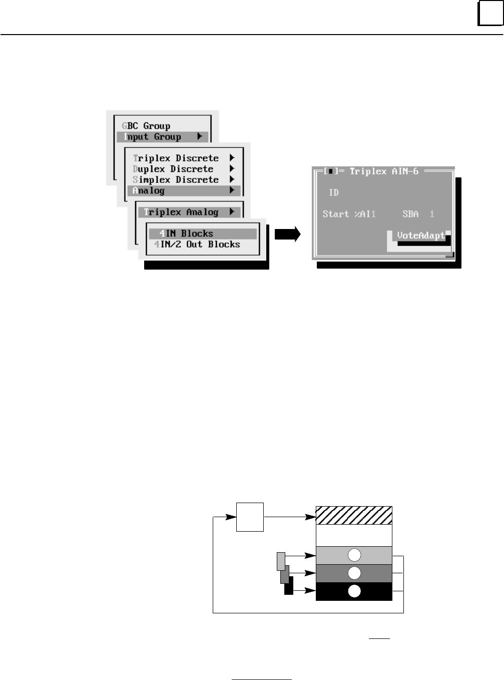
6
6-33GFK-0787B Chapter 6 Configuration
Analog I/O Group Configuration
Select Analog to configure any analog group. Select a triplex, duplex, or simplex analog
input group, then select the block type (6 inputs or 4 inputs/2 outputs). For example:
Note: A “simplex” input group has just one I/O block, installed on one bus, but
configured as a GMR block. It is not the same a “non-voted” block. To configure a GMR
group with just one analog block, select Simplex Analog from the menu of analog group
types as described above.
Enter a name or a description of up to 12 characters, such as
“in group 6”. This entry is for your information only. It is not used by
the GMR software.
The voted analog references start at %AI0001. The size of the voted
analog input area is determined by the number of voted analog inputs
including spares. Within this area, enter the starting %AI Input Table
reference for the block. This will be the %AI address of the voted input
data. The actual %AI references used for the “raw” input data from the
block (shown as A inputs, B inputs, C inputs in the diagram below) are
configured using the Logicmaster 90 software. The GMR configuration
software will provide a printout of the addressing required for
Logicmaster 90. The allowable reference range is 1 to 1024.
Voted Inputs
non-voted
Inputs
Input
Voting
Logic
A inputs A
B
C
B inputs
C inputs
%AI0001
Duplicate addresses are not allowed within a GBC group. You will not
be permitted to continue until you have entered a unique address.
Enter a serial bus address from 0 to 28. Duplicate bus addresses are also
not permitted within a GBC group. However, each block in the group uses
the same serial bus address on its respective bus.
ID
Start %AI
SBA
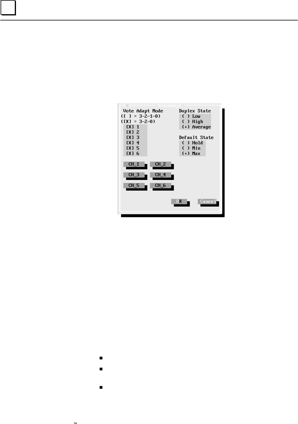
6
6-34 Genius Modular Redundancy Flexible Triple Modular Redundant (TMR) System
User’s Manual – March 1995 GFK-0787B
Specify how each circuit in a triplex or duplex group should utilize vote
adaptation For a simplex group, this option does not apply.
If a failure (discrepancy fault, or Genius fault) occurs, the GMR software
rejects the faulty data. Depending on the configuration entered here,
input voting may go from three inputs to two inputs to one input, or
from three inputs to two inputs to the configured default value.
For a 4 input/2 output block group, the window shows only four inputs.
Vote Adapt Mode:
For a Triplex group, if voting should go from three inputs to two to one,
select 3–2–1–0. If voting should go from three inputs to two to the
default value, select 3–2–0.
For a duplex group, if voting should go from two inputs to one, select 3– 2– 1– 0.
If voting should go from two inputs to the default value, select 3– 2– 0.
Duplex State:
For a triplex group, the Duplex State determines the vote type when there
are two analog inputs present. It may be configured as the higher actual
input value, the lower value, or an average of the two. For more
information, see page 4-13.
For a duplex group, the voted input data can be:
an average of the two channels that are present.
mid-value selection based upon the two input channels that are present,
with the third (unused) channel assigned to its configured low value.
mid-value selection based upon the two input channels that are present,
with the third channel assigned to its configured high value.
For a simplex group, this information is not used.
Vote
Adaptation
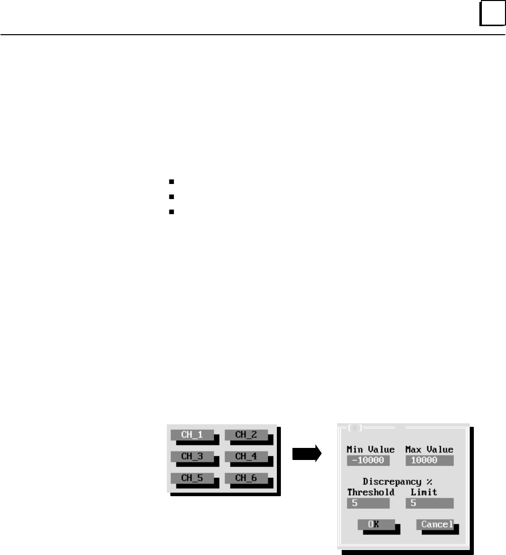
6
6-35GFK-0787B Chapter 6 Configuration
Default State:
For a triplex group, if all three blocks in the group are lost or if only two
blocks are lost and Voting Adaptation is selected as 3–2–0, the GMR
system software will use a selected minimum or maximum value (see
below) in voting, or hold the last value updated.
For a duplex group, select what should happen if both inputs for a
channel are lost or if one block is lost and Voting Adaptation is selected
as 3–2–0. The input can be:
set to its configured maximum value.
set to its configured minimum value.
Hold its last value.
For a simplex group, select which of the above should be done if the input
data for the channel is lost.
Maximum, Minimum: The maximum and minimum values (shown in
the next illustration) entered for an input represent the block’s
configured engineering units. The maximum and minimum values are
used in two ways. First, either the specified maximum or minimum
value can be used as the Default State if actual input data for that
channel is not available. Second, the maximum and minimum values
entered here represent the full-scale deflection for the input. They are
used by the software to monitor the point for limit discrepancy. This is
explained in more detail on the next page.
Enter a maximum and minimum value for each GMR analog input
channel by first selecting the channel (using the mouse or Tab and
Return keys).
The range for either maximum or minimum is –32767 to +32767.
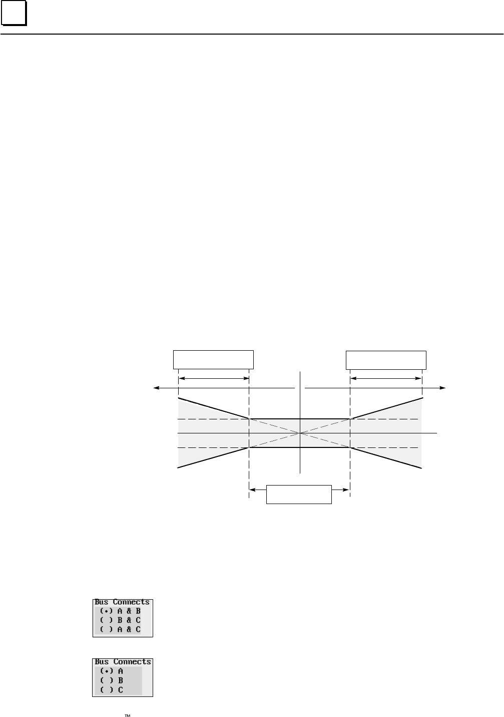
6
6-36 Genius Modular Redundancy Flexible Triple Modular Redundant (TMR) System
User’s Manual – March 1995 GFK-0787B
Threshold Discrepancy: Specify by what percent an individual input
for the channel may deviate from the voted input value. During
operation, if any of the corresponding physical inputs deviates from the
voted input value by more than this amount (in either direction), it will
generate a fault that must be cleared by the application program.
For example, if the physical inputs for a channel were 91, 100, and 111
degrees, the voted input value would be 100 degrees. If the Discrepancy
Threshold for the channel had been configured as 10%, the input
reporting 111 degrees would be outside the acceptable range.
Limit Discrepancy: Similarly, specify by what percent an individual input
for the channel may deviate from the full scale deflection of the channel
(represented by the entries maximum and minimum value). During
operation, if any of the corresponding physical inputs deviates by more
than this amount (in either direction) from the voted input value, it will
generate a fault that must be cleared by the application program.
For example, if the physical inputs for a channel were 9, 10, and 15, and
the full scale deflection were configured at 200, with a limit discrepancy
of 10%, the voted input would be 10 and all three inputs would be
within the discrepancy limit (of 20), and no fault would be reported.
Analog Discrepancy Thresholds and Limits
%AI
Voted
Input
Limit Discrepancy
% of FSD
PositiveNegative
Threshold Discrepancy
% of Reading
Threshold Discrepancy
% of Reading Discrepancy
Value
NOTE: Both a Threshold Discrepancy and a Limit Discrepancy must
exist for a input channel before an Analog Input Discrepancy is logged
in the fault table.
Bus Connects: a triplex group connects to all three busses, so no entry is
needed for Bus Connects. For a duplex or simplex group, specify the bus
connections as explained below.
For a duplex group, configure the two busses the group is connected to: A
(from the PLC using serial bus address 31) and B (from the PLC using
serial bus address 30), or B and C (the PLC using serial bus address 29)
or A and C.
For a simplex group, configure the bus the group is connected to: A (from
the PLC using serial bus address 31), B (from the PLC using serial bus
address 30), or C (from the PLC using serial bus address 29).
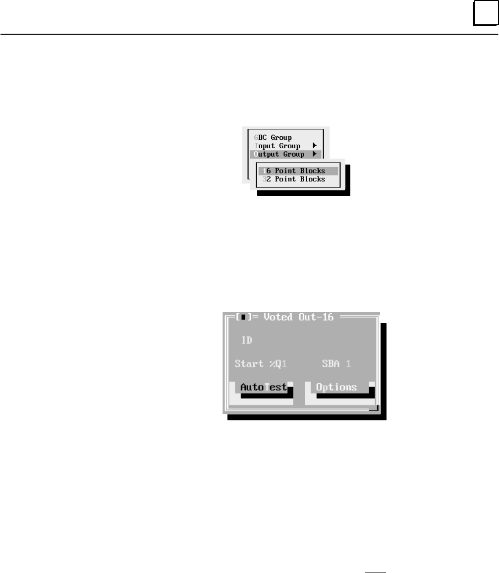
6
6-37GFK-0787B Chapter 6 Configuration
Configuring the Output Subsystem for a Bus Controller Group
Next, configure the output subsystem for that bus controller group.
Select Output Group from the menu.
Repeat the following procedure for each group in the output subsystem:
Note: It is possible for a bus to include output blocks that are not part of the GMR system. Do
not include non–GMR blocks in the GMR configuration. Non-GMR blocks are included in the
Logicmaster configuration and in the Genius block configuration, however.
Select either 16-circuit Blocks or 32-Circuit Blocks from the menu. An additional
configuration screen appears to configure the GMR features for that group.
On this screen, use the tab key to move from item to item.
Enter a name or a description of up to 12 characters, such as
“out group 1”.
Enter the starting %Q Input Table reference for the group (all blocks in
the group will have the same Output Table reference addresses). The
allowable reference ranges are:
0001 to 0080 (788 CPU)
0001 to 2048 (789 CPU)
Duplicate addresses are not allowed within a GBC group. You will not
be permitted to continue until you have entered a unique address.
Enter a serial bus address (also referred to as the “device number”) from 0 to
28. Each block the group uses same serial bus address on its respective bus. The
exception to this is the 4th block (“block D”) in the output group, which will
have its SBA identified in the “Options” window.
Highlight this item then press the space bar key to display a screen for
setting up Output Autotest for the output circuits. Follow the
instructions on the next page to complete the entries on that screen.
ID
Start %Q
SBA
Auto Test
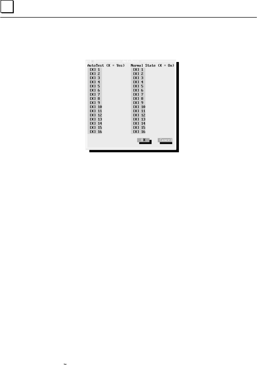
6
6-38 Genius Modular Redundancy Flexible Triple Modular Redundant (TMR) System
User’s Manual – March 1995 GFK-0787B
Autotest: By default, each circuit is set up for autotesting, as shown by
the X next to the circuit number. To turn off autotesting for any circuit,
select that circuit (click on the circuit or select it using the cursor keys).
Press the space bar key to remove (or replace) the X.
Note: It is possible for an
output block to include
circuits that are not part
of the GMR system, and
which are not to be
autotested. Be sure to turn
autotest off for any unused
and non-GMR circuits.
Normal State: By default, each circuit is set up to have On as its Normal
(non-alarm) State for purposes of autotesting. The selection is shown by
the X next to the circuit number. If the autotest alarm state of any circuit
should be Off, select that circuit (click on the circuit or select it using the
cursor keys). Press the space bar key to remove (or replace) the X.
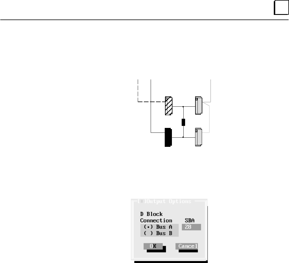
6
6-39GFK-0787B Chapter 6 Configuration
Finally, for each 4-block group, specify the bus and location (serial bus
address) of the fourth block (the “D” block) in the group. While the A, B,
and C blocks are installed on busses A, B, and C, respectively, the D
block must be installed on either bus A or bus B (as in the illustration
shown below).
Load
Source
Blocks
Sink
Blocks
Bus A Bus B
Bus C
AB
CD
While busses A, B, and C can use the same serial bus address on their
respective busses, block D, which is on the same bus as either block A or
block B, must have a different serial bus (because each device on a
Genius bus must have a unique serial bus address).
Options
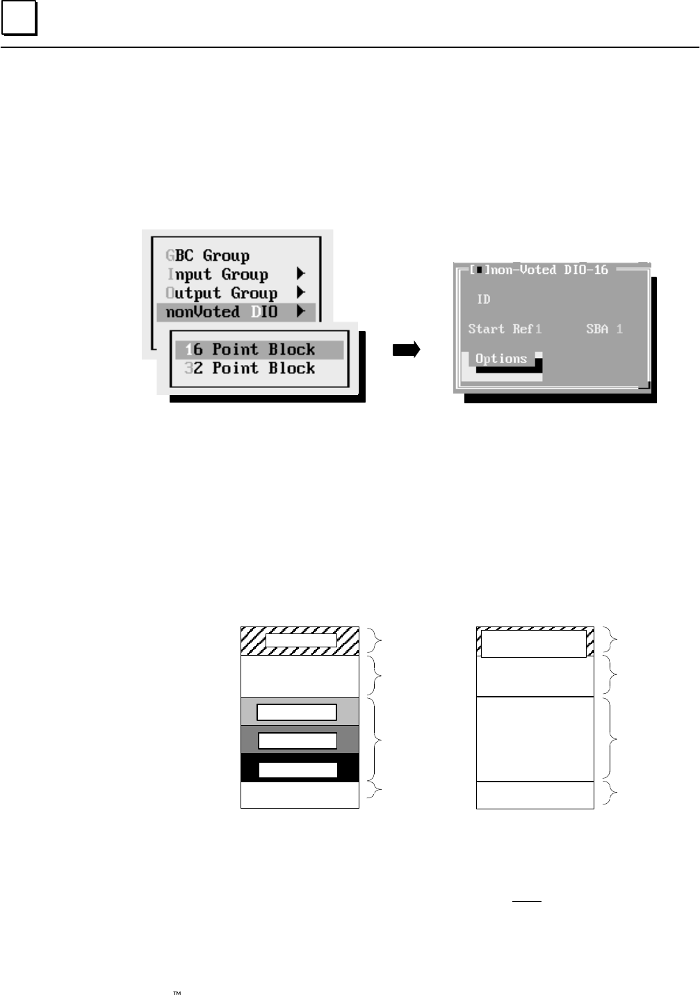
6
6-40 Genius Modular Redundancy Flexible Triple Modular Redundant (TMR) System
User’s Manual – March 1995 GFK-0787B
Configuring the Non-Voted Discrete I/O for a Bus Controller Group
If the bus controller group includes any non-voted discrete I/O, select nonVoted D I/O.
(Inputs and outputs may be mixed on a block.) Non-voted I/O are inputs and outputs
on individual blocks (blocks that are not part of an input or output group) that are
present on the GMR busses.
A sub-menu appears where you specify whether the blocks in that particular group are
16-point or 32-point blocks. For example:
Press Return to configure the block. The configuration screen shown at the right appears.
Enter a name or a description of up to 12 characters, such as
“nonvoted 1”. This entry is for your information only. It is not used by
the GMR software.
Enter the starting I/O Table reference for the block. This is the %I and %Q
addresses used for the block’s I/O data.
Voted I/O data and non-voted I/O data use different areas of the I/O
tables. This is shown below, and explained in more detail on page 7-5.
(Discrete I/O tables are shown; the analog I/O tables are similar).
Discrete Input Table
Voted Inputs
Available for
non-voted Inputs
Bus A inputs
Bus B inputs
Bus C inputs
Reserved inputs
Discrete Output Table
Logical Redundant
Outputs
Available for
non-voted Outputs
Physical Redundant
Outputs
Reserved memory
%I0001
%I1024 or %I12288 %Q1024 or
%Q12288
%Q0001
non-voted
I/O
Inputs to
PLC
Bus A, B, C
Inputs
Reserved
non-voted
I/O
Outputs
from PLC
Reserved
Output
Memory
Reserved,
Outputs
to Blocks
The starting address for non-voted data depends on the amount of
redundant data, as explained in chapter 7.
Duplicate addresses are not allowed within a GBC group. You will not
be permitted to continue until you have entered a unique address.
Enter a serial bus address (also referred to as the “device number”) from
0 to 28.
ID
Start Ref
SBA
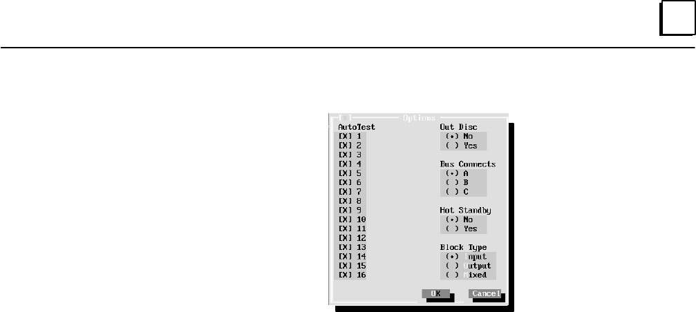
6
6-41GFK-0787B Chapter 6 Configuration
Select this item to display additional configuration choices.
Input Autotest: This feature applies to 16- and 32-circuit DC Sink/Source
I/O Blocks IC660BBD020, 021, 024, and 025 only. The block can be either
in GMR mode or not in GMR mode.
If any input circuits on the blocks in the group should be autotested, select
them here. Circuit 16 must have autotest enabled. If no circuits are to be
autotested, circuit 16 can have autotest disabled and input devices can be
wired directly to the power source instead of being wired to circuit 16.
By default, each circuit is set up for autotesting, as shown by the X next
to the circuit number. To turn off autotesting for any circuit, select that
circuit (click on the circuit or select it using the cursor keys). Press the
space bar key to remove the X. Note: For all unused circuits on the
block, autotest should be set to off. Also, it is possible for an input block
to include I/O circuits that are not part of the GMR system, and which
are not to be autotested. Be sure to turn autotest off for non-GMR circuits.
Output Discrepancy: Specify whether the block should report output
discrepancies. This applies to 16- and 32-circuit DC Sink/Source I/O Blocks
IC660BBD020, 021, 024, and 025 only. The block must be in GMR mode.
Bus Connect: Select the bus to which the block is connected.
Hot Standby: Specify whether the block should use Hot Standby output
redundancy. This feature applies to 16- and 32-circuit DC Sink/Source I/O
Blocks IC660BBD020, 021, 024, and 025 only. Operation of Hot Standby mode
is described in chapter 3. If the block is not in GMR mode, selecting Hot
Standby here tells the system to configure the block to send fault reports to
three PLCs.
Block Type: Specify input, output, or mixed I/O. If the block will use the
Input Autotest feature, it must be set up as a mixed I/O block.
Options
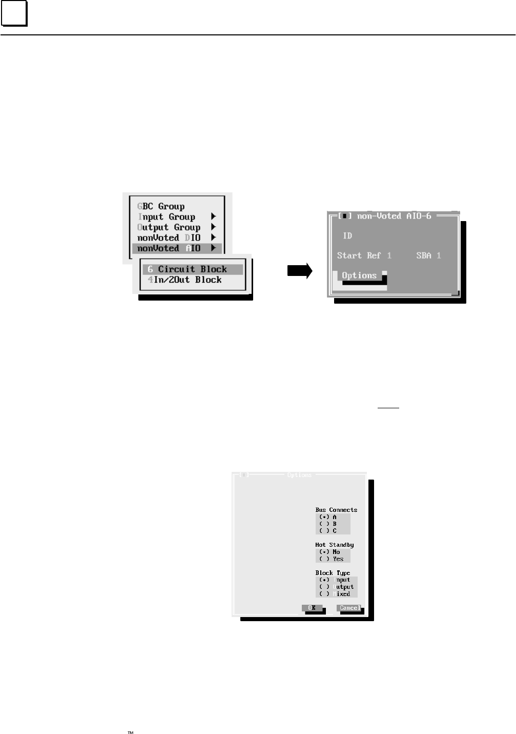
6
6-42 Genius Modular Redundancy Flexible Triple Modular Redundant (TMR) System
User’s Manual – March 1995 GFK-0787B
Configuring the Non-Voted Analog I/O for a Bus Controller Group
If the bus controller group includes any non-voted analog I/O, select nonVoted A I/O.
Note: Non-voted analog I/O blocks that are configured here are considered part of the
GMR system. It is possible for a bus to include I/O blocks that are not part of the GMR
system. Do not include non–GMR blocks in the GMR configuration. Non-GMR blocks are
included in the Logicmaster configuration and in the Genius block configuration, however.
A sub-menu appears where you specify whether the blocks in that particular group are
6-input or 4 input/2 output blocks. For example:
Enter a name or a description of up to 12 characters, such as
“nonvoted 2”. This entry is for your information only. It is not used by
the GMR software.
Enter the starting Analog I/O Table reference for the block. This is the %AI
and/or %AQ addresses used for the block’s I/O data. The allowable
references are: 0001 to 8192
Duplicate addresses are not allowed within a GBC group. You will not
be permitted to continue until you have entered a unique address.
Enter a serial bus address from 0 to 28.
Select this item to display additional configuration choices.
Hot Standby: Hot standby mode is supported for analog blocks. This mode
allows analog outputs to respond to CPU A or B. Selecting Hot Standby here
tells the system to configure the block to send fault reports to three PLCs.
Bus Connect: Select the bus to which the block is connected.
Block Type: Specify input, output, or mixed I/O.
ID
Start Ref
SBA
Options
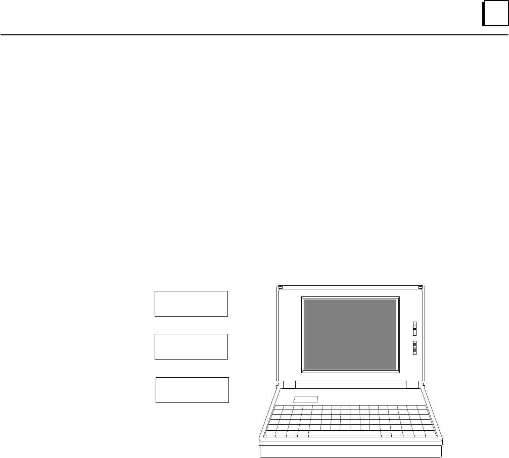
6
6-43GFK-0787B Chapter 6 Configuration
Creating the G_M_R10 Output File
The output of the GMR configuration process is a program block named G_M_R10,
which can be imported to the application program folder in Logicmaster 90.
The Write Output function of the GMR configuration software automatically creates a
file named G_M_R10.EXE. This is the file required by Logicmaster 90.
If the configuration you want to use is not the one currently displayed, first use the file
utilities of the GMR configuration software to load it into RAM memory.
Example:
Previously, you created and saved three different configuration files, named CONFIG1,
CONFIG2, and CONFIG3, as represented below. All three files are currently stored on
your hard disk. A different configuration, CONFIG4, is currently in RAM memory.
Saved
Configuration
Files
CONFIG1.SAV
CONFIG2.SAV
CONFIG3.SAV
CONFIG4
Configuration
in RAM
At this point, you decide you want to use CONFIG3 as the GMR configuration for the
application. First, you need to load CONFIG3 into RAM memory. If you wanted to keep
the file already in RAM memory, CONFIG4, you would need to use the file functions of
the GMR software to save it.
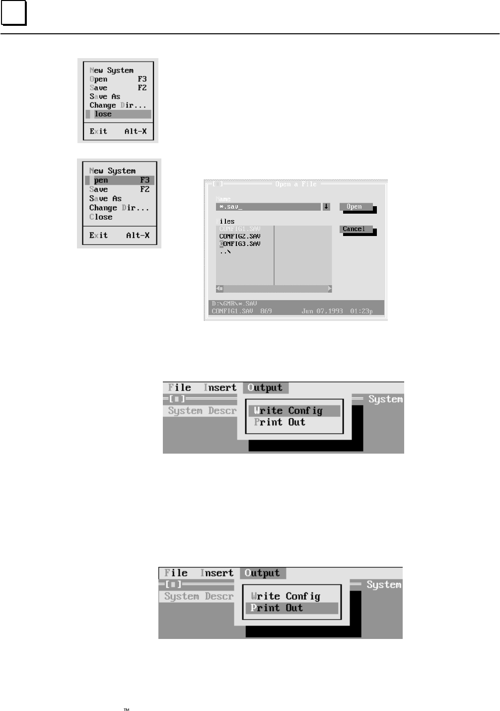
6
6-44 Genius Modular Redundancy Flexible Triple Modular Redundant (TMR) System
User’s Manual – March 1995 GFK-0787B
In this example, you decide that you don’t want to keep CONFIG4, so
you go to the file functions and select Close. That ends the configuration
session without creating a .SAV file.
Next, you select Open a Configuration File. A list of files appears:
Click on the name of the .SAV file you want, or type in its filename. When the filename
appears in the name box, click on Open. The configuration file is loaded into RAM. With
the correct configuration file displayed, select Output: Write Config to create a
G_M_R10 output file.
After creating the file, you can add it to the application program as instructed on page
7-29.
Printing the GMR Configuration
When the GMR configuration is finished, select Output to print it out. The GMR
software establishes many parameters of the system configuration that you will need to
be familiar with during Logicmaster configuration and Genius block configuration.
Printing defaults to the parallel port of the computer running the GMR Configuration
Software. If you want to redirect printing to a serial port, exit to DOS and use the DOS
“mode” command, as instructed in your DOS manual.
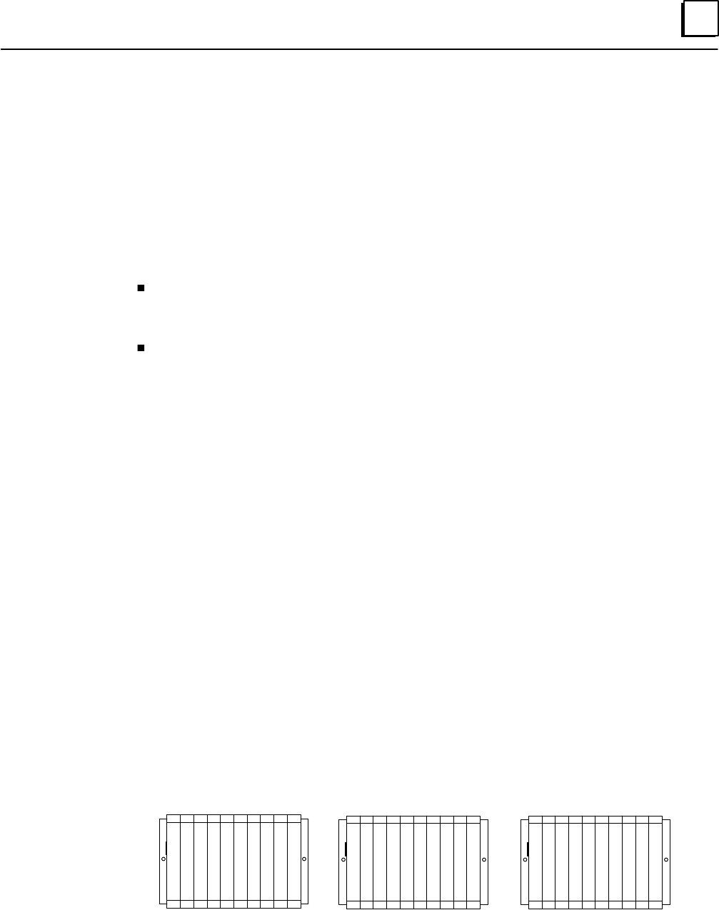
6
6-45GFK-0787B Chapter 6 Configuration
Completing the Logicmaster 90 Configuration
Logicmaster 90 configuration steps for a PLC In a GMR system are the same as for a
non-GMR system. A typical configuration is summarized on the following pages. You
should refer to the Logicmaster 90 Software User’s Manual for detailed configuration
instructions.
Since the configuration and program for the redundant PLCs in a GMR system are
nearly identical, it is easiest to complete the configuration (and program) for one PLC,
then copy and edit them for the other PLCs.
One necessary change in the configuration is to edit the serial bus addresses (also
referred to in other Genius documentation as “device numbers” of the Bus
Controllers). See below.
Genius I/O blocks use the same reference addresses in each of the redundant PLCs,
so reference addresses are not changed from PLC to PLC.
It is very important to be sure that entries made during Logicmaster configuration match
similar entries made during GMR configuration. Complete the GMR configuration first,
print it out, and use the printout for reference during the Logicmaster configuration.
Configuring Bus Controllers
A Series 90-70 PLC can have up to 31 Genius bus controllers. In a GMR system, bus
controllers perform the dual function of supporting Genius I/O and providing inter-PLC
communications. The number of bus controllers supporting GMR functions in a GMR
system must be the same in each PLC. Other, non-GMR, bus controllers can be added to
an individual PLC configuration.
All Genius bus controllers that are included in the GMR system must be assigned serial bus
addresses (device numbers) as follows:
PLC A bus address 31
PLC B bus address 30
PLC C bus address 29
For example, if the system consists of three PLCs with two triple-bus GMR I/O
subsystems, each PLC would require six bus controllers. All six in PLC A would have to
be configured at bus address 31, all six in PLC B at bus address 30, and all six in PLC C at
bus address 29.
29
29
29
29
29
29
30
30
30
30
30
30
31
31
31
31
31
31
PLC A PLC B PLC C
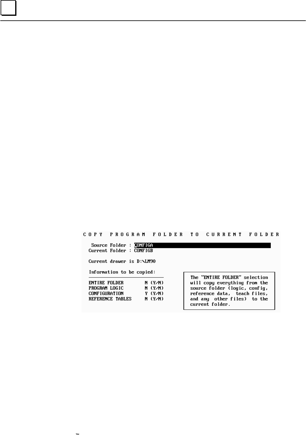
6
6-46 Genius Modular Redundancy Flexible Triple Modular Redundant (TMR) System
User’s Manual – March 1995 GFK-0787B
Creating and Copying the PLC Configuration
The recommended method of completing the PLC configuration is described below.
A. Create a Folder for PLC A, PLC B, and PLC C. In this discussion, PLC A is
considered to be the PLC using serial bus address 31, PLC B is the one that uses
serial bus address 30, and PLC C is the one that uses 29.
B. Select the folder for PLC A. With the GMR configuration printout as a reference,
complete its Logicmaster configuration. Summary steps are described on the
following pages.
C. Use the Copy Folder feature of the Logicmaster 90 programming software to
copy the configuration of PLC A to the folders for PLC B and PLC C.
(1) From the Logicmaster configuration software, return to the Logicmaster
programming software. Select the Program Folder functions.
(2) In the Program Folder functions menu, select F1 ... Select/Create a Program
Folder. On the Select/Create screen, select the folder for the second PLC (for
example CONFIGB) as the current folder.
(3) In the Program Folder functions menu, select F10, Copy Contents of Prog
ram Folder to Current Program Folder. On the Copy Folder screen:
(a) For Source Folder, enter the name of the folder containing the
configuration of PLC A (for example, CONFIGA).
(b) For Information to be copied: set only Configuration to yes.
D. If there are three PLCs, repeat this for the other PLC.
E. Edit the configurations for PLC B and PLC C as necessary.
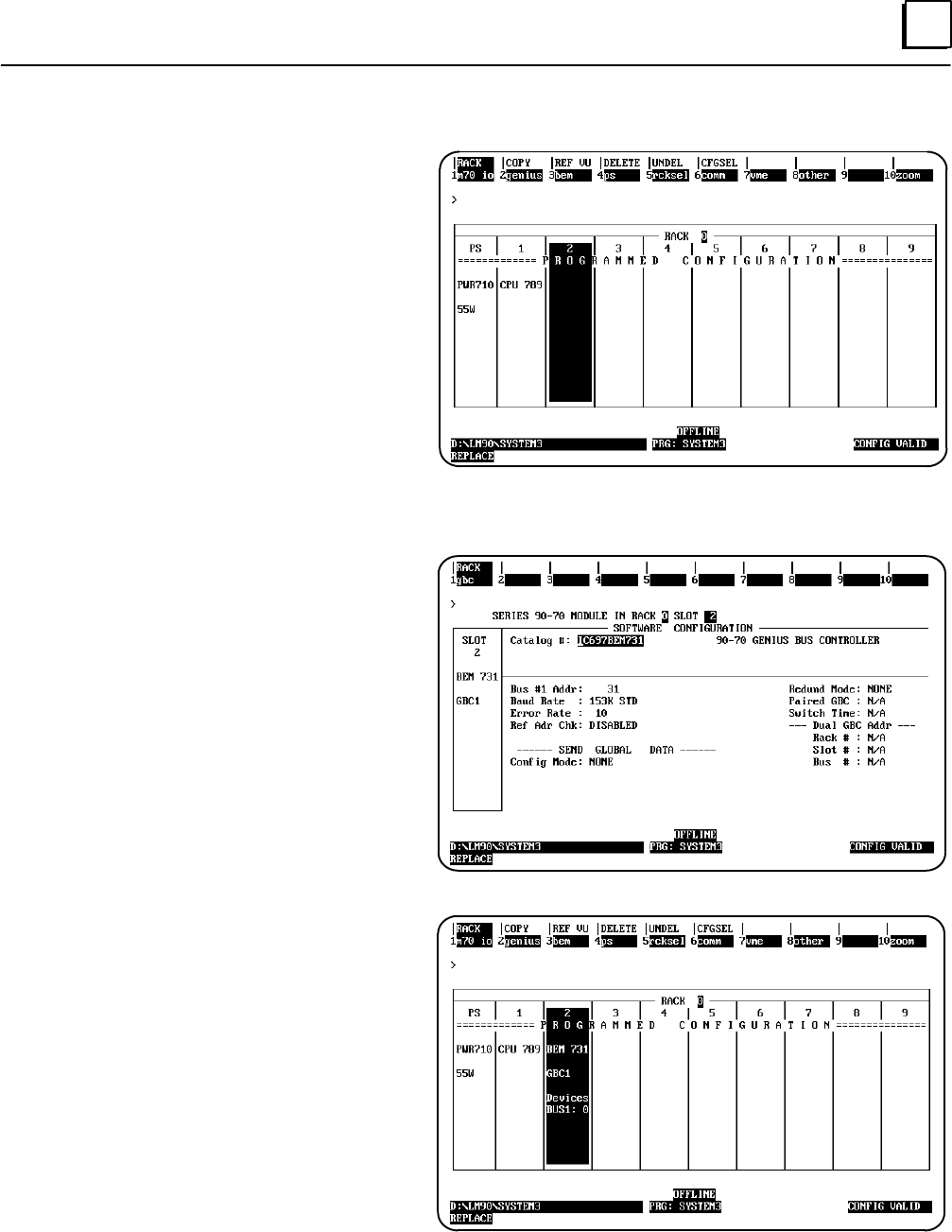
6
6-47GFK-0787B Chapter 6 Configuration
Logicmaster Configuration Summary
1. Change the CPU to the correct type (in
this example, it is a CPU 789) and add
appropriate memory.
2. Move the cursor to the rack and slot
location for the first Bus Controller.
Be sure the location matches the entry
made with the GMR Configuration
Software.
3. Press F2 (genius).
4. From the Catalog # screen, press F1
(gbc).
5. From the Description screen, press Enter.
6. Complete the entries on the left side
of the screen. Remember that all of
the bus controllers in the PLC must
have the same serial bus address (31
in the illustration at right). Leave the
Ref Adr Chk selection disabled (the
default).
7. On the right side of the screen, leave
Redund mode set to NONE. The
entries below it cannot then be
edited.
8. If this Bus Controller was configured in
the INIT DATA window of the
Configuration utility, for Global Data,
set the field for Config Mode to
MANUAL. Enter a beginning %R
reference and length (64) for global
data. See the Programming chapter
of this book for more information
about Global Data addressing.
9. Press the ESC key to return to the
rack configuration screen.
10. The rack configuration screen now
includes the Bus Controller.
11. Press F10 (zoom) to go to the bus
configuration screen.
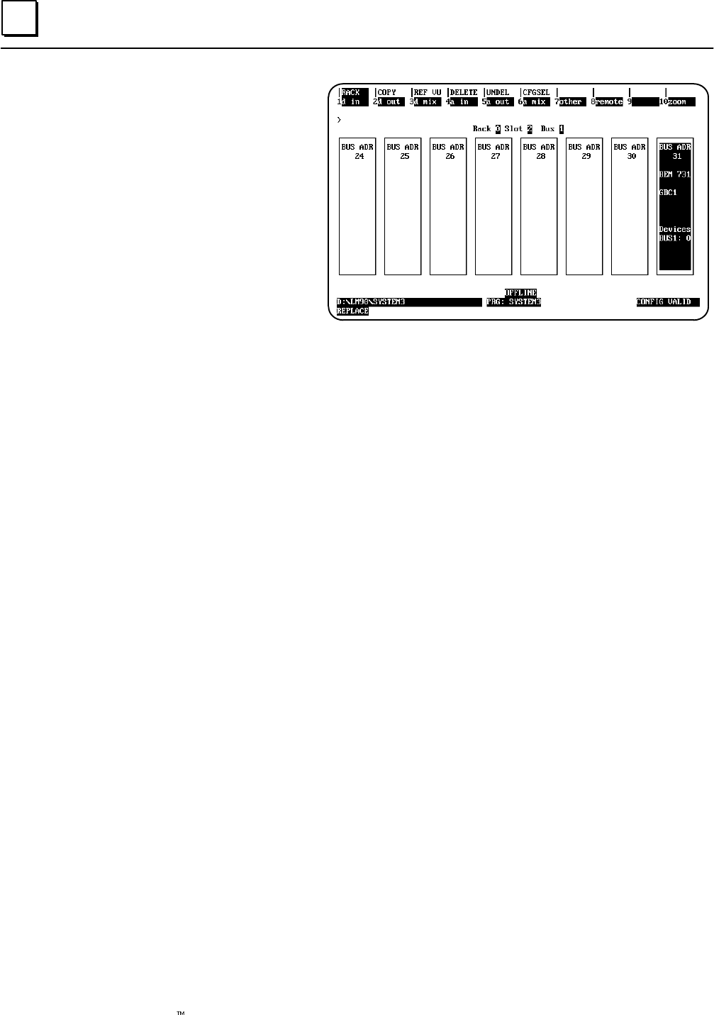
6
6-48 Genius Modular Redundancy Flexible Triple Modular Redundant (TMR) System
User’s Manual – March 1995 GFK-0787B
12. On the bus configuration screen, the Bus
Controller appears at its configured Bus
Address, 31 in this example.
13. From here, you can configure the devices
on the bus, including the other bus
controllers in the group. Each bus controller
must be configured both individually and as a
device on the bus of the other bus controller(s)
on the same bus. In addition, the bus
controllers on a Global Data bus must be
configured with an appropriate Global Data
address and length.
When configuring I/O blocks, be sure to
match I/O address assignments and serial
bus addresses of GMR blocks to those
made using the GMR Configuration
Software.
Note: For input blocks in GMR groups, the I/O addresses configured on these screens are for the “raw”
input data received directly from the blocks (for the A, B, and C areas of the Table, as described in the
Programming chapter. For output blocks in GMR groups, the output addresses configured on these
screens are for the physical redundant output data (not the logical addresses used in the application
program). These addresses are produced by the GMR Configuration Software, and are listed in the
configuration printout.
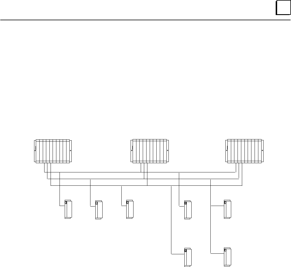
6
6-49GFK-0787B Chapter 6 Configuration
Configuring GMR Bus Controllers and I/O Blocks
Each bus controller that serves the same input and/or output groups is configured similarly;
so it is usually easiest to copy the first completed bus/bus controller in a group to configure
the other bus controller(s) in the same group. Any additional changes can be made to the
individual bus controller/bus configurations as needed (for example, to accommodate
non-voted I/O on a bus, or the “D” block of a 4-block output group.
GMR redundant input blocks in a group each have a unique “raw” data address on each bus
in the same PLC. However, the blocks have the same reference addresses in another GMR
PLC.
GMR redundant outputs in a group have the same reference addresses on each bus in the
group.
%I11265
31
31
31
31
31
31
%I11521 %I11777
Bus C
Bus A
30
30
30
30
30
30
Bus B
PLC A PLC B
29
29
29
29
29
29
PLC B
%Q12033 %Q12033
%Q12033 %Q12033
AB C A B
CD
Input blocks in a group are at
different “raw” data addresses Output blocks in a group are
at the same physical address

6
6-50 Genius Modular Redundancy Flexible Triple Modular Redundant (TMR) System
User’s Manual – March 1995 GFK-0787B
Configuring Genius I/O Blocks
Genius I/O block configuration for a GMR system is similar to configuration for a
non-GMR system. You should refer to the Genius Discrete and Analog Blocks User’s Manual
for specific configuration instructions.
A copy of the configuration prepared with the GMR Configuration Software should be
used for reference during block configuration, to assure consistency.
Editing the Reference Addresses
For Genius blocks in a GMR system, blocks within a group use the same reference
addresses in each of the redundant PLCs, so these are not changed.
Editing the Block I/O Type
Any discrete block that is part of a redundant input group (triplex, duplex, or simplex)
must be configured as a “combination” I/O block.
Copying Configurations
Because the blocks in a redundant input or output group usually have the same
configuration, it would be most convenient to copy configuration from one block to
another. However, the Copy Configuration feature of the Genius Hand-held Monitor
only works when blocks are online on the same bus (and GMR blocks in a group are on
separate busses). Of course, it is possible to use the Copy Configuration feature between
similar blocks on a bus that are not in the same group.
Setting Up Blocks for Fault Reporting
Configuring a block for CPU Redundancy = GMR automatically sets up the block to
send three fault reports when a fault occurs; one fault report each to serial bus addresses
29, 30, and 31. The blocks require no further setup to send multiple fault reports.
Setting Up Non-GMR Blocks to Send Multiple Fault Reports
Inputs-only blocks automatically send up to two Fault Reports to serial busses 30 and 31.
However, non-GMR output and mixed I/O blocks must be configured for Hot Standby
redundancy to send two Fault Reports to serial bus addresses 30 and 31.
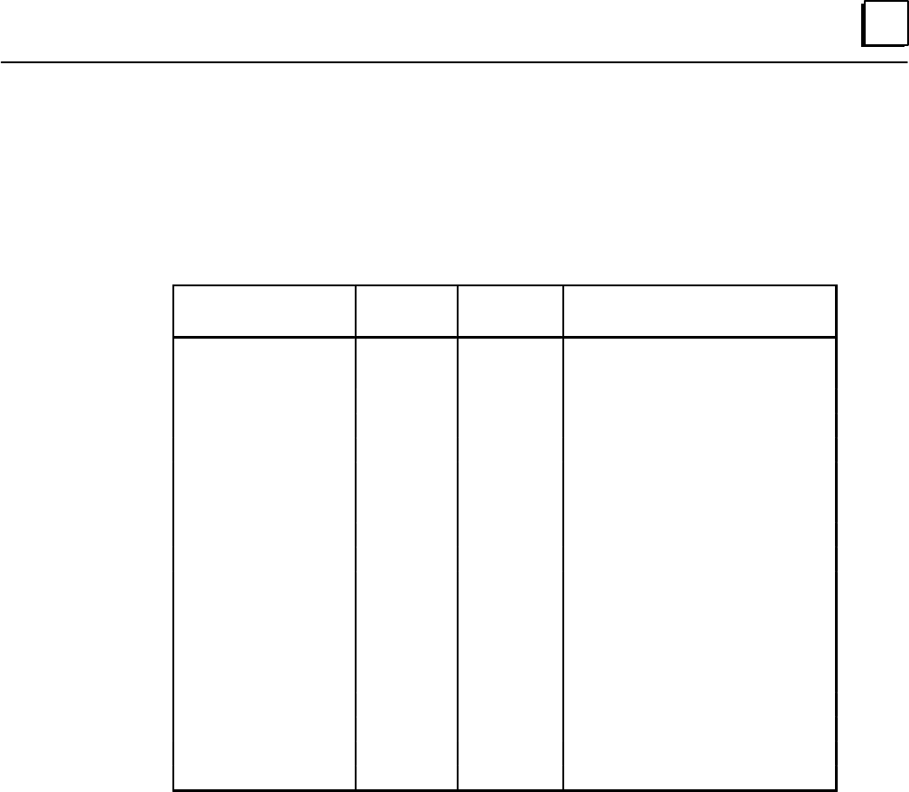
6
6-51GFK-0787B Chapter 6 Configuration
Configuring 16-Circuit and 32-Circuit Discrete DC Blocks
The table below lists configuration parameters for 16-circuit and 32-circuit discrete
blocks. Configuration options with special requirements in GMR systems are described
after the table. Configuration options that are not changed for GMR systems are not
described here. Note that blocks do not prevent selecting incorrect parameters for a
GMR system. It is important to configure blocks appropriately for GMR use.
Feature Circuit or
Block Factory
Setting Selections
Device Number Block null 0 to 31 (a number must be selected)
Reference Address Block none Depends on host CPU type
Block I/O Type Block input input, output, combination
Baud Rate Block 153.6 std 153.6 std, 153.6 ext, 76.8, 38.4 Kbd
Pulse Test for Outputs Block enabled enabled, disabled
Input Filter Time
(16–ckt)
(32 ckt)
Block 20mSec 5–100mSec
1–100mSec
Circuit I/O Type Circuit input input, output, tristate input*
Report Faults Circuit yes yes, no
Hold Last State Circuit no yes, no
Output Default State Circuit off on, off
Detect No Load* Circuit yes yes, no
Overload Shutdown* Circuit yes yes, no
BSM Present Block no yes, no
BSM Controller Block no yes, no
Output Default Time Block 3 bus scans (for bus redundancy) 2.5 or 10 sec
Redundancy Mode Block none none, hot standby, duplex, GMR
Duplex Default Block off on, off
*Available only with 16–circuit blocks.
In a triple-redundancy GMR system, serial bus addresses 29 – 31 are
reserved for the bus controllers. By convention, serial bus address 0 is
often used for the Genius Hand-held Monitor. The serial bus addresses
assigned to the blocks must match those entered using the GMR
Configuration Software. Therefore 1–28 are available for blocks.
All the blocks in an input group must be configured to use the same
serial bus address. In a 4-block output group, three of the blocks (one
each on bus A, B, and C) use the same serial bus address. The fourth
block, which must be located on either bus A or bus B, must be assigned
a different serial bus address.
All blocks in the same output group must use the same reference
address. However, blocks in an input group each have a unique address,
as explained on page 6-37. Refer to the reference address assignments
made using the GMR Configuration Software when assigning addresses
to blocks. Reference addresses must be assigned on 8-bit boundaries.
The system may include individual blocks that are not set up for
redundancy.
Device
Number
(serial bus
address)
Reference
Address

6
6-52 Genius Modular Redundancy Flexible Triple Modular Redundant (TMR) System
User’s Manual – March 1995 GFK-0787B
Any discrete block that is part of a redundant input group (triplex,
duplex, or simplex) must be configured as a “combination” (I/O) type
block.
Any block that is part of an output group must be set up as an
outputs-only block.
Baud rate should be selected on the basis of the calculations in the
Genius I/O System and Communications User’s Manual (GFK-90486). Note
that for correct autotesting in a GMR system, the Genius bus scan time
should not be be more than 60mS.
Pulse-testing should be enabled for all GMR output blocks. It should be
disabled for all GMR input blocks, except for GMR input blocks that have
output circuits that you wish to output pulse test.
Input Filter Time should be set up according to the needs of the application.
If an input block will also have outputs and those outputs will be
pulse-tested, the Input Filter Time must be set at a minimum of 20mS. This is
necessary because the power feed output (the output supplying power for
autotesting input circuits) will also be pulse-tested, and could cause false
inputs at filter times under than 20mS. On 16-circuit blocks, any circuits
configured as tristate inputs must have an Input Filter Time of at least 30mS.
On non-voted blocks in the system, circuits can be any mix of inputs and
outputs.
On blocks in output groups, all circuits should be configured as outputs.
GMR output blocks must not be configured as “outputs with feedback”
blocks. GMR fault monitoring provides this feature.
On blocks in input groups:
GMR input circuits on 16-circuit blocks only can be configured as
regular inputs or tristate inputs. They should be configured as
tristate inputs to permit short-circuit detection. In a system with
normally-energized inputs, short circuit represents Fail to Danger
mode.
Short-circuit detection requires the installation of a zener diode in
series with the field switch. See page 2-7 for details.
If the block will be set up for Input Autotest, circuit 16 must be
configured as an output (regardless of whether it is a 16 or 32-circuit
block).
Fault reporting must be enabled on all GMR block circuits. The
16-circuit and 32-circuit DC Genius blocks will automatically send three
copies of all fault reports; one each to the bus controllers at serial bus
addresses 29, 30, and 31.
Block I/O
Type
Baud Rate
Pulse Test
Input Filter
Time
Circuit I/O
Type
Report Faults

6
6-53GFK-0787B Chapter 6 Configuration
If the block will use Input Autotest, circuit 16 must be configured as an
output, as explained above. For circuit 16, Hold Last State must be
configured to NO.
If the block will use Input Autotest, circuit 16 must be configured with
Output Default set to ON.
Portions of the overall system can be configured for no CPU redundancy,
duplex redundancy, hot standby redundancy, or GMR mode. (See page 5-3
for information about how the configured Redundancy Mode affects Fault
Reporting by blocks in the GMR system).
For 16-circuit and 32-circuit DC blocks, select GMR mode for blocks that
will be part of input or output groups as described in this book.
Individual circuits on the blocks can be configured (using the GMR
Configuration Software) to utilize the special GMR features. GMR mode
can be selected even if there is just one block in an input group, and it
should use the extra diagnostics capabilities provided by GMR.
Select no redundancy for non-critical individual blocks that do not
require any type of redundancy.
The duplex CPU redundancy selection is for blocks on a bus with two
PLCs. This is not the same as duplex GMR redundancy. Conventional
duplex CPU redundancy, which is described in the Genius I/O System
User’s Manual does not provide autotesting, or the other special features
of GMR described in this book.
Hot standby CPU redundancy can be selected for blocks in a GMR
system. Instead of voting on CPU output data, blocks that are set up for
hot standby mode give preference to outputs received from bus
controller 31. Should outputs from 31 fail, a block in hot standby mode
starts using outputs received from bus controller 30. Finally, should
outputs from 30 fail, the block will use outputs from bus controller 29.
(Only the specific types of enhanced 16-circuit and 32-circuit DC discrete
blocks listed in this book are capable of receiving outputs from bus
controller 29. Other types of blocks can only receive outputs from bus
controllers 30 and 31.)
Hold Last
State
Output
Default
Redundancy
Mode
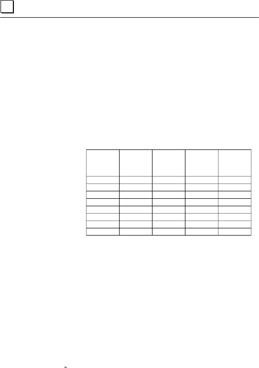
6
6-54 Genius Modular Redundancy Flexible Triple Modular Redundant (TMR) System
User’s Manual – March 1995 GFK-0787B
For output blocks set up for GMR redundancy, the duplex default state
is used when a block determines that only two PLCs are online. The
Duplex Default state of On or Off is used by the 2 out of 3 voting
algorithm in the block, instead of the state that would have been
supplied by the third PLC.
The Duplex Default state determines whether voting will be 1 out of 2
or 2 out of 2 in the On or Off state when only two PLCs are providing
outputs. This is explained below.
The following three tables compare voting results for a block receiving
outputs from all three PLCs with results, and with one of the three
PLCs is offline.
Results of Block Voting with Three PLCs Online
For comparison, this table shows how a block votes on outputs received
from three PLCs. In this case, the block doesn’t use the Duplex Default,
so it is shown as an X (don’t care).
PLC A
Output
State
PLC B
Output
State
PLC C
Output
State
Duplex
Default
Setting in
Block
Output
State
0 0 0 X 0
0 0 1 X 0
0 1 0 X 0
0 1 1 X 1
1 0 0 X 0
1 0 1 X 1
1 1 0 X 1
1 1 1 X 1
Duplex
Default
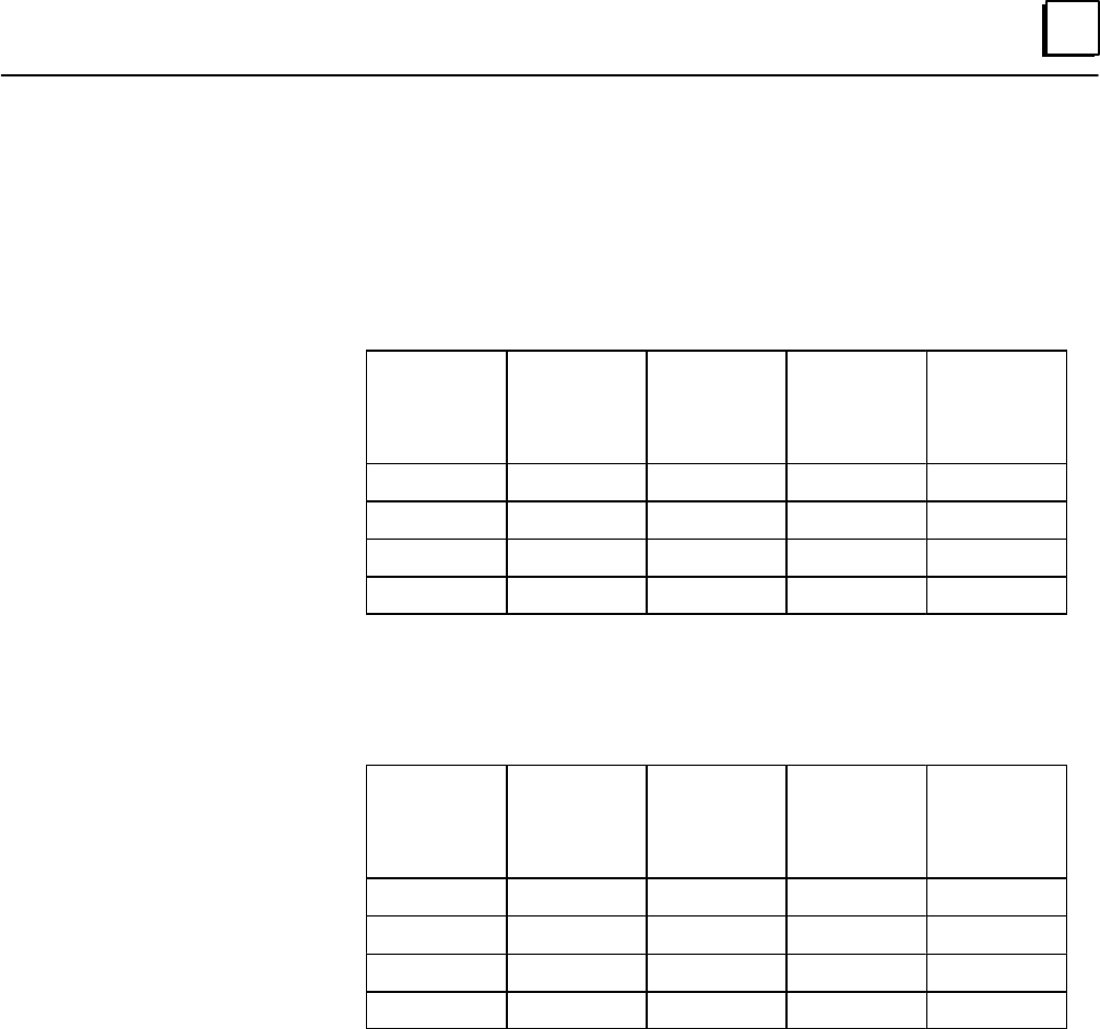
6
6-55GFK-0787B Chapter 6 Configuration
Results of Block Voting with Only Two PLCs Online
In the two tables below, PLC C is shown as offline, but it could be either
of the other two instead.
Using 0 as the Duplex Default state means that when only two PLCs are
online, the voted output state will be 0 if either PLC sets it to 0. It will
not be 1 unless both online PLCs set it to 1.
PLC A
Output
State
PLC B
Output
State
PLC C
Output
State
Duplex
Default
Setting in
Block
Voted
Output
State
0 0 – 0 0
0 1 – 0 0
1 0 – 0 0
1 1 – 0 1
Similarly, using 1 as the Duplex Default state means that when only two
PLCs are online, the voted output state will be 1 if either PLC sets it to 1.
It will not be 0 unless both of the PLCs set it to 0..
PLC A
Output
State
PLC B
Output
State
PLC C
Output
State
Duplex
Default
Setting in
Block
Voted
Output
State
0 0 – 1 0
0 1 – 1 1
1 0 – 1 1
1 1 – 1 1
7section level 1 1
figure bi level 1
table_big level 1
7-1
GFK-0787B
Chapter 7Programming Information
This chapter describes the following aspects of the application program interface to the
GMR software:
Programming Overview
Program Instruction Set for GMR
Estimating Memory Usage
Reserved References
Input and Output Addressing for GMR
Register (%R) Memory Assignment for GMR
System Status (%S) References
GMR Status and Control (%M) References
Programming for Startup
I/O Point Faults
Programming for Fault and Alarm Contacts
Programming for I/O Shutdown
Reading GMR Diagnostics
Programming for Global Data
Adding the GMR System Software to a New Application Program Folder
Adding the GMR Configuration to the Application Program Folder
Storing a Program to the PLC
Storing a Program to the PLC if the System is NOT Configured for Online Changes
Storing a Program to the PLC if the System IS Configured for Online Changes
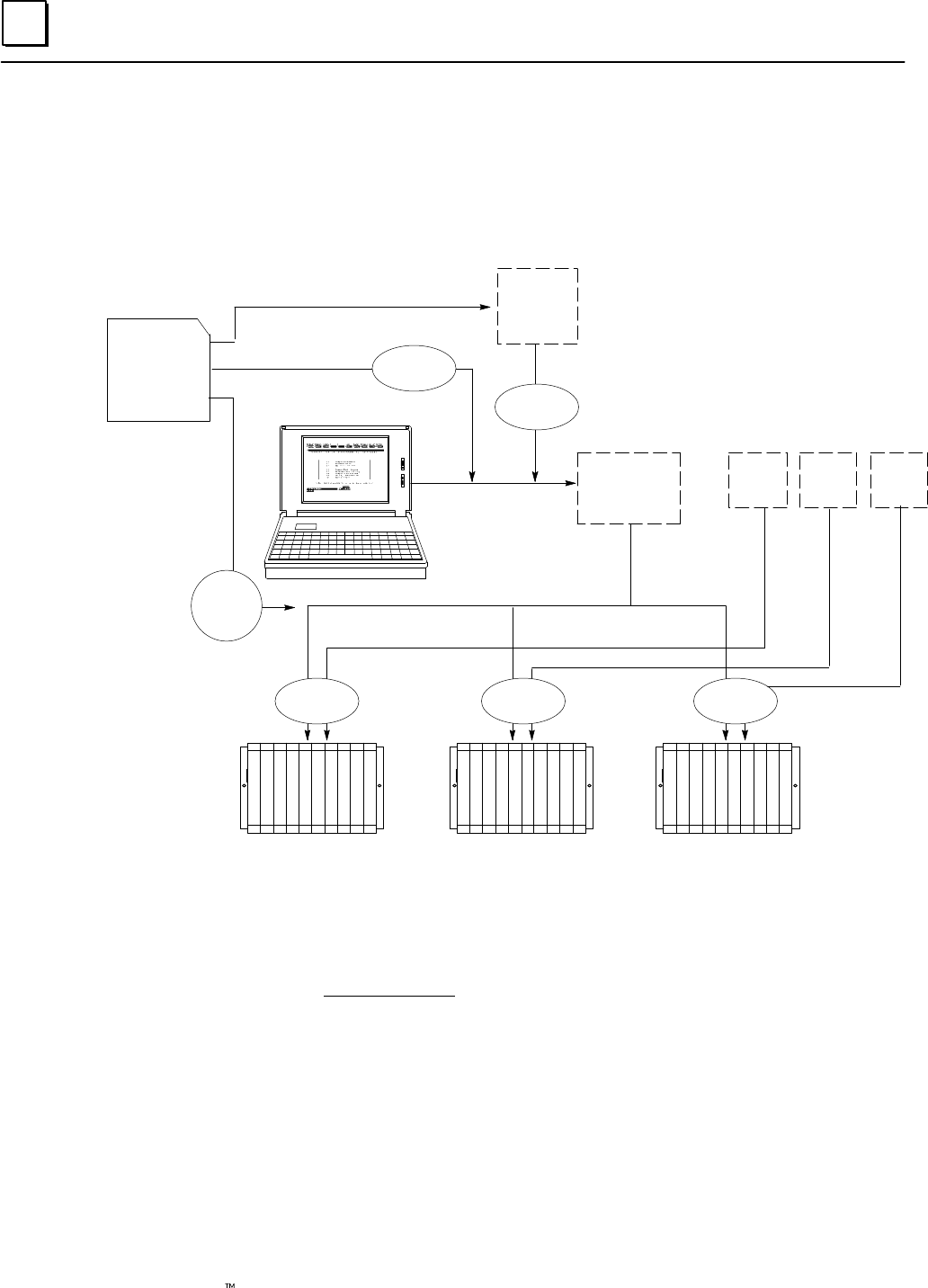
7
7-2 Genius Modular Redundancy Flexible Triple Modular Redundant (TMR) System
User’s Manual – March 1995 GFK-0787B
Programming Overview
The following figure represents the basic GMR programming steps. As explained previously,
the GMR configuration, which assigns I/O reference addresses and produces the G_M_R10
Program Block should be done first.
CONFIG.EXE
GMRxxyy
Download utilities
G_M_R10
Program
Block
CONFIGBCONFIGA
LM90 PROGRAMMING
The
Application
Program
LM90
Librarian
LM90
Copy Folder
PLC A PLC B PLC C
CONFIGC
GMR
Diskette
LM90
Store LM90
Store
LM90
Store
future
program
updates
1. Create a new Program Folder. In the Logicmaster programmer, create a folder with a
new name, such as GMRPROG.
2. Add the GMR system software to the new program folder. Using the Copy Folder
feature of Logicmaster, copy the GMR system software folder GMRxxyy from the
diskette to your new program folder. The application program can now be added to
this folder. It can be newly-created and edited into the folder, or imported via the
library.
3. Using the Logicmaster librarian feature, add the external program block containing
the GMR configuration parameters (G_M_R10) to the LM90 library. Then, use the
Librarian to import G_M_R10 from the Library to the application program folder.
4. After completing the application program and the configuration(s), store them to
the PLCs. Supplying the configuration and program as separate files, as shown
above, makes it easier to perform program updates in the future.

7
7-3GFK-0787B Chapter 7 Programming Information
Program Instruction Set for GMR
The CPUs used for GMR support the all of the following Series 90-70 ladder logic instructions:
Contacts
Any Contact
–| |–
–|/|–
–| ↑|–
–| ↓|–
–[F AULT]–
–|NOFLT]–
–[HIALR]–
–[LO ALR]–
<+>–––
Coils
Any Coil
–( )–
–(/)–
–( ↑)–
–( ↓)–
–(S)–
–(r)–
–(SM)–
–(RM)–
–(M)–
–(/M)–
–––<+>
Bit Operation
AND
OR
XOR
NOT
SHL
SHR
ROL
ROR
BTST
BSET
BLCR
BPOS
MCMP
Conversion
to BCD–4
to BCD–8
to UINT
to INT
to DINT
BCD–4 to
UINT
BCD–4 to INT
BCD–8 to
DINT
Control
CALL
DOIO
SUSIO
MCR
ENDMCR
JUMP
LABEL
COMMENT
SVCREQ
PIDISA
PIDIND
FOR
END_FOR
EXIT
Data Table
TBLRD
TBLWR
LIFORD
LIFOWRT
FIFORD
FIFOWRT
SORT
ARRAY_MOVE
SRCH_EQ
SRCH_NE
SRCH_GT
SRCH_GE
SRCH_LT
SRCH_LE
Data Move
MOVE
BLKMOV
BLKCLR
SHFR
BITSEQ
SWAP
COMMREQ
VMERD
VMEWRT
VMERMW
VMETST
VME_CFG_RD
VME_CFG_WRT
DATA_INIT
DATA_INIT_COMM
Timers
ONDTR
OFDT
TMR
Counters
UPCTR
DNCTR
Links
Horizontal
Vertical
Relational
EQ
NE
GT
GE
LT
LE
CMP
Math
ADD
SUB
MUL
DIV
MOD
SQRT
ABS
SRCH_LE
DATA_INIT
DATA_INIT_COMM
DATA_INIT_ASCII
Use of Do I/O and Suspend I/O
The Do I/O and Suspend I/O program functions can interfere with the output autotest. They
should not be used in any GMR application program.
Programming Restrictions for TÜV Applications
Some of the program instructions listed above can not be used for a GMR system that
will be applied in an Emergency Shut Down (ESD) application for which for a TÜV site
application approval will be sought. See Appendix A for details.
Estimating Memory Usage
The GMR system software version 2.06 uses approximately 318,688 bytes of the CPU’s
memory. To determine how much of the 512 Kbyte memory (IC697MEM735) used on
the CPU788 and CPU789 remains for the ladder logic application program, use this
equation:
Max. User Ladder Logic Application Program Size = 524,288 bytes – 318,688 bytes – User Reference Tables
The size of the User Reference Tables depends on your configuration and actual
application program. See the LM90–70 Programming Software User’s Manual (GFK–0263)
for more information.
Estimating Bus Scan Time
If you want to estimate the bus scan time, see page 4-6 for instructions.
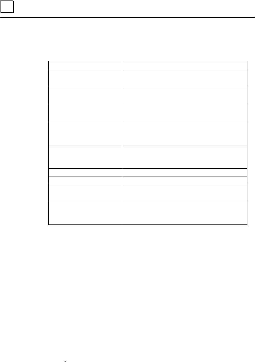
7
7-4 Genius Modular Redundancy Flexible Triple Modular Redundant (TMR) System
User’s Manual – March 1995 GFK-0787B
Reserved References
In a GMR system, the following references are reserved or assigned special functions:
References Reserved For:
%I0001 to %I1024 (788 CPU)
%I00001 to %I12288 (789 CPU)Input Table. Some references are automatically assigned by
the GMR Configuration Software. Others are available for
use, as explained in this chapter.
%Q0001 to %Q1024 (788 CPU)
%Q00001 to %Q12288 (789 CPU) Output Table. Some references are automatically assigned by
the GMR Configuration Software. Others are available for
application use.
%AI0001 to %AImax The length of %AI data (shown at left as max ) is configur-
able. Some references are automatically assigned by the
GMR software. Others are available for application use.
%Rmax– 320+ (66xN) to %Rmx The length of %R data is configurable. At left, the letter N rep-
resents the number of bus controllers on the bus.
The GMR software requires the use of several areas of %R
memory, as detailed in this chapter.
%G0001 to %G0896
%GA0001 to %GA0896
%GB0001 to %GB0896
%GC0001 to %GC0896
The GMR software provides these memory areas for applica-
tion global data transfer. The correct method of program-
ming global data in a GMR system is described in this chap-
ter.
%M12225 to %M12256 System status bits
%M12257 to %M12288 System control flags
%R0001 to %R0256
(defaults: starting reference and
length are configurable)
%R startup initialization data from another online PLC.
References shown at left are the defaults; refer to your GMR
configuration printout for the actual references used.
%R0257 to %R0272
(defaults: starting reference is con-
figurable)
%M startup initialization data from another PLC. Refer-
ences shown at left are the defaults; refer to your GMR con-
figuration printout for the actual references used.
%M defaults to 16 words long.
Memory Write Access
With the exceptions noted above, the following memory areas can be written to if Write
Access is enabled during GMR configuration:
%R Registers
%AI Analog Input Table
%AQ Analog Output Table
%I Discrete Input Table
%Q Discrete Output Table
%T Temporary internal reference bits that are not saved through power loss
%M Internal reference bits that are saved through power loss
%G Global Data memory
%GD Global Data memory
%GE Global Data memory
For discrete (bit) memories: %I, %Q, %T, and %M, the starting reference must be on a
byte boundary 1, 9, 17, etc). Global Data %GA, %GB, and %GC memories are not
available. Those memory areas are used by the GMR system to exchange data (see
above), and cannot be accessed directly.
Page 6-23 describes configuration for setting up Write Access.
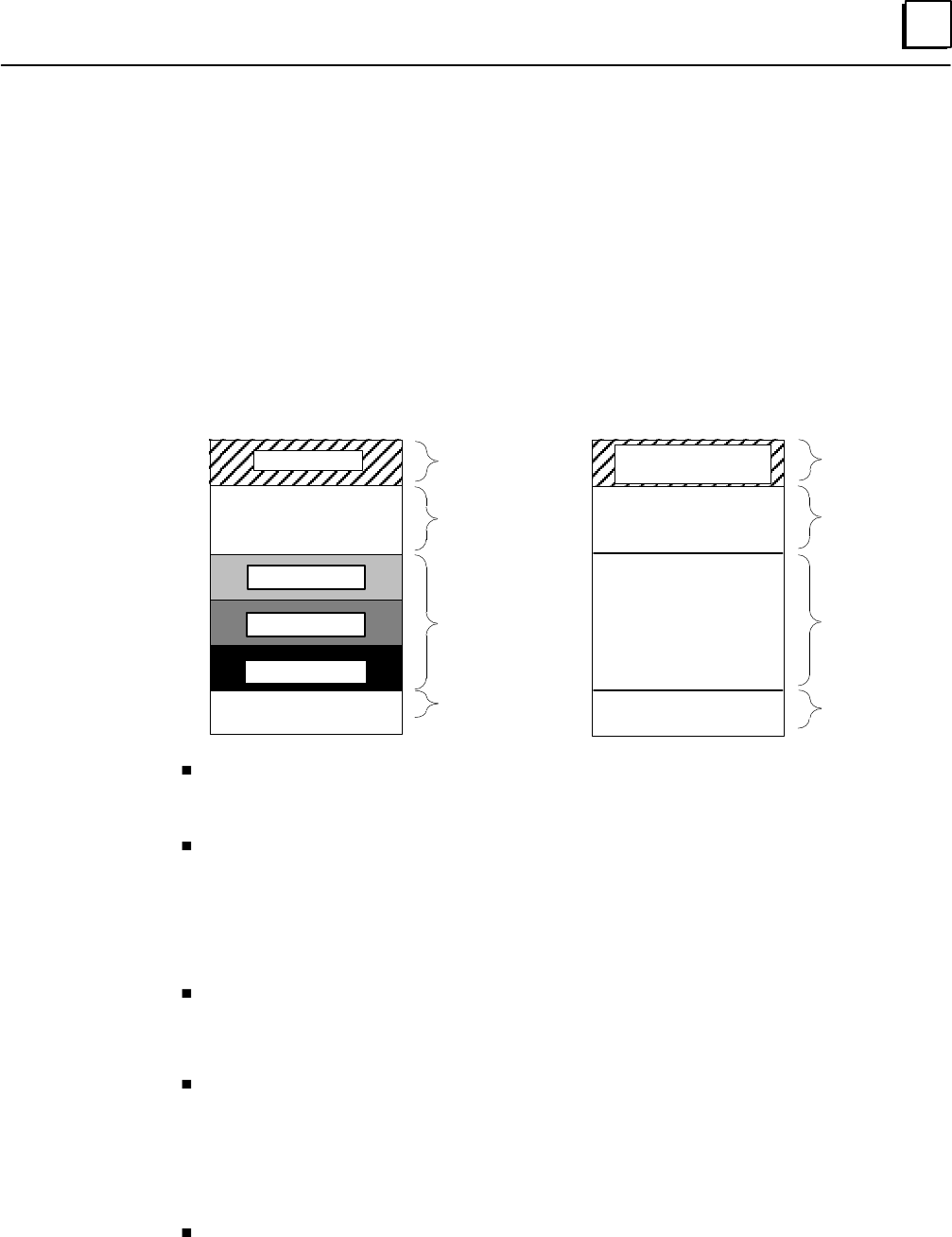
7
7-5GFK-0787B Chapter 7 Programming Information
Input and Output Addressing for GMR
I/O addressing for GMR is unlike a that of conventional Series 90-70 application. In a
conventional application, input and output addresses are assigned sequentially, starting at the
beginning of the Input Table and Output Table. In a GMR application, the GMR software
automatically divides the Discrete Input and Output Tables and the Analog Input Table into
special-purpose areas.
Discrete I/O Addressing
The discrete Input Table and Output Table are divided up into separate areas for redundant
and non-voted data, as shown below.
Discrete Input Table
Voted Inputs
Available for
non-voted Inputs
Bus A inputs
Bus B inputs
Bus C inputs
Reserved inputs
Discrete Output Table
Logical Redundant
Outputs
Available for
non-voted Outputs
Physical Redundant
Outputs
Reserved memory
%I0001
%I1024 or %I12288 %Q1024 or %Q12288
%Q0001
non-voted
I/O
Inputs to PLC
Bus A, B, C
Inputs
Reserved
non-voted
I/O
Outputs from
PLC
Reserved
Output
Memory
Reserved,
Outputs to
Blocks
Voted inputs and logical redundant outputs occupy the beginning of the discrete I/O
tables. Normally, the application program utilizes these inputs and outputs, although it
can also access the rest of the I/O table data if necessary.
Non-voted inputs and outputs occupy the next portions of the Input and Output Tables.
These are the inputs and outputs of blocks that are present in the system either as
non-voted blocks on GMR busses, or on other busses.
The starting address for non-voted data depends on the amount of redundant data, as
explained above. In the same example, if there were 64 voted inputs and 48 logic outputs,
non-voted I/O data would begin at addresses %I0065 and %Q049.
The area of Output Table memory that corresponds to the bus A, B, and C input data in
the Input Table is reserved. The reason this area is reserved is that input blocks used in
redundancy are configured as combination input/output blocks. So the corresponding
output references should not be used for other purposes.
The last part of the Output Table is used for the copied physical redundant output data.
This is the data that is actually sent to the Genius blocks that are included in the GMR
configuration.
The same amount of memory is reserved in the corresponding area of the Input Table. It
is used to allow GMR fault processing to be inhibited on a circuit-by-circuit basis for the
corresponding physical redundant outputs.
The total amount of I/O data available depends on the CPU type. For the model 788 CPU,
there can be a total of 352 physical inputs and outputs or approximately 100 redundant
I/O points. For the model 789, there can be a total of 12288 physical inputs and outputs
(or a maximum of 4096 redundant I/O points).
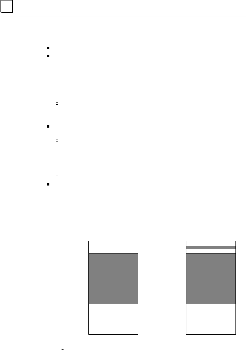
7
7-6 Genius Modular Redundancy Flexible Triple Modular Redundant (TMR) System
User’s Manual – March 1995 GFK-0787B
Discrete I/O Tables: Example
In this very simple example, there are:
a model 788 CPU (with 352 physical I/O).
One output group of four discrete 16-circuit blocks. The application program will use
logical outputs at addresses %Q0001 to %Q0016.
This requires just 16 output references, because the references used by all four blocks
in the group are the same. The references that these blocks will be configured to
respond to are assigned to the 16 bits at the end of the output table. Since the
example CPU is a model 788, the 16 references at the end are:
%Q1009 to %Q1024
The corresponding 16 bits in the Input Table are also reserved for GMR fault
detection disabling. The reserved input references are:
%I1009 to %I1024
One input group of three discrete 32-circuit blocks. The application program will use
voted inputs at addresses %I0001 to %I0032.
The beginning Input Table reference for the data is equal to:
I/O Table length – reserved inputs – (3 X input data length for one group) +1
For the example, this is:
1024 – 16 – (3 x 32) +1 = 913 = %I0913
In the output table, the corresponding area (%Q0913 to %Q1008) is reserved.
One non-voted discrete 16-circuit block.
If configured as a combination block, it occupies references %I0033 to %I0048 in the Input
Table and %Q0033 to %Q0048 in the Output Table. Notice, as shown in the illustration,
that these references begin after the last voted input reference and that output references
%Q0017 to %Q0032 are not used.
The illustration shows where these inputs and outputs would be located in the I/O tables.
Shaded portions represent unused I/O table memory.
Discrete Input Table
Voted inputs = 32
bus A inputs = 32
non-voted
I/O =16
bus B inputs = 32
bus C inputs = 32
Reserved inputs = 16
Discrete Output Table
%Q1024
%Q1008
%Q0913
%I001 – %I0032
%I033 – %I0048
%I0913– %I0944
%I0945– %I0976
%I0977– %I1008
%I1009– %I1024
%Q0001 – %Q0016
%Q0033 – %Q0048
%Q0913 – %Q1008
%Q1009– %Q1024
%Q0001
%I0001
%I0913
%I1008
%I1024
%Q0033%I0033
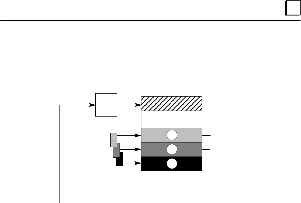
7
7-7GFK-0787B Chapter 7 Programming Information
Analog I/O Addressing
The size of the Analog Input Table is defined during configuration. The maximum size is
8192 analog channels (words). Like the discrete Input and Output Tables, the Analog
Input Table is divided into sections.
Analog Input Table
Voted Inputs
non-voted Inputs
Input
Voting
Logic
A inputs A
B
C
B inputs
C inputs
The voted analog references are assigned starting at %AI0001. The size of the voted
analog input area is determined by the number of voted analog inputs including spares.
Physical input data from analog block groups is located at the end of the Analog Input
Table, in the areas labelled A, B, and C above. Each of these areas is equal in length to the
number of voted inputs at the beginning of the table.

7
7-8 Genius Modular Redundancy Flexible Triple Modular Redundant (TMR) System
User’s Manual – March 1995 GFK-0787B
Example:
An application has sixteen analog input groups (each of which is a 6–input group),
including spares. The total number of analog inputs from these blocks would be:
16 x 6 = 96 words required.
If the Analog Input Table had a configured length of 1024, these inputs would be
located in the table as shown below..
Analog Input Table
%AI0001
%AI1024
Voted Analog Inputs = 96
%AI0096
Bus “C” inputs = 96
%AI0929
%AI0928
%AI0833
%AI0832
%AI0737
%AI0097
%AI0736
Bus “B” inputs = 96
Bus “A” inputs = 96
Available for single
Genius analog inputs
or other use
As with discrete inputs, all of the analog inputs are available to the PLC application program.
Analog Output Addressing
Analog blocks with outputs can be used in a GMR system, but they do not operate in GMR
mode.
They can be configured for Hot Standby CPU redundancy operation. In Hot Standby mode,
an analog block accepts outputs from a bus controller at serial bus addresses 31. If that bus
controller stops sending output data, the block accepts outputs from bus controller 30.
Remember that each PLC in the GMR system normally executes the same application
program.
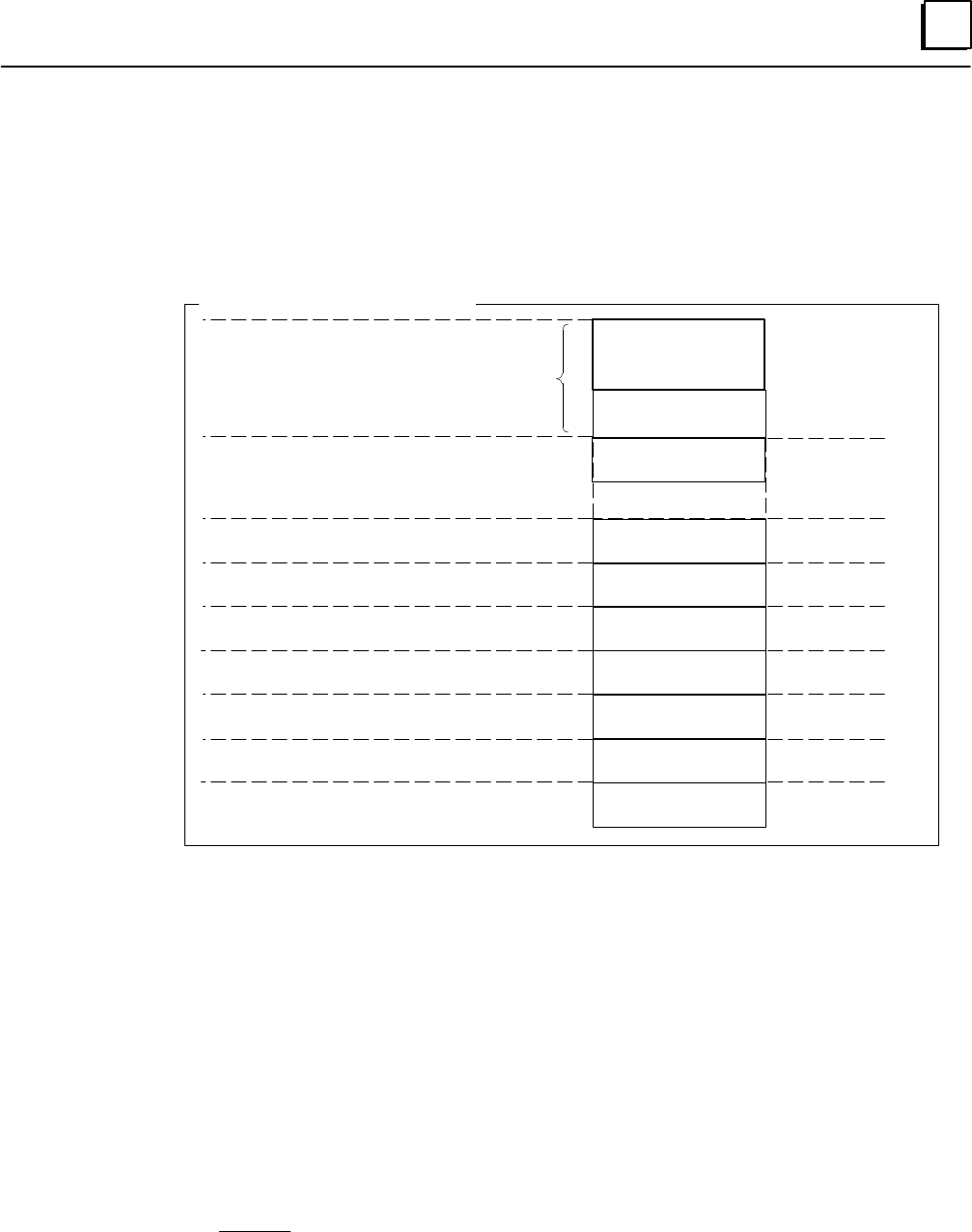
7
7-9GFK-0787B Chapter 7 Programming Information
Register (%R) Memory Assignment for GMR
The GMR software uses several areas of %R memory for specific functions, as
diagrammed below. Only the area labelled “Application Registers” should be used by the
application program. Within that area, a portion is reserved for initialization data, as
explained below.
%R and %M
Initialization Data
Defaults
64 words
64 words
64 words
64 words
64 words
%R Memory Allocation for GMR
66 words
66 words
66 words
%R1
%Rmax–127
%Rmax–191
%Rmax–255
%Rmax–319
%Rmax–385
%Rmax–451
%Rmax–63
%Rmax
%Rmax–128
%Rmax–192
%Rmax–256
%Rmax–320
%Rmax–386
%Rmax–452
%Rmax–64
Global Data to be Sent
Global Data Received from PLC on
Bus a with highest serial bus address
Bus Controller N Interface
Bus Controller N–1 Interface
Bus Controller 1 Interface
Application Registers
%Rmax–320+66xN
Global Data Received from PLC on
Bus a with lower serial bus address
Global Data Received from PLC on
Bus b with highest serial bus address
Global Data Received from PLC on
Bus b with lower serial bus address
.
.
.
Each PLC receives two sets of incoming Global Data from the other PLC(s). Both of these
are placed into %R memory, as can be seen in the diagram. Only one set is copied to %G
memory for access by the application program, however.
Directly ahead of the incoming Global Data in %R memory is a copy of the outgoing
Global Data. This data should be programmed using %G memory, not %R memory. The
GMR software automatically moves the data to the appropriate %R location prior to the
Global Data being sent.
Ahead of the Global Data areas of %R memory are additional areas used by the GMR
software for communications with I/O blocks (for functions such as autotesting and
diagnostics) and with other bus controllers on the bus. The overall length of this area
depends on the number of other bus controllers in the system.
%R Memory Required for Startup Initialization Data
%R and %M initialization data that may be received during startup are stored in %R memory
(the second set of incoming %M initialization data is stored there temporarily at startup).
The GMR Configuration Software default for the beginning of the initialization data is %R0001.
In addition, by default, the configuration software assigns %R0257 as the beginning location
for %M initialization data which is directly after the %R initialization data.

7
7-10 Genius Modular Redundancy Flexible Triple Modular Redundant (TMR) System
User’s Manual – March 1995 GFK-0787B
System Status (%S) References
System status references are pre-defined locations and nicknames. They can be included
in the application program to check for fault-related conditions. For example, status
references can be used to:
Detect forces and overrides.
Monitor the fault tables.
For a complete listing of %S references, see the Series 90-70 PLC Reference Manual.
Monitoring Forces and Overrides
The GMR software cannot detect point forces and overrides, and their use is not
recommended and may affect the results of autotesting. Forces and/or overrides can also
affect GMR voting of inputs and outputs. Therefore, if the system will include the use of
forces and/or overrides, it is important to include application program logic to detect them.
These system status references detect forces and overrides in an individual PLC:
%S0011 OVR_PRE when set, indicates an override in %I, %Q,
%M, or %G memory.
%S0012 FRC_PRE when set, indicates a force on a Genius point.
Monitoring the Fault Tables
These system status references are associated with the fault tables in an individual PLC:
%S0009 SY_FULL when set, indicates that the PLC Fault Table is
full.
%S0010 IO_FULL when set, indicates that the I/O Fault Table is
full.
%SC0010 SY_FLT when set, indicates that an entry has been
placed in the PLC Fault Table.
%SC0011 IO_FLT when set, indicates that an entry has been
placed in the I/O Fault Table.
%SC0012 SY_PRES when set, indicates that there is presently at
least one entry in the PLC Fault Table.
%SC0013 IO_PRES when set, indicates that there is presently at
least one entry in the I/O Fault Table.
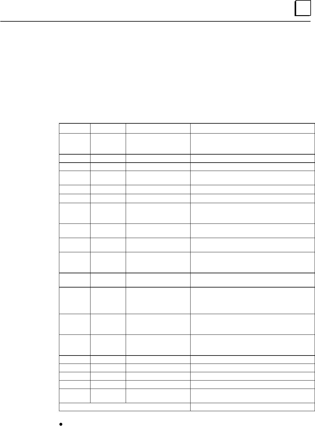
7
7-11GFK-0787B Chapter 7 Programming Information
GMR Status and Control (%M) References
The GMR system software uses several %M references as status or control bits. Status
bits are used by the GMR software to provide information about GMR operations. These
references can be read as needed by the application program. The control bits can be
used by the application program to provide information to the GMR software.
%M Status References
The following table lists the GMR system status flags.
Reference Nickname Name Meaning
%M12225 PLCA PLC Ident is A This is PLC A (all GMR bus controllers =31). For
references %M12225, 26, and 27, only one will be
set in each PLC.
%M12226 PLCB PLC Ident is B This is PLC A (all GMR bus controllers =30).
%M12227 PLCC PLC Ident is C This is PLC A (all GMR bus controllers =29).
%M12228 PLCAOK PLC A is online Meaning depends on the PLC where the flag is
set. See the table on the next page.
%M12229 PLCBOK PLC B is online ”
%M12230 PLCCOK PLC C is online ”
%M12231 INHIBIT Inhibit user application Set by the GMR software at startup, to prevent
execution of the application program until data
initialization is complete.
%M12232 MISCMP#* Init. miscompare at
startup Initializing PLC detects miscompare between
%M (bit) init. data from two online PLCs.
%M12234 SYSFLT#* System fault at startup At startup, communications failure with a GMR
bus controller.
%M12235 SYSFLT System fault Communications failure with a GMR bus con-
troller. This reference is cleared when PLC Fault
Reset is issued.
%M12236 OPDISC O/P discrepancy Output discrepancy. This reference is cleared
when PLC Fault Reset is issued.
%M12237 COLDST* Cold start performed At startup, the initializing PLC detects no other
PLCs online. When the application program
detects this flag has been set, it can initialize any
%M and %R initialization data.
%M12238 IORESIP I/O reset in progress An I/O fault reset is in progress. Bit is On for one
scan when the internal GMR fault tables are
cleared.
%M12239 ATINPRG Autotest in progress An input or output autotest is in progress (not
necessarily initiated by this PLC) the state of this
bit will be the same in all running PLCs.
%M12240 LOGONFT Block logon fault See page 7-17.
%M12241 SIMPLEX Simplex mode One PLC controls the system. •
%M12242 DUPLEX Duplex mode Two PLCs control the system. •
%M12243 TRIPLEX Triplex mode Three PLCs control the system. •
%M12244 IO_SD Any I/O Shutdown
Timer activated At least one of the PLCs has begun timing an I/O
Shutdown.
%M12245 through %M12256, %M12233 Reserved for future GMR use.
*Will only be set at startup if condition occurs.
Only one of these three will be set at a time.
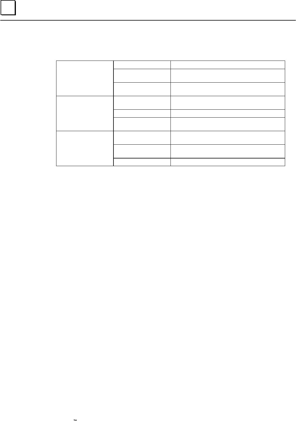
7
7-12 Genius Modular Redundancy Flexible Triple Modular Redundant (TMR) System
User’s Manual – March 1995 GFK-0787B
PLC OK Flags
The meanings associated with the three PLCOK flags are listed below:
At PLC A
PLCAOK PLC A outputs enabled
At PLC A PLCBOK PLC B communications with PLC A healthy
and PLC B outputs enabled
PLCCOK PLC C communications with PLC A healthy
and PLC C outputs enabled.
At PLC B PLCAOK PLC A communications with PLC B healthy
and PLC A outputs enabled
At PLC B
PLCBOK PLC B outputs enabled
PLCCOK PLC C communications with PLC B healthy
and PLC C outputs enabled.
At PLC C PLCAOK PLC A communications with PLC C healthy
and PLC A outputs enabled
At PLC C
PLCBOK PLC B communications with PLC C healthy
and PLC B outputs enabled
PLCCOK PLC C outputs enabled.
Resetting Status Flags
Startup status flags (with asterisks in the table on the previous page) remain set until the sys-
tem is restarted. They can also be reset by the application program. To reset a status flag, enter
0 in its %M reference.
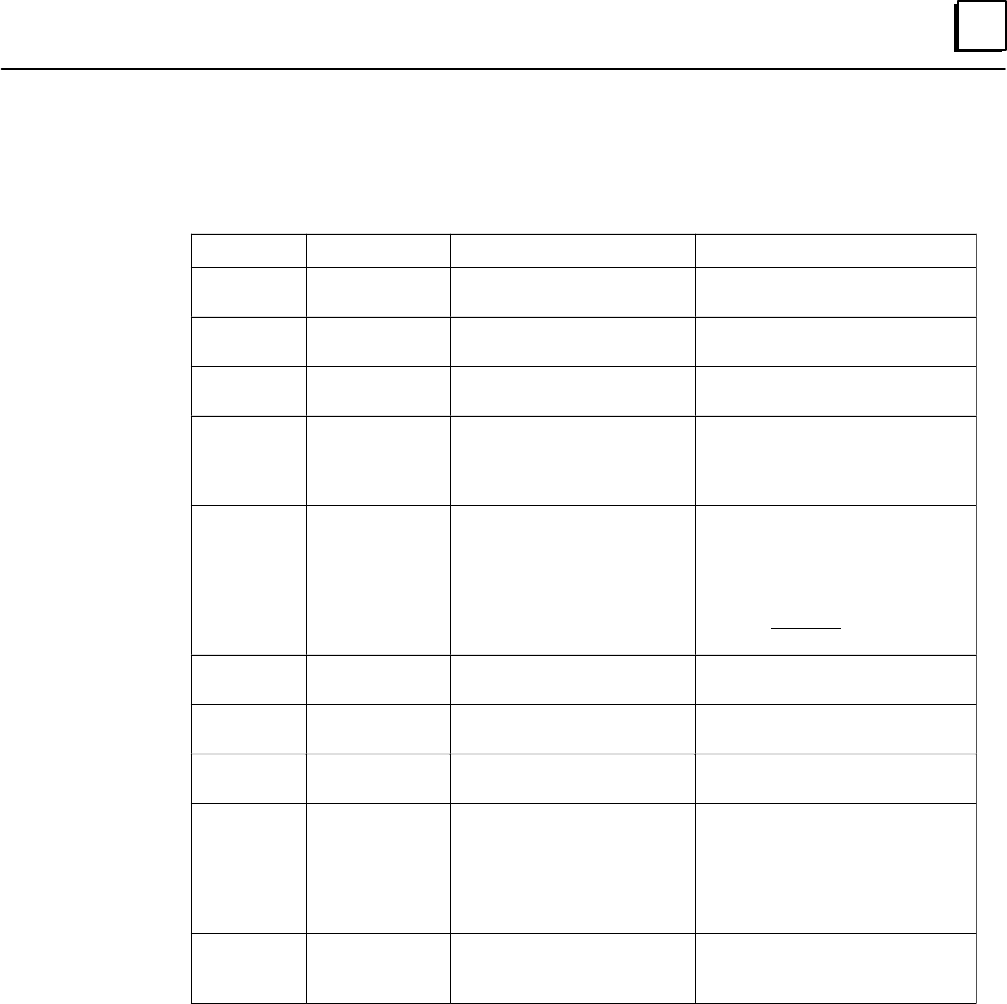
7
7-13GFK-0787B Chapter 7 Programming Information
%M Control References
The application program can use the following %M references to provide information to
the GMR software. The references are located at %M12257 – %M12288.
Reference Nickname Description Meaning
%M12257 CONTINU Continue with initialization
& enable outputs
%M12258 IORES Perform I/O Fault Table clear. See next page.
%M12259 PLCRES Perform PLC Fault Table
clear. At an individual PLC
%M12260 ATMANIN Autotest Manual Initiate Initiates a single autotest (both
input and outout) any time it is
turned on, even if the Autotest
Inhibit bit is on.
%M12261 ATINHIB Autotest inhibit Prevents the “automatic” autotest
(both input and output) from oc-
curring at the Autotest Interval
specified in the GMR Configura-
tion for as long as this bit is On.
Note: it does not prevent an Au-
totest Manual Initate.
%M12262 REPORT Report GMR version / status See description of %M12262 (Re-
port) on page 7-14.
%M12263 FORCLOG Force block(s) to log on See the description of PLC Logon
Control on page 7-17.
%M12264 PLCRESG Clear PLC Fault Tables in all
PLCs. See next page.
%M12265 SDCAN Cancel I/O Shutdown If an I/O Shutdown was initiated
by any PLC, turning this bit On
cancels it and prevents the shut-
down from occurring. If this bit is
set continuously, no I/O Shut-
down will be initiated.
%M12266
to
%M12288
Reserved for future GMR
use.
%M12257 (Continue)
When the application program has computed valid outputs that can be sent to output
blocks, the application program must set control bit %M12257 (CONTINUE) to 1. When
this is done, outputs to the blocks are enabled.
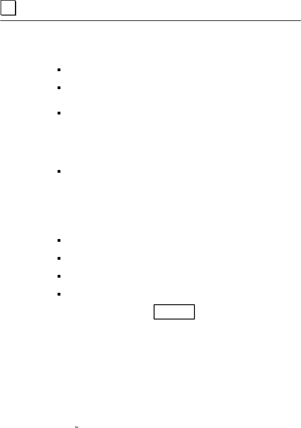
7
7-14 Genius Modular Redundancy Flexible Triple Modular Redundant (TMR) System
User’s Manual – March 1995 GFK-0787B
%M12262 (Report)
When this control bit is turned on, it causes the GMR software to report and record the
following into the PLC Fault Table of the PLC(s) that turned it on:
The GMR Software Version currently running in the PLC. Example:
Application message (10840): GMR Ver:02.06
The GMR Configuration Utility Version used to create the G_M_R10 Program
Block. Example:Application message (10841): Config Util Ver:04.01
The GMR Configuration File (G_M_R10 Program Block) Checksum. Example:
Application message (10842): GMR config CRC:2F4E
This checksum value can be used to verify what configuration file is running in a
GMR PLC. It should be recorded for each different configuration that is created, so it
can be used to determine exactly what configuration file is in a GMR PLC. The GMR
configuration checksum is also recorded in the GMR configuration utility printout of
a configuration.
The 40-character Configuration File Description.
This GMR control bit is infrequently used. It is typical to turn it on manually using
the Logicmaster 90-70 software, although it can also be turned on by the application
program if desired.
Clearing the PLC Fault Tables
Use these %M references to clear the PLC Fault Tables:
To clear the PLC Fault Table in a single PLC, set reference %M12259 to 1 for at least
one PLC sweep.
To clear the PLC Fault Table in all PLCs, set reference %M12264 to 1 for at least one
PLC sweep.
To clear the I/O Fault Table and corresponding fault contacts in all PLCs, set
reference %M12258 to 1 for at least one PLC sweep.
Monitor %M12238 (IORESIP) to determine when an I/O Fault Table reset is complete.
Caution
Do not use the Logicmaster F9 key to clear the Fault Tables.
Fault Table Clearing from the Logicmaster software can be prevented by
keeping it in Monitor mode.
Although the Fault Tables seem to operate as they would in a non-GMR system, they are
actually controlled by the GMR software, not the Logicmaster software. Instead, in a
GMR application, the fault tables must be monitored and cleared from the application
program logic.
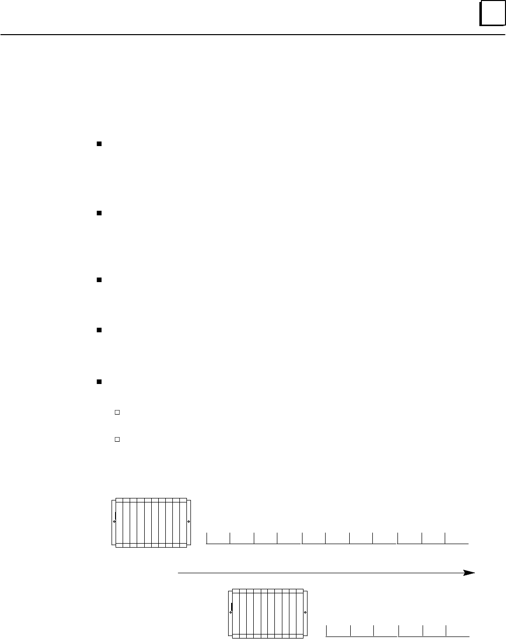
7
7-15GFK-0787B Chapter 7 Programming Information
Programming for Startup
The PLC Subsystem chapter of this book describes the sequence of actions that occur
when the PLCs in a GMR system are started up.
The GMR software in the PLCs only allows one PLC to come online at a time. First, a
PLC determines its ID by reading the serial bus addresses of the GMR Bus
Controllers (PLC A = 31, PLC B = 30, PLC C = 29). It then sets the corresponding
PLC Identification status bit (see page 7-11): %M12225 for PLC A or %M12226 for
PLC B, or %M12227 for PLC C.
While a PLC is initializing, the GMR software sets the Inhibit status flag (%M12231).
This Inhibit flag should be used to prevent the application program from executing
until initialization is complete. Example ladder logic that provides this functionality
is shown on page 7-18. In addition, the PLC’s outputs are disabled. If outputs do not
disable successfully, the GMR software halts the PLC.
If the initializing PLC is PLC C, the GMR software automatically commands any discrete
Genius blocks configured for Hot Standby operation to accept outputs from the PLC at
serial bus address 29. If this function fails to complete successfully, the GMR software sets
the System status flag (%M12234) to 1.
During initialization, a PLC also communicates with the GMR I/O blocks and with Bus
Controllers in other PLCs. If any of these communications fails, status bit %M12234,
which indicates System Failure at Powerup, is turned on. The application program can
use this bit as a permissive for continuing and annunciation.
As each PLC starts up, it checks to see whether another PLC is already online and
sending outputs.
if not, the PLC sets the “Cold Start” flag (%M12237). The application program can use
this flag to initialize the application program data.
If one other PLC is already online, the initializing PLC reads that PLC’s initialization
data (%M and %R). It then sets its own %M and %R initialization data areas to
match. This is shown by the following simplified example:
PLC A starts up
A counter in PLC A starts
1 2 3 4 5 6 7 8 9 10 11
PLC B starts up and
initializes its counter
with PLC A
The counter in PLC B starts
6 7 8 9 10 11
Time

7
7-16 Genius Modular Redundancy Flexible Triple Modular Redundant (TMR) System
User’s Manual – March 1995 GFK-0787B
If both of the other PLCs are already online, the initializing PLC reads the %R (only)
initialization data from the other PLC with the higher serial bus address. It then sets
its own data to match as shown above.
Word type data that will be included in the initialization data exchanged among
the PLCs at startup, such as timer and counter accumulators, should be located
at the top of the configured %R memory space. This is because the last portion
(top) of the configured %R initialization data is copied last. Locating changeable
data at the top of the %R data assures that the most recent values will be
included when the data is copied.
The third initializing PLC also reads any %M (bit) initialization data from both of
the online PLCs , and compares the two sets of data. If they don’t match, the
initializing PLC sets the Miscompare status reference (%M12232) to 1.
When the PLC completes its data initialization, the GMR software clears the Inhibit status
flag (%M12231). At that point, the application program can monitor the startup status
flags, as suggested on the next page, before continuing startup.
When the application program has computed a set of outputs, it must enable
sending outputs to Genius blocks.
The application program enables outputs to the I/O blocks by turning on control bit
%M12257 (the Continue bit). As the example shows, it is important to have this
occur at the end of the program, so the outputs have been solved at least once before
being enabled.
Monitoring Startup Status
The application program should include logic to cause it to begin executing when the Inhibit
flag is cleared to 0. Depending on the needs of the application, the application program can
begin by checking the startup status flags to determine whether, or how, to proceed with the
rest of the logic. See page 7-11. for a complete list of status flags.
The GMR software provides several initialization flags. It can also monitor the application
program %M data for miscompares, and make program execution conditional upon voting of
the data. See below.
The following flags are of particular interest immediately following startup:
COLDST: If this reference has been set to 1, it means the PLC detected
no other PLC(s) online when it started up. The application program
must initialize its own %M and %R initialization data.
MISCMP#: If set to 1, this flag indicates that when the PLC started up,
the other two PLCs were already online and running their application
programs. When the PLC compared the %M initialization data from the
other PLCs, it found a discrepancy.
SYSFLT# : If set to 1, this flag indicates that when the PLC started up, it
experienced a problem trying to communicate with one of the bus
controllers or a Genius I/O block.
Enabling Outputs At Startup
Following initialization, the application program begins to execute. As a result of one or
more sweeps through the logic, output data is generated. However, outputs remain
disabled, and the output data is not sent on the bus.
%M12237
%M12232
%M12234

7
7-17GFK-0787B Chapter 7 Programming Information
Prior to sending the outputs, the application program may check the status flags. If any
are found to be 1, the application program may decide to process the initialized data
before continuing.
When the application program has computed valid outputs that can be sent to output
blocks, the application program must set control bit %M12257 (CONTINUE) to 1. When
this is done, outputs to the blocks are enabled.
If outputs fail to be enabled successfully, the GMR Software sets the System Fault status
flag (%M12235) to 1.
PLC Logon Control
PLC Logon Control prevents output states from inadvertently changing state when a
newly-initialized PLC is put online by the application program. (The application
program turns on the Continue bit: %M12257). Without PLC Logon Control, outputs
have the potential to change state if a PLC just coming online has output states that
differ from those of other PLCs that are already online, due to the output voting done by
each Genius output block group.
PLC Logon Control causes the output states from a PLC that has just come online to be
compared with the voted output states at each output block group. If the states do not
agree for any output block, the block ignores the new output data and effectively keeps
the new PLC offline with respect to that output block. This condition continues until
either the voted output states match for the complete output block or until the Force
PLC Logon control bit (%M12263, FORCLOG) is turned on. A GMR status bit (%M12240,
LOGONFT) is available. That bit indicates if this condition exists with one ore more
output blocks. It is the responsibility of the application program to monitor the
LOGONFT status bit and to turn on the FORCLOG control bit if desired, to cause output
block groups to vote on and respond to output data from all online PLCs.
Note that, if set, the LOGONFT status bit remains set until the I/O fault table is cleared,
by using the IORES control but (%M12258).
Typically, the FORCLOG and IORES control bits are set through the application program
via an operator interface or simple pushbutton wired to an input circuit.
Powerup Note
PLC Logon Control is also in effect for the first PLC in the GMR system to come online.
The first PLC to come online has its output states compared with the voted outputs
currently present at the output block groups. Remember that the output states of each
output block, with no PLCs online, are determined by the output default configuration
(0, 1, or hold last state) for each individual output circuit at each output block. For
example, if output defaults are set to Off (0) and a PLC is put online with the same
outputs already driven to On (1) states, the output block keeps the PLC offline until the
driven output states agree or until the FORCLOG control bit is set, to force the PLC
online with respect to the output block.
Performing I/O Fault Reset
It is very unlikely, but possible, that I/O faults would occur during the initialization
(powerup or stop/start cycle) of one of the GMR CPUs. Faults occurring during the
initialization of a GMR CPU are reported to that CPU. Therefore it is recommended that
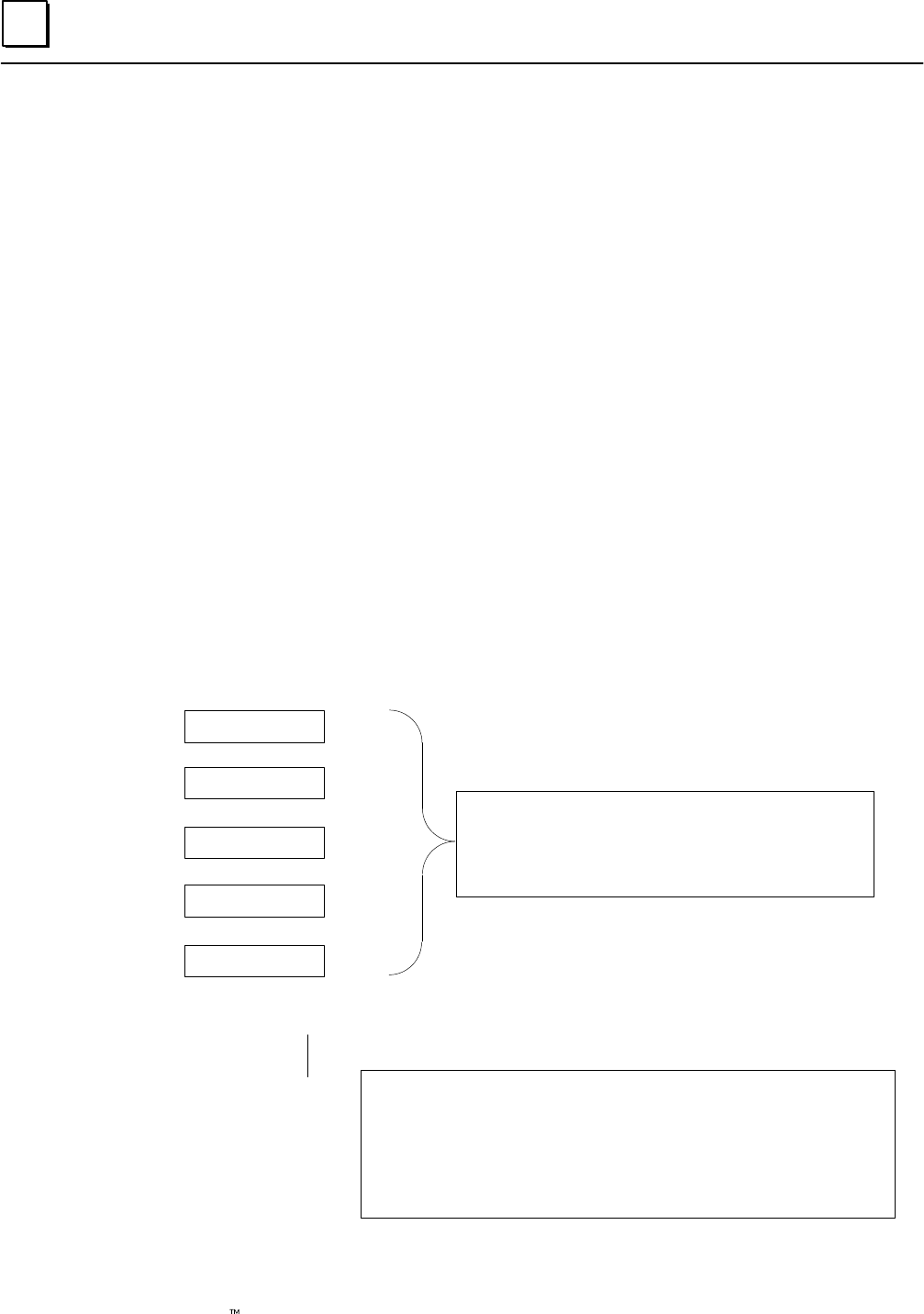
7
7-18 Genius Modular Redundancy Flexible Triple Modular Redundant (TMR) System
User’s Manual – March 1995 GFK-0787B
an I/O Fault Reset be performed when any of the GMR CPUs are initialized, which will
cause any current I/O fault information to be re–reported.
If manual output controls are used in a GMR system and the appropriate GMR Autotest
inhibit inputs are used to block faults created by the manual controls, any standard
Genius type fault (open, overload, short, etc.) is also blocked during the time the inhibit
input is on. It is therefore recommended that after the inhibit input is turned off, an I/O
fault reset be performed, which will cause any current I/O fault information to be
re–reported.
Example Ladder Logic:
The following example shows some typical program startup logic. This is only an
example. You will probably need to modify the logic shown for your application.
|[ START OF LD PROGRAM EXAMPLE ] (* *)
|
|[ VARIABLE DECLARATIONS ] (* *)
|
|[ PROGRAM BLOCK DECLARATIONS ] (* *)
|
|[ START OF PROGRAM LOGIC ]
|
| << RUNG 5 >>
|
|INHIBIT
|——| |—————————————————————————————————————————————————————————————————>> END
|
| << RUNG 6 >>
|
|— CALL IN_CO —
|
| << RUNG 7 >>
|
|— CALL FILTER —
|
| << RUNG 8 >>
|
|— CALL HR_344 —
|
| << RUNG 9 >>
|
|— CALL ANNUN —
|
| << RUNG 10 >>
|
|— CALL DIAGNO —
|
| << RUNG 11 >>
|
|MISCOMP SYSFLT CONTINU
|——|/|————|/|———————————————————————————————————————————————————————————( )———
|
|MAN_COM
|——|/|——————————
|
These Program Blocks represent logic
routines that are appropriate for the
application.
In rung 11, the logic tests for Miscompare and System
Fault. If both are not 1, initialization continues.
An optional parallel input (MAN_COM in this example)
can be used to allow a “manual continue” input to be
supplied by an operator.

7
7-19GFK-0787B Chapter 7 Programming Information
|
| << RUNG 12 >>
|
|IORESIP IORES
|——|# |—————————————————————————————————————————————————————————————————(R)———
|
|
|
|
|
|
|
|
|
| << RUNG 13 >>
|
|LOGONFT FORCLOG
|——|# |—————————————————————————————————————————————————————————————————(R)———
|
|
|
|
|
|
|
|
|
| << RUNG 14 >>
|
|DUPLEX LOGONFT FORCLOG
|——| |—————| |——————————————————————————————————————————————————————————(S)———
|
|TRIPLEX IORES
|——| |——— ————————————————————————————————————————————————————————(S)———
|
| |
|
|
|
|
|
|
|
|
|
|
|
|
|
|
|
|
|
|
|
|–END:
In rung 12, the transition of IORESIP (I/O Reset in Progress) to the Off
state indicates that the requested I/O fault reset has been completed.
This rung resets command bit IORES (I/O Reset) to the Off state.
In rung 13, the transition of LOGONFT (Logon Fault) to the Off state
indicates that the requested I/O fault reset has been completed. This
rung resets command bit FORCLOG (Force Logon) to the Off state.
In rung 14, if the GMR system is in DUPLEX mode (two CPUs are on
line) and a logon fault occurs at an output block, LOGONFT turns on.
This turns on the Force Login (FRCLOG) control bit, which forces the
output block to accept outputs from the newly-online CPU, even if the
output states do not agree with the present voted outputs at the
output block. This logic also turns on the control bit IORES (I/O Reset).
IORES is required to clear the Logon Fault status bit (LOGONFT). This
last action also clears the fault tables in all running PLCs.
The TRIPLEX bit is optional; the need for this bit depends on the
application. If used, it provides the same type of PLC logon control
when a third PLC comes on line.
Caution
Depending on the application, you may prefer to use only the DUPLEX logic shown
above to turn on the FORCLOG (Force Logon) command bit. The purpose of PLC logon
control is to prevent a CPU that is coming online from changing the state of a critical
voted output. Automatic PLC logon is sensible with the DUPLEX status bit, because it
ensures that at least two PLCs are driving output information before outputs that
disagree with the voted outputs are used when a system is initially powered up. The
third PLC coming online has the ability to change an output state if the first two PLCs
are already online and already disagree. Because of this, it may not be suitable to
“automatically” log on the third PLC.

7
7-20 Genius Modular Redundancy Flexible Triple Modular Redundant (TMR) System
User’s Manual – March 1995 GFK-0787B
I/O Point Faults
The GMR system can optionally use the standard Series 90-70 I/O Point Fault references.
The I/O Point Faults feature allocates a bit reference for each potential discrete point
fault and a byte reference for each potential analog point fault.
Note that space for these references is taken from the space available for the application
logic.
With I/O Point Faults enabled, when a fault occurs the fault reference (IO_FLT) is set.
The [FAULT] and [NOFLR] contacts can be used to access the point fault.
Point fault data is written to the references at the start of each CPU sweep, so they
always contain the most recent data.
Enabling I/O Point Faults
The use of I/O point faults requires the following setup during Logicmaster 90
configuration:
A. During CPU configuration, select Memory Allocation and Point Fault Enable (F4)
from the CPU Configuration menu.
B. Change the Point Fault Reference setting from DISABLED to ENABLED.
Programming for I/O Shutdown
When the GMR system diagnoses a discrete I/O fault, it logs the appropriate faults in its
fault tables and set the appropriate fault contacts. For certain types of discrete I/O faults,
the system allows a predefined amount of time for the problem which has caused the
fault to be repaired. If it is not rectified within this period of time, an I/O shutdown of
the I/O which corresponds to the block(s) occurs, unless I/O shutdown is disabled by the
cancel I/O Shutdown control bit (%M12265). I/O shutdown is defined as setting the
affected I/O to its safe state. For more information about I/O Shutdown, please refer to
page 4-18.
To be aware of a pending I/O Shutdown, monitor Status Bit %M12244 (IO_SD).
To completely prevent an I/O Shut Down from occurring set Control Bit %M12265
(SD_CAN).

7
7-21GFK-0787B Chapter 7 Programming Information
Programming for Fault and Alarm Contacts
The GMR system software can optionally utilize the Fault and Alarm contacts capability of the
Series 90-70 PLC to make fault and alarm information available to the application program logic.
Conditions that cause Fault and Alarm contacts to be set are described in the Diagnostics chapter.
Programming for Fault and Alarm contacts is explained on the following pages.
Fault and No Fault Contacts
Fault and No Fault contacts can be used to detect fault or lack of fault conditions on a
discrete (%I or %Q) or analog (%AI or %AQ) reference. They can also be programmed
with the Series 90-70’s built-in fault-locating references (see below). Unless they are used
ONLY with fault-locating references, fault memory for their use must be set up using
the CPU Configuration function of the Logicmaster 90 software.
A Fault contact is programmed as shown below, using the reference address to be monitored
(here, %I0014):
%I0014
[FAULT] %Q0056
( )
A Fault contact passes power flow if the associated reference has a fault. (Fault contacts are
also set if a block logs off the bus.)
A similar contact, called the No Fault contact passes power flow while the associated
reference has no fault.
%I0167
[NOFLT] %Q0168
( )
Clearing Faults Associated with Fault/No Fault Contacts
When used with a %I, %Q, %AI, or %AQ reference, a fault associated with the [FAULT] contact
must be cleared to remove it from the fault table and stop the contact from passing power
flow. Fault contacts are cleared by being reset from the application program, by sending a
command to the GMR software using the %M bit for I/O Reset (%M12258). Clearing such a fault
with a Hand-held Monitor does not remove it from the fault table or stop the contact passing power flow.
Fault-Locating References
Both Fault and No-Fault contacts can be programmed with fault-locating references to
identify faults associated with the system hardware. These fault references are for
informational purposes only. The PLC does not halt execution if one of these reference
faults occurs. For a Genius device, the format of the fault-locating reference is:
M_rsbmm
Where r is the rack number 0 to 7, s is the slot number of the bus controller; b is the bus
number, and mm is the serial bus address of the affected Genius device. For example,
M_46128 represents rack 4, slot 6, bus 1, module 28. For more information about
fault-locating references, please refer to the Logicmaster 90-70 Software User’s Manual.
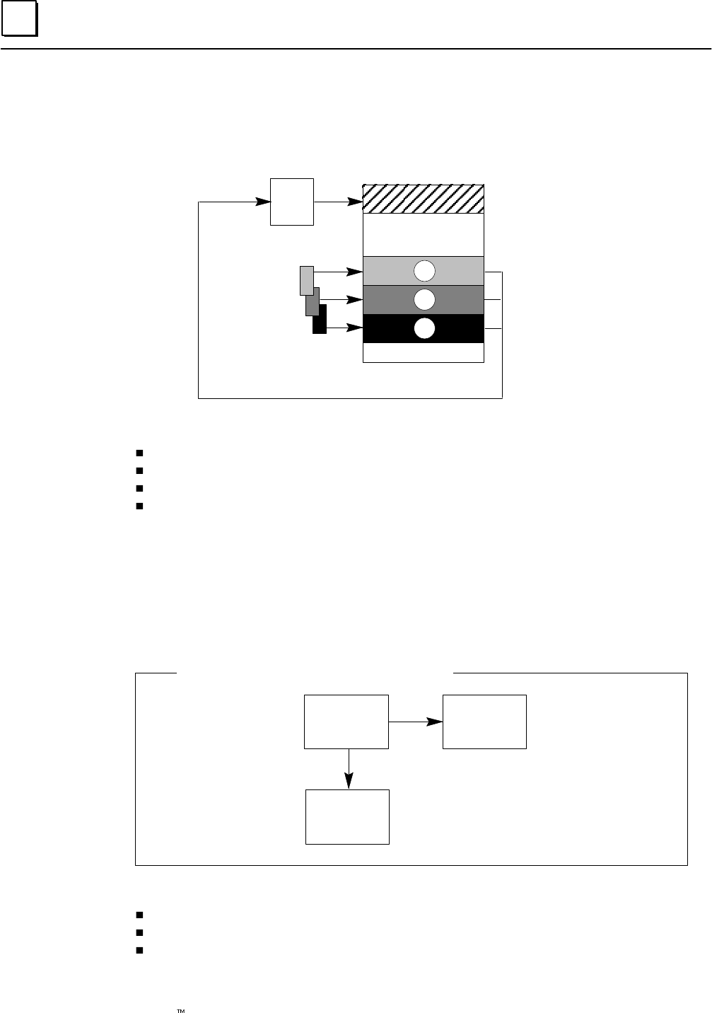
7
7-22 Genius Modular Redundancy Flexible Triple Modular Redundant (TMR) System
User’s Manual – March 1995 GFK-0787B
Discrete Input Fault Contacts for GMR
In the discrete Input Table there are fault contacts associated with each item of voted
input data, non-voted input data, and “raw” data input from bus A, B, and C:
Discrete Input Table
Voted Inputs
Non-voted Inputs
Input
Voting
Logic
Bus A inputs A
B
C
Bus B inputs
Bus C inputs
Reserved inputs
Fault contacts are set for:
Input Genius faults
Input discrepancy faults for A, B, and C inputs
Input autotest faults
Line faults
See page 5-25 for detailed information on conditions that cause fault contacts to be set.
Discrete Output Fault Contacts for GMR
For discrete outputs, fault contacts are associated with logical outputs (outputs from the
application program). These logical references are copied to the physical output references. If
a fault is detected on a physical output, the fault contact associated with that output’s logical
reference is set.
Logical
reference Physical
reference
Fault
contact
Contact References Associated with an Output
Fault contacts are set for:
Genius faults
Discrepancy faults
Autotest faults
See page 5-26 for detailed information on conditions that cause fault contacts to be set.
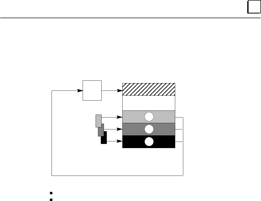
7
7-23GFK-0787B Chapter 7 Programming Information
Analog Fault Contacts for GMR
As for discrete inputs, voted analog inputs have fault contacts associated with both the
raw data inputs and the corresponding voted inputs. Non-voted analog inputs also have
associated fault contacts.
Analog Input Table
Voted Inputs
Non-voted Inputs
Input
Voting
Logic
A inputs A
B
C
B inputs
C inputs
For analog inputs, fault contacts are set for:
Genius faults
Discrepancy faults
For analog outputs, a fault contact is set for any Genius fault, including Loss of Block.
See page 5-28 for detailed information on conditions that cause analog fault contacts to
be set.
Analog Alarm Contacts for GMR
For analog data, there are two additional types of diagnostic contacts that can be used in
the application program, the High Alarm and Low Alarm contacts. These contacts
indicate when an analog reference has reached one of its alarm limits. Alarm contacts are
not considered to be fault contacts.
Alarm contacts for a GMR system are the same as for a conventional system.
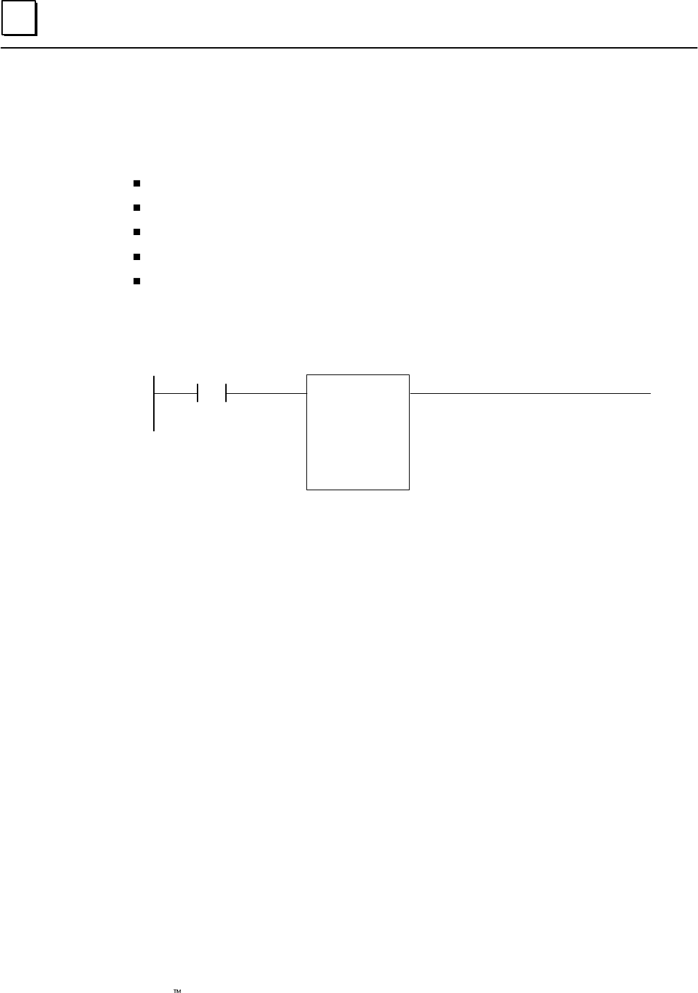
7
7-24 Genius Modular Redundancy Flexible Triple Modular Redundant (TMR) System
User’s Manual – March 1995 GFK-0787B
Reading GMR Diagnostics
The application program can obtain the following diagnostic information from the GMR
system software:
Autotest faults
Discrepancy faults
Genius faults
Point faults
Analog alarms
This information is described in detail in the Diagnostics chapter.
To obtain this information, the application program should CALL an external Program
Block named G_M_R09. Information is read-only; it cannot be written to.
Call G_M_R09
X1
X2
X3
Y1
Y2
Y3
Table
Start
End
Dest
Error
Dummy
( )
Each call to G_M_R09 can access one type of data, as listed in the table on the next page.
Data is returned in bit format. The data length is selected by the Start and End entries.
Parameters for the Call Function
You must specify the following information:
a number representing the type of data to be read. For example, to read
Digital Input Discrepancy faults, you would specify item 11.
the start offset within the area of information specified in the table.
For discrete point faults (input or output faults of any of the types
listed), this is the actual address of the start point to be accessed. For
example, to see if there was an output point fault for %Q00015, you
would enter the value 15 for START.
the end offset within the area of information specified in the table.
the location where the requested information will be placed after it has
been obtained.
the location where the error code will be placed. The error code is
generated if the CALL function fails to execute successfully.
The table on page 7-26 lists error codes may be be read in this location.
not used.
X1: Table
X2: Start
X3: End
Y1:
Destination
Y2: Error
Y3: (dummy)

7
7-25GFK-0787B Chapter 7 Programming Information
Data Table Numbers
Table Contains Range for Start Value Range for End Value
11 Digital Input Discrepancy faults Greater than or equal to the
first digital input address for A,
B, or C.
Less than the start plus the
maximum digital input ad-
dress for A, B, or C.
14 Digital Input Autotest faults start>=1 end<=12228, end<=start
15 Digital Input Genius faults start>=1 end<=12228, end<=start
16 Digital Input Point faults start>=1 end<=12228, end<=start
21 Digital Output Discrepancy faults: PLC A start>=1 end<=12228, end<=start
22 Digital Output Discrepancy faults: PLC B start>=1 end<=12228, end<=start
23 Digital Output Discrepancy faults: PLC C start>=1 end<=12228, end<=start
24 Digital Output Autotest faults start>=1 end<=12228, end<=start
25 Digital Output Genius faults start>=1 end<=12228, end<=start
26 Digital Output Point faults start>=1 end<=12228, end<=start
27 Digital Logon faults (PLC A) First group number required Last group number required
28 Digital Logon faults (PLC B) First group number required Last group number required
29 Digital Logon faults (PLC C) First group number required Last group number required
31 Analog Input Discrepancy faults Greater than or equal to the
first digital input address for A,
B, or C.
Less than the start plus the
maximum digital input ad-
dress for A, B, or C.
35 Analog Input Genius faults start>=1 end<=8192, end<=start
36 Analog Input Point faults start>=1 end<=8192, end>=start
37 Analog Input Low Alarms start>=1 end<=8192, end>=start
38 Analog Input High Alarms start>=1 end<=8192, end>=start
45 Analog Output Genius faults start>=1 end<=8192, end>=start
46 Analog Output Point faults start>=1 end<=8192, end>=start
47 Input shutdown timers (per block)
Returns a single word indicating the shutdown
timer value as seconds of elapsed time. A value
of –1 means a fault exists but the timer has not
started (the Shutdown Cancel bit is On).
High byte contains rack num-
ber (0–7) and low byte con-
tains slot number (1–9)
High byte contains the number
1. Low byte contains the Serial
Bus Address (SBA) of the de-
sired block you want shut-
down information from (0–28)
48 Output shutdown timers (per block)
Returns a single word indicating the shutdown
timer value as seconds of elapsed time. A value
of –1 means a fault exists but the timer has not
started (the Shutdown Cancel bit is On).
High byte contains rack num-
ber (0–7) and low byte con-
tains slot number (1–9)
High byte contains the number
1. Low byte contains the Serial
Bus Address (SBA) of the de-
sired block you want shut-
down information from (0–28)
49 Input shutdown timers (per GBC)
For each SBA, returns a word indicating the
shutdown timer value as seconds of elapsed
time. A value of –1 means a fault exists but the
timer has not started (the Shutdown Cancel bit
is On). A value of 0 means a block does not exist
or has no associated shutdown timer. All output
blocks return the value 0.
High byte contains rack num-
ber (0–7) and low byte con-
tains slot number (1–9) where
the desired Bus Controller is
located.
unused
50 Output shutdown timers (per GBC)
For each SBA, returns a word indicating the
shutdown timer value as seconds of elapsed
time. A value of –1 means a fault exists but the
timer has not started (the Shutdown Cancel bit
is On). A value of 0 means a block does not exist
or has no associated shutdown timer. All input
blocks return the value 0.
High byte contains rack num-
ber (0–7) and low byte con-
tains slot number (1–9) where
the desired Bus Controller is
located.
unused
1000h Configuration text description unused unused

7
7-26 Genius Modular Redundancy Flexible Triple Modular Redundant (TMR) System
User’s Manual – March 1995 GFK-0787B
Error Codes for GMR Diagnostics
The following error codes may be generated by the GMR diagnostics routine (see
page 7-24):
Code Meaning
10908 An attempt was made to read an I/O shutdown timer for an invalid block
10909 An attempt was made to read all I/O shutdown timers for an invalid GBC.
0900hex User I/F – No Error
0902hex User I/F – Incorrect GMR software version
0903hex User I/F – Invalid table number
0904hex User I/F – Unsupported table number
0905hex User I/F – Invalid table offset
0906hex User I/F – Invalid destination address
0907hex User I/F – No Fault Contacts
0908hex User I/F – Bad Block Location
0909hex User I/F – Bad GBC Location
09FFhex User I/F – Disabled
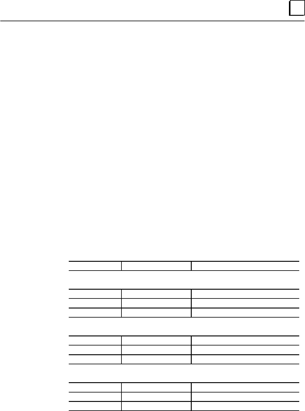
7
7-27GFK-0787B Chapter 7 Programming Information
Programming for Global Data
In a Series 90-70 PLC/Genius system, Global Data is data that is automatically broadcast
by a PLC bus controller, each bus scan.
The GMR software uses this Global Data capability as the vehicle for exchanging system
information between the PLCs. Each PLC provides 8 words of system data to the other PLCs
as Global Data. Because Global Data messages can be up to 64 words in length, up to 56
additional words of Global Data capacity are available for use by the application program.
Since each PLC can broadcast just one Global Data message per bus scan, the system Global
Data and the application Global Data are a sent in the same message.
Global Data for the Application Program
The application program can send Global Data by placing it into %G memory, as
detailed below. Each PLC uses %G0001 through %G0896 to send “application” Global
Data. It is not necessary to use all of the references.
The application program can read Global Data received from the other PLCs from %GA,
%GB, and %GC memory. In addition, each PLC can also read a copy of its own Global Data.
As explained in the PLC chapter of this book, each PLC actually receives two sets of Global
Data from each of the other PLCs. It gives preference to Global Data from the bus designated
bus a. If that data isn’t available, a PLC uses Global Data received from the bus designated
bus b. Under ordinary circumstances, these two sets of data would match. The use of two
busses provides redundant operation in case a bus or bus controller is not available.
The incoming Global Data is data that can be read in %GA, %GB, or %GC memory,
therefore, is the Global Data received on bus a if that data is available. Otherwise, it is
the Global Data received on bus b.
All PLCs %G0001 –%G0896 Global data to be transmitted.
PLC A %GA0001–%GA0896 Copy of transmitted global data.
%GB0001–%GB0896 Data received from PLC B
%GC0001–%GC0896 Data received from PLC C
PLC B %GA0001–%GA0896 Data received from PLC A
%GB0001–%GB0896 Copy of transmitted global data.
%GC0001–%GC0896 Data received from PLC C
PLC C %GA0001–%GA0896 Data received from PLC A
%GB0001–%GB0896 Data received from PLC B
%GC0001–%GC0896 Copy of transmitted global data.
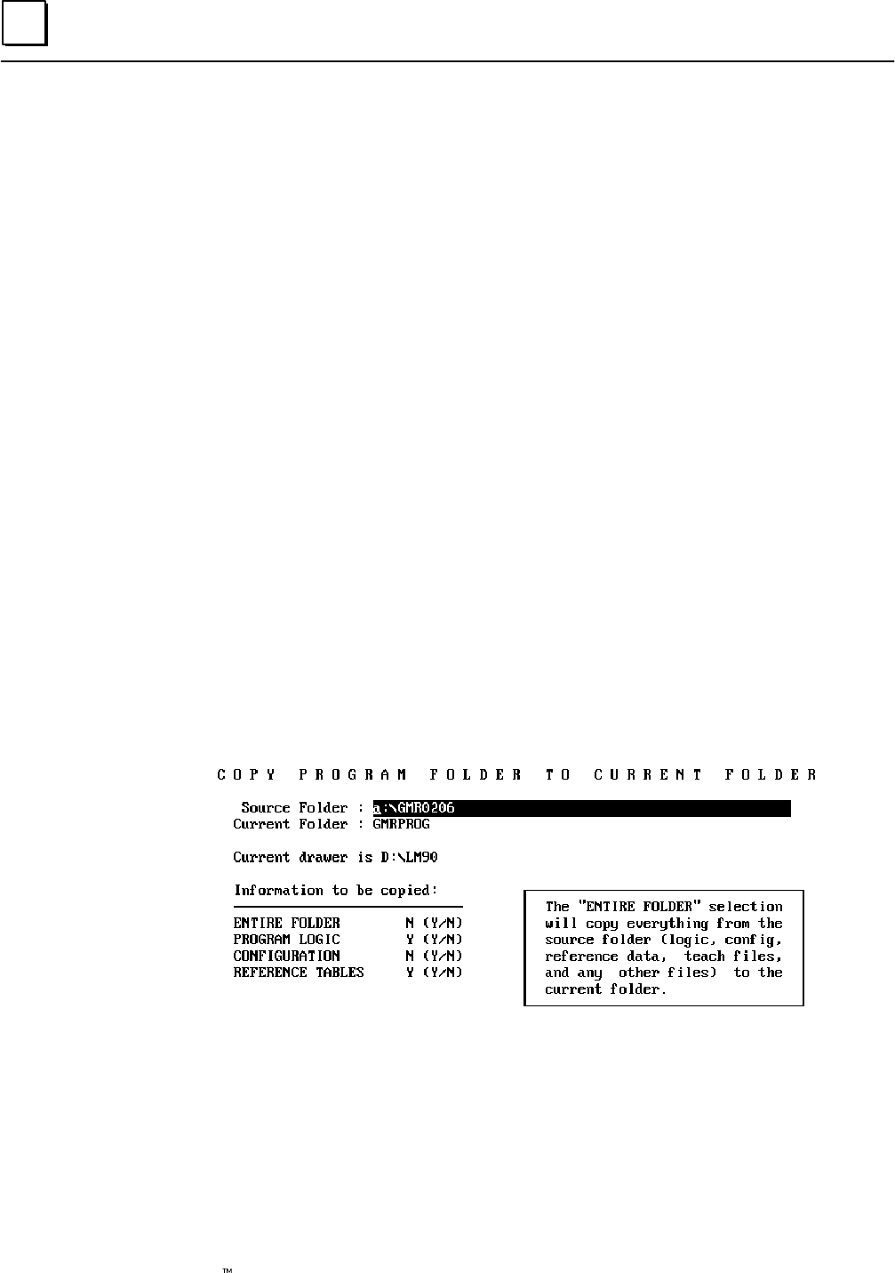
7
7-28 Genius Modular Redundancy Flexible Triple Modular Redundant (TMR) System
User’s Manual – March 1995 GFK-0787B
Adding the GMR System Software to
a New Application Program Folder
The GMR system software provided on the diskette must be added to the folder
containing the application program.
Follow the steps below to add the GMR system software to a new application program
folder.
1. Place the GMR software diskette in a drive where it can be accessed by the
Logicmaster programming software.
2. Enter the Logicmaster programming software and go to the folder functions (F8).
3. Create a new Program Folder (F1).
4. Enter a name for the new folder. Press the Enter key.
5. When prompted that the new name is not that of the current folder, respond “yes”.
6. In the Program Folder functions menu, select F10, Copy Contents of Program
Folder to Current Program Folder.
7. Copy the GMR directory containing the GMR system software to the new folder.
A. For Source Folder, enter the actual name of your GMRxxyy file (for example,
GMR0206).
B. Current Folder should already be selected.
C. For Information to be copied: set Program Logic and Reference Tables only to
yes.
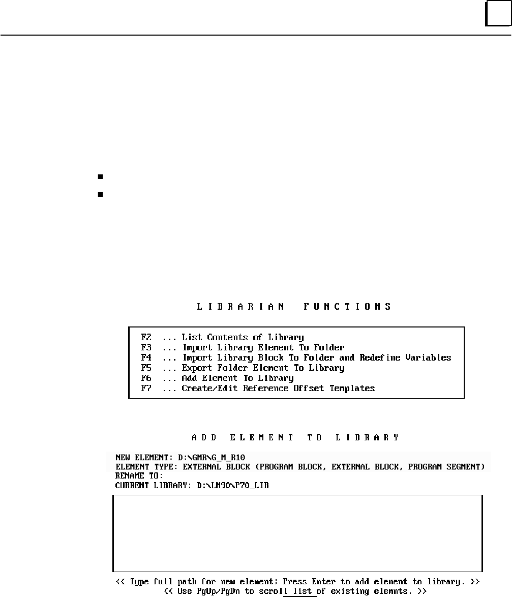
7
7-29GFK-0787B Chapter 7 Programming Information
Adding the GMR Configuration to the Application Program Folder
The GMR configuration software outputs a program block file named G_M_R10.EXE,
which must be added to the folder containing the application program. By default, this
file is located in the GMR Configuration Utility subdirectory.
To add the G_M_R10 program block to the application program folder, use the Librarian
function of the Logicmaster software. There are two basic procedures to complete:
Add G_M_R10 to the Logicmaster librarian.
Import G_M_R10 from the Librarian to the application Program Folder.
Adding GMR_10 to the Logicmaster Librarian
1. In the Logicmaster 90 programming software, select Program Block Librarian.
Press F6 from the Programming Software menu.
The Librarian menu appears:
2. Select F6 (Add Element to Library).
ANNUN DIAGNO FIX G10516 G_M_R10 H2_FLOW N_SIG J1024
MR513
.EXE
3. Type the full path and name of the G_M_R10.EXE file that was created with the
GMR configuration software. You must enter a valid path and filename before you
can exit this field. For example: D:\GMR\G_M_R10.EXE.
4. Select “External Block” as the Element Type. Press the Tab key to display “External
Block” in the Element Type field, as illustrated above.
Do not rename the file. Be sure the selection for “Current Library” is the correct
destination for the file.
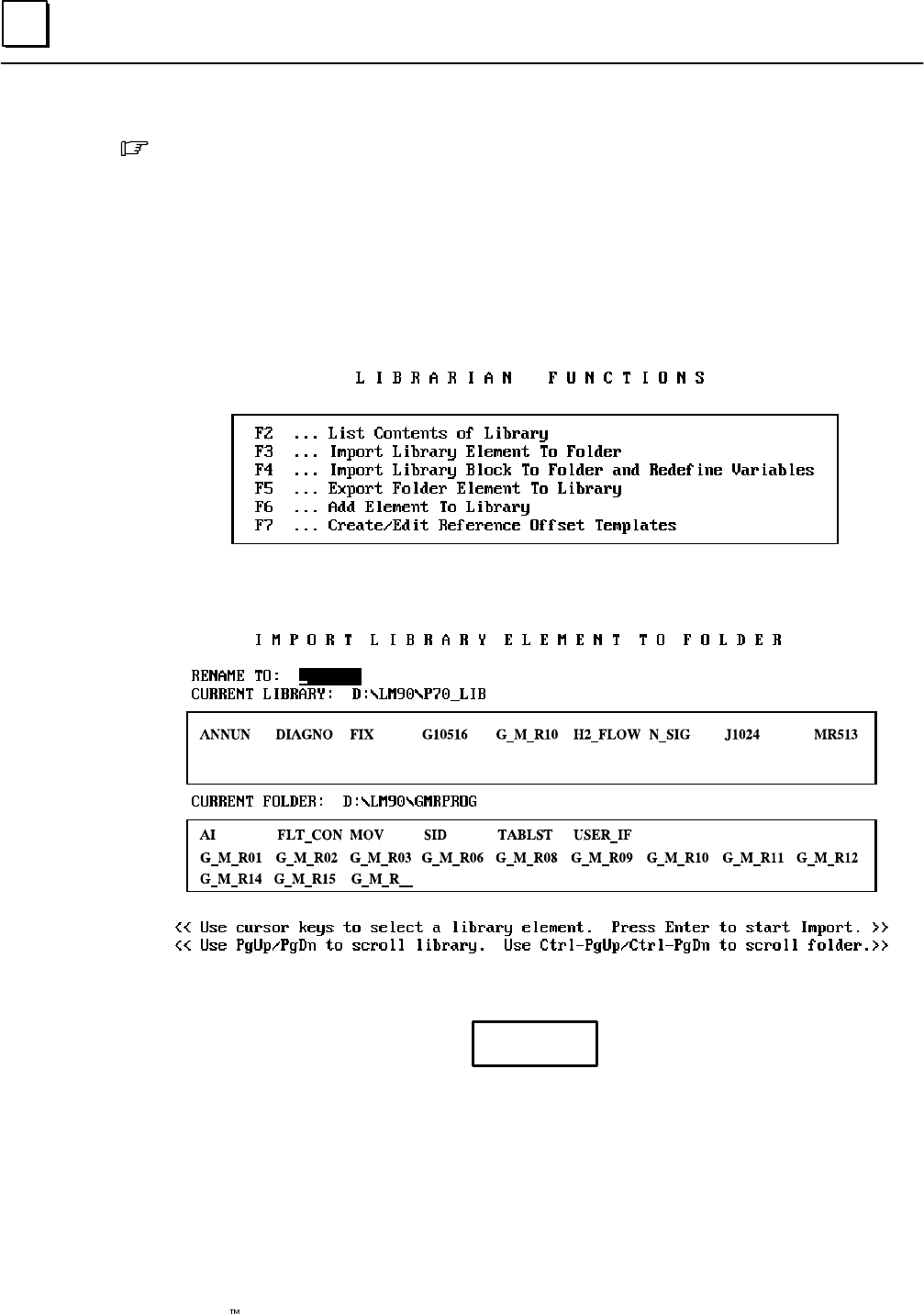
7
7-30 Genius Modular Redundancy Flexible Triple Modular Redundant (TMR) System
User’s Manual – March 1995 GFK-0787B
5. Add G_M_R10 to the library by pressing the Enter key.
6. When prompted for the number of paired input and output parameters, enter 2.
7. Press ESC to return to the Librarian menu.
Importing G_M_R10 from the Librarian to the Application Program
After G_M_R10 has been added to the Librarian, it can be imported to the Program
Folder that contains the application program at any time.
1. From the Librarian menu, select Import (F3).
2. In the upper window on the Import screen, select G_M_R10 from the files
available in the Librarian.
The lower window lists the blocks currently in the selected folder.
Caution
Be sure you want to import the element before you continue. If you
abort an import operation, it is not always possible to completely restore
the folder to its original contents.
3. DO NOT RENAME G_M_R10.
4. Press the Enter key to begin the operation.
5. The original GMRxxyy folder contains a “null” G_M_R10 Program Block. This
causes the prompt “Import G_M_R10, Replacing Element in Folder?” Enter Y for Yes.
Important
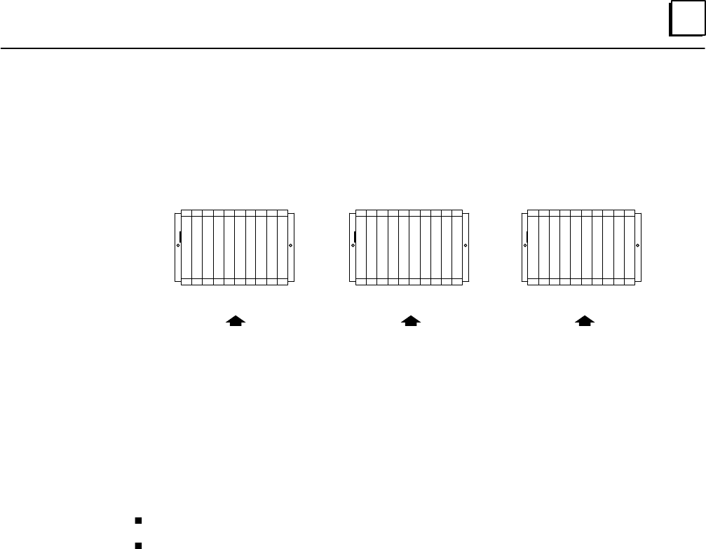
7
7-31GFK-0787B Chapter 7 Programming Information
Storing a Program to the PLC
All redundant PLCs in the GMR system must use the same application program, but
different configurations:
PLC A PLC B PLC C
Program: GMRPROG
Configuration: CONFIGA
Program: GMRPROG
Configuration: CONFIGB
Program: GMRPROG
Configuration: CONFIGC
Supplying the configuration and program as separate files, as shown above, makes it
easier to perform program updates in the future.
Note: The method used for storing a program depends on whether the system has been
configured to permit online changes.
If online changes are NOT permitted, the process shuts down all PLCs.
If online changes ARE permitted, a program can be stored without shutting down
the PLCs. This method requires extreme caution.
It is important to match the configuration to the method (described on the following
pages) you will be using. Regardless of which method you use, the system will be shut
down unless the GMR configuration has online changes enabled. Configuration for
online changes is described on page 6-15.

7
7-32 Genius Modular Redundancy Flexible Triple Modular Redundant (TMR) System
User’s Manual – March 1995 GFK-0787B
Things to Consider when Storing to the PLC from the Programmer
Use the Store function to copy program logic, configuration data, and /or reference
tables from the programmer to the PLC. The Store function copies the program, which
remains unchanged in the programmer. If the PLC program name is not the same as the
folder name, the Store function clears the program from the PLC. The selected data is
then stored from the new program folder.
If the function is password-protected in the PLC, you must know the password in order
to use this function.
Note
In the configuration software, only the configuration may be stored. No
operations on program logic or tables may be performed.
In RUN MODE STORE, you can only store program logic under these conditions:
1. Only blocks that have been changed are stored.
2. The old program executes until the blocks are completely stored, then the new
program begins executing in a “bumpless” manner.
3. The data sizes for %L and %P are based on the highest references used in each
block, regardless of whether the block is called. %L and %P data is increased as these
references are programmed. If a reference to %L or %P) is deleted, the new smaller
size is calculated when the folder is selected.
4. Interrupt declaration changes cannot be made.
5. There must be enough PLC memory to store both old and new program blocks.
6. Timed or event-triggered programs cannot be added or deleted.
7. Control information (scheduling mode, I/O specification, etc...) for programs cannot
be modified.
In STOP MODE STORE, the following can be performed:
1. You can store program logic, configuration data, and/or reference tables from the
programmer to the PLC.
2. If you choose to store logic only and the PLC program name is different than the
program name in the folder, the current logic in the PLC will be cleared and replaced
by the new logic in the current folder. The current configuration data and reference
tables in the PLC are left intact.
3. If you choose to store logic and configuration data and./or reference tables, the logic,
configuration data, and reference tables in the PLC are cleared, and the new data is
stored from the programmer to the PLC.
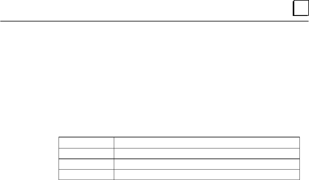
7
7-33GFK-0787B Chapter 7 Programming Information
Using the Store Function
To use the Store function, press Store (F4) from the Program Utility Functions menu. The
Store Program screen appears. The screen shows the currently-selected program folder,
which cannot be changed.
Three types of data can be stored from the programmer to the PLC: program logic,
configuration data, and reference tables. When this screen first appears, only the
program logic is set to Y (yes), which is the default selection. To store all of the data,
change the selection for reference tables and configuration to Y (yes). To store only part
of the data, select N (no) for any of the three types of data you do not want to store.
When a program is being stored to a new CPU for the first time, it is most common to
store all data and select Y (yes) for all three types.
Field Description
Program Logic The ladder logic program and %L and %P data.
Reference Tables The reference tables for the program. except %L and %P data.
Configuration The current configuration.
Note
Annotation files (nicknames, reference descriptions, and comment text)
remain in the folder and are not stored to the PLC.
Logicmaster 90-70 software identifies external blocks with a unique block type when
storing logic to the PLC. If the PLC rejects the external block because it is not the proper
MS-DOS executable file format, the software will display an appropriate error message
based on an error code which is unique to external blocks.
Use the cursor keys to select items, and type in new selections as appropriate. To restore
the original selections while editing this screen, press ALT/A.
The information to be transferred must fit within the configured boundaries of the PLC
(for example, its register memory size).
To begin storing, press the Enter key. The program must be complete, and must not
contain errors in syntax or any instructions which are not supported by the attached
PLC. If there are errors, the Store operation will be aborted.
After a successful Store, the software displays the message “Store Complete”. If a
communication or disk error occurs during the Store process (indicated by a message on
the screen), the selected items are cleared from the attached PLC. Correct the error and
repeat the Store function.
To stop a program Store in progress, press ALT/A if the PLC is in STOP mode. If the PLC
is in RUN mode when the Store begins, you cannot stop the Store process.
To return to the Program Utility Functions menu, press the Escape key.

7
7-34 Genius Modular Redundancy Flexible Triple Modular Redundant (TMR) System
User’s Manual – March 1995 GFK-0787B
Storing a Program to the PLC:
the System is NOT Configured for Online Changes
If the GMR system is configured not to allow online changes, the PLC must be placed in
Stop mode to store a program or make a change to the GMR system.
Storing an Identical Program Following CPU Replacement
If a PLC is to be stored with an identical program, following replacement of a faulty
CPU, then only the PLC to be stored to needs to be placed in Stop mode. The other PLCs
in the system can remain online, providing output control.
When the new PLC is switched to Run/Enable mode, the GMR software compares its
program checksum with that of the other online PLCs while it is initializing.
Storing a Revised Program
If a PLC is to be stored with a program that is not exactly the same as the program
running in the other PLCs, then all PLCs must be stopped, and the same program must
be stored into each.
The GMR software diskette includes a special utility that can be used to facilitate storing
an updated application program in a system that includes SNP (serial network protocol)
communications between PLCs. This utility is described on the following pages.
If the system does not include SNP communications, then the update must be done
manually.

7
7-35GFK-0787B Chapter 7 Programming Information
Using the Program Download Utility
If the redundant PLCs are linked by an SNP network, you can use the Download utility
provided on the GMR software diskette when making future application program
updates. The Download utility:
1. works with the Logicmaster 90 programming software.
2. stops each of the PLC CPUs, with outputs disabled.
3. stores the updated application program to each of the CPUs.
The Download utility assures more efficient, accurate downloading. However, its use is
optional.
The Download utility includes three files:
the download utility file itself, named KEY0.DEF.
two files named UPLC and LM_KEYS.LST that can be used to edit the PLC IDs used
by the download utility.
By default, the download utility requires the IDs PLCA, PLCB, and PLCC. If your PLCs
use those PLC IDs, you can use the utility with modifying it. If your PLCs use other PLC
IDs, you can customize the utility as described on the next page.
Using the Download Utility with the Default PLC IDs
For PLCs with the IDs PLCA, PLCB, and PLCC, the download utility can be used as is:
1. Using DOS, copy the download utility file KEY0.DEF from the GMR software
diskette to the folder that contains the application program. This can be done at any
time.
2. When you are ready to store an updated application program to the redundant
PLCs, go to the Logicmaster 90 main programming menu.
3. To begin the store operation, from the main menu screen, press the ALT and 0 keys
at the same time. For each redundant PLC in sequence, the software will prompt:
Press the Space Bar to Continue
4. When you press the Space Bar, the PLC is put into Stop mode with its outputs
disabled.
5. With all PLCs stopped, the software again prompts:
Press the Space Bar to Continue
6. For each PLC, when you press the Space Bar the utility stores the updated
application program and places the PLC in Run mode with its outputs enabled.
7. After all PLCs have been restarted, the Logicmaster 90 main menu returns.

7
7-36 Genius Modular Redundancy Flexible Triple Modular Redundant (TMR) System
User’s Manual – March 1995 GFK-0787B
Customizing the Download Utility for Other PLC IDs
For PLCs with other PLC IDs, you need to edit the file KEY0.DEF before adding it to the
Program Folder in Logicmaster.
1. Install the GMR software diskette in your computer’s diskette drive.
2. At the DOS prompt, log onto that drive.
3. Copy the Download utility files from the diskette to your fixed disk drive:
UPLC.EXE Update PLC Names utility
LM_KEYS.LST List of keynames required by the Download utility
KEY0.DEF Download utility file
4. Log onto that fixed disk drive. At the DOS prompt, enter:
UPLC
5. At the prompt, enter the PLC ID you want to use instead of PLCA. The name can be
from 1 to 7 characters long. It can include any alphanumeric characters and the
following special characters:
–, @, _, #, $, %, <, >, =, +, &.
6. Continue and enter new names for PLCB and PLCC.
7. The software creates a new Download utility file named NEW.DEF. When it is
completed, it displays:
Processing Complete
8. Copy the new file to the Logicmaster Program Folder containing the application
program. Rename the file to KEY0.DEF during the copy.
For example:
C: COPY NEW.DEF C:\FOLDERS\PROGRAM\KEY0.DEF
9. The edited file can now be used as described on the previous page.

7
7-37GFK-0787B Chapter 7 Programming Information
Storing a Program to the PLC:
the System IS Configured for Online Changes
For a system configured to allow online changes, the following sequence illustrates how
an online ladder logic program change could be done in a triplex CPU System. System
configuration changes are not intended to be done online. (Online ladder logic changes
are intended for system debug and commissioning).
1. Using the Logicmaster 90-70 Programming Software in the Monitor mode, make a
direct or multidrop connection to PLC “A”.
2. Change the Logicmaster 90-70 programmer mode to the Online mode, and change
the CPU Memory Protect keyswitch to the unprotected position (the Mem Protect
LED will be off). Make the run mode store, single word online change, or block edit
at PLC A. A “Program Changed A” message is logged into the PLC Fault Table at PLC
A. “Program Changed A” is logged into the PLC Fault Table of PLC B and PLC C. If
the change affects the state of any outputs, the discrepant outputs are “voted out” at
the output blocks by the 2 out of 3 voting algorithm. The appropriate output
discrepancy error(s), if any, are logged at all three PLCs..
3. Change the CPU Memory Protect keyswitch to the protected position (the Mem
Protect LED is on).
4. Using the Logicmaster 90–70 Programing Software, make a direct or multidrop
connection to PLC B.
5. Change the CPU Memory Protect keyswitch to the unprotected position. Make the
same program change at PLC B. “Program Changed B” is logged into the PLC Fault
Table of PLC B. If the change affects the state of any outputs, these outputs would
now agree for PLC A and PLC B, and the output state(s) from PLC C are “voted out”
at the output blocks by the voting algorithm. The appropriate output(s) from PLC C
will now be discrepant and the appropriate discrepancy and the appropriate
redundancy error(s) are logged at all three PLCs.
6. Change the CPU Memory Protect keyswitch to the protected position (the Mem
Protect LED is on).
7. Using the Logicmaster 90–70 Programing Software, make a direct or multidrop
connection to PLC C.
8. Change the CPU Memory Protect keyswitch to the unprotected position. Make the
same program change at PLC C. “Program Changed C” is logged into the PLC Fault
Table of PLC C. If the change affects the state of any outputs, these outputs would
now agree for PLC A, PLC B, and PLC C, and the output state(s) should no longer be
discrepant. The “Program Changed C” messages can now be cleared along with any
output discrepancy errors that were logged due to the program change.
9. Change the CPU Memory Protect keyswitch back to the protected position (the
Mem Protect LED is on).
Notes
After many online changes are made, fragmentation of memory may occur. That will
prevent subsequent online changes from being made. To make changes, place the

7
7-38 Genius Modular Redundancy Flexible Triple Modular Redundant (TMR) System
User’s Manual – March 1995 GFK-0787B
CPU being stored to in Stop mode and store a complete program from the
programmer to the PLC. This cleans up any fragmentation that exists and enables
future online changes.
If an online program change is made to a single PLC and subsequently deleted
before the same change is made to the other PLCs in the system, it is possible that
the program checksum will not match, even though the programs in the CPUs
appear to be the same. Logicmaster 90-70 may also indicate “Logic Not Equal” when
connected to a PLC in which the change/deletion was not made. To recover from this
condition, a “run mode store” may be required at the PLCs in which the deletion
was not made.
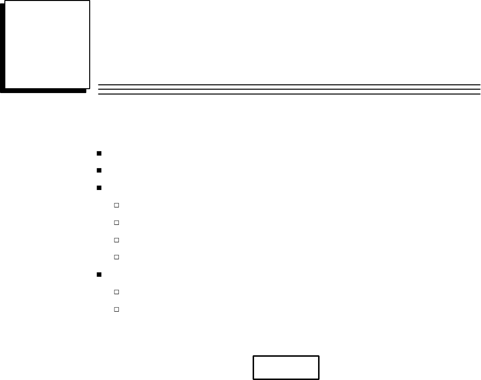
8section level 1 1
figure bi level 1
table_big level 1
8-1
GFK-0787B
Chapter 8Installation Information
Genius Bus Connections
Termination Boards
Input Wiring
Single Sensor to Three Blocks (Triple Bus)
Three Sensors to Three Blocks (Triple Bus)
Block Wiring for a 16-Circuit Block in an Input Group
Block Wiring for a 32-Circuit Block in an Input Group
Output Wiring
Block Wiring for a 16-Circuit, Four-block Output Group
Block Wiring for a 32-Circuit, Four-block Output Group
Note
The information in this chapter is intended only to supplement the installation
instructions in the Series 90-70 PLC and Genius I/O Manuals and datasheets.
Those documents should be the primary references for installation of any GMR system.
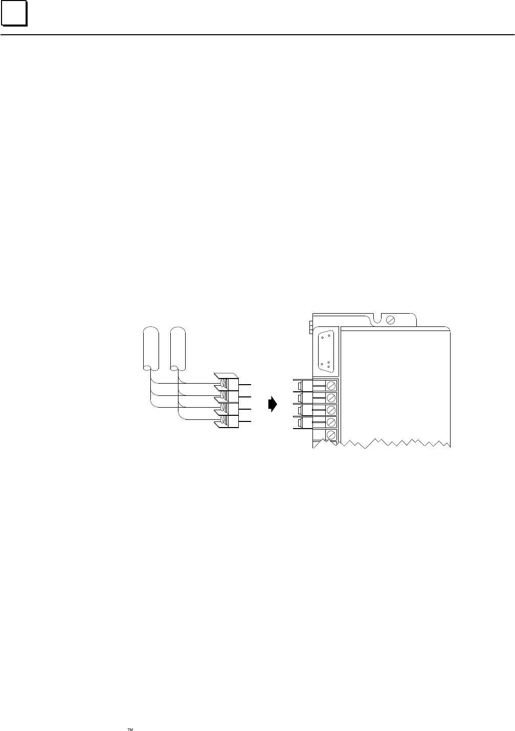
8
8-2 Genius Modular Redundancy Flexible Triple Modular Redundant (TMR) System
User’s Manual – March 1995 GFK-0787B
Genius Bus Connections
When planning and installing a Genius bus, it is extremely important to follow the
guidelines given in the Genius I/O System and Communications User’s Manual. That manual
describes correct cable types, wiring guidelines, bus length, bus termination, baud rate,
and bus ambient electrical information.
In GMR system, “GMR busses” can operate at any baud rate with the following
restrictions:
D. All busses in a group must use the same baud rate.
E. Each individual GMR bus must have a scan time of 60 milliseconds or less.
Bus cable connections to a Genius block in a GMR system should be made in such a way
that a block’s terminal assembly can be removed from the bus during system operation
without “breaking” the bus and disrupting communications.
To do that, the bus can be installed at each block using an intermediate connector, as
shown below.
I
N
O
U
T
S1
S2
SHLD IN
SHLD OUT
S1
S2
SHLD IN
SHLD OUT
An alternative method, but somewhat less desirable, is to solder together the
corresponding wire ends before inserting then into the block’s terminals. If such
soldered wires are removed while the system is operating, it is important to cover the
ends of the wires with tape to prevent shorting the signal wires to one another or to
ground.
Both of these installations allow a block’s terminal assembly to be removed while
maintaining data integrity on the bus.
When blocks are connected to the bus in this manner, field wiring to the blocks should
also provide a means of disconnecting power to individual blocks.
Termination Boards
Termination boards that will make it easier to integrate Genius blocks into redundant
groups (4-block output groups or 3 or 2 block input groups) are currently being
developed by a third-party supplier. Please contact your GE Fanuc Sales representative
for more information about these GMR Termination Boards.

8
8-3GFK-0787B Chapter 8 Installation Information
Input Wiring
Calculating Voltage Drops on Tristate Inputs
It is important to consider the field wiring runs required for devices configured as
tristate inputs. Devices that are powered by 24V DC will have a voltage-reducing
component inserted at the field device to provide an input threshold range for three
states. The table on page 2-7 shows appropriate ranges. Wiring runs can reduce the
voltage at the input block terminal further, to an inoperable level, depending on the
length, conductor, and gauge. Isolation diodes placed before the terminal on the input
will also drop the voltage.
Most applications do not have limitations created by these factors. However, to ensure
that all input state operations are indicated correctly, calculations should include the field
signal voltage, the wire resistance times the length and the voltage drop in any barriers
or isolation devices, to determine the actual voltage present at the input terminal.
Additional information about input blocks is located in the Genius I/O Discrete and Analog
Blocks User’s Manual (GEK-90486-2).
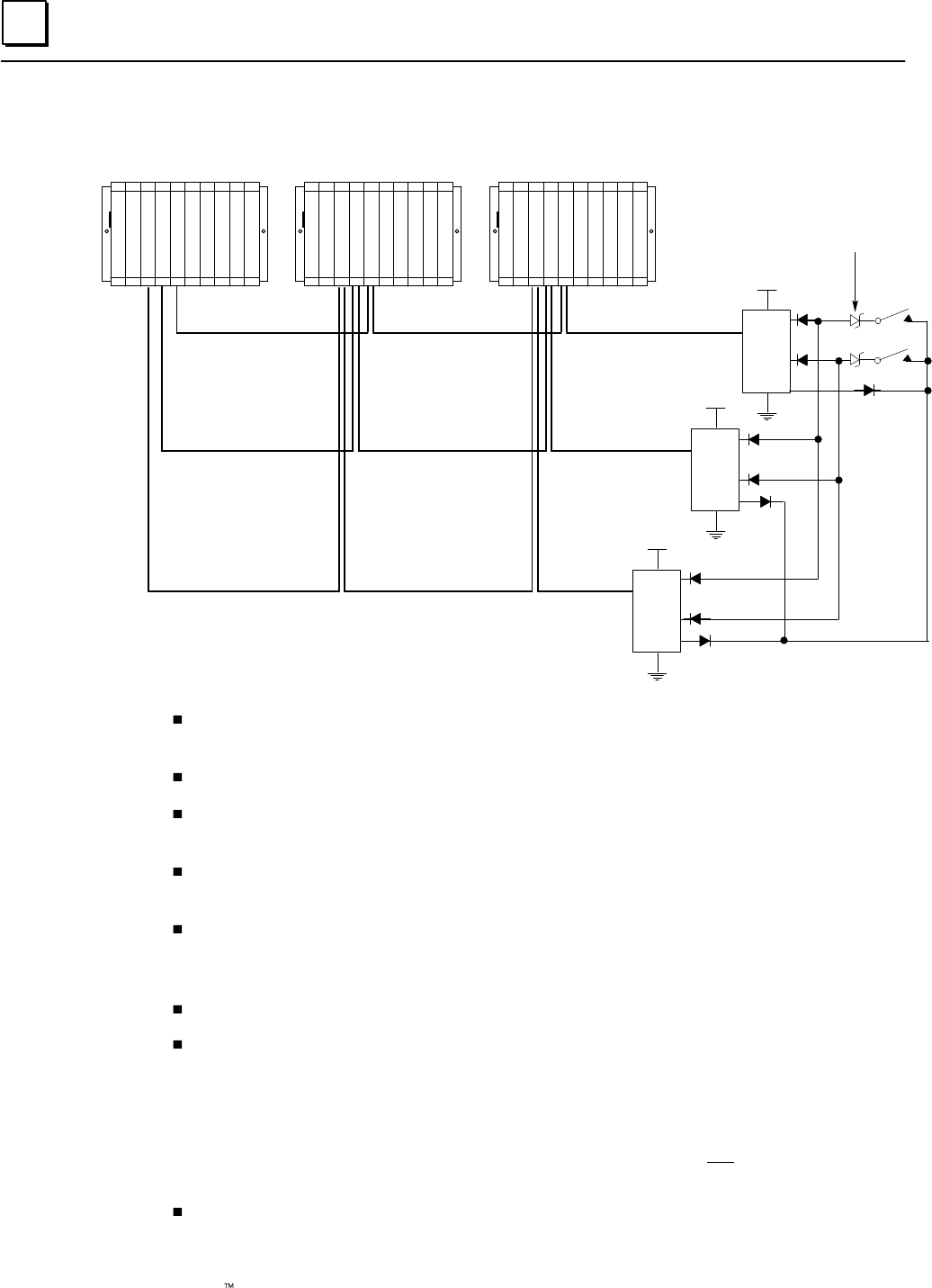
8
8-4 Genius Modular Redundancy Flexible Triple Modular Redundant (TMR) System
User’s Manual – March 1995 GFK-0787B
Single Sensor to Three Blocks (Triple Bus)
DC+
I1
I15/32
O16
DC+
I1
I15/32
O16
DC+
I1
I15/32
O16
Input 1
Input 15 or 32
C
P
U
G
B
C
C
G
B
C
A
G
B
C
B
C
P
U
G
B
C
A
G
B
C
B
G
B
C
C
C
P
U
G
B
C
A
G
B
C
B
G
B
C
C
P
SP
SP
S
PLC A PLC B PLC C
6.2V Zener Diodes for
Line Monitoring (optional)
6.2 volt Zener diodes are used for optional line monitoring on circuits configured as
tristate inputs. This option is only available with 16-circuit DC blocks.
All blocks in an input group must have the same number of circuits (either 16 or 32).
On either 16-circuit or 32-circuit blocks, circuit 16 is used as an output if the block
group is configured for input autotesting.
On any block, circuits that are not configured as part of the GMR input group can be
used as non-redundant inputs or outputs.
If redundant power supplies are used on the blocks, they should be diode “ORed”
power supplies providing a common power source for all blocks in the group.
Different groups may use different power sources.
All blocks in the input group must be assigned the same serial bus address.
If the block group is configured for input autotesting, it must be wired appropriately,
Each input that is configured (by the GMR Configuration Software) to be autotested
must have its input device wired to receive power from output Q16 of the block
group, as shown above. The Q16 outputs from each block are “diode–ORed”
together to function as the power feed for autotested input devices. Input devices
for input circuits that are not configured for autotesting should not be wired to the
power feed output.
Isolation diodes must also be wired as shown above for any input to be autotested.
The suggested diode is 1N5400 or equivalent.
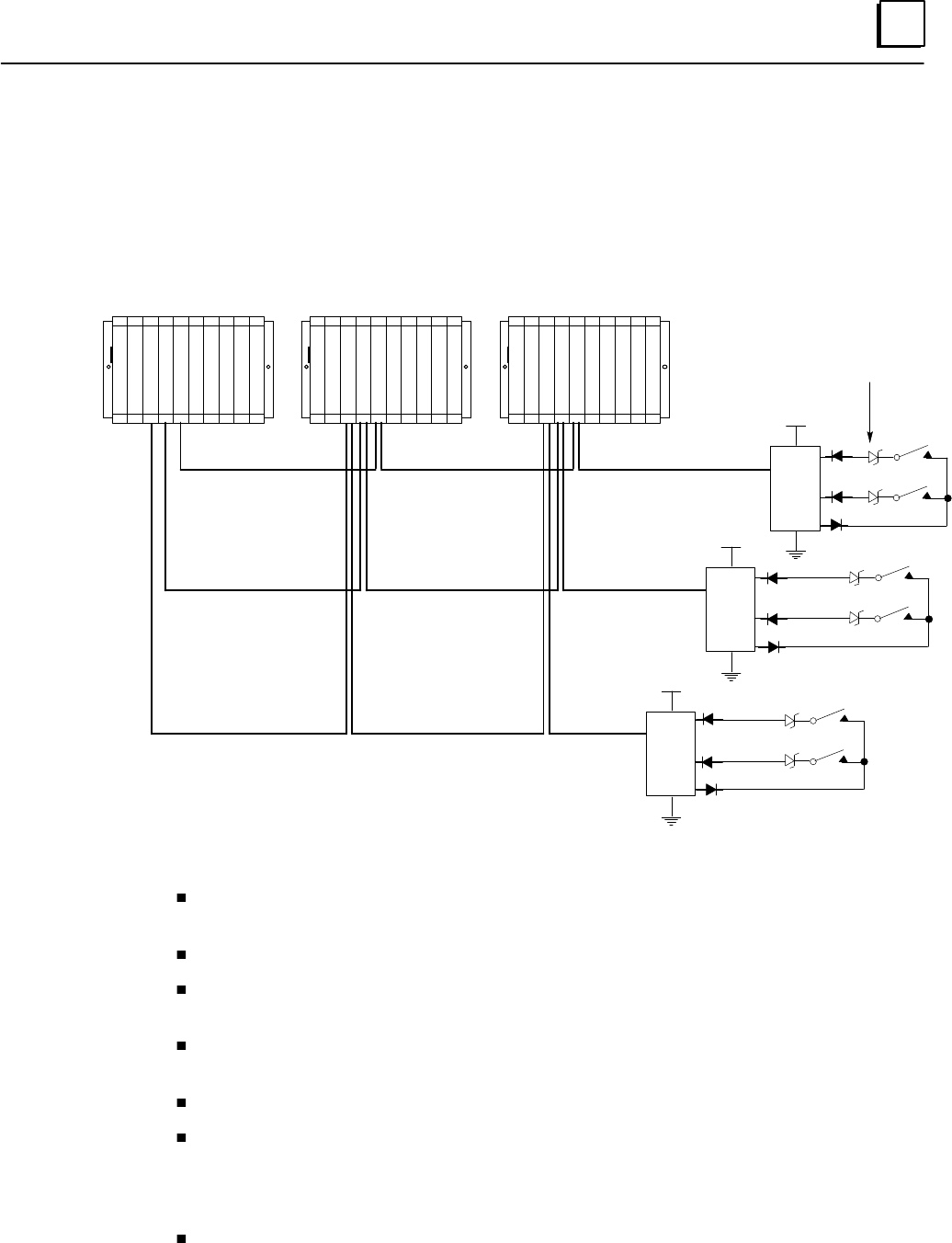
8
8-5GFK-0787B Chapter 8 Installation Information
Input Wiring (continued)
Three Sensors to Three Blocks (Triple Bus)
DC+
I1
I15/32
O16
I1
I15/32
O16
I1
I15/32
O16
Input 1
Input 15 or 32
Input 1
Input 15 or 32
Input 1
Input 15 or 32
DC+
DC+
PLC A PLC B PLC C
6.2V Zener Diodes for
Line Monitoring (optional)
C
P
U
G
B
C
C
G
B
C
A
G
B
C
B
C
P
U
G
B
C
A
G
B
C
B
G
B
C
C
C
P
U
G
B
C
A
G
B
C
B
G
B
C
C
P
SP
SP
S
6.2 volt Zener diodes are used for optional line monitoring on circuits configured as
tristate inputs. This option is only available with 16-circuit DC blocks.
All blocks in an input group must have the same number of circuits (either 16 or 32).
On either 16-circuit or 32-circuit blocks, circuit 16 is used as an output if the block
group is configured for input autotesting.
On any block, circuits that are not configured as part of the GMR input group can be
used as non-redundant inputs or outputs.
All blocks in the input group must be assigned the same serial bus address.
If the block group is configured for input autotesting, it must be wired appropriately.
Each input that is configured (by the GMR Configuration Software) to be autotested
must have its input device wired to receive power from output Q16 of the block
group, as shown above.
Isolation diodes must also be wired as shown above for any input to be autotested.
The suggested diode is 1N5400 or equivalent.
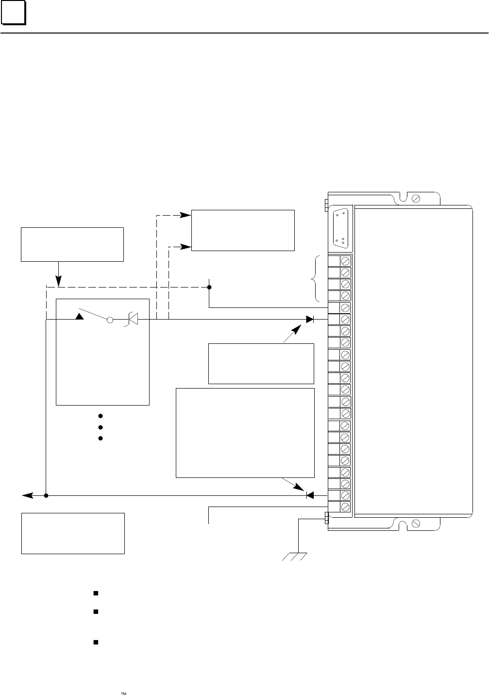
8
8-6 Genius Modular Redundancy Flexible Triple Modular Redundant (TMR) System
User’s Manual – March 1995 GFK-0787B
Input Wiring (continued)
Block Wiring for 16-Circuit Source Block in an Input Group
S1
S2
SHLD IN
SHLD OUT
DC+
1
2
3
4
5
6
7
8
9
10
11
12
13
14
15
16
DC–
Genius Bus
Connections
22V to 56V DC
If single sensor, it must also be
wired to corresponding point on
two other input blocks
Typical for each of up to 15 inputs
DC Source Block IC660BBD020
O VDC
Ground
Point 16 must also be wired to
corresponding point on two
other input blocks if simplex
sensors are used
If group inputs are configured for
autotesting, circuit 16 must be used as an
output
If no autotesting is to be done on this group
of inputs, the input devices must not be
wired to circuit 16. They must be wired to
the power source instead.
Diode required at each powerfeed output
(for Input Autotesting) 1N5400 or equivalent.
Connection if no points on the
block are to be autotested
(must disconnect output 16).
Tristate input requires
series zener diode, voltage
rating 6.2V
*Zener should be wired at
the input device.
*Use of such “super-
vised” inputs is optional.
*
Required at each input (for Input
Autotesting). 1N5400 or
equivalent.
In three-block input group, each block is connected to one bus of three.
If an input is wired for tristate operation, the circuit LED glows dimly when the
input off.
If redundant power supplies are to be used, they should be diode “ORed” power
supplies providing common power to all blocks in a group. Different groups may
use different power sources.
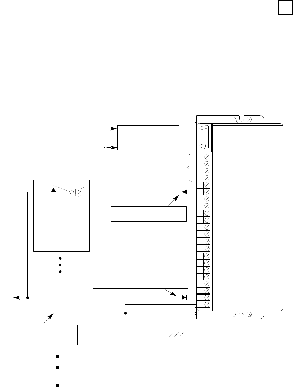
8
8-7GFK-0787B Chapter 8 Installation Information
Input Wiring (continued)
Block Wiring for 16-Circuit Sink Block in an Input Group
S1
S2
SHLD IN
SHLD OUT
DC+
1
2
3
4
5
6
7
8
9
10
11
12
13
14
15
16
DC–
Genius Bus
Connections
22V to 56V DC
Typical for each of up to 15 inputs
DC Sink Block IC660BBD021
O VDC Ground
If group inputs are configured for
autotesting, circuit 16 must be used as an output
If no autotesting is to be done on this group of
inputs, the input devices must not be wired to cir-
cuit 16. They must be wired to the power source
instead.
If group uses single sensors, point 16 must also be
wired to corresponding point on two other input
block.
Diode required at each power feed output (for
input autotesting) 1N5400 or equivalent).
Connection if no points on the
block are to be autotested
(must disconnect output 16).
Tristate input requires par-
allel zener diode, voltage
rating 6.2V
*Zener should be wired at
the input device.
*Use of such “super-
vised” inputs is optional.
*
If single sensor, it must also be
wired to corresponding point on
two other input blocks
Required at each input (for Input
Autotesting). 1N5400 or equivalent.
In three-block input group, each block is connected to one bus of three.
If an input is wired for tristate operation, the circuit LED glows dimly when the
input off.
If redundant power supplies are to be used, they should be diode “ORed” power
supplies providing common power to all blocks in a group. Different groups may
use different power sources.
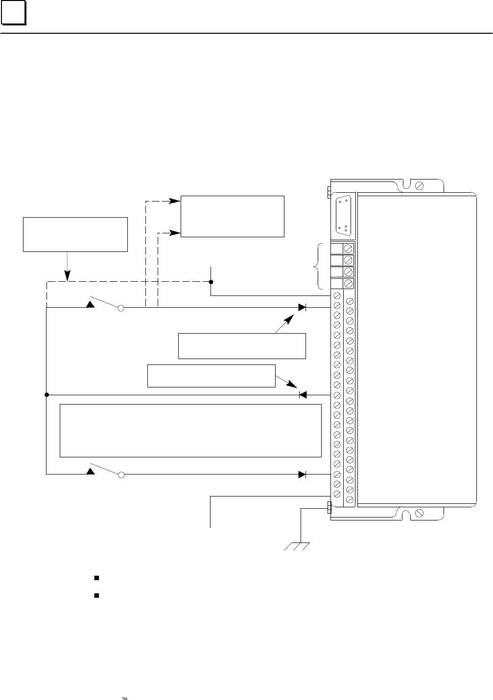
8
8-8 Genius Modular Redundancy Flexible Triple Modular Redundant (TMR) System
User’s Manual – March 1995 GFK-0787B
Input Wiring (continued)
Block Wiring for 32-Circuit Source Block in an Input Group
S1
S2
SHLD IN
SHLD OUT
DC+
DC+
DC+
DC+
DC+
10
12
14
16
18
20
22
24
26
28
30
32
34
36
38
40
42 DC–
DC–
44 DC–
DC–
46 DC–
Genius Bus
Connections
22V to 30V DC
DC Source Block IC660BBD024
O VDC Ground
If group inputs are configured for autotesting, circuit 16 must be used as an output
If no autotesting is to be done on this group of inputs, the input devices must not be
wired to circuit 16. They must be wired to the power source instead.
Connection if no points on the
block are to be autotested
(must disconnect output 16).
If group uses single sensors, point 16 must also be wired to corresponding point
on two other input blocks
Device #1
Device #32
Output 16
If single sensor, it must also be
wired to corresponding point on
two other input blocks
Required at each input (for Input
Autotesting). 1N5400 or equivalent.
Required at each powerfeed output (for
Input Autotesting). 1N5400 or equivalent.
In three-block input group, each block is connected to one bus of three.
If redundant power supplies are to be used, they should be diode “ORed” power
supplies providing common power to all blocks in a group. Different groups may
use different power sources.
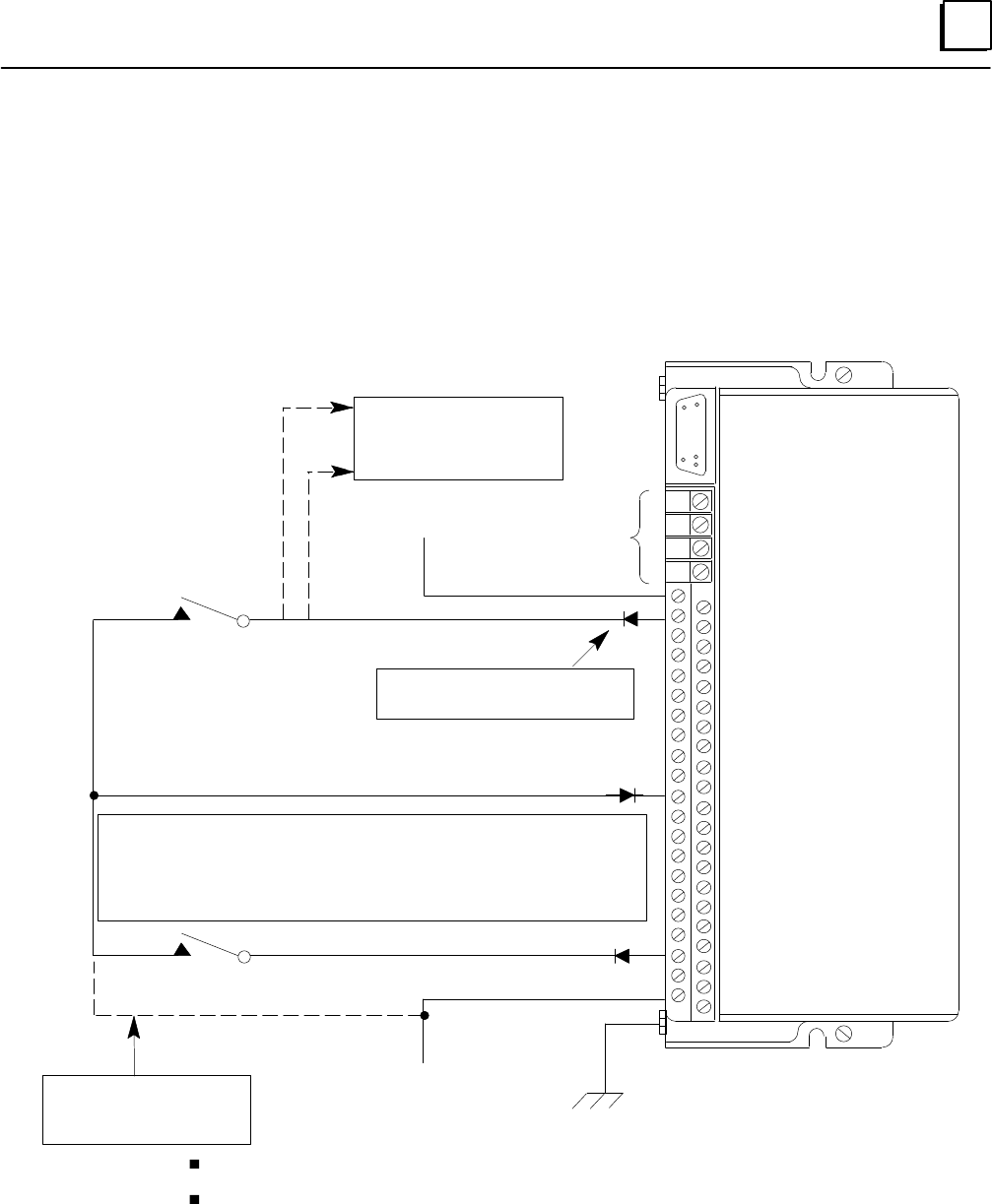
8
8-9GFK-0787B Chapter 8 Installation Information
Input Wiring (continued)
Block Wiring for 32-Circuit Sink Block in an Input Group
S1
S2
SHLD IN
SHLD OUT
+5V
DC+
DC+
DC+
DC+
10
12
14
16
18
20
22
24
26
28
30
32
34
36
38
40
42 DC–
DC–
44 DC–
DC–
46 DC–
Genius Bus
Connections
22V to 30V DC
DC Sink Block IC660BBD025
O VDC Ground
If group inputs are configured for autotesting, circuit 16 must be used as an output
If no autotesting is to be done on this group of inputs, the input devices must not be wired to
circuit 16. They must be wired to the power source instead.
If group uses single sensors, point 16 must also be wired to corresponding point on two
other input blocks
Zener diode required at each powerfeed output (for Input Autotesting). 1N5400 or equivalent.
Connection if no points on the
block are to be autotested
(must disconnect output 16).
Device #1
Device #32
Output 16
If single sensor, it must also be
wired to corresponding point on
two other input blocks
Required at each input (for Input
Autotesting). 1N5400 or equivalent.
In three-block input group, each block is connected to one bus of three.
If redundant power supplies are to be used, they should be diode “ORed” power
supplies providing common power to all blocks in a group. Different groups may
use different power sources.
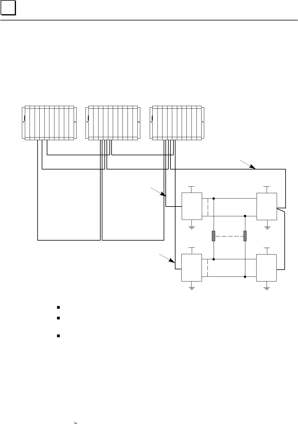
8
8-10 Genius Modular Redundancy Flexible Triple Modular Redundant (TMR) System
User’s Manual – March 1995 GFK-0787B
Output Wiring for a 16-Circuit, 4-Block Group
16-Circuit, 4-Block Output Group
Q1
Block C
(Sink)
DC+
Q1
Block A
(Source)
Q1
Block D
(Sink)
Q16
Q1
Block B
(Source)
Hi
Low
Hi
Low
Output 1 Output 16
DC+
DC+ DC+
Q16
Q16
Q16
Bus A
Bus B
Bus C
C
P
U
G
B
C
C
G
B
C
A
G
B
C
B
C
P
U
G
B
C
A
G
B
C
B
G
B
C
C
C
P
U
G
B
C
A
G
B
C
B
G
B
C
C
P
SP
SP
S
All blocks in an output group must have the same number of circuits (16 or 32).
Block “D” must be connected to the system through bus A or bus B (not bus C). The bus
selected must be the one specified in the GMR configuration.
Unused voted outputs cannot be used as non-voted I/O points.
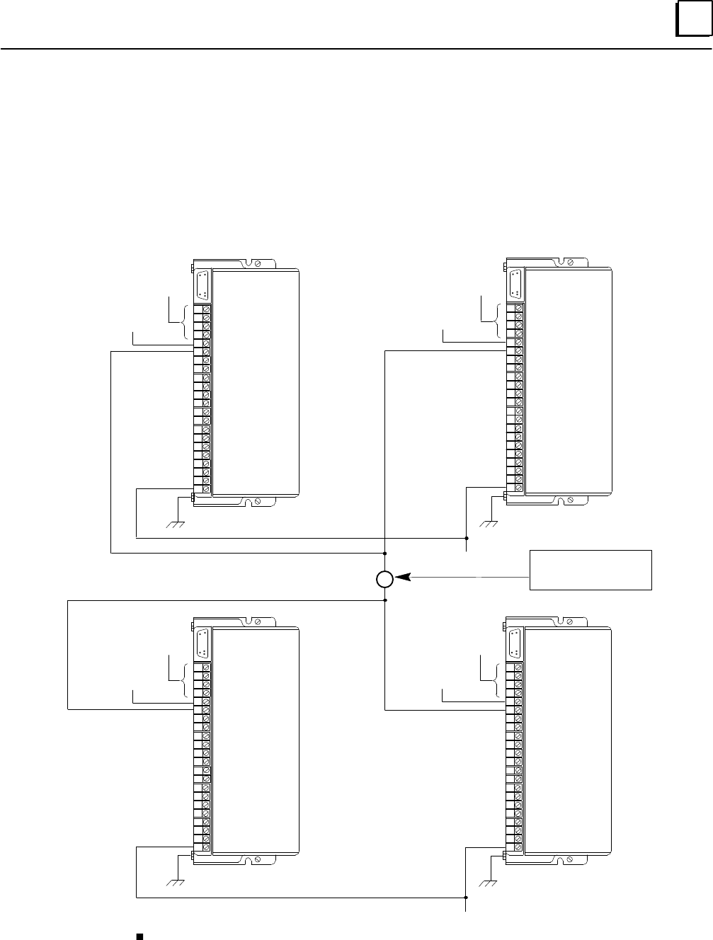
8
8-11GFK-0787B Chapter 8 Installation Information
Output Wiring for a 16-Circuit, 4-Block Group (continued)
Block Wiring for a 16-Circuit 4-Block Output Group
More detailed installation information is provided in the block datasheets. The labels Block
A, Block B, Block C, and Block D refer to the previous system diagram.
S1
S2
SHLD IN
SHLD OUT
OV DC
Ground
S1
S2
SHLD IN
SHLD OUT
DC+
1
2
3
4
5
6
7
8
9
10
11
12
13
14
15
16
DC–
Bus A
Genius Bus
Connections
Ground
Load (–)
Load (100mA minimum)
Typical 16 places
+ DC Power
+ DC Power
DC+
1
2
3
4
5
6
7
8
9
10
11
12
13
14
15
16
DC–
Ground
S1
S2
SHLD IN
SHLD OUT
S1
S2
SHLD IN
SHLD OUT
DC+
1
2
3
4
5
6
7
8
9
10
11
12
13
14
15
16
DC–
Ground
+ DC Power
+ DC Power
DC+
1
2
3
4
5
6
7
8
9
10
11
12
13
14
15
16
DC–
Block C
OV DC
Load (+)
Bus B
Genius Bus
Connections
Bus C
Genius Bus
Connections
Bus A or B
Genius Bus
Connections
IC660BBD021
(Sink)
Block D
IC660BBD021
(Sink)
Block A
IC660BBD020
(Source)
Block B
IC660BBD020
(Source)
If redundant power supplies are to be used, they should be diode “ORed” power
supplies providing common power to all blocks in a group. Different groups may
use different power sources.

8
8-12 Genius Modular Redundancy Flexible Triple Modular Redundant (TMR) System
User’s Manual – March 1995 GFK-0787B
Output Wiring for a 16-Circuit, 4-Block Group (continued)
Output Load Considerations for 16-Circuit 4-Block “H” Pattern
Redundant Output Groups
Minimum load: 100 milliamps
Maximum load: 2.0 Amps
Maximum inrush current: 10 Amps for up to 10 milliseconds
Maximum total load for block group: 15 Amps at 35 degrees C
Output Off Leakage Current: 2.0 milliamps
For Outputs to be Autotested:
Minimum pickup time: Greater than 20 milliseconds
Minimum dropout time: Greater than 7.5 milliseconds
Caution
Check the characteristics of each output device against the list above to
verify that it can be autotested and/or used in the 4-block output
group. Otherwise, critical output loads could be adversely affected.
Output Autotest and Pulse Testing
If output circuits are to be autotested, the loads will be subject to pulse testing, which is
an integral part of the output autotest sequence. Pulse testing verifies the ability of a
block’s outputs to change state with a short pulse that is not intended to affect the actual
load. Pulse testing occurs whether the output is in the On state or in the Off state by
executing one of two tests. These are the pulse ON–OFF–ON test and the pulse
OFF–ON–OFF test. The actual pulse width and the number of times a point is tested
depend greatly on its configuration, state (ON or OFF) and the type of load (or absence
of load) on the point. So, output circuits that are to be autotested must be able to
withstand On and Off pulse times that are discussed below. Each output device’s
characteristics should be checked against the list above to verify that it can be autotested
and/or used in the 4-block output group. The following Pulse Test descriptions refer to
Pulse Test operation of a block configured in the GMR mode only.
OFF–ON–OFF Test
The first ON pulse is for about 1.7mS. During this time, if the No Load diagnostic is
enabled, the current data is checked and recorded. After this time, the test turns the
point Off and the diagnostic, volts, and current data (if No Load is enabled) are checked.
If the correct voltage and/or current data is NOT reported, the time constant is increased
and the process repeats. If the correct voltage and/or current data is reported after any of
the pulses, the test is passed and no further pulsing of the point occurs. The maximum
number of pulses that can occur is 7, with a minimum duration of 1.7mS and a maximum
duration of 20mS. Also, these is a delay of approximately 5 to 15 mS until the same point
is pulsed again. These times depend greatly on the configurations of the other points.
ON–OFF–ON Test
Similar activity occurs for this test. The initial time a point is Off is about 5mS. The only
fault checked for in this case, however, is that the volts feedback agrees with the

8
8-13GFK-0787B Chapter 8 Installation Information
commanded state. If it does not, the point is pulsed Off again for about 7.5mS. A
maximum of two pulses of approximately 5mS and 7.5mS duration can occur. The 7.5mS
pulse occurs only if the volts feedback for the first pulse is incorrect.
Each output device’s characteristics should be checked against the list above to verify
that it can be autotested and/or used in the 4-block output group. Often, in cases where
a desired output device does not by itself meet a requirement, external components can
be added to change its characteristics and allow it to operate in a 4-block output group
and be autotested. Or, a diagnostic feature (such as autotest, No Load, or Overload) can
be disabled to allow it to operate in a 4-block output group. The following are two
examples.
GE Catalog Number CR120BDXXX48 Series A 600–Volt Industrial Relay
XXX represents a 3-digit number identifying the type and number of contacts.
This relay has a NEMA A600 rating: Maximum AC Voltage = 600
Maximum continuous current: = 10A
The 24 VDC coil typically draws 117 milliamps at 24 VDC when the relay is picked up.
This meets the GMR requirement of a minimum of 100 milliamps to be able to use the
No Load diagnostic without using additional external components to increase the load.
However, the 24 VDC coil is a dual winding type which draws a higher current during
the first part of the armature stroke. Its inrush current is approximately 9.8 Amps at
24 VDC, which causes an Overload diagnostic (overload=more than 2.8 Amps) to be
generated by the Genius output circuits. To overcome the high inrush current, the
Overload diagnostic must be set to NO for those outputs that would be wired to this
type or relay. This relay, with no external components, does not exhibit any chatter
during the output autotesting, although a flyback diode is still recommended to reduce
noise on the 24VDC power lines.
GE Catalog Number CR7RBXXEL Spectra 700 IEC Control Relay
XX represents a 2-digit number identifying the type and number of contacts.
This relay has a NEMA A600 rating: Maximum AC Voltage = 600
Maximum continuous current: = 10 A
The 24 VDC coil typically draws 230 milliamps at 24 VDC when the relay is picked up.
This also meets the GMR requirement of a minimum of 100 milliamps to be able to use
the No Load diagnostic without using additional external components to increase the
load. The inrush current for this relay is low enough that the Overload can be left
enabled. However, this relay, with no external components, does exhibit very minor
chatter during the output autotesting, although its contacts do not begin to open. A
flyback diode wired across the coil eliminates all the chatter and is also recommended to
reduce noise on the 24VDC power lines.
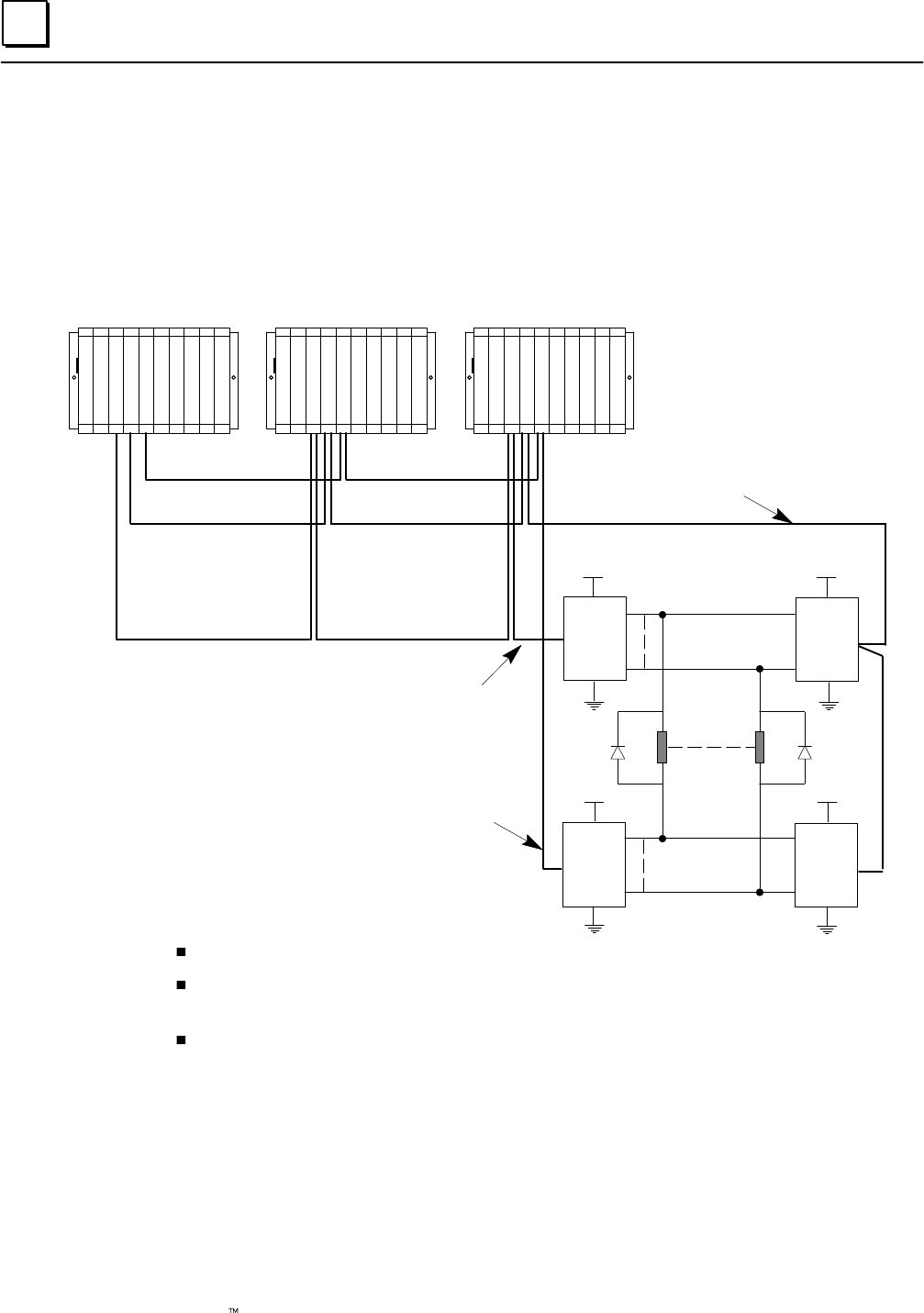
8
8-14 Genius Modular Redundancy Flexible Triple Modular Redundant (TMR) System
User’s Manual – March 1995 GFK-0787B
Output Wiring for a 32-Circuit, 4-Block Group
32-Circuit, 4-Block Output Group
Q1
Block C
(Sink)
DC+
Q1
Block A
(Source)
Q1
Block D
(Sink)
Q32
Q1
Block B
(Source)
Hi
Low
Hi
Low
Output 1
Output 32
DC+
DC+ DC+
Q32
Q32
Q32
Bus A
Bus B
Bus C
C
P
U
G
B
C
C
G
B
C
A
G
B
C
B
C
P
U
G
B
C
A
G
B
C
B
G
B
C
C
C
P
U
G
B
C
A
G
B
C
B
G
B
C
C
P
SP
SP
S
All blocks in an output group must have 32 circuits.
Block “D” must be connected to the system through bus A or bus B (not bus C). The bus
selected must be the one specified in the GMR configuration.
Unused voted outputs cannot be used as non-voted I/O points.
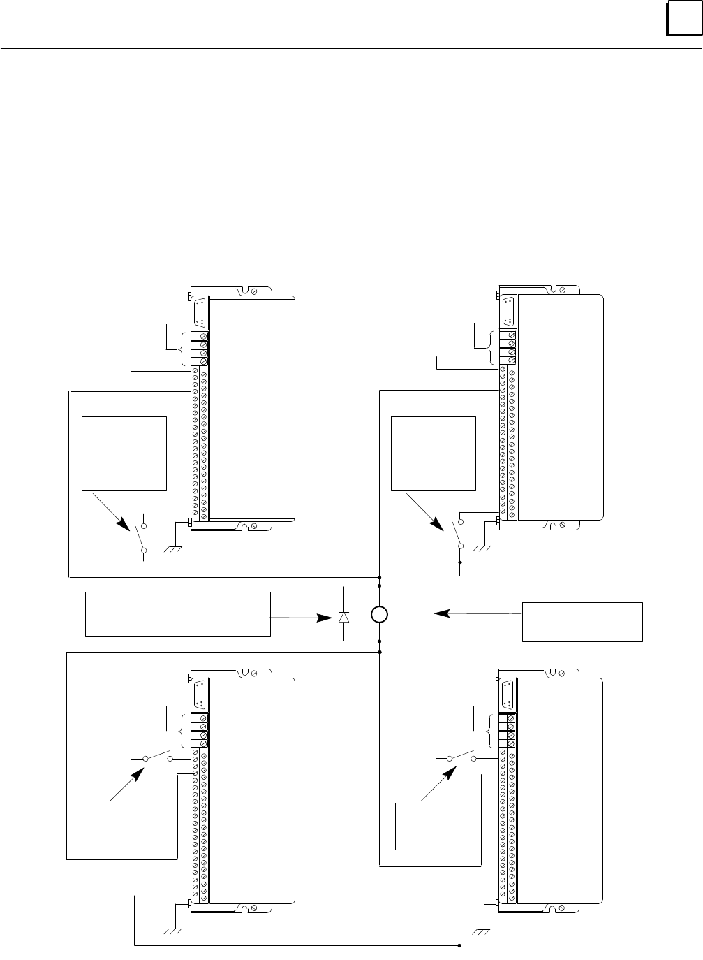
8
8-15GFK-0787B Chapter 8 Installation Information
Output Wiring for a 32-Circuit, 4-Block Group (continued)
Block Wiring for a 32-Circuit 4-Block Output Group
More detailed installation information is provided in the block datasheets. The labels Block
A, Block B, Block C, and Block D refer to the previous system diagram.
S1
S2
SHLD IN
SHLD OUT
OV DC
Ground
S1
S2
SHLD IN
SHLD OUT
Bus A
Genius Bus
Connections
Ground
Load (–) Load Typical 32 places
+ DC Power
+ DC Power
Ground
S1
S2
SHLD IN
SHLD OUT
S1
S2
SHLD IN
SHLD OUT
Ground
+ DC Power
+ DC Power
Block C
OV DC
Load (+)
Bus B
Genius Bus
Connections
Bus C
Genius Bus
Connections
Bus A or B
Genius Bus
Connections
IC660BBD025
(Sink)
Block D
IC660BBD025
(Sink)
Block A
IC660BBD024
(Source)
Block B
IC660BBD024
(Source)
+5V
DC+
10
12
14
16
20
22
24
26
28
30
32
34
36
40
DC–
18
+5V
DC+
10
12
14
16
20
22
24
26
28
30
32
34
36
40
DC–
18
DC+
DC+
10
12
14
16
20
22
24
26
28
30
32
34
36
40
DC–
18
DC+
DC+
10
12
14
16
20
22
24
26
28
30
32
34
36
40
DC–
18
Rectifier “Clamping” Diode should
be wired here for each load (1
Amp, 75 to 100 Volt PIV)
Power discon-
nects for
Source blocks
should be
wired here
Power discon-
nects for
Source blocks
should be
wired here
Power discon-
nects for Sink
blocks should
be wired here
Power discon-
nects for Sink
blocks should
be wired here

8
8-16 Genius Modular Redundancy Flexible Triple Modular Redundant (TMR) System
User’s Manual – March 1995 GFK-0787B
Warning
In certain cases, removing the DC power source from an output block
or blocks which are part of a 32-circuit 4-block output group, causes
leakage currents through the output driver circuits of the powered
down block(s). To ensure that these potential leakage currents do not
adversly affect the output devices being controlled, the following
installation instructions must be followed.
A. All 4 blocks in an output group must be powered from the same common power
source. If redundant power supplies are to be used they should be diode “ored”
power supplies that provide a common power source for the 4 blocks in a group.
Different output groups may use different power sources.
B. Power disconnects for the blocks in a group should be wired such that either a single
disconnect powers down all 4 blocks simultaneously or each individual block is
powered down by its own disconnect. An individual disconnect and/or fuse for each
individual block provides the greatest flexibility in replacing a failed block without
disturbing the controlled output devices.
C. Ideally the disconnect for a source block (IC660BBD024) should be wired in the DC–
supply line and for a sink block (IC660BBD025) in the DC+ supply line.
D. A rectifier diode must be wired in parallel with each output load as shown in the
diagram. This diode should have a minimum 1 Amp forward current rating and 75
volt to 100 volt PIV rating. This diode does not affect the ability of the system to do
output autotesting of each output if configured to do so.
Caution
When a 32-circuit 4-block output group is wired according to the instructions above and
a single block is powered down for maintenance purposes, the following normal
procedures should be followed.
A PLC Force Logon may be required as always when an output block has power
restored to it to cause the output block to start accepting data from the PLC(s). It is
not required if the current output data the PLC(s) is sending matches the output
default states at the block. To execute a PLC Force Logon, turn on the GMR control
bit %M12263 (FORCLOG – Force Block(s) to Log on).
An I/O fault reset should executed after restoring power to a block in an ouput
group. This is done by turning on the GMR control bit %M12258 (IORES – Perform
I/O Fault Table Clear).

8
8-17GFK-0787B Chapter 8 Installation Information
Output Wiring for a 32-Circuit, 4-Block Group (continued)
Output Load Considerations for 32-Circuit 4-Block “H” Pattern Redun-
dant Output Groups
Minimum load: 1.0 milliamp
Maximum load: 0.5 Amp
Maximum inrush current: 4 Amps for up to 10 milliseconds
Maximum total load for block group: 16 Amps at 35 degrees C
Output Off Leakage Current: 20 microamps
For Outputs to be Autotested:
Minimum pickup time: Greater than 1 millisecond
Minimum dropout time: Greater than 1 millisecond
Caution
Check the characteristics of each output device against the list above to
verify that it can be autotested and/or used in the 4-block output
group. Otherwise, critical output loads could be adversely affected.
Output Autotest and Pulse Testing
If output circuits are to be autotested, the loads will be subject to pulse testing, which is
an integral part of the output autotest sequence. Pulse testing verifies the ability of a
block’s outputs to change state with a short pulse that is not intended to affect the actual
load. Pulse testing occurs whether the output is in the On state or in the Off state by
executing one of two tests. These are the pulse ON–OFF–ON test and the pulse
OFF–ON–OFF test. Outputs that are to be autotested must be able to withstand On
and Off pulse times of approximately 1 millisecond.

Asection level 1 1
figure_ap level 1
table_ap level 1
GFT-166 Revision 1.3
April 4, 1995
A-1
GFK-0787B
Appendix ATÜV Certification
TÜV is an acronym for “Technischer Überwachungs–V erein”, which has a rough
translation to English of “Technical Supervisory Group”. TÜV is an independent
German technical inspection agency and test laboratory, widely recognized and
respected for their testing and approval of electronic components and systems for use in
safety critical applications.
GE Fanuc has received TÜV type approval for the GMR system, for use in safety-
relevant applications such as Emergency Shut Down (ESD), according to class 1 through
5 of DIN VDE 0801 standards and requirements. The type approval certificate is 945/EL
273/95. TÜV type approval for the GMR system for use in Fire and Gas applications is
pending. The GMR system may be used in the following configuration for class 4 or 5
applications respectively:
Class 5 – Triplex (2v3) – Fail Safe and Fault Tolerant
Class 5 – Duplex (2v2) – Fail Safe
Class 4 – Duplex (1v2) – Fail Safe and Fault Tolerant
The Genius Modular Redundancy system is a high-reliability, high-availability system. It
is based on the field-proven Series 90-70 PLC and Genius I/O products. These standard
off-the-shelf, general-purpose PLC products are capable of a very wide range of
applications and uses. All of this general-purpose capability carries over to the GMR
system.
All Series 90-70 PLC and Genius I/O products can be used with a GMR system. However,
not all of the available components are TÜV approved for use in the safety relevant
portion of a system. All components can be used, but with restrictions as described in
this appendix. The subset of components that are approved are also listed in this
appendix. In addition, this appendix describes restrictions placed on the design,
configuration, installation and use of a GMR system that will be applied in an
Emergency Shut Down (ESD) application, for which for a TÜV site application approval
will be sought.
A TÜV site application approval consists of a review and check of the system as installed
and commissioned at the final site by a TÜV site engineer. The process includes a review
and check of all installed hardware, software, configuration, procedures and the specific
application program to ensure conformance with the User’s Manuals, the specified
environmental conditions and the following restrictions.

A GFT-166 Revision 1.3
April 4, 1995
A-2 Genius Modular Redundancy Flexible Triple Modular Redundant (TMR) System
User’s Manual – March 1995 GFK-0787B
TÜV Restrictions
For all safety relevant applications the safe state must be the de-energized (0) state.
A Functional test must be performed to check for the correct design and operation of the system as
a whole. This is to include the user’s application program.
No change of the system software (operating system, I/O drivers, diagnostics, etc.) is allowed
without TÜV type approval and recommissioning.
Regulations or procedures for the use of, servicing, and repair of the system with regard to the
application must be available as a part of the operational documents.
All GE Fanuc manufactured components may be used in the non-safety relevant portion of the
system if appropriately de-coupled from the safety-relevant portion of the system. Specifically
approved hardware components for the safety relevant portion are:
Catalog Number Firmware
Revision Level Description
IC697BEM711J n/a Bus Receiver
IC697BEM713F n/a Bus Transmitter
IC697BEM731N 4.8 Genius Bus Controller
IC697CHS790D n/a 9–Slot Rack
IC697CPU788DA 5.50 GMR CPU – 100 Triplex (voted) I/O
IC697CPU789DA 5.50 GMR CPU – 2K Triplex (voted) I/O
IC697MEM735D n/a Expansion memory module 512KB
IC697PWR711CX n/a Power Supply 120/240Vac, 100 Watts
IC660BBA023K 1.4 Genius Thermocouple Input Block, 24/48Vdc
Power, 6 in
IC660BBA021K 1.1 Genius RTD Input Block, 24/48Vdc Power, 6 in
IC660BBA106K 1.0 Genius Current Source Analog Input Block,
115Vac/125Vdc, 6 in
IC660BBA026K 1.0 Genius Current Source Analog Input Block,
24Vdc, 6 in
IC660BBA024K 1.8 Genius Current Source Analog I/O Block,
24/48Vdc, 4 in/2 out
IC660BBD020M 3.6 Genius Source I/O Block, 16 circuit, 24/48Vdc
IC660BBD021M 3.6 Genius Sink I/O Block, 16 circuit, 24/48Vdc
IC660BBD024N 3.7 Genius Source I/O Block, 32 circuit, 12/24Vdc
IC660BBD025N 3.7 Genius Sink I/O Block, 32 circuit, 5/12/24Vdc
Analog input blocks that are used in the safety-relevant portion of the system must be periodically
(e.g. once per year) checked and verified manually by the application and verification of input
signals of at least 10 equally spaced points starting at the low end of the range of the input and
ending at the high end. At least two physical
points of every triplex analog input must be tested in this manner.
Simplex analog sensors can be connected to redundant analog inputs only if those analog inputs
are de-coupled by suitable devices
When blocks IC660BBD024 and IC660BBD025 are used as part of a redundant “H” pattern output
group, an appropriately-sized fuse must be included on each side of the load.
If Power Supply IC697PWR711CX is used with a 230 Volt AC power source, a surge protector/filter
device is required. Any incoming overvoltage transients of up to 4 Kvolts (1.2/50mS) must be limited by
this device to 2.5 Kvolts (1.2/50mS) according to VDE 0160 overvoltage category II. This device must be
installed between the power source and the power supply. 115 Volt AC power source applications do
not require a surge protector/filter device.
Each CPU module must be memory protected and the key removed.

A
GFT-166 Revision 1.3
April 4, 1995
GFK-0787B A-3Appendix A TÜV Certification
The installation procedures in the Series 90-70 Programmable Controller Installation Manual
(GFK-0262D) and this GMR User’s Manual (GFK-0787A) are to be closely observed and complied
with, especially the grounding procedures in chapter 3 of the Series 90–70 Programmable Controller
Installation Manual (GFK-0262D).
All GMR components must be installed in a panel or cabinet which offers protection equal to or
greater than specification IP54. For EMC purposes, the enclosure must provide protection equal
to or greater than an enclosure having the following characteristics: Steel sides with a thickness
of 0.040 inches, no RFI gasketing and all enclosure sides grounded to a common point with
grounding straps equal to or larger than #14 AWG. The panels or cabinets must be closed during
operation of the system. They may be opened only during maintenance or for short term
supervised operation.
The on-line programming option must be set to DISABLED in the configuration.
The simplex shutdown option must be set to be enabled at 60 seconds.
For applications needing to meet DIN VDE 0116 specifications, the maximum Input-to-Output
response time allowed is 1.0 second. To ensure this response time is met under all circumstances,
the maximum watchdog timer setting must be one of the following, whichever is smaller.
((2 * the typical scan time of the application program) – 10 milliseconds)
OR
310 milliseconds (if Genius bus baud rate = 153.6K)
250 milliseconds (if Genius bus baud rate = 76.8K)
130 milliseconds (if Genius bus baud rate = 38.4K)
The Data and System Fault actions must be set as follows: Data Fault – DIAGNOSTIC, System
Fault – FATAL
All redundant I/O groups must be configured to be autotested and the autotest interval must not
exceed a maximum of 480 minutes (8 hours).
The write access length parameters for %I, %AI, %Q, and %AQ must be set to 0.
If the configuration is set to allow write access, the TÜV Maintenance Override document must be
complied with. This document is reprinted in Appendix B of this manual.
Autotesting must be set to ENABLED for all used circuits of each discrete input group.
Vote Adaptation must be set to 3–2–0 for all used circuits of each discrete input group.
The Duplex State must be set to 0 for all used circuits of each discrete input group.
The Default State must be set to 0 for all used circuits of each discrete input group.
Autotesting must be set to ENABLED for all used circuits of each discrete output group.
Normal State must be set to ON for all used circuits of each discrete output group.
Vote Adaptation must be set to 3–2–0 for each analog input group.
The Duplex State and Default State settings for each analog input group are dependent on the
application and must be set as follows:
For High Limit processing – The Duplex State must be set to High
The Default State must be set to Max.
For Low Limit processing – The Duplex State must be set to Low
The Default State must be set to Min.
For each analog input channel, the Threshold Discrepancy Percentage must be set to 0% or to a
percentage value that causes a discrepancy if inputs at the low portion of a range vary by an
amount more than that already allowed by the Limit percentage setting.
The GMR configuration utility must be used to print the GMR-specific configuration data. The
TÜV site engineer will use this printout to verify the configuration data with the requirements of
the overall application.

A GFT-166 Revision 1.3
April 4, 1995
A-4 Genius Modular Redundancy Flexible Triple Modular Redundant (TMR) System
User’s Manual – March 1995 GFK-0787B
Configuration worksheets are available for all I/O block types in the Genius I/O Discrete and Analog
Blocks User’s Manual (GEK-90486-2). Each I/O block used in the safety-relevant portion of the
system must have a worksheet prepared.
Configuration Protect must be Enabled in each block.
The HHM must be configured to use serial bus address 0 (the default).
The following configuration options must be disabled and the HHM keyswitch must be set to
“MON” and the key removed: Change Block ID, Change Block Baud Rate, Change Block
Configuration, Circuit Forcing, Clear Block Faults
All Series 90–70 instructions can be used in the non–safety portion of the user program, but the
following instructions must not be used in the safety relevant portion of the user program:
VME_CFG_RD, VME_CFG_WRT, PIDISA, PIDIND, DO_IO, SUSIO, ALL SFC functions,
COMMREQ, DATA_INIT_COMM, CALL SUB, CALL EXTERNAL.
SVCREQ functions #1, #3, #4, #6, #8, #14 and #19 may not be used.
The NON–safety relevant portion of a program must be “de–coupled” or segregated from the
safety relevant portion by using separate program blocks or subroutines. In addition there must
be no overlap of I/O reference addresses in the two separate portions of the program. Control
algorithms must NOT be in any way integrated with the safety relevant portion of the program.
No forces or overrides can be present in the system. This is checked by verifying system variables
%S0012 (FRC_PRE) and %S0011 (OVR_PRE) are equal to 0. The application program must include
code that issues a warning to the operator, via a redundant PLC output, if %S0012 or %S0011 are
in the on state in any of the three PLCs.
The application program must include code that issues a warning to the operator to indicate that a
fault (any fault) exists in the system, via a redundant PLC output, if system variable %SC0009
(ANY_FLT) is in the on state in any of the three PLCs.
The GMR control bits, %M12258 (IORES), %M12259 (PLCRES) and %M12264 (PLCRESG), must not
be driven by the application automatically. They must be driven only under control of an operator
(Operator interface or hard wired push– button inputs).
A status report must be produced by setting the GMR REPORT bit (%M12262). The resultant
information must be checked verified against the configuration printout.
Two backup copies of the system configuration and application program must be made for
documentation and backup purposes. These backups must be verified to be identical to what
resides in the PLCs by use of the Logicmaster 90–70 software.
Inputs from other systems to any part of the safety relevant portion of the application program
must be made via the safety relevant inputs of the GMR system. If a software interface, it must be
made through that group of input addresses reserved for the safety relevant portion of the
application. In addition, it must be verified that any non safety inputs cannot override a demand
made to an output by the safety relevant portion of the program or prevent any field input to the
safety relevant portion of the program.
Manual trips and overrides must be executed exclusively during maintenance of the system. The
specific requirements are described in the document “Maintenance Override, Version 2.2, Sept. 8,
1994, which is reprinted in GFK–0787B.
The Force Logon control bit must be set via a hard wired input device, as described in chapter 7 of
GFK–0787B. PLC force logon is to be considered a maintenance override and shall be subject to
requirements described in the document “Maintenance Override, Version 2.2, Sept. 8, 1994,
which is reprinted in GFK–0787B.
The Cancel I/O Shut Down control bit (%M12265 – SD_CAN) must left in the off (0) state and
must not used in any portion of the application program.
When the final commissioned application program is stored to the PLCs, all program data
including reference tables must be stored. The procedures in document GFK-0787B starting at
page 7-31 should be observed.
Bsection level 1 1
figure_ap level 1
table_ap level 1
B-1
GFK-0787B
Appendix BMaintenance Override
The information in this appendix is reprinted by permission of TUV.
Abstract
Suggestions are made about the use of maintenance override of safety relevant sensors
and actuators. Ways are shown to overcome the safety problems and the inconvenience
of hardwired solutions. A checklist is given.
Maintenance Override
There are basically two methods used now to check safety relevant peripherals
connected to PLCs:
Special switches connected to inputs of the PLC. These inputs are used to deactivate
actuators and sensors under maintenance. The maintenance condition is handled as
part of the application program of the PLC.
During maintenance sensors and actuators are electrically switched off of the PLC
and checked manually by special measures.
In some cases, e.g. where space is limited, there is the wish to integrate the maintenance
console to the operator display, or to have the maintenance covered by other strategies.
This introduces the third alternative for maintenance override:
Maintenance overrides caused by serial communication to the PLC.
This possibility has to be handled with care and is introduced in this paper.
Maintenance Override Procedures
Connecting to PLC via serial lines is possible mainly in two ways:
A. The serial link is done via the MODBUS RTU protocol or other approved serial
protocols. The maintenance override may not be performed by the engineering
workstation or programming environment.
B. The engineering workstation or programming environment is allowed to be
connected to the PLC to perform maintenance override. That requires additional
safety measures inside the associated PLC to prevent a program change during
maintenance intervals. These measures shall be approved, e.g. by TUV.

B
B-2 Genius Modular Redundancy Flexible Triple Modular Redundant (TMR) System
User’s Manual – March 1995 GFK-0787B
The following table shows common requirements. The differences between solution A
and B are shown by typeface italic.
Requirements for maintenance override handling Responsibility
Already during the software configuration of the PLC
system it is determined in a table or in the application
program, whether the signal is allowed to be overridden.
Project engineer and commissioner
responsible for correct configuration.
The configuration may also specify by a table, whether
simultaneous overriding in independent parts of the ap-
plication is acceptable.
A. Project engineer
B. Project engineer, Type approval
Maintenance overrides are enabled for the whole PLC or
a subsystem (process unit) by the DCS or a hard-wired
switch (e.g. key switch).
A. Operator or Maintenance engineer.
B. Type approval
A. The override is activated via DCS.
B. The maintenance engineer activates the override via the
programming environment.
As an organizational measure, the operator should con-
firm the override condition.
A. Operator, Maintenance engineer
B. Type approval, Maintenance
engineer
Direct overrides on inputs and outputs are not allowed.
Overrides have to be checked and to be implemented in
relation to the application. Multiple overrides in a PLC are
allowed as long as only one override is used in a given
safety related group. The alarm shall not be overridden.
A. Project engineer
B. Project engineer, Type approval
The PLC alerts the operator, e.g. via the DCS, indicating
the override condition. The operator will be warned until
the override is removed.
Project engineer, Commissioner
A. The override is removed via DCS.
B. The maintenance engineer removes the override via the
programming environment.
A. Operator, Maintenance engineer
B. Maintenance engineer
A. There should be a second way to remove the maintenance
overrode condition.
B. If urgent, the maintenance engineer can remove the
override by the hard-wired switch.
A. Project engineer
B. Maintenance engineer, Type
approval
During the time of override proper operational measures
have to be implemented. The time span for overriding
shall be limited to one shift (typically not longer than 8
hours), or hard-wired common maintenance override
switch (MOS) lamps shall be provided on the operator
console (one per PLC or per process unit).
Project engineer, Commissioner, DCS
program, PLC program
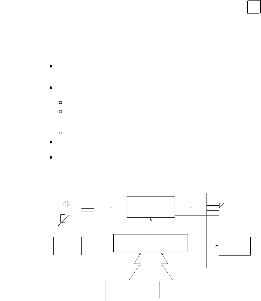
B
GFK-0787B B-3Appendix B Maintenance Override
Recommendations
The following recommendations are given to improve the primary safety as described
by the list:
A program in the DCS that checks regularly that no discrepancies exist between the
override command signals from the DCS and the override activated signals received
by the DCS from the PLC.
The use of the maintenance override function should be documented on the DCS
and on the programming environment if connected. The printout should include:
time stamp of begin and end.
ID of the person who is activating the maintenance override—maintenance
engineer or operator (if the information cannot be printed, it should be entered
in the work-permit).
tag name of the signal being overridden.
The communication packages different from a type-approved MODBUS should
include CRC, address check and check of the communication time frame.
Lost communications should lead to a warning to the operator and maintenance
engineer. After loss of communication a time delayed removal of the override should
occur after a warning to the operator.
hard-wired
switch
Distributed
Control System
(DCS)
Engineering
Workstation
Maintenance Override Handling
(Application Program) Warning to
the Operator
Safeguarding
Application Program
Sensors
PLC
serial line (e.g. Modbus) serial line
Actuators
Version History
This version 2.2 supersedes the version 2.1 from 24. Jun 1994

Index
Index-1
GFK-0787B
A
Alarm and Fault contacts, 5-25 , 5-28 , 7-21
Analog blocks, 1-8
Analog I/O, addressing, 7-7
Analog inputs, 4-12
configuring memory for, 6-18
configuring references for, 6-33
discrepancy, 5-13 , 6-36
maximum, minimum, 6-35
Application program
inhibiting, 4-4 , 7-11
storing to PLC, 7-31
updating on SNP network, 1-3
Asynchronous autotest, 4-18 , 6-29
Autotest, 1-7 , 4-18 , 6-29
configuring for inputs, 6-29
configuring for outputs, 6-37
discrete inputs, 2-6
fault, 5-25 , 5-26
sequence, 5-4
B
Block I/O type, configuring, 6-52
Bus connections, 8-2
Bus Controllers
configuration for, 6-25 , 6-45 , 6-49
extra, for communications, 1-4
model numbers, 1-2
number, 1-4 , 6-4
C
Cancel I/O Shutdown control bit, 4-18
Channel Shorted fault, 5-28
Circuit I/O type, configuring for I/O block,
6-52
Command flags, 7-13
Communications between PLCs, 4-22
Configuration, 6-1
adding GMR configuration to applica-
tion program, 7-29
basic steps, 6-2 , 6-46
checksum, 4-2 , 6-4
copy folder, 6-2
CPU, 6-15
Genius blocks, 6-50
GMR software, 6-4
GMR, create or select, 6-10
Logicmaster 90, 6-45
overview, 1-10
storing to PLC, 7-31
Control bits, Cancel I/O Shutdown, 4-19
CPU, model numbers, 1-2
CPU performance data, sweep impact of
Genius I/O and GBCs, 4-6
CPU sweep, 4-5
Current-loop inputs, 2-9
D
D Block, 6-39
Data initialization, 4-4
Datagram communications, 1-4
Default state, 6-35
Diagnostics, 5-1
autotest, 5-2
Autotest fault, 5-25
Channel Shorted fault, 5-28
Discrepancy fault, 5-25 , 5-28
discrepancy reporting, 5-2
Failed Switch fault, 5-2 , 5-26
Internal Channel fault, 5-28
Line fault, 5-2 , 5-25
No Load fault, 5-2
Open Wire fault, 5-28
Overload fault, 5-2
Overrange fault, 5-28
Overtemperature fault, 5-2
Short Circuit fault, 5-2 , 5-27
State fault, 5-2
types of input diagnostics, 5-2
types of output diagnostics, 5-2
Underrange fault, 5-28
Directory, configuration, change, 6-12
Discrepancy fault, 5-28
Discrepancy reporting, 5-11 , 5-25
analog inputs, 2-10 , 5-13
discrete inputs, 2-5
discrete outputs, 5-12
Do I/O and Suspend I/O, 7-3
Duplex default, 3-3 , 6-54

Index
Index-2 GFK-0787B
Duplex state, 6-34
F
Failed Switch detection, 3-9 , 5-2
Failed Switch fault, 5-26
Fault actions, configuring, 6-22 , 6-23
Fault and Alarm contacts, 5-25 , 5-28 , 7-21
Fault Reporting, 5-3
Fault reporting, 2-2
configuring for I/O blocks, 6-52
in GMR mode, 3-9
Fault Reportting, 6-50
Fault Tables, 5-15
clearing, 5-15 , 7-14
messages for GMR, 5-18
monitoring, 7-10
Fault–locating references, 7-21
Forces and Overrides, 7-10
G
%G memory mapping, 7-27
G_M_R10 Program Block, 6-43
Genius blocks
configuration, 6-50
enhanced for GMR, 1-2
number per input group, 2-3
using in GMR application, 1-8
Genius bus, PLC connections, 6-4
Global Data, 4-22
amount of, 1-3
in %G memory, 7-27
length, 7-27
programming, 7-27
redundancy, 7-9
stored in %R memory, 7-9
GMR configuration
adding to application program, 7-2 ,
7-29
creating the G_M_R10 output file, 6-43
information needed for, 6-5
menus, 6-14
open saved file, 6-10
printing, 6-44
saving, 6-11
software, 6-4
text description, 6-13
GMR mode, 2-6 , 3-9
GMR software
adding to application program, 7-28
files on diskette, 1-2
operation of, 4-5
overview, 1-10
revision level, 1-10 , 6-4
H
Hand-held Monitor, 6-50
version required, 1-2
Hot Standby mode, 2-6 , 3-9 , 3-10 , 6-53 ,
7-15
I
I/O Point faults, 7-20
I/O Shutdown, 4-18 , 7-20
Initialization data, 4-4
Input block groups, 2-2 , 2-3
Input subsystems, 2-1 , 2-2
Inputs
analog, 2-9 , 4-12
analog input voting, 4-12
analog, configuring, 6-33
autotest, 2-6 , 5-5
broadcast, 2-2
configuring autotest, 6-29
configuring references, 6-28
discrepancy reporting, 5-11
discrete, 2-5
discrete input voting, 4-7 , 4-10
fault table messages, 5-16
GMR configuration for, 6-27 , 6-40 , 6-42
Input Table addressing, 7-5
line monitoring, 2-7 , 5-14
manual controls, 2-8
non-voted, 2-4
number of groups, 2-3 , 6-18
number of sensors, 1-6
processing by PLC, 1-6 , 4-7
reserved, 5-24
sensors, 2-3
thresholds, 5-14
voting adaptation, 6-31 , 6-34
wiring, 8-3 , 8-5 , 8-6 , 8-7 , 8-8 , 8-9

Index
Index-3
GFK-0787B
Inputs and outputs, number available, 1-9
Installation information, 8-1
Internal Channel fault, 5-28
L
LED, Block OK, 3-9
Limit discrepancy, 5-12 , 6-36
Line fault, 5-2 , 5-25
Line monitoring, 2-7
Load sharing by output blocks, 3-6 , 5-16
Logicmaster software, version required,
1-2
Logon control, 7-17
Loss of Block fault, 4-18 , 6-30
M
%M command flags, 7-13
%M initialization data, 7-9 , 7-16
%M status definitions, 7-11
Manual inhibit, 2-8
Manual override, 3-8 , 5-23
Manual trip, 2-8 , 3-8 , 5-23
N
No Load fault, 3-9 , 5-2 , 5-16 , 5-26
Non-voted analog inputs, 2-10
Non-voted discrete I/O, 1-9 , 2-4
O
Open Wire fault, 5-28
Output blocks, 3-2
configuring serial bus address, 6-37
Output controls, 5-23
Output groups, 3-2 , 3-6
Output subsystems, 3-1 , 3-2
Outputs
autotesting, 5-7
configuring autotest, 6-37
disabled at startup, 4-2
discrepancy reporting, 5-12
discrepancy status, 7-11
discrete, in PLC, 4-17
discrete, voting, 3-3
enabled, 7-12
enabling at startup, 7-16
fault reporting, 3-5
GMR configuration, 6-37
load sharing, 3-6 , 5-16
logical references, 5-26
manual trip and override, 3-8
Output Table addressing, 7-5
physical references, 5-26
processing by PLC, 1-7 , 4-17
pulse test during autotest, 5-10
reference addresses, 6-37
voting by blocks, 1-7
wiring, 8-10 , 8-11 , 8-12 , 8-14 , 8-15 ,
8-17
Outputs and inputs, number available, 1-9
Overhead sweep impact time, sweep im-
pact of Genius I/O and GBCs, 4-6
Overload fault, 5-2 , 5-26
Overrange fault, 5-28
Overtemperature fault, 5-2 , 5-26
P
PLC Online status, 7-11
PLC operation, 1-3 , 1-7 , 4-1 , 4-5
Power supplies for blocks, 8-3 , 8-6 , 8-7 ,
8-8 , 8-9
Powerfeed output, 4-18 , 6-30
Program Download utility, 7-35
Programming, overview, 1-10 , 7-2
Pulse test operation, 5-10
Pulse testing, configuring for I/O blocks,
6-52
R
%R memory, 7-9
Redundancy mode, 3-9 , 6-53
Reference address, configuring for I/O
block, 6-51

Index
Index-4 GFK-0787B
References for inputs, 6-28
References, reserved, 7-4
Register memory
assignments for GMR, 7-9
configuring amount, 6-18
reserved, 7-4
RTD blocks, 1-8
S
%S status references, 7-10
Serial bus address, configuring, 6-28 , 6-33
, 6-37 , 6-45 , 6-51
Short Circuit fault, 5-2 , 5-26
SNP communications, 1-3
Startup, 4-2
Startup status, 7-16
Startup, programming for, 7-15
State fault, 5-26
Status bits, Shutdown Timer Activated,
4-19
Status flags, resetting, 7-12
Status information, 7-11
Status references, system, 7-10
Synchronization data, 4-2 , 4-4 , 6-19 , 6-20,
7-9 , 7-11 , 7-15
Synchronous Autotest, 4-18 , 6-29
T
Test interval, 6-16
Thermocouple blocks, 1-8
Threshold discrepancy, 5-12 , 6-36
Thresholds, voltage, 2-6 , 3-9
Tristate inputs, 2-6 , 2-7 , 5-14 , 6-52 , 8-3 ,
8-5 , 8-6 , 8-7
U
Underrange fault, 5-28
W
Wiring Error fault, 5-28
Wiring information, 8-3 , 8-5 , 8-6 , 8-7 ,
8-8, 8-9 , 8-10 , 8-11 , 8-12 , 8-14 , 8-15 ,
8-17
Z
Zener diodes, 2-3 , 2-7 , 5-14 , 6-52 , 8-3 ,
8-5 , 8-6 , 8-7
