Ge Appliances General Electric Outboard Motor Lm10 Users Manual Protection System
lm10 7b49f7c8-cab8-43a4-bfe5-e7aab43ec9f7 GE Outboard Motor LM10 User Guide |
2015-01-23
: Ge-Appliances Ge-Appliances-General-Electric-Outboard-Motor-Lm10-Users-Manual-256151 ge-appliances-general-electric-outboard-motor-lm10-users-manual-256151 ge-appliances pdf
Open the PDF directly: View PDF ![]() .
.
Page Count: 106 [warning: Documents this large are best viewed by clicking the View PDF Link!]
- Introduction
- Installation
- Interface
- Functionality
- Communications
- Miscellaneous
- Index
LM10 MOTOR PROTECTION SYSTEM – INSTRUCTION MANUAL 1–1
GE Consumer & Industrial
Multilin
GE Multilin's Quality
Management System is
registered to ISO9001:2000
QMI # 005094
UL # A3775
I
ISO9001:2000
G
E
M
U
L
T
I
L
I
N
R
E
G
I
S
T
E
R
E
D
LM10 revision: 1.7x
GE publication code: GEK-106642E
GE Multilin part number: 1601-0165-A6
Copyright © 2008 GE Multilin
GE Multilin
215 Anderson Avenue, Markham, Ontario
Canada L6E 1B3
Tel: (905) 294-6222 Fax: (905) 201-2098
Internet: http://www.GEmultilin.com
*1601-0165-A6*
LM10 Motor Protection System
Instruction Manual
© 2008 GE Multilin Incorporated. All rights reserved.
GE Multilin LM10 Motor Protection System instruction manual for revision 1.70.
LM10 Motor Protection System, is a registered trademark of GE Multilin Inc.
The contents of this manual are the property of GE Multilin Inc. This documentation is
furnished on license and may not be reproduced in whole or in part without the permission
of GE Multilin. The content of this manual is for informational use only and is subject to
change without notice.
Part numbers contained in this manual are subject to change without notice, and should
therefore be verified by GE Multilin before ordering.
Part number: 1601-0165-A6 (March 2008)

1TABLE OF CONTENTS
LM10 MOTOR PROTECTION SYSTEM – INSTRUCTION MANUAL 1–I
Table of Contents
1: INTRODUCTION DESCRIPTION .....................................................................................................................1-1
THE LM10 RELAY ............................................................................................................... 1-1
OVERVIEW ...........................................................................................................................1-2
FEATURES ............................................................................................................................. 1-2
CURRENT AND VOLTAGE INPUTS ...................................................................................... 1-2
RELAY OUTPUTS .................................................................................................................. 1-2
POWER SUPPLY ................................................................................................................... 1-3
BLOCK DIAGRAM ................................................................................................................. 1-3
FEATURES ............................................................................................................................1-4
PROGRAMMING AND DISPLAY UNIT ................................................................................. 1-4
LED INDICATORS ................................................................................................................. 1-4
SWITCHES ............................................................................................................................. 1-4
ORDERING ..........................................................................................................................1-6
ORDER CODES ..................................................................................................................... 1-6
SPECIFICATIONS ................................................................................................................1-7
PROTECTION ELEMENTS ...................................................................................................... 1-7
METERING ............................................................................................................................. 1-7
CONTROL FUNCTIONS ........................................................................................................ 1-8
INPUTS .................................................................................................................................. 1-8
CT DIMENSIONS .................................................................................................................. 1-10
OUTPUTS ...............................................................................................................................1-10
COMMUNICATIONS .............................................................................................................. 1-10
ENVIRONMENTAL ................................................................................................................. 1-11
APPROVALS/CERTIFICATION ............................................................................................... 1-11
2: INSTALLATION WIRING ................................................................................................................................2-13
DEVICENET ........................................................................................................................... 2-13
RS232 PORT ....................................................................................................................... 2-13
CONTROL TERMINALS ......................................................................................................... 2-14
SENSOR PACK INPUT .......................................................................................................... 2-15
WIRING DIAGRAM ............................................................................................................... 2-15
MOUNTING .........................................................................................................................2-17
LM10 MOUNTING .............................................................................................................. 2-17
PDU DOOR MOUNT ........................................................................................................... 2-18
3: INTERFACE PDU OPERATIONS .............................................................................................................3-19
LIQUID CRYSTAL DISPLAY ................................................................................................... 3-19
LEDS ..................................................................................................................................... 3-19
KEYPAD ................................................................................................................................. 3-19
PDU SCREENS AND MENUS ............................................................................................3-21
MAIN STARTUP SCREEN ..................................................................................................... 3-21
HISTORY RECORD AND STATUS SCREENS ........................................................................ 3-21
CONFIGURATION MENU ..................................................................................................... 3-21
ENERVISTA LM10 SOFTWARE ........................................................................................3-23
DESCRIPTION ........................................................................................................................ 3-23
FUNCTIONAL DETAILS ......................................................................................................... 3-23

1–II LM10 MOTOR PROTECTION SYSTEM – INSTRUCTION MANUAL
TABLE OF CONTENTS
4: FUNCTIONALITY OVERCURRENT FAULT CONDITIONS ............................................................................4-25
DESCRIPTIONS ...................................................................................................................... 4-25
TRIP CURVES EXAMPLE .......................................................................................................4-27
CONFIGURATION SETTINGS ...........................................................................................4-29
OVERVIEW ............................................................................................................................ 4-29
MAIN MENU .........................................................................................................................4-30
LANGUAGE ............................................................................................................................4-31
CTS AND CPTS .................................................................................................................... 4-31
STARTER TYPE ......................................................................................................................4-32
RUN 1 AND RUN 2 SETUP ................................................................................................. 4-32
TIME DELAYS ........................................................................................................................ 4-34
OTHER SETTINGS .................................................................................................................4-34
AUXILIARY RELAY FAULTS .................................................................................................. 4-36
PASSCODE AND LOGIN ....................................................................................................... 4-37
RUN OPERATIONS ................................................................................................................4-38
FACTORY DEFAULT .............................................................................................................. 4-38
STATUS VALUES .................................................................................................................4-39
MAIN MENU .........................................................................................................................4-39
HISTORY VALUES ...............................................................................................................4-41
LAST TRIP DATA ................................................................................................................... 4-41
MOTOR START/STOP LOGIC ...........................................................................................4-42
5: COMMUNICATIONS DEVICENET OPERATIONS ................................................................................................5-45
DESCRIPTION ........................................................................................................................ 5-45
POLL DATA ...........................................................................................................................5-45
IDENTITY OBJECT ..................................................................................................................5-47
MESSAGE ROUTER ...............................................................................................................5-47
DEVICENET OBJECT ............................................................................................................ 5-47
ASSEMBLY OBJECT .............................................................................................................. 5-48
CONNECTION OBJECT ......................................................................................................... 5-52
ACK HANDLER OBJECT ..................................................................................................... 5-54
OVERLOAD OBJECT .............................................................................................................5-54
EXTENSION OBJECT ............................................................................................................. 5-55
DATA FORMATS ................................................................................................................... 5-57
SPECIAL APPLICATION .........................................................................................................5-61
SERIAL PORT .......................................................................................................................5-63
DESCRIPTION ........................................................................................................................ 5-63
6: MISCELLANEOUS REVISION HISTORY ...........................................................................................................6-65
RELEASE DATES ................................................................................................................... 6-65
CHANGES TO THE MANUAL ................................................................................................ 6-65
WARRANTY .........................................................................................................................6-67
GE MULTILIN WARRANTY .................................................................................................. 6-67
APPENDIX DEVICENET OVERVIEW ....................................................................................................A-1
DESCRIPTION ........................................................................................................................ A-1
CONTROLLER AREA NETWORK (CAN) .............................................................................. A-2
DEVICENET OPERATIONS ...................................................................................................A-2
EXPLICIT MESSAGING AND INPUT/OUTPUT (I/O) MESSAGING .....................................A-3
PRE-DEFINED MASTER/SLAVE CONNECTION SET ...........................................................A-3

1TABLE OF CONTENTS
LM10 MOTOR PROTECTION SYSTEM – INSTRUCTION MANUAL 1–III
DEVICENET FEATURES ........................................................................................................ A-3
MAXIMUM CABLE LENGTHS FOR DEVICENET ................................................................. A-3
DEVICENET SPECIFICATION HIGHLIGHTS ......................................................................... A-4
LM10 AND GE FANUC 90-30 WITH DEVICENET™ .....................................................A-6
OVERVIEW ............................................................................................................................ A-6
GE FANUC 90-30 PLC HARDWARE ............................................................................... A-6
NETWORK CONFIGURATION ............................................................................................... A-6
CONFIGURATION PROCEDURE ........................................................................................... A-6
POLLING INPUT/OUTPUT CONNECTION ........................................................................... A-7
COS (CHANGE OF STATE) INPUT/OUTPUT CONNECTION ............................................. A-10
CYCLIC INPUT/OUTPUT CONNECTION .............................................................................. A-10
EXPLICIT MESSAGING .......................................................................................................... A-11
LM10 AND ALLEN-BRADLEY SLC500 VIA DEVICENET™ ..........................................A-17
DESCRIPTION ........................................................................................................................ A-17
SYSTEM SETUP ..................................................................................................................... A-17
INITIAL STEPS ....................................................................................................................... A-17
SETTING UP THE DEVICENET NETWORK ......................................................................... A-17
CHANGING THE MODE OF OPERATION ............................................................................ A-18
CONFIGURING THE SLAVE DEVICE .................................................................................... A-19
CONTROL AND MONITORING OF THE LM10 .................................................................. A-20
EXPLICIT MESSAGING WITH THE LM10 RELAY ............................................................... A-21
DATA TABLE LAYOUT .......................................................................................................... A-22
LADDER LOGIC ..................................................................................................................... A-23
INDEX
1–IV LM10 MOTOR PROTECTION SYSTEM – INSTRUCTION MANUAL
TABLE OF CONTENTS
LM10 MOTOR PROTECTION SYSTEM – INSTRUCTION MANUAL 1–1
LM10 Motor Protection System
Chapter 1: Introduction
GE Consumer & Industrial
Multilin
Introduction
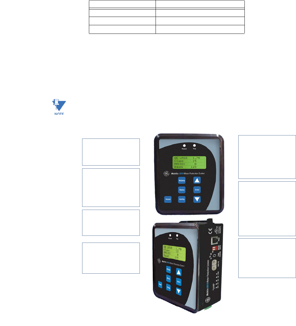
1.1 Description
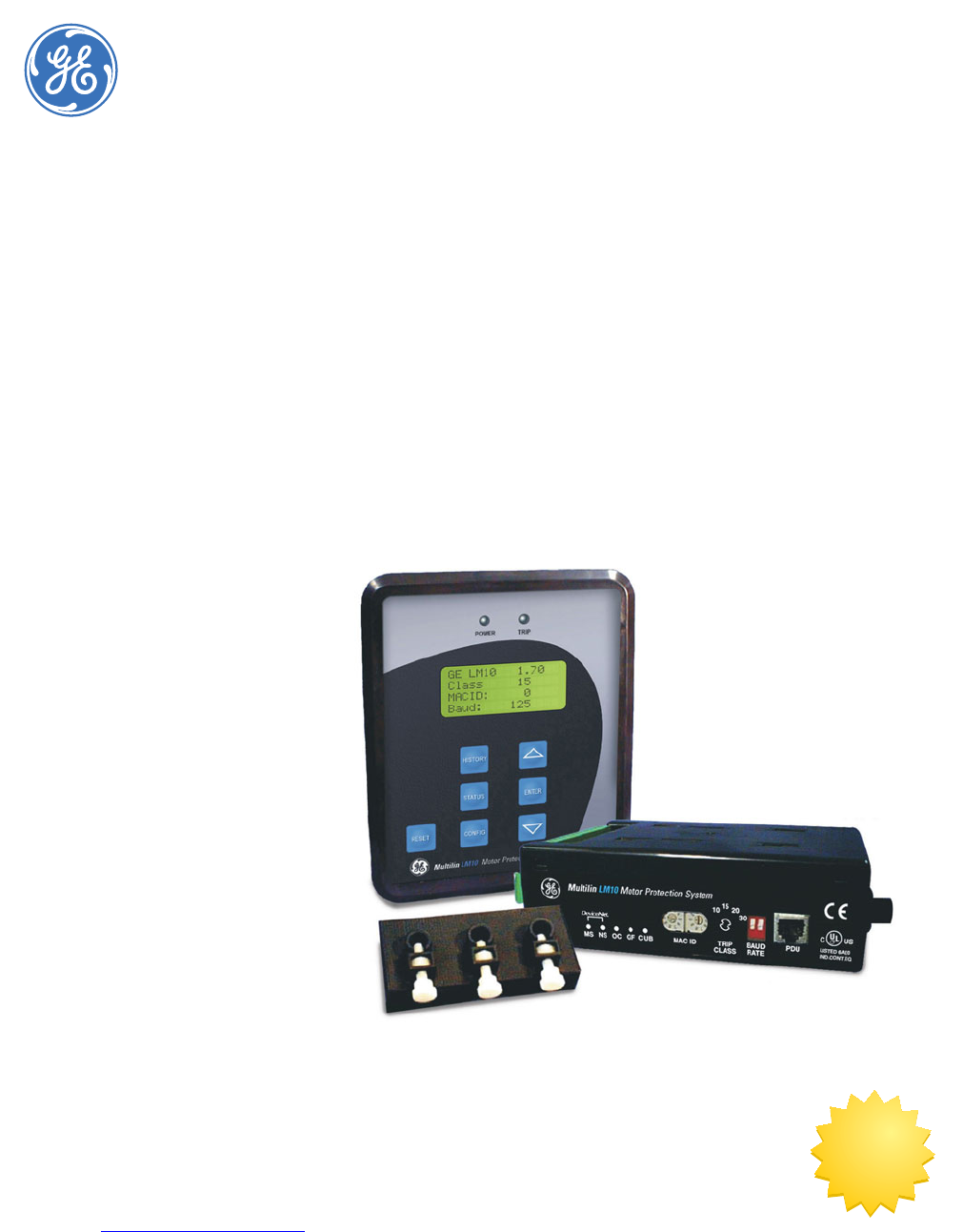
1.1.1 The LM10 Relay
The GE Multilin LM10 Motor Protection System is a modular device designed to protect
motors from various fault conditions. This device interfaces with a DeviceNet network. The
network will monitor and control the relay status and functions. The relay also has the
capability of operating in a standalone mode. Configuration can be accomplished via DIP
switches on the front of the relay.
Additionally, the relay has an interface port to communicate to the LM10 programming
and display unit (PDU). The PDU is a self-contained device consisting of a membrane switch
keypad, a liquid crystal display (LCD), and control electronics for communication with the
relay. This unit provides a method of configuring and monitoring the LM10. The PDU
incorporates an RS232 interface with a proprietary communications protocol.
DeviceNet is a registered trademark of Open DeviceNet Vendor's Association (ODVA).

1–2 LM10 MOTOR PROTECTION SYSTEM – INSTRUCTION MANUAL
OVERVIEW CHAPTER 1: INTRODUCTION
1.2 Overview
1.2.1 Features
The LM10 Motor Protection System is a microprocessor-based unit. It takes a ‘snapshot’
image of the three phases of current, one phase of voltage, and ground. The data is then
applied to the algorithms and compared to the device's configuration information. Based
on the result of the comparison, the relay may trip one or more of the on-board control
relays. When applicable, indicators will be illuminated to show the status of the device.
Additionally, up to ten trip events will be stored in non-volatile memory.
The LM10 auxiliary communications port to the PDU is an RS232 interface using a
standard four-pin RJ11 style cable. This port will allow the PDU to obtain and display any of
the real-world data that is contained in the relay as well as to configure the relay.
The LM10 Motor Protection System supports the DeviceNet protocol and can be interfaced
with the PLC DeviceNet mastercard or DCS Scanner card. It supports Polled, Change of
State (COS), Cyclic I/O Messaging, and Explicit Messaging.
1.2.2 Current and Voltage Inputs
The relay has inputs for two sets of three-phase current transformers (CTs) and one ground
CT. One set will allow for custom 27 A and 90 A CT sensor packs to be connected; the other
will allow for 75 to 800:5 A ratio CTs. Dual speed motors will require two separate CTs
connected in parallel.
A 100:1 A core-balance CT or 20 A ground fault sensor pack can be connected to the
ground CT terminals for ground current measurement.
Provisions have been made to support various CTs for the three-phase measurements.
Voltage input from the control power transformer (CPT) is conditioned and measured by
the analog-to-digital converter to determine supply voltage. This signal, in conjunction
with the current, is used to calculate power and power factor.
1.2.3 Relay Outputs
The LM10 Motor Protection System contains 4 on-board Form-C relays with NEMA C150
pilot duty ratings. Two relays should be used to control the coils of motor contactor and
one to annunciate ground fault status. An additional programmable relay is available for
fault status indications.
The two control relays are labeled “RUN 1” and “RUN 2”. These relays are enabled on
command from the control logic. If the LM10 detects a fault condition the relays will be de-
energize, causing the motors to shut down.
The ground fault relay is energized on detection of a ground fault. Upon correction of the
ground fault condition, the relay will be de-energized. The output contact can be used to
trip a breaker or annunciate to other devices.
The programmable trip relay is energized when the programmed algorithm conditions
have been met and can annunciate out to other devices.
CHAPTER 1: INTRODUCTION OVERVIEW
LM10 MOTOR PROTECTION SYSTEM – INSTRUCTION MANUAL 1–3
1.2.4 Power Supply
The LM10 Motor Protection System has an on-board power supply with a fuse that
converts the AC input to the levels necessary to operate this device. The operating range is
96 to 140 V AC, nominal 120 V control power (80% to 117%). The supply has
programmable auto-restart capability of up to 4 seconds. This also supplies necessary
power to the PDU at a TTL.
For correct measurement of power and power factor, the control power must be
connected across phase A and phase B of the three-phase power supply.
1.2.5 Block Diagram
A single line diagram for the LM10 Motor Protection System is shown below.
FIGURE 1–1: Functional Block Diagram
1–4 LM10 MOTOR PROTECTION SYSTEM – INSTRUCTION MANUAL
FEATURES CHAPTER 1: INTRODUCTION
1.3 Features
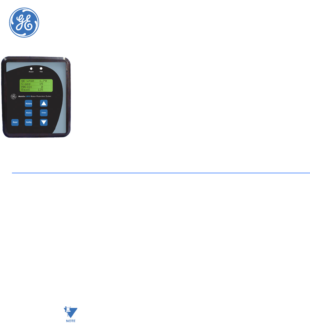
1.3.1 Programming and Display Unit
The main task of the programming and display unit (PDU) is to provide status information
to a local user. The PDU can display the requested parameter(s) on the LCD in either English
or Spanish. Additionally, the PDU can be used to configure the LM10 via the RS232 serial
communications port.
1.3.2 LED Indicators
The LM10 has five (5) LEDs on the front panel. They function as follows:
•Module Status (MS): This two-colored LED is used for the DeviceNet module status. Its
function is defined in the DeviceNet specification.
•Network status (NS): This two-colored LED is used for the DeviceNet network status.
Its function is defined in the DeviceNet specification.
•Overcurrent (OC): This red LED is illuminated when the relay detects an overcurrent
condition in one or more of the power phases.
•Ground Fault (GF): This red LED is illuminated when the relay detects a ground fault
condition.
•Current Unbalance (CUB): This red LED is illuminated when the relay detects a current
unbalance between the power phases.
1.3.3 Switches
The following switches are located on the front panel of the LM10. Changes to switch
settings will not take effect until power is cycled (on-off).
All other relay features (e.g., the CT sensor pack) can only be programmed via DeviceNet or
the RS232 configuration port.
•MAC ID: Two rotary DIP switches are used to set the DeviceNet MAC ID. Each unit on
the DeviceNet network requires a unique MAC ID. The valid ID range is from 0 to 63,
with a factory default of 0. Cycle power after any switch changes.
LED State Description
Off No power
Green Device operational
Red Unrecoverable fault
LED State Description
Off No power / not online
Flashing green Online, not connected
Green Link OK, online, connected
Flashing red Connection timeout
Red Critical link failure
CHAPTER 1: INTRODUCTION FEATURES
LM10 MOTOR PROTECTION SYSTEM – INSTRUCTION MANUAL 1–5
•Baud rate: This two-position DIP switch is used to select the DeviceNet baud rate. The
valid rates are 125K, 250K and 500K bits per second. The DIP switch is defaulted to
125K baud rate when shipped.
Changes to switch settings will not take effect until the next power cycle.
•Trip Class (TC): NEMA overload trip class is selected using a rotary DIP switch. Valid
settings are Class 10, 15, 20, or 30. To set the trip class, align the screwdriver slot with
the desired value. Do not use the triangle marker on the DIP switch. A screwdriver with
a nominal blade width of 0.094 to 0.175 inches should be used. Smaller blades could
allow the switch to be set in an invalid position.
Changes to switch settings will not take effect until power is cycled.
FIGURE 1–2: LM10 Features
Baud Rate DIP Switch Position
125 kbps down - down
250 kbps up - down
500 kbps up - up
849713A3.CDR
Display
Liquid crystal display: four lines
of 16 characters per line.
Status
The status sub-menu can display
current, motor status, Run 1 and
Run 2 data, faults, MAC ID, baud
rate, and overload class.
Reset
The relay can be reset from the
PDU, pushbutton, or the LAN.
Mounting Flexibility
The relay can be attached to the
PDU without hardware to
facilitate door mounting.
LEDS
One green LED power indicator
and a flashing red trip LED to
indicate over/undercurrent,
current unbalance, ground
fault, under/overvoltage, and
trip command.
CONFIG
The relay parameters are
programmed via the CONFIG
button. The CONFIG sub-menu is
similar to the status menu, and
allows the user to change relay
parameters: CT ratio, PT ratio,
fault settings, and time delays.
History
Displays the last ten (10) trip
records. The conditions at the
time of fault are displayed and
can be scrolled through using
the UP/DOWN arrow keys.

1–6 LM10 MOTOR PROTECTION SYSTEM – INSTRUCTION MANUAL
ORDERING CHAPTER 1: INTRODUCTION
1.4 Ordering
1.4.1 Order Codes
The order codes for the LM10 Motor Protection System are shown below.
Table 1–1: LM10 Order Codes
LM10 –D* –CT** –GF** –C* –**
Base unit LM10|||||LM10 Motor Protection System
Programmable
display unit
X||||No display unit
1||||Programmable display unit (with
cable)
Thermal overload
current transformer
XX | | | No phase current transformer
01 | | | Current sensor, NEMA starter size
1, 3-phase, 27 A
02 | | | Current sensor, NEMA starter size
2 and 3, 3-phase, 90 A
03 | | | Current sensor, NEMA starter size
4, 3-phase, 200 A
04 | | | Current sensor, NEMA starter size
5, 1-phase, 300 A
05 | | | Current sensor, NEMA starter size
6, 1-phase, 600 A
Ground fault sensor XX | | No ground fault sensor
01 | | Ground fault sensor: 20 A, 0.44"
window
02 | | Ground fault sensor: 20 A, 1.56"
window
03 | | Ground fault sensor: 20 A, 2.08"
window
04 | | Ground fault sensor: 20 A, 2.50"
window
05 | | Ground fault sensor: 20 A, 3.31"
window
06 | | Ground fault sensor: 20 A, 4.62"
window
Cable X|No cable
1 | 30-inch communication cable
from relay to PC
Reserved XX For future use

CHAPTER 1: INTRODUCTION SPECIFICATIONS
LM10 MOTOR PROTECTION SYSTEM – INSTRUCTION MANUAL 1–7
1.5 Specifications
1.5.1 Protection Elements
OVERCURRENT (ANSI 51)
Curve shapes: ..................................................NEMA class 10, 15, 20 and 30, hot and cold
Timing accuracy:............................................±5% of total trip time + 1 second
GROUND FAULT
Pickup level: .....................................................0.4 to 20.0 A in steps of 0.2
Pickup accuracy: ............................................±5% or ±0.1 A, whichever is greater
Time delay:........................................................0 to 2.5 seconds in steps of 0.1
Timing accuracy:............................................±200 ms
CURRENT UNBALANCE (ANSI 46)
Pickup level: .....................................................2 to 25% in steps of 1
Pickup accuracy: ............................................±5%
Time delay:........................................................0 to 255 seconds in steps of 1
Timing accuracy:............................................±5% of total trip time + 1 second
MECHANICAL JAM
Pickup level: .....................................................100 to 250% in steps of 1
Pickup Accuracy: ............................................±5%
Time delay:........................................................0 to 1000 seconds in steps of 5
Timing accuracy:............................................±5% of total trip time + 1 second
STALL
Pickup level: .....................................................330 to 600% in steps of 5
Pickup Accuracy: ............................................±5%
Time delay:........................................................0 to 30.0 seconds in steps of 0.5
Timing accuracy:............................................±5% of total trip time + 1 second
LOAD LOSS
Pickup level: .....................................................15 to 100% in steps of 1
Pickup Accuracy: ............................................±5%
Time delay:........................................................0 to 255 seconds in steps of 1
Timing accuracy:............................................±5% of total trip time + 1 second
UNDERVOLTAGE/OVERVOLTAGE
Undervoltage pickup level: 80% of nominal voltage (96 V)
Overvoltage pickup level: 117% of nominal voltage (140 V)
Pickup accuracy: ............................................±5%
Trip time:.............................................................0.5 second
Timing accuracy:............................................±200 ms
1.5.2 Metering
PHASE CURRENT
Resolution:.........................................................0.1 A
Range:..................................................................0.05 to 8 × CT Primary (3200.0 A max.)
Accuracy: ...........................................................±5% of full scale
1–8 LM10 MOTOR PROTECTION SYSTEM – INSTRUCTION MANUAL
SPECIFICATIONS CHAPTER 1: INTRODUCTION
AVERAGE CURRENT
Resolution: .........................................................0.1 A
Range:..................................................................0.05 to 8 × CT Primary (3200.0 A max.)
Accuracy:............................................................±5% of full scale
GROUND CURRENT
Resolution: .........................................................0.1 A
Range:..................................................................0.0 to 25.0 A
Accuracy:............................................................±0.2A when current < 4.0 A
±5% of full scale when current ≥ 4.0A
CURRENT UNBALANCE
Resolution:.........................................................1%
Range:..................................................................0 to 250%
Accuracy:............................................................±5% of full scale
VOLTAGE
Resolution:.........................................................1 V
Range:..................................................................0 to 9000 V
Accuracy:............................................................±5% of full scale
POWER
Resolution: .........................................................0.1 kW
Range:..................................................................0 to 6553.5 kW
Accuracy:............................................................±5% of full scale
POWER FACTOR
Resolution: .........................................................0.01
Range:..................................................................0.5 to 1.0
Accuracy:............................................................±5% of full scale
TRIP HISTORY
Trip history:........................................................up to last 10 trips
COUNTERS
Motor run hour counter: .............................up to 65535 hours
1.5.3 Control Functions
STARTER
Starter types:....................................................FVNR, FVR, RV, 2S1W, 2S2W, custom
Power loss autorestart: ...............................restart after power loss of 4 seconds or less
1.5.4 Inputs
POWER SUPPLY
Control power:.................................................80 to 145 V AC
Frequency:.........................................................50 and 60Hz
CURRENT
CT sensor pack:...............................................NEMA starter size 1 to 6 (27 A, 90 A primary)
Sensor Input:.....................................................0 to 0.27 V AC
Phase CT input:................................................0 to 5 A
Phase CT primary:..........................................75, 100, 120, 150, 200, 225, 250, 300, 400, 500, 600, 700,
800

CHAPTER 1: INTRODUCTION SPECIFICATIONS
LM10 MOTOR PROTECTION SYSTEM – INSTRUCTION MANUAL 1–9
Ground CT input:.............................................20 A ground fault sensor or 20:0.2 A ground fault CT
VOLTAGE
PT secondary:...................................................0 to 120 V
PT primary: ........................................................200 to 7200 V
CONTACT INPUT
Inputs:..................................................................7 fixed inputs (Run 1, Run 2, Aux sense 1, Aux sense 2,
Stop, Reset, DeviceNet control)
Recommended Supply voltage: ..............100 to 135 V AC
When the LM10 contact inputs are connected to the remote devices for the input signal via long
cables, induced voltages may be present at the input terminal of LM10 relay. The contact input
status could be detected as closed if the induced voltages are greater than 33V. Under these
situations it is recomonded to use interposing relay or to connect a resistor across the LM10
contact input terminal and ground to provide path for the induced voltages to the ground.

1–10 LM10 MOTOR PROTECTION SYSTEM – INSTRUCTION MANUAL
SPECIFICATIONS CHAPTER 1: INTRODUCTION
1.5.5 CT Dimensions
Thermal overload CT
Ground fault CT
1.5.6 Outputs
RELAY OUTPUTS
Relay pilot duty:...............................................5 A at 120 V AC
5A at 28VDC
1.5.7 Communications
DEVICENET
Functionality:....................................................group 2 slave only
Device type:.......................................................motor starter
O r d e r C o d e D e s c r i p t i o n W i n d o w
D i a m e t e r
Overall Dimensions
CT01 Current Sensor, NEMA
Starter Size 1, 3 phase,
27 amp 0.44" 4.625"x2.000"x1.375"
CT02 Current Sensor, NEMA
Starter Size 2&3, 3 phase,
90 amp 0.44" 4.625"x2.000"x1.375"
CT03 Current Sensor, NEMA
Starter Size 4, 3 phase,
200 amp 0.69" 5.60"x2.38"x1.72"
CT04 Current Sensor, NEMA
Starter Size 5, 1 phase,
300 amp 1.50" 4.50"x4.88"x4.68"
CT05 Current Sensor, NEMA
Starter Size 6, 1 phase,
600 amp 2.50" 4.57"x4.57"x4.68"
Order Code Description Window
Diameter
Overall Dimensions
GF01 Ground Fault Sensor 1&2,
2 0 a m p , 3 x 0 . 4 4 " w i n d o w s 0.44" 4.625"x2.000"x1.375"
GF02 Ground Fault Sensor 3&4,
20 amp, 1x 1.56" window 1.56" 3.53"x3.65"x2.23"
GF03 Ground Fault Sensor 5,
2 0 a m p, 3 x 2. 0 8 " w i nd o w s 2.08" 9.00"x3.94"x2.23"
GF04 Ground Fault Sensor, Limit
Amp,
20 amp, 1x 2.5" window 2.5" 4.57"x4.57"x4.68"
GF05 Ground Fault Sensor, Limit
Amp,
20 amp, 1x 3.13" window 3.13" 4.63"x5.10"x5.50"
GF06 Ground Fault Sensor, Limit
Amp,
20 amp, 1x 4.62" window 4.62" 7.00"x7.12"x6.82"

CHAPTER 1: INTRODUCTION SPECIFICATIONS
LM10 MOTOR PROTECTION SYSTEM – INSTRUCTION MANUAL 1–11
Connector type:...............................................5-pin micro-style molded male connector
Baud rate: ..........................................................125, 250 and 500 kbps via DIP switches
Mac id: .................................................................0 to 63 via DIP switches
Supports:............................................................Poll, COS and Cyclic IO, and explicit messaging
LEDs:.....................................................................network status and device status
SERIAL COMMUNICATIONS
Serial port: .........................................................RJ11 4-pin connector for Enervista LM10 Setup software
or to PDU
PANEL DISPLAY UNIT (OPTIONAL)
Display:................................................................16 character × 4 line display
1.5.8 Environmental
AMBIENT TEMPERATURE
Operating temperature:..............................0 to 60°C
Storage temperature:...................................–30 to 80°C
HUMIDITY
Humidity:............................................................up to 95% non condensing
1.5.9 Approvals/Certification
CERTIFICATION
UL: ........................................................................file number E228903 listed for USA and Canada
CE:..........................................................................conforms to EN 55011, EN 61000, IEC 68-2
DeviceNet CONFORMANCE TESTED™
1–12 LM10 MOTOR PROTECTION SYSTEM – INSTRUCTION MANUAL
SPECIFICATIONS CHAPTER 1: INTRODUCTION
LM10 MOTOR PROTECTION SYSTEM – INSTRUCTION MANUAL 2–13
LM10 Motor Protection System
Chapter 2: Installation
GE Consumer & Industrial
Multilin
Instal latio n
2.1 Wiring
2.1.1 DeviceNet
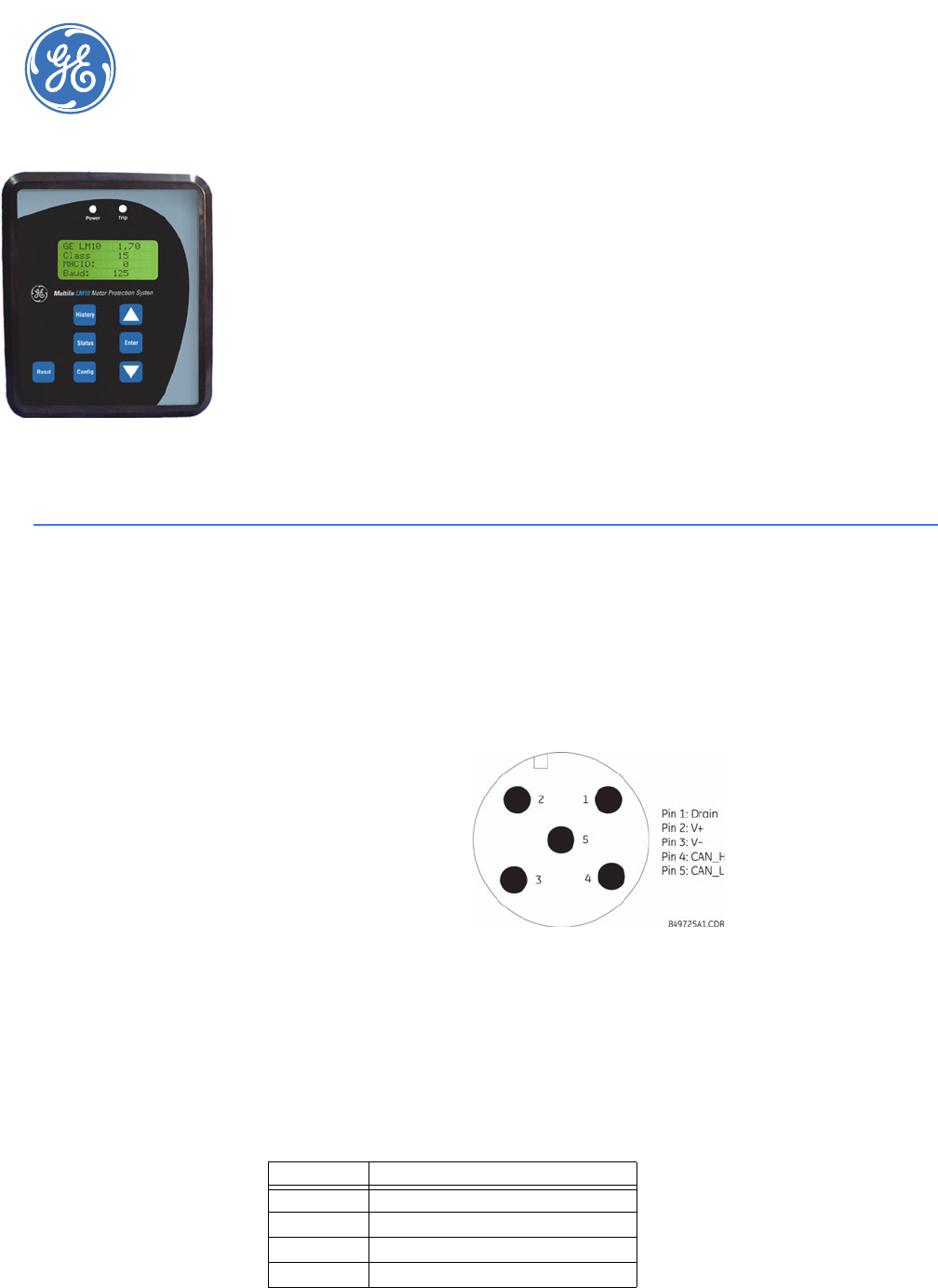
The LM10 has one micro-style (Brad Harrison style) connector that allows the purchase of
pre-built cables for attachment to the unit and the ability to daisy chain from one unit to
the next. These connectors meet all DeviceNet physical layer requirements.
FIGURE 2–1: LM10 DeviceNet Pinout
2.1.2 RS232 Port
The RS232 configuration port uses a standard RJ11 connector to interface with the
programming and display unit (PDU) or with a computer. Both communication and power
will be provided to the PDU through this connection. Standard RS232 levels are used for the
communications.
RJ11 Pin Description
1 N/A
2 Ground
3TXD
4RXD
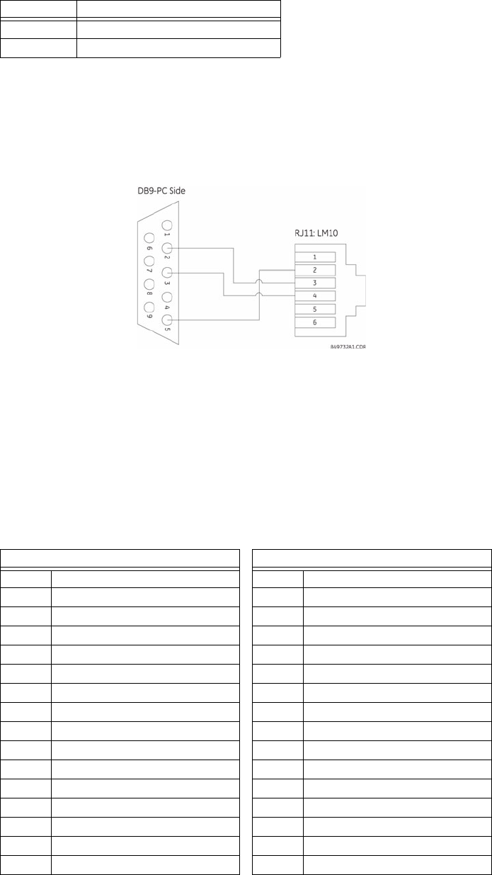
2–14 LM10 MOTOR PROTECTION SYSTEM – INSTRUCTION MANUAL
WIRING CHAPTER 2: INSTALLATION
The LM10 base unit and PDU are designed to use a maximum 36-inch cable when the PDU
is mounted door-mounted alone. A shorter cable can be used when the two units are door-
mounted together.
The connection for the RS232 serial communications port is shown in the following figure.
The EnerVista LM10 software can be used to configure and monitor the status of the LM10
through the RS232 port.
FIGURE 2–2: LM10 RS232 Pinout
2.1.3 Control Terminals
The control terminal block is a phoenix contact style 0.2-inch center, dual-row, 16 points
per row removable connector. The connector will be used to make all field connections
(other than communications and CT sensors) to the unit. The terminal block has the
following connections:
5 +5 V (PDU use only)
6 N/A
RJ11 Pin Description
Table 2–1: Control Connections
Upper Signal Row Lower Signal Row
1 120 V AC - phase 1 17 Switch input - auxiliary 2
2 120 V AC - phase 2 18 Switch input - auxiliary 1
3 Switch input - stop 19 Switch input - run 2
4 Switch input - reset 20 Switch input - run 1
5 Switch input - common 21 Switch input - DeviceNet control
6 Relay 1 N.O. - run 22 Ground fault relay N.O.
7 Relay 1 common - run 23 Ground fault relay common
8 Chassis ground 24 Programmable relay N.O.
9 Relay 2 N.O. - run 25 Programmable relay N.C.
10 Ground fault relay N.C. 26 Programmable relay common
11 Relay 2 common - run 27 5 A CT 2 phase B
12 5 A CT 1 phase B 28 5 A CT 2 phase A
13 5 A CT 1 phase A 29 5 A CT 2 phase C
14 5 A CT 1 phase C 30 5 A CT 2 common
15 5 A CT 1 common 31 No connection
16 Ground CT 1 32 Ground CT 2
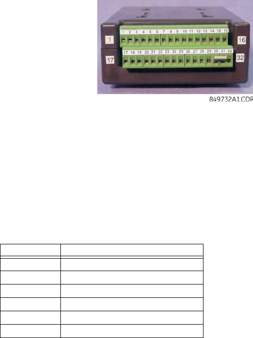
CHAPTER 2: INSTALLATION WIRING
LM10 MOTOR PROTECTION SYSTEM – INSTRUCTION MANUAL 2–15
FIGURE 2–3: LM10 Control Signal Contacts
Service hint: Remove the bottom terminal block first, using a small screwdriver in either
end. The top terminal block can then be removed using a coin or any broad-blade tool.
2.1.4 Sensor Pack Input
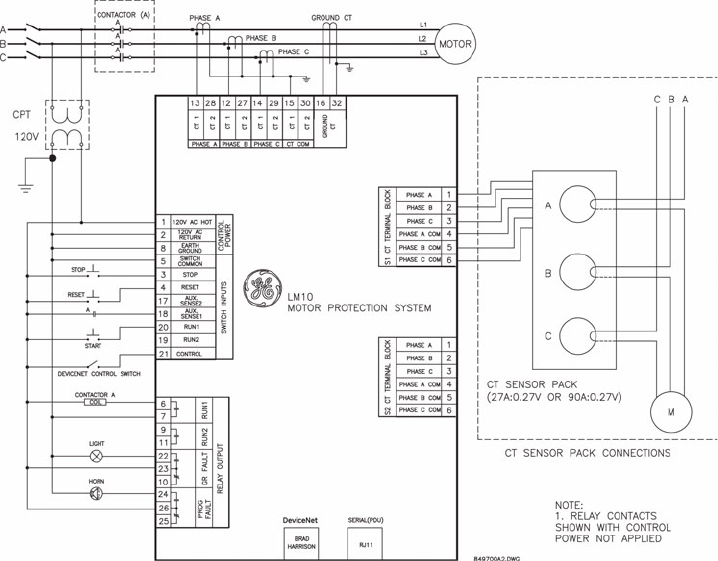
Connectors S1 and S2 are used to connect to all CT Sensor Packs. 5 A CTs connect via the
Phoenix terminal block.
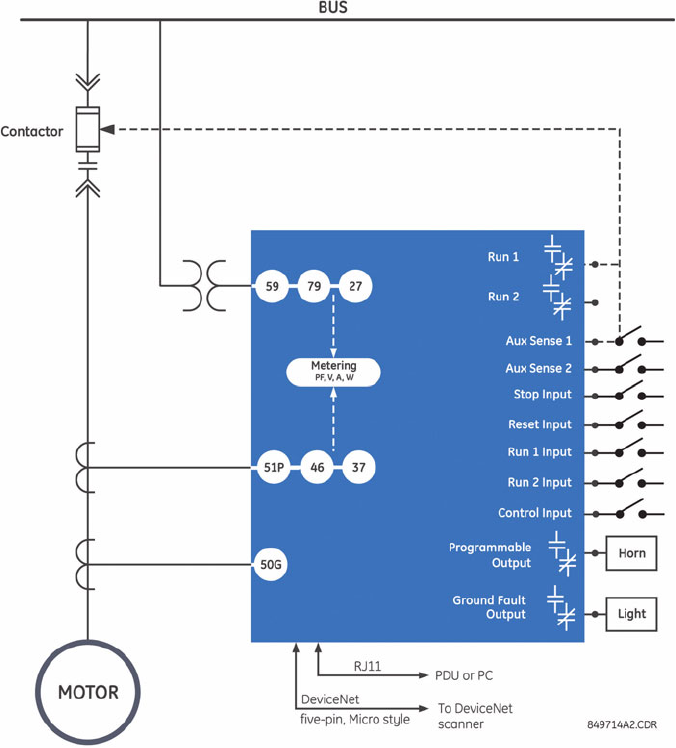
2.1.5 Wiring Diagram
A typical LM10 wiring diagram is shown below. The relay should be programmed as
“Maintained Off” (under “Other Settings”) for momentary start input. See page 4–34 for
additional details.
S1/S2 Pins Description
1CT phase A
2CT phase B
3CT phase C
4 CT phase A common
5CT phase B common
6CT phase C common
2–16 LM10 MOTOR PROTECTION SYSTEM – INSTRUCTION MANUAL
WIRING CHAPTER 2: INSTALLATION
FIGURE 2–4: LM10 Wiring Diagram
CHAPTER 2: INSTALLATION MOUNTING
LM10 MOTOR PROTECTION SYSTEM – INSTRUCTION MANUAL 2–17
2.2 Mounting
2.2.1 LM10 Mounting
Three mounting options are available.
1. The relay has four holes in the back to allow securing to a mounting plate with screws
by others.
2. When mounted in a GE Evolution Series E9000 Motor Control Center, a mounting
bracket (provided separately by GE) has been designed to suspend the LM10 base unit
inside the MCC bucket. To install, first remove the plastic mounting plate from the
LM10.
3. Front door mounting feature (see PDU Door Mount on page 2–18).
MCC hint: Grasp the bottom of the LM10 in one hand, and slide in opposite directions to
detach. Attach the mounting plate to the bracket provided using four (4) screws (not
included). Once the mounting bracket and plate are installed, slide the LM10 base unit back
onto the plate.
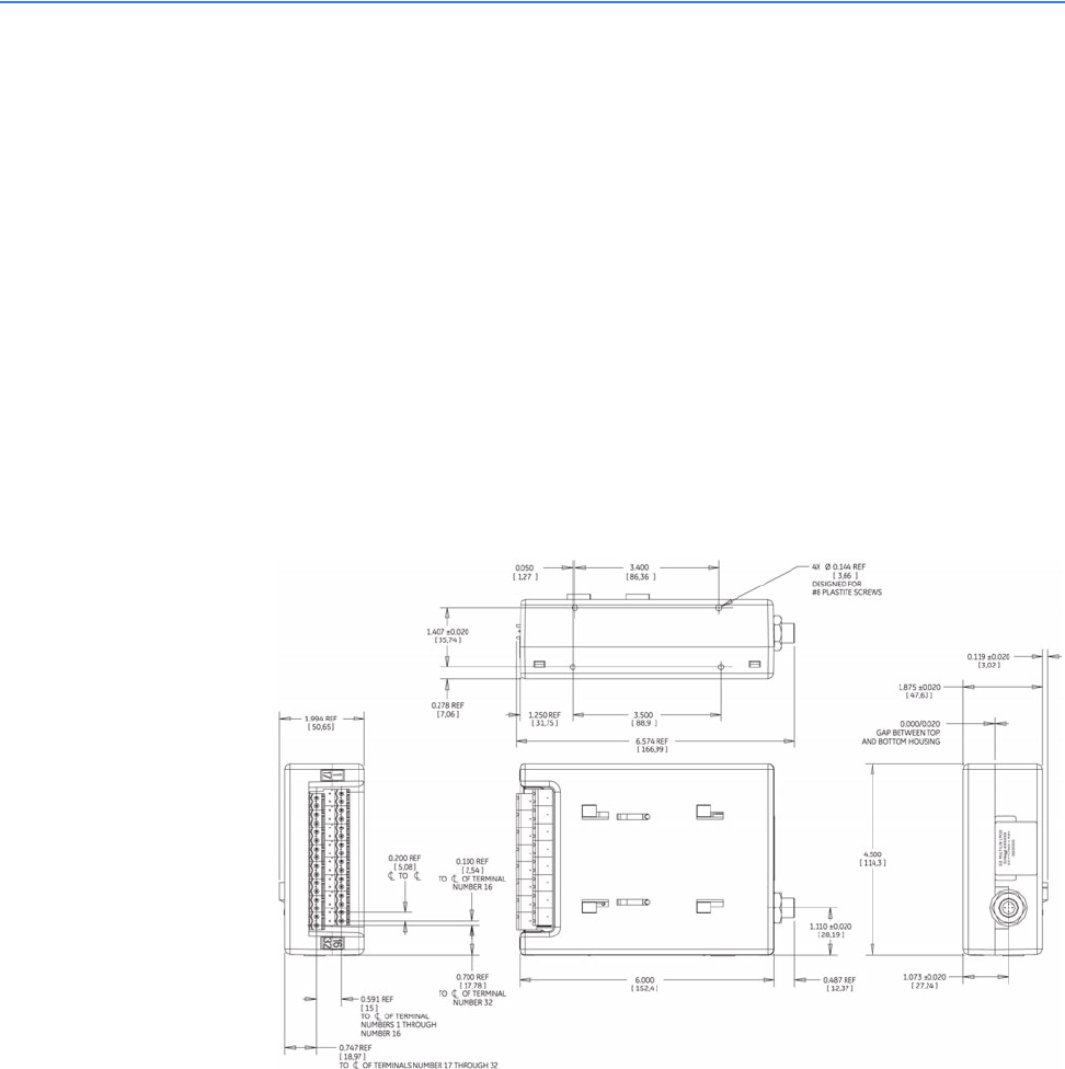
FIGURE 2–5: LM10 Base Unit Dimensions
2–18 LM10 MOTOR PROTECTION SYSTEM – INSTRUCTION MANUAL
MOUNTING CHAPTER 2: INSTALLATION
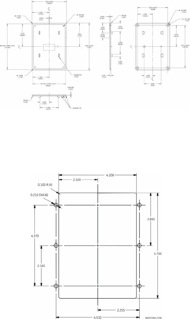
FIGURE 2–6: LM10 Backplate Dimensions
2.2.2 PDU Door Mount
The PDU can be door-mounted using the gasket and six screws provided. The rear of the
unit protrudes through a cutout and is accessible from inside the door. Recommended
cutout dimensions and screw hole locations are shown below.
FIGURE 2–7: PDU Door-mount Dimensions

LM10 MOTOR PROTECTION SYSTEM – INSTRUCTION MANUAL 3–19
LM10 Motor Protection System
Chapter 3: Interface
GE Consumer & Industrial
Multilin
Inter face
3.1 PDU Operations
3.1.1 Liquid Crystal Display
The liquid crystal display is a 5 ×8 font pixelized character type in a 16-character by 4-line
format. A yellow-green background offers good readability under direct sunlight and
normal room lighting. The display is reflective, not backlit. Display messages can be
changed to Spanish.
3.1.2 LEDs
A green LED power indicator and a flashing red LED fault indicator is provided. The green
power indicator flashes when in the Configuration mode, and the flashing red LED
indicates a trip condition.
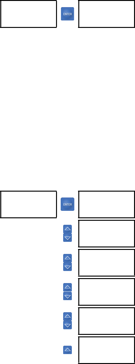
3.1.3 Keypad
The keypad consists of seven buttons used to view and select menu items displayed on the
LCD. The keypad is for program changes and data display. With the exception of testing,
the PDU is not a control keypad.
•Up and down arrows: At the main configuration screen, the up and down arrows
control the LCD contrast level. At all other screens, they are used to scroll through a list
or increase/decrease selected values.
•Enter: At the main configuration screen, pressing the Enter button toggles the LCD
display from English to Spanish. Pressing again will return the display to English. The
Enter button is used to make a selection.
•History: Pressing the History button displays the last ten (10) fault history records.
Each history record contains a snapshot of conditions when the unit last faulted. The
following items are displayed: fault type, phase currents, ground current, voltage,
3–20 LM10 MOTOR PROTECTION SYSTEM – INSTRUCTION MANUAL
PDU OPERATIONS CHAPTER 3: INTERFACE
power factor, kW, average current, and current unbalance. Pressing the History button
again advances to the next history record.
•Status: Pressing the Status button displays the current conditions of the LM10. The
following items are displayed: phase currents, ground current, voltage, kW, power
factor, average current, current unbalance, and elapsed motor hours.
•Config.:In User mode (default startup condition, no passcode entered), pressing the
Config. button displays the following programmed parameters: English or Spanish
display, CTs and CPTs, starter type, Run 1 setup, Run 2 setup, time delays, other
settings, auxiliary relay faults, and passcode/login.
In Configuration mode (after proper passcode entered), the same Config screens are
available to edit. In addition, the following restricted-access options are displayed: run
operations and restore factory default configuration.
•Reset: At the main startup screen, the Reset button clears fault conditions, thereby
allowing the motor to be ready to restart. At all other screens, pressing the Reset
button brings the previous menu.

CHAPTER 3: INTERFACE PDU SCREENS AND MENUS
LM10 MOTOR PROTECTION SYSTEM – INSTRUCTION MANUAL 3–21
3.2 PDU Screens and Menus
3.2.1 Main Startup Screen
The main startup screen displays the following information. These parameters are not
programmable via serial communications, but rather are displayed for convenience. See
Switches on page 1–4 for setting instructions.
• PDU software version displayed briefly, then replaced by the LM10 software version
• Trip class
•MAC ID
•Baud rate
3.2.2 History Record and Status Screens
See Keypad on page 3–19 for details on the history record and status screens.
3.2.3 Configuration Menu
See Keypad on page 3–19 for details on the configuration menu list. The configuration
menu is used to set all the programmable parameters outlined in Configuration Settings on
page 4–29.
•CTs and CPTs Sub-menu: This menu and its sub-menus are used to select Control
Power Transformer (CPT), Current Transformer (CT) or Sensor Pack, and the number of
turns through the CT.
•Starter Type Sub-menu: This menu is used to select Motor Starter Type.
•Run 1 and Run 2 Setup Sub-menus: This Run 1 menu is used to set full load current
(FLA) for Run 1. It also contains sub-menus for enable/disable and configures the
following optional faults: ground fault, jam, stall, current unbalance, and load loss.
Each fault is configurable not only in magnitude, but also in time delay in which that
condition is allowed to exist before the LM10 trips.
The Run 2 Setup menu is laid out identically to Run 1 menu. Unless a custom motor
type is selected, Run 2 setup is not necessary.
The full-load current will auto-populate if “Two-Speed” is selected. 2S1W will provide a
4:1 ratio of the FLA and 2S2W will set the FLA to a 2:1 ratio.
Only one relay at a time can be on.
•Time Delays Sub-menu: The following time delays are set using this menu:
Auxiliary sense 1 (contactor closed; opened detects welded contacts)
Auxiliary sense 2 (contactor closed; opened detects welded contacts)
Run 1 to Run 2 (delay between forward and reverse or between speeds)
3–22 LM10 MOTOR PROTECTION SYSTEM – INSTRUCTION MANUAL
PDU SCREENS AND MENUS CHAPTER 3: INTERFACE
Run 2 to Run 1 (delay between forward and reverse or between speeds)
•Other Settings Sub-menu: The Other Settings menu is used to enable/disable the
following: under/overvoltage, maintained vs. momentary switches, auto restart,
DeviceNet fault, and 50 vs. 60 Hz system. It is also used to select the data grouping
which is read through DeviceNet polling and to reset elapsed time meter. See Chapter
4 for details.
•Auxiliary Relay Faults Sub-menu: The auxiliary or programmable relay can be
triggered upon any or all of the following fault conditions: overcurrent, jam, stall,
current unbalance, auxiliary sense fault, load loss, power failure, DeviceNet fault, and
under/overvoltage.
•Passcode, Login Screen: The unit has three passcode levels – User, Configurator, and
Calibrator (shown as "change" on the PDU display). The default condition is User mode.
It is necessary to login as Configurator in order to change any parameters. The unit is
not meant for field calibration, therefore Calibration mode shall not be discussed in
this Guide.
To enter a passcode press Config. and scroll down to the Pass Code field. Press enter
to select, then use the up/down arrows to scroll to Config: press enter again to login.
An incorrect passcode will force the login back to User.
The default Configurator passcode is “0” and can only be changed when in the Config
mode. The menu item to change the passcode will become active after a successful
login attempt. The Pass Code is a numeric value between 0 and 65535.
•Run Operations Screen: Press in Config. Mode and scroll down to Run Operation, this
screen allows control of the Run, Stop, and Reset commands via the PDU. It may be
used for test purposes.
•Restore Factory Configuration Screen: This screen, available only to Configurator or
higher login, resets all parameters to factory defaults. The PDU will prompt the user to
confirm the request prior to resetting parameters. Default settings are listed in Table 3
Configuration Parameters.
CHAPTER 3: INTERFACE ENERVISTA LM10 SOFTWARE
LM10 MOTOR PROTECTION SYSTEM – INSTRUCTION MANUAL 3–23
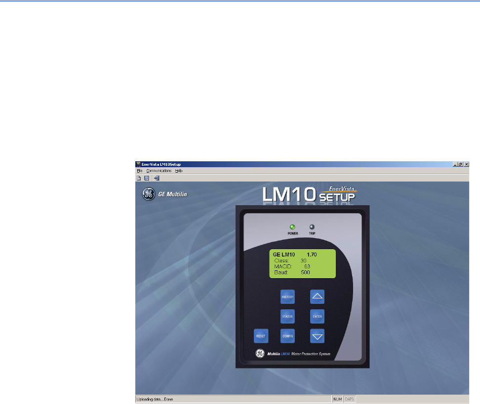
3.3 EnerVista LM10 Software
3.3.1 Description
The EnerVista LM10 software is intended as an interface to the GE Multilin LM10 Motor
Protection System. It has all the capabilities of the GE Multilin LM10 Motor Protection
System, although some of the operations may differ slightly. The major difference is
configuration parameters are not directly changed from the PDU screen, they must be
downloaded after modifying. Also data values can be entered directly with the keyboard
digits.
FIGURE 3–1: Main software screen
3.3.2 Functional Details
The EnerVista LM10 software has three menus: File, Communication and Help.
The File menu has following submenu items:
•New: Loads the memory with default values for the LM10 configuration parameters.
•Load: Loads the selected file and restores the LM10 configuration and communication
parameters from the file.
•Save: Saves the LM10 configuration and communication parameters to the selected
or entered file.
•Exit: Closes the program.
The Communication menu has the following submenu items:

3–24 LM10 MOTOR PROTECTION SYSTEM – INSTRUCTION MANUAL
ENERVISTA LM10 SOFTWARE CHAPTER 3: INTERFACE
•Download: Sends the configuration parameters from memory to the connected LM10.
Note that you must be logged into the LM10 as a configurator to download
configuration parameters.
•Upload: Gets the configuration parameters from the connected LM10 and saves them
in memory.
•Port: Shows the available communications ports. The current selected COM port is
indicated by a check mark. The green power LED indicates that communication is
currently established with the LM10.
The Help menu has following submenu items:
•Manual: Opens the enerVista LM10 setup software help file.
•About: Displays the enerVista LM10 setup software version and information.
The EnerVista LM10 software uses hot keys for the following that equate to a mouse click
on the PDU keys.
Table 3–1: EnerVista Hot Keys
Keys on PDU Hot Keys
Reset Esc, R, r
Status S, s
History H, h
Config C, c
Up arrow 'Up arrow' key
Down arrow 'Down arrow'
Enter 'Enter' key

LM10 MOTOR PROTECTION SYSTEM – INSTRUCTION MANUAL 4–25
LM10 Motor Protection System
Chapter 4: Functionality
GE Consumer & Industrial
Multilin
Functional ity
4.1 Overcurrent Fault Conditions
4.1.1 Descriptions
When current for any of the three phases becomes greater than the nominal full load
current (FLA), the unit calculates time to trip. The FLA, trip class, CT ratio and number of
passes/turns through the CT, and current input readings are taken into account. Separate
algorithms are used for “cold” and “hot” motors. Since the LM10 does not measure
temperature directly, motor condition is extrapolated from operating current versus the
FLA setting.
The FLA value can be set from 1.2 to 800 A in steps of 0.1. This fault value is monitored
continuously and can not be disabled.
The motor “hot” condition is determined based a variable algorithm. Once a fault condition
is reached, the unit may not be Reset until an appropriate cool-down period has elapsed.
This is once again calculated based on FLA, trip class, CT ratio and number of passes/turns
through the CT, and current input readings.
The time to trip is a function of percent overcurrent, trip class, and motor condition (cold or
hot). The current level must exceed 1.2 ×FLA for the trip timeout to run. This time is
cumulative and will not time in unless the level drops below 1.0 ×FLA.
A class 10 motor has the shortest trip times while a class 30 has the longest. The trip class
should be selected based on motor size and type (see Switches on page 1–4 for details on
setting the trip class).
The LM10 monitors average current of the three phases over time to determine the motor
condition.
4–26 LM10 MOTOR PROTECTION SYSTEM – INSTRUCTION MANUAL
OVERCURRENT FAULT CONDITIONS CHAPTER 4: FUNCTIONALITY
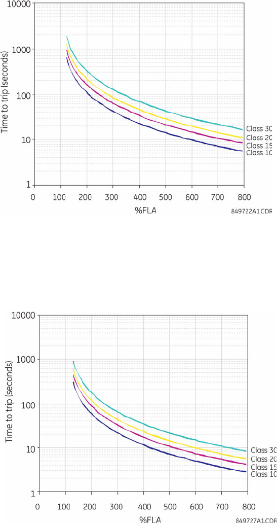
FIGURE 4–1: Cold Motor Trip Curves
FIGURE 4–2: Hot Motor Trip Curves
CHAPTER 4: FUNCTIONALITY OVERCURRENT FAULT CONDITIONS
LM10 MOTOR PROTECTION SYSTEM – INSTRUCTION MANUAL 4–27
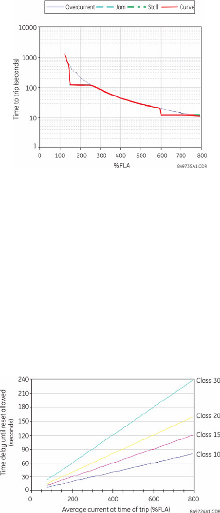
4.1.2 Trip Curves Example
A trip curves example with jam and stall enabled is shown below. In this example, we have
trip class 20, cold motor, with jam at 150% FLA for 120 seconds, and stall at 600% FLA for
12 seconds.
FIGURE 4–3: Trip Curve with Jam and Stall Enabled
The LM10 will trip on a jam or stall condition if these faults are enabled (see Run 1 and Run
2 Setup on page 4–32). The overcurrent curve cannot be disabled. Therefore, if the jam or
stall values are set greater than the time allowed by the standard trip curve, the LM10 will
trip before a jam or stall condition can be reached.
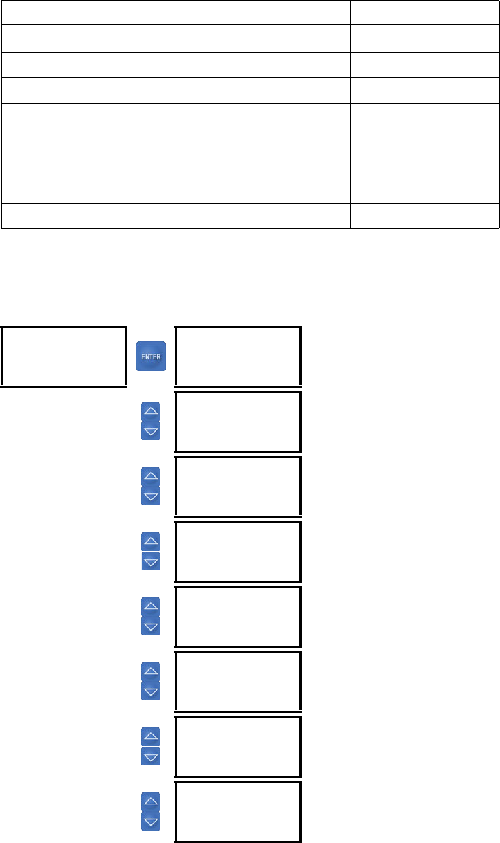
Upon an overcurrent, jam, or stall fault, the LM10 forces a cool-down period before the
motor may be restarted. The time to reset is calculated as a function of the trip class and
percent of full load current (FLA) at the time of the trip. For example, a class 30 motor
tripping on a 6 ×FLA fault will take 9 times longer before it is ready to reset than a class 10
motor tripping on a 2 ×FLA fault.
FIGURE 4–4: Cool Down Times
4–28 LM10 MOTOR PROTECTION SYSTEM – INSTRUCTION MANUAL
OVERCURRENT FAULT CONDITIONS CHAPTER 4: FUNCTIONALITY
While the motor is in the cool-down time delay, the PDU status screen will display the fault
type followed by a number decrementing from 99. When the number counts down to 0, the
message “Ready to Run” will be displayed to indicate the RESET button may be pressed.
Once the LM10 is successfully reset, the user may activate the run command.

CHAPTER 4: FUNCTIONALITY CONFIGURATION SETTINGS
LM10 MOTOR PROTECTION SYSTEM – INSTRUCTION MANUAL 4–29
4.2 Configuration Settings
4.2.1 Overview
An overview of the LM10 programmable parameters is shown below.
Table 4–1: LM10 Programmable Parameters
Parameter Range/Options Default Reference
Control power transformer
CPT ratio 200:120, 240:120, 480:120, 600:120,
2400:120, 3000:120, 3300:120,
4200:120, 4800:120, 5400:120,
6000:120, 7200:120
240:120 page 4–31
Current transformer
CT / sensor pack 27 A Sensor Pack, 90 A Sensor Pack,
75:5, 100:5, 150:5, 200:5, 225:5,
250:5, 300:5, 400:5, 500:5, 600:5,
700:5, 800:5
100:5 Ratio page 4–31
CT turns 1 to 4 in steps of 1 1 page 4–31
Starter type FVNR, FVR, RV, 2S1W, 2S2W, Custom FVNR page 4–32
FLA (RUN1 and RUN2) 1.2 to 800 A in steps of 0.1 100.0 A page 4–32
Ground fault level 0.4 to 20 A in steps of 0.2 or Off Off page 4–32
Ground fault timeout 0 to 2.5 seconds in steps of 0.1 0.5 sec. page 4–32
Jam level 100 to 250% of FLA in steps of 1 or
Off Off page 4–32
Jam timeout 0 to 1000 seconds in steps of 5 120 sec. page 4–32
Stall level 330 to 600% of FLA in steps of 5 or
Off Off page 4–32
Stall timeout 0 to 30 seconds in steps of 0.5 10 sec. page 4–32
Current unbalance level 2 to 25% of FLA in steps of 1 or Off Off page 4–32
Current unbalance
timeout 0 to 255 seconds in steps of 1 5 sec. page 4–32
Load loss level 15 to 100% of Full Load in steps of 1
or Off Off page 4–32
Load loss timeout 0 to 255 seconds in steps of 1 60 sec. page 4–32
Undervoltage 96 V fixed (trip delay time 0.5 sec.) 96 V page 4–34
Overvoltage 140 V fixed (trip delay time 0.5 sec.) 140 V page 4–34
Aux. sense 1 time delay
Aux. sense 2 time delay 0.1 to 25.0 sec. in steps of 0.1 for ON
state; 0.0 sec. for Disabled 0.4 sec. page 4–34
Run 1 to Run 2 time delay;
Run 2 to Run 1 time delay 0 to 600 seconds in steps of 1 0 sec. page 4–34
Under/overvoltage enable Off, On On page 4–34
Maintained input switches Off = momentary,
On = maintained/latched Off page 4–34
Auto restart Off, On Off page 4–34
4–30 LM10 MOTOR PROTECTION SYSTEM – INSTRUCTION MANUAL
CONFIGURATION SETTINGS CHAPTER 4: FUNCTIONALITY
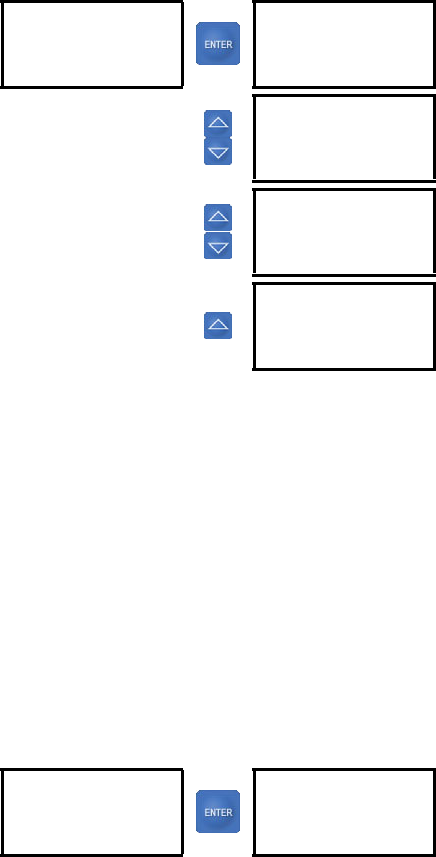
4.2.2 Main Menu
The main menu for the configuration settings is shown below. Press the CONFIG key to
access these settings.
DeviceNet fault Off, On Off page 4–34
50 Hz system Off = 60Hz, On = 50Hz Off page 4–34
Poll data 1, 2, 3, 4 1 page 4-34
Reset run hours Resets on selection N/A page 4–34
Administration control Off, On On page 4–34
Auxiliary relay faults
independently selectable OvrCur, JAM, STALL, UnBalCur,
AuxSense, LoadLoss, PwrFail,
DevNet, Voltage
All Off page 4–36
Restore factory defaults Resets on selection N/A page 4–38
Table 4–1: LM10 Programmable Parameters
Parameter Range/Options Default Reference
GE LM10 1.70
Class: 10
MAC ID: 1
Baud: 500
Configuration
ENGLISH
CTs & CPTs
Starter Type
See page –31.
Configuration
CTs & CPTs
Starter Type
RUN 1 Setup
See page –31.
Configuration
Starter Type
RUN 1 Setup
RUN 2 Setup
See page –32.
Configuration
RUN 1 Setup
RUN 2 Setup
Time Delays
See page –32.
Configuration
RUN 2 Setup
Time Delays
Other Settings
See page –32.
Configuration
Time Delays
Other Settings
Aux Rly Faults
See page –34.
Configuration
Other Settings
Aux Rly Faults
Passcode, Login
See page –34.
Configuration
Aux Rly Faults
Passcode,login
Run Operations
See page –36.
CHAPTER 4: FUNCTIONALITY CONFIGURATION SETTINGS
LM10 MOTOR PROTECTION SYSTEM – INSTRUCTION MANUAL 4–31
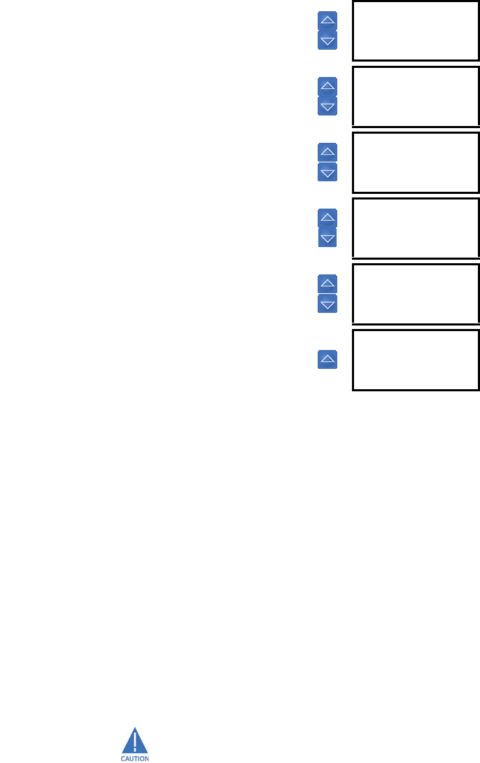
4.2.3 Language
PATH: Configuration Ø ENGLISH/SPANISH
This setting selects the language (either English or Spanish) to display on the PDU interface.
4.2.4 CTs and CPTs
PATH: Configuration ØØ CTs & CPTs
The CT and CPT settings are described below.
•Ctrl Pwr Xformer (control power transformer (CPT)): Select a CPT ratio from the choices
provided. The default CPT ratio is 240:120.
•Cur Xfr / Sensor (current transformer): Select a CT ratio from the choices provided.
The first two menu choices refer to sensor packs, while the remaining options are
ratios of compatible CTs that might be used with the LM10.
•CT Turns: The CT may be configured so that wires are passed through the CT multiple
times to increase values. This changes the effective CT ratio. Select a value between 1
and 4 for the number of turns (passes) through the CT.
Configuration
Passcode, Login
Run Operations
Factory default
See page –37.
Configuration
Run Operations
Factory default See page –38.
Configuration
Factory deflt See page –38.
Configuration
ENGLISH
CTs & CPTs
Starter Type
Configuration
ENGLISH
SPANISH
Range: SPANISH, ENGLISH
Configuration
CTs & CPTs
Starter Type
RUN 1 Setup
CTs_CPTs
Ctrl Pwr Xformer
Range: 200:120; 240:120, 480:120,
600:120, 2400:120, 3000:120,
3300:120, 4200:120, 4800:120,
5400:120, 6000: 120, 7200:120
CTs_CPTs
Cur Xfr / Sensor
Range: 27 FLA SenPak, 90 FLA SenPak,
75:5, 100:5, 120:5, 150:5, 200:5,
225:5, 250:5, 300:5, 400:5, 500:5,
600:5, 700:5, 800:5
CTs_CPTs
CT Turns: 1
Range: 1 to 4 in steps of 1
4–32 LM10 MOTOR PROTECTION SYSTEM – INSTRUCTION MANUAL
CONFIGURATION SETTINGS CHAPTER 4: FUNCTIONALITY
4.2.5 Starter Type
PATH: Configuration ØØØ Starter Type
Select the motor type from the list. The choices are as follows:
• “FVNR” (full voltage non-reversing)
• “FVR” (full voltage reversing)
• “RV” (reversing)
• “2S1W” (two-speed one winding; Run-2, 4:1 ratio of Run-1)
• “2S2W” (two-speed two winding; Run-2, 2:1 ratio of Run-1)
•“Custom”
Any of the first five allows the LM10 to automatically populate required fields (FLA, etc.) for
Run 2 based on Run 1 data. These fields are automatically populated, even for full voltage
non-reversing motors, and do not require a separate configuration step. Even if logged
into configuration mode, the LM10 will not accept Run 2 configuration changes unless a
Starter Type of “Custom” is selected. The “Custom” value is for non-standard applications
where Run 2 is not a set ratio of Run 1 and may be independently configured.
4.2.6 Run 1 and Run 2 Setup
PATH: Configuration ØØØØ Run 1 Setup
The Run 1 settings are described below. The settings for Run 2 setup are identical.
Configuration
Starter Type
RUN 1 Setup
RUN 2 Setup
Starter Type
FVNR .*
Range: FVNR, FVR, RV, 2S1W, 2S2W,
Custom
Configuration
RUN 1 Setup
RUN 2 Setup
Time Delays
RUN 1 Setup
FLA: 27.0
Range: 1.2 to 800.0 A in steps of 0.1
RUN 1 Setup
Ground Setup
Range: 0.4 to 20 A in steps of 0.2 or
Disabled for Ground Setup Fault;
0 to 2.5 s in steps of 0.1 for
Ground Setup Time Delay
RUN 1 Setup
JAM Setup
Range: 100 to 250% in steps of 1 or
Disabled for JAM Setup Fault;
0 to 1000 s in steps of 5 for JAM
Setup Time Delay value
RUN 1 Setup
STALL Setup
Range: 330 to 600% in steps of 5 or
Disabled for STALL Setup Fault;
0 to 30.0 s in steps of 0.5 for
STALL Setup Time Delay value
RUN 1 Setup
CurUnB Setup
Range: 2 to 25% in steps of 1 or
Disabled for CurUnB Setup Fault
value; 0 to 255 s in steps of 1 for
CurUnB Setup Time Delay value
RUN 1 Setup
LdLoss Setup
Range: 15 to 100% in steps of 1 or
Disabled for LdLoss Setup Fault
value; 0 to 255 s in steps of 1 for
LdLoss Setup Time Delay value

CHAPTER 4: FUNCTIONALITY CONFIGURATION SETTINGS
LM10 MOTOR PROTECTION SYSTEM – INSTRUCTION MANUAL 4–33
•FLA (full load current) The LM10 Motor Protection System is designed to work in
conjunction with a spectrum of motor starters. Therefore it handles full load currents
ranging from 1.2 to 800 amps. The correct FLA for the motor in use must be
programmed for relay protection to function properly.
Enter the full load current (FLA) of the motor. The LM10 will not accept full load currents that
exceed the CT or sensor pack rating; however, lower values are acceptable. For best results,
enter the proper FLA for the motor being used. Refer to Overcurrent Fault Conditions on
page 4–25 for additional details.
•Ground Setup: A zero-sequencing ground fault can be enabled to trip and operate a
separate ground fault relay when ground fault current exceeds the Ground Setup
Fault setpoint. The Ground Setup Time Delay setting is from 0.5 to 2.5 seconds.
Ground current can be continuously monitored at the PDU or over the network.
A ground fault CT or sensor shall be connected for this protection.
•JAM Setup: According to NEMA or IEC MG 1-1998 part 12, page 21, “polyphase motors
600 V or less not exceeding 500 hp shall be capable of withstanding a current not less
than 1.5 times the full load rated current for not less than two minutes when the
motor is at normal operating temperature.” For relatively low overcurrent conditions,
particularly on higher NEMA class motors, trip times could be considerably longer than
2 minutes. Therefore, a separate jam fault is available as the standard time
overcurrent curve may not protect in this range.
The user may set a JAM Setup Fault level of 100 to 250% of FLA or disable this function.
The default setting is set to disabled.
The overcurrent curve cannot be disabled. Therefore, if the JAM Setup Time Delay is set
greater than the time allowed by the standard trip curve, the LM10 will trip before a Jam
condition can be reached. See Trip Curve with Jam and Stall Enabled on page 4–27 for an
example of the effect of trip times.
•STALL Setup: Cold motor trip times for a 6 ×FLA fault are determined by trip class. For
example, a NEMA class 20 motor at 6 ×FLA would trip in 20 seconds. A separate Stall
fault is available which would allow the user to reduce the trip time for large
overcurrent situations.
The user may set a STALL Setup Fault level of 330 to 600% of FLA or disable this function.
The default setting is disabled.
The overcurrent curve cannot be disabled. Therefore, if the STALL Setup Time Delay is set
greater than the time allowed by the standard trip curve, the LM10 will trip before a stall
condition can be reached. See Trip Curve with Jam and Stall Enabled on page 4–27 for an
example of the effect of trip times.
•CurUnB Setup (current unbalance setup): The LM10 monitors the three current phases
and trips if the phases are unbalanced. In addition to phase A, B, and C current, this
function takes FLA, CT ratio and number of passes/turns through the CT into account.
If the average current exceeds FLA, then this average value is used in the formula
instead of the FLA value. The formula is:
(EQ 4.1)
The next formula uses the largest Δ of the three phases.
(EQ 4.2)
The default CurUnB Setup Fault value is “Disabled” since not every application will require
current unbalance monitoring. The current unbalance is programmable between 2 to 25%
of FLA.
Δphase current average current–=
unbalance level ΔFLA⁄()100%×=
4–34 LM10 MOTOR PROTECTION SYSTEM – INSTRUCTION MANUAL
CONFIGURATION SETTINGS CHAPTER 4: FUNCTIONALITY
A 6% voltage unbalance equates to a roughly 25% current unbalance and will frequently
cause motor damage.
•LdLoss Setup (load loss setup): Load loss is based on watts, defined as follows:
(EQ 4.3)
The power factor is determined using the phase relationship between voltage and phase C
current readings. Full load would be when the average current is at FLA, voltage is at
nominal value, and power factor equals 0.85. This would equate to a load loss level of
100%. The LdLoss Setup Fault trip point is programmable as a percentage of this value.
The motor would need to drop below this level for the preset time to cause the load loss
fault. The relay is shipped with this option disabled.
4.2.7 Time Delays
PATH: Configuration ØØØØØ Time Delays
The time delay settings are described below.
•AuxSns1 and AuxSns2 (auxiliary sense failure): Should the LM10 detect that a
contactor did not open/close according to its command, an auxiliary sense (AuxSns)
trip failure will be recorded in the fault record and shut down the run relay. This fault is
factory preset at 0.4 seconds. The delay time for closing the relay can be changed
however opening time is set at a constant 0.4 seconds to detect contact welding.
Applications requiring a delay between the run command and the starter pulling-in can be
accommodated using this feature (for example, fans requiring damper closer before
running). The AuxSns1 and AuxSns2 time delays can be set to match the damper closure
time.
4.2.8 Other Settings
PATH: Configuration ØØØØØØ Other Settings
watts 1.732 average current voltage power factor×××=
Configuration
Time Delays
Other Settings
Aux Rly Faults
Time Delays
AuxSns1 .4
Range: 0.1 to 25.0 s in steps of 0.1 or
Disabled
Time Delays
AuxSns2 .4
Range: 0.1 to 25.0 s in steps of 0.1 or
Disabled
Time Delays
Run1-Run2 0
Range: 0 to 600 s in steps of 1
(0 to 180 s in steps of 1 for
revisions 1.40 and lower)
Time Delays
Run2-Run1 0
Range: 0 to 600 s in steps of 1
(0 to 180 s in steps of 1 for
revisions 1.40 and lower)
Configuration
Other Settings
Aux Rly Faults
Passcode,login
Other Settings
U/O Volt En off
Range: On, off. Not available for
revisions 1.40 and lower
CHAPTER 4: FUNCTIONALITY CONFIGURATION SETTINGS
LM10 MOTOR PROTECTION SYSTEM – INSTRUCTION MANUAL 4–35
One or more optional faults may be enabled after the basic functions are configured.
•U/O Volt En (undervoltage/overvoltage enable): This setting enables or disables the
under/overvoltage element. LM10 revisions 1.40 and lower do not support this setting.
Maximum and minimum voltage trip points are hard coded in the device and are not user
programmable. These points are approximately 80% and 117% of nominal voltage. This
corresponds to 96 V and 140 V with 120 V nominal voltage.
•Maintained (maintained switching): This setting distinguishes between maintained
(latched) versus momentary AC input switches. This is only applicable to Manual
control, and has no effect on control via DeviceNet. The default setting is “off” for
momentary switches. No seal in contact is required. In the maintained mode a run
switch must stay closed if opened the LM10 will stop the motor. The stop switch input
for safety reasons will interrupt the run relay in maintained or momentary mode. If the
run switch is on when the stop command is given, it will need to be turned off and
back on to get the motor running again. The stop command also interrupts the run
relay if controlled by the network. The network will need to send another run
command to restart the motor.
When using the maintained switching feature, potential safety hazards must be
considered and an appropriate setup chosen for each individual application.
•Auto Restart (power loss when running): The LM10 will be able to recover from a
power loss of up to 4 seconds and return to its previous run state. Enabling
autorestart allows the unit to restart the motor without operator intervention using a
momentary run input. The default condition is “off” – this would require the operator
to restart the motor after the LM10 regains power.
Other conditions may interfere with this operation. A fault condition like voltage or
DeviceNet may trip the LM10. Under the voltage condition the LM10 would be faulted
Other Settings
Maintained off
Range: on, off
Other Settings
Auto Restart off
Range: on, off
Other Settings
DevNet Fault on
Range: on, off
Other Settings
50Hz Sys off
Range: on, off
Other Settings
Poll Data 1
Range: 1, 2, 3, 4. Not available for
revisions 1.40 and lower
Other Settings
Reset Run Hrs.
Range: on, off

4–36 LM10 MOTOR PROTECTION SYSTEM – INSTRUCTION MANUAL
CONFIGURATION SETTINGS CHAPTER 4: FUNCTIONALITY
prior to power loss and not be in run when power is lost, therefore no run state to
restart. With the DeviceNet fault enabled, the power recovery would reset the
DeviceNet connections and the DeviceNet would act as if it's not communicating thus
a DeviceNet fault.
Potential safety hazards must be considered and the appropriate setup chosen for each
individual application.
•DevNet Fault (DeviceNet fault): If enabled, the LM10 will consider DeviceNet network
failures as a fault, tripping relay(s) and recording into the history record. Default
condition is enabled.
•50Hz Sys (50 Hz system): The default setting is for a 60 Hz system; use this menu item
to select a 50 Hz system instead. This does effect the sampling buffer and internal
calculations. Setting this improperly will result in some inaccuracies.
•Poll Data (poll data group): This setting selects the pre-defined group of parameters in
the DeviceNet input poll data. Refer to Poll Data on page 5–45 for details. LM10
revisions 1.40 and lower do not support this setting.
For this setting, group 1 is 7 bytes, group 2 is 12 bytes, group 3 is 22 bytes, group 4 is 7
bytes.
Poll group 4 option (7 bytes) is available only for firmware rev 1.70 and higher.
If PDU v1.70 or higher is used for LM10 firmware v1.6x and lower, Poll Data group 4 (which
is unavailable in firmware v1.6x and lower) will be displayed in the PDU but cannot be set
to the MPR unit.
•Reset Run Hrs (reset motor running hourse timer): The user may desire to reset the
motor running hours after replacement or maintenance. Note that hours are stored in
full-hour increments up to 65535. Typical bearing life is less than 50000 hours. Please
note that shutting down the unit will lose any partial hour accrued.
4.2.9 Auxiliary Relay Faults
PATH: Configuration ØØØØØØØ Aux Relay Faults
Configuration
Aux Rly Faults
Passcode,login
Run Operations
Aux Relay Faults
Over Current off
Range: on, off
Aux Relay Faults
JAM off
Range: on, off
Aux Relay Faults
STALL off
Range: on, off
Aux Relay Faults
Unbalance Cur off
Range: on, off
CHAPTER 4: FUNCTIONALITY CONFIGURATION SETTINGS
LM10 MOTOR PROTECTION SYSTEM – INSTRUCTION MANUAL 4–37
An auxiliary relay can be connected to any number of warning devices. With the settings in
this menu, the user can select which combination of trip conditions will activate the
auxiliary relay.
4.2.10 Passcode and Login
PATH: Configuration ØØØØØØØØ Aux Relay Faults
A passcode is required to change configuration parameters. Without a passcode, the
display will only indicate configuration parameters, current operating conditions, and
history records. This security feature reduces the likelihood of inadvertent changes.
To make any configuration changes, the login level must be set to “Config”. The "User" login
simply allows viewing of history and current status but will not accept changes to any
parameters. As an extra security feature, the login level can automatically be set to "User"
via DeviceNet communications. Refer to Assembly Object, Class Code 4, Instance 100 for
more information.
Aux Relay Faults
Load Loss off
Range: on, off
Aux Relay Faults
Power Failure off*
Range: on, off
Aux Relay Faults
Aux Sense off
Range: on, off
Aux Relay Faults
Device Net off
Range: on, off
Aux Relay Faults
Volt Range off
Range: on, off
* Feature currently not available.
Configuration
Passcode,login
Run Operations
Factory default
Pass Code, Login
User:
Pass Code, Login
Config:
Range: 0 to 65535 in steps of 1
Pass Code, Login
Change Pass Code
Range: 0 to 65535 in steps of 1
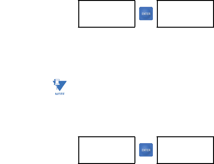
4–38 LM10 MOTOR PROTECTION SYSTEM – INSTRUCTION MANUAL
CONFIGURATION SETTINGS CHAPTER 4: FUNCTIONALITY
Entering a passcode at the Pass Code, Login screen will change the login indicated by an
asterisk at the end of the line. The default passcode is “0”. You must be logged in as
“Config” to be able to change the passcode. The green power LED will flash while logged in
as configurator. The unit will stop any run relay when in configuration mode. The LM10
must be returned to user mode before beginning normal operations.
Once the passcode is changed, the PDU will retain it in memory and will automatically
login when the CONFIG button is held/pressed upon plugging in the RJ11 connector or on
power up. This is handy when using a hand held PDU for multiple relay program changes.
4.2.11 Run Operations
PATH: Configuration ØØØØØØØØØ Run Operations
Input terminal 21 selects how the run command is controlled. If power is applied to the
relay, then the network has run control. If not the hard-wired switches control. Note that a
PDU logged in for configuration will disable run commands from both DeviceNet and hard-
wired switches.
With DeviceNet fault enabled and scanner connections not yet established, switching to
DeviceNet will cause the DeviceNet fault and stop any run condition of the LM10. Hard-
wired Stop will always have priority. If stop terminal 3 is powered, the LM10 will not run.
4.2.12 Factory Default
PATH: Configuration ØØØØØØØØØØ Factory Default
Select “Yes” to restore the factory values.
Configuration
Run Operations
Factory default
Run Operations
Run 1
Range: Run 1, Run 2, Stop
Configuration
Factory deflt
Factory Default
No
Range: No, Yes
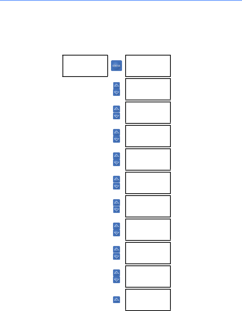
CHAPTER 4: FUNCTIONALITY STATUS VALUES
LM10 MOTOR PROTECTION SYSTEM – INSTRUCTION MANUAL 4–39
4.3 Status Values
4.3.1 Main Menu
The main menu for the status values is shown below. Press the STATUS key to access these
values.
GE LM10 1.70
Class: 10
MAC ID: 1
Baud: 500
Status Active
Ready to Run
Range: Running 1, Running 2, Ready to
Run, Fault
Status Active
Phase A: 0.0
Range: 0.0 to 3200.0 A
Status Active
Phase B: 0.0
Range: 0.0 to 3200.0 A
Status Active
Phase C: 0.0
Range: 0.0 to 3200.0 A
Status Active
GndAmps: 0.0
Range: 0.0 to 25.0 A
Status Active
VOLTs: 220
Range: 0 to 9000 V
Status Active
PowFact: 0.00
Range: 0.00 to 1.00
Status Active
KW: 0.0
Range: 0.0 to 6553.5 kW
Status Active
Avg Cur: 0.0
Range: 0.0 to 3200.0 A
Status Active
%CurUnBl: 0
Range: 0 to 250%
Status Active
Motor Hrs: 0
Range: 0 to 65535 hours in steps of 1
4–40 LM10 MOTOR PROTECTION SYSTEM – INSTRUCTION MANUAL
STATUS VALUES CHAPTER 4: FUNCTIONALITY
•Motor Hrs: The LM10 keeps a running tally of motor operation time, incremented
hourly up to 65535 hours. Upon power loss, the unit will retain any whole number of
hours already recorded. This feature is a great service tool. An example is for bearing
change; the typical maximum bearing life is 50000 hours.
This value can be reset via the Reset Run Hrs configuration setting.
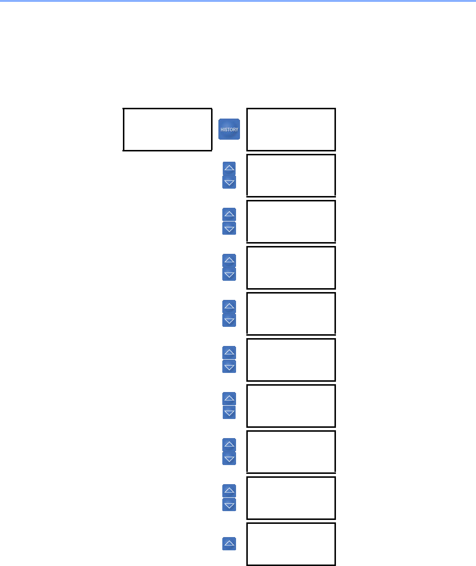
CHAPTER 4: FUNCTIONALITY HISTORY VALUES
LM10 MOTOR PROTECTION SYSTEM – INSTRUCTION MANUAL 4–41
4.4 History Values
4.4.1 Last Trip Data
Data for the last ten trips is stored in the LM10. Press the HISTORY key to access these
values. Pressing the HISTORY key multiple times scrolls between trips 1 to 10.
GE LM10 1.70
Class: 10
MAC ID: 1
Baud: 500
Last Trip #1
Overcurrent
Range: Overcurrent, Gr. Fault, Jam, Stall,
CuUnbalance, LdLoss, DevNet
Fault, Dev Stop, Voltage, Aux
Sense
Last Trip #1
Phase A: 0.0
Range: 0.0 to 3200.0 A
Last Trip #1
Phase B: 0.0
Range: 0.0 to 3200.0 A
Last Trip #1
Phase C: 0.0
Range: 0.0 to 3200.0 A
Last Trip #1
GndAmps: 0.0
Range: 0.0 to 25.0 A
Last Trip #1
VOLTs: 220
Range: 0 to 9000 V
Last Trip #1
PowFact: 1.00
Range: 0.00 to 1.00
Last Trip #1
KW: 0.0
Range: 0.0 to 6553.5 kW
Last Trip #1
Avg Cur: 0.0
Range: 0.0 to 3200.0 A
Last Trip #1
%CurUnBl: 0
Range: 0 to 250%

4–42 LM10 MOTOR PROTECTION SYSTEM – INSTRUCTION MANUAL
MOTOR START/STOP LOGIC CHAPTER 4: FUNCTIONALITY
4.5 Motor Start/Stop Logic
LM10 is designed to run in RUN1 and RUN2 mode. However, to illustrate this, only RUN1
mode is described below. The block logic diagram for RUN1 operation is shown in fig. 4-5.
Motor Status: Running 1
The relay can receive the RUN1 Start command as follows:
1. Start command through hardware RUN1 switch input
2. The RUN1 command is selected from the PDU in the configuration mode (used
for Test only)
3. Autorestart: the LM10 automatically returns to RUN1 operation after a power
loss of up to 4 seconds provided the autorestart setpoint has been enabled
and motor was running in RUN1 mode before the power loss
4. A start command is issued remotely through DeviceNet.
A PDU logged-in for configuration will disable run commands from both DeviceNet and
hardwired switches.
Motor Stop
Once the motor is in RUN1, it can be stopped as follows:
1. User asserts a hardware STOP switch Input
2. User de-asserts the RUN1 Hardware switch input (Maintained switch setting
set to ON)
3. A STOP command issued through a PDU Running Operations command (When
RUN1 command issued from PDU)
4. A stop command issued through DeviceNet
5. The relay trips on a protection function operation
6. RUN2 start command issue
7. The relay changed from USER mode to CONFIGURATION mode.
AUX Sense 1 Fault
Aux. Sense 1 fault for open contactor is detected if the main contactor status is still open
after 0.1 to 25.0 seconds (user settable) of the RUN1 O/P signal has been issued. The
contactor status is fed back to the relay through the AUX. Sense switch Input.
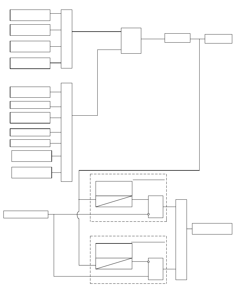
CHAPTER 4: FUNCTIONALITY MOTOR START/STOP LOGIC
LM10 MOTOR PROTECTION SYSTEM – INSTRUCTION MANUAL 4–43
AUX. Sense 1 fault detects a welded contactor when the contactor fails to open within 0.4
seconds after the RUN1 O/P signal goes off.
FIGURE 4–5: Motor RUN1 Start/Stop Logic
Autorestart
DeviceNet
RUN1 command*
OR
S
Latch
R
RUN1 O/P RUNNING#1
MOTOR STATUS
Relay O/P
DeviceNet
Stop command*
STOP PDU Command
Relay Trip OR
RUN2 Start Command
Aux.Sense1 Switch Input
Aux.Sense 1 Time
Delay
Tpkp=0.1 to 25s ec
AND
AUX.SENSE 1 FAULT
MOTOR STATUS:
Aux.Sense 1 Time
Delay
Treset= 0.4 sec AND
OR
RUN1 Switch Input
RUN1 PDU Command
STOP Switch Input
Setting: Open Contactor Logic
Welded Contacts Logic
Motor STOP Commands
Motor RUN Commands
MODE change from
USER to CONFIG
De-assert RUN1
Switch Input **
Note:
* Devicenet Commands can be issued only if the Devicenet control switch input is asserted
** The Maintained switch setting should be set to ON
4–44 LM10 MOTOR PROTECTION SYSTEM – INSTRUCTION MANUAL
MOTOR START/STOP LOGIC CHAPTER 4: FUNCTIONALITY
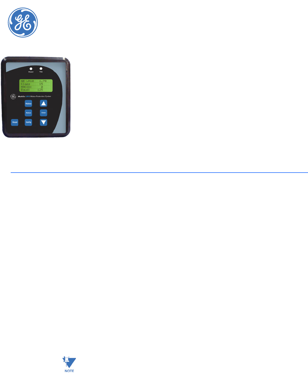
LM10 MOTOR PROTECTION SYSTEM – INSTRUCTION MANUAL 5–45
LM10 Motor Protection System
Chapter 5: Communications
GE Consumer & Industrial
Multilin
Communicatio ns
5.1 DeviceNet Operations
5.1.1 Description
The device profile is an extension of the Motor Starter Device Profile (0x16). It is a group 2
only server. It has two (2) LEDs (NET status, Module status), and hardware selectable only
MAC ID and baud rate DIP switches. The Poll function will accept a single byte of command
data and return one of three possible groups of data, according to the value of the Poll
Data Group setting.
The LM10 supports Polling, COS, and Cyclic IO data operations, and is certified as ODVA
DeviceNet CONFORMANCE TESTED™." The COS/CYC operation returns one byte of device
status described under the Assembly object, class 4, instance 54. Refer to the following
section for polling data.
5.1.2 Poll Data
The polling function accepts one byte of command data defined under the Assembly
object, class 4, instance 100. The polling input bytes can be selected from four predefined
groups of parameters with the Poll Data Group setting (refer to Other Settings on page 4–
34 for details). The list of parameters in each group is given below
Revisions 1.40 and lower do not support Poll Data Group setting. The input polling data
returns 7 bytes, The list of parameters is as given in group 1 below
5–46 LM10 MOTOR PROTECTION SYSTEM – INSTRUCTION MANUAL
DEVICENET OPERATIONS CHAPTER 5: COMMUNICATIONS
.
This data group can also be retrieved via explicit messaging to the Assembly object, class 4, instance
102, attribute 3.
This data group can also be retrieved via explicit messaging to the Assembly object, class 4, instance
103, attribute 3.
This data group can also be retrieved via explicit messaging to the Assembly object, class 4, instance
104, attribute 3.
Table 5–1: Poll Data Group 1
Bytes Data Length Name/Description Data
Format
Value
7 bytes 1 byte Motor status F21 ---
1 word Phase A current UINT × 0.1 A
1 word Phase B current UINT × 0.1 A
1 word Phase C current UINT × 0.1 A
Table 5–2: Poll Data Group 2
Bytes Data Length Name/Description Data
Format
Value
12 bytes 1 word Motor status F22 ---
1 word Cause of trip F20 ---
1 word Average phase current UINT × 0.1 A
1 word Ground current UINT × 0.1 A
1 word Current unbalance UINT %
1 word Power UINT × 0.1 kW
Table 5–3: Poll Data Group 3
Bytes Data Length Name/Description Data
Format
Value
22 bytes 1 word Motor status F22 ---
1 word Cause of trip F20 ---
1 word Phase A current UINT × 0.1 A
1 word Phase B current UINT × 0.1 A
1 word Phase C current UINT × 0.1 A
1 word Ground current UINT × 0.1 A
1 word Voltage UINT volts
1 word Power factor UINT × 0.01
1 word Power UINT × 0.1 kW
1 word Average current UINT × 0.1 A
1 word Current unbalance UINT %
Table 5–4: Poll Data Group 4
Bytes Data Length Bytes Name/Description Data
Format
Value
7 bytes 1 byte 1 Motor status F21 ---
1 word 2 (Hi), 3 (Lo) Phase A current UINT × 0.1 A
1 word 4 (Hi), 5 (Lo) Phase B current UINT × 0.1 A
1 word 6 (Hi), 7 (Lo) Phase C current UINT × 0.1 A

CHAPTER 5: COMMUNICATIONS DEVICENET OPERATIONS
LM10 MOTOR PROTECTION SYSTEM – INSTRUCTION MANUAL 5–47
The Hi and Lo bytes of the phase current A, B and C are reversed as compared to poll group 1 to make
it compatible with the format of Firmware revision 1.40 polling data.
This data group also can be retrieved via explicit messaging to the assembly object class 4, instance
105, attribute 3.
UINT = 16 bit unsigned integer.
See Data Formats on page 5–57 for details on the F20, F21, and F22 data formats.
5.1.3 Identity object
Identity Object, Class Code 1, Services:
Identity Object, Class Code 1, Attributes:
Identity Object, Class Code 1, Instance 1, Attributes:
5.1.4 Message Router
The message router (Class Code 2) object provides a messaging connection point through
which a client may address a service to any object or instance residing in the physical
device. There is no external visible interface to the message router object.
5.1.5 DeviceNet Object
DeviceNet Object, Class Code 3, Services:
DeviceNet Object, Class Code 3, Attributes:
Code Name and Description of Services Available to this Object
0x05 Reset: Reset the device to power up configuration
0x0E Get_Attribute_Single: Returns the contents of the given attribute
Attribute Access Name/Description Data Type Value
none --- --- --- ---
Attribute Access Name/Description Data Type Value
1 Get Vendor UINT 928
2 Get Device type UINT 22
3 Get Product code UINT 77
4 Get Revision (major, minor) BYTE[2] 0x013C
Code Name and Description of Services Available to this Object
0x0E Get_Attribute_Single: Returns the contents of the given attribute.
0x4B Allocate: Creates predefined M/S connections.
0x4C Release: Deletes predefined M/S connections.
Attribute Access Name/Description Data Type Value
1 Get Revision UINT 2
5–48 LM10 MOTOR PROTECTION SYSTEM – INSTRUCTION MANUAL
DEVICENET OPERATIONS CHAPTER 5: COMMUNICATIONS
DeviceNet Object, Class Code 3, Instance 1, Attributes:
5.1.6 Assembly Object
The assembly objects bind attributes of multiple objects to allow data to or from each
object to be sent or received over a single connection. There are 8 instances of the
assembly object for the device. The instance attribute is always 3 in this class.
Assembly Object, Class Code 4, Services:
Assembly Object, Class Code 4, Attributes:
Assembly Object, Class Code 4, Instance 3:
Assembly Object, Class Code 4, Instance 4:
Attribute Access Name/Description Data Type Value
2 Get Baud Rate, value 0 to 2 (125, 250, and 500 kbps) UINT from DIP
switches
5 Get Allocation information STRUCT from
service
Code Name and Description of Services Available to this Object
0x0E Get_Attribute_Single: Returns the contents of the given attribute.
0x10 Set_Attribute_Single: Sets the contents of the given attribute.
0x4C Release: Deletes predefined M/S connections.
Attribute Access Name/Description Data Type Value
none --- --- --- ---
Attribute Access Name/Description Data Type Value
3 Set Device outputs (see format and mapping below) byte see below
Data Formats for Device Outputs
Bit Position Name Value
Bit 7 Reserved ---
Bit 6 Reserved ---
Bit 5 Reserved ---
Bit 4 Reserved ---
Bit 3 Reserved ---
Bit 2 Reset ---
Bit 1 Reserved ---
Bit 0 Run 1 ---
Attribute Access Name/Description Data Type Value
3 Set Extended device outputs (see format and
mapping below) byte see below
Data Formats for Extended Device Outputs
Bit Position Name Value
Bit 7 Reserved ---
Bit 6 Reserved ---
Bit 5 Reserved ---
Bit 4 Reserved ---
CHAPTER 5: COMMUNICATIONS DEVICENET OPERATIONS
LM10 MOTOR PROTECTION SYSTEM – INSTRUCTION MANUAL 5–49
Assembly Object, Class Code 4, Instance 5:
Assembly Object, Class Code 4, Instance 52:
Assembly Object, Class Code 4, Instance 53:
Bit 3 Reserved ---
Bit 2 Reserved ---
Bit 1 Run 2 ---
Bit 0 Run 1 ---
Attribute Access Name/Description Data Type Value
3 Set Extended device outputs (see format and
mapping below) byte see below
Data Formats for Extended Device Outputs
Bit Position Name Value
Bit 7 Reserved ---
Bit 6 Reserved ---
Bit 5 Reserved ---
Bit 4 Reserved ---
Bit 3 Reserved ---
Bit 2 Reset ---
Bit 1 Run 2 ---
Bit 0 Run 1 ---
Attribute Access Name/Description Data type Value
3 Get Device inputs (see format/mapping below) byte see below
Data Formats for Device Inputs
Bit Position Name Value
Bit 7 Reserved ---
Bit 6 Reserved ---
Bit 5 Reserved ---
Bit 4 Reserved ---
Bit 3 Reserved ---
Bit 2 Running 1 ---
Bit 1 Reserved ---
Bit 0 Fault ---
Attribute Access Name/Description Data Type Value
3 Get Device inputs (see format/mapping below) byte see below
Data Formats for Device Inputs
Bit Position Name Value
Bit 7 Reserved ---
Bit 6 Reserved ---
Bit 5 Control from Net ---
Data Formats for Extended Device Outputs
Bit Position Name Value
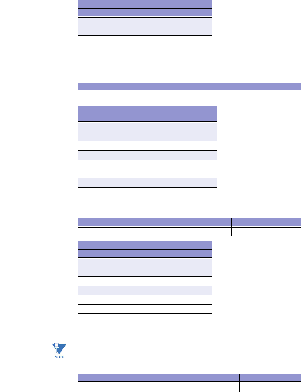
5–50 LM10 MOTOR PROTECTION SYSTEM – INSTRUCTION MANUAL
DEVICENET OPERATIONS CHAPTER 5: COMMUNICATIONS
Assembly Object, Class Code 4, Instance 54. Use this object for data received by the master
from the slave device.
Assembly Object, Class Code 4, Instance 100. Use this object for data transmitted from the
master to the slave device.
* If the LM10 has been put into Admin mode via the PDU display and this bit is set to '1', the
PDU display will continue to appear to be in Config mode but no settings will be able to be
changed. The LM10 will now be in 'User' mode.
Assembly Object, Class Code 4, Instance 101:
Bit 4 Reserved ---
Bit 3 Reserved ---
Bit 2 Running 1 ---
Bit 1 Warning ---
Bit 0 Fault ---
Attribute Access Name/Description Data Type Value
3 Get Device inputs (see format/mapping below) byte see below
Data Formats for Device Inputs
Bit Position Name Value
Bit 7 Aux Sense 2 unput status ---
Bit 6 Aux Sense 1 unput status ---
Bit 5 Control from Devicenet ---
Bit 4 Reserved ---
Bit 3 Running 2 ---
Bit 2 Running 1 ---
Bit 1 Reserved ---
Bit 0 Fault ---
Attribute Access Name/Description Data Type Value
3 Set Control (see format below) byte see below
Data Formats for Device Inputs
Bit Position Name Value
Bit 7 Reserved ---
Bit 6 Reserved ---
Bit 5 Security to Min* ---
Bit 4 Reserved ---
Bit 3 Stop ---
Bit 2 Fault Reset ---
Bit 1 Run 2 ---
Bit 0 Run 1 ---
Data Formats for Device Inputs
Bit Position Name Value
Attribute Access Name/Description Data Type Value
3 Get Fault and status (see format below) byte see below
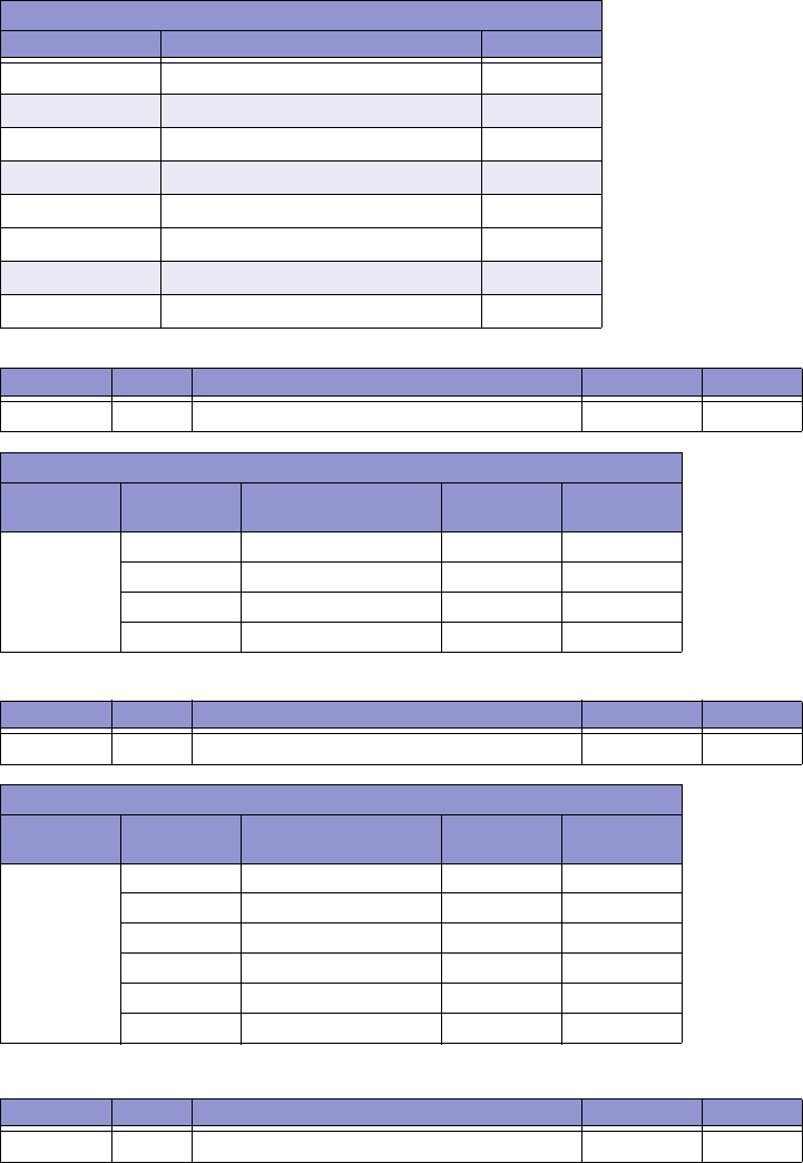
CHAPTER 5: COMMUNICATIONS DEVICENET OPERATIONS
LM10 MOTOR PROTECTION SYSTEM – INSTRUCTION MANUAL 5–51
Assembly Object, Class Code 4, Instance 102
Assembly Object, Class Code 4, Instance 103
Assembly Object, Class Code 4, Instance 104
Data Formats for Device Inputs
Bit Position Name Value
Bit 7 DeviceNet Stop Issued Last ---
Bit 6 Reserved ---
Bit 5 DeviceNet Control ---
Bit 4 Reserved ---
Bit 3 Running 2 ---
Bit 2 Running 1 ---
Bit 1 Reserved ---
Bit 0 Fault ---
Attribute Access Name/Description Data Type Value
3 Get Poll Data Group 1 see below see below
Data Formats for Device Inputs
Bytes Data Length Name/Description Data
Format
Value
7 bytes 1 byte Motor status F21 ---
1 word Phase A current UINT × 0.1 A
1 word Phase B current UINT × 0.1 A
1 word Phase C current UINT × 0.1 A
Attribute Access Name/Description Data Type Value
3 Get Poll Data Group 2 see below see below
Data Formats for Device Inputs
Bytes Data Length Name/Description Data
Format
Value
12 bytes 1 word Motor status F22 ---
1 word Cause of trip F20 ---
1 word Average phase current UINT × 0.1 A
1 word Ground current UINT × 0.1 A
1 word Current unbalance UINT %
1 word Power UINT × 0.1 kW
Attribute Access Name/Description Data Type Value
3 Get Poll Data Group 3 see below see below
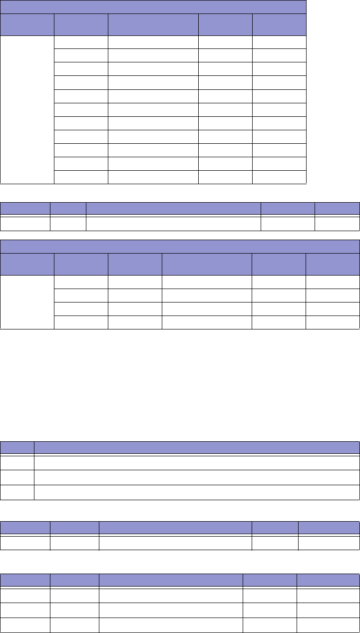
5–52 LM10 MOTOR PROTECTION SYSTEM – INSTRUCTION MANUAL
DEVICENET OPERATIONS CHAPTER 5: COMMUNICATIONS
Assembly Object, Class Code 4, Instance 105
5.1.7 Connection Object
The connection objects manage the characteristics of each communication connection.
There are three instances of the connection object in the device. Explicit connection
(< 50ms response), input/output connection poll, (< 10ms response), and input/output
connection Cos/Cyc (< 10ms response)
Connection Object, Class Code 5, Services:
Connection Object, Class Code 5, Attributes:
Connection Object, Class Code 5, Instance 1 (explicit message connection):
Data formats for device inputs
Bytes Data Length Name/Description Data
Format
Value
22 bytes 1 word Motor status F22 ---
1 word Cause of trip F20 ---
1 word Phase A current UINT × 0.1 A
1 word Phase B current UINT × 0.1 A
1 word Phase C current UINT × 0.1 A
1 word Ground current UINT × 0.1 A
1 word Voltage UINT volts
1 word Power factor UINT × 0.01
1 word Power UINT × 0.1 kW
1 word Average current UINT × 0.1 A
1 word Current unbalance UINT %
Attribute Access Name/Description Data Type Value
3 Get Poll Data Group 4 see below see below
Data Formats for Device Inputs
Bytes Data Length Bytes Name/Description Data
Format
Value
7 bytes 1 byte 1 Motor status F21 ---
1 word 2 (Hi), 3 (Lo) Phase A current UINT × 0.1 A
1 word 4 (Hi), 5 (Lo) Phase B current UINT × 0.1 A
1 word 6 (Hi), 7 (Lo) Phase C current UINT × 0.1 A
Code Name and Description of Services Available to this Object
0x05 Reset the connection - restart timer
0x0E Get_Attribute_Single: Returns the contents of the given attribute.
0x10 Set_Attribute_Single: Sets the contents of the given attribute
Attribute Access Name/Description Data Value
none --- --- --- ---
Attribute Access Name/Description Data Type Value
1GetState BYTE0x03
2 Get Instance_type BYTE 0x00, 0x01
3 Get Export class trigger BYTE 0x83

CHAPTER 5: COMMUNICATIONS DEVICENET OPERATIONS
LM10 MOTOR PROTECTION SYSTEM – INSTRUCTION MANUAL 5–53
Connection Object, Class Code 5, Instance 2 (polled input/output connection):
Connection Object, Class Code 5, Instance 4 (COS/Cyc input/output connection):
4 Get Produced connection ID UINT MAC ID
5 Get Consumed connection ID UINT MAC ID
6 Get Initial comm. characteristics UINT 0x21
7 Get Produced connection size UINT 0x12
8 Get Consumed connection size UINT 0x12
9 Get/Set Expected package rate UINT 0x00
12 Get/Set Watchdog timeout action UINT 0x00
13 Get Produced path length UINT 0x0000
14 Get Produced path BYTE [6] <null>
15 Get Consumed path length UINT 0x0000
16 Get Consumed path BYTE [6] <null>
17 Get Production inhibit timer UINT 0x0000
Attribute Access Name/Description Data type Value
1GetState BYTE0x03
2GetInstance_type BYTE0x01
3 Get Export class trigger BYTE 0x80, 0x82
4 Get Produced connection ID UINT MAC ID
5 Get Consumed connection ID UINT MAC ID
6 Get Initial comm. characteristics UINT 0x01, 0xF1
7 Get Produced connection size UINT 0x01
8 Get Consumed connection size UINT 0x01
9 Get/Set Expected package rate UINT 0x00
12 Get/Set Watchdog timeout action UINT 0x00
13 Get Produced path length UINT 0x0006
14 Get Produced path BYTE [6] *
*The Produced path will vary depending on the setting for Poll Data Group:
Poll Group 1: 0x20, 0x04, 0x24, 0x66, 0x30, 0x03 (Class 4, Inst. 102, Attr. 3)
Poll Group 2: 0x20, 0x04, 0x24, 0x67, 0x30, 0x03 (Class 4, Inst. 103, Attr. 3)
Poll Group 3: 0x20, 0x04, 0x24, 0x68, 0x30, 0x03 (Class 4, Inst. 104, Attr. 3)
Poll Group 4: 0x20, 0x04, 0x24, 0x69, 0x30, 0x03 (Class 4, Inst. 105, Attr. 3)
15 Get Consumed path length UINT 0x0006
16 Get Consumed path BYTE [6] 0x20, 0x04,
0x24, 0x64,
0x30, 0x03
17 Get Production inhibit timer UINT 0x0000
Attribute Access Name/Description Data Type Value
1GetState BYTE0x03
2GetInstance_type BYTE0x01
3 Get Export class trigger BYTE 0x00, 0x02,
0x10, 0x12
4 Get Produced connection ID UINT MAC ID
5 Get Consumed connection ID UINT MAC ID
6 Get Initial comm. characteristics UINT 0x01
Attribute Access Name/Description Data Type Value
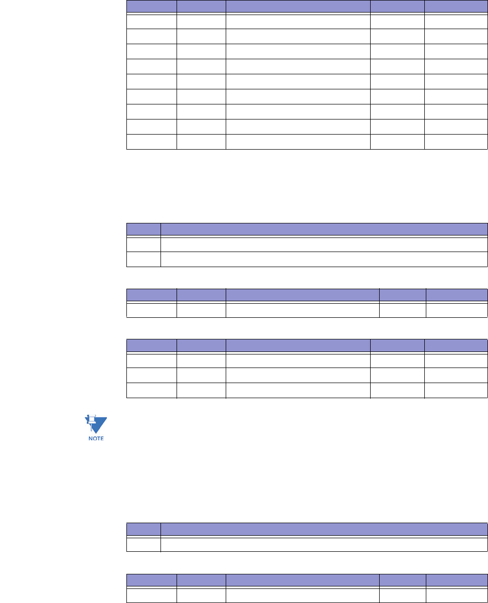
5–54 LM10 MOTOR PROTECTION SYSTEM – INSTRUCTION MANUAL
DEVICENET OPERATIONS CHAPTER 5: COMMUNICATIONS
5.1.8 ACK Handler Object
The 'acknowledge handler object' manages the reception of message acknowledgments.
ACK handler Object, Class Code 0x2B, Services:
ACK handler Object, Class Code 0x2B, Attributes:
ACK handler Object, Class Code 0x2B, Instance 1:
USINT = 8-bit unsigned integer
UINT = 16-bit unsigned integer
5.1.9 Overload Object
The overload object allows the getting of the active parameter values.
Overload Object, Class Code 0x2C, Services:
Overload Object, Class Code 0x2C, Attributes:
7 Get Produced connection size UINT 0x0008
8 Get Consumed connection size UINT 0x0000
9 Get/Set Expected package rate UINT 0x00
12 Get/Set Watchdog timeout action UINT 0x00
13 Get Produced path length UINT 0x0006
14 Get Produced path BYTE [6] <null>
15 Get Consumed path length UINT 0x0004
16 Get Consumed path BYTE [6] <null>
17 Get Production inhibit timer UINT 0x0000
Attribute Access Name/Description Data Type Value
Code Name and Description of Services Available to this Object
0x0E Get_Attribute_Single: Returns the contents of the given attribute.
0x10 Set_Attribute_Single: Sets the contents of the given attribute
Attribute Access Name/Description Data Value
none --- --- --- ---
Attribute Access Name/Description Data Type Value
1 Get/Set Acknowledge Timer UINT 16
2 Get/Set Retry Limit USINT 1
3 Get COS Connection Instance UINT 4
Code Name and Description of Services Available to this Object
0x0E Get_Attribute_Single: Returns the contents of the given attribute.
Attribute Access Name/Description Data Value
none --- --- --- ---
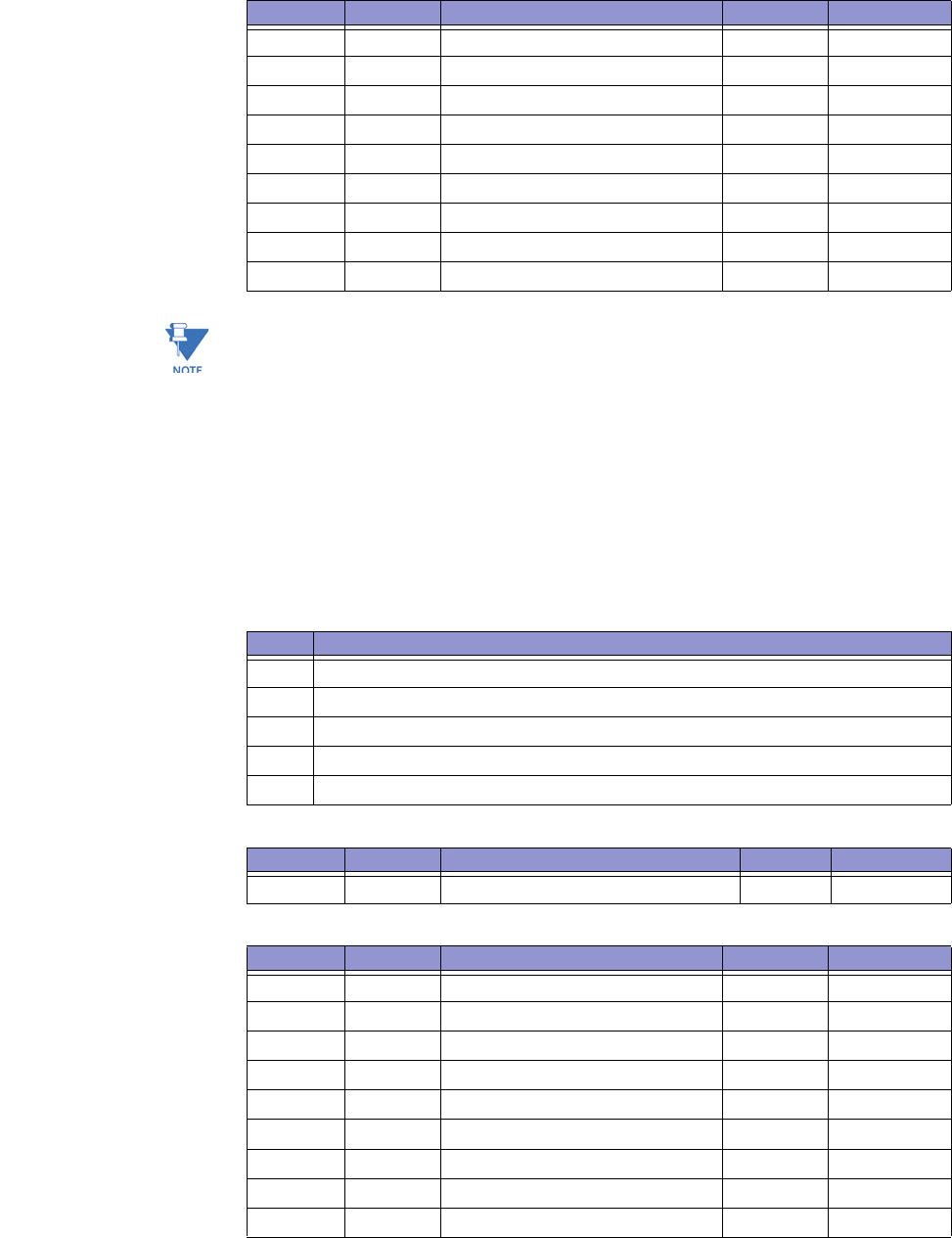
CHAPTER 5: COMMUNICATIONS DEVICENET OPERATIONS
LM10 MOTOR PROTECTION SYSTEM – INSTRUCTION MANUAL 5–55
Overload Object, Class Code 0x2C, Instance 1:
UINT = 16-bit unsigned integer
5.1.10 Extension Object
The extension handler object manages the access to settings and parameters not
provided for in the standard device type 0x16. It has one instance. It uses instance
attributes for all of its functions and data.
Data present in class 0x64 is accessed via explicit messaging.
Extension object, class code 0x64, Services:
Extension object, Class Code 0x64, attributes:
Extension object, class code 0x64, instance 1:
Attribute Access Name/Description Data Type Value
3 Get FLA INT ---
4 Get Trip Class USINT ---
5 Get Average Current INT ---
6 Get Phase Unbalance USINT ---
8 Get Current Phase A INT ---
9 Get Current Phase B INT ---
10 Get Current Phase C INT ---
11 Get Ground Current INT ---
12 Get Current Scale (fixed at 100 mA) SINT 1
Code Name and Description of Services Available to this Object
0x0E Get_Attribute_Single: Returns the contents of the given attribute.
0x10 Set_Attribute_Single: Sets the contents of the given attribute
0x32 History, read data from active and history records
0x33 Login, user level
0x4A Call, process function operation
Attribute Access Name/Description Data Value
none --- --- --- ---
Attribute Access Name/Description Data Type Value
0x00 Get Series and model BYTE [2]
0x01 Get Version and revision BYTE [2]
0x02 Get/set User setting, FLA, Run 1, (word) F1 ×0.1 A
0x03 Get/set User setting, FLA, Run 2, (word) F1 ×0.1 A
0x04 Get/set User setting, Run 1 ground fault F2 Trip, Time
0x05 Get/set User setting, Run 2 ground fault F2 Trip, Time
0x06 Get/set User setting, Run 1, jam F3 Trip, Time
0x07 Get/set User setting, Run 2, jam F3 Trip, Time
0x08 Get/set User setting, Run 1, stall F4 Trip, Time

5–56 LM10 MOTOR PROTECTION SYSTEM – INSTRUCTION MANUAL
DEVICENET OPERATIONS CHAPTER 5: COMMUNICATIONS
The data type format codes for class code 0x64, instance 1 are shown below.
0x09 Get/set User setting, Run 2, stall F4 Trip, Time
0x0A Get/set User setting, Run 1, unbalance F5 Trip, Time
0x0B Get/set User setting, Run 2, unbalance F5 Trip, Time
0x0C Get/set User setting, Run 1, load loss F6 Trip, Time
0x0D Get/set User setting, Run 2, load loss F6 Trip, Time
0x0E Get/set User setting, power transformers F7 0 to 11
0x0F Get/set User setting, current transformers F8 1 to 15
0x10 Get/set User setting, auxiliary sense 1 timer F9 0.1 × (0 to 250)
0x11 Get/set User setting, auxiliary sense 2 timer F10 0.1 × (0 to 250)
0x12 Get/set User setting, auxiliary relay flags F11 16 bits
0x15 Get Motor run time hours UINT Hours
0x1A Get/set Configure passcode UINT Code (0)
0x24 Get/set User setting, motor type F12 Type 0 to 5
0x25 Get/set User setting, loops through CT F13 1 to 4
0x26 Get/set Flags (Mrun, AutoRestart, O/V Volt
Enable, DNFault, 50 Hz) F14 16 bits
0x2E Call Reset LM10*N/A ---
0x1C Call Reset factory default user settings N/A ---
0x2F Get Trip class F17 ---
0x30 Get MAC ID F18 ---
0x31 Get DeviceNet baud rate F19 ---
0x34 Get Input switch status F25 16 bits
0x38 Get Remaining cool-down period F26 16 bits
0x39 Get/set Poll data group F15 1 to 4
0x3A Get/set Run1-Run2 time delay F16 0 to 600 sec.
0x3B Get/set Run2-Run1 time delay2F16 0 to 600 sec.
0x40 History Status (send data byte 0 for current, 1
to 10 for history) F24 ---
0x41 History Phase A current F23 ×0.1 A
0x42 History Phase B current F23 ×0.1 A
0x43 History Phase C current F23 ×0.1 A
0x44 History Ground current F23 ×0.1 A
0x45 History Voltage UINT volts
0x46 History Power factor UINT percent
0x47 History Watts F23 0.1 kW
0x48 History Operating current F23 ×0.1 A
0x49 History Current unbalance UINT percent
0x50 Login User --- ---
0x51 Login Configuration UINT Passcode
0x52 Login Calibration UINT Passcode
*This call function has the same result as pressing the Reset key on the PDU display
Applies to revisions 1.50 and higher
Attribute Access Name/Description Data Type Value
CHAPTER 5: COMMUNICATIONS DEVICENET OPERATIONS
LM10 MOTOR PROTECTION SYSTEM – INSTRUCTION MANUAL 5–57
5.1.11 Data Formats
F1: Full Load Current (16-bit unsigned integer)
Range: 0x000C to 0x1F40 (i.e. 1.2 to 800.0 A)
Multiplying factor: 0.1
Example: 123.4 stored as 1234
F2: Ground Fault
Format: two bytes in format 0xHHLL, where LL is the pickup level and HH is the time delay
Byte LL range: 0x00, 0x02 to 0x64 (i.e. 0.4 to 20.0 A), where 0x00 is disabled
Byte LL multiplying factor: 0.2 (i.e. actual = byte LL in decimal × 0.2 amps)
Byte HH range: 0x00 to 0x19 (i.e. 0 to 2.5 seconds)
Byte HH multiplying factor: 0.1 (i.e. actual = byte HH in decimal × 0.1 seconds)
F3: Jam
Format: two bytes in format 0xHHLL, where LL is the pickup level and HH is the time delay
Byte LL range: 0x00, 0x64 to 0xFA (i.e. 100 to 250%), where 0x00 is disabled
Byte HH range: 0x00 to 0xC8 (i.e. 0 to 1000 seconds)
Byte HH multiplying factor: 5 (i.e. actual = byte HH in decimal × 5 seconds)
F4: Stall
Format: two bytes in format 0xHHLL, where LL is the pickup level and HH is the time delay
Byte LL range: 0x00, 0x42 to 0x78 (i.e. 330 to 600%), where 0x00 is disabled
Byte LL multiplying factor: 5 (i.e. actual = byte LL in decimal × 5%)
Byte HH range: 0x00 to 0x3C (i.e. 0 to 30.0 seconds)
Byte HH multiplying factor: 0.5 (i.e. actual = byte HH in decimal × 0.5 seconds)
F5: Current Unbalance
Format: two bytes in format 0xHHLL, where LL is the pickup level and HH is the time delay
Byte LL range: 0x00, 0x02 to 0x19 (i.e. 2 to 25%), where 0x00 is disabled
Byte HH range: 0x00 to 0xFF (i.e. 0 to 255 seconds)
F6: Load Loss
Format: two bytes in format 0xHHLL, where LL is the pickup level and HH is the time delay
Byte LL range: 0x00, 0x0F to 0x64 (i.e. 15 to 100%), where 0x00 is disabled
Byte HH range: 0x00 to 0xFF (i.e. 0 to 255 seconds)
F7: Power Transformer
Format: two bytes in format 0xHHLL, where LL is the PT ratio and HH is reserved
Byte LL enumeration:
F8: Current Transformer
Format: two bytes in format 0xHHLL, where LL is the CT ratio and HH is reserved
Byte LL enumeration:
Value PT Ratio Value PT Ratio
0 200:120 6 3300:120
1 240:120 7 4200:120
2 480:120 8 4800:120
3 600:120 9 5400:120
4 2400:120 10 6000:120
5 3000:120 11 7200:120
Value CT Ratio Value CT Ratio
1 27 A sensor pack 9 250:5
5–58 LM10 MOTOR PROTECTION SYSTEM – INSTRUCTION MANUAL
DEVICENET OPERATIONS CHAPTER 5: COMMUNICATIONS
F9: Auxiliary Sense 1 / Run1-Run2 Time Delays
Format: two bytes in format 0xHHLL, where LL is the auxiliary sense 1 time delay and HH is
the Run1-Run2 time delay (Run1-Run2 time delay for revisions 1.40 and lower only)
Byte LL range: 0x00 to 0xFA (i.e. 0.0 to 25.0 seconds), where 0x00 is disabled
Byte LL multiplying factor: 0.1 (i.e. actual = byte LL in decimal × 0.1 seconds)
Byte HH range: 0x00 to 0xB4 (i.e. 0 to 180 seconds)
F10: Auxiliary Sense 2 / Run2-Run1 Time Delays
Format: two bytes in format 0xHHLL, where LL is the auxiliary sense 2 time delay and HH is
the Run2-Run1 time delay (Run2-Run1 time delay for revisions 1.40 and lower only)
Byte LL range: 0x00 to 0xFA (i.e. 0.0 to 25.0 seconds), where 0x00 is disabled
Byte LL multiplying factor: 0.1 (i.e. actual = byte LL in decimal × 0.1 seconds)
Byte HH range: 0x00 to 0xB4 (i.e. 0 to 180 seconds)
F11: Auxiliary Relay Faults (16-bit bitmask)
F12: Starter Type
Format: two bytes in format 0xHHLL, where LL is the motor type and HH is reserved
Byte LL enumeration:
F13: CT Turns
Format: two bytes in format 0xHHLL, where LL is the number of CT turns and HH is
reserved
2 90 A sensor pack 10 300:5
3 75:5 11 400:5
4 100:5 12 500:5
5 120:5 13 600:5
6 150:5 14 700:5
7 200:5 15 800:5
8 225:5
Bitmask Fault
---- ---- ---- ---1 Overcurrent
---- ---- ---- --1- Reserved
---- ---- ---- -1-- Jam
---- ---- ---- 1--- Stall
---- ---- ---1 ---- Current unbalance
---- ---- --1- ---- Aux sense
---- ---- -1-- ---- Load loss
---- ---- 1--- ---- Reserved
---- ---1 ---- ---- Reserved
---- --1- ---- ---- DeviceNet
---- -1-- ---- ---- Voltage range
Value Starter Type
0 FVNR (full voltage non-reversing)
1 FVR (full voltage reversing)
2 RV (reversing)
3 2S1W (two-speed one winding; Run-2, 4:1 ratio of Run-1)
4 2S2W (two-speed two winding; Run-2, 2:1 ratio of Run-1)
5Custom
Value CT Ratio Value CT Ratio

CHAPTER 5: COMMUNICATIONS DEVICENET OPERATIONS
LM10 MOTOR PROTECTION SYSTEM – INSTRUCTION MANUAL 5–59
Byte LL range: 0x01 to 0x04 (i.e. 1 to 4 turns)
F14: Other Settings (16-bit Bitmask)
F15: Poll Data Group (enumeration; 16-bit unsigned integer)
F16: Run1-Run2 and Run2-Run1 Time Delay (16-bit unsigned integer)
Range: 0x0000 to 0x0258 (i.e. 0 to 600 seconds)
F17: Trip Class
Format: two bytes in format 0xHHLL, where LL is the trip class and HH is reserved
Byte LL enumeration:
F18: MAC ID
Format: two bytes in format 0xHHLL, where LL is the MAC ID and HH is reserved
Byte LL range: 0x00 to 0x3F (i.e. 0 to 63)
F19: Baud Rate (enumeration: 16-bit unsigned integer)
Range: 0x007D, 0x00FA, 0x01F4 (i.e. 125, 250, and 500 kbps)
F20: Cause of Trip (16-bit bitmask)
Bitmask Other Settings
---- ---- ---- ---1 Maintained input switch
---- ---- ---- --1- Auto restart
---- ---- ---- -1-- Under/overvoltage enable
---- ---- ---- 1--- DeviceNet fault
---- ---- ---1 ---- Reserved
---- ---- --1- ---- Reserved
---- ---- -1-- ---- Reserved
---- ---- 1--- ---- Reserved
---- ---1 ---- ---- 50 Hz system on
Value Poll Group
1 Poll 1 (7 bytes)
2 Poll 2 (12 bytes)
3 Poll 3 (22 bytes)
4 Poll 4 (7 bytes)
Value Trip Class
0A Trip class 10
0F Trip class 15
14 Trip class 20
1E Trip class 30
Bitmask Cause of Trip
---- ---- ---- ---1 No trip
---- ---- ---- --1- Overcurrent
---- ---- ---- -1-- Ground fault
---- ---- ---- 1--- Jam
---- ---- ---1 ---- Stall
---- ---- --1- ---- Current unbalance
---- ---- -1-- ---- Aux sense
---- ---- 1--- ---- Load loss
---- ---1 ---- ---- Reserved
---- --1- ---- ---- DeviceNet stop

5–60 LM10 MOTOR PROTECTION SYSTEM – INSTRUCTION MANUAL
DEVICENET OPERATIONS CHAPTER 5: COMMUNICATIONS
F21: Motor Status (8-bit Bitmask)
F22: Motor Status (16-bit bitmask)
F23: 16-bit Unsigned Integer
Multiplying factor: 0.1
Example: 123.4 stored as 1234
F24: Status Word (16-bit bitmask)
The first, second, and fourth 4-bit sections of the 16-bit status word are bitmasks that
indicate the following:
---- -1-- ---- ---- DeviceNet fault
---- 1--- ---- ---- Reserved
---1 ---- ---- ---- Under/overvoltage
Bitmask Status
---- ---1 Fault
---- --1- Reserved
---- -1-- Running 1
---- 1--- Running 2
---1 ---- Reserved
--1- ---- Control from DeviceNet
-1-- ---- Aux Sense 1 input status
1--- ---- Aux Sense 2 input status
Bitmask Other Settings
---- ---- ---- ---1 Fault
---- ---- ---- --1- Reserved
---- ---- ---- -1-- Running 1
---- ---- ---- 1--- Running 2
---- ---- ---1 ---- Reserved
---- ---- --1- ---- Control from DeviceNet
---- ---- -1-- ---- Aux Sense 1 input status
---- ---- 1--- ---- Aux Sense 2 input status
---- ---1 ---- ---- Stop switch input status
---- --1- ---- ---- Reset switch input status 2
---- -1--- ---- ---- Run 1 switch input status
---- 1--- ---- ---- Run 2 switch input status
Bitmask Status
---- ---- ---- ---1 Fault (cause indicated by 2nd byte, see below)
---- ---- ---- --1- Warning
---- ---- ---- -1-- 1 is running
---- ---- ---- 1--- 2 is running
---- ---- ---1 ---- Reserved
---- ---- --1- ---- DeviceNet control
---- ---- -1-- ---- DeviceNet active
---- ---- 1--- ---- DeviceNet issued last stop
---1 ---- ---- ---- Reserved
--1- ---- ---- ---- Reserved
-1-- ---- ---- ---- Login > user
Bitmask Cause of Trip

CHAPTER 5: COMMUNICATIONS DEVICENET OPERATIONS
LM10 MOTOR PROTECTION SYSTEM – INSTRUCTION MANUAL 5–61
The third 4-bit section is an enumeration which indicates the cause of the fault.
F25: Input Switch Status (16-bit value; use only lower byte)
Format: two bytes in format 0xHHLL, where LL is the Switch Input status and HH is
Reserved.
F26: Remaining Cool-Down Period - Format: two bytes in format 0xHHLL, where LL is the
Remaining Cool-Down Period and HH is Reserved. Byte LL Range: 0 to 99
5.1.12 Special Application
The LM10 Motor Protection System has a DeviceNet interface. The DEVICENET CONTROL
input will set the RUN control to be operated using the DeviceNet interface. For this
application we will assume this input to be tied active. This will disable any hard-wired
120 V AC RUN inputs from being accepted as a command to the LM10. The LM10 can read
the state of these inputs through the DeviceNet protocol.
With the use of this read request the DeviceNet scanner (PLC or Master) can check the
state of the local switches. After evaluating that all conditions of the system are
appropriate the RUN command can be sent to the LM10 through the DeviceNet link. The
RESET and STOP inputs do remain active at all times. The STOP input will command the
LM10 to stop the motor even though the DeviceNet is the controlling input. The DeviceNet
scanner would be able to detect this stop by monitoring the LM10 status. The status word
can be polled or setup as a Cos/Cyclic.
Auxiliary sense inputs are also activated by a 120 V AC signal. If the end user desires, he
may use these inputs for an alternate purpose if the Auxiliary Sense capability of the LM10
is disabled. The data is part of the same word as the RUN inputs.
1--- ---- ---- ---- Motor hot at time of fault
Value Bitmask Status
0 ---- 0000 ---- ---- None
1 ---- 0001 ---- ---- Overcurrent
2 ---- 0010 ---- ---- Ground fault
3 ---- 0011 ---- ---- Jam lock
4 ---- 0100 ---- ---- Stall aux
5 ---- 0101 ---- ---- Current unbalance
6 ---- 0110---- ---- Aux sense
7 ---- 0111 ---- ---- Load loss
8---- 1000 ---- ---- Reserved
9---- 1001 ---- ---- Reserved
10 ---- 1010 ---- ---- DeviceNet
11 ---- 1011 ---- ---- Operating voltage
Bitmask (LL) Status
---- ---1 Stop switch input switch
---- --1- Reset switch input switch
---- -1-- Run1 switch input switch
---- 1--- Run2 switch input switch
---1 ---- Auxsense1 switch input switch
--1- ---- Auxsense2 switch input switch
Bitmask Status

5–62 LM10 MOTOR PROTECTION SYSTEM – INSTRUCTION MANUAL
DEVICENET OPERATIONS CHAPTER 5: COMMUNICATIONS
This data was initially setup for development purposes. An explicit message through the
custom class 100(0x64) is the only way to access this data. The DeviceNet message to read
this data is: service 0x0e, class 0x64, instance 1, and attribute 0x34. The response will be a
16-bit word with MACID switches in the high byte and AC switch input bits in the low byte.
• Sent by scanner: CANID, MACID, 0x0E, 0x64, 0x01, 0x34
• Response from the LM10: CANID, MACID, 0x8E, LBY, HBY
The format of this data follows F25: Input Switch Status. The high byte (HBY) is not used in
this application. The low byte (LBY) is the input data we are looking for. The seven hard
wired inputs map to bits 0 to 6 as DeviceNet Control, AxSn2, AxSn1, RUN2, RUN1, Reset,
Stop. To watch for RUN1 one would test for bit 2 being on. EX: LBY and 0x04 is not equal to
0x00.
Do not switch out of DeviceNet Control while the motor is running. In such a case the LM10
will issue a Stop command under the assumption that the network is down.

CHAPTER 5: COMMUNICATIONS SERIAL PORT
LM10 MOTOR PROTECTION SYSTEM – INSTRUCTION MANUAL 5–63
5.2 Serial Port
5.2.1 Description
This is a standard RS232 port to handle the serial messages. It has a fixed port settings of
19200, 8, N, 1. The PDU uses this port. The protocol for request and response of data is a
fixed 8-byte packet. It will always start with SOH and end with a simple checksum (~sum +
1). The packets will include all the functionality found in the DeviceNet Extension object.
The data is in ‘big endian’ format here (big end first: MSB-LSB). The packet is outlined below:
Bit Position Name
Bit 7 SOH
Bit 6 Service
Bit 5 Attribute
Bit 4 Data 3
Bit 3 Data 2
Bit 2 Data 1
Bit 1 Data 0
Bit 0 Checksum
5–64 LM10 MOTOR PROTECTION SYSTEM – INSTRUCTION MANUAL
SERIAL PORT CHAPTER 5: COMMUNICATIONS
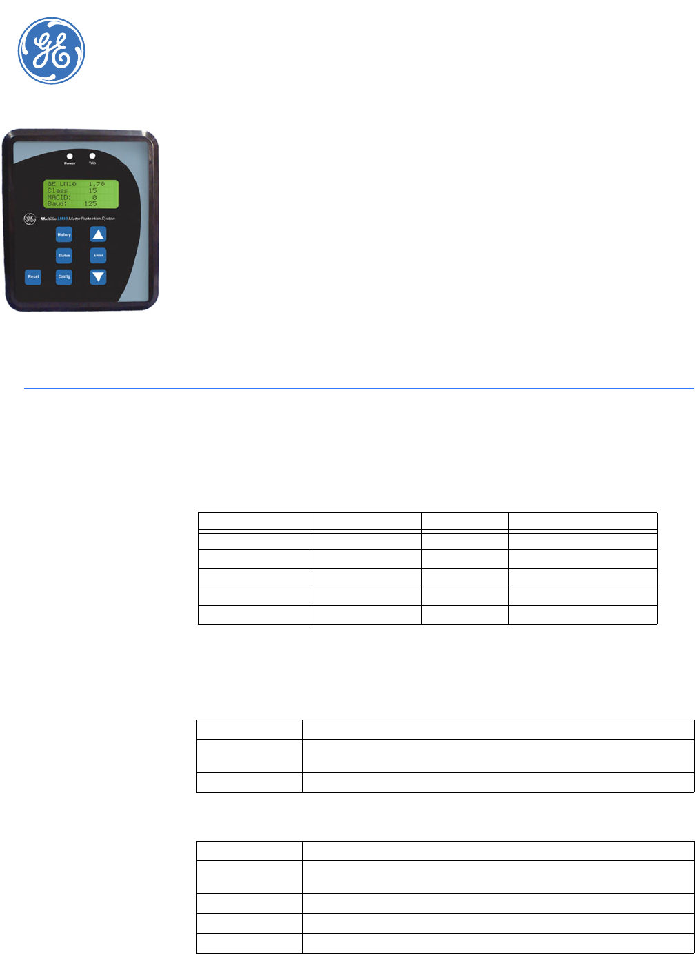
LM10 MOTOR PROTECTION SYSTEM – INSTRUCTION MANUAL 6–65
LM10 Motor Protection System
Chapter 6: Miscellaneous
GE Consumer & Industrial
Multilin
Miscellaneou s
6.1 Revision History
6.1.1 Release Dates
6.1.2 Changes to the Manual
l
l
Table 6–1: Release Dates
Manual GE Part Number LM10 Revision Release Date
GEK-106642 1601-0165-A1 1.37 25 October 2004
GEK-106642A 1601-0165-A2 1.40 17 December 2004
GEK-106642B 1601-0165-A3 1.50 22 February 2006
GEK-106642C 1601-0165-A4 1.60 19 January 2007
GEK-106642D 1601-0165-A5 1.70 14 August 2007
Table 6–2: Changes to Manual Since Release A4
Section Number Revision
Update Manual to A5 and Firmware (and Firmware references) to
v1.70
1.5.4 Wording change... Added note.
Table 6–3: Changes to Manual Since Release A4
Section Number Revision
Update Manual to A5 and Firmware (and Firmware references) to
v1.70
1.3.3 Change revision in the images of the product from 1.60 to 1.0
1.5.2 Change Phase Current range
1.5.2 Change Average Current range

6–66 LM10 MOTOR PROTECTION SYSTEM – INSTRUCTION MANUAL
REVISION HISTORY CHAPTER 6: MISCELLANEOUS
3.2.4 Move section to 5.1.10
5.1.2 Add Poll Data 4
5.1.6 Add Assembly Object, Class Code 4, Instance 105 (Poll Data Group 4)
5.1.8 Control Supervisor Object - Delete Section
5.1.11 Change format code F15 to include Poll Data Group 4
5.1.11 Add bit locations to format codes F21 and F22
Table 6–4: Changes to Manual Since Release A3
Section Number Revision
Update Manual to A4 and Firmware (and Firmware references) to
v1.60
1.3.3 Change revision in the images of the product from 1.50 to 1.60
1.4.1 Table 1-1 - LM10 Order Code text changed
1.5.1 Change Ground Fault, Jam, Stall, Current Unbalance, Load Loss
specifications
3.2.3 Change text "The unit has three passcode levels..."
4.2.1 Changes to Ground Fault Level, Stall Level, Load Loss Level,
Undervoltage, Overvoltage
4.2.6 Changes to Ground Setup, Stall Setup
4.2.6 Change to equation 4-3
5.1.6 Assembly Object, Class Code 4, Instance 100
"Security to Min" in Control Byte clarified. Note added.
5.1.6 Change to Assembly Object, Class Code 4, Instance 101, Attribute
3,Bit 6
5.1.11 Change to format code F20
5.1.11 Change to format code F24
5.1.2 Change to Identity Object, Class Code 1, Instance 1, Attributes
5.1.11 Add attribute (Attribute: 0x34)
5.1.11 New format code: F25 - Input Switch Status
5.1.11 Add attribute (Attribute: 0x38)
5.1.11 New format code: F26 - Remaining Cool-Down Period
5.1.6 Change to Assembly Object, Class Code 4, Instance 52
5.1.11 Change text description for attribute 0x26
5.1.11 Correction to F14 format
5.1.7 Changes to Connection Object, Class Code 5, Instance 2 (polled...)
5.1.11 Change the ranges for the delays to match range shown in Chapter 4
5.1.5 Add three additional tables before the "Connection Object" section
5.1.6 Assembly Object, Class Code 4, Instance 100
Change bit 5 from "Reserved" to "Security to Min"
Add note at the bottom of the table
5.1.11 Extension Object, Class Code 0x64, Instance 1
Add a note to "Reset LM10" at attribute 0x2E
5.1.1 - 5.1.5 Miscellaneous text/table changes
Table 6–3: Changes to Manual Since Release A4
Section Number Revision

CHAPTER 6: MISCELLANEOUS WARRANTY
LM10 MOTOR PROTECTION SYSTEM – INSTRUCTION MANUAL 6–67
6.2 Warranty
6.2.1 GE Multilin Warranty
General Electric Multilin (GE Multilin) warrants each device it manufactures to be free from
defects in material and workmanship under normal use and service for a period of 24
months from date of shipment from factory.
In the event of a failure covered by warranty, GE Multilin will undertake to repair or replace
the device providing the warrantor determined that it is defective and it is returned with all
transportation charges prepaid to an authorized service centre or the factory. Repairs or
replacement under warranty will be made without charge.
Warranty shall not apply to any device which has been subject to misuse, negligence,
accident, incorrect installation or use not in accordance with instructions nor any unit that
has been altered outside a GE Multilin authorized factory outlet.
GE Multilin is not liable for special, indirect or consequential damages or for loss of profit or
for expenses sustained as a result of a device malfunction, incorrect application or
adjustment.
For complete text of Warranty (including limitations and disclaimers), refer to GE Multilin
Standard Conditions of Sale.
6–68 LM10 MOTOR PROTECTION SYSTEM – INSTRUCTION MANUAL
WARRANTY CHAPTER 6: MISCELLANEOUS

LM10 MOTOR PROTECTION SYSTEM – INSTRUCTION MANUAL A–1
LM10 Motor Protection System
Appendix A
GE Consumer & Industrial
Multilin
A.1 DeviceNet Overview
A.1.1 Description
DeviceNet™ is an open low-cost digital, multi-drop network based on the reliable CAN
technology to interconnect industrial devices (such as limit switches, photoelectric
sensors, valve manifolds, motor starter, process sensors, panel displays, etc.) via a single
network. This eliminates expensive wiring and failure due to the increase of number of
connections. It also reduces the cost and time to install industrial automation devices while
providing reliable interchangeability of components from multiple vendors. The direct
connectivity provides improved communication between devices as well as important
device-level diagnostics not easily accessible or available through hard-wired input/output
interfaces.
DeviceNet systems can be configured to operate in a master-slave or a distributed control
architecture using peer-to-peer communication. DeviceNet systems offer a single point of
connection for configuration and control by supporting both input/output and explicit
messaging. DeviceNet also has the unique feature of having power on the network. This
allows devices with limited power requirements to be powered directly from the network,
reducing connection points and physical size.
DeviceNet permits the interchangeability of simple devices while making interconnectivity
for more complex devices possible. In addition to reading the state of discrete devices,
DeviceNet provides the capability of reading analog data such as temperatures, load
current or to count the number of items that have passed on a conveyor belt in the given
period.
A–2 LM10 MOTOR PROTECTION SYSTEM – INSTRUCTION MANUAL
DEVICENET OVERVIEW CHAPTER A:
A.1.2 Controller Area Network (CAN)
The Controller Area Network (CAN) is a broadcast-oriented communications protocol.
DeviceNet uses CAN for its data link layer. The CAN protocol has a fast response and high
reliability for demanding applications such as control of anti-lock brakes and air-bags.
Devices are now available for the industrial automation market demanding stability in high
temperature and high noise immunity.
A.1.3 DeviceNet Operations
DeviceNet is a connection based protocol; that is, all devices should establish a connection
prior to exchanging information. DeviceNet adopts the object modelling approach – all
information is structured in different objects. Services (such as Get and Set) can be applied
to these objects to extract/change information. The following are the typical object classes
found in a DeviceNet product:
1. Identity object. Identification information (such as vendor ID, device profile, revision,
etc.) of a device are stored in this object. Users can identify a particular object by
remotely access to this object.
2. Message Router object. This object handles the explicit messages received by routing
it to the proper destination objects.
3. DeviceNet object. A DeviceNet product will typically have a single instance of the
DeviceNet object. This instance would have as attributes: node, address, or MAC ID,
baud rate, bus-off action, bus-off counter, allocation choice, and the master MAC ID.
The only required service is Get_Attribute_Single.
4. Connection object. This object handles the connection of the module, such as Explicit
Messaging or Input/Output Messaging. Explicit messages contain attribute
addressing, attribute values and a service code describing the desired action. Input/
output messages contain nothing but data. In an input/output message, all
information about how to process the data is contained in the Connection object
associated with that I/O message
5. Assembly object(s). A DeviceNet product typically has one or more optional Assembly
objects. The primary purpose of these objects is to group different attributes (data)
from different application objects into a single Attribute.
6. Parameter object. The optional Parameter object is used in parameter-based devices.
One instance would be presented for each configurable parameter. The Parameter
object provides a standard method for a configuration tool to access all parameters.
Attributes of the Parameter object could include values, ranges, text strings, and limits.
7. Application objects. Usually at least one application object besides those from the
Assembly or Parameter class will be present in a device. There are a number of
standard objects in the DeviceNet object library.
Each object has its own parameters called attributes (such as vendor ID). The behavior of a
device is governed by these attributes.
Once the connection is established, all the data exchanged across this connection are
handled by the corresponding connection instance.
CHAPTER A: DEVICENET OVERVIEW
LM10 MOTOR PROTECTION SYSTEM – INSTRUCTION MANUAL A–3
A.1.4 Explicit Messaging and Input/Output (I/O) Messaging
Explicit messages contain information such as vendors, parameters, etc. of a device. This
information is comparatively less important than the I/O message; as such, it is sent with a
higher CAN identifier as not to disturb the exchange of I/O messages on the bus.
Input/Output (I/O) messages contain the real-time I/O information of a device. In order to
achieve “real time”, these messages are sent as quick as possible; therefore, they are sent
with a lower CAN identifier than explicit messages.
A.1.5 Pre-defined Master/Slave Connection Set
A set of connection identifiers known as the Pre-defined Master/Slave Connection Set has
been specified to simplify the movement of I/O configuration-type data typically seen in a
master/slave architecture. An important benefit is that the establishment of connections
from the pre-defined set is simplified considerably. Only a few messages are required to
have I/O connections up and running. The pre-defined set contains one explicit messaging
connection and allows several different I/O connections including:
• bit strobed command/response
• polled command/response
• change of state
•cyclic
A.1.6 DeviceNet Features
DeviceNet's features include:
1. Low cost.
2. High speed. DeviceNet supports 3 baud rates: 125 kbps, 250 kbps, and 500 kbps. This
meets 95% of typical industrial requirements.
3. Reliability. DeviceNet uses the well proven CAN protocol with application layers that
have undergone strict conformance testing to ensure reliability.
4. Support of up to 64 active nodes.
5. Easy installation.
6. Removal and replacement of devices from the network under power.
7. 0 to 8 byte data packets.
8. Linear (trunk line/drop line) bus topology, with power and signal on the same network
cable.
A.1.7 Maximum Cable Lengths for DeviceNet
DeviceNet defines the maximum cable lengths (trunk and drop cables) to ensure the
propagation of the transmitted message falls within the acceptable limits. The upper
boundaries of the trunk cable and drop cable length are shown below.

A–4 LM10 MOTOR PROTECTION SYSTEM – INSTRUCTION MANUAL
DEVICENET OVERVIEW CHAPTER A:
A.1.8 DeviceNet Specification Highlights
Description:
The DeviceNet specification defines a network communication system for transferring
data between elements of an industrial control and automation system. The specification
is divided into two volumes and defines the following elements:
Volume 1:
• DeviceNet communication protocol and application (Layer 7: Application layer)
• CAN and its use in DeviceNet (Layer 2: Data Link Layer)
• DeviceNet physical layer and media (Layer 1: Physical Layer)
•Volume 2:
• Device profiles for interoperability and interchangeability among like products
CAN defines the syntax or form of the data transfer. The DeviceNet application layer
defines the semantics or meaning of the data transferred
Communication Protocol and Application:
Standard or application specific objects are combined together into Device Profiles by the
applications using DeviceNet. The Device Profile defines the device as viewed from the
network: DeviceNet specifications contains a library of objects and Device Profiles. ODVA
coordinates the work of industry experts in the development of both new Object and
Device Profile specifications.
DeviceNet supports strobed, polled, cyclic, change-of-state, and application-triggered
data transfer. The user can choose master/ slave, multi-master and peer-to-peer, or a
combination depending on device capability and application requirements. The choice of
data transfer can significantly speed up system response time. One popular application for
DeviceNet is to use a standard, predefined set of connections that allow devices to
operate in a master/slave connection set.
Connections:
The DeviceNet communication protocol is based on the idea of connections. Connections
must be established with a device in order to exchange information with that device.
Table A–1: Trunk Cable Length Specification
Baud rate 100% thick cable 100% thin cable Flat cable
125 kbps 500 meters 100 meters 420 meters
250 kbps 250 meters 100 meters 200 meters
500 kbps 100 meters 100 meters 100 meters
Table A–2: Drop Cable Length Specification
Baud rate Maximum Cumulative
125 kbps 6 meters 156 meters
250 kbps 6 meters 78 meters
500 kbps 6 meters 39 meters
CHAPTER A: DEVICENET OVERVIEW
LM10 MOTOR PROTECTION SYSTEM – INSTRUCTION MANUAL A–5
The Object Model:
The Object Model provides a template for organizing and implementing the Attributes,
Services and Behaviors of the components of a DeviceNet product.
The model provides an addressing scheme for each Attribute consisting of four
components i.e Node Address, Object Class Identifier, Instance Number, and Attribute
Number. This four-level address is used in conjunction with an Explicit Messaging
Connection to transfer the data from one place to another on a DeviceNet network.
Device Profiles:
To promote the interchangeability of alike devices, a “Device Profile” of main device
classes for industrial automation have to be specified that secure the same basic
(“standard”) behavior of devices of different manufacturers.
Beside a description of the device functionality, the device model must also provide a
description of the device identity, version number, status, diagnostic information,
communication facilities, and configuration parameters.
A DeviceNet device profile must contain the following information:
• An object model for the device type.
• The I/O data format for the device type.
• Configuration data and the public interfaces to that data. This information is
contained in an Electronic Data Sheet (EDS file) included with the device.
The DeviceNet specification defines an Electronic Data Sheet which is a simple file format
that allows product-specific information to be made available by vendors for all other
vendors. This makes possible user-friendly configuration tools that can be easily updated
without having to constantly revise the configuration software tool.

A–6 LM10 MOTOR PROTECTION SYSTEM – INSTRUCTION MANUAL
LM10 AND GE FANUC 90-30 WITH DEVICENET™ CHAPTER A:
A.2 LM10 and GE Fanuc 90-30 with DeviceNet™
A.2.1 Overview
This section describes an example communications setup between the LM10 Motor
Protection System and the GE Fanuc 90-30 PLC via the DeviceNet protocol.
• Explicit Messaging: for configuration and monitoring.
• All the values mentioned in DeviceNet™ object model (voltage, current, power
factor, trip class, FLA settings, etc.) can be monitored.
• Polling Input/Output Connection: commands to the slave device and status from
the slave device.
• Data for assemblies #5 and #54. With polling, the Run1 and Run 2 contactors can
be controlled. Note that only one relay output can be energized a time.
• COS (Change of State) and Cyclic Input/Output Connection: for alarm/event
notifications
Essentially, the COS/Cyclic connection is intended for monitoring the status of the Run1
and Run2 contactors.
A.2.2 GE Fanuc 90-30 PLC Hardware
The hardware for the setup example is indicated below:
• Main Rack (Base 10 Slot or Base 5 Slot IC693CHS391/7)
• Power Supply (IC693PWR XXX)
• CPU (IC693CPU XXX) except CPU321 & CPU340
• DeviceNet Master Module (IC693DNM200)
• GE Fanuc Software: Cimpilcity ME version 4.00
• DeviceNet Slave Module: GE Multilin LM10 Motor Protection System
A.2.3 Network Configuration
To connect the LM10 Motor Protection System to the DeviceNet™ master card
(IC693DNM200), refer to chapter 2 of the Series 90-30 Programmable Controller manual
(publication number GFK-2196).
A.2.4 Configuration Procedure
ZComplete the basic setup of the rack, power supply, and CPU.
ZAdd the DeviceNet™ master card (IC693DNM200) to any non-CPU
slots 2 to 10.
ZStart the GE Fanuc Cimpilcity ME software.
ZAdd the slave device by right-clicking on the slot containing the
DeviceNet™ master card, then click Add Slave.
A slave catalog will be displayed.

CHAPTER A: LM10 AND GE FANUC 90-30 WITH DEVICENET™
LM10 MOTOR PROTECTION SYSTEM – INSTRUCTION MANUAL A–7
ZSelect GE LM10 under GE Multilin.
If the slave is not displayed in the slave catalog, it can be added using the EDS file:
ZClick the Have Disk tab in the slave catalog, then open the EDS file
for the LM10.
We can also add the slave device to the master card from Tool Chest:
ZClick the Tool Chest icon in the tool bar.
ZOpen the drawer of DeviceNet™ devices, select the LM10 slave
device under the GE Multilin folder, and drag it onto the
DeviceNet™ master card.
ZSet the MAC ID on LM10 module equal to the one displayed under
the Ge n e r a l tab of the Slave Properties window.
ZTo see the slave properties window, right click on the Slave Device,
add it to the Master, and select Network Setting.
ZRight-click on Slot 2 where the master card is added.
ZSelect Network Setting to view the DN9030 master properties.
ZRight-click on the LM10 slave device added under the master card
for Setting Slave Properties.
ZSet the baud rate in DN9030 master properties window equal to
baud rate of the LM10 slave device.
The LM10 has three (3) baud rate settings: 125, 250, and 500 kbps
(125 kbps is the default value).
ZConnect the LM10 as per Wiring Diagram on page 2–15.
As well, energize terminal pin 21 with 120 V to enable network
control.
To determine the correct slave input register (%I00xx) and slave output register (%Q00xx),
double-click the added slaves under the master and note register 3 for connections 1 and
2.
A.2.5 Polling Input/Output Connection
Input/output messaging is for time-critical, control-oriented data. It provides a dedicated,
special purpose communication path between a producing application and consuming
application.
The Polling Input/Output Connection will accept 1 byte of command data and returns
1 byte of device status data and 6 bytes of current metering data for poll data group 1
(2 bytes each for phase A, B, and C currents).
ZSet the network to polling mode on the master side.
ZUnder the Ge n e r a l tab, set the baud rate equal to the baud rate of
the slave device.
ZAlso, set the Scan Interval and Reconnect Time.
ZSelect the Polled option under the Connection 1 tab.
A–8 LM10 MOTOR PROTECTION SYSTEM – INSTRUCTION MANUAL
LM10 AND GE FANUC 90-30 WITH DEVICENET™ CHAPTER A:
ZEnter a value of 7 bytes under input resource and 1 byte under
output resource.
This is the size of the slave status data and command data.
ZMake changes to the slave side settings.
ZUnder the Ge n e r a l tab, set the MAC ID equal to the MAC ID of the
slave device.
ZSelect the Polled option under the Connection 1 tab.
The input and output byte size are defined and connection type is
Status and Control.
ZPlace the PLC online and download the hardware and logic to the
PLC.
ZObserve the DeviceNet™ master module LEDs.
All three LEDs for NET POWER, MOD STATUS, and NET STATUS
should turn solid green.
ZOpen a new Reference View Table to monitor and control the
slave device, then add address %I00001 (Slave Status Bit Array).
Addresses %I00001 to %I00064 will display the status of all slave
devices connected to master card.
• For example, if the master card detects an LM10 slave device
with MAC ID 1, then address %I00002 will read “1”. Similarly, if a
slave is connected with MAC ID 2, then address %I00002 will read
“2”.
ZStart the PLC.
The NS LED on the LM10 (MAC ID 1) will turn solid green once the
connection is established, and address %I00001 will read “1”.
ZDouble-click on GE LM10 to view the data areas.
For Connection 1 inputs (to master), address %I00081 will display
the status. For Connection 1 outputs (from master), address
%Q00017 will contain the command for the slave.
ZAdd the %I00081 and %Q00017 registers to the Reference View
Table.
The reference view table for the LM10 is shown below.
CHAPTER A: LM10 AND GE FANUC 90-30 WITH DEVICENET™
LM10 MOTOR PROTECTION SYSTEM – INSTRUCTION MANUAL A–9
Phase A values are displayed in %I00105 (223 ×0.1 amps).
Phase B values are displayed in %I00121 (212 ×0.1 amps).
Phase C values are displayed in %I00137 (218 ×0.1 amps).
The Control Byte via Polled I/O is displayed in %Q00017.
The Status Byte via COS is displayed in %I00145.
The value displayed in register %R0256 is the voltage parameter received by the
master from the LM10 via Explicit Messaging.
9. To interpret the bit array displayed in Reference View Table, refer to Assembly Object
on page 5–48, in particular instances 54 and 100. Instance 54 is for status and
Instance 100 is for control.
10. To control the contactors and reset the LM10 from the fault state:
In Reference View Table, address %I00086 will read logic 1, indicating control from the
network.
To switch on the Run1 contactor, right-click on address %Q00017 and select Turn On.
Once the contactor is switched on, address %I00083 will read logic 1, indicating that the
Run1 contactor is on.
To switch off the Run1 contactor, set address %Q00017 to “0” and address %Q00020 to “1”.
This changes address %I00083 to read “0”, indicating that the Run1 relay is off.
When the LM10 goes into a fault condition, address %I00081 will toggle to “1”. To reset the
LM10 after recovering from the fault state, toggle address %Q00019. Once the LM10 is in
the “Ready to Run” state, address %I00081 will set to “0” and the module CUB LED will turn
off.
A–10 LM10 MOTOR PROTECTION SYSTEM – INSTRUCTION MANUAL
LM10 AND GE FANUC 90-30 WITH DEVICENET™ CHAPTER A:
A.2.6 COS (Change of State) Input/Output Connection
With change of state, a device will produce data only when it changes state.
The Change of State Input/Output (COS I/O) connection is primarily used for alarm and
status notification. In the LM10, COS data is described in Object Class 4, instance 54.
Use the following procedure to establish the COS I/O connection between the LM10 and
PLC.
ZUnder the Connection 2 tab in the DN9030 master properties,
select COS.
ZEnter Input Resources size as 1 byte (since the LM10 has 1 status
byte).
Note that we have established Connection 1 as a Polled Input/
Output connection.
ZTo set the slave COS, go to Connection 2 under Mac ID1 Properties
(GE LM10, Slave ID:1) and select COS under the Connection 2 tab.
ZSelect the default input size of 1 bytes and the connection type as
“Status”.
ZDouble-click the added slave device to view the data area for
Connection 2.
ZOpen the Reference View Table and add address %I00089.
ZTo interpret the 1 byte of status information for address %I00097,
refer to Object Class 4, Instance 54 in Assembly Object on page 5–
48.
A.2.7 Cyclic Input/Output Connection
The Cyclic Input/Output Connection option reduces unnecessary traffic and packet
processing. Instead of a slave device scanned dozens of time each second, it can be set to
report data on a regular basis consistent with the rate of change it can detect.
Basically, the same data is available in both COS and Cyclic connections. The primary
difference is in the way the data is reported to the DeviceNet™ master. The Cyclic I/O
connection is also used for alarm and status notification. In the LM10 system, cyclic data is
described in Object Class 4, Instance 54.
Use the following procedure to establish the Cyclic Input/Output connection between the
LM10 and PLC.
ZUnder the Connection 2 tab in the DN9030 master properties,
select COS and enter Input Resources size as 1 byte (since the LM10
has 1 status byte).
Note that we have established Connection 1 as a Polled Input/
Output connection.
ZTo set the slave COS, go to Connection 2 under Mac ID1 Properties
(GE LM10, Slave ID:1) and select COS under the Connection 2 tab.
ZSelect the default input size of 1 bytes and the connection type as
“Status”.
CHAPTER A: LM10 AND GE FANUC 90-30 WITH DEVICENET™
LM10 MOTOR PROTECTION SYSTEM – INSTRUCTION MANUAL A–11
ZDouble-click the added slave device to view the data area for
Connection 2.
ZOpen the Reference View Table and add address %I00089.
ZTo interpret the 1 byte of status information for address %I00097,
refer to Object Class 4, Instance 54 in Assembly Object on page 5–
48.
A.2.8 Explicit Messaging
Description:
Explicit messaging provides multi-purpose, point-to-point communication paths between
two devices. It typically provides request/response-oriented network communication used
to perform node configuration and problem diagnosis.
In the GE Multilin LM10 Motor Protection System. explicit messaging is used for
configuration and monitoring.
Use the following procedure to set the network for explicit messaging:
ZFor the master side: In the Network Setting > DN9030 Master
Properties menu, disable connections 1 and 2 by selecting Enable
Explicit Connection.
ZSet the Message Request Size and Message Response Size to 20
bytes.
ZFor the slave side: In the Network Setting > Disable Connection 1
& 2 window, select Explicit Message Size set the value as 20 bytes.
ZConnect the PLC and download the hardware logic.
The configuration should be shown as = EQ.
ZObserve the DeviceNet master module LEDs.
All three LEDs for NET POWER, MOD STATUS, and NET STATUS
should turn solid green. Refer to LEDs on page 3–19 to interpret the
device LED status.
Explicit messaging between the DeviceNet master module and LM10 slave takes place
using COMMREQ ladder instructions.
A communication request begins when a COMMREQ ladder instruction is activated in the
PLC application program. The CPU sends the COMMREQ to the DeviceNet™ master module
in the PLC system. The module receives the command and performs the requested
function.
Monitoring Data:
The ladder logic for monitoring data from the GE LM10 Motor Protection System using
COMMREQ is shown in Ladder Logic for Data Monitoring on page A–13. The ladder logic is
configured as follows:
• Rung 1 and 2 have a timer (thousands), as well as set and reset coils, which toggle
the T1 contact after the timer PV value overflows. With the values shown, the T1
contact will toggle every five (5) seconds.

A–12 LM10 MOTOR PROTECTION SYSTEM – INSTRUCTION MANUAL
LM10 AND GE FANUC 90-30 WITH DEVICENET™ CHAPTER A:
• Rung 3 has a Block Move word, 3 blocks.
• Rung 4 has the COMMREQ ladder instruction.
Refer to Chapter 5: Communications for a complete description of each word.
In the ladder below, the Trip Class is read from the slave (LM10 device) MAC ID 1. Some key
word settings to obtain the LM10 Trip Class from Slave 1 are shown below:
• Word 11: Slave MAC ID setting (for example, 1)
• Word 13: Get Attribute (for example, 16#0E to read)
• Word 14: Object Class to which the Request is directed (for example, 16#64)
• Word 15: Instance of Object Class (for example, 1)
• Word 17: Attribute (for example, 16#2F00)
To get parameters under the access type history, Word 13 will be 16#32.
To read the operating voltage, change following words:
• Word 13: 16#32
• Word 17: 16#4500
To view the parameters in a Reference View Table, create a new Reference Table then add
addresses %R00250 and %R00256. The control voltage will be displayed in address
%R00256. Change the display format to unsigned decimal.
To view the slave number of slaves connected to master card, add address %I00001 to the
new reference table. Now, address %I00002 will read “1”, since the LM10 is connected to
the master as slave 1 (MAC ID 1).
Also in the Reference View Table, add the input register %I00xx and output register
%Q000xx for Connection 1 and Connection 2, respectively.
CHAPTER A: LM10 AND GE FANUC 90-30 WITH DEVICENET™
LM10 MOTOR PROTECTION SYSTEM – INSTRUCTION MANUAL A–13
FIGURE A–1: Ladder Logic for Data Monitoring
Login (Configuration Level) to the LM10:
The ladder logic for configuring (login, user level, and entry configuration mode) the LM10
using COMMREQ is shown below. The ladder logic is configured as follows:
• Rung 1 and 2 have a timer (thousands), as well as set and Reset coils, which
toggles the T1 contact after the value in timer PV overflows. With the values
indicated, the T1 contact will toggle every five (5) seconds.
• Rung 3 has a Block Move word, 3 blocks.
• Rung 4 has the COMMREQ ladder instruction.
Refer to DeviceNet Object Model Class 64 instance for additional details.
In the ladder shown. we are logging in, setting the user level, and entering the
configuration mode of the LM10 relay set to MAC ID 9. Some key word settings to login to
the LM10 from Slave 9 are shown below:
• Word 11: Slave MAC ID setting (for example, 9)
A–14 LM10 MOTOR PROTECTION SYSTEM – INSTRUCTION MANUAL
LM10 AND GE FANUC 90-30 WITH DEVICENET™ CHAPTER A:
• Word 13: Login, User Level (for example, 16#33 [Login, User Level])
• Word 14: Object Class to which the Request is directed (for example, 16#64)
• Word 15: Instance of Object Class (for example, 1)
• Word 17: Attribute (for example, 16#5100 [Configuration])
• Word 18: Passcode, value: 1
FIGURE A–2: Ladder Logic for Login (Configuration)
Making Setting Changes:
The ladder logic for making setting changes in the LM10 using COMMREQ is shown below.
The logic shows the FLA Run1 parameter being set using COMMREQ. The ladder logic is
configured as follows:
Refer to DeviceNet Object Model Class 64, Instance for additional details.
In the ladder shown. we are setting the FLA Run1 parameter of the LM10 relay from slave 9
(MAC ID 9). Some key word settings are shown below:
• Word 11: Slave MAC ID setting (for example, 9)
• Word 13: SET Attribute (for example, 16#10 to write)
• Word 14: Object Class to which the Request is directed (for example, 16#64)
• Word 15: Instance of Object Class (for example, 1)
CHAPTER A: LM10 AND GE FANUC 90-30 WITH DEVICENET™
LM10 MOTOR PROTECTION SYSTEM – INSTRUCTION MANUAL A–15
• Word 17: Attribute (for example, 16#0200 [FLA Run1])
• Word 18: Attribute (for example, 77 [77 × 0.1 amps])
FIGURE A–3: Ladder Logic for Setting Changes
Login (User Level) to the LM10:
The ladder logic for login (user level) to the LM10 using COMMREQ is shown below. Some
key word settings to login (user level) to the LM10 from Slave 9 are shown below:
• Word 11: Slave MAC ID setting (for example, 9)
• Word 13: Login, User Level (for example, 16#33 [Login, User Level])
• Word 14: Object Class to which the Request is directed (for example, 16#64)
• Word 15: Instance of Object Class (for example, 1)
• Word 17: Attribute (for example, 16#5000 [User])
• Word 18: Passcode, value: 1
The changed parameters will be reflected in Reference View Table at address %R00256
and the FLA Run1 parameter will be displayed. Change the display format to unsigned
decimal.
A–16 LM10 MOTOR PROTECTION SYSTEM – INSTRUCTION MANUAL
LM10 AND GE FANUC 90-30 WITH DEVICENET™ CHAPTER A:
To view the slave number of slaves connected to master card, add address %I00001 to the
new reference table. Now, address %I000010 will read “1”, since the LM10 is connected to
the master as slave 1 (MAC ID 1).
FIGURE A–4: Ladder Logic for Login (User)

CHAPTER A: LM10 AND ALLEN-BRADLEY SLC500 VIA DEVICENET™
LM10 MOTOR PROTECTION SYSTEM – INSTRUCTION MANUAL A–17
A.3 LM10 and Allen-Bradley SLC500 via DeviceNet™
A.3.1 Description
This section describes DeviceNet communications between the Allen-Bradley SLC500 PLC
card with the GE Multilin LM10 Motor Protection System.
The application example shows how to establish communications between Allen-Bradley
SLC500 PLC (1747-SDN DeviceNet Scanner) card with the LM10 via Polled I/O Messaging,
COS I/O Messaging, and Explicit Messaging.
A.3.2 System Setup
The hardware for the setup example is indicated below:
• PLC: Allen-Bradley SLC500
• CPU: 5/03
• Power Supply: 1746-P1
• DeviceNet Scanner Card: 1747-SDN
• 4 Slot Rack: 1746-A4
• Interface Adapter DeviceNet to RS232: 1770-KFD
• The following Rockwell automation software is used:
•RSLogix 500
• RSNetworx for DeviceNet
•RSLinx
• The following settings are stored in the LM10:
•MAC ID: 09
• Baud Rate: 125
• Pin 21 (control input) connected to 110 V
A.3.3 Initial Steps
Before setting up the DeviceNet network, perform the following steps.
ZStart the RSLinx, RSNetworx, and RSLogix software and load the
corresponding drivers in RSLinx.
ZEstablish Polled I/O, COS I/O, and Explicit Messaging between the
slave LM10 relay and the DeviceNet scanner card 1747-SDN.
The Polled I/O messaging is for control and monitoring. The COS I/O messaging is for
monitoring only. Explicit Messaging is used to retrieve byte wide data (for example, motor
run time in hours, line voltage).
A.3.4 Setting Up the DeviceNet Network
Set up the DeviceNet network as follows:
A–18 LM10 MOTOR PROTECTION SYSTEM – INSTRUCTION MANUAL
LM10 AND ALLEN-BRADLEY SLC500 VIA DEVICENET™ CHAPTER A:
ZOnce the DeviceNet connection (consisting of the 1747-SDN
Scanner card, 1770-KFD, and LM10 relay) is complete, click the
Online icon and upload the network.
Scanning for the Nodes on the Network will start. Using the EDS Wizard, add the LM10
to the hardware list in RSNetworx. A sample screen of RSNetworx with 3 nodes is
shown below.
• LM10 Motor Protection System: MAC ID 09
• 1770-KFD: MAC ID 62
• 1747SDN Scanner Card: MAC ID 63
FIGURE A–5: Example RSNetworx Screen
A.3.5 Changing the Mode of Operation
Use the following procedure to change the mode of operation.
ZIn RSLogix 500 open the Force File O0 Output.
CHAPTER A: LM10 AND ALLEN-BRADLEY SLC500 VIA DEVICENET™
LM10 MOTOR PROTECTION SYSTEM – INSTRUCTION MANUAL A–19
FIGURE A–6: Sample Force File
ZTo place the 1747-SDN scanner in Run Mode, toggle the bit O:1/0 to
1 in the O0-output force file.
The CPU will change to the Run state.
When the scanner is in Run mode and the network is healthy, the node number of the
scanner is displayed on the 7-segment indicator on the module. In this case, “63” will be
displayed.
ZToggle the O:1/0 to 0 in the O0-output force file to place/force the
Scanner to Idle mode.
The scanner will also change to Idle mode when CPU mode is
changed to Prog (programming).
When the scanner is in Idle mode, the 7-segment indicator will flash code “80” and the NS
(Network Status) LED indicator on the LM10 changes to flashing green, indicating Online,
Not Connected.
If the Run1 contactor is switched on via O:1/16, then Run1 will drop/turn off when the
scanner changes to Idle mode. The Run1 contactor will pickup again (ON) when the
scanner goes from Idle to Run mode.
A.3.6 Configuring the Slave Device
Use the following procedure to configure the slave device.
ZDouble-click on the scanner icon in RSNetworx.
This will display a configuration screen related to 1747-SDN
scanner (see below).
A–20 LM10 MOTOR PROTECTION SYSTEM – INSTRUCTION MANUAL
LM10 AND ALLEN-BRADLEY SLC500 VIA DEVICENET™ CHAPTER A:
FIGURE A–7: Scanner Module Scanlist
ZClick on Scanlist tab.
The LM10 will be shown under Available Devices.
ZClick the right arrow to move under 'scanlist'. Double-click on
LM10-1 icon to edit the input/output parameters.
ZSelect Polled and add 1 byte for the Input Size and Output Size.
After adding the input/output parameters, you will be prompted for
downloading to node 9
A.3.7 Control and Monitoring of the LM10
Polling I/O messaging is for control and monitoring of LM10 relay parameters.
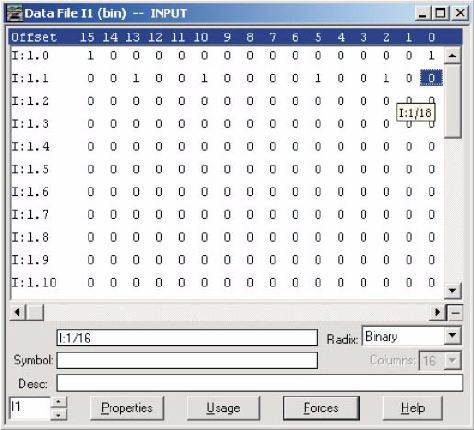
CHAPTER A: LM10 AND ALLEN-BRADLEY SLC500 VIA DEVICENET™
LM10 MOTOR PROTECTION SYSTEM – INSTRUCTION MANUAL A–21
ZIn RSLogix 500, open the O0-Output and I1-Input force files.
FIGURE A–8: Input Force File
ZTo turn on the Run1 contactor, toggle the O:1/16 bit to 1. To turn off
Run1, set this bit to 0.
The status of the Run1 contactor is indicated by the I:1.1/18 bit.
The remote (DeviceNet) control is indicated by the I:1.1/21 bit.
The COS I/O messaging data is available in the I1-Input file, bits I:1.1/24 and onwards.
A.3.8 Explicit Messaging with the LM10 Relay
Explicit messages are stored in the data table of the SLC processor in hexadecimal format.
An M0 copy instruction is used to send the message to the 1747-SDN-scanner module. The
scanner module takes the data and formats it into the proper protocol for transmission on
the DeviceNet network. The destination device (node) receives the message, takes the
appropriate action depending upon the type of command, and formats a reply message
for transmission on the network. The scanner module receives the message that contains
information on the success or failure of the command. The SLC processor uses an M1 copy
instruction to get the message response information from the scanner module. The status
information is placed in the SLC processor data table.
The discussion of Explicit Messaging will be limited to only the elements necessary to allow
this application to function and those that are necessary to provide basic understanding of
the application logic.
Explicit Messaging uses Class, Instance, and Attribute data to build its message structure.
Upon completion of a successful transaction, the logic automatically increments the TXID#
and is ready for the next transaction. Also, the Status data received will be reflected in
Status Word I:s.0 Bit-15. A “1” will be shown for successful message completion. Refer to
the table below for all Status codes as provided by ODVA specification.

A–22 LM10 MOTOR PROTECTION SYSTEM – INSTRUCTION MANUAL
LM10 AND ALLEN-BRADLEY SLC500 VIA DEVICENET™ CHAPTER A:
A.3.9 Data Table Layout
The data table layout is shown below.
Note that X will be any number set in the data file.
The TXID high byte is used for message tracking and is incremented and checked by ladder
logic. The Command low byte is defined as follows:
• 1 = Execute the block
• 2 = Clear response buffer (1747-SDN only)
• The Port high byte is defined as follows:
• 0 = Channel A
• 1 = Channel B
The Port byte is always “0” for the 1747-SDN.
The Size low byte represents the number of bytes in the transaction body. Essentially, this
is the number of bytes following the MAC ID field.
The Service high byte is defined as follows:
Table A–3: Status Codes Provided by ODVA Specification
Status Data Definition
0 Transaction Block Empty
1 Transaction successful
2 Transaction in progress
3 Slave not in scan list
4 Slave offline
5 DeviceNet port disabled
6 Transaction TXID unknown
7 Unused
8 Invalid command
9 Scanner out of buffers
10 Other transaction in progress
11 Could not connect to slave device
12 Response data too large for block
13 Invalid port
14 Invalid size specified
15 Connection bust
Table A–4: Data Table Layout
Data Location High Byte Low Byte
N X:0 TXID Command
N X:1 Port Size
N X:2 Service MAC ID
N X:3 Class (high byte) Class (low byte)
N X:4 Instance (high byte) Instance (low byte)
N X:5 Attribute (high byte) Attribute (low byte)
N X:6 Data (high byte) Data (low byte)

CHAPTER A: LM10 AND ALLEN-BRADLEY SLC500 VIA DEVICENET™
LM10 MOTOR PROTECTION SYSTEM – INSTRUCTION MANUAL A–23
• 0E (hex), 14 (decimal) = Get Attribute Single (read a single parameter)
• 10 (hex), 16 (decimal) = Set Attribute Single (write a single parameter)
• 32 (hex), 50 (decimal) = Get Attribute Multiple (read multiple parameters)
The MAC ID low byte is destination code 09.
The transaction body consists of the Class, Instance, Attribute, and Data bytes.
A.3.10 Ladder Logic
This discussion refers to the Ladder Logic diagrams shown on the following pages.
1. Rung 0000 to Rung 0004 are used to toggle the Bit B4/0 every 1 second; this is the
input to BSL (Bit Shift Left).
2. For every 1 second toggle of B4/0, left-shift the N9:0 register.
3. The bits in the N9:0 register are used to enable Rungs 0007 to 0012.
4. Rung 0006 is used to reload the N9:0 register after overflow.
5. The COP function is used to copy the contains of the M1 file to a specific N register and
transfer the values to the M0 file.
Table A–5: Data to Get Trip Class
Address Data (hex) Description
N31:0 0101 TXID / Command
N31:1 0008 Port / Size
N31:2 0E09 Service / MAC ID (Node 09)
N31:3 0064 Class
N31:4 0001 Instance
N31:5 002F Attribute (Trip Class)
Table A–6: Data for Explicit Message Response, M1 Transferred to N20
Address Data (hex) Description
N32:0 0101 TXID / Command
N32:1 0002 Port / Size
N32:2 8E09 Service / MAC ID (Node = 09)
N32:3 Trip Class Value Service Response Data

A–24 LM10 MOTOR PROTECTION SYSTEM – INSTRUCTION MANUAL
LM10 AND ALLEN-BRADLEY SLC500 VIA DEVICENET™ CHAPTER A:
Refer to the DeviceNet Object Model of the LM10 relay for detail information on Class,
Instance, and Attribute.
Table A–7: Data to Get Motor Run Time
Address Data (hex) Description
N19:0 0101 TXID / Command
N19:1 0008 Port / Size
N19:2 0E09 Service / MAC ID (destination = 63)
N19:3 0064 Class
N19:4 0001 Instance
N19:5 0015 Attribute (Motor Run Time)
Table A–8: Data for Explicit Message Response, M1 Transferred to N20
Address Data (hex) Description
N20:0 0101 TXID / Command
N20:1 0002 Port / Size
N20:2 8E09 Service / MAC ID (Node = 09)
N20:3 Motor Run Time Value Service Response Data
CHAPTER A: LM10 AND ALLEN-BRADLEY SLC500 VIA DEVICENET™
LM10 MOTOR PROTECTION SYSTEM – INSTRUCTION MANUAL A–25
FIGURE A–9: Ladder Logic, Rungs 0000 to 0005
A–26 LM10 MOTOR PROTECTION SYSTEM – INSTRUCTION MANUAL
LM10 AND ALLEN-BRADLEY SLC500 VIA DEVICENET™ CHAPTER A:
FIGURE A–10: Ladder Logic, Rungs 0006 to 0008
CHAPTER A: LM10 AND ALLEN-BRADLEY SLC500 VIA DEVICENET™
LM10 MOTOR PROTECTION SYSTEM – INSTRUCTION MANUAL A–27
FIGURE A–11: Ladder Logic, Rungs 0009 to 0013
A–28 LM10 MOTOR PROTECTION SYSTEM – INSTRUCTION MANUAL
LM10 AND ALLEN-BRADLEY SLC500 VIA DEVICENET™ CHAPTER A:

INDEX
LM10 MOTOR PROTECTION SYSTEM – INSTRUCTION MANUAL I–1
Index
Inde x
A
APPLICATION .....................................................................................................5-61
AUTORESTART ..................................................................................................4-35
AUXILIARY RELAY..............................................................................................4-37
AUXILIARY SENSE FAILURE...............................................................................4-34
B
BAUD RATE ......................................................................................................... 1-5
BLOCK DIAGRAM ................................................................................................ 1-3
C
CAN ..................................................................................................................... A-2
CERTIFICATION .................................................................................................1-11
COMMUNICATIONS
DeviceNet .........................................................................................................5-45
RS232 .....................................................................................................2-13, 5-63
serial port..........................................................................................................5-63
specifications ....................................................................................................1-10
CONFIGURATION ...............................................................................................3-21
CONTROL POWER TRANSFORMER ...................................................................4-31
CONTROL RELAYS .............................................................................................. 1-2
CONTROL TERMINALS .......................................................................................2-14
CONTROL TRANSFORMER.................................................................................4-31
CONTROLLER AREA NETWORK .......................................................................... A-2
COOL DOWN TIMES ...........................................................................................4-27
CPT ....................................................................................................................4-31
CT TURNS ..........................................................................................................4-31
CUB INDICATOR .................................................................................................. 1-4
CURRENT INPUTS ............................................................................................... 1-2
CURRENT UNBALANCE ...............................................................................1-4, 4-33
D
DEVICENET
fault ..................................................................................................................4-36
features ............................................................................................................. A-3
messaging ......................................................................................................... A-3
operations ................................................................................................. 5-45, A-2
overview ............................................................................................................ A-1
specifications ....................................................................................................1-10
DIMENSIONS ......................................................................................................2-17
DOOR MOUNT ....................................................................................................2-18
E
ELAPSED TIME METER ......................................................................................4-40
F
FEATURES ................................................................................................... 1-2, 1-5
FULL LOAD CURRENT ........................................................................................4-33

I–2 LM10 MOTOR PROTECTION SYSTEM – INSTRUCTION MANUAL
INDEX
G
GF INDICATOR .....................................................................................................1-4
GROUND FAULT ..........................................................................................1-4, 4-33
GROUND FAULT RELAY .......................................................................................1-2
H
HISTORY VALUES ..............................................................................................4-41
HUMIDITY ........................................................................................................... 1-11
I
INDICATORS ........................................................................................................1-4
INTERFACE ........................................................................................................3-19
INTRODUCTION....................................................................................................1-1
J
JAM ....................................................................................................................4-33
K
KEYPAD .............................................................................................................3-19
L
LANGUAGE.........................................................................................................4-31
LCD ........................................................................................................... 3-19, 3-21
LED INDICATORS .................................................................................................1-4
LOAD LOSS ........................................................................................................4-34
M
MAC ID SWITCH ...................................................................................................1-4
MAINTAINED SWITCHING...................................................................................4-35
MECHANICAL JAM..............................................................................................4-33
MECHANICAL STALL ..........................................................................................4-33
METERING ...........................................................................................................1-7
MODULE STATUS .................................................................................................1-4
MOTOR TYPE .....................................................................................................4-32
MOUNTING ................................................................................................ 2-17, 2-18
MS INDICATOR.....................................................................................................1-4
N
NETWORK STATUS ..............................................................................................1-4
NS INDICATOR .....................................................................................................1-4
O
OC INDICATOR.....................................................................................................1-4
ORDER CODES ....................................................................................................1-6
OVERCURRENT ..........................................................................................1-4, 4-25
OVERVIEW ...........................................................................................................1-2

INDEX
LM10 MOTOR PROTECTION SYSTEM – INSTRUCTION MANUAL I–3
OVERVOLTAGE ..................................................................................................4-35
P
PASSCODE.........................................................................................................4-37
PDU ..................................................................................................................... 1-4
POLL GROUP......................................................................................................4-36
POWER SUPPLY.................................................................................................. 1-3
PROGRAMMABLE RELAY .................................................................................... 1-2
PROGRAMMING ........................................................................................4-29, 4-30
PROGRAMMING AND DISPLAY UNIT ................................................................... 1-4
R
RELEASE DATES ................................................................................................6-65
REVISION HISTORY ...........................................................................................6-65
RS232 PORT.......................................................................................................2-13
RUN OPERATIONS .............................................................................................4-38
RUNNING HOURS ...............................................................................................4-36
S
SENSOR PACK INPUT ........................................................................................2-15
SPECIFICATIONS ................................................................................................ 1-7
STALL .................................................................................................................4-33
STARTER TYPE ..................................................................................................4-32
STATUS VALUES ................................................................................................4-39
SWITCHES........................................................................................................... 1-4
SYSTEM FREQUENCY ........................................................................................4-36
T
TEMPERATURE ..................................................................................................1-11
TIME DELAYS .....................................................................................................4-34
TRIP CLASS......................................................................................................... 1-5
TRIP CURVES............................................................................................4-25, 4-27
TYPICAL WIRING DIAGRAM................................................................................2-15
U
UNDERVOLTAGE ................................................................................................4-35
V
VOLTAGE INPUTS ............................................................................................... 1-2
W
WARRANTY ........................................................................................................6-67
WIRING
description ........................................................................................................2-13
RS232 ..............................................................................................................2-13
typical wiring diagram ........................................................................................2-15
I–4 LM10 MOTOR PROTECTION SYSTEM – INSTRUCTION MANUAL
INDEX
