Ge Appliances Turboexpander Compressors Brochure
Ge-Turboexpander-Compressors-Brochure-648660 ge-turboexpander-compressors-brochure-648660
2015-08-07
: Ge-Appliances Ge-Turboexpander-Compressors-Brochure-648660 ge-turboexpander-compressors-brochure-648660 ge-appliances pdf
Open the PDF directly: View PDF ![]() .
.
Page Count: 5
GE Oil & Gas
Turboexpander-compressors
Increased efficiency for refrigeration applications

Turboexpander-
compressors
Turboexpanders are used in all segments
of the oil and gas industry to produce
cryogenic refrigeration, while increasing
the facility’s energy efficiency and reducing
its CO2 footprint. Alternative approaches
include expansion of the gas stream
through a valve, which does not recover
energy, and external refrigeration, which
consumes energy. A turboexpander, on the
other hand, is a pressure let-down device
that produces cryogenic temperatures
while simultaneously recovering energy
from a plant stream in the form of shaft
power that can be used to drive other
machinery such as a compressor. This
approach avoids fuel consumption,
improves overall process efficiency and
reduces the plant’s environmental impact.
How they work
A turboexpander expands process fluid
from the inlet pressure to the discharge
pressure in two steps: first through
variable inlet guide vanes and then
through the radial wheel. As the
accelerated process fluid moves
from the inlet guide vanes to the
expander wheel, kinetic energy is
converted into useful mechanical
energy – extracting energy from the
process fluid and cooling it down.
The mechanical energy is available
to drive other process equipment
– in this case, a compressor.
Design & performance to rely on
GE Oil & Gas turboexpander-compressors are available
in a wide selection of frame sizes to match virtually any
application. Our high-efficiency designs are created with
the most advanced computational tools to ensure optimal
refrigeration and energy recovery. Over 60 years of
turbomachinery experience and an operational database
from the industry’s largest installed fleet guarantee a robust
design and a long mean time between maintenance.
Best match to the application
Large portfolio of frame sizes including large-capacity •
machines
Optimized footprint and weight for offshore applications•
High performance
State-of-the-art design and validation tools; large database •
of verified wheels
Proven innovations from GE Engineering Centers of •
Excellence
Optimal integration with other GE Oil & Gas equipment•
High availability
Robust, proven designs based on extensive installed base•
Worldwide, regional support through the GE Oil & Gas •
Global Services network
Coordinated project management
Single point of contact for plant equipment and controls, •
installation, startup, commissioning and service
Capability of full-load string testing with up- or •
downstream compressor
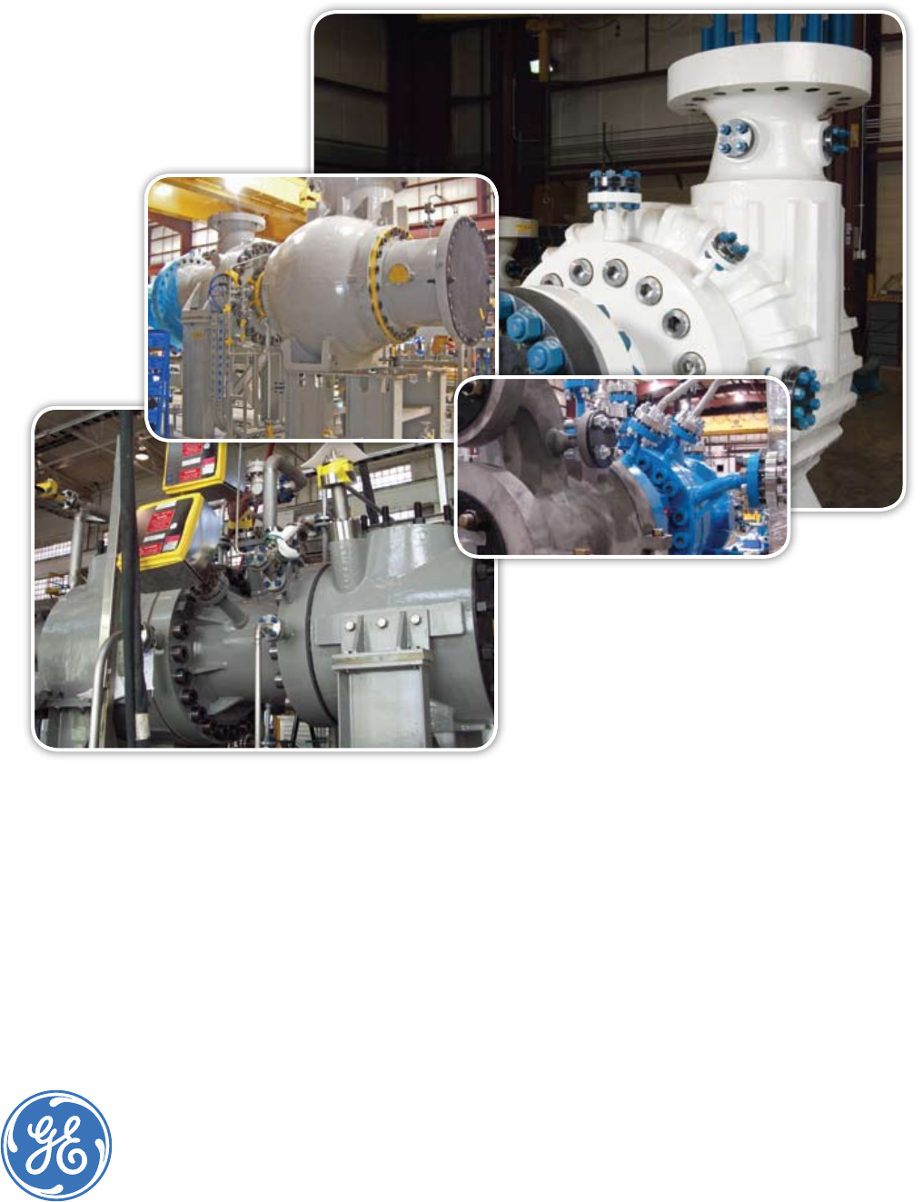
Turboexpander-compressor
with oil bearings. A variety
of models are also
available with active
magnetic bearings.
Typical applications
Floating LNG: turboexpander-compressors offer lighter weight, •
more compact and more efficient refrigeration cycles for the
liquefaction of natural gas
Liquefied petroleum gas (LPG)/natural gas liquids (NGL): •
turboexpander-compressors provide energy-efficient cryogenic
refrigeration for more complete removal of condensates (LPG or
NGL) from hydrocarbon gas streams
Ethylene: turboexpander-compressors increase the overall •
plant efficiency by tail gas refrigeration and subsequent fuel gas
recompression
Dew point control: turboexpander-compressors chill gas streams •
for the removal of moisture to provide dry gas or to control the
heating value of fuel gases
GE Oil & Gas key references
Qatar Shell Pearl: first GTL turboexpander-compressor •
(Frame 60, 13,900 HP)
Ras Laffan: highest power active magnetic bearing •
turboexpander-compressor (Frame 60, 15,100 HP)
Qatar Petroleum (offshore): first NACE-compliant active •
magnetic bearing (Frame 50, 5,100 HP)
N’kossa LPG: first active magnetic bearing installed on •
an FPSO (Frame 40, 4,900 HP)
Tasnee Petrochemicals: two-stage tail gas machine •
for 1.0 Mtpa ethylene plant (Frame 40, 1,500 HP)
BP Cusiana: high-pressure dew point control turboexpander-•
compressors (Frame 20S, 1,400 HP)
Technologies
for extreme challenges
With over 900 turboexpander-compressors in operation worldwide,
GE Oil & Gas has the largest installed base in the industry.
GE Oil & Gas
GE imagination at work
Turboexpander-compressors
Robust, smaller footprint & enhanced performance
for the most demanding applications
Smaller packages and bigger results
for plants on land and at sea
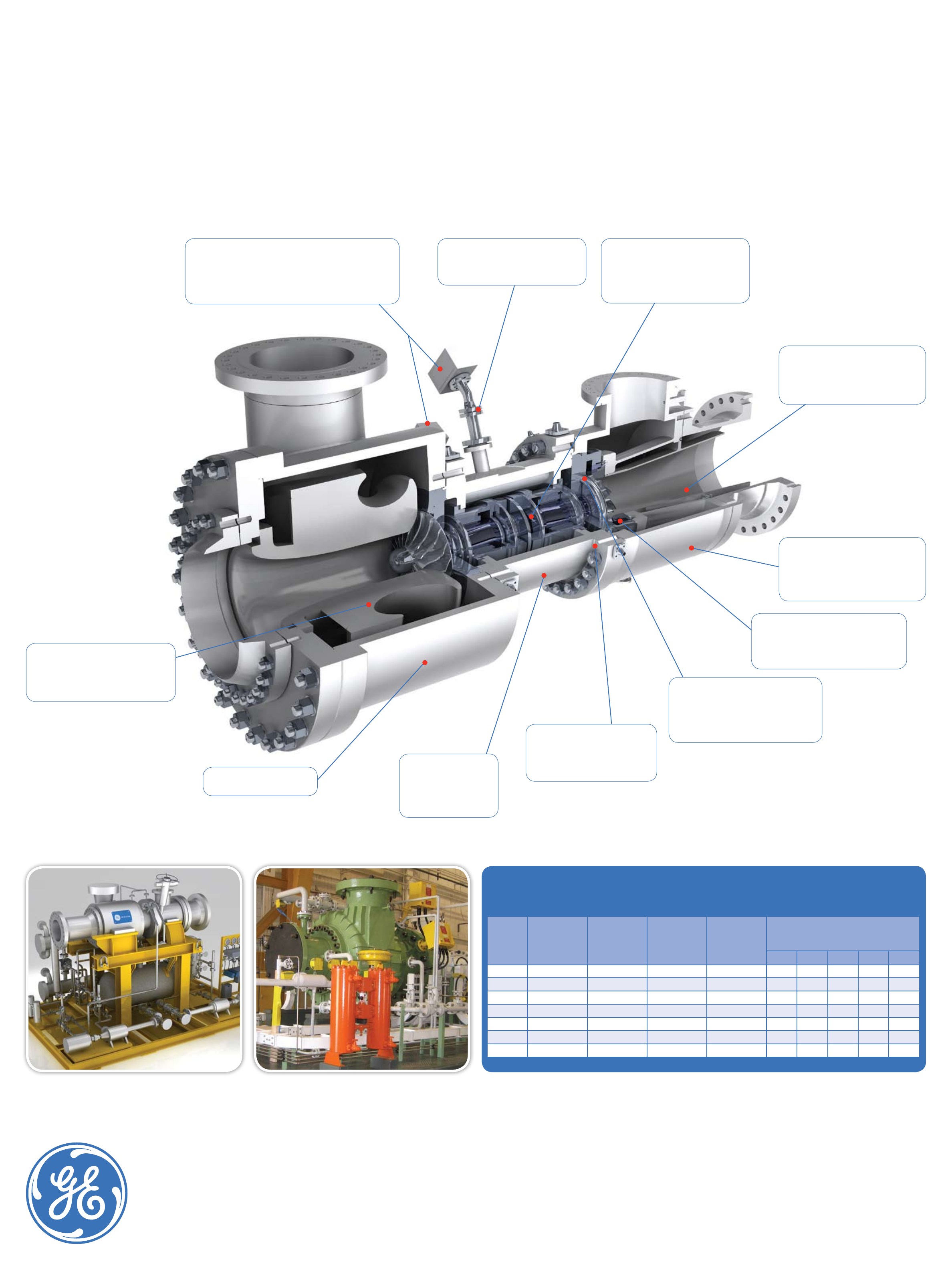
Frame
Shaft power
(kW)
Expander
outlet flow
max.
(m3/h)
Expander
inlet/outlet
flange max.
(in)
Compressor
inlet/outlet
flange max.
(in)
Available casing ratings
150 300 600 900 1500
20 1,600 4,000 8 / 10 14 / 14 ••••
25 2,000 5,500 10 / 12 18 / 16 ••••
30 4,800 9,000 12 / 18 20 / 18 •••••
40 6,500 16,000 16 / 24 26 / 24 ••••
50 10,000 25,000 20 / 30 32 / 28 ••••
60 15,000 36,000 24 / 36 40 / 36 ••••
80 20,000 45,000 26 / 40 42 / 38 •••
FR50 with oil bearings FR50 with active magnetic bearings
ge.com/oilandgas
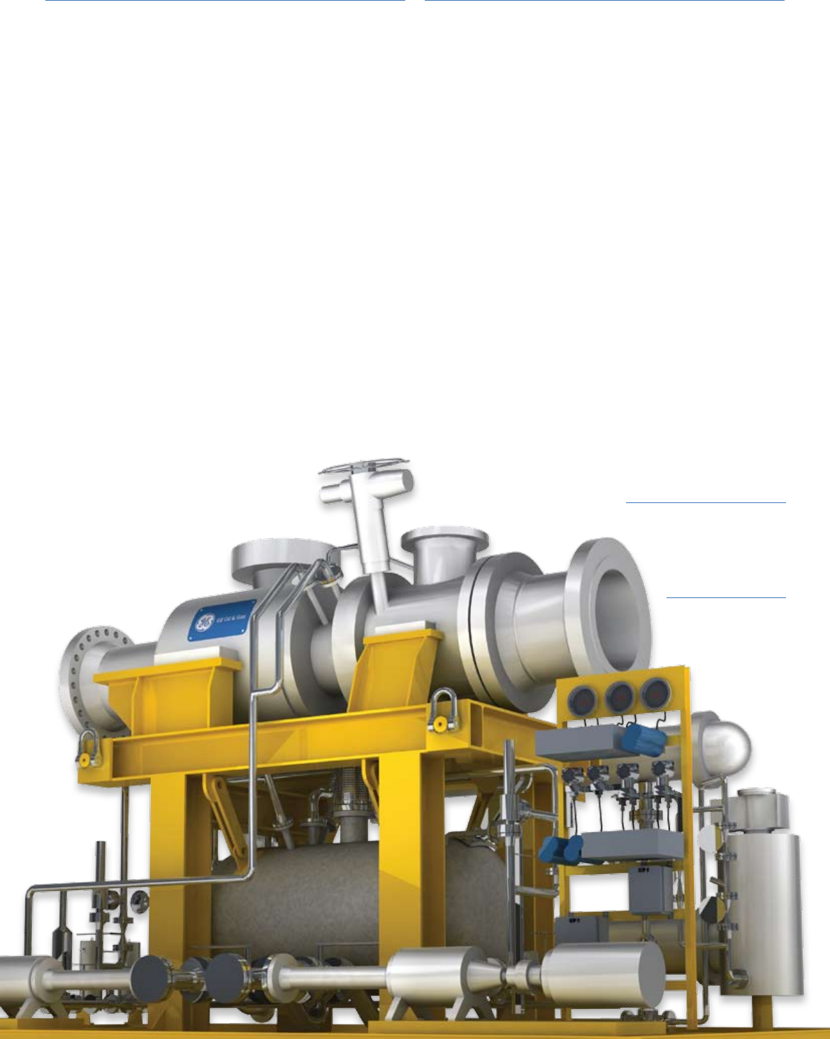
Turboexpander-
compressor with
active magnetic
bearings. A variety
of models are also
available with oil
bearings.
AMB junction boxes (signal & power)
Part of our standard active magnetic bearing (AMB) design. Two
boxes for signal cable connection to monitor the bearing position,
speed and temperature. Two boxes for power cable connection. All
AMB junction boxes and feed-through seals are pressure tested to
the highest standard.
Feed-through seal connection
Provides a hermetic seal between the power
and signal junction box and pressurized
bearing housing.
Active magnetic bearings
In standard or “canned” configuration,
these are fully NACE compliant for sour-gas
service. Steel forged bearing housing provides
maximum stiffness to withstand high process
piping loads.
Expander diffuser
Finalizes expansion of process gas, further
decelerating the flow to increase pressure
drop through the expander. Typically carbon
or stainless steel.
Expander casing
Fabricated from plates and forgings 100%
NDE inspected, geometry optimized with CFD
to minimize flow distortions. Special “zero
leakage” solutions available for sour and toxic
gases. Available in carbon or stainless steel.
Nozzle assembly (inlet guide vanes)
Aerodynamically customized to maintain
superior flow characteristics over a wide range
of process conditions; mechanically designed to
withstand liquid droplets and solid particles.
Expander wheel
Open or closed design. CFD designed for
highest efficiency and milled from single-piece
aluminum, titanium alloy or stainless steel.
Lightweight for stable rotor dynamics. Can
handle condensing streams.
Heat barrier wall (expander seal)
Separates the cryogenic environment
from the warm bearing housing.
Typically Micarta with special insert to
accomodate the seal gas labyrinth.
Bearing housing
Available in oil or magnetic
bearing design, typically in
carbon or stainless steel
and designed for the highest
stiffness and strength.
Compressor casing
Typically carbon or stainless steel.
Compressor discharge scroll
Increases pressure rise at discharge of
impeller to enable higher compression ratios.
All scrolls are of cast type and designed for
easy disassembly.

GE Oil & Gas
Global Headquarters
Via Felice Matteucci, 2
50127 Florence, Italy
T +39 055 423 211
F +39 055 423 2800
customer.service.center@ge.com
Nuovo Pignone S.p.A.
Americas Regional Headquarters
4424 West Sam Houston Parkway North
Houston, Texas 77041
P.O. Box 2291
Houston, Texas 77252-2291
T +1 713 683 2400
F +1 713 683 2421
For complete contact information,
please refer to our website.
ge.com/oilandgas
The information contained herein is general in nature
and is not intended for specific construction, installation
or application purposes. GE reserves the right to make
changes in specifications or add improvements at any
time without notice or obligation.
©2010 General Electric Company
All Rights Reserved
GE_TXComp_Brochure_020310
GE imagination at work
